Embed Size (px)
Citation preview
European Aviation Safety Agency — Rulemaking Directorate
Comment-Response Document 2013-02
Applicability Process map
Affected
regulations and decisions:
CS-25 (Decision 2003/2/RM) Concept Paper:
Terms of Reference:
Rulemaking group:
RIA type:
Technical consultation during NPA drafting:
Publication date of the NPA:
Duration of NPA consultation:
Review group:
Focussed consultation:
Publication date of the Opinion:
Publication date of the Decision:
No
9.2.2009
Yes
Light
No
22.1.2013
3 months
Yes
No
N/A
2013/Q4
Affected
stakeholders:
Large aeroplane manufacturers;
design organisations developing changes or STC for large aeroplanes
Driver/origin: Safety
Reference: N/A
TE.RPRO.00064-001 © European Aviation Safety Agency. All rights reserved.
Proprietary document. Copies are not controlled. Confirm revision status through the EASA Internet/Intranet. Page 1 of 92
Protection from debris impacts
CRD TO NPA 2013-02 — RMT.0048 (25.028) — 19.12.2013
EXECUTIVE SUMMARY
This Comment-Response Document (CRD) contains the comments received on NPA 2013-02 (published on 22 January 2013) and the responses of the Agency to each individual comment. In addition, a summary of
comments and responses is provided.
The responses to the comments on NPA 2013-02 were prepared by the Agency taking into account the recommendations from a Review Group which comprised representatives of the industry (Airbus, Boeing, Rolls-Royce) and national aviation authorities (EASA, ENAC Italy, FAA, TCCA).
New CS-25 certification standards are introduced for protection of large aeroplanes against some categories of threats: tyre and wheel failure (debris, burst pressure effect), small engine debris, and
runway debris. This includes a new CS 25.734 specification and its related Acceptable Means of Compliance (AMC) 25.734 providing a tyre and wheel failure model that is applicable to the protection of structures and systems. The applicability of the existing CS 25.963(e) specification is expanded from fuel tank access covers to aircraft fuel tanks and the applicable threats now include wheel fragments and APU small fragments; the related AMC 25.963(e) has been updated accordingly, and its small engine debris model has been confirmed for fuel tanks along with pass-fail criteria.
Based on the comments received and the responses provided thereto, the proposed CS-25 amendment
text was updated and is provided in this CRD. Some adjustments were made to the models provided in
AMC 25.734 for protection against tyre and wheel failure and in AMC 25.963(e) for fuel tank protection. Various clarifications and corrections were also made (Certification Specifications and Acceptable Means of Compliance). Nevertheless, the objectives and the substance of the proposed amendment are unchanged.
European Aviation Safety Agency CRD to NPA 2013-02
Table of contents
TE.RPRO.00064-001 © European Aviation Safety Agency. All rights reserved.
Proprietary document. Copies are not controlled. Confirm revision status through the EASA Internet/Intranet. Page 2 of 92
Table of contents
1. Procedural information ........................................................................................... 3
1.1. The rule development procedure...................................................................... 3
1.2. The structure of this CRD and related documents ............................................... 3
1.3. The next steps in the procedure ...................................................................... 3
2. Summary of comments and responses ..................................................................... 4
3. CS-25 Amendment 14 — Resulting text .................................................................... 8
4. Individual comments and responses ......................................................................... 9
5. Updated NPA 2013-02 Explanatory Note ................................................................. 54

European Aviation Safety Agency CRD to NPA 2013-02
1. Procedural information
TE.RPRO.00064-001 © European Aviation Safety Agency. All rights reserved.
Proprietary document. Copies are not controlled. Confirm revision status through the EASA Internet/Intranet. Page 3 of 92
1. Procedural information
1.1. The rule development procedure
The European Aviation Safety Agency (hereinafter referred to as the ‘Agency’) developed
this Comment-Response Document (CRD) in line with Regulation (EC) No 216/20081
(hereinafter referred to as the ‘Basic Regulation’) and the Rulemaking Procedure2.
This rulemaking activity is included in the Agency’s Rulemaking Programme for
2013–2016 under RMT.0048 (25.028). The scope and timescale of the task were defined in
the related Terms of Reference (see process map on the title page).
The draft CS-25 amendment has been developed by the Agency based on the input of the
Rulemaking Group RMT.0048 (25.028). All interested parties were consulted through NPA
2013-023, which was published on 22 January 2013. 83 comments were received from
interested parties, including industry and national aviation authorities.
The text of this CRD has been developed by the Agency based on the input of the Review
Group RMT.0048 (25.028).
1.2. The structure of this CRD and related documents
This CRD provides a summary of comments and responses as well as the full set of
individual comments and responses thereto received to NPA 2013-02. The resulting rule
text is provided in Chapter 3 of this CRD.
1.3. The next steps in the procedure
The Decision containing the CS-25 amendment will be published by the Agency during
2013/Q4.
1 Regulation (EC) No 216/2008 of the European Parliament and the Council of 20 February 2008 on common rules in the
field of civil aviation and establishing a European Aviation Safety Agency, and repealing Council Directive 91/670/EEC, Regulation (EC) No 1592/2002 and Directive 2004/36/EC (OJ L 79, 19.3.2008, p. 1), as last amended by Commission Regulation (EU) No 6/2013 of 8 January 2013 (OJ L 4, 9.1.2013, p. 34).
2 The Agency is bound to follow a structured rulemaking process as required by Article 52(1) of the Basic Regulation. Such process has been adopted by the Agency’s Management Board and is referred to as the ‘Rulemaking Procedure’. See Management Board Decision concerning the procedure to be applied by the Agency for the issuing of Opinions, Certification Specifications and Guidance Material (Rulemaking Procedure), EASA MB Decision No 01-2012 of 13 March 2012.
3 http://www.easa.eu.int/rulemaking/notices-of-proposed-amendment-NPA.php
European Aviation Safety Agency CRD to NPA 2013-02
2. Summary of comments and responses
TE.RPRO.00064-001 © European Aviation Safety Agency. All rights reserved.
Proprietary document. Copies are not controlled. Confirm revision status through the EASA Internet/Intranet. Page 4 of 92
2. Summary of comments and responses
The Agency received 83 comments from 16 stakeholders (National Aviation Authorities
(NAAs), aeroplane manufacturers and other private companies). Overall the objectives of
the NPA were supported by NAAs and the industry. However, some items of the proposed
AMC materials were challenged or not fully understood. The comments received provided
the opportunity to make some improvements and adjustments to the proposal, as well as
to clarify some explanations and background.
Each comment has been individually replied (refer to Chapter 4 below).
In addition, some of the most substantial comments and the Agency responses are
summarised below.
The explanatory note of the NPA has also been revised consistently and is provided in
Chapter 5 below.
The resulting text of the proposed CS-25 amendment is available in Chapter 3.
a) Comments related to small engine debris threat
Regarding the CS 25.963(e) rule, only a wording improvement has been made as
suggested by a commentator.
The comments received were essentially on the proposed threat model (9.5 mm
(3/8in) cube at 213.4 m/s (700 ft/s)) in AMC 25.963(e).
Some comments revealed that the proposed threat model was not fully accepted
because the commentators considered that this threat model interferes with the AMC
20-128A model and, therefore, would add unnecessary additional complications. It
has been suggested to only refer to AMC 20-128A. This opinion is not shared by the
Agency because the proposed model addresses a wider range of threat than the
current
AMC 20-128A small fragment model which is limited to small rotating debris, and
therefore it is maintained. The new proposed model addresses rotating and non-
rotating debris, including ricochets, which represent a threat for the fuel tanks as
supported by data from accidents and incidents. It is also reminded that the 9.5 mm
(3/8 in) cube is already present in the current AMC 25.963(e) and was successfully
applied to fuel tank access covers. Its applicability is now expanded to fuel tanks and
is not anymore limited to the access covers. When a revision of AMC/AC 20-128A is
decided in the future, it is agreed that it should be considered to integrate the threat
defined in the AMC 25.963(e) as far as possible.
The proposed model threat area included the ± 15-degree area for which a normal
impact is considered, and all other angles for which a credit for oblique angles is
possible. Some commentators opposed the expansion beyond the ± 15-degree area,
arguing that it would increase certification cost and that it would potentially lead to
increased thickness and weight. It is reminded that the credit for impact angle in this
area limits the impact of the threat, and as recognised during the Rulemaking Group
meetings this should not carry any significant weight penalty, if there should be any
considered necessary. However, it is decided to limit the threat area expansion to the
zone where most of the fragments and also the most significant damages are found.
As shown on p. 10 of the NPA, this area corresponds to angles between

European Aviation Safety Agency CRD to NPA 2013-02
2. Summary of comments and responses
TE.RPRO.00064-001 © European Aviation Safety Agency. All rights reserved.
Proprietary document. Copies are not controlled. Confirm revision status through the EASA Internet/Intranet. Page 5 of 92
– 45 degrees (aft) and + 15 degrees (forward). The model has been updated
(oblique impact can be considered in the – 15/– 45-degree area).
Some commentators reported that it was not clear if AMC 20-128A remains
applicable to other systems and structures. It is confirmed, as stated in a note part
of AMC 25.963(e), that AMC 20-128A remains applicable to engine debris, other than
small engine fragments, threatening fuel tanks, and also remains applicable to all
engine debris to other areas of the aircraft structures and systems.
b) Comments related to the tyre and wheel failure threat
The CS 25.734 rule has been reworded for clarification but the objective is
unchanged. The CS 25.963(e) rule amendment proposal is unchanged for the
aspects concerning tyre and wheel debris. Comments were essentially focussed on
the AMC 25.734 models.
One commentator proposed that only (small) tyre debris should be considered for
residual strength and damage tolerance analysis, arguing that in a recent CRI this
was requested for tyre debris only. The Agency reviewed the text of the CRI referred
to by the commentator. This CRI provides interpretative material on Fatigue and
Damage Tolerance (F&DT) of CFRP Structure. The following paragraphs of the CRI
indicate that it does not limit itself to small tyre debris:
— ‘CS 25.571 implies that all PSE structure should be addressed in relation to all
damage threats (production and service). As the A350 design could potentially
set a precedent, this CRI requires that all such threats be explicitly identified by
the applicant and the potential for damage be shown to be fully applied to
F&DT test and analysis.
— The applicant is required to clearly identify any, and all, possible threats and
associated damages so that F&DT requirements can be satisfied and
substantiated appropriately. Threats include, but are not limited to: production
defects, tyre debris, rotor debris, overload (ground impact, jacking, gust, and
maneuvers outside the design envelope), lightning, fire (in-flight and post
crash) including heat damage, hail (ground and in-flight), runway debris etc.’
It is decided to recognise in AMC 25.734 that the previously certified traditional
aeroplanes (i.e. configurations featuring high aspect ratio wings built around a single
torsion box manufactured of light metal alloy) have demonstrated inherent structural
robustness with regard to tyre and wheel debris threats. Residual strength and
damage tolerance evaluations might therefore not be required for aeroplanes
featuring such design features. However, for aeroplanes with novel or unusual design
features, for principal structural elements (PSE) and primary structures, the AMC
25.734 debris models are threats to be considered; this is consistent with the CRI
mentioned above.
Similarly, it is recognised that in-service experience shows a good safety record for
the fuel tanks located within the torsion box of high aspect ratio wings manufactured
of light metal alloy, owing to the intrinsic characteristics of the structure, including
the wing skin gauge and typical arrangement of the stringers and ribs. Therefore, for
tanks located within similar structures, in the absence of any unusual design
feature(s), fuel tank penetration evaluation needs only to consider small tyre debris.
European Aviation Safety Agency CRD to NPA 2013-02
2. Summary of comments and responses
TE.RPRO.00064-001 © European Aviation Safety Agency. All rights reserved.
Proprietary document. Copies are not controlled. Confirm revision status through the EASA Internet/Intranet. Page 6 of 92
The related note in paragraph 3 is deleted and replaced by new subparagraphs 3.2
and 3.3 which reflect the above principles.
Tyre debris threat model:
Some clarifications were made to improve the text and the drawing, but the essential
elements and objectives are unchanged.
Tyre burst pressure effect model:
Several comments were received against the tyre burst pressure based on the
‘maximum unloaded rated tyre pressure’, and several changes were proposed. One
commentator argued that this does not take into consideration the 7 % margin of
CS 25.733(c)(1) or the use of tyres with a higher ply rating (and higher rated tyre
pressure) than required for the aeroplane. The Agency decided to change the
criterion to ‘tyre maximum unloaded operational pressure’; however, the 1.3 factor is
applied to account for temperature rise. A definition of the maximum unloaded
operational pressure is added along with an example on how to calculate the burst
pressure.
Flailing tyre strip threat model
For the ‘landing gear retracting or retracted’ configuration, it has been proposed to
upgrade the Guidance Material associated with the credit that can be taken from in-
flight braking systems. The Agency reviewed the proposed guidance and revised it to
better reflect the conditions to be fulfilled.
Wheel flange debris threat model:
No change was made based on the comments received; however, the Agency
considered it necessary to provide some clarification with regard to vertically
released debris. No vertical wheel debris threat model is provided because it is
considered that adequate protection is provided by the tyre debris model 1. This is
now clearly indicated in the model.
c) Comments on hazardous fuel leak criteria
Some commentators asked for more details about the origin of the proposed criteria.
As mentioned in the NPA, this proposal was used in several Certification Review
Items (CRIs) and Issue Papers (IPs) to define a hazardous fuel leak for the
evaluation of tyre debris impacts on fuel tank. The intent is to prevent a leak that will
run or drip from the fuel tank surface. The criteria of the IPs/CRIs were defined
based on the Boeing Airplane Maintenance Manual (section 28-11-00) definitions of
fuel leaks which are divided into four groups as follows:
‘(1) Fuel leakage is divided into four groups to calculate flight safety.
NOTE: The dimension patterns of fuel leaks are based on an examination 15 minutes
after the leak area was rubbed clean.
(a) A stain is a leak where the wetted area is not more than 1 ½ inches wide after
the time interval noted above.
(b) A seep is a leak where the wetted area is not more than 4 inches wide after the
time interval noted above.

European Aviation Safety Agency CRD to NPA 2013-02
2. Summary of comments and responses
TE.RPRO.00064-001 © European Aviation Safety Agency. All rights reserved.
Proprietary document. Copies are not controlled. Confirm revision status through the EASA Internet/Intranet. Page 7 of 92
(c) A heavy seep is a leak where the wetted area is not larger than 6 inches wide
after the time interval noted above.
(d) A running leak is all fuel leaks that are larger than 6 inches wide after the time
interval noted above.
NOTE: Fuel will usually come into view again immediately after being wiped dry and
can run or drip from the surface.’
The ‘heavy seep’ group was therefore considered as the reference for defining a
hazardous fuel leak.
These criteria have been used by Boeing since the 707 aeroplane models (i.e. since
1959) and are considered to be safe based on in-service experience.

European Aviation Safety Agency CRD to NPA 2013-02
3. CS-25 Amendment 14 — Resulting text
TE.RPRO.00064-001 © European Aviation Safety Agency. All rights reserved.
Proprietary document. Copies are not controlled. Confirm revision status through the EASA Internet/Intranet. Page 8 of 92
3. CS-25 Amendment 14 — Resulting text
Please refer to the document ‘CS-25 Amendment 14 — Change Information’.
European Aviation Safety Agency CRD to NPA 2013-02
4. Individual comments and responses
TE.RPRO.00064-001 © European Aviation Safety Agency. All rights reserved.
Proprietary document. Copies are not controlled. Confirm revision status through the EASA Internet/Intranet. Page 9 of 92
4. Individual comments and responses
In responding to comments, a standard terminology has been applied to attest the Agency’s
position. This terminology is as follows:
(a) Accepted — The Agency agrees with the comment and any proposed amendment is wholly
transferred to the revised text.
(b) Partially accepted — The Agency either agrees partially with the comment, or agrees with
it but the proposed amendment is only partially transferred to the revised text.
(c) Noted — The Agency acknowledges the comment but no change to the existing text is
considered necessary.
(d) Not accepted — The comment or proposed amendment is not shared by the Agency.
Note: Some commentators attached a letter providing a list of comments instead of recording
each comment in the applicable section of the NPA. The Agency extracted all individual comments
from these letters and copied them in the applicable section below to facilitate the global review
and the provision of responses to the comments.
(General Comments) -
comment 12 comment by: UK CAA
Please be advised that there are no comments from the UK CAA on NPA 2013-02,
Protection from debris impacts.
response Noted.
comment 21 comment by: DGAC France
DGAC France has no specific comment on this NPA
response Noted.
comment 59 comment by: Gulfstream Aerospace Corporation
Attachment #1
Attached are the compiled Gulfstream Aerospace Corporation Comments to NPA
2013-02
response Noted.
Your comments have been extracted from your letter and addressed in the
applicable sub-chapter below.
comment 60 comment by: Luftfahrt-Bundesamt
The LBA has no comments on NPA 2013-02.
response Noted.
comment 79 comment by: Swiss International Airlines / Bruno Pfister
SWISS Intl Air Lines takes note of the NPA 2013-02 without further comments.

European Aviation Safety Agency CRD to NPA 2013-02
4. Individual comments and responses
TE.RPRO.00064-001 © European Aviation Safety Agency. All rights reserved.
Proprietary document. Copies are not controlled. Confirm revision status through the EASA Internet/Intranet. Page 10 of 92
response Noted.
comment 82 comment by: Bombardier Aerospace
Bombardier supports the changes proposed in this NPA. It clarifies the
requirements needed for future certification programs.
response Noted.
comment 84 comment by: Poonam Richardet
Attachment #2
Please See comments from Cessna Aircraft Company on the following NPA-2013-
02-"Protection from debris impacts."
response Noted.
Your comments have been extracted from your letter and addressed in the
applicable subchapter below.
Gulfstream - General comments:
1.The initiative to clarify, correct and harmonize the requirements, assumptions, definitions and
methods used to assess the safety of transport aircraft with regard to debris impact damage is
very welcome. The broadening of the requirements previously only applicable to fuel tank covers
is a long recognized common sense change. The specificity on the applicability of each type of
consideration is also a positive aspect of the proposed changes.
Response: Noted.
2. One issue of significant concern is the creation and entrenchment of overlapping requirements
and assessment criteria for uncontained debris from engines or APU. Uncontained engine and APU
debris are assessed by detailed and specific methods and criteria. The entrenchment of the "3/8
inch steel cube" impact model as an alternative or additional criterion for fuel tank protection
from uncontained debris is an unnecessary complication and may lead to unequal treatment on
the subject due to certification authority discretion in applying this model, the existing AC/AMC
20-128A model or both to each application.
Gulfstream highly recommends that the Fuel Tank Protection guidance refrain from defining its
own uncontained engine or APU fragment model and instead reference the existing guidance
material on those subjects. The "in the absence of relevant data concerning small engine debris"
consideration is not a typical scenario for transport aircraft certification, as detailed fragment
models are required for 14CFR/CS 25.901 and 25.903 compliance via the method described in
AC/AMC 20-128A.
Gulfstream highly recommends that the fuel tank protection requirement and guidance simply
state that the fuel tank should resist penetration by small debris as defined in AC/AMC 20-128A,
if that is the intended requirement. Gulfstream notes, however, that such a requirement applied
to aircraft with rear fuselage mounted engines represents no significant improvement in safety
and may represent a significant weight penalty. Therefore, Gulfstream suggests this requirement
be limited to impact areas where leaking fluid could come into contact with an ignition source.
Response: Not accepted.
As noted in the NPA, the intent was to review, amend as appropriate, and harmonise the small
debris threat as defined in the existing AMC materials. In the long term a revision to the AC/AMC
20-128A document may be envisaged, possibly using the phase II of the AIA work.
European Aviation Safety Agency CRD to NPA 2013-02
4. Individual comments and responses
TE.RPRO.00064-001 © European Aviation Safety Agency. All rights reserved.
Proprietary document. Copies are not controlled. Confirm revision status through the EASA Internet/Intranet. Page 11 of 92
Furthermore, as stated in AMC 25.963(e), paragraph 3.b(ii), the proposed model is intended to
address small debris (rotating, non-rotating debris and ricochets), whilst the AC/AMC 20-128A
small fragment model addresses only aerofoil tip (rotating debris). Therefore, following the review
of available data, the working group considers that the proposed model (9.5 mm (3/8 in) cube at
213.4 m/s (700 ft/s)) is an appropriate threat addressing a broader range of debris beyond
considering only a rotating part aerofoil tip, which is consistent with the events data analysis
performed. We also remind that the 9.5 mm (3/8 in) cube model was already present in the
current AMC 25.963(e) and it was successfully applied for fuel tank access covers.
The working group recognises that a threat defined more specifically to match engine
performance and characteristics would be preferable and that the AC/AMC 20-128A potentially
offers such a threat. However, as it is evident in the NPA explanations, the data is limited such
that it is difficult to confirm that the performance defined threat based upon rotating part
definition would also correctly and proportionally bound the associated product non-rotating part
debris. Therefore, until more data and resource is available, the AMC 25.963(e) defined threat
model is considered appropriate.
Furthermore, note that this model is part of an AMC material. Therefore, an applicant may
propose an alternative model.
Regarding the APU, note that the proposed AMC 25.963(e) paragraph 3.(iii) already recommends
using the small fragment model defined in AMC 20-128A.
Regarding the pass-fail criteria provided to demonstrate that no hazardous fuel leak is created, as
explained in the NPA (page 19, item 27), it is based on previous CRIs. See also our response to
comment 51. It should be the same for wing or tail mounted engines configurations.
3. A second issue of significant concern is the expansion of the zone in which uncontained engine
debris are considered to be a threat beyond the currently established ± 15 degree area. While it
is recognized that a larger zone may be more realistic (as indicated by the reference data),
making this change here creates the potential for conflicting or overlapping requirements now
and in the future when AC/AMC 20-128A is revised. It also calls into question the suitability of the
current AC/AMC 20-128A, creating the temptation for certification authorities to apply the
expanded small debris impact zones defined here to the general uncontained engine failure
assessment by Issue Paper.
Response: Noted.
The threat area defined beyond the +/-15 degrees zone is intended to protect against identified
threats from uncontained rotor burst events, which include non-rotating debris, and ricochets
effects, and evidences from events analysis showing small engine debris are sent beyond the +/-
15 degrees zone. The limitation in the scope to small engine debris is clearly indicated in the rule
and AMC material, therefore there should not be a reason from this NPA to propose extension to
other categories of debris.
Finally, it is decided to limit the threat area to the zone where we found most of the fragments
and also the most significant damages. As shown in the NPA on page 10, this area corresponds to
angles between -45 degrees (aft) and +15 degrees (forward). A normal impact is to be
considered in the +/-15 degrees while an oblique impact is to be considered in the -15/-
45degrees area.
Cessna – General comments
- Suggestion to: Provide a broader and more coherent guidance relative to fuel tank threats
and protection from small engine debris within a revision to AMC 20-128A.
- Request for clarification: It is not clear if the small fragment data per AMC 20-128A is to be
used when it is available.
Response: Noted.
The working group recognises that a threat defined more specifically to match engine
performance and characteristics would be preferable and that the AC/AMC 20-128A potentially
European Aviation Safety Agency CRD to NPA 2013-02
4. Individual comments and responses
TE.RPRO.00064-001 © European Aviation Safety Agency. All rights reserved.
Proprietary document. Copies are not controlled. Confirm revision status through the EASA Internet/Intranet. Page 12 of 92
offers such a threat. However, as it is evident in the NPA explanations, the data is limited such
that it is difficult to confirm that the performance defined threat based upon rotating part
definition would also correctly and proportionally bound the associated product non-rotating part
debris. Therefore, until more data and resource is available, the AMC defined threat is considered
appropriate.
A. Explanatory Note — VI. Small engine debris —19. References; 20. Scope p. 6
comment 58 comment by: Embraer - Indústria Brasileira de Aeronáutica - S.A.
Embraer would like to offer the following comment in response to NPA 2013-02,
Protection from debris impacts:
The scope change introduced in new AMC 25.963(e) to consider small engine
debris threat model for evaluation of the fuel tank rather than its access covers
only, sets non harmonized approach to perform safety analyses to show
compliance with both CS requirements, since analysis without a small engine
debris model has to be performed for CS 25.903(d)(1). It is stated in pag. 6, item
VI, sec. 20, 1st §: "It does not change the current use of AMC 20-128A regarding
such threats. Furthermore, it does not specifically address the related
specification CS 25.903(d)"...
response Not accepted.
The specific reference to not addressing CS 25.903 is made in the NPA text and
the intention was to identify that the CS/AMC 25.963(e) is being addressed
explicitly in this NPA text, not CS 25.903(d). This may be considered in a future
review of AC/AMC 20-128A. The proposed AMC 25.963(e) also includes in
subparagraph 3.b(ii):
‘Note: AMC 20-128A remains applicable to engine debris, other than small engine
fragments, threatening fuel tanks as described here, and also remains applicable
to all engine debris to other areas of the aircraft structures and systems.’
comment 71 comment by: Dassault Aviation
Dassault-Aviation comment on § 20:
o Small fragments are defined also in AMC 20-128A §9.d. for all stages except the
Fan and by §9.e. for the Fan. Why not to refer to AMC 20-128A and explain why
additional definitions are necessary?
response Not accepted.
The Review Group recognises that a threat defined more specifically to match
engine performance and characteristics would be preferable, and that AC/AMC 20-
128A potentially offers such a threat. However, as it is evident in the NPA
explanations, data is so limited that it is difficult to confirm that the performance-
defined threat based upon rotating part definition would also correctly and
proportionally bound the associated product non-rotating part debris. Therefore,
until more data and resources are available, the AMC-defined threat is considered
appropriate.
A. Explanatory Note — VI. Small engine debris — Ref. 1: DOT/FAA/AR-99/11
‘Large Engine Uncontained Debris Analysis’ Final Report 1999 (generally
referred to as the ‘China Lake’ data)
p. 9-11
European Aviation Safety Agency CRD to NPA 2013-02
4. Individual comments and responses
TE.RPRO.00064-001 © European Aviation Safety Agency. All rights reserved.
Proprietary document. Copies are not controlled. Confirm revision status through the EASA Internet/Intranet. Page 13 of 92
comment 1 comment by: Robert Jones
No fragment sizes or masses are shown(test comment)
response Noted.
Page 9 indicates that China Lake data is incomplete regarding mass, speed, and
size. This is evident in Figure 1, which requires that data be shown in terms of
hole size, and latter dent depth, because no complete debris information exists.
The NPA further explains that this lack of data drives the reverse dent and
penetration energy approach finally used to justify the defined 9.5 mm (3/8 in)
cube 213.4 m/s (700 ft/s) threat.
Explanatory Note - p. 14
Cessna comment:
Recommend providing citations and references on energy absorption formulas to provide further
guidance to the design.
Response: Noted.
The NPA adequately explains the methodology used in conjunction with the referenced public data
to substantiate the content of the proposal.
A. Explanatory Note — VII. Tyre and wheel debris — 31. Background p. 21-22
comment 17 comment by: AIRBUS
Modify:
“The TGM model was developed by JAA early in 2000. It was based on the A320
model from Airbus, which resulted from a BAE study of worldwide events data.
Then the A320 model was updated to remove the probabilistic approach used at
this time. This led to the TGM, which considers that an event will occur and that
the aircraft must be protected.”
by:
“The TGM model was developed by JAA early in 2000. It was based on the A320
model from Airbus, which resulted from a BAE study of worldwide events data.
Then the A320 model was updated to remove the probabilistic approach used at
this time This led to the TGM, which considers that an event will occur and that
the aircraft must be protected.”
JUSTIFICATION
The statement “the A320 model was updated to remove the probabilistic approach
used at this time” is incorrect because probabilistic consideration is still used.
(e.g.: such as to show compliance with 25.1309 requirements for systems)
response Accepted.
A. Explanatory Note — VII. Tyre and wheel debris — 34. Review of tyre and
wheel failure events data; General p. 23-25
comment 50 comment by: AIRBUS
Modify the note
“Where the size of debris is declared not compliant with the TGM, this indicates
that the debris is larger than that described in the model”
European Aviation Safety Agency CRD to NPA 2013-02
4. Individual comments and responses
TE.RPRO.00064-001 © European Aviation Safety Agency. All rights reserved.
Proprietary document. Copies are not controlled. Confirm revision status through the EASA Internet/Intranet. Page 14 of 92
By:
“Where the size of debris is declared not compliant with the TGM, this indicates
that the debris is of larger dimension than that described in the model, although
this does not necessarily mean energy of the debris is outside TGM model.”
RATIONALE / REASON / JUSTIFICATION for the Comment:
There is no indication of the speed of the debris, so conclusion cannot be made on
the energy.
response Accepted.
A. Explanatory Note — VII. Tyre and wheel debris — 34. Review of tyre and
wheel failure events data; Analysis of some events with key elements p. 25-31
comment 72 comment by: Dassault Aviation
Dassault-Aviation comment page#23
o Tyre debris table: To add the mass of the debris
response Not accepted.
The purpose of the table was to collect data at the start of the Rulemaking Group
activity. The Agency sees no benefit in changing it at this stage.
comment 73 comment by: Dassault Aviation
Dassault-Aviation comment § 34 page 25
o “The single retracted wheel flange failure which occurred in service was not
considered to be relevant.” Please refer to Page 28 where it is explained Why.
response Accepted.
Reference to event 4) has been added.
A. Explanatory Note — VII. Tyre and wheel debris — 35. Wheel and tyre failure
model p. 31-34
comment 22 comment by: Boeing
Page: 32
Paragraph: Section 35.(ii) Tyre debris, sub-bullets [5] through [10]
The proposed text states:
“— [5] The speed of the debris is changed to the minimum tyre speed rating
certified for the aircraft instead of maximum rotation speed VR.
— [6] The Working Group initially considered using the maximum ground speed at
rotation VR like in the TGM. It was recognised that the max VR, although it would
rarely be reached at the time of a tyre failure event, would cover all operational
scenarios.
— [7] There was also a discussion about the tyre internal pressure effect on the
debris release speed, not taken into account in the TGM.
— [8] The use of max VR is already a conservative speed as it is rarely reached in
normal operation; in addition, it was deemed improbable that debris are released
exactly at the burst time (pressure release is very quick), especially when the
aircraft speed is reaching VR. So adding max VR plus a pressure release, in
addition to a thickness of the large debris of full tread plus carcass, was

European Aviation Safety Agency CRD to NPA 2013-02
4. Individual comments and responses
TE.RPRO.00064-001 © European Aviation Safety Agency. All rights reserved.
Proprietary document. Copies are not controlled. Confirm revision status through the EASA Internet/Intranet. Page 15 of 92
considered over conservative.
— [9] Finally it was proposed to use the minimum tyre speed rating certified for
the aircraft (the tyre speed rating is the maximum ground speed at which the tyre
has been tested, which is always above the max VR) but without prescribing tyre
internal pressure effect and relaxing the thickness of large debris.
— [10] In addition to being a speed value easy to determine and to use by the
applicant, this adds a margin to the energy level which mitigates the case when
the debris could be released with a thickness including the carcass instead of a
debris with a thickness of full tread plus outermost ply only.”
REQUESTED CHANGE:
Boeing does not agree that the speed of the debris should be changed from the
maximum rotation speed VR (as stated in TGM/25/08, Issue 2, included as
Appendix 1 to this NPA, and successfully applied by JAA/EASA on many previous
airplane certification programs) to the minimum tire speed rating certified for the
aircraft. Therefore, we request that sub-bullets [5], [9], and [10], shown as
italicized red text above, be deleted.
JUSTIFICATION: Boeing does not agree that, as stated in sub-bullet [10], it is
easier for the applicant to to use the minimum tire speed rating certified for use
on the airplane than to continue to use the maximum rotation speed VR (as
defined in CS-Definitions) certificated for the airplane . The applicant is required
by CS 25.733(a) and (c) to install a tire “with a speed rating approved by the
Administrator that is not exceeded under critical conditions.” To comply with that
regulation, the applicant must have full knowledge of the maximum rotation
speed VR that will be certificated on the airplane.
CS 25.733(a) and (c) require that a tire be installed with a speed rating that is
greater than or equal to the maximum rotation speed VR. As clearly stated in sub-
bullets [6] and [8], use of maximum rotation speed VR:
“… would rarely be reached at the time of a tyre failure event,”
“… would cover all operational scenarios,”
“… is already a conservative speed as it is rarely reached in normal
operation,” and
“… it was deemed improbable that debris are released exactly at the burst
time (pressure release is very quick), especially when the aircraft speed is
reaching VR. So adding max VR plus a pressure release, in addition to a
thickness of the large debris of full tread plus carcass, was considered over
conservative.”
Therefore, if using the maximum rotation speed VR is considered “over
conservative,” it is not reasonable to add additional margin, as stated in sub-
bullet [10], by forcing the applicant to use the minimum tire speed rating certified
for the airplane. It may be coincident that the minimum tire speed rating certified
for the airplane is equal to the maximum rotation speed of the airplane, but this is
not always the case.
Tire debris is an airplane-level threat, so it is not appropriate to use parameters
associated at the component, unless the parameter is related or derived from the
geometry of the tire or wheel, as is the case for failing tread shape, thrown tread
shape, thrown tread zone of vulnerability, and burst plume shape. It is more
appropriate to use an airplane-level speed parameter, in this case maximum
rotation speed VR, when assessing the airplane-level threat from thrown tire tread.
response Not accepted.
This release speed was chosen as a compromise based on arguments considering
the concurrent effects from tyre rotation speed, tyre pressure release and tyre
thickness.

European Aviation Safety Agency CRD to NPA 2013-02
4. Individual comments and responses
TE.RPRO.00064-001 © European Aviation Safety Agency. All rights reserved.
Proprietary document. Copies are not controlled. Confirm revision status through the EASA Internet/Intranet. Page 16 of 92
Please refer to page 32 of the NPA for the explanations and rationale.
Note that the proposal is to use the MINIMUM tyre speed rating, not the
maximum. Therefore, this does not preclude the use of higher tyre speed ratings
if the OEM chooses to do so.
comment 23 comment by: Boeing
Page: 33 and 34
Paragraph: Section 35(iii), Tyre burst pressure effect, sub-bullets [6] through [9]
The proposed text states:
“— [6] For bias tyres, it is proposed to maintain the TGM cone model. This type of
model was developed by Airbus based on bias tyre tests at the time of the A300
in 1976. In the absence of adverse service evidence with bias tyre and on the
absence of a study that would provide a better model, it is maintained.
— [7] The angle of the TGM cone model, now proposed for bias tyres only, has
been corrected from 36° to 18°. The 36° value was present in error in the TGM
model but was corrected to 18° by Airbus. JAA and the Agency also accepted the
18°.
— [8] The diameter of the opening hole (WSG/4) and the height of the cone (60
cm) for the bias tyre plume model are added. These values are derived from the
Airbus experience which was gathered by test on A300 tyres. In fact the value for
the opening hole was determined as 10 cm; the Working Group determined that,
assuming a fulcrum of the cone set at 0.7D, WSG/4 is a good approximation of
the size of the hole.
— [9] Pressure distribution curves are provided for the bias tyre cone plume
model. These curves were developed by Airbus at the time of the A300
investigations mentioned above.”
REQUESTED CHANGE:
Boeing recommends that there be only one standard for both bias and radial tires,
and that this text related to the Airbus model for bias tires be deleted.
JUSTIFICATION: Although no test data has been provided to support the validity
of the Airbus model, Boeing acknowledges the average burst plume pressure as a
function of distance resulting from this model approximates that of the Boeing
bias tire model. However, the 10cm or proposed WSG/4 diameter hole in the tire is
not representative of the typical bias tire burst condition. Since the late 1960’s,
Boeing has assumed the diameter of the burst hole on a bias tire is equal to
WSG/2 and has extensively tested full-scale mockups with a cannon having an
opening of this size. Boeing acknowledges that even the WSG/2 diameter model
may not be representative of a bias tire burst, since it does not consider the
energy released in the sidewall direction due to the X-pattern failure of a bias tire.
Since (1) no accurate bias tire model exists, (2) the proposed radial tire model
does consider the sidewall portion of the burst plume, (3) the proposed bias
Airbus model is very difficult to use, and (4) transport category airplanes are
moving away from bias tires towards radials, we recommend that one simple
model (that being the proposed radial tire model) be applied to both types of tire
construction.
response Not accepted.
From the evidence presented to the Rulemaking Group (by Boeing too), it is clear
that radial and bias tyres DO NOT fail in the same way.
Therefore, there is no justification for using the same model for two different
types of failure. It is clear that the commentator’s point (1) is true (or at least no
accurate bias burst plume model was provided to the Rulemaking Group), but
European Aviation Safety Agency CRD to NPA 2013-02
4. Individual comments and responses
TE.RPRO.00064-001 © European Aviation Safety Agency. All rights reserved.
Proprietary document. Copies are not controlled. Confirm revision status through the EASA Internet/Intranet. Page 17 of 92
also, if the commentator’s point (4) is also true, then the bias tyre burst plume
model will cease to be used anyway.
comment 24 comment by: Boeing
Page: 34
Paragraph: Section 34(iii), Tyre burst pressure effect, sub-bullet [11]
The proposed text states:
“— [11] Due to the number of parameters that influence the pressure, it is
proposed to specify an increase of pressure (ratio vs max tyre pressure), instead
of providing a relationship between pressure and temperature plus method for
temperature determination. This would simplify the assessment and ensure that
all applicants use similar assumptions. The proposal is 125% of the maximum
unloaded tyre pressure. This is considered as an average value reflecting industry
practice, determined after considering the contribution of various parameters
influencing the tyre temperature and pressure like the aircraft loading, outside
temperature, taxi profile (brake thermal analysis), type of tyre.”
REQUESTED CHANGE:
The text “… The proposal is 125% of the maximum unloaded tyre pressure …” is
not consistent with what is proposed in Model 2 of the proposed AMC 25.734,
which states: “… The tyre burst pressure is assumed to be 125% of the maximum
unloaded rated tyre pressure.”
The phrase “maximum unloaded tyre pressure” in sub-bullet [11] should be
revised to state “maximum unloaded operational tyre pressure.” Likewise (as
discussed in our associated comments) in Model 2 of the proposed AMC 25.734,
the phrase “maximum unloaded rated tyre pressure” should be changed to
“maximum unloaded operational tyre pressure.”
JUSTIFICATION: Use of the “maximum unloaded rated tire pressure” is
excessive and not justifiable, since it does not take into consideration the 7%
margin stated in CS 25.733(c)(1) at “the most critical combination of aeroplane
weight (up to maximum weight) and centre of gravity position” or the use of tires
with a higher ply rating (and higher rated tire pressure) than required for the
airplane (i.e., the main gear of the airplane may only require a 28ply tire, but, for
commonality or availability, 30ply tires are installed).
In addition, since tire burst is an airplane-level threat, and the maximum load per
CS 25.733(c)(1) (which establishes the maximum operational pressure) is an
airplane-level parameter, the tire burst pressure should not be based on a
component-level parameter such as the “rated tire pressure.”
Based on dynamometer testing conducted in the late 1960’s to simulate a 737
quick-turn route structure (using a wheel/tire/brake assembly), Boeing
established a maximum expected tire gas temperature of 215°F (or a 156°
temperature rise over the ISA temperature of 59°F). This temperature rise
equates to a 130% factor [1.3 = (459.67 + 215.0) / (459.69 + 59.0)] that, when
applied to the maximum unloaded operational pressure, has provided safe
operation of Boeing airplanes over the last 40+ years.
As an example, the loaded “rated tire pressure” of an H44.5x16.5-21_26PR tire is
206psig. Given the 7% load margin per CS 25.733(c)(1), the maximum loaded
operational pressure is 193psig = 206psig / 1.07, and the maximum unloaded
operational pressure is 185psig = 206psig / (1.07 x 1.04). Therefore, the burst
pressure based on the Boeing methodology is 260psia = (185psig + 14.7psi) x
1.30. Using the proposed “maximum rated tire pressure,” the burst pressure
would be calculated to be 266psia = (206psig / 1.04 + 14.7psig) x 1.25, which
exceeds the Boeing method of establishing the burst pressure based on testing. If

European Aviation Safety Agency CRD to NPA 2013-02
4. Individual comments and responses
TE.RPRO.00064-001 © European Aviation Safety Agency. All rights reserved.
Proprietary document. Copies are not controlled. Confirm revision status through the EASA Internet/Intranet. Page 18 of 92
the airplane were fitted with an H44.5x16.5-21_28PR for convenience rather than
a 26PR tire, based on the proposed “maximum rate tire pressure,” the burst
pressure would be 285psia = (222psig / 1.04 + 14.7psig) x 1.25, which is
excessive.
Further, since the proposed tire burst pressure based on 125% of the “maximum
unloaded rated tyre pressure” exceeds the Boeing methodology based on
dynamometer testing simulating quick-turn short-hop airline operation, and
considering the quantity of Boeing transport category airplanes in the world, it is
erroneous to state that: “This is considered as an average value reflecting
industry practice, determined after considering the contribution of various
parameters influencing the tyre temperature and pressure like the aircraft
loading, outside temperature, taxi profile (brake thermal analysis), type of tyre.”
Since the proposed tire burst pressure based on the “maximum unloaded rated
tyre pressure” is (1) unsubstantiated, (2) excessive, (3) not consistent with CS
25.733(c)(1), (4) not related to an airplane level parameter, and (5) penalizes the
applicant for installing a tire with more load carrying capability, we recommend
that the tire burst pressure be stated as 125% of the maximum unloaded
operational pressure for the airplane.
response Partially accepted.
The Agency accepts the comment considering the tyre maximum unloaded
operational pressure. However, the Agency applies a factor of 1.3 to account for
temperature rise, as identified by the commentator.
comment 62 comment by: AIRBUS
Replace:
“(ii) a ‘small debris’ consisting of 1 per cent of the total tyre mass, with an impact
load distributed over an area equal to 1.5 per cent of the total tread area.”
By
(ii) a ‘small debris’ consisting of 1 per cent of the total tyre mass, and the
thickness of the full tread plus outermost ply (i.e. the re-enforcement or protector
ply).
the impact load being distributed over the tread area (flat impact).”
Rationale:
Debris mass and area are not consistent with the consideration of full tread plus
outermost ply
Typically, a piece of full tread with 1% tyre mass is of a larger area than 1.5% of
tread area.
response Not accepted.
The explanation for the chosen course of action is provided in the NPA,
note 35(ii), second bullet.
Gulfstream comment
Explanatory Note 35. Wheel and tyre failure model, (iv), fourth bullet
Gulfstream requests that 2.5W be changed to 2.5WSG
Response: Accepted.
A. Explanatory Note — VII. Tyre and wheel debris — 37. Airbus minority
position p. 35-36

European Aviation Safety Agency CRD to NPA 2013-02
4. Individual comments and responses
TE.RPRO.00064-001 © European Aviation Safety Agency. All rights reserved.
Proprietary document. Copies are not controlled. Confirm revision status through the EASA Internet/Intranet. Page 19 of 92
comment 25 comment by: Boeing
Page: 35 and 36
Paragraph: Section 37, Airbus minority position
The proposed text states:
“Although Boeing has made a huge theoretical work, including CFD analysis to
characterise pressure effects when radial tyre burst, there is no available test
evidence performed with radial tyre to validate the proposed model.
Videos taken from radial tyre tests performed by tyre manufacturers seems to
support Boeing assumptions concerning the wedge opening. However, without
any pressure measurement within the plume, the pressure distribution remains a
pure theoretical approach.
Other tests have been performed with a cannon, to validate theoretical analysis,
but in this case opening was not representative of the radial tyre opening.
All possible modes of failure for radial tyres have not been tested (FOD on the
sidewall, etc.). Overpressure tests performed in the frame of Single Aisle (SA)
tyre qualification confirms a large variability in radial tyres different failure modes,
under overpressure condition. Therefore, a potential risk exists to have other
failure modes not covered by the wedge model.
Pressure considered today by the Airbus model (core pressure considered in the
cone up to 600 mm) is significantly higher than in the proposed wedge model.
Therefore, this could be un-conservative.”
REQUESTED CHANGE:
Clarification of the Airbus understanding of the Boeing tire burst testing and CFD
modeling is necessary.
JUSTIFICATION: Boeing acknowledges that no Boeing or Airbus data exist on
how the tire rips open following initiation of the tire burst due to skid or FOD
damage. The failure of the tire is significantly shorter in duration than the bleed
down of the tire pressure. For the case of a bias tire, it would not be possible to
measure the plume pressure because the tire carcass and sidewall flaps would
block and then destroy any measuring equipment located in close proximity to the
tire.
Since the late 1960’s, Boeing has been conducting tire burst testing with a
pneumatic cannon with a convergent orifice (hole) having a diameter equal to
WSG/2 against both production equivalent mock-ups of equipment in the main
gear wheel well and against instrumented flat plates at various distances from the
cannon. The CFD analysis technique was then validated against the measured
pressure test data. The pressure data provided to the working group for the
WSG/2 diameter hole was the maximum measured pressure (i.e., the stagnation
pressure at the intersection of the centerline of the burst plume with the flat
plate) as a function of distance. This is more conservative than the Airbus 10cm
(or WSG/4) diameter model, since the peak pressure is applied to the entire cross
section of the plume rather than only the internal cone as shown in the Airbus
model.
For the CFD model of the radial tire wedge, Boeing simply changed the orifice
from a WSG/2 diameter hole to a 30° cylindrical wedge burst surface opening. The
pressure provided to the working group was the maximum calculated pressure
(i.e., the stagnation pressure at the intersection of the center plane of the tire
with the flat plate and the projection of the axle centerline on the flat plate) as a
function of distance. This maximum pressure was then conservatively applied to
the entire surface at given distances from the 30° cylindrical wedge burst surface.
response Noted.

European Aviation Safety Agency CRD to NPA 2013-02
4. Individual comments and responses
TE.RPRO.00064-001 © European Aviation Safety Agency. All rights reserved.
Proprietary document. Copies are not controlled. Confirm revision status through the EASA Internet/Intranet. Page 20 of 92
comment 26 comment by: Boeing
Page: 36
Paragraph: Section 37. Commentary from the Agency on the Airbus minority
position
The proposed text states:
“Evidence is not available to the group regarding the pressure distributions of the
two failures, so the only way to model this is theoretically. Boeing provided such a
theoretical model.”
REQUESTED CHANGE:
Boeing requests no change to this text, but we wish to provide clarification that
the pressure distribution was not provided for the WSG/2 diameter hole/cannon
and 30° cylindrical wedge, because the peak measured or calculated pressure as
a function of distance was conservatively applied/distributed as a constant peak
pressure over the entire cross section of the burst plume.
JUSTIFICATION: Boeing is providing a clarification of the tire burst models and
data that were provided to the rulemaking group that participated in developing
this NPA.
response Noted.
A. Explanatory Note — VII. Tyre and wheel debris — 38. Recommendation for
future rulemaking activity p. 36-37
comment 42 comment by: AIRBUS
Airbus is supporting the TSO/ETSO change subsequently to CS25.733 and related
AMC modification
Nevertheless the proposed new TSO improvement is not only new means of
compliance to CS25.733 but also to wheels and brakes (TSO C135a against CS
25.731 and 25.735) and tyres (TSO C62e against CS 25.733).
Thus, the revision of the TSO shall be made in accordance with the revision of the
relevant (or future) CS25 paragraphs.
In particular, there is no CS25 paragraph requiring a tyre to resist FOD aggression
and/or to remain operational after such an aggression.
response Noted.
The following note has been added in quotation marks: ‘along with appropriate
CS-25 modifications as necessary’.
comment 69 comment by: Greg Felder
Section 38 - Recommendation for Future Rulemaking Activity
The forward look at potential changes to regulations is appreciated. Each of these
items can be impactful to tyres, and tyre certification. Let me briefly comment on
each –
1] TPMS : We fully agree with the implementation of a TPMS standard. Whenever
effective maintenance of inflation pressure has occurred, both safety and
performance are impacted positively. Pressure monitoring systems applied in the
aviation environment must always contain the ability to compensate for
operational temperature increases to avoid false indications for the loss of
inflation gas. SAE ARP 6137 clearly defines this requirement.
European Aviation Safety Agency CRD to NPA 2013-02
4. Individual comments and responses
TE.RPRO.00064-001 © European Aviation Safety Agency. All rights reserved.
Proprietary document. Copies are not controlled. Confirm revision status through the EASA Internet/Intranet. Page 21 of 92
2] Service overload test – The performance of an aircraft tyre is dependent on
the load level as well as inflation pressure level. Any service overload test,
targeting to increase the robustness of the tyre under such conditions, without
implementing a standard to maintain the service inflation pressure at its
prescribed level, will be ineffective. Therefore, the TPMS ruling comes first.
Most airframers presently require a demonstration of the worst case service
overload under prefect pressure conditions, and tire designs meeting these
requirements have demonstrated their extended performance capability. These
worst case conditions are highly airframe dependent, and can not be generalized.
It is therefore recommended that the service overload requirement remain with
the airframer, and the specific conditions defined per the performance of each
model.
3] Tyre Burst test – A tyre burst test methodology, established for the purpose
of generating a consistent set of data concerning a tyre’s response when failed, is
a beneficial approach to the ‘protection from debris impacts’ issue. Consistent and
comparable data will accelerate how this issue is addressed. The results of this
test are once again applicable at the airframe level, and are intended to
characterize the response of unique tire structures. Therefore, only when the
structure has changed ( not PN by PN) does this test need to be repeated. Within
the ETSO all tires are tested to the complete array of listed requirements, and
therefore a burst test for data collection only does not fit -a test specifying the
minimum threshold for burst pressure already exists.
4] Applicable to NEW & Retreaded tyres – Under the current tire regulations,
a set of tests have been defined to establish the minimum performance of a new
aircraft tire. The samples used for these tests have no prior service or test usage
history, and are therefore representative of the design model – all tires begin
their testing in the same state. This battery of tests – taxi and takeoff conditions
at varying load levels, burst threshold, dimensional limits, service overload, over-
speed landing – demonstrate the capabilities of the design model as a new tire.
None of these tests predict the end-of-life performance level.
The process of retreading a tyre replaces the worn tread rubber and associated
reinforcement, but does not alter the design model of the casing. On a case-by-
case basis, SN-by-SN, a tyre inspection process is added for the retreaded tyre.
Since each tyre, regardless of its age or cycles of usage, can be at a different
level of performance, it is only through an effective inspection program that each
SN tyre should return to service. Repeating the same tests used to originally
certify the tyre does not define the capability of all tyres in a pool. Hence, only
those tests which verify the quality of the retreading process, and the
performance of the new tread are needed – the taxi & take-off tests which raise
the tyre to its operational temperature level and speed. To apply the same set of
tests to each retreaded tyre at each R-level as are used for the new tyre, would
falsely eliminate many tyres from retreading.
response Noted.
Cessna comment
Recommend removing the FOD and skid-through tests from the ETSO/TSO requirements.
Adequate pass-fail criteria is not provided for the FOD and skid-through tests for the ETSO/TSO
requirements.
Response: Not accepted.
The comment is not understood. The FOD and skid-through tests are only recommendations for
improvement of the (E)TSO standard, and it is expected that if the standard is updated in light of
this recommendation, then adequate pass-fail criteria will be defined at that time.
Cessna comment: Recommend adding a tire overspeed test per ARP 5257 to the ETSO/TSO.

European Aviation Safety Agency CRD to NPA 2013-02
4. Individual comments and responses
TE.RPRO.00064-001 © European Aviation Safety Agency. All rights reserved.
Proprietary document. Copies are not controlled. Confirm revision status through the EASA Internet/Intranet. Page 22 of 92
Response: Accepted.
This has been added in the Explanatory Note.
A. Explanatory Note — VIII. Runway debris — 43. Discussion p. 41-43
comment 74 comment by: Dassault Aviation
Dassault-Aviation comment § 43 page # 42
o It is made reference to FAR 25.631 8lb bird to cover engine plume protected
debris on horizontal stabilizers. So how are covered the CS25 airplane with HS
sized for a 4lb bird?
response Noted.
As reminded under bracket in this paragraph, CS 25.631 is not harmonised with
FAR 25.631. In practice, applicants will use the most severe requirement, i.e. the
8 lbs bird strike requirement.
A. Explanatory Note — VIII. Runway debris — 45. Runway debris — conclusion
and recommendation p. 43
comment 3 comment by: CAA-NL
“Propulsion engine plume projected debris could also impact the tail plane lower
skin. It has been shown that taking into account the oblique impact angle, a
typical lower skin thickness would be capable to sustain reasonable runway debris
sizes without perforation.”
2 General questions:
1. Has there also been performed an analysis on the possible effects of thrust
reverser action w.r.t. the damage results of debris? It does not show in the
analysis, however in the AMC material AMC 25.734, model 1 this has been
integrated in the text.
2. 2. Also, has the (overall, not only thrust reverse) analysis also been performed
on tail mounted engine configurations? The text indicates that the analysis has
only been performed on underwing configurations.
response Noted.
The events data we reviewed did not show a concern for the tail plane in reverse
thrust mode. AMC 25.734 recommends that approved reverse thrust conditions
are taken into account for the assessment of a fuel leakage caused by large tyre
debris.
comment 55 comment by: Embraer - Indústria Brasileira de Aeronáutica - S.A.
Embraer would like to offer the following comment in response to NPA 2013-02,
Protection from debris impacts:
Amendment on 25.963(e) requires analysis of "…other likely debris (such as
runway debris)", but the conclusions and recommendations on the subject (pg.
43, chapter VIII, item 45) states that "it is not recommended to characterize the
runway threat", which looks to be a contradictory conclusion.
response Noted.
The rule indeed requires protection of the aircraft against other likely debris such
European Aviation Safety Agency CRD to NPA 2013-02
4. Individual comments and responses
TE.RPRO.00064-001 © European Aviation Safety Agency. All rights reserved.
Proprietary document. Copies are not controlled. Confirm revision status through the EASA Internet/Intranet. Page 23 of 92
as runway debris. AMC 25.963(e) and AMC 25.734 recognise that protecting the
aircraft using AMC models would also provide protection against projected runway
debris (this has been clarified in AMC 25.963(e)).
This is not in contradiction with the overall conclusion of the Rulemaking Group,
which means that it is not needed to provide another threat model dedicated to
runway debris, because other applicable requirements and threat models already
protect the aircraft.
Nevertheless, it is necessary to maintain the identification of this threat in the
rule. Indeed, if an applicant proposes using different model(s) than what is
provided in the AMC, this might also decrease the protection against runway
debris, which would still have to be addressed according to the rule.
A. Explanatory Note — IX. Regulatory Impact Assessment; 5. Analysis of the
impacts p. 45-46
comment 51 comment by: AIRBUS
Economics impacts
“Option 2 would save certification costs for both large aeroplane manufacturers
and the Agency.”
This is not shared by Airbus, for example, the following points would increase
costs, without any demonstrated safety benefits:
- expanding the small engine debris outside +/-15° will certainly increase
certification costs for aeroplane manufacturers, and could potentially lead to
increased thickness and weight.
- Including stringent criteria for hazardous fuel leaks, would result into significant
operational consequences on the operators, with anticipated high costs due to
potential A/C grounding for repair
response First comment: Noted.
The intent is to define some criteria if obvious rationale analysis does not negate
the need for such consideration, as indicated in AMC 25.963(e), subparagraph
3(a), which states the need to consider the debris ‘unless fuel tanks are located in
an area where service experience or analysis indicates a strike is not likely…’.
Note that the range beyond ± 15 degrees does give credit for impact angle, so
the threat should not carry any significant weight penalty, if there should be any
considered necessary.
Nevertheless, it is decided to limit the threat area to the zone where most of the
fragments and also the most significant damages are found. As shown on p. 10 of
the NPA, this area corresponds to angles between – 45 degrees (aft) and
+ 15 degrees (forward). A normal impact is to be considered in the ± 15-degree
area while an oblique impact is to be considered in the – 15/– 45-degree area.
Second comment: Not accepted.
These criteria were used and accepted within the Airbus A350 CRI C-05 (Tyre
Debris vs Fuel Leakage for CFRP Fuel Tank), B787 CRI C-13 (Tyre/Wheel Debris —
Fuel Tank Penetration), B787 IP P-21 (Tire Failure — Debris Penetration or
Rupture of Fuel Tank Structure).
The following statement is part of Airbus’s position provided in the final version of
CRI C-05 and confirms its acceptance:
‘A hazardous fuel leak is defined in the Special Condition using 3 criteria. The third
criterion is a leak that, 15 minutes after wiping dry, results in a wetted airplane
surface exceeding 6 inches in length or diameter. Airbus accept this criteria for
design principles against fuel leakage. However, Airbus wish to make the note
European Aviation Safety Agency CRD to NPA 2013-02
4. Individual comments and responses
TE.RPRO.00064-001 © European Aviation Safety Agency. All rights reserved.
Proprietary document. Copies are not controlled. Confirm revision status through the EASA Internet/Intranet. Page 24 of 92
that for continued airworthiness different criteria could be used. On the Airbus
Long Range metal aircraft, the Airplane Maintenance Manual defines this level of
leakage as acceptable with a daily inspection. For A350 CFRP fuel tank
boundaries, Airbus will define criteria in the AMM with dedicated inspections as
necessary.’
Gulfstream comment on the amendment of CS 25.963 (e)
Recommend replacing the expression in item (1) "small engine and APU debris" with "small debris
from uncontained engine and APU failure", to avoid ambiguity (i.e. debris from small engines
versus small debris from engines).
Response: Accepted.
Recommend rephrasing item (2) to a simple requirement as opposed to the current comparative
requirement with exception. One possible alternative would be: ‘All fuel tank access covers when
installed must have the capacity to withstand the heat associated with fire at least as well as the
surrounding fuel tank structure.’
Response: Not accepted.
It is not part of the Terms of Reference of this rulemaking task to review the fire protection
standard of fuel tank access covers. In addition, the proposed change is not equivalent to the
existing specification.
B. Draft Decision CS-25 — BOOK 1 — Create a new CS 25.734 p. 48
comment 27 comment by: Boeing
Page: 48.
Paragraph: CS 25.734, Protection against wheel and tyre failures
The proposed text states:
“The aeroplane must be protected from the damaging effects of:…”
REQUESTED CHANGE:
“The airplane must be protected from the damaging effects of damage that
would prevent continued safe flight and landing due to the following
effects: …”
JUSTIFICATION: The proposed text is too broad, and could be open to
interpretation. Our requested change will clarify that the intent of the regulation is
to ensure continued safe flight and landing.
response Not accepted.
However, the sentence is changed to read:
‘The safe operation of the aeroplane must be preserved in case of damaging
effects on systems or structures from:’
comment 75 comment by: Dassault Aviation
Dassault-Aviation comment on Book 1 § 25.734, page # 48
o It is not explicitly written that this paragraph addresses the threats of the
proper tyres and wheels of the considered A/C not from another A/C. Furthermore
AMC 25.734 addresses also FOD the § 25.734. It refers to damage tolerance
criteria too. So it is proposed to rename and modify the paragraph as, for
instance:
European Aviation Safety Agency CRD to NPA 2013-02
4. Individual comments and responses
TE.RPRO.00064-001 © European Aviation Safety Agency. All rights reserved.
Proprietary document. Copies are not controlled. Confirm revision status through the EASA Internet/Intranet. Page 25 of 92
CS 25.734 Protection against wheel and tyre failures and foreign objects
threats
(see AMC 25.734)
The aeroplane must be protected from the damaging effects of foreign objects
and its proper tyres and wheel debris:
· tyre debris;
· tyre burst pressure effect;
· flailing tyre strip;
· wheel flange debris.
If not protected, A/C structure must be demonstrated damage tolerant.
response Not accepted.
The scope of CS 25.734 is dedicated to the threats from tyre and wheel failure.
The rule text has been revised to require that the safe operation of the aeroplane
is preserved. This includes damage tolerance demonstration.
Gulfstream comment
Creation of CS 25.734:
Recommend rewording the first bullet to "tyre burst debris".
Response: Not accepted.
Tyre debris can be generated by failure modes other than tyre burst.
Recommend the deletion of the word ‘effect’ from the second bullet.
Response: Accepted
Cessna comment
Recommend revising the proposed CS 25.734 from “the aeroplane must be protected from the
damaging effects of:” to “the aeroplane must be protected from the hazardous effects of:” (See
rational in the attached letter from Cessna)
Response: Not accepted.
Introducing the term ‘hazardous’ would create confusion with the CS 25.1309 use of the term,
i.e. applicants could interpret this as only relating to damage with a probability greater than
1×10⁻⁷/FH.
B. Draft Decision CS-25 — BOOK 1 — Create a new CS 25.735(l) p. 48
comment 28 comment by: Boeing
Page: 48.
Paragraph: CS 25.735 (l), Brakes and braking systems
The proposed text states:
“(l) Equipment and structure that are essential to the safe operation of the
aeroplane and that are located on the landing gear and in wheel wells must be
protected from the damaging effects of possible wheel brake temperatures.”
REQUESTED CHANGE:
“(l) Equipment and structure that are is essential to the safe operation of the
aeroplane and that are is located on the landing gear and in wheel wells must be
protected from damaging effects of possible wheel brake temperatures that
European Aviation Safety Agency CRD to NPA 2013-02
4. Individual comments and responses
TE.RPRO.00064-001 © European Aviation Safety Agency. All rights reserved.
Proprietary document. Copies are not controlled. Confirm revision status through the EASA Internet/Intranet. Page 26 of 92
would prevent continued safe flight and landing.”
JUSTIFICATION:
(1) “Structure” does not need to be added to this regulation, since it is already
adequately addressed by CS 25.613.
(2) The proposed text is too broad and could be open to interpretation. Our
requested change will clarify that the intent of the regulation is to ensure
continued safe flight and landing.
response Noted.
A change to this rule is (a) outside the Terms of Reference for the Rulemaking
Group, and (b) not discussed by the Rulemaking Group. It would not be
appropriate to make a change based solely on this remark.
Gulfstream comment
The phrase "possible wheel brake temperatures", though retained from existing regulation, is
vague. Specific wording is recommended as to what scenarios should be considered (i.e. worst
case operational, probable failure condition etc.).
Response: Noted.
A change to this rule is (a) outside the Terms of Reference for the Rulemaking Group, and (b) not
discussed by the Rulemaking Group. It would not be appropriate to make a change based solely
on this remark.
B. Draft Decision CS-25 — BOOK 1 — Amend CS 25.963(e) p. 48-49
comment 5 comment by: AIRBUS
Replace" in CS 25.963 (e) (1) Fuel tanks: general
(1) Fuel tanks located in an area where experience or analysis indicates a strike is
likely, must be shown by analysis supported by test or tests to minimise
penetration and deformation by tyre and wheel fragments, low energy small
engine and APU debris, or other likely debris (such as runway debris).
By
(1) Fuel tanks located in an area where experience or analysis indicates a strike is
likely, must be shown by analysis supported by test or tests to minimise
penetration and deformation by likely debris such as tyre and wheel fragments,
low energy small engine and APU debris , or other likely debris (such as runway
debris).
RATIONALE / REASON / JUSTIFICATION for the Comment:
1/ About runway debris:
As stated page 38, the definition and scope of runway debris or objects is
subjective.
Compliance demonstration to events retained like — Other FOD from unknown
origin that impacted the Airframe or Aircraft systems--- is not possible
In addition, the AMC provides a set of models defining the threats originating
from failures of tyres and wheels. Furthermore, protecting the aircraft against the
threats defined in this model would also protect against threats originating from
foreign objects projected from the runway
As also stated page 43 and 44, “Based on the discussions above, summarised
below, it is not recommended to characterise the runway debris threat, ....
Damage Tolerance rules and guidance material applicable to either metallic or
composite structures are adequately covering potential impacts from runway

European Aviation Safety Agency CRD to NPA 2013-02
4. Individual comments and responses
TE.RPRO.00064-001 © European Aviation Safety Agency. All rights reserved.
Proprietary document. Copies are not controlled. Confirm revision status through the EASA Internet/Intranet. Page 27 of 92
debris”.
Based on this, there is no reason to keep “such as runway debris” in the text, and
to clarify the scope of this new requirement, for” likely debris” which are now
properly defined.
2/ About wheel debris:
Consideration of fuel leakage to the complete fuel tank has only been requested
to be applied for tyre debris since A350 with a dedicated CRI. This most recent
CRI has not requested to consider wheel debris for fuel leakage. Airbus consider
the extension of the application to include wheel debris versus fuel leakage not
justified.
response Not accepted.
This text of the AMC reflects the threats identified in the rule. The review of
in-service events confirms that these threats exist. Concerning wheel debris
released vertically, the model recognises that this threat is covered by the
protection against tyre debris, and therefore only provides a threat in the lateral
area. However, a new subparagraph 3.3 has been added in AMC 25.734 to
recognise the good in-service experience of tanks located within the torsion box of
high aspect ratio wings manufactured of light metal alloy; for tanks located within
similar structures, in the absence of any unusual design feature(s), fuel tank
penetration evaluation needs only to consider small tyre debris.
Concerning the ‘other likely debris’, in AMC 25.963(e), paragraph 3.b, it was
added that ‘protecting the aircraft against the threats defined in this model would
also protect against threats originating from foreign objects projected from the
runway’. Hence no dedicated model for runway debris is recommended.
comment 7 comment by: AIRBUS
Replace proposed paragraph 25.963(e) :
(e) Fuel tanks must comply with the following criteria in order to avoid hazardous
fuel leak
By
(e) Fuel tanks must comply with the following criteria in order to avoid hazardous
fuel leaks that could create a further hazard to the aircraft
RATIONALE / REASON / JUSTIFICATION for the Comment:
Hazardous fuel leak is understood as a leak that could create further hazard to the
aircraft therefore, Airbus considers that this wording is more appropriate and
covers all subsequent risks/consequences associated to the leak
response Not accepted.
This topic was discussed and agreed during the Rulemaking Group meetings, and
Airbus was represented.
The Agency maintains the wording of the proposed rule ‘hazardous fuel leak’
against ‘fuel leak creating hazardous effect on the aircraft’ to avoid confusion with
the CS 25.1309 use of the term ‘hazardous’. The Agency also maintains the
criteria defining hazardous fuel leak.
comment 29 comment by: Boeing
Page: 48
Paragraph: CS 25.963(e)(1), Fuel tanks: general
The proposed text states:
European Aviation Safety Agency CRD to NPA 2013-02
4. Individual comments and responses
TE.RPRO.00064-001 © European Aviation Safety Agency. All rights reserved.
Proprietary document. Copies are not controlled. Confirm revision status through the EASA Internet/Intranet. Page 28 of 92
“(1) Fuel tanks located in an area where experience or analysis indicates a strike
is likely, must be shown by analysis supported by test or tests to minimize
penetration and deformation by tyre and wheel fragments, small engine and APU
debris, or other likely debris (such as runway debris).”
REQUESTED CHANGE:
“(1) Fuel tanks located in an area where experience or analysis indicates a strike
is likely, must be shown by analysis supported by test or tests to minimise
penetration or deformation that would result in spillage of enough fuel to
constitute a hazard for fire or fuel quantity loss by impact from tyre and
wheel fragments, small engine and APU debris, or other likely debris (such as
runway debris).”
JUSTIFICATION: The proposed text is vague and does not communicate a clear
requirement. Our requested change clarifies the intent of the regulation.
response Not accepted.
The criteria for assessing the hazard are provided in AMC 25.963(e).
However it is decided to replace the verb ‘minimise’ with ‘address’ to better reflect
the different pass-fail criteria in the AMC; for instance, the large tyre debris
criteria consider the creation of a large fuel leakage (penetration and opening of
the fuel tank) against which the aeroplane must be protected; this was therefore
not consistent with the use of ‘minimise penetration’ in the proposed rule text.
comment 30 comment by: Boeing
Page: 49
Paragraph: CS 25.963(e)(2), Fuel tanks: general
The proposed text states:
“(2) All fuel tank access covers…:”
REQUESTED CHANGE:
“(2) All external fuel tank access covers …”
JUSTIFICATION: The proposed text makes no distinction between external
access panels and internal access panels that would occur on auxiliary body fuel
tanks that are not in ignition zones. Our requested change clarifies the correct
intent of the regulation.
response Not accepted.
It was not part of the Terms of Reference of this rulemaking task to change this
subparagraph.
B. Draft Decision CS-25 — BOOK 2 — Create a new AMC 25.734 — 1. Purpose;
2. Related Certification Specifications; 3. General p. 50-51
comment 31 comment by: Boeing
Page: 51
Paragraph: AMC 25.734, Section 3, General
The proposed text states:
“Note: In addition to the pass-fail criteria identified in the following sections,
these threat models need to be addressed in accordance with CS 25.571 and AMC
20-29.”

European Aviation Safety Agency CRD to NPA 2013-02
4. Individual comments and responses
TE.RPRO.00064-001 © European Aviation Safety Agency. All rights reserved.
Proprietary document. Copies are not controlled. Confirm revision status through the EASA Internet/Intranet. Page 29 of 92
REQUESTED CHANGE:
“Note: In addition to the pass-fail criteria identified in the following sections,
these threat models need to be addressed in accordance with CS 25.571 and AMC
20-29. If strength analysis or a strength test is used to demonstrate that
significant damage will not occur, these threat models shall be
considered as ultimate. If damage does occur, there should be no effect
which would prevent continued safe flight and landing due to the damage
from these threats.”
JUSTIFICATION: Clarification is needed that structural analysis for the given
threats is considered ultimate (i.e., no additional safety factors are required), and
that if any damage does occur, it should not prevent continued safe flight and
landing.
response Partially accepted.
The note in paragraph 3 of AMC 25.734 is deleted and replaced by a new
subparagraph 3.2. It recognises that the previously certified traditional aeroplanes
(i.e. configurations featuring high aspect ratio wings built around a single torsion
box manufactured of light metal alloy) have demonstrated inherent structural
robustness with regard to tyre and wheel debris threats. Residual strength and
damage tolerance evaluations might therefore not be required for aeroplanes
featuring such design features. However, for aeroplanes with novel or unusual
design features, for principal structural elements (PSEs) and primary structures,
the AMC 25.734 debris models are threats to be considered.
comment 44 comment by: AIRBUS
Modify the note page 51:
Note: In addition to the pass-fail criteria identified in the following sections, these
threat models need to be addressed in accordance with CS 25.571 and AMC 20-
29.
By:
Note: In addition to the pass-fail criteria identified in the following sections, these
the threat models model 1 needs to be addressed in accordance with CS
25.571(e) discrete source.
.
RATIONALE / REASON / JUSTIFICATION for the Comment:
1/ Those debris are considered as discrete source, therefore, only CS25.571(e) is
applicable.
AMC 20-29 provides an acceptable means to address these threat models
2/ The note, as drafted in the NPA, can be interpreted that CS25.571(e) has to be
considered for all the 4 models. CS25.571(e) has only been requested to be
applied for tyre debris since A350 with a dedicated CRI. This most recent CRI has
not requested to consider anyone of the other 3 models for CS25.571(e). Airbus
consider the extension of the application of CS25.571(e) to the other 3 models
not justified.
response Partially accepted.
The note in paragraph 3 of AMC 25.734 is deleted and replaced by a new
subparagraph 3.2. It recognises that the previously certified traditional aeroplanes
(i.e. configurations featuring high aspect ratio wings built around a single torsion
box manufactured of light metal alloy) have demonstrated inherent structural
robustness with regard to tyre and wheel debris threats. Residual strength and
damage tolerance evaluations might therefore not be required for aeroplanes
featuring such design features. However, for aeroplanes with novel or unusual
design features, for principal structural elements (PSEs) and primary structures,
European Aviation Safety Agency CRD to NPA 2013-02
4. Individual comments and responses
TE.RPRO.00064-001 © European Aviation Safety Agency. All rights reserved.
Proprietary document. Copies are not controlled. Confirm revision status through the EASA Internet/Intranet. Page 30 of 92
the AMC 25.734 debris models are threats to be considered.
comment 63 comment by: Greg Felder
NPA 2013-02 is a certification standard applicable to the construction or
configuration of an airframe with regard to protection from debris impacts. The
‘debris’ threats being addressed include those arising from tires and wheels. Given
that this draft regulation addresses the airframe, it follows that the conditions of
speed and inflation pressure used to obtain the tire and wheel responses should
be based on the maximum operational conditions of the aircraft, rather than the
rated conditions of the tire. This principal should be applied throughout the
document.
Once established as an ‘aircraft certification’ standard, and considering the
significance of meeting these requirements, the airframer should also consider the
future operational growth of the aircraft when specifying the parameters for
testing under each performance - the maximum speed, the maximum operational
inflation pressure, the rubber mass, and/or rubber thickness parameters. To be
clear on this point, it is suggested that a statement be added to Section 3 as
follows -
“Using these models, and considering the operational growth of an
airframe, representative
conditions for future growth ( e.g., increased pressure, increased speed,
increased rubber thickness or mass) should be included in the analysis
for protection from debris impacts.”
response Not accepted.
This is certainly a factor that needs to be considered in case of future growth, but
this is equally true for many other aspects of the aircraft design. It is up to the
applicants to choose a strategy for future evolution of their product.
comment 64 comment by: Greg Felder
Section 3 – Definitions – The following is suggested for the definition of “Full
tread”. It is essential that the thickness of the molded skid above the groove
bottom and the material below the bottom of the groove be included in the total
thickness of the tread. (See diagram.)
“Full tread – the thickness of the tread rubber measured from the outer
tread surface to
the top of the outermost fabric or steel layer, including the rubber
thickness above
and below the tread groove bottom.”
The following is suggested for the definition of “WSG”, and DG. These definitions
will align the definition of WSG and DG with that established by T&RA, and in
combination be used to define the size of the tread mass .
“WSG = the T&RA maximum grown shoulder width of the tire”.
“DG = the T&RA maximum grown outside diameter of the tire”.
The following is suggested for the definition of tyre rated pressure. No definition
has been included to date. This definition should only be added in the event that
this document uses the tyre rated conditions for the purpose of tyre burst
characterization.
“Tyre Rated Pressure = the pressure associated with a tyre’s maximum
load rating as defined by T&RA.”
response Partially accepted.
The definition of ‘full tread’ is revised as proposed. An appropriate drawing is
European Aviation Safety Agency CRD to NPA 2013-02
4. Individual comments and responses
TE.RPRO.00064-001 © European Aviation Safety Agency. All rights reserved.
Proprietary document. Copies are not controlled. Confirm revision status through the EASA Internet/Intranet. Page 31 of 92
added to describe tread and tyre features.
comment 76 comment by: Dassault Aviation
Dassault-Aviation comment on Book 2 AMC 25.734 General and page # 50
o General:
1. It is not clear if 25.734 requirement is limited or not to fuel tanks as AMC
25.734 seems to suggest. Please clarify.
o
Page 50:
1. Idem for AMC title.
Do this protects all parts to FO? What about the windshields?
o Page 51:
1. “ D = Tire and Rim Association (TRA) Rim Diameter” Use only TRA as already
defined. They are other repetitions in the document.
response Partially accepted.
Comment 1: Partially accepted. Section 2 of the AMC clearly identifies the
appropriate fuel tank paragraph as well as other separate appropriate paragraphs.
To further clarify the rule and the AMC, the following changes are made:
CS 25.734 is amended to read: ‘The safe operation of the aeroplane must be
preserved in case of damaging effects on systems or structures from:...’.
And the following statement is added to paragraph 1 of AMC 25.734: ‘These
models should be used for protection of aeroplane structure and systems.’.
Comment 2: The comment is not understood.
Comment 3: Accepted. The repetition is deleted.
Gulfstream comment
Section 3. General, 1st paragraph
The use of the term "corresponding" creates the impression that there is a direct correspondence
between the list of gear positions and the list of threats, which is contradicted by the subsequent
text. Recommend replacing "corresponding" with "potential".
Response: Partially accepted
The text is amended to read: ‘The threats to be considered are…’.
Section 3. General and subsequent
Recommend renumbering or changing the designation of the models such that there is a direct
sequence applicable to each position of the landing gear. The current "1, 3a, 4, 2, 3b" sequence is
not intuitive. One possible alternative would be:
With the landing gear in the extended position, the following models are applicable:
Model 1 — Tyre Burst Debris Threat Model
Model 2 — Wheel Flange Debris Threat Model
Model 3E — Flailing Tyre Strip Threat Model
With the landing gear retracting or in the retracted position, the following models are applicable:
Model 3R — Flailing Tyre Strip Threat Model
Model 4 — Tyre Burst Pressure Effect Threat Model
Response: Accepted.
B. Draft Decision CS-25 — BOOK 2 — Create a new AMC 25.734 — 4. Threat p. 51-53
European Aviation Safety Agency CRD to NPA 2013-02
4. Individual comments and responses
TE.RPRO.00064-001 © European Aviation Safety Agency. All rights reserved.
Proprietary document. Copies are not controlled. Confirm revision status through the EASA Internet/Intranet. Page 32 of 92
models; Model 1 — Tyre Debris Threat Model
comment 9 comment by: AIRBUS
Page 53 Replace paragraph 2:
2) The small tyre debris as defined in (ii) should not create damage sufficient to
allow a hazardous fuel leak in the zone of vulnerability defined in (ii).
A hazardous fuel leak results if debris impact to a fuel tank surface (or resulting
pressure wave) causes:
a) a running leak,
b) a dripping leak, or
c) a leak that, 15 minutes after wiping dry, results in a wetted aeroplane surface
exceeding 6 inches in length or diameter.
The leak should be evaluated under maximum fuel pressure (1 g on ground with
full fuel volume, and also considering any applicable fuel tank pressurisation).
By
2) The small tyre debris as defined in (ii) should not create damage sufficient to
allow, in the zone of vulnerability defined in (ii), a fuel leak that could create
further hazard to the aircraft.
A hazardous fuel leak results if debris impact to a fuel tank surface (or resulting
pressure wave) causes:
a) a running leak,
b) a dripping leak, or
c) a leak that, 15 minutes after wiping dry, results in a wetted aeroplane surface
exceeding 6 inches in length or diameter.
The leak should be evaluated under maximum fuel pressure (1 g on ground with
full fuel volume, and also considering any applicable fuel tank pressurisation).
RATIONALE / REASON for comment: Justification
Hazardous fuel leak is understood as a leak that could create further hazard to the
aircraft therefore, Airbus considers that this wording is more appropriate and
covers all subsequent risks/consequences associated to the leak.
In addition, existing AMM contain criteria for assessing the severity of fuel leaks
that are less stringent than those proposed in the NPA. Those existing AMM
criteria have been shown by experience as not presenting any hazard to the
aircraft.
Considering such fuel leaks as potentially leading to a hazard would result into
necessary adaptation of maintenance documentation, with significant operational
consequences on the operators and anticipated high costs due to potential A/C
grounding for repair, and this without any demonstrated safety benefits.
Airbus also notes that the CRIs used on recent certification for UERF small
fragments and tyre debris did not contain similar criteria for assessing leaks.
Airbus therefore considers that no mature/agreed definition of a hazardous fuel
leaks exist. In this situation it is recommended to use a wording that addresses
the severity of potential consequences of a fuel leak rather than the severity of
the fuel leak itself
response Not accepted.
Please refer to response to comment 51.
comment 32 comment by: Boeing
Page: 51
Paragraph: AMC 25.734, Section 4. Threat Models,
Model 1 – Tyre Debris Threat Model, item (i)
European Aviation Safety Agency CRD to NPA 2013-02
4. Individual comments and responses
TE.RPRO.00064-001 © European Aviation Safety Agency. All rights reserved.
Proprietary document. Copies are not controlled. Confirm revision status through the EASA Internet/Intranet. Page 33 of 92
The proposed text states:
“(i) a ‘large debris’ with dimensions WSG × WSG and a thickness of the full tread
plus outermost ply (i.e. the re-enforcement or protector ply). The angle of
vulnerability θ is 15°.”
REQUESTED CHANGE:
Revise the text as follows:
“(i) a ‘large debris’ with dimensions WSG × WSG and a thickness of the full tread
plus outermost ply (i.e. the re-enforcement or protector ply). The angle of
vulnerability θ is 15°.”
JUSTIFICATION: As stated in the text of Protection of the structure and
pass-fail criteria on effects of penetration (page 52 of the NPA) and
Protection of systems and pass-fail criteria (page 53 of the NPA), the large
size debris is used to either define the size of a penetration in structure or to
separate systems. When it comes to analyzing the energy of the impact, or to
design shielding or assessing the capability of the system or structure, the small
debris size and weight per AMC 25.734, Section 4, item (ii) is to be used.
Therefore, the “thickness of the full tread plus outermost ply” is not relevant to
the large debris criteria.
response Not accepted.
The thickness dimension is required for the alternative available to the applicant
to protect the structure against large debris threat.
comment 33 comment by: Boeing
Page: 51
Paragraph: AMC 25.734. Section 4. Threat Models,
Model 1 – Tyre Debris Threat Model, (last paragraph on page 51)
The proposed text states:
“The debris have a speed equivalent to the minimum tyre speed rating certified
for the aircraft (the additional velocity component due to the release of carcass
pressure need not be taken into account).”
REQUESTED CHANGE:
Revise the text as follows:
“The debris have a speed equivalent to the minimum tyre speed rating certified
for the aircraft maximum rotation speed VR certified for the aircraft (the
additional velocity component due to the release of carcass pressure need not be
taken into account).”
JUSTIFICATION: The tire speed should be related to the airplane-level
parameter VR, as defined in CS-Definitions/Amendment 2, and not to a
component-level parameter such as the tire speed rating.
See the justification in our comments to Section 35.(ii), Tyre debris, sub-bullets
[5] through [10].
response Not accepted.
The minimum tyre speed rating is related to an aircraft level parameter since an
applicant would not define a minimum tyre speed that could not be used on the
aircraft. Note that this is the minimum tyre speed rating, so this does not
preclude the use of tyres with higher speeds at no penalty.
This release speed was a compromise chosen based on arguments considering the
concurrent effects from tyre rotation speed, tyre pressure release and tyre
thickness.
Please refer to page 32 of the NPA for explanations and rationale.

European Aviation Safety Agency CRD to NPA 2013-02
4. Individual comments and responses
TE.RPRO.00064-001 © European Aviation Safety Agency. All rights reserved.
Proprietary document. Copies are not controlled. Confirm revision status through the EASA Internet/Intranet. Page 34 of 92
comment 34 comment by: Boeing
Page: 52
Paragraph: AMC 25.734, Section 4. Threat Models,
Model 1 — Tyre Debris Threat Model
Figure 1 – Tyre Debris Threats
The proposed text states:
“V = Tyre speed rating”
REQUESTED CHANGE:
Revise the text as follows:
“V = Tyre speed rating VR = maximum rotation speed of the airplane.”
JUSTIFICATION: The tire speed should be related to the airplane-level
parameter VR, as defined in CS-Definitions/Amendment 2, and not to a
component-level parameter such as the tire speed rating.
See the justification in our comments to Section 35.(ii), Tyre debris, sub-bullets
[5] through [10]; and to AMC 25.734, Section 4., Model 1 – Tyre Debris Threat
Model.
response Not accepted.
Please refer to response to comment 33.
comment 35 comment by: Boeing
Page: 52
Paragraph: AMC 25.734, Section 4. Threat Models,
Model 1 – Tyre Debris Threat Model,
Protection of the structure and pass-fail criteria on effects of penetration
The proposed text states:
“The fuel leakage should not result in:
a) hazardous quantities of fuel entering the following areas of the aeroplane:
1. an engine air intake,
2. an APU air intake, or
3. a cabin air intake;
b) fuel coming into contact with an ignition source.”
REQUESTED CHANGE:
“The fuel leakage should not result in:
a) hazardous quantities of fuel entering the following areas of the aeroplane that
could present an ignition hazard such as:
1. an engine air intake,
2. an APU air intake, or
3. a cabin air intake;
b) fuel coming into contact with an ignition source.”
JUSTIFICATION: The proposed text is too broad and open to interpretation. Our
requested change clarifies the requirement and makes it consistent with what has
been used on a recent new airplane certification program.
response Partially accepted.
The paragraph has been modified to read:
‘The fuel leakage should not result in hazardous quantities of fuel entering areas
of the aeroplane that could present a hazard such as, but not limited to:
1. an engine air intake,
European Aviation Safety Agency CRD to NPA 2013-02
4. Individual comments and responses
TE.RPRO.00064-001 © European Aviation Safety Agency. All rights reserved.
Proprietary document. Copies are not controlled. Confirm revision status through the EASA Internet/Intranet. Page 35 of 92
2. an APU air intake, or
3. a cabin air intake.
All practical measures should be taken to avoid the fuel coming into contact with
an ignition source (which may also result from the tyre failure event, e.g.
electrical wire damage).’
comment 45 comment by: AIRBUS
Add page 51 in paragraph 4 before model 1
“In case of evolution of wheels and tyre technologies, alternate models to those
presented here after could be considered, provided the validity of such alternate
models is adequately demonstrated ”
RATIONALE / REASON / JUSTIFICATION for the Comment:
The proposed burst plume model depends on the current Tyre failure modes,
linked to the tyre technology. Freezing the model may reduce industry interest in
improving tyre technologies; current models may not be valid for future tyre
technologies.
response Not accepted.
This is a general statement applicable to other AMCs.
comment 61 comment by: AIRBUS
Replace:
“(ii) a ‘small debris’ consisting of 1 per cent of the total tyre mass, with an impact
load distributed over an area equal to 1.5 per cent of the total tread area.”
By
(ii) a ‘small debris’ consisting of 1 per cent of the total tyre mass, and the
thickness of the full tread plus outermost ply (i.e. the re-enforcement or protector
ply).
the impact load being distributed over the tread area (flat impact).”
Rationale: (identical to comment 62 page 31)
Debris mass and area are not consistent with the consideration of full tread plus
outermost ply
Typically, a piece of full tread with 1% tyre mass is of a larger area than 1.5% of
tread area.
response Not accepted.
Please refer to response to comment 62.
comment 65 comment by: Greg Felder
Section 4 – Model 1: large debris - The following revision is proposed. The
addition of DG will bring precision to the sizing of the large debris tread piece.
“(i) a ‘large debris’ with dimensions WSG X WSG at DG and a thickness of the ‘full
tread’
plus outermost ply.
“The debris shall have a linear velocity equivalent to the worst case certified
speed of the
aircraft.”
Section 4 – Model 1: small debris – The definition of the tread area needs to
be better defined. The following wording is proposed:
“(ii) a ‘small debris’ consisting of 1 per cent of the total tyre mass, with an impact
distributed over an area equal to 1.5 per cent of the total tread area defined as
European Aviation Safety Agency CRD to NPA 2013-02
4. Individual comments and responses
TE.RPRO.00064-001 © European Aviation Safety Agency. All rights reserved.
Proprietary document. Copies are not controlled. Confirm revision status through the EASA Internet/Intranet. Page 36 of 92
“WSG x Tire Circumference (along tread surface)”.
response Partially accepted.
DG is added to the definition of large debris.
A definition of the total tread area is added to paragraph ‘3. General’.
The speed definition is already clear enough.
comment 66 comment by: Greg Felder
Section 4 – Figure 1 : For the diagram of the side-to-side zone of vulnerability,
add a note or an indication in the figure that the reference point for the zone is at
the intersection of the wheel width centerline and the axle, for all tyre wheel
assemblies. This note will clarify that the zone of vulnerability may not pass
through the wheel flange area for each tire-wheel configuration.
response Accepted.
The figure has been modified.
comment 77 comment by: Dassault Aviation
Dassault-aviation comment on page # 52
o Figure 1:
1. To indicate –q (têta) in one side and +q (têta) in the other side.
o Protection of structure and pass fail criteria on effects of penetration:
1. “A fuel leakage is assumed to occur whenever either the fuel tank structure… is
struck…” The structure could be sized so that it will not fail under impact. Please
modify the text by adding “ except if the structure is sized to resist to the impact”
even if it is clarified by following sentence: “Alternatively, it is acceptable to
demonstrate that the large tyre debris as defined in (i) above will not cause
damage sufficient to allow a hazardous fuel leak.”.
response Partially accepted.
Theta (θ) will be shown on either side of the centre line. There is no benefit in
assigning a sign convention.
The second part of the comment is not accepted because the current text carries
the same meaning as the proposed change.
comment 78 comment by: Dassault Aviation
Dassault Aviation comment on pages # 53-59
o Protection of systems and pass-fail criteria:
1. ”When shielding is required (to protect a component or system), or when an
energy analysis is required (for instance, for the validation of the structural parts
of systems), the small debris defined in (ii) should be used.” In case of protection
to ‘i’ debris why not be obliged to use ’i’ data?
2. “Impact resistance should be assessed for small debris (type (ii)) impacts
only.” Why is impact resistance limited to small debris? Is it impossible to
consider shielding for large debris? And why? In case of dedicated shielding, the
large debris should be considered.
o Model 2 — Tyre Burst Pressure Effect Threat Model:
1. Fig. 2a and 2b : What can explain that bias tyre has plume effect limited to a
length of 60cm and radial tyre has a non limited length?
o Model 4 — Wheel Flange Debris Threat model:
1. “The speed of release is 100 m/s.” It is been demonstrated by DA on previous
and current program that this value can be lower.”. Please add: “ in the absence
European Aviation Safety Agency CRD to NPA 2013-02
4. Individual comments and responses
TE.RPRO.00064-001 © European Aviation Safety Agency. All rights reserved.
Proprietary document. Copies are not controlled. Confirm revision status through the EASA Internet/Intranet. Page 37 of 92
of a more rational analysis”.
response Not accepted.
Comment related to tyre debris: It was considered by the Rulemaking Group that
shielding to the larger (type (i)) debris size would incur a rather onerous penalty
for the airframers. However, nothing prevents an applicant from applying more
stringent requirements if they so wish.
Comment related to pressure effect: The pressure decay formula shows that the
pressure decay is asymptotic and is not ‘non limited’.
Comment related to flange debris: There is no change compared to the TGM
25/08, and the speed is considered to realistically cover the speed of the aircraft
and the speed induced by the pressure of the tyre.
Gulfstream comment
Section 4. Threat models, all models
Each model provides an applicability (gear extended/retracted, braked wheels etc.) and the
rationale for it. A recommended improvement is to separate this content under an "Applicability"
sub topic at the beginning of each model.
Response: Accepted. An applicability section has been added for each model.
Section 4, Threat models, Model 1
Gulfstream recommends that the tire debris released from the tread area be clearly defined, i.e.,
what comprises tread and ply, and how the total tread area is defined.
Response: Accepted. The definition of ‘full tread’ has been amended and a diagram is added.
In Figure 1, Section A-A, Gulfstream recommends adding clarification that the angle for zone of
vulnerability should originate from the tire centerline, as it may appear to originate from the rim
diameter.
Response: Accepted. The figure has been redrawn.
Section 4, Threat models, Model 1, Protection of the structure and pass-fail criteria on effects of
penetration, item (1)
As currently written, a fuel leakage must be assumed to occur as a result of large debris impact
(locally or remotely due to pressure wave propagation). The brakes installed on main landing
gear are intrinsically an ignition source. This guidance can, therefore, be difficult to impossible to
comply with other than by creating a dry bay covering the entire exposed area or destructive
ballistic testing of the fuel tank (as gaining acceptance for modeling of pressure wave behavior is
likely to be a challenge). The impact and cost of this should be considered. If this is not the
intended application of the guidance, the text should be clarified.
Response: Not accepted.
The AMC indeed considers that large tyre debris could create an opening of the fuel tank and that
the aircraft must be protected against the consequences. Designing a dry bay is one solution, but
an applicant may propose other means of protection.
Section 4, Threat models, Model 1, Protection of the structure and pass-fail criteria on effects of
penetration, item (2)
The only practical means to comply with this section is a full extent dry bay or destructive ballistic
testing (given the specific leakage rate criteria and the difficulty in gaining acceptance for
modeling of pressure wave behavior). The impact and cost of this should be considered. If this is
not the intended application of the guidance, the text should be clarified.
European Aviation Safety Agency CRD to NPA 2013-02
4. Individual comments and responses
TE.RPRO.00064-001 © European Aviation Safety Agency. All rights reserved.
Proprietary document. Copies are not controlled. Confirm revision status through the EASA Internet/Intranet. Page 38 of 92
Response: Partially accepted.
The AMC indeed considers that large tyre debris could create an opening of the fuel tank and that
the aircraft must be protected against the consequences. Designing a dry bay is one solution, but
an applicant may propose other means of protection. Please note that the paragraph has been
modified to state that all practical measures should be taken to avoid the fuel coming in contact
with an ignition source.
Section 4, Threat models, Model 1, Protection of systems and pass-fail criteria
The dual fragment impact criterion for cascading tire failures is new. Typical landing gear and
trailing edge installations cannot be shown to resist two independent fragment impacts (for
example, damaging the two hydraulic supplies typically used for the redundant brake systems).
The probability based approach described in item (4) will likely be invoked in every application.
The impact and cost of this should be considered.
Response: Not accepted. The cascading tyre failure concept was already part of the TGM 25/08
(‘An initial tyre failure can also result in failure of, and debris from, the companion tyre’); there is
therefore no novelty.
B. Draft Decision CS-25 — BOOK 2 — Create a new AMC 25.734 — 4. Threat
models; Model 2 — Tyre Burst Pressure Effect Threat Model p. 53-57
comment 36 comment by: Boeing
Page: 54
Paragraph: AMC 25.734, Section 4. Threat Models,
Model 2 -- Tyre Burst Pressure Effect Threat Model
The proposed text states:
“The tyre burst pressure is assumed to be 125% of the maximum unloaded rated
tyre pressure.”
REQUESTED CHANGE:
“The tyre burst pressure is assumed to be 125% of the maximum unloaded rated
operational tyre pressure.”
JUSTIFICATION: Use of the “maximum unloaded rated tyre pressure” is
excessive and not justifiable, since it does not take into consideration the 7%
margin stated in CS 25.733(c)(1) at “the most critical combination of aeroplane
weight (up to maximum weight) and centre of gravity position” or the use of tires
with a higher ply rating (and higher rated tire pressure) than required for the
airplane (i.e., the main gear of the airplane may only require a 28ply tire but for
commonality or availability 30ply tires are installed which has a higher rated
pressure than the 28ply). In addition, since tire burst is an airplane-level threat
and the maximum load per CS 25.733(c)(1), which establishes the maximum
operational pressure, is an airplane-level parameter, the tire burst pressure
should not be based on a component-level parameter such as the “rated tire
pressure.”
Also, see our response to Section 34(iii), Tyre burst pressure effect, sub-bullet
[11].
response Partially accepted.
The Agency accepts considering the tyre maximum unloaded operational
pressure. However, the Agency applies a factor of 1.3 to account for temperature
rise, as identified by the commentator (in comment 24).
European Aviation Safety Agency CRD to NPA 2013-02
4. Individual comments and responses
TE.RPRO.00064-001 © European Aviation Safety Agency. All rights reserved.
Proprietary document. Copies are not controlled. Confirm revision status through the EASA Internet/Intranet. Page 39 of 92
comment 37 comment by: Boeing
Pages: 54 and 55
Paragraph: AMC 25.734, Section 4. Threat Models,
Model 2 -- Tyre Burst Pressure Effect Threat Model, and
Figures 2a, 2b, and 2c
The proposed text states:
“For bias tyres, the burst plume model shown in figures 2a and 2b should be
used, with the blast cone axis rotated over the tread surface of the tyre (± 100°
as shown on Figure 2a). The pressure distribution is provided in Figure 2b and
2c.”
REQUESTED CHANGE:
Delete this text and Figures 2a, 2b. and 2c. Use the proposed radial tire model for
both bias and radial tires.
JUSTIFICATION:
The proposed bias tire model, derived from the Airbus and TGM/25/08 Issue 2
models:
does not reflect the failure mode of bias tires,
does not address the simultaneous impact of the plume against multiple hardware,
contains no technical data provided to validate the model, and
is very difficult for the applicant to use due to the size of dimensionless
pressure data provided in Figure 2c and the difficulty in analyzing the pressure imparted on the object.
Although the proposed radial tire model may not accurately model the failure
mode of a bias tire, it envelopes the swept volume of the WSG/4 diameter 18°
cone and applies a constant peak plume impingement pressure on all objects at a
given distance from the tire surface.
response Not accepted.
Please see response to comment 23.
comment 38 comment by: Boeing
Page: 54
Paragraph: AMC 25.734, Section 4. Threat Models,
Model 2 – Tyre Burst Pressure Effect Threat Model
(last paragraph on page 54)
The proposed text states:
“The effect of the burst should be evaluated on structure and system items
located inside the defined burst plume. In addition, there should be no effect
which would prevent continued safe flight and landing due to the increase in
pressure of the wheel well as a result of a retracted tyre burst.”
REQUESTED CHANGE:
“The effect of the burst should be evaluated on structure and system items
located inside the defined burst plume. In addition, there should be no effect
which would prevent continued safe flight and landing due to any damage

European Aviation Safety Agency CRD to NPA 2013-02
4. Individual comments and responses
TE.RPRO.00064-001 © European Aviation Safety Agency. All rights reserved.
Proprietary document. Copies are not controlled. Confirm revision status through the EASA Internet/Intranet. Page 40 of 92
resulting from the increase in pressure of the wheel well as a result of a
retracted tyre burst.”
JUSTIFICATION: Clarification is needed that some damage may occur as a
result of the burst tyre that would be acceptable, as long as it does not prevent
continued safe flight and landing.
response Not accepted.
The proposed additional text does not improve the meaning of the paragraph.
comment 39 comment by: Boeing
Page: 56
Paragraph: AMC 25.734, Section 4. Threat Models,
Model 2 – Tyre Burst Pressure Effect Threat Model
Figure 2e – Tire Burst Pressure Effect – Radial Tyre
The proposed text states:
“Burst Pressure = 125% max. unloaded rated tyre pressure”
REQUESTED CHANGE:
Revise the text as follows:
“Burst Pressure = 125% max. unloaded rated operational tyre pressure”
JUSTIFICATION: Use of the “maximum unloaded rated tyre pressure” is
excessive and not justifiable, since it does not take into consideration the 7%
margin stated in CS 25.733(c)(1) at “the most critical combination of aeroplane
weight (up to maximum weight) and centre of gravity position” or the use of tires
with a higher ply rating (and higher rated tire pressure) than required for the
airplane (i.e., the main gear of the airplane may only require a 28ply tire but for
commonality or availability 30ply tires are installed which has a higher rated
pressure than the 28ply). In addition, since tire burst is an airplane-level threat
and the maximum load per CS 25.733(c)(1), which establishes the maximum
operational pressure, is an airplane-level parameter, the tire burst pressure
should not be based on a component-level parameter such as the “rated tire
pressure.”
Also, see our response to Section 34(iii), Tyre burst pressure effect, sub-bullet
[11]; and to AMC 25.734, Section 4., Model 2 -- Tyre Burst Pressure Effect Threat
Model.
response Partially accepted.
The Agency accepts considering the tyre maximum unloaded operational
pressure. However, the Agency applies a factor of 1.3 to account for temperature
rise, as identified by the commentator (in comment 24).
comment 40 comment by: Boeing
Page: 57
Paragraph: AMC 25.734, Section 4. Threat Models,
Model 2 -- Tyre Burst Pressure Effect Threat Model,
Radial Tyre Burst Pressure Decay Formula
REQUESTED CHANGE:
Add the following missing conditional equation:
“If P(x) ³ Pt then P(x) = Pt otherwise P(x) = P(x)”
European Aviation Safety Agency CRD to NPA 2013-02
4. Individual comments and responses
TE.RPRO.00064-001 © European Aviation Safety Agency. All rights reserved.
Proprietary document. Copies are not controlled. Confirm revision status through the EASA Internet/Intranet. Page 41 of 92
JUSTIFICATION: Because of the inertial component of the burst plume
impingement pressure, the burst plume impingement pressure will be greater
than the maximum unloaded operational pressure in the tire. If a cylinder surface
is placed at or within a couple inches of the tire burst surface, the impingement
flow will be zero at the burst surface or normal to the displaced cylindrical surface
until such time that total area between the displaced cylindrical surface and burst
surface is greater than the burst surface area. The conditional equation is used to
simulate this flow behavior and clip the pressure to the burst pressure value.
response Accepted.
The Agency discussed with Boeing to further understand the comment.
Boeing explained that there was a transcription error in the comment.
The correct suggested equation to be added is:
If P(x) > Pt then P(x) = Pt; otherwise P(x) = P(x).
Where:
Pt = total pressure or burst pressure, and
P(x) = calculated pressure as a function of distance.
The AMC text has been revised by adding the proposed formula.
comment 46 comment by: AIRBUS
Replace:
“125 % of the maximum unloaded rated tyre pressure.”
By:
“125 % of the nominal unloaded rated tyre pressure.”
RATIONALE / REASON / JUSTIFICATION for the Comment:
Nominal pressure is assumed at ambient temperature and it increases at a rate of
3.5% every 10°C. 125% of nominal unloaded tyre pressure corresponds to about
100°C which is the typical temperature reached during hot day taxing.
response Partially accepted.
The Agency accepts considering the tyre maximum unloaded operational
pressure. However, the Agency applies a factor of 1.3 to account for temperature
rise, as identified by the commentator.
comment 47 comment by: AIRBUS
Attachment #9
Add in page 54 before Figure 2a
“Burst plume model shown in figures 2a and 2b can be used for both bias and
radial tyres, the burst plume model (‘wedge’ shape) as shown in figures 2d and 2e
is an alternate model that can be used for radial tyres only”.
RATIONALE / REASON / JUSTIFICATION for the Comment:
As stated pages 35-36 in minority position, Airbus does not share the opinion that
the proposed wedge model sufficiently envelope all radial tyres failures modes.
Airbus has evidence that other failure modes could occur with radial tyres (see
attachment). The proposal to use either model would provide an acceptable level
of safety.
response Not accepted.
No evidence was available to the Rulemaking Group that could support the
application of the conical burst plume model to radial tyres. Furthermore, it is not
known how the failures of the tyres in the submitted attachment were induced
and whether they are comparable to the tyre failure modes the Agency is
European Aviation Safety Agency CRD to NPA 2013-02
4. Individual comments and responses
TE.RPRO.00064-001 © European Aviation Safety Agency. All rights reserved.
Proprietary document. Copies are not controlled. Confirm revision status through the EASA Internet/Intranet. Page 42 of 92
considering.
comment 67 comment by: Greg Felder
Section 4 – Model 2: paragraph 3 - Pressure level When setting the pressure
criteria on the basis of the maximum operational conditions of the aircraft, revise
this statement to read –
“ The tyre burst pressure is assumed to be 125% of the maximum unloaded
aircraft
operational inflation pressure.”
Section 4 – Model 2: Figure 2a Since the grown dimensions of the bias tyre are
not listed in the T&RA tables, but rather must be calculated, please add the
following note to the bottom of the figure –
“ Note: ‘Grown Dimensions’ must be calculated for bias tyres using T&RA
formulas.”
Section 4 – Model 2: Figure 2e When setting the pressure criteria on the basis
of the maximum operational conditions of the aircraft, revise this statement to
read –
“Burst Pressure = 125% max. unloaded aircraft operational inflation pressure”
If the dimension “0.7DG/2” and the line designated as “Cylindrical Wedge Burst
Plume Centerline” has no reference in the description, it should be removed for
simplification of the diagram. This appears to be applicable to the bias tire but not
the radial tire.
response Partially accepted.
Comment 1: Partially accepted. The introduction of the word ‘aircraft’ adds no
substantial improvement. The Agency accepts considering the tyre maximum
unloaded operational pressure. However, the Agency applies a factor of 1.3 to
account for temperature rise.
Comment 2: Accepted. A note has been added to Figure 2a, now designated
Figure 4a.
Comment 3: Partially accepted. Figure 2e (now designated Figure 4e) has been
updated.
Gulfstream comment
Section 4, Threat models, Model 2, third paragraph
Gulfstream recommends changing the wording of “maximum unloaded rated tyre pressure” to
“maximum unloaded service tyre pressure”.
Focus should be on the tire pressure chosen for the specific application, not on the tire rated
pressure which could be significantly higher. This would penalize the applicant with possibly
excessive conservatism.
Response: Partially accepted.
The Agency accepts considering the tyre maximum unloaded operational pressure. However, the
Agency applies a factor of 1.3 to account for temperature rise.
B. Draft Decision CS-25 — BOOK 2 — Create a new AMC 25.734 — 4. Threat
models; Model 3 — Flailing Tyre Strip Threat Model p. 58
comment 11 comment by: AIRBUS
Replace:
[…] the thickness (t) of the loose strip of tyre is the full tread plus the carcass of
European Aviation Safety Agency CRD to NPA 2013-02
4. Individual comments and responses
TE.RPRO.00064-001 © European Aviation Safety Agency. All rights reserved.
Proprietary document. Copies are not controlled. Confirm revision status through the EASA Internet/Intranet. Page 43 of 92
the tyre. If the applicant demonstrates that the carcass will not fail, then the
thickness may be reduced to full tread plus outermost ply (i.e. the re-enforcement
or protector ply).
By:
For bias tyre, the thickness (t) of the loose strip of tyre is the full tread plus the
carcass of the tyre
For radial tyre, the thickness may be reduced to full tread plus outermost ply (i.e.
the re-enforcement or protector ply).
RATIONALE / REASON / JUSTIFICATION for the Comment:
Airbus proposes to clearly distinguish bias and radial tyre which have not the
same behaviour, as explained page 30, “Tests have shown that the radial ply type
of tyre does not possess this failure mode and that detached or flailing debris is
likely to be significantly smaller and lighter”
response Not accepted.
The initial text proposal allows a differentiation between radial and bias tyres.
comment 68 comment by: Greg Felder
Section 4 – Model 3 Par. a)and Par. b) : Speed of the flailing tread In this
case, the loose tread piece does not separate from the rotating tyre. The angular
speed of the tread piece should be related to the rotational speed of the tyre. The
following text change is suggested under both Paragraph a) and b) –
“The strip has an angular speed equivalent to the worst case certified take-off
speed
of the aircraft.”
response Not accepted.
The Review Group elected to use the same speed criteria throughout the models.
Gulfstream comment
Section 4, Model 3, section (b)
In recent applications credit for in flight braking of wheels as a mitigating factor for retracted tire
strip flailing has required demonstrating that the in flight braking system is reliable and that its
failure is not latent. These considerations should be added to the guidance.
Response: Accepted.
The guidance is revised as follows:
‘If the aeroplane is equipped with a system braking the wheel during landing gear retraction
(‘retraction brake’) then the applicant may take credit for this system provided:
(i) the retraction braking system is reliable and its failure is not latent;
(ii) the failure of the retraction brake is independent from a flailing tread event;
(iii) the retraction braking stops the rotation of the tyre before the trajectory of the flailing
tyre strip can cause a hazard to the aircraft; and
(iv) the effect of a zero velocity retraction with the loose strip of tread is assessed.’
With regard to sub item (ii), a quantitative rate for flailing strip is necessary to allow the required
calculation. The guidance should provide an accepted rate to be used in the absence of specific
data on the application specific tire. Gulfstream requests a clarification be made, as it is unclear if
the probability of a flailing strip should be taken as 1 or some other probability.
Response: Not accepted. The guidance text has been updated following the previous comment
above, and the proposed (ii) has been deleted.
Section 4, Model 3, Figure 3: Flailing Tyre Strip Threat

European Aviation Safety Agency CRD to NPA 2013-02
4. Individual comments and responses
TE.RPRO.00064-001 © European Aviation Safety Agency. All rights reserved.
Proprietary document. Copies are not controlled. Confirm revision status through the EASA Internet/Intranet. Page 44 of 92
Gulfstream recommends the Figure 3 be updated to show each flailing strip originating from the
edge of the grown shoulder width and from the grown tire radius.
Response: Accepted. Figure 3 has been updated.
B. Draft Decision CS-25 — BOOK 2 — Create a new AMC 25.734 — 4. Threat
models; Model 4 — Wheel Flange Debris Threat model p. 59
comment 57 comment by: Embraer - Indústria Brasileira de Aeronáutica - S.A.
Embraer would like to offer the following comment in response to NPA 2013-02,
Protection from debris impacts:
AMC 25.734 (Model 4 – Wheel Flange Debris Threat model) states that the wheel
flange (60º arc segment) can be released laterally (no vertical release should be
evaluated). A clarification regarding which fragment side should be considered
impacting the fuel tank is requested. Additionally, considering that the energy
level of the 60º arc wheel flange debris is estimated to be equal or lower than the
small tyre debris, the evaluation looks redundant.
response Partially accepted.
The impact should be considered with the debris in the most critical orientation;
this has been added to the text. The remark about the wheel flange debris having
less energy than the small tyre debris was related to projections in the vertical
plane.
The proposed model is limited to release of debris in the lateral direction because
the release in the vertical direction is covered by Model 1 (tyre debris).
Cessna comment
Recommend eliminating Model 4 ‘Wheel flange debris threat model” from AMC 25.734.
The requirement of a 60° arc segment of wheel flange debris at 100m/s is excessive and could
severely penalize the efficiency of a particular wing design and creating unacceptable costs and
penalties to the design. There is very little data to support the assumptions and NPA 2013-02
admits to such.
Response: Not accepted.
As already identified as being a threat in the TGM 25/08, the NPA section 34 (p. 24) shows that
the data available to the Rulemaking Group contained 23 events of rim release when the gear
was extended. Available data show that debris were released in the lateral direction creating
damages, which confirmed that the threat exists and must be considered for protection of
systems and structure.
B. Draft Decision CS-25 — BOOK 2 — Create a new paragraph 4.I in AMC
25.735 p. 59
comment 20 comment by: AIRBUS
Replace:
“The use of fusible plugs in the wheels is not complete safeguard against damage
due to tyre burst. Where brake overheating could be damaging to the structure
of, or equipment in, the wheel wells, an indication of brake temperature should be
European Aviation Safety Agency CRD to NPA 2013-02
4. Individual comments and responses
TE.RPRO.00064-001 © European Aviation Safety Agency. All rights reserved.
Proprietary document. Copies are not controlled. Confirm revision status through the EASA Internet/Intranet. Page 45 of 92
provided to warn the pilot.”
By:
“The use of fusible plugs in the wheels is not complete safeguard against damage
due to tyre burst. Where brake overheating could be damaging to the structure
of, or equipment in, the wheel wells, an indication of brake temperature should be
provided to warn the pilot.”
Rational
The proposed AMC still refers to tyre burst. With the breakdown of the new CS
25.734 and CS 25.735(l), the AMC of 25.735 refers to aspects that should be
dealt in new 25.734. Clarification on the scope of the AMC wording is required.
response Not accepted.
The text is not introduced as a result of this NPA, but simply moved from the
current location of AMC 25.729(f). Since this was not part of the Terms of
Reference for the Review Group, and was not discussed during the Group’s
meetings, no changes can be made to the technical content of this paragraph.
Gulfstream comment
Creation of paragraph 4.l in AMC 25.735
The text mentions damage due to tire burst but then requires a Brake Temperature Monitoring
System (BTMS) only if the heating itself could be damaging to the items in the wheel well. The
current text is a non sequitur. Recommend deletion of the tire burst language, retaining the
requirement for BTMS where overheating could damage items in the wheel well. This is consistent
with the fact that simply installing a BTMS does not remove the requirement to perform tire burst
safety analysis of the installation.
Response: Not accepted.
The text is not introduced as a result of this NPA, but simply moved from the current location of
AMC 25.729(f). Since this was not part of the Terms of Reference for the Rulemaking Group, and
was not discussed during the Group’s meetings, no changes can be made to the technical content
of this paragraph.
B. Draft Decision CS-25 — BOOK 2 — Amend AMC 25.963(e) — 1. PURPOSE; 2.
BACKGROUND; 3.IMPACT RESISTANCE; a. p. 60
comment 13 comment by: AIRBUS
modify:
a. All fuel tanks must be designed to minimise penetration and deformation by
tyre fragments, wheel fragments, small engine and APU debris, or other likely
debris (such as runway debris),
by
a. All fuel tanks must be designed to minimise penetration and deformation by
tyre fragments, wheel fragments, or small engine and APU debris, or other likely
debris (such as runway debris),
RATIONALE / REASON / JUSTIFICATION for the Comment: (identical to previous
comment 5 page 48)
1/ About runway debris:
As stated page 38, the definition and scope of runway debris or objects is
subjective.
Compliance demonstration to events retained like — Other FOD from unknown
origin that impacted the Airframe or Aircraft systems--- is not possible
In addition, the AMC provides a set of models defining the threats originating
from failures of tyres and wheels. Furthermore, protecting the aircraft against the

European Aviation Safety Agency CRD to NPA 2013-02
4. Individual comments and responses
TE.RPRO.00064-001 © European Aviation Safety Agency. All rights reserved.
Proprietary document. Copies are not controlled. Confirm revision status through the EASA Internet/Intranet. Page 46 of 92
threats defined in this model would also protect against threats originating from
foreign objects projected from the runway
As also stated page 43 and 44, “Based on the discussions above, summarised
below, it is not recommended to characterise the runway debris threat, ....
Damage Tolerance rules and guidance material applicable to either metallic or
composite structures are adequately covering potential impacts from runway
debris”.
Based on this, there is no reason to keep “such as runway debris” in the text, and
to clarify the scope of this new requirement, for” likely debris” which are now
properly defined.
2/ About wheel fragments:
Consideration of fuel leakage to the complete fuel tank has only been requested
to be applied for tyre debris since A350 with a dedicated CRI. This most recent
CRI has not requested to consider wheel debris for fuel leakage. Airbus consider
the extension of the application to include wheel debris versus fuel leakage not
justified.
response Not accepted.
Please refer to response to comment 5.
comment 80 comment by: Dassault Aviation
Dassault-aviation comments on - Book 2 AMC 25.963(e)
o Even if §25.963 speeks about “other likely debris (such as runway debris)” no
guidance is given on this subject in the AMC. It must be clearly said that the
proposed models for tyre, wheel and engine plus APU cover the “other unlikely
debris (such as runway debris)”.
o §1:
1. “… for fuel tanks (including skin and fuel tank access covers)..” as addressed to
fuel tanks “fuel tank access covers” could be replaced by “access covers” only.
response First comment: Accepted. A new sentence stating this point has been added in
paragraph 3.b of AMC 25.963(e).
Second comment: Not accepted. The proposed change decreases the clarity of the
sentence without benefit. The requirement is not on any access cover, but on fuel
tank access covers.
B. Draft Decision CS-25 — BOOK 2 — Amend AMC 25.963(e) — 3.IMPACT
RESISTANCE; b. (i) Tyre Debris p. 60
comment 70 comment by: AIRBUS
Modify:
b. The following may be used for evaluating fuel tanks for impact resistance to
tyre, wheel, engine and APU debris
(i) Wheel and Tyre Debris
Fuel tanks must be protected against threats from wheel and tyre failures. Refer
to AMC 25.734, which provides wheel and tyre failure threat models.
By:
b. The following may be used for evaluating fuel tanks for impact resistance to
tyre, wheel, engine and APU debris
(i) Wheel and Tyre Debris
Fuel tanks must be protected against threats from wheel and tyre failures. Refer

European Aviation Safety Agency CRD to NPA 2013-02
4. Individual comments and responses
TE.RPRO.00064-001 © European Aviation Safety Agency. All rights reserved.
Proprietary document. Copies are not controlled. Confirm revision status through the EASA Internet/Intranet. Page 47 of 92
to AMC 25.734 model 1, which provides wheel and tyre failure threat models.
RATIONALE / REASON / JUSTIFICATION for the Comment:
Consideration of fuel leakage to the complete fuel tank has only been requested
to be applied for tyre debris since A350 with a dedicated CRI. This most recent
CRI has not requested to consider wheel debris for fuel leakage. Airbus consider
the extension of the application to include wheel debris versus fuel leakage not
justified.
§b(i) as written today would request to apply all 4 models from AMC25.734
versus fuel leakage, only the tyre debris model should be referred to.
response Not accepted.
Wheel debris threat has been confirmed by the review of events undertaken by
the Rulemaking Group. The wheel flange debris model of AMC 25.734 includes
debris released laterally only. Clarification is added in the second paragraph of
this model to remind that vertically released debris are covered by Model 1 tyre
debris.
Nevertheless, a new subparagraph 3.3 is created to recognise the good safety
record for the fuel tanks located within the torsion box of high aspect ratio wings
manufactured of light metal alloy. For tanks located within similar structures, in
the absence of any unusual design feature(s), fuel tank penetration evaluation
needs only to consider small tyre debris.
B. Draft Decision CS-25 — BOOK 2 — Amend AMC 25.963(e) — 3.IMPACT
RESISTANCE; b. (ii) Engine Debris p. 60-62
comment 2 comment by: Bill Miles
Add to AMC 25.963.3.c.(1)
If the geometry of the fuel tank is such that a normal impact is not possible, the
the geometry limited oblique impact may be used.
Justification:
It is typical for airplanes with aft mounted engines, that only a small portion of
the tip portion of wing fuel tanks is exposed to impact and that impact is
geometrically limited to highly oblique angles. Many of these airplanes are smaller
CS 25 airplanes where providing unnecessary impact resistance would increase
weight without providing any additional safety.
Add to defintion of hazardous fuel leak:
The applicant may present a rational analysis showing that certain of these
definitions of fuel leaks are not hazardous when considering ignition possibility,
rate of fuel loss and any other applicable effects.
Justification: No rationale is presented showing that all of the fuel leaks,
particularly the dripping leak and the wetted surface leak, are hazardous and on
many airplane designs, they will not be.
response Noted.
The existing, and proposed, threat was defined as a reference baseline
representative of the small engine debris threat within the ± 15-degree area,
mainly for wing mounted engine configurations. As this is AMC material, an
applicant may propose a different model or an adaptation of the model after
evaluation of their own configuration if it can be shown that the proposed model is
not appropriate and creates unacceptable burden.
comment 16 comment by: AIRBUS

European Aviation Safety Agency CRD to NPA 2013-02
4. Individual comments and responses
TE.RPRO.00064-001 © European Aviation Safety Agency. All rights reserved.
Proprietary document. Copies are not controlled. Confirm revision status through the EASA Internet/Intranet. Page 48 of 92
Delete following praragraph
(2) Area beyond the ± 15 degrees area
Beyond the ± 15 degrees area defined above, the angle of impact is defined by
the trajectory of the debris originating from the centre of rotation of the front
engine compressor or fan plane, and debris originating from the centre of rotation
of the rearmost engine turbine plane.
Similarly, as within the ± 15 degrees area, the impact should not create a
hazardous fuel leak.
RATIONALE / REASON / JUSTIFICATION for the Comment:
Beyond 15°, there is not sufficient energy to create damages. An analysis beyond
15° up to 180° would require a large additional activity, which could potentially
lead to increased thickness and weight, without any demonstrated benefit from a
safety point of view.
Indeed, conclusion from China Lake report suggesting that the AMC 20-128A
debris trajectories are too narrow and should be expanded beyond ± 15 degrees
is not valid for small fragments:
the identified holes outside +/-15° on light fairing structures is not an indication
of a significant energy level
and as stated page 11, “Figure 1(c), developed by the Working Group using the
China Lake raw data, indicates that for small debris with known energy, ± 15
degrees is adequate.”
This was confirmed by recent A380 event for which there is evidence of limited
fragment energy outside +/-15°
response Not accepted.
The intent is to define some criteria if obvious rationale analysis does not negate
the need for such consideration, as indicated in AMC 25.963(e), 3(a), which states
the need to consider the debris ‘unless fuel tanks are located in an area where in-
service experience or analysis indicates a strike is not likely…’.
Note that the range beyond ± 15 degrees does give credit for impact angle, so
the threat should not carry any significant weight penalty, should there be any
considered necessary.
Nevertheless, it is decided to limit the threat area to the zone where most of the
fragments and also the most significant damages are found. As shown on p. 10 of
the NPA, this area corresponds to angles between – 45 degrees (aft) and + 15
degrees (forward). A normal impact is to be considered in the ± 15-degree area
while an oblique impact is to be considered in the – 15/– 45-degree area.
comment 48 comment by: AIRBUS
Modify the note 2 page 61,
Note 2: This threat needs to be addressed in accordance with CS 25.571 and AMC
20-29
by
Note 2: In addition to the pass-fail criteria identified in the following sections,
these threat models need to be addressed in accordance with CS 25.571(e)
discrete source.
RATIONALE / REASON / JUSTIFICATION for the Comment: (identical to comment
8)
Those debris are considered as discrete source, therefore, only CS25.571e is
applicable.
AMC 20-29 provides an acceptable means to address these threat models
response Partially accepted.
The note is deleted because the engine failure discrete source is already identified
in the relevant rule and advisory materials.
European Aviation Safety Agency CRD to NPA 2013-02
4. Individual comments and responses
TE.RPRO.00064-001 © European Aviation Safety Agency. All rights reserved.
Proprietary document. Copies are not controlled. Confirm revision status through the EASA Internet/Intranet. Page 49 of 92
comment 49 comment by: AIRBUS
Replace paragraph c(1)
(1) ± 15 degrees area
Within 15 degrees forward of the front engine compressor or fan plane measured
from the centre of rotation to 15 degrees aft of the rearmost engine turbine plane
measured from the centre of rotation, a normal impact is used (i.e. the angle
between the trajectory of the debris and the surface is 90 degrees).
The impact should not create a hazardous fuel leak.
A hazardous fuel leak results if the debris impact to a fuel tank surface causes:
— a running leak,
— a dripping leak, or
— a leak that, 15 minutes after wiping dry, results in a wetted aeroplane surface
exceeding 6 inches in length or diameter.
The leak should be evaluated under maximum fuel pressure (1 g on ground with
full fuel volume, and also considering any applicable fuel tank pressurisation).
By
(1) ± 15 degrees area
Within 15 degrees forward of the front engine compressor or fan plane measured
from the centre of rotation to 15 degrees aft of the rearmost engine turbine plane
measured from the centre of rotation, a normal impact is used (i.e. the angle
between the trajectory of the debris and the surface is 90 degrees).
The impact should not create a hazardous fuel leak that could create further
hazard to the aircraft.
A hazardous fuel leak results if the debris impact to a fuel tank surface causes:
— a running leak,
— a dripping leak, or
— a leak that, 15 minutes after wiping dry, results in a wetted aeroplane surface
exceeding 6 inches in length or diameter.
The leak should be evaluated under maximum fuel pressure (1 g on ground with
full fuel volume, and also considering any applicable fuel tank pressurisation).
RATIONALE / REASON for comment: Justification (identical to comment 9)
Hazardous fuel leak is understood as a leak that could create further hazard to the
aircraft therefore, Airbus considers that this wording is more appropriate and
covers all subsequent risks/consequences associated to the leak.
In addition, existing AMM contain criteria for assessing the severity of fuel leaks
that are less stringent than those proposed in the NPA. Those existing AMM
criteria have been shown by experience as not presenting any hazard to the
aircraft.
Considering such fuel leaks as potentially leading to a hazard would result into
necessary adaptation of maintenance documentation, with significant operational
consequences on the operators and anticipated high costs due to potential A/C
grounding for repair, and this without any demonstrated safety benefits.
Airbus also notes that the CRIs used on recent certification for UERF small
fragments and tyre debris did not contain similar criteria for assessing leaks.
Airbus therefore considers that no mature/agreed definition of a hazardous fuel
leaks exist. In this situation it is recommended to use a wording that addresses
the severity of potential consequences of a fuel leak rather than the severity of
the fuel leak itself
response Not accepted.
These criteria were used and accepted within the Airbus A350 CRI C-05 (Tyre
Debris vs Fuel Leakage for CFRP Fuel Tank), B787 CRI C-13 (Tyre/Wheel Debris —
Fuel Tank Penetration), B787 IP P-21 (Tire Failure — Debris Penetration or
Rupture of Fuel Tank Structure).
European Aviation Safety Agency CRD to NPA 2013-02
4. Individual comments and responses
TE.RPRO.00064-001 © European Aviation Safety Agency. All rights reserved.
Proprietary document. Copies are not controlled. Confirm revision status through the EASA Internet/Intranet. Page 50 of 92
The following statement is part of the Airbus’s position provided in the final
version of CRI C-05 and confirms its acceptance:
‘A hazardous fuel leak is defined in the Special Condition using 3 criteria. The third
criterion is a leak that, 15 minutes after wiping dry, results in a wetted airplane
surface exceeding 6 inches in length or diameter. Airbus accept this criteria for
design principles against fuel leakage. However, Airbus wish to make the note
that for continued airworthiness different criteria could be used. On the Airbus
Long Range metal aircraft, the Airplane Maintenance Manual defines this level of
leakage as acceptable with a daily inspection. For A350 CFRP fuel tank
boundaries, Airbus will define criteria in the AMM with dedicated inspections as
necessary.’
The Agency maintains the wording of the proposed rule ‘hazardous fuel leak’
against ‘fuel leak creating hazardous effect on the aircraft’ to avoid confusion with
the CS 25.1309 use of the term ‘hazardous’. The Agency also maintains the
criteria defining hazardous fuel leak.
comment 56 comment by: Embraer - Indústria Brasileira de Aeronáutica - S.A.
Embraer would like to offer the following comment in response to NPA 2013-02,
Protection from debris impacts:
The "guidance material" on the AMC 25.963 for "small engine debris" refers to
assess the impact of fragment "side-on", "edge-on" and "corner-on"… From a
practical standpoint, it is not feasible to perform the tests using a steel cube
fragment (9.5 mm/side) following this guidance. Therefore it should allow use of
analysis approach to perform evaluation of different impact incident angles.
response Not accepted.
This has already been addressed in some certification projects by completing an
adequate number of tests to ensure, by witness of the impact marks and use of
high-speed photography, that such a range of impact orientations has been
achieved.
comment 81 comment by: Dassault Aviation
Dassault-Aviation comments on AMC 25.963(e) § 3.b.D fig 1 page #62
o § 3 b. D.:
Fig. 1: Please replace the view of a wing by a general view of a fuel tank because
impacts concern fuel tank only (fuselage and wing ones).
response Accepted.
Gulfstream comment on amendment of AMC 25.963(e)
Gulfstream recommends deletion of the specific debris model ("steel cube") and replacement with
a reference to appropriate uncontained engine and APU failure guidance, similar to the reference
provided for wheel and tire failure models.
Response: Not accepted.
Please see response to your first comment above.
Additionally, Gulfstream recommends deletion of the "beyond ± 15 degrees area" criterion.
Changes to the accepted modeling of engine and APU debris should occur within the context of
AC/AMC 20-128A.
European Aviation Safety Agency CRD to NPA 2013-02
4. Individual comments and responses
TE.RPRO.00064-001 © European Aviation Safety Agency. All rights reserved.
Proprietary document. Copies are not controlled. Confirm revision status through the EASA Internet/Intranet. Page 51 of 92
Response: Partially accepted.
It is accepted to limit the threat area to the zone where most of the fragments and also the most
significant damages are found. As shown on p. 10 of the NPA, this area corresponds to angles
between – 45 degrees (aft) and + 15 degrees (forward). A normal impact is to be considered in
the ± 15-degree area while an oblique impact is to be considered in the – 15/– 45-degree area.
Cessna comment on amendment of AMC 25.963(e)
Ask for background on how the fuel leakage criteria was developed. It appears to be arbitrarily
determined and not necessarily associated with creating hazardous fuel leakage environment that
could lead to an incident.
Response: Noted.
These criteria were used and accepted within the Airbus A350 CRI C-05 (Tyre Debris vs Fuel
Leakage for CFRP Fuel Tank), B787 CRI C-13 (Tyre/Wheel Debris — Fuel Tank Penetration), B787
IP P-21 (Tire Failure — Debris Penetration or Rupture of Fuel Tank Structure). They have been
used to define a hazardous fuel leak for the evaluation of tyre debris impacts on fuel tank.
The intent is to prevent a leak that will run or drip from the fuel tank surface. The criteria of the
IP/CRI were defined based on the Boeing Airplane Maintenance Manual (section 28-11-00)
definitions of fuel leaks which are divided into four groups as follows:
(a) A stain is a leak where the wetted area is not more than 1 ½ inches wide after the time
interval noted above.
(b) A seep is a leak where the wetted area is not more than 4 inches wide after the time interval
noted above.
(c) A heavy seep is a leak where the wetted area is not larger than 6 inches wide after the time
interval noted above.
(d) A running leak is all fuel leaks that are larger than 6 inches wide after the time interval noted
above.
Note: The dimension patterns of fuel leaks are based on an examination 15 minutes after the leak
area was rubbed clean.
The ‘heavy seep’ group was therefore considered as the reference for defining a hazardous fuel
leak.
These criteria have been used by Boeing since the 707 aeroplane models (i.e. since 1959) and
are considered to be safe based on in-service experience.
It is not clear why AMC 20-128A is applicable for other system & structure areas but not for fuel
tank.
Response: Noted.
As stated in AMC 25.963(e), paragraph 3.b(ii), the proposed model is intended to address small
debris (rotating, non-rotating debris and ricochets), whilst AC/AMC 20-128A small fragment
model addresses only aerofoil tip (rotating debris). Therefore, following the review of available
data, the Rulemaking Group considered that the proposed model (9.5 mm (3/8 in) cube at 213.4
m/s (700 ft/s)) is an appropriate threat addressing a broader range of debris beyond considering
only a rotating part aerofoil tip, which is consistent with the events data analysis performed.
The background does not provide a rational how these defined leaks particularly a 6” wetted area
constitutes a hazardous fuel leak. Considering the nature of an uncontained event, more severe
hazards to the airplane caused by a fuel tank leak are being evaluated under CS 25.903(d).
Response: Noted. Please refer to the response to your question above on fuel leakage criteria
background.
Ask for the definition of the extent of area beyond +/-15 degrees and the definition of alpha and
beta in Figure 1.

European Aviation Safety Agency CRD to NPA 2013-02
4. Individual comments and responses
TE.RPRO.00064-001 © European Aviation Safety Agency. All rights reserved.
Proprietary document. Copies are not controlled. Confirm revision status through the EASA Internet/Intranet. Page 52 of 92
Response: Accepted:
A note has been added below Figure 1.
Ask explanation why we don’t provide oblique angles also within +/-15 degrees. For aft mounted
engines there is not a normal impact.
Response: Not accepted.
The existing, and proposed, threat model was defined as a reference baseline representative of
the small engine debris threat within the ± 15-degree area, mainly for wing mounted engine
configurations. As this is AMC material, applicants may propose a different model or an
adaptation of the model after evaluation of their own configuration if it can be shown that the
proposed model is not appropriate and creates unacceptable burden.
Section 3.b.C(1): Recommend that the wording be amended to include that “For aircraft with
fuselage mounted engines, credit will be allowed for impact incidence angle, drag, and relative
velocity of the engine fragment.”
Response: Not accepted.
Please see previous response above.
European Aviation Safety Agency CRD to NPA 2013-02
4. Individual comments and responses
TE.RPRO.00064-001 © European Aviation Safety Agency. All rights reserved.
Proprietary document. Copies are not controlled. Confirm revision status through the EASA Internet/Intranet. Page 53 of 92
Appendix A — Attachments
A&C-13-104 Gulfstream Response to NPA 2013-02.pdf Attachment #1 to comment #59
1293 Response.doc.pdf Attachment #2 to comment #84
SA tyre qualification results.pdf Attachment #3 to comment #47
European Aviation Safety Agency CRD to NPA 2013-02
5. Updated NPA 2013-02 Explanatory Note
TE.RPRO.00064-001 © European Aviation Safety Agency. All rights reserved.
Proprietary document. Copies are not controlled. Confirm revision status through the EASA Internet/Intranet. Page 54 of 92
5. Updated NPA 2013-02 Explanatory Note
The Explanatory Note of NPA 2013-02 has been updated to reflect the comments received and
the changes made to our proposal. The updated version is provided here below.
IV. Content of the draft Decision
1. New certification standards are introduced for protection of large aeroplanes against tyre
debris, wheel debris, tyre burst pressure effect, small engine debris and runway debris.
2. CS 25.963(e) and AMC 25.963(e) are amended for protection of fuel tanks against the risk
of hazardous fuel leakages. The applicability of the amended CS 25.963(e) is therefore not
anymore limited to fuel tank access covers.
In CS 25.963(e)(1) the threats to be considered now include wheel debris and APU small
fragments.
AMC 25.963(e) is amended. The consideration of wheel debris and APU small fragments is
reflected and a link is made with a new AMC 25.734 which provides a wheel and tyre failure
model along with pass-fail criteria. AMC 25.963(e) also defines a small engine debris threat
model (9.5 mm (3/8 inch) steel cube at 213.4 m/s (700 ft/s)) which was already available
in the current AMC for the evaluation of fuel tanks access covers. Its applicability includes
the ± 15-degree area of the engine for which a normal impact to the skin is to be
considered. It further adds the need to consider trajectories in the area between – 15 and
– 45 degrees (aft part of the engine), allowing credit for impact incidence angle, in response
to the data review and reference recommendations.
3. A new paragraph CS 25.734 ‘Protection against Wheel and Tyre failures’ is created and a
corresponding AMC 25.734 introduces a tyre and wheel failure model.
CS 25.729(f) is deleted. The first two bullets of this subparagraph required protection of
essential equipment installed on the landing gears and in the wheel wells against the effect
of tyre burst and loose tyre tread. This is now encompassed in CS 25.734. The third bullet
required protection against the effect of wheel brake temperature. This specification is
moved into CS 25.735 ‘Brakes and braking systems’ as a new subparagraph (l) ‘Wheel
brake temperature’.
Consistently, paragraph 4.d of AMC 25.729 is deleted and its content is moved into
AMC 25.735 as a new paragraph 4.l (linked to the new CS 25.735(l)).
V. Working method
4. The content of the NPA was developed based on the Rulemaking Group activity which
followed several steps before being able to propose new certifications standards.
5. Step 1: Review of in-service occurrences and identification of likely threats
During this first phase, we collected data related to all forms of threats. Letters were sent to
main aeroplane, engine, tyre and wheel manufacturers asking for available information from
databases and in-service events reports where description of the debris and associated
damages characteristics were available. Additionally, uncontained engine failure data known
as China Lake Data collected in the 1990s and an AIA 2010 report were acquired and used.
The information included size, mass, trajectories and damages for each type of debris (tyre,
wheel, small engine debris, runway debris).
Note: runway debris threat is to be understood as runway foreign objects which can be
thrown directly onto the aeroplane (e.g. it doesn’t include the case when runway debris
damages a tyre which then releases debris onto the aeroplane, which is to be covered by
the tyre and wheel debris threat).
European Aviation Safety Agency CRD to NPA 2013-02
5. Updated NPA 2013-02 Explanatory Note
TE.RPRO.00064-001 © European Aviation Safety Agency. All rights reserved.
Proprietary document. Copies are not controlled. Confirm revision status through the EASA Internet/Intranet. Page 55 of 92
The Group also gathered and analysed existing studies reports, available data in EASA, FAA,
TCCA databases, and incident/accident investigation reports.
6. Step 2: Review the existing threat models and understand their applicability
The main documents of concern are AMC 20-128A, AMC 25.963(e), JAA TGM/25/08 Issue 2,
FAA AC25.963-1. Applicable EASA Certification Review Items (CRI) and other authorities
issue papers were also reviewed.
7. Step 3: Develop common threat models applicable to the whole aeroplane, and to both
Systems and Structure
Based on the outcome from steps 1 and 2, the objective was to establish the most
appropriate models for each category of threat.
8. Step 4: To draft an amendment of CS-25 by modifying existing paragraphs and AMC,
and/or introducing new paragraph(s) and AMC
This final phase led to the proposal made in the NPA after analysing the existing CS/AMC
25.729, CS/AMC 25.735, CS 25.903(d) and AMC 20-128A, CS/AMC 25.963(e).
9. The following chapters provide the outcome of this work in the form of three reports for
small engine debris, tyre and wheel debris, runway debris.
10. Note: Some changes have been made following the publication of the NPA to take into
account the comments received and the analysis made by the Review Group and EASA.
VI. Small engine debris report
11. References
In addition to the responses from manufacturers (turbine engines, large aeroplanes) to the
request letter from this Rulemaking Group, the following studies were analysed:
1. DOT/FAA/AR-99/11 ‘Large Engine Uncontained Debris Analysis’, Final Report 1999
(often referred to as ‘China Lake’ report);
2. AIA Project Report ‘High Bypass Ratio Turbine Engine Uncontained Rotor Events and
Small Fragment Threat Characterisation 1969-2006’, Vol. 1 & 2, January 2010;
3. DOT/FAA/AR-04/16 ‘Uncontained Engine Debris Analysis Using the Uncontained
Engine Debris Damage Assessment Model’, September 2004.
12. Scope
The NPA proposed an amendment to CS 25.963(e) and AMC 25.963(e) regarding small
engine debris (rotating and non-rotating), i.e. debris not considered to be ‘intermediate’ or
‘large’ as defined by AMC 20-128A, primarily in relation to fuel leaks. It does not change the
current use of AMC 20-128A regarding such threats. Furthermore, it does not specifically
address the related specification CS 25.903(d).
Note 1: Various terminologies exist in the regulations (systems, structures, etc.), related
research publications and project Means of Compliance (MOC) addressing small engine
debris. They sometimes do not provide clear and/or consistent definition of debris and/or
reference clearly defined energy thresholds. Therefore, in order to provide a broad and
robust definition of all data not considered to be ‘intermediate’ or ‘large’ according to AMC
20-128A, the term ‘small debris’ was used in the NPA.
Note 2: Before envisaging a revision of AMC 20-128A (harmonised with FAA AC 20-128A), it
is recommended to complete Ref. 2 activities such that a broader and more coherent
amendment can be developed in relation to systems and structures. Ref. 2 Phase 2
activities are aimed to make recommendations on the technical accuracy of rotor debris
models/user guide material given in AC 20-128A.
European Aviation Safety Agency CRD to NPA 2013-02
5. Updated NPA 2013-02 Explanatory Note
TE.RPRO.00064-001 © European Aviation Safety Agency. All rights reserved.
Proprietary document. Copies are not controlled. Confirm revision status through the EASA Internet/Intranet. Page 56 of 92
13. Background
CS-25 amendment 3 (eff. 19 September 2007) introduced a new AMC 25.963(e),
addressing engine and tyre debris threats, primarily in relation to fuel tank access covers.
The amendment was made, in part, in response to the B737 Manchester accident (1985)4.
The cause of the accident was an uncontained failure of the left engine, initiated by a failure
of the No 9 combustor can. A section of the can (non-rotating debris) was ejected and
fractured an under-wing fuel tank access panel. This resulted in a fire which developed
catastrophically.
This EASA AMC has not yet been harmonised with the FAA AC, but has been accepted in
various Certification/Validation projects.
Mitigating the engine debris threat requires to show that no penetration and fuel leak will
result from the impact of the fuel tank access covers located within 15 degrees forward of
the front engine compressor or fan plane to 15 degrees aft of the rearmost engine turbine
plane, by small engine debris. In the absence of relevant data concerning small engine
debris, the currently defined threat, i.e. 9.5 mm (3/8 inch) steel cube at 213.4 m/s (700
ft/s), perpendicular to impacted surface should be used. This threat was chosen as it
matched current wing skin resistance to penetration. Based on service history, the
authorities decided that wing skin penetration strength was acceptable and that the fuel
tank access covers should have similar penetration resistance.
Some studies have been published (Ref. 1, 2 and 3 above) justifying the need to review the
threat defined in existing regulations. Furthermore, the increasing use of composite
materials in critical structure applications, including fuel tanks, has further driven the need
to review, and better understand, debris impact threat data. Indeed, composite materials
tend to provide different, and potentially more variable, engineering properties following
debris impact, due to potentially more competing failure modes relative to metallic
structure. Therefore, the existing ‘acceptable’ level of safety, demonstrated with metallic
structures, cannot be assumed to be maintained, resulting in the need to show that the use
of composites maintains an acceptable level of safety.
14. Existing related CS-25 provisions
‘CS 25.963 Fuel tanks: general
...
(e) Fuel tank access covers must comply with the following criteria in order to avoid loss of
hazardous quantities of fuel:
(1) All covers located in an area where experience or analysis indicates a strike is likely,
must be shown by analysis or tests to minimise penetration and deformation by tyre
fragments, low energy engine debris, or other likely debris.
...
(See AMC 25.963(e))
...
AMC 25.963(e)
Fuel Tank Access Covers
...
4 Accident to Boeing 737-236, G-BGJL, at Manchester International Airport on 22 August 1985. Investigation report
8/88 from the Air Accidents Investigation Branch dated 15 December 1988.
European Aviation Safety Agency CRD to NPA 2013-02
5. Updated NPA 2013-02 Explanatory Note
TE.RPRO.00064-001 © European Aviation Safety Agency. All rights reserved.
Proprietary document. Copies are not controlled. Confirm revision status through the EASA Internet/Intranet. Page 57 of 92
3. IMPACT RESISTANCE.
...
b. In the absence of a more rational method, the following may be used for evaluating
access covers for impact resistance to tyre and engine debris.
...
(ii) Engine Debris - Covers located within 15 degrees forward of the front engine
compressor or fan plane measured from the centre of rotation to 15 degrees aft of the rear
most engine turbine plane measured from the centre of rotation, should be evaluated for
impact from small fragments. The evaluation should be made with energies referred to in
AMC 20-128A ‘Design Considerations for Minimising Hazards Caused by Uncontained
Turbine Engine and Auxiliary Power Unit Rotor Failure’. The covers need not be designed to
withstand impact from high energy engine fragments such as engine rotor segments or
propeller fragments. In the absence of relevant data, an energy level corresponding to the
impact of a 9.5 mm (3/8 inch) cube steel debris at 213.4 m/s (700 ft/s), 90 degrees to the
impacted surface or area should be used. For clarification engines, as used in this advisory
material, is intended to include engines used for thrust and engines used for auxiliary power
(APU’s).’
15. Difficulties faced when reviewing engine failure events
Understandably, an engine failure event is complex and may result in the release of a large
amount of debris of various dimensions, energies, and trajectories. Much of this debris may
be lost during the event, and the historical recording of any recovered debris details, and
impact locations, may also be incomplete and non-standardised. As a consequence, it
becomes necessary to make assumptions regarding missing information in order to get the
most value from the limited data available. This has been necessary to some extent within
the drafting of this NPA proposal and in the frame of the studies that published the reports
in Ref. 1, 2 and 3.
Furthermore, the majority of the limited available data addresses High Bypass Ratio (HBR)
engines, as associated with typical larger CS-25 designs. Although this data includes some
Low Bypass Ratio (LBR) data, it is not considered to be adequate to make any generic
conclusions allowing any distinction to be made between HBR and LBR engines. Although
AMC 20-128A does include some performance related debris criteria, it does not establish
that all debris sizes and energies (rotating and non-rotating) can be directly correlated with
engine performance and/or configuration. Until such data is available, it is assumed that the
same debris model is considered to apply to both HBR and LBR engines.
16. Data associated with original AMC 25.963(e) development
Review of available records associated with the development of the original AMC 25.963(e),
and discussion within the drafting Group, shows that little data was available at the time of
development of the original AMC amendment and that the link between this data and the
defined threat within the AMC text was not recorded formally within that process. The
information reviewed suggests that the threat was defined to provide resistance to debris
impact equivalent to a representative aluminium wing skin thickness. This has provided
acceptable service experience for fuel tank access covers, as no new events were reported
on aeroplanes equipped with covers meeting the new standard for impact resistance.
17. Review of data and studies reports used in this rulemaking task
Overall the information received from the various interrogated manufacturers lacked
detailed data on fragments sizes, trajectories, and speed or energy. There was not enough
data to make any correlation without making some hypothesis.
The Group reviewed in detail Ref. 1, 2 and 3 reports, and the following analysis and
conclusions were drawn.
European Aviation Safety Agency CRD to NPA 2013-02
5. Updated NPA 2013-02 Explanatory Note
TE.RPRO.00064-001 © European Aviation Safety Agency. All rights reserved.
Proprietary document. Copies are not controlled. Confirm revision status through the EASA Internet/Intranet. Page 58 of 92
Ref. 1: DOT/FAA/AR-99/11Large Engine Uncontained Debris Analysis’ Final Report 1999
(generally referred to as the ‘China Lake’ data)
Ref. 1 addresses 65 large engine uncontained events between 1961 and 1996 considered to have
adequate information to allow development of useful data relating to predominately rotating part
debris from both HBR and LBR engines.
The objectives of Ref. 1 included the development of definition of debris size, weight, exit
velocity, and trajectory in order to aid amendment to AC/AMC 20-128A.
The developed data was based upon assumptions and estimations, e.g. debris velocity was
estimated to be 75 % of initial part release velocity in some cases. This method was supported
using reverse engineering from impact damage data. This was considered to be less accurate
than calculating energy from reported damages. (See the following review and development of
Ref. 2 data.) It must also be noted that most of the debris listed are identified as intermediate or
large fragments and, as noted in the document, only the larger fragments have been reported.
The report provided insufficient data to make any significant conclusions regarding non-rotating
debris.
The Ref. 1 report conclusions/recommendations included:
The trajectories specified in AC/AMC 20-128A (±15 degrees) are too narrow and should be
expanded significantly. (See Ref. 1, Table 5-1.) Also note that the wing mounted engine
debris trajectory distribution is oriented towards the aft of the engine disk plane, partly due
to drag, relative velocity with respect to the aircraft, and aircraft configuration. (See Figures
1(a) and (b) below, and Ref. 1 A-5.)
Damage events usually involve many small debris impacts (average 11.8 per event), not
just a single impact (this is already identified in AMC 20-128A par. 9(d)). It was also stated
that ‘combined effects from small fragments pose the highest hazard potential to the
aircraft’, although this point is not specifically supported by any event data within the
report.
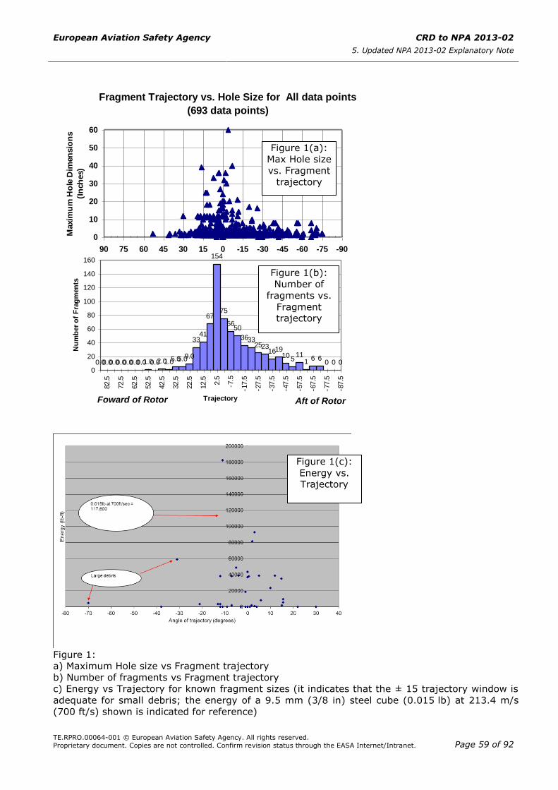
European Aviation Safety Agency CRD to NPA 2013-02
5. Updated NPA 2013-02 Explanatory Note
TE.RPRO.00064-001 © European Aviation Safety Agency. All rights reserved.
Proprietary document. Copies are not controlled. Confirm revision status through the EASA Internet/Intranet. Page 59 of 92
Figure 1:
a) Maximum Hole size vs Fragment trajectory
b) Number of fragments vs Fragment trajectory
c) Energy vs Trajectory for known fragment sizes (it indicates that the ± 15 trajectory window is
adequate for small debris; the energy of a 9.5 mm (3/8 in) steel cube (0.015 lb) at 213.4 m/s
(700 ft/s) shown is indicated for reference)
Fragment Trajectory vs. Hole Size for All data points
(693 data points)
0
10
20
30
40
50
60
-90-75-60-45-30-150153045607590
Trajectory in Degrees
Maxim
um
Ho
le D
imen
sio
ns
(In
ch
es)
Foward of Rotor Aft of Rotor
Number of Fragments by Trajectory Ranges - All data
points (693 data points)
00066
111
510
19162325
3336
5056
75
154
67
4133
9.05.05.01.02.00.01.00.00.00.00.00.00.00.00
20
40
60
80
100
120
140
160
-87.5
-77.5
-67.5
-57.5
-47.5
-37.5
-27.5
-17.5
-7.5
2.5
12.5
22.5
32.5
42.5
52.5
62.5
72.5
82.5
Trajectory
Nu
mb
er
of
Fra
gm
en
ts
Foward of Rotor Aft of Rotor
Figure 1(a):
Max Hole size
vs. Fragment
trajectory
Figure 1(b):
Number of
fragments vs.
Fragment trajectory
Figure 1(c):
Energy vs. Trajectory
European Aviation Safety Agency CRD to NPA 2013-02
5. Updated NPA 2013-02 Explanatory Note
TE.RPRO.00064-001 © European Aviation Safety Agency. All rights reserved.
Proprietary document. Copies are not controlled. Confirm revision status through the EASA Internet/Intranet. Page 60 of 92
(ref. China Lake Data)
Conclusion on Ref. 1
Ref. 1 provides data suggesting that the AMC 20-128A debris trajectories are too narrow and
should be expanded beyond ±15 degrees. Data presented in Ref. 1 does not define any
distinction between small and intermediate/large fragments, and the link between fragment
energy and trajectory does not appear to be clearly documented. However, Figure 1(c),
developed by the Rulemaking Group using the China Lake raw data, indicates that for small
debris with known energy, ± 15 degrees is adequate.
Large trajectory angles are generally associated with damage to less critical, generally thinner,
structure and debris impact energies may be reduced due to impact incidence.
The occurrence of multiple debris impact events is recognised. However, despite the conclusion
that ‘combined effects from small fragments pose the highest hazard potential to the aircraft’, the
data does not support the need for any additional actions, beyond that proposed regarding
expanded trajectories for single items of debris. Protection from a single fragment in the area
within spread angle also protects against multiple debris impacts in the same area.
Ref. 2: AIA Project Report ‘High Bypass Ratio Turbine Engine Uncontained Rotor Events and Small
Fragment Threat Characterisation 1969-2006’, Vol. 1 & 2, January 2010
Ref. 2 addresses 58 large engine uncontained events (three resulting in loss of the aeroplane),
between 1969 and 2006. AIA considered these events to have adequate information to develop
potentially useful data relating to predominately rotating part debris from HBR engines.
The objectives of Ref. 2 included developing debris detail definition and energies. (Note: Unlike in
Ref. 1 report, trajectory data was not presented.). As Ref. 1, the objectives also included the
intent to support an amendment to AC/AMC 20-128A.
In order to illustrate the limited extent of directly measureable data available, Figure 2 below
shows all Ref. 2 data points with mass information (only 30 of 445 data points) not identified as
‘intermediate’ or ‘large’ or ‘n/a’. The Ref. 2 Event ID is identified against mass (lb). It should be
noted that this figure includes debris that are beyond the definition of small debris per AMC 20-
128A (9 out of 30 have mass greater than 0.5 lb). Therefore these debris were removed prior to
performing the analysis.
Please note that a 9.5 mm (3/8 in) steel cube is of mass 0.0068 kg (0.015 lb), whilst a typical
‘small fragment’ for a large engine disk can be represented (ref. AMC 20-128A) by a debris size
up to a maximum dimension corresponding to the tip half of the blade aerofoil, which is generally
well represented in the last generation HBR engine designs by a 28 mm (1.1 in) steel cube of
0.17 kg (0.37lb). However, it is unknown how well a 28 mm (1.1 in) cube corresponds to the tip
half of the blade aerofoil for the engines involved in the incidents cited in the referenced reports.
Figure 2 shows that a 9.5 mm (3/8 in) cube (0.0068 kg (0.015 lb)) is of limited value when
addressing the threats (rotating and non-rotating) as defined by data with direct mass
information available, since only 3 of the 21 items with a recorded mass are addressed, whilst the
28 mm (1.1 in) cube (0.17 kg (0.37lb)) addresses 6 of the 21 items. Note that 9 of the 21 items
are of mass greater than 0.17 kg (0.37lb) and identified as ‘static’ or ‘large static’.
Ref. 2, Vol. 1, page 28, indicates that even if each of the 445 debris items were considered to be
of independent consequence to safety relative to the approximate total of 489 million engine
cycles during 1969-2006, then the probability of a debris item affecting safety would be
445/489E+6 = 9.1E-7 per cycle. However, each event is associated with many debris items (Ref.
1 indicates that there are about 12 debris items per event), reducing this to approximately 7.6E-8
per cycle. Furthermore, if only the three catastrophic events identified are considered, this is
reduced to approximately 6E-9. Of these, the smaller debris was not the cause of the critical
damage.
In conclusion, the probability of occurrence of these events, although low, are not sufficiently low
enough to be ignored and should be addressed.
Note (Ref. 2, Vol.1, page 28): The 530M cycle total represents the total number of cycles
completed for all engine generations (first, second, third) failures. Although it is recognised that
significant improvement has increased the reliability of later design engines, the recent
uncontained event (A380 in November 2010), combined with the sparse debris data available,
suggests that rule segregation (i.e. discussion that the latest generation of turbofan power plants
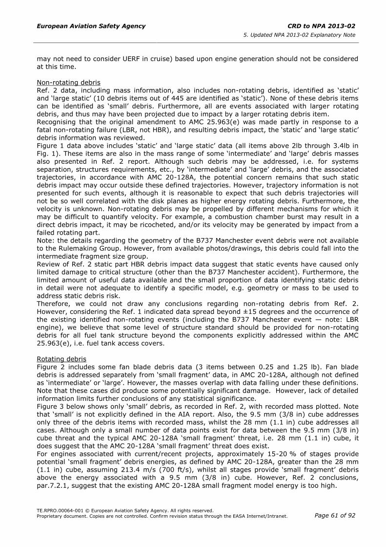
European Aviation Safety Agency CRD to NPA 2013-02
5. Updated NPA 2013-02 Explanatory Note
TE.RPRO.00064-001 © European Aviation Safety Agency. All rights reserved.
Proprietary document. Copies are not controlled. Confirm revision status through the EASA Internet/Intranet. Page 61 of 92
may not need to consider UERF in cruise) based upon engine generation should not be considered
at this time.
Non-rotating debris
Ref. 2 data, including mass information, also includes non-rotating debris, identified as ‘static’
and ‘large static’ (10 debris items out of 445 are identified as ‘static’). None of these debris items
can be identified as ‘small’ debris. Furthermore, all are events associated with larger rotating
debris, and thus may have been projected due to impact by a larger rotating debris item.
Recognising that the original amendment to AMC 25.963(e) was made partly in response to a
fatal non-rotating failure (LBR, not HBR), and resulting debris impact, the ‘static’ and ‘large static’
debris information was reviewed.
Figure 1 data above includes ‘static’ and ‘large static’ data (all items above 2lb through 3.4lb in
Fig. 1). These items are also in the mass range of some ‘intermediate’ and ‘large’ debris masses
also presented in Ref. 2 report. Although such debris may be addressed, i.e. for systems
separation, structures requirements, etc., by ‘intermediate’ and ‘large’ debris, and the associated
trajectories, in accordance with AMC 20-128A, the potential concern remains that such static
debris impact may occur outside these defined trajectories. However, trajectory information is not
presented for such events, although it is reasonable to expect that such debris trajectories will
not be so well correlated with the disk planes as higher energy rotating debris. Furthermore, the
velocity is unknown. Non-rotating debris may be propelled by different mechanisms for which it
may be difficult to quantify velocity. For example, a combustion chamber burst may result in a
direct debris impact, it may be ricocheted, and/or its velocity may be generated by impact from a
failed rotating part.
Note: the details regarding the geometry of the B737 Manchester event debris were not available
to the Rulemaking Group. However, from available photos/drawings, this debris could fall into the
intermediate fragment size group.
Review of Ref. 2 static part HBR debris impact data suggest that static events have caused only
limited damage to critical structure (other than the B737 Manchester accident). Furthermore, the
limited amount of useful data available and the small proportion of data identifying static debris
in detail were not adequate to identify a specific model, e.g. geometry or mass to be used to
address static debris risk.
Therefore, we could not draw any conclusions regarding non-rotating debris from Ref. 2.
However, considering the Ref. 1 indicated data spread beyond ±15 degrees and the occurrence of
the existing identified non-rotating events (including the B737 Manchester event — note: LBR
engine), we believe that some level of structure standard should be provided for non-rotating
debris for all fuel tank structure beyond the components explicitly addressed within the AMC
25.963(e), i.e. fuel tank access covers.
Rotating debris
Figure 2 includes some fan blade debris data (3 items between 0.25 and 1.25 lb). Fan blade
debris is addressed separately from ‘small fragment’ data, in AMC 20-128A, although not defined
as ‘intermediate’ or ‘large’. However, the masses overlap with data falling under these definitions.
Note that these cases did produce some potentially significant damage. However, lack of detailed
information limits further conclusions of any statistical significance.
Figure 3 below shows only ‘small’ debris, as recorded in Ref. 2, with recorded mass plotted. Note
that ‘small’ is not explicitly defined in the AIA report. Also, the 9.5 mm (3/8 in) cube addresses
only three of the debris items with recorded mass, whilst the 28 mm (1.1 in) cube addresses all
cases. Although only a small number of data points exist for data between the 9.5 mm (3/8 in)
cube threat and the typical AMC 20-128A ‘small fragment’ threat, i.e. 28 mm (1.1 in) cube, it
does suggest that the AMC 20-128A ‘small fragment’ threat does exist.
For engines associated with current/recent projects, approximately 15-20 % of stages provide
potential ‘small fragment’ debris energies, as defined by AMC 20-128A, greater than the 28 mm
(1.1 in) cube, assuming 213.4 m/s (700 ft/s), whilst all stages provide ‘small fragment’ debris
above the energy associated with a 9.5 mm (3/8 in) cube. However, Ref. 2 conclusions,
par.7.2.1, suggest that the existing AMC 20-128A small fragment model energy is too high.
European Aviation Safety Agency CRD to NPA 2013-02
5. Updated NPA 2013-02 Explanatory Note
TE.RPRO.00064-001 © European Aviation Safety Agency. All rights reserved.
Proprietary document. Copies are not controlled. Confirm revision status through the EASA Internet/Intranet. Page 62 of 92
Figure 2: AIA report data with mass information, not defined as ‘intermediate’, ‘large’, or ‘n/a’.
AIA Vol.2 High Bypass Debris Threat Fragment Mass (lbs) Debris with Mass Information - NOT identified as 'large', 'intermediate', or 'n/a'
0
0,5
1
1,5
2
2,5
3
3,5
4
1991
1991
1991
1991
1991
1982
A
1985
B
1985
B
1985
C
1991
1991
1991
1991
1991
1989
1989
1982
A
1982
A
1982
A
1982
A
1989
1982
A
1989
1989
1989
1992
1989
1989
2002
1985
C
1989
2006
B
1992
Event ID
Deb
ris M
ass (
lb)
3/8 in /0.015lb
1.1 in/0.37lb
All items > 2lb are
‘static’ or ‘large static’ debris

European Aviation Safety Agency CRD to NPA 2013-02
5. Updated NPA 2013-02 Explanatory Note
TE.RPRO.00064-001 © European Aviation Safety Agency. All rights reserved.
Proprietary document. Copies are not controlled. Confirm revision status through the EASA Internet/Intranet. Page 63 of 92
Figure 3: AIA report data with mass information, defined as ‘small’ (not ‘intermediate’, ‘large’,
n/a, ‘fan blade’, ‘static’, or ‘large static’).
Further to consideration of the very limited data available, evident in Figures 2 and 3, it was
considered that some value might be gained from reviewing the more recent debris data (not
defined ‘intermediate or ‘large’) with respect to the AMC defined threat, and also with respect to
some manufacturer impact test damage data. By assuming that the test impact dent or
penetration data could be correlated to the service data, when some information regarding
service debris definition, damage, and the impacted structure configuration, was available, the
number of potentially useful data points was significantly increased.
Processing of witness marks
Ref. 2, Appendix 5, detailed the witness marks left on the aeroplane by fragments, resulting from
uncontained rotating part failures. This data was processed and analysed.
An assessment of the order of magnitude of energy required to create such witness marks was
made.
This semi-empirical assessment was based upon the two following formulas. Those formulas have
been established from available low and high speed impact tests performed in the frame of recent
aircraft certification projects.
A. Dent Depth formula
From a panel thickness, this formula calculates the energy required for low speed
hemispherical impactors to create a given dent depth. The formula considers various
impact locations, i.e. middle bay, near frame, near stringer, etc.
For this evaluation, only middle bay has been used because fuel leak is the primary
concern. The underlying structure is assumed to improve the situation with respect to
such impact, these events being adequately fast to negate the need to consider
structural energy absorption through bending in the middle bay locations. This formula
was established for 1 to 6mm thick Aluminium (2024), impact normal to the plate.
As this formula has been established for lower speed hemispherical impactors, it is
anticipated that a slightly higher energy would be required to create a similar witness
mark due to high speed impact. However, sharp debris may create gouges or nicks at
a significantly lower energy than the energy required to create a dent with an
hemispherical impactor.
B. Penetration formula
AIA Vol.2 - HBR Debris Threat - 'Small' Fragment Mass
Debris w ith mass data defined 'small'
0
0,05
0,1
0,15
0,2
0,25
0,3
0,35
1991
1991
1991
1991
1991
1982
A
1985
B
1985
B
1992
1985
C
1991
1991
1991
1991
1991
1989
1989
1982
A
1982
A
1982
A
2006
B
1982
A
1982
A
1989
Event ID
De
bri
s M
ass (
lb)
1.1 in/0.37lb
3/8 in /0.015lb
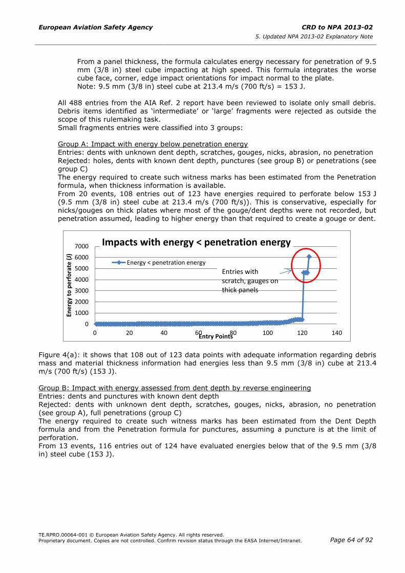
European Aviation Safety Agency CRD to NPA 2013-02
5. Updated NPA 2013-02 Explanatory Note
TE.RPRO.00064-001 © European Aviation Safety Agency. All rights reserved.
Proprietary document. Copies are not controlled. Confirm revision status through the EASA Internet/Intranet. Page 64 of 92
From a panel thickness, the formula calculates energy necessary for penetration of 9.5
mm (3/8 in) steel cube impacting at high speed. This formula integrates the worse
cube face, corner, edge impact orientations for impact normal to the plate.
Note: 9.5 mm (3/8 in) steel cube at 213.4 m/s (700 ft/s) = 153 J.
All 488 entries from the AIA Ref. 2 report have been reviewed to isolate only small debris.
Debris items identified as ‘intermediate’ or ‘large’ fragments were rejected as outside the
scope of this rulemaking task.
Small fragments entries were classified into 3 groups:
Group A: Impact with energy below penetration energy
Entries: dents with unknown dent depth, scratches, gouges, nicks, abrasion, no penetration
Rejected: holes, dents with known dent depth, punctures (see group B) or penetrations (see
group C)
The energy required to create such witness marks has been estimated from the Penetration
formula, when thickness information is available.
From 20 events, 108 entries out of 123 have energies required to perforate below 153 J
(9.5 mm (3/8 in) steel cube at 213.4 m/s (700 ft/s)). This is conservative, especially for
nicks/gouges on thick plates where most of the gouge/dent depths were not recorded, but
penetration assumed, leading to higher energy than that required to create a gouge or dent.
Figure 4(a): it shows that 108 out of 123 data points with adequate information regarding debris
mass and material thickness information had energies less than 9.5 mm (3/8 in) cube at 213.4
m/s (700 ft/s) (153 J).
Group B: Impact with energy assessed from dent depth by reverse engineering
Entries: dents and punctures with known dent depth
Rejected: dents with unknown dent depth, scratches, gouges, nicks, abrasion, no penetration
(see group A), full penetrations (group C)
The energy required to create such witness marks has been estimated from the Dent Depth
formula and from the Penetration formula for punctures, assuming a puncture is at the limit of
perforation.
From 13 events, 116 entries out of 124 have evaluated energies below that of the 9.5 mm (3/8
in) steel cube (153 J).
0
1000
2000
3000
4000
5000
6000
7000
0 20 40 60 80 100 120 140
Ene
rgy
to p
erf
ora
te (
J)
Entry Points
Impacts with energy < penetration energy
Energy < penetration energy
Entries with scratch, gauges on thick panels

European Aviation Safety Agency CRD to NPA 2013-02
5. Updated NPA 2013-02 Explanatory Note
TE.RPRO.00064-001 © European Aviation Safety Agency. All rights reserved.
Proprietary document. Copies are not controlled. Confirm revision status through the EASA Internet/Intranet. Page 65 of 92
Figure 4(b): it shows that 116 out of 124 data points with evaluated energy less than 9.5 mm
(3/8 in) cube at 213.4 m/s (700 ft/s) (153 J).
Group C: Impact with energy greater than perforation energy
Entries: holes, penetration
Rejected: all dents, scratches, gouges, nicks, abrasion, puncture (see group B)
The energy has been estimated from the Penetration formula. It represents the minimum energy
to make the hole, meaning that real energy could be much higher. From 19 events, 105 entries
out of 110 have energies lower than 153 J, but without knowledge of the maximum.
Figure 4(c): it shows that 105 out of 109 data points with impact energy lower than 9.5 mm (3/8
in) cube at 213.4 m/s (700 ft/s) (153 J).
Interpretation of these results
Group A
Only very few debris have energy evaluated > 153 J. These 15 debris items are associated with
minor damages (dent of unknown depth, gauges, nicks or abrasion) on thick panels. Therefore, it
is likely that the energy required to create such damages is far below the energy required to
penetrate.
In conclusion, all these debris items are assumed to have an energy below 153 J.
Group B
This is the group that gives better visibility regarding the energy from fragments, although the
formula used to back calculate the energy from dent was established from low speed impacts and
do not take into account possible sharp edges effects. Only 8 debris impacts have estimated
0
500
1000
1500
2000
0 20 40 60 80 100 120 140
Ene
rgy
to c
reat
e d
en
t o
r
pe
rfo
rate
(J)
Entry Points
Impacts with known energy
Known Energies
0
50
100
150
200
250
300
350
400
0 20 40 60 80 100 120
Ene
rgy
to p
erf
ora
te (
J)
Entry Points
Impacts with energy > perforation energy
Holes
European Aviation Safety Agency CRD to NPA 2013-02
5. Updated NPA 2013-02 Explanatory Note
TE.RPRO.00064-001 © European Aviation Safety Agency. All rights reserved.
Proprietary document. Copies are not controlled. Confirm revision status through the EASA Internet/Intranet. Page 66 of 92
energy above 153 J. It should be noted that conservative estimates were done when a range of
thickness was provided.
Group C
For this group, the indication of the energy required to perforate means that debris had higher
energy, but in the absence of other indications, it is difficult to conclude on the remaining energy
after penetration.
From group A and B, only 8 out of 242 fragments have energies above 153 J, confirming the
conclusions from the AIA report Vol. 1, i.e. most of the fragments have lower energy than the
existing model assumption. It also supports the use of shielding of equivalent thickness to
pressure cabin skins, as recommended in AMC 20-128A.
Available data from AIA report does not provide any information about the trajectory windows for
small debris.
Conclusion on Ref. 2
The Ref. 2 report did not present trajectory information, somewhat limiting the possible
conclusions.
However, the energy level comparison between the current AMC 25.963(e) defined threat (9.5
mm (3/8 in) steel cube at 213.4 m/s (700 ft/s) – equivalent energy = 153 J) and the service data
(by further comparison with some comparative manufacturer’s test data) was possible by
applying several assumptions.
This indicated that the existing AMC defined threat typically addresses the vast majority of debris
not defined ‘intermediate’ or ‘large’. Of the larger debris not classified as ‘intermediate’ or ‘large’,
i.e. fan blade, static, and large static items, as described in Ref. 2, inadequate data limited any
conclusions. However, no critical damages have resulted from this debris (other than the original
B737 Manchester accident).
Non-rotating debris trajectories are less well correlated with disk planes, thus requiring some
protection outside the ‘intermediate’ and ‘large’ rotating debris trajectories. This supports the
conclusions of Ref. 1. However, it also recognises, in the context of little evidence available
regarding potentially critical events having occurred, that some credit could be given for debris
impact incidence outside the already defined ‘small’, ‘intermediate’, and ‘large’ trajectories in
accordance with AMC 20-128A.
Ref. 3: DOT/FAA/AR-04/16 ‘Uncontained Engine Debris Analysis Using the Uncontained Engine
Debris Damage Assessment Model’, September 2004
Ref. 3 describes an analytical tool developed by the Naval Air Warfare Center, Weapons Division
(NAWC-WD) to evaluate the probability of hazard to an aircraft following uncontained engine
debris events. The Uncontained Engine Debris Damage Assessment Model (UEDDAM) uses the
Ref. 1 China Lake data as debris fragment model inputs and is presented in Ref. 3 with two
hypothetical examples, i.e. a generic business jet and a generic twin-engine aircraft, to establish
the aircraft level hazard. The tool generates a hazard probability output and provides details of
critical component contributions for each Monte Carlo iteration, and/or a tabulation of risk angles
for each critical component per event. Ref. 3 concludes that UEDDAM can provide early insight
into the rotor burst hazard.
Conclusion on Ref. 3
The UEDDAM could provide a potentially very useful design tool, and this could contribute to the
Certification process. However, the level of proposed refinement in the model requires review in
the context of the very limited input data available, the necessary assumptions, and the use of
probabilistic methods in general.
The Rulemaking Group did not have the resources available to investigate UEDDAM further during
this review cycle, the main objective being to define the threat model, not to select a tool.
However, the review of UEDDAM could form part of a future rulemaking activity, possibly
including the preparation for a revision to AC/AMC 20-128A. This review process, and amendment
as appropriate, should include both input from the creators of the model and recent data, e.g.
European Aviation Safety Agency CRD to NPA 2013-02
5. Updated NPA 2013-02 Explanatory Note
TE.RPRO.00064-001 © European Aviation Safety Agency. All rights reserved.
Proprietary document. Copies are not controlled. Confirm revision status through the EASA Internet/Intranet. Page 67 of 92
AIA Ref. 2 at Phase II when completed, provided that it includes the appropriate data (e.g.
trajectories).
Further to the recommendations in Ref. 3, it is suggested that, if industry sees potential in using
this tool, aircraft manufacturers should exercise UEDDAM using appropriate personnel, thus
gaining experience and allowing development of the proposed analysis guidelines. Such an
activity may support, or otherwise, the potential acceptance of UEDDAM.
18. Material change: composite materials
Recent projects have significantly extended the use of composite materials into critical structure
applications, including fuel tanks, which are commonly recognised to be exposed to potentially
significant impact threats.
As discussed within recent Certification Review Items (CRIs) associated to composite fuel tank
structure, the existing ‘acceptable’ level of safety relating to engine debris impact has been
provided by experience with metallic structure, partly defined by design drivers other than
impact, and which have not been specifically tested for engine debris impact. Therefore,
considering the different engineering property values, and behaviours, which exist between
metallic and composite materials, particularly those relating to impact behaviour, the material
change cannot be assumed to provide the existing ‘acceptable’ level of safety.
In the absence of a review of impact threats and a validated threat model, recent projects have
been subject to CRIs. These require ‘equivalence’ of penetration resistance to be shown between
‘composite’ and existing ‘metallic’ structure for several impactors, recognising composite
sensitivity to impactor configuration, stiffness, etc.
These CRIs offer three basic options:
— show that all skin will not be penetrated by any defined threat;
— show ‘equivalence’ by reference to an agreed metallic comparative structure; and
— a combination of the above.
Further to the threat review reported above, and the experience of recent programmes, the
proposed small debris threat, although defined by very limited data, is adequately defined for the
purposes of the proposed AMC.
From a structures perspective, the primary concern relating to uncontained engine debris has
been that of Residual Strength relating to ‘intermediate’ and ‘large’ debris. Although such debris
is considered for more restricted spread angles than is considered for the existing small debris
threat (ref. AMC 20-128A), it is noted that there would appear to have been no serious structural
outcomes resulting specifically from small debris, or even slightly larger debris, outside the ± 15
degrees spread angle.
Furthermore, other Fatigue and Damage Tolerance (F&DT) considerations are not a primary
concern because such events are annunciated and the resulting debris tends to be both sharp and
hard, resulting in visible damage. Such behaviour for the current generation of materials are
supported by a growing body of data. The longer term F&DT concern is further reduced by the
need for such uncontained engine events to be followed by thorough internal and external
inspections.
From a systems perspective, the potential for leak resulting from such damage is more broadly
addressed by the proposed amendment requiring consideration of impact beyond ± 15 degrees
(rearward of the engine) with no resulting hazardous fuel leak.
Material change — conclusion
Considering the discussion above, the proposed amendment to the AMC 25.963(e) defined small
engine debris threat is adequate from a structures and fuel systems perspective relative to the
existing experience with the current generation of composite materials. However, in order to
address potential material and configuration changes, a guidance material text is added to ensure
that any variability in properties, or configuration, e.g. due to competing failure modes, is

European Aviation Safety Agency CRD to NPA 2013-02
5. Updated NPA 2013-02 Explanatory Note
TE.RPRO.00064-001 © European Aviation Safety Agency. All rights reserved.
Proprietary document. Copies are not controlled. Confirm revision status through the EASA Internet/Intranet. Page 68 of 92
detected: impact tests should be completed in adequate number to show repeatable stable
localised damage modes and damage extents for all impactor orientations (side-on, edge-on, and
corner-on).
This is considered to be a reasonable addition, recognising that this proposal is associated with
removal of the ‘equivalence’ based CRIs requiring testing using several impactors.
19. Small engine debris: conclusion and proposal for CS-25 amendment
It is proposed to amend CS 25.963(e) and AMC 25.963(e) for protection of fuel tanks against the
risk of hazardous fuel leakages from small engine debris threat. Therefore, the applicability of the
amended CS 25.963(e) is not anymore limited to fuel tank access covers.
The proposed AMC 25.963(e) defines the small engine debris threat as a 9.5 mm (3/8 in steel
cube at 213.4 m/s (700 ft/s). This model of threat is the same as the current AMC for the
evaluation of fuel tanks access covers.
The applicability of this threat includes the ± 15 degrees area of the engine for which a normal
impact to the skin is to be considered. It further adds the need to consider expanded trajectories
between -15 and -45 degrees rearward of the engine, allowing credit for impact incidence angle;
the threat area expansion is limited to the zone where we found most of the fragments and also
the most significant damages (refer to Figure 1 above).
In addition, pass-fail criteria are provided to support the demonstration that no hazardous fuel
leak will be created. This proposal is similar to the pass-fail criteria that has been used for
protection against the risk of fuel leakage from small tyre debris impact on recent CRIs/IPs
applied to certification projects. These criteria were used and accepted within the Airbus A350
CRI C-05 (Tyre Debris vs. Fuel Leakage for CFRP Fuel Tank), B787 CRI C-13 (Tyre/Wheel Debris
– Fuel Tank Penetration), B787 IP P-21 (Tire Failure – Debris Penetration or Rupture of Fuel Tank
Structure).The intent is to prevent a leak that will run or drip from the fuel tank surface. The
criteria of the IP/CRI were defined based on the Boeing Airplane Maintenance Manual (section 28-
11-00) definitions of fuel leaks which are divided into four groups as follows:
“(1) Fuel leakage is divided into four groups to calculate flight safety.
NOTE: The dimension patterns of fuel leaks are based on an examination 15 minutes after the
leak area was rubbed clean.
(a) A stain is a leak where the wetted area is not more than 1 ½ inches wide after the time
interval noted above.
(b) A seep is a leak where the wetted area is not more than 4 inches wide after the time
interval noted above.
(c) A heavy seep is a leak where the wetted area is not larger than 6 inches wide after the time
interval noted above.
(d) A running leak is all fuel leaks that are larger than 6 inches wide after the time interval
noted above.
NOTE: Fuel will usually come into view again immediately after being wiped dry and can run or
drip from the surface.”
The ‘heavy seep’ group was therefore considered as the reference for defining a hazardous fuel
leak.
These criteria have been used by Boeing since the 707 aeroplane models (i.e. since 1959) and
are considered to be safe based on in-service experience.
The guidance material also recommends that any significant variability in structural response is
detected and addressed accordingly. The proposed text is intended to help uncover other
potentially significant competing damage modes (e.g. disbond, etc.).
European Aviation Safety Agency CRD to NPA 2013-02
5. Updated NPA 2013-02 Explanatory Note
TE.RPRO.00064-001 © European Aviation Safety Agency. All rights reserved.
Proprietary document. Copies are not controlled. Confirm revision status through the EASA Internet/Intranet. Page 69 of 92
The proposed small engine debris threat model is identical to the one provided in current AMC
25.963(e), except that it will be used to evaluate the fuel tanks, not only fuel tank access covers.
The advantage of this proposal is that it would set a standardised threat model protecting the fuel
tank from engine non-rotating debris, small rotating debris, and ricochets. Then this threat would
be usable for both metallic and composite fuel tank material. This will facilitate the assessment of
aeroplanes making use of composite fuel tanks which cannot be compared in terms of impact
resistance to a predecessor metallic fuel tank aeroplane for demonstrating an equivalent or
superior level of safety (as was performed on some recent projects through the CRI process).
The expansion of the applicability of the threat model beyond the ± 15 degrees fuel tank access
covers is not expected to create additional cost or weight impact for new CS-25 large aeroplane
designs. Indeed, it is recognized that the wing skin surrounding fuel tank access covers is
designed to carry main wing loads and therefore this typically drives its impact resistance
capability beyond the level required to resist the 9.5 mm (3/8 in) cube threat.
20. Recommendation for future rulemaking
The next review of the engine debris threat should consider the following:
— AIA Phase II activities (when complete, see Ref. 2);
— thorough review of the FAA UEDDAM tool (see Ref. 3), and consideration of its acceptability,
or similar statistical approaches for inclusion/identification within AMC material; and
— review of any newly gained service experience of small engine debris impact of composite
structures, particularly fuel tanks.
VII. Tyre and wheel debris
21. References
1. Responses from manufacturers (large aeroplane, wheel, tyre) to EASA letter requesting
data on wheel and tyre failure related events.
2. Boeing presentation to the Rulemaking Group of their studies to define a radial tyre
burst pressure plume.
3. JAA Administrative & Guidance Material — Section Three: Certification — Part 3: Interim
Policies & Temporary Guidance Material: TGM/25/08 ‘Wheel and Tyre Failure Model’,
Issue 2, dated 1.6.2002.
4. Accident to the Concorde registered F-BTSC on 25 July 2000 at La Patte d’Oie in
Gonesse, France (Source report — BEA f-sc000725a).
5. Accident to Bombardier Learjet 60 registered N999LJ on 19 September 2008 at
Columbia Metropolitan Airport, South Carolina, USA (Source Report — NTSB report
AAR10-02).
6. Incident to Boeing 747-200 registered EC-DIA, on 1 February 1999 in Madrid Airport
Barajas, Spain (Comisión de Investigación de Accidentes e Incidentes de Aviación Civil
(CIAIAC), Spain, Boletin Informativo 1/99, item IN-004/99).
7. Incident to Boeing 747-200F registered N516MC on 16 July 2006 in Amsterdam, the
Netherlands (Dutch Safety Board (Onderzoeksraad voor Veiligheid) — Occurrence
number: 2006086).
8. Accident to Lockheed L-1011-200 registered HZ-AHJ on 23 December 1980 over
international waters near the State of Qatar (flight SV162) (source: NTSB Safety
Recommendations A-81-001).
9. Accident to Boeing 747-122 registration N4714U in Honolulu (USA) on 16 November
1984 (source NTSB Id: DCA85AA003).
10. Incident to Bombardier BD700 GX on 9 December 2005, Report:
ASC-AOR-07-01-001 dated 25 January 2007, Aviation Safety Council Taipei, Taiwan.
11. Incident to Bombardier BD700 GX on 29 January 2008, Report: AAIB Bulletin 12/2008.

European Aviation Safety Agency CRD to NPA 2013-02
5. Updated NPA 2013-02 Explanatory Note
TE.RPRO.00064-001 © European Aviation Safety Agency. All rights reserved.
Proprietary document. Copies are not controlled. Confirm revision status through the EASA Internet/Intranet. Page 70 of 92
22. Scope
The Rulemaking Group collected and assessed available data relating to large aeroplane damage
caused by debris coming from tyre and wheel failure events.
A review of existing related CS-25 provisions was also performed, as well as existing Certification
Review Items (CRIs) and industry design practices.
Based on this work, the NPA proposed an amendment of CS-25 which includes the creation of a
new rule dedicated to these threats and a corresponding model proposed as an AMC which
provides models of the threats and the expected criteria for protection of the aircraft structure
and systems. Existing related paragraphs are amended.
23. Background
Although the threat from wheel and tyre failure is identified by CS 25.729(f), CS 25.963(e) and
CS 25.1309, it has not been quantified in the CS-25 AMC material.
Until the publication of a JAA Temporary Guidance Material (TGM) early in 2000, each project, or
applicant, had proposed an individual model of the threat which inevitably lead to inconsistencies
of interpretation of the threat. Over the following two years, this TGM was only slightly modified,
and the final version was published as TGM/25/08, issue 2, dated 1 June 2002 (TGM —
Temporary Guidance Material).
The TGM model was developed by JAA early in 2000. It was based on the A320 model from
Airbus, which resulted from a BAE study of worldwide events data.
Airbus also updated their model to remove the probabilistic approach and also to bring some
clarifications compared to the TGM model.
The TGM model provides failure modes for the following threats:
— tyre burst: Gear extended (tyre tread debris), gear retracted (blast effects),
— flailing tread: Gear extended and gear retracting or retracted (strip of loose tread rotating
with the wheel), and
— wheel rim release: Gear extended (wheel rim pieces projection) and gear retracted
(complete rim release, for braked wheel).
The history of TGM/25/08 between its initiation and final publication could not be traced.
Following publication of the TGM, it has been widely applied on European projects, and on many
international projects too. On projects where the JAA and later EASA were involved, it has been
introduced via a Certification Review Item (CRI) as advisory or interpretative material in order to
show compliance with the identified requirements (CS 25.729(f) and CS 25.1309). A few
manufacturers used the model without modification. However, the majority proposed their own
models either as substitutes for, or in addition to, the TGM.
A second smaller tyre debris model and an amendment to paragraph 14CFR25.963(e) were
published by the FAA. The model was put in AC 25.963-1 in 1992 and was subsequently
introduced by EASA in AMC 25.963(e) through CS-25 Amendment 3, as a result of NPA 21/2005
(previously, this material was prepared under JAA organisation (NPA 25E-304) after the ARAC
General Structures Harmonisation Working Group (GSHWG) produced their report in June 2000).
This group considered tyre impacts on fuel tank access covers and allowed either a rational model
proposed by the applicant or a model comprising 1 % tyre mass impacting over an area of 1.5 %
of the total tread area impacting 30 degrees inboard and outboard of the tyre plane of rotation.
The objective of the Working Group was to propose a single model that could be used to assess
any structure or system on the aircraft. The TGM model was considered as a baseline model
which would then be amended after consideration of in-service events and past relevant
certification and design practices.
24. Existing related CS-25 provisions
‘CS 25.729 Retracting mechanism
...
(f) Protection of equipment on landing gear and in wheel wells. Equipment that is essential
to the safe operation of the aeroplane and that is located on the landing gear and in wheel
wells must be protected from the damaging effects of —
(1) A bursting tyre;
European Aviation Safety Agency CRD to NPA 2013-02
5. Updated NPA 2013-02 Explanatory Note
TE.RPRO.00064-001 © European Aviation Safety Agency. All rights reserved.
Proprietary document. Copies are not controlled. Confirm revision status through the EASA Internet/Intranet. Page 71 of 92
(2) A loose tyre tread unless it is shown that a loose tyre tread cannot cause
damage; and
(3) Possible wheel brake temperatures.
...
AMC 25.729
Retracting Mechanism
...
4. DISCUSSION.
...
d. Protection of equipment on landing gear and in wheel wells. (Reference CS 25.729(f)
Protection of equipment on landing gear and in wheel wells)
The use of fusible plugs in the wheels is not a complete safeguard against damage due
to tyre explosion.
Where brake overheating could be damaging to the structure of, or equipment in, the
wheel wells, an indication of brake temperature should be provided to warn the pilot.
...
CS 25.963 Fuel tanks: general
...
(e) Fuel tank access covers must comply with the following criteria in order to avoid
loss of hazardous quantities of fuel:
(1) All covers located in an area where experience or analysis indicates a strike is
likely, must be shown by analysis or tests to minimise penetration and deformation
by tyre fragments, low energy engine debris, or other likely debris.
...
AMC 25.963(e)
Fuel Tank Access Covers
...
3. IMPACT RESISTANCE.
a. All fuel tanks access covers must be designed to minimise penetration and
deformation by tyre fragments, low energy engine debris, or other likely debris, unless
the covers are located in an area where service experience or analysis indicates a strike
is not likely. The rule does not specify rigid standards for impact resistance because of
the wide range of likely debris which could impact the covers. The applicant should,
however, choose to minimise penetration and deformation by analysis or test of covers
using debris of a type, size, trajectory and velocity that represents conditions
anticipated in actual service for the aeroplane model involved. There should be no
hazardous quantity of fuel leakage after impact. It may not be practical or even
necessary to provide access covers with properties which are identical to those of the
adjacent skin panels since the panels usually vary in thickness from station to station
and may, at certain stations, have impact resistance in excess of that needed for any
likely impact. The access covers, however, need not be more impact resistant than the
average thickness of the adjacent tank structure at the same location, had it been
designed without access covers. In the case of resistance to tyre debris, this
comparison should be shown by tests or analysis supported by test.
b. In the absence of a more rational method, the following may be used for evaluating
access covers for impact resistance to tyre and engine debris.

European Aviation Safety Agency CRD to NPA 2013-02
5. Updated NPA 2013-02 Explanatory Note
TE.RPRO.00064-001 © European Aviation Safety Agency. All rights reserved.
Proprietary document. Copies are not controlled. Confirm revision status through the EASA Internet/Intranet. Page 72 of 92
(i) Tyre Debris Covers located within 30 degrees inboard and outboard of the tyre plane
of rotation, measured from centre of tyre rotation with the gear in the down and locked
position and the oleo strut in the nominal position, should be evaluated. The evaluation
should be based on the results of impact tests using tyre tread segments equal to
1 per cent of the tyre mass distributed over an impact area equal to 1.5 per cent of the
total tread area. The velocities used in the assessment should be based on the highest
speed that the aircraft is likely to use on the ground under normal operation.’
25. JAA TGM/25/08 Issue 2
The TGM model is provided in Appendix 1 to NPA 2013-02.
26. Review of tyre and wheel failure events data
General
The Working Group searched relevant data relating to tyre and wheel failures in service.
CS-25 large aeroplane accident/incident investigation reports were gathered and analysed.
In addition, request letters were sent to large aeroplane manufacturers, wheel and brake
manufacturers and tyre manufacturers. The recipients were provided with a table which
included various fields for assessing debris characteristics, consequences of failures on
structure and systems, and also questions related to eventual use of a tyre and wheel
failure model for type certification.
An example of this table for tyre debris is provided below: TYRE DEBRIS
27. Review of tyre and wheel failure events data
General
The Working Group searched relevant data relating to tyre and wheel failures in service.
CS-25 large aeroplane accident/incident investigation reports were gathered and analysed.
In addition, request letters were sent to large aeroplane manufacturers, wheel and brake
manufacturers and tyre manufacturers. The recipients were provided with a table which
included various fields for assessing debris characteristics, consequences of failures on
structure and systems, and also questions related to eventual use of a tyre and wheel
failure model for type certification.
28. Review of tyre and wheel failure events data
General
The Working Group searched relevant data relating to tyre and wheel failures in service.
CS-25 large aeroplane accident/incident investigation reports were gathered and analysed.
In addition, request letters were sent to large aeroplane manufacturers, wheel and brake
manufacturers and tyre manufacturers. The recipients were provided with a table which
included various fields for assessing debris characteristics, consequences of failures on
structure and systems, and also questions related to eventual use of a tyre and wheel
failure model for type certification.
An example of this table for tyre debris is provided below:
TYRE DEBRIS
Aeroplane type
Date of the event
Dimensions of debris (number of fragments with
associated length, width, thickness)
Number of tyres affected?
Adjacent or companion on same axle?
Type of tyre affected (radial or new generation or bias)
New tyre or re-tread level?
Main gear or nose gear?
Phase of flight
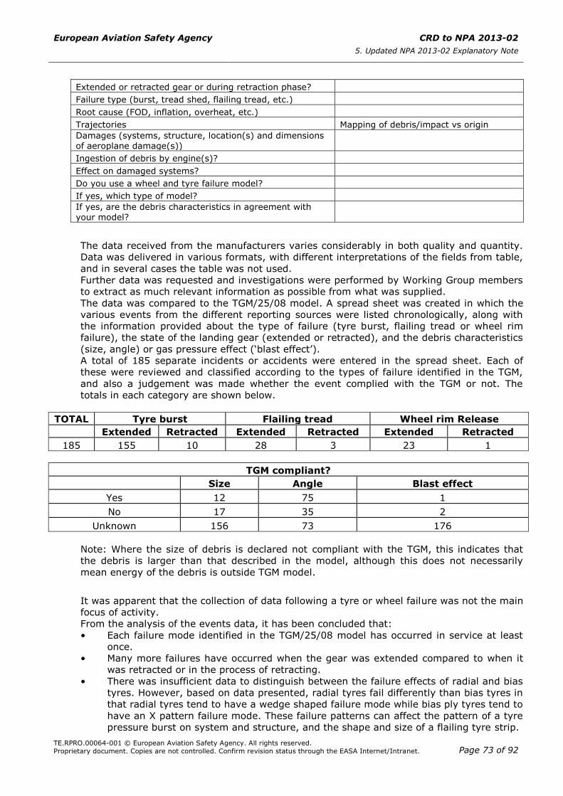
European Aviation Safety Agency CRD to NPA 2013-02
5. Updated NPA 2013-02 Explanatory Note
TE.RPRO.00064-001 © European Aviation Safety Agency. All rights reserved.
Proprietary document. Copies are not controlled. Confirm revision status through the EASA Internet/Intranet. Page 73 of 92
Extended or retracted gear or during retraction phase?
Failure type (burst, tread shed, flailing tread, etc.)
Root cause (FOD, inflation, overheat, etc.)
Trajectories Mapping of debris/impact vs origin
Damages (systems, structure, location(s) and dimensions of aeroplane damage(s))
Ingestion of debris by engine(s)?
Effect on damaged systems?
Do you use a wheel and tyre failure model?
If yes, which type of model?
If yes, are the debris characteristics in agreement with your model?
The data received from the manufacturers varies considerably in both quality and quantity.
Data was delivered in various formats, with different interpretations of the fields from table,
and in several cases the table was not used.
Further data was requested and investigations were performed by Working Group members
to extract as much relevant information as possible from what was supplied.
The data was compared to the TGM/25/08 model. A spread sheet was created in which the
various events from the different reporting sources were listed chronologically, along with
the information provided about the type of failure (tyre burst, flailing tread or wheel rim
failure), the state of the landing gear (extended or retracted), and the debris characteristics
(size, angle) or gas pressure effect (‘blast effect’).
A total of 185 separate incidents or accidents were entered in the spread sheet. Each of
these were reviewed and classified according to the types of failure identified in the TGM,
and also a judgement was made whether the event complied with the TGM or not. The
totals in each category are shown below.
TOTAL Tyre burst Flailing tread Wheel rim Release
Extended Retracted Extended Retracted Extended Retracted
185 155 10 28 3 23 1
TGM compliant?
Size Angle Blast effect
Yes 12 75 1
No 17 35 2
Unknown 156 73 176
Note: Where the size of debris is declared not compliant with the TGM, this indicates that
the debris is larger than that described in the model, although this does not necessarily
mean energy of the debris is outside TGM model.
It was apparent that the collection of data following a tyre or wheel failure was not the main
focus of activity.
From the analysis of the events data, it has been concluded that:
• Each failure mode identified in the TGM/25/08 model has occurred in service at least
once.
• Many more failures have occurred when the gear was extended compared to when it
was retracted or in the process of retracting.
• There was insufficient data to distinguish between the failure effects of radial and bias
tyres. However, based on data presented, radial tyres fail differently than bias tyres in
that radial tyres tend to have a wedge shaped failure mode while bias ply tyres tend to
have an X pattern failure mode. These failure patterns can affect the pattern of a tyre
pressure burst on system and structure, and the shape and size of a flailing tyre strip.
European Aviation Safety Agency CRD to NPA 2013-02
5. Updated NPA 2013-02 Explanatory Note
TE.RPRO.00064-001 © European Aviation Safety Agency. All rights reserved.
Proprietary document. Copies are not controlled. Confirm revision status through the EASA Internet/Intranet. Page 74 of 92
• There were no noticeable differences in the failure modes recorded for re-treaded
tyres.
• It was rare that damage to an aircraft could be correlated with the debris that caused
the damage.
• In many cases evidence of debris impact was outside the areas defined by the TGM.
However, no impact energy could be derived for these pieces because the debris could
not be identified. This is why the group recommends maintaining the current region of
vulnerability for the larger debris pieces, and extending the region of vulnerability for
only the smaller pieces.
• Multiple tyre bursts did occur.
• There were cases of multiple fragments of tread thrown from a single tyre. In one
case multiple fragments appear to have been directly linked to an accident.
• The single retracted wheel flange failure which occurred in service was not considered
to be relevant. Please refer to event 4) below.
The cases of vertical wheel flange debris release (gear extended) were considered to
be enveloped by the tyre debris threat model, and therefore it is proposed not to
characterise this threat in our model. See further explanations on this point below.
Many events reports did not permit retrieving important parameters like debris size,
speed, damage. Consequently, the events where this information was available were
carefully analysed and used to challenge the TGM model. Some events are commented
in the following paragraph.
Analysis of some events with key elements
This section describes in more detail certain important events which are key when
considering either change to or maintaining the model.
1) Accident to the Concorde registered F-BTSC on 25 July 2000 at La Patte d’Oie in
Gonesse, France (Source report — BEA f-sc000725a)
Summary:
The aircraft ran over a piece of runway foreign object debris which initiated a tyre
failure. The tyre failure ‘in all probability resulted in large pieces of rubber being
thrown against the underside of the left wing … a severe fire broke out under the left
wing’. The tyre impact would have induced a complex failure mode (‘a hydrodynamic
pressure surge’) in the tank which would account for the separation of a section of the
tank lower surface which was found on the runway. It had ‘suffered pressure directed
from the inside of the tank towards the outside, causing it to rupture’.
The tyre debris was collected and pieces were found weighing up to 4.5 kg
(100*33 cm).
In the research and tests conducted during the preparation of the accident
investigation report, similarity was demonstrated to the damage, with clean cuts,
when the tyre runs over a representative cutting object at various speeds. The tyres
were systematically cut right through and burst, releasing pieces of significant weight
and size.
Parameters Affecting Model:
The TGM model considers two sizes of debris − large (W × W) and small (W/2 × W/2)
with ‘W’ being the width of the tyre and with the thickness defined only as ‘full tread
thickness’. The Concorde accident and other incidents/accidents confirmed that large
pieces of debris need to be considered as debris threat.
The dimensions of the Concorde main wheel tyre was 47 × 15.75-22.1 inches.
The tyre maximum weight was 105.0 kg.
1 % of tyre mass would be 1.05 kg.
Mass of a W × W piece of tyre − full carcass thickness = 6.06 Kg
Mass of W ×W piece of tyre − tread only = 2.103 kg
Mass of W × W piece of tyre − tread + protector ply = 2.24 kg
European Aviation Safety Agency CRD to NPA 2013-02
5. Updated NPA 2013-02 Explanatory Note
TE.RPRO.00064-001 © European Aviation Safety Agency. All rights reserved.
Proprietary document. Copies are not controlled. Confirm revision status through the EASA Internet/Intranet. Page 75 of 92
The above calculated masses were included to demonstrate that none of the debris
sizes currently modelled would have approximated to the size of debris thought to
have contributed to this accident. Three would have been too small, and one too large.
Although some of the circumstances of this accident are peculiar to the design of the
aircraft involved (which is specific to the Concorde and does not reflect the design of
subsonic airliners), some aspects can be read across to all aircraft.
This accident confirms that tyres can be destroyed by foreign object damage (FOD) on
the runway.
This accident shows that a hydrodynamic pressure failure mode exists, and the
Working Group concluded that this should be specifically mentioned in the model.
2) Accident to Bombardier Learjet 60 registered N999LJ on 19 September 2008
at Columbia Metropolitan Airport, South Carolina, USA (Source Report — NTSB report
AAR10-02)
Multiple tyre failures.
Summary:
In September 2008 a Learjet 60 with 8 persons on board aborted the take-off above
the V1 speed following multiple tyre failures due to severe tyres under-inflation. The
tyres failures also caused failures in several aircraft systems, including some
associated with aircraft retardation. These systems were not adequately protected or
segregated.
Parameters Affecting Model:
This accident confirms the need to assess multiple tyre failures in the model, that a
thorough review of critical system components in the tyre burst zones is necessary,
and also confirms that one of the major causes of tyre failure is under-inflation.
3) Two Boeing 747 incidents
Vertical release of wheel rim debris.
(i) Boeing 747-200 registered EC-DIA on 1 February 1999 in Madrid Airport Barajas,
Spain (Comisión de Investigación de Accidentes e Incidentes de Aviación Civil
(CIAIAC), Spain, Boletin Informativo 1/99, item IN-004/99)
Summary:
Vertical wheel rim debris during take-off, when the aircraft reached 130 knots. It
was observed that the ‘landing gear not centered’ light came on. After lift-off, it
was detected that the landing gear did not retract, and a loss in hydraulic system
No 1 was observed. It was communicated that, during take-off, something had
struck the passenger cabin opening a hole near the 37th row. Next, a loss in
hydraulic system No 4 was identified, which was able to be stopped. Finally,
emergency procedures were executed, fuel dumped, and the aircraft landed back
at Madrid.
(ii) Boeing 747-200F registered N516MC on 16 July 2006 in Amsterdam, the
Netherlands (Dutch Safety Board (Onderzoeksraad voor Veiligheid) —
Occurrence number: 2006086)
Summary:
Vertical wheel rim debris — On 16 July 2006, a Boeing 747-200F, N516MC,
operated by Atlas Air, suffered minor damage when the left main body gear tyre
burst during take-off from runway 36L at Amsterdam/Schiphol Airport. The
aeroplane returned to the airport and landed on runway 06. The damaged flap
system caused a flap asymmetry and roll movement. The fuselage was damaged
by the wheel and tyre fragments. The three crew members were not injured.
Analysis:
— The two events above are the only cases found by the Working Group, involving
vertical release of wheel debris. In both cases, the aircraft completed take-off
and performed a safe landing. The length of the involved flange debris at the
Madrid event are unknown, however, it is known that the debris entered the
passenger cabin. The debris from the Amsterdam event included at least a
European Aviation Safety Agency CRD to NPA 2013-02
5. Updated NPA 2013-02 Explanatory Note
TE.RPRO.00064-001 © European Aviation Safety Agency. All rights reserved.
Proprietary document. Copies are not controlled. Confirm revision status through the EASA Internet/Intranet. Page 76 of 92
flange arc around 120° which perforated the MLG bay structure (estimation from
a photo).
— The level of energy of a wheel flange debris between 60 and 120° of arc is
estimated to be less than or equal to the one of a small tyre debris as defined in
our proposed model (Model 1). So the small tyre debris model requirement
would also provide some protection against wheel flange debris.
— In term of system protection (i.e. separation), the large tyre debris W × W of
our proposed model would protect against 120° flange debris, as the diagonal of
the W × W debris contains the 120° flange arc for the typical wheel/tyre
combinations. The Working Group particularly assessed it for the Bombardier
CRJ-1000 and Boeing 747-8.
— Regarding the fuel leak risk, we consider the W × W debris hole as enveloping
any threat coming from wheel flange debris.
Parameters Affecting Model:
Based on this, it is decided not to propose an explicit flange debris threat in the
vertical area. Although a flange debris is not explicitly defined, it is considered that the
small tyre debris calculation provided an equivalent energy level to that of the wheel
flange debris.
The group also made the following comparison: a 60° flange arc is smaller than a
W × W tyre debris for A320, A330, DHC-8.
4) Accident to Lockheed L-1011-200 registered HZ-AHJ on 23 December 1980 over
international waters near the State of Qatar (flight SV162) (source: NTSB Safety
Recommendations A-81-001)
Wheel flange debris release with gear retracted.
Summary:
Flight SV162 experienced an explosive decompression of the cabin while climbing
through 29,000 feet over international waters near the State of Qatar. The aircraft had
departed Dhahran, Saudi Arabia, and was en-route to Karachi, Pakistan. An
emergency descent was initiated and a successful landing was made at Doha
International Airport in Qatar. Two passengers were killed when they were ejected
from the aircraft through a hole in the cabin floor which had resulted from the forces
of explosive decompression. Probable cause: ‘The Presidency of Civil Aviation
determines that the probable cause of this accident was an in-flight, fatigue failure of
a main landing gear inboard wheel flange resulting in the rupture of the aircraft's
pressure hull and explosive decompression. The failure of the flange, was the result of
the failure of the B.F. Goodrich Company and the Lockheed Aircraft Company to
properly assess the safety hazard associated with the type of wheels installed on
aircraft HZ-AHJ. Contributing to the accident was the lapse of effective quality control
procedures by the B.F. Goodrich Company and the failure of the Federal Aviation
Administration to provide adequate surveillance of the manufacturer.’
Analysis:
After this event, the TSO for wheel and brakes was updated by adding a new
requirement to demonstrate a roll-on-rim capability. This required the flange being
reinforced and therefore increased the integrity of the wheel and made it more
tolerant to fatigue failure mode. Since then we found no similar event that occurred
with the gear retracted.
Parameters Affecting Model:
It is concluded that current TSO/ETSO for wheel and brakes sufficiently protects
against this kind of risk, and therefore it is decided to restrict this threat to the gear
extended configuration.
5) Accident to Boeing 747-122 registration N4714U in Honolulu (USA) on 16 November
1984 (source NTSB Id: DCA85AA003)
Summary:
After accelerating to about 153 kts during the take-off roll, the No 7 tyre failed and
the crew aborted the take-off. An investigation revealed the No 7 tyre had failed after
European Aviation Safety Agency CRD to NPA 2013-02
5. Updated NPA 2013-02 Explanatory Note
TE.RPRO.00064-001 © European Aviation Safety Agency. All rights reserved.
Proprietary document. Copies are not controlled. Confirm revision status through the EASA Internet/Intranet. Page 77 of 92
the inner bearing of that wheel had failed. This caused the wheel and tyre to overheat,
which allowed the fuses to melt and blow out. The reason for the bearing failure was
not verified. A tyre fragment penetrated a fuel tank access panel on the right wing.
Large quantities of fuel were spilled but never ignited.
Analysis:
The ability of a relatively low speed tyre failure fragment to penetrate any part of the
wing should have been recognised as a potentially hazardous condition.
Parameters Affecting Model:
This incident led to the introduction of the 1 % tyre mass/1.5 % tread area model
used in the revision of AC 25.963-1 and present today in AMC 25.963(e). However,
this rule and advisory material were only made applicable to fuel tank access covers.
The Working Group believes that there is no valid reason for not making this same
impact model applicable also to the remainder of the fuel tank.
6) Bombardier Global Express BD700 events
(i) Event date: 09 December 2005
Report: ASC-AOR-07-01-001 dated 25 January 2007, Aviation Safety Council
(ASC) Taipei, Taiwan.
Summary:
The aircraft departed Taipei and landed in Taiwan Kaohsiung airport. Upon
landing failure indications for thrust reversers, hydraulic systems #2 and #3
were recorded. Also, the crew noted loss of nose wheel steering, and the aircraft
drifted right and off the runway onto the adjacent grass area. The left inboard
MLG tyre was damaged by a deep skid from a locked wheel during landing.
Subsequently, the tyre failed and the tyre flail damaged wing substructure
(broken), hydraulic systems #2 and #3 tubes (ruptured), flap torque tube
(shattered), flap and spoiler harnesses in the aux spar area, and there was
localised wing structural damage. The locked wheel and skid was a result of
contamination of a brake control valve. Subsequently, Bombardier issued an
Advisory Wire AW600-32-2265. Tyre debris dimensions included three pieces
< 1.5”L × 3.0”W × 0.75”D. In addition, and of particular interest was a tyre flail
dimension of 19.6”L × 17”W × 0.75”D including both tread and carcass. The
aircraft MLG tyre was a bias ply 38 × 12 × 19 (Outer Diameter × Width × Rim
Diameter). No injuries recorded.
Analysis:
The investigation report is included in its Appendix 4, Bombardier Engineering
Document No RBS-C700-108, which analysed this event and included the
following statements.
Paragraph 5.1.5:
‘A review of the tire failure, and projected shedding of radial trajectories,
excludes direct impact striking of components nestled in the rear spar area. It
also strongly suggests that a rotation of a flailing tire is required for the level,
and type of damage observed on system installations in that area.
The evidence indicating that some of the components (flap torque tube, wiring,
hydraulic lines, and sheet metal shield) were "pulled down and out" by a rotating
tire piece, as opposed to being "pushed in" by trajectory impact, is noted here
for reference (Photo 2). Additionally, the black rubbing mark on the inboard flap,
suggesting flailing tire contact must be mentioned.’
Paragraph 8.0 Conclusions, includes:
‘1. The cause of the Aircraft 9009 landing incident on Dec 9th, 2005 at Taiwan
Kaohsiung airport, was the failure of #2 MLG tire after touch down, causing
flailing tire damage to the aircraft hydraulics and flight control systems.’
This conclusion is mirrored in the conclusion of the ASC Investigation Report.
(ii) Event date: 29 January 2008
Report: AAIB Bulletin 12/2008 plus information from Bombardier
Summary:
European Aviation Safety Agency CRD to NPA 2013-02
5. Updated NPA 2013-02 Explanatory Note
TE.RPRO.00064-001 © European Aviation Safety Agency. All rights reserved.
Proprietary document. Copies are not controlled. Confirm revision status through the EASA Internet/Intranet. Page 78 of 92
The aircraft departed Van Nuys, California to London Luton Airport. Upon landing
the left inboard MLG tyre suffered a deep skid from a locked wheel due to frozen
brakes. The locked wheel skid resulted in a skid-through tyre burst with
subsequent damage to spray guard (destroyed), wing local auxiliary spar
structure, flap drive torque tube (fractured), fractured hydraulic tubes (hydraulic
system #2 and #3 inoperable), damage to wiring loom and localised wing
structural damage, and caused metallic debris to be forced between and into
contact with the two cables driving the left aileron. Tyre debris dimensions
included 2 pieces <1.5”L × 3.0”W × 0.75”D and 1 piece ≥ 1.5”L × 3.0”W ×
0.75”D. In addition, and of particular interest, was a tyre flail dimension of
23.62”L × 17”W × 0.75”D including both tread and carcass. The aircraft MLG
tyre was a bias ply 38 × 12 × 19 (Outer Diameter × Width × Rim Diameter). No
injuries recorded.
Analysis:
A number of safety recommendations were made by the AAIB including to
implement shielding to protect flight critical hydraulic, electrical and mechanical
systems in the vicinity of the main wheels, or develop a tyre that does not have
such a flailing failure mode. These incidents support tyre debris resulting from a
tyre failure, but this case resulted in multiple tyre debris from one tyre which is
not currently considered in the TGM model. There is no specific evidence
associating the debris with aircraft damage. However, this incident does support
the proposed model for tyre flail, and there is evidence supporting the damaging
effects of a tyre flail. The flail included both tread and carcass. The AAIB report
brings attention to the fact the EASA certification practice (i.e. the current TGM)
only considers the tread in the tyre flail model, while skid-through cases like this
would result in total carcass thickness. It also concludes that this event
‘demonstrates the greater vertical distance into the wing structure to which
damage can be inflicted in practice, compared with the situation assumed by the
certification rules’. The AAIB report also states ‘Tests have shown that the radial
ply type of tyre does not possess this failure mode and that detached or flailing
debris is likely to be significantly smaller and lighter.’ The report does not
provide sufficient details as to the specific tests the AAIB are referencing, but
this statement agrees with other evidence presented to the Working Group.
The analysis of the tyre flail indicated that the 2W length of the flail remaining in
a tangential position like foreseen by the TGM model would not have achieved
the damage incurred.
Parameters Affecting Model:
The thickness of the flailing strip of tyre should be the full tread plus the carcass.
Only if the applicant is able to demonstrate that the carcass will not fail, then the
thickness may be reduced to full tread plus the outermost ply.
Threat area from the flailing strip. The second event involved a flailing strip of
approximately 2W (23.62 inches against a 12-inch tyre width) which is inside the
TGM model considering a tangential 2W piece of tread. Therefore, there must be
a mechanism explaining that this 2W flailing strip was able to create damages
beyond the TGM threat defined by the 2W tangential strip of tyre. Such
mechanism is not demonstrated, but it is assumed that it involves a combination
of tyre strip elongation and deflection beyond the tangential position, which is
not considered in the TGM model. The same physical effect is seen also on the
first event, although the length of the strip is shorter.
Nevertheless, we calculated that to reach the damage area radius, this is
equivalent to having a 2.5W strip tangential to the external tyre surface. We
propose to update the model with this value.
Width of the flailing strip. The width of the strips involved in these two events
reaches a value in excess of the width of the tread, as the tyre failed up to the
sidewall. However, considering the shape of these strips (the tyres failed with an
X shape) and comparing with the threat envelope defined by the TGM model

European Aviation Safety Agency CRD to NPA 2013-02
5. Updated NPA 2013-02 Explanatory Note
TE.RPRO.00064-001 © European Aviation Safety Agency. All rights reserved.
Proprietary document. Copies are not controlled. Confirm revision status through the EASA Internet/Intranet. Page 79 of 92
(15° angle either side of the wheel flanges), it is concluded that this case is
covered although the strip of the TGM has a width of W/2 (which can be
positioned anywhere inside the threat envelope).
7) Biman Bangladesh DC-10 departing Bombay on 29 October 1984
Retracted tyre burst event — Information provide to the Working Group based on
internal Douglas/Boeing reporting.
This event involved a skid damaged #6 tyre (i.e. the left side gear, aft inboard tyre).
When the tyre blew, the blast was directed at the keel bulkhead separating the left
wheel well from the centre wheel well. The blast effect dislodged numerous #1
hydraulic system components mounted to this bulkhead and the large reservoir in the
inboard/aft corner of the wheel well. These components were knocked off their
brackets but there was no leak to the hydraulic tubing. Three flap lock valves are
mounted on the other side of that bulkhead (i.e. in the centre gear wheel well). The
bulkhead shook so that the lock valve bracket holding the three valves pulled through
the heads of the rivets and the 1/4" tubing for systems 1 and 2 failed. This led to a
dual hydraulic system failure. The aeroplane turned around and headed back for a
safe landing in Kabul. The keel bulkhead took a permanent 1/2" bow from that blast.
Analysis:
This event confirms that, in addition to the evaluation of structure and systems
located inside the tyre burst plume, there is a need to evaluate and protect the aircraft
against the effect of pressure increase in the wheel well as a result of a retracted tyre
burst.
29. Wheel and tyre failure model
A failure model which includes criteria and guidance for protection of structures and
systems is created and will be inserted as a new AMC (see next paragraph).
This model is created based on the TGM/25/08 Issue 2 model, which has been modified
using the lessons learnt from incidents and accidents review as explained above, and also
after review of industry models and research activities which could provide for more
accurate models. The models of threats have also been complemented with pass-fail criteria
whose content is reflecting recent certification projects (CRIs).
Compared to the TGM, the main changes are the following:
(i) General
— Definitions of parts and dimensions revised to be in accordance with the Tire and
Rim Association (TRA) Aircraft Year Book.
— Definition of the full tread thickness created along with a drawing, and definition
of the total tread area.
— Definition added for the minimum tyre speed rating, used for tyre debris.
— Definition added for the maximum unloaded operational pressure.
— Applicability of the models for protection of both systems and structure.
— Recognition that traditional large transport aeroplane configurations, featuring
high aspect ratio wings built around a single torsion box manufactured of light
metal alloy, have demonstrated inherent structural robustness with regard to
wheel and tyre debris threats. Residual strength and damage tolerance
evaluations might therefore not be required for aeroplanes featuring such design
features.
— Recognition of the good safety record for fuel tanks located within the torsion
box of high aspect ratio wings manufactured of light metal alloy. For tanks
located within similar structures, in the absence of any unusual design
feature(s), fuel tank penetration evaluation need only consider small tyre debris.
European Aviation Safety Agency CRD to NPA 2013-02
5. Updated NPA 2013-02 Explanatory Note
TE.RPRO.00064-001 © European Aviation Safety Agency. All rights reserved.
Proprietary document. Copies are not controlled. Confirm revision status through the EASA Internet/Intranet. Page 80 of 92
(ii) Tyre debris
— The region of vulnerability (lateral) for the gear extended tyre debris is increased
from ± 15° to ± 30° for the small debris pieces, but remains at ± 15° for the
large debris pieces. This was decided based on evidences from reported events.
— The model for the small tyre debris is changed from one based on dimension
W/2 to the one currently used in AMC 25.963(e) (1 per cent of the total tyre
mass, with an impact load distributed over an area equal to 1.5 per cent of the
total tread area). This model was used on previous certification projects,
including the recent CRI Tyre Debris vs Fuel Leakage for CFRP Fuel Tank. It has
proven efficiency to protect fuel tank access covers (no penetration event on
aircraft certified to this threat).
— The thickness of large tyre debris is the full tread plus the outermost ply, instead
of full tread only.
— In-service events show that large pieces of tyre with a thickness of full tread plus
carcass can be released (e.g. the Concorde accident in 2000). The Working
Group then considered prescribing this thickness. However, this value combined
with a high release speed was considered potentially over conservative. Finally,
the Working Group made a decision after considering the combined effect on the
energy level from both the tyre thickness and its release speed. As the debris
release speed is set with some conservatism (see explanations below), the
debris thickness is maintained at full tread plus the outermost ply.
— The speed of the debris is changed to the minimum tyre speed rating certified
for the aircraft instead of maximum rotation speed VR.
— The Working Group initially considered using the maximum ground speed at
rotation VR like in the TGM. It was recognised that the max VR, although it would
rarely be reached at the time of a tyre failure event, would cover all operational
scenarios.
— There was also a discussion about the tyre internal pressure effect on the debris
release speed, not taken into account in the TGM.
— The use of max VR is already a conservative speed as it is rarely reached in
normal operation; in addition, it was deemed improbable that debris are released
exactly at the burst time (pressure release is very quick), especially when the
aircraft speed is reaching VR. So adding max VR plus a pressure release, in
addition to a thickness of the large debris of full tread plus carcass, was
considered over conservative.
— Finally it was proposed to use the minimum tyre speed rating certified for the
aircraft (the tyre speed rating is the maximum ground speed at which the tyre
has been tested, which is always above the max VR) but without prescribing tyre
internal pressure effect and relaxing the thickness of large debris.
— In addition to being a speed value easy to determine and to use by the
applicant, this adds a margin to the energy level which mitigates the case when
the debris could be released with a thickness including the carcass instead of a
debris with a thickness of full tread plus outermost ply only.
— In order to assess the proposed combination large debris thickness = full tread
plus outermost ply and release speed = tyre speed rating, the Working Group
considered the case of the Concorde accident.
— In this event, the burst occurred at 87m/s, VR was 102m/s and the tyre speed
rating was 123 m/s. The ratio between the energy level reached during the
European Aviation Safety Agency CRD to NPA 2013-02
5. Updated NPA 2013-02 Explanatory Note
TE.RPRO.00064-001 © European Aviation Safety Agency. All rights reserved.
Proprietary document. Copies are not controlled. Confirm revision status through the EASA Internet/Intranet. Page 81 of 92
accident and the one which would have been reached using the speed rating
is 2.
— It was also calculated that typically, the mass ratio between a large debris with
full tread plus carcass and one with full tread plus outermost ply is in the range
of 2 to 3. Therefore the margin added by selecting the tyre speed rating will
cover (most of) the potential energy increase due to a full tyre thickness case.
Overall the proposed combination is deemed to provide a balance between
margin and operational scenarios.
— Multiple tyre fragments due to companion tyre failures is limited to large debris.
Reported events confirmed this threat exists and essentially concerns protection
of systems. Therefore, it is proposed to limit the assessment to large debris. For
structure protection, events data do not support the simultaneous (same
location) double debris case with high energy as proposed (tyre speed rating). It
is considered very improbable and too conservative. Therefore, for structure
protection a single debris analysis should be considered.
— Introduction of a requirement to consider fuel leakage as a result of tyre debris
impacts. This requirement is part of the structure pass fail criteria. This is
formalising previous CRIs and also takes into consideration accident history.
— Remark on the arc of vulnerability: the value of the arc is unchanged at 135°.
The Working Group had envisaged proposing extension to 180° based on the
numerous events of small debris ingested by engines. There was nevertheless
very limited events where marks were found on zones like Horizontal Tail Planes
(HTP), and in these cases no damage was created. Between 135° and 180°, the
speed and energy of fragments appears very low and do not represent a hazard.
Also, no large debris events were found in this range. So protection against high
energy debris for angles up to 135° is considered sufficient.
(iii) Tyre burst pressure effect
— Introduction of two tyre burst pressure effect models to distinguish the tyre
technologies radial and bias.
— Although the TGM cone model was not put into question by in-service events, it
was also recognised that the number of such occurrences is very limited (10
found by this Working Group) and do not necessarily inform if the model is
realistic or not.
— Furthermore, evidences were presented that radial tyres have a failure mode
which is significantly different compared to bias tyres. Radial tyres tend to have
a wedge shaped failure mode while bias ply tyres tend to have an X pattern
failure mode. These failure patterns can affect the pattern of a tyre pressure
burst on system and structure.
— Such evidence was confirmed by theoretical and empirical studies made by
Boeing.
— A radial tyre failure model (‘wedge’ plume) is thus proposed reflecting the Boeing
model. This model and its pressure decay formula were determined empirically
and correlated with cannon tests and CFD analysis. Although a full tyre burst test
with full instrumentation has not been performed, this model is considered the
best available. The shape of the plume correlate well with videos of real radial
tyre burst tests. Note that Boeing used to add a 22° cone plume model on radial
tyre sidewall based on the assumption of a theoretical failure case of a damaged
sidewall. However this case never happened, and the wedge plume already
extends to the sidewall area, so the Working Group decided not to add this
plume model. Airbus expressed its disagreement with the proposed wedge plume
model and filed a minority position provided farther below.

European Aviation Safety Agency CRD to NPA 2013-02
5. Updated NPA 2013-02 Explanatory Note
TE.RPRO.00064-001 © European Aviation Safety Agency. All rights reserved.
Proprietary document. Copies are not controlled. Confirm revision status through the EASA Internet/Intranet. Page 82 of 92
— For bias tyres, it is proposed to maintain the TGM cone model. This type of
model was developed by Airbus based on bias tyre tests at the time of the A300
in 1976. In the absence of adverse service evidence with bias tyre and on the
absence of a study that would provide a better model, it is maintained.
— The angle of the TGM cone model, now proposed for bias tyres only, has been
corrected from 36° to 18°. The 36° value was present in error in the TGM model
but was corrected to 18° by Airbus. JAA and the Agency also accepted the 18°.
— The diameter of the opening hole (WSG/4) and the height of the cone (60 cm) for
the bias tyre plume model are added. These values are derived from the Airbus
experience which was gathered by test on A300 tyres. In fact the value for the
opening hole was determined as 10 cm; the Working Group determined that,
assuming a fulcrum of the cone set at 0.7D, WSG/4 is a good approximation of
the size of the hole.
— Pressure distribution curves are provided for the bias tyre cone plume model.
These curves were developed by Airbus at the time of the A300 investigations
mentioned above.
— A tyre burst pressure value is added (the same for all types of tyre), as the TGM
did not provide any guidance.
— Due to the number of parameters that influence the pressure, it is proposed to
specify an increase of pressure (ratio vs max tyre pressure), instead of providing
a relationship between pressure and temperature plus method for temperature
determination. This would simplify the assessment and ensure that all applicants
use similar assumptions. The retained tyre burst pressure is 130% of the
maximum unloaded operational pressure. The maximum unloaded operational
pressure is the unloaded tyre rated pressure reduced by a factor of 1.07 (safety
factor required by CS 25.733(c)(1)). This is considered as an average value
reflecting industry practice, determined after considering the contribution of
various parameters influencing the tyre temperature and pressure like the
aircraft loading, outside temperature, taxi profile (brake thermal analysis), type
of tyre. An example is provided in the AMC on how to calculate it.
(iv) Flailing tyre strip
— The term ‘flailing tread’ is replaced by ‘flailing strip’ as the model considers a
strip of tyre with a thickness of full tread plus carcass. Some events confirmed
that tyres can fail and produce flailing strips with full tyre thickness.
— The speed of the strip is changed to the minimum tyre speed rating certified for
the aircraft instead of maximum rotation speed VR, for consistency with the tyre
debris model.
— For gear retracting or retracted cases, the applicant may take credit from a
retraction brake under some conditions. The applicant has to evaluate potential
damages created by the protruding strip at zero speed when entering the wheel
bay.
— Length of the tangential tyre strip. The length is increased from 2W to 2.5WSG.
This is intended to take into account the effect of acceleration loads on the strip
which result in its elongation and deflection. Two events (described above)
demonstrated this effect and the resulting damages outside of the TGM model.
(v) Wheel flange debris
— Deletion of the gear retracted wheel rim release threat.
There was only one reported event. After this event, the TSO for Wheel and
brakes was updated by adding a new requirement to demonstrate a roll-on-rim
capability. This required the flange being reinforced and therefore increased the
European Aviation Safety Agency CRD to NPA 2013-02
5. Updated NPA 2013-02 Explanatory Note
TE.RPRO.00064-001 © European Aviation Safety Agency. All rights reserved.
Proprietary document. Copies are not controlled. Confirm revision status through the EASA Internet/Intranet. Page 83 of 92
integrity of the wheel and made it more tolerant to fatigue failure mode. Since
then we found no similar event that occurred with the gear retracted.
— Gear extended case
Precision added to distinguish landing gears with multiple wheels (lateral release
of wheel flanges on the outer wheel halves only).
An explanation is added about the coverage of wheel flange vertical release
which is a recognised threat, but which is deemed to be covered by the tyre
debris model.
30. Tyre and wheel debris — conclusion and proposal for CS-25 amendment
The overall objective of the proposal is to introduce a complete tyre and wheel failure model
in CS-25, which can be used for assessment and protection of the entire aircraft structures
and systems.
A new paragraph CS 25.734 ‘Protection against Wheel and Tyre failures’ is proposed, and a
corresponding AMC 25.734 introduces the tyre and wheel failure model.
CS 25.729(f) is proposed to be deleted. The first two bullets of this subparagraph required
protection of essential equipment installed on the landing gears and in the wheel wells
against the effect of tyre burst and loose tyre tread. This is now encompassed in CS 25.734.
The third bullet required protection against the effect of wheel brake temperature. This
specification is moved into CS 25.735 ‘Brakes and braking systems’ as a new subparagraph
(l) ‘Wheel brake temperature’, as this location is deemed more appropriate than in
paragraph ‘Retracting mechanism’.
Consistently, paragraph 4.d of AMC 25.729 is deleted and its content is moved into
AMC 25.735 as a new paragraph 4.l (linked to the new CS 25.735(l)).
Concerning CS 25.963(e)(1), which was devoted to protection of fuel tank access covers
against debris threats that includes tyre debris, its applicability is extended to fuel tanks,
and the threats to be considered now include wheel debris. However, CS 25.963(e)(2),
dealing with fuel tank access covers fire withstanding capability, remains unchanged.
Similarly, AMC 25.963(e) is proposed to be amended. The applicability is for fuel tanks, and
not only tyre debris should be considered but also wheel debris, and a link is made with
AMC 25.734 which provides a wheel and tyre failure model along with pass-fail criteria.
31. Airbus minority position
Airbus did not agree with the proposal to adopt the Boeing ‘wedge’ plume model for radial
tyre burst pressure effect, their position is as follows:
• The model applied by Airbus for both Bias and Radial tyres since A300 has proven to
give an acceptable level of safety.
This model was initially based on tests performed for the A300 in 1976, in which a
100 mm hole was created in a bias tyre.
The TGM model issued in 2000 was based on the above Airbus model, with the main
difference of a cone angle of 36° rather than the 18° used by Airbus. This was
introduced by error in the TGM and never corrected since then, despite the fact that
18° cone is accepted until now by Aviation Authorities as a valid model.
• Although there is some evidence that bias tyre burst could create larger diamond
holes, and Radial tyre tend to burst creating a wedge (‘Pacman’ effect), it should be
highlighted that the model was not intended to accurately represent any possible
mode of failure for all tyre type/models. Rather, it was intended to provide a minimum
level of robustness for the systems located in the wheel well. This level of robustness
was mainly achieved by segregation means.

European Aviation Safety Agency CRD to NPA 2013-02
5. Updated NPA 2013-02 Explanatory Note
TE.RPRO.00064-001 © European Aviation Safety Agency. All rights reserved.
Proprietary document. Copies are not controlled. Confirm revision status through the EASA Internet/Intranet. Page 84 of 92
• Although only very few events (two events in Airbus history) can support this
statement, the TGM model, and specially the way it is applied within Airbus, has
proven to give an acceptable level of safety.
• Although Boeing has made a huge theoretical work, including CFD analysis to
characterise pressure effects when radial tyre burst, there is no available test evidence
performed with radial tyre to validate the proposed model.
Videos taken from radial tyre tests performed by tyre manufacturers seems to support
Boeing assumptions concerning the wedge opening. However, without any pressure
measurement within the plume, the pressure distribution remains a pure theoretical
approach.
Other tests have been performed with a cannon, to validate theoretical analysis, but in
this case opening was not representative of the radial tyre opening.
All possible modes of failure for radial tyres have not been tested (FOD on the
sidewall, etc.). Overpressure tests performed in the frame of Single Aisle (SA) tyre
qualification confirms a large variability in radial tyres different failure modes, under
overpressure condition. Therefore, a potential risk exists to have other failure modes
not covered by the wedge model.
• Pressure considered today by the Airbus model (core pressure considered in the cone
up to 600 mm) is significantly higher than in the proposed wedge model. Therefore,
this could be un-conservative.
In conclusion, it is Airbus position that the current TGM Model as applied within Airbus
provides an acceptable level of safety. Airbus is reluctant to adopt a different model for the
radial tyre without any supporting test evidence, including pressure measurements,
demonstrating that the proposed model is more adequate than the TGM.
Airbus proposal is to continue to use the TGM (corrected and including definition of pressure
decay as used by Airbus) for both bias and radial tyres, and allow as an alternative the
wedge model for radial tyres only.
Commentary from the Agency on the Airbus minority position
Since the tyres tested in 1976 were bias tyres, there is certainly an argument for continuing
to use the model developed at that time for this tyre technology. No remaining
experimental data from these tests was provided to the group. However, in the 35 years
since those tests, further testing has been performed and new tyre technology has been
introduced. Both test and in-service evidence exists to show that the two technologies fail
in different ways: the radial tyre fails from bead to bead with a radial split vertically across
the sidewall, and the bias tyre fails diagonally along the line of the crossed plies of the
carcass. Evidence is not available to the group regarding the pressure distributions of the
two failures, so the only way to model this is theoretically. Boeing provided such a
theoretical model.
Boeing also provided high speed photography of the different modes of tyre burst, which
shows that the cone is not the correct representation of a radial tyre failure mode, which in
fact covers a wider region of vulnerability. The evidence related to bias tyre failure was
more limited.
The database of incidents available to the Working Group records only one instance of an
Airbus (A320) retracted tyre failure, in 1997, so it could be argued that the Airbus model
has not been tested at all.
32. Recommendation for future rulemaking activity
A) Installation of a TPMS
The main contributor of tyre failure events is the low pressure condition. The excessive
pressure condition is also a contributor though it happens less frequently. Requiring
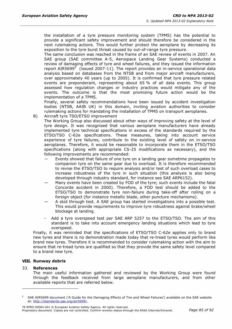
European Aviation Safety Agency CRD to NPA 2013-02
5. Updated NPA 2013-02 Explanatory Note
TE.RPRO.00064-001 © European Aviation Safety Agency. All rights reserved.
Proprietary document. Copies are not controlled. Confirm revision status through the EASA Internet/Intranet. Page 85 of 92
the installation of a tyre pressure monitoring system (TPMS) has the potential to
provide a significant safety improvement and should therefore be considered in the
next rulemaking actions. This would further protect the aeroplane by decreasing its
exposition to the tyre burst threat caused by out-of-range tyre pressure.
The same conclusion was reached in the frame of an SAE review of events in 2007. An
SAE group (SAE committee A-5, Aerospace Landing Gear Systems) conducted a
review of damaging effects of tyre and wheel failures, and they issued the information
report AIR56995 (issued 2007-11). The report provides an in-service operational data
analysis based on databases from the NTSB and from major aircraft manufacturers,
over approximately 40 years (up to 2005). It is confirmed that tyre pressure related
events are preponderant, representing about 65 % of all data events. This group
assessed how regulation changes or industry practices would mitigate any of the
events. The outcome is that the most promising future action would be the
implementation of a TPMS.
Finally, several safety recommendations have been issued by accident investigation
bodies (NTSB, AAIB UK) in this domain, inviting aviation authorities to consider
rulemaking actions for mandating the installation of TPMS on transport aeroplanes.
B) Aircraft tyre TSO/ETSO improvement
The Working Group also discussed about other ways of improving safety at the level of
tyre design. It was recognised that various aeroplane manufacturers have already
implemented tyre technical specifications in excess of the standards required by the
ETSO/TSO C-62e specifications. These measures, taking into account service
experience of tyre failures, contribute to the existing level of safety on in-service
aeroplanes. Therefore, it would be reasonable to incorporate them in the ETSO/TSO
specifications (along with appropriate CS-25 modifications as necessary), and the
following improvements are recommended:
— Events showed that failure of one tyre on a landing gear sometime propagates to
companion tyre on the same gear due to overload. It is therefore recommended
to revise the ETSO/TSO to require analysis and/or test of such overload cases to
increase robustness of the tyre in such situation (this analysis is also being
developed through industry standard, for instance see SAE ARP6152).
— Many events have been created by FOD of the tyre; such events include the fatal
Concorde accident in 2000). Therefore, a FOD test should be added to the
ETSO/TSO to demonstrate tyre non-failure during take-off after rolling on a
foreign object (for instance metallic blade, other puncture mechanisms).
— A skid through test. A SAE group has started investigations into a possible test.
This would provide requirements to improve tyre robustness against brake/wheel
blockage at landing.
- Add a tyre overspeed test per SAE ARP 5257 to the ETSO/TSO. The aim of this
standard is to take into account emergency landing situations which lead to tyre
overspeed.
Finally, it was reminded that the specifications of ETSO/TSO C-62e applies only to brand
new tyres and there is no demonstration made today that re-tread tyres would perform like
brand new tyres. Therefore it is recommended to consider rulemaking action with the aim to
ensure that re-tread tyres are qualified so that they provide the same safety level compared
to a brand new tyre.
VIII. Runway debris
33. References
The main useful information gathered and reviewed by the Working Group were found
through the feedback received from large aeroplane manufacturers, and from other
available reports that are referred below.
5 SAE AIR5699 document (‘A Guide for the Damaging Effects of Tire and Wheel Failures’) available on the SAE website
at: http://standards.sae.org/air5699/.
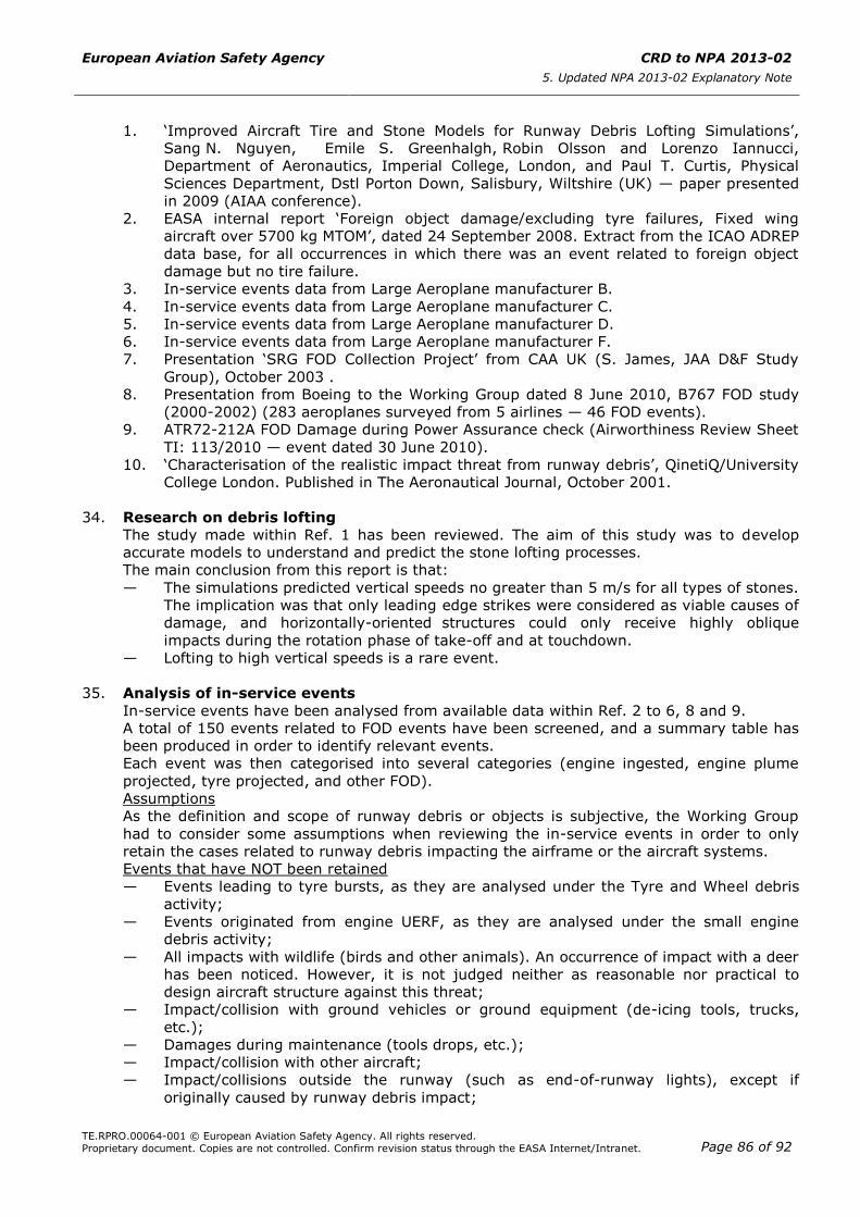
European Aviation Safety Agency CRD to NPA 2013-02
5. Updated NPA 2013-02 Explanatory Note
TE.RPRO.00064-001 © European Aviation Safety Agency. All rights reserved.
Proprietary document. Copies are not controlled. Confirm revision status through the EASA Internet/Intranet. Page 86 of 92
1. ‘Improved Aircraft Tire and Stone Models for Runway Debris Lofting Simulations’,
Sang N. Nguyen, Emile S. Greenhalgh, Robin Olsson and Lorenzo Iannucci,
Department of Aeronautics, Imperial College, London, and Paul T. Curtis, Physical
Sciences Department, Dstl Porton Down, Salisbury, Wiltshire (UK) — paper presented
in 2009 (AIAA conference).
2. EASA internal report ‘Foreign object damage/excluding tyre failures, Fixed wing
aircraft over 5700 kg MTOM’, dated 24 September 2008. Extract from the ICAO ADREP
data base, for all occurrences in which there was an event related to foreign object
damage but no tire failure.
3. In-service events data from Large Aeroplane manufacturer B.
4. In-service events data from Large Aeroplane manufacturer C.
5. In-service events data from Large Aeroplane manufacturer D.
6. In-service events data from Large Aeroplane manufacturer F.
7. Presentation ‘SRG FOD Collection Project’ from CAA UK (S. James, JAA D&F Study
Group), October 2003 .
8. Presentation from Boeing to the Working Group dated 8 June 2010, B767 FOD study
(2000-2002) (283 aeroplanes surveyed from 5 airlines — 46 FOD events).
9. ATR72-212A FOD Damage during Power Assurance check (Airworthiness Review Sheet
TI: 113/2010 — event dated 30 June 2010).
10. ‘Characterisation of the realistic impact threat from runway debris’, QinetiQ/University
College London. Published in The Aeronautical Journal, October 2001.
34. Research on debris lofting
The study made within Ref. 1 has been reviewed. The aim of this study was to develop
accurate models to understand and predict the stone lofting processes.
The main conclusion from this report is that:
— The simulations predicted vertical speeds no greater than 5 m/s for all types of stones.
The implication was that only leading edge strikes were considered as viable causes of
damage, and horizontally-oriented structures could only receive highly oblique
impacts during the rotation phase of take-off and at touchdown.
— Lofting to high vertical speeds is a rare event.
35. Analysis of in-service events
In-service events have been analysed from available data within Ref. 2 to 6, 8 and 9.
A total of 150 events related to FOD events have been screened, and a summary table has
been produced in order to identify relevant events.
Each event was then categorised into several categories (engine ingested, engine plume
projected, tyre projected, and other FOD).
Assumptions
As the definition and scope of runway debris or objects is subjective, the Working Group
had to consider some assumptions when reviewing the in-service events in order to only
retain the cases related to runway debris impacting the airframe or the aircraft systems.
Events that have NOT been retained
— Events leading to tyre bursts, as they are analysed under the Tyre and Wheel debris
activity;
— Events originated from engine UERF, as they are analysed under the small engine
debris activity;
— All impacts with wildlife (birds and other animals). An occurrence of impact with a deer
has been noticed. However, it is not judged neither as reasonable nor practical to
design aircraft structure against this threat;
— Impact/collision with ground vehicles or ground equipment (de-icing tools, trucks,
etc.);
— Damages during maintenance (tools drops, etc.);
— Impact/collision with other aircraft;
— Impact/collisions outside the runway (such as end-of-runway lights), except if
originally caused by runway debris impact;

European Aviation Safety Agency CRD to NPA 2013-02
5. Updated NPA 2013-02 Explanatory Note
TE.RPRO.00064-001 © European Aviation Safety Agency. All rights reserved.
Proprietary document. Copies are not controlled. Confirm revision status through the EASA Internet/Intranet. Page 87 of 92
— Hailstones damages in flight or on ground;
— Other ‘natural’ threats encountered in flight (e.g. volcanic ash);
— Damages due to foreign objects left on the aeroplane during maintenance;
— Parts lost from the same aeroplane, then impacting other structures/systems (not part
of this group anyway); and
— Operation on unpaved runways (outside ICAO airports).
Events that have been retained
— Debris projected by tyres;
— FOD projected by other aircraft in front;
— Debris projected by engine plume;
— Debris projected by propeller blades; and
— Other FOD from unknown origin that impacted the airframe of aircraft systems.
36. Runway FOD characterisation
The review of the retained events revealed the following characteristics:
— Most FOD events impacted and potentially created damages to tyres or engines. The
threat coming from subsequent tyre and engine debris are covered in dedicated
activities and models. Therefore, they are not retained here (not part of Table 2
below). In the end, 40 events out of 150 have been retained as relevant for Runway
Debris analysis. See table 1 below.
— FOD did not cause any injuries.
— Most of the events lead to minor aircraft damages.
— FOD caused neither fuel leaks nor fires.
— There is very limited data showing ejected foreign objects from tyre pinch (only
two events have been identified as potentially created by such effect: a first
event created small damages to lower wing trailing edge secondary structure
panels, a second event created a 0.145 inch dent depth in fuselage lower skin in
line with Nose Landing Gear).
— There were significant damages from engine plume ejected debris (17 events
out of 40).
— Few occurrences of windshield cracking were caused by FOD. These may have
been caused by plume projected debris from another aeroplane (three events).
— In one event, fuselage damage was caused by stones projected by propeller
blade.
— The other occurrences covered: foreign objects damaging a Pitot probe,
telephone wire, tow strap stuck in NLG, damage to lamps and covers.
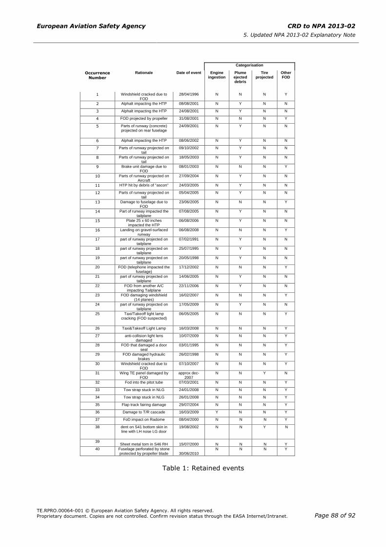
European Aviation Safety Agency CRD to NPA 2013-02
5. Updated NPA 2013-02 Explanatory Note
TE.RPRO.00064-001 © European Aviation Safety Agency. All rights reserved.
Proprietary document. Copies are not controlled. Confirm revision status through the EASA Internet/Intranet. Page 88 of 92
Table 1: Retained events
Categorisation
Occurrence
Number
Rationale Date of event Engine ingestion
Plume ejected debris
Tire projected
Other FOD
1 Windshield cracked due to FOD
28/04/1996 N N N Y
2 Alphalt impacting the HTP 08/08/2001 N Y N N
3 Alphalt impacting the HTP 24/08/2001 N Y N N
4 FOD projected by propeller 31/08/2001 N N N Y
5
Parts of runway (concrete) projected on rear fuselage
24/09/2001 N Y N N
6 Alphalt impacting the HTP 08/06/2002 N Y N N
7 Parts of runway projected on tail
09/10/2002 N Y N N
8 Parts of runway projected on tail
18/05/2003 N Y N N
9 Brake unit damage due to FOD
08/01/2003 N N N Y
10 Parts of runway projected on Aircraft
27/09/2004 N Y N N
11 HTP hit by debris of "ascon'' 24/03/2005 N Y N N
12 Parts of runway projected on tail
05/04/2005 N Y N N
13 Damage to fuselage due to FOD
23/06/2005 N N N Y
14 Part of runway impacted the tailplane
07/08/2005 N Y N N
15 Plate 25 x 60 inches impacted the HTP
06/08/2006 N Y N N
16 Landing on gravel-surfaced runway
06/08/2008 N N N Y
17 part of runway projected on tailplane
07/02/1991 N Y N N
18 part of runway projected on tailplane
25/07/1995 N Y N N
19 part of runway projected on tailplane
20/05/1998 N Y N N
20 FOD (telephone impacted the fuselage)
17/12/2002 N N N Y
21 part of runway projected on tailplane
14/06/2005 N Y N N
22 FOD from another A/C impacting Tailplane
22/11/2006 N Y N N
23 FOD damaging windshield (14 planes)
16/02/2007 N N N Y
24 part of runway projected on tailplane
17/05/2009 N Y N N
25 Taxi/Takeoff light lamp cracking (FOD suspected)
06/05/2005 N N N Y
26 Taxi&Takeoff Light Lamp 16/03/2008 N N N Y
27 anti-collision light lens damaged
10/07/2009 N N N Y
28 FOD that damaged a door seal
03/01/1995 N N N Y
29 FOD damaged hydraulic brakes
26/02/1998 N N N Y
30 Windshield cracked due to FOD
07/10/2007 N N N Y
31 Wing TE panel damaged by FOD
approx dec-2007
N N Y N
32 Fod into the pitot tube 07/03/2001 N N N Y
33 Tow strap stuck in NLG 24/01/2008 N N N Y
34 Tow strap stuck in NLG 26/01/2008 N N N Y
35 Flap track fairing damage 29/07/2004 N N N Y
36 Damage to T/R cascade 16/03/2009 Y N N Y
37 FoD impact on Radome 08/04/2000 N N N Y
38 dent on S41 bottom skin in line with LH nose LG door
19/08/2002 N N Y N
39 Sheet metal torn in S46 RH 15/07/2000 N N N Y
40 Fuselage perforated by stone protected by propeller blade 30/06/2010
N N N Y

European Aviation Safety Agency CRD to NPA 2013-02
5. Updated NPA 2013-02 Explanatory Note
TE.RPRO.00064-001 © European Aviation Safety Agency. All rights reserved.
Proprietary document. Copies are not controlled. Confirm revision status through the EASA Internet/Intranet. Page 89 of 92
37. Discussion
Foreign objects ejected by the tyres: It appears that runway foreign objects ejected from
tyres are very rare events. The review of in-service experience indeed confirms the
conclusion from Ref. 1 research study. Only two potential occurrences have been identified
and the corresponding reports provide very little details. The consequence on the airframe
or aircraft systems is judged to be minor. Based on this, it is proposed not to characterise
this threat.
Foreign objects impacting Pitot probes: These events are considered minor as only one
probe was lost.
Foreign objects impacting the aircraft (excluding plume projected debris): Only minor
damage to the airframe or aircraft systems has been identified.
The design of the aeroplane based on existing rules (e.g. CS/FAR 25.571 Damage-tolerance
and fatigue evaluation of structure, 25.631 Bird strike damage, 25.1309 Equipment,
systems and installations) appears to provide an adequate level of protection against impact
from this type of runway debris.
Additionally separation of aircraft during taxi, take-off and landing phases also helps
preventing foreign object projections from other aircraft in front.
Engine plume projected debris, or propeller blade projected debris:
Several events have created significant damage to the aeroplane aft fuselage or horizontal
tail plane, although no damage to essential systems has been reported.
Most of these events have not a clear reporting of the debris size.
The most severe damage found is the event faced by Airbus A320 F-GFKI
on 7 February 1997 when taking off from Nîmes-Garons airport, France (see BEA report f-
ki910207). During this event very large asphalt parts of the runway were detached and
projected by the engine plume effect and impacted the horizontal tail plane (see Table 2
below).
Type Weight
(kg) Shape/Size
Speed at impact Vx
(m/s)
Speed at impact Vz
(m/s)
Projection distance
Speed of debris
impacting the HTP
A 50
Flat
80 cm × 70 cm
Thickness 7 cm
14.6 12.5 11.2 10.2
8.3 11.1 13.5 15.6
25 m 17 m/s
B 10
Flat
33 cm × 33 cm
Thickness 7 cm
14.6 12.5 11.2 10.2
8.3 11.1 13.5 15.6
50 m 27 m/s
C 1
Flat
10 cm × 11 cm
Thickness 7 cm
14.8 12.6 11.2 10.3
8.5 11.2 13.6 15.7
100 m 43 m/s
D 0.10 Spherical
Diameter 5 cm
15.0 12.7 11.3 10.4 9.4
8.7 11.8 14.0 16.2 17.4
200 m 65 m/s
Table 2: Debris ballistic analysis from BEA report f-ki910207
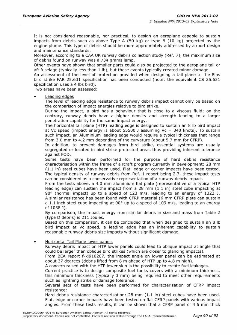
European Aviation Safety Agency CRD to NPA 2013-02
5. Updated NPA 2013-02 Explanatory Note
TE.RPRO.00064-001 © European Aviation Safety Agency. All rights reserved.
Proprietary document. Copies are not controlled. Confirm revision status through the EASA Internet/Intranet. Page 90 of 92
It is not considered reasonable, nor practical, to design an aeroplane capable to sustain
impacts from debris such as above Type A (50 kg) or type B (10 kg) projected by the
engine plume. This type of debris should be more appropriately addressed by airport design
and maintenance standards.
Moreover, according to a CAA UK runway debris collection study (Ref. 7), the maximum size
of debris found on runway was a 734 grams lamp.
Other events have shown that smaller parts could also be projected to the aeroplane tail or
aft fuselage (typically less than 1 lb), but these events typically created minor damage.
An assessment of the level of protection provided when designing a tail plane to the 8lbs
bird strike FAR 25.631 specification has been conducted (note: the equivalent CS 25.631
specification uses a 4 lbs bird).
Two areas have been assessed:
• Leading edges
The level of leading edge resistance to runway debris impact cannot only be based on
the comparison of impact energies relative to bird strike.
During the impact, a bird has a behaviour that is close to a viscous fluid; on the
contrary, runway debris have a higher density and strength leading to a larger
penetration capability for the same impact energy.
The horizontal tail plane (HTP) leading edge is designed to sustain an 8 lb bird impact
at Vc speed (impact energy is about 55500 J assuming Vc = 340 knots). To sustain
such impact, an Aluminium leading edge would require a typical thickness that range
from 3.0 mm to 4.2 mm depending of the curvature (about 5.7 mm for CFRP).
In addition, to prevent damages from bird strike, essential systems are usually
segregated or located in bird strike protected areas thus providing inherent tolerance
against FOD.
Some tests have been performed for the purpose of hard debris resistance
characterisation within the frame of aircraft program currently in development: 28 mm
(1.1 in) steel cubes have been used. Flat, edge or corner impacts have been tested.
The typical density of runway debris from Ref. 1 report being 2.7, these impact tests
can be considered as a conservative representation of a runway debris impact.
From the tests above, a 4.0 mm aluminium flat plate (representative of a typical HTP
leading edge) can sustain the impact from a 28 mm (1.1 in) steel cube impacting at
90° (normal impact) up to a speed of 123 m/s, leading to an energy of 1322 J.
A similar resistance has been found with CFRP material (6 mm CFRP plate can sustain
a 1.1 inch steel cube impacting at 90° up to a speed of 109 m/s, leading to an energy
of 1038 J).
By comparison, the impact energy from similar debris in size and mass from Table 2
(type D debris) is 211 Joules.
Based on this comparison, it can be concluded that when designed to sustain an 8 lb
bird impact at Vc speed, a leading edge has an inherent capability to sustain
reasonable runway debris size impacts without significant damage.
• Horizontal Tail Plane lower panels
Runway debris impact on HTP lower panels could lead to oblique impact at angle that
could be larger than oblique bird strikes (which are closer to glancing impacts).
From BEA report f-ki910207, the impact angle on lower panel can be estimated at
about 37 degrees (debris lifted from 8 m ahead of HTP up to 4.8 m high).
A concern raised with the HTP lower skin is the possibility to create fuel leakages.
Current practice is to design composite fuel tanks covers with a minimum thickness,
this minimum thickness (typically 3 mm) being required to meet other requirements
such as lightning strike or damage tolerance.
Several sets of tests have been performed for characterisation of CFRP impact
resistance:
Hard debris resistance characterisation: 28 mm (1.1 in) steel cubes have been used.
Flat, edge or corner impacts have been tested on flat CFRP panels with various impact
angles. From these tests results, it can be shown that a CFRP panel of 4.6 mm thick

European Aviation Safety Agency CRD to NPA 2013-02
5. Updated NPA 2013-02 Explanatory Note
TE.RPRO.00064-001 © European Aviation Safety Agency. All rights reserved.
Proprietary document. Copies are not controlled. Confirm revision status through the EASA Internet/Intranet. Page 91 of 92
can resist to 28 mm (1.1 in) steel cubes at 182 m/s impact for 11 degrees angle
(2895 J)
When extrapolating these results to the estimated obliquity angle from report
f-ki910207 (37 degrees), an energy of about 600 J would be required to reach
perforation of a typical HTP lower panel (CFRP 3 mm thick).
Based on this comparison, it can be shown that typical HTP lower panels should be
capable to sustain reasonable runway debris sizes without perforation, when taking
into account a typical impact obliquity angle.
38. Damage tolerance considerations
Although most of the impacts from runway debris create visible damage indications such as
dents, scratches, holes or marks, the theoretical possibility of small/soft debris that could
create undetected damage has been discussed by the Working Group.
For metallic structures, hidden damage resulting from a runway debris impact may lead to
crack initiation and possibly propagation. Thanks to design compliant with CS/FAR 25.571,
these cracks will be detected within the normal maintenance activity before they could
become critical.
For composite structures, general damage tolerance approach includes the assessment of
the effects of impact damage. Guidance material is available on these matters.
According to EASA AMC 20-29, harmonised with FAA AC20-107B (Composite Aircraft
Structure), paragraph 7.f: ‘It should be shown that impact damage that can be likely
expected from manufacturing and service, but not more than the established threshold of
detectability for the selected inspection procedure, will not reduce the structural strength
below ultimate load capability.’
The CMH-17 (Composite Material Handbook6) proposes to represent runway debris by
Visible Impact Damages (VIDs). These VIDs could be created using a 1.0 inch hemispherical
impactor and energies up to 136 J or up to energy required to create a visible dent (2.5 mm
deep).
Therefore, it was concluded that actual available Damage Tolerance rules or guidance
material, applicable to either metallic or composite structures, are adequately addressing
potential impacts from runway debris.
39. Runway debris — conclusion and recommendation
Based on the discussions above, summarised below, it is not recommended to characterise
the runway debris threat.
Indeed, tyre projected FOD are very rare events and their impact on the airframe or aircraft
systems have been minor. The aeroplane is protected against tyre, wheel and engine debris
which indirectly provides robustness and protection against runway debris impacts.
Propulsion engine plume projected debris are mainly impacting the horizontal tail plane
leading edge. The level of protection provided by typical tail plane leading edge sizing, in
particular thanks to the 8 lb bird strike requirement from FAR 25.631 is found to be
adequate to cover most of events involving reasonable runway debris sizes (typically up to
1 lb).
Propulsion engine plume projected debris could also impact the tail plane lower skin. It has
been shown that taking into account the oblique impact angle, a typical lower skin thickness
would be capable to sustain reasonable runway debris sizes without perforation.
Other FOD impacts have minor effects on the structure and/or systems.
Damage Tolerance rules and guidance material applicable to either metallic or composite
structures are adequately covering potential impacts from runway debris. This coverage is
6 The Composite Materials Handbook (CMH) provides information and guidance necessary to design and fabricate end
items from composite materials. Its primary purpose is the standardisation of engineering data development methodologies related to testing, data reduction, and data reporting of property data for current and emerging composite materials. In support of this objective, the handbook includes composite materials properties that meet specific data requirements. The CMH is a volunteer organisation consisting of participants from industry, government, and academia. More information available at: http://www.cmh17.org.
European Aviation Safety Agency CRD to NPA 2013-02
5. Updated NPA 2013-02 Explanatory Note
TE.RPRO.00064-001 © European Aviation Safety Agency. All rights reserved.
Proprietary document. Copies are not controlled. Confirm revision status through the EASA Internet/Intranet. Page 92 of 92
provided by CS 25.571 and its AMC and for composite structures there is the additional
guidance of AMC 20-29/AC 20-107B explicitly identifying runway debris threat which is
addressed into more details in CMH-17.
It is recommended to improve airports FOD prevention to complement the current
dispositions of ICAO Annex 14, so as to ensure that large debris on the runway will be
detected before they create severe damage to the aircraft.