Embed Size (px)
Citation preview
BRITISH STANDARD BS EN 1993-1-8:2005
Eurocode 3: Design of
steel structures —
Part 1-8: Design of joints
The European Standard EN 1993-1-8:2005 has the status of a British Standard
ICS 91.010.30
���������������� ������������������������������� �������������
Incorporating Corrigenda Nos. 1 and 2
Lice
nsed
Cop
y: M
r. U
nive
rsiti
Tek
nolo
gi M
alay
sia
Use
r, U
nive
rsiti
Tek
nolo
gi M
alay
sia,
21/
02/2
008
04:0
9, U
ncon
trol
led
Cop
y, (
c) B
SI

BS EN 1993-1-8:2005
This British Standard, was published under the authority of the Standards Policy and Strategy Committee on 17 May 2005
ISBN 0 580 46081 9
National foreword
This British Standard is the official English language version of EN 1993-1-8:2005, including Corrigendum December 2005. It supersedes DD ENV 1993-1-1:1992, which is withdrawn.
The structural Eurocodes are divided into packages by grouping Eurocodes for each of the main materials, concrete, steel, composite concrete and steel, timber, masonry and aluminium, this is to enable a common date of withdrawal (DOW) for all the relevant parts that are needed for a particular design. The conflicting national standards will be withdrawn at the end of the coexistence period, after all the EN Eurocodes of a package are available.Following publication of the EN, there is a period allowed for national calibration during which the national annex is issued, followed by a coexistence period of a maximum 3 years. During the coexistence period Member States are encouraged to adapt their national provisions. Conflicting national standards will be withdrawn by March 2010 at the latest.BS EN 1993-1-8 will partially supersede BS 449-2, BS 4604-1, BS 4604-2, BS 5400-3 and BS 5950-1, which will be withdrawn by March 2010.The UK participation in its preparation was entrusted by Technical Committee B/525, Building and civil engineering structures, to Subcommittee B/525/31, Structural use of steel, which has the responsibility to:
A list of organizations represented on this subcommittee can be obtained on request to its secretary.Where a normative part of this EN allows for a choice to be made at the national level, the range and possible choice will be given in the normative text, and a note will qualify it as a Nationally Determined Parameter (NDP). NDPs can be a specific value for a factor, a specific level or class, a particular method or a particular application rule if several are proposed in the EN.To enable EN 1993-1-8 to be used in the UK, the NDPs will be published in a National Annex, which will be made available by BSI in due course, after public consultation has taken place.
— aid enquirers to understand the text;
— present to the responsible international/European committee any enquiries on the interpretation, or proposals for change, and keep UK interests informed;
— monitor related international and European developments and promulgate them in the UK.
© BSI 2006
Amendments issued since publication
Amd. No. Date Comments
16291 Corrigendum No. 1
June 2006 See note in National foreword
16571 Corrigendum No. 2
September 2006supersession details
NOTE Corrigendum No. 1 implements a CEN Corrigendum which adds “P” after the clause number and replaces the word “should” with “shall” in the following clauses and subclauses: 2.2(1) and (3), 2.3(1), 2.5(1), 4.1(2), 6.4.1(1), 7.2.1(1) and (2), 7.3.1(1) and 7.4.2(1).
Revision of national foreword and
Lice
nsed
Cop
y: M
r. U
nive
rsiti
Tek
nolo
gi M
alay
sia
Use
r, U
nive
rsiti
Tek
nolo
gi M
alay
sia,
21/
02/2
008
04:0
9, U
ncon
trol
led
Cop
y, (
c) B
SI
BS EN 1993-1-8:2005
i
This publication does not purport to include all the necessary provisions of a contract. Users are responsible for its correct application. Compliance with a British Standard does not of itself confer immunity from legal obligations.
Summary of pagesThis document comprises a front cover, an inside front cover, page i, a blank page, the EN title page, pages 2 to 133 and a back cover.The BSI copyright notice displayed in this document indicates when the document was last issued.
Lice
nsed
Cop
y: M
r. U
nive
rsiti
Tek
nolo
gi M
alay
sia
Use
r, U
nive
rsiti
Tek
nolo
gi M
alay
sia,
21/
02/2
008
04:0
9, U
ncon
trol
led
Cop
y, (
c) B
SI

blank
Lice
nsed
Cop
y: M
r. U
nive
rsiti
Tek
nolo
gi M
alay
sia
Use
r, U
nive
rsiti
Tek
nolo
gi M
alay
sia,
21/
02/2
008
04:0
9, U
ncon
trol
led
Cop
y, (
c) B
SI
EUROPEAN STANDARD
NORME EUROPÉENNE
EUROPÄISCHE NORM
EN 1993-1-8
May 2005
ICS 91.010.30 Supersedes ENV 1993-1-1:1992
English version
Eurocode 3: Design of steel structures - Part 1-8: Design of joints
Eurocode 3: Calcul des structures en acier - Partie 1-8: Calcul des assemblages
Eurocode 3: Bemessung und Konstruktion von Stahlbauten - Teil 1-8: Bemessung von Anschlüssen
This European Standard was approved by CEN on 16 April 2004.
CEN members are bound to comply with the CEN/CENELEC Internal Regulations which stipulate the conditions for giving this European Standard the status of a national standard without any alteration. Up-to-date lists and bibliographical references concerning such national standards may be obtained on application to the Central Secretariat or to any CEN member.
This European Standard exists in three official versions (English, French, German). A version in any other language made by translation under the responsibility of a CEN member into its own language and notified to the Central Secretariat has the same status as the official versions.
CEN members are the national standards bodies of Austria, Belgium, Cyprus, Czech Republic, Denmark, Estonia, Finland, France, Germany, Greece, Hungary, Iceland, Ireland, Italy, Latvia, Lithuania, Luxembourg, Malta, Netherlands, Norway, Poland, Portugal, Slovakia, Slovenia, Spain, Sweden, Switzerland and United Kingdom.
EUROPEAN COMMITTEE FOR STANDARDIZATION C O M I T É E U R O P É E N D E N O R M A L I S A T I O N E U R O P Ä I S C H E S K O M I T E E F Ü R N O R M U N G
Management Centre: rue de Stassart, 36 B-1050 Brussels
© 2005 CEN All rights of exploitation in any form and by any means reserved worldwide for CEN national Members.
Ref. No. EN 1993-1-8:2005: E
Incorporating CorrigendumDecember 2005
Lice
nsed
Cop
y: M
r. U
nive
rsiti
Tek
nolo
gi M
alay
sia
Use
r, U
nive
rsiti
Tek
nolo
gi M
alay
sia,
21/
02/2
008
04:0
9, U
ncon
trol
led
Cop
y, (
c) B
SI
EN 1993-1-8 : 2005 (E)
2
Contents Page
1 Introduction ............................................................................................................................................. 8
1.1 Scope ................................................................................................................................................. 81.2 Normative references......................................................................................................................... 81.3 Distinction between Principles and Application Rules ....................................................................101.4 Terms and definitions .......................................................................................................................101.5 Symbols ............................................................................................................................................13
2 Basis of design .........................................................................................................................................18
2.1 Assumptions .....................................................................................................................................182.2 General requirements........................................................................................................................182.3 Applied forces and moments ............................................................................................................182.4 Resistance of joints...........................................................................................................................182.5 Design assumptions ..........................................................................................................................192.6 Joints loaded in shear subject to impact, vibration and/or load reversal ..........................................192.7 Eccentricity at intersections..............................................................................................................19
3 Connections made with bolts, rivets or pins.........................................................................................20
3.1 Bolts, nuts and washers ....................................................................................................................203.1.1 General .....................................................................................................................................203.1.2 Preloaded bolts .........................................................................................................................20
3.2 Rivets................................................................................................................................................203.3 Anchor bolts .....................................................................................................................................213.4 Categories of bolted connections......................................................................................................21
3.4.1 Shear connections .....................................................................................................................213.4.2 Tension connections .................................................................................................................21
3.5 Positioning of holes for bolts and rivets ...........................................................................................233.6 Design resistance of individual fasteners .........................................................................................24
3.6.1 Bolts and rivets .........................................................................................................................243.6.2 Injection bolts ...........................................................................................................................28
3.7 Group of fasteners ............................................................................................................................293.8 Long joints........................................................................................................................................293.9 Slip-resistant connections using 8.8 or 10.9 bolts ............................................................................30
3.9.1 Design Slip resistance...............................................................................................................303.9.2 Combined tension and shear.....................................................................................................313.9.3 Hybrid connections...................................................................................................................31
3.10 Deductions for fastener holes ...........................................................................................................313.10.1 General .....................................................................................................................................313.10.2 Design for block tearing ...........................................................................................................323.10.3 Angles connected by one leg and other unsymmetrically connected members in tension .......333.10.4 Lug angles ................................................................................................................................34
3.11 Prying forces.....................................................................................................................................343.12 Distribution of forces between fasteners at the ultimate limit state..................................................343.13 Connections made with pins.............................................................................................................35
3.13.1 General .....................................................................................................................................353.13.2 Design of pins...........................................................................................................................35
4 Welded connections ................................................................................................................................38
4.1 General .............................................................................................................................................384.2 Welding consumables.......................................................................................................................384.3 Geometry and dimensions ................................................................................................................38
4.3.1 Type of weld.............................................................................................................................384.3.2 Fillet welds ...............................................................................................................................384.3.3 Fillet welds all round ................................................................................................................404.3.4 Butt welds.................................................................................................................................404.3.5 Plug welds ................................................................................................................................41
Lice
nsed
Cop
y: M
r. U
nive
rsiti
Tek
nolo
gi M
alay
sia
Use
r, U
nive
rsiti
Tek
nolo
gi M
alay
sia,
21/
02/2
008
04:0
9, U
ncon
trol
led
Cop
y, (
c) B
SI
EN 1993-1-8 : 2005 (E)
3
4.3.6 Flare groove welds....................................................................................................................414.4 Welds with packings.........................................................................................................................414.5 Design resistance of a fillet weld......................................................................................................42
4.5.1 Length of welds ........................................................................................................................424.5.2 Effective throat thickness .........................................................................................................424.5.3 Design Resistance of fillet welds..............................................................................................42
4.6 Design resistance of fillet welds all round........................................................................................444.7 Design resistance of butt welds ........................................................................................................45
4.7.1 Full penetration butt welds .......................................................................................................454.7.2 Partial penetration butt welds ...................................................................................................454.7.3 T-butt joints ..............................................................................................................................45
4.8 Design resistance of plug welds .......................................................................................................454.9 Distribution of forces........................................................................................................................464.10 Connections to unstiffened flanges...................................................................................................464.11 Long joints........................................................................................................................................484.12 Eccentrically loaded single fillet or single-sided partial penetration butt welds ..............................484.13 Angles connected by one leg ............................................................................................................484.14 Welding in cold-formed zones .........................................................................................................49
5 Analysis, classification and modelling ..................................................................................................50
5.1 Global analysis .................................................................................................................................505.1.1 General .....................................................................................................................................505.1.2 Elastic global analysis ..............................................................................................................505.1.3 Rigid-plastic global analysis.....................................................................................................515.1.4 Elastic- plastic global analysis..................................................................................................515.1.5 Global analysis of lattice girders ..............................................................................................52
5.2 Classification of joints ......................................................................................................................545.2.1 General .....................................................................................................................................545.2.2 Classification by stiffness .........................................................................................................545.2.3 Classification by strength .........................................................................................................55
5.3 Modelling of beam-to-column joints ................................................................................................56
6 Structural joints connecting H or I sections.........................................................................................60
6.1 General .............................................................................................................................................606.1.1 Basis .........................................................................................................................................606.1.2 Structural properties .................................................................................................................606.1.3 Basic components of a joint......................................................................................................61
6.2 Design Resistance.............................................................................................................................656.2.1 Internal forces ...........................................................................................................................656.2.2 Shear forces ..............................................................................................................................656.2.3 Bending moments .....................................................................................................................666.2.4 Equivalent T-stub in tension.....................................................................................................676.2.5 Equivalent T-stub in compression ............................................................................................706.2.6 Design Resistance of basic components ...................................................................................716.2.7 Design moment resistance of beam-to-column joints and splices ............................................846.2.8 Design resistance of column bases with base plates.................................................................89
6.3 Rotational stiffness ...........................................................................................................................926.3.1 Basic model ..............................................................................................................................926.3.2 Stiffness coefficients for basic joint components .....................................................................946.3.3 End-plate joints with two or more bolt-rows in tension ...........................................................976.3.4 Column bases............................................................................................................................98
6.4 Rotation capacity ..............................................................................................................................996.4.1 General .....................................................................................................................................996.4.2 Bolted joints............................................................................................................................1006.4.3 Welded Joints .........................................................................................................................100
7 Hollow section joints.............................................................................................................................101
7.1 General ...........................................................................................................................................101
Lice
nsed
Cop
y: M
r. U
nive
rsiti
Tek
nolo
gi M
alay
sia
Use
r, U
nive
rsiti
Tek
nolo
gi M
alay
sia,
21/
02/2
008
04:0
9, U
ncon
trol
led
Cop
y, (
c) B
SI
EN 1993-1-8 : 2005 (E)
4
7.1.1 Scope ......................................................................................................................................1017.1.2 Field of application.................................................................................................................101
7.2 Design.............................................................................................................................................1037.2.1 General ...................................................................................................................................1037.2.2 Failure modes for hollow section joints..................................................................................103
7.3 Welds..............................................................................................................................................1077.3.1 Design resistance ....................................................................................................................107
7.4 Welded joints between CHS members ...........................................................................................1087.4.1 General ...................................................................................................................................1087.4.2 Uniplanar joints ......................................................................................................................1087.4.3 Multiplanar joints ...................................................................................................................115
7.5 Welded joints between CHS or RHS brace members and RHS chord members ...........................1167.5.1 General ...................................................................................................................................1167.5.2 Uniplanar joints ......................................................................................................................1177.5.3 Multiplanar joints ...................................................................................................................128
7.6 Welded joints between CHS or RHS brace members and I or H section chords ...........................1297.7 Welded joints between CHS or RHS brace members and channel section chord members ..........132
Lice
nsed
Cop
y: M
r. U
nive
rsiti
Tek
nolo
gi M
alay
sia
Use
r, U
nive
rsiti
Tek
nolo
gi M
alay
sia,
21/
02/2
008
04:0
9, U
ncon
trol
led
Cop
y, (
c) B
SI

EN 1993-1-8 : 2005 (E)
5
Foreword
This European Standard EN 1993, Eurocode 3: Design of steel structures, has been prepared by Technical Committee CEN/TC250 « Structural Eurocodes », the Secretariat of which is held by BSI. CEN/TC250 is responsible for all Structural Eurocodes.
This European Standard shall be given the status of a National Standard, either by publication of an identical text or by endorsement, at the latest by November 2005, and conflicting National Standards shall be withdrawnat latest by March 2010.
This Eurocode supersedes ENV 1993-1-1.
According to the CEN-CENELEC Internal Regulations, the National Standard Organizations of the following countries are bound to implement these European Standard: Austria, Belgium, Cyprus, Czech Republic, Denmark, Estonia, Finland, France, Germany, Greece, Hungary, Iceland, Ireland, Italy, Latvia, Lithuania, Luxembourg, Malta, Netherlands, Norway, Poland, Portugal, Slovakia, Slovenia, Spain, Sweden, Switzerland and United Kingdom.
Background to the Eurocode programme
In 1975, the Commission of the European Community decided on an action programme in the field of construction, based on article 95 of the Treaty. The objective of the programme was the elimination of technical obstacles to trade and the harmonization of technical specifications.
Within this action programme, the Commission took the initiative to establish a set of harmonized technical rules for the design of construction works which, in a first stage, would serve as an alternative to the national rules in force in the Member States and, ultimately, would replace them.
For fifteen years, the Commission, with the help of a Steering Committee with Representatives of Member States, conducted the development of the Eurocodes programme, which led to the first generation of European codes in the 1980s.
In 1989, the Commission and the Member States of the EU and EFTA decided, on the basis of an agreement1
between the Commission and CEN, to transfer the preparation and the publication of the Eurocodes to CEN through a series of Mandates, in order to provide them with a future status of European Standard (EN). This links de facto the Eurocodes with the provisions of all the Council’s Directives and/or Commission’s Decisions dealing with European standards (e.g. the Council Directive 89/106/EEC on construction products - CPD - and Council Directives 93/37/EEC, 92/50/EEC and 89/440/EEC on public works and services and equivalent EFTA Directives initiated in pursuit of setting up the internal market).
The Structural Eurocode programme comprises the following standards generally consisting of a number of Parts:
EN 1990 Eurocode 0: Basis of Structural Design EN 1991 Eurocode 1: Actions on structures EN 1992 Eurocode 2: Design of concrete structures EN 1993 Eurocode 3: Design of steel structures EN 1994 Eurocode 4: Design of composite steel and concrete structures EN 1995 Eurocode 5: Design of timber structures EN 1996 Eurocode 6: Design of masonry structures EN 1997 Eurocode 7: Geotechnical design EN 1998 Eurocode 8: Design of structures for earthquake resistance EN 1999 Eurocode 9: Design of aluminium structures
1
Agreement between the Commission of the European Communities and the European Committee for Standardisation (CEN) concerning the work on EUROCODES for the design of building and civil engineering works (BC/CEN/03/89).
Lice
nsed
Cop
y: M
r. U
nive
rsiti
Tek
nolo
gi M
alay
sia
Use
r, U
nive
rsiti
Tek
nolo
gi M
alay
sia,
21/
02/2
008
04:0
9, U
ncon
trol
led
Cop
y, (
c) B
SI

EN 1993-1-8 : 2005 (E)
6
Eurocode standards recognize the responsibility of regulatory authorities in each Member State and have safeguarded their right to determine values related to regulatory safety matters at national level where these continue to vary from State to State.
Status and field of application of eurocodes
The Member States of the EU and EFTA recognize that Eurocodes serve as reference documents for the following purposes :
– as a means to prove compliance of building and civil engineering works with the essential requirements of Council Directive 89/106/EEC, particularly Essential Requirement N°1 – Mechanical resistance and stability – and Essential Requirement N°2 – Safety in case of fire;
– as a basis for specifying contracts for construction works and related engineering services;
– as a framework for drawing up harmonized technical specifications for construction products (ENs and ETAs)
The Eurocodes, as far as they concern the construction works themselves, have a direct relationship with the Interpretative Documents2 referred to in Article 12 of the CPD, although they are of a different nature from harmonized product standards3. Therefore, technical aspects arising from the Eurocodes work need to be adequately considered by CEN Technical Committees and/or EOTA Working Groups working on product standards with a view to achieving full compatibility of these technical specifications with the Eurocodes.
The Eurocode standards provide common structural design rules for everyday use for the design of whole structures and component products of both a traditional and an innovative nature. Unusual forms of construction or design conditions are not specifically covered and additional expert consideration will be required by the designer in such cases.
National Standards implementing Eurocodes
The National Standards implementing Eurocodes will comprise the full text of the Eurocode (including any annexes), as published by CEN, which may be preceded by a National title page and National foreword, and may be followed by a National annex.
The National annex may only contain information on those parameters which are left open in the Eurocode for national choice, known as Nationally Determined Parameters, to be used for the design of buildings and civil engineering works to be constructed in the country concerned, i.e. : – values and/or classes where alternatives are given in the Eurocode, – values to be used where a symbol only is given in the Eurocode, – country specific data (geographical, climatic, etc.), e.g. snow map, – the procedure to be used where alternative procedures are given in the Eurocode. It may contain – decisions on the application of informative annexes, – references to non-contradictory complementary information to assist the user to apply the Eurocode.
Links between Eurocodes and harmonized technical specifications (ENs and ETAs) for
products
2
According to Art. 3.3 of the CPD, the essential requirements (ERs) shall be given concrete form in interpretative documents for the creation of the necessary links between the essential requirements and the mandates for harmonized ENs and ETAGs/ETAs.
3 According to Art. 12 of the CPD the interpretative documents shall :
a) give concrete form to the essential requirements by harmonizing the terminology and the technical bases and indicating classes or levels for each requirement where necessary ;
b) indicate methods of correlating these classes or levels of requirement with the technical specifications, e.g. methods of calculation and of proof, technical rules for project design, etc. ;
c) serve as a reference for the establishment of harmonized standards and guidelines for European technical approvals.
The Eurocodes, de facto, play a similar role in the field of the ER 1 and a part of ER 2.
Lice
nsed
Cop
y: M
r. U
nive
rsiti
Tek
nolo
gi M
alay
sia
Use
r, U
nive
rsiti
Tek
nolo
gi M
alay
sia,
21/
02/2
008
04:0
9, U
ncon
trol
led
Cop
y, (
c) B
SI
EN 1993-1-8 : 2005 (E)
7
There is a need for consistency between the harmonized technical specifications for construction products and the technical rules for works4. Furthermore, all the information accompanying the CE Marking of the construction products which refer to Eurocodes should clearly mention which Nationally Determined Parameters have been taken into account.
National annex for EN 1993-1-8
This standard gives alternative procedures, values and recommendations with notes indicating where national choices may have to be made. The National Standard implementing EN 1993-1-8 should have a National Annex containing all Nationally Determined Parameters for the design of steel structures to be constructed in the relevant country.
National choice is allowed in EN 1993-1-8 through:
– 2.2(2)
– 1.2.6 (Group 6: Rivets)
– 3.1.1(3)
– 3.4.2(1)
– 5.2.1(2)
– 6.2.7.2(9)
4
see Art.3.3 and Art.12 of the CPD, as well as clauses 4.2, 4.3.1, 4.3.2 and 5.2 of ID 1.
Lice
nsed
Cop
y: M
r. U
nive
rsiti
Tek
nolo
gi M
alay
sia
Use
r, U
nive
rsiti
Tek
nolo
gi M
alay
sia,
21/
02/2
008
04:0
9, U
ncon
trol
led
Cop
y, (
c) B
SI
EN 1993-1-8 : 2005 (E)
8
1 Introduction
1.1 Scope
(1) This part of EN 1993 gives design methods for the design of joints subject to predominantly static loading using steel grades S235, S275, S355 and S460.
1.2 Normative references
This European Standard incorporates by dated or undated reference, provisions from other publications. These normative references are cited at the appropriate places in the text and the publications are listed hereafter. For dated references, subsequent amendments to or revisions of any of these publications apply to this European Standard, only when incorporated in it by amendment or revision. For undated references the latest edition of the publication referred to applies (including amendments).
1.2.1 Reference Standards, Group 1: Weldable structural steels
EN 10025-1:2004 Hot rolled products of structural steels. General technical delivery conditions
EN 10025-2:2004 Hot rolled products of structural steels. Technical delivery conditions for non-alloy structural steels
EN 10025-3:2004 Hot rolled products of structural steels. Technical delivery conditions for normalized/normalized rolled weldable fine grain structural steels
EN 10025-4:2004 Hot rolled products of structural steels. Technical delivery conditions for thermomechanical rolled weldable fine grain structural steels
EN 10025-5:2004 Hot rolled products of structural steels. Technical delivery conditions for structural steels with improved atmospheric corrosion resistance
EN 10025-6:2004 Hot rolled products of structural steels. Technical delivery conditions for flat products of high yield strength structural steels in quenched and tempered condition
1.2.2 Reference Standards, Group 2: Tolerances, dimensions and technical delivery conditions
EN 10029:1991 Hot rolled steel plates 3 mm thick or above - Tolerances on dimensions, shape and mass
EN 10034:1993 Structural steel I- and H-sections - Tolerances on shape and dimensions
EN 10051:1991 Continuously hot-rolled uncoated plate, sheet and strip of non-alloy and alloy steels - Tolerances on dimensions and shape
EN 10055:1995 Hot rolled steel equal flange tees with radiused root and toes - Dimensions and tolerances on shape and dimensions
EN 10056-1:1995 Structural steel equal and unequal leg angles - Part 1: Dimensions
EN 10056-2:1993 Structural steel equal and unequal leg angles - Part 2: Tolerances on shape and dimensions
EN 10164:1993 Steel products with improved deformation properties perpendicular to the surface of the product - Technical delivery conditions
1.2.3 Reference Standards, Group 3: Structural hollow sections
EN 10219-1:1997 Cold formed welded structural hollow sections of non-alloy and fine grain steels - Part 1: Technical delivery requirements
Lice
nsed
Cop
y: M
r. U
nive
rsiti
Tek
nolo
gi M
alay
sia
Use
r, U
nive
rsiti
Tek
nolo
gi M
alay
sia,
21/
02/2
008
04:0
9, U
ncon
trol
led
Cop
y, (
c) B
SI
EN 1993-1-8 : 2005 (E)
9
EN 10219-2:1997 Cold formed welded structural hollow sections of non-alloy and fine grain steels - Part 2: Tolerances, dimensions and sectional properties
EN 10210-1:1994 Hot finished structural hollow sections of non-alloy and fine grain structural steels - Part 1: Technical delivery requirements
EN 10210-2:1997 Hot finished structural hollow sections of non-alloy and fine grain structural steels - Part 2: Tolerances, dimensions and sectional properties
1.2.4 Reference Standards, Group 4: Bolts, nuts and washers
EN 14399-1:2002 High strength structural bolting for preloading - Part 1 : General Requirements
EN 14399-2:2002 High strength structural bolting for preloading - Part 2 : Suitability Test for preloading
EN 14399-3:2002 High strength structural bolting for preloading - Part 3 : System HR -Hexagon bolt and nut assemblies
EN 14399-4:2002 High strength structural bolting for preloading - Part 4 : System HV -Hexagon bolt and nut assemblies
EN 14399-5:2002 High strength structural bolting for preloading - Part 5 : Plain washers for system HR
EN 14399-6:2002 High strength structural bolting for preloading - Part 6 : Plain chamfered washers for systems HR and HV
EN ISO 898-1:1999 Mechanical properties of fasteners made of carbon steel and alloy steel - Part 1: Bolts, screws and studs (ISO 898-1:1999)
EN 20898-2:1993 Mechanical properties of fasteners - Part 2: Nuts with special proof load values - Coarse thread (ISO 898-2:1992)
EN ISO 2320:1997 Prevailing torque type steel hexagon nuts - Mechanical and performance requirements (ISO 2320:1997)
EN ISO 4014:2000 Hexagon head bolts - Product grades A and B (ISO 4014:1999)
EN ISO 4016:2000 Hexagon head bolts - Product grade C (ISO 4016:1999)
EN ISO 4017:2000 Hexagon head screws - Product grades A and B (ISO 4017:1999)
EN ISO 4018:2000 Hexagon head screws - Product grade C (ISO 4018:1999)
EN ISO 4032:2000 Hexagon nuts, style 1 - Product grades A and B (ISO 4032:1999)
EN ISO 4033:2000 Hexagon nuts, style 2 - Product grades A and B (ISO 4033:1999)
EN ISO 4034:2000 Hexagon nuts - Product grade C (ISO 4034:1999)
EN ISO 7040:1997 Prevailing torque hexagon nuts (with non-metallic insert), style 1 - Property classes 5, 8 and 10
EN ISO 7042:1997 Prevailing torque all-metal hexagon nuts, style 2 - Property classes 5, 8, 10 and 12
EN ISO 7719:1997 Prevailing torque type all-metal hexagon nuts, style 1 - Property classes 5, 8 and 10
ISO 286- 2:1988 ISO system of limits and fits - Part 2: Tables of standard tolerance grades and limit deviations for hole and shafts
ISO 1891:1979 Bolts, screws, nuts and accessories - Terminology and nomenclature - Trilingual edition
EN ISO 7089:2000 Plain washers- Nominal series- Product grade A
EN ISO 7090:2000 Plain washers, chamfered - Normal series - Product grade A
EN ISO 7091:2000 Plain washers - Normal series - Product grade C
EN ISO 10511:1997 Prevailing torque type hexagon thin nuts (with non-metallic insert)
EN ISO 10512:1997 Prevailing torque type hexagon nuts thin nuts, style 1, with metric fine pitch thread - Property classes 6, 8 and 10
EN ISO 10513:1997 Prevailing torque type all-metal hexagon nuts, style 2, with metric fine pitch thread - Property classes 8, 10 and 12
Lice
nsed
Cop
y: M
r. U
nive
rsiti
Tek
nolo
gi M
alay
sia
Use
r, U
nive
rsiti
Tek
nolo
gi M
alay
sia,
21/
02/2
008
04:0
9, U
ncon
trol
led
Cop
y, (
c) B
SI
EN 1993-1-8 : 2005 (E)
10
1.2.5 Reference Standards, Group 5: Welding consumable and welding
EN 12345:1998 Welding-Multilingual terms for welded joints with illustrations. September 1998.
EN ISO 14555:1998 Welding-Arc stud welding of metallic materials. May 1995
EN ISO 13918:1998 Welding-Studs for arc stud welding-January 1997
EN 288-3:1992 Specification and approval of welding procedures for metallic materials. Part 3: Welding procedure tests for arc welding of steels. 1992
EN ISO 5817:2003 Arc-welded joints in steel - Guidance for quality levels for imperfections
1.2.6 Reference Standards, Group 6: Rivets
NOTE: Information may be given in the National Annex.
1.2.7 Reference Standard, Group 7: Execution of steel structures
EN 1090-2 Requirements for the execution of steel structures
1.3 Distinction between Principles and Application Rules
(1) The rules in EN 1990 clause 1.4 apply.
1.4 Terms and definitions
(1) The following terms and definitions apply:
1.4.1 basic component (of a joint) Part of a joint that makes a contribution to one or more of its structural properties.
1.4.2 connection
Location at which two or more elements meet. For design purposes it is the assembly of the basic components required to represent the behaviour during the transfer of the relevant internal forces and moments at the connection.
1.4.3 connected member
Any member that is joined to a supporting member or element.
1.4.4 joint
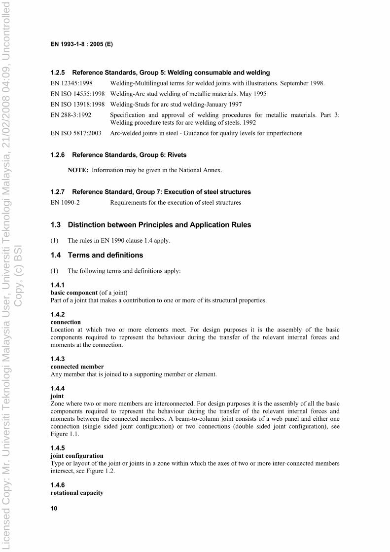
Zone where two or more members are interconnected. For design purposes it is the assembly of all the basic components required to represent the behaviour during the transfer of the relevant internal forces and moments between the connected members. A beam-to-column joint consists of a web panel and either one connection (single sided joint configuration) or two connections (double sided joint configuration), see Figure 1.1.
1.4.5 joint configuration
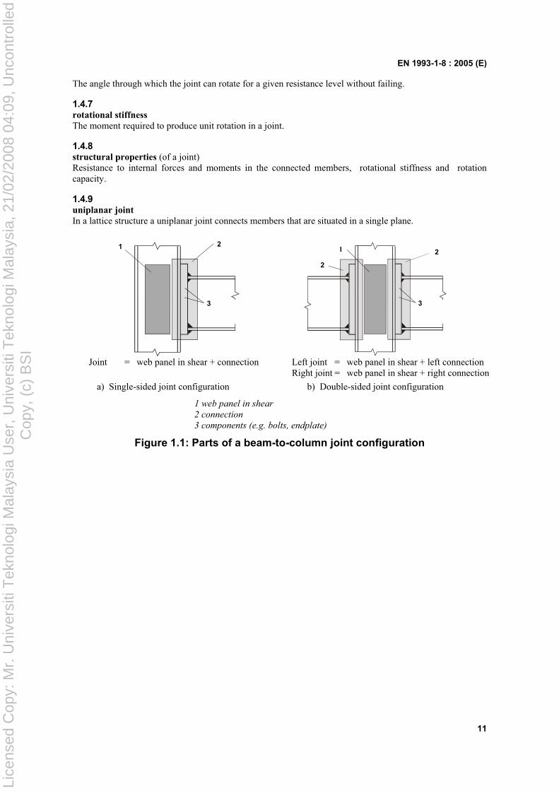
Type or layout of the joint or joints in a zone within which the axes of two or more inter-connected members intersect, see Figure 1.2.
1.4.6 rotational capacity
Lice
nsed
Cop
y: M
r. U
nive
rsiti
Tek
nolo
gi M
alay
sia
Use
r, U
nive
rsiti
Tek
nolo
gi M
alay
sia,
21/
02/2
008
04:0
9, U
ncon
trol
led
Cop
y, (
c) B
SI
EN 1993-1-8 : 2005 (E)
11
The angle through which the joint can rotate for a given resistance level without failing.
1.4.7 rotational stiffness
The moment required to produce unit rotation in a joint.
1.4.8 structural properties (of a joint) Resistance to internal forces and moments in the connected members, rotational stiffness and rotation capacity.
1.4.9 uniplanar joint
In a lattice structure a uniplanar joint connects members that are situated in a single plane.
21
3
2
3
1 2
Joint = web panel in shear + connection Left joint = web panel in shear + left connection Right joint = web panel in shear + right connection
a) Single-sided joint configuration b) Double-sided joint configuration
1 web panel in shear
2 connection
3 components (e.g. bolts, endplate)
Figure 1.1: Parts of a beam-to-column joint configuration
Lice
nsed
Cop
y: M
r. U
nive
rsiti
Tek
nolo
gi M
alay
sia
Use
r, U
nive
rsiti
Tek
nolo
gi M
alay
sia,
21/
02/2
008
04:0
9, U
ncon
trol
led
Cop
y, (
c) B
SI
EN 1993-1-8 : 2005 (E)
12
1
1
2
5
4
5
2
3 3 1 Single-sided beam-to-column joint
configuration;
2 Double-sided beam-to-column
joint configuration;
3 Beam splice;
4 Column splice;
5 Column base.
a) Major-axis joint configurations
Double-sided beam-to-column joint configuration
Double-sided beam-to-beam joint configuration
b) Minor-axis joint configurations (to be used only for balanced moments Mb1,Ed = Mb2,Ed )
Figure 1.2: Joint configurations
Lice
nsed
Cop
y: M
r. U
nive
rsiti
Tek
nolo
gi M
alay
sia
Use
r, U
nive
rsiti
Tek
nolo
gi M
alay
sia,
21/
02/2
008
04:0
9, U
ncon
trol
led
Cop
y, (
c) B
SI
EN 1993-1-8 : 2005 (E)
13
1.5 Symbols
(1) The following symbols are used in this Standard:
d is the nominal bolt diameter, the diameter of the pin or the diameter of the fastener;
d0 is the hole diameter for a bolt, a rivet or a pin ;
do,t is the hole size for the tension face, generally the hole diameter, but for a slotted holes perpendicular to the tension face the slot length should be used;
do,v is the hole size for the shear face, generally the hole diameter, but for slotted holes parallel to the shear face the slot length should be used;
dc is the clear depth of the column web;
dm is the mean of the across points and across flats dimensions of the bolt head or the nut, whichever is smaller;
fH,Rd is the design value of the Hertz pressure;
fur is the specified ultimate tensile strength of the rivet;
e1 is the end distance from the centre of a fastener hole to the adjacent end of any part, measured in the direction of load transfer, see Figure 3.1;
e2 is the edge distance from the centre of a fastener hole to the adjacent edge of any part, measured at right angles to the direction of load transfer, see Figure 3.1;
e3 is the distance from the axis of a slotted hole to the adjacent end or edge of any part, see Figure 3.1;
e4 is the distance from the centre of the end radius of a slotted hole to the adjacent end or edge of any part, see Figure 3.1;
eff is the effective length of fillet weld;
n is the number of the friction surfaces or the number of fastener holes on the shear face;
p1 is the spacing between centres of fasteners in a line in the direction of load transfer, see Figure 3.1;
p1,0 is the spacing between centres of fasteners in an outer line in the direction of load transfer, see Figure 3.1;
p1,i is the spacing between centres of fasteners in an inner line in the direction of load transfer, see Figure 3.1;
p2 is the spacing measured perpendicular to the load transfer direction between adjacent lines of fasteners, see Figure 3.1;
r is the bolt row number;
NOTE: In a bolted connection with more than one bolt-row in tension, the bolt-rows are numbered starting from the bolt-row furthest from the centre of compression.
ss is the length of stiff bearing;
ta is the thickness of the angle cleat;
tfc is the thickness of the column flange;
tp is the thickness of the plate under the bolt or the nut;
tw is the thickness of the web or bracket;
twc is the thickness of the column web;
A is the gross cross-section area of bolt;
A0 is the area of the rivet hole;
Avc is the shear area of the column, see EN 1993-1-1;
As is the tensile stress area of the bolt or of the anchor bolt;
Lice
nsed
Cop
y: M
r. U
nive
rsiti
Tek
nolo
gi M
alay
sia
Use
r, U
nive
rsiti
Tek
nolo
gi M
alay
sia,
21/
02/2
008
04:0
9, U
ncon
trol
led
Cop
y, (
c) B
SI
EN 1993-1-8 : 2005 (E)
14
Av,eff is the effective shear area;
Bp,Rd is the design punching shear resistance of the bolt head and the nut
E is the elastic modulus;
Fp,Cd is the design preload force;
Ft,Ed is the design tensile force per bolt for the ultimate limit state;
Ft,Rd is the design tension resistance per bolt;
FT,Rd is the tension resistance of an equivalent T-stub flange;
Fv,Rd is the design shear resistance per bolt;
Fb,Rd is the design bearing resistance per bolt;
Fs,Rd,ser is the design slip resistance per bolt at the serviceability limit state;
Fs,Rd is the design slip resistance per bolt at the ultimate limit state;
Fv,Ed,ser is the design shear force per bolt for the serviceability limit state;
Fv,Ed is the design shear force per bolt for the ultimate limit state;
Mj,Rd is the design moment resistance of a joint;
Sj is the rotational stiffness of a joint;
Sj,ini is the initial rotational stiffness of a joint;
Vwp,Rd is the plastic shear resistance of a column web panel;
z is the lever arm;
µ is the slip factor;
is the rotation of a joint.
(2) The following standard abbreviations for hollow sections are used in section 7:
CHS for “circular hollow section”;
RHS for “rectangular hollow section”, which in this context includes square hollow sections.
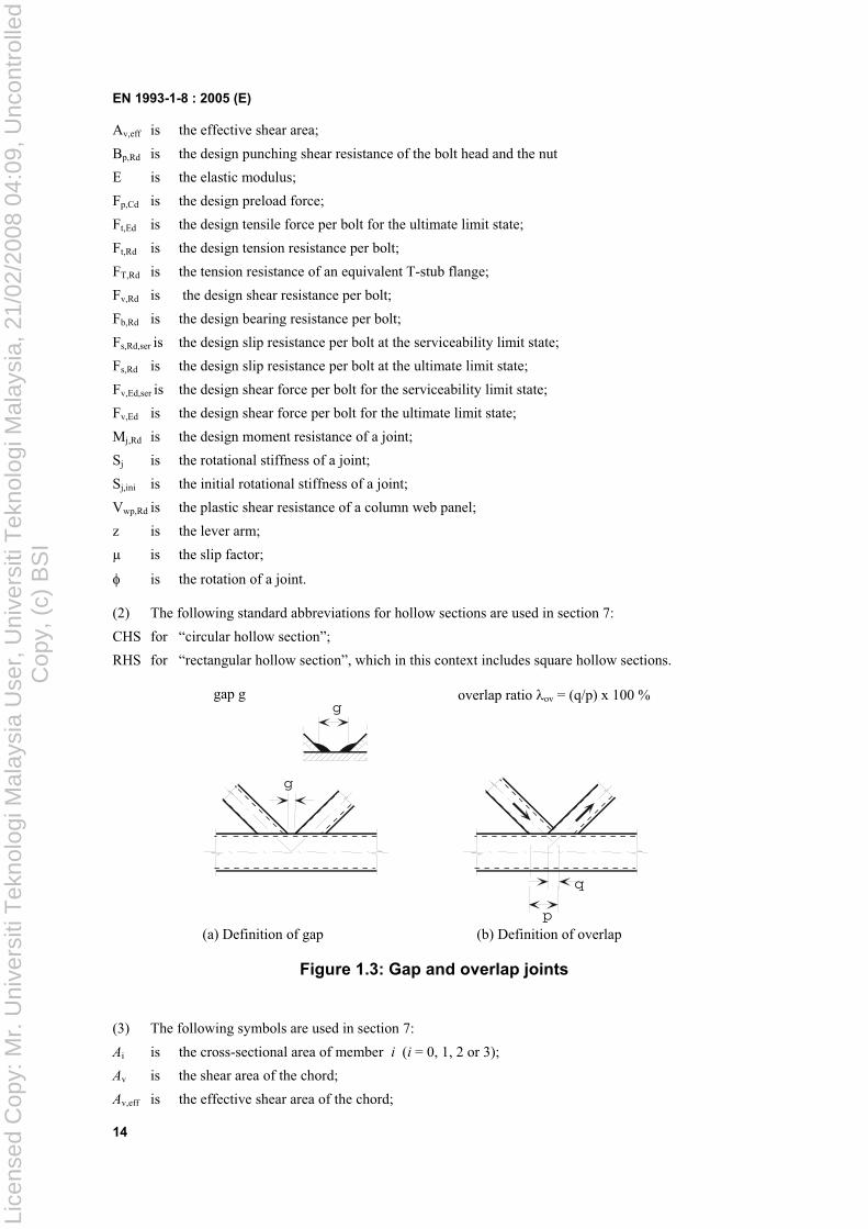
gap g overlap ratio ov = (q/p) x 100 %
g
q
p
g
(a) Definition of gap (b) Definition of overlap
Figure 1.3: Gap and overlap joints
(3) The following symbols are used in section 7:
Ai is the cross-sectional area of member i (i = 0, 1, 2 or 3);
Av is the shear area of the chord;
Av,eff is the effective shear area of the chord;
Lice
nsed
Cop
y: M
r. U
nive
rsiti
Tek
nolo
gi M
alay
sia
Use
r, U
nive
rsiti
Tek
nolo
gi M
alay
sia,
21/
02/2
008
04:0
9, U
ncon
trol
led
Cop
y, (
c) B
SI
EN 1993-1-8 : 2005 (E)
15
L is the system length of a member;
Mip,i,Rd is the design value of the resistance of the joint, expressed in terms of the in-plane internal moment in member i (i = 0, 1, 2 or 3);
Mip,i,Ed is the design value of the in-plane internal moment in member i (i = 0, 1, 2 or 3);
Mop,i,Rd is the design value of the resistance of the joint, expressed in terms of the out-of-plane internal moment in member i (i = 0, 1, 2 or 3);
Mop,i,Ed is the design value of the out-of-plane internal moment in member i (i = 0, 1, 2 or 3);
Ni,Rd is the design value of the resistance of the joint, expressed in terms of the internal axial force in member i (i = 0, 1, 2 or 3);
Ni,Ed is the design value of the internal axial force in member i (i = 0, 1, 2 or 3);
We ,i is the elastic section modulus of member i (i = 0, 1, 2 or 3);
Wp ,i is the plastic section modulus of member i (i = 0, 1, 2 or 3);
bi is the overall out-of-plane width of RHS member i (i = 0, 1, 2 or 3);
beff is the effective width for a brace member to chord connection;
be,ov is the effective width for an overlapping brace to overlapped brace connection;
be,p is the effective width for punching shear;
bp is the width of a plate;
bw is the effective width for the web of the chord;
di is the overall diameter of CHS member i (i = 0, 1, 2 or 3);
dw is the depth of the web of an I or H section chord member;
e is the eccentricity of a joint;
fb is the buckling strength of the chord side wall;
fyi is the yield strength of member i (i = 0, 1, 2 or 3);
fy0 is the yield strength of a chord member;
g is the gap between the brace members in a K or N joint (negative values of g represent an overlap q ); the gap g is measured along the length of the connecting face of the chord, between the toes of the adjacent brace members, see Figure 1.3(a);
hi is the overall in-plane depth of the cross-section of member i (i = 0, 1, 2 or 3);
k is a factor defined in the relevant table, with subscript g, m, n or p ;
is the buckling length of a member;
p is the length of the projected contact area of the overlapping brace member onto the face of the chord, in the absence of the overlapped brace member, see Figure 1.3(b);
q is the length of overlap, measured at the face of the chord, between the brace members in a K or N joint, see Figure 1.3(b);
r is the root radius of an I or H section or the corner radius of a rectangular hollow section;
tf is the flange thickness of an I or H section;
ti is the wall thickness of member i (i = 0, 1, 2 or 3);
tp is the thickness of a plate;
tw is the web thickness of an I or H section;
is a factor defined in the relevant table;
i is the included angle between brace member i and the chord (i = 1, 2 or 3);
is a factor defined where it occurs;
µ is a factor defined in the relevant table;
is the angle between the planes in a multiplanar joint.
Lice
nsed
Cop
y: M
r. U
nive
rsiti
Tek
nolo
gi M
alay
sia
Use
r, U
nive
rsiti
Tek
nolo
gi M
alay
sia,
21/
02/2
008
04:0
9, U
ncon
trol
led
Cop
y, (
c) B
SI

EN 1993-1-8 : 2005 (E)
16
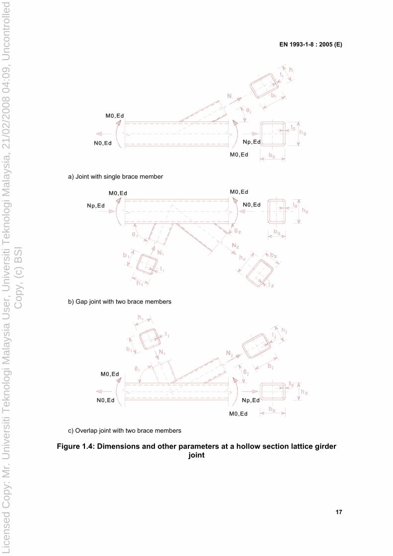
(4) The integer subscripts used in section 7 are defined as follows:
i is an integer subscript used to designate a member of a joint, i = 0 denoting a chord and i = 1, 2 or 3 the brace members. In joints with two brace members, i = 1 normally denotes the compression brace and i = 2 the tension brace, see Figure 1.4(b). For a single brace i = 1 whether it is subject to compression or tension, see Figure 1.4(a);
i and j are integer subscripts used in overlap type joints, i to denote the overlapping brace member and j to denote the overlapped brace member, see Figure 1.4(c).
(5) The stress ratios used in section 7 are defined as follows:
n is the ratio ( 0,Ed/ fy0) / M5 (used for RHS chords);
np is the ratio ( p,Ed/ fy0) / M5 (used for CHS chords);
0,Ed is the maximum compressive stress in the chord at a joint;
p,Ed is the value of 0,Ed excluding the stress due to the components parallel to the chord axis of the axial forces in the braces at that joint, see Figure 1.4.
(6) The geometric ratios used in section 7 are defined as follows:
is the ratio of the mean diameter or width of the brace members, to that of the chord:
- for T, Y and X joints:
0
1
d
d ;
0
1
b
d or
0
1
b
b
- for K and N joints:
0
21
2 d
dd ;
0
21
2 b
dd or
0
2121
4 b
hhbb
- for KT joints:
0
321
3 d
ddd ;
0
321
3 b
ddd or
0
321321
6 b
hhhbbb
p is the ratio bi /bp ;
is the ratio of the chord width or diameter to twice its wall thickness:
0
0
2 t
d ;
0
0
2 t
b or
ft
b
20
is the ratio of the brace member depth to the chord diameter or width:
0d
hi or 0b
hi
p is the ratio hi /bp;
ov is the overlap ratio, expressed as a percentage ( ov = (q/p) x 100%) as shown in figure 1.3(b).
(7) Other symbols are specified in appropriate clauses when they are used.
NOTE: Symbols for circular sections are given in Table 7.2.
Lice
nsed
Cop
y: M
r. U
nive
rsiti
Tek
nolo
gi M
alay
sia
Use
r, U
nive
rsiti
Tek
nolo
gi M
alay
sia,
21/
02/2
008
04:0
9, U
ncon
trol
led
Cop
y, (
c) B
SI
EN 1993-1-8 : 2005 (E)
17
a) Joint with single brace member
b) Gap joint with two brace members
c) Overlap joint with two brace members
Figure 1.4: Dimensions and other parameters at a hollow section lattice girder joint
Lice
nsed
Cop
y: M
r. U
nive
rsiti
Tek
nolo
gi M
alay
sia
Use
r, U
nive
rsiti
Tek
nolo
gi M
alay
sia,
21/
02/2
008
04:0
9, U
ncon
trol
led
Cop
y, (
c) B
SI
EN 1993-1-8 : 2005 (E)
18
2 Basis of design
2.1 Assumptions
(1) The design methods given in this part of EN 1993 assume that the standard of construction is as specified in the execution standards given in 1.2 and that the construction materials and products used are those specified in EN 1993 or in the relevant material and product specifications.
2.2 General requirements
(1)P All joints shall have a design resistance such that the structure is capable of satisfying all the basicdesign requirements given in this Standard and in EN 1993-1-1.
(2) The partial safety factors M for joints are given in Table 2.1.
Table 2.1: Partial safety factors for joints
Resistance of members and cross-sections M0 , M1 and M2 see EN 1993-1-1
Resistance of bolts
Resistance of rivets
Resistance of pins M2
Resistance of welds
Resistance of plates in bearing
Slip resistance - at ultimate limit state (Category C) - at serviceability limit state (Category B)
M3
M3,ser
Bearing resistance of an injection bolt M4
Resistance of joints in hollow section lattice girder M5
Resistance of pins at serviceability limit state M6,ser
Preload of high strength bolts M7
Resistance of concrete c see EN 1992
NOTE: Numerical values for M may be defined in the National Annex. Recommended values are as follows: M2 = 1,25 ; M3 = 1,25 and M3,ser = 1,1 ; M4 = 1,0 ; M5 = 1,0 ; M6,ser = 1,0 ; M7 = 1,1 .
(3)P Joints subject to fatigue shall also satisfy the principles given in EN 1993-1-9.
2.3 Applied forces and moments
(1)P The forces and moments applied to joints at the ultimate limit state shall be determined according tothe principles in EN 1993-1-1.
2.4 Resistance of joints
(1) The resistance of a joint should be determined on the basis of the resistances of its basic components.
(2) Linear-elastic or elastic-plastic analysis may be used in the design of joints.
Lice
nsed
Cop
y: M
r. U
nive
rsiti
Tek
nolo
gi M
alay
sia
Use
r, U
nive
rsiti
Tek
nolo
gi M
alay
sia,
21/
02/2
008
04:0
9, U
ncon
trol
led
Cop
y, (
c) B
SI
EN 1993-1-8 : 2005 (E)
19
(3) Where fasteners with different stiffnesses are used to carry a shear load the fasteners with the highest stiffness should be designed to carry the design load. An exception to this design method is given in 3.9.3.
2.5 Design assumptions
(1)P Joints shall be designed on the basis of a realistic assumption of the distribution of internal forcesand moments. The following assumptions shall be used to determine the distribution of forces:
(a) the internal forces and moments assumed in the analysis are in equilibrium with the forces and moments applied to the joints,
(b) each element in the joint is capable of resisting the internal forces and moments,
(c) the deformations implied by this distribution do not exceed the deformation capacity of the fasteners or welds and the connected parts,
(d) the assumed distribution of internal forces shall be realistic with regard to relative stiffnesseswithin the joint,
(e) the deformations assumed in any design model based on elastic-plastic analysis are based on rigid body rotations and/or in-plane deformations which are physically possible, and
(f) any model used is in compliance with the evaluation of test results (see EN 1990).
(2) The application rules given in this part satisfy 2.5(1).
2.6 Joints loaded in shear subject to impact, vibration and/or load reversal
(1) Where a joint loaded in shear is subject to impact or significant vibration one of the following jointing methods should be used:
– welding
– bolts with locking devices
– preloaded bolts
– injection bolts
– other types of bolt which effectively prevent movement of the connected parts
– rivets.
(2) Where slip is not acceptable in a joint (because it is subject to reversal of shear load or for any other reason), preloaded bolts in a Category B or C connection (see 3.4), fit bolts (see 3.6.1), rivets or welding should be used.
(3) For wind and/or stability bracings, bolts in Category A connections (see 3.4) may be used.
2.7 Eccentricity at intersections
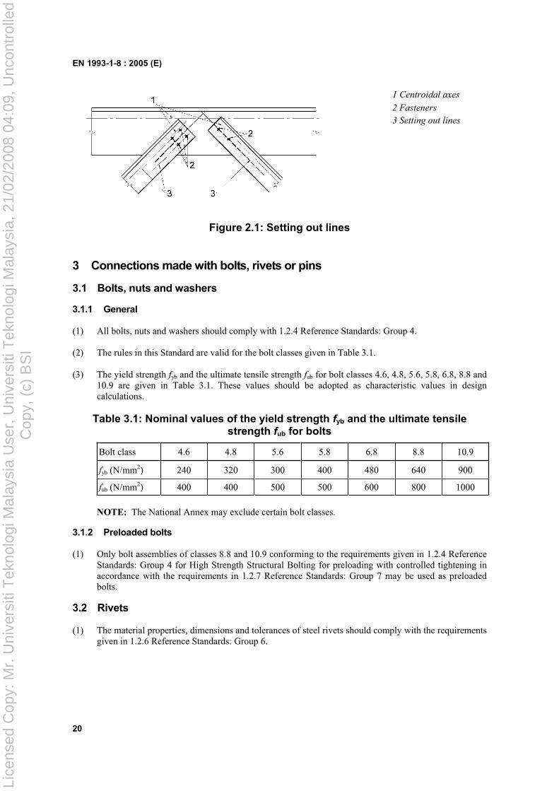
(1) Where there is eccentricity at intersections, the joints and members should be designed for the resulting moments and forces, except in the case of particular types of structures where it has been demonstrated that it is not necessary, see 5.1.5.
(2) In the case of joints of angles or tees attached by either a single line of bolts or two lines of bolts any possible eccentricity should be taken into account in accordance with 2.7(1). In-plane and out-of-plane eccentricities should be determined by considering the relative positions of the centroidal axis of the member and of the setting out line in the plane of the connection (see Figure 2.1). For a single angle in tension connected by bolts on one leg the simplified design method given in 3.10.3 may be used.
NOTE: The effect of eccentricity on angles used as web members in compression is given in EN 1993-1-1, Annex BB 1.2.
Lice
nsed
Cop
y: M
r. U
nive
rsiti
Tek
nolo
gi M
alay
sia
Use
r, U
nive
rsiti
Tek
nolo
gi M
alay
sia,
21/
02/2
008
04:0
9, U
ncon
trol
led
Cop
y, (
c) B
SI
EN 1993-1-8 : 2005 (E)
20
1 Centroidal axes
2 Fasteners
3 Setting out lines
Figure 2.1: Setting out lines
3 Connections made with bolts, rivets or pins
3.1 Bolts, nuts and washers
3.1.1 General
(1) All bolts, nuts and washers should comply with 1.2.4 Reference Standards: Group 4.
(2) The rules in this Standard are valid for the bolt classes given in Table 3.1.
(3) The yield strength fyb and the ultimate tensile strength fub for bolt classes 4.6, 4.8, 5.6, 5.8, 6.8, 8.8 and 10.9 are given in Table 3.1. These values should be adopted as characteristic values in design calculations.
Table 3.1: Nominal values of the yield strength fyb and the ultimate tensile strength fub for bolts
Bolt class 4.6 4.8 5.6 5.8 6.8 8.8 10.9
fyb (N/mm2) 240 320 300 400 480 640 900
fub (N/mm2) 400 400 500 500 600 800 1000
NOTE: The National Annex may exclude certain bolt classes.
3.1.2 Preloaded bolts
(1) Only bolt assemblies of classes 8.8 and 10.9 conforming to the requirements given in 1.2.4 Reference Standards: Group 4 for High Strength Structural Bolting for preloading with controlled tightening in accordance with the requirements in 1.2.7 Reference Standards: Group 7 may be used as preloaded bolts.
3.2 Rivets
(1) The material properties, dimensions and tolerances of steel rivets should comply with the requirements given in 1.2.6 Reference Standards: Group 6.
Lice
nsed
Cop
y: M
r. U
nive
rsiti
Tek
nolo
gi M
alay
sia
Use
r, U
nive
rsiti
Tek
nolo
gi M
alay
sia,
21/
02/2
008
04:0
9, U
ncon
trol
led
Cop
y, (
c) B
SI
EN 1993-1-8 : 2005 (E)
21
3.3 Anchor bolts
(1) The following materials may be used for anchor bolts:
– Steel grades conforming to 1.2.1 Reference Standards: Group 1;
– Steel grades conforming to 1.2.4 Reference Standards: Group 4;
– Steel grades used for reinforcing bars conforming to EN 10080;
provided that the nominal yield strength does not exceed 640 N/mm2 when the anchor bolts are required to act in shear and not more than 900 N/mm2 otherwise.
3.4 Categories of bolted connections
3.4.1 Shear connections
(1) Bolted connections loaded in shear should be designed as one of the following:
a) Category A: Bearing type
In this category bolts from class 4.6 up to and including class 10.9 should be used. No preloading and special provisions for contact surfaces are required. The design ultimate shear load should not exceed the design shear resistance, obtained from 3.6, nor the design bearing resistance, obtained from 3.6 and 3.7.
b) Category B: Slip-resistant at serviceability limit state
In this category preloaded bolts in accordance with 3.1.2(1) should be used. Slip should not occur at the serviceability limit state. The design serviceability shear load should not exceed the design slip resistance, obtained from 3.9. The design ultimate shear load should not exceed the design shear resistance, obtained from 3.6, nor the design bearing resistance, obtained from 3.6 and 3.7.
c) Category C: Slip-resistant at ultimate limit state
In this category preloaded bolts in accordance with 3.1.2(1) should be used. Slip should not occur at the ultimate limit state. The design ultimate shear load should not exceed the design slip resistance, obtained from 3.9, nor the design bearing resistance, obtained from 3.6 and 3.7. In addition for a connection in tension, the design plastic resistance of the net cross-section at bolt holes Nnet,Rd, (see 6.2 of EN 1993-1-1), should be checked, at the ultimate limit state.
The design checks for these connections are summarized in Table 3.2.
3.4.2 Tension connections
(1) Bolted connection loaded in tension should be designed as one of the following:
a) Category D: non-preloaded
In this category bolts from class 4.6 up to and including class 10.9 should be used. No preloading is required. This category should not be used where the connections are frequently subjected to variations of tensile loading. However, they may be used in connections designed to resist normal wind loads.
b) Category E: preloaded
In this category preloaded 8.8 and 10.9 bolts with controlled tightening in conformity with 1.2.7 Reference Standards: Group 7 should be used.
The design checks for these connections are summarized in Table 3.2.
Lice
nsed
Cop
y: M
r. U
nive
rsiti
Tek
nolo
gi M
alay
sia
Use
r, U
nive
rsiti
Tek
nolo
gi M
alay
sia,
21/
02/2
008
04:0
9, U
ncon
trol
led
Cop
y, (
c) B
SI
EN 1993-1-8 : 2005 (E)
22
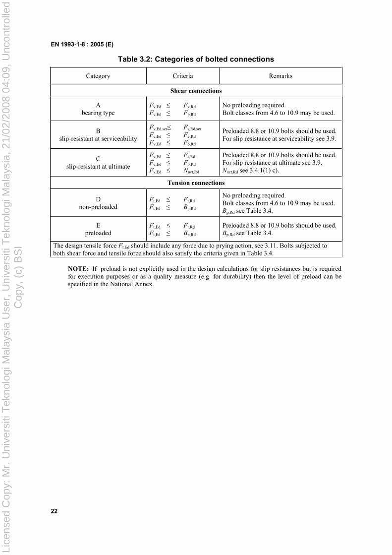
Table 3.2: Categories of bolted connections
Category Criteria Remarks
Shear connections
Abearing type
Fv,Ed Fv,Rd
Fv,Ed Fb,Rd
No preloading required. Bolt classes from 4.6 to 10.9 may be used.
Bslip-resistant at serviceability
Fv,Ed.ser Fs,Rd,ser
Fv,Ed Fv,Rd
Fv,Ed Fb,Rd
Preloaded 8.8 or 10.9 bolts should be used. For slip resistance at serviceability see 3.9.
Cslip-resistant at ultimate
Fv,Ed Fs,Rd
Fv,Ed Fb,Rd
Fv,Ed Nnet,Rd
Preloaded 8.8 or 10.9 bolts should be used. For slip resistance at ultimate see 3.9. Nnet,Rd see 3.4.1(1) c).
Tension connections
Dnon-preloaded
Ft,Ed Ft,Rd
Ft,Ed Bp,Rd
No preloading required. Bolt classes from 4.6 to 10.9 may be used. Bp,Rd see Table 3.4.
Epreloaded
Ft,Ed Ft,Rd
Ft,Ed Bp,Rd
Preloaded 8.8 or 10.9 bolts should be used. Bp,Rd see Table 3.4.
The design tensile force Ft,Ed should include any force due to prying action, see 3.11. Bolts subjected to both shear force and tensile force should also satisfy the criteria given in Table 3.4.
NOTE: If preload is not explicitly used in the design calculations for slip resistances but is required for execution purposes or as a quality measure (e.g. for durability) then the level of preload can be specified in the National Annex.
Lice
nsed
Cop
y: M
r. U
nive
rsiti
Tek
nolo
gi M
alay
sia
Use
r, U
nive
rsiti
Tek
nolo
gi M
alay
sia,
21/
02/2
008
04:0
9, U
ncon
trol
led
Cop
y, (
c) B
SI
EN 1993-1-8 : 2005 (E)
23
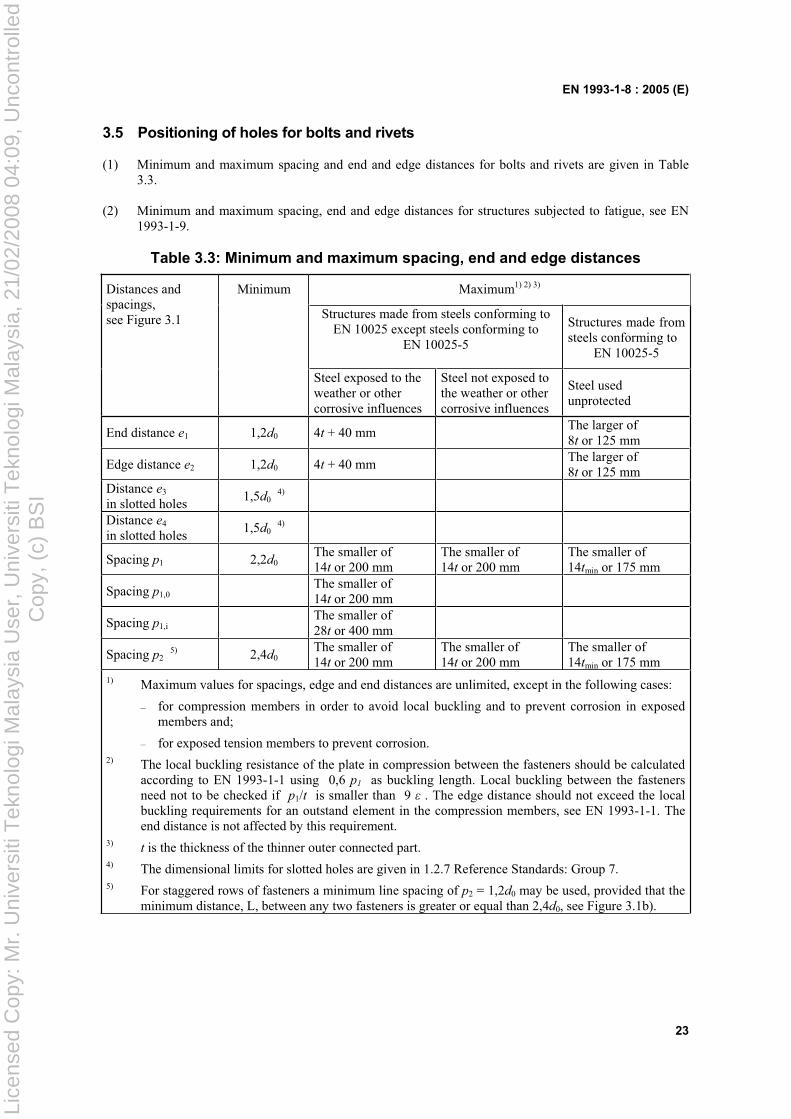
3.5 Positioning of holes for bolts and rivets
(1) Minimum and maximum spacing and end and edge distances for bolts and rivets are given in Table 3.3.
(2) Minimum and maximum spacing, end and edge distances for structures subjected to fatigue, see EN 1993-1-9.
Table 3.3: Minimum and maximum spacing, end and edge distances
Minimum Maximum1) 2) 3)
Structures made from steels conforming to EN 10025 except steels conforming to
EN 10025-5
Structures made from steels conforming to
EN 10025-5
Distances and spacings, see Figure 3.1
Steel exposed to the weather or other corrosive influences
Steel not exposed to the weather or other corrosive influences
Steel used unprotected
End distance e1 1,2d0 4t + 40 mmThe larger of 8t or 125 mm
Edge distance e2 1,2d0 4t + 40 mmThe larger of 8t or 125 mm
Distance e3
in slotted holes1,5d0
4)
Distance e4
in slotted holes1,5d0
4)
Spacing p1 2,2d0The smaller of 14t or 200 mm
The smaller of 14t or 200 mm
The smaller of 14tmin or 175 mm
Spacing p1,0The smaller of 14t or 200 mm
Spacing p1,iThe smaller of 28t or 400 mm
Spacing p25) 2,4d0
The smaller of 14t or 200 mm
The smaller of 14t or 200 mm
The smaller of 14tmin or 175 mm
1) Maximum values for spacings, edge and end distances are unlimited, except in the following cases:
– for compression members in order to avoid local buckling and to prevent corrosion in exposed members and;
– for exposed tension members to prevent corrosion. 2) The local buckling resistance of the plate in compression between the fasteners should be calculated
according to EN 1993-1-1 using 0,6 p1 as buckling length. Local buckling between the fasteners need not to be checked if p1/t is smaller than 9 . The edge distance should not exceed the local buckling requirements for an outstand element in the compression members, see EN 1993-1-1. The end distance is not affected by this requirement.
3) t is the thickness of the thinner outer connected part. 4) The dimensional limits for slotted holes are given in 1.2.7 Reference Standards: Group 7. 5) For staggered rows of fasteners a minimum line spacing of p2 = 1,2d0 may be used, provided that the
minimum distance, L, between any two fasteners is greater or equal than 2,4d0, see Figure 3.1b).
Lice
nsed
Cop
y: M
r. U
nive
rsiti
Tek
nolo
gi M
alay
sia
Use
r, U
nive
rsiti
Tek
nolo
gi M
alay
sia,
21/
02/2
008
04:0
9, U
ncon
trol
led
Cop
y, (
c) B
SI
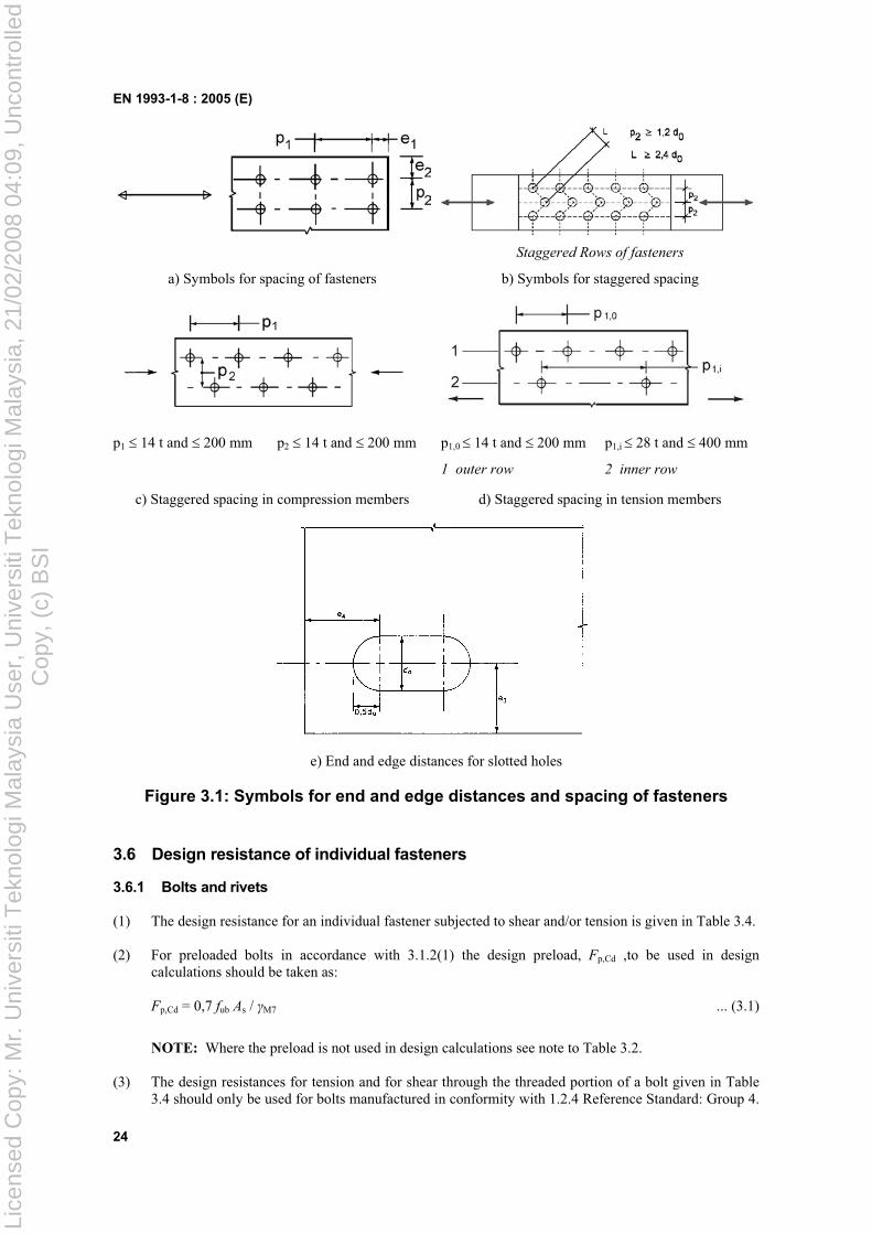
EN 1993-1-8 : 2005 (E)
24
Staggered Rows of fasteners
a) Symbols for spacing of fasteners b) Symbols for staggered spacing
p1 14 t and 200 mm p2 14 t and 200 mm p1,0 14 t and 200 mm p1,i 28 t and 400 mm
1 outer row 2 inner row
c) Staggered spacing in compression members d) Staggered spacing in tension members
e) End and edge distances for slotted holes
Figure 3.1: Symbols for end and edge distances and spacing of fasteners
3.6 Design resistance of individual fasteners
3.6.1 Bolts and rivets
(1) The design resistance for an individual fastener subjected to shear and/or tension is given in Table 3.4.
(2) For preloaded bolts in accordance with 3.1.2(1) the design preload, Fp,Cd ,to be used in design calculations should be taken as:
Fp,Cd = 0,7 fub As / M7 ... (3.1)
NOTE: Where the preload is not used in design calculations see note to Table 3.2.
(3) The design resistances for tension and for shear through the threaded portion of a bolt given in Table 3.4 should only be used for bolts manufactured in conformity with 1.2.4 Reference Standard: Group 4.
Lice
nsed
Cop
y: M
r. U
nive
rsiti
Tek
nolo
gi M
alay
sia
Use
r, U
nive
rsiti
Tek
nolo
gi M
alay
sia,
21/
02/2
008
04:0
9, U
ncon
trol
led
Cop
y, (
c) B
SI
EN 1993-1-8 : 2005 (E)
25
For bolts with cut threads, such as anchor bolts or tie rods fabricated from round steel bars where the threads comply with EN 1090, the relevant values from Table 3.4 should be used. For bolts with cut threads where the threads do not comply with EN 1090 the relevant values from Table 3.4 should be multiplied by a factor of 0,85.
(4) The design shear resistance Fv,Rd given in Table 3.4 should only be used where the bolts are used in holes with nominal clearances not exceeding those for normal holes as specified in 1.2.7 Reference Standards: Group 7.
(5) M12 and M14 bolts may also be used in 2 mm clearance holes provided that the design resistance of the bolt group based on bearing is greater or equal to the design resistance of the bolt group based on bolt shear. In addition for class 4.8, 5.8, 6.8, 8.8 and 10.9 bolts the design shear resistance Fv,Rd should be taken as 0,85 times the value given in Table 3.4.
(6) Fit bolts should be designed using the method for bolts in normal holes.
(7) The thread of a fit bolt should not be included in the shear plane.
(8) The length of the threaded portion of a fit bolt included in the bearing length should not exceed 1/3 of the thickness of the plate, see Figure 3.2.
(9) The hole tolerance used for fit bolts should be in accordance with 1.2.7 Reference Standards: Group 7.
(10) In single lap joints with only one bolt row, see Figure 3.3, the bolts should be provided with washers under both the head and the nut. The design bearing resistance Fb,Rd for each bolt should be limited to:
Fb,Rd 1,5 fu d t / M2 ... (3.2)
NOTE: Single rivets should not be used in single lap joints.
(11) In the case of class 8.8 or 10.9 bolts, hardened washers should be used for single lap joints with only one bolt or one row of bolts.
(12) Where bolts or rivets transmitting load in shear and bearing pass through packing of total thickness tp
greater than one-third of the nominal diameter d, see Figure 3.4, the design shear resistance Fv,Rd
calculated as specified in Table 3.4, should be multiplying by a reduction factor p given by:
p = ptd
d
38
9 but p 1 ... (3.3)
(13) For double shear connections with packing on both sides of the splice, tp should be taken as the thickness of the thicker packing.
(14) Riveted connections should be designed to transfer shear forces. If tension is present the design tensile force Ft.Ed should not exceed the design tension resistance Ft,Rd given in Table 3.4.
(15) For grade S 235 steel the "as driven" value of fur may be taken as 400 N/mm2.
(16) As a general rule, the grip length of a rivet should not exceed 4,5d for hammer riveting and 6,5d for press riveting.
Lice
nsed
Cop
y: M
r. U
nive
rsiti
Tek
nolo
gi M
alay
sia
Use
r, U
nive
rsiti
Tek
nolo
gi M
alay
sia,
21/
02/2
008
04:0
9, U
ncon
trol
led
Cop
y, (
c) B
SI
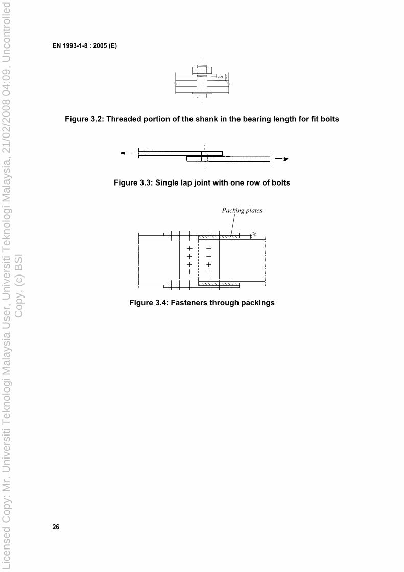
EN 1993-1-8 : 2005 (E)
26
t<t/3
Figure 3.2: Threaded portion of the shank in the bearing length for fit bolts
Figure 3.3: Single lap joint with one row of bolts
Packing plates
tp
Figure 3.4: Fasteners through packings
Lice
nsed
Cop
y: M
r. U
nive
rsiti
Tek
nolo
gi M
alay
sia
Use
r, U
nive
rsiti
Tek
nolo
gi M
alay
sia,
21/
02/2
008
04:0
9, U
ncon
trol
led
Cop
y, (
c) B
SI
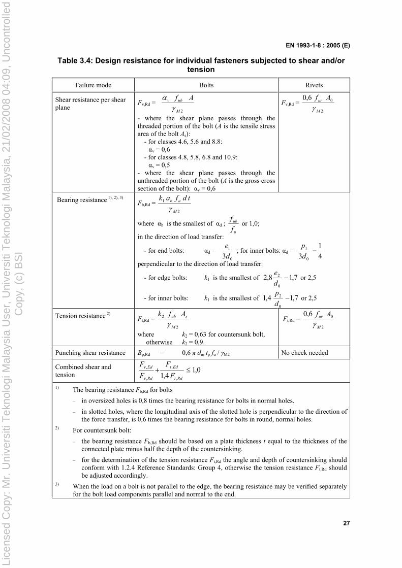
EN 1993-1-8 : 2005 (E)
27
Table 3.4: Design resistance for individual fasteners subjected to shear and/or tension
Failure mode Bolts Rivets
Shear resistance per shear plane
Fv,Rd = 2M
ubv Af
- where the shear plane passes through the threaded portion of the bolt (A is the tensile stress area of the bolt As):
- for classes 4.6, 5.6 and 8.8: v = 0,6
- for classes 4.8, 5.8, 6.8 and 10.9: v = 0,5
- where the shear plane passes through the unthreaded portion of the bolt (A is the gross cross section of the bolt): v = 0,6
Fv,Rd = 2
06,0
M
ur Af
Bearing resistance 1), 2), 3)
Fb,Rd = 2
1
M
ub tdfak
where b is the smallest of d ; u
ub
f
f or 1,0;
in the direction of load transfer:
- for end bolts: d = 0
1
3d
e ; for inner bolts: d =
4
1
3 0
1
d
p
perpendicular to the direction of load transfer:
- for edge bolts: k1 is the smallest of 7,18,20
2
d
e or 2,5
- for inner bolts: k1 is the smallest of 7,14,10
2
d
p or 2,5
Tension resistance 2)Ft,Rd =
2
2
M
sub Afk
where k2 = 0,63 for countersunk bolt, otherwise k2 = 0,9.
Ft,Rd = 2
06,0
M
ur Af
Punching shear resistance Bp,Rd = 0,6 dm tp fu / M2 No check needed
Combined shear and tension
0,14,1 ,
,
,
,
Rdt
Edt
Rdv
Edv
F
F
F
F
1) The bearing resistance Fb,Rd for bolts
– in oversized holes is 0,8 times the bearing resistance for bolts in normal holes.
– in slotted holes, where the longitudinal axis of the slotted hole is perpendicular to the direction of the force transfer, is 0,6 times the bearing resistance for bolts in round, normal holes.
2) For countersunk bolt:
– the bearing resistance Fb,Rd should be based on a plate thickness t equal to the thickness of the connected plate minus half the depth of the countersinking.
– for the determination of the tension resistance Ft,Rd the angle and depth of countersinking should conform with 1.2.4 Reference Standards: Group 4, otherwise the tension resistance Ft,Rd should be adjusted accordingly.
3) When the load on a bolt is not parallel to the edge, the bearing resistance may be verified separately for the bolt load components parallel and normal to the end.
Lice
nsed
Cop
y: M
r. U
nive
rsiti
Tek
nolo
gi M
alay
sia
Use
r, U
nive
rsiti
Tek
nolo
gi M
alay
sia,
21/
02/2
008
04:0
9, U
ncon
trol
led
Cop
y, (
c) B
SI
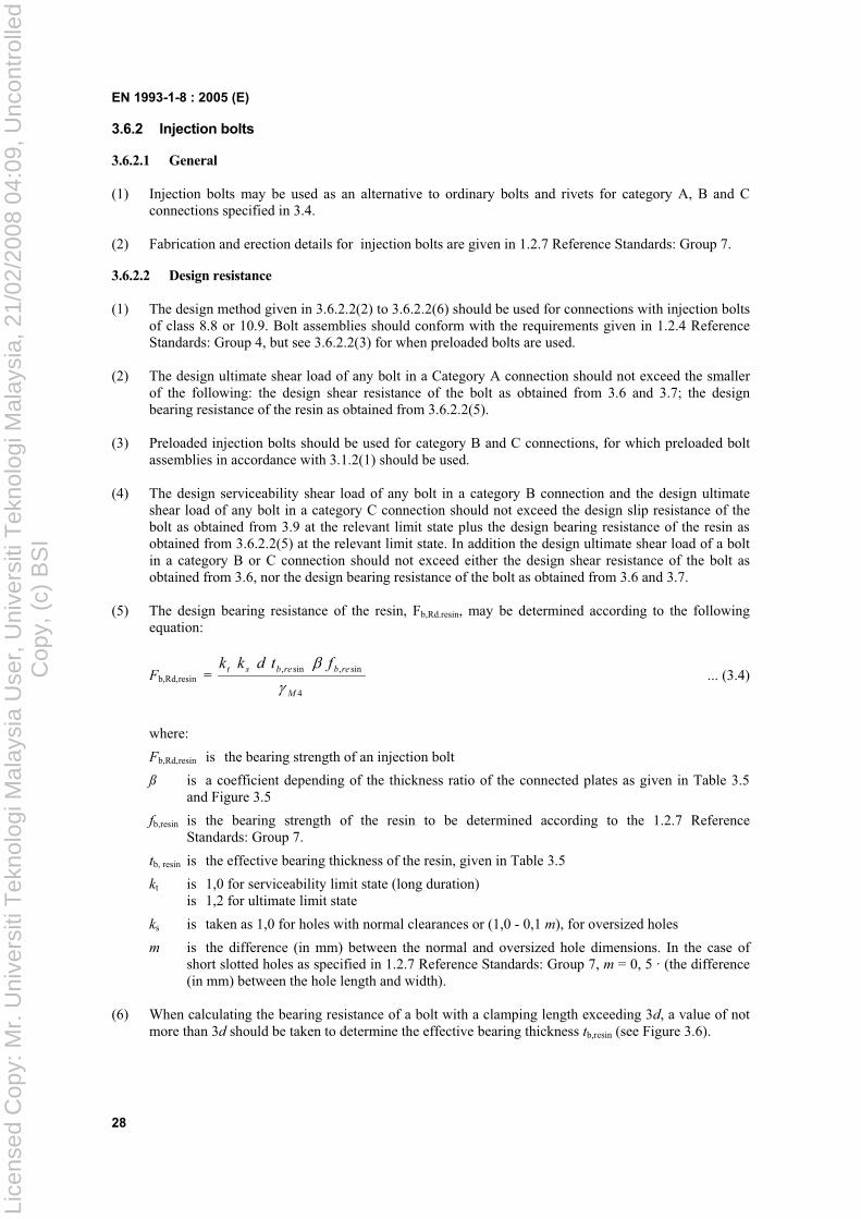
EN 1993-1-8 : 2005 (E)
28
3.6.2 Injection bolts
3.6.2.1 General
(1) Injection bolts may be used as an alternative to ordinary bolts and rivets for category A, B and C connections specified in 3.4.
(2) Fabrication and erection details for injection bolts are given in 1.2.7 Reference Standards: Group 7.
3.6.2.2 Design resistance
(1) The design method given in 3.6.2.2(2) to 3.6.2.2(6) should be used for connections with injection bolts of class 8.8 or 10.9. Bolt assemblies should conform with the requirements given in 1.2.4 Reference Standards: Group 4, but see 3.6.2.2(3) for when preloaded bolts are used.
(2) The design ultimate shear load of any bolt in a Category A connection should not exceed the smaller of the following: the design shear resistance of the bolt as obtained from 3.6 and 3.7; the design bearing resistance of the resin as obtained from 3.6.2.2(5).
(3) Preloaded injection bolts should be used for category B and C connections, for which preloaded bolt assemblies in accordance with 3.1.2(1) should be used.
(4) The design serviceability shear load of any bolt in a category B connection and the design ultimate shear load of any bolt in a category C connection should not exceed the design slip resistance of the bolt as obtained from 3.9 at the relevant limit state plus the design bearing resistance of the resin as obtained from 3.6.2.2(5) at the relevant limit state. In addition the design ultimate shear load of a bolt in a category B or C connection should not exceed either the design shear resistance of the bolt as obtained from 3.6, nor the design bearing resistance of the bolt as obtained from 3.6 and 3.7.
(5) The design bearing resistance of the resin, Fb,Rd.resin, may be determined according to the following equation:
Fb,Rd,resin = 4
sin,sin,
M
rebrebst ftdkk ... (3.4)
where:
Fb,Rd,resin is the bearing strength of an injection bolt
ß is a coefficient depending of the thickness ratio of the connected plates as given in Table 3.5 and Figure 3.5
fb,resin is the bearing strength of the resin to be determined according to the 1.2.7 Reference Standards: Group 7.
tb, resin is the effective bearing thickness of the resin, given in Table 3.5
kt is 1,0 for serviceability limit state (long duration) is 1,2 for ultimate limit state
ks is taken as 1,0 for holes with normal clearances or (1,0 - 0,1 m), for oversized holes
m is the difference (in mm) between the normal and oversized hole dimensions. In the case of short slotted holes as specified in 1.2.7 Reference Standards: Group 7, m = 0, 5 · (the difference (in mm) between the hole length and width).
(6) When calculating the bearing resistance of a bolt with a clamping length exceeding 3d, a value of not more than 3d should be taken to determine the effective bearing thickness tb,resin (see Figure 3.6).
Lice
nsed
Cop
y: M
r. U
nive
rsiti
Tek
nolo
gi M
alay
sia
Use
r, U
nive
rsiti
Tek
nolo
gi M
alay
sia,
21/
02/2
008
04:0
9, U
ncon
trol
led
Cop
y, (
c) B
SI
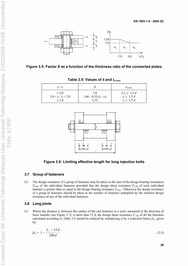
EN 1993-1-8 : 2005 (E)
29
1
112
2
2
1
2
2
1
2
t
t
t
t1.0
1,01,33
2.0 /
t
Figure 3.5: Factor ß as a function of the thickness ratio of the connected plates
Table 3.5: Values of ß and tb,resin
tl / t2 ß tb,resin
2,0 1,0 < tl / t2 < 2,0
1,0
1,01,66 - 0,33 (t1 / t2)
1,33
2 t2 1,5 dt1 1,5 dt1 1,5 d
Figure 3.6: Limiting effective length for long injection bolts
3.7 Group of fasteners
(1) The design resistance of a group of fasteners may be taken as the sum of the design bearing resistances Fb,Rd of the individual fasteners provided that the design shear resistance Fv,Rd of each individual fastener is greater than or equal to the design bearing resistance Fb,Rd . Otherwise the design resistance of a group of fasteners should be taken as the number of fasteners multiplied by the smallest design resistance of any of the individual fasteners.
3.8 Long joints
(1) Where the distance Lj between the centres of the end fasteners in a joint, measured in the direction of force transfer (see Figure 3.7), is more than 15 d, the design shear resistance Fv,Rd of all the fasteners calculated according to Table 3.4 should be reduced by multiplying it by a reduction factor Lf, given by:
Lf = d
dL j
200
151 ... (3.5)
Lice
nsed
Cop
y: M
r. U
nive
rsiti
Tek
nolo
gi M
alay
sia
Use
r, U
nive
rsiti
Tek
nolo
gi M
alay
sia,
21/
02/2
008
04:0
9, U
ncon
trol
led
Cop
y, (
c) B
SI
EN 1993-1-8 : 2005 (E)
30
but Lf 1,0 and Lf 0,75
(2) The provision in 3.8(1) does not apply where there is a uniform distribution of force transfer over the length of the joint, e.g. the transfer of shear force between the web and the flange of a section.
Figure 3.7: Long joints
3.9 Slip-resistant connections using 8.8 or 10.9 bolts
3.9.1 Design Slip resistance
(1) The design slip resistance of a preloaded class 8.8 or 10.9 bolt should be taken as:
Fs,Rd = 3M
s nkFp,C ... (3.6)
where:
ks is given in Table 3.6
n is the number of the friction surfaces
µ is the slip factor obtained either by specific tests for the friction surface in accordance with 1.2.7 Reference Standards: Group 7 or when relevant as given in Table 3.7.
(2) For class 8.8 and 10.9 bolts conforming with 1.2.4 Reference Standards: Group 4, with controlled tightening in conformity with 1.2.7 Reference Standards: Group 7, the preloading force Fp,C to be used in equation (3.6) should be taken as:
Fp,C = 0,7 fub As ... (3.7)
Table 3.6: Values of ks
Description ks
Bolts in normal holes. 1,0
Bolts in either oversized holes or short slotted holes with the axis of the slot perpendicular to the direction of load transfer.
0,85
Bolts in long slotted holes with the axis of the slot perpendicular to the direction of load transfer.
0,7
Bolts in short slotted holes with the axis of the slot parallel to the direction of load transfer.
0,76
Bolts in long slotted holes with the axis of the slot parallel to the direction of load transfer.
0,63
Lice
nsed
Cop
y: M
r. U
nive
rsiti
Tek
nolo
gi M
alay
sia
Use
r, U
nive
rsiti
Tek
nolo
gi M
alay
sia,
21/
02/2
008
04:0
9, U
ncon
trol
led
Cop
y, (
c) B
SI
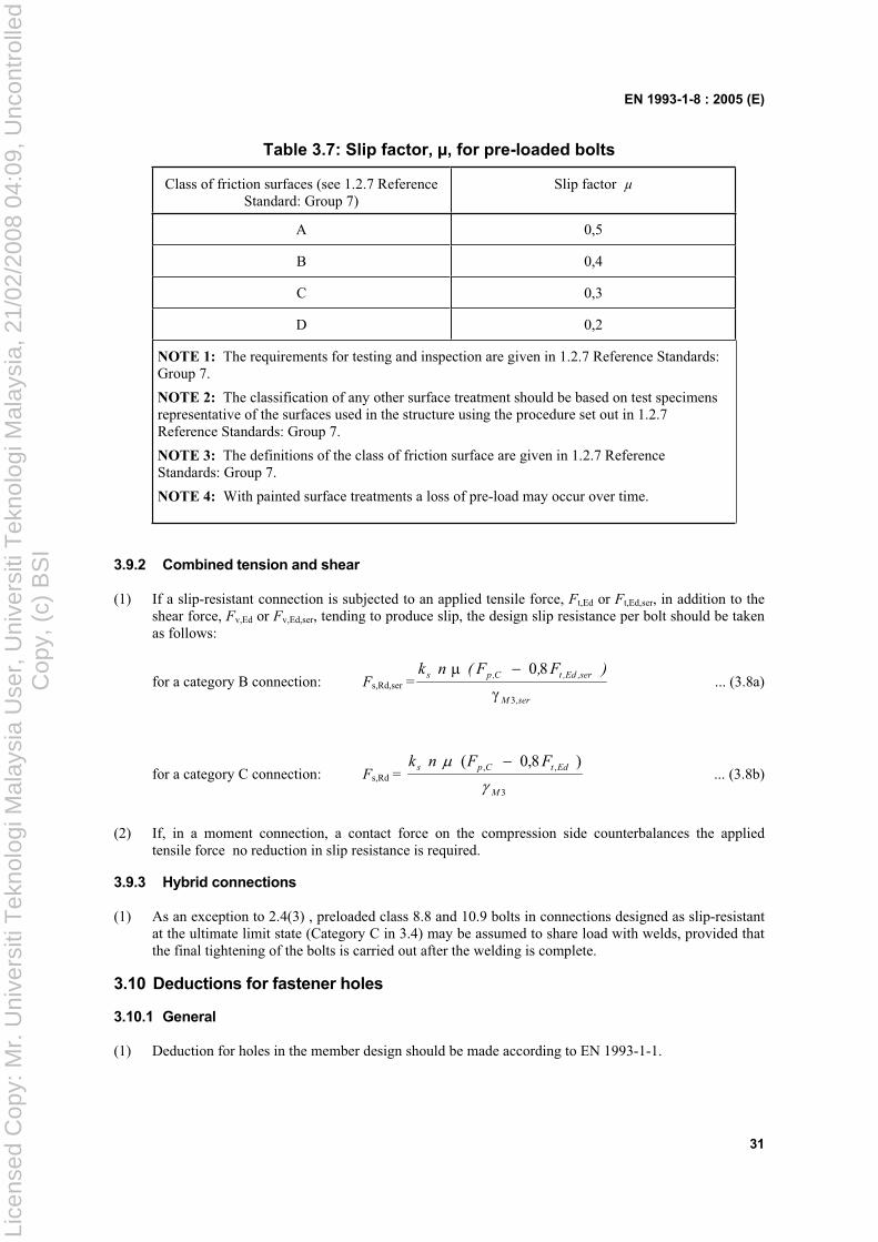
EN 1993-1-8 : 2005 (E)
31
Table 3.7: Slip factor, µ, for pre-loaded bolts
Class of friction surfaces (see 1.2.7 Reference Standard: Group 7)
Slip factor µ
A 0,5
B 0,4
C 0,3
D 0,2
NOTE 1: The requirements for testing and inspection are given in 1.2.7 Reference Standards: Group 7.
NOTE 2: The classification of any other surface treatment should be based on test specimens representative of the surfaces used in the structure using the procedure set out in 1.2.7 Reference Standards: Group 7.
NOTE 3: The definitions of the class of friction surface are given in 1.2.7 Reference Standards: Group 7.
NOTE 4: With painted surface treatments a loss of pre-load may occur over time.
3.9.2 Combined tension and shear
(1) If a slip-resistant connection is subjected to an applied tensile force, Ft,Ed or Ft,Ed,ser, in addition to the shear force, Fv,Ed or Fv,Ed,ser, tending to produce slip, the design slip resistance per bolt should be taken as follows:
for a category B connection: Fs,Rd,ser =ser,M
ser,Ed,tC,ps )F,F(nk
3
80 ... (3.8a)
for a category C connection: Fs,Rd = 3
,, )8,0(
M
EdtCps FFnk ... (3.8b)
(2) If, in a moment connection, a contact force on the compression side counterbalances the applied tensile force no reduction in slip resistance is required.
3.9.3 Hybrid connections
(1) As an exception to 2.4(3) , preloaded class 8.8 and 10.9 bolts in connections designed as slip-resistant at the ultimate limit state (Category C in 3.4) may be assumed to share load with welds, provided that the final tightening of the bolts is carried out after the welding is complete.
3.10 Deductions for fastener holes
3.10.1 General
(1) Deduction for holes in the member design should be made according to EN 1993-1-1.
Lice
nsed
Cop
y: M
r. U
nive
rsiti
Tek
nolo
gi M
alay
sia
Use
r, U
nive
rsiti
Tek
nolo
gi M
alay
sia,
21/
02/2
008
04:0
9, U
ncon
trol
led
Cop
y, (
c) B
SI
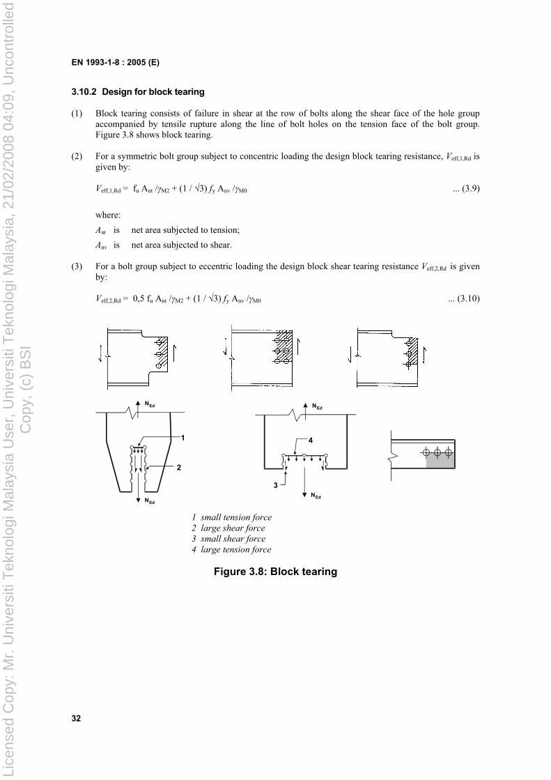
EN 1993-1-8 : 2005 (E)
32
3.10.2 Design for block tearing
(1) Block tearing consists of failure in shear at the row of bolts along the shear face of the hole group accompanied by tensile rupture along the line of bolt holes on the tension face of the bolt group. Figure 3.8 shows block tearing.
(2) For a symmetric bolt group subject to concentric loading the design block tearing resistance, Veff,1,Rd is given by:
Veff,1,Rd = fu Ant / M2 + (1 / 3) fy Anv / M0 ... (3.9)
where:
Ant is net area subjected to tension;
Anv is net area subjected to shear.
(3) For a bolt group subject to eccentric loading the design block shear tearing resistance Veff,2,Rd is given by:
Veff,2,Rd = 0,5 fu Ant / M2 + (1 / 3) fy Anv / M0 ... (3.10)
3
4
NEd
NEd
1
2
NEd
NEd
1 small tension force
2 large shear force
3 small shear force
4 large tension force
Figure 3.8: Block tearing
Lice
nsed
Cop
y: M
r. U
nive
rsiti
Tek
nolo
gi M
alay
sia
Use
r, U
nive
rsiti
Tek
nolo
gi M
alay
sia,
21/
02/2
008
04:0
9, U
ncon
trol
led
Cop
y, (
c) B
SI
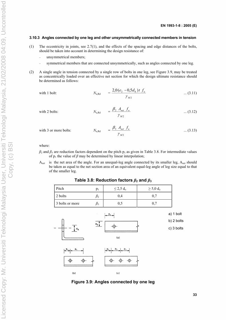
EN 1993-1-8 : 2005 (E)
33
3.10.3 Angles connected by one leg and other unsymmetrically connected members in tension
(1) The eccentricity in joints, see 2.7(1), and the effects of the spacing and edge distances of the bolts, should be taken into account in determining the design resistance of:
– unsymmetrical members;
– symmetrical members that are connected unsymmetrically, such as angles connected by one leg.
(2) A single angle in tension connected by a single row of bolts in one leg, see Figure 3.9, may be treated as concentrically loaded over an effective net section for which the design ultimate resistance should be determined as follows:
with 1 bolt: Nu,Rd = 2
02 )5,0(0,2
M
uftde ... (3.11)
with 2 bolts: Nu,Rd = 2
2
M
unet fA ... (3.12)
with 3 or more bolts: Nu,Rd = 2
3
M
unet fA ... (3.13)
where:
2 and 3 are reduction factors dependent on the pitch p1 as given in Table 3.8. For intermediate values of p1 the value of may be determined by linear interpolation;
Anet is the net area of the angle. For an unequal-leg angle connected by its smaller leg, Anet should be taken as equal to the net section area of an equivalent equal-leg angle of leg size equal to that of the smaller leg.
Table 3.8: Reduction factors 2 and 3
Pitch p1 2,5 do 5,0 do
2 bolts 2 0,4 0,7
3 bolts or more 3 0,5 0,7
a) 1 bolt
b) 2 bolts
c) 3 bolts
Figure 3.9: Angles connected by one leg
Lice
nsed
Cop
y: M
r. U
nive
rsiti
Tek
nolo
gi M
alay
sia
Use
r, U
nive
rsiti
Tek
nolo
gi M
alay
sia,
21/
02/2
008
04:0
9, U
ncon
trol
led
Cop
y, (
c) B
SI
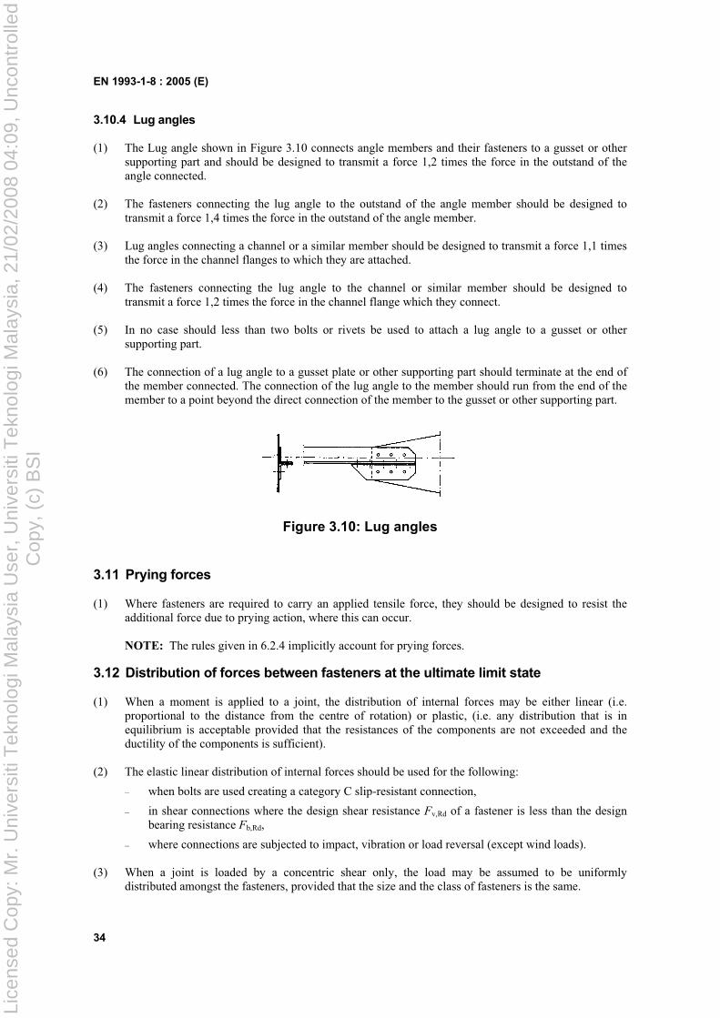
EN 1993-1-8 : 2005 (E)
34
3.10.4 Lug angles
(1) The Lug angle shown in Figure 3.10 connects angle members and their fasteners to a gusset or other supporting part and should be designed to transmit a force 1,2 times the force in the outstand of the angle connected.
(2) The fasteners connecting the lug angle to the outstand of the angle member should be designed to transmit a force 1,4 times the force in the outstand of the angle member.
(3) Lug angles connecting a channel or a similar member should be designed to transmit a force 1,1 times the force in the channel flanges to which they are attached.
(4) The fasteners connecting the lug angle to the channel or similar member should be designed to transmit a force 1,2 times the force in the channel flange which they connect.
(5) In no case should less than two bolts or rivets be used to attach a lug angle to a gusset or other supporting part.
(6) The connection of a lug angle to a gusset plate or other supporting part should terminate at the end of the member connected. The connection of the lug angle to the member should run from the end of the member to a point beyond the direct connection of the member to the gusset or other supporting part.
Figure 3.10: Lug angles
3.11 Prying forces
(1) Where fasteners are required to carry an applied tensile force, they should be designed to resist the additional force due to prying action, where this can occur.
NOTE: The rules given in 6.2.4 implicitly account for prying forces.
3.12 Distribution of forces between fasteners at the ultimate limit state
(1) When a moment is applied to a joint, the distribution of internal forces may be either linear (i.e. proportional to the distance from the centre of rotation) or plastic, (i.e. any distribution that is in equilibrium is acceptable provided that the resistances of the components are not exceeded and the ductility of the components is sufficient).
(2) The elastic linear distribution of internal forces should be used for the following:
– when bolts are used creating a category C slip-resistant connection,
– in shear connections where the design shear resistance Fv,Rd of a fastener is less than the design bearing resistance Fb,Rd,
– where connections are subjected to impact, vibration or load reversal (except wind loads).
(3) When a joint is loaded by a concentric shear only, the load may be assumed to be uniformly distributed amongst the fasteners, provided that the size and the class of fasteners is the same.
Lice
nsed
Cop
y: M
r. U
nive
rsiti
Tek
nolo
gi M
alay
sia
Use
r, U
nive
rsiti
Tek
nolo
gi M
alay
sia,
21/
02/2
008
04:0
9, U
ncon
trol
led
Cop
y, (
c) B
SI
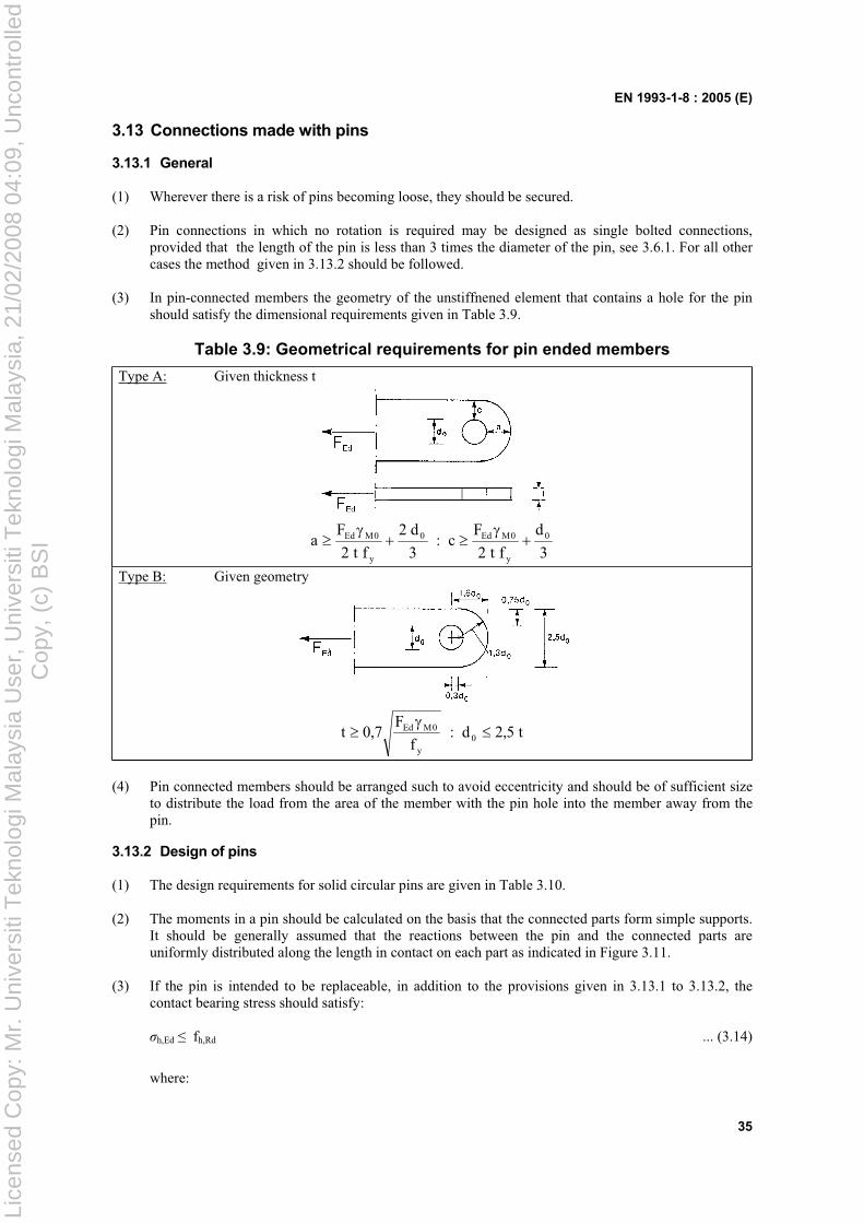
EN 1993-1-8 : 2005 (E)
35
3.13 Connections made with pins
3.13.1 General
(1) Wherever there is a risk of pins becoming loose, they should be secured.
(2) Pin connections in which no rotation is required may be designed as single bolted connections, provided that the length of the pin is less than 3 times the diameter of the pin, see 3.6.1. For all other cases the method given in 3.13.2 should be followed.
(3) In pin-connected members the geometry of the unstiffnened element that contains a hole for the pin should satisfy the dimensional requirements given in Table 3.9.
Table 3.9: Geometrical requirements for pin ended members
Type A: Given thickness t
3
d
ft2
Fc:
3
d2
ft2
Fa 0
y
0MEd0
y
0MEd
Type B: Given geometry
t5,2d:f
F7,0t 0
y
0MEd
(4) Pin connected members should be arranged such to avoid eccentricity and should be of sufficient size to distribute the load from the area of the member with the pin hole into the member away from the pin.
3.13.2 Design of pins
(1) The design requirements for solid circular pins are given in Table 3.10.
(2) The moments in a pin should be calculated on the basis that the connected parts form simple supports. It should be generally assumed that the reactions between the pin and the connected parts are uniformly distributed along the length in contact on each part as indicated in Figure 3.11.
(3) If the pin is intended to be replaceable, in addition to the provisions given in 3.13.1 to 3.13.2, the contact bearing stress should satisfy:
h,Ed fh,Rd ... (3.14)
where:
Lice
nsed
Cop
y: M
r. U
nive
rsiti
Tek
nolo
gi M
alay
sia
Use
r, U
nive
rsiti
Tek
nolo
gi M
alay
sia,
21/
02/2
008
04:0
9, U
ncon
trol
led
Cop
y, (
c) B
SI
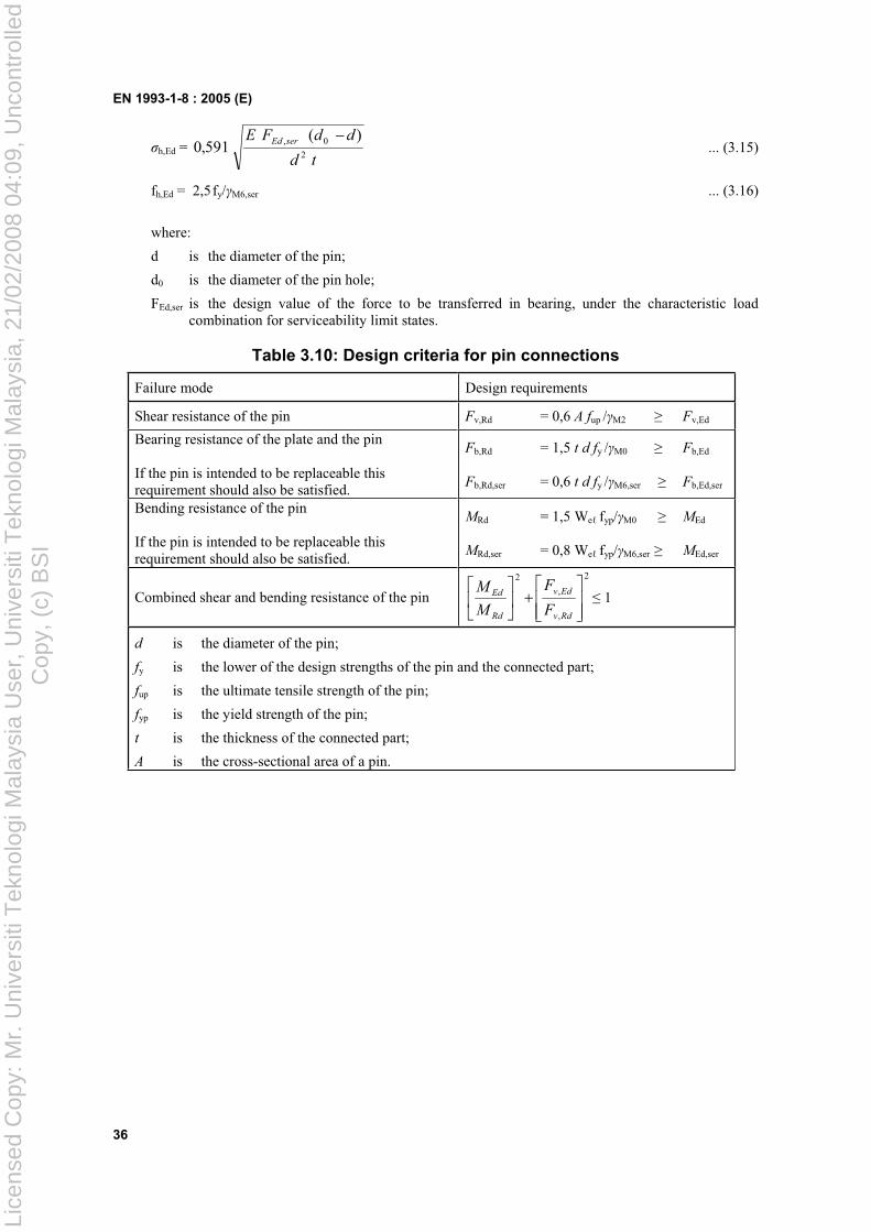
EN 1993-1-8 : 2005 (E)
36
h,Ed = td
ddFE serEd
2
0, )(591,0 ... (3.15)
fh,Ed = 2,5fy/ M6,ser ... (3.16)
where:
d is the diameter of the pin;
d0 is the diameter of the pin hole;
FEd,ser is the design value of the force to be transferred in bearing, under the characteristic load combination for serviceability limit states.
Table 3.10: Design criteria for pin connections
Failure mode Design requirements
Shear resistance of the pin Fv,Rd = 0,6 A fup / M2 Fv,Ed
Bearing resistance of the plate and the pin
If the pin is intended to be replaceable this requirement should also be satisfied.
Fb,Rd = 1,5 t d fy / M0 Fb,Ed
Fb,Rd,ser = 0,6 t d fy / M6,ser Fb,Ed,ser
Bending resistance of the pin
If the pin is intended to be replaceable this requirement should also be satisfied.
MRd = 1,5 We fyp/ M0 MEd
MRd,ser = 0,8 We fyp/ M6,ser MEd,ser
Combined shear and bending resistance of the pin
2
,
,
2
Rdv
Edv
Rd
Ed
F
F
M
M 1
d is the diameter of the pin;
fy is the lower of the design strengths of the pin and the connected part;
fup is the ultimate tensile strength of the pin;
fyp is the yield strength of the pin;
t is the thickness of the connected part;
A is the cross-sectional area of a pin.
Lice
nsed
Cop
y: M
r. U
nive
rsiti
Tek
nolo
gi M
alay
sia
Use
r, U
nive
rsiti
Tek
nolo
gi M
alay
sia,
21/
02/2
008
04:0
9, U
ncon
trol
led
Cop
y, (
c) B
SI
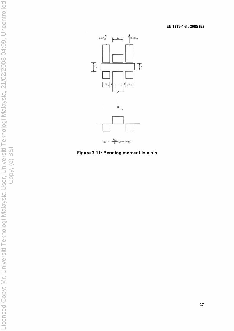
EN 1993-1-8 : 2005 (E)
37
Figure 3.11: Bending moment in a pin
Lice
nsed
Cop
y: M
r. U
nive
rsiti
Tek
nolo
gi M
alay
sia
Use
r, U
nive
rsiti
Tek
nolo
gi M
alay
sia,
21/
02/2
008
04:0
9, U
ncon
trol
led
Cop
y, (
c) B
SI
EN 1993-1-8 : 2005 (E)
38
4 Welded connections
4.1 General
(1) The provisions in this section apply to weldable structural steels conforming to EN 1993-1-1 and to material thicknesses of 4 mm and over. The provisions also apply to joints in which the mechanical properties of the weld metal are compatible with those of the parent metal, see 4.2.
For welds in thinner material reference should be made to EN 1993 part 1.3 and for welds in structural hollow sections in material thicknesses of 2,5 mm and over guidance is given section 7 of this Standard.
For stud welding reference should be made to EN 1994-1-1.
NOTE: Further guidance on stud welding can be found in EN ISO 14555 and EN ISO 13918.
(2)P Welds subject to fatigue shall also satisfy the principles given in EN 1993-1-9.
(3) Quality level C according to EN ISO 25817 is usually required, if not otherwise specified. The frequency of inspection of welds should be specified in accordance with the rules in 1.2.7 Reference Standards: Group 7. The quality level of welds should be chosen according to EN ISO 25817. For the quality level of welds used in fatigue loaded structures, see EN 1993-1-9.
(4) Lamellar tearing should be avoided.
(5) Guidance on lamellar tearing is given in EN 1993-1-10.
4.2 Welding consumables
(1) All welding consumables should conform to the relevant standards specified in 1.2.5 Reference Standards; Group 5.
(2) The specified yield strength, ultimate tensile strength, elongation at failure and minimum Charpy V-notch energy value of the filler metal, should be equivalent to, or better than that specified for the parent material.
NOTE: Generally it is safe to use electrodes that are overmatched with regard to the steel grades being used.
4.3 Geometry and dimensions
4.3.1 Type of weld
(1) This Standard covers the design of fillet welds, fillet welds all round, butt welds, plug welds and flare groove welds. Butt welds may be either full penetration butt welds or partial penetration butt welds. Both fillet welds all round and plug welds may be either in circular holes or in elongated holes.
(2) The most common types of joints and welds are illustrated in EN 12345.
4.3.2 Fillet welds
4.3.2.1 General
(1) Fillet welds may be used for connecting parts where the fusion faces form an angle of between 60° and 120°.
Lice
nsed
Cop
y: M
r. U
nive
rsiti
Tek
nolo
gi M
alay
sia
Use
r, U
nive
rsiti
Tek
nolo
gi M
alay
sia,
21/
02/2
008
04:0
9, U
ncon
trol
led
Cop
y, (
c) B
SI
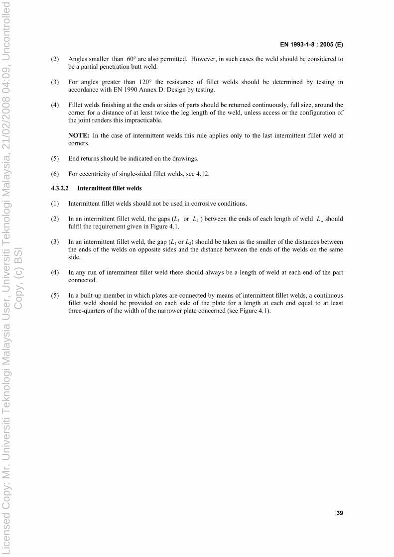
EN 1993-1-8 : 2005 (E)
39
(2) Angles smaller than 60° are also permitted. However, in such cases the weld should be considered to be a partial penetration butt weld.
(3) For angles greater than 120° the resistance of fillet welds should be determined by testing in accordance with EN 1990 Annex D: Design by testing.
(4) Fillet welds finishing at the ends or sides of parts should be returned continuously, full size, around the corner for a distance of at least twice the leg length of the weld, unless access or the configuration of the joint renders this impracticable.
NOTE: In the case of intermittent welds this rule applies only to the last intermittent fillet weld at corners.
(5) End returns should be indicated on the drawings.
(6) For eccentricity of single-sided fillet welds, see 4.12.
4.3.2.2 Intermittent fillet welds
(1) Intermittent fillet welds should not be used in corrosive conditions.
(2) In an intermittent fillet weld, the gaps (L1 or L2 ) between the ends of each length of weld Lw should fulfil the requirement given in Figure 4.1.
(3) In an intermittent fillet weld, the gap (L1 or L2) should be taken as the smaller of the distances between the ends of the welds on opposite sides and the distance between the ends of the welds on the same side.
(4) In any run of intermittent fillet weld there should always be a length of weld at each end of the part connected.
(5) In a built-up member in which plates are connected by means of intermittent fillet welds, a continuous fillet weld should be provided on each side of the plate for a length at each end equal to at least three-quarters of the width of the narrower plate concerned (see Figure 4.1).
Lice
nsed
Cop
y: M
r. U
nive
rsiti
Tek
nolo
gi M
alay
sia
Use
r, U
nive
rsiti
Tek
nolo
gi M
alay
sia,
21/
02/2
008
04:0
9, U
ncon
trol
led
Cop
y, (
c) B
SI
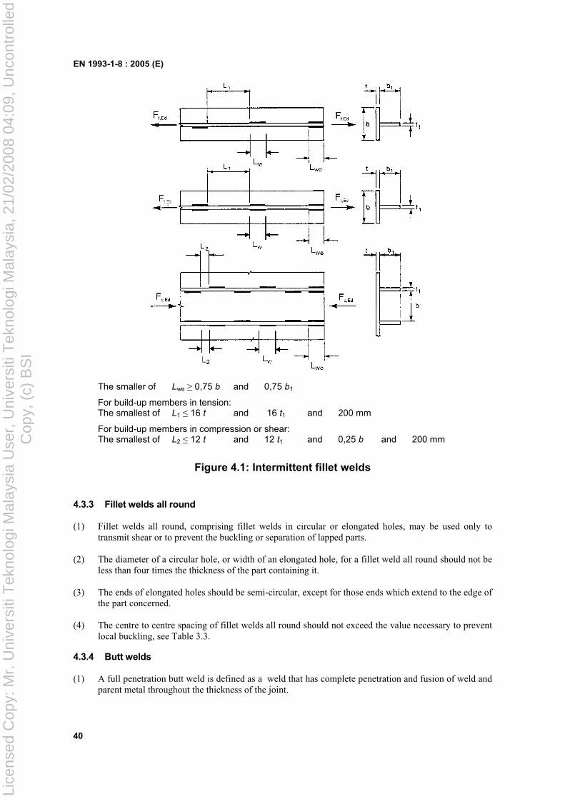
EN 1993-1-8 : 2005 (E)
40
The smaller of Lwe 0,75 b and 0,75 b1
For build-up members in tension: The smallest of L1 16 t and 16 t1 and 200 mm
For build-up members in compression or shear: The smallest of L2 12 t and 12 t1 and 0,25 b and 200 mm
Figure 4.1: Intermittent fillet welds
4.3.3 Fillet welds all round
(1) Fillet welds all round, comprising fillet welds in circular or elongated holes, may be used only to transmit shear or to prevent the buckling or separation of lapped parts.
(2) The diameter of a circular hole, or width of an elongated hole, for a fillet weld all round should not be less than four times the thickness of the part containing it.
(3) The ends of elongated holes should be semi-circular, except for those ends which extend to the edge of the part concerned.
(4) The centre to centre spacing of fillet welds all round should not exceed the value necessary to prevent local buckling, see Table 3.3.
4.3.4 Butt welds
(1) A full penetration butt weld is defined as a weld that has complete penetration and fusion of weld and parent metal throughout the thickness of the joint.
Lice
nsed
Cop
y: M
r. U
nive
rsiti
Tek
nolo
gi M
alay
sia
Use
r, U
nive
rsiti
Tek
nolo
gi M
alay
sia,
21/
02/2
008
04:0
9, U
ncon
trol
led
Cop
y, (
c) B
SI
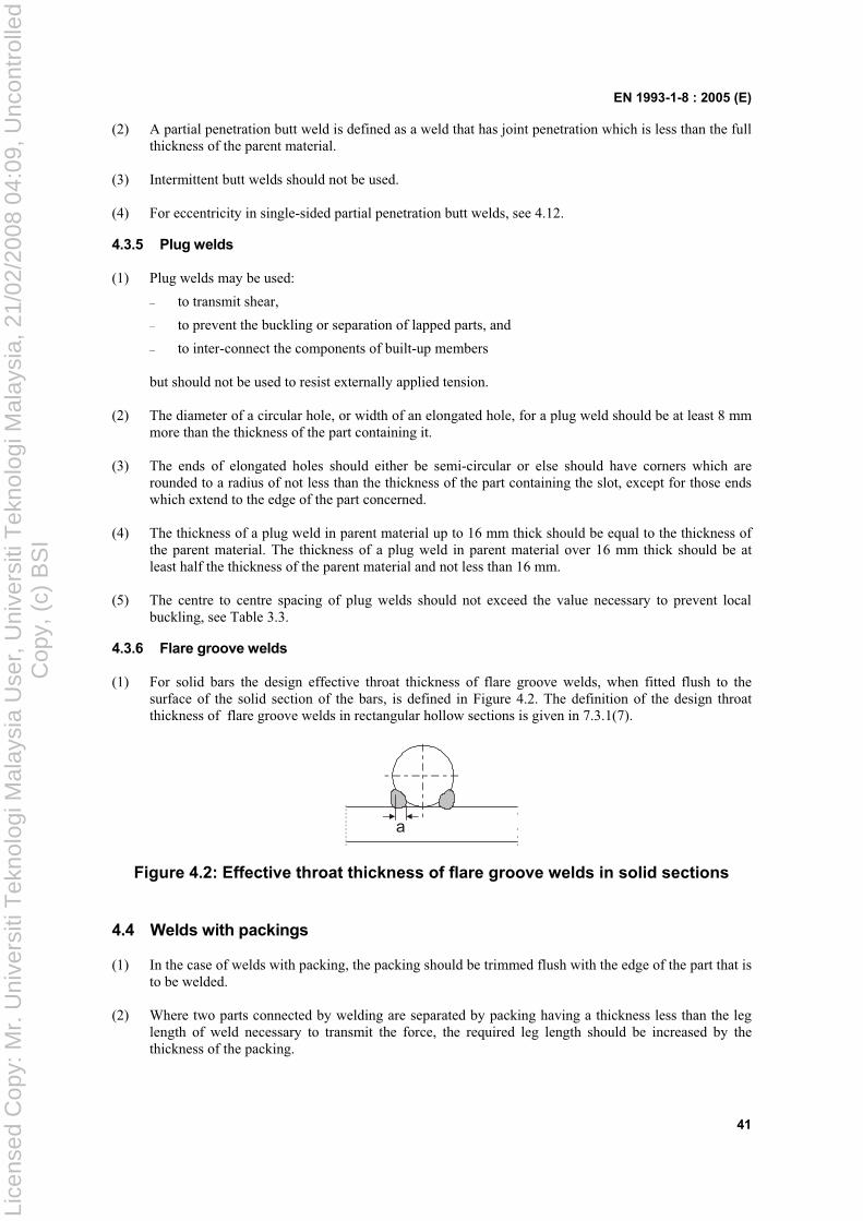
EN 1993-1-8 : 2005 (E)
41
(2) A partial penetration butt weld is defined as a weld that has joint penetration which is less than the full thickness of the parent material.
(3) Intermittent butt welds should not be used.
(4) For eccentricity in single-sided partial penetration butt welds, see 4.12.
4.3.5 Plug welds
(1) Plug welds may be used:
– to transmit shear,
– to prevent the buckling or separation of lapped parts, and
– to inter-connect the components of built-up members
but should not be used to resist externally applied tension.
(2) The diameter of a circular hole, or width of an elongated hole, for a plug weld should be at least 8 mm more than the thickness of the part containing it.
(3) The ends of elongated holes should either be semi-circular or else should have corners which are rounded to a radius of not less than the thickness of the part containing the slot, except for those ends which extend to the edge of the part concerned.
(4) The thickness of a plug weld in parent material up to 16 mm thick should be equal to the thickness of the parent material. The thickness of a plug weld in parent material over 16 mm thick should be at least half the thickness of the parent material and not less than 16 mm.
(5) The centre to centre spacing of plug welds should not exceed the value necessary to prevent local buckling, see Table 3.3.
4.3.6 Flare groove welds
(1) For solid bars the design effective throat thickness of flare groove welds, when fitted flush to the surface of the solid section of the bars, is defined in Figure 4.2. The definition of the design throat thickness of flare groove welds in rectangular hollow sections is given in 7.3.1(7).
a
Figure 4.2: Effective throat thickness of flare groove welds in solid sections
4.4 Welds with packings
(1) In the case of welds with packing, the packing should be trimmed flush with the edge of the part that is to be welded.
(2) Where two parts connected by welding are separated by packing having a thickness less than the leg length of weld necessary to transmit the force, the required leg length should be increased by the thickness of the packing.
Lice
nsed
Cop
y: M
r. U
nive
rsiti
Tek
nolo
gi M
alay
sia
Use
r, U
nive
rsiti
Tek
nolo
gi M
alay
sia,
21/
02/2
008
04:0
9, U
ncon
trol
led
Cop
y, (
c) B
SI
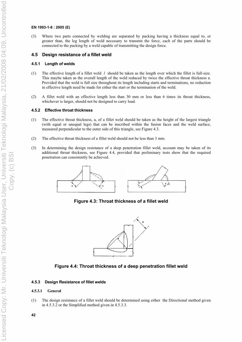
EN 1993-1-8 : 2005 (E)
42
(3) Where two parts connected by welding are separated by packing having a thickness equal to, or greater than, the leg length of weld necessary to transmit the force, each of the parts should be connected to the packing by a weld capable of transmitting the design force.
4.5 Design resistance of a fillet weld
4.5.1 Length of welds
(1) The effective length of a fillet weld l should be taken as the length over which the fillet is full-size. This maybe taken as the overall length of the weld reduced by twice the effective throat thickness a. Provided that the weld is full size throughout its length including starts and terminations, no reduction in effective length need be made for either the start or the termination of the weld.
(2) A fillet weld with an effective length less than 30 mm or less than 6 times its throat thickness, whichever is larger, should not be designed to carry load.
4.5.2 Effective throat thickness
(1) The effective throat thickness, a, of a fillet weld should be taken as the height of the largest triangle (with equal or unequal legs) that can be inscribed within the fusion faces and the weld surface, measured perpendicular to the outer side of this triangle, see Figure 4.3.
(2) The effective throat thickness of a fillet weld should not be less than 3 mm.
(3) In determining the design resistance of a deep penetration fillet weld, account may be taken of its additional throat thickness, see Figure 4.4, provided that preliminary tests show that the required penetration can consistently be achieved.
Figure 4.3: Throat thickness of a fillet weld
Figure 4.4: Throat thickness of a deep penetration fillet weld
4.5.3 Design Resistance of fillet welds
4.5.3.1 General
(1) The design resistance of a fillet weld should be determined using either the Directional method given in 4.5.3.2 or the Simplified method given in 4.5.3.3.
Lice
nsed
Cop
y: M
r. U
nive
rsiti
Tek
nolo
gi M
alay
sia
Use
r, U
nive
rsiti
Tek
nolo
gi M
alay
sia,
21/
02/2
008
04:0
9, U
ncon
trol
led
Cop
y, (
c) B
SI
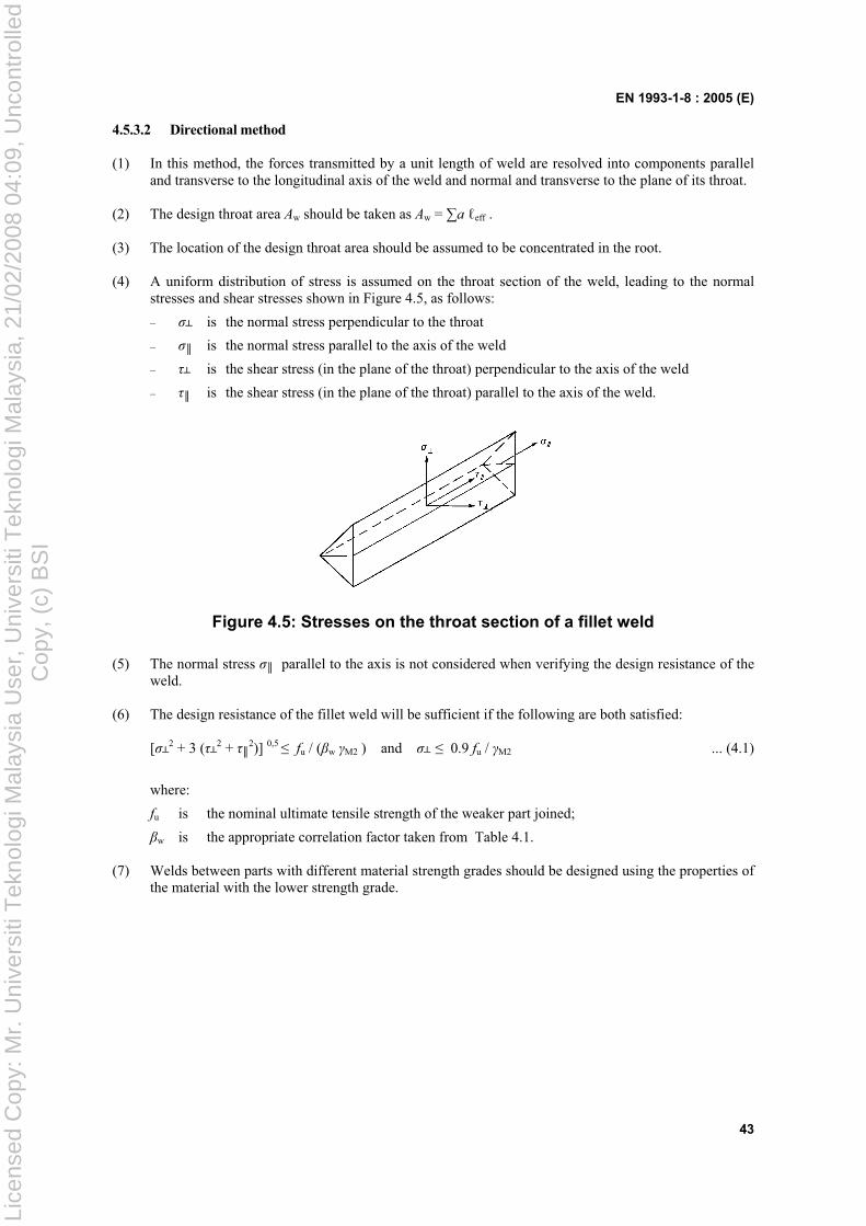
EN 1993-1-8 : 2005 (E)
43
4.5.3.2 Directional method
(1) In this method, the forces transmitted by a unit length of weld are resolved into components parallel and transverse to the longitudinal axis of the weld and normal and transverse to the plane of its throat.
(2) The design throat area Aw should be taken as Aw = a eff .
(3) The location of the design throat area should be assumed to be concentrated in the root.
(4) A uniform distribution of stress is assumed on the throat section of the weld, leading to the normal stresses and shear stresses shown in Figure 4.5, as follows:
– is the normal stress perpendicular to the throat
– is the normal stress parallel to the axis of the weld
– is the shear stress (in the plane of the throat) perpendicular to the axis of the weld
– is the shear stress (in the plane of the throat) parallel to the axis of the weld.
Figure 4.5: Stresses on the throat section of a fillet weld
(5) The normal stress parallel to the axis is not considered when verifying the design resistance of the weld.
(6) The design resistance of the fillet weld will be sufficient if the following are both satisfied:
[ 2 + 3 ( 2 + 2)] 0,5 fu / ( w M2 ) and 0.9 fu / M2 ... (4.1)
where:
fu is the nominal ultimate tensile strength of the weaker part joined;
w is the appropriate correlation factor taken from Table 4.1.
(7) Welds between parts with different material strength grades should be designed using the properties of the material with the lower strength grade.
Lice
nsed
Cop
y: M
r. U
nive
rsiti
Tek
nolo
gi M
alay
sia
Use
r, U
nive
rsiti
Tek
nolo
gi M
alay
sia,
21/
02/2
008
04:0
9, U
ncon
trol
led
Cop
y, (
c) B
SI
EN 1993-1-8 : 2005 (E)
44
Table 4.1: Correlation factor w for fillet welds
Standard and steel grade
EN 10025 EN 10210 EN 10219Correlation factor w
S 235 S 235 W
S 235 H S 235 H 0,8
S 275 S 275 N/NL
S 275 M/ML
S 275 H S 275 NH/NLH
S 275 H S 275 NH/NLH S 275 MH/MLH
0,85
S 355 S 355 N/NL
S 355 M/ML S 355 W
S 355 H S 355 NH/NLH
S 355 H S 355 NH/NLH S 355 MH/MLH
0,9
S 420 N/NL S 420 M/ML
S 420 MH/MLH 1,0
S 460 N/NL S 460 M/ML
S 460 Q/QL/QL1 S 460 NH/NLH
S 460 NH/NLH S 460 MH/MLH
1,0
4.5.3.3 Simplified method for design resistance of fillet weld
(1) Alternatively to 4.5.3.2 the design resistance of a fillet weld may be assumed to be adequate if, at every point along its length, the resultant of all the forces per unit length transmitted by the weld satisfy the following criterion:
Fw,Ed Fw,Rd ... (4.2)
where:
Fw,Ed is the design value of the weld force per unit length;
Fw,Rd is the design weld resistance per unit length.
(2) Independent of the orientation of the weld throat plane to the applied force, the design resistance per unit length Fw,Rd should be determined from:
Fw,Rd = fvw.d a ... (4.3)
where:
fvw.d is the design shear strength of the weld.
(3) The design shear strength fvw.d of the weld should be determined from:
fvw.d = 2
3/
Mw
uf ... (4.4)
where:
fu and w are defined in 4.5.3.2(6).
4.6 Design resistance of fillet welds all round
(1) The design resistance of a fillet weld all round should be determined using one of the methods given in 4.5.
Lice
nsed
Cop
y: M
r. U
nive
rsiti
Tek
nolo
gi M
alay
sia
Use
r, U
nive
rsiti
Tek
nolo
gi M
alay
sia,
21/
02/2
008
04:0
9, U
ncon
trol
led
Cop
y, (
c) B
SI
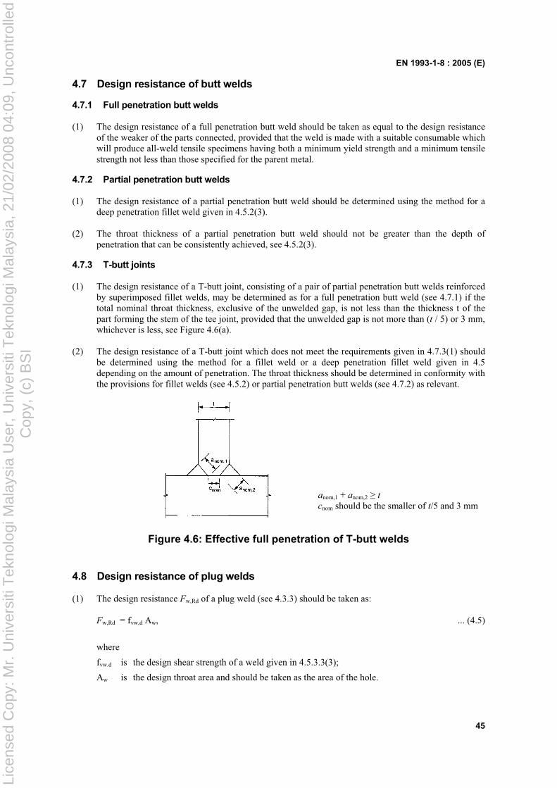
EN 1993-1-8 : 2005 (E)
45
4.7 Design resistance of butt welds
4.7.1 Full penetration butt welds
(1) The design resistance of a full penetration butt weld should be taken as equal to the design resistance of the weaker of the parts connected, provided that the weld is made with a suitable consumable which will produce all-weld tensile specimens having both a minimum yield strength and a minimum tensile strength not less than those specified for the parent metal.
4.7.2 Partial penetration butt welds
(1) The design resistance of a partial penetration butt weld should be determined using the method for a deep penetration fillet weld given in 4.5.2(3).
(2) The throat thickness of a partial penetration butt weld should not be greater than the depth of penetration that can be consistently achieved, see 4.5.2(3).
4.7.3 T-butt joints
(1) The design resistance of a T-butt joint, consisting of a pair of partial penetration butt welds reinforced by superimposed fillet welds, may be determined as for a full penetration butt weld (see 4.7.1) if the total nominal throat thickness, exclusive of the unwelded gap, is not less than the thickness t of the part forming the stem of the tee joint, provided that the unwelded gap is not more than (t / 5) or 3 mm, whichever is less, see Figure 4.6(a).
(2) The design resistance of a T-butt joint which does not meet the requirements given in 4.7.3(1) should be determined using the method for a fillet weld or a deep penetration fillet weld given in 4.5 depending on the amount of penetration. The throat thickness should be determined in conformity with the provisions for fillet welds (see 4.5.2) or partial penetration butt welds (see 4.7.2) as relevant.
anom,1 + anom,2 t
cnom should be the smaller of t/5 and 3 mm
Figure 4.6: Effective full penetration of T-butt welds
4.8 Design resistance of plug welds
(1) The design resistance Fw,Rd of a plug weld (see 4.3.3) should be taken as:
Fw,Rd = fvw,d Aw, ... (4.5)
where
fvw.d is the design shear strength of a weld given in 4.5.3.3(3);
Aw is the design throat area and should be taken as the area of the hole.
Lice
nsed
Cop
y: M
r. U
nive
rsiti
Tek
nolo
gi M
alay
sia
Use
r, U
nive
rsiti
Tek
nolo
gi M
alay
sia,
21/
02/2
008
04:0
9, U
ncon
trol
led
Cop
y, (
c) B
SI
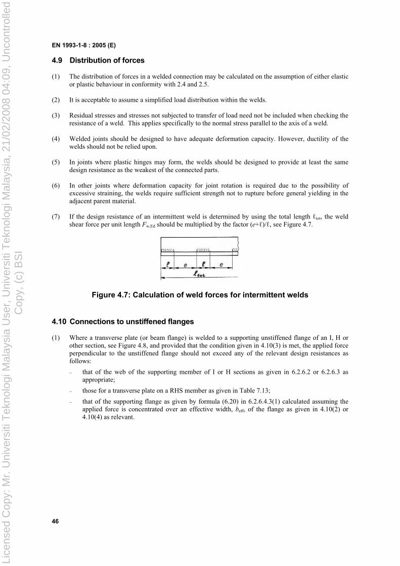
EN 1993-1-8 : 2005 (E)
46
4.9 Distribution of forces
(1) The distribution of forces in a welded connection may be calculated on the assumption of either elastic or plastic behaviour in conformity with 2.4 and 2.5.
(2) It is acceptable to assume a simplified load distribution within the welds.
(3) Residual stresses and stresses not subjected to transfer of load need not be included when checking the resistance of a weld. This applies specifically to the normal stress parallel to the axis of a weld.
(4) Welded joints should be designed to have adequate deformation capacity. However, ductility of the welds should not be relied upon.
(5) In joints where plastic hinges may form, the welds should be designed to provide at least the same design resistance as the weakest of the connected parts.
(6) In other joints where deformation capacity for joint rotation is required due to the possibility of excessive straining, the welds require sufficient strength not to rupture before general yielding in the adjacent parent material.
(7) If the design resistance of an intermittent weld is determined by using the total length tot, the weld shear force per unit length Fw,Ed should be multiplied by the factor (e+ )/ , see Figure 4.7.
Figure 4.7: Calculation of weld forces for intermittent welds
4.10 Connections to unstiffened flanges
(1) Where a transverse plate (or beam flange) is welded to a supporting unstiffened flange of an I, H or other section, see Figure 4.8, and provided that the condition given in 4.10(3) is met, the applied force perpendicular to the unstiffened flange should not exceed any of the relevant design resistances as follows:
– that of the web of the supporting member of I or H sections as given in 6.2.6.2 or 6.2.6.3 as appropriate;
– those for a transverse plate on a RHS member as given in Table 7.13;
– that of the supporting flange as given by formula (6.20) in 6.2.6.4.3(1) calculated assuming the applied force is concentrated over an effective width, beff, of the flange as given in 4.10(2) or 4.10(4) as relevant.
Lice
nsed
Cop
y: M
r. U
nive
rsiti
Tek
nolo
gi M
alay
sia
Use
r, U
nive
rsiti
Tek
nolo
gi M
alay
sia,
21/
02/2
008
04:0
9, U
ncon
trol
led
Cop
y, (
c) B
SI
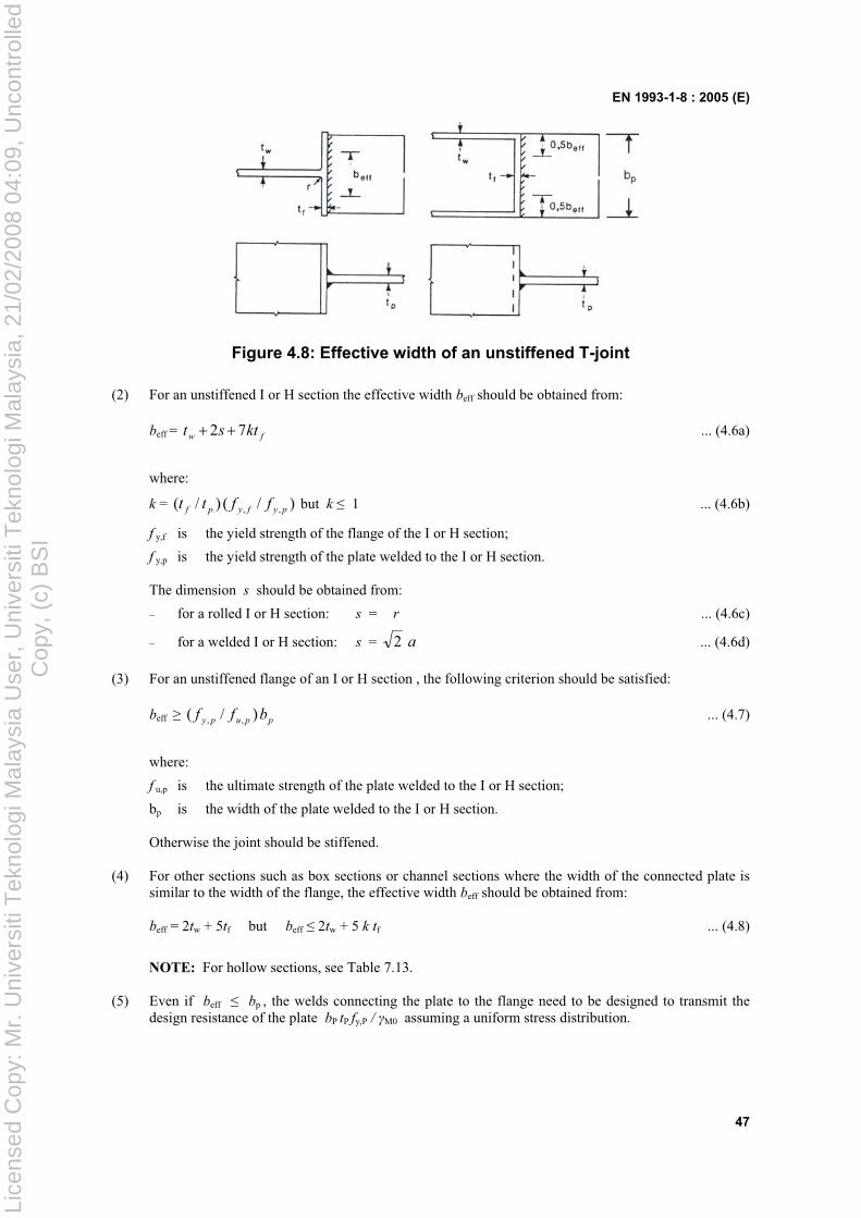
EN 1993-1-8 : 2005 (E)
47
Figure 4.8: Effective width of an unstiffened T-joint
(2) For an unstiffened I or H section the effective width beff should be obtained from:
beff = fw ktst 72 ... (4.6a)
where:
k = )/()/( ,, pyfypf fftt but k 1 ... (4.6b)
f y,f is the yield strength of the flange of the I or H section;
f y,p is the yield strength of the plate welded to the I or H section.
The dimension s should be obtained from:
– for a rolled I or H section: s = r ... (4.6c)
– for a welded I or H section: s = a2 ... (4.6d)
(3) For an unstiffened flange of an I or H section , the following criterion should be satisfied:
beff ppupy bff )/( ,, ... (4.7)
where:
f u,p is the ultimate strength of the plate welded to the I or H section;
bp is the width of the plate welded to the I or H section.
Otherwise the joint should be stiffened.
(4) For other sections such as box sections or channel sections where the width of the connected plate is similar to the width of the flange, the effective width beff should be obtained from:
beff = 2tw + 5tf but beff 2tw + 5 k tf ... (4.8)
NOTE: For hollow sections, see Table 7.13.
(5) Even if beff bp , the welds connecting the plate to the flange need to be designed to transmit the design resistance of the plate bP tP fy,P / M0 assuming a uniform stress distribution.
Lice
nsed
Cop
y: M
r. U
nive
rsiti
Tek
nolo
gi M
alay
sia
Use
r, U
nive
rsiti
Tek
nolo
gi M
alay
sia,
21/
02/2
008
04:0
9, U
ncon
trol
led
Cop
y, (
c) B
SI
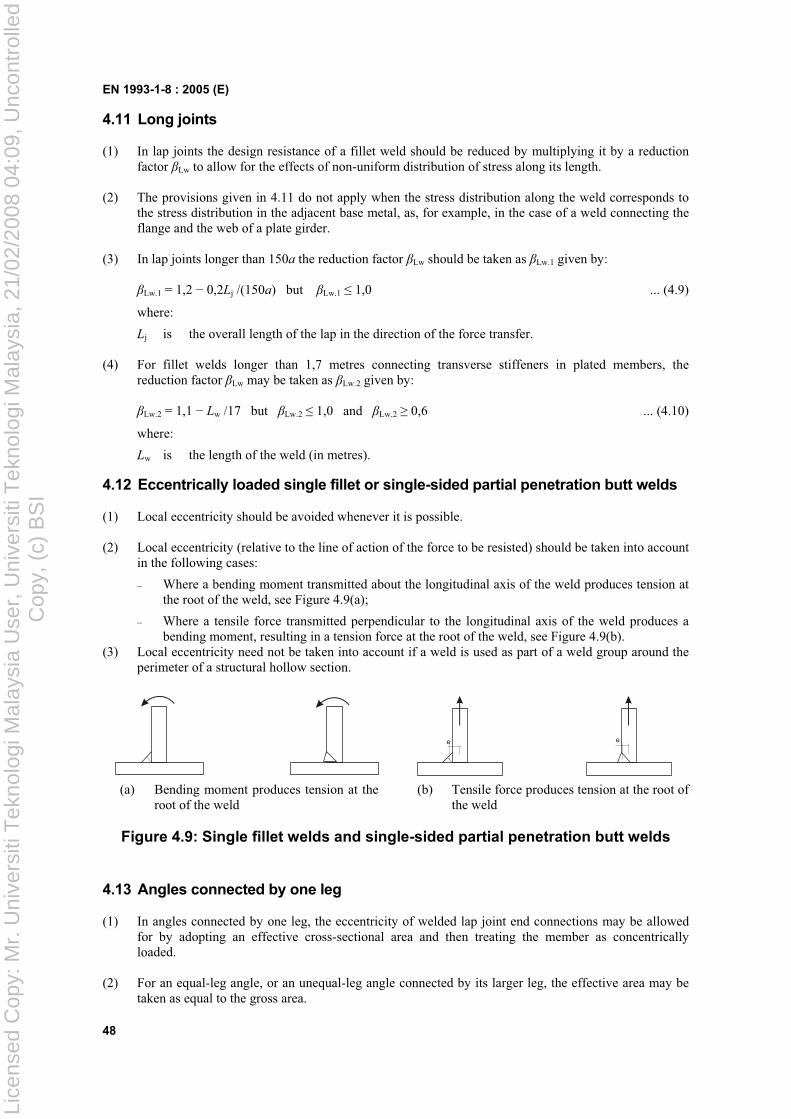
EN 1993-1-8 : 2005 (E)
48
4.11 Long joints
(1) In lap joints the design resistance of a fillet weld should be reduced by multiplying it by a reduction factor Lw to allow for the effects of non-uniform distribution of stress along its length.
(2) The provisions given in 4.11 do not apply when the stress distribution along the weld corresponds to the stress distribution in the adjacent base metal, as, for example, in the case of a weld connecting the flange and the web of a plate girder.
(3) In lap joints longer than 150a the reduction factor Lw should be taken as Lw.1 given by:
Lw.1 = 1,2 0,2Lj /(150a) but Lw.1 1,0 ... (4.9)
where:
Lj is the overall length of the lap in the direction of the force transfer.
(4) For fillet welds longer than 1,7 metres connecting transverse stiffeners in plated members, the reduction factor Lw may be taken as Lw.2 given by:
Lw.2 = 1,1 Lw /17 but Lw.2 1,0 and Lw.2 0,6 ... (4.10)
where:
Lw is the length of the weld (in metres).
4.12 Eccentrically loaded single fillet or single-sided partial penetration butt welds
(1) Local eccentricity should be avoided whenever it is possible.
(2) Local eccentricity (relative to the line of action of the force to be resisted) should be taken into account in the following cases:
– Where a bending moment transmitted about the longitudinal axis of the weld produces tension at the root of the weld, see Figure 4.9(a);
– Where a tensile force transmitted perpendicular to the longitudinal axis of the weld produces a bending moment, resulting in a tension force at the root of the weld, see Figure 4.9(b).
(3) Local eccentricity need not be taken into account if a weld is used as part of a weld group around the perimeter of a structural hollow section.
e e
(a) Bending moment produces tension at the root of the weld
(b) Tensile force produces tension at the root of the weld
Figure 4.9: Single fillet welds and single-sided partial penetration butt welds
4.13 Angles connected by one leg
(1) In angles connected by one leg, the eccentricity of welded lap joint end connections may be allowed for by adopting an effective cross-sectional area and then treating the member as concentrically loaded.
(2) For an equal-leg angle, or an unequal-leg angle connected by its larger leg, the effective area may be taken as equal to the gross area.
Lice
nsed
Cop
y: M
r. U
nive
rsiti
Tek
nolo
gi M
alay
sia
Use
r, U
nive
rsiti
Tek
nolo
gi M
alay
sia,
21/
02/2
008
04:0
9, U
ncon
trol
led
Cop
y, (
c) B
SI
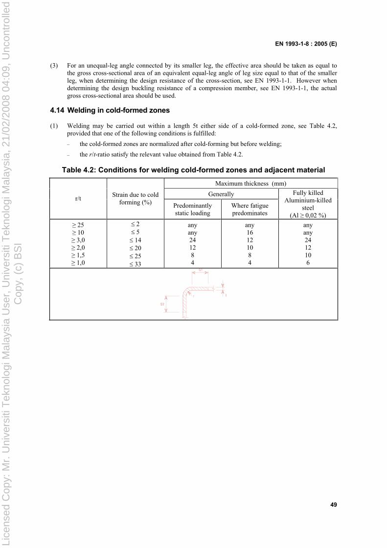
EN 1993-1-8 : 2005 (E)
49
(3) For an unequal-leg angle connected by its smaller leg, the effective area should be taken as equal to the gross cross-sectional area of an equivalent equal-leg angle of leg size equal to that of the smaller leg, when determining the design resistance of the cross-section, see EN 1993-1-1. However when determining the design buckling resistance of a compression member, see EN 1993-1-1, the actual gross cross-sectional area should be used.
4.14 Welding in cold-formed zones
(1) Welding may be carried out within a length 5t either side of a cold-formed zone, see Table 4.2, provided that one of the following conditions is fulfilled:
– the cold-formed zones are normalized after cold-forming but before welding;
– the r/t-ratio satisfy the relevant value obtained from Table 4.2.
Table 4.2: Conditions for welding cold-formed zones and adjacent material
Maximum thickness (mm)
Generallyr/t
Strain due to cold forming (%) Predominantly
static loadingWhere fatigue predominates
Fully killed Aluminium-killed
steel(Al 0,02 %)
25 10 3,0 2,0 1,5 1,0
2 5 14 20 25 33
any any 241284
any 16 12 10 84
any any 24 12 10 6
Lice
nsed
Cop
y: M
r. U
nive
rsiti
Tek
nolo
gi M
alay
sia
Use
r, U
nive
rsiti
Tek
nolo
gi M
alay
sia,
21/
02/2
008
04:0
9, U
ncon
trol
led
Cop
y, (
c) B
SI
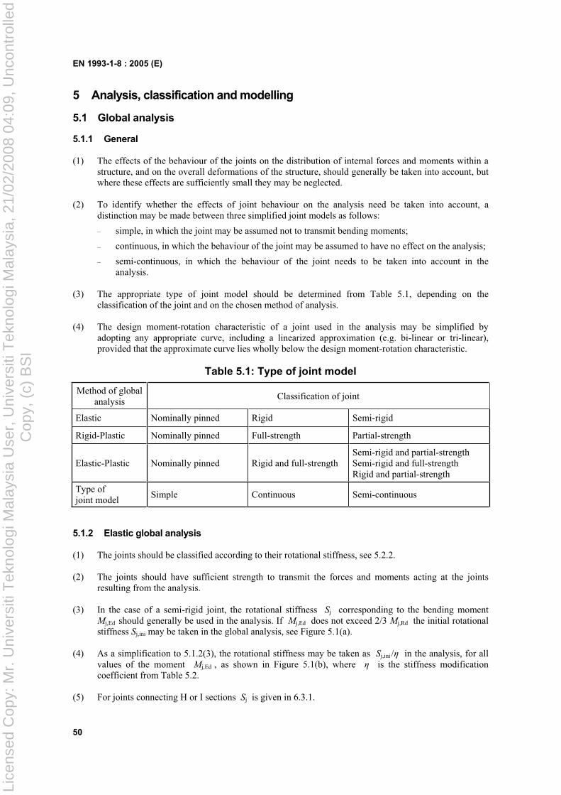
EN 1993-1-8 : 2005 (E)
50
5 Analysis, classification and modelling
5.1 Global analysis
5.1.1 General
(1) The effects of the behaviour of the joints on the distribution of internal forces and moments within a structure, and on the overall deformations of the structure, should generally be taken into account, but where these effects are sufficiently small they may be neglected.
(2) To identify whether the effects of joint behaviour on the analysis need be taken into account, a distinction may be made between three simplified joint models as follows:
– simple, in which the joint may be assumed not to transmit bending moments;
– continuous, in which the behaviour of the joint may be assumed to have no effect on the analysis;
– semi-continuous, in which the behaviour of the joint needs to be taken into account in the analysis.
(3) The appropriate type of joint model should be determined from Table 5.1, depending on the classification of the joint and on the chosen method of analysis.
(4) The design moment-rotation characteristic of a joint used in the analysis may be simplified by adopting any appropriate curve, including a linearized approximation (e.g. bi-linear or tri-linear), provided that the approximate curve lies wholly below the design moment-rotation characteristic.
Table 5.1: Type of joint model
Method of global analysis
Classification of joint
Elastic Nominally pinned Rigid Semi-rigid
Rigid-Plastic Nominally pinned Full-strength Partial-strength
Elastic-Plastic Nominally pinned Rigid and full-strengthSemi-rigid and partial-strength Semi-rigid and full-strength Rigid and partial-strength
Type of joint model
Simple Continuous Semi-continuous
5.1.2 Elastic global analysis
(1) The joints should be classified according to their rotational stiffness, see 5.2.2.
(2) The joints should have sufficient strength to transmit the forces and moments acting at the joints resulting from the analysis.
(3) In the case of a semi-rigid joint, the rotational stiffness Sj corresponding to the bending moment Mj,Ed should generally be used in the analysis. If Mj,Ed does not exceed 2/3 Mj,Rd the initial rotational stiffness Sj,ini may be taken in the global analysis, see Figure 5.1(a).
(4) As a simplification to 5.1.2(3), the rotational stiffness may be taken as Sj,ini / in the analysis, for all values of the moment Mj,Ed , as shown in Figure 5.1(b), where is the stiffness modification coefficient from Table 5.2.
(5) For joints connecting H or I sections Sj is given in 6.3.1.
Lice
nsed
Cop
y: M
r. U
nive
rsiti
Tek
nolo
gi M
alay
sia
Use
r, U
nive
rsiti
Tek
nolo
gi M
alay
sia,
21/
02/2
008
04:0
9, U
ncon
trol
led
Cop
y, (
c) B
SI
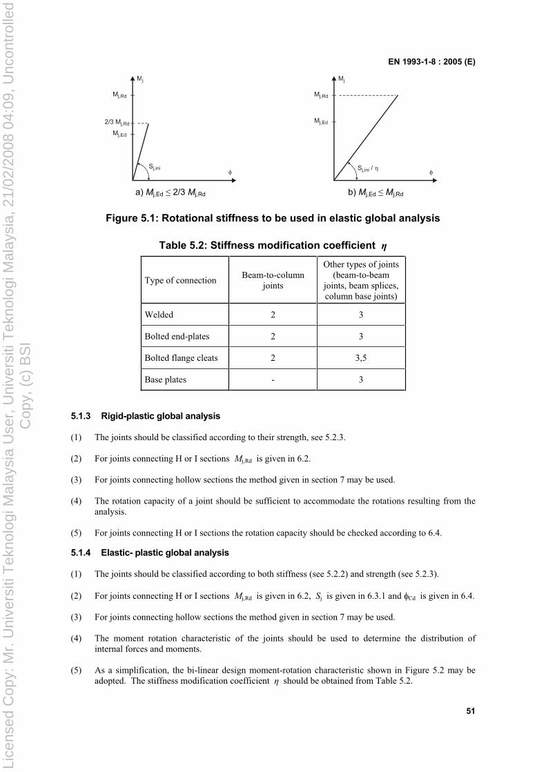
EN 1993-1-8 : 2005 (E)
51
Mj
Mj,Ed
Mj,Rd
2/3 Mj,Rd
Sj,ini
Mj
Mj,Ed
Mj,Rd
Sj,ini /
a) Mj,Ed 2/3 Mj,Rd b) Mj,Ed Mj,Rd
Figure 5.1: Rotational stiffness to be used in elastic global analysis
Table 5.2: Stiffness modification coefficient
Type of connectionBeam-to-column
joints
Other types of joints (beam-to-beam
joints, beam splices, column base joints)
Welded 2 3
Bolted end-plates 2 3
Bolted flange cleats 2 3,5
Base plates - 3
5.1.3 Rigid-plastic global analysis
(1) The joints should be classified according to their strength, see 5.2.3.
(2) For joints connecting H or I sections Mj,Rd is given in 6.2.
(3) For joints connecting hollow sections the method given in section 7 may be used.
(4) The rotation capacity of a joint should be sufficient to accommodate the rotations resulting from the analysis.
(5) For joints connecting H or I sections the rotation capacity should be checked according to 6.4.
5.1.4 Elastic- plastic global analysis
(1) The joints should be classified according to both stiffness (see 5.2.2) and strength (see 5.2.3).
(2) For joints connecting H or I sections Mj,Rd is given in 6.2, Sj is given in 6.3.1 and Cd is given in 6.4.
(3) For joints connecting hollow sections the method given in section 7 may be used.
(4) The moment rotation characteristic of the joints should be used to determine the distribution of internal forces and moments.
(5) As a simplification, the bi-linear design moment-rotation characteristic shown in Figure 5.2 may be adopted. The stiffness modification coefficient should be obtained from Table 5.2.
Lice
nsed
Cop
y: M
r. U
nive
rsiti
Tek
nolo
gi M
alay
sia
Use
r, U
nive
rsiti
Tek
nolo
gi M
alay
sia,
21/
02/2
008
04:0
9, U
ncon
trol
led
Cop
y, (
c) B
SI
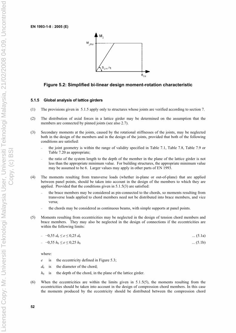
EN 1993-1-8 : 2005 (E)
52
Figure 5.2: Simplified bi-linear design moment-rotation characteristic
5.1.5 Global analysis of lattice girders
(1) The provisions given in 5.1.5 apply only to structures whose joints are verified according to section 7.
(2) The distribution of axial forces in a lattice girder may be determined on the assumption that the members are connected by pinned joints (see also 2.7).
(3) Secondary moments at the joints, caused by the rotational stiffnesses of the joints, may be neglected both in the design of the members and in the design of the joints, provided that both of the following conditions are satisfied:
– the joint geometry is within the range of validity specified in Table 7.1, Table 7.8, Table 7.9 or Table 7.20 as appropriate;
– the ratio of the system length to the depth of the member in the plane of the lattice girder is not less than the appropriate minimum value. For building structures, the appropriate minimum value may be assumed to be 6. Larger values may apply in other parts of EN 1993.
(4) The moments resulting from transverse loads (whether in-plane or out-of-plane) that are applied between panel points, should be taken into account in the design of the members to which they are applied. Provided that the conditions given in 5.1.5(3) are satisfied:
– the brace members may be considered as pin-connected to the chords, so moments resulting from transverse loads applied to chord members need not be distributed into brace members, and vice versa;
– the chords may be considered as continuous beams, with simple supports at panel points.
(5) Moments resulting from eccentricities may be neglected in the design of tension chord members and brace members. They may also be neglected in the design of connections if the eccentricities are within the following limits:
– 0,55 d0 e 0,25 d0 ... (5.1a)
– 0,55 h0 e 0,25 h0 ... (5.1b)
where:
e is the eccentricity defined in Figure 5.3;
d0 is the diameter of the chord;
h0 is the depth of the chord, in the plane of the lattice girder.
(6) When the eccentricities are within the limits given in 5.1.5(5), the moments resulting from the eccentricities should be taken into account in the design of compression chord members. In this case the moments produced by the eccentricity should be distributed between the compression chord
Lice
nsed
Cop
y: M
r. U
nive
rsiti
Tek
nolo
gi M
alay
sia
Use
r, U
nive
rsiti
Tek
nolo
gi M
alay
sia,
21/
02/2
008
04:0
9, U
ncon
trol
led
Cop
y, (
c) B
SI
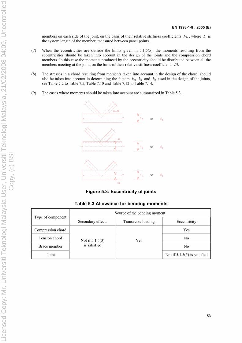
EN 1993-1-8 : 2005 (E)
53
members on each side of the joint, on the basis of their relative stiffness coefficients I/L , where L is the system length of the member, measured between panel points.
(7) When the eccentricities are outside the limits given in 5.1.5(5), the moments resulting from the eccentricities should be taken into account in the design of the joints and the compression chord members. In this case the moments produced by the eccentricity should be distributed between all the members meeting at the joint, on the basis of their relative stiffness coefficients I/L .
(8) The stresses in a chord resulting from moments taken into account in the design of the chord, should also be taken into account in determining the factors km , kn and kp used in the design of the joints, see Table 7.2 to Table 7.5, Table 7.10 and Table 7.12 to Table 7.14.
(9) The cases where moments should be taken into account are summarized in Table 5.3.
or
or
or
Figure 5.3: Eccentricity of joints
Table 5.3 Allowance for bending moments
Source of the bending momentType of component
Secondary effects Transverse loading Eccentricity
Compression chord Yes
Tension chord No
Brace member No
Joint
Not if 5.1.5(3) is satisfied
Yes
Not if 5.1.5(5) is satisfied
Lice
nsed
Cop
y: M
r. U
nive
rsiti
Tek
nolo
gi M
alay
sia
Use
r, U
nive
rsiti
Tek
nolo
gi M
alay
sia,
21/
02/2
008
04:0
9, U
ncon
trol
led
Cop
y, (
c) B
SI
EN 1993-1-8 : 2005 (E)
54
5.2 Classification of joints
5.2.1 General
(1) The details of all joints should fulfil the assumptions made in the relevant design method, without adversely affecting any other part of the structure.
(2) Joints may be classified by their stiffness (see 5.2.2) and by their strength (see 5.2.3).
NOTE: The National Annex may give additional information on the classification of joints by their stiffness and strength to that given in 5.2.2.1(2).
5.2.2 Classification by stiffness
5.2.2.1 General
(1) A joint may be classified as rigid, nominally pinned or semi-rigid according to its rotational stiffness, by comparing its initial rotational stiffness Sj,ini with the classification boundaries given in 5.2.2.5.
NOTE: Rules for the determination of Sj,ini for joints connecting H or I sections are given in 6.3.1. Rules for the determination of Sj,ini for joints connecting hollow sections are not given in this Standard.
(2) A joint may be classified on the basis of experimental evidence, experience of previous satisfactory performance in similar cases or by calculations based on test evidence.
5.2.2.2 Nominally pinned joints
(1) A nominally pinned joint should be capable of transmitting the internal forces, without developing significant moments which might adversely affect the members or the structure as a whole.
(2) A nominally pinned joint should be capable of accepting the resulting rotations under the design loads.
5.2.2.3 Rigid joints
(1) Joints classified as rigid may be assumed to have sufficient rotational stiffness to justify analysis based on full continuity.
5.2.2.4 Semi-rigid joints
(1) A joint which does not meet the criteria for a rigid joint or a nominally pinned joint should be classified as a semi-rigid joint.
NOTE: Semi-rigid joints provide a predictable degree of interaction between members, based on the design moment-rotation characteristics of the joints.
(2) Semi-rigid joints should be capable of transmitting the internal forces and moments.
5.2.2.5 Classification boundaries
(1) Classification boundaries for joints other than column bases are given in 5.2.2.1(1) and Figure 5.4.
Lice
nsed
Cop
y: M
r. U
nive
rsiti
Tek
nolo
gi M
alay
sia
Use
r, U
nive
rsiti
Tek
nolo
gi M
alay
sia,
21/
02/2
008
04:0
9, U
ncon
trol
led
Cop
y, (
c) B
SI
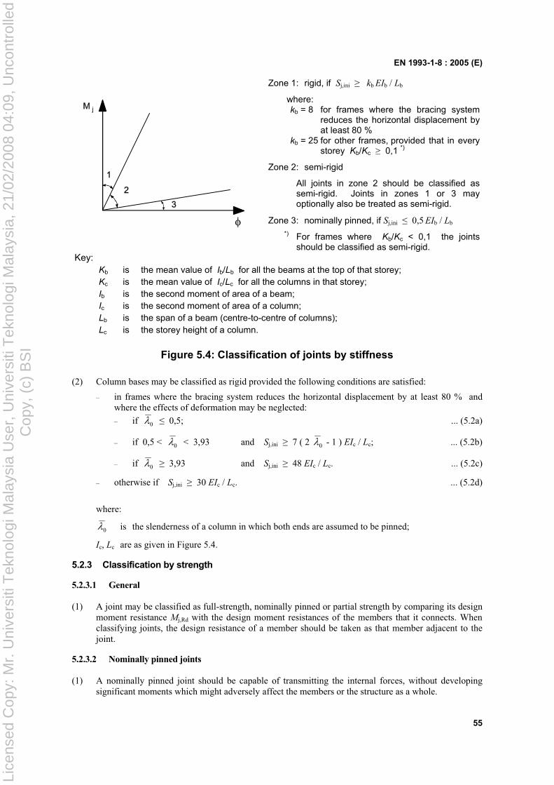
EN 1993-1-8 : 2005 (E)
55
Zone 1: rigid, if Sj,ini kb EIb / Lb
where: kb = 8 for frames where the bracing system
reduces the horizontal displacement by at least 80 %
kb = 25 for other frames, provided that in every storey Kb/Kc 0,1 *)
Zone 2: semi-rigid
All joints in zone 2 should be classified as semi-rigid. Joints in zones 1 or 3 may optionally also be treated as semi-rigid.
Zone 3: nominally pinned, if Sj,ini 0,5 EIb / Lb
*) For frames where Kb/Kc < 0,1 the joints should be classified as semi-rigid.
Key:Kb is the mean value of Ib/Lb for all the beams at the top of that storey; Kc is the mean value of Ic/Lc for all the columns in that storey; Ib is the second moment of area of a beam; Ic is the second moment of area of a column; Lb is the span of a beam (centre-to-centre of columns); Lc is the storey height of a column.
Figure 5.4: Classification of joints by stiffness
(2) Column bases may be classified as rigid provided the following conditions are satisfied:
– in frames where the bracing system reduces the horizontal displacement by at least 80 % and where the effects of deformation may be neglected:
– if 0 0,5; ... (5.2a)
– if 0,5 < 0 < 3,93 and Sj,ini 7 ( 2 0 - 1 ) EIc / Lc; ... (5.2b)
– if 0 3,93 and Sj,ini 48 EIc / Lc. ... (5.2c)
– otherwise if Sj,ini 30 EIc / Lc. ... (5.2d)
where:
0 is the slenderness of a column in which both ends are assumed to be pinned;
Ic, Lc are as given in Figure 5.4.
5.2.3 Classification by strength
5.2.3.1 General
(1) A joint may be classified as full-strength, nominally pinned or partial strength by comparing its design moment resistance Mj,Rd with the design moment resistances of the members that it connects. When classifying joints, the design resistance of a member should be taken as that member adjacent to the joint.
5.2.3.2 Nominally pinned joints
(1) A nominally pinned joint should be capable of transmitting the internal forces, without developing significant moments which might adversely affect the members or the structure as a whole.
Lice
nsed
Cop
y: M
r. U
nive
rsiti
Tek
nolo
gi M
alay
sia
Use
r, U
nive
rsiti
Tek
nolo
gi M
alay
sia,
21/
02/2
008
04:0
9, U
ncon
trol
led
Cop
y, (
c) B
SI
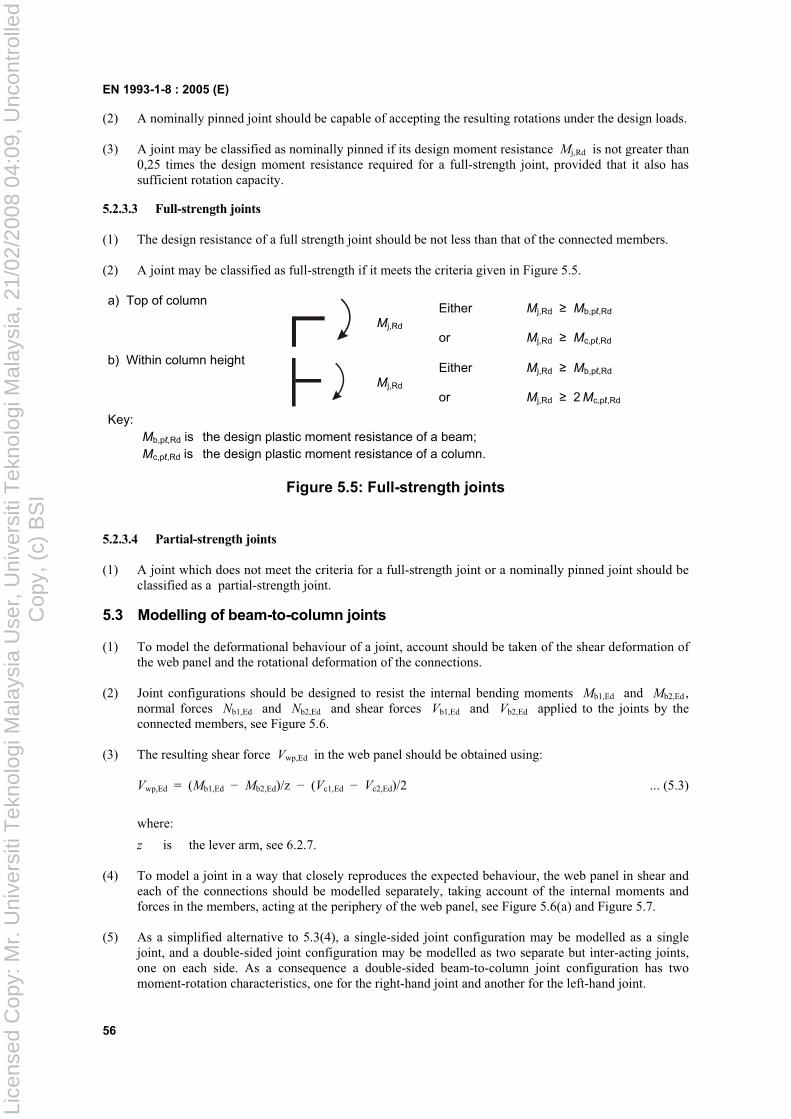
EN 1993-1-8 : 2005 (E)
56
(2) A nominally pinned joint should be capable of accepting the resulting rotations under the design loads.
(3) A joint may be classified as nominally pinned if its design moment resistance Mj,Rd is not greater than 0,25 times the design moment resistance required for a full-strength joint, provided that it also has sufficient rotation capacity.
5.2.3.3 Full-strength joints
(1) The design resistance of a full strength joint should be not less than that of the connected members.
(2) A joint may be classified as full-strength if it meets the criteria given in Figure 5.5.
a) Top of column
Mj,Rd
Either Mj,Rd Mb,p ,Rd
or Mj,Rd Mc,p ,Rd
b) Within column height
Mj,Rd
Either Mj,Rd Mb,p ,Rd
or Mj,Rd 2 Mc,p ,Rd
Key:Mb,p ,Rd is the design plastic moment resistance of a beam; Mc,p ,Rd is the design plastic moment resistance of a column.
Figure 5.5: Full-strength joints
5.2.3.4 Partial-strength joints
(1) A joint which does not meet the criteria for a full-strength joint or a nominally pinned joint should be classified as a partial-strength joint.
5.3 Modelling of beam-to-column joints
(1) To model the deformational behaviour of a joint, account should be taken of the shear deformation of the web panel and the rotational deformation of the connections.
(2) Joint configurations should be designed to resist the internal bending moments Mb1,Ed and Mb2,Ed ,normal forces Nb1,Ed and Nb2,Ed and shear forces Vb1,Ed and Vb2,Ed applied to the joints by the connected members, see Figure 5.6.
(3) The resulting shear force Vwp,Ed in the web panel should be obtained using:
Vwp,Ed = (Mb1,Ed Mb2,Ed)/z (Vc1,Ed Vc2,Ed)/2 ... (5.3)
where:
z is the lever arm, see 6.2.7.
(4) To model a joint in a way that closely reproduces the expected behaviour, the web panel in shear and each of the connections should be modelled separately, taking account of the internal moments and forces in the members, acting at the periphery of the web panel, see Figure 5.6(a) and Figure 5.7.
(5) As a simplified alternative to 5.3(4), a single-sided joint configuration may be modelled as a single joint, and a double-sided joint configuration may be modelled as two separate but inter-acting joints, one on each side. As a consequence a double-sided beam-to-column joint configuration has two moment-rotation characteristics, one for the right-hand joint and another for the left-hand joint.
Lice
nsed
Cop
y: M
r. U
nive
rsiti
Tek
nolo
gi M
alay
sia
Use
r, U
nive
rsiti
Tek
nolo
gi M
alay
sia,
21/
02/2
008
04:0
9, U
ncon
trol
led
Cop
y, (
c) B
SI
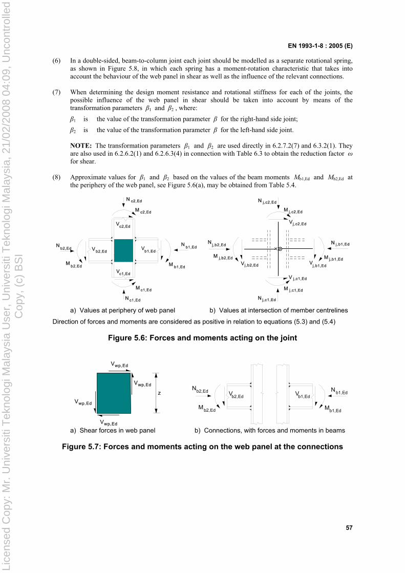
EN 1993-1-8 : 2005 (E)
57
(6) In a double-sided, beam-to-column joint each joint should be modelled as a separate rotational spring, as shown in Figure 5.8, in which each spring has a moment-rotation characteristic that takes into account the behaviour of the web panel in shear as well as the influence of the relevant connections.
(7) When determining the design moment resistance and rotational stiffness for each of the joints, the possible influence of the web panel in shear should be taken into account by means of the transformation parameters 1 and 2 , where:
1 is the value of the transformation parameter for the right-hand side joint;
2 is the value of the transformation parameter for the left-hand side joint.
NOTE: The transformation parameters 1 and 2 are used directly in 6.2.7.2(7) and 6.3.2(1). They are also used in 6.2.6.2(1) and 6.2.6.3(4) in connection with Table 6.3 to obtain the reduction factor for shear.
(8) Approximate values for 1 and 2 based on the values of the beam moments Mb1,Ed and Mb2,Ed at the periphery of the web panel, see Figure 5.6(a), may be obtained from Table 5.4.
a) Values at periphery of web panel b) Values at intersection of member centrelines
Direction of forces and moments are considered as positive in relation to equations (5.3) and (5.4)
Figure 5.6: Forces and moments acting on the joint
Mb2,Ed
Nb2,Ed Vb2,Ed
Vb1,Ed
Mb1,Ed
Nb1,Ed
a) Shear forces in web panel b) Connections, with forces and moments in beams
Figure 5.7: Forces and moments acting on the web panel at the connections
Lice
nsed
Cop
y: M
r. U
nive
rsiti
Tek
nolo
gi M
alay
sia
Use
r, U
nive
rsiti
Tek
nolo
gi M
alay
sia,
21/
02/2
008
04:0
9, U
ncon
trol
led
Cop
y, (
c) B
SI
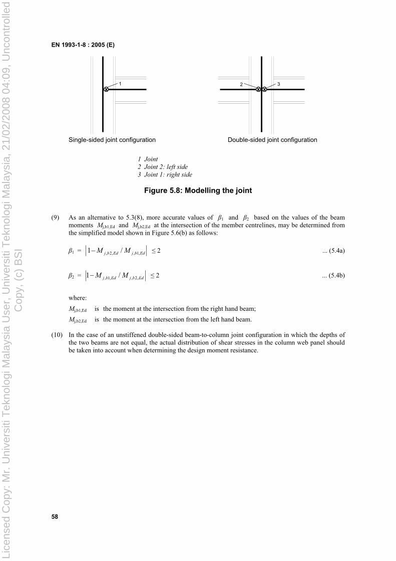
EN 1993-1-8 : 2005 (E)
58
x xx3 21
Single-sided joint configuration Double-sided joint configuration
1 Joint
2 Joint 2: left side
3 Joint 1: right side
Figure 5.8: Modelling the joint
(9) As an alternative to 5.3(8), more accurate values of 1 and 2 based on the values of the beam moments Mj,b1,Ed and Mj,b2,Ed at the intersection of the member centrelines, may be determined from the simplified model shown in Figure 5.6(b) as follows:
1 = EdbjEdbj MM ,1,,2, /1 2 ... (5.4a)
2 = EdbjEdbj MM ,2,,1, /1 2 ... (5.4b)
where:
Mj,b1,Ed is the moment at the intersection from the right hand beam;
Mj,b2,Ed is the moment at the intersection from the left hand beam.
(10) In the case of an unstiffened double-sided beam-to-column joint configuration in which the depths of the two beams are not equal, the actual distribution of shear stresses in the column web panel should be taken into account when determining the design moment resistance.
Lice
nsed
Cop
y: M
r. U
nive
rsiti
Tek
nolo
gi M
alay
sia
Use
r, U
nive
rsiti
Tek
nolo
gi M
alay
sia,
21/
02/2
008
04:0
9, U
ncon
trol
led
Cop
y, (
c) B
SI
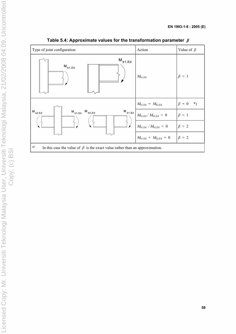
EN 1993-1-8 : 2005 (E)
59
Table 5.4: Approximate values for the transformation parameter
Type of joint configuration Action Value of
Mb1,Ed 1
Mb1,Ed = Mb2,Ed = 0 *)
Mb1,Ed / Mb2,Ed > 0 1
Mb1,Ed / Mb2,Ed < 0 2
Mb1,Ed + Mb2,Ed = 0 2
*) In this case the value of is the exact value rather than an approximation.
Lice
nsed
Cop
y: M
r. U
nive
rsiti
Tek
nolo
gi M
alay
sia
Use
r, U
nive
rsiti
Tek
nolo
gi M
alay
sia,
21/
02/2
008
04:0
9, U
ncon
trol
led
Cop
y, (
c) B
SI
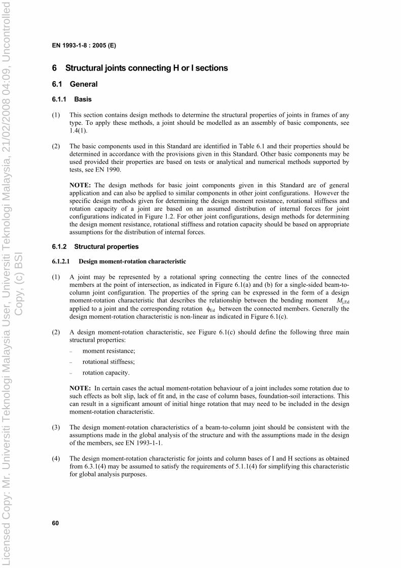
EN 1993-1-8 : 2005 (E)
60
6 Structural joints connecting H or I sections
6.1 General
6.1.1 Basis
(1) This section contains design methods to determine the structural properties of joints in frames of any type. To apply these methods, a joint should be modelled as an assembly of basic components, see 1.4(1).
(2) The basic components used in this Standard are identified in Table 6.1 and their properties should be determined in accordance with the provisions given in this Standard. Other basic components may be used provided their properties are based on tests or analytical and numerical methods supported by tests, see EN 1990.
NOTE: The design methods for basic joint components given in this Standard are of general application and can also be applied to similar components in other joint configurations. However the specific design methods given for determining the design moment resistance, rotational stiffness and rotation capacity of a joint are based on an assumed distribution of internal forces for joint configurations indicated in Figure 1.2. For other joint configurations, design methods for determining the design moment resistance, rotational stiffness and rotation capacity should be based on appropriate assumptions for the distribution of internal forces.
6.1.2 Structural properties
6.1.2.1 Design moment-rotation characteristic
(1) A joint may be represented by a rotational spring connecting the centre lines of the connected members at the point of intersection, as indicated in Figure 6.1(a) and (b) for a single-sided beam-to-column joint configuration. The properties of the spring can be expressed in the form of a design moment-rotation characteristic that describes the relationship between the bending moment Mj,Ed
applied to a joint and the corresponding rotation Ed between the connected members. Generally the design moment-rotation characteristic is non-linear as indicated in Figure 6.1(c).
(2) A design moment-rotation characteristic, see Figure 6.1(c) should define the following three main structural properties:
– moment resistance;
– rotational stiffness;
– rotation capacity.
NOTE: In certain cases the actual moment-rotation behaviour of a joint includes some rotation due to such effects as bolt slip, lack of fit and, in the case of column bases, foundation-soil interactions. This can result in a significant amount of initial hinge rotation that may need to be included in the design moment-rotation characteristic.
(3) The design moment-rotation characteristics of a beam-to-column joint should be consistent with the assumptions made in the global analysis of the structure and with the assumptions made in the design of the members, see EN 1993-1-1.
(4) The design moment-rotation characteristic for joints and column bases of I and H sections as obtained from 6.3.1(4) may be assumed to satisfy the requirements of 5.1.1(4) for simplifying this characteristic for global analysis purposes.
Lice
nsed
Cop
y: M
r. U
nive
rsiti
Tek
nolo
gi M
alay
sia
Use
r, U
nive
rsiti
Tek
nolo
gi M
alay
sia,
21/
02/2
008
04:0
9, U
ncon
trol
led
Cop
y, (
c) B
SI
EN 1993-1-8 : 2005 (E)
61
6.1.2.2 Design Moment resistance
(1) The design moment resistance Mj,Rd, which is equal to the maximum moment of the design moment-rotation characteristic, see Figure 6.1(c), should be taken as that given by 6.1.3(4)
6.1.2.3 Rotational stiffness
(1) The rotational stiffness Sj, which is the secant stiffness as indicated in Figure 6.1(c), should be taken as that given by 6.3.1(4). For a design moment-rotation characteristic this definition of Sj applies up to the rotation Xd at which Mj,Ed first reaches Mj,Rd , but not for larger rotations, see Figure 6.1(c). The initial rotational stiffness Sj,ini, which is the slope of the elastic range of the design moment-rotation characteristic, should be taken as that given by 6.1.3(4).
6.1.2.4 Rotation capacity
(1) The design rotation capacity Cd of a joint, which is equal to the maximum rotation of the design moment-rotation characteristic, see Figure 6.1(c), should be taken as that given by 6.1.3(4).
Mj,EdEd
90°
1
M
MM
S
S
j
j,Rd
j,Ed
j,ini
j
Ed Xd Cd
1 Limit for Sj
a) Joint b) Model c) Design moment-rotation characteristic
Figure 6.1: Design moment-rotation characteristic for a joint
6.1.3 Basic components of a joint
(1) The design moment-rotation characteristic of a joint should depend on the properties of its basic components, which should be among those identified in 6.1.3(2).
(2) The basic joint components should be those identified in Table 6.1, together with the reference to the application rules which should be used for the evaluation of their structural properties.
(3) Certain joint components may be reinforced. Details of the different methods of reinforcement are given in 6.2.4.3 and 6.2.6.
(4) The relationships between the properties of the basic components of a joint and the structural properties of the joint should be those given in the following clauses:
– for moment resistance in 6.2.7 and 6.2.8;
– for rotational stiffness in 6.3.1;
– for rotation capacity in 6.4.
Lice
nsed
Cop
y: M
r. U
nive
rsiti
Tek
nolo
gi M
alay
sia
Use
r, U
nive
rsiti
Tek
nolo
gi M
alay
sia,
21/
02/2
008
04:0
9, U
ncon
trol
led
Cop
y, (
c) B
SI
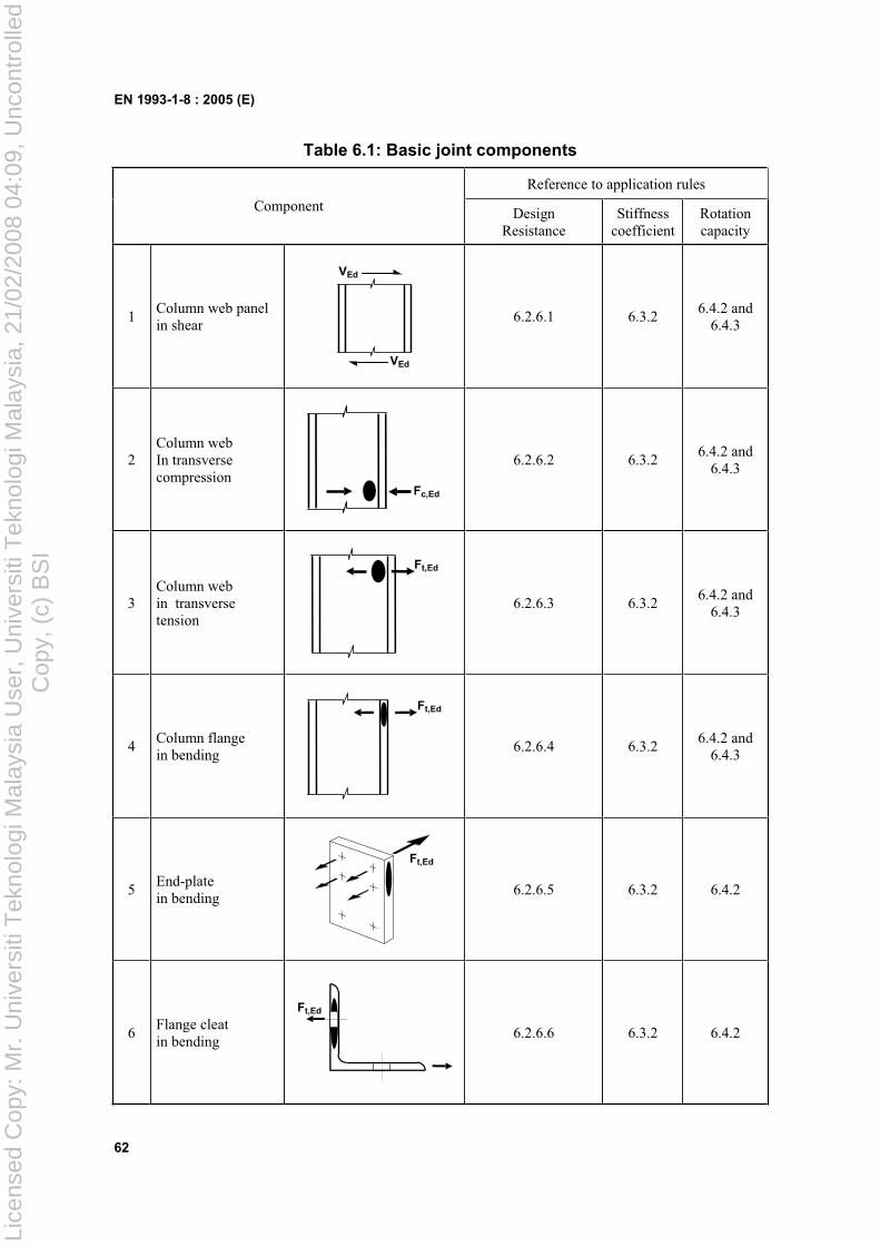
EN 1993-1-8 : 2005 (E)
62
Table 6.1: Basic joint components
Reference to application rules
Component Design Resistance
Stiffness coefficient
Rotation capacity
1Column web panel in shear
VEd
VEd
6.2.6.1 6.3.2 6.4.2 and
6.4.3
2Column web In transverse compression
Fc,Ed
6.2.6.2 6.3.2 6.4.2 and
6.4.3
3Column web in transverse tension
Ft,Ed
6.2.6.3 6.3.2 6.4.2 and
6.4.3
4Column flange in bending
Ft,Ed
6.2.6.4 6.3.2 6.4.2 and
6.4.3
5End-plate in bending
Ft,Ed
6.2.6.5 6.3.2 6.4.2
6Flange cleat in bending
Ft,Ed
6.2.6.6 6.3.2 6.4.2
Lice
nsed
Cop
y: M
r. U
nive
rsiti
Tek
nolo
gi M
alay
sia
Use
r, U
nive
rsiti
Tek
nolo
gi M
alay
sia,
21/
02/2
008
04:0
9, U
ncon
trol
led
Cop
y, (
c) B
SI
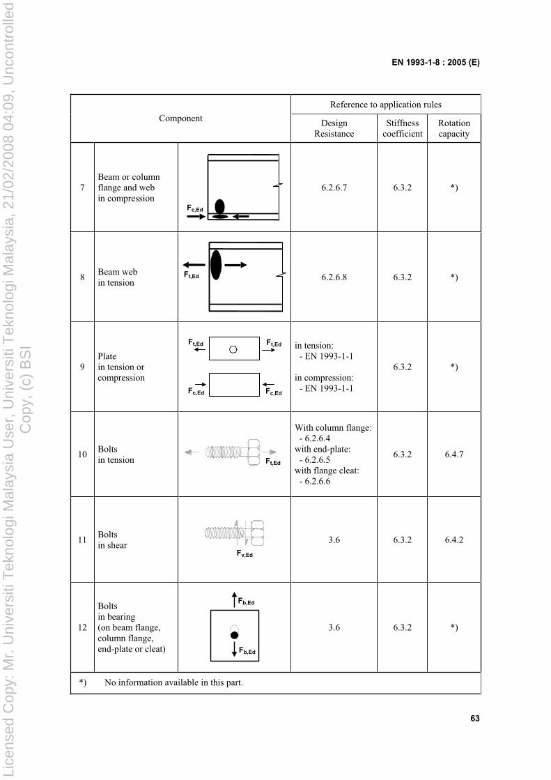
EN 1993-1-8 : 2005 (E)
63
Reference to application rules
Component Design Resistance
Stiffness coefficient
Rotation capacity
7Beam or column flange and web in compression
Fc,Ed
6.2.6.7 6.3.2 *)
8Beam web in tension
Ft,Ed 6.2.6.8 6.3.2 *)
9Platein tension or compression
Fc,Ed Fc,Ed
Ft,EdFt,Ed in tension: - EN 1993-1-1
in compression: - EN 1993-1-1
6.3.2 *)
10Boltsin tension Ft,Ed
With column flange: - 6.2.6.4 with end-plate: - 6.2.6.5 with flange cleat: - 6.2.6.6
6.3.2 6.4.7
11Boltsin shear
Fv,Ed
3.6 6.3.2 6.4.2
12
Boltsin bearing (on beam flange, column flange, end-plate or cleat)
Fb,Ed
Fb,Ed
3.6 6.3.2 *)
*) No information available in this part.
Lice
nsed
Cop
y: M
r. U
nive
rsiti
Tek
nolo
gi M
alay
sia
Use
r, U
nive
rsiti
Tek
nolo
gi M
alay
sia,
21/
02/2
008
04:0
9, U
ncon
trol
led
Cop
y, (
c) B
SI
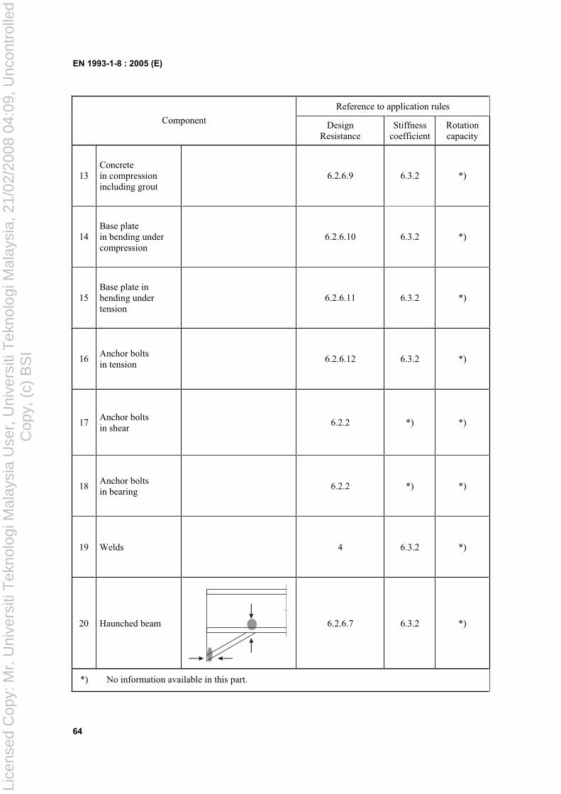
EN 1993-1-8 : 2005 (E)
64
Reference to application rules
Component Design Resistance
Stiffness coefficient
Rotation capacity
13 Concrete in compression including grout
6.2.6.9 6.3.2 *)
14 Base plate in bending under compression
6.2.6.10 6.3.2 *)
15 Base plate in bending under tension
6.2.6.11 6.3.2 *)
16 Anchor bolts in tension
6.2.6.12 6.3.2 *)
17 Anchor bolts in shear
6.2.2 *) *)
18 Anchor bolts in bearing
6.2.2 *) *)
19 Welds 4 6.3.2 *)
20 Haunched beam 6.2.6.7 6.3.2 *)
*) No information available in this part.
Lice
nsed
Cop
y: M
r. U
nive
rsiti
Tek
nolo
gi M
alay
sia
Use
r, U
nive
rsiti
Tek
nolo
gi M
alay
sia,
21/
02/2
008
04:0
9, U
ncon
trol
led
Cop
y, (
c) B
SI
EN 1993-1-8 : 2005 (E)
65
6.2 Design Resistance
6.2.1 Internal forces
(1) The stresses due to the internal forces and moments in a member may be assumed not to affect the design resistances of the basic components of a joint, except as specified in 6.2.1(2) and 6.2.1(3).
(2) The longitudinal stress in a column should be taken into account when determining the design resistance of the column web in compression, see 6.2.6.2(2).
(3) The shear in a column web panel should be taken into account when determining the design resistance of the following basic components:
– column web in transverse compression, see 6.2.6.2;
– column web in transverse tension, see 6.2.6.3.
6.2.2 Shear forces
(1) In welded connections, and in bolted connections with end-plates, the welds connecting the beam web should be designed to transfer the shear force from the connected beam to the joint, without any assistance from the welds connecting the beam flanges.
(2) In bolted connections with end-plates, the design resistance of each bolt-row to combined shear and tension should be verified using the criterion given in Table 3.4, taking into account the total tensile force in the bolt, including any force due to prying action.
NOTE: As a simplification, bolts required to resist in tension may be assumed to provide their full design resistance in tension when it can be shown that the design shear force does not exceed the sum of:
a) the total design shear resistance of those bolts that are not required to resist tension and;
b) (0,4/1,4) times the total design shear resistance of those bolts that are also required to resist tension.
(3) In bolted connections with angle flange cleats, the cleat connecting the compression flange of the beam may be assumed to transfer the shear force in the beam to the column, provided that:
– the gap g between the end of the beam and the face of the column does not exceed the thickness ta of the angle cleat;
– the force does not exceed the design shear resistance of the bolts connecting the cleat to the column;
– the web of the beam satisfies the requirement given in EN 1993-1-5, section 6.
(4) The design shear resistance of a joint may be derived from the distribution of internal forces within that joint, and the design resistances of its basic components to these forces, see Table 6.1.
(5) In base plates if no special elements for resisting shear are provided, such as block or bar shear connectors, it should be demonstrated that either the design friction resistance of the base plate, see 6.2.2(6), or, in cases where the bolt holes are not oversized, the design shear resistance of the anchor bolts, see 6.2.2(7), is sufficient to transfer the design shear force. The design bearing resistance of the block or bar shear connectors with respect to the concrete should be checked according to EN 1992.
(6) In a column base the design friction resistance Ff,Rd between base plate and grout should be derived as follows:
Ff,Rd = Cf,d Nc,Ed ... (6.1)
where:
Lice
nsed
Cop
y: M
r. U
nive
rsiti
Tek
nolo
gi M
alay
sia
Use
r, U
nive
rsiti
Tek
nolo
gi M
alay
sia,
21/
02/2
008
04:0
9, U
ncon
trol
led
Cop
y, (
c) B
SI
EN 1993-1-8 : 2005 (E)
66
Cf,d is the coefficient of friction between base plate and grout layer. The following values may be used:
– for sand-cement mortar Cf,d = 0,20 ; – for other types of grout the coefficient of friction Cf,d should be determined by testing in
accordance with EN 1990, Annex D;
Nc,Ed is the design value of the normal compressive force in the column.
NOTE: If the column is loaded by a tensile normal force, Ff,Rd = 0.
(7) In a column base the design shear resistance of an anchor bolt Fvb,Rd should be taken as the smaller of F1,vb,Rd and F2,vb,Rd where:
– F1,vb,Rd is the design shear resistance of the anchor bolt, see 3.6.1
– F2,vb,Rd = Mb
subb Af ... (6.2)
where:
b = 0,44 - 0,0003 fyb
fyb is the yield strength of the anchor bolt, where 235 N/mm2 fyb 640 N/mm2
(8) The design shear resistance Fv,Rd of a column base plate should be derived as follows:
Fv,Rd = Ff,Rd + n Fvb,Rd ... (6.3)
where:
n is the number of anchor bolts in the base plate.
(9) The concrete and reinforcement used in the base should be designed in accordance with EN 1992.
6.2.3 Bending moments
(1) The design moment resistance of any joint may be derived from the distribution of internal forces within that joint and the design resistances of its basic components to these forces, see Table 6.1.
(2) Provided that the axial force NEd in the connected member does not exceed 5% of the design resistance Np ,Rd of its cross-section, the design moment resistance Mj,Rd of a beam-to column joint or beam splice may be determined using the method given in 6.2.7.
(3) The design moment resistance Mj,Rd of a column base may be determined using the method given in 6.2.8.
(4) In all joints, the sizes of the welds should be such that the design moment resistance of the joint Mj,Rd
is always limited by the design resistance of its other basic components, and not by the design resistance of the welds.
(5) In a beam-to-column joint or beam splice in which a plastic hinge is required to form and rotate under any relevant load case, the welds should be designed to resist the effects of a moment at least equal to the smaller of:
– the design plastic moment resistance of the connected member Mp ,Rd
– times the design moment resistance of the joint Mj,Rd
where:
= 1,4 - for frames in which the bracing system satisfies the criterion (5.1) in EN 1993-1-1 clause 5.2.1(3) with respect to sway;
= 1,7 - for all other cases.
Lice
nsed
Cop
y: M
r. U
nive
rsiti
Tek
nolo
gi M
alay
sia
Use
r, U
nive
rsiti
Tek
nolo
gi M
alay
sia,
21/
02/2
008
04:0
9, U
ncon
trol
led
Cop
y, (
c) B
SI
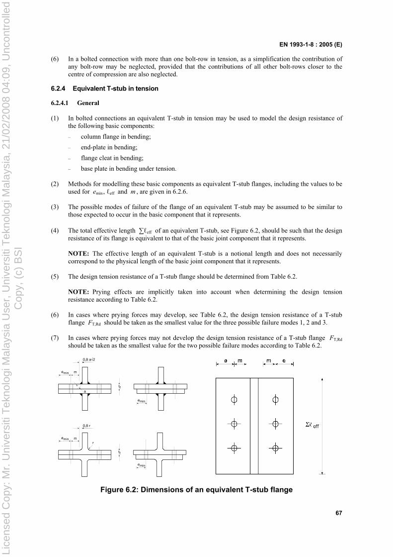
EN 1993-1-8 : 2005 (E)
67
(6) In a bolted connection with more than one bolt-row in tension, as a simplification the contribution of any bolt-row may be neglected, provided that the contributions of all other bolt-rows closer to the centre of compression are also neglected.
6.2.4 Equivalent T-stub in tension
6.2.4.1 General
(1) In bolted connections an equivalent T-stub in tension may be used to model the design resistance of the following basic components:
– column flange in bending;
– end-plate in bending;
– flange cleat in bending;
– base plate in bending under tension.
(2) Methods for modelling these basic components as equivalent T-stub flanges, including the values to be used for emin , eff and m , are given in 6.2.6.
(3) The possible modes of failure of the flange of an equivalent T-stub may be assumed to be similar to those expected to occur in the basic component that it represents.
(4) The total effective length eff of an equivalent T-stub, see Figure 6.2, should be such that the design resistance of its flange is equivalent to that of the basic joint component that it represents.
NOTE: The effective length of an equivalent T-stub is a notional length and does not necessarily correspond to the physical length of the basic joint component that it represents.
(5) The design tension resistance of a T-stub flange should be determined from Table 6.2.
NOTE: Prying effects are implicitly taken into account when determining the design tension resistance according to Table 6.2.
(6) In cases where prying forces may develop, see Table 6.2, the design tension resistance of a T-stub flange FT,Rd should be taken as the smallest value for the three possible failure modes 1, 2 and 3.
(7) In cases where prying forces may not develop the design tension resistance of a T-stub flange FT,Rd
should be taken as the smallest value for the two possible failure modes according to Table 6.2.
Figure 6.2: Dimensions of an equivalent T-stub flange
Lice
nsed
Cop
y: M
r. U
nive
rsiti
Tek
nolo
gi M
alay
sia
Use
r, U
nive
rsiti
Tek
nolo
gi M
alay
sia,
21/
02/2
008
04:0
9, U
ncon
trol
led
Cop
y, (
c) B
SI
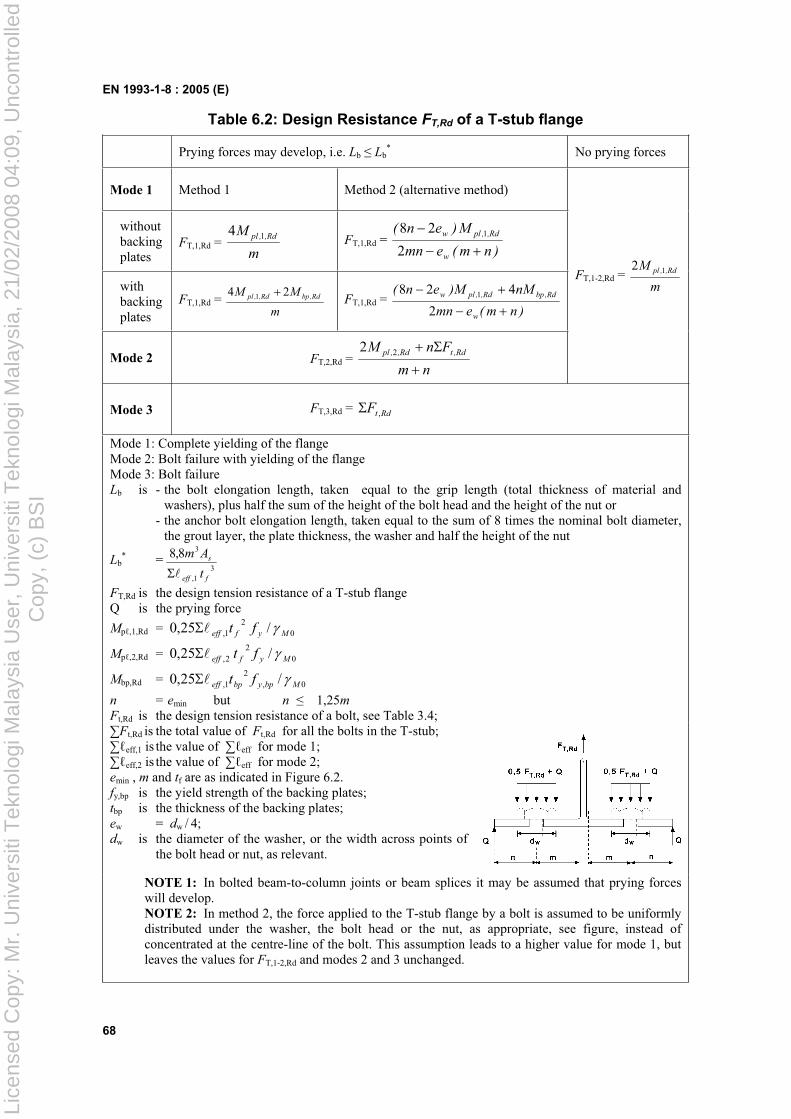
EN 1993-1-8 : 2005 (E)
68
Table 6.2: Design Resistance FT,Rd of a T-stub flange
Prying forces may develop, i.e. Lb Lb* No prying forces
Mode 1 Method 1 Method 2 (alternative method)
without backing plates
FT,1,Rd = m
M Rd,,pl 14FT,1,Rd =
)nm(emn
M)en(
w
Rd,,plw
2
28 1
with backing plates
FT,1,Rd = m
MM Rd,bpRd,,pl 24 1 FT,1,Rd = )nm(emn
nMM)en(
w
Rd,bpRd,,plw
2
428 1
Mode 2 FT,2,Rd = nm
FnM Rd,tRd,,pl 22
FT,1-2,Rd = m
M Rd,,pl 12
Mode 3 FT,3,Rd = RdtF ,
Mode 1: Complete yielding of the flange Mode 2: Bolt failure with yielding of the flange Mode 3: Bolt failure Lb is - the bolt elongation length, taken equal to the grip length (total thickness of material and
washers), plus half the sum of the height of the bolt head and the height of the nut or - the anchor bolt elongation length, taken equal to the sum of 8 times the nominal bolt diameter,
the grout layer, the plate thickness, the washer and half the height of the nut
Lb* =
31,
38,8
feff
s
t
Am
FT,Rd is the design tension resistance of a T-stub flange Q is the prying force
Mp ,1,Rd = 02
1, /25,0 Myfeff ft
Mp ,2,Rd = 02
2, /25,0 Myfeff ft
Mbp,Rd = 0,2
1, /25,0 Mbpybpeff ft
n = emin but n 1,25m
Ft,Rd is the design tension resistance of a bolt, see Table 3.4; Ft,Rd is the total value of Ft,Rd for all the bolts in the T-stub;
eff,1 is the value of eff for mode 1; eff,2 is the value of eff for mode 2;
emin , m and tf are as indicated in Figure 6.2. fy,bp is the yield strength of the backing plates; tbp is the thickness of the backing plates; ew = dw / 4; dw is the diameter of the washer, or the width across points of
the bolt head or nut, as relevant.
NOTE 1: In bolted beam-to-column joints or beam splices it may be assumed that prying forces will develop. NOTE 2: In method 2, the force applied to the T-stub flange by a bolt is assumed to be uniformly distributed under the washer, the bolt head or the nut, as appropriate, see figure, instead of concentrated at the centre-line of the bolt. This assumption leads to a higher value for mode 1, but leaves the values for FT,1-2,Rd and modes 2 and 3 unchanged.
Lice
nsed
Cop
y: M
r. U
nive
rsiti
Tek
nolo
gi M
alay
sia
Use
r, U
nive
rsiti
Tek
nolo
gi M
alay
sia,
21/
02/2
008
04:0
9, U
ncon
trol
led
Cop
y, (
c) B
SI
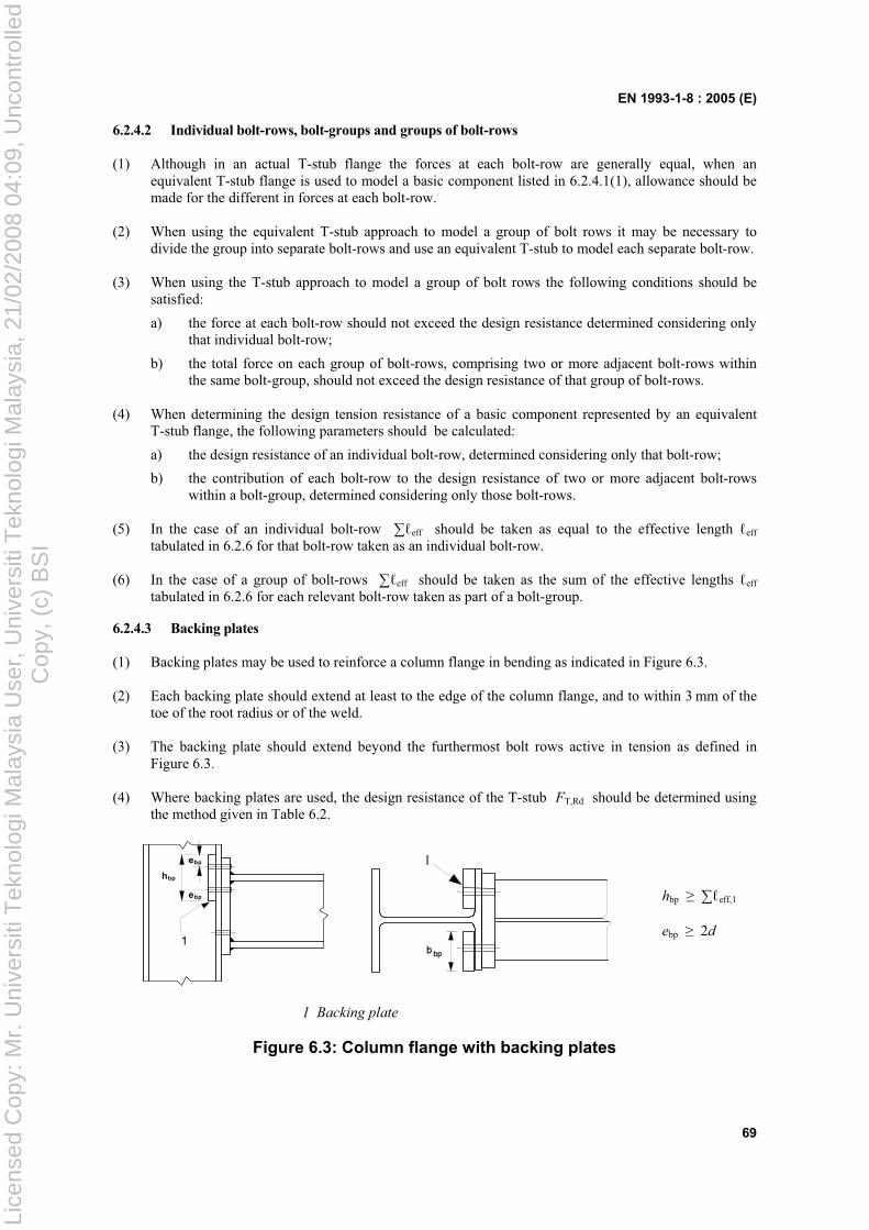
EN 1993-1-8 : 2005 (E)
69
6.2.4.2 Individual bolt-rows, bolt-groups and groups of bolt-rows
(1) Although in an actual T-stub flange the forces at each bolt-row are generally equal, when an equivalent T-stub flange is used to model a basic component listed in 6.2.4.1(1), allowance should be made for the different in forces at each bolt-row.
(2) When using the equivalent T-stub approach to model a group of bolt rows it may be necessary to divide the group into separate bolt-rows and use an equivalent T-stub to model each separate bolt-row.
(3) When using the T-stub approach to model a group of bolt rows the following conditions should be satisfied:
a) the force at each bolt-row should not exceed the design resistance determined considering only that individual bolt-row;
b) the total force on each group of bolt-rows, comprising two or more adjacent bolt-rows within the same bolt-group, should not exceed the design resistance of that group of bolt-rows.
(4) When determining the design tension resistance of a basic component represented by an equivalent T-stub flange, the following parameters should be calculated:
a) the design resistance of an individual bolt-row, determined considering only that bolt-row;
b) the contribution of each bolt-row to the design resistance of two or more adjacent bolt-rows within a bolt-group, determined considering only those bolt-rows.
(5) In the case of an individual bolt-row eff should be taken as equal to the effective length eff
tabulated in 6.2.6 for that bolt-row taken as an individual bolt-row.
(6) In the case of a group of bolt-rows eff should be taken as the sum of the effective lengths eff
tabulated in 6.2.6 for each relevant bolt-row taken as part of a bolt-group.
6.2.4.3 Backing plates
(1) Backing plates may be used to reinforce a column flange in bending as indicated in Figure 6.3.
(2) Each backing plate should extend at least to the edge of the column flange, and to within 3 mm of the toe of the root radius or of the weld.
(3) The backing plate should extend beyond the furthermost bolt rows active in tension as defined in Figure 6.3.
(4) Where backing plates are used, the design resistance of the T-stub FT,Rd should be determined using the method given in Table 6.2.
hbp
ebp
ebp
1
1
hbp eff,1
ebp 2d
1 Backing plate
Figure 6.3: Column flange with backing plates
Lice
nsed
Cop
y: M
r. U
nive
rsiti
Tek
nolo
gi M
alay
sia
Use
r, U
nive
rsiti
Tek
nolo
gi M
alay
sia,
21/
02/2
008
04:0
9, U
ncon
trol
led
Cop
y, (
c) B
SI
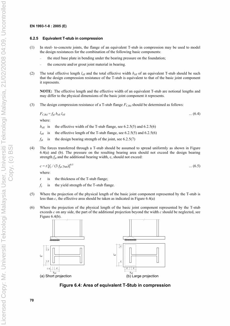
EN 1993-1-8 : 2005 (E)
70
6.2.5 Equivalent T-stub in compression
(1) In steel- to-concrete joints, the flange of an equivalent T-stub in compression may be used to model the design resistances for the combination of the following basic components:
– the steel base plate in bending under the bearing pressure on the foundation;
– the concrete and/or grout joint material in bearing.
(2) The total effective length leff and the total effective width beff of an equivalent T-stub should be such that the design compression resistance of the T-stub is equivalent to that of the basic joint component it represents.
NOTE: The effective length and the effective width of an equivalent T-stub are notional lengths and may differ to the physical dimensions of the basic joint component it represents.
(3) The design compression resistance of a T-stub flange FC,Rd should be determined as follows:
FC,Rd = fjd beff leff ... (6.4)
where:
beff is the effective width of the T-stub flange, see 6.2.5(5) and 6.2.5(6)
leff is the effective length of the T-stub flange, see 6.2.5(5) and 6.2.5(6)
fjd is the design bearing strength of the joint, see 6.2.5(7)
(4) The forces transferred through a T-stub should be assumed to spread uniformly as shown in Figure 6.4(a) and (b). The pressure on the resulting bearing area should not exceed the design bearing strength fjd and the additional bearing width, c, should not exceed:
c = t [fy / (3 fjd M0)]0.5 ... (6.5)
where:
t is the thickness of the T-stub flange;
fy is the yield strength of the T-stub flange.
(5) Where the projection of the physical length of the basic joint component represented by the T-stub is less than c, the effective area should be taken as indicated in Figure 6.4(a)
(6) Where the projection of the physical length of the basic joint component represented by the T-stub exceeds c on any side, the part of the additional projection beyond the width c should be neglected, see Figure 6.4(b).
leff
beff
cc
c
c
leff
beff
cc
c
c
(a) Short projection (b) Large projection
Figure 6.4: Area of equivalent T-Stub in compression
Lice
nsed
Cop
y: M
r. U
nive
rsiti
Tek
nolo
gi M
alay
sia
Use
r, U
nive
rsiti
Tek
nolo
gi M
alay
sia,
21/
02/2
008
04:0
9, U
ncon
trol
led
Cop
y, (
c) B
SI
EN 1993-1-8 : 2005 (E)
71
(7) The design bearing strength of the joint fjd should be determined from:
fjd = j FRdu / (beff leff) ... (6.6)
where:
j is the foundation joint material coefficient, which may be taken as 2/3 provided that the characteristic strength of the grout is not less than 0,2 times the characteristic strength of the concrete foundation and the thickness of the grout is not greater than 0,2 times the smallest width of the steel base plate. In cases where the thickness of the grout is more than 50 mm, the characteristic strength of the grout should be at least the same as that of the concrete foundation.
FRdu is the concentrated design resistance force given in EN 1992, where Ac0 is to be taken as (beff
leff).
6.2.6 Design Resistance of basic components
6.2.6.1 Column web panel in shear
(1) The design methods given in 6.2.6.1(2) to 6.2.6.1(14) are valid provided the column web slenderness satisfies the condition d/tw 69 .
(2) For a single-sided joint, or for a double-sided joint in which the beam depths are similar, the design plastic shear resistance Vwp,Rd of an unstiffened column web panel, subject to a design shear force Vwp,Ed , see 5.3(3), should be obtained using:
Vwp,Rd = 0
,
3
9,0
M
vcwcy Af ... (6.7)
where:
Avc is the shear area of the column, see EN 1993-1-1.
(3) The design shear resistance may be increased by the use of stiffeners or supplementary web plates.
(4) Where transverse web stiffeners are used in both the compression zone and the tension zone, the design plastic shear resistance of the column web panel Vwp,Rd may be increased by Vwp,add,Rd given by:
Vwp,add,Rd = s
Rdfcpl
d
M ,,4 but Vwp,add,Rd
s
RdstplRdfcpl
d
MM ,,,, 22... (6.8)
where:
ds is the distance between the centrelines of the stiffeners;
Mp ,fc,Rd is the design plastic moment resistance of a column flange
Mp ,st,Rd is the design plastic moment resistance of a stiffener.
NOTE: In welded joints, the transverse stiffeners should be aligned with the corresponding beam flange.
(5) When diagonal web stiffeners are used the design plastic shear resistance of a column web should be determined according to EN 1993-1-1.
NOTE: In double-sided beam-to-column joint configurations without diagonal stiffeners on the column webs, the two beams are assumed to have similar depths.
(6) Where a column web is reinforced by adding a supplementary web plate, see Figure 6.5, the shear area Avc may be increased by bs twc. If a further supplementary web plate is added on the other side of the web, no further increase of the shear area should be made.
Lice
nsed
Cop
y: M
r. U
nive
rsiti
Tek
nolo
gi M
alay
sia
Use
r, U
nive
rsiti
Tek
nolo
gi M
alay
sia,
21/
02/2
008
04:0
9, U
ncon
trol
led
Cop
y, (
c) B
SI
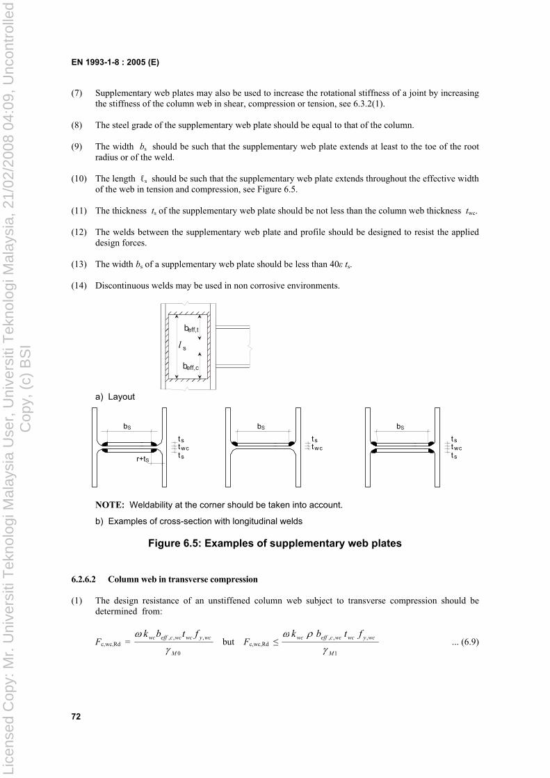
EN 1993-1-8 : 2005 (E)
72
(7) Supplementary web plates may also be used to increase the rotational stiffness of a joint by increasing the stiffness of the column web in shear, compression or tension, see 6.3.2(1).
(8) The steel grade of the supplementary web plate should be equal to that of the column.
(9) The width bs should be such that the supplementary web plate extends at least to the toe of the root radius or of the weld.
(10) The length s should be such that the supplementary web plate extends throughout the effective width of the web in tension and compression, see Figure 6.5.
(11) The thickness ts of the supplementary web plate should be not less than the column web thickness twc.
(12) The welds between the supplementary web plate and profile should be designed to resist the applied design forces.
(13) The width bs of a supplementary web plate should be less than 40 ts.
(14) Discontinuous welds may be used in non corrosive environments.
beff,c
s
beff,t
l
a) Layout
tt
tw c s
s
bS
r+tS
t t t t
tw c w c s s
s
bS bS
NOTE: Weldability at the corner should be taken into account.
b) Examples of cross-section with longitudinal welds
Figure 6.5: Examples of supplementary web plates
6.2.6.2 Column web in transverse compression
(1) The design resistance of an unstiffened column web subject to transverse compression should be determined from:
Fc,wc,Rd = 0
,,,
M
wcywcwcceffwc ftbk but Fc,wc,Rd
1
,,,
M
wcywcwcceffwc ftbk ... (6.9)
Lice
nsed
Cop
y: M
r. U
nive
rsiti
Tek
nolo
gi M
alay
sia
Use
r, U
nive
rsiti
Tek
nolo
gi M
alay
sia,
21/
02/2
008
04:0
9, U
ncon
trol
led
Cop
y, (
c) B
SI
EN 1993-1-8 : 2005 (E)
73
where:
is a reduction factor to allow for the possible effects of interaction with shear in the column web panel according to Table 6.3;
beff,c,wc is the effective width of column web in compression:
– for a welded connection:
beff,c,wc = )(522 stat fcbfb ... (6.10)
ac , rc and ab are as indicated in Figure 6.6.
– for bolted end-plate connection:
beff,c,wc = pfcpfb sstat )(522 ... (6.11)
sp is the length obtained by dispersion at 45° through the end-plate (at least tp and, provided that the length of end-plate below the flange is sufficient, up to 2tp).
– for bolted connection with angle flange cleats: beff,c,wc = )(56,02 strt fcaa ... (6.12)
– for a rolled I or H section column: s = rc
– for a welded I or H section column: s = ca2
is the reduction factor for plate buckling:
– if p 0,72: = 1,0 ... (6.13a)
– if p > 0,72: = ( p 0,2)/ p2 ... (6.13b)
p is the plate slenderness:
p = 2
,,,932,0wc
wcywcwcceff
Et
fdb ... (6.13c)
– for a rolled I or H section column: dwc = hc 2( tfc + rc )
– for a welded I or H section column: dwc = hc 2( tfc + ca2 )
kwc is a reduction factor and is given in 6.2.6.2(2).
Table 6.3: Reduction factor for interaction with shear
Transformation parameter Reduction factor
0 0,5 = 1
0,5 < < 1 = 1 + 2 (1 ) (1 1)
= 1 = 1
1 < < 2 = 1 + ( 1) ( 2 1)
= 2 = 2
1 = 2
,, )/(3,11
1
vcwcwcceff Atb2 =
2,, )/(2,51
1
vcwcwcceff Atb
Avc is the shear area of the column, see 6.2.6.1;
is the transformation parameter, see 5.3(7).
Lice
nsed
Cop
y: M
r. U
nive
rsiti
Tek
nolo
gi M
alay
sia
Use
r, U
nive
rsiti
Tek
nolo
gi M
alay
sia,
21/
02/2
008
04:0
9, U
ncon
trol
led
Cop
y, (
c) B
SI
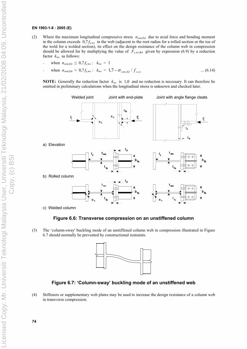
EN 1993-1-8 : 2005 (E)
74
(2) Where the maximum longitudinal compressive stress com,Ed due to axial force and bending moment in the column exceeds 0,7 fy,wc in the web (adjacent to the root radius for a rolled section or the toe of the weld for a welded section), its effect on the design resistance of the column web in compression should be allowed for by multiplying the value of Fc,wc,Rd given by expression (6.9) by a reduction factor kwc as follows:
– when com,Ed 0,7 fy,wc : kwc = 1
– when com,Ed > 0,7 fy,wc : kwc = wcyEdcom f ,, /7,1 ... (6.14)
NOTE: Generally the reduction factor kwc is 1,0 and no reduction is necessary. It can therefore be omitted in preliminary calculations when the longitudinal stress is unknown and checked later.
Welded joint Joint with end-plate Joint with angle flange cleats
a) Elevation
b) Rolled column
c) Welded column
Figure 6.6: Transverse compression on an unstiffened column
(3) The ‘column-sway' buckling mode of an unstiffened column web in compression illustrated in Figure 6.7 should normally be prevented by constructional restraints.
Figure 6.7: ‘Column-sway’ buckling mode of an unstiffened web
(4) Stiffeners or supplementary web plates may be used to increase the design resistance of a column web in transverse compression.
Lice
nsed
Cop
y: M
r. U
nive
rsiti
Tek
nolo
gi M
alay
sia
Use
r, U
nive
rsiti
Tek
nolo
gi M
alay
sia,
21/
02/2
008
04:0
9, U
ncon
trol
led
Cop
y, (
c) B
SI
EN 1993-1-8 : 2005 (E)
75
(5) Transverse stiffeners or appropriate arrangements of diagonal stiffeners may be used (in association with or as an alternative to transverse stiffeners) in order to increase the design resistance of the column web in compression.
NOTE: In welded joints, the transverse stiffeners should be aligned with the corresponding beam flange. In bolted joints, the stiffener in the compression zone should be aligned with the centre of compression as defined Figure 6.15.
(6) Where an unstiffened column web is reinforced by adding a supplementary web plate conforming with 6.2.6.1, the effective thickness of the web may be taken as 1,5 twc if one supplementary web plate is added, or 2,0 twc if supplementary web plates are added to both sides of the web. In calculating the reduction factor for the possible effects of shear stress, the shear area Avc of the web may be increased only to the extent permitted when determining its design shear resistance, see 6.2.6.1(6).
6.2.6.3 Column web in transverse tension
(1) The design resistance of an unstiffened column web subject to transverse tension should be determined from:
Ft,wc,Rd = 0
,wc,, t
M
wcywcteff fb ... (6.15)
where:
is a reduction factor to allow for the interaction with shear in the column web panel.
(2) For a welded connection, the effective width beff,t,wc of a column web in tension should be obtained using:
beff,t,wc = )(522 stat fcbfb ... (6.16)
where:
– for a rolled I or H section column: s = rc
– for a welded I or H section column: s = ca2
where:
ac and rc are as indicated in Figure 6.8 and ab is as indicated in Figure 6.6.
(3) For a bolted connection, the effective width beff,t,wc of column web in tension should be taken as equal to the effective length of equivalent T-stub representing the column flange, see 6.2.6.4.
(4) The reduction factor to allow for the possible effects of shear in the column web panel should be determined from Table 6.3, using the value of beff,t,wc given in 6.2.6.3(2) or 6.2.6.3(3) as appropriate.
(5) Stiffeners or supplementary web plates may be used to increase the design tension resistance of a column web.
(6) Transverse stiffeners and/or appropriate arrangements of diagonal stiffeners may be used to increase the design resistance of the column web in tension.
NOTE: In welded joints, the transverse stiffeners are normally aligned with the corresponding beam flange.
Lice
nsed
Cop
y: M
r. U
nive
rsiti
Tek
nolo
gi M
alay
sia
Use
r, U
nive
rsiti
Tek
nolo
gi M
alay
sia,
21/
02/2
008
04:0
9, U
ncon
trol
led
Cop
y, (
c) B
SI
EN 1993-1-8 : 2005 (E)
76
(7) The welds connecting diagonal stiffeners to the column flange should be fill-in welds with a sealing run providing a combined throat thickness equal to the thickness of the stiffeners.
(8) Where an unstiffened column web is reinforced by adding supplementary web plates conforming with 6.2.6.1, the design tension resistance depends on the throat thickness of the longitudinal welds connecting the supplementary web plates. The effective thickness of the web tw,eff should be taken as follows:
– when the longitudinal welds are full penetration butt welds with a throat thickness a ts then:
– for one supplementary web plate: tw,eff = 1,5 twc ... (6.17)
– for supplementary web plates both sides: tw,eff = 2,0 twc ... (6.18)
– when the longitudinal welds are fillet welds with a throat thickness a 2/st then for either
one or two supplementary web plates:
– for steel grades S 235, S 275 or S 355: tw,eff = 1,4 twc ... (6.19a)
– for steel grades S 420 or S 460: tw,eff = 1,3 twc ... (6.19b)
(9) In calculating the reduction factor for the possible effects of shear stress, the shear area Avc of a column web reinforced by adding supplementary web plates may be increased only to the extent permitted when determining its design shear resistance, see 6.2.6.1(6).
6.2.6.4 Column flange in tranverse bending
6.2.6.4.1 Unstiffened column flange, bolted connection
(1) The design resistance and failure mode of an unstiffened column flange in tranverse bending, together with the associated bolts in tension, should be taken as similar to those of an equivalent T-stub flange, see 6.2.4, for both:
– each individual bolt-row required to resist tension;
– each group of bolt-rows required to resist tension.
(2) The dimensions emin and m for use in 6.2.4 should be determined from Figure 6.8.
(3) The effective length of equivalent T-stub flange should be determined for the individual bolt-rows and the bolt-group in accordance with 6.2.4.2 from the values given for each bolt-row in Table 6.4.
Lice
nsed
Cop
y: M
r. U
nive
rsiti
Tek
nolo
gi M
alay
sia
Use
r, U
nive
rsiti
Tek
nolo
gi M
alay
sia,
21/
02/2
008
04:0
9, U
ncon
trol
led
Cop
y, (
c) B
SI
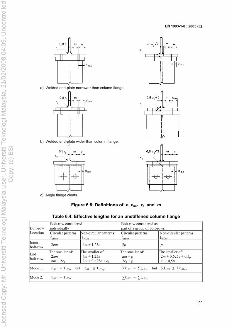
EN 1993-1-8 : 2005 (E)
77
mrc
0,8 rc e
emin
a) Welded end-plate narrower than column flange.
mrc
0,8 rc emin
b) Welded end-plate wider than column flange.
mrc
0,8 rc e
e min
c) Angle flange cleats.
Figure 6.8: Definitions of e, emin, rc and m
Table 6.4: Effective lengths for an unstiffened column flange
Bolt-row considered individually
Bolt-row considered as part of a group of bolt-rowsBolt-row
Location Circular patterns eff,cp
Non-circular patterns eff,nc
Circular patterns eff,cp
Non-circular patterns eff,nc
Innerbolt-row
2 m 4m + 1,25e 2p p
End bolt-row
The smaller of: 2 m
m + 2e1
The smaller of: 4m + 1,25e
2m + 0,625e + e1
The smaller of: m + p
2e1 + p
The smaller of: 2m + 0,625e + 0,5p
e1 + 0,5p
Mode 1: eff,1 = eff,nc but eff,1 eff,cp eff,1 = eff,nc but eff,1 eff,cp
Mode 2: eff,2 = eff,nc eff,2 = eff,nc
Lice
nsed
Cop
y: M
r. U
nive
rsiti
Tek
nolo
gi M
alay
sia
Use
r, U
nive
rsiti
Tek
nolo
gi M
alay
sia,
21/
02/2
008
04:0
9, U
ncon
trol
led
Cop
y, (
c) B
SI
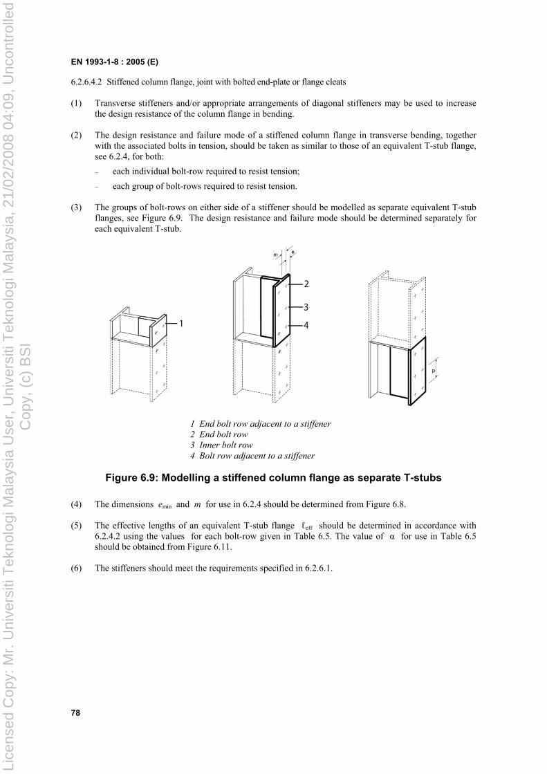
EN 1993-1-8 : 2005 (E)
78
6.2.6.4.2 Stiffened column flange, joint with bolted end-plate or flange cleats
(1) Transverse stiffeners and/or appropriate arrangements of diagonal stiffeners may be used to increase the design resistance of the column flange in bending.
(2) The design resistance and failure mode of a stiffened column flange in transverse bending, together with the associated bolts in tension, should be taken as similar to those of an equivalent T-stub flange, see 6.2.4, for both:
– each individual bolt-row required to resist tension;
– each group of bolt-rows required to resist tension.
(3) The groups of bolt-rows on either side of a stiffener should be modelled as separate equivalent T-stub flanges, see Figure 6.9. The design resistance and failure mode should be determined separately for each equivalent T-stub.
1 End bolt row adjacent to a stiffener
2 End bolt row
3 Inner bolt row
4 Bolt row adjacent to a stiffener
Figure 6.9: Modelling a stiffened column flange as separate T-stubs
(4) The dimensions emin and m for use in 6.2.4 should be determined from Figure 6.8.
(5) The effective lengths of an equivalent T-stub flange eff should be determined in accordance with 6.2.4.2 using the values for each bolt-row given in Table 6.5. The value of for use in Table 6.5 should be obtained from Figure 6.11.
(6) The stiffeners should meet the requirements specified in 6.2.6.1.
Lice
nsed
Cop
y: M
r. U
nive
rsiti
Tek
nolo
gi M
alay
sia
Use
r, U
nive
rsiti
Tek
nolo
gi M
alay
sia,
21/
02/2
008
04:0
9, U
ncon
trol
led
Cop
y, (
c) B
SI
EN 1993-1-8 : 2005 (E)
79
Table 6.5: Effective lengths for a stiffened column flange
Bolt-row considered individually
Bolt-row considered as part of a group of bolt-rowsBolt-row
Location Circular patterns eff,cp
Non-circular patterns eff,nc
Circular patterns eff,cp
Non-circular patterns eff,nc
Bolt-row adjacent to a stiffener
2 m m m + p 0,5p + m
(2m + 0,625e)Other inner bolt-row
2 m 4m + 1,25e 2p p
Other end bolt-row
The smaller of: 2 m
m + 2e1
The smaller of: 4m + 1,25e
2m + 0,625e + e1
The smaller of: m + p
2e1 + p
The smaller of: 2m + 0,625e + 0,5p
e1 + 0,5p
End bolt-row adjacent to a stiffener
The smaller of: 2 m
m + 2e1
e1 + m
(2m + 0,625e)not relevant not relevant
For Mode 1: eff,1 = eff,nc but eff,1 eff,cp eff,1 = eff,nc but eff,1 eff,cp
For Mode 2: eff,2 = eff,nc eff,2 = eff,nc
should be obtained from Figure 6.11.
6.2.6.4.3 Unstiffened column flange, welded connection
(1) In a welded joint, the design resistance Ffc,Rd of an unstiffened column flange in bending, due to tension or compression from a beam flange, should be obtained using:
Ffc,Rd = 0,,, / Mfbfbfcbeff ftb ... (6.20)
where:
beff,b,fc is the effective breath beff defined in 4.10 where the beam flange is considered as a plate.
NOTE: See also the requirements specified in 4.10(4) and 4.10(6).
6.2.6.5 End-plate in bending
(1) The design resistance and failure mode of an end-plate in bending, together with the associated bolts in tension, should be taken as similar to those of an equivalent T-stub flange, see 6.2.4 for both:
– each individual bolt-row required to resist tension;
– each group of bolt-rows required to resist tension.
(2) The groups of bolt-rows either side of any stiffener connected to the end-plate should be treated as separate equivalent T-stubs. In extended end-plates, the bolt-row in the extended part should also be treated as a separate equivalent T-stub, see Figure 6.10. The design resistance and failure mode should be determined separately for each equivalent T-stub.
(3) The dimension emin required for use in 6.2.4 should be obtained from Figure 6.8 for that part of the end-plate located between the beam flanges. For the end-plate extension emin should be taken as equal to ex , see Figure 6.10.
(4) The effective length of an equivalent T-stub flange eff should be determined in accordance with 6.2.4.2 using the values for each bolt-row given in Table 6.6.
Lice
nsed
Cop
y: M
r. U
nive
rsiti
Tek
nolo
gi M
alay
sia
Use
r, U
nive
rsiti
Tek
nolo
gi M
alay
sia,
21/
02/2
008
04:0
9, U
ncon
trol
led
Cop
y, (
c) B
SI
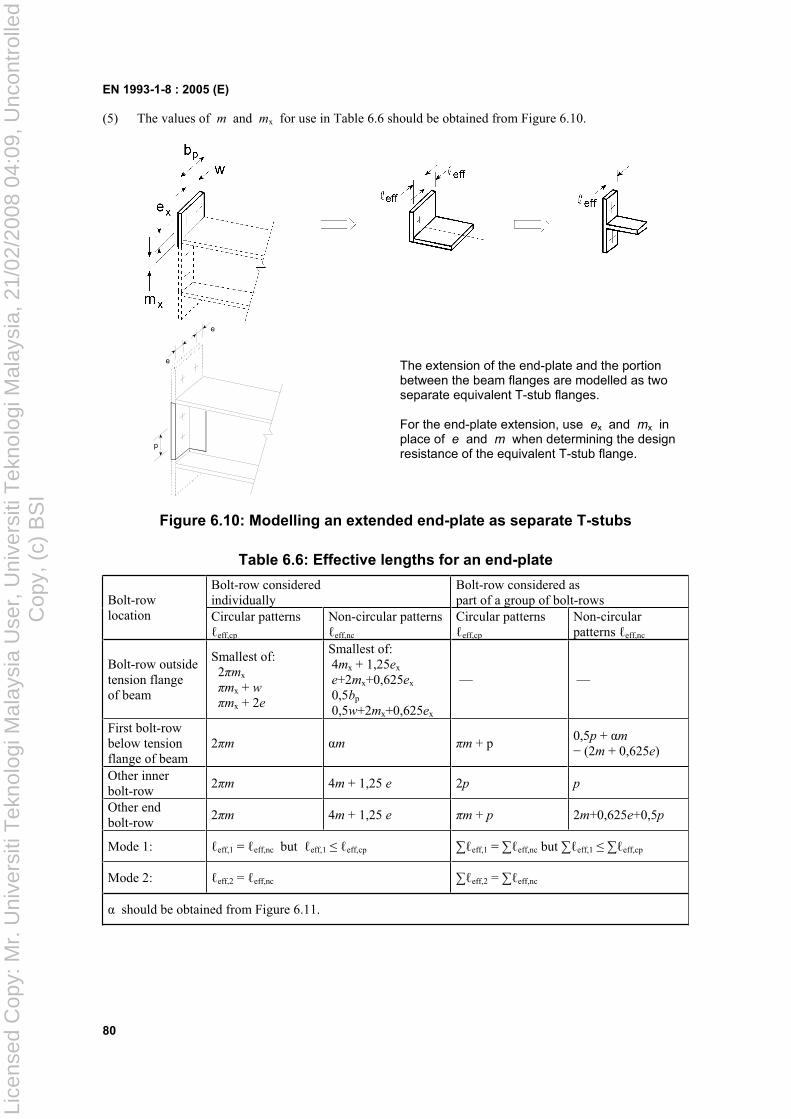
EN 1993-1-8 : 2005 (E)
80
(5) The values of m and mx for use in Table 6.6 should be obtained from Figure 6.10.
p
e
e
The extension of the end-plate and the portion between the beam flanges are modelled as two separate equivalent T-stub flanges.
For the end-plate extension, use ex and mx in place of e and m when determining the design resistance of the equivalent T-stub flange.
Figure 6.10: Modelling an extended end-plate as separate T-stubs
Table 6.6: Effective lengths for an end-plate
Bolt-row considered individually
Bolt-row considered as part of a group of bolt-rowsBolt-row
location Circular patterns eff,cp
Non-circular patterns eff,nc
Circular patterns eff,cp
Non-circularpatterns eff,nc
Bolt-row outside tension flange of beam
Smallest of: 2 mx
mx + wmx + 2e
Smallest of: 4mx + 1,25ex
e+2mx+0,625ex
0,5bp
0,5w+2mx+0,625ex
— —
First bolt-row below tension flange of beam
2 m m m + p0,5p + m
(2m + 0,625e)
Other inner bolt-row
2 m 4m + 1,25 e 2p p
Other end bolt-row
2 m 4m + 1,25 e m + p 2m+0,625e+0,5p
Mode 1: eff,1 = eff,nc but eff,1 eff,cp eff,1 = eff,nc but eff,1 eff,cp
Mode 2: eff,2 = eff,nc eff,2 = eff,nc
should be obtained from Figure 6.11.
Lice
nsed
Cop
y: M
r. U
nive
rsiti
Tek
nolo
gi M
alay
sia
Use
r, U
nive
rsiti
Tek
nolo
gi M
alay
sia,
21/
02/2
008
04:0
9, U
ncon
trol
led
Cop
y, (
c) B
SI
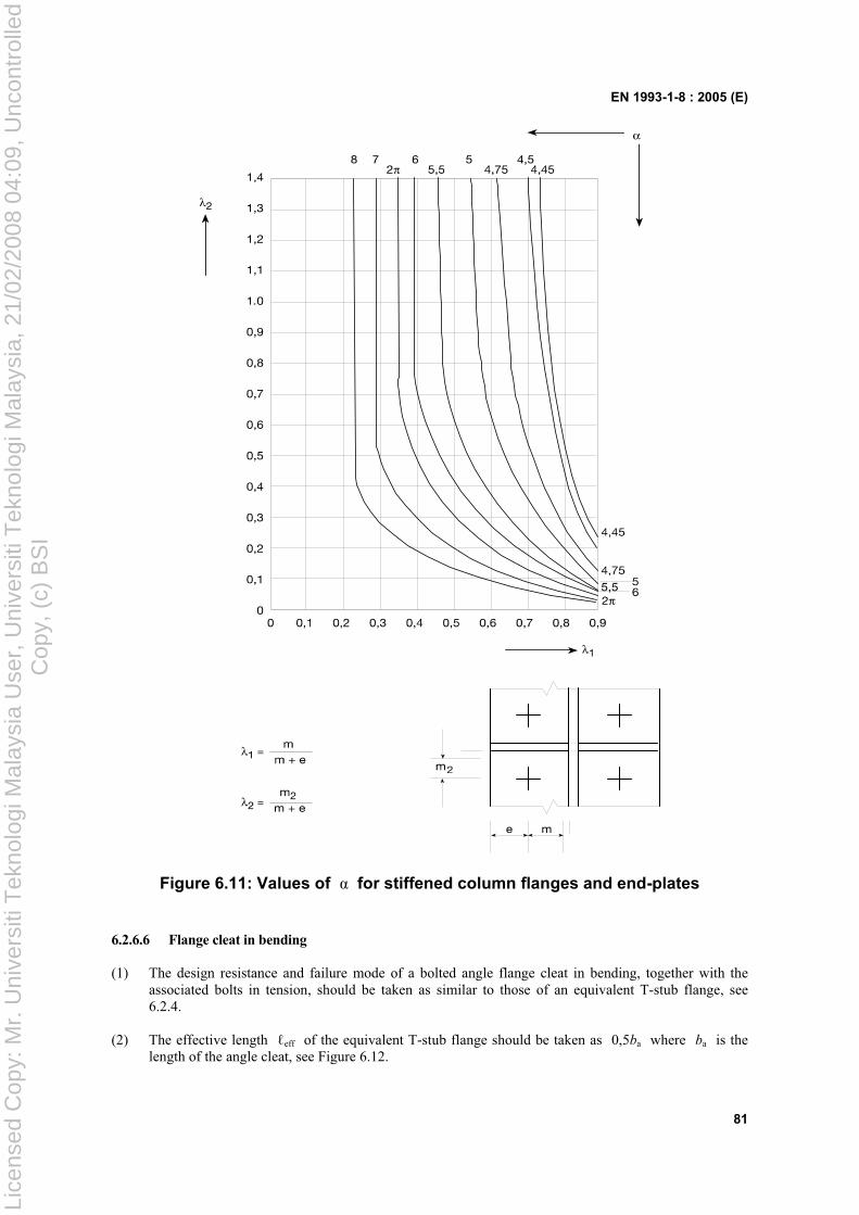
EN 1993-1-8 : 2005 (E)
81
Figure 6.11: Values of for stiffened column flanges and end-plates
6.2.6.6 Flange cleat in bending
(1) The design resistance and failure mode of a bolted angle flange cleat in bending, together with the associated bolts in tension, should be taken as similar to those of an equivalent T-stub flange, see 6.2.4.
(2) The effective length eff of the equivalent T-stub flange should be taken as 0,5ba where ba is the length of the angle cleat, see Figure 6.12.
Lice
nsed
Cop
y: M
r. U
nive
rsiti
Tek
nolo
gi M
alay
sia
Use
r, U
nive
rsiti
Tek
nolo
gi M
alay
sia,
21/
02/2
008
04:0
9, U
ncon
trol
led
Cop
y, (
c) B
SI
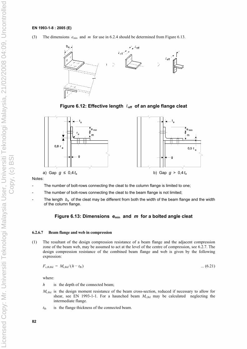
EN 1993-1-8 : 2005 (E)
82
(3) The dimensions emin and m for use in 6.2.4 should be determined from Figure 6.13.
Figure 6.12: Effective length eff of an angle flange cleat
a) Gap g 0,4 ta b) Gap g > 0,4 ta
Notes:
- The number of bolt-rows connecting the cleat to the column flange is limited to one;
- The number of bolt-rows connecting the cleat to the beam flange is not limited;
- The length ba of the cleat may be different from both the width of the beam flange and the width of the column flange.
Figure 6.13: Dimensions emin and m for a bolted angle cleat
6.2.6.7 Beam flange and web in compression
(1) The resultant of the design compression resistance of a beam flange and the adjacent compression zone of the beam web, may be assumed to act at the level of the centre of compression, see 6.2.7. The design compression resistance of the combined beam flange and web is given by the following expression:
Fc,fb,Rd = Mc,Rd/(h tfb ) ... (6.21)
where:
h is the depth of the connected beam;
Mc,Rd is the design moment resistance of the beam cross-section, reduced if necessary to allow for shear, see EN 1993-1-1. For a haunched beam Mc,Rd may be calculated neglecting the intermediate flange.
tfb is the flange thickness of the connected beam.
Lice
nsed
Cop
y: M
r. U
nive
rsiti
Tek
nolo
gi M
alay
sia
Use
r, U
nive
rsiti
Tek
nolo
gi M
alay
sia,
21/
02/2
008
04:0
9, U
ncon
trol
led
Cop
y, (
c) B
SI
EN 1993-1-8 : 2005 (E)
83
If the height of the beam including the haunch exceeds 600 mm the contribution of the beam web to the design compression resistance should be limited to 20%.
(2) If a beam is reinforced with haunches they should be arranged such that:
– the steel grade of the haunch should match that of the member;
– the flange size and the web thickness of the haunch should not be less than that of the member;
– the angle of the haunch flange to the flange of the member should not be greater than 45°;
– the length of stiff bearing ss should be taken as equal to the thickness of the haunch flange parallel to the beam.
(3) If a beam is reinforced with haunches, the design resistance of beam web in compression should be determined according to 6.2.6.2.
6.2.6.8 Beam web in tension
(1) In a bolted end-plate connection, the design tension resistance of the beam web should be obtained from:
Ft,wb,Rd = 0,,, / Mwbywbwbteff ftb ... (6.22)
(2) The effective width beff,t,wb of the beam web in tension should be taken as equal to the effective length of the equivalent T-stub representing the end-plate in bending, obtained from 6.2.6.5 for an individual bolt-row or a bolt-group.
6.2.6.9 Concrete in compression including grout
(1) The design bearing strength of the joint between the base plate and its concrete support should be determined taking account of the material properties and dimensions of both the grout and the concrete support. The concrete support should be designed according to EN 1992.
(2) The design resistance of concrete in compression, including grout, together with the associated base plate in bending Fc,pl,Rd, should be taken as similar to those of an equivalent T-stub, see 6.2.5.
6.2.6.10 Base plate in bending under compression
(1) The design resistance of a base plate in bending under compression, together with concrete slab on which the column base is placed Fc,pl,Rd, should be taken as similar to those of an equivalent T-stub, see 6.2.5.
6.2.6.11 Base plate in bending under tension
(1) The design resistance and failure mode of a base plate in bending under tension, together with the associated anchor bolts in tension Ft,pl,Rd, may be determined using the rules given in 6.2.6.5.
(2) In the case of base plates prying forces which may develop should not be taken into consideration.
6.2.6.12 Anchor bolt in tension
(1) Anchor bolts should be designed to resist the effects of the design loads. They should provide design resistance to tension due to uplift forces and bending moments where appropriate.
(2) When calculating the tension forces in the anchor bolts due to bending moments, the lever arm should not be taken as more than the distance between the centroid of the bearing area on the compression side and the centroid of the bolt group on the tension side.
NOTE: Tolerances on the positions of the anchor bolts may have an influence.
Lice
nsed
Cop
y: M
r. U
nive
rsiti
Tek
nolo
gi M
alay
sia
Use
r, U
nive
rsiti
Tek
nolo
gi M
alay
sia,
21/
02/2
008
04:0
9, U
ncon
trol
led
Cop
y, (
c) B
SI
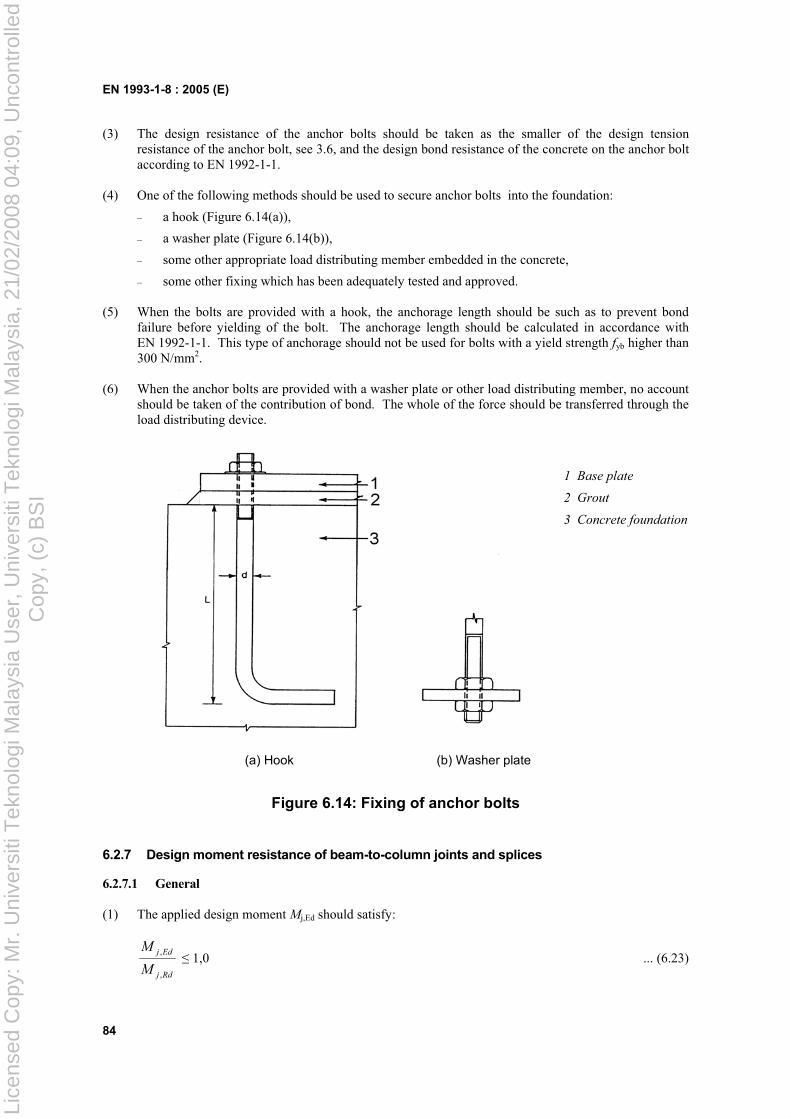
EN 1993-1-8 : 2005 (E)
84
(3) The design resistance of the anchor bolts should be taken as the smaller of the design tension resistance of the anchor bolt, see 3.6, and the design bond resistance of the concrete on the anchor bolt according to EN 1992-1-1.
(4) One of the following methods should be used to secure anchor bolts into the foundation:
– a hook (Figure 6.14(a)),
– a washer plate (Figure 6.14(b)),
– some other appropriate load distributing member embedded in the concrete,
– some other fixing which has been adequately tested and approved.
(5) When the bolts are provided with a hook, the anchorage length should be such as to prevent bond failure before yielding of the bolt. The anchorage length should be calculated in accordance with EN 1992-1-1. This type of anchorage should not be used for bolts with a yield strength fyb higher than 300 N/mm2.
(6) When the anchor bolts are provided with a washer plate or other load distributing member, no account should be taken of the contribution of bond. The whole of the force should be transferred through the load distributing device.
1 Base plate
2 Grout
3 Concrete foundation
(a) Hook (b) Washer plate
Figure 6.14: Fixing of anchor bolts
6.2.7 Design moment resistance of beam-to-column joints and splices
6.2.7.1 General
(1) The applied design moment Mj,Ed should satisfy:
Rdj
Edj
M
M
,
, 1,0 ... (6.23)
Lice
nsed
Cop
y: M
r. U
nive
rsiti
Tek
nolo
gi M
alay
sia
Use
r, U
nive
rsiti
Tek
nolo
gi M
alay
sia,
21/
02/2
008
04:0
9, U
ncon
trol
led
Cop
y, (
c) B
SI
EN 1993-1-8 : 2005 (E)
85
(2) The methods given in 6.2.7 for determining the design moment resistance of a joint Mj,Rd do not take account of any co-existing axial force NEd in the connected member. They should not be used if the axial force in the connected member exceeds 5% of the design plastic resistance Np ,Rd of its cross-section.
(3) If the axial force NEd in the connected beam exceeds 5% of the design resistance, Npl,Rd , the following conservative method may be used:
Rdj
Edj
Rdj
Edj
N
N
M
M
,
,
,
, 1,0 ... (6.24)
where:
Mj.Rd is the design moment resistance of the joint, assuming no axial force;
Nj.Rd is the axial design resistance of the joint, assuming no applied moment.
(4) The design moment resistance of a welded joint should be determined as indicated in Figure 6.15(a).
(5) The design moment resistance of a bolted joint with a flush end-plate that has only one bolt-row in tension (or in which only one bolt-row in tension is considered, see 6.2.3(6)) should be determined as indicated in Figure 6.15(c).
(6) The design moment resistance of a bolted joint with angle flange cleats should be determined as indicated in Figure 6.15(b).
(7) The design moment resistance of a bolted end-plate joint with more than one row of bolts in tension should generally be determined as specified in 6.2.7.2.
(8) As a conservative simplification, the design moment resistance of an extended end-plate joint with only two rows of bolts in tension may be approximated as indicated in Figure 6.16, provided that the total design resistance FRd does not exceed 3,8Ft,Rd , where Ft,Rd is given in Table 6.2. In this case the whole tension region of the end-plate may be treated as a single basic component. Provided that the two bolt-rows are approximately equidistant either side of the beam flange, this part of the end-plate may be treated as a T-stub to determine the bolt-row force F1,Rd . The value of F2,Rd may then be assumed to be equal to F1,Rd , and so FRd may be taken as equal to 2F1,Rd .
(9) The centre of compression should be taken as the centre of the stress block of the compression forces. As a simplification the centre of compression may be taken as given in Figure 6.15.
(10) A splice in a member or part subject to tension should be designed to transmit all the moments and forces to which the member or part is subjected at that point.
(11) Splices should be designed to hold the connected members in place. Friction forces between contact surfaces may not be relied upon to hold connected members in place in a bearing splice.
(12) Wherever practicable the members should be arranged so that the centroidal axis of any splice material coincides with the centroidal axis of the member. If eccentricity is present then the resulting forces should be taken into account.
Lice
nsed
Cop
y: M
r. U
nive
rsiti
Tek
nolo
gi M
alay
sia
Use
r, U
nive
rsiti
Tek
nolo
gi M
alay
sia,
21/
02/2
008
04:0
9, U
ncon
trol
led
Cop
y, (
c) B
SI
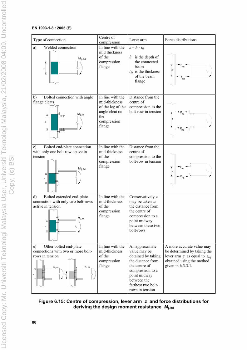
EN 1993-1-8 : 2005 (E)
86
Type of connectionCentre of compression
Lever arm Force distributions
a) Welded connection In line with the mid thickness of the compression flange
z = h - tfb
h is the depth of the connected beam
tfb is the thickness of the beam flange
b) Bolted connection with angle flange cleats
In line with the mid-thickness of the leg of the angle cleat on thecompression flange
Distance from the centre of compression to the bolt-row in tension
c) Bolted end-plate connection with only one bolt-row active in tension
In line with the mid-thickness of the compression flange
Distance from the centre of compression to the bolt-row in tension
d) Bolted extended end-plate connection with only two bolt-rows active in tension
In line with the mid-thickness of the compression flange
Conservatively z may be taken as the distance from the centre of compression to a point midway between these two bolt-rows
e) Other bolted end-plate connections with two or more bolt-rows in tension
In line with the mid-thickness of the compression flange
An approximate value may be obtained by taking the distance from the centre of compression to a point midway between the farthest two bolt-rows in tension
A more accurate value may be determined by taking the lever arm z as equal to zeq
obtained using the method given in 6.3.3.1.
Figure 6.15: Centre of compression, lever arm z and force distributions for deriving the design moment resistance Mj,Rd
Lice
nsed
Cop
y: M
r. U
nive
rsiti
Tek
nolo
gi M
alay
sia
Use
r, U
nive
rsiti
Tek
nolo
gi M
alay
sia,
21/
02/2
008
04:0
9, U
ncon
trol
led
Cop
y, (
c) B
SI
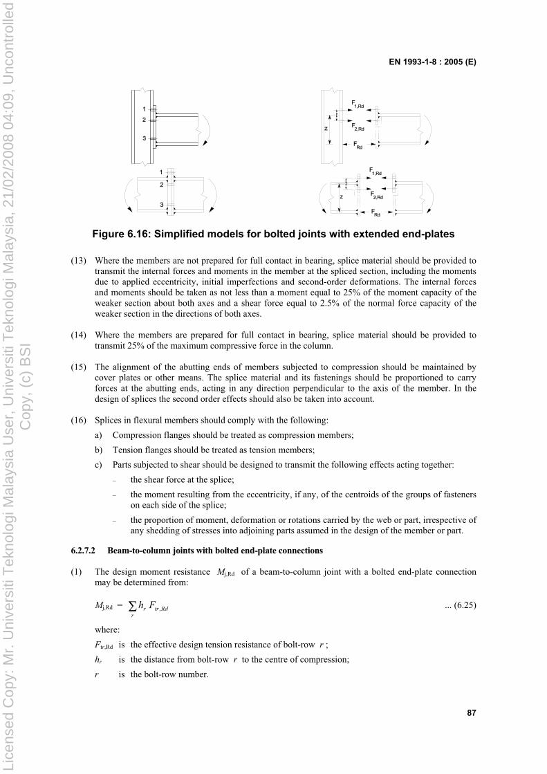
EN 1993-1-8 : 2005 (E)
87
Figure 6.16: Simplified models for bolted joints with extended end-plates
(13) Where the members are not prepared for full contact in bearing, splice material should be provided to transmit the internal forces and moments in the member at the spliced section, including the moments due to applied eccentricity, initial imperfections and second-order deformations. The internal forces and moments should be taken as not less than a moment equal to 25% of the moment capacity of the weaker section about both axes and a shear force equal to 2.5% of the normal force capacity of the weaker section in the directions of both axes.
(14) Where the members are prepared for full contact in bearing, splice material should be provided to transmit 25% of the maximum compressive force in the column.
(15) The alignment of the abutting ends of members subjected to compression should be maintained by cover plates or other means. The splice material and its fastenings should be proportioned to carry forces at the abutting ends, acting in any direction perpendicular to the axis of the member. In the design of splices the second order effects should also be taken into account.
(16) Splices in flexural members should comply with the following:
a) Compression flanges should be treated as compression members;
b) Tension flanges should be treated as tension members;
c) Parts subjected to shear should be designed to transmit the following effects acting together:
– the shear force at the splice;
– the moment resulting from the eccentricity, if any, of the centroids of the groups of fasteners on each side of the splice;
– the proportion of moment, deformation or rotations carried by the web or part, irrespective of any shedding of stresses into adjoining parts assumed in the design of the member or part.
6.2.7.2 Beam-to-column joints with bolted end-plate connections
(1) The design moment resistance Mj,Rd of a beam-to-column joint with a bolted end-plate connection may be determined from:
Mj,Rd = Rdtrrr
Fh , ... (6.25)
where:
Ftr,Rd is the effective design tension resistance of bolt-row r ;
hr is the distance from bolt-row r to the centre of compression;
r is the bolt-row number.
Lice
nsed
Cop
y: M
r. U
nive
rsiti
Tek
nolo
gi M
alay
sia
Use
r, U
nive
rsiti
Tek
nolo
gi M
alay
sia,
21/
02/2
008
04:0
9, U
ncon
trol
led
Cop
y, (
c) B
SI
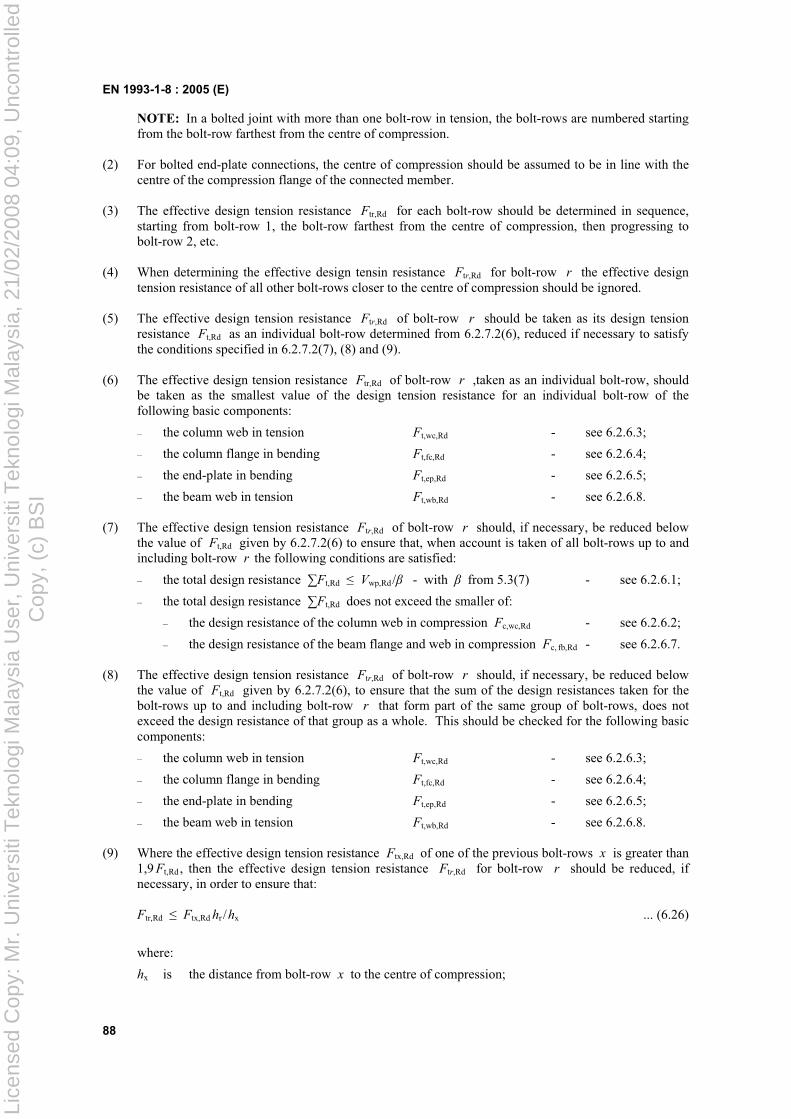
EN 1993-1-8 : 2005 (E)
88
NOTE: In a bolted joint with more than one bolt-row in tension, the bolt-rows are numbered starting from the bolt-row farthest from the centre of compression.
(2) For bolted end-plate connections, the centre of compression should be assumed to be in line with the centre of the compression flange of the connected member.
(3) The effective design tension resistance Ftr,Rd for each bolt-row should be determined in sequence, starting from bolt-row 1, the bolt-row farthest from the centre of compression, then progressing to bolt-row 2, etc.
(4) When determining the effective design tensin resistance Ftr,Rd for bolt-row r the effective design tension resistance of all other bolt-rows closer to the centre of compression should be ignored.
(5) The effective design tension resistance Ftr,Rd of bolt-row r should be taken as its design tension resistance Ft,Rd as an individual bolt-row determined from 6.2.7.2(6), reduced if necessary to satisfy the conditions specified in 6.2.7.2(7), (8) and (9).
(6) The effective design tension resistance Ftr,Rd of bolt-row r ,taken as an individual bolt-row, should be taken as the smallest value of the design tension resistance for an individual bolt-row of the following basic components:
– the column web in tension Ft,wc,Rd - see 6.2.6.3;
– the column flange in bending Ft,fc,Rd - see 6.2.6.4;
– the end-plate in bending Ft,ep,Rd - see 6.2.6.5;
– the beam web in tension Ft,wb,Rd - see 6.2.6.8.
(7) The effective design tension resistance Ftr,Rd of bolt-row r should, if necessary, be reduced below the value of Ft,Rd given by 6.2.7.2(6) to ensure that, when account is taken of all bolt-rows up to and including bolt-row r the following conditions are satisfied:
– the total design resistance Ft,Rd Vwp,Rd/ - with from 5.3(7) - see 6.2.6.1;
– the total design resistance Ft,Rd does not exceed the smaller of:
– the design resistance of the column web in compression Fc,wc,Rd - see 6.2.6.2;
– the design resistance of the beam flange and web in compression Fc, fb,Rd - see 6.2.6.7.
(8) The effective design tension resistance Ftr,Rd of bolt-row r should, if necessary, be reduced below the value of Ft,Rd given by 6.2.7.2(6), to ensure that the sum of the design resistances taken for the bolt-rows up to and including bolt-row r that form part of the same group of bolt-rows, does not exceed the design resistance of that group as a whole. This should be checked for the following basic components:
– the column web in tension Ft,wc,Rd - see 6.2.6.3;
– the column flange in bending Ft,fc,Rd - see 6.2.6.4;
– the end-plate in bending Ft,ep,Rd - see 6.2.6.5;
– the beam web in tension Ft,wb,Rd - see 6.2.6.8.
(9) Where the effective design tension resistance Ftx,Rd of one of the previous bolt-rows x is greater than 1,9 Ft,Rd , then the effective design tension resistance Ftr,Rd for bolt-row r should be reduced, if necessary, in order to ensure that:
Ftr,Rd Ftx,Rd hr /hx ... (6.26)
where:
hx is the distance from bolt-row x to the centre of compression;
Lice
nsed
Cop
y: M
r. U
nive
rsiti
Tek
nolo
gi M
alay
sia
Use
r, U
nive
rsiti
Tek
nolo
gi M
alay
sia,
21/
02/2
008
04:0
9, U
ncon
trol
led
Cop
y, (
c) B
SI
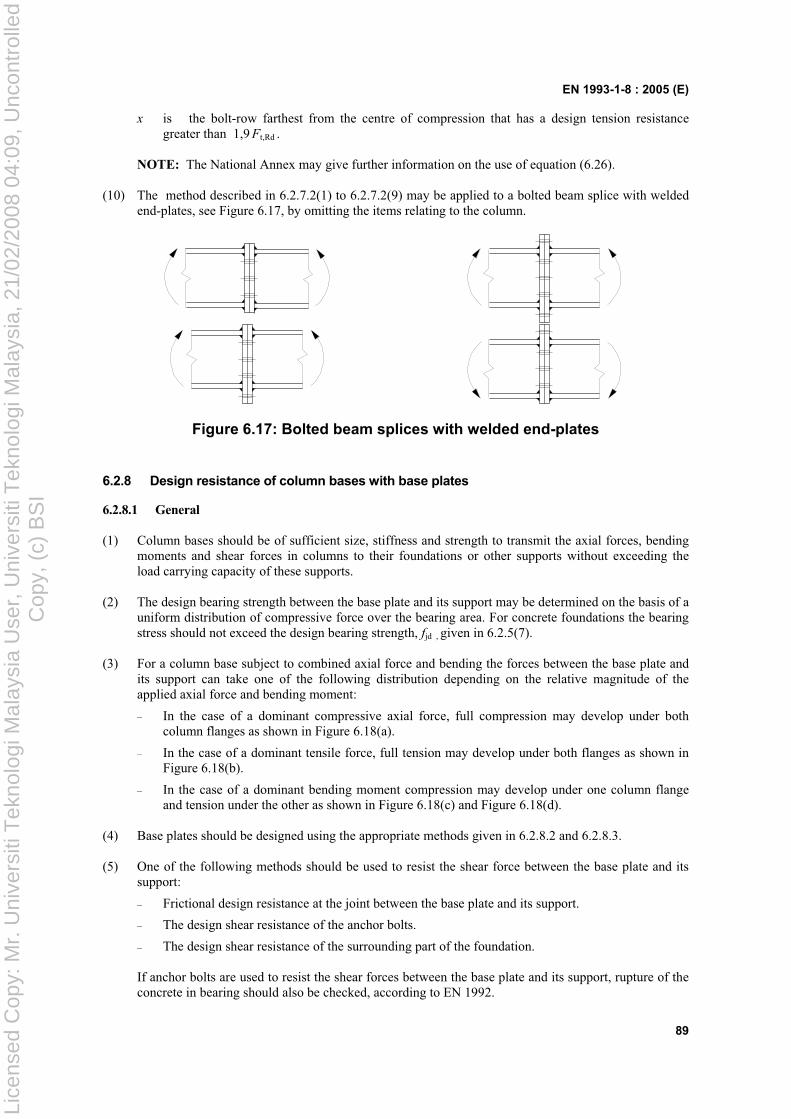
EN 1993-1-8 : 2005 (E)
89
x is the bolt-row farthest from the centre of compression that has a design tension resistance greater than 1,9 Ft,Rd .
NOTE: The National Annex may give further information on the use of equation (6.26).
(10) The method described in 6.2.7.2(1) to 6.2.7.2(9) may be applied to a bolted beam splice with welded end-plates, see Figure 6.17, by omitting the items relating to the column.
Figure 6.17: Bolted beam splices with welded end-plates
6.2.8 Design resistance of column bases with base plates
6.2.8.1 General
(1) Column bases should be of sufficient size, stiffness and strength to transmit the axial forces, bending moments and shear forces in columns to their foundations or other supports without exceeding the load carrying capacity of these supports.
(2) The design bearing strength between the base plate and its support may be determined on the basis of a uniform distribution of compressive force over the bearing area. For concrete foundations the bearing stress should not exceed the design bearing strength, fjd , given in 6.2.5(7).
(3) For a column base subject to combined axial force and bending the forces between the base plate and its support can take one of the following distribution depending on the relative magnitude of the applied axial force and bending moment:
– In the case of a dominant compressive axial force, full compression may develop under both column flanges as shown in Figure 6.18(a).
– In the case of a dominant tensile force, full tension may develop under both flanges as shown in Figure 6.18(b).
– In the case of a dominant bending moment compression may develop under one column flange and tension under the other as shown in Figure 6.18(c) and Figure 6.18(d).
(4) Base plates should be designed using the appropriate methods given in 6.2.8.2 and 6.2.8.3.
(5) One of the following methods should be used to resist the shear force between the base plate and its support:
– Frictional design resistance at the joint between the base plate and its support.
– The design shear resistance of the anchor bolts.
– The design shear resistance of the surrounding part of the foundation.
If anchor bolts are used to resist the shear forces between the base plate and its support, rupture of the concrete in bearing should also be checked, according to EN 1992.
Lice
nsed
Cop
y: M
r. U
nive
rsiti
Tek
nolo
gi M
alay
sia
Use
r, U
nive
rsiti
Tek
nolo
gi M
alay
sia,
21/
02/2
008
04:0
9, U
ncon
trol
led
Cop
y, (
c) B
SI
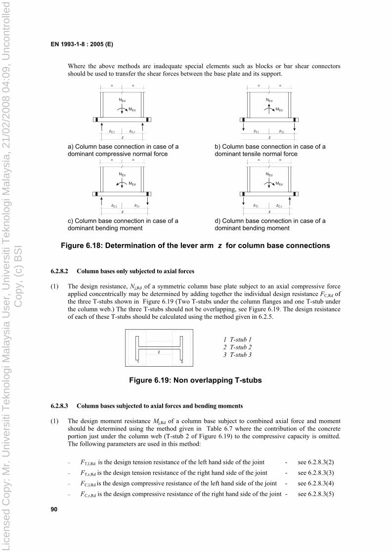
EN 1993-1-8 : 2005 (E)
90
Where the above methods are inadequate special elements such as blocks or bar shear connectors should be used to transfer the shear forces between the base plate and its support.
MEd
zC,l
z
= =
zC,r
NEd
MEd
zT,l
z
zT,r
NEd
= =
a) Column base connection in case of a dominant compressive normal force
b) Column base connection in case of a dominant tensile normal force
MEd
zC,l
z
= =
zT,r
NEd
MEd
zT,l
z
= =
zC,r
NEd
c) Column base connection in case of a dominant bending moment
d) Column base connection in case of a dominant bending moment
Figure 6.18: Determination of the lever arm z for column base connections
6.2.8.2 Column bases only subjected to axial forces
(1) The design resistance, Nj,Rd ,of a symmetric column base plate subject to an axial compressive force applied concentrically may be determined by adding together the individual design resistance FC,Rd of the three T-stubs shown in Figure 6.19 (Two T-stubs under the column flanges and one T-stub under the column web.) The three T-stubs should not be overlapping, see Figure 6.19. The design resistance of each of these T-stubs should be calculated using the method given in 6.2.5.
1 3
2
1 T-stub 1
2 T-stub 2
3 T-stub 3
Figure 6.19: Non overlapping T-stubs
6.2.8.3 Column bases subjected to axial forces and bending moments
(1) The design moment resistance Mj,Rd of a column base subject to combined axial force and moment should be determined using the method given in Table 6.7 where the contribution of the concrete portion just under the column web (T-stub 2 of Figure 6.19) to the compressive capacity is omitted. The following parameters are used in this method:
– FT,l,Rd is the design tension resistance of the left hand side of the joint - see 6.2.8.3(2)
– FT,r,Rd is the design tension resistance of the right hand side of the joint - see 6.2.8.3(3)
– FC,l,Rd is the design compressive resistance of the left hand side of the joint - see 6.2.8.3(4)
– FC,r,Rd is the design compressive resistance of the right hand side of the joint - see 6.2.8.3(5)
Lice
nsed
Cop
y: M
r. U
nive
rsiti
Tek
nolo
gi M
alay
sia
Use
r, U
nive
rsiti
Tek
nolo
gi M
alay
sia,
21/
02/2
008
04:0
9, U
ncon
trol
led
Cop
y, (
c) B
SI
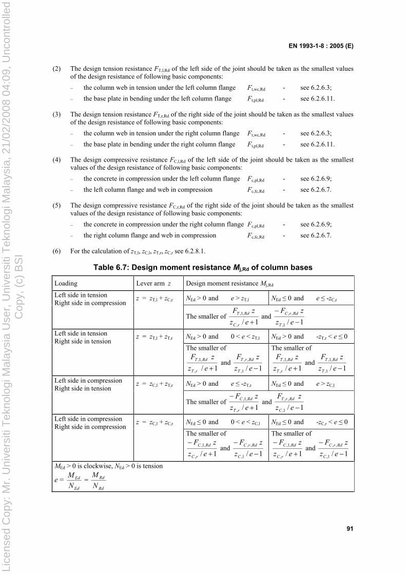
EN 1993-1-8 : 2005 (E)
91
(2) The design tension resistance FT,l,Rd of the left side of the joint should be taken as the smallest values of the design resistance of following basic components:
– the column web in tension under the left column flange Ft,wc,Rd - see 6.2.6.3;
– the base plate in bending under the left column flange Ft,pl,Rd - see 6.2.6.11.
(3) The design tension resistance FT,r,Rd of the right side of the joint should be taken as the smallest values of the design resistance of following basic components:
– the column web in tension under the right column flange Ft,wc,Rd - see 6.2.6.3;
– the base plate in bending under the right column flange Ft,pl,Rd - see 6.2.6.11.
(4) The design compressive resistance FC,l,Rd of the left side of the joint should be taken as the smallest values of the design resistance of following basic components:
– the concrete in compression under the left column flange Fc,pl,Rd - see 6.2.6.9;
– the left column flange and web in compression Fc,fc,Rd - see 6.2.6.7.
(5) The design compressive resistance FC,r,Rd of the right side of the joint should be taken as the smallest values of the design resistance of following basic components:
– the concrete in compression under the right column flange Fc,pl,Rd - see 6.2.6.9;
– the right column flange and web in compression Fc,fc,Rd - see 6.2.6.7.
(6) For the calculation of zT,l, zC,l, zT,r, zC,r see 6.2.8.1.
Table 6.7: Design moment resistance Mj,Rd of column bases
Loading Lever arm z Design moment resistance Mj,Rd
z = zT,l + zC,r NEd > 0 and e > zT,l NEd 0 and e -zC,rLeft side in tension Right side in compression
The smaller of 1/,
,1,
ez
zF
rC
RdT and 1/1,
,,
ez
zF
T
RdrC
z = zT,l + zT,r NEd > 0 and 0 < e < zT,l NEd > 0 and -zT,r < e 0Left side in tension Right side in tension
The smaller of
1/,
,1,
ez
zF
rT
RdT and 1/1,
,,
ez
zF
T
RdrT
The smaller of
1/,
,1,
ez
zF
rT
RdT and 1/1,
,1,
ez
zF
T
RdT
z = zC,l + zT,r NEd > 0 and e -zT,r NEd 0 and e > zC,lLeft side in compression Right side in tension
The smaller of 1/,
,1,
ez
zF
rT
RdC and 1/1,
,,
ez
zF
C
RdrT
z = zC,l + zC,r NEd 0 and 0 < e < zC,l NEd 0 and -zC,r < e 0Left side in compression Right side in compression
The smaller of
1/,
,1,
ez
zF
rC
RdC and 1/1,
,,
ez
zF
C
RdrC
The smaller of
1/,
,1,
ez
zF
rC
RdC and 1/1,
,,
ez
zF
C
RdrC
MEd > 0 is clockwise, NEd > 0 is tension
e = Ed
Ed
N
M =
Rd
Rd
N
M
Lice
nsed
Cop
y: M
r. U
nive
rsiti
Tek
nolo
gi M
alay
sia
Use
r, U
nive
rsiti
Tek
nolo
gi M
alay
sia,
21/
02/2
008
04:0
9, U
ncon
trol
led
Cop
y, (
c) B
SI
EN 1993-1-8 : 2005 (E)
92
6.3 Rotational stiffness
6.3.1 Basic model
(1) The rotational stiffness of a joint should be determined from the flexibilities of its basic components, each represented by an elastic stiffness coefficient ki obtained from 6.3.2.
NOTE: These elastic stiffness coefficients are for general application.
(2) For a bolted end-plate joint with more than one row of bolts in tension, the stiffness coefficients ki for the related basic components should be combined. For beam-to-column joints and beam splices a method is given in 6.3.3 and for column bases a method is given in 6.3.4.
(3) In a bolted end plate joint with more than one bolt-row in tension, as a simplification the contribution of any bolt-row may be neglected, provided that the contributions of all other bolt-rows closer to the centre of compression are also neglected. The number of bolt-rows retained need not necessarily be the same as for the determination of the design moment resistance.
(4) Provided that the axial force NEd in the connected member does not exceed 5% of the design resistance Np ,Rd of its cross-section, the rotational stiffness Sj of a beam-to-column joint or beam splice, for a moment Mj,Ed less than the design moment resistance Mj,Rd of the joint, may be obtained with sufficient accuracy from:
Sj =
i ik
Ez
1
2
... (6.27)
where:
ki is the stiffness coefficient for basic joint component i ;
z is the lever arm, see 6.2.7;
µ is the stiffness ratio Sj,ini / Sj , see 6.3.1(6).
NOTE: The initial rotational stiffness Sj,ini of the joint is given by expression (6.27) with µ = 1,0.
(5) The rotational stiffness Sj of a column base, for a moment Mj,Ed less than the design moment resistance Mj,Rd of the joint, may be obtained with sufficient accuracy from 6.3.4.
(6) The stiffness ratio µ should be determined from the following:
– if Mj,Ed 2/3 Mj,Rd: µ = 1 ... (6.28a)
– if 2/3 Mj,Rd < Mj,Ed Mj,Rd :
µ = )/5,1( ,, RdjEdj MM ... (6.28b)
in which the coefficient is obtained from Table 6.8.
Lice
nsed
Cop
y: M
r. U
nive
rsiti
Tek
nolo
gi M
alay
sia
Use
r, U
nive
rsiti
Tek
nolo
gi M
alay
sia,
21/
02/2
008
04:0
9, U
ncon
trol
led
Cop
y, (
c) B
SI
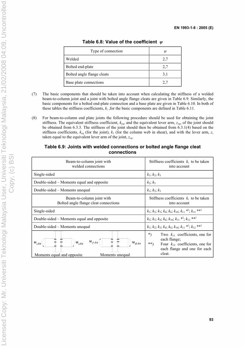
EN 1993-1-8 : 2005 (E)
93
Table 6.8: Value of the coefficient
Type of connection
Welded 2,7
Bolted end-plate 2,7
Bolted angle flange cleats 3,1
Base plate connections 2,7
(7) The basic components that should be taken into account when calculating the stiffness of a welded beam-to-column joint and a joint with bolted angle flange cleats are given in Table 6.9. Similarly, the basic components for a bolted end-plate connection and a base plate are given in Table 6.10. In both of these tables the stiffness coefficients, ki ,for the basic components are defined in Table 6.11.
(8) For beam-to-column end plate joints the following procedure should be used for obtaining the joint stiffness. The equivalent stiffness coefficient, keq, and the equivalent lever arm, zeq, of the joint should be obtained from 6.3.3. The stiffness of the joint should then be obtained from 6.3.1(4) based on the stiffness coefficients, keq (for the joint), k1 (for the column web in shear), and with the lever arm, z,taken equal to the equivalent lever arm of the joint, zeq.
Table 6.9: Joints with welded connections or bolted angle flange cleat connections
Beam-to-column joint with welded connections
Stiffness coefficients ki to be taken into account
Single-sided k1; k2; k3
Double-sided – Moments equal and opposite k2; k3
Double-sided – Moments unequal k1; k2; k3
Beam-to-column joint with Bolted angle flange cleat connections
Stiffness coefficients ki to be taken into account
Single-sided k1; k2; k3; k4; k6; k10; k11 *); k12 **)
Double-sided – Moments equal and opposite k2; k3; k4; k6; k10; k11 *); k12 **)
Double-sided – Moments unequal k1; k2; k3; k4; k6; k10; k11 *); k12 **)
Moments equal and opposite Moments unequal
*) Two k11 coefficients, one for each flange;
**) Four k12 coefficients, one for each flange and one for each cleat.
Lice
nsed
Cop
y: M
r. U
nive
rsiti
Tek
nolo
gi M
alay
sia
Use
r, U
nive
rsiti
Tek
nolo
gi M
alay
sia,
21/
02/2
008
04:0
9, U
ncon
trol
led
Cop
y, (
c) B
SI
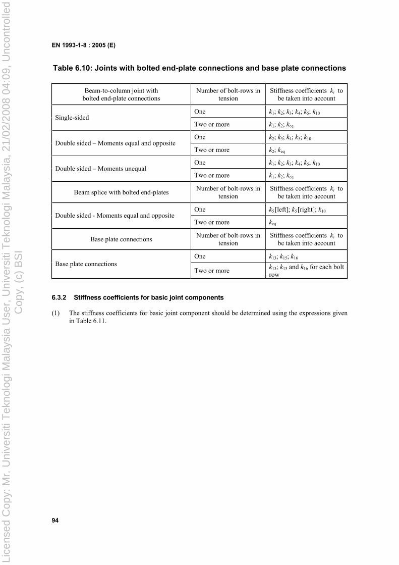
EN 1993-1-8 : 2005 (E)
94
Table 6.10: Joints with bolted end-plate connections and base plate connections
Beam-to-column joint with bolted end-plate connections
Number of bolt-rows in tension
Stiffness coefficients ki to be taken into account
One k1; k2; k3; k4; k5; k10Single-sided
Two or more k1; k2; keq
One k2; k3; k4; k5; k10Double sided – Moments equal and opposite
Two or more k2; keq
One k1; k2; k3; k4; k5; k10Double sided – Moments unequal
Two or more k1; k2; keq
Beam splice with bolted end-platesNumber of bolt-rows in
tensionStiffness coefficients ki to
be taken into account
One k5[left]; k5[right]; k10Double sided - Moments equal and opposite
Two or more keq
Base plate connectionsNumber of bolt-rows in
tensionStiffness coefficients ki to
be taken into account
One k13; k15; k16
Base plate connectionsTwo or more
k13; k15 and k16 for each bolt row
6.3.2 Stiffness coefficients for basic joint components
(1) The stiffness coefficients for basic joint component should be determined using the expressions given in Table 6.11.
Lice
nsed
Cop
y: M
r. U
nive
rsiti
Tek
nolo
gi M
alay
sia
Use
r, U
nive
rsiti
Tek
nolo
gi M
alay
sia,
21/
02/2
008
04:0
9, U
ncon
trol
led
Cop
y, (
c) B
SI
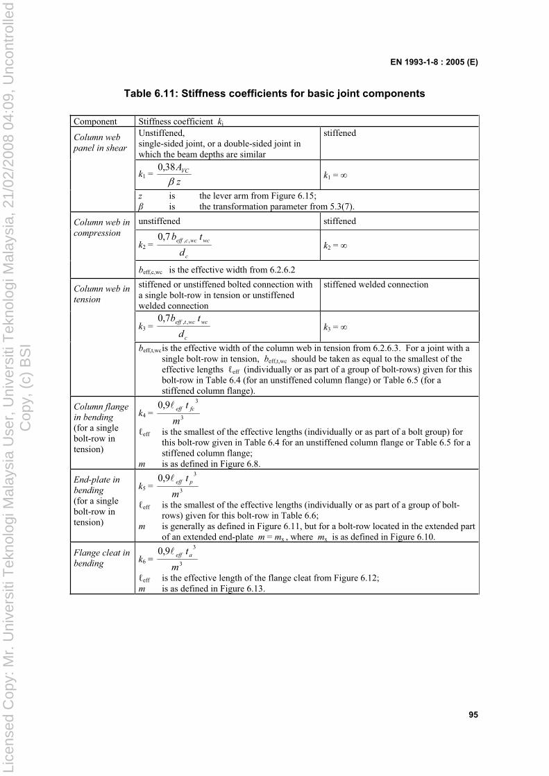
EN 1993-1-8 : 2005 (E)
95
Table 6.11: Stiffness coefficients for basic joint components
Component Stiffness coefficient ki
Unstiffened, single-sided joint, or a double-sided joint in which the beam depths are similar
stiffened
k1 = z
AVC38,0k1 =
Column web
panel in shear
z is the lever arm from Figure 6.15; is the transformation parameter from 5.3(7).
unstiffened stiffened
k2 = c
wcwcceff
d
tb ,,7,0k2 =
Column web in
compression
beff,c,wc is the effective width from 6.2.6.2
stiffened or unstiffened bolted connection with a single bolt-row in tension or unstiffened welded connection
stiffened welded connection
k3 = c
wcwcteff
d
tb ,,7,0k3 =
Column web in
tension
beff,t,wc is the effective width of the column web in tension from 6.2.6.3. For a joint with a single bolt-row in tension, beff,t,wc should be taken as equal to the smallest of the effective lengths eff (individually or as part of a group of bolt-rows) given for this bolt-row in Table 6.4 (for an unstiffened column flange) or Table 6.5 (for a stiffened column flange).
Column flange in bending
(for a single bolt-row in tension)
k4 = 3
39,0
m
t fceff
eff is the smallest of the effective lengths (individually or as part of a bolt group) for this bolt-row given in Table 6.4 for an unstiffened column flange or Table 6.5 for a stiffened column flange;
m is as defined in Figure 6.8.
End-plate in
bending
(for a single bolt-row in tension)
k5 = 3
39,0
m
t peff
eff is the smallest of the effective lengths (individually or as part of a group of bolt-rows) given for this bolt-row in Table 6.6;
m is generally as defined in Figure 6.11, but for a bolt-row located in the extended part of an extended end-plate m = mx , where mx is as defined in Figure 6.10.
Flange cleat in bending k6 =
3
39,0
m
taeff
eff is the effective length of the flange cleat from Figure 6.12; m is as defined in Figure 6.13.
Lice
nsed
Cop
y: M
r. U
nive
rsiti
Tek
nolo
gi M
alay
sia
Use
r, U
nive
rsiti
Tek
nolo
gi M
alay
sia,
21/
02/2
008
04:0
9, U
ncon
trol
led
Cop
y, (
c) B
SI
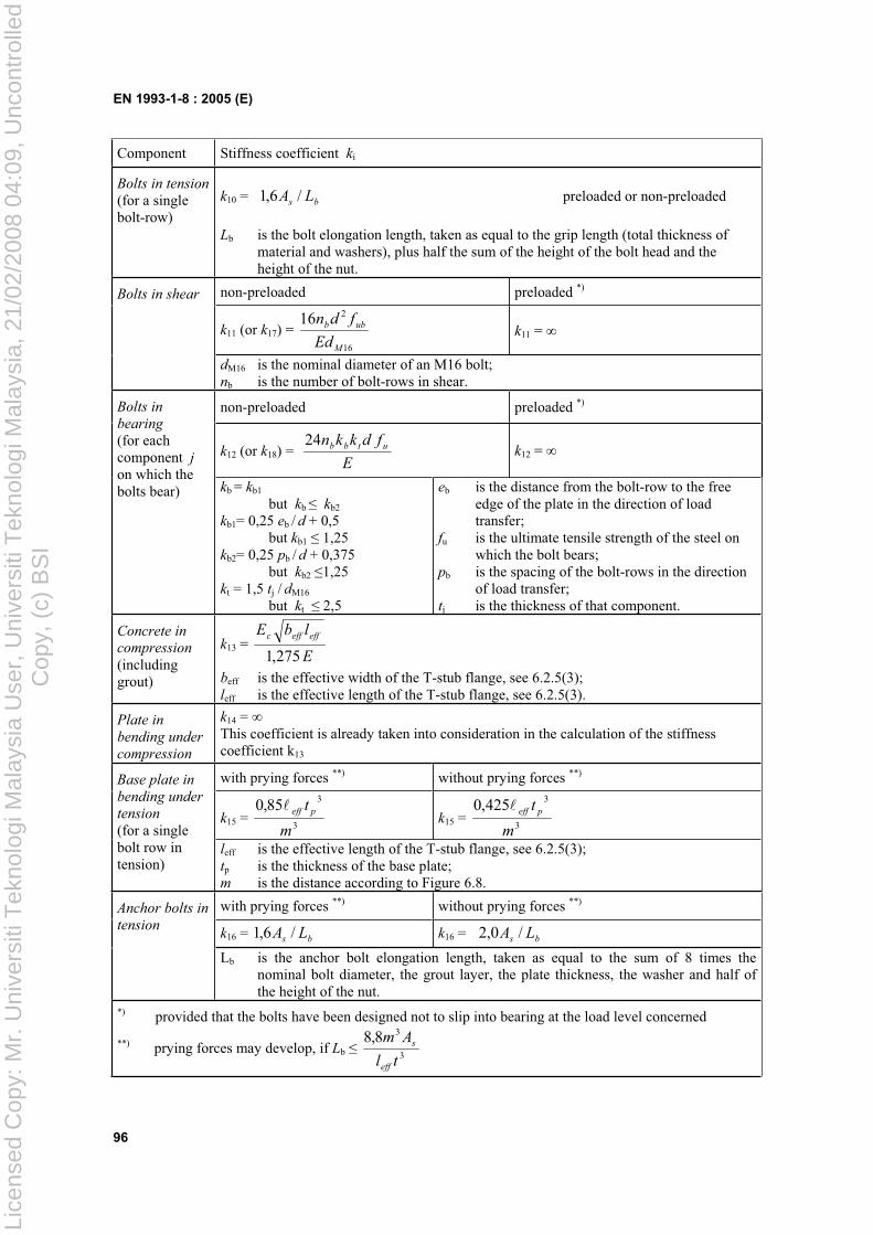
EN 1993-1-8 : 2005 (E)
96
Component Stiffness coefficient ki
Bolts in tension
(for a single bolt-row)
k10 = bs LA /6,1 preloaded or non-preloaded
Lb is the bolt elongation length, taken as equal to the grip length (total thickness of material and washers), plus half the sum of the height of the bolt head and the height of the nut.
non-preloaded preloaded *)
k11 (or k17) = 16
216
M
ubb
Ed
fdnk11 =
Bolts in shear
dM16 is the nominal diameter of an M16 bolt; nb is the number of bolt-rows in shear.
non-preloaded preloaded *)
k12 (or k18) = E
fdkkn utbb24k12 =
Bolts in
bearing
(for each component jon which the bolts bear) kb = kb1
but kb kb2
kb1= 0,25 eb / d + 0,5 but kb1 1,25 kb2= 0,25 pb / d + 0,375 but kb2 1,25 kt = 1,5 tj / dM16
but kt 2,5
eb is the distance from the bolt-row to the free edge of the plate in the direction of load transfer;
fu is the ultimate tensile strength of the steel on which the bolt bears;
pb is the spacing of the bolt-rows in the direction of load transfer;
tj is the thickness of that component.
Concrete in compression
(including grout)
k13 = E
lbE effeffc
275,1beff is the effective width of the T-stub flange, see 6.2.5(3); leff is the effective length of the T-stub flange, see 6.2.5(3).
Plate in
bending under
compression
k14 = This coefficient is already taken into consideration in the calculation of the stiffness coefficient k13
with prying forces **) without prying forces **)
k15 = 3
385,0
m
t peffk15 =
3
3425,0
m
t peff
Base plate in
bending under tension
(for a single bolt row in tension)
leff is the effective length of the T-stub flange, see 6.2.5(3); tp is the thickness of the base plate; m is the distance according to Figure 6.8.
with prying forces **) without prying forces **)
k16 = bs LA /6,1 k16 = bs LA /0,2
Anchor bolts in
tension
Lb is the anchor bolt elongation length, taken as equal to the sum of 8 times the nominal bolt diameter, the grout layer, the plate thickness, the washer and half of the height of the nut.
*) provided that the bolts have been designed not to slip into bearing at the load level concerned
**) prying forces may develop, if Lb 3
38,8
tl
Am
eff
s
Lice
nsed
Cop
y: M
r. U
nive
rsiti
Tek
nolo
gi M
alay
sia
Use
r, U
nive
rsiti
Tek
nolo
gi M
alay
sia,
21/
02/2
008
04:0
9, U
ncon
trol
led
Cop
y, (
c) B
SI
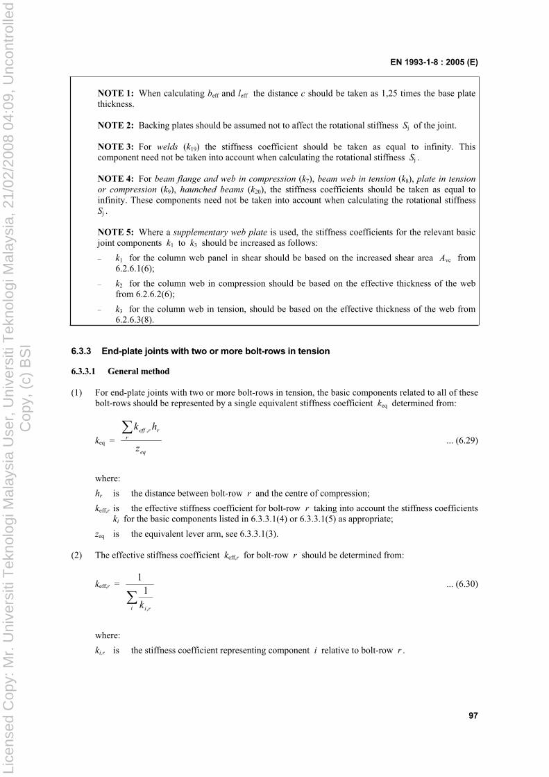
EN 1993-1-8 : 2005 (E)
97
NOTE 1: When calculating beff and leff the distance c should be taken as 1,25 times the base plate thickness.
NOTE 2: Backing plates should be assumed not to affect the rotational stiffness Sj of the joint.
NOTE 3: For welds (k19) the stiffness coefficient should be taken as equal to infinity. This component need not be taken into account when calculating the rotational stiffness Sj .
NOTE 4: For beam flange and web in compression (k7), beam web in tension (k8), plate in tension
or compression (k9), haunched beams (k20), the stiffness coefficients should be taken as equal to infinity. These components need not be taken into account when calculating the rotational stiffness Sj .
NOTE 5: Where a supplementary web plate is used, the stiffness coefficients for the relevant basic joint components k1 to k3 should be increased as follows:
– k1 for the column web panel in shear should be based on the increased shear area Avc from 6.2.6.1(6);
– k2 for the column web in compression should be based on the effective thickness of the web from 6.2.6.2(6);
– k3 for the column web in tension, should be based on the effective thickness of the web from 6.2.6.3(8).
6.3.3 End-plate joints with two or more bolt-rows in tension
6.3.3.1 General method
(1) For end-plate joints with two or more bolt-rows in tension, the basic components related to all of these bolt-rows should be represented by a single equivalent stiffness coefficient keq determined from:
keq = eq
r
rreff
z
hk ,
... (6.29)
where:
hr is the distance between bolt-row r and the centre of compression;
keff,r is the effective stiffness coefficient for bolt-row r taking into account the stiffness coefficients ki for the basic components listed in 6.3.3.1(4) or 6.3.3.1(5) as appropriate;
zeq is the equivalent lever arm, see 6.3.3.1(3).
(2) The effective stiffness coefficient keff,r for bolt-row r should be determined from:
keff,r =
i rik ,
11
... (6.30)
where:
ki,r is the stiffness coefficient representing component i relative to bolt-row r .
Lice
nsed
Cop
y: M
r. U
nive
rsiti
Tek
nolo
gi M
alay
sia
Use
r, U
nive
rsiti
Tek
nolo
gi M
alay
sia,
21/
02/2
008
04:0
9, U
ncon
trol
led
Cop
y, (
c) B
SI
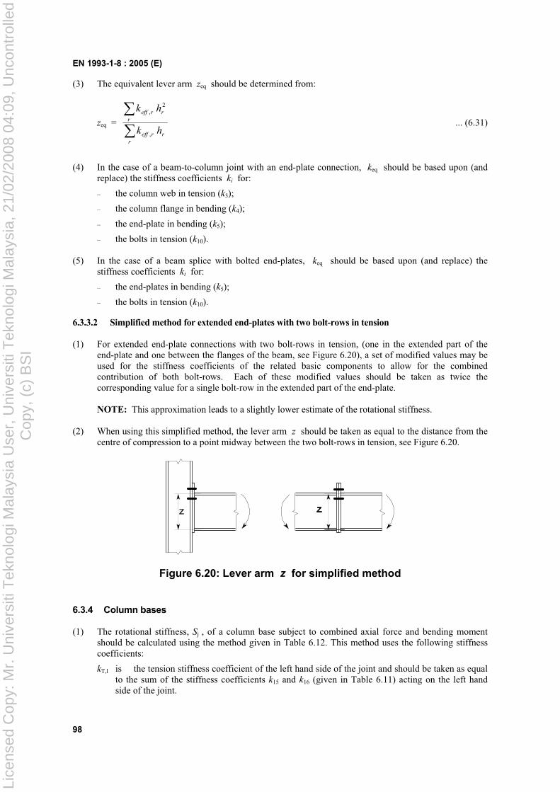
EN 1993-1-8 : 2005 (E)
98
(3) The equivalent lever arm zeq should be determined from:
zeq =
r
rreff
r
rreff
hk
hk
,
2,
... (6.31)
(4) In the case of a beam-to-column joint with an end-plate connection, keq should be based upon (and replace) the stiffness coefficients ki for:
– the column web in tension (k3);
– the column flange in bending (k4);
– the end-plate in bending (k5);
– the bolts in tension (k10).
(5) In the case of a beam splice with bolted end-plates, keq should be based upon (and replace) the stiffness coefficients ki for:
– the end-plates in bending (k5);
– the bolts in tension (k10).
6.3.3.2 Simplified method for extended end-plates with two bolt-rows in tension
(1) For extended end-plate connections with two bolt-rows in tension, (one in the extended part of the end-plate and one between the flanges of the beam, see Figure 6.20), a set of modified values may be used for the stiffness coefficients of the related basic components to allow for the combined contribution of both bolt-rows. Each of these modified values should be taken as twice the corresponding value for a single bolt-row in the extended part of the end-plate.
NOTE: This approximation leads to a slightly lower estimate of the rotational stiffness.
(2) When using this simplified method, the lever arm z should be taken as equal to the distance from the centre of compression to a point midway between the two bolt-rows in tension, see Figure 6.20.
Figure 6.20: Lever arm z for simplified method
6.3.4 Column bases
(1) The rotational stiffness, Sj , of a column base subject to combined axial force and bending moment should be calculated using the method given in Table 6.12. This method uses the following stiffness coefficients:
kT,l is the tension stiffness coefficient of the left hand side of the joint and should be taken as equal to the sum of the stiffness coefficients k15 and k16 (given in Table 6.11) acting on the left hand side of the joint.
Lice
nsed
Cop
y: M
r. U
nive
rsiti
Tek
nolo
gi M
alay
sia
Use
r, U
nive
rsiti
Tek
nolo
gi M
alay
sia,
21/
02/2
008
04:0
9, U
ncon
trol
led
Cop
y, (
c) B
SI
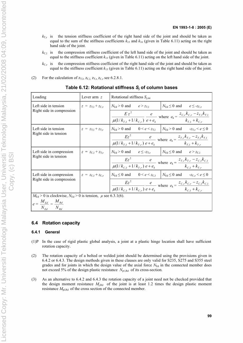
EN 1993-1-8 : 2005 (E)
99
kT,r is the tension stiffness coefficient of the right hand side of the joint and should be taken as equal to the sum of the stiffness coefficients k15 and k16 (given in Table 6.11) acting on the right hand side of the joint.
kC,l is the compression stiffness coefficient of the left hand side of the joint and should be taken as equal to the stiffness coefficient k13 (given in Table 6.11) acting on the left hand side of the joint.
kC,r is the compression stiffness coefficient of the right hand side of the joint and should be taken as equal to the stiffness coefficient k13 (given in Table 6.11) acting on the right hand side of the joint.
(2) For the calculation of zT,l, zC,l, zT,r, zC,r see 6.2.8.1.
Table 6.12: Rotational stiffness Sj of column bases
Loading Lever arm z Rotational stiffness Sj,ini
z = zT,l + zC,r NEd > 0 and e > zT,l NEd 0 and e -zC,rLeft side in tension Right side in compression
krCT ee
e
kk
zE
)/1/1( ,1,
2
where ek = rCT
TTrCrC
kk
kzkz
,1,
1,1,,,
z = zT,l + zT,r NEd > 0 and 0 < e < zT,l NEd > 0 and -zT,r < e 0 Left side in tension Right side in tension
krTT ee
e
kk
Ez
)/1/1( ,1,
2
where ek = rTT
TTrTrT
kk
kzkz
,1,
1,1,,,
z = zC,l + zT,r NEd > 0 and e -zT,r NEd 0 and e > zC,lLeft side in compression Right side in tension
krTC ee
e
kk
Ez
)/1/1( ,1,
2
where ek = rTC
CCrTrT
kk
kzkz
,1,
1,1,,,
z = zC,l + zC,r NEd 0 and 0 < e < zC,l NEd 0 and -zC,r < e 0 Left side in compression Right side in compression
krCC ee
e
kk
Ez
)/1/1( ,1,
2
where ek = rCC
CCrCrC
kk
kzkz
,1,
1,1,,,
MEd > 0 is clockwise, NEd > 0 is tension, µ see 6.3.1(6).
e = Ed
Ed
N
M =
Rd
Rd
N
M
6.4 Rotation capacity
6.4.1 General
(1)P In the case of rigid plastic global analysis, a joint at a plastic hinge location shall have sufficientrotation capacity.
(2) The rotation capacity of a bolted or welded joint should be determined using the provisions given in 6.4.2 or 6.4.3. The design methods given in these clauses are only valid for S235, S275 and S355 steel grades and for joints in which the design value of the axial force NEd in the connected member does not exceed 5% of the design plastic resistance Np ,Rd of its cross-section.
(3) As an alternative to 6.4.2 and 6.4.3 the rotation capacity of a joint need not be checked provided that the design moment resistance Mj,Rd of the joint is at least 1.2 times the design plastic moment resistance Mpl,Rd of the cross section of the connected member.
Lice
nsed
Cop
y: M
r. U
nive
rsiti
Tek
nolo
gi M
alay
sia
Use
r, U
nive
rsiti
Tek
nolo
gi M
alay
sia,
21/
02/2
008
04:0
9, U
ncon
trol
led
Cop
y, (
c) B
SI
EN 1993-1-8 : 2005 (E)
100
(4) In cases not covered by 6.4.2 and 6.4.3 the rotation capacity may be determined by testing in accordance with EN 1990, Annex D. Alternatively, appropriate calculation models may be used, provided that they are based on the results of tests in accordance with EN 1990.
6.4.2 Bolted joints
(1) A beam-to-column joint in which the design moment resistance of the joint Mj,Rd is governed by the design resistance of the column web panel in shear, may be assumed to have adequate rotation capacity for plastic global analysis, provided that d/tw 69 .
(2) A joint with either a bolted end-plate or angle flange cleat connection may be assumed to have sufficient rotation capacity for plastic analysis, provided that both of the following conditions are satisfied:
a) the design moment resistance of the joint is governed by the design resistance of either:
– the column flange in bending or
– the beam end-plate or tension flange cleat in bending.
b) the thickness t of either the column flange or the beam end-plate or tension flange cleat (not necessarily the same basic component as in (a)) satisfies:
t yub ffd /36,0 ... (6.32)
where:
fy is the yield strength of the relevant basic component.
(3) A joint with a bolted connection in which the design moment resistance Mj,Rd is governed by the design resistance of its bolts in shear, should not be assumed to have sufficient rotation capacity for plastic global analysis.
6.4.3 Welded Joints
(1) The rotation capacity Cd of a welded beam-to-column connection may be assumed to be not less that the value given by the following expression provided that its column web is stiffened in compression but unstiffened in tension, and its design moment resistance is not governed by the design shear resistance of the column web panel, see 6.4.2(1):
Cd = 0,025 hc /hb ... (6.33)
where:
hb is the depth of the beam;
hc is the depth of the column.
(2) An unstiffened welded beam-to-column joint designed in conformity with the provisions of this section, may be assumed to have a rotation capacity Cd of at least 0,015 radians.
Lice
nsed
Cop
y: M
r. U
nive
rsiti
Tek
nolo
gi M
alay
sia
Use
r, U
nive
rsiti
Tek
nolo
gi M
alay
sia,
21/
02/2
008
04:0
9, U
ncon
trol
led
Cop
y, (
c) B
SI
EN 1993-1-8 : 2005 (E)
101
7 Hollow section joints
7.1 General
7.1.1 Scope
(1) This section gives detailed application rules to determine the static design resistances of uniplanar and multiplanar joints in lattice structures composed of circular, square or rectangular hollow sections, and of uniplanar joints in lattice structures composed of combinations of hollow sections with open sections.
(2) The static design resistances of the joints are expressed in terms of maximum design axial and/or moment resistances for the brace members.
(3) These application rules are valid both for hot finished hollow sections to EN 10210 and for cold formed hollow sections to EN 10219, if the dimensions of the structural hollow sections fulfil the requirements of this section.
(4) For hot finished hollow sections and cold formed hollow sections the nominal yield strength of the end product should not exceed 460 N/mm2. For end products with a nominal yield strength higher than 355 N/mm2 , the static design resistances given in this section should be reduced by a factor 0,9.
(5) The nominal wall thickness of hollow sections should not be less than 2,5 mm.
(6) The nominal wall thickness of a hollow section chord should not be greater than 25 mm unless special measures have been taken to ensure that the through thickness properties of the material will be adequate.
(7) For fatigue assessment see EN 1993-1-9.
(8) The types of joints covered are indicated in Figure 7.1.
7.1.2 Field of application
(1) The application rules for hollow section joints may be used only where all of the conditions given in 7.1.2(2) to 7.1.2(8) are satisfied.
(2) The compression elements of the members should satisfy the requirements for Class 1 or Class 2 given in EN 1993-1-1 for the condition of pure bending.
(3) The angles i between the chords and the brace members, and between adjacent brace members, should satisfy:
i 30°
(4) The ends of members that meet at a joint should be prepared in such a way that their cross-sectional shape is not modified. Flattened end connections and cropped end connections are not covered in this section.
(5) In gap type joints, in order to ensure that the clearance is adequate for forming satisfactory welds, the gap between the brace members should not be less than ( t1 + t2).
(6) In overlap type joints, the overlap should be large enough to ensure that the interconnection of the brace members is sufficient for adequate shear transfer from one brace to the other. In any case the overlap should be at least 25%.
Lice
nsed
Cop
y: M
r. U
nive
rsiti
Tek
nolo
gi M
alay
sia
Use
r, U
nive
rsiti
Tek
nolo
gi M
alay
sia,
21/
02/2
008
04:0
9, U
ncon
trol
led
Cop
y, (
c) B
SI
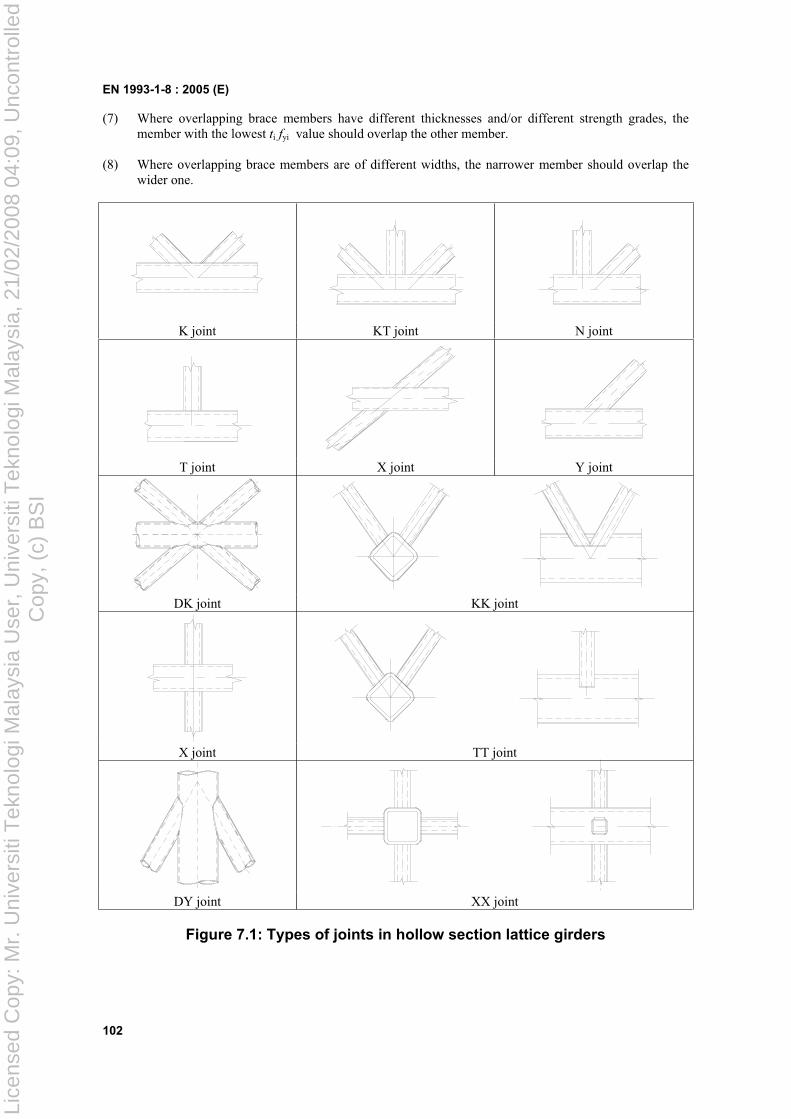
EN 1993-1-8 : 2005 (E)
102
(7) Where overlapping brace members have different thicknesses and/or different strength grades, the member with the lowest ti fyi value should overlap the other member.
(8) Where overlapping brace members are of different widths, the narrower member should overlap the wider one.
K joint KT joint N joint
T joint X joint Y joint
DK joint KK joint
X joint TT joint
DY joint XX joint
Figure 7.1: Types of joints in hollow section lattice girders
Lice
nsed
Cop
y: M
r. U
nive
rsiti
Tek
nolo
gi M
alay
sia
Use
r, U
nive
rsiti
Tek
nolo
gi M
alay
sia,
21/
02/2
008
04:0
9, U
ncon
trol
led
Cop
y, (
c) B
SI
EN 1993-1-8 : 2005 (E)
103
7.2 Design
7.2.1 General
(1)P The design values of the internal axial forces both in the brace members and in the chords at the ultimate limit state shall not exceed the design resistances of the members determined fromEN 1993-1-1.
(2)P The design values of the internal axial forces in the brace members at the ultimate limit state shallalso not exceed the design resistances of the joints given in 7.4, 7.5, 7.6 or 7.7 as appropriate.
(3) The stresses 0,Ed or p,Ed in the chord at a joint should be determined from:
0,Ed = 0,
,0
0
,0
el
EdEd
W
M
A
N ... (7.1)
p,Ed = 0,
,0
0
,
el
EdEdp
W
M
A
N ... (7.2)
where:
Np,Ed = 0
,,0 cosi
iEdiEd NN
7.2.2 Failure modes for hollow section joints
(1) The design joint resistances of connections between hollow sections and of connections between hollow sections and open sections, should be based on the following failure modes as applicable:
a) Chord face failure (plastic failure of the chord face) or chord plastification (plastic failure of the chord cross-section);
b) Chord side wall failure (or chord web failure) by yielding, crushing or instability (crippling or buckling of the chord side wall or chord web) under the compression brace member;
c) Chord shear failure;
d) Punching shear failure of a hollow section chord wall (crack initiation leading to rupture of the brace members from the chord member);
e) Brace failure with reduced effective width (cracking in the welds or in the brace members);
f) Local buckling failure of a brace member or of a hollow section chord member at the joint location.
NOTE: The phrases printed in boldface type in this list are used to describe the various failure modes in the tables of design resistances given in 7.4 to 7.7.
(2) Figure 7.2 illustrates failure modes (a) to (f) for joints between CHS brace and chord members.
(3) Figure 7.3 illustrates failure modes (a) to (f) for joints between RHS brace and chord members.
(4) Figure 7.4 illustrates failure modes (a) to (f) for joints between CHS or RHS brace members and I or H section chord members.
(5) Although the resistance of a joint with properly formed welds is generally higher under tension than under compression, the design resistance of the joint is generally based on the resistance of the brace in compression to avoid the possible excessive local deformation or reduced rotation capacity or deformation capacity which might otherwise occur.
Lice
nsed
Cop
y: M
r. U
nive
rsiti
Tek
nolo
gi M
alay
sia
Use
r, U
nive
rsiti
Tek
nolo
gi M
alay
sia,
21/
02/2
008
04:0
9, U
ncon
trol
led
Cop
y, (
c) B
SI
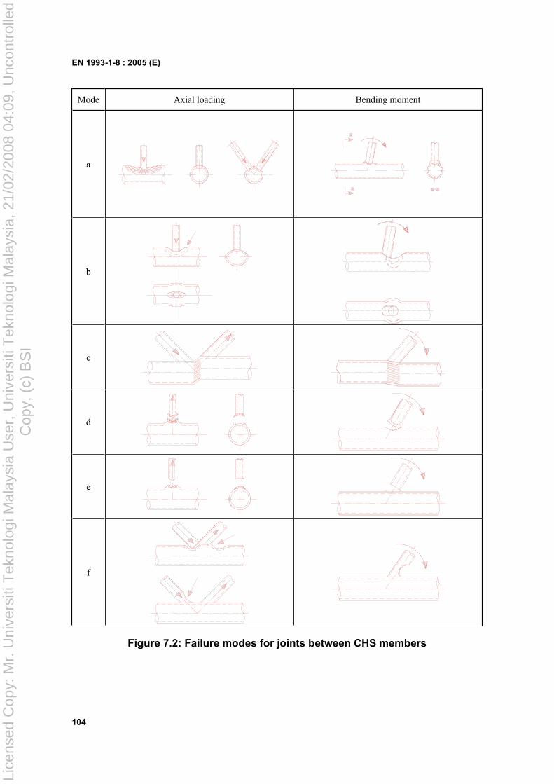
EN 1993-1-8 : 2005 (E)
104
Mode Axial loading Bending moment
a
b
c
d
e
f
Figure 7.2: Failure modes for joints between CHS members
Lice
nsed
Cop
y: M
r. U
nive
rsiti
Tek
nolo
gi M
alay
sia
Use
r, U
nive
rsiti
Tek
nolo
gi M
alay
sia,
21/
02/2
008
04:0
9, U
ncon
trol
led
Cop
y, (
c) B
SI
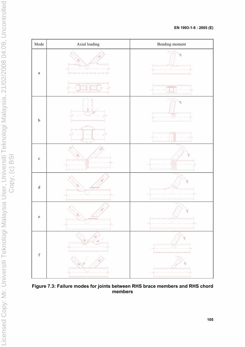
EN 1993-1-8 : 2005 (E)
105
Mode Axial loading Bending moment
a
b
c
d
e
f
Figure 7.3: Failure modes for joints between RHS brace members and RHS chord members
Lice
nsed
Cop
y: M
r. U
nive
rsiti
Tek
nolo
gi M
alay
sia
Use
r, U
nive
rsiti
Tek
nolo
gi M
alay
sia,
21/
02/2
008
04:0
9, U
ncon
trol
led
Cop
y, (
c) B
SI
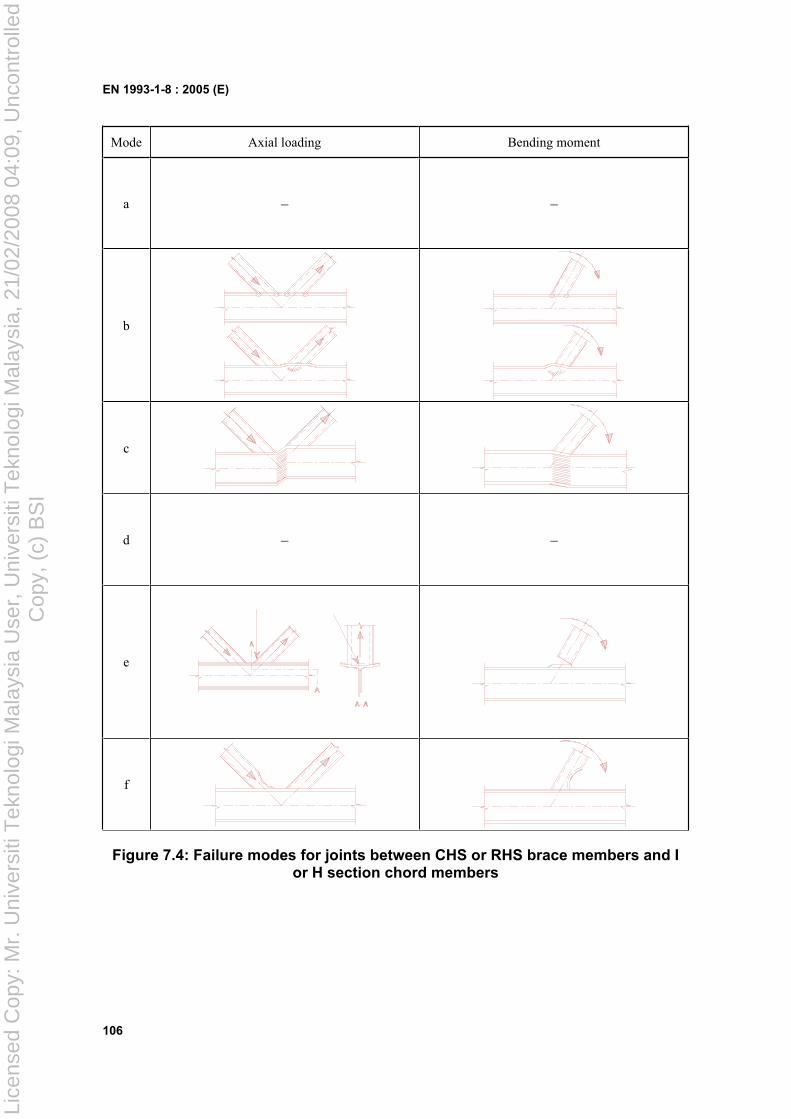
EN 1993-1-8 : 2005 (E)
106
Mode Axial loading Bending moment
a – –
b
c
d – –
e
f
Figure 7.4: Failure modes for joints between CHS or RHS brace members and I or H section chord members
Lice
nsed
Cop
y: M
r. U
nive
rsiti
Tek
nolo
gi M
alay
sia
Use
r, U
nive
rsiti
Tek
nolo
gi M
alay
sia,
21/
02/2
008
04:0
9, U
ncon
trol
led
Cop
y, (
c) B
SI
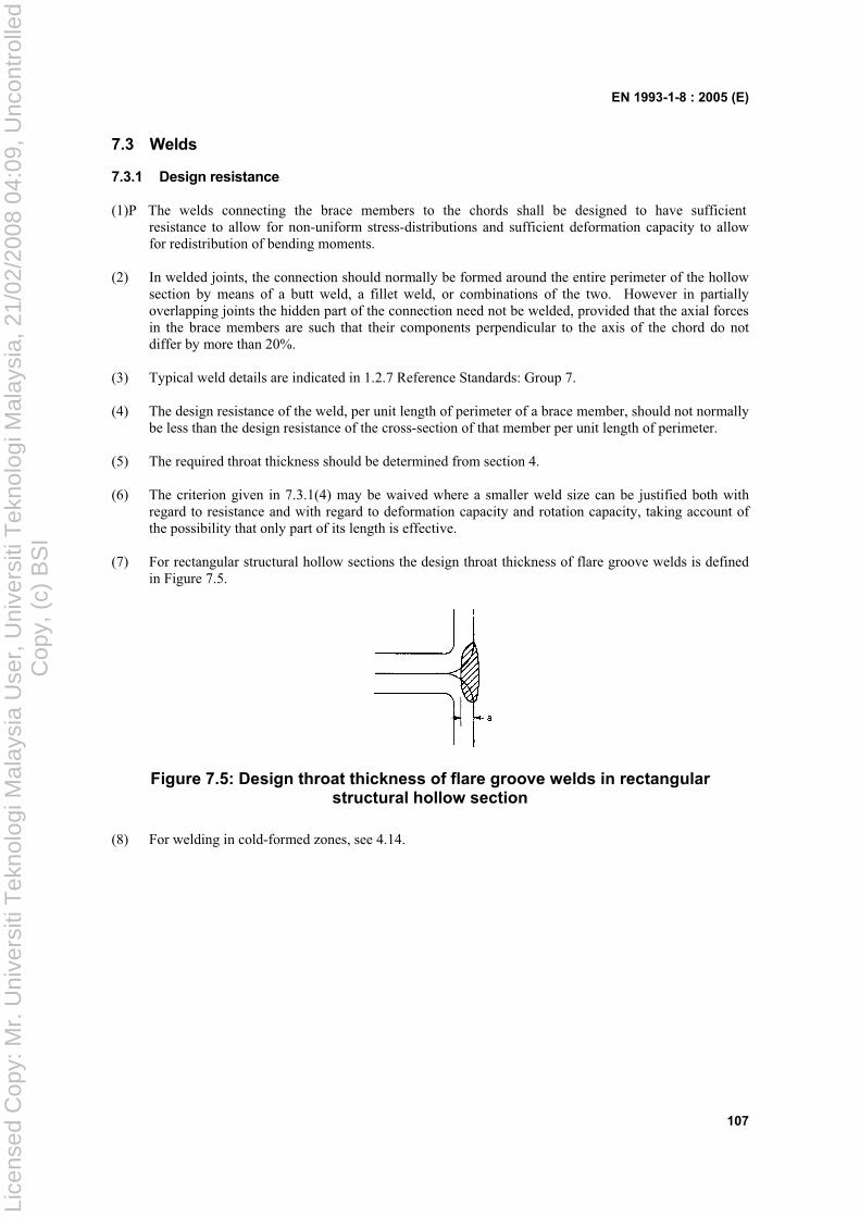
EN 1993-1-8 : 2005 (E)
107
7.3 Welds
7.3.1 Design resistance
(1)P The welds connecting the brace members to the chords shall be designed to have sufficientresistance to allow for non-uniform stress-distributions and sufficient deformation capacity to allow for redistribution of bending moments.
(2) In welded joints, the connection should normally be formed around the entire perimeter of the hollow section by means of a butt weld, a fillet weld, or combinations of the two. However in partially overlapping joints the hidden part of the connection need not be welded, provided that the axial forces in the brace members are such that their components perpendicular to the axis of the chord do not differ by more than 20%.
(3) Typical weld details are indicated in 1.2.7 Reference Standards: Group 7.
(4) The design resistance of the weld, per unit length of perimeter of a brace member, should not normally be less than the design resistance of the cross-section of that member per unit length of perimeter.
(5) The required throat thickness should be determined from section 4.
(6) The criterion given in 7.3.1(4) may be waived where a smaller weld size can be justified both with regard to resistance and with regard to deformation capacity and rotation capacity, taking account of the possibility that only part of its length is effective.
(7) For rectangular structural hollow sections the design throat thickness of flare groove welds is defined in Figure 7.5.
Figure 7.5: Design throat thickness of flare groove welds in rectangular structural hollow section
(8) For welding in cold-formed zones, see 4.14.
Lice
nsed
Cop
y: M
r. U
nive
rsiti
Tek
nolo
gi M
alay
sia
Use
r, U
nive
rsiti
Tek
nolo
gi M
alay
sia,
21/
02/2
008
04:0
9, U
ncon
trol
led
Cop
y, (
c) B
SI
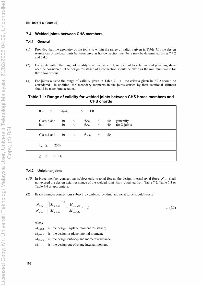
EN 1993-1-8 : 2005 (E)
108
7.4 Welded joints between CHS members
7.4.1 General
(1) Provided that the geometry of the joints is within the range of validity given in Table 7.1, the design resistances of welded joints between circular hollow section members may be determined using 7.4.2 and 7.4.3.
(2) For joints within the range of validity given in Table 7.1, only chord face failure and punching shear need be considered. The design resistance of a connection should be taken as the minimum value for these two criteria.
(3) For joints outside the range of validity given in Table 7.1, all the criteria given in 7.2.2 should be considered. In addition, the secondary moments in the joints caused by their rotational stiffness should be taken into account.
Table 7.1: Range of validity for welded joints between CHS brace members and CHS chords
0,2 di /d0 1,0
Class 2 and 10 d0/ t0 50 generally but 10 d0/ t0 40 for X joints
Class 2 and 10 di / ti 50
ov 25%
g t1 + t2
7.4.2 Uniplanar joints
(1)P In brace member connections subject only to axial forces, the design internal axial force Ni,Ed shallnot exceed the design axial resistance of the welded joint Ni,Rd obtained from Table 7.2, Table 7.3 or Table 7.4 as appropriate.
(2) Brace member connections subject to combined bending and axial force should satisfy:
Rdiop
Ediop
Rdiip
Ediip
Rdi
Edi
M
M
M
M
N
N
,,
,,
2
,,
,,
,
, 1,0 ... (7.3)
where:
Mip,i,Rd is the design in-plane moment resistance;
Mip,i,Ed is the design in-plane internal moment;
Mop,i,Rd is the design out-of-plane moment resistance;
Mop,i,Ed is the design out-of-plane internal moment.
Lice
nsed
Cop
y: M
r. U
nive
rsiti
Tek
nolo
gi M
alay
sia
Use
r, U
nive
rsiti
Tek
nolo
gi M
alay
sia,
21/
02/2
008
04:0
9, U
ncon
trol
led
Cop
y, (
c) B
SI
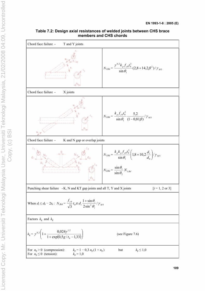
EN 1993-1-8 : 2005 (E)
109
Table 7.2: Design axial resistances of welded joints between CHS brace members and CHS chords
Chord face failure - T and Y joints
N1,Rd = 52
1
200
2,0
/)2,148,2(sin M
yp tfk
Chord face failure - X joints
N1,Rd = 51
200 /
)81,01(
2,5
sin M
yp tfk
Chord face failure - K and N gap or overlap joints
N1,Rd = 50
1
1
200 /2,108,1
sin M
ypg
d
dtfkk
N2,Rd = RdN ,12
1
sin
sin
Punching shear failure - K, N and KT gap joints and all T, Y and X joints [i = 1, 2 or 3]
When di d0 2t0 : Ni,Rd = 5200 /
sin2
sin1
3M
i
ii
ydt
f
Factors kg and kp
kg = 33,1/5,0exp1
024,01
0
2,12,0
tg (see Figure 7.6)
For np > 0 (compression): kp = 1 0,3 np (1 + np ) but kp 1,0 For np 0 (tension): kp = 1,0
Lice
nsed
Cop
y: M
r. U
nive
rsiti
Tek
nolo
gi M
alay
sia
Use
r, U
nive
rsiti
Tek
nolo
gi M
alay
sia,
21/
02/2
008
04:0
9, U
ncon
trol
led
Cop
y, (
c) B
SI
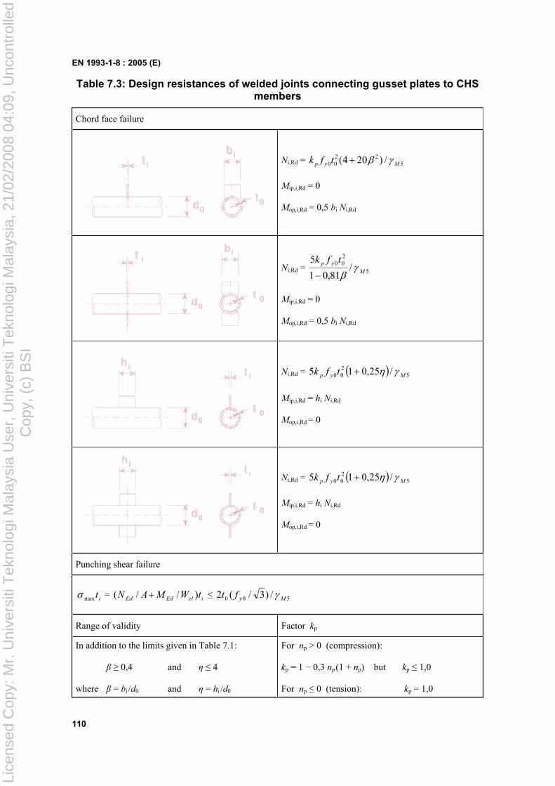
EN 1993-1-8 : 2005 (E)
110
Table 7.3: Design resistances of welded joints connecting gusset plates to CHS members
Chord face failure
Ni,Rd = 522
00 /)204( Myp tfk
Mip,i,Rd = 0
Mop,i,Rd = 0,5 bi Ni,Rd
Ni,Rd = 5
200 /
81,01
5M
yp tfk
Mip,i,Rd = 0
Mop,i,Rd = 0,5 bi Ni,Rd
Ni,Rd = 5200 /25,015 Myp tfk
Mip,i,Rd = hi Ni,Rd
Mop,i,Rd = 0
Ni,Rd = 5200 /25,015 Myp tfk
Mip,i,Rd = hi Ni,Rd
Mop,i,Rd = 0
Punching shear failure
itmax = ielEdEd tWMAN )//( 500 /)3/(2 Myft
Range of validity Factor kp
In addition to the limits given in Table 7.1:
0,4 and 4
where = bi /d0 and = hi /d0
For np > 0 (compression):
kp = 1 0,3 np(1 + np) but kp 1,0
For np 0 (tension): kp = 1,0
Lice
nsed
Cop
y: M
r. U
nive
rsiti
Tek
nolo
gi M
alay
sia
Use
r, U
nive
rsiti
Tek
nolo
gi M
alay
sia,
21/
02/2
008
04:0
9, U
ncon
trol
led
Cop
y, (
c) B
SI
EN 1993-1-8 : 2005 (E)
111
Table 7.4: Design resistances of welded joints connecting I, H or RHS sections to CHS members
Chord face failure
1h
d
1N
0
1b
t 0
N1,Rd = kp fy0 t02 (4 + 20 2)(1 + 0,25 ) / M5
Mip,1,Rd = h1 N1,Rd/(1 + 0,25 )
Mop,1,Rd = 0,5 b1 N1,Rd
1N
1N1h
d0t 0
N1,Rd = 5
200 /25,01
81,01
5M
yp tfk
Mip,1,Rd = h1 N1,Rd/(1 + 0,25 )
Mop,1,Rd = 0,5 b1 N1,Rd
1N
1h
d0
1b
t0
N1,Rd = kp fy0 t02 (4 + 20 2)(1 + 0,25 )/ M5
Mip,1,Rd = h1 N1,Rd
Mop,1,Rd = 0,5 b1 N1,Rd
1N
1N
1h
d0t 0
N1,Rd = 5
200 /25,01
81,01
5M
yp tfk
Mip,1,Rd = h1 N1,Rd
Mop,1,Rd = 0,5 b1 N1,Rd
Punching shear failure
I or H sections: 1maxt = 1elEdEd tW/MA/N 500 /)3/(2 Myft
RHS sections: 1maxt = 1elEdEd tW/MA/N 500 /)3/( Myft
Range of validity Factor kp
In addition to the limits given in Table 7.1:
0,4 and 4
where = b1 / d0 and = h1 / d0
For np > 0 (compression):
kp = 1 0,3 np (1 + np) but kp 1,0
For np 0 (tension): kp = 1,0
Lice
nsed
Cop
y: M
r. U
nive
rsiti
Tek
nolo
gi M
alay
sia
Use
r, U
nive
rsiti
Tek
nolo
gi M
alay
sia,
21/
02/2
008
04:0
9, U
ncon
trol
led
Cop
y, (
c) B
SI
EN 1993-1-8 : 2005 (E)
112
(3) The design internal moment Mi,Ed may be taken as the value at the point where the centreline of the brace member meets the face of the chord member.
(4) The design in-plane moment resistance and the design out-of-plane moment resistance Mi,Rd should be obtained from Table 7.3, Table 7.4 or Table 7.5 as appropriate.
(5) The special types of welded joints indicated in Table 7.6 should satisfy the appropriate design criteria specified for each type in that table.
(6) Values of the factor kg which is used in Table 7.2 for K, N and KT joints are given in Figure 7.6. The factor kg is used to cover both gap type and overlap type joints by adopting g for both the gap and the overlap and using negative values of g to represent the overlap q as defined in Figure 1.3(b).
1.0
1.5
2.0
2.5
3.0
3.5
4.0
4.5
-12 -8 -4 0 4 8 12
,
,
,
,
,
,
,
,
k
g / t0
g
= 7,5
= 10
= 12,5 = 15
= 17,5
= 20
= 22,5
= 25
Overlap type joints
(q = -g)
Gap type joints
Figure 7.6: Values of the factor kg for use in Table 7.2
Lice
nsed
Cop
y: M
r. U
nive
rsiti
Tek
nolo
gi M
alay
sia
Use
r, U
nive
rsiti
Tek
nolo
gi M
alay
sia,
21/
02/2
008
04:0
9, U
ncon
trol
led
Cop
y, (
c) B
SI
EN 1993-1-8 : 2005 (E)
113
Table 7.5: Design resistance moments of welded joints between CHS brace members and CHS chords
Chord face failure - T, X, and Y joints
d
M
1
1
d
t 0
0
ip,1
Mip,1,Rd = 51
1200 /
sin85,4 Mp
yk
dtf
Chord face failure - K, N, T, X and Y joints
d
1
1
d
t 0
0
Mop,1
Mop,1,Rd = 51
1200 /
81,01
7,2
sin Mp
yk
dtf
Punching shear failure - K and N gap joints and all T, X and Y joints
When d1 d0 2t0 :
Mip,1,Rd = 51
21
2100 /
sin4
sin31
3M
y dtf
Mop,1,Rd = 51
21
2100 /
sin4
sin3
3M
y dtf
Factor kp
For np > 0 (compression): kp = 1 0,3 np (1 + np ) but kp 1,0 For np 0 (tension): kp = 1,0
Lice
nsed
Cop
y: M
r. U
nive
rsiti
Tek
nolo
gi M
alay
sia
Use
r, U
nive
rsiti
Tek
nolo
gi M
alay
sia,
21/
02/2
008
04:0
9, U
ncon
trol
led
Cop
y, (
c) B
SI
EN 1993-1-8 : 2005 (E)
114
Table 7.6: Design criteria for special types of welded joints between CHS brace members and CHS chords
Type of joint Design criteria
The forces may be either tension or compression but should act in the same direction for both members.
N1,Ed N1,Rd
where N1,Rd is the value of N1,Rd for an X joint from Table 7.2.
Member 1 is always in compression and member 2 is always in tension.
N3N N1 2
31 2
N1,Ed sin 1 + N3,Ed sin 3 N1,Rd sin 1
N2,Ed sin 2 N1,Rd sin 1
where N1,Rd is the value of N1,Rd for a K joint from
Table 7.2 but with 0
1
d
d replaced by:
0
321
3d
ddd
All bracing members should always be in either compression or tension.
N1,Ed sin 1 + N2,Ed sin 2 Nx,Rd sin x
where Nx,Rd is the value of Nx,Rd for an X joint from Table 7.2, where Nx,Rd sin x is the larger of:
N1,Rd sin 1 and N2,Rd sin 2
Member 1 is always in compression and member 2 is always in tension. Ni,Ed Ni,Rd
where Ni,Rd is the value of Ni,Rd for a K joint from Table 7.2, provided that, in a gap-type joint, at section 1-1 the chord satisfies:
2
,0,
,0
2
,0,
,0
Rdpl
Ed
Rdpl
Ed
V
V
N
N 1,0
Lice
nsed
Cop
y: M
r. U
nive
rsiti
Tek
nolo
gi M
alay
sia
Use
r, U
nive
rsiti
Tek
nolo
gi M
alay
sia,
21/
02/2
008
04:0
9, U
ncon
trol
led
Cop
y, (
c) B
SI
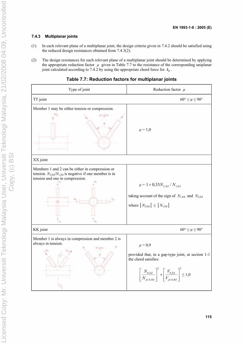
EN 1993-1-8 : 2005 (E)
115
7.4.3 Multiplanar joints
(1) In each relevant plane of a multiplanar joint, the design criteria given in 7.4.2 should be satisfied using the reduced design resistances obtained from 7.4.3(2).
(2) The design resistances for each relevant plane of a multiplanar joint should be determined by applying the appropriate reduction factor µ given in Table 7.7 to the resistance of the corresponding uniplanar joint calculated according to 7.4.2 by using the appropriate chord force for kp .
Table 7.7: Reduction factors for multiplanar joints
Type of joint Reduction factor µ
TT joint 60° 90°
Member 1 may be either tension or compression.
µ = 1,0
XX joint
Members 1 and 2 can be either in compression or tension. N2,Ed/N1,Ed is negative if one member is in tension and one in compression.
µ = EdEd NN ,1,2 /33,01
taking account of the sign of N1,Ed and N2,Ed
where N2,Ed N1,Ed
KK joint 60° 90°
Member 1 is always in compression and member 2 is always in tension. µ = 0,9
provided that, in a gap-type joint, at section 1-1 the chord satisfies:
2
,0,
,0
2
,0,
,0
Rdpl
Ed
Rdpl
Ed
V
V
N
N 1,0
Lice
nsed
Cop
y: M
r. U
nive
rsiti
Tek
nolo
gi M
alay
sia
Use
r, U
nive
rsiti
Tek
nolo
gi M
alay
sia,
21/
02/2
008
04:0
9, U
ncon
trol
led
Cop
y, (
c) B
SI
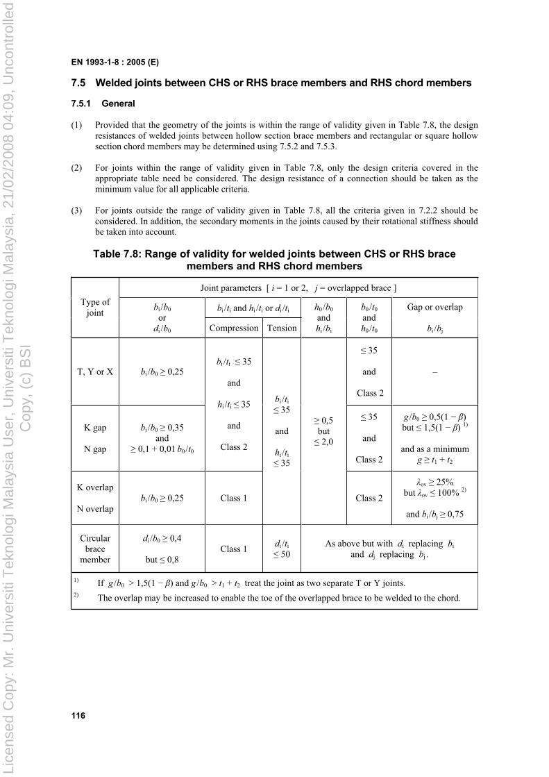
EN 1993-1-8 : 2005 (E)
116
7.5 Welded joints between CHS or RHS brace members and RHS chord members
7.5.1 General
(1) Provided that the geometry of the joints is within the range of validity given in Table 7.8, the design resistances of welded joints between hollow section brace members and rectangular or square hollow section chord members may be determined using 7.5.2 and 7.5.3.
(2) For joints within the range of validity given in Table 7.8, only the design criteria covered in the appropriate table need be considered. The design resistance of a connection should be taken as the minimum value for all applicable criteria.
(3) For joints outside the range of validity given in Table 7.8, all the criteria given in 7.2.2 should be considered. In addition, the secondary moments in the joints caused by their rotational stiffness should be taken into account.
Table 7.8: Range of validity for welded joints between CHS or RHS brace members and RHS chord members
Joint parameters [ i = 1 or 2, j = overlapped brace ]
bi /ti and hi /ti or di /tiType of
jointbi /b0
ordi /b0 Compression Tension
h0/b0
and hi /bi
b0 /t0
and h0 /t0
Gap or overlap
bi /bj
T, Y or X bi /b0 0,25
35
and
Class 2
–
K gap
N gap
bi /b0 0,35 and
0,1 + 0,01 b0/t0
bi /ti 35
and
hi /ti 35
and
Class 2
35
and
Class 2
g /b0 0,5(1 )but 1,5(1 ) 1)
and as a minimum g t1 + t2
K overlap
N overlapbi /b0 0,25 Class 1
bi /ti
35
and
hi /ti
35
0,5 but 2,0
Class 2
ov 25% but ov 100% 2)
and bi /bj 0,75
Circular brace
member
di /b0 0,4
but 0,8Class 1
di /ti
50As above but with di replacing bi
and dj replacing bj .
1) If g /b0 > 1,5(1 ) and g /b0 > t1 + t2 treat the joint as two separate T or Y joints. 2) The overlap may be increased to enable the toe of the overlapped brace to be welded to the chord.
Lice
nsed
Cop
y: M
r. U
nive
rsiti
Tek
nolo
gi M
alay
sia
Use
r, U
nive
rsiti
Tek
nolo
gi M
alay
sia,
21/
02/2
008
04:0
9, U
ncon
trol
led
Cop
y, (
c) B
SI
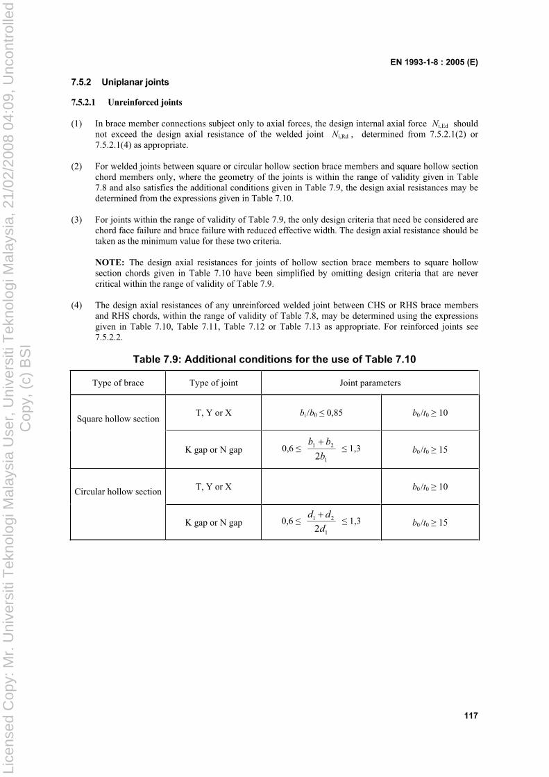
EN 1993-1-8 : 2005 (E)
117
7.5.2 Uniplanar joints
7.5.2.1 Unreinforced joints
(1) In brace member connections subject only to axial forces, the design internal axial force Ni,Ed should not exceed the design axial resistance of the welded joint Ni,Rd , determined from 7.5.2.1(2) or 7.5.2.1(4) as appropriate.
(2) For welded joints between square or circular hollow section brace members and square hollow section chord members only, where the geometry of the joints is within the range of validity given in Table 7.8 and also satisfies the additional conditions given in Table 7.9, the design axial resistances may be determined from the expressions given in Table 7.10.
(3) For joints within the range of validity of Table 7.9, the only design criteria that need be considered are chord face failure and brace failure with reduced effective width. The design axial resistance should be taken as the minimum value for these two criteria.
NOTE: The design axial resistances for joints of hollow section brace members to square hollow section chords given in Table 7.10 have been simplified by omitting design criteria that are never critical within the range of validity of Table 7.9.
(4) The design axial resistances of any unreinforced welded joint between CHS or RHS brace members and RHS chords, within the range of validity of Table 7.8, may be determined using the expressions given in Table 7.10, Table 7.11, Table 7.12 or Table 7.13 as appropriate. For reinforced joints see 7.5.2.2.
Table 7.9: Additional conditions for the use of Table 7.10
Type of brace Type of joint Joint parameters
T, Y or X bi /b0 0,85 b0 /t0 10Square hollow section
K gap or N gap 0,6 1
21
2b
bb 1,3 b0 /t0 15
T, Y or X b0 /t0 10Circular hollow section
K gap or N gap 0,61
21
2d
dd 1,3 b0 /t0 15
Lice
nsed
Cop
y: M
r. U
nive
rsiti
Tek
nolo
gi M
alay
sia
Use
r, U
nive
rsiti
Tek
nolo
gi M
alay
sia,
21/
02/2
008
04:0
9, U
ncon
trol
led
Cop
y, (
c) B
SI
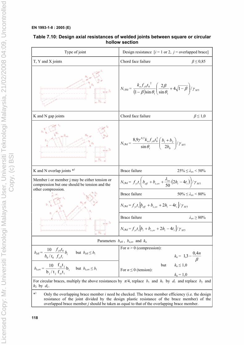
EN 1993-1-8 : 2005 (E)
118
Table 7.10: Design axial resistances of welded joints between square or circular hollow section
Type of joint Design resistance [i = 1 or 2, j = overlapped brace]
T, Y and X joints Chord face failure 0,85
N1,Rd = 511
200 /14
sin
2
sin1 M
yn tfk
K and N gap joints Chord face failure 1,0
Ni,Rd = 50
21
200
5,0
/2sin
9,8M
i
yn
b
bbtfk
K and N overlap joints *) Brace failure 25% ov < 50%
Ni,Rd = 5, /4250 Mii
ovoveeffiyi thbbtf
Brace failure 50% ov < 80%
Ni,Rd = 5, /42 Miioveeffiyi thbbtf
Brace failure ov 80%
Member i or member j may be either tension or compression but one should be tension and the other compression.
Ni,Rd = 5, /42 Miioveiiyi thbbtf
Parameters beff , be,ov and kn
beff = i
iyi
yb
tf
tf
tb
00
00 /
10 but beff bi
be,ov = iiyi
jyj
jj
btf
tf
t/b
10 but be,ov bi
For n > 0 (compression):
kn =n4,0
3,1
but kn 1,0 For n 0 (tension): kn = 1,0
For circular braces, multiply the above resistances by /4, replace b1 and h1 by d1 and replace b2 and h2 by d2 .
*) Only the overlapping brace member i need be checked. The brace member efficiency (i.e. the design resistance of the joint divided by the design plastic resistance of the brace member) of the overlapped brace member j should be taken as equal to that of the overlapping brace member.
Lice
nsed
Cop
y: M
r. U
nive
rsiti
Tek
nolo
gi M
alay
sia
Use
r, U
nive
rsiti
Tek
nolo
gi M
alay
sia,
21/
02/2
008
04:0
9, U
ncon
trol
led
Cop
y, (
c) B
SI
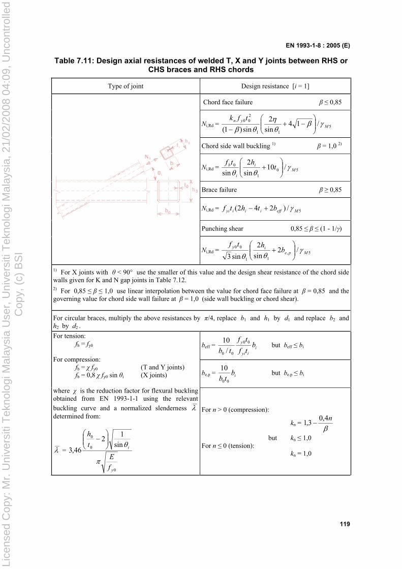
EN 1993-1-8 : 2005 (E)
119
Table 7.11: Design axial resistances of welded T, X and Y joints between RHS or CHS braces and RHS chords
Type of joint Design resistance [i = 1]
Chord face failure 0,85
Ni,Rd = 511
200 /14
sin
2
sin)1( M
yn tfk
Chord side wall buckling 1) = 1,0 2)
Ni,Rd = 501
0 /10sin
2
sin Mi
i
b thtf
Brace failure 0,85
Ni,Rd = 5/)242( Meffiiiyi bthtf
Punching shear 0,85 (1 - 1/ )
Ni,Rd = 5,11
00 /2sin
2
sin3Mpe
iyb
htf
1) For X joints with < 90° use the smaller of this value and the design shear resistance of the chord side walls given for K and N gap joints in Table 7.12. 2) For 0,85 1,0 use linear interpolation between the value for chord face failure at = 0,85 and the governing value for chord side wall failure at = 1,0 (side wall buckling or chord shear).
For circular braces, multiply the above resistances by /4, replace b1 and h1 by d1 and replace b2 and h2 by d2 .
beff = i
iyi
yb
tf
tf
tb
00
00 /
10 but beff bi
be,p = ibtb 00
10 but be.p bi
For tension: fb = fy0
For compression: fb = fy0 (T and Y joints) fb = 0,8 fy0 sin i (X joints)
where is the reduction factor for flexural buckling obtained from EN 1993-1-1 using the relevant
buckling curve and a normalized slenderness determined from:
=
0
0
0
sin
12
46,3
y
i
f
E
t
h
For n > 0 (compression):
kn = n4,0
3,1
but kn 1,0 For n 0 (tension): kn = 1,0
Lice
nsed
Cop
y: M
r. U
nive
rsiti
Tek
nolo
gi M
alay
sia
Use
r, U
nive
rsiti
Tek
nolo
gi M
alay
sia,
21/
02/2
008
04:0
9, U
ncon
trol
led
Cop
y, (
c) B
SI
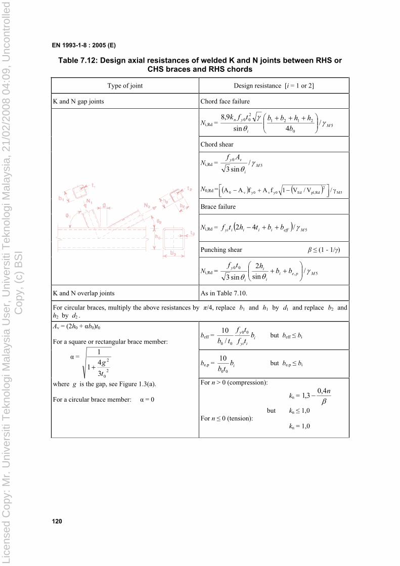
EN 1993-1-8 : 2005 (E)
120
Table 7.12: Design axial resistances of welded K and N joints between RHS or CHS braces and RHS chords
Type of joint Design resistance [i = 1 or 2]
K and N gap joints Chord face failure
Ni,Rd = 50
2121
200 /
4sin
9,8M
i
yn
b
hhbbtfk
Chord shear
Ni,Rd = 50 /sin3
M
i
vy Af
N0,Rd = 5M2
Rd,plEd0yv0yv0 /V/V1fAfAA
Brace failure
Ni,Rd = 5/42 Meffiiiiyi bbthtf
Punching shear (1 - 1/ )
Ni,Rd = 5,00 /
sin
2
sin3Mpei
i
i
i
ybb
htf
K and N overlap joints As in Table 7.10.
For circular braces, multiply the above resistances by /4, replace b1 and h1 by d1 and replace b2 and h2 by d2 .
beff = i
iyi
yb
tf
tf
tb
00
00 /
10 but beff bi
be,p = ibtb 00
10 but be.p bi
Av = (2h0 + b0)t0
For a square or rectangular brace member:
=
20
2
3
41
1
t
g
where g is the gap, see Figure 1.3(a).
For a circular brace member: = 0
For n > 0 (compression):
kn = n4,0
3,1
but kn 1,0 For n 0 (tension): kn = 1,0
Lice
nsed
Cop
y: M
r. U
nive
rsiti
Tek
nolo
gi M
alay
sia
Use
r, U
nive
rsiti
Tek
nolo
gi M
alay
sia,
21/
02/2
008
04:0
9, U
ncon
trol
led
Cop
y, (
c) B
SI
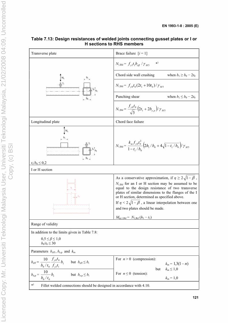
EN 1993-1-8 : 2005 (E)
121
Table 7.13: Design resistances of welded joints connecting gusset plates or I or H sections to RHS members
Transverse plate Brace failure [i = 1]
N1,Rd = 511 / Meffy btf *)
Chord side wall crushing when b1 b0 2t0
N1,Rd = 50100 /)102( My tttf
Punching shear when b1 b0 2t0
0
t i
bi
t
b0
h
1N
0
N1,Rd = 5,100 /22
3Mpe
ybt
tf
Longitudinal plate Chord face failure
0t0 h
b0
t i
ih
1N
t1/b0 0,2
N1,Rd = 5010101
200 //14/2
/1 M
ymbtbh
bt
tfk
I or H section
As a conservative approximation, if 2 1 ,
N1,Rd for an I or H section may be assumed to be equal to the design resistance of two transverse plates of similar dimensions to the flanges of the I or H section, determined as specified above.
If < 2 1 , a linear interpolation between one
and two plates should be made.
Mip,1,Rd = N1,Rd (h1 t1)
Range of validity
In addition to the limits given in Table 7.8:
0,5 1,0 b0/t0 30
Parameters beff , be,p and km
beff = 111
00
00 /
10b
tf
tf
tb y
y but beff bi
be,p = 100 /
10b
tb but be.p bi
For n > 0 (compression): km = )1(3,1 n
but km 1,0 For n 0 (tension): km = 1,0
*) Fillet welded connections should be designed in accordance with 4.10.
Lice
nsed
Cop
y: M
r. U
nive
rsiti
Tek
nolo
gi M
alay
sia
Use
r, U
nive
rsiti
Tek
nolo
gi M
alay
sia,
21/
02/2
008
04:0
9, U
ncon
trol
led
Cop
y, (
c) B
SI
EN 1993-1-8 : 2005 (E)
122
(5) Brace member connections subjected to combined bending and axial force should satisfy the following requirement:
Rdiop
Ediop
Rdiip
Ediip
Rdi
Edi
M
M
M
M
N
N
,,
,,
,,
,,
,
, 1,0 ... (7.4)
where:
Mip,i,Rd is the design in-plane moment resistance
Mip,i,Ed is the design in-plane internal moment
Mop,i,Rd is the design out-of-plane moment resistance
Mop,i,Ed is the design out-of-plane internal moment
(6) The design internal moment Mi,Ed may be taken as the value at the point where the centreline of the brace member meets the face of the chord member.
(7) For unreinforced joints, the design in-plane moment resistance and design out-of-plane moment resistance Mi,Rd should be obtained from Table 7.13 or Table 7.14 as appropriate. For reinforced joints see 7.5.2.2.
(8) The special types of welded joints indicated in Table 7.15 and Table 7.16 should satisfy the appropriate design criteria specified for each type in that table.
7.5.2.2 Reinforced joints
(1) Various types of joint reinforcement may be used. The appropriate type depends upon the failure mode that, in the absence of reinforcement, governs the design resistance of the joint.
(2) Flange reinforcing plates may be used to increase the resistance of the joint to chord face failure, punching shear failure or brace failure with reduced effective width.
(3) A pair of side plates may be used to reinforce a joint against chord side wall failure or chord shear failure.
(4) In order to avoid partial overlapping of brace members in a K or N joint, the brace members may be welded to a vertical stiffener.
(5) Any combinations of these types of joint reinforcement may also be used.
(6) The grade of steel used for the reinforcement should not be lower than that of the chord member.
(7) The design resistances of reinforced joints should be determined using Table 7.17 and Table 7.18.
Lice
nsed
Cop
y: M
r. U
nive
rsiti
Tek
nolo
gi M
alay
sia
Use
r, U
nive
rsiti
Tek
nolo
gi M
alay
sia,
21/
02/2
008
04:0
9, U
ncon
trol
led
Cop
y, (
c) B
SI
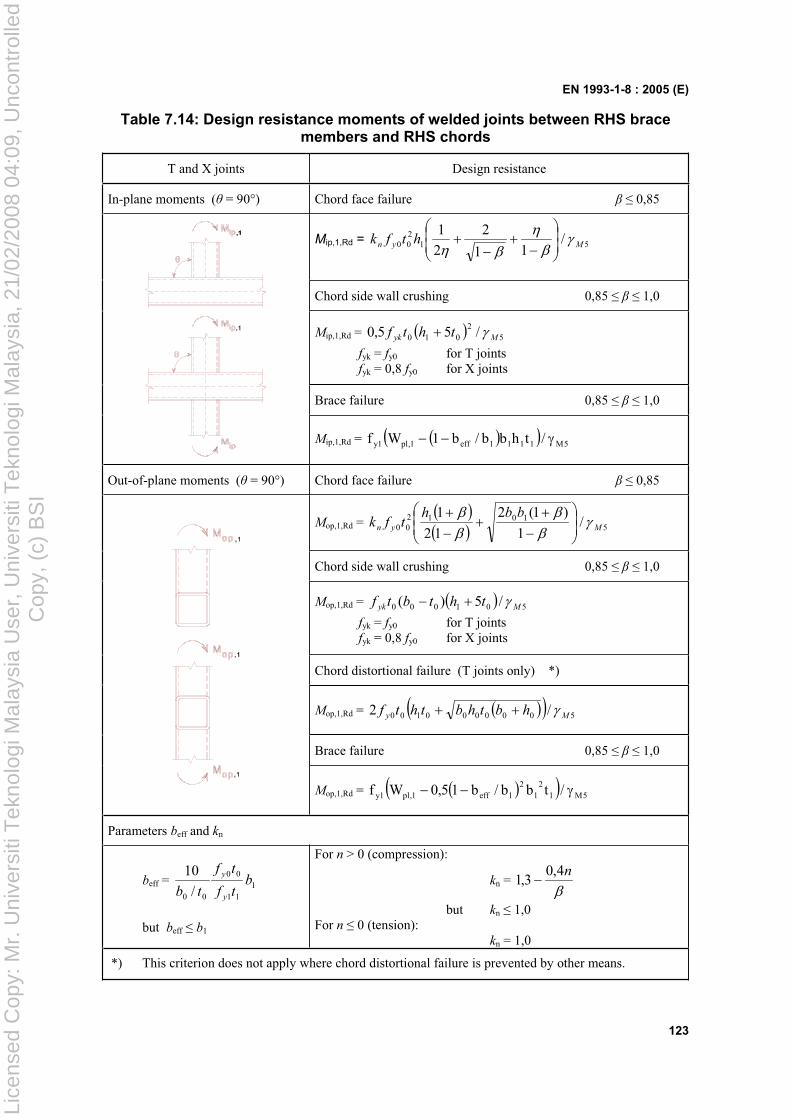
EN 1993-1-8 : 2005 (E)
123
Table 7.14: Design resistance moments of welded joints between RHS brace members and RHS chords
T and X joints Design resistance
In-plane moments ( = 90°) Chord face failure 0,85
Mip,1,Rd = 51200 /
11
2
2
1Myn htfk
Chord side wall crushing 0,85 1,0
Mip,1,Rd = 52
010 /55,0 Myk thtf
fyk = fy0 for T joints fyk = 0,8 fy0 for X joints
Brace failure 0,85 1,0
Mip,1,Rd = 5M1111eff1,pl1y /thbb/b1Wf
Out-of-plane moments ( = 90°) Chord face failure 0,85
Mop,1,Rd = 51012
00 /1
)1(2
12
1Myn
bbhtfk
Chord side wall crushing 0,85 1,0
Mop,1,Rd = 501000 /5)( Myk thtbtf
fyk = fy0 for T joints fyk = 0,8 fy0 for X joints
Chord distortional failure (T joints only) *)
Mop,1,Rd = 5000000100 /2 My hbthbthtf
Brace failure 0,85 1,0
Mop,1,Rd = 5M12
12
1eff1,pl1y /tbb/b15,0Wf
Parameters beff and kn
beff = 111
00
00 /
10b
tf
tf
tb y
y
but beff b1
For n > 0 (compression):
kn = n4,0
3,1
but kn 1,0 For n 0 (tension): kn = 1,0
*) This criterion does not apply where chord distortional failure is prevented by other means.
Lice
nsed
Cop
y: M
r. U
nive
rsiti
Tek
nolo
gi M
alay
sia
Use
r, U
nive
rsiti
Tek
nolo
gi M
alay
sia,
21/
02/2
008
04:0
9, U
ncon
trol
led
Cop
y, (
c) B
SI
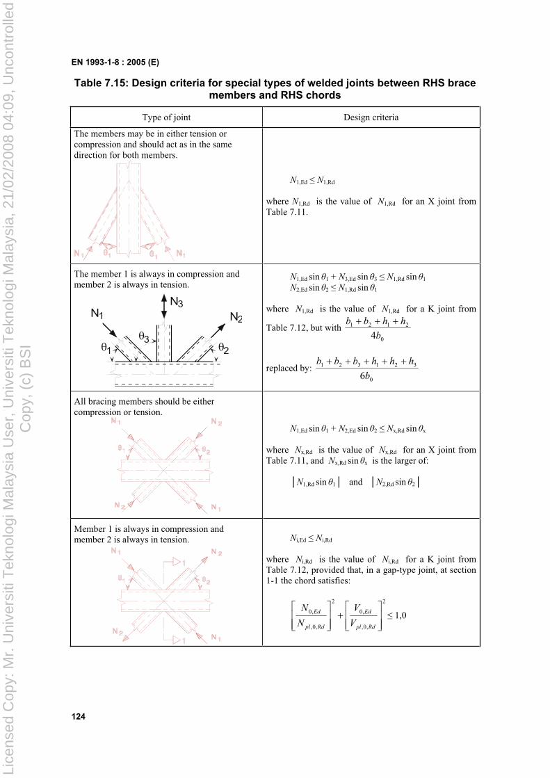
EN 1993-1-8 : 2005 (E)
124
Table 7.15: Design criteria for special types of welded joints between RHS brace members and RHS chords
Type of joint Design criteria
The members may be in either tension or compression and should act as in the same direction for both members.
N1,Ed N1,Rd
where N1,Rd is the value of N1,Rd for an X joint from Table 7.11.
The member 1 is always in compression and member 2 is always in tension.
N3N N1 2
31 2
N1,Ed sin 1 + N3,Ed sin 3 N1,Rd sin 1
N2,Ed sin 2 N1,Rd sin 1
where N1,Rd is the value of N1,Rd for a K joint from
Table 7.12, but with 0
2121
4b
hhbb
replaced by: 0
321321
6b
hhhbbb
All bracing members should be either compression or tension.
N1,Ed sin 1 + N2,Ed sin 2 Nx,Rd sin x
where Nx,Rd is the value of Nx,Rd for an X joint from Table 7.11, and Nx,Rd sin x is the larger of:
N1,Rd sin 1 and N2,Rd sin 2
Member 1 is always in compression and member 2 is always in tension. Ni,Ed Ni,Rd
where Ni,Rd is the value of Ni,Rd for a K joint from Table 7.12, provided that, in a gap-type joint, at section 1-1 the chord satisfies:
2
,0,
,0
2
,0,
,0
Rdpl
Ed
Rdpl
Ed
V
V
N
N 1,0
Lice
nsed
Cop
y: M
r. U
nive
rsiti
Tek
nolo
gi M
alay
sia
Use
r, U
nive
rsiti
Tek
nolo
gi M
alay
sia,
21/
02/2
008
04:0
9, U
ncon
trol
led
Cop
y, (
c) B
SI
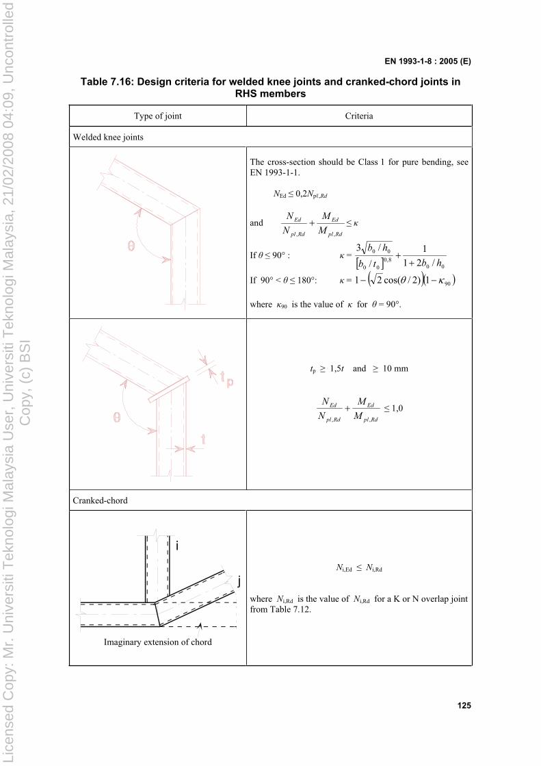
EN 1993-1-8 : 2005 (E)
125
Table 7.16: Design criteria for welded knee joints and cranked-chord joints in RHS members
Type of joint Criteria
Welded knee joints
The cross-section should be Class 1 for pure bending, see EN 1993-1-1.
NEd 0,2Np ,Rd
and Rdpl
Ed
Rdpl
Ed
M
M
N
N
,,
If 90° : = 00
8,000
00
/21
1
/
/3
hbtb
hb
If 90° < 180°: = 901)2/cos(21
where 90 is the value of for = 90°.
tp 1,5t and 10 mm
Rdpl
Ed
Rdpl
Ed
M
M
N
N
,,
1,0
Cranked-chord
i
j
Imaginary extension of chord
Ni,Ed Ni,Rd
where Ni,Rd is the value of Ni,Rd for a K or N overlap joint from Table 7.12.
Lice
nsed
Cop
y: M
r. U
nive
rsiti
Tek
nolo
gi M
alay
sia
Use
r, U
nive
rsiti
Tek
nolo
gi M
alay
sia,
21/
02/2
008
04:0
9, U
ncon
trol
led
Cop
y, (
c) B
SI
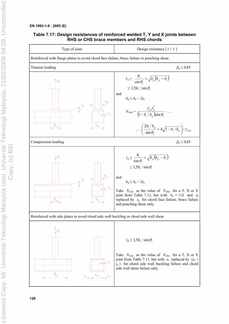
EN 1993-1-8 : 2005 (E)
126
Table 7.17: Design resistances of reinforced welded T, Y and X joints between RHS or CHS brace members and RHS chords
Type of joint Design resistance [ i = 1 ]
Reinforced with flange plates to avoid chord face failure, brace failure or punching shear.
Tension loading p 0,85
p ipp
i
i bbbh
sin
iih sin/5,1and
bp b0 2t0
Ni,Rd =ipi
pyp
bb
tf
sin/1
2
…
... 5//14sin
/2Mpi
i
pibb
bh
Compression loading p 0,85
p ipp
i
i bbbh
sin
iih sin/5,1
and bp b0 2t0
Take Ni,Rd as the value of Ni,Rd for a T, X or Y joint from Table 7.11, but with kn = 1,0 and t0
replaced by tp for chord face failure, brace failure and punching shear only.
Reinforced with side plates to avoid chord side wall buckling or chord side wall shear.
p iih sin/5,1
Take Ni,Rd as the value of Ni,Rd for a T, X or Y joint from Table 7.11, but with t0 replaced by (t0 + tp ) for chord side wall buckling failure and chord side wall shear failure only.
Lice
nsed
Cop
y: M
r. U
nive
rsiti
Tek
nolo
gi M
alay
sia
Use
r, U
nive
rsiti
Tek
nolo
gi M
alay
sia,
21/
02/2
008
04:0
9, U
ncon
trol
led
Cop
y, (
c) B
SI
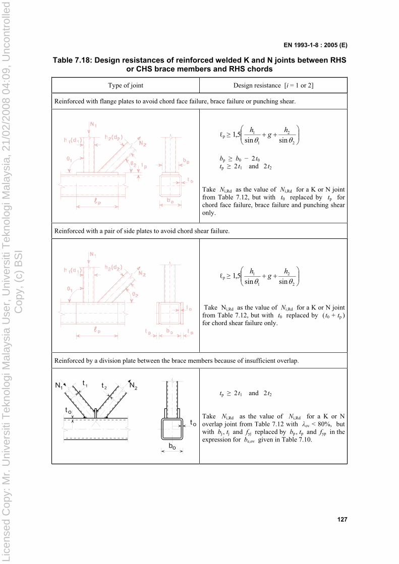
EN 1993-1-8 : 2005 (E)
127
Table 7.18: Design resistances of reinforced welded K and N joints between RHS or CHS brace members and RHS chords
Type of joint Design resistance [i = 1 or 2]
Reinforced with flange plates to avoid chord face failure, brace failure or punching shear.
p
2
2
1
1
sinsin5,1
hg
h
bp b0 2 t0
tp 2 t1 and 2 t2
Take Ni,Rd as the value of Ni,Rd for a K or N joint from Table 7.12, but with t0 replaced by tp for chord face failure, brace failure and punching shear only.
Reinforced with a pair of side plates to avoid chord shear failure.
p
2
2
1
1
sinsin5,1
hg
h
Take Ni,Rd as the value of Ni,Rd for a K or N joint from Table 7.12, but with t0 replaced by ( t0 + tp )for chord shear failure only.
Reinforced by a division plate between the brace members because of insufficient overlap.
t o
bo
to
t t1 2 N2N1 tp 2 t1 and 2 t2
Take Ni,Rd as the value of Ni,Rd for a K or N overlap joint from Table 7.12 with ov < 80%, but with bj , tj and fyj replaced by bp , tp and fyp in the expression for be,ov given in Table 7.10.
Lice
nsed
Cop
y: M
r. U
nive
rsiti
Tek
nolo
gi M
alay
sia
Use
r, U
nive
rsiti
Tek
nolo
gi M
alay
sia,
21/
02/2
008
04:0
9, U
ncon
trol
led
Cop
y, (
c) B
SI
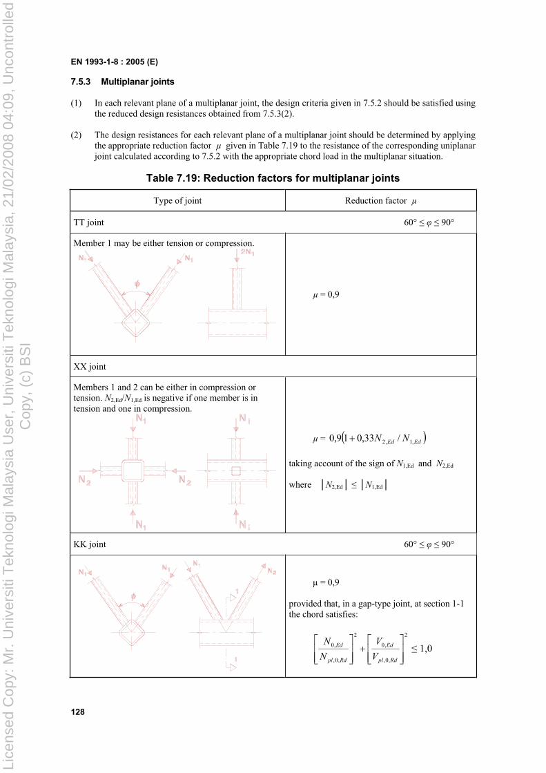
EN 1993-1-8 : 2005 (E)
128
7.5.3 Multiplanar joints
(1) In each relevant plane of a multiplanar joint, the design criteria given in 7.5.2 should be satisfied using the reduced design resistances obtained from 7.5.3(2).
(2) The design resistances for each relevant plane of a multiplanar joint should be determined by applying the appropriate reduction factor µ given in Table 7.19 to the resistance of the corresponding uniplanar joint calculated according to 7.5.2 with the appropriate chord load in the multiplanar situation.
Table 7.19: Reduction factors for multiplanar joints
Type of joint Reduction factor µ
TT joint 60° 90°
Member 1 may be either tension or compression.
µ = 0,9
XX joint
Members 1 and 2 can be either in compression or tension. N2,Ed/N1,Ed is negative if one member is in tension and one in compression.
µ = EdEd NN ,1,2 /33,019,0
taking account of the sign of N1,Ed and N2,Ed
where N2,Ed N1,Ed
KK joint 60° 90°
µ = 0,9
provided that, in a gap-type joint, at section 1-1 the chord satisfies:
2
,0,
,0
2
,0,
,0
Rdpl
Ed
Rdpl
Ed
V
V
N
N 1,0
Lice
nsed
Cop
y: M
r. U
nive
rsiti
Tek
nolo
gi M
alay
sia
Use
r, U
nive
rsiti
Tek
nolo
gi M
alay
sia,
21/
02/2
008
04:0
9, U
ncon
trol
led
Cop
y, (
c) B
SI
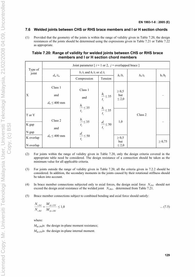
EN 1993-1-8 : 2005 (E)
129
7.6 Welded joints between CHS or RHS brace members and I or H section chords
(1) Provided that the geometry of the joints is within the range of validity given in Table 7.20, the design resistances of the joints should be determined using the expressions given in Table 7.21 or Table 7.22 as appropriate.
Table 7.20: Range of validity for welded joints between CHS or RHS brace members and I or H section chord members
Joint parameter [ i = 1 or 2, j = overlapped brace ]
bi /ti and hi /ti or di /ti
Type of joint
dw/twCompression Tension
hi /bi b0/tf bi /bj
X
Class 1
and
dw 400 mm
0,5 but 2,0
–
T or Y
K gap
N gap
1,0 –
K overlap
N overlap
Class 2
and
dw 400 mm
Class 1
and
i
i
t
h 35
i
i
t
b 35
i
i
t
d 50
i
i
t
h 35
i
i
t
b 35
i
i
t
d 50
0,5 but 2,0
Class 2
0,75
(2) For joints within the range of validity given in Table 7.20, only the design criteria covered in the appropriate table need be considered. The design resistance of a connection should be taken as the minimum value for all applicable criteria.
(3) For joints outside the range of validity given in Table 7.20, all the criteria given in 7.2.2 should be considered. In addition, the secondary moments in the joints caused by their rotational stiffness should be taken into account.
(4) In brace member connections subjected only to axial forces, the design axial force Ni,Ed should not exceed the design axial resistance of the welded joint Ni,Rd , determined from Table 7.21.
(5) Brace member connections subject to combined bending and axial force should satisfy:
Rdiip
Ediip
Rdi
Edi
M
M
N
N
,,
,,
,
, 1,0 ... (7.5)
where:
Mip,i,Rd is the design in-plane moment resistance;
Mip,i,Ed is the design in-plane internal moment.
Lice
nsed
Cop
y: M
r. U
nive
rsiti
Tek
nolo
gi M
alay
sia
Use
r, U
nive
rsiti
Tek
nolo
gi M
alay
sia,
21/
02/2
008
04:0
9, U
ncon
trol
led
Cop
y, (
c) B
SI
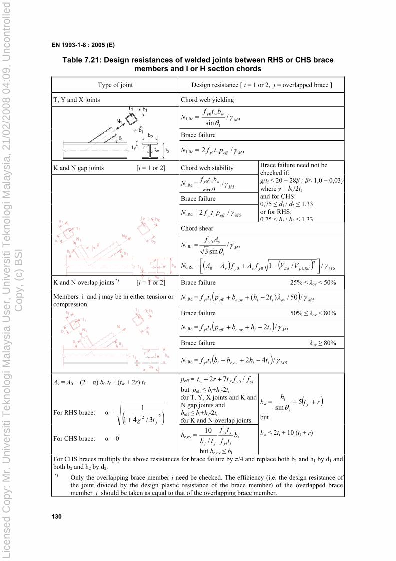
EN 1993-1-8 : 2005 (E)
130
Table 7.21: Design resistances of welded joints between RHS or CHS brace members and I or H section chords
Type of joint Design resistance [ i = 1 or 2, j = overlapped brace ]
T, Y and X joints Chord web yielding
N1,Rd = 51
0 /sin M
wwy btf
Brace failure 1
bo
tw oht f
N1
b1
h11t
rN1,Rd = 511 /2 Meffy ptf
K and N gap joints [i = 1 or 2] Chord web stability
Ni,Rd = 5
1
0 /sin M
wwy btf
Brace failure
Ni,Rd = 5/2 Meffiyi ptf
Brace failure need not be checked if: g/tf 20 28 ; 1,0 0,03where = b0/2tf
and for CHS: 0,75 d1 / d2 1,33 or for RHS: 0,75 b1 / b2 1,33
Chord shear
Ni,Rd = 50 /sin3
M
i
vy Af
N0,Rd = 52
,1000 //1 MRdpEdyvyv VVfAfAA
K and N overlap joints *) [i = 1 or 2] Brace failure 25% ov < 50%
Ni,Rd = 5, /50/)2( Moviioveeffiyi thbptf
Brace failure 50% ov < 80%
Ni,Rd = 5, /2 Miioveeffiyi thbptf
Brace failure ov 80%
Members i and j may be in either tension or compression.
Ni,Rd = 5, /42 Miioveiiyi thbbtf
peff = yiyfw fftrt /72 0
but peff bi+hi-2ti
for T, Y, X joints and K and N gap joints and beff bi+hi-2ti
for K and N overlap joints.
Av = A0 (2 ) b0 tf + (tw + 2r) tf
For RHS brace: = 22 3/41
1
ftg
For CHS brace: = 0 be,ov = i
iyi
jyj
jj
btf
tf
tb /
10
but be,ov bi
bw = rth
f
i
i 5sin
but
bw 2ti + 10 (tf + r)
For CHS braces multiply the above resistances for brace failure by /4 and replace both b1 and h1 by d1 andboth b2 and h2 by d2. *) Only the overlapping brace member i need be checked. The efficiency (i.e. the design resistance of
the joint divided by the design plastic resistance of the brace member) of the overlapped brace member j should be taken as equal to that of the overlapping brace member.
Lice
nsed
Cop
y: M
r. U
nive
rsiti
Tek
nolo
gi M
alay
sia
Use
r, U
nive
rsiti
Tek
nolo
gi M
alay
sia,
21/
02/2
008
04:0
9, U
ncon
trol
led
Cop
y, (
c) B
SI
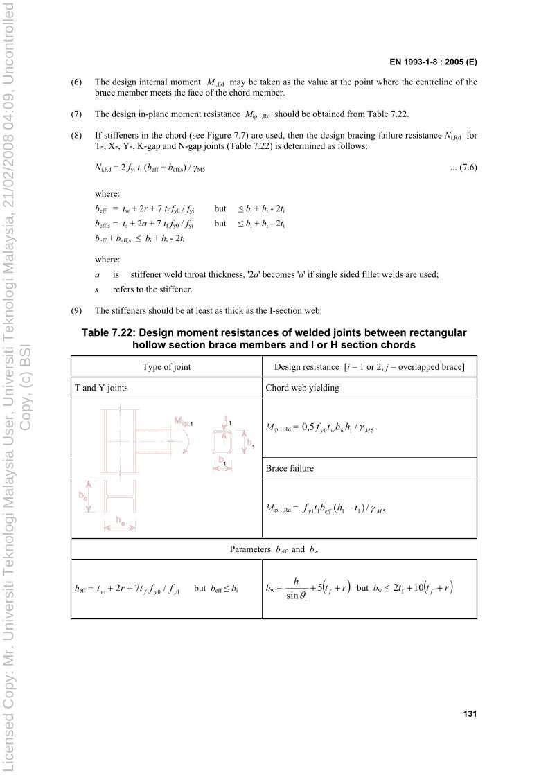
EN 1993-1-8 : 2005 (E)
131
(6) The design internal moment Mi,Ed may be taken as the value at the point where the centreline of the brace member meets the face of the chord member.
(7) The design in-plane moment resistance Mip,1,Rd should be obtained from Table 7.22.
(8) If stiffeners in the chord (see Figure 7.7) are used, then the design bracing failure resistance Ni,Rd for T-, X-, Y-, K-gap and N-gap joints (Table 7.22) is determined as follows:
Ni,Rd = 2 fyi ti (beff + beff,s) / M5 ... (7.6)
where:
beff = tw + 2r + 7 tf fy0 / fyi but bi + hi - 2ti
beff,s = ts + 2a + 7 tf fy0 / fyi but bi + hi - 2ti
beff + beff,s bi + hi - 2ti
where:
a is stiffener weld throat thickness, '2a' becomes 'a' if single sided fillet welds are used;
s refers to the stiffener.
(9) The stiffeners should be at least as thick as the I-section web.
Table 7.22: Design moment resistances of welded joints between rectangular hollow section brace members and I or H section chords
Type of joint Design resistance [i = 1 or 2, j = overlapped brace]
T and Y joints Chord web yielding
Mip,1,Rd = 510 /5,0 Mwwy hbtf
Brace failure
Mip,1,Rd = 51111 /)( Meffy thbtf
Parameters beff and bw
beff = 10 /72 yyfw fftrt but beff bi bw = rth
f5sin 1
1 but bw rtt f102 1
Lice
nsed
Cop
y: M
r. U
nive
rsiti
Tek
nolo
gi M
alay
sia
Use
r, U
nive
rsiti
Tek
nolo
gi M
alay
sia,
21/
02/2
008
04:0
9, U
ncon
trol
led
Cop
y, (
c) B
SI
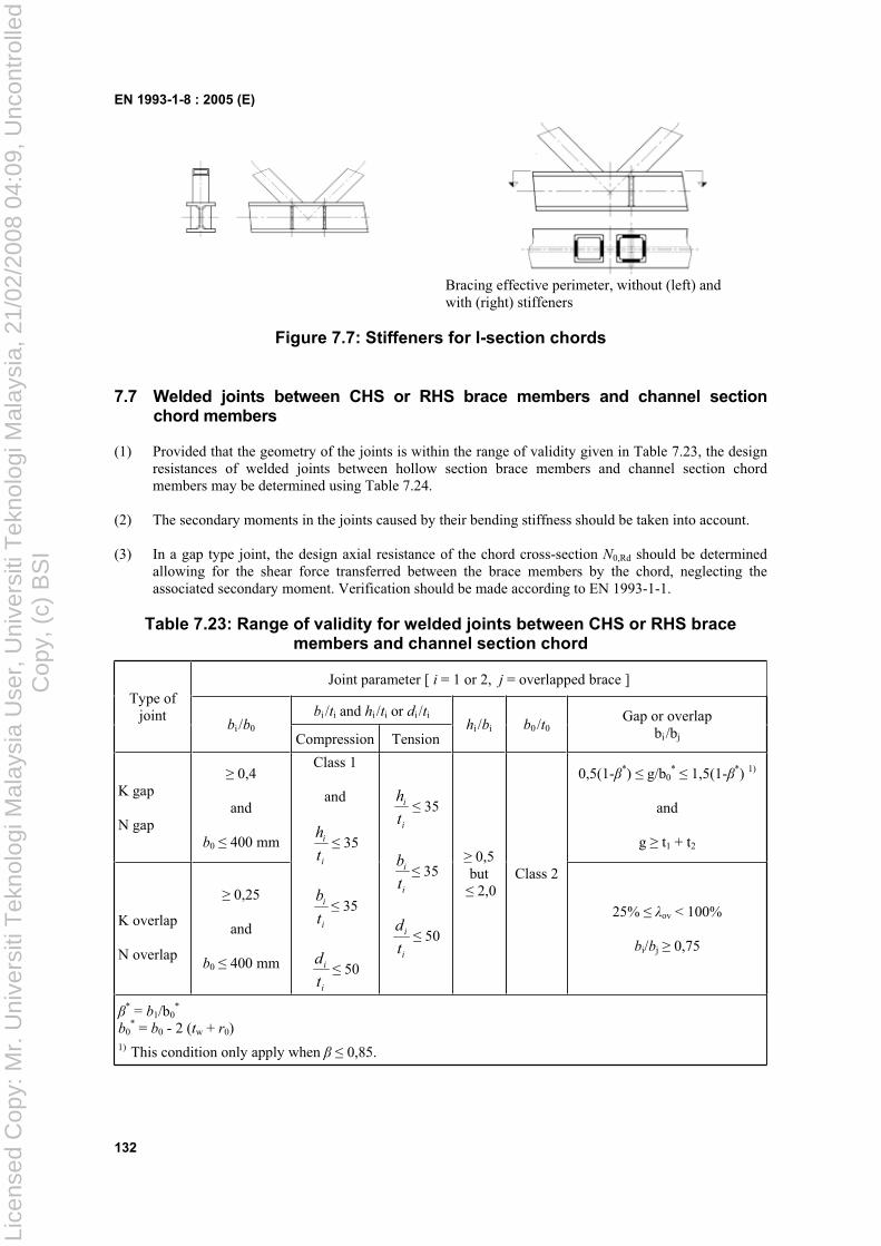
EN 1993-1-8 : 2005 (E)
132
Bracing effective perimeter, without (left) and with (right) stiffeners
Figure 7.7: Stiffeners for I-section chords
7.7 Welded joints between CHS or RHS brace members and channel section chord members
(1) Provided that the geometry of the joints is within the range of validity given in Table 7.23, the design resistances of welded joints between hollow section brace members and channel section chord members may be determined using Table 7.24.
(2) The secondary moments in the joints caused by their bending stiffness should be taken into account.
(3) In a gap type joint, the design axial resistance of the chord cross-section N0,Rd should be determined allowing for the shear force transferred between the brace members by the chord, neglecting the associated secondary moment. Verification should be made according to EN 1993-1-1.
Table 7.23: Range of validity for welded joints between CHS or RHS brace members and channel section chord
Joint parameter [ i = 1 or 2, j = overlapped brace ]
bi /ti and hi /ti or di /ti
Type of joint
bi /b0Compression Tension
hi /bi b0 /t0Gap or overlap
bi /bj
K gap
N gap
0,4
and
b0 400 mm
0,5(1- *) g/b0* 1,5(1- *) 1)
and
g t1 + t2
K overlap
N overlap
0,25
and
b0 400 mm
Class 1
and
i
i
t
h 35
i
i
t
b 35
i
i
t
d 50
i
i
t
h 35
i
i
t
b 35
i
i
t
d 50
0,5 but 2,0
Class 2
25% ov < 100%
bi/bj 0,75
* = b1/b0*
b0* = b0 - 2 (tw + r0)
1) This condition only apply when 0,85.
Lice
nsed
Cop
y: M
r. U
nive
rsiti
Tek
nolo
gi M
alay
sia
Use
r, U
nive
rsiti
Tek
nolo
gi M
alay
sia,
21/
02/2
008
04:0
9, U
ncon
trol
led
Cop
y, (
c) B
SI
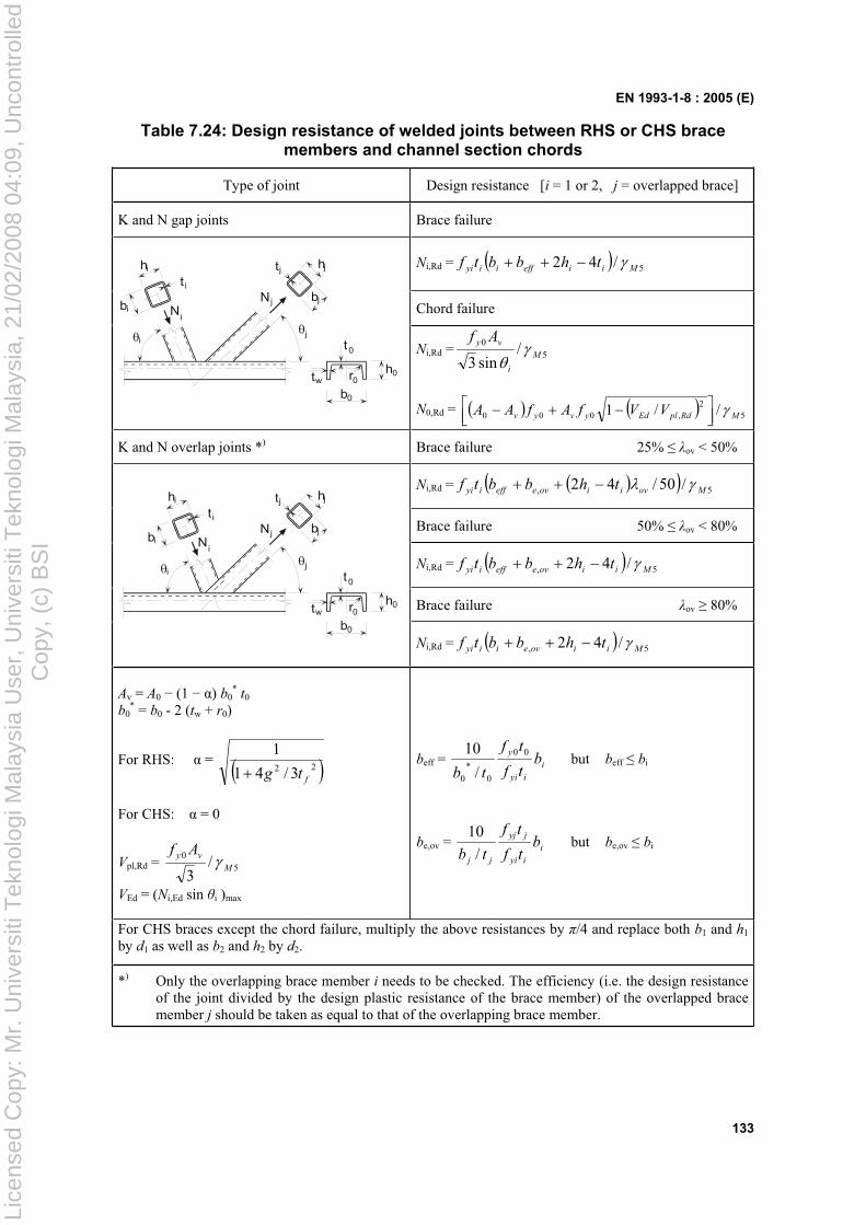
EN 1993-1-8 : 2005 (E)
133
Table 7.24: Design resistance of welded joints between RHS or CHS brace members and channel section chords
Type of joint Design resistance [i = 1 or 2, j = overlapped brace]
K and N gap joints Brace failure
Ni,Rd = 5/42 Miieffiiyi thbbtf
Chord failure
t
t
r
b
hw
0
0
0
0
N bjj
htj j
j
t
b N
h
i
i
i
i
iNi,Rd = 5
0 /sin3
M
i
vy Af
N0,Rd = 52
,000 //1 MRdplEdyvyv VVfAfAA
K and N overlap joints *) Brace failure 25% ov < 50%
Ni,Rd = 5, /50/42 Moviioveeffiyi thbbtf
Brace failure 50% ov < 80%
Ni,Rd = 5, /42 Miioveeffiyi thbbtf
Brace failure ov 80% t
t
b
hw
0
0
0
N bjj
htj j
j
t
b N
h
i
i
i
i
i
r0
Ni,Rd = 5, /42 Miioveiiyi thbbtf
Av = A0 (1 ) b0* t0
b0* = b0 - 2 (tw + r0)
For RHS: = 22 3/41
1
ftg
For CHS: = 0
Vpl,Rd = 50 /3
M
vy Af
VEd = (Ni,Ed sin i )max
beff = i
iyi
yb
tf
tf
tb
00
0*
0 /
10 but beff bi
be,ov = i
iyi
jyj
jj
btf
tf
tb /
10 but be,ov bi
For CHS braces except the chord failure, multiply the above resistances by /4 and replace both b1 and h1
by d1 as well as b2 and h2 by d2.
*) Only the overlapping brace member i needs to be checked. The efficiency (i.e. the design resistance of the joint divided by the design plastic resistance of the brace member) of the overlapped brace member j should be taken as equal to that of the overlapping brace member.
Lice
nsed
Cop
y: M
r. U
nive
rsiti
Tek
nolo
gi M
alay
sia
Use
r, U
nive
rsiti
Tek
nolo
gi M
alay
sia,
21/
02/2
008
04:0
9, U
ncon
trol
led
Cop
y, (
c) B
SI
BS EN 1993-1-8:2005
BSI
389 Chiswick High Road
London
W4 4AL
BSI — British Standards Institution
BSI is the independent national body responsible for preparing British Standards. It presents the UK view on standards in Europe and at the international level. It is incorporated by Royal Charter.
Revisions
British Standards are updated by amendment or revision. Users of British Standards should make sure that they possess the latest amendments or editions.
It is the constant aim of BSI to improve the quality of our products and services. We would be grateful if anyone finding an inaccuracy or ambiguity while using this British Standard would inform the Secretary of the technical committee responsible, the identity of which can be found on the inside front cover. Tel: +44 (0)20 8996 9000. Fax: +44 (0)20 8996 7400.
BSI offers members an individual updating service called PLUS which ensures that subscribers automatically receive the latest editions of standards.
Buying standards
Orders for all BSI, international and foreign standards publications should be addressed to Customer Services. Tel: +44 (0)20 8996 9001. Fax: +44 (0)20 8996 7001. Email: [email protected]. Standards are also available from the BSI website at http://www.bsi-global.com.
In response to orders for international standards, it is BSI policy to supply the BSI implementation of those that have been published as British Standards, unless otherwise requested.
Information on standards
BSI provides a wide range of information on national, European and international standards through its Library and its Technical Help to Exporters Service. Various BSI electronic information services are also available which give details on all its products and services. Contact the Information Centre. Tel: +44 (0)20 8996 7111. Fax: +44 (0)20 8996 7048. Email: [email protected].
Subscribing members of BSI are kept up to date with standards developments and receive substantial discounts on the purchase price of standards. For details of these and other benefits contact Membership Administration. Tel: +44 (0)20 8996 7002. Fax: +44 (0)20 8996 7001. Email: [email protected].
Information regarding online access to British Standards via British Standards Online can be found at http://www.bsi-global.com/bsonline.
Further information about BSI is available on the BSI website at http://www.bsi-global.com.
Copyright
Copyright subsists in all BSI publications. BSI also holds the copyright, in the UK, of the publications of the international standardization bodies. Except as permitted under the Copyright, Designs and Patents Act 1988 no extract may be reproduced, stored in a retrieval system or transmitted in any form or by any means – electronic, photocopying, recording or otherwise – without prior written permission from BSI.
This does not preclude the free use, in the course of implementing the standard, of necessary details such as symbols, and size, type or grade designations. If these details are to be used for any other purpose than implementation then the prior written permission of BSI must be obtained.
Details and advice can be obtained from the Copyright & Licensing Manager. Tel: +44 (0)20 8996 7070. Fax: +44 (0)20 8996 7553. Email: [email protected].
Lice
nsed
Cop
y: M
r. U
nive
rsiti
Tek
nolo
gi M
alay
sia
Use
r, U
nive
rsiti
Tek
nolo
gi M
alay
sia,
21/
02/2
008
04:0
9, U
ncon
trol
led
Cop
y, (
c) B
SI