Embed Size (px)
Citation preview
E U R E K A S e r i e s
Plugs and connectors forindustrial purposes inaccordance with IEC 309R
IF.3
35-G
B-4
EN
GLI
SH
SCAME PARRE S.p.A. - VIA COSTA ERTA, 15 - 24020 PARRE (BG) ITALY - TEL. +39 035 705000 - TELEFAX +39 035 703122
S Y S T E M S A N D C O M P O N E N T SFOR ELECTRICAL INSTALLATIONS
ScameOnLinehttp://www.scame.com
e-mail: [email protected]
215.6330
215.6333
215.6338
215.6331
215.6336
215.6334
215.6332
215.6337
215.6335
215.12531
215.12536
215.12534
215.12532
215.12537
215.12535
315.6340
315.6343
315.6348
315.6341
315.6346
315.6344
315.6342
315.6347
315.6345
315.12541
315.12546
315.12544
315.12542
315.12547
315.12545
245.6390
245.6393
245.6394
245.6391
245.6396
245.6392
245.6395
245.6398
245.6397
245.12591
245.12596
245.12592
245.12595
245.12597
245.12598
246.6390
246.6393
246.6394
246.6391
246.6396
246.6392
246.6395
246.6398
246.6397
246.12591
246.12596
246.12592
246.12595
246.12597
246.12598
415.6360
415.6363
415.6368
415.6361
415.6366
415.6364
415.6362
415.6367
415.6365
415.12561
415.12566
415.12564
415.12562
415.12567
415.12565
515.6350
515.6353
515.6358
515.6351
515.6356
515.6354
515.6352
515.6357
515.6355
515.12551
515.12556
515.12554
515.12552
515.12557
515.12555
4
6
9
4
6
9
4
6
9
PLUGS
IEC 309 SERIES
CONNECTORS
WALL MOUNTINGAPPLIANCEINLETS
FLUSHMOUNTINGAPPLIANCEINLETS
PANELMOUNTINGSOCKETS
SURFACEMOUNTINGSOCKETS
IP67
Cable glandPacking
hPoles
IP67 IP67 IP67 IP67 IP67
63 APG366/24
2P+E
3P+E
3P+N+E
125 APG48
1/8
63 APG366/24
125 APG48
1/8
63 APG293/12
125 APG48
1/8
63 A-
10
125 A-
10
63 A100x100
6/30
125 A114x114
1/10
63 A100x100
6/30
125 A114x114
1/10
1
The new state-of-the-art EUREKA Series of plugsand connectors for industrial purposes areworldwide leaders when it comes to ease andspeed in wiring in.These features meet specific user requirementsand when added to EUREKA's ruggedconstruction, ergonomic design and pleasingappearance, the result sets a new standard forthe market.EUREKA's main technical and functionalcharacteristics, which we are listing below, arecovered by international patent.
Scame Parre S.p.A
EUREKA Series
3
EUREKA Series
2
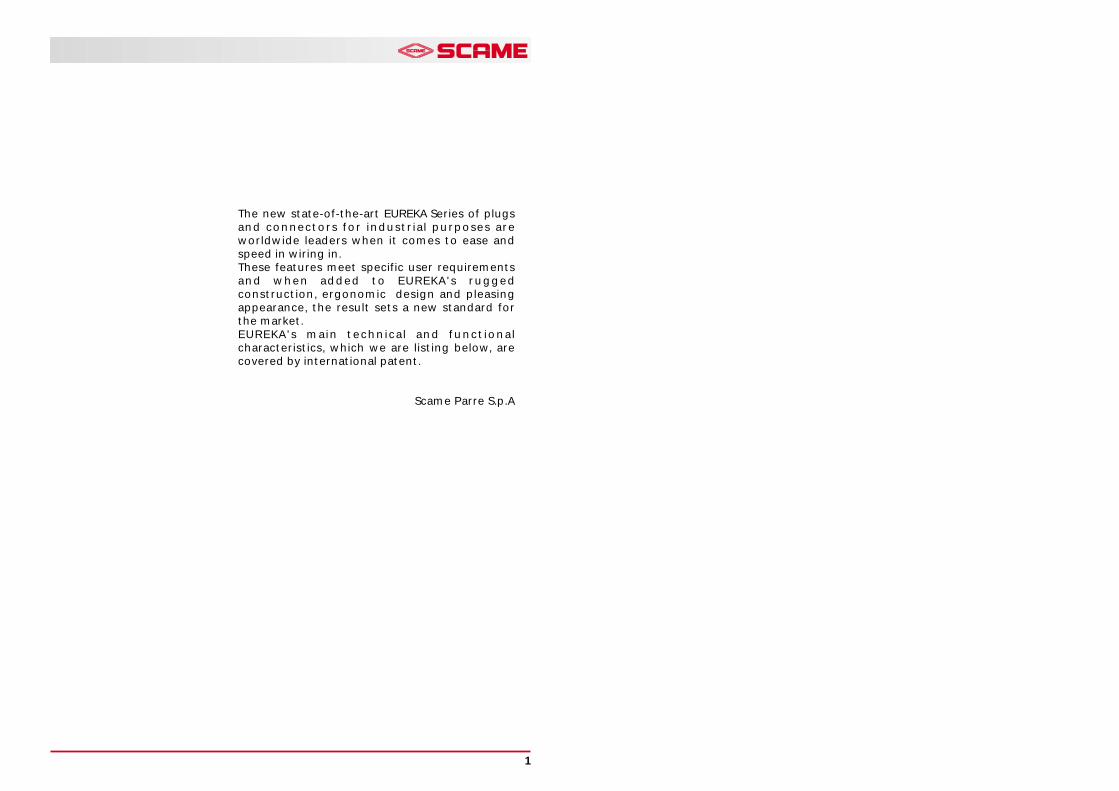
EUREKA SERIES INDUSTRIAL PLUGS ANDCONNECTORSEureka Series industrial plugs and connectors aredesigned for cable-end or stationary connection ofelectrical equipment and comply with IEC(International Electrotechnical Commission) 309-1 and309-2 standard.
- Patented technical features allow quick and easycabling.
- Colour-coded for fast identification of the ratedvoltage
- Different contact configurations ensure preventionof connecting devices of different rated voltages.
- High degree of protection against the ingress ofsolid matter or water through the use of improvedsealing methods.
- High degree of protection against harmful contactssince the earthing contact is the first to beestablished and the last to be broken.
- High resistance to harmful agents such as water, dirt,grease, chemicals.
STANDARDS
PlugEUREKA Series3P+N+E - 16A - 6h - IP44
European standard EN 60 309-1equivalent to IEC 309-1
Plugs, socket-outlets and couplers for industrial purposes
Part 1: General requirements.
European standard EN 60 309-2equivalent to IEC 309-2
Plugs, socket-outlets and couplers for industrial purposes
Part 2: Dimensional interchangeability requirements for pin and contact-tube
accessories of harmonized configurations.ConnectorEUREKA Series3P+N+E - 16A - 6h - IP44
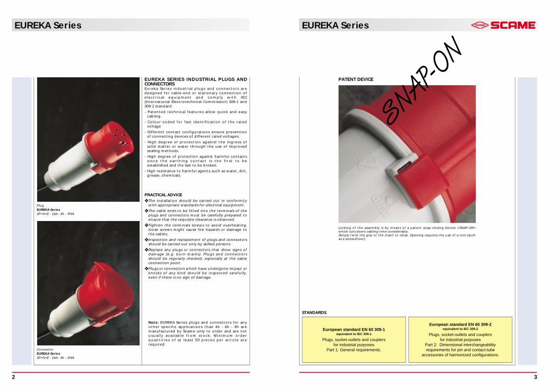
PATENT DEVICE
Locking of the assembly is by means of a patent snap-closing device >SNAP-ON<which cuts down cabling time considerably.Simply twist the grip or the insert to close. Opening requires the use of a tool (suchas a screwdriver).
SNAP-O
N
PRACTICAL ADVICE❖ The installation should be carried out in conformity
with appropriate standards for electrical equipment.
❖ The cable ends to be fitted into the terminals of theplugs and connectors must be carefully prepared toensure that the requisite clearance is observed.
❖ Tighten the terminals screws to avoid overheating,loose screws might cause fire hazards or damage tothe cables.
❖ Inspection and replacement of plugs and connectorsshould be carried out only by skilled persons.
❖ Replace any plugs or connectors that show signs ofdamage (e.g. burn-marks). Plugs and connectorsshould be regularly checked, especially at the cableconnection point.
❖ Plugs or connectors which have undergone impact orknocks of any kind should be inspected carefully,even if there is no sign of damage.
Note: EUREKA Series plugs and connectors for anyother specific applications than 4h - 6h - 9h aremanufactured by Scame only to order and are notusually available from stock. Minimum orderquantities of at least 50 pieces per article arerequired.
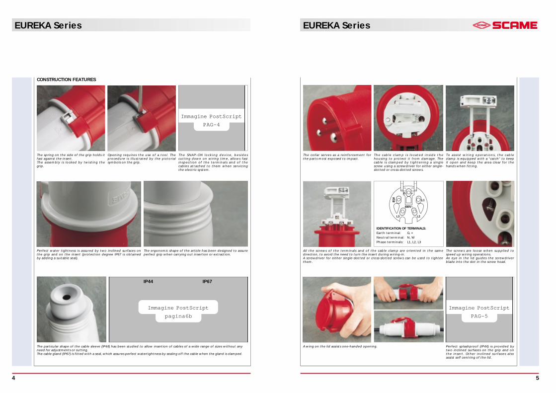
Immagine PostScript
pagina6b
EUREKA Series
5
EUREKA Series
4
Immagine PostScript
PAG-4
The spring on the side of the grip holds itfast against the insert. The assembly is locked by twisting thegrip.
CONSTRUCTION FEATURES
IP44 IP67
Perfect water tightness is assured by two inclined surfaces onthe grip and on the insert (protection degree IP67 is obtainedby adding a suitable seal).
The particular shape of the cable sleeve (IP44) has been studied to allow insertion of cables of a wide range of sizes without anyneed for adjustments or cutting.The cable gland (IP67) is fitted with a seal, which assures perfect watertightness by sealing off the cable when the gland is clamped.
Opening requires the use of a tool. Theprocedure is illustrated by the pictorialsymbols on the grip.
The SNAP-ON locking device, besidescutting down on wiring time, allows fastinspection of the terminals and of thecables attached to them when servicingthe electric system.
The ergonomic shape of the article has been designed to assureperfect grip when carrying out insertion or extraction.
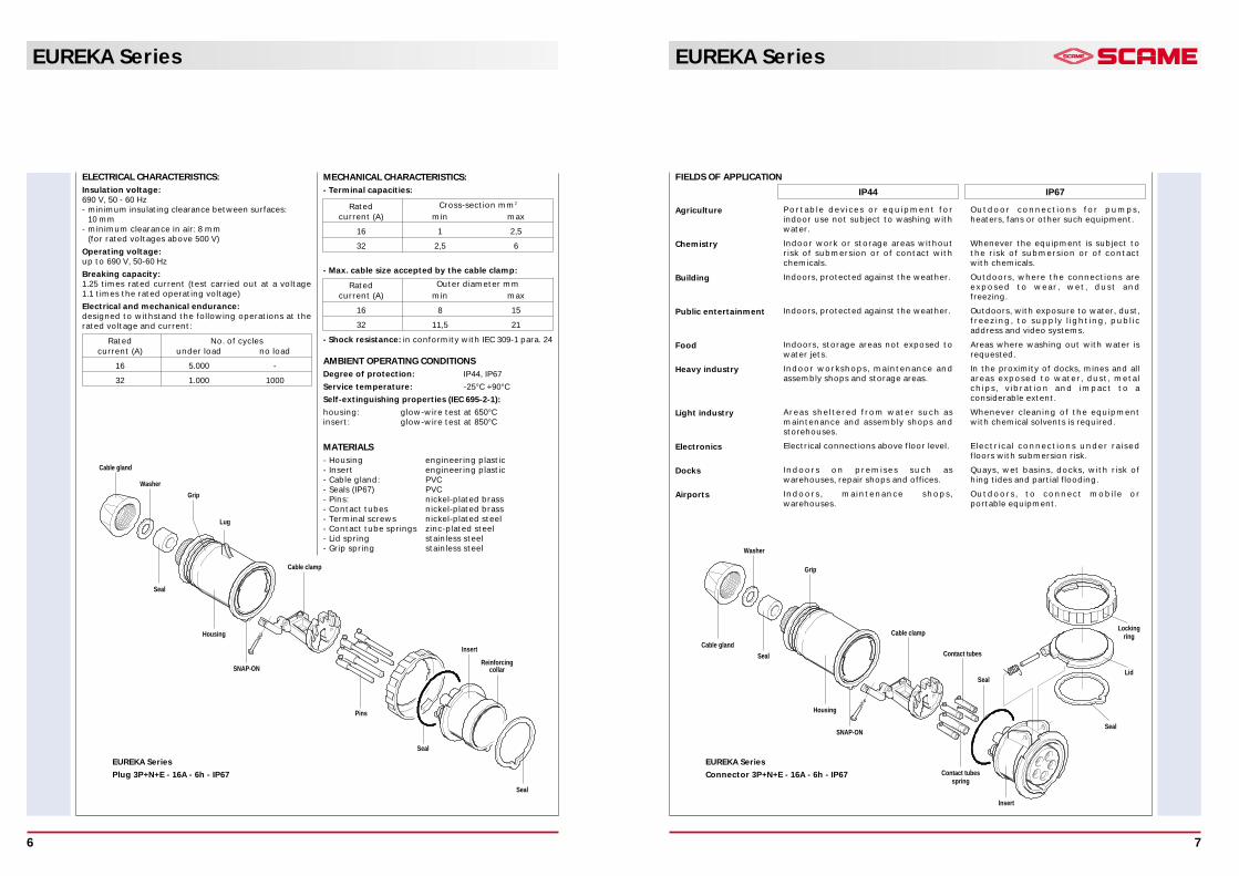
The collar serves as a reinforcement forthe parts most exposed to impact.
L1
L2L3
NW
G =
690V~
All the screws of the terminals and of the cable clamp are oriented in the samedirection, to avoid the need to turn the insert during wiring-in. A screwdriver for either single-slotted or cross-slotted screws can be used to tightenthem.
The cable clamp is located inside thehousing to protect it from damage. Thecable is clamped by tightening a singlescrew using a screwdriver for either single-slotted or cross-slotted screws.
To assist wiring operations, the cableclamp is equipped with a “catch” to keepit open and keep the area clear for thehands when fitting.
Immagine PostScript
PAG-5
The screws are loose when supplied tospeed up wiring operations.An eye in the lid guides the screwdriverblade into the slot in the screw head.
Perfect splashproof (IP44) is provided bytwo inclined surfaces on the grip and onthe insert. Other inclined surfaces alsoassist self centring of the lid.
A wing on the lid assists one-handed opening.
IDENTIFICATION OF TERMINALS:Earth terminal: G, =
Neutral terminal: N, W
Phase terminals: L1, L2, L3
MECHANICAL CHARACTERISTICS:- Terminal capacities:
- Max. cable size accepted by the cable clamp:
- Shock resistance: in conformity with IEC 309-1 para. 24
ELECTRICAL CHARACTERISTICS:Insulation voltage: 690 V, 50 - 60 Hz- minimum insulating clearance between surfaces:
10 mm- minimum clearance in air: 8 mm
(for rated voltages above 500 V)
Operating voltage: up to 690 V, 50-60 Hz
Breaking capacity:1.25 times rated current (test carried out at a voltage1.1 times the rated operating voltage)
Electrical and mechanical endurance:designed to withstand the following operations at therated voltage and current:
EUREKA Series
7
EUREKA Series
6
AMBIENT OPERATING CONDITIONSDegree of protection: IP44, IP67
Service temperature: -25°C +90°C
Self-extinguishing properties (IEC 695-2-1):
housing: glow-wire test at 650°C insert: glow-wire test at 850°C
MATERIALS- Housing engineering plastic- Insert engineering plastic- Cable gland: PVC- Seals (IP67) PVC- Pins: nickel-plated brass- Contact tubes nickel-plated brass- Terminal screws nickel-plated steel- Contact tube springs zinc-plated steel- Lid spring stainless steel- Grip spring stainless steel
FIELDS OF APPLICATION
Agriculture
Chemistry
Building
Public entertainment
Food
Heavy industry
Light industry
Electronics
Docks
Airports
Portable devices or equipment forindoor use not subject to washing withwater.
Indoor work or storage areas withoutrisk of submersion or of contact withchemicals.
Indoors, protected against the weather.
Indoors, protected against the weather.
Indoors, storage areas not exposed towater jets.
Indoor workshops, maintenance andassembly shops and storage areas.
Areas sheltered from water such asmaintenance and assembly shops andstorehouses.
Electrical connections above floor level.
Indoors on premises such aswarehouses, repair shops and offices.
Indoors, maintenance shops,warehouses.
Outdoor connections for pumps,heaters, fans or other such equipment.
Whenever the equipment is subject tothe risk of submersion or of contactwith chemicals.
Outdoors, where the connections areexposed to wear, wet, dust andfreezing.
Outdoors, with exposure to water, dust,freezing, to supply lighting, publicaddress and video systems.
Areas where washing out with water isrequested.
In the proximity of docks, mines and allareas exposed to water, dust, metalchips, vibration and impact to aconsiderable extent.
Whenever cleaning of the equipmentwith chemical solvents is required.
Electrical connections under raisedfloors with submersion risk.
Quays, wet basins, docks, with risk ofhing tides and partial flooding.
Outdoors, to connect mobile orportable equipment.
EUREKA Series
Connector 3P+N+E - 16A - 6h - IP67
EUREKA Series
Plug 3P+N+E - 16A - 6h - IP67
Rated No. of cyclescurrent (A) under load no load
16 5.000 -
32 1.000 1000
Rated Cross-section mm2
current (A) min max
16 1 2,5
32 2,5 6
Rated Outer diameter mm
current (A) min max
16 8 15
32 11,5 21
Seal
Cable gland
Housing
Contact tubesspring
Insert
SNAP-ON
Seal
Insert
Reinforcingcollar
Grip
Cable clamp
Contact tubes
Lid
Seal
Seal
Cable clamp
Grip
Cable gland
Washer
Lug
SNAP-ON
Housing
Seal
Pins
Lockingring
IP44 IP67
Washer
Seal
EUREKA Series
9
EUREKA Series
8
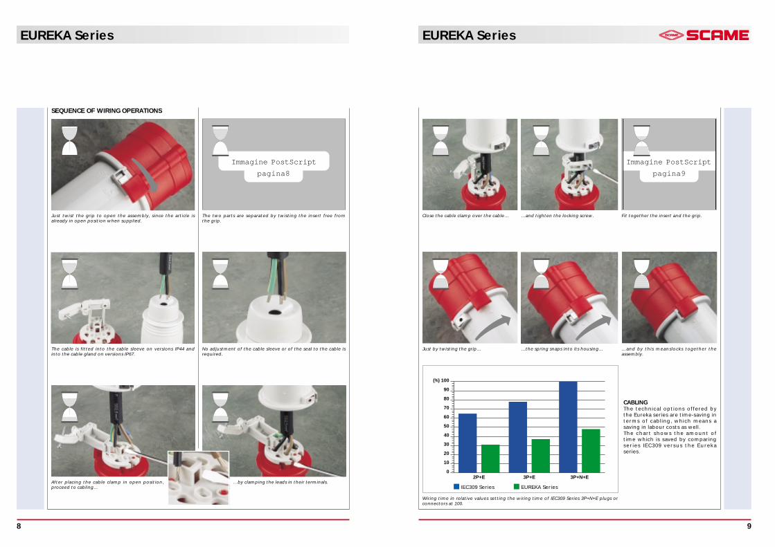
SEQUENCE OF WIRING OPERATIONS
The cable is fitted into the cable sleeve on versions IP44 andinto the cable gland on versions IP67.
No adjustment of the cable sleeve or of the seal to the cable isrequired.
After placing the cable clamp in open position,proceed to cabling…
…by clamping the leads in their terminals.
Just twist the grip to open the assembly, since the article isalready in open position when supplied.
Immagine PostScript
pagina8
The two parts are separated by twisting the insert free fromthe grip.
Immagine PostScript
pagina9
Close the cable clamp over the cable… …and tighten the locking screw. Fit together the insert and the grip.
CABLINGThe technical options offered bythe Eureka series are time-saving interms of cabling, which means asaving in labour costs as well.The chart shows the amount oftime which is saved by comparingseries IEC309 versus the Eurekaseries.
0
10
20
30
40
50
60
70
80
90
(%) 100
2P+E 3P+E 3P+N+E
Just by twisting the grip… …the spring snaps into its housing… …and by this meanslocks together theassembly.
Wiring time in relative values setting the wiring time of IEC309 Series 3P+N+E plugs orconnectors at 100.
IEC309 Series EUREKA Series
COLOUR CODEThe rated operating voltage may be identified by acolour. The colour code is tabulated below:
1) For frequencies over 60 Hz and up to 500 Hz, greencan be used in conjunction with the colour of therated operating voltage, if necessary.
2) In countries where Series II rated currents are used,orange is the distinguishing colour for 125/250V ACand grey for 277V AC.
For any other voltages without colour code, Scamewill supply in RAL 7035 grey.
Clock face position Frequency
Rated operating(h) earth contact (1) ColourPoles
Hzvoltage
16A 63A codeV32A 125A
50 and 60100-130 4 4
200-250 6 6
60 277 5 5 - (5)
380-415 9 9
2P+E 50 and 60 480-500 7 7 - (5)
supply fm.isol.trans 12 12 - (5)
100-300 > 50 - - (4)
>300-500 > 50 2 - (4)
DC>50-250 3 3 - (5)
> 250 8 8 - (5)
100-130 4 4
50 and 60 200-250 9 9
380-415 6 6
60 440-460 (3) 11 11
480-500 7 7 - (5)
3P+E 50 and 60 600-690 5 5
supply fm.isol.trans 12 12 - (5)
50 3803 -
60 440 (2)
100-300 > 50 10 - (4)
>300-500 > 50 2 - (4)
57/100-75/130 4 4
120/208-144/250 9 9
50 and 60 200/346-240/415 6 6
277/480-288/500 7 7 - (5)
3P+N+E 347/600-400/690 5 5
60 250/440-265/460 (3) 11 11
50 220-3803 -
60 250-440 (2)
100-300 > 50 - - (4)
>300-500 > 50 2 - (4)
All rated operating voltages and/orALLfrequencies not covered 1 1 -TYPESby other configurations
Yellow
Blue
Red
Black
from 100 to 130
from 200 to 250
from 380 to 480
from 500 to 690
Rated operatingvoltage
V
EUREKA Series
11
EUREKA Series
10
INDUSTRIAL PLUGS AND SOCKETS FOR RATEDOPERATING VOLTAGES > 50V
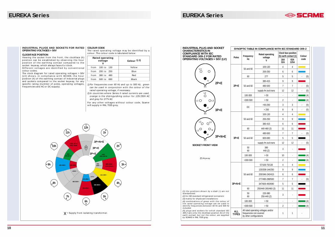
CLOCKFACE POSITIONViewing the socket from the front, the clockface (h)position can be established by observing the hourposition of the earthing contact compared to thesocket keyway, which always faces 6 o’clock.Different voltages are identified by conventionalcolour codes.The clock diagram for rated operating voltages > 50V(LV) shows, in compliance with IEC309, the hourposition (h) of the earthing contact of industrial plugsand sockets compared to the socket keyway, for anyspecific rating (number of poles, operating voltages,frequencies and AC or DC supply).
Colour 1) 2)
(1) the positions shown by a dash (-) are notstandardized.(2) for ISO standard refrigerated containers(3) mainly for shipboard installations(4) combinations of green with the colour ofthe rated operating voltage can be used toidentify frequencies between 60 Hz and 500 Hzincluded.(5) plugs and sockets for which standard IEC309-2 sets only the clockface position (h) of theearth contact, but not the colour, are suppliedby SCAME in RAL 7035 gray.
INDUSTRIAL PLUG AND SOCKETCHARACTERISTICS INCOMPLIANCE WITH IECSTANDARD 309-2 FOR RATEDOPERATING VOLTAGES > 50V (LV)
SYNOPTIC TABLE IN COMPLIANCE WITH IEC STANDARD 309-2
L1
L2
L3
L1
L2 L3
N
L/+
2P+E(*)
(*)
(*)
(*) Keyway
SOCKET FRONT VIEW
3P+E
3P+N+E
x = Supply from isolating transformer.
1h
7h
8h
9h
10h
11h
12h
2h
3h
4h
5h
6h
440V, 60 Hzship instal.
>50V>300-500 Hz
110-130V~
600-660V~
380-415V~
277V~
220-250V~
480-500V~
220-250V~ 380-415V~
>50V100-300 Hz
>50-250V
>250V
380-418V~containers
3P+N+E
3P+E
2P+E
EUREKA Series
13
EUREKA Series
12
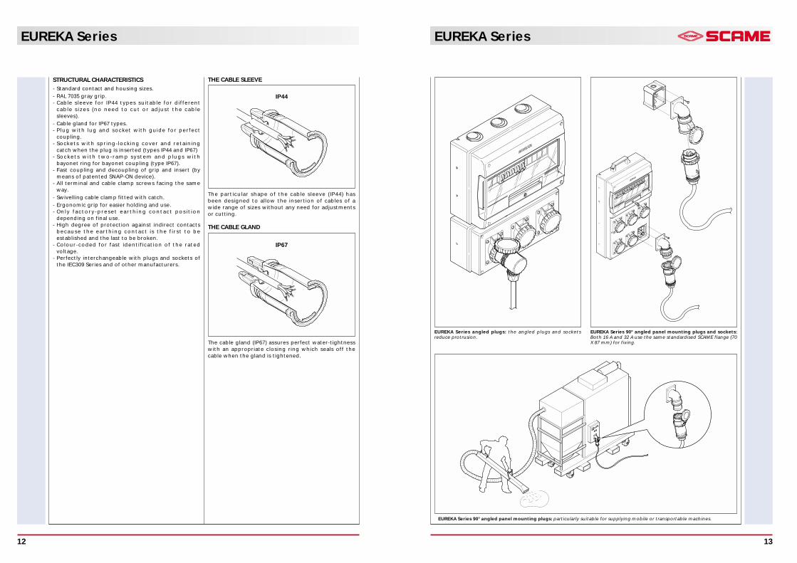
THE CABLE SLEEVE
IP44
The particular shape of the cable sleeve (IP44) hasbeen designed to allow the insertion of cables of awide range of sizes without any need for adjustmentsor cutting.
THE CABLE GLAND
The cable gland (IP67) assures perfect water-tightnesswith an appropriate closing ring which seals off thecable when the gland is tightened.
IP67
STRUCTURAL CHARACTERISTICS
- Standard contact and housing sizes.
- RAL 7035 gray grip.- Cable sleeve for IP44 types suitable for different
cable sizes (no need to cut or adjust the cablesleeves).
- Cable gland for IP67 types.- Plug with lug and socket with guide for perfect
coupling.- Sockets with spring-locking cover and retaining
catch when the plug is inserted (types IP44 and IP67)- Sockets with two-ramp system and plugs with
bayonet ring for bayonet coupling (type IP67).- Fast coupling and decoupling of grip and insert (by
means of patented SNAP-ON device).- All terminal and cable clamp screws facing the same
way.
- Swivelling cable clamp fitted with catch.
- Ergonomic grip for easier holding and use.- Only factory-preset earthing contact position
depending on final use.- High degree of protection against indirect contacts
because the earthing contact is the first to beestablished and the last to be broken.
- Colour-coded for fast identification of the ratedvoltage.
- Perfectly interchangeable with plugs and sockets ofthe IEC309 Series and of other manufacturers.
EUREKA Series 90° angled panel mounting plugs: particularly suitable for supplying mobile or transportable machines.
EUREKA Series angled plugs: the angled plugs and socketsreduce protrusion.
EUREKA Series 90° angled panel mounting plugs and sockets:Both 16 A and 32 A use the same standardised SCAME flange (70X 87 mm) for fixing.
Packing:
STRAIGHT
Poles Hz Volt Colour h
50/60 100-130 4
50/60 200-250 6
50/60 380-415 9
60 277 5
2P+E 50/60 480-500 7
50/60 is. transf. 12
>300-500 >50 2
d.c. >50-250 3
d.c. >250 8
50/60 100-130 4
50/60 200-250 9
50/60 380-415 6
60 440-460 11
50/60 480-500 73P+E
50/60 600-690 5
50/60 is. transf. 1250 38060 440 3
100-300 >50 10
>300-500 >50 2
50/60 100-130 4
50/60 208-250 9
50/60 346-415 6
50/60 480-500 73P+N+E
50/60 600-690 5
60 440-460 1150 38060 440 3
>300-500 >50 2
211.1630 v 211.3230 v 216.1630 v 216.3230 v
211.1633 v 211.3233 v 216.1633 v 216.3233 v
211.1638 v 211.3238 v 216.1638 v 216.3238 v
211.16337 211.32337 216.16337 216.32337
211.16336 211.32336 216.16336 216.32336
211.16333 211.32333 216.16333 216.32333
211.16332 211.32332 216.16332 216.32332
211.16334 211.32334 216.16334 216.32334
211.16338 211.32338 216.16338 216.32338
211.1631 v 211.3231 v 216.1631 v 216.3231 v
211.1634 v 211.3234 v 216.1634 v 216.3234 v
211.1636 v 211.3236 v 216.1636 v 216.3236 v
211.16365 v 211.32365 v 216.16365 v 216.32365 v
211.16366 211.32366 216.16366 216.32366
211.16367 211.32367 216.16367 216.32367
211.16363 211.32363 216.16363 216.32363
211.16364 v 211.32364 v 216.16364 v 216.32364 v
211.16361 211.32361 216.16361 216.32361
211.16362 211.32362 216.16362 216.32362
211.1632 v 211.3232 v 216.1632 v 216.3232 v
211.1635 v 211.3235 v 216.1635 v 216.3235 v
211.1637 v 211.3237 v 216.1637 v 216.3237 v
211.16376 211.32376 216.16376 216.32376
211.16377 211.32377 216.16377 216.32377
211.16375 v 211.32375 v 216.16375 v 216.32375 v
211.16374 v 211.32374 v 216.16374 v 216.32374 v
211.16372 211.32372 216.16372 216.32372
13P+N+E=Packing 10/50 23P+N+E=Packing 10/40
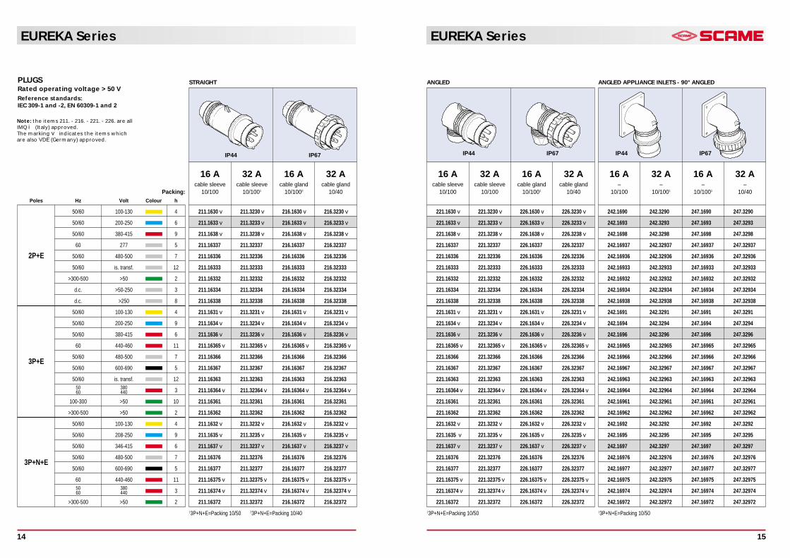
16 A 32 A 16 A 32 Acable sleeve cable sleeve cable gland cable gland
10/100 10/1001 10/1002 10/40
IP44 IP67
PLUGSRated operating voltage > 50 VReference standards: IEC 309-1 and -2, EN 60309-1 and 2
221.1630 v 221.3230 v 226.1630 v 226.3230 v
221.1633 v 221.3233 v 226.1633 v 226.3233 v
221.1638 v 221.3238 v 226.1638 v 226.3238 v
221.16337 221.32337 226.16337 226.32337
221.16336 221.32336 226.16336 226.32336
221.16333 221.32333 226.16333 226.32333
221.16332 221.32332 226.16332 226.32332
221.16334 221.32334 226.16334 226.32334
221.16338 221.32338 226.16338 226.32338
221.1631 v 221.3231 v 226.1631 v 226.3231 v
221.1634 v 221.3234 v 226.1634 v 226.3234 v
221.1636 v 221.3236 v 226.1636 v 226.3236 v
221.16365 v 221.32365 v 226.16365 v 226.32365 v
221.16366 221.32366 226.16366 226.32366
221.16367 221.32367 226.16367 226.32367
221.16363 221.32363 226.16363 226.32363
221.16364 v 221.32364 v 226.16364 v 226.32364 v
221.16361 221.32361 226.16361 226.32361
221.16362 221.32362 226.16362 226.32362
221.1632 v 221.3232 v 226.1632 v 226.3232 v
221.1635 v 221.3235 v 226.1635 v 226.3235 v
221.1637 v 221.3237 v 226.1637 v 226.3237 v
221.16376 221.32376 226.16376 226.32376
221.16377 221.32377 226.16377 226.32377
221.16375 v 221.32375 v 226.16375 v 226.32375 v
221.16374 v 221.32374 v 226.16374 v 226.32374 v
221.16372 221.32372 226.16372 226.32372
13P+N+E=Packing 10/50
16 A 32 A 16 A 32 Acable sleeve cable sleeve cable gland cable gland
10/100 10/100 10/1001 10/40
IP44 IP67
ANGLED
242.1690 242.3290 247.1690 247.3290
242.1693 242.3293 247.1693 247.3293
242.1698 242.3298 247.1698 247.3298
242.16937 242.32937 247.16937 247.32937
242.16936 242.32936 247.16936 247.32936
242.16933 242.32933 247.16933 247.32933
242.16932 242.32932 247.16932 247.32932
242.16934 242.32934 247.16934 247.32934
242.16938 242.32938 247.16938 247.32938
242.1691 242.3291 247.1691 247.3291
242.1694 242.3294 247.1694 247.3294
242.1696 242.3296 247.1696 247.3296
242.16965 242.32965 247.16965 247.32965
242.16966 242.32966 247.16966 247.32966
242.16967 242.32967 247.16967 247.32967
242.16963 242.32963 247.16963 247.32963
242.16964 242.32964 247.16964 247.32964
242.16961 242.32961 247.16961 247.32961
242.16962 242.32962 247.16962 247.32962
242.1692 242.3292 247.1692 247.3292
242.1695 242.3295 247.1695 247.3295
242.1697 242.3297 247.1697 247.3297
242.16976 242.32976 247.16976 247.32976
242.16977 242.32977 247.16977 247.32977
242.16975 242.32975 247.16975 247.32975
242.16974 242.32974 247.16974 247.32974
242.16972 242.32972 247.16972 247.32972
13P+N+E=Packing 10/50
16 A 32 A 16 A 32 A– – – –
10/100 10/1001 10/1001 10/40
IP44 IP67
ANGLED APPLIANCE INLETS - 90° ANGLED
EUREKA Series
14
EUREKA Series
15
Note: the items 211. - 216. - 221. - 226. are allIMQ i (Italy) approved.The marking v indicates the items whichare also VDE (Germany) approved.
Packing:
STRAIGHT
Poles Hz Volt Colour h
50/60 100-130 4
50/60 200-250 6
50/60 380-415 9
60 277 5
2P+E 50/60 480-500 7
50/60 is. transf. 12
>300-500 >50 2
d.c. >50-250 3
d.c. >250 8
50/60 100-130 4
50/60 200-250 9
50/60 380-415 6
60 440-460 11
50/60 480-500 73P+E
50/60 600-690 5
50/60 is. transf. 1250 38060 440 3
100-300 >50 10
>300-500 >50 2
50/60 100-130 4
50/60 208-250 9
50/60 346-415 6
50/60 480-500 73P+N+E
50/60 600-690 5
60 440-460 1150 38060 440 3
>300-500 >50 2
311.1640 v 311.3240 v 316.1640 v 316.3240 v
311.1643 v 311.3243 v 316.1643 v 316.3243 v
311.1648 v 311.3248 v 316.1648 v 316.3248 v
311.16437 311.32437 316.16437 316.32437
311.16436 311.32436 316.16436 316.32436
311.16433 311.32433 316.16433 316.32433
311.16432 311.32432 316.16432 316.32432
311.16434 311.32434 316.16434 316.32434
311.16438 311.32438 316.16438 316.32438
311.1641 v 311.3241 v 316.1641 v 316.3241 v
311.1644 v 311.3244 v 316.1644 v 316.3244 v
311.1646 v 311.3246 v 316.1646 v 316.3246 v
311.16465 v 311.32465 v 316.16465 v 316.32465 v
311.16466 311.32466 316.16466 316.32466
311.16467 311.32467 316.16467 316.32467
311.16463 311.32463 316.16463 316.32463
311.16464 v 311.32464 v 316.16464 v 316.32464 v
311.16461 311.32461 316.16461 316.32461
311.16462 311.32462 316.16462 316.32462
311.1642 v 311.3242 v 316.1642 v 316.3242 v
311.1645 v 311.3245 v 316.1645 v 316.3245 v
311.1647 v 311.3247 v 316.1647 v 316.3247 v
311.16476 311.32476 316.16476 316.32476
311.16477 311.32477 316.16477 316.32477
311.16475 v 311.32475 v 316.16475 v 316.32475 v
311.16474 v 311.32474 v 316.16474 v 316.32474 v
311.16472 311.32472 316.16472 316.32472
13P+N+E=Packing 10/50 23P+N+E=Packing 10/40
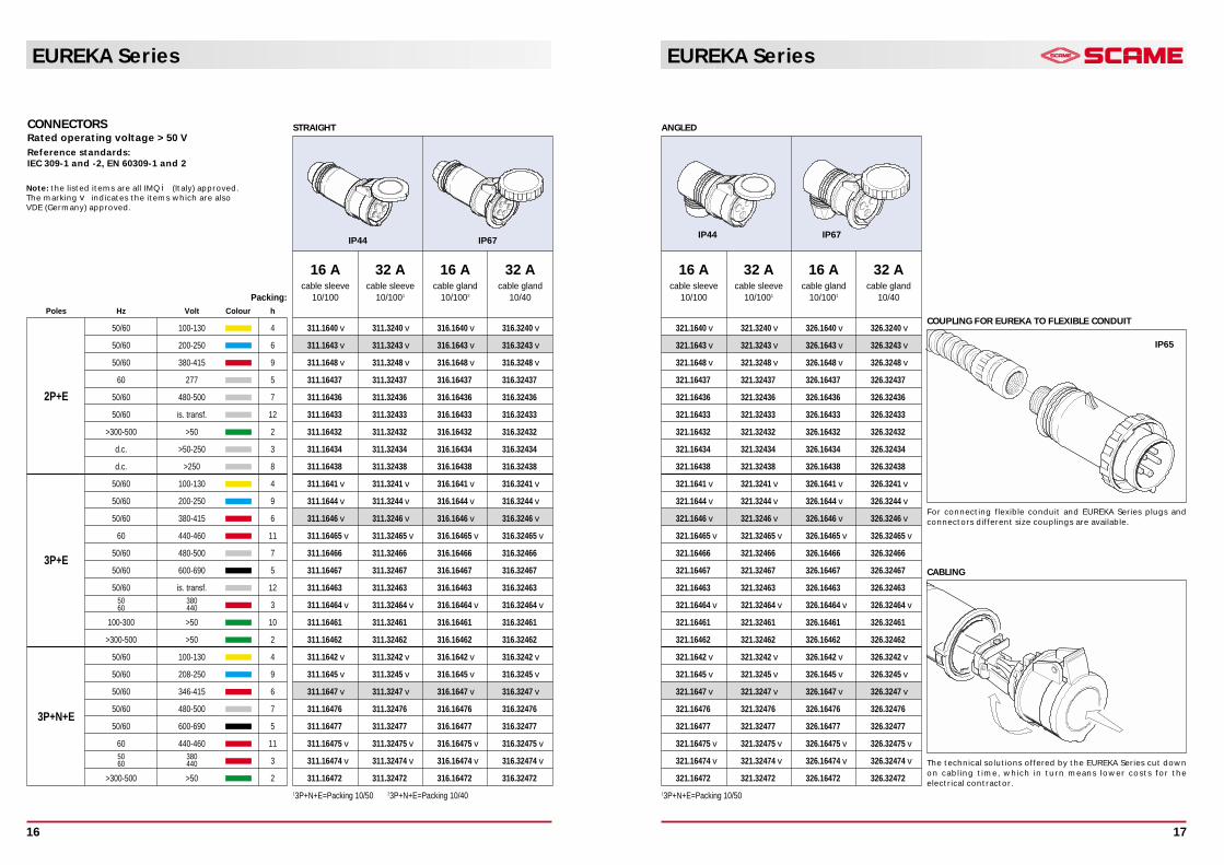
CONNECTORSRated operating voltage > 50 VReference standards: IEC 309-1 and -2, EN 60309-1 and 2
16 A 32 A 16 A 32 Acable sleeve cable sleeve cable gland cable gland
10/100 10/1001 10/1002 10/40
IP44 IP67
ANGLED
321.1640 v 321.3240 v 326.1640 v 326.3240 v
321.1643 v 321.3243 v 326.1643 v 326.3243 v
321.1648 v 321.3248 v 326.1648 v 326.3248 v
321.16437 321.32437 326.16437 326.32437
321.16436 321.32436 326.16436 326.32436
321.16433 321.32433 326.16433 326.32433
321.16432 321.32432 326.16432 326.32432
321.16434 321.32434 326.16434 326.32434
321.16438 321.32438 326.16438 326.32438
321.1641 v 321.3241 v 326.1641 v 326.3241 v
321.1644 v 321.3244 v 326.1644 v 326.3244 v
321.1646 v 321.3246 v 326.1646 v 326.3246 v
321.16465 v 321.32465 v 326.16465 v 326.32465 v
321.16466 321.32466 326.16466 326.32466
321.16467 321.32467 326.16467 326.32467
321.16463 321.32463 326.16463 326.32463
321.16464 v 321.32464 v 326.16464 v 326.32464 v
321.16461 321.32461 326.16461 326.32461
321.16462 321.32462 326.16462 326.32462
321.1642 v 321.3242 v 326.1642 v 326.3242 v
321.1645 v 321.3245 v 326.1645 v 326.3245 v
321.1647 v 321.3247 v 326.1647 v 326.3247 v
321.16476 321.32476 326.16476 326.32476
321.16477 321.32477 326.16477 326.32477
321.16475 v 321.32475 v 326.16475 v 326.32475 v
321.16474 v 321.32474 v 326.16474 v 326.32474 v
321.16472 321.32472 326.16472 326.32472
13P+N+E=Packing 10/50
16 A 32 A 16 A 32 Acable sleeve cable sleeve cable gland cable gland
10/100 10/1001 10/1001 10/40
IP44 IP67
COUPLING FOR EUREKA TO FLEXIBLE CONDUIT
For connecting flexible conduit and EUREKA Series plugs andconnectors different size couplings are available.
CABLING
The technical solutions offered by the EUREKA Series cut downon cabling time, which in turn means lower costs for theelectrical contractor.
IP65
EUREKA Series
16
EUREKA Series
17
Note: the listed items are all IMQ i (Italy) approved.The marking v indicates the items which are also VDE (Germany) approved.

EUREKA Series
19
Flange:Packing:
ANGLED
Poles Hz Volt Colour h
50/60 100-130 4
50/60 200-250 6
50/60 380-415 9
60 277 5
2P+E 50/60 480-500 7
50/60 is. transf. 12
>300-500 >50 2
d.c. >50-250 3
d.c. >250 8
50/60 100-130 4
50/60 200-250 9
50/60 380-415 6
60 440-460 11
50/60 480-500 73P+E
50/60 600-690 5
50/60 is. transf. 1250 38060 440 3
100-300 >50 10
>300-500 >50 2
50/60 100-130 4
50/60 208-250 9
50/60 346-415 6
50/60 480-500 73P+N+E
50/60 600-690 5
60 440-460 1150 38060 440 3
>300-500 >50 2
412.1660 412.3260 417.1660 417.3260
412.1663 412.3263 417.1663 417.3263
412.1668 412.3268 417.1668 417.3268
412.16637 412.32637 417.16637 417.32637
412.16636 412.32636 417.16636 417.32636
412.16633 412.32633 417.16633 417.32633
412.16632 412.32632 417.16632 417.32632
412.16634 412.32634 417.16634 417.32634
412.16638 412.32638 417.16638 417.32638
412.1661 412.3261 417.1661 417.3261
412.1664 412.3264 417.1664 417.3264
412.1666 412.3266 417.1666 417.3266
412.16665 412.32665 417.16665 417.32665
412.16666 412.32666 417.16666 417.32666
412.16667 412.32667 417.16667 417.32667
412.16663 412.32663 417.16663 417.32663
412.16664 412.32664 417.16664 417.32664
412.16661 412.32661 417.16661 417.32661
412.16662 412.32662 417.16662 417.32662
412.1662 412.3262 417.1662 417.3262
412.1665 412.3265 417.1665 417.3265
412.1667 412.3267 417.1667 417.3267
412.16676 412.32676 417.16676 417.32676
412.16677 412.32677 417.16677 417.32677
412.16675 412.32675 417.16675 417.32675
412.16674 412.32674 417.16674 417.32674
412.16672 412.32672 417.16672 417.32672
16 A 32 A 16 A 32 A70x87 84x106 70x87 84x10610/100 10/50 10/100 10/50
IP44 IP67
PANEL MOUNTING SOCKET OUTLETSRated operating voltage > 50 VReference standards: IEC 309-1 and -2, EN 60309-1 and 2
EUREKA Series
18
422.1660 422.3260 427.1660 427.3260
422.1663 422.3263 427.1663 427.3263
422.1668 422.3268 427.1668 427.3268
422.16637 422.32637 427.16637 427.32637
422.16636 422.32636 427.16636 427.32636
422.16633 422.32633 427.16633 427.32633
422.16632 422.32632 427.16632 427.32632
422.16634 422.32634 427.16634 427.32634
422.16638 422.32638 427.16638 427.32638
422.1661 422.3261 427.1661 427.3261
422.1664 422.3264 427.1664 427.3264
422.1666 422.3266 427.1666 427.3266
422.16665 422.32665 427.16665 427.32665
422.16666 422.32666 427.16666 427.32666
422.16667 422.32667 427.16667 427.32667
422.16663 422.32663 427.16663 427.32663
422.16664 422.32664 427.16664 427.32664
422.16661 422.32661 427.16661 427.32661
422.16662 422.32662 427.16662 427.32662
422.1662 422.3262 427.1662 427.3262
422.1665 422.3265 427.1665 427.3265
422.1667 422.3267 427.1667 427.3267
422.16676 422.32676 427.16676 427.32676
422.16677 422.32677 427.16677 427.32677
422.16675 422.32675 427.16675 427.32675
422.16674 422.32674 427.16674 427.32674
422.16672 422.32672 427.16672 427.32672
16 A 32 A 16 A 32 A75x75 75x75 75x75 75x7510/100 10/100 10/100 10/100
IP44 IP67
STRAIGHT - REDUCED FLANGE 75X75
452.1660 452.3260 457.1660 457.3260
452.1663 452.3263 457.1663 457.3263
452.1668 452.3268 457.1668 457.3268
452.16637 452.32637 457.16637 457.32637
452.16636 452.32636 457.16636 457.32636
452.16633 452.32633 457.16633 457.32633
452.16632 452.32632 457.16632 457.32632
452.16634 452.32634 457.16634 457.32634
452.16638 452.32638 457.16638 457.32638
452.1661 452.3261 457.1661 457.3261
452.1664 452.3264 457.1664 457.3264
452.1666 452.3266 457.1666 457.3266
452.16665 452.32665 457.16665 457.32665
452.16666 452.32666 457.16666 457.32666
452.16667 452.32667 457.16667 457.32667
452.16663 452.32663 457.16663 457.32663
452.16664 452.32664 457.16664 457.32664
452.16661 452.32661 457.16661 457.32661
452.16662 452.32662 457.16662 457.32662
452.1662 452.3262 457.1662 457.3262
452.1665 452.3265 457.1665 457.3265
452.1667 452.3267 457.1667 457.3267
452.16676 452.32676 457.16676 457.32676
452.16677 452.32677 457.16677 457.32677
452.16675 452.32675 457.16675 457.32675
452.16674 452.32674 457.16674 457.32674
452.16672 452.32672 457.16672 457.32672
13P+N+E=Packing 10/50
16 A 32 A 16 A 32 A70x87 70x87 70x87 70x8710/100 10/1001 10/1001 10/40
IP44 IP67
90° ANGLED - NORMAL FLANGE 70X87
Note: the items 412. - 417. - 422. - 427. are allIMQ i (Italy) approved.
EUREKA Series
21
EUREKA Series
20
Inlet:Packing:
ANGLED BOX
Poles Hz Volt Colour h
50/60 100-130 4
50/60 200-250 6
50/60 380-415 9
60 277 5
2P+E 50/60 480-500 7
50/60 is. transf. 12
>300-500 >50 2
d.c. >50-250 3
d.c. >250 8
50/60 100-130 4
50/60 200-250 9
50/60 380-415 6
60 440-460 11
50/60 480-500 73P+E
50/60 600-690 5
50/60 is. transf. 1250 38060 440 3
100-300 >50 10
>300-500 >50 2
50/60 100-130 4
50/60 208-250 9
50/60 346-415 6
50/60 480-500 73P+N+E
50/60 600-690 5
60 440-460 1150 38060 440 3
>300-500 >50 2
512.1650 512.3250 517.1650 517.3250
512.1653 512.3253 517.1653 517.3253
512.1658 512.3258 517.1658 517.3258
512.16537 512.32537 517.16537 517.32537
512.16536 512.32536 517.16536 517.32536
512.16533 512.32533 517.16533 517.32533
512.16532 512.32532 517.16532 517.32532
512.16534 512.32534 517.16534 517.32534
512.16538 512.32538 517.16538 517.32538
512.1651 512.3251 517.1651 517.3251
512.1654 512.3254 517.1654 517.3254
512.1656 512.3256 517.1656 517.3256
512.16565 512.32565 517.16565 517.32565
512.16566 512.32566 517.16566 517.32566
512.16567 512.32567 517.16567 517.32567
512.16563 512.32563 517.16563 517.32563
512.16564 512.32564 517.16564 517.32564
512.16561 512.32561 517.16561 517.32561
512.16562 512.32562 517.16562 517.32562
512.1652 512.3252 517.1652 517.3252
512.1655 512.3255 517.1655 517.3255
512.1657 512.3257 517.1657 517.3257
512.16576 512.32576 517.16576 517.32576
512.16577 512.32577 517.16577 517.32577
512.16575 512.32575 517.16575 517.32575
512.16574 512.32574 517.16574 517.32574
512.16572 512.32572 517.16572 517.32572
13P+N+E=Packing 10/40
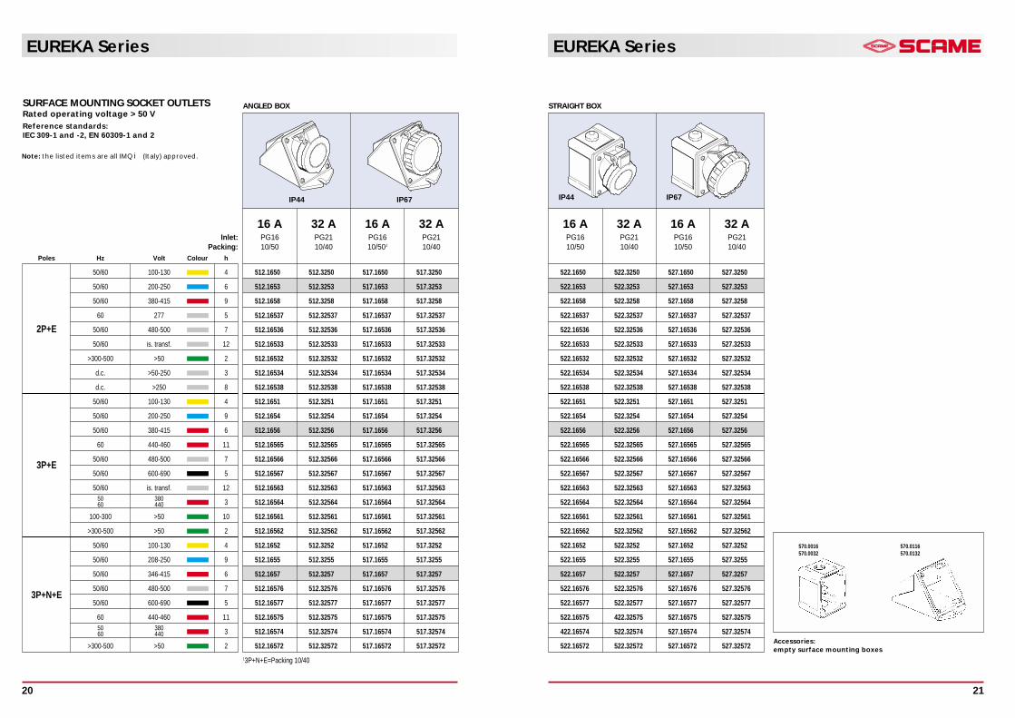
SURFACE MOUNTING SOCKET OUTLETSRated operating voltage > 50 VReference standards: IEC 309-1 and -2, EN 60309-1 and 2
16 A 32 A 16 A 32 APG16 PG21 PG16 PG2110/50 10/40 10/501 10/40
IP44 IP67
522.1650 522.3250 527.1650 527.3250
522.1653 522.3253 527.1653 527.3253
522.1658 522.3258 527.1658 527.3258
522.16537 522.32537 527.16537 527.32537
522.16536 522.32536 527.16536 527.32536
522.16533 522.32533 527.16533 527.32533
522.16532 522.32532 527.16532 527.32532
522.16534 522.32534 527.16534 527.32534
522.16538 522.32538 527.16538 527.32538
522.1651 522.3251 527.1651 527.3251
522.1654 522.3254 527.1654 527.3254
522.1656 522.3256 527.1656 527.3256
522.16565 522.32565 527.16565 527.32565
522.16566 522.32566 527.16566 527.32566
522.16567 522.32567 527.16567 527.32567
522.16563 522.32563 527.16563 527.32563
522.16564 522.32564 527.16564 527.32564
522.16561 522.32561 527.16561 527.32561
522.16562 522.32562 527.16562 527.32562
522.1652 522.3252 527.1652 527.3252
522.1655 522.3255 527.1655 527.3255
522.1657 522.3257 527.1657 527.3257
522.16576 522.32576 527.16576 527.32576
522.16577 522.32577 527.16577 527.32577
522.16575 422.32575 527.16575 527.32575
422.16574 522.32574 527.16574 527.32574
522.16572 522.32572 527.16572 527.32572
16 A 32 A 16 A 32 APG16 PG21 PG16 PG2110/50 10/40 10/50 10/40
IP44 IP67
STRAIGHT BOX
Accessories:empty surface mounting boxes
570.0016570.0032
570.0116570.0132
Note: the listed items are all IMQ i (Italy) approved.
EUREKA Series
23
EUREKA Series
22
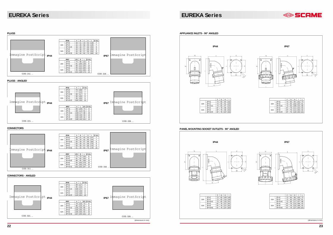
IP44 A B C D L Ø Min.2P+E 46 31 44 53 137 7
16A 3P+E 49 34 50 60 144 73P+N+E 55 39 57 68 160 92P+E 55 39 57 68 170 9
32A 3P+E 55 39 57 68 170 93P+N+E 61 43 63 75 178 10
IP67 ØG B L Ø Min.2P+E 73 75 144 8
16A 3P+E 81 83 150 83P+N+E 88 95 168 102P+E 93 102 178 10
32A 3P+E 93 102 178 103P+N+E 101 102 187 14
PLUGS
PLUGS - ANGLED
CONNECTORS
CONNECTORS - ANGLED
Immagine PostScript
IP44 A B C D L Ø Min.2P+E 30 31 44 53 128 7
16A 3P+E 34 35 50 59 135 73P+N+E 38 38 57 68 150 92P+E 40 38 57 68 159 9
32A 3P+E 40 38 57 68 159 93P+N+E 45 42 62 75 166 10
Immagine PostScriptIP67 ØG B L Ø Min.2P+E 73 98 132 8
16A 3P+E 81 105 139 83P+N+E 88 121 155 102P+E 93 121 164 10
32A 3P+E 93 121 164 103P+N+E 101 130 173 14
Immagine PostScriptIP67 A L ØG Ø Min.2P+E 80 109 73 8
16A 3P+E 88 113 81 83P+N+E 100 117 88 102P+E 100 135 93 10
32A 3P+E 100 135 93 103P+N+E 108 140 101 14
Immagine PostScript
IP44 A L Ø Min.2P+E 70 109 7
16A 3P+E 77 113 73P+N+E 88 117 92P+E 90 135 9
32A 3P+E 90 135 93P+N+E 100 135 10
Immagine PostScript Immagine PostScript
Immagine PostScriptIP67 A L ØG Ø Min.2P+E 78 120 73 8
16A 3P+E 86 125 81 83P+N+E 106 130 88 102P+E 106 150 93 10
32A 3P+E 106 150 93 103P+N+E 107 155 101 14
Immagine PostScript
IP44 A L Ø Min.2P+E 89 117 7
16A 3P+E 95 122 73P+N+E 108 127 92P+E 110 146 9
32A 3P+E 110 146 93P+N+E 120 152 10
COD. 211. ... COD. 216. ...
COD. 221. ... COD. 226. ...
COD. 311. ...COD. 316. ...
COD. 326. ...COD. 321. ...
IP44 IP67
IP44 IP67
IP44 IP67
IP44 IP67
(dimensions in mm)
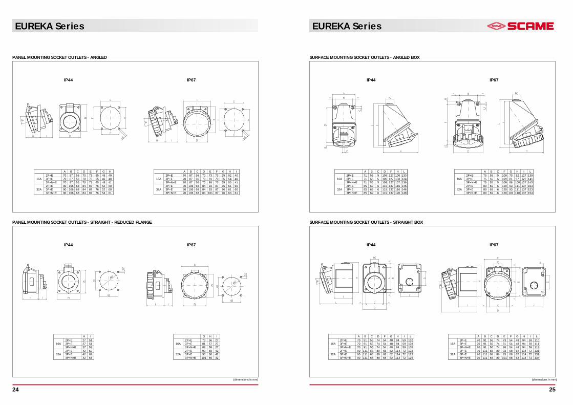
APPLIANCE INLETS - 90° ANGLED
PANEL MOUNTING SOCKET OUTLETS - 90° ANGLED
F G H I2P+E 73 65 83 142
16A 3P+E 73 65 91 1433P+N+E 73 65 97 1442P+E 87 76 99 153
32A 3P+E 87 76 99 1533P+N+E 87 76 107 154
F G H I L2P+E 73 65 93 142 73
16A 3P+E 73 65 102 143 813P+N+E 73 65 109 144 882P+E 87 76 111 153 93
32A 3P+E 87 76 111 153 933P+N+E 87 76 120 154 101
F G H I2P+E 73 65 109 149
16A 3P+E 73 65 116 1503P+N+E 73 65 125 1512P+E 87 76 127 161
32A 3P+E 87 76 127 1613P+N+E 87 76 137 163
F G H I L2P+E 73 65 98 155 73
16A 3P+E 73 65 107 156 813P+N+E 73 65 117 157 882P+E 87 76 123 168 93
32A 3P+E 87 76 123 168 933P+N+E 87 76 127 169 101
(dimensions in mm)
IP44 IP67
IP44 IP67
PANEL MOUNTING SOCKET OUTLETS - ANGLED
PANEL MOUNTING SOCKET OUTLETS - STRAIGHT - REDUCED FLANGE
(dimensions in mm)
A B C D E F G H2P+E 70 87 56 70 73 65 45 40
16A 3P+E 70 87 56 70 73 65 46 403P+N+E 70 87 56 70 73 65 48 412P+E 90 106 68 84 87 76 52 60
32A 3P+E 90 106 68 84 87 76 52 603P+N+E 90 106 68 84 87 76 54 61
IP44 IP67
IP44 IP67
A B C D E F G H I2P+E 70 87 56 70 73 73 65 52 40
16A 3P+E 70 87 56 70 81 73 65 54 403P+N+E 70 87 56 70 88 73 65 55 412P+E 90 106 68 84 93 87 76 61 60
32A 3P+E 90 106 68 84 93 87 76 61 603P+N+E 90 106 68 84 101 87 76 63 61
H I2P+E 27 51
16A 3P+E 27 513P+N+E 27 522P+E 42 62
32A 3P+E 42 623P+N+E 42 63
G H I2P+E 73 56 27
16A 3P+E 81 57 273P+N+E 88 58 272P+E 93 68 42
32A 3P+E 93 68 423P+N+E 101 69 42
EUREKA Series
25
EUREKA Series
24
SURFACE MOUNTING SOCKET OUTLETS - ANGLED BOX
SURFACE MOUNTING SOCKET OUTLETS - STRAIGHT BOX
(dimensions in mm)
IP44 IP67
IP44 IP67
A B C D F H L2P+E 71 56 5 109 127 100 133
16A 3P+E 71 56 5 109 127 103 1343P+N+E 71 56 5 109 127 107 1362P+E 85 69 6 119 137 116 146
32A 3P+E 85 69 6 119 137 116 1463P+N+E 85 69 6 119 137 120 148
A B C F G H I L2P+E 75 55 5 109 73 92 127 139
16A 3P+E 75 55 5 109 81 97 127 1413P+N+E 75 55 5 109 88 100 127 1432P+E 89 69 6 120 93 111 137 153
32A 3P+E 89 69 6 120 93 111 137 1533P+N+E 89 69 6 120 101 118 137 154
A B C D F G H I L2P+E 70 91 56 74 54 48 94 59 102
16A 3P+E 70 91 56 74 54 48 94 59 1033P+N+E 70 91 56 74 54 48 94 59 1052P+E 90 111 68 89 68 62 114 72 123
32A 3P+E 90 111 68 89 68 62 114 72 1233P+N+E 90 111 68 89 68 62 114 72 125
A B C D E F G H I L2P+E 70 91 56 74 73 54 48 94 59 110
16A 3P+E 70 91 56 74 81 54 48 94 59 1113P+N+E 70 91 56 74 88 54 48 94 59 1132P+E 90 111 68 89 93 68 62 114 72 131
32A 3P+E 90 111 68 89 93 68 62 114 72 1313P+N+E 90 111 68 89 101 68 62 114 72 134