Embed Size (px)
Citation preview

1
EUR 23082 EN - 2007
Geoprocessing web services
Simone Gadenz, Tom De Groeve, Luca Vernaccini

2
The Institute for the Protection and Security of the Citizen provides research-based, systems-oriented support to EU policies so as to protect the citizen against economic and technological risk. The Institute maintains and develops its expertise and networks in information, communication, space and engineering technologies in support of its mission. The strong cross-fertilisation between its nuclear and non-nuclear activities strengthens the expertise it can bring to the benefit of customers in both domains. European Commission Joint Research Centre Institute for the Protection and Security of the Citizen Contact information Address: CCR – TP267, Via Fermi 1, 21020 Ispra, Italy E-mail: tom.de-groeve@jrc Tel.: +39-0332786340 Fax: +39-0332785154 http://ses.jrc.it http://www.jrc.cec.eu.int Legal Notice Neither the European Commission nor any person acting on behalf of the Commission is responsible for the use which might be made of this publication.
Europe Direct is a service to help you find answers to your questions about the European Union
Freephone number (*):
00 800 6 7 8 9 10 11
(*) Certain mobile telephone operators do not allow access to 00 800 numbers or these calls may be billed.
A great deal of additional information on the European Union is available on the Internet. It can be accessed through the Europa server http://europa.eu/ JRC 42501 EUR 23082 EN ISSN 1018-5593 Luxembourg: Office for Official Publications of the European Communities © European Communities, 2007 Reproduction is authorised provided the source is acknowledged Printed in Italy

3
Table of Contents 1 Introduction .................................................................................................................................. 5
2 Asgard: solutions based on ESRI ArcInfo Macro Language.......................................................... 7
2.1 Introduction ........................................................................................................................... 7
2.2 AsgardLite ............................................................................................................................. 7
2.3 AsgardSSH ............................................................................................................................ 8
2.4 Asgard ................................................................................................................................. 10
3 SDERunner: solution based on ESRI ArcSDE client Java Application Program Interface (API) . 12
3.1 Introduction ......................................................................................................................... 12
3.2 Geoprocessing primitives ..................................................................................................... 13
3.2.1 Overview ...................................................................................................................... 13
3.3 Modelling subsystem ........................................................................................................... 13
3.3.1 Introduction .................................................................................................................. 13
3.3.2 Neighbourhood model family........................................................................................ 15
3.3.3 Earthquake model family .............................................................................................. 16
3.3.4 Hurricane model family ................................................................................................ 16
3.3.5 GEOSTAT model family .............................................................................................. 19
3.4 The web tier: the SDERunner web interface ......................................................................... 19
4 Future: solutions based on ESRI ArcGISServer .......................................................................... 20
5 Conclusions ................................................................................................................................ 21
6 References .................................................................................................................................. 22
APPENDIX A: SDERunner Package ................................................................................................. 23
Geometric primitives: ASGDPoint, ASGDLine and ASGDPoly ................................................. 23
Managing Spatial Reference: ASGDSpatialReference ................................................................ 23
Managing ArcSDE connections: ASGDSDEConn ...................................................................... 24
Creating and deleting SDE layers: ASGDLayMan ...................................................................... 24
Defining attribute tables: ASGDTableDefs ................................................................................. 25
Using geometries: ASGDGeometry ............................................................................................ 25
Vector and raster spatial analysis: ASGSpatAnalysis and ASGDRasterAnalysis ......................... 26
Managing analysis results ........................................................................................................... 27
Assembling and transforming results .......................................................................................... 28
Managing coordinates: GISCoordinate ....................................................................................... 28
APPENDIX B: SDERunner Web Interface ........................................................................................ 30
runModel.jsp .............................................................................................................................. 30
addSingleData.jsp ....................................................................................................................... 33

4
addMultiData.jsp ........................................................................................................................ 34
deleteData.jsp ............................................................................................................................. 35
updateAttributeValues.jsp .......................................................................................................... 36
APPENDIX C: AsgardXML ver 2.0................................................................................................... 37
Major changes from version 1.0 ..................................................................................................... 37
Sample XML file ........................................................................................................................... 37
XSD documentation ....................................................................................................................... 37

5
1 Introduction The Open Geospatial Consortium, a consortium of industry defining standards for GIS systems, has recently defined web processing services. A Web Processing Service1 (WPS) defines a standardized interface that facilitates the publishing of geospatial processes, and the discovery of and binding to those processes by clients. Processes include any algorithm, calculation or model that operates on spatially referenced data.
A WPS can be configured to offer any sort of GIS functionality to clients across a network, including access to pre-programmed calculations and/or computation models that operate on spatially referenced data. A WPS may offer calculations as simple as subtracting one set of spatially referenced numbers from another (e.g., determining the difference in influenza cases between two different seasons), or as complicated as a tsunami wave propagation model. The data required by the WPS can be delivered across a network, or available at the server.
The Critech action of the Support to External Security unit has been working on web processing services in the context of disaster monitoring and emergency management. Based on the extensive data held in the Spatial Data Infrastructure for External Security (also known as the Digital Map Archive), processing services have been developed for several operational systems.
• The Global Disaster Alert and Coordination System (GDACS) detects new disasters worldwide and runs GIS models to analyze humanitarian consequences.
• The Interactive Disaster Analysis System (IDAS) allows an emergency manager to define an affected area and perform a GIS analysis in and around this area to list vulnerable transport and energy infrastructure and response facilities. IDAS functionality has also been integrated in other systems such as the Health and Disease Information System (HEDIS; an Intranet of DG Health and Consumer Protection) and the MIC Portal (an Intranet for the Monitoring and Information System of DG Environment).
• One component of the FP7 Chorist project calls a GIS model on Critech systems.
Developing operational WPS involves several complementary activities.
• First, the web technology needs to be implemented to expose GIS functionality to the Internet. Currently, there are few off-the-shelve commercial solutions to do this and they are all at early versions. Critech has experimented and developed several implementations of such web technology.
• Second, one must develop the geoprocessing services that are exposed. This involves the establishment of processing chains combining different data sources, applying algorithms and transforming results in appropriate data formats in such a way that it can run in an automatic way without human intervention. Typically this involves designing robust models that can handle data and processing errors.
• Third, the service is deployed in an operational context. Thereby, its functional status must be monitored, the servers must be kept operational and the underlying data must be updated continuously. Performance issues are also critical if the service is publicly accessible and the load balance varies.
Since 2003, Critech has performed research on web based geoprocessing. This was before OGC started work on the Web Processing Service standards. While continuously evaluating the benefits and
1 OGC Specification for Web Processing Service is available at http://www.opengeospatial.org/standards/wps

6
drawbacks of existing (open-source and commercial) GIS software packages, the operational benefits of an ESRI site license drove the development in this area. Early work focused on scripting technologies. In 2007, Critech exploited the Application Program Interfaces (APIs) of ESRI software, in particular ESRI SDE. With the (stable) release of ESRI ArcGIS Server, web geoprocessing becomes an integral part of the software. This new technology will be used by Critech in 2008. While this environment makes it possible to script web services easily (using PHP), the computational and network overhead still makes that the performance of the currently operational web geoprocessing service of Critech is largely better.

7
2 Asgard: solutions based on ESRI ArcInfo Macro Language
2.1 Introduction The most basic way to connect different software systems is through the operating system. Batch or shell scripts can be quite powerful if no alternative program interfaces are available. Because Critech started work on geoprocessing in 2003 using the ESRI software, significant development was done using this simple method.
The basis of this method is the ArcInfo Macro Language (AML), which allows scripting of geoprocessing functions. AML scripts can be called through a batch file. In turn, batch files can be started from Java, VisualBasic programs, .NET, JSP or ASP web server pages. In spite the risks associated with loosely connecting system components through the operating system, this method has been reliable and performing.
2.2 AsgardLite
AsgardLite is a Visual Basic program that is the basis for the Global Disaster Alert and Coordination System (GDACS). GDACS is a system that monitors disaster events autonomously, calls a GIS analysis to calculate affected population and critical infrastructure, and alerts GDACS subscribers if needed (see De Groeve, 2007).
Figure 1. Flow chart of AsgardLite geoprocessing.
Besides geoprocessing, AsgardLite (Figure 1) has components for data scraping (downloading and caching of external data), data management (using several databases), alert algorithms (to determine alert levels) and alerting (email, SMS and fax alerts).
The geoprocessing component of AsgardLite consists of routines to call an AML script through the operating system. The AML script is called with relevant parameters, and an output file is read upon completion.
GDACS database
GDACS Web
application
Simulation component
Simulation XML
AsgardLite
Internet
GIS System
AML Output
Firewall
DMZ
Intranet

8
Figure 2. Screen shot of AsgardLite scraping modules. There are modules for Volcanoes, Tropical Cyclones and Earthquakes.
AsgardLite runs on a schedule (Figure 2) and geoprocessing calls are made when new data is available.
Because it cannot be invoked or exposed as a web service, AsgardLite is not a web processing service per se. However, interactive simulations are possible with a database as interface. A user defines the simulation parameters in an XML file (with an on-line XML editor). When the XML file is saved, it will be checked for changes by AsgardLite. Subsequently, AsgardLite calculates the scenario and publishes the data on a web site. When this process is completed, the user can consult the web site.
This procedure has been put in place for testing purposes. To test the complete system, a strong earthquake event is defined under water, which should trigger a Red alert and the tsunami system. The simulation system does all calculations but does not send out alerts.
2.3 AsgardSSH
One challenge with providing geoprocessing web services is to expose functionality but to protect data and servers. Typically, web applications are put in a “Demilitarized Zone” (DMZ), which is a network zone accessible to the Internet, but separated as much as possible from the corporate network through a firewall. The DMZ should be considered as an unsafe zone, where computers and data are at risk. Therefore, it is custom to put critical data in a Demilitarized Resource Zone (DMRZ), a zone that is more protected, but accessible from the DMZ.
Typically, a web application runs in the DMZ and accesses data in the DMRZ through a firewall. However, geoprocessing processes typically need to access very large databases and produce a small result. Geoprocessing is a “chatty” process in the sense that it accesses the databases much more than non-spatial processes. Because all traffic between DMZ and DMRZ must be analyzed by the firewall, it creates a bottleneck. Therefore, the processing should be done in the same zone as the data, and only the result should be transmitted to the DMZ and the main web application (Figure 3).

9
Figure 3. Flowchart of AsgardSSH geoprocessing
Another reason to move the geoprocessing to the DMRZ (or sometimes even the corporate network) is related to GIS software licenses. More often than not, large organizations such as JRC do not operate with individual software licenses but use site licenses. In this case, one server holds a license server, which is consulted at start-up of GIS software. In practice, this means that all machines running GIS software must be able to connect to the license server. It is unlikely (and it is forbidden in JRC) that a machine from the DMZ can connect to a license server on the corporate network. In Critech, we have two hardware keys dedicated to systems: one on the Intranet (for AsgardLite) and one on the DMRZ (for AsgardSSH and SDERunner).
AsgardSSH implements a technique using SSH (secure shell) network protocol. A web application in the DMZ accepts a geoprocessing request. After verifying the validity of the input parameters, the application opens an SSH connection to a server on the DMRZ and triggers a batch file which runs an AML script. The output of the AML script is read and fed back to the web application. The web application transforms the output into XML compatible with the web service specifications.
The AsgardSSH web application (Figure 3) was developed in .Net and supports multiple processes to be launched in parallel. However, the server license supports only a limited number of simultaneous GIS processes. Therefore, AsgardSSH is in effect limited to running simultaneous 4 analyses.
AsgardSSH is exposed in several ways as a web service:
Web application
AsgardSSH web service
GIS System
AML Output
SSH
Firewall DMRZ DMZ
Figure 4. Example of AsgardSSH web service interface.

10
• SOAP (POST request). An XML request is sent to the server and an XML response is produced. Details about the SOAP web service are published at: http://139.191.254.48/chorist.asmx.
POST /chorist.asmx HTTP/1.1 Host: 139.191.254.48 Content-Type: application/soap+xml; charset=utf-8 Content-Length: length <?xml version="1.0" encoding="utf-8"?> <soap12:Envelope xmlns:xsi="http://www.w3.org/2001/XMLSchema-instance" xmlns:xsd="http://www.w3.org/2001/XMLSchema" xmlns:soap12="http://www.w3.org/2003/05/soap-envelope"> <soap12:Body> <do_nbh1 xmlns="http://tempuri.org/"> <lat>double</lat> <lon>double</lon> </do_nbh1> </soap12:Body> </soap12:Envelope>
• REST (GET request). All parameters are given in a URL.
http://dma.jrc.it/idas/report.aspx?system=internet&model=NBH1&latitude=50.65&longitude=3.866&scenario=<scenario>&bulletinID=1&title=<title>&description=<description>
Currently, AsgardSSH is used in several applications including the Interactive Disaster Analysis System (IDAS) and an FP7 project called Chorist. Both are applications for real-time emergency management. IDAS is operationally used by over 5 Commission Directorate General. The main difference between IDAS and Chorist is that IDAS is a web application and Chorist is a desktop application. Both, however, provide user-friendly tools and a map-based user interface to define a geoprocessing jobs.
2.4 Asgard
Previously, Critech also worked on a more ambitious project for a generic web modelling service referred to as Asgard (see De Groeve and Jacobson, 2006). The purpose of Asgard was to provide a rapid, reliable, flexible and extensible platform for running GIS-based models. Compared to AsgardLite and AsgardSSH, Asgard allows an arbitrary number of servers to be added in its configuration, very much like GRID computing. Furthermore, because Asgard is built with distributable components, it can be distributed over several servers or even organizations. However, while the capabilities of ArcGIS are powerful and many, the performance is disappointingly slow – of the order of tens of seconds to run a model, even on a modern processor. Asgard’s distributed architecture divides the overall functionality into self-contained Java applications that can be deployed in a variety of configurations. The most important effect that this has on performance is due to the ability to deploy multiple instances of the component that actually runs the underlying GIS model: although any one model will take just as long to process, adding a second model-running component allows a second model to be run in parallel, thus doubling the throughput. Some design decisions—such as, to make the components distributable—have led to a more complex result than the equivalent ‘monolithic’ solution. While throughput was virtually unlimited, Asgard’s latency was large (partially due to the poorly performing Axis library for SOAP). This resulted in a

11
stable but slow system. Work on Asgard has been suspended because it was not suited for time-critical applications.
Figure 5. Schematic overview of Asgard components. Each box is a component that can be deployed on a different
machine.

12
3 SDERunner: solution based on ESRI ArcSDE client Java Application Program Interface (API)
3.1 Introduction The ESRI GIS software used in Critech is an extensive software suite with server-client components, many APIs and several ways to use components in custom software programs. One of the most important components is the database tier. The ArcSDE product is a Spatial Data Engine which uses a traditional database (Microsoft SQLServer or Oracle) and gives it spatial processing capabilities. The ArcSDE API exposes these capabilities to software developers.
Critech used the ArcSDE API to create web geoprocessing services. The result was called the SDERunner. SDERunner has several components (Figure 6):
• Geoprocessing primitives. A set of java classes making use of SDE client Java API has been developed for managing spatial data and to perform some basics spatial analysis on them. Due to the lack of raster analysis functions into SDE Java API the raster functions implemented work on top of the Arc/INFO workstation AML scripts. The ultimate purpose was to develop a set of reusable objects to be integrated in different contexts where spatial data management and analysis is required. A Java class developed by Tomer Petel2 was integrated in the application in order to cope with coordinate and distances calculation. The ROME geoRSS package is also included for transforming XML results into geoRSS.
• Modelling subsystem. The geoprocessing building blocks were then assembled in models, each defined for a particular analysis. The models range from simple neighbourhood analyses (with predefined data layers) to complex spatial interpolation and buffering models to determine the impact of tropical cyclones.
• Web tier. Finally, the processing functionality is exposed to the Internet through a web server. A set of JSP pages handle the input of model parameters, the invocation of model and the publishing of results.
Figure 6. SDERunner architecture and building blocks
2 Tomer Petel ([email protected]) - Credits: Calculation routines (direct() and direct_ell()) are based on work done by Ed Williams. Ed's Code is at: http://williams.best.vwh.net/gccalc.htm

13
3.2 Geoprocessing primitives
3.2.1 Overview A series of geoprocessing primitives were developed assembling objects and processes from the different grounding packages. The design of these components focused on identifying reusable components in different models. The intent was to create a set of classes that modellers could easily assemble in models without a deep knowledge of programming and java coding.
The set of classes developed allow to: - Manage objects to store geometric primitives such as points, line and polygons;
- Cope with Spatial references;
- Handle SDE connections;
- Manage SDE layers and relative attribute tables ;
- Perform geometric operations such as buffering, intersection, union, interpolation, etc…
- perform vector and raster spatial analysis, such as raster statistics, feature in polygon, time series, etc..;
- handling of model result as object or XML documents and following XSLT transformations
A more detailed description of the SDERunner package is given in Appendix A at the end of this document.
3.3 Modelling subsystem
3.3.1 Introduction As previously said, the geoprocessing building blocks were assembled at a higher level into models, each defined for a particular analysis. In the modelling subsystem, predefined models can be created and following exposed through a web server (e.g. in Tomcat as jsp pages). Each model expects a well defined set of input parameters. It then pre-processes data and runs geoprocessing jobs. Finally, it presents the result in the requested format.
As today a total of 13 models were implemented (Figure 7); they can be grouped in 4 module families:
- the neighbourhood models (NBH prefix);
- the earthquake models (EQ prefix);
- the hurricane models (HU and BU prefixes);
- the geostat models (GEO prefix)
Each model produces a final outcome in the form of an AsgardXML document that is then transformed depending on the context where the model was invoked in reports, html pages, geoRSS feeds, KML files or maps.
Following a brief explanation of each family and model is given.

14
Figure 7. UML sketch of the geoprocessing model repository

15
3.3.2 Neighbourhood model family The neighbourhood model family collects together the models for performing standard neighbourhood analysis such as any combination of the following tasks:
- Finding all the feature of a layer that are within a polygon
- Finding all the feature of a layer that are closer than a distance to a place
- Finding all the feature of a layer falling within a range distance from a place
- Finding the first n closest feature to a place
The family is made of 9 models, namely:
- NBH1: Generic neighbourhood model at European scale for analysis within 5 km. It requires as parameters the coordinates of the centre of the analysis.
- NBH1_L: Generic neighbourhood model at European scale for analysis larger than 5 km. It requires as parameters the coordinates of the centre of the analysis.
- NBH1_W: Generic neighbourhood model at global scale. It requires as parameters the coordinates of the centre of the analysis.
- NBH2: Generic neighbourhood model at European scale for analysis within 5 km. It requires as parameters the coordinates of the centre and the radius of the analysis.
- NBH2_L: Generic neighbourhood model at European scale for analysis larger than 5 km. It requires as parameters the coordinates of the centre and the radius of the analysis.
- NBH2_W: Generic neighbourhood model at global scale. It requires as parameters the coordinates of the centre and the radius of the analysis.
- NBH3: Generic neighbourhood model at European scale for analysis within 5 km. It requires as parameters the list of coordinates of a polygon.
- NBH3_L: Generic neighbourhood model at European scale for analysis larger than 5 km. It requires as parameters the list of coordinates of a polygon.
- NBH3_W: Generic neighbourhood model at global scale. It requires as parameters the list of coordinates of a polygon.
Figure 8 shows the result of a neighbourhood analysis on a map. The depicted example is a simulation of a NBH2 model with an influence area of 5 km centred on the point 11 degrees longitude and 46 degrees latitude. Starting from these parameters the model builds a polygon representing the affected area and derives the placement information relative to the administrative boundaries (country or province name).
Once the affected area is identified the process extracts all the vulnerable transport and energy infrastructures placed within its boundary and generate a first XML section for affected infrastructure. A following step is dedicated to identify the aid and transport infrastructures placed out of the affected area but as closer as possible to its limit in order to estimate available response facilities (such as hospitals, police stations and fire brigades).
16
Figure 8. Simulation of a NBH2 model
3.3.3 Earthquake model family The implemented EQ models are a set of neighbourhood analysis specifically designed for earthquakes events.
3.3.4 Hurricane model family The hurricane model family is made up of two types of models: one set of model is focused on building the polygon representing the hurricane affected area, while the other’s aim is to run an impact analysis for the event in that area.
The models into the first set (BU models) generate the hurricane affected area polygon through a process that, starting from the hurricane position and wind radii information published at regular time intervals (3 hours) into bulletins, creates a geometrical interpolation of wind radii for each wind class (39,58,74 knots).
Following a detailed description of the process for a hypothetical storm is given. Let us assume that from the information published in bulletins we have the position and the 39mph wind radii values for each of the 4 points depicted in Figure 9 where the points are named with cardinal numbers and the radii with the r1, r2, r3, r4.

17
Figure 9. Representation of information found in bulletins
The affected area polygon interpolation is the result of a two-steps process where first the interpolation of each couple of points is done and then the resulting shapes are merged in a single polygon. In the Figure 10 the result of single interpolation processes for each segment of the hurricane track line (segments between point 1 and 2, 2 and 3, 4 and 4) is shown.
Figure 10. Interpolation of 39 kts wind radii
18
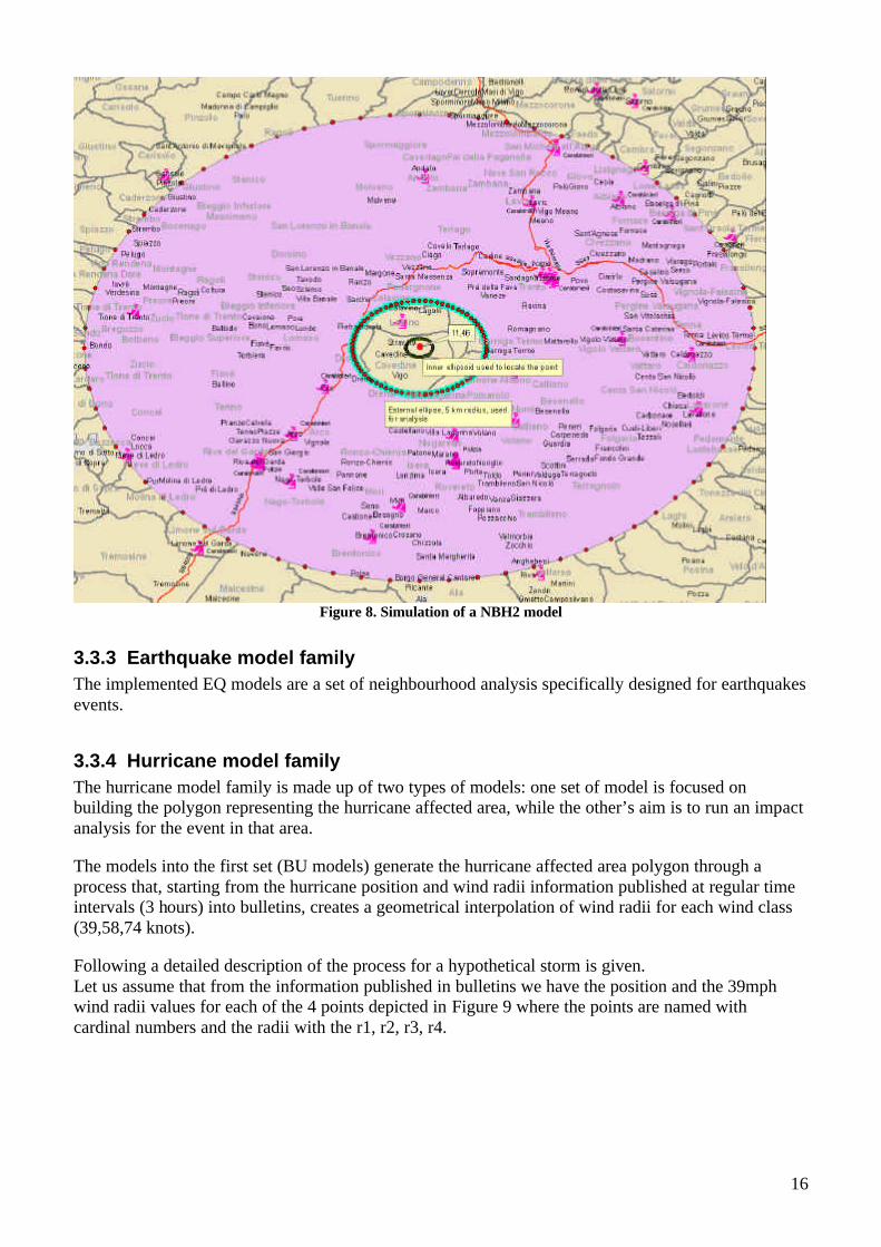
The three polygons are then merged in a single affected area polygon as shown in the Figure 11.
Figure 11. Resulting hurricane affected area
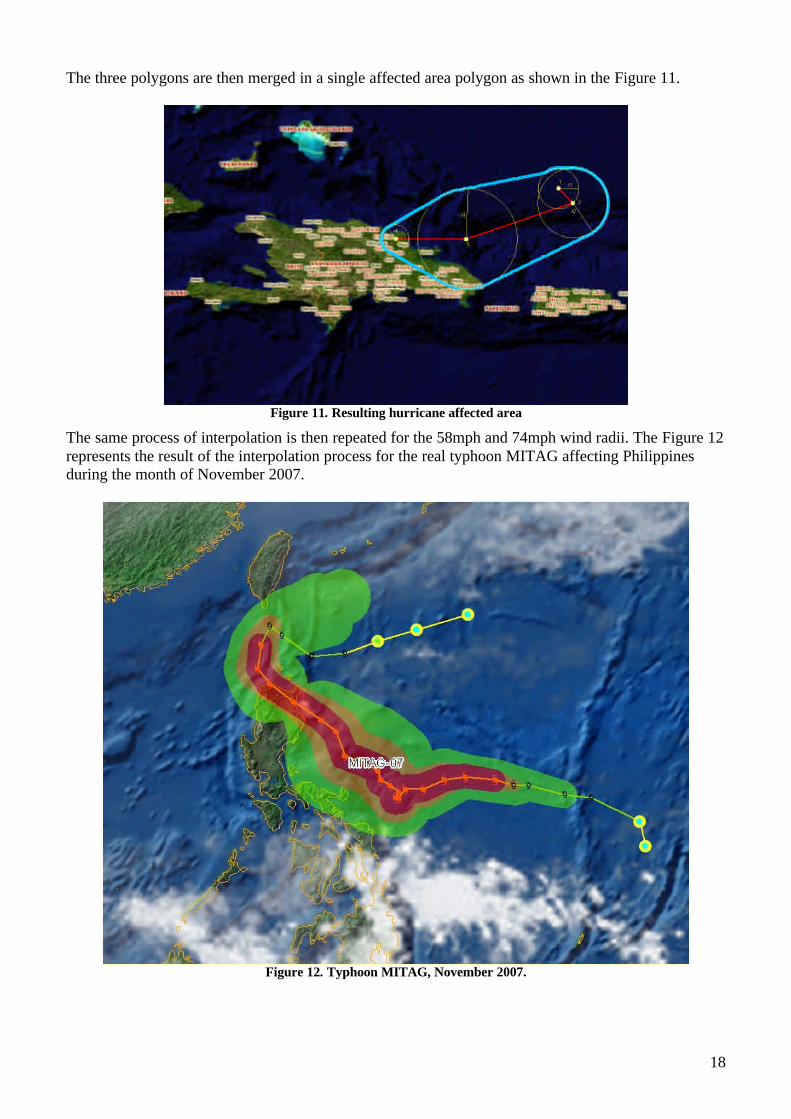
The same process of interpolation is then repeated for the 58mph and 74mph wind radii. The Figure 12 represents the result of the interpolation process for the real typhoon MITAG affecting Philippines during the month of November 2007.
Figure 12. Typhoon MITAG, November 2007.
19
The BU model family is made of two models:
- BU1: Given a set of along track points and relative information such as radii and timespan it returns an interpolated buffer.
- BU2: Given a set of along track points and relative information such as radii and timespan it interpolate a truck buffer and return a list of features into that buffer appending time information to feature attributes.
The other set of analysis groups together a series of three neighbourhood models specifically designed for hurricane events, in particular:
- HU1: Neighbourhood model for comprehensive hurricane impact. It requires as parameters the list of coordinates of the wind buffer.
- HU2: Neighbourhood model for hurricane impact to major cities. It requires as parameters the list of coordinates of the wind buffer.
- HU3: Neighbourhood model for hurricane impact to choose class of cities. It requires as parameters the list of coordinates of the wind buffer.
As the final step of all the hurricane family models a temporal analysis is performed. Combining the geometry of the hurricane with time information coming from bulletins, for each feature resulting from previous NBH model, this process append to its attributes the time range in which it will be interested by the hurricane event.
3.3.5 GEOSTAT model family At the moment this family contains only one model, the GEOSTAT1, for calculating statistics on attribute values of object falling into a specific geographic area. Different statistics are derivable: the sum, the mean and the min and max values.
3.4 The web tier: the SDERunner web interface The SDERunner web tier serves to expose the SDERunner package functionalities to the user by the mean of a RESTful interface. The SDERunner RESTful interface is a set of JSP pages used to launch precompiled geospatial analytical models and to manage geodata into an ArcSDE geodatabase.
The JSP pages so far implemented allow to:
- Run any implemented model and have back the results as xml file or streaming
- Insert geographic data into the SDE repository
- Manage data into repository (delete object and update attribute values).
A detailed description of the pages is given in Appendix B.

20
4 Future: solutions based on ESRI ArcGISServer The new ESRI GIS platform presents a high level of integration between the desktop and server GIS applications. In this new environment the models implemented for desktop use can be directly exposed to the web and they can be consumed by GIS client and by the new ArcGISExplorer, a GoogleEarth-like GIS application distributed for free and integrating geographic data, services and processing model into a 3d environment.
Figure 13 - ArcGis server architecture (courtesy of ESRI)
Having the possibility of fully exploiting the full range of the ArcGIS desktop geoprocessing objects it becomes possible to design and implement a new set of models integrating into a unique platform vector and raster analysis, but also taking advantage of built in network analysis, geocoding and geostatistics functions.
The model will be designed directly into a graphic modelling environment and the modellers do not need to know any programming language at all. The adoption of this platform will then encourage the subdivision of work in specialized job tasks each performed by the most competent person. Some Open Source solution offers good modelling functionalities but all of them are far away from the level of integration reached by ESRI.
It is believed that the enforcement of INSPRE directive and the growing adoption of OGC standards, and in particular of WPS one, will encourage the creation of geoprocessing platforms able to consume distributed geoprocessing components and data.

21
5 Conclusions During the 2007 the modelling infrastructure has been changing to keep the pace with the latest technology. The hardware architecture has been strengthened and optimized in order to make the whole system more reliable and stable. The combination between hardware enhancement and the embracement of the latest technology for the processing unit improved performance and reliability. The uptime of the system has exceeded 99% with only a few failures.
The above described results pushed us to progressively dismiss models based totally on AML and to run those services on the new SDERunner platform. At the same time we moved first steps toward the adoption of the new ArcGIS server platform and in this sense we have already started writing new models reporting components to be integrated into the ArcMap Model Builder platform. The use of the developing reporting component into the new models will make possible to use their results directly into the existing web infrastructure and to plug new models under existent portal and web mapping services.
Future developments will consider an OGC WPS compliant interface to put on top of our models in order to make our geoprocessing services available in a standard way. In this direction we are considering the opportunity of adopting an open source implementation of the WPS standard.

22
6 References • T. DE GROEVE - Global Disaster Alert and Coordination System: More Effective and
Efficient Humanitarian Response - In: The 14th TIEMS Annual Conference 2007 Book of Proceedings, Hotel "Medena", Trogir, Croatia, pages 324-334, Hydrographic Institute of the Republic of Croatia (Publ.), Split - JRC40031
• T. DE GROEVE, M. JACOBSON - Asgard System Description - EUR 22491 EN, PB/2006/IPSC/3341

23
APPENDIX A: SDERunner Package
Geometric primitives: ASGDPoint, ASGDLine and ASGDPoly The SDE Java API has already its own geometric object but the need of a common interface for geometric primitives was felt. Three objects are used to store geometric primitives. The UML class diagram for these three classes is depicted in Figure 14.
Figure 14. Geometric primitive objects
Managing Spatial Reference: ASGDSpatialReference ArcSDE defines the Spatial Reference as the collection of:
- a spatial reference system, either projected or geographic
- an XY domain
- a scale, that is the precision in which the coordinate are stored
Since ArcSDE stores coordinate as long integer values the scale parameter and false XY values are used to transform real world coordinate to stored coordinate values and vice-versa. Hence, to decide the SDE spatial reference several factors should be taken into account:
- the false X and false Y to be used, for a WGS84 these parameters should be set to -180 and -90 to allow the storage of coordinate of the whole globe. Since the SDE returns an errors if the coordinates fall out of the XY domain it is advisable to enlarge the XY domain, say to -210,-120.
- the scale parameter affects the extent of the valid coordinates
- the scale affect the precision of coordinate hence the accuracy of positioning features in the World
A java classes have been developed to cope with Spatial reference. It has two constructors, a void constructor that set the XY domain to (-210,-120,1000000) and the spatial reference system to the 4326 (standard WGS84_GCS), and a constructor to specify the parameters. The UML class diagram for this class is depicted in Figure 15.
Figure 15. Class to manage SRS

24
Managing ArcSDE connections: ASGDSDEConn Connecting to the ArcSDE server requires knowing several parameters, namely:
- name of the server;
- number of the instance (standard is the 5151);
- name of the database;
- user name;
- user password.
Constructors, fields and methods of this class are represented in Figure 16.
Figure 16. SDE connection
Creating and deleting SDE layers: ASGDLayMan The ASGDLayMan is to manage SDE layers, so far only creation and removal of layers have been implemented. Any SDE layer can stor multiple geometric type, that is polygons, lines and points in the same layer, but to see the layer within ArcGIS any layer must store only one type of geometric primitive. For this reason the geometric primitive for which the layer is made has to be specified when invoking the insert2SDEmethod. There are 4 possible types:
- points
- lines and multilines
- polygons
- multipolygons
In order to define a new layer a definition of an attribute table is needed. Attribute table can be defined using th ASGDTableDef classes (see next par.) A UML representation of this class is in Figure 17.

25
Figure 17. SDE layer management
Defining attribute tables: ASGDTableDefs Coping with attribute tables is requested any time a SDE layer is created or queried. The ASGDTableDefs manage definition of attribute table. See Figure 18 for the UML representation of the class.
Figure 18. Definition of attribute table
Using geometries: ASGDGeometry The ASGDGeometry provides functions to store and elaborate geometries. It is to be used to insert geometric shapes into SDE and to perform some geometric calculation within the shape. UML is depicted in Figure 19.
Figure 19. Managing geometries

26
Vector and raster spatial analysis: ASGSpatAnalysis and ASGDRasterAnalysis These classes represent the spatial analysis workhorse of the application. The geographic analysis has been split in two components because of the lack of spatial raster analysis functionalities into the SDE Java API. For that reason the raster analysis is performed using the ESRI Arc/Info workstation engine. So far the implemented functions for vector spatial analysis allow to:
- calculate metric distance between a pair of geographic cords;
- buffering using the SDE buffer method that uses same measure units of the datasets (i.e. it is not possible to define a kilometric buffer on a dataset in geographic coordinates);
- smart buffering using km as measure unit;
- calculate donut shapes around a point;
- select all the Features into a polygon;
- calculate statistics such as the sum, the variance, the mean/minimum/maximum values of one attribute of all the features of one layer falling into a shape.
The UML diagram is in Figure 20.
Figure 20. Spatial analysis engine
The raster spatial analysis works launching an external AML process and intercepting the returned results. For this reason the ASGDRasterAnalysis class is supported by two other classes managing external processes (Figure 21).

27
Figure 21. Raster analysis classes
Managing analysis results The results produced by the spatial analysis procedures are stored in two result objects, one dedicated to the outcome of the vector analysis and the other for the raster results. The need of two objects was felt to cope with the different structure of the results of the two processes. The analysis on vector data produces a series of features made of geometry and of an attribute list.
Figure 22. Managing vector results
The raster analysis instead produces a series of statistics (Figure 23).

28
Figure 23. Managing raster results
Assembling and transforming results The result objects can be assembled into an XML object and then outputted as document in various formats using XSLT transformations (see UML in Figure 24). The structure of the XML object reflect the schema of AsgardXML 2.0 as defined in the XSD described in the Appendix C at the end of this document.
Figure 24. Managing and transforming XML results
Managing coordinates: GISCoordinate The package com.ha.common.gis was included in the application to cope with coordinate transformations, metric distance calculation and different spatial reference systems. The package was available over the web and it has not been fully tested. It was written in java by Tomer Petel ([email protected]), and it is based on the work done by Ed Williams coded in JavaScript. Ed's Code is at: http://williams.best.vwh.net/gccalc.htm The UML diagram of the classes contained in the package are in Figure 25.

29
Figure 25. Coordinate transformations and distance calculation

30
APPENDIX B: SDERunner Web Interface
runModel.jsp
The runModel.jsp page allows running one of the implemented models and having back the results as an XML file or stream.
The syntax to launch a model is the following one:
http://server_name/sderunner/WebRoot/runModel.jsp?model=<name of model>&model_parameters...
where the parameters for each models are depicted in the table below.
Model Required parameter Optional Parameter Return Notes
EQ1 x,y Magnitude, depth, filename
XML or reference to filename
• if filename is provided the jsp returns the URL to the file produced
NBH1 x,y filename
XML or reference to filename
• if filename is provided the jsp returns the URL to the file produced
NBH1_L x,y filename
XML or reference to filename
• if filename is provided the jsp returns the URL to the file produced
NBH1_W x,y filename
XML or reference to filename
• if filename is provided the jsp returns the URL to the file produced
NBH2 x,y,radius filename
XML or reference to filename
• if filename is provided the jsp returns the URL to the file produced
NBH2_L x,y,radius filename
XML or reference to filename
• if filename is provided the jsp returns the URL to the file produced
NBH2_W x,y,radius filename
XML or reference to filename
• if filename is provided the jsp returns the URL to the file produced
NBH3 polygon pairs_sep, coords_sep, filename
XML or reference to filename
• if filename is provided the jsp returns the URL to the file produced
• if no separators are defined the following chars will be considered: ","(coma) for identifying the coordinate pairs and ","(coma) to identify the coordinates within the pairs
• the polygon must be closed, that is the first pair and the lastpair must councide
NBH3_L polygon pairs_sep, coords_sep, XML or • if filename is provided the jsp returns the

31
filename reference to filename
URL to the file produced
• if no separators are defined the following chars will be considered: " "(coma) for identifying the coordinate pairs and ","(coma) to identify the coordinates within the pairs
• the polygon must be closed, that is the first pair and the lastpair must councide
NBH3_W polygon pairs_sep, coords_sep, ilename
XML or reference to filename
• if filename is provided the jsp returns the URL to the file produced
• if no separators are defined the following chars will be considered: ","(coma) for identifying the coordinate pairs and ","(coma) to identify the coordinates within the pairs
• the polygon must be closed, that is the first pair and the lastpair must councide
HU1 polygon pairs_sep, coords_sep, filename
XML or reference to filename
• if filename is provided the jsp returns the URL to the file produced
• if no separators are defined the following chars will be considered: ","(coma) for identifying the coordinate pairs and ","(coma) to identify the coordinates within the pairs
• the polygon must be closed, that is the first pair and the lastpair must councide
HU2 polygon pairs_sep, coords_sep, filename, rainanalysis
XML or reference to filename
• if filename is provided the jsp returns the URL to the file produced
• if no separators are defined the following chars will be considered: " "(coma) for identifying the coordinate pairs and ","(coma) to identify the coordinates within the pairs
• the polygon must be closed, that is the first pair and the lastpair must councide
• set reainanalysis=true for running rainfall analysis into the model
HU3 polygon pairs_sep, coords_sep, filename, rainanalysis
XML or reference to filename
• if filename is provided the jsp returns the URL to the file produced
• if no separators are defined the following chars will be considered: ","(coma) for identifying the coordinate pairs and ","(coma) to identify the coordinates within the pairs
• the polygon must be closed, that is the first pair and the lastpair must councide

32
• set reainanalysis=true for running rainfall analysis into the model
BU1 coords,timespans,radii
layername, colnames, colvalues, sdeinstance, filename
XML or reference to filename
• if filename is provided the jsp returns the URL to the file produced
• coords,timespans,radii are requested as comma separated lists
• coords,timespans,radii must have the same number of elements
• if the layername is specified also the colnames and colvalues must be specified and reflect the attribute table stucture of the specified layer
• if the layer is stored in a SDE instance different from the standard one it is possible to specify the instance parameter in that case the sdeinstance parameter must be a comma separated list of values reflecting this schema (sdeserver,sdeservice,sdedatabasename,sdeuser,sdepassword)
BU2 coords ,timespans, radii, delays, speeds
layername, colnames, colvalues, filename
XML or reference to filename
• if filename is provided the jsp returns the URL to the file produced
• coords,timespans,radii,delays,speeds are requested as comma separated lists
• coords,timespans,radii,delays,speed must have the same number of elements
• if the layername is specified also the colnames and colvalues must be specified and reflect the attribute table stucture of the specified layer
GEOSTAT1
polygon, layername, stat_column, stat_type
pairs_sep,coords_sep, spatial_filter, condition XML
• if no separators are defined the following chars will be considered: ","(blank space) for identifying the coordinate pairs and ","(coma) to identify the coordinates within the pairs
• the polygons (the main shape and the spatial filter) must be closed, that is the first pair and the lastpair must councide

33
addSingleData.jsp
The addSingleData.jsp page allows inserting a new record into an existent ArcSDE layer.
To syntax for using this page is:
http://server_name/sderunner/WebRoot/addSingleData.jsp?shapetype=0|1|2&coordtype=G|g|K|k&coordinates=x,y,x,y,...&layername=name_of_the_layer&attributes=[first_name,first_value,second_name,second_value]
The parameters are better described in the following table.
Name of the parameter
Optional (Y/N) Description Possible values Note
shapetype N
Type of the geometry of the shape to insert. It reflects the geometrical dimension of the features contained into that layer
• 0: point
• 1: line
• 2: polygon
coordtype Y Type of coordinate used
• G/g:geographic
• K: projected(default)
In case the used coordinates are geographic there is a routine to manage the crossing of 180deg horizon
layername N Name of the layer to insert the feature into - Case sensitive
name
coordinates N
Coordinates representing the geometry of the features to insert inside the layer
The coordinates must be specified as x,y pairs, ie:
• point: x,y
• line: x1,y1,x2,y2,.....xn,yn
• poly:x1,y1,x2,y2,.....xn,yn,x1,y1
attributes N List of attributes and values
The attributes mus be inserted as a list of pairs name_of_the_attribute,value separated by a coma and contained into [] brackets

34
addMultiData.jsp
The addMultiData.jsp page allows inserting a series of record in a series of existent ArcSDE layers. It is recommended to use this interface for multiple record insert operations.
The relative syntax is:
http://server_name/sderunner/WebRoot/addMultiData.jsp?shapetype=0;0;0 &coordtype=K;K;G &coordinates=x1,y1;x2,y2;x3,y3 &layername=layer1;layer2;layer3 &attributes=[att_1_1,value_1_1,att_1_2,value_1_2;att_2_1,value_2_1,att_2_2,value_2_2;att_3_1,value_3_1,att_3_2,value_3_2]
The parameters are better described in the following table.
Name of the parameter
Otpional (Y/N) Description Possible values Note
shapetype N
Semicolon separated value list of geometry types of the shape to insert. It reflects the geometrical dimension of the features contained into each layer
• 0: point
• 1: line
• 2: polygon
coordtype Y
Semicolon separated value list of coordinate types used
• G/g:geographic
• K: projected(default)
In case the used coordinates are geographic there is a routine to manage the crossing of 180deg horizon
layername N
Semicolon separated value list of layer names to insert the feature into
- Case sensitive name
coordinates N
Semicolon separated value list of commas eparate value list of coordinate representing the geometry of the features to insert inside the layer
The coordinates must be specified as x,y pairs, ie:
• point: x,y
• line: x1,y1,x2,y2,.....xn,yn
• poly:x1,y1,x2,y2,.....xn,yn,x1,y1
attributes N
Semicolon separated value list of coma separated value list of attributes and values
Any layer's attribute set is represented as in a semicolon separate value list where each of the attribute list must be inserted as a list of pairs name_of_the_attribute,value separated by a coma and contained into [] brackets

35
deleteData.jsp
The deletData.jsp page allows to delete data into one or more ArcSDE layers according to SQL where clause expressed into the parameters..
The syntax for this page is:
http://server_name/sderunner/WebRoot/deleteData.jsp?layername=name1;name2&condition=condition1;condition2
The parameters are better described in the following table.
Name of the parameter
Optional (Y/N) Description Possible values Note
layername N Semicolon separated value list of layer names to insert the feature into
- Case sensitive name
condition N Semicolon separated value list SQL where clauses
Any SQL where operator admitted

36
updateAttributeValues.jsp
The updateAttributeValues.jsp page allows to modify attribute values of features into one or more ArcSDE layers according to SQL where clause expressed into the parameters..
An explanation of the syntax of this page is:
http://server_name/sderunner/WebRoot/updateAttribData.jsp?layername=name1;name2 &condition=condition1;condition2 &attributes=[att_1_1,value_1_1,att_1_2,value_1_2;att_2_1,value_2_1,att_2_2,value_2_2;att_3_1,value_3_1,att_3_2,value_3_2]
The parameters are better described in the following table.
Name of the parameter
Optional (Y/N) Description Possible values Note
layername N Semicolon separated value list of layer names to insert the feature into
- Case sensitive name
condition N Semicolon separated value list SQL where clauses
Any SQL where operator admitted
attributes Semicolon separated value list of coma searated value list of attributes and values
Any layer's attribute set is represented as in a semicolon separate value list where each of the attribute list must be inserted as a list of pairs name_of_the_attribute,value separated by a coma and contained into [] brackets

37
APPENDIX C: AsgardXML ver 2.0
Major changes from version 1.0 • More than one datums node now allowed • datums node collects all the datum of the same vector data source, same raster analysis or
model run • The source of a datums is specified into the attribute of the node:
o id is a unique identifier of the layer within the XML document, o source is the complete reference to the data source (path+filename), o alias is an alias for the data source
• added nodes: title, author, description, link
Sample XML file
XSD documentation Elements author datum datum_id datums description
<?xml version="1.0" encoding="UTF-8"?> <!--Sample XML file generated by XMLSpy v2007 sp2 (http://www.altova.com)--> <episode xsi:noNamespaceSchemaLocation="asgdxml.xsd" xmlns:xsi="http://www.w3.org/2001/XMLSchema-instance"> <episode-id/> <event-id> <namespace/> <event-type/> <event-name/> </event-id> <model-name/> <model-run/> <title/> <author/> <description/> <link/> <datums id="" alias="" source=""> <datum> <datum_id/> <type/> <scalars> <scalar> <name/> <value/> <value-type/> </scalar> </scalars> </datum> </datums> </episode>
38
episode episode-id event-id event-name event-type io link model-name model-run name namespace observation-date real-point scalar scalars title type value value-type
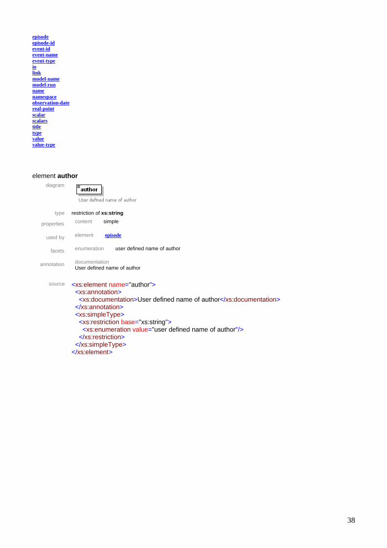
element author
diagram
type restriction of xs:string
properties content simple
used by element episode
facets enumeration user defined name of author
annotation documentation User defined name of author
source <xs:element name="author">
<xs:annotation> <xs:documentation>User defined name of author</xs:documentation> </xs:annotation> <xs:simpleType> <xs:restriction base="xs:string"> <xs:enumeration value="user defined name of author"/> </xs:restriction> </xs:simpleType> </xs:element>

39
element datum
diagram
properties content complex
children datum_id observation-date real-point io type scalars
used by element datums
annotation documentation Resulting information for a record of the layer specified in the parent datums node
source <xs:element name="datum">
<xs:annotation> <xs:documentation>Resulting information for a record of the layer specified in the parent datums node</xs:documentation> </xs:annotation> <xs:complexType> <xs:sequence> <xs:element ref="datum_id"/> <xs:element ref="observation-date" minOccurs="0"/> <xs:element ref="real-point" minOccurs="0"/> <xs:element ref="io" minOccurs="0"/> <xs:element ref="type"> <xs:annotation> <xs:documentation>Geometry type of the feature layer or raster for raster layer</xs:documentation> </xs:annotation> </xs:element> <xs:element ref="scalars"> <xs:annotation> <xs:documentation>Resulting attributes or model analysis for the data source specified in the parent datums node</xs:documentation> </xs:annotation> </xs:element> </xs:sequence> </xs:complexType> </xs:element>

40
element datum_id
diagram
type restriction of xs:byte
properties content simple
used by element datum
facets enumeration 1 enumeration 2 enumeration 3
annotation documentation
Id of the data source within the xml file
source <xs:element name="datum_id"> <xs:annotation> <xs:documentation>Id of the data source within the xml file</xs:documentation> </xs:annotation> <xs:simpleType> <xs:restriction base="xs:byte"> <xs:enumeration value="1"/> <xs:enumeration value="2"/> <xs:enumeration value="3"/> </xs:restriction> </xs:simpleType> </xs:element>
element datums
diagram
properties content complex
children datum
used by element episode
attributes Name Type Use Default Fixed annotation source derived by: xs:string required documentation

41
path to the source layer, alert of reference to the model that produced the result id derived by: xs:byte required documentation unique identifier within the document alias derived by: xs:string required documentation alias of the layer
annotation documentation
Resulting information for a vactor layer
source <xs:element name="datums"> <xs:annotation> <xs:documentation>Resulting information for a vactor layer</xs:documentation> </xs:annotation> <xs:complexType> <xs:sequence maxOccurs="unbounded"> <xs:element ref="datum" maxOccurs="unbounded"> <xs:annotation> <xs:documentation>Resulting information for a record of the vector layer specified in the parent datums node or one of the resulting valued from a model</xs:documentation> </xs:annotation> </xs:element> </xs:sequence> <xs:attribute name="source" use="required"> <xs:annotation> <xs:documentation>path to the source layer, alert of reference to the model that produced the result</xs:documentation> </xs:annotation> <xs:simpleType> <xs:restriction base="xs:string"> <xs:enumeration value="path\to\file"/> </xs:restriction> </xs:simpleType> </xs:attribute> <xs:attribute name="id" use="required"> <xs:annotation> <xs:documentation>unique identifier within the document</xs:documentation> </xs:annotation> <xs:simpleType> <xs:restriction base="xs:byte"> <xs:enumeration value="1"/> <xs:enumeration value="2"/> </xs:restriction> </xs:simpleType> </xs:attribute> <xs:attribute name="alias" use="required"> <xs:annotation> <xs:documentation>alias of the layer</xs:documentation> </xs:annotation> <xs:simpleType> <xs:restriction base="xs:string"> <xs:enumeration value="my feature layer"/> </xs:restriction> </xs:simpleType> </xs:attribute> </xs:complexType> </xs:element>
attribute datums/@source
type restriction of xs:string

42
properties isRef 0 use required
facets enumeration path\to\file
annotation documentation
path to the source layer, alert of reference to the model that produced the result
source <xs:attribute name="source" use="required"> <xs:annotation> <xs:documentation>path to the source layer, alert of reference to the model that produced the result</xs:documentation> </xs:annotation> <xs:simpleType> <xs:restriction base="xs:string"> <xs:enumeration value="path\to\file"/> </xs:restriction> </xs:simpleType> </xs:attribute>
attribute datums/@id
type restriction of xs:byte
properties isRef 0 use required
facets enumeration 1
enumeration 2
annotation documentation unique identifier within the document
source <xs:attribute name="id" use="required">
<xs:annotation> <xs:documentation>unique identifier within the document</xs:documentation> </xs:annotation> <xs:simpleType> <xs:restriction base="xs:byte"> <xs:enumeration value="1"/> <xs:enumeration value="2"/> </xs:restriction> </xs:simpleType> </xs:attribute>
attribute datums/@alias
type restriction of xs:string
properties isRef 0 use required
facets enumeration my feature layer
annotation documentation
alias of the layer
source <xs:attribute name="alias" use="required"> <xs:annotation> <xs:documentation>alias of the layer</xs:documentation> </xs:annotation> <xs:simpleType> <xs:restriction base="xs:string"> <xs:enumeration value="my feature layer"/> </xs:restriction> </xs:simpleType>

43
</xs:attribute>
element description
diagram
type restriction of xs:string
properties content simple
used by element episode
facets enumeration Insert a brief description of the model
annotation documentation User defined description of the analysis
source <xs:element name="description">
<xs:annotation> <xs:documentation>User defined description of the analysis</xs:documentation> </xs:annotation> <xs:simpleType> <xs:restriction base="xs:string"> <xs:enumeration value="Insert a brief description of the model"/> </xs:restriction> </xs:simpleType> </xs:element>

44
element episode
diagram
properties content complex
children episode-id event-id model-name model-run title author description link datums
source <xs:element name="episode"> <xs:complexType> <xs:sequence> <xs:element ref="episode-id"/> <xs:element ref="event-id"/> <xs:element ref="model-name"/> <xs:element ref="model-run"/> <xs:element ref="title"/> <xs:element ref="author"/> <xs:element ref="description"/> <xs:element ref="link"/> <xs:element ref="datums" maxOccurs="unbounded"/> </xs:sequence> </xs:complexType> </xs:element>

45
element episode-id
diagram
type restriction of xs:string
properties content simple
used by element episode
facets enumeration encoded name of the file
annotation documentation Name of the file itself coded according to the schema ModelName_LATMIN_LONMIN_LATMAX_LONMAX where the model name has 3 digit and coordinates are int(coord*10000)
source <xs:element name="episode-id">
<xs:annotation> <xs:documentation>Name of the file itself coded according to the schema ModelName_LATMIN_LONMIN_LATMAX_LONMAX where the model name has 3 digit and coordinates are int(coord*10000) </xs:documentation> </xs:annotation> <xs:simpleType> <xs:restriction base="xs:string"> <xs:enumeration value="encoded name of the file"/> </xs:restriction> </xs:simpleType> </xs:element>

46
element event-id
diagram
properties content complex
children namespace event-type event-name
used by element episode
annotation documentation Identification of the event
source <xs:element name="event-id">
<xs:annotation> <xs:documentation>Identification of the event</xs:documentation> </xs:annotation> <xs:complexType> <xs:sequence> <xs:element ref="namespace"/> <xs:element ref="event-type"/> <xs:element ref="event-name"/> </xs:sequence> </xs:complexType> </xs:element>
element event-name
diagram
type restriction of xs:string
properties content simple

47
used by element event-id
facets enumeration Userdefined name of the event
annotation documentation User define name of the event
source <xs:element name="event-name">
<xs:annotation> <xs:documentation>User define name of the event</xs:documentation> </xs:annotation> <xs:simpleType> <xs:restriction base="xs:string"> <xs:enumeration value="Userdefined name of the event"/> </xs:restriction> </xs:simpleType> </xs:element>
element event-type
diagram
type restriction of xs:string
properties content simple
used by element event-id
facets enumeration Glide list codes for disaster events
annotation documentation Type of the event according to the Glide's list. Value among: CE - Complex Emergency/DR - Drought/EQ - Earthquake/EP - Epidemic/EC - Extratropical Cyclone/ET - Extreme temperature(use CW/HW instead)/FA - Famine(use other "Hazard" code instead)/FR - Fire/FF - Flash Flood/FL - Flood/HT - Heat Wave/IN - Insect Infestation/LS - Land Slide/MS - Mud Slide/OT - Other/ST - SEVERE LOCAL STORM/SL - SLIDE (use LS/ AV/MS instead)/AV - Snow Avalanche/SS - Storm Surge/AC - Tech. Disaster/TO - Tornadoes/TC - Tropical Cyclone/TS - Tsunami/VW - Violent Wind/VO - Volcano/WV - Wave/Surge(use TS/SS instead)/WF - Wild fire
source <xs:element name="event-type">
<xs:annotation> <xs:documentation>Type of the event according to the Glide's list. Value among: CE - Complex Emergency/DR - Drought/EQ - Earthquake/EP - Epidemic/EC - Extratropical Cyclone/ET - Extreme temperature(use CW/HW instead)/FA - Famine(use other "Hazard" code instead)/FR - Fire/FF - Flash Flood/FL - Flood/HT - Heat Wave/IN - Insect Infestation/LS - Land Slide/MS - Mud Slide/OT - Other/ST - SEVERE LOCAL STORM/SL - SLIDE (use LS/ AV/MS instead)/AV - Snow

48
Avalanche/SS - Storm Surge/AC - Tech. Disaster/TO - Tornadoes/TC - Tropical Cyclone/TS - Tsunami/VW - Violent Wind/VO - Volcano/WV - Wave/Surge(use TS/SS instead)/WF - Wild fire</xs:documentation> </xs:annotation> <xs:simpleType> <xs:restriction base="xs:string"> <xs:enumeration value="Glide list codes for disaster events"/> </xs:restriction> </xs:simpleType> </xs:element>
element io
diagram
type restriction of xs:string
properties content simple
used by element datum
facets enumeration i
source <xs:element name="io"> <xs:simpleType> <xs:restriction base="xs:string"> <xs:enumeration value="i"/> </xs:restriction> </xs:simpleType> </xs:element>
element link
diagram
type restriction of xs:string
properties content simple
used by element episode
facets enumeration link to the file or to a rendering web page
annotation documentation URL to the XML file or to a rendering page
source <xs:element name="link">
<xs:annotation> <xs:documentation>URL to the XML file or to a rendering page</xs:documentation> </xs:annotation> <xs:simpleType> <xs:restriction base="xs:string"> <xs:enumeration value="link to the file or to a rendering web page"/> </xs:restriction> </xs:simpleType> </xs:element>

49
element model-name
diagram
type restriction of xs:string
properties content simple
used by element episode
facets enumeration Insert model name
annotation documentation Name of the model
source <xs:element name="model-name">
<xs:annotation> <xs:documentation>Name of the model</xs:documentation> </xs:annotation> <xs:simpleType> <xs:restriction base="xs:string"> <xs:enumeration value="Insert model name"/> </xs:restriction> </xs:simpleType> </xs:element>
element model-run
diagram
type restriction of xs:string
properties content simple
used by element episode
facets enumeration Insert model run date/time
annotation documentation Date of the analysis
source <xs:element name="model-run">
<xs:annotation> <xs:documentation>Date of the analysis</xs:documentation> </xs:annotation> <xs:simpleType> <xs:restriction base="xs:string"> <xs:enumeration value="Insert model run date/time"/> </xs:restriction> </xs:simpleType> </xs:element>
element name
diagram
type restriction of xs:string
properties content simple

50
used by element scalar
annotation documentation
Name of the attribute
source <xs:element name="name"> <xs:annotation> <xs:documentation>Name of the attribute</xs:documentation> </xs:annotation> <xs:simpleType> </xs:simpleType> </xs:element>
element namespace
diagram
type restriction of xs:string
properties content simple
used by element event-id
facets enumeration CRITECH
annotation documentation CRITECH
source <xs:element name="namespace">
<xs:annotation> <xs:documentation>CRITECH</xs:documentation> </xs:annotation> <xs:simpleType> <xs:restriction base="xs:string"> <xs:enumeration value="CRITECH"/> </xs:restriction> </xs:simpleType> </xs:element>
element observation-date
diagram
type restriction of xs:string
properties content simple
used by element datum
facets enumeration Insert obs-date
source <xs:element name="observation-date"> <xs:simpleType> <xs:restriction base="xs:string"> <xs:enumeration value="Insert obs-date"/> </xs:restriction> </xs:simpleType> </xs:element>

51
element real-point
diagram
type xs:boolean
properties content simple
used by element datum
source <xs:element name="real-point" type="xs:boolean"/> element scalar
diagram
properties content complex
children name value value-type
used by element scalars
annotation documentation Attribute name, type and value
source <xs:element name="scalar">
<xs:annotation> <xs:documentation>Attribute name, type and value</xs:documentation> </xs:annotation> <xs:complexType> <xs:sequence> <xs:element ref="name"> <xs:annotation> <xs:documentation>Name of the attribute or of the raster analysis performed</xs:documentation> </xs:annotation> </xs:element> <xs:element ref="value"> <xs:annotation> <xs:documentation>Value of the attribute or result of the raster analysis</xs:documentation> </xs:annotation> </xs:element> <xs:element ref="value-type"/> </xs:sequence> </xs:complexType> </xs:element>
52
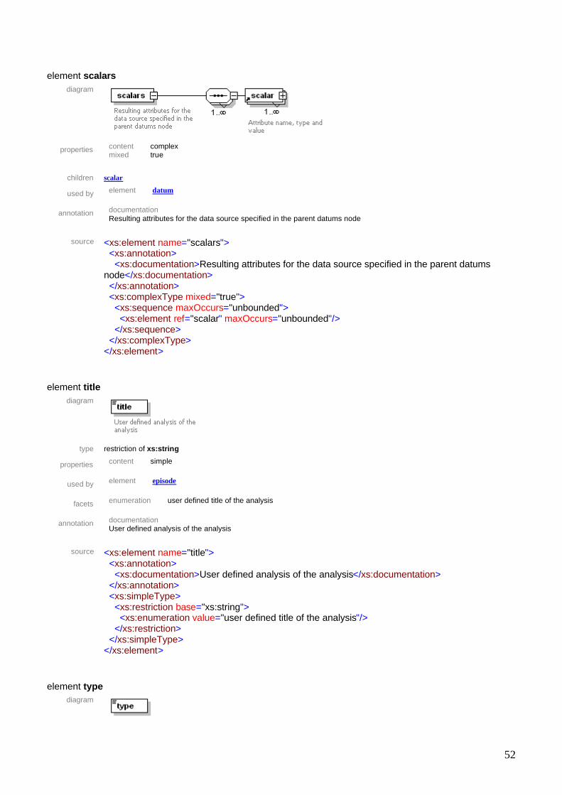
element scalars
diagram
properties content complex
mixed true
children scalar
used by element datum
annotation documentation Resulting attributes for the data source specified in the parent datums node
source <xs:element name="scalars">
<xs:annotation> <xs:documentation>Resulting attributes for the data source specified in the parent datums node</xs:documentation> </xs:annotation> <xs:complexType mixed="true"> <xs:sequence maxOccurs="unbounded"> <xs:element ref="scalar" maxOccurs="unbounded"/> </xs:sequence> </xs:complexType> </xs:element>
element title
diagram
type restriction of xs:string
properties content simple
used by element episode
facets enumeration user defined title of the analysis
annotation documentation User defined analysis of the analysis
source <xs:element name="title">
<xs:annotation> <xs:documentation>User defined analysis of the analysis</xs:documentation> </xs:annotation> <xs:simpleType> <xs:restriction base="xs:string"> <xs:enumeration value="user defined title of the analysis"/> </xs:restriction> </xs:simpleType> </xs:element>
element type
diagram

53
type restriction of xs:string
properties content simple
used by element datum
facets enumeration Polygon
source <xs:element name="type"> <xs:simpleType> <xs:restriction base="xs:string"> <xs:enumeration value="Polygon"/> </xs:restriction> </xs:simpleType> </xs:element>
element value
diagram
type restriction of xs:string
properties content simple
used by element scalar
facets enumeration enumeration 0 enumeration 0.0 enumeration 0.0280459965199 enumeration 040 enumeration 040007 enumeration 08 enumeration 1.2980916106 enumeration 1119 enumeration 121056.0 enumeration 2.38000390043e+013 enumeration 249400560.0 enumeration 35 enumeration 4 enumeration 66 enumeration 72554.0 enumeration 92714.0 enumeration Cesena enumeration Forlì-Cesena enumeration ITA enumeration ITA040 enumeration Italia enumeration Shape
annotation documentation
Value of the attribute
source <xs:element name="value"> <xs:annotation> <xs:documentation>Value of the attribute</xs:documentation> </xs:annotation> <xs:simpleType> <xs:restriction base="xs:string"> <xs:enumeration value=" "/> <xs:enumeration value="0"/> <xs:enumeration value="0.0"/> <xs:enumeration value="0.0280459965199"/> <xs:enumeration value="040"/> <xs:enumeration value="040007"/> <xs:enumeration value="08"/> <xs:enumeration value="1.2980916106"/>

54
<xs:enumeration value="1119"/> <xs:enumeration value="121056.0"/> <xs:enumeration value="2.38000390043e+013"/> <xs:enumeration value="249400560.0"/> <xs:enumeration value="35"/> <xs:enumeration value="4"/> <xs:enumeration value="66"/> <xs:enumeration value="72554.0"/> <xs:enumeration value="92714.0"/> <xs:enumeration value="Cesena"/> <xs:enumeration value="Forlì-Cesena"/> <xs:enumeration value="ITA"/> <xs:enumeration value="ITA040"/> <xs:enumeration value="Italia"/> <xs:enumeration value="Shape"/> </xs:restriction> </xs:simpleType> </xs:element>
element value-type
diagram
type restriction of xs:string
properties content simple
used by element scalar
facets enumeration Coords enumeration Double enumeration Geometry enumeration Integer enumeration OID enumeration SmallInteger enumeration String
annotation documentation
Original datatype of the attribute
source <xs:element name="value-type"> <xs:annotation> <xs:documentation>Original datatype of the attribute</xs:documentation> </xs:annotation> <xs:simpleType> <xs:restriction base="xs:string"> <xs:enumeration value="Coords"/> <xs:enumeration value="Double"/> <xs:enumeration value="Geometry"/> <xs:enumeration value="Integer"/> <xs:enumeration value="OID"/> <xs:enumeration value="SmallInteger"/> <xs:enumeration value="String"/> </xs:restriction> </xs:simpleType> </xs:element>

55

56
European Commission EUR 23082 EN – Joint Research Centre – Institute for the Protection and Security of the Citizen Title: Web Geoprocessing Services Author(s): Simone Gadenz, Tom De Groeve, Luca vernaccini Luxembourg: Office for Official Publications of the European Communities 2007 – 58 pp. – 21 x 30 cm EUR – Scientific and Technical Research series – ISSN 1018-5593 Abstract Since 2003, Critech has performed research on web based geoprocessing. This was before OGC started work on the Web Processing Service standards. While continuously evaluating the benefits and drawbacks of existing (open-source and commercial) GIS software packages, the operational benefits of an ESRI site license drove the development in this area. Early work focused on scripting technologies. In 2007, Critech exploited the Application Program Interfaces (APIs) of ESRI software, in particular ESRI SDE. With the (stable) release of ESRI ArcGIS Server, web geoprocessing becomes an integral part of the software. This new technology will be used by Critech in 2008. This document reports on the status of the work.

57
How to obtain EU publications Our priced publications are available from EU Bookshop (http://bookshop.europa.eu), where you can place an order with the sales agent of your choice. The Publications Office has a worldwide network of sales agents. You can obtain their contact details by sending a fax to (352) 29 29-42758.

58
The mission of the JRC is to provide customer-driven scientific and technical support for the conception, development, implementation and monitoring of EU policies. As a service of the European Commission, the JRC functions as a reference centre of science and technology for the Union. Close to the policy-making process, it serves the common interest of the Member States, while being independent of special interests, whether private or national.