Embed Size (px)
Citation preview

MORGAN STATE UNIVERSITY
SCHOOL OF ARCHITECTURE AND PLANNING
LECTURE III
Dr. Jason E. Charalambides
Euler Column Buckling Theory;Effects of Residual Stresses
2
What is Residual Stress?
Although Steel is considered to be homogenous material, the process of fabrication allows portions of an element to form differently than others. Rolled shapes may go through the rollers hot or cold For cold rolled, it is understood that
the steel is exposed to stresses that bring it into its plastic region to have permanent deformation. When an element is stressed to the point that it deforms and it does not return to its original form, portion of the energy that was received remains within it. That is translated to a stress that is carried within the structure of that element. That is residual stress.
3
What is Residual Stress?
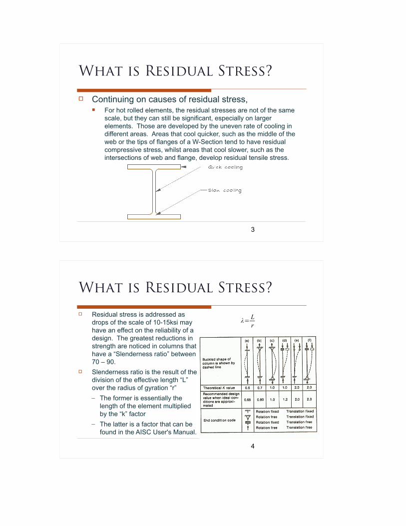
Continuing on causes of residual stress, For hot rolled elements, the residual stresses are not of the same
scale, but they can still be significant, especially on larger elements. Those are developed by the uneven rate of cooling in different areas. Areas that cool quicker, such as the middle of the web or the tips of flanges of a W-Section tend to have residual compressive stress, whilst areas that cool slower, such as the intersections of web and flange, develop residual tensile stress.
4
What is Residual Stress?
Residual stress is addressed as drops of the scale of 10-15ksi may have an effect on the reliability of a design. The greatest reductions in strength are noticed in columns that have a “Slenderness ratio” between 70 – 90.
Slenderness ratio is the result of the division of the effective length “L” over the radius of gyration “r” – The former is essentially the
length of the element multiplied by the “k” factor
– The latter is a factor that can be found in the AISC User's Manual.
λ= Lr

5
Qualities of Different Shapes Some shapes are more practical to fabricate Some shapes have better response to compressive loads Some shapes handle bending better
6
Qualities of Different Shapes Other advantages / disadvantages:
Round columns have less surface to paint or fireproof Round columns have constanr “r” and “I” values They have better torsional resistance and less resistance to
wind loads Square or round columns are more economical and efficient
unless moments play an important role, especially in larger structures
Hollow columns are easier to keep clean, but also easier to be exposed to corrosion over W, S, or T shapes

7
Buckling
Main difference of a compressive axially loaded member over a tensile axially loaded member is “buckling.” That is the “loss of compressive
load carrying capacity resulting from a change in the geometric formation of a member”
A slight defect, or a slight eccentricity, may generate the deflection that will lead to a column's failure
NY City Transit released photos of Cortlandt St sta5on the week of 24 September 2001. Subway columns are buckled from the impact, near the center of the sta5on.All of this is gone.Source: hEp://www.columbia.edu/~brennan/abandoned/Cort-‐damage-‐09.jpg
8
Buckling
Design equation: The ultimate axial load is equal
or less than the factored nominal strength
Pu≤Φ Pn

9
Strength of Isolated Columns Euler's solution to
theoretical elastic behavior:– Based on the following
assumptions: The column is pin connected It is perfectly straight Load is perfectly axial Behaves elastically and does
not yield No residual stresses Bends and buckles about a
principal axis w/out torsion.
Pu≤Φ Pn
10
Strength of Isolated Columns
Euler's elastic buckling: The buckled shape resembles ½ a
sinusoidal distribution.
The buckling load Pe is proportional to the Moment of Inertia of the element
The buckling load is inversely proportional to the square value of the length of the element ( )• The longer the element the more
susceptible to buckling
Buckling is proportional to the Young's modulus of elasticity but independent of the yield strength of the material (Fy)
PE=π 2E IL2
π2 E IL2
L2

11
Consider the Effects of Axial Load on a W Shape
X & Y are Principal Axes
I_max = Ix (Strong Axis) Higher Moment of Inertia
I_min = Iy (Weak Axis) Lower Moment of Inertia
Buckling will be about the (y) weak axis, unless the weak axis is restrained.
12
Consider the Effects of Axial Load on a W Shape
π 2 EI xL2
π 2 EI yL2

13
Addressing Euler's Buckling Load w.r.t. Stress
Stress can be viewed as Load (P) divided by Area (A) If we divide both sides of Euler's equation by Area →
But since the radius of gyration (r)is equal to the square root of moment of inertia (I) divided by area (A)...
Thus Euler's elastic buckling stress is:
PEA = π
2 E IAL2
r=√ IAF E=
π 2 E
( Lr )2
r2= IAΟR
ΟRF E=π2 E r2
L2
14
Bringing Back the Factor of Boundary Conditions
π 2 E
( K Lr )2

15
Load Deflection Behavior
The Length “L” divided by the radius of gyration “r” is the slenderness ration of a column
By plotting a graph of the stress in the ordinates and the slenderness ratio in the abscissa...
r minimum corresponds to I minimum
(L/r) max corresponds to r min Weaker axis of W section (lower
I) controls in buckling
π 2E
( Lr )2
16
Load – Deflection Behavior
Effects of deflection The column bends as soon as it is
loaded, i.e. buckling is not an instantaneous effect.
There is already stress in the column before loading.
Based on Elastic theory (material does not yield) P is asymptotic to PE. No loss of strength due to deflection
In reality material yields, and the additional bending stress from deflection causes earlier yielding and loss of strength
Small deflection → little loss of strength, and vice versa
PE=π 2E IL2

17
Effects of Load Eccentricity Effects of eccentricity
(eccentrically applied loading) are identical to the effects of Δ0
18
Definition and Effects of Residual Stresses Residual stress definition
They are developed within a member during manufacturing. They are self equilibrating (their sum is zero) as they exist in the
absence of any external loading. They are generated by:
Uneven cooling of hot rolled elements Uneven cooling of welded built up elements Cold forming or cambering of members Punching, shearing, or cutting Welding at specific points
Effect Varying behavior at specific points, areas, or along an axis
Localized
Along entire length

19
Causes for Residual Stress
Cooling of Rolled Shapes The uneven rate of cooling of the
cross section. Member is allowed to coll slowly.
Some portions (e.g. flange tips) cool quicker because they have more surface exposed to air
Typically residual stresses are: Quick cool → Compressive Slow cool → Tensile
Residual stresses are normal, not shear stresses
Residual stresses are higher on welded shapes than rolled shapes
σ resmax≈10ksi tο15ksi∫ σres dA=0
20
The Stump Column Test
Residual stresses reduce the stiffness of a member Investigated by testing a
“stub column,” i.e. too short to buckle.
If there are no residual stresses, all fibers of the cross section yield simultaneously when the applied load reaches
• ...i.e. when the applied stress reaches P
A=F y
A×F y

21
The Stump Column Test
Residual stresses reduce the stiffness of a member If residual stresses are present
the first parts of the element that will yield are the tips of the flanges.
Then the effect will extend further beyond the tips of the flanges and the central portion of the web
And eventually the whole section will yield
Although the maximum load will still be , the load deflection curve is not the same
P=A×F y
22
Using the Tangent Modulus
The P vs Δ curve.. Can be replotted in the
form of average applied stress vs strain.
Et is a measure of the cross section's average stiffness, considering that portions of the cross section are yielded, while others are still elastic
σ avg=PA=average applied stress
ε= ΔL0
=applied strain

23
Effect of Residual Stresses on Column Strength
Consider a column that is initially perfectly straight The buckling load can be obtained using the “tangent
modulus theory” that was just discussed. The buckling load can be computed using Euler's
equation, but replacing E with Et. The resulting buckling load is referred to as
“Tangent Modulus buckling load” Similarly we can define the
“Tangent Modulus buckling stress” This leads to two classes of buckling:
• Elastic, and• Inelastic
Pt=π 2 Et I
(K×L)2
F t=PtA
=π 2 Et
( K×Lr )
2
24
Elastic / Inelastic Buckling
Elastic No yielding of the cross section
occurs prior to buckling and Et=E at buckling
predicts buckling
Inelastic Yielding occurs on portions of the
cross section prior to buckling and there is loss of stiffness.
predicts buckling
π 2 E
( K×Lr )
2
F t=P tA
π 2 Et
( K×Lr )
2F E=π 2 E
( K×Lr )
2
FT=π 2 ET
( K×Lr )
2

25
Strength of Columns
The discussion that was held until now indicates that the strength of a column is dependent upon the following: Slenderness End restraint Eccentricity (loading or form) Yielding and Residual stresses
All of the above factors need to be addressed in order to determine the strength of a real column but there are two approaches to do that: Experiments (we shall not engage in this!) Numerical Analysis
K factorλ= Lr
Must consider variability in these factors
26
Numerical Method of Analysis
The AISC provides a series of equations that allow us to compute the column strength:
Nominal compressive strengthwhere Ag is Area gross, and Fcr is the critical or buckling stress
Design compressive strengthwhere Φ is the factor of safety and it is equal to 0.9
Criterion for design
Pn=Ag×Fcr
ΦPn=Φ×Ag×F cr
Pu≤Φ×Pn

27
Numerical Method of Analysis
The AISC provides a series of equations that allow us to compute the column strength:
Nominal compressive strengthwhere Ag is Area gross, and Fcr is the critical or buckling stress
Design compressive strengthwhere Φ is the factor of safety and it is equal to 0.9
Criterion for design
Pn=Ag×Fcr
ΦPn=Φ×Ag×F cr
Pu≤Φ×Pn
28
Computing the Nominal Compressive strength
The definition is: for Euler's buckling Stress
When OR → Inelastic Buckling
(E3-2)
When OR → Elastic Buckling
(E3-3) For elastic buckling we adopt 0.877 times the Euler's formula, accounting for geometric imperfections.
Note that Fcr is independent of Fy
F E=π 2 E
( KLr )2
KLr
≤4.71√ EF y
F y
Fe≤2.25
Fcr=[0.658( FyF E)]F yKLr
>4.71√ EF y
F y
Fe>2.25
F cr=0.877Fe

29
The Red Line for Elastic / Inelastic
Inelastic Buckling
Note: As KL/r→ 0 Fcr→Fy
Elastic Buckling
Fcr=[0.658( FyF E)]F y=[0.658(F y
π2E
(KLr )2)]F y
Fcr=0.877FE=0.877π 2 E
( KLr )2
30
The Red Line for Elastic / Inelastic
Taking the limit: for for 36 and 50 grade steel
→ 36 ksi gives 133.7
→ 50 ksi gives 113
Take a typical column e.g W12x53, of Lu=12' and r=2.48”. With K of 1.0 this W section will give KL/r=58. In either of the grades of steel this column will buckle in the inelastic range
KLr
=4.71√ EF y
4.71√ 29,000ksi36ksi=133.681
4.71√ 29,000ksi50ksi=113.432

31
Relation of Critical Stress and Slenderness Ratio
At
Thus
The transition from elastic to inelastic occurs at an applied axial compression stress of 0.39Fy
4.71√ EF y
.877 FE0.668(KLr )
2 F y
π2E
F E=π 2 E
( KLr )2
KLr =4.71√ EF y
F E=π 2 E
( KLr )2=π2 E F y
4.712 E=0.44F y
F y
F E=2.25
Fcr=0.877FE=0.877∗.44 F y=0.39Fy
32
Basic Procedures for Analysis
Given the shape, the K factor, the Length and the type of steel can we determine the Φpn?
Well, …..
Fcr depends uponKL/r and Fy, The r we chose is the weaker one →(KL/r) max controls
Compute (KL/r)x and (KL/r)y, and larger will govern
ΦPn=Φ×Ag×F cr

Wide Flange Shape subjected to axial loadingProblem Statement:Determine the capacity in axial loading of the given W shape. The element is pinned at top and bottom withno intermediate bracing, therefore having an unbraced length of 15ft in both directions.Use A992 steel
Area Ag 15.8in2:= Young's Modulus of Elasticity E 29000ksi:=
Bolt diameter db 0.875in:=Length: Lu 15ft:=
radius of gyration y ry 2.56in:= Yield Stress: Fy 50ksi:=
radius of gyration x rx 4.37in:= Ultimate Strength: Fu 65ksi:=
K factor K 1:= Factor of Safety phi ϕ 0.9:=
Solution Method 1: Using Chapter E Equations:1) Determining the governing slenderness ratio
λxK Lu⋅
rx:=
15ft 12⋅inft
4.37inλx 41.19=
λyK Lu⋅
ry:=
15ft 12⋅inft
2.56inλy 70.313=
r min rx ry, ( ):= r 2.56 in⋅= governing radius of gyration
The above was already obvious but it was carried on just to "academicallly" justify the numbers
2) Calculating Euler's Buckling Stress
FEπ2 E⋅
K Lu⋅
r
2:=
3.142 29000⋅ ksi
15ft 12⋅inft
2.56in
2FE 57.894 ksi⋅=
3) Determining if the buckling will be elastic or inelastic.
Buckling ifK Lu⋅
r
4.71EFy
≤ "Inelastic", "Elastic",
:= Buckling "Inelastic"=
Alternatively we can also follow the process below:
FyFE
0.864= Buckling ifFyFE
2.25≤ "Inelastic", "Elastic",
:= Buckling "Inelastic"=
4) Calculating the Buckling Stress (Fcr) and the load capacity of the section:
Fcr 0.658
Fy
FE
Fy⋅:= 0.658
50ksi
57.89ksi
50⋅ ksi Fcr 34.832 ksi⋅=
ΦPn ϕ Ag⋅ Fcr⋅:= 0.9 15.8⋅ in2 34.832⋅ ksi ΦPn 495.314 kip⋅=

Solution Method 2: Using Table 4-22:1) Determining the governing slenderness ratio
λyK Lu⋅
ry:=
16ft 12⋅inft
2.56inλy 70.313=
2) Using table we locate the KL/r valuecorresponding to the Fy used for factrized criticalstress:
The value indicated would be between 31.1 and31.4. Let's take 31.3
ΦFcr 31.3ksi:=
Note: From our previous calculations:
Fcr 34.832 ksi⋅=
Therefore:
ϕ Fcr⋅ 31.349 ksi⋅=
3) Calculating the capacity of the element:
ΦPn ϕ Ag⋅ Fcr⋅:=
0.9 15.8⋅ in2 34.832⋅ ksi
ΦPn 495.314 kip⋅=

Solution Method 3:Using Table 4-1 for W shapes pp 4-12 to4-23:Oh you will love this one! All you needis the unbraced length and the shape: