Embed Size (px)
Citation preview

-
..
..
..
..
..,......,.,...........-,.l-..~,.l-
=
E
CONTENTS
1. PARTS OF THE INSTRUMENT .................. 1
2. FEATURES................................... 4
3. SPECIFICATIONS. . . . . . . . . . . . . . .. . . . . . . . . . . . . .. 54. STANDARD EQUIPMENT. . . . . . . . . . . . . . . . . . . . . .. 85. LIETZ SYSTEM S3 STREAMLINED SURVEYING
SOLUTIONS. .. . . . . . . . . . . . . . . . . . . . . . . . . . . . . . .. 96. POWER SUPPLIES ............................. 16
7. DISPLAY SYMBOLS ........................... 18
8. KEY FUNCTIONS. . . . . . . . . . . . . . . . . . . . . . . . . . . . .. 199. INTERNAL SWITCHES ......................... 22
10. OPERATION................. . .. . . . . '. . . . . . . . . . 2310.1 PREPARATION FOR ANGLE MEASUREMENT.. 23
10.1.1 Battery. No. 6651-01: Mounting and check .. 2310.1.2 Compensation of zenith angle ............. 2410.1.3 Centering the SET4A by adjusting tripod
leg length. . . . . . . . . . . . . . . . . . . . . . . . . . . . . . 2510.1.4 Focusing .. . . . . . . . . . . . . . . . . . . . . . . . . . . . . 25
10.2 ANGLE MEASUREMENT. . . . . . . . . . . . . . . . . . . . 2610.2.1 Automatically indexing vertical circle ....... 26
10.2.2 Angle measurement. . . . . . . . . . . . . . . . . . . . . . 2710.2.3 Setting the horizontal circle to a required
value ......................... . . . . . . . . 2810.2.4 Repetition of angles . . . . . . . . . . . . . . . . . . . . . 29
10.3 PREPARATION FOR DISTANCEMEASUREMENT. . . . . . . . . . . . . . . . . . . . . . . . . . . 31
10.3.1 Prism constant correction. . . . . . . . . . . . . . . . . 3110.3.2 Atmospheric correction .................. 32
10.3.3 Earth-curvature and refraction correction .... 34
10.3.4 Prism sighting. . . . . . . . . . . . . . . . . . . . . . . . . . 3510.3.5 Mode selection ......................... 36
lOA DISTANCE MEASUREMENT.. . . . . . . . . . . . . . . . 3710.41 Angle. distance and coordinates measurement. . 3710.4.2 Stake-out measurement. . . . . . . . . . . . . . . . . . . 4010.4.3 Remote elevation measurement. . . . . . . . . . . .. 4210.4.4 Measurement of horizontal distance between
two target points. . . . . . . . . . . . . . . . . . . . . . . . 4411. SELF DIAGNOSIS ............................. 45
12. OPTIONAL ACCESSORIES. . . . . . . . . . . . . . . . . . . . . . 4712.1 PRISMS .................................. 4712.2 TRIBRACHS AND ADAPTORS ............... 4912.3 TARGETS................................ 50

12.4 POLES ................................... 5012.5 THERMOMETER AND ALTIMETER. . . . . . . . . . . 5112.6 DIAGONAL EYEPIECE.. . . . . . . . . .. . . . . . . . . .. 51
13. CHECKS AND ADJUSTMENTS. . . . . . . . . . . . . . . . . " 5213.1 ANGLE MEASURING FUNCTION............. 52
13.1.1 Plate level ............................. 52
13.1.2 Circular level ......... . . . . . . . . . . . . . . . . .. 5413.1.3 Index error of the tilt angle sensor .......... 5413.1.4 Reticle adjustments. . . . . . . . . . . . . . . . . . . . " 56
a) Perpendicularity of the reticle to thehorizontal axis ....................... 56
b) Vertical and horizontal reticle line positions. 5713.1.5 Coincidence of the distance measuring axis
with the reticle ......................... 6013.1.6 Optical plummet........................ 61
13.2 DISTANCE MEASURING FUNCTION. . . . . .... . 6213.2.1 Check flow chart ....................... 6213.2.2 Additive distance constant .. . . . . . . . . . . . . .. 63
14. FOR ANGLE MEASUREMENT OF THE HIGHESTACCURACY .................................. 65
14.1 MANUALLY INDEXING VERTICAL CIRCLEBY VL, V2 .. . . . . . . . . . . .. . . . . . . . . . . . . . . . . . . 65
15. FOR DISTANCE MEASUREMENT OF THEHIGHEST ACCURACY. . . . . . . . . . . . . . . . . . . . . . . . . . 67
15.1 ACCURACY OF MEASUREMENT OFATMOSPHERIC CONDITIONS................ 67
15.2 TO OBTAIN THE ATMOSPHERIC PRESSURE. .. 6716. PRECAUTIONS AND MAINTENANCE............. 69
16.1 PRECAUTIONS............................ 6916.2 MAINTENANCE............................ 70
17. ATMOSPHERIC CORRECTION CHARTS. . . . . . . . . . . 7118. INDEX ...................................... 73
Tribrach clamplock ing screw
IMPORTANTWhen the new SET4A is shipped, the tribrach clamp is fixedwith a screw. Loosen it and leave it loose.

..__ 1. PARTS OF THE INSTRUMENT...,...,..-.,.........Iel-.Nt--.kI...~.
Fig. 1.1
o Handle8 Handle securing screw
8 Instrument height mark
o Internal switch cover
o Display
o Lower clamp8 Lower clamp cover
o Tribrach clamp
o Circular level adjusting
screw
æ Circular level4D Base plate
-Ð Leveling foot screw
4i Tribrach
æ Horizontal circle positioningring
æ Keyboard(¡ Prism constant switch cover
4f Objective lens
_1 _

æi
Fig. 1.2
æi Tubular compass slotæ Battery
W Sensor index adjustmentcover
ID Optical plummet focusingring
€b Optical plummet eyepiece~ Power switch
~ Horizontal clamp
~ Horizontal fine motion
screwfD Data output connector
q, External power source
connectorW Plate levelf1 Plate level adjusting screw
~ Vertical clamp
~ Vertical fine motion screw
-2-
;".

..,..,.~ie,.....,..
~
~~
Fig. 1.3
l-~ Peep sight
Ql Telescope reticle adjustmentcover
~ Telescope plunging knob
6' Return signal audio switch
~ Measure/track switch
~ ppm switch~ Return signal lamp
~ Telescope eyepiece
(I Telescope focusing ring
-3-

2. FEATURES
· Horizontal angle, zenith angle, slope distance, horizontaldistance, height difference are displayed by key operation.
· Horizontal distance between two prism points and remotemeasurement of objects above and below a prism point areautomatically calculated.
· Self-diagnostic function. If, for any reason, the SET4A is notfunctioning correctly during use, an error code is displayed.
· The tilt angle of the vertical axis can be measured by theinternal sensor and displayed. By referring to the display, theSET4A can be leveled. The zenith angle is automatically com-pensated by the tilt sensor and the compensated angle dis-
played.· Horizontal circle can be set to zero in any direction.· The SET4A automatically switches off 30 minutes after the last
operation to save battery power.
· A RS-232C data-out connector is standard.· Measured data can be collected and stored by using a data
collector.
-4-
:,'

3. SPECIFICATIONS
Average conditions:
Distance measurementRange: (When using Lietz/Sokkisha standard reflecting prisms
Good conditions:
Standard deviation:Display:
Minimum display:
(Slight haze, visibility about 12.~
miles, sùnny periods, weak scintillêtion)1-prism 3,300ft (1,000 m)
3-prism 5,300 ft (1,600 m)
(No haze, visibility about 25 milesovercast, no scintillation)1-prism 4,300 ft (1,300 m)
3-prism 6,900 ft (2,100 m)
:! (5 mm + 3 ppm . D)LCD 8-digit four display window,two on each faceMaximum slope distance6,561.67 ft (1,999.999 m)
MEAS. 0.01 ft (1 mm)TRACK. 0.1 ft (10mm)
asuring time: Mode
MEAS. TRACK.
Slope distance
Horizontal distance 6 s + every 4 s 6s+every O.4s
Height difference
Coordinates 6 s + every 1 s
Remote elevation 1 s + every 0.5s
Horizontal distance8 s + every 4 s 8 s + every 1 s
between two points
Me
Atmospheric correction: -99 ppm to +199 ppm
(1 ppm per step)Prism constant
correction:Earth-curvature andrefraction correction:
Audio target aquisition:
o to -9 cm (1 cm per step)
Selectable ON/OFFSelectable ON/OFF
-5-
;","
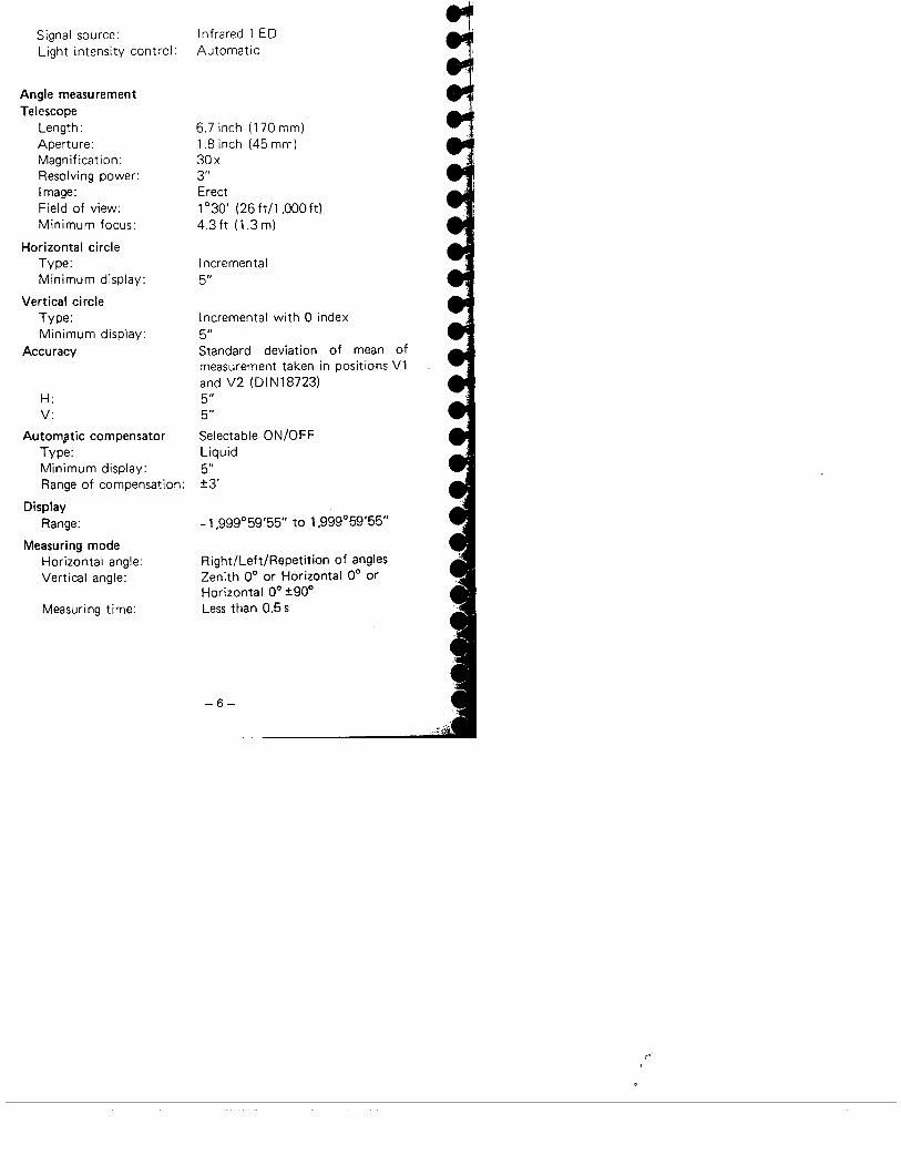
Signal source:Light intensity control:
Angle measurementTelescope
Length:Aperture:Magnification:Resolving power:Image:Field of view:
Minimum focus:
Horizontal circleType:Minimum display:
Vertical circleType:Minimum display:
Accuracy
H:V:
Autom,¡tic compensatorType:Minimum display:Range of compensation:
DisplayRange:
Measuring modeHorizontal angle:Vertical angle:
Measuring time:
Infrared LEDAutomatic
6.7 inch (170 mm)1.8 inch (45 mml30x3"Erect1 °30' (26 ft/l ,000 ft)
4.3ft (1.3m)
Incremental5"
Incremental with 0 index
5"Standard deviation of mean ofmeasurement taken in positions V1and V2 (DIN18723)
5"5"
Selectable ON/OFFLiquid5":!3'
-1,999°59'55" to 1,999°59'55"
Right/Left/Repetition of angles
Zenith 0° or Horizontal 0° or
Horizontal 0° :!90°
Less than 0.5 s
-6-
(.-
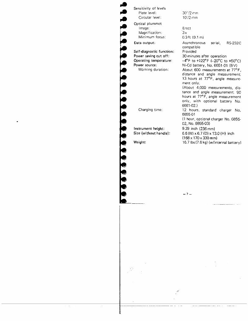
Sensitivity of levels
Plate level:Circular level:
Optical plummetImage:Magnification:Minimum focus:
Data output:
Self-diagnostic function:Power saving cut off:Operating temperature:Power source:
Working duration:
Charging time:
Instrument height:Size (without handle):
Weight:
30"'12 mm10'/2 mm
Erect3xa.3ft (0.1 m)
Asynchronous serial, RS-232CcompatibleProvided30 minutes after operation_4°F to +122°F (-20°C to +50°C)
Ni-Cd battery, No. 6651-01 (6V)About 600 measurements at 77° F ,distance and angle measurement;
13 hours at 77°F, angle measure-
ment only.(About 4,000 measurements, dis-tance and angle measurement; 90
hours at 77° F, angle measurementonly, with optional battery No.
6661-02.)12 hours, standard charger No.
6855-01(1 hour, optional charger No. 6855-02, No. 6855-03)9.29 inch (236 mm)6.6 (W) x 6.7 (D) x 13.0 (H) inch(168 x 170 x 330 mm)16.7 Ibs (7.6 kg) (w/internal battery)
-7-
;,,-

4. STANDARD EQUIPMENT
Fig. 4.1
SET4A main unit.... ... .
Internal battery,
No. 6651-01 .......... 2
Battery charger,
No. 6855-01 ..........
Battery charging adaptor,
No. 6660-00 .. . . . . . . . . 1Tubular compass, CP7
(accuracy::!l°) ....._.Lens cap ..............
Lens hood . . . . . . . . . . . . .
Vinyl cover . . . . . . . . . . .. 1Tool pouch ............ 1
Screwdriver . . . . . . . . . . .. 1Lens brush . . . . . . . . . . . .. 1Adjusting pin. . . . . . . . . . . 2Cleaning cloth ...... . . .. 1
Atmospheric correctionchart . . . . . . . . . . . . . . . .
Operator's manual. . . . . . .Field guide. . . . . . . . . . . . .Carrying case, SC46 . . . . . .
-11-
~.~~
..-,

,.,...,.t,.
~
5. LIETZ SYSTEM S3 STREAMLINED SURVEYINGSOLUTIONS
The compie:e. proven system for f:e!d measurement, data collee-:lon, data processing, vining and plotting.
Start an ail-day job and finish before noon?When you work with the Lietz System S3, you'll find yourselfdoing just that. This proven field-to-office connection doubles
your productivity and at the same time, actually improves your
accuracy.Using S3 components, you can be twice as competitive on everyjob. Twice as profitable.One sighting with a SET Total Station gives you simultaneousdistance and angle measurements. This data is then fed electro-nically into the SDR Electronic Field Book. Electronicallycapturing the data eliminates keying-in errors and the need forhandwritten notes. From here, data can be electronically trans-mitted into SDR MAP or SDR LINK surveying software on youri Blv-XTil-\T or 100% compatible computer.
System S3 Software includes the following programs:
SDRuNKIs an automated data communications program allowing for datato be transferred from the SDR Electronic Field Book to yourcomputer. SDR LI N K also has the ability to reduce field anglesand distances to a coordinate database. .A.SC Ii files can be gener-ated from the information that has been stored in the coordinatedatabase.
SDRMAPIs an automated plotting program which includes the SDRLlN Kprogram. SDRMAP uses the codes that were entered into theSDR Eiectronic Field Book to automatically generate a detailedplot of information. SDRMAP includes user-definable symbols,line types and code libraries. Plot files can be displayed on thecomputer screen, plotted on supported plotters, or may be sentto a CAD program using the DXF file creation.
-9-

SDRcONTOURIs an automated contour calculations module which generates
contours from the information transferred from the SDR Elec-
tronic Field Book. Definition of break lines, boundaries and
omitted areas may be selected from the SDR file or graphicallyat the computer using a mouse. All plotting is performed bySDRMAP.
SDRcALC*Is the COGO module that allows for defining coordinate infor-mation using coordinate geometry routines. Routines include:Traverse entry and adjustment, bearing/bearing intersection,bearing/distance intersection, curve calculations, establishment ofparal lei and perpendicular i ines, subdivide a i ine, and area calcu-lations. All plotting is performed by SDRMAP.
SDRROAO*IS a module of SDRMAP that performs the vertical geometrycomputations for road design. SDR ROAD supports a range ofmethods for specifying the profile of vertical geometry, includingthe application of super elevation. Up to seven profile lines canbe handled simultaneously.
SDRpROFILE.Plots profiles and cross sections of natural and design surface datasuch as road cuts and fills, stockpiles, etc. Allows cross sectiondata to be entered in the format of distance along the route
(stationrng), offset to the center line of the route, and height-either as reduced data or in level book format.
SDRvOLUME *Is a module of SDRMAP that has the ability to calculate volumesin three different ways. 1. compute end areas between two
surfaces at each cross section and multiply these by the distancebetween the sections. 2. compute volume between one or twoplanes and a surface from the areas of the triangles in the digitalterrain model, multiplied by their average height above the
planes. 3. Compute and plot the lines of no cut/fill after mergingtwo triangulated digital terrain models.
-10-
ro"

"
-~
,,~~~"~"'"'"lil---f
~
SDRDIGITZE*Is a module of SDRMAP that allows for a quick and easy meansof converting data in the form of plans and maps into data whichcan be computer processed for subdivision layout, contouring,area computation or road design.
* Contact your local Lietz Authorized dealer for availability andcost.
You and your Lietz System S3 can do it all with a minimumamount of training.
The Lietz nationwide organization of more than 50 SystemsCenters backs System S3 to give you all the training, service andsoftware support you need. The Lietz Warranty insures yoursatisfaction. Leasing plans are also available from your localAuthorized Distributor.
-11 -

THE LIETZ SYSTEM S3
2025 Modem
SDR
_..i
..
SET2SET3SET4
5DM3FRSDM3F
RED2ARED2LREDMINi2
DT2DT4DT5DT5A
Printers
l IBM-PC/XT/AT
and Lietz SDR Software
II.== ~ .~-""l i11 Plotters = Hewlett Packard
i Houston Instrument~.Fig. 5.1
;"-
-1? -
-....l-".!all" '..~~..~lili~~
~~~ll~~,
~~
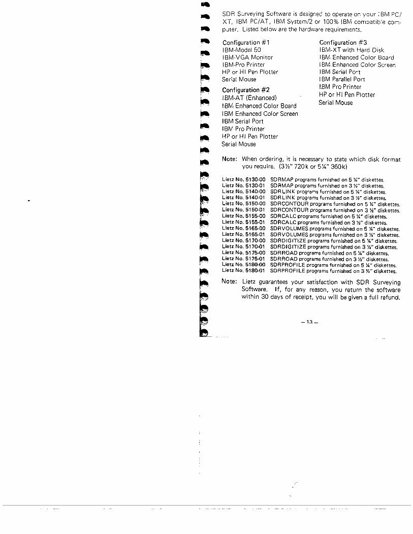
SDR Surveying Software is designed to operate on your IBM PC/XT, IBM PC/AT, IBM System/2 or 100% IBM compatible com-puter. Listed below are the hardware requirements,
Configuration # 1
IBM-Model 50
i BM-VGA Monitori 8M-Pro PrinterHP or HI Pen PlotterSerial Mouse
Configuration #2I BM-Ä T (E nhanced)I BM Enhanced Color BoardI BM Enhanced Color ScreenI BM Serial PortI BM Pro PrinterHP or HI Pen PlotterSerial Mouse
Configuration #3I BM-XT with Hard DiskI BM Enhanced Color BoardI BM Enhanced Color Screeni 8M Serial PortI BM Parallel PortI.BM Pro Printer
HP or H I Pen PlotterSerial Mouse
Note: When ordering, it is necessary to state which disk formatyou require. (3Yi" 720k or 5%" 360k)
Lietz No. 5130-00 SDRMAP programs furnished on 5 Yo" diskettes.Lietz No. 5130.01 SDRMAP programs furnished on 3)1" diskettes.Lietz No. 5140.00 SDRLlNK programs furnished on 5 Yo" diskettes.Lietz No. 5140-01 SDRLlNK programs furnished on 3)1" diskettes.Lietz No. 5150-00 SDRCONTOUR programs furnished on 5 Yo" diskettes.Lietz No. 5150-01 SDRCONTOUR programs furnished on 3 )1" diskettes.Lietz No. 5155-00 SDRCALC programs furnished on 5 Yo" diskettes.Lietz No. 5155-01 SDRCALC programs furnished on 3)1" diskettes.Lietz No. 5165-00 SDRVOLUMES programs furnished on 5 Yo" diskettes.Lietz No. 5165-01 SDRVOLUMES programs furnished on 3)1" diskettes.Lietz No. 5170-00 SDRDIGITIZE programs furnished on 5 Yo" diskettes.Lietz No. 5170.01 SDRDIGITIZE programs furnished on 3 )1" diskettes.Lietz No. 5175.00 SDR ROAD programs furnished on 5 Yo" diskettes.Lietz No. 5175-01 SDRROAD programs furnished on 3)1" diskettes.Lietz No. 5180-00 SDRPROFILE programs furnished on 5 Yo" diskettes.Lietz No. 5180-01 SDRPROFI LE programs furnished on 3)1" diskettes.
Note: Lietz guarantees your satisfaction with SDR SurveyingSoftware. If, for any reason, you return the software
within 30 days of receipt, you will be given a full refund.
-1:: _

:' ',- -~':": ;~,: ",:, ~ -, ::-.:.~ ;. ''.;,,' . "'",'.-',
Fig. 5.2
2028 MODEM
Universal Data system 202S LP Modern for use with SDR Elec-tronic Field Book.
Note: SDR E!ectronic Field Books must be used with 202Smodem to allow acoustic transmissions.
Lietz No. 5300-17
SDR ELECTRONIC FIELD BOOKS
The SDR collects and stores slope distance, zenith and horizontalangle data from the SET.Calculations can be performed on the data so that the measure-
ments can be verified in the field.ïhe stored data can be transmitted to a data processing system.
Lietz ~o. 5300-20 SDR20 Electronic Field Book with 32 Kmemory complete with Sokkisha cable (5303.041, female DB-25.adaptor (5300-09), operation manual (5300-08) and field case(5290-15),
Lietz No. 5300-22 SDR22 Electronic. Field Book with 64 Kmemory complete withSokkisha cable (5303-04), female DB-25adaPtor (5300-09), operation manual (5300-08) and field case(5290-15).
Lietz No. 5300.24 SDR24 Electronic Field Book with 128Kmemory. Data collection routines to support Wild, Top
con ,Pentax and Elta 46R instruments. (Includes same accessories asSDR22.1
-14-
rf
"

~MOUNTING BRACKET
Fits on L,etz No. 7512-52 Tripods and holds SOP ElectronicFie;d Books (or any hand-he:d ca:culatorl in such a way that itrotates with the instrument for convenient and easy operation.
Avai'ab:e in right hand or left hand configurations.
Lietz No. 5300-10Lietz No. 5300-11
(Right hand)(Left hand)
Fig. 5.3
-15 -

6. POWER SUPPLIES
The SET4A can be operated with the following combinations:
. Standard set.Optional accessories are notmarked with an asterisk.
'SET4A
Fig. 6.1
~-~. Internal
batteryNo. 6651.01
. Battery
chargi ngadaptorNo. 6660,00
~ . 12 hours chargerNo. 6855-01(120V ACI~ 1 hour quiCk
chargerNo. 6855'02(120VACI
~ AC power adaPtor6V . No. 6861-01
. l100 to 240V AC)
~ 1 hour cigarlighter chargerNo. 6855,03(12V DC)
Q - P External batteryCable 16V) (J No. 6661,02No. 6860.07
-16-
~15 hours charger
No. 6855,05(120V AC)
Cable to
cigar lighterNo. 6860-05
Cable to carbatteryNo. 6860-03
Use the SET4A only with the combinations shown here.
..,I..~
t'-
iQ~ 12V
tJExternal battery ~converterNo. 6860.02
Note: When using the SET4A with external power supplies, it isrecommended that for the most accurate angle measure-ments, the No. 6651-01 battery be left in place to balancethe weight on the axes.
,I..,.~¡.t
¡ar-I;
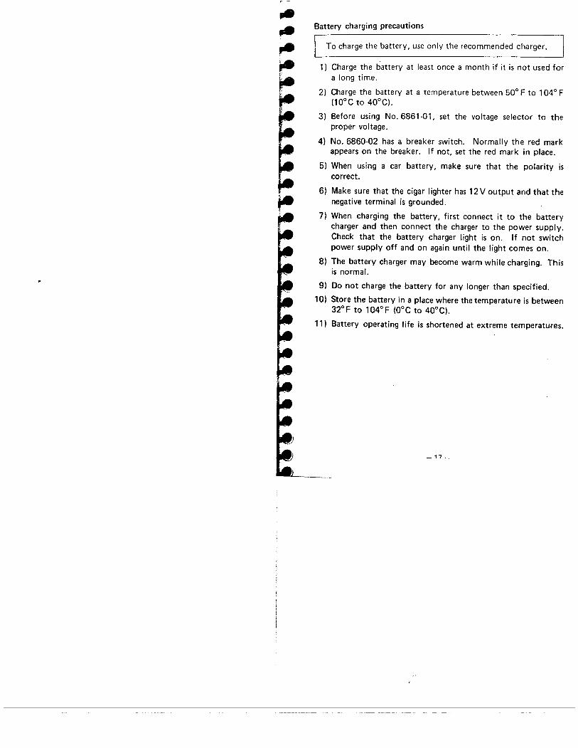
Battery charging precautions
To charge the battery, use only the recommended charger.
1) Charge the battery at least once a month if it is not used fora long time.
2) Charge the battery at a temperature between 50° F to 104° F
(10°C to 40°C).
3) Before using No. 6861-01, set the voltage selector to theproper voltage.
4) No. 6860-02 has a breaker switch. Normally the red mark
appears on the breaker. If not, set the red mark in place.
5) When using a car battery, make sure that the polarity iscorrect.
6) Make sure that the cigar lighter has 12 V output and that thenegative terminal is grounded.
7) When charging the battery, first connect it to the batterycharger and then connect the charger to the power supply.Check that the battery charger light is on. If not switchpower supply off and on again until the light comes on.
8) The battery charger may become warm while charging. Thisis normaL.
9) Do not charge the battery for any longer than specified.
10) Store the battery in a place where the temperatu re is between32°F to 104°F (O°C to 40°C).
11) Battery operating life is shortened at extreme temperatures.
_ 17_

7. DISPLAY SYMBOLS
HHorizontalangle right
~..~
H ... Horizontalangle left
~I Height difference
ii. N-coordinate
H ... Horiz.o.ntal anglerepetItion
Slope distance
Horizontal distance
H Horizontalangle hold
!: E-coordinate
_1_+ Compensated angle_1_ Tilt angle
Zenith angleH ..... 5.0 ~I!:+V 0'"
I '-i '-i '-i '-i '-i '-i '-i F- i Ci C, C' Ci C, C' C, CD. .
Distance, angle or error code
Fig. 7.1
-lR-
REM
Horizontal distancebetween two pointsFeetEDM power ON
:if.,.,
..~..~~~
~',..
. ,.,-:: ,
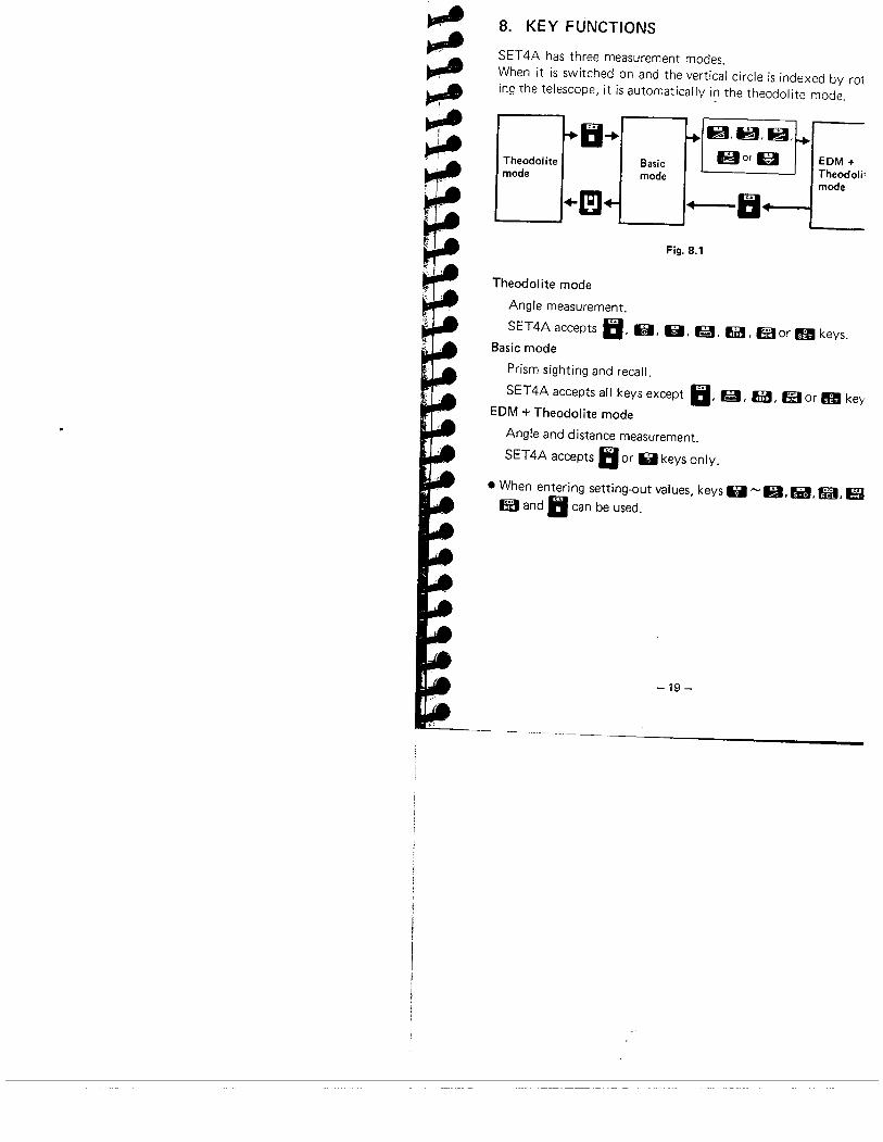
8. KEY FUNCTIONS
SET4A has three measurement modes.When it is switched on and the vertical circle is indexed by roting the telescope, it is automatically in the theodolite mode.
ii-+/IU;UlrTheodolite Basic Bora EDM +
mode mode Theodoli'.mode
+m ~ IIFig. 8.1
Theodolite mode
Angle measurement.
SET4A accepts II, la, 0, 11, fi, Mor g keys.
Basic mode
Prism sighting and recall.
SET4A accepts all keys except II, 11, fi, lXor g key
EDM + Theodolite mode
Angle and distance measurement.
SET4A accepts II or & keys only.
· When entering setting-out values, keys & ~R,Ii, 9, E'
IX and II can be used.
-19 -

ll B ÐIJ er ~~ El ~ m eïIIm ß rææIX
Fig. 8.2
m · Select theodolite mode.
II. · Stop data entry before m has been pressed.· Stop measurement and transfer to basic mode.
lI · Set horizontal angle to zero. To confirm zero setting,press ea.
. Enter "7".II . Measure slope distance.
. Enter "8".B . Measure horizontal distance.
. 'Enter "9".R . Measure height difference.
II · Change the sign of data before entry.. Recall data from memory.
II · Enter decimal point.. · Measure stake-out distance.
. Enter "4".B . Measure N- and E-coordinates.
. Enter "5".i! . Measure remote elevation.
-20-
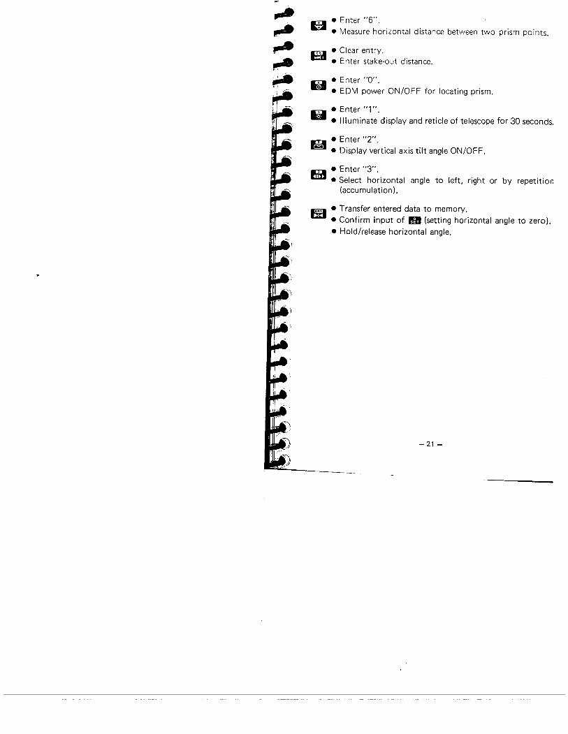
".",,.~...,
m · Enter "6".. Measure horizontal distance between two prism points.
E' . Clear entry.
. Enter stake-out distance.
. Enter "0".W . EDM power ON/OFF for locating prism.
. Enter "1"U . Illuminate' display and reticle of telescope for 30 seconds.
. Enter "2".
.~. . Display vertical axis tilt angle ON/OFF.
. Enter "3".6 . Select horizontal angle to left, right or by repetition
(accumulation).
m . Transfer entered data to memory.. Confirm input of 11 (setting horizontal angle to zero),. Hold/release horizontal angle.
-21 -

9. INTERNAL SWITCHES
Switches are located under internal switch cover O.
Switch
ON6 . OFF
5 ON.OFF
4 .ONOFF
ON3 . OFF
SET 4
co
z IIO~
C'
N~
Fig. 9.1
Function
Manually index vertical circle by VL. V2Automatically index vertical circle .by transittingtelescope
Vertical circle compensator offVertical circle compensator on
Display distance in feetDisplay distance in meters
Distance corrected for earth-curvature and refractionDistance not corrected for earth-curvature and
refraction
ON Display vertical angle with 00 horizontal :!90°. OFF Vertical angle display controlled by switch 1
ON Display vertical angle with 0° horizontal on face VL. OFF Display zenith angle
(The asterisk indicates the position of each switch at the time of shipping.)
2
. Before changing switch settings, turn power switch OFF.
-22-
~I.,...;

,.".~pA.."',.
10. OPERATION
10.1 PREPARATION FOR ANGLE MEASUREMENT
10.1.1 Battery, No. 6651-01: Mounting and check
1) Confirm that the power switch ~ is OF F.2) Mount the battery No. 6651-01 in the SET4A.
Hold the left standard when inserting the battery. Push ituntil a click is heard to indicate correct location. Confirmthat the battery is fi xed securely.
Guide
Releasebutton
(To remove the battery, turn the power switch OFF and)push down the release button of the battery.3) Two short audio signals are heard when the power is switched
ON. The display shown in CD and then CI indicate the instru-ment is in normal condition.

If the battery voltage is too low, the display will appear as
shown below. Set the power switch OFF and replace thebattery with a charged one, or charge the battery.
b. d f eiBattery voltageis too low.
b. eifel
Fig. 10.3
10.1.2 Compensation of zenith angle1) Remove the switch cover O.2) To use zenith angle with compensation, set switch 5 to OFF
with a screw driver. (The factory setting is OFF.)3) Replace the cover.
SET 4
Compensation select switch
ON - Without compensation
OFF - With compensation
v_1_+
90-00'00"
The _,_+ mark appears when theinternal switch 5 is set to 0 F F.When" this mark appears. the angleis compensated automatically.
H ..nenn'nn"Ul.'l.'UU
Fig. 10.4
The internal tilt sensor has a range of :!3' and a resolution of5". Read the automatically compensated zenith angle when
the display is steady. When the display is not steady due tovibration or strong wind, set switch 5 to ON to use theSET4A without compensation.
_74_

,.......,.;.
10.1.3 Centering the SET4A by adjusting tripod leg length1) Make sure that:
a. The tripod head is approximately leveL.
b. The tripod shoes are firmly fixed in the ground.2) Set the SET 4A on the tripod head.. Tighten the centering
screw.3) Focus on the surveying point:
a. Turn the optical plummet eyepiece ~ to focus on thereticle.
b. Turn the optical plummet focusing ring ID to focus on thesurveying point.
4) Turn the leveling foot screws -Ð to center the surveying pointin the reticle.
5) Observe the off-center direction of the bubble in the circularlevel æ. Shorten the leg nearest that direction, or extend theleg farthest from that direction.Generally, two legs must be adjusted to center the bubble.
6) When centering of the circular level is completed, turn theleveling screws to center the plate level W bubble.
7) Look through the optical plummet again. If the surveyingpoint is off-center, loosen the centering screw to center thesurveying point on the reticle. Tighten the centering screw.
8) Repeat 6), 7) if the plate level bubble is off-center.
10.1.4 Focusing
1) Looking through the telescope, turn the eyepiece fully clock-wise, then anticlockwise until just before the reticle image
becomes blurred. i n this way, frequent refocusing can bedispensed with, since your eye is focused at infinity.
2) Loosen the vertical ~ and horizontal clamp fI.Bring the target into the field of view with the peep sight ~.Tighten both clamps.
3) Turn the focusing ring (I and focus on the target.Sight the target with the vertical ~ and horizontal finemotion screws ti. Focus on the target until there is noparallax between the target and the reticle.
-25 -

Parallax:Relative displacement of target image in respect to thereticle when observer's head is moved slightly before theeyepiece.If sighting is carried out before parallax is eliminated,
this will introduce errors in reading and will impair your
observations.
10.2 ANGLE MEASUREMENT
Make sure that:a. The SET4A is set up correctly over the surveying point.b. Battery voltage is adequate.
10.2.1 Automatically indexing vertical circle1) Turn the power switch f1 ON.
Make sure that the display appears as shown below.
I v
_1_+nu
H ..n-nn'nn"uuuuu
Fig. 10.5
2) Loosen the vertical clamp ~,and use the telescope plunging
knob ~ to rotate the telescope completely.(Indexing occurs when the objective lens crosses the horizontalplane in position V1,)
When the vertical circle is indexed, an audio signal is given andthe display appears as below.
v_1_+
gn-nn'nn"uuuuu
H ..n-nn'nn"uuuuu
Fig. 10.6
-26~

~".~pIr-~,'r,.~l-~..~,.
Angle measurement can now begin.Note: When the power switch is turned off for any reason.
the vertical index is lost. When the power switch isturned back on, the vertical index must be redeter
mined.
10.2.2 Angle measurement
Before this procedure, index the vertical circle.
1) Select the horizontal angle right or left with æ according tcmeasuring method.
Display
H I~ ........ Horizontal angle right
H ~I ............ Horizontal angle leftl
H i ~ ~ ..... Horizontal angle repetition
Fig. 10.7
When æ is pressed, the display changes alternately as shownin Fig. 10.7.
2) Sight the first target A.3) Press. then IX to set the horizontal angle display to 0°.
v_1_+
8S.Y2' ia"
H .. . , "nnnnnuuuuu
Fig. 10.8
-27 -

4) Use the horizontal clamp ~ and the vertical clamp W to sightthe second target B.
Zen ith angle y
88'03' :5"
Horizontalangle
H ..
60.,-0'35"
Fig. 10.9
The displayed horizontal angle is the angle between targets Aand B.
10.2.3 Setting the horizontal circle to a required valueTo set the horizontal circle to the reference target, for example
90° 1 0'20":
1) Loosen the horizontal clamp fJ and the lower clamp 0 andhold the upper alidade lightly. Turn the circle positioningring æ until the display becomes about 90° and tighten both
clamps. Turn the horizontal fine motion screw ~ until thedesired angle is displayed.Note: When using the lower clamp 0, push in the cover 8.
2) Press m.
H I...... Horizontal anglehold display
Fig. 10.10
y_1_+
B -¡ :2'''ff
H .
9fi :0'20"
Fig. 10.11
-28 -
.,..-1
(0'
,.....~l~
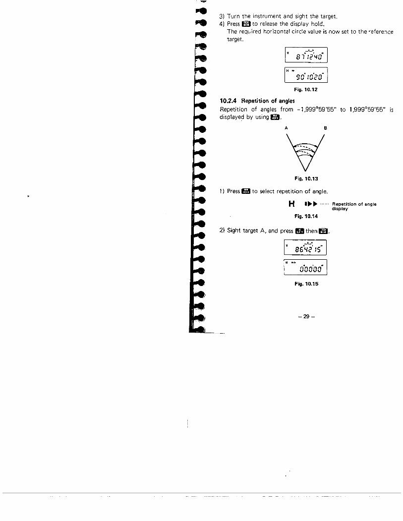
3) Turn the instrument and sight the target.4) Press EI to release the display hold.
The required horizontal circle value is now set to the referenceta rget.
_1_+
8 i :2'''0"
H ..
90- :0'20"
Fig. 10.12
10.2.4 Repetition of angles
Repetition of angles from -1,999°59'55" to 1,999°59'55" isdisplayed by using æ.
A 8
~-~
---"'-..
Fig. 10.13
1) Press fi to select repetition of angle.
H I~~ ...... Repetition of angledisplay
Fig. 10.14
2) Sight target A, and press IH then m.
.._+
86+,,2' :5"
H ...nenn'nn"uuuuu
Fig. 10.15
-29 -

3) Use the horizontal clamp ~ and the horizontal fine motionscrew ~ to sight target B.
IV 85.-;'9+'55"1
H ...
:85.30'20"
Fig. 10.16
4) Press W to hold the horizontal angle display.5) Use the lower clamp 0 and the horizontal fine motion screw
~ to turn back to target A.
vi +
B6.~2' :5"
H ,
:85.30'20"
Fig. 10.17
6) Press W to release the display hold.7) Use the horizontal clamp and the horizontal fine motion screw
to sight target B.
v_1_+
85. :S'SS"
Double angleH ...
31 :OO''-O"
Fig. 10.18
8) Repeat 4) to 7) steps to measure repetition of angles.9) To release the repetition of angle display, pressli.
-30-
.,:i
(,.

..li,.I!~..t
l+~~l-....,.~
10.3 PREPARATION FOR DISTANCE MEASUREMENT
10.3.1 Prism constant correction
1) Remove the prism constant switch cover (¡ with a coin.2) Use the screwdriver to turn the prism constant setter to match
the reflecting prism constant correction value.
i.e. For a prism constant correction value of -3 cm, set the
index to 3 (-3cm).
~i3P'"e9 '"
Prism constantsetter
..11
Fig. 10.19
3) Replace the cover.
Prism constant values of Sokkisha reflecting prisms.
The prism constant of the AP series prisms is 30 mm (the samevalue as the previous Sokkisha prism) using the prism spacer
AP01 S (standard accessory). The constant can be changed to40 mm by removing the prism spacer.
Old prism PR03 AP01 S + AP01 New prism AP01
(( ~-~ .30mm 30mm 40mm
Prism constant value
Fig. 10.20
When using reflecting prisms with constant values other thanthe above, a prism constant correction of 0 cm to -9 cm canbe set in steps of 1 cm using the prism constant setter.
-31 -
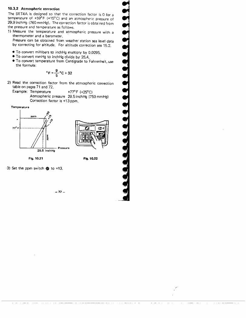
10.3.2 Atmospheric correctionThe SET4A is designed so that the correction factor is 0 for atemperature of +59°F (+15°C) and an atmospheric pressure of29.9 inchHg (760 mmHg). The correction factor is obtained fromthe pressure and temperature as follows.1) Measure the temperature and atmospheric pressure with a
thermometer and a barometer.Pressure can be obtained from weather station sea level databy correcting for altitude. For altitude correction see 15.2.
. To convert millibars to inchHg multiply by 0.0295.
· To convert mmHg to inchHg divide by 25.4.. To convert temperature from Centigrade to Fahrenheit. use
the formula:
OF =~oC + 325
2) Read the correction factor from the atmospheric correction
table on pages 71 and 72.Example: Temperature +77°F (+25°C)
Atmospheric pressure 29.5 inchHg (750 mmHg)Correction factor is +13 ppm.
Temperature
77° F
Pressure29.5 inchHg
Fig. 10.21 Fig. 10.22
3) Set the ppm switch ~ to +13.
-::? _

......ei..OJ....
~,',',',.rlA,.r-~~
4) To obtain the atmospheric correction factor by computationa. inchHg - of system (English):
Atmospheric correction factor
10.5 x PX = 278.96 - 1 + 0.002175 x t
P: Atmospheric pressure in inchHgt: Temperature in Fahrenheit
Example: P = 29 inchHg, t = +60°F
10.5 x 29ppm=278.96- 1 +0.002175x60 =9.61 =; 10
Set the ppm switch to +10.
b. mmHg - °c system (Metric):Atmospheric correction factor
0.3872 x PX = 278.96 - 1 + 0.003661 x t
P: Atmospheric pressure in mmHgt: Temperature in Centigrade
5) For slope distances equal to or more than 6,561.68 ft(2,000.000 m) (exceeding the maximum display 6,561.67 ft(1,999.999 mIL. the ppm switch should be set to 0 and the
corrected slope distance calculated by the formula:
D = (6,561.68 + d) x (1 + X )1,000,000
D: Corrected slope distanced: The display of slope distance when ppm is set to 0X: Correction factor in ppm
Example: Slope distance 6,594.48 ft (displayed as 32.80 ft)X = +5ppm
D = (6,561.68 + 32.801 x (1 + 5 )1,000,000
= 6,594.51 ft
-11_

10.3.3 Earth-curvature and refraction correction
1) Remove the internal switch cover O.2) To correct horizontal distance and height difference for earth-
curvature and refraction, set switch 3 to ON with a screw-
driver.3) Replace the cover.
SET 4
Earth-curvature and refractioncorrection switch
~mo ON - Correction is applied.
~OI OF F - Correction is not applied.
Fig. 10.23
· This correction is performed in the measurement of hori-
zontal distance and height difference.The value displayed by the SET4A is computed by thefollowing formula:
When the switch is ON~ Horizontal distance after correction
KH' = S x sin Z - 1 - 2" X S2 x sin Z x cos Z
RHeight difference after correction
V' = S x cos Z + ~ x S2 x sin2 Z2R
When the switch is OFFHorizontal distance H = S x sin Z
Height difference V = S x cos ZS: Slope distance (value after atmospheric correction)Z: Zenith angle
K: Atmospheric refraction constant (0.142)R: Radius of the earth (2.09 x 107ft)
_~4_
..I..I!
-iMif.,I
,-'

..
.-..ll~l-..Iel-....l-l-
Target
S~VSurveying point
H
H'
Average sea level
Fig. 10.24
Example: Amount of correction for a zenith angle of 70°
S (ft) 500 1,500 3,000 5,000H' - H (ft) -0.00 -0.03 -0.13 -0.36V' - V (ft) 0.00 0.04 0.16 0.45
Note that the horizontal distance is a distance measured at
the height of the surveying point above the sea leveL. If
necessary, r8duce this distance to the average sea level and
apply the local projection correction.Further, since the SET4A does not apply the earth-curvatureand refraction and atmospheric corrections when a slopedistance is more than 6,561.67 ft, such corrections shouldbe performed by computation.
10.3.4 Prism sighting
1) Sight the center of the reflecting prism with the telescope.2) Set the return signal audio switch 6) to Jl .3) Set the power switch ~ to ON and press ia.
Iaturns the power supplied to the EDM unit ON or OFF.Usually the power of the EDM unit turns OFF automaticallyafter 1 second of inactivity and the power source mark dis-appears.But when ia is pressed, power is supplied to the EDM unitfor about 2 minutes to permit prism sighting.a. When power is supplied to the distance measurement unit
(EDM unit), the power source mark CD is displayed.
-35-

b. When the reflected light is received by the telescope, anaudio signal is heard and the return signal lamp ~ lightsup.
When the light intensity coming back from the prism isvery high, the return signal lamp may light up, even fora slight mis-sighting. Make sure that the target center issighted correctly.
4) Switch off the audio target acquisition.
10.3.5 Mode selection1) Select the mode switch ~
or TRACK. for tracking.to MEAS. for fine measurement,
lD
~ MEAS.: finemeasurement
TRACK.: trackingmeasurement
6'
Fig. 10.25
MEAS.: Measures in hundredths of a foot, first after 6 to 8seconds, then every 4 seconds.
TRACK.: Measures in tenths of a foot, first after 6 to 8
seconds, then every 0.4 to 1 second.
- 36-
(~-
..
..
.,1!i;i,.".Iel-'....lIli,.
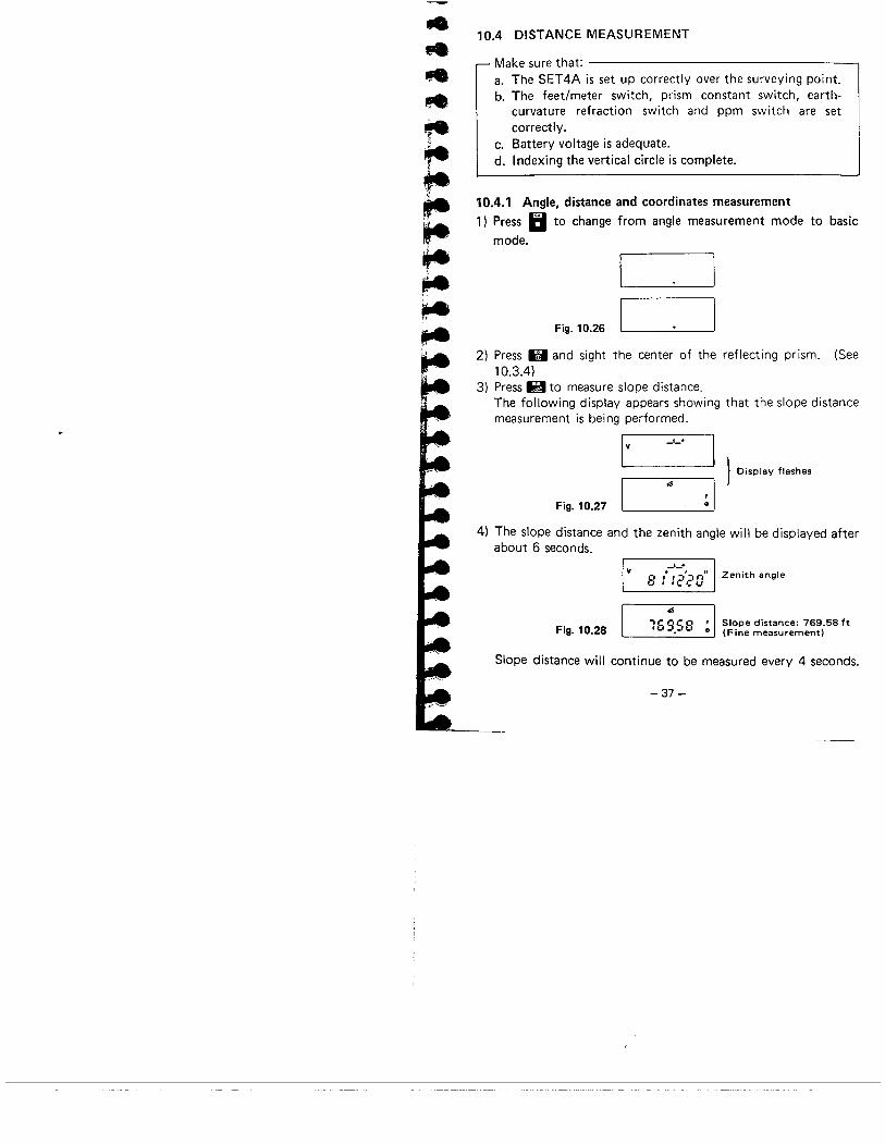
10.4 DISTANCE MEASUREMENT
Make sure that:a. The SET4A is set up correctly over the surveying point.b. The feet/meter switch, prism constant switch, earth-
curvature refraction switch and ppm switch are setcorrectly.
c. Battery voltage is adequate.
d. Indexing the vertical circle is complete.
10.4.1 Angle, distance and coordinates measurement1) Press II to change from angle measurement mode to basic
mode.
Fig. 10.26
2) Press. and sight the center of the reflecting prism. (See10.3.4)
3) Press I1 to measure slope distance.
The following display appears showing that the slope distancemeasurement is being performed.
I y
_1_+
I
L 0 isp lay flashes
I
a;
~ IFig. 10.27
4) The slope distance and the zenith angle will be displayed afterabout 6 seconds.
y_1_+
o l.i~-l=ln" Zenithangleo , ie C..
Fig. 10.28 16;58 ,i Sl~pedistance: 769.58ft. .. (Fine measurement)
Slope distance will continue to be measured every 4 seconds.
-37 -

· Maximum display for slope distance is 6,561.67 ft(1,999.999 m). For longer slope distances, see 10.3.2.
· When the following keys are pressed instead of H in step3), the measurement corresponding to each key is per-formed.
Key During Measuredoperation measurement value
I H
..
I
H .. Horizontal'-15°38''-0
..angle
IB
I
~
ø I
~ HorizontallS0.53 , distance
ø
I v
_1_+
I
-'-+,. . :/=- n
.. Zen ith angle8 . '.. '- '-,II
i ø I
Height11.66 , difference
ø
IS3 ie Cr , N-coordinate
'.u-,~ø I
'" '"
5'-:3.19 , E-coordinateø
Fig. 10.29
5) Press II to stop measurement.
Note: The SET4A computes the coordinates using thefollowing formulas:
ii. N-coordinate = H cos 8H
!: E-coordinate = H sin (JH
00
Fig. 10.30 Surveying point (0.0)
-38 -
(C-

l-..l-l-~
,..",te"l
6) After stopping, you can recall the following observational data.which are stored in the instrument, by pressing the appro-
priate keys.
_1_+
8 t :2'20.
Zenith angle
ii
i/ I"
-i
159.58 , Slope distance
.. l-S038'l-0.1Horizontalangle
~HI
.. Horizontal1 S D.S :: , distance
Key operation
rn H
Measured value
_1_.o ,. .-.',n"\. . ie c...
Zenith angle
1-II1-
R
l-S038'l-0.Horizontalangle
HFig. 10.31 I
vI °
8 :ï-2'20.Zenith angle
:l.SSHeightdifference
S3 :.69 ' N-coordinate
'"
Sl-3.19, I E,coord inate
. Each measured value displayed is the result obtained in thelatest measurement.
7) To use as a theodolite after distance measurement, press ~.
-39 -

1004.2 Stake-out measurement1) Stake-out data is a given distance where a stake is supposed to
be driven into the ground.The SET4A displays the measured distance minus the givendistance (sta ke-out data).
Displayed value = Measured value - Stake-out data
2) Entry of stake-out data
The stake-out data need to be entered once for the slope
distance, horizontal distance, height difference or remoteelevation measurement.The SET4A should be in the basic mode for data entry.
e - I Enter data 1- IX
· To clear the entry halfway, press E'.
· To stop the entry halfway, press II.
· The range of stake-out data is between -9,999.99 ft(-9,999.999 m) and 9,999.99 ft (9,999.999 m).
· The data once entered is stored until the power switch isturned OFF, then becomes O.
3) Confirmation of stake-out data
e-~
Confirm the displayeddata -B
· To correct the stored data, re-enter it.4) Measurement
The following measurements can be performed with H.
.Key operation
Iii i I ~ B Slope distance stake-out. H Horizontal distance stake-out
I ~ R Height difference stake-out
Fig. 10.32
Example: Horizontal distance stake-out measurement whenstake-out data is 90.5 feet.
-4n-
;,'

..
..
..~iP.Ie,íe¡.
=je,.IeIe
a. Entry of stake-out data
IEi i i-HIi5!~m ~Enter the data
'-0
90.SO F
',0.,,'1'".,'-'.'_"_' l.'
Stored data isdisplayed
About IO.5s
b. Measurement
liiUlI1'
I
5'0 ~
Fig. 10.33
I
· i
1-,'-.'. :'::5"0:' i: -, ii
,-0", I ..: 2 '- ~ Measurement. stop
Measured distanceand horizontal angle
Duringmeasurement
Fig. 10.34
The measured horizontal distance is 1.24 feet longer than thestake-out data (90.5 feet).
-41 -
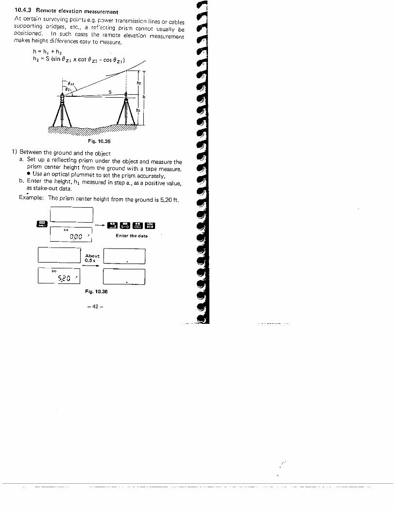
10.4.3 Remote elevation measurement
At certain surveying points e.g. power transmission lines or cablessupporting bridges, etc., a reflecting prism cannot usually bepositioned. i n such cases the remote elevation measurement
makes height differences easy to measure.
h=h¡+hihi = S (sin 8Z1 x cot 8zi - cos 8Z1)
s
Fig. 10.35
1) Between the ground and the objecta. Set up a reflecting prism under the object and measure the
prism center height from the ground with a tape measure.
· Use an optical plummet to set the prism accurately.b. Enter the height, h 1 measured in step a., as a positive value,
as stake-out data.
Ex~mple: The prism center height from the ground is 5.20 ft.
El
I '-ió lillil ms.o
,-,,-,.e¡ F1_'.t.I'-' Enter the data
About0.5s
s-o
c :11; F_'!~ '_I
Fig. 10.36
-42-
"f'
i
11
¡.'
....,.,..-we..l-.....ÎA..,r-
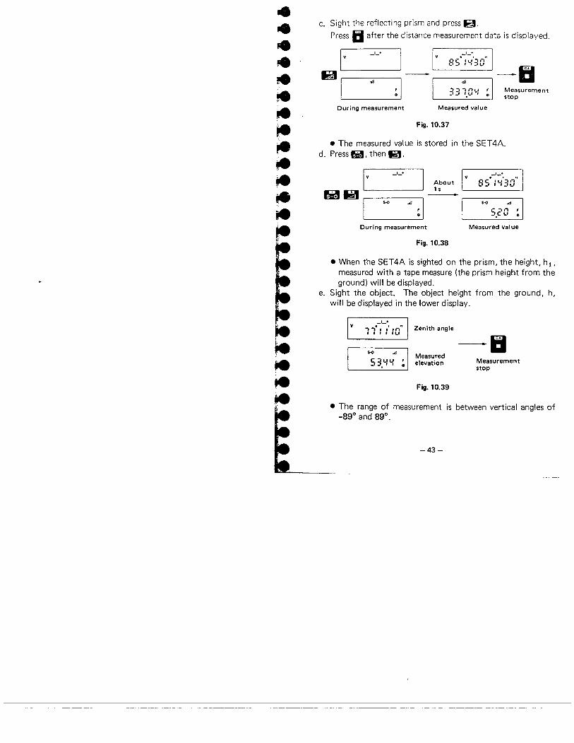
c. Sight the reflecting prism and press i!.
Press Ii after the distance measurement data is displayed.
I V
_1_+
I
_1_.. . "8S :t.:::G
..1,.
~ I
,. -II:i=- "'"l.' , Measurement_, _, '.'-' I ~ stop
During measurement Measured value
Fig. 10.37
. The measured value is stored in the SET4A.d. Press y, then 1l.
ri e I._1_+
IAbout15
I
$-0
., ~ I
_1_+
SS'I'-:'30"
5-0 ..5.20 ~
During measurement Measured val ue
Fig. 10.38
. When the SET4A is sighted on the prism, the height, hi,measured with a tape measure (the prism height from theground) will be displayed.
e. Sight the object. The object height from the ground, h,
will be displayed in the lower display.
_1_+
"I "I" " i n" Zenith angle, fl. ...' -IIsS3.YY" ~ IMeasuredelevation Measurement
stop
Fig. 10.39
. The range of measurement is between vertical angles of-890 and 890.
-43-
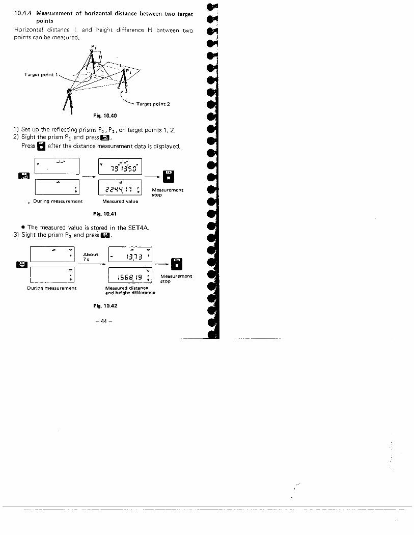
10.4.4 Measurement of horizontal distance between two targetpoints
Horizontal distance L and height difference H between twopoints can be measured.
Target point 1
~ Target point 2
Fig. 10.40
1) Set up the reflecting prisms Pi, P2, on target points 1,2.2) Sight the prism PI and press ø.
Press Ii after the distance measurement data is displayed.
I V
_1_+
I
_1_+V
1~¡ : ,'SOH
IB -III
.:
~ I
.:
22'-:'-. ,-. , Measurementi. ..stop
~ During measurement Measured value
Fig. 10.41
. The measured value is stored in the SET4A.3) Sight the prism P2 and press 6.
61~ I
:1
:1
I-
I
About7 s :3.13 :1_11
: I Measurement.. stop:568. :9
During measurement Measured distanceand height difference
Fig. 10.42
-44-
..".."~..
.il

..lll.~
I
11. SELF DIAGNOSIS
If there is any fault in the measuring function, the error codes
shown in the following table will be displayed.
Display Meaning Action
'- 'e _, Battery vo i tage is too Replace the battery'_I Ci 1_ i.' low. with a charged one, or.
charge the battery.
,- I '-i " * Error when measur- Reset the horizontale i i.1 '_iing horizontal angle to 0° (0 gon),aangle.
C i '-i , * Error when measur- Index the vertical'- , '-' ,ing a zenith angle. circle again.
C , , ,- Compensator range Level the SET4Ai. , , :'Tilt angle ex- again.error.
ceeds -3'.
,- , , -, Compensator rangee , , ,Tilt angle ex-error.
ceeds +3'.
C -, ,-, ,-, Incoming reflected Sight the ref lect i ng i'- e ,_, i.' i
light decreased during prism again.measurement. Incom- Increase the numbering reflection was dis- of reflect ing prismsturbed. for long distances.
Measure the distancee ,-,,- e Incoming reflection is again confirming the-' i."- , i. totally absent when condition with the,- -,,-, , the instrument is return signal lamp ore e ,_, ,ready for distance sound.measuring.
-45 -

Display Meaning Action
C :,,-,C Error when measuring Sight the reflecting'- '- '-"-' the initial slope dis- prism to perform
tance during either slope distance meas-remote elevation or urement again.horizontal distancebetween two pointsmeasurement.
i: -,,-, -, During remote eleva- Press Ii to stop meas-'- e '-' , tion measurement, thevertical angle is more
uring.
than :!89° or themeasured distance is
more than:!9,999.999 m.
,- -, ,-,,-, The measured dis- Press Ii to stop meas-i: e ,_, Ci tance is thanmoreuring.
:! 19,999.99 ft(:! 19,999.999 m).
* If the SET4A is rotated faster than four revolutions per second,the error indication "El00" or "El01" is displayed.
~
When the error indication "E" appears with any number otherthan the ones above, please contact our agent.
_ii~ -
. '--":. ..__._------..~-
r'",
..
..4'..'..........-.l-
;.l-
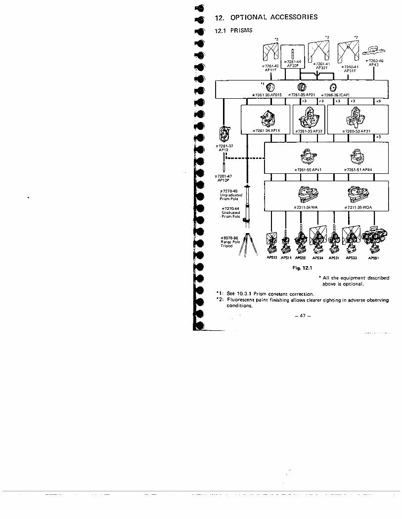
12.1 PRISMS
12. OPTIONAL ACCESSORIES
,#7261,37
AP12
1:---.--~
#7261,47AP12P
#7270-48 !UngraduatedPrism Pole
# 72 70-44GraduatedPrism Pole
#8078'961lRange PoleTripod
l,:. .~~"
'2 '2 '2~~. ~, "7260-46"7261.41 AP43AP32T "7260.41
AP31T
~ ~
.#7261,34 AP11
x3
~ ê#7261,50 AP41 #7261.51 AP44
~ ~"7311.34WA #7311,35WOA
APS12 APS11 APS APS APS3l APS APS1
Fig. 12.1
* All the equipment describedabove is oPtionaL.
*1: See 10.3.1 Prism constant correction.*2: Fluorescent paint finishing allows clearer sighting in adverse observing
conditions.
-47 -

Precautions
i; CareLJllY face ;re reflecting prism to'i.:årcs the i¡:strument;sight the target center accurately.
2) To; Jse the tripie prism assembly .A.P31 or ,A.P32 as a single
prism (e.g. for s:-or: distances!. mount the single prism APC1in the center hoie of the triple prism holder.
3) Check that "236" (the height of the SEi4A) is displayed inthe windov.j of the instrument height adapto;r .A.P4 i.ihe height of the AP41 can be adjusted as follows:CD Loosen the two fixing screws.(ì Turn the center part counterclockwise to unlock it.CI Move it up or down until "236" appears in the window.
G) Turn the center part clockwise to re-Iock it.\I iighten the fixing screws.
-I" r;':~~)~ \b;
,- l(J;'.l)~U.5.))
lElEm iIfImJ(Emr
::J1";:...\~.i
"WOw'-CD
((5))
Fig. 12.2 Fig. 12.3
4) Use the plate level on the AP41 to adjust the tribrach circularlevel as in 13.1.2.
5) Check the optiæl plummet of the AP41 as in 13.1.6.After ali checks and adjustments have been completed, makesure that the AP41 optical plummet sights ,he same point asthe optical plummet of the SET4A.
- 48-
~-1.,.,

;.:..;..l.:...
i~;~'~H!
=~....í';
12.2 TRIBRACHS ANDADAPTORS
OPTICAL PLUMMET TRIBRACHFor precision plumb'ng. Has circu.lar 1evei vì()1 with sens::¡\;ity cf 10
minutes per 2 mm.Optical plummet focus bv push-pullslide. Range: 1.5 t050 ft.No. 7311-35
Fig. 12.4
TRIBRACH LEVEliNG BASESame as above but without opticalplummet.For use with Azimuth Base(7150-41 ¡.No. 7311,3L
Fig. 12.5
TRIBRACH ADAPTORAdapts Irer' 5/8 x l' :hread ~,
L¡e~z or O~:ìe~ bra;i(j tribroch.
A!lovvs i~s:aliat¡on of Lietz priSTor other 5/8 x 11 fema!e.thrt-~ad ac
cesscries in:o t;-ibròch.No. 7311,37
Fig. 12.6
TRIBRACH ADAPTORSimilar to above except with removable, rotatable center.No. 7311,38
fl."~:,id~'.~1ê' ;~.,-
Fig. 12.7
TRIBRACH ADAPTORAccePts prisms with 211.8 mm bay-onet-type base.
No. 7311-40
OPTICAL PLUMMET TRIBRACHADAPTORSimilar to above but with rotating'vertiça! axis 2nd optical piummetfOr precise positioning of prisms in'tribrachsv'dhout optical plummet.No, 7311-111

12.3 TARGETS
TRAVERSE SET
WITH C.:;PRYING C,,5::.. Forprecise triangulaiion sU"v'e'~'sl day or
ni;;I't,Na. ï312-45 Set conra;ns t\.':o eôchof the fcdowíng:
7311-35 Optical Plumme: T,-¡brachs7311,37 Tr:YfJch adaptors7312-39 II'umination ur:its7312-40 Rotatable sighting targets
rY()U nted on a base
~-~:.:::~.,
-~_ht~
Expiodedview
.Fig. 12.8
LARGE TARGETLarge target 8 y." x 1 i J," attachesto regular target (No. 7312~40j to
provide increased sighting range.No. 7312,42
12.4 POLES
RANGE PLUMBING POLE
Aurrim!rn tub'ng and brass fiTtingswith hardt~n"d steel point. Height
adjusts frorn 5~" to 100", Uppersection mauntir-;; stud accepts singieor tripie relrO prisms; lock il1g disc
.prevents prism rota I ion, Includesreplaceable rod lavel (No. 8071-90).No. 7270-48
-= =t. _,Fig. 12.9
HEAVY-DUTY GRADUATEDTELESCOPING PRISM POLE. Alumil1urn tubing with brass fit-
tings; outside diameter 1," inches! . Positive coHet-type lock ing syS'
H"m. ;..13Ie 5;8 x 11 prism mouming
stud. Lock ing d;sc secures prism
. Repiaceabie pC'nt (8078,50j
. Adjustable heighTs-54 to 100inches
. Engraved graduations on extend-
ing member icr measuri rig prismheight (feet. tenths and metric)
No, 7270-44
Lr'¡
tj
~:1
!~I
Fig. 12.10
~
~

TRIPODS
Tripods recDrnniended for use \"¡ii:hthese accessories (not ¡"eluded inprice) :
No. 7512-52 Wide Frame.
Extension Leg (wood)
No. 7536-75 Wide Frame.
Extension Leg (aluminum)
PRISM POLE TRIPOD. Easy-to.use. ful!y adjustable tri-pod for Lietz Nos. 7270-48 and
7270-44 Prism Poles. Allows fast leveling while remain,
ing centered on point. Spring-action ieg clamps work
with one hand for rapid setup. Lets you take foresights or back-
sights to a reliable, steady re-
fere nee
No. 8078,96
Fig. 12.11
7l'1 ,.,
1,1 ,_, \.. ~- ~.::
RANGE POLE TRIPODHeavy-duty. Made with meta:center castings. Rustproof steel iegs,adjustable for uneven ground.No. 8078-95
\.\\\\\\\\\.
::"'o-~\;\
y
Fig. 12.12
,.
12.5 THERMOMETER ANDAL T1METER
POCKET THERMOMETERRefillable rnetal case. Merc;r,fjlied. R?nq'~~: -3D':' to 120'~F in2:increrntY11s.No. 8006,12
~ýC..~-"" Fig. 12.13
BAROMETER/AL TIMETERwirJi watch,type case.Engi¡sli.RÐnge 0 to 15.000 ft.No. 8001,70
Fig, 12.14
12.6 DIAGONAL EYEPIECE#7311-18
Tiie dlagona: eyepiece is convenientfor. steep observations and in placeswhere space around the instruinen,is lirnited.Remove the eyepiece lI by loosen,ing the mounting ring, and screw irithe diagonal eyepiece,
Setting up the 7311-18
-S'_
Fig. 12.15
-51 -
13. CHECKS AND ADJUSTMENTS
It is i-:::o;-tant hat t:-15 SET4A is periodically checkec and adjust-ed. In ajdit:on, the irs::ulTent shouid be c'ie::~ed a~ter trans,
,;:ortaticn. long storage e' ,;,,hen damage to t:-ie instrument iss~ispected to have occurred, The checks should be performed asfollows'
13.1 ANGLE MEASURING FUNCTION
13.1.1 Plate level13.1.2 Circular level13.1.3 I ndex error of the ti It angle sensor13.1.4 Reticle adjustments
a) Perpendicularity of the reticle to the horizontal axisb) Vertical and horizontal reticle line positions
13.1.5 Coincidence of the distance measuring axis with the
reticle13.1.6 Optical plummet
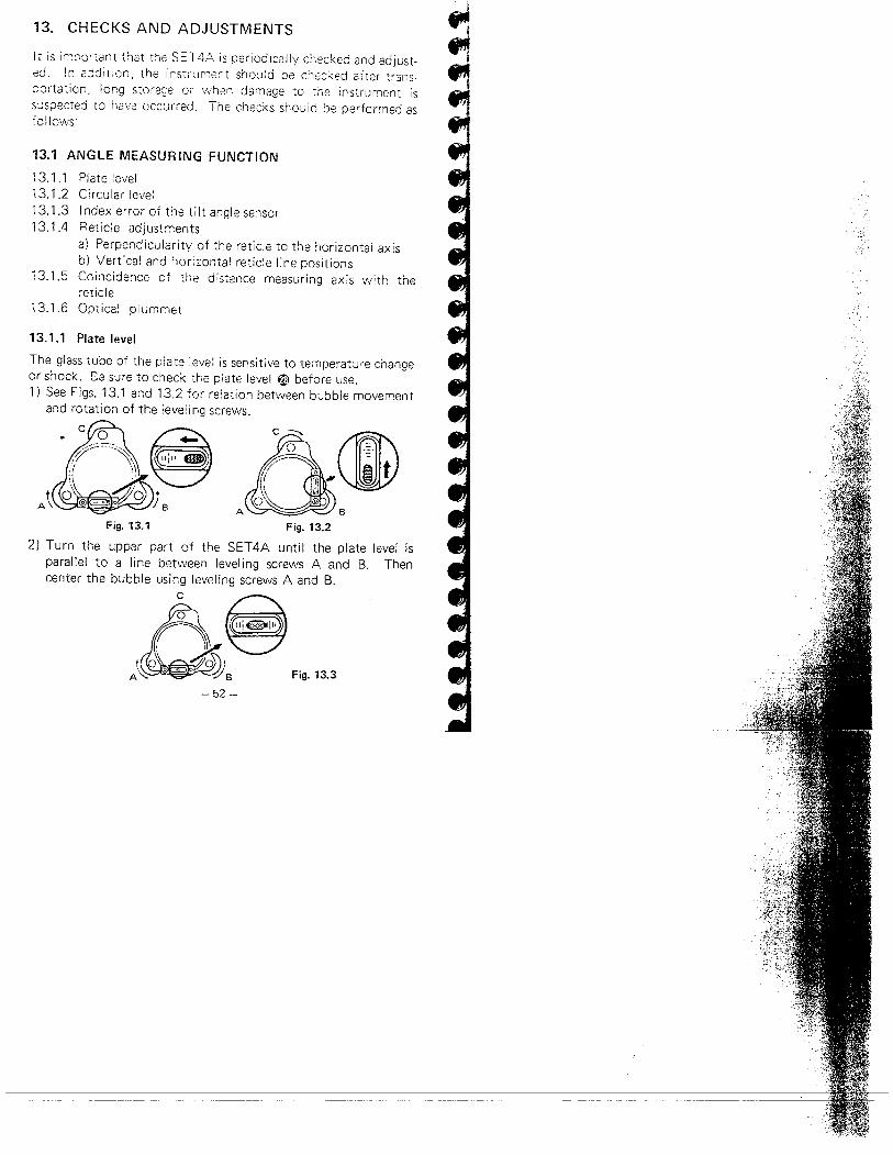
13.1.1 Plate level
The glass tube of the plate leve! is sensitive to temperature changeor shock. B-3 sure to check the piate level W before use.
1) See Figs. 13.1 and 13.2 for relation between bubble movementand rotation of the leveling screws.
C =:
il'~B
Fig. 13.1 Fig. 13.22) Turn the upper part of the SET4A until the plate level is
parallel to a line between leveling screws A and B. Thencenter the bubble usi ng level i ng screws A and B.
c
~.~to' ~iA ~ o. ¿; B Fig. 13.3
- 52-

l-..l-.te, _If
~
3) Turn the Jppe~ par: 900 un¡: tCie plate level is f-e~penjicu'2\-to a line between leveling screivs .A. and 3. Then center tiiebubble by turning leveling sc'e'N C.
Levell ing screw
A
~ ''''" ,,""" \l--0\8
Fig. 13.4
4) Turn the upper part 180°. Correct any bubble deviation by
half the amount with leveling screw C.
Óc (I"" -I
o ~, .I C. -~( i -- -=
oA BFig. 13.5
5) Correct the remaining half deviation by turning the plate leveladjusting screw W with the adjusting pin.
c
(l:.:."m
./ ~
AFig. 13.6
6) Repeat 2) to 5) above until the bubble remains centered for
any position of the upper part.
â,: (lo 0A BFig. 13.7
- 53-
;"-

13.1.2 Circular levelWhen the plate level adjustment is complete, the circular level æshould be checked. Note the direction off-center of the bubble.Loosen the adjusting screw 0 farthest from that direction andtighten the other adjusting screws to center the bubble. Ensurethat the tension of each screw tighten ing is the same after adjust-ment.
Fig. 13.8
13.1.3 Index error of the tilt angle sensorWhen the circular level adjustment is complete, the index errorshould be checked.
1) After indexing the vertical circle, tighten the vertical clamp ~.2) Press 9 then IX to set the horizontal circle to zero, then
press g to display the tilt angle.
,
n';:;" i n" Tilt angle a = -10"uuv IV
H ..('enn'n,."UL'UUU
Fig. 13.9
3) Loosen the horizontal clamp and turn the upper part through
180°:t 5'.
o'õ'õ'o 5"1 Tilt angle b = 5"
H ..
:so-ao'oo"
Fig. 13.10
-54-

..l-'l-'~'.r'
~,...,.;.~;~..,.,.l
a + b4) Calculate -- = index error c
- 1 0" + 5"Example: 2 = -2.5"5) If the index error is less than 5", no adjustment is necessary.
For adjustment remove the sensor index adjustment cover aD .Return to 00 horizontal angle position.Using a suitable flat screwdriver, adjust the internal screw until
the upper display doo = a-c.
Turn the upper part through 1800.
Adjust the internal screw until the upper display disoo = b - c.
Fig. 13.11
Example:-20" + (-10")If a = -20", b = -10", index error c = = -15"
2doo=a-c=-5"disoo = b -c = +5"
_ 0;0;_

13.1.4 Reticle adjustments
a) Perpendicularity of the reticle to the horizontal axis1) Select and sight a clear target on the upper part A of the
vertical reticle line, Fig. 13.12.2) Turn the telescope slowly upward with the vertical fine
motion screw ~ until the target slides to the lower part B,
Fig. 13.13. If the target is still centrally within the verticallines, no adjustment is necessary. If necessary, adjust as
follows.
Fig. 13.12 Fig. 13.13
3) Unscrew the reticle cover Kj.4) Slightly loosen one vertical and one horizontal adjusting screw
by a certain amount.5) Place a small piece of plastic or wood against one side of the
top adjusting screw as a buffer.6) Look through the eyepiece and gently tap the piece of plastic
or'Vood to rotate the reticle slightly.7) Re-tighten the two adjusting screws (loosened in 4)) by the
same amount. Check the reticle perpendicularity again andreadjust if necessary. Replace the reticle cover ~.
Fig. 13.14
_ i:¡:_

..l-l-.,.,.,...,.l-r-;e,.l-
l-....
b) Vertical and horizontal reticle line positionsWhen the index error adjustment is complete, the position of thereticle should be checked.1) Level the SET 4A. Select a clear target at a horizontal distance
of 200 to 300 feet.
lnn.mmmnmm'~O.:"oo.".mnmnnn....lFig. 13.15
2) After indexing the vertical circle, sight the target and take thehorizontal angle readi ng in position V1, e.g. a¡ = 18°34'00"
and the vertical angle reading, e.g. b¡ = 90°30'10".
Fig. 13.16
3) Next in position V2, sight the same target. Take the hori-zontal angle reading, e.g. ar= 198°34'10" and the verticalangle reading, e.g. br= 269°30'02".
4) Calculate ar-a¡, br+b¡.ar - a¡ = 198°34'10" - 18°34'00" = 180°00'10"br + b¡ = 269°30'02" + 90°30'10" = 360°00'12"
5) When the reticle is in the normal position, your results shouldshow that ar - a¡ is within 20" of 180° and br + b¡ is within
20" of 360°. If the difference of ar - a¡ from 180° or br + b¡from 360° is 20" or greater after several checks, adjust asfollows:
-'i7 _

6) While still in position V2, use the horizontal and vertical finemotion screws to adjust the lower display, ae, and the upperdisplay, be, to read:
ac = a¡ + ar + 9002
b - b¡b = r + 1800c 2Example:
If a¡ = 18°34'00"b¡ = 90°30'12"
ar = 198°34'26"br = 269°30'12"
18°34'00" + 198°34'26"2
+ 90°a¡ + a
a = -- + 90° =c 2= 198°34'13"
b -b¡ 269°30'12"-90°30'12"b = r + 180° = + 1800c 2 .2= 269°30'00"
7) Look through the telescope. The target is seen shifted fromthe vertical and horizontal reticle lines.
8) Remove the reticle adjustment cover ~ .
Adjusting screws
~
:~~Fig. 13.17
_ i:Q_
~Ifi
.,~-i

..~........'~i..)....~--" ../
~~~l.
..t- '-"~, -'~~
9) Adjust the reticle sideways with the adjusting screws until the
target is centrally within the vertical lines, and then adjust itup or down with the screws until the target is centrally withinthe horizontal lines.For example, to move the vertical reticle to the right (left)side, first slightly loosen the left (right) adjusting screw, thentighten the right (left) adjusting screw by the same amount.Repeat until the reticle comes close to the target center.In the same way, to move the horizontal reticle line down(up), slightly loosen the top (bottom) screw, then tighten thebottom (top) screw by the same amount and repeat until thereticle comes close to the target center.
t.. ~
lFig. 13.18 Fig. 13.19
10) Replace the reticle adjustment cover.
This adjustment is very delicate. If you find it difficult, pleasecontact our agent.
N.B. If amount of the reticle shift is too large, distancemeasuring may be affected. Do not adjust thereticle more than 20".
-59 -
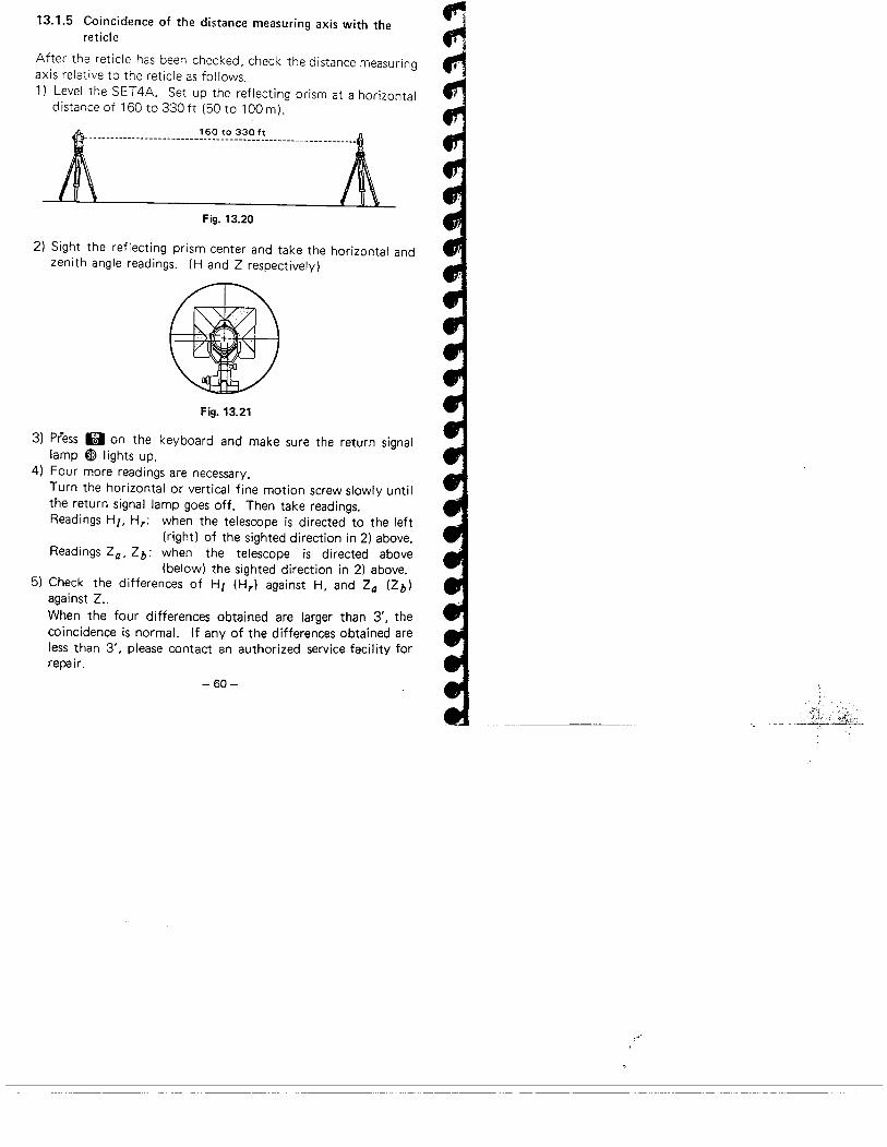
13.1.5 Coincidence of the distance measuring axis with thereticle
After the reticle has been checked, check the distance measuring
axis relative to the reticle as follows.
1) Level the SET 4A. Set up the reflecting prism at a horizontaldistance of 160to330ft (50 to 100m).
l.mmm..m..m."'.".".~'~"....m..m . l
-- ----..
Fig. 13.20
2) Sight the reflecting prism center and take the horizontal and
zenith angle readings. (H and Z respectively)
Fig. 13.21
3) press 13 on the keyboard and make sure the return signallamp ~ lights up.
4) Four more readings are necessary.Turn the horizontal or vertical fine motion screw slowly until
the return signal lamp goes off. Then take readings.
Readings Hi, Hr: when the telescope is directed to the left(right) of the sighted direction in 2) above.
Readings Za, Zb: when the telescope is directed above
(below) the sighted direction in 2) above.5) Check the differences of Hi (Hr) against H, and Za (Zb)
against Z.
When the four differences obtained are larger than 3', thecoincidence is normaL. If any of the differences obtained areless than 3', please contact an authorized service facility forrepair.
- 60-
~
¡,'

..
..
..
..
..,.,....",..-.-.-,.ïe
,.Ie~.".
13.1.6 Optical plummet
1) Level the SET4A. Center a surveying point in the reticle ojthe optical plummet. Loosen the horizontal clamp and turr
the upper part through 180°. If the surveying point is stillcentered, no adjustment is necessary.
2) If the surveying point is off-center, correct half the deviationwith the leveling screws and correct the remaining half with
the four adjusting screws. The screw adjusting procedure is
the same as the reticle adjustment 9) on page 59.
Fig. 13.22
3) Repeat the adjustment if necessary.
-61 -

13.2 DISTANCE MEASURING FUNCTION
13.2.1 Check flow chart
Beginning
Power switch ON
No
No
No
Press II
¡
No
Power switch OFF
No
No
No
No
Power switch OF F
Power mitch OFFContact our agent
Check is complete
Fig. 13.23
-62-
¡,'
........-l-.~~,~~..ll,,' I ,_ ._,..~.." ".-~~~.~
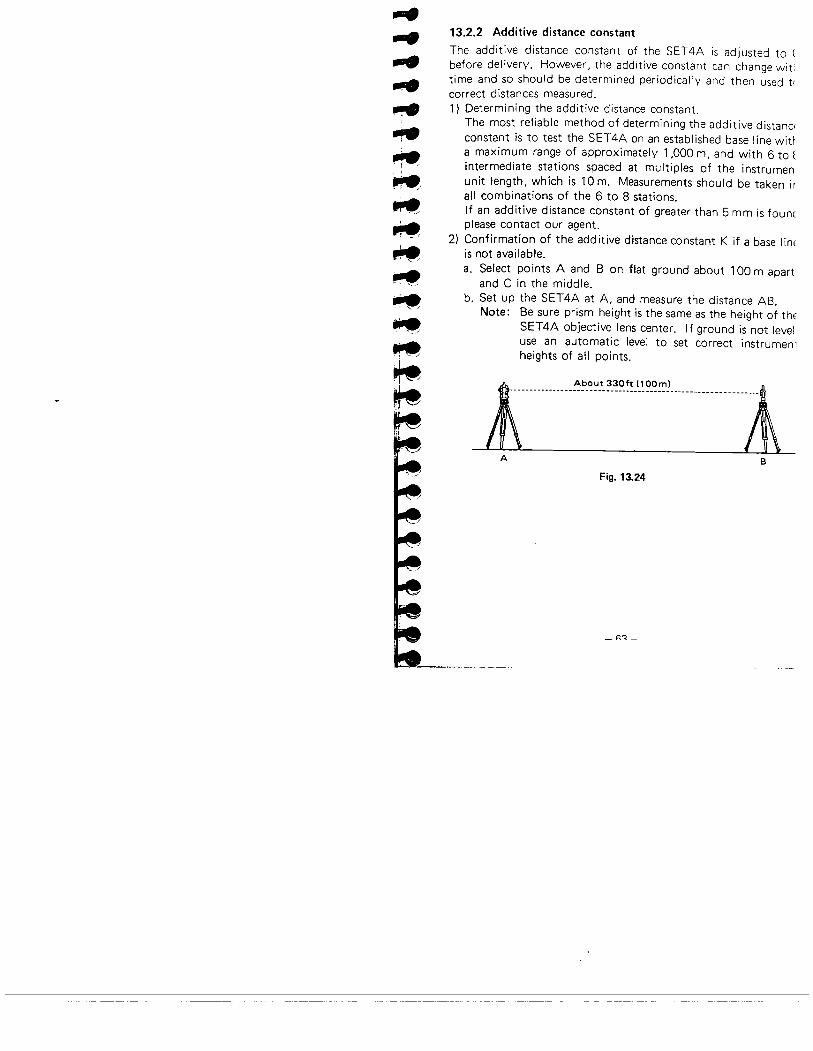
13.2.2 Additive distance constant
The additive distance constant of the SET4A is adjusted to (before del ivery. However, the additive constant can change wititime and so should be determined periodically and then used t(correct distances measured.1) Determining the additive distance constant.
The most reliable method of determining the additive distanciconstant is to test the SET4A on an established base line wiÜa maximum range of approximately 1,000 m, and with 6 to tintermediate stations spaced at multiples of the instrumen
unit length, which is 10m. Measurements should be taken irall combinations of the 6 to 8 stations.If an additive distance constant of greater than 5 mm is founcplease contact our agent.
2) Confirmation of the additive distance constant K if a base lintis not available.a. Select points A and B on flat ground about 100 m apart
and C in the middle.b. Set up the SET4A at A, and measure the distance AB.
Note: Be sure prism height is the same as the height of thtSET4A objective lens center. If ground is not leveluse an automatic level to set correct instrumen'heights of all points.
1\ AOO"'''''''OOml ¡'
. _umuuummmmm..ummuu.mmmmm
A B
Fig. 13.24
_ R':_

C. Shift the SET4A to C, and measure the distance CA andCB.
l......................i........................../tA c B
Fig. 13.25
d. Compute the additive distance error K using the formula:
K = AB - (CA + CB)
AB, CA, CB: Average of ten measurements.e. Obtain K value three times. If all K are greater than 5 mm,
contact our agent.
-R4 _
~
....l1..~
ì~,-l~~I.,..~¡"~ii~!I..
~~,."
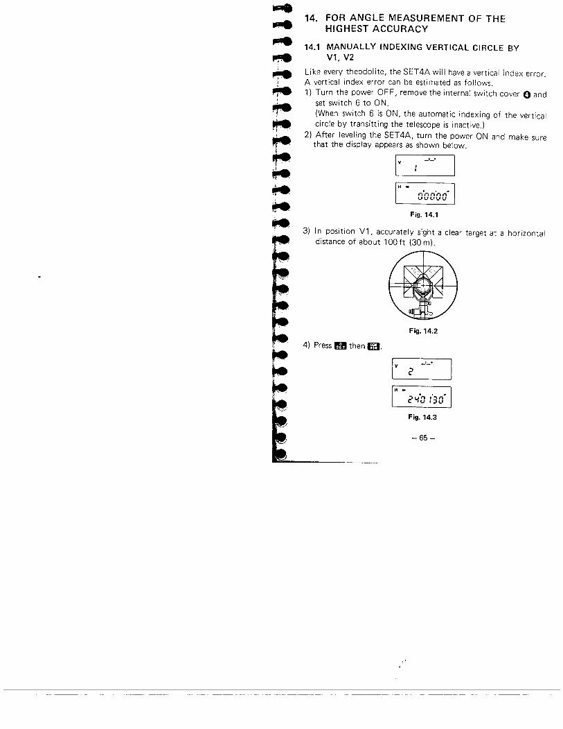
14. FOR ANGLE MEASUREMENT OF THEHIGHEST ACCURACY
14.1 MANUALLY INDEXING VERTICAL CIRCLE BYV1. V2
Like every theodolite, the SET4A will have a vertical index error.A vertical index error can be estimated as follows.
1) Turn the power OF F, remove the internal switch cover 0 andset switch 6 to ON.(When switch 6 is ON, the automatic indexing of the verticalcircle by transitting the telescope is inactive.)
2) After leveling the SET4A, turn the power ON and make surethat the display appears as shown below.
I v
_1_+
H Dn.,-. ,,'r..-.l..''-''-''-'t.1
Fig. 14.1
3) In position Vl, accurately sight a clear target at a horizontaldistance of about 100 ft (30 m).
Fig. 14.2
4) Press IB then m.
I v
_1_+
è
H ..
è'.IO :'30.
Fig. 14.3
-65 -

5) Next in position V2, accurately sight the same target.
Fig. 14.4
6) Press g then e. When the vertical circle is indexed, thedisplay appears as below.
Zenith angle_1_+
V 219''-9''-0''
Horizontalangle
H ..
20'-'0 :'30"
Fig. 14.5
. If the power switch has been turned OFF, the vertical circlemust be indexed again.When moving the SET4A after measurement, turn the powerOFF.
- 66-
~."f!
¡,"

-....~re,.,.~,~~~~~~
~,
~
15. FOR DISTANCE MEASUREMENT OF THEHIGHEST ACCURACY
15.1 ACCURACY OF MEASUREMENT OF ATMOSPHERICCONDITIONS
The relation between measured distance and the velocity of lightis given by
D=.2C=lfo2 2 nT: The period between light emission and reception.e: The velocity of light in the air.
eo: The velocity of light in a vacuum.n: Refractive index of the air.
The measured distance is affected by variation in the refractiveindex
dD dn . .0= - ~ ~ dn (or dD ~ D' dn)
Therefore, the accuracy of measurement of the refractive indexmust be the same as that of the measured distance.
To calculate refractive index to an accuracy of 2 ppm, tempera-ture must be measured to within 2°F (l°e) and pressure towithin 0.2 inchHg (5 mmHgl.
15.2 TO OBTAIN THE ATMOSPHERIC PRESSURE
To obtain the average refractive index of the air throughout themeasured light path, you should use the average atmospheric
pressure.If flat terrain there is little variation in the atmospheric pressure.In mountains, the following calculation should be used.
_ "-7_
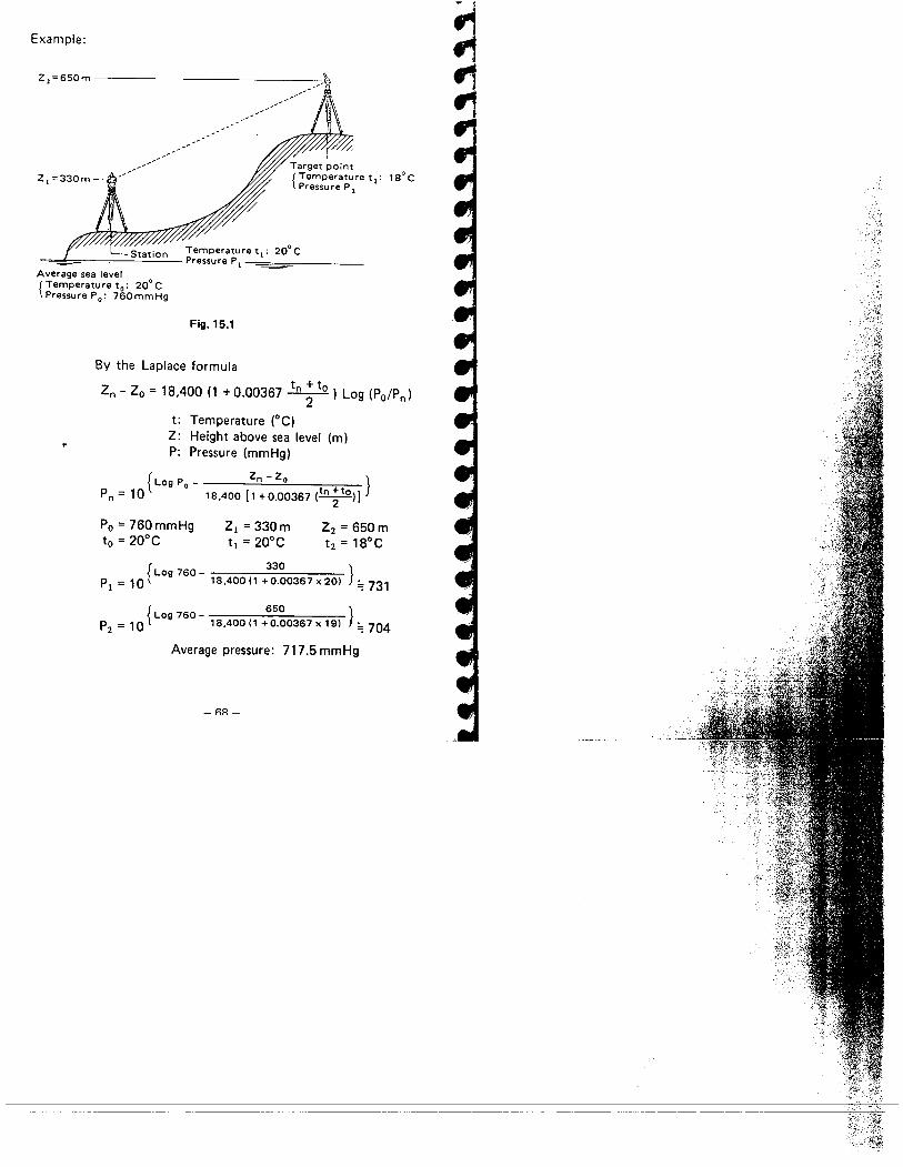
Example:
Z,=650m -
-'-'-'-',-'
18°CZ, =330m-
Temperature t,: 200 CPressure P i
Average sea level 0
(Temperature to: 20 CPressure Po: 760mmHg
Fig. 15.1
By the Laplace formula
Zn - Zo = 18,400 (1 +0.00367 tn ;to) Log (PO/Pn)
t: Temperature (OC)
Z: Height above sea level (m)P: Pressure (mmHg)
f zn - Zo )\ Log Po -Pn = 10 18,400 (, +0.00367 (tn;toi)
Po = 760 mmHgto = 20°C
Zi = 330mt¡ = 20°C
Z2 = 650mt2 = 18°C
f 3301 Log 760 - 18,400 (1 + 0.00367 x 20)Pi = 10 ) ~ 731
) ~ 704f 650Log 760 -P2 = 10 18,400(1 +0.00367x19)
Average pressure: 717.5 mmHg
-nA_
~"
.;:/~; _.~:~)':':'~. ,'. ~./~~:~':.''-'~~~-'~~-:'~~;

CIe
=
.....,.Ie".~..,..,.te
16. PRECAUTIONS AND MAINTENANCE
16.1 PRECAUTIONS
1) When the SET 4A is not used for a long time, check it at leastonce every three months.
2) Handle the SET 4A with care. Avoid heavy shocks or vibra-tion.
3) If any trouble is found on the rotatable portion, screws or
optical parts (e.g. lens). contact our agent.
4) When removing the SET4A from the carrying case, never pullit out by force. The empty carrying case should then be
closed to exclude dust.
5) Never place the SET4A directly on the ground.
6) Never carry the SET4A on the tripod another site.
7) Protect the SET4A with an umbrella against direct sunlight,rain and humidity.
8) When the operator leaves the SET4A, the vinyl cover shouldbe placed on the instrument.
9) Do not aim the telescope at the sun.
10) Always switch the power off before removing the internalbattery.
11) Always remove the battery from the SET4A when returningit to the case.
12) Do not wipe the display 0, keyboard æ or the carryingcase with an organic solvent.
13) When the SET4A is placed in the carrying case, follow thelayout plan.
14) Make sure that the SET4A and the protective lining of thecarrying case are dry before closing the case.
The case is hermetically sealed and if moisture is trappedinside, damage to the instrument could occur.
_RQ _

16.2 MAINTENANCE
1) Wipe off moisture completely if the instrument gets wet
during survey work.
2) Always clean the instrument before returning it to the case.
The lens requires special care. . Dust it off with the lensbrush first, to remove minute particles. Then, after pro-viding a little condensation by breathing on the lens,wipe it with soft clean cloth or lens tissue.
3) Store the SET4A in a dry room where the temperature re-mains fairly constant.
4) If the battery is discharged excessively, its I ife may be
shortened. Store it in a charged state.
5) Check the tripod for loose fit and loose screws.
_7(' _
~.,

...........
.-
.-l-.-!I~IeIe
E,.l-....Ie
17. ATMOSPHERIC CORRECTION CHARTS
(English)
(ppm)
130
120
110
100
90
80
70lL.. 60~a 50'"
8- 40EQ)
30I-
20
10
a
-10
-20
8§~~~~~~~~ ~~
~
~Ë0-
2-
'!
,~
'ß
id
18 19 20 21 22 23 24 25 26 27 28 29 30 31
Pressu re Ii nch Hg)
The chart shows the correction every two ppm, while the atmos-
pheric correction can be appl ied to the SET 4A for every ppm.
-71 -
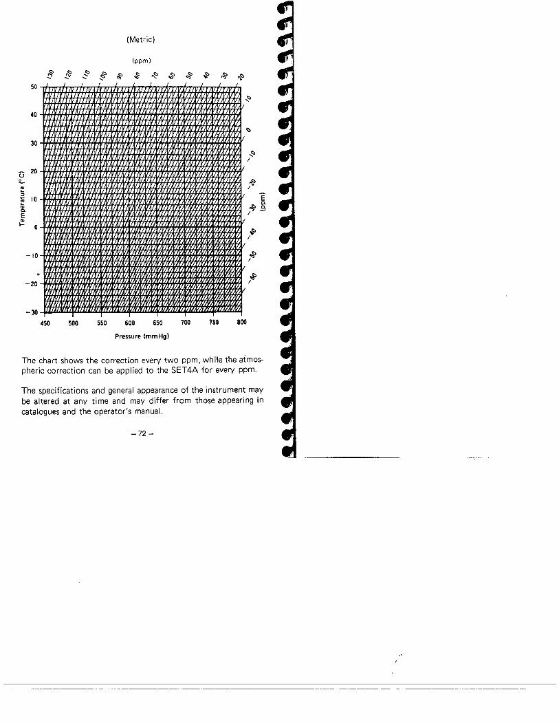
(Metric)
(ppm)
~ ~.. ~.. c§.. ~ ~ ~~ oâ .s~ ~so
~
40
30
Û 20o
~;!~ 10Q)0.EQ)i- a
-10
~
-20
-30450 750 800550 600 650 700500
Pressure (mmHgI
The chart shows the correction every two ppm, while the atmos-
pheric correction can be applied to the SET4A for every ppm.
The specifications and general appearance of the instrument maybe altered at any time and may differ from those appearing incatalogues and the operator's manuaL.
-72 -
I:
~/
~/E
.s 8:/ -
~/
~/
~/
r'"

----~........lil!.,.,~..i...t -
~t!~
18. INDEX
PagEAccessories............ .............. ..... . . .9,16,47
Angle measurement. . . . . . . . . . . . . . . . . . . . . . . . . . . . . . , . . 26Angle measurement modes . . . . . . . . . . . . . . . . . . . , . . . . . . . 27Atmospheric correction .....................,....... 32
Audio switch .........................,........... 35
Batteries ...........................,...........,. 16
Circular level adjustment ............................ 54
Curvature and refraction correction . . . , . . . . . . . . . . . . . . . . 34Display limit. . . . . . . . . . . . . . . . . . . . . . . . . , . . . . . . . . . . . . 33Display symbols ................................... 18
Distance measuring axis checking. . . . . . . . . . . . . . . . . . . . . . 60Distance measurement .............................. 37
Distance measurement checking. . . . . . . . . . . . . . . . . . . . . . . 63Distance measurement flow chart ..................... 62
Error codes . . . . . . . . . . . . . . . . . . . . . . . . . . . . . . . , . . . . . . . 45Features ......,.............,.................... 4
Focusing .................,..... . . . . . . . . . . . . . . . . . . 25Horizontal distance between two points ................ 44
Indexing manually ...,..........................,.. 65
Instrument part names '" , . . . . . . . . . . , . . . . . . . . . . . . . " 1Keyboard functions ................................ 19
Maintenance ...................................... 70
Optical plummet adjustment ......................... 61
Parallax . . . . . . . . . . . . . . . . . . . . , . . , . . . . . . . . . . . . . . . . . . 26Parts per million. . . . . . . . . . . , . . . . . . . . . , . . . . . . . . . . . . . 33Plate level adjustment. . . . . . . . . . . . . . . . . . . . . . . . . . . . . . . 52Power supplies .................................... 16
Powering up the SET4A . . . . . . . . . . . . . . . . . . . . . . . . . . . . . 23Precautions. . . . . , . . . . . . . . . . . . . . . . , . . . . . . . . . . . . . . . . 69Prism constant .................................... 31
Recalling data. . . . . . . . . . . . . , . . . . . . . . . . . . . . . . . . . . . . . 41Remote elevation measurement ......,...,............ 42
-73-

PageRepetition of angle. . . . . . . . . . . . . . . . . . . . . . . . . . . . . . . . . 29Reticle adjustment .".......,..,...,...,........... 56
Right and left angles. . . . . . . . . . . . . . . . . . . . . . . . . . . . . . . . 27Setting up over a point. . . . . . . . . . . . , . . . . . . . . . . . . . . . . . 25Specifications .........................,........... 5
Stake-out measurement. . . . . . . . . . . . . . . . . . . . . . . . . . . . . . 40Standard equipment ................................ 8
Switches, internal .................................. 20
Tilt angle sensor adjustment. . . . . . . . . . . . . . . . . . . . . . . . . . 54Tracking mode .................................... 36
Zenith angle compensation. . . . . . . . . . . . . . . . . . . . . . . . . . . 24
-74-
.,

....--ii.......,-,-.,.Ie..l-..-...-.-.l-
MEMO
..........................................................................................................................................
..........................................................................................................................................
..........................................................................................................................................
..........................................................................................................................................
..........................................................................................................................................
........................................................................................................................................
..........................................................................................................................................
..........................................................................................................................................
..........................................................................................................................................
..........................................................................................................................................
..........................................................................................................................................
MANUFACTURED BY
W SOKKISHA CO.. LTD.Keio Yoyogi Building 5th Floor. No.1. 1. 1-chome.Tomigaya. Shibuya-ku. Tokyo. 151 Japan
Telex: J28518SURSOK Cable: "SOKKISHÄ' TOKYOPhone: 03-485-2501 F'ax,: 03-465-5203