Embed Size (px)
Citation preview

ETX-202A Carrier Ethernet Demarcation Device
Version 1.2
INSTA
LLATIO
N A
ND
O
PER
ATIO
N M
AN
UA
L
The Access Company


ETX-202A Carrier Ethernet Demarcation Device
Version 1.2
Installation and Operation Manual
Notice
This manual contains information that is proprietary to RAD Data Communications Ltd. ("RAD"). No part of this publication may be reproduced in any form whatsoever without prior written approval by RAD Data Communications.
Right, title and interest, all information, copyrights, patents, know-how, trade secrets and other intellectual property or other proprietary rights relating to this manual and to the ETX-202A and any software components contained therein are proprietary products of RAD protected under international copyright law and shall be and remain solely with RAD.
The ETX-202A product name is owned by RAD. No right, license, or interest to such trademark is granted hereunder, and you agree that no such right, license, or interest shall be asserted by you with respect to such trademark. The RAD name, logo, logotype, and the terms EtherAccess, TDMoIP and TDMoIP Driven, and the product names Optimux and IPmux, are registered trademarks of RAD Data Communications Ltd. All other trademarks are the property of their respective holders.
You shall not copy, reverse compile or reverse assemble all or any portion of the Manual or the ETX-202A. You are prohibited from, and shall not, directly or indirectly, develop, market, distribute, license, or sell any product that supports substantially similar functionality as the ETX-202A, based on or derived in any way from the ETX-202A. Your undertaking in this paragraph shall survive the termination of this Agreement.
This Agreement is effective upon your opening of the ETX-202A package and shall continue until terminated. RAD may terminate this Agreement upon the breach by you of any term hereof. Upon such termination by RAD, you agree to return to RAD the ETX-202A and all copies and portions thereof.
For further information contact RAD at the address below or contact your local distributor.
International Headquarters RAD Data Communications Ltd.
24 Raoul Wallenberg Street Tel Aviv 69719, Israel Tel: 972-3-6458181 Fax: 972-3-6498250, 6474436 E-mail: [email protected]
North America Headquarters RAD Data Communications Inc.
900 Corporate Drive Mahwah, NJ 07430, USA Tel: (201) 5291100, Toll free: 1-800-4447234 Fax: (201) 5295777 E-mail: [email protected]
© 2004–2008 RAD Data Communications Ltd. Publication No. 402-200-08/08

Limited Warranty
RAD warrants to DISTRIBUTOR that the hardware in the ETX-202A to be delivered hereunder shall be free of defects in material and workmanship under normal use and service for a period of twelve (12) months following the date of shipment to DISTRIBUTOR.
If, during the warranty period, any component part of the equipment becomes defective by reason of material or workmanship, and DISTRIBUTOR immediately notifies RAD of such defect, RAD shall have the option to choose the appropriate corrective action: a) supply a replacement part, or b) request return of equipment to its plant for repair, or c) perform necessary repair at the equipment's location. In the event that RAD requests the return of equipment, each party shall pay one-way shipping costs.
RAD shall be released from all obligations under its warranty in the event that the equipment has been subjected to misuse, neglect, accident or improper installation, or if repairs or modifications were made by persons other than RAD's own authorized service personnel, unless such repairs by others were made with the written consent of RAD.
The above warranty is in lieu of all other warranties, expressed or implied. There are no warranties which extend beyond the face hereof, including, but not limited to, warranties of merchantability and fitness for a particular purpose, and in no event shall RAD be liable for consequential damages.
RAD shall not be liable to any person for any special or indirect damages, including, but not limited to, lost profits from any cause whatsoever arising from or in any way connected with the manufacture, sale, handling, repair, maintenance or use of the ETX-202A, and in no event shall RAD's liability exceed the purchase price of the ETX-202A.
DISTRIBUTOR shall be responsible to its customers for any and all warranties which it makes relating to ETX-202A and for ensuring that replacements and other adjustments required in connection with the said warranties are satisfactory.
Software components in the ETX-202A are provided "as is" and without warranty of any kind. RAD disclaims all warranties including the implied warranties of merchantability and fitness for a particular purpose. RAD shall not be liable for any loss of use, interruption of business or indirect, special, incidental or consequential damages of any kind. In spite of the above RAD shall do its best to provide error-free software products and shall offer free Software updates during the warranty period under this Agreement.
RAD's cumulative liability to you or any other party for any loss or damages resulting from any claims, demands, or actions arising out of or relating to this Agreement and the ETX-202A shall not exceed the sum paid to RAD for the purchase of the ETX-202A. In no event shall RAD be liable for any indirect, incidental, consequential, special, or exemplary damages or lost profits, even if RAD has been advised of the possibility of such damages.
This Agreement shall be construed and governed in accordance with the laws of the State of Israel.
Product Disposal
To facilitate the reuse, recycling and other forms of recovery of waste equipment in protecting the environment, the owner of this RAD product is required to refrain from disposing of this product as unsorted municipal waste at the end of its life cycle. Upon termination of the unit’s use, customers should provide for its collection for reuse, recycling or other form of environmentally conscientious disposal.

General Safety Instructions
The following instructions serve as a general guide for the safe installation and operation of telecommunications products. Additional instructions, if applicable, are included inside the manual.
Safety Symbols
This symbol may appear on the equipment or in the text. It indicates potential safety hazards regarding product operation or maintenance to operator or service personnel.
Danger of electric shock! Avoid any contact with the marked surface while the product is energized or connected to outdoor telecommunication lines.
Protective ground: the marked lug or terminal should be connected to the building protective ground bus.
Some products may be equipped with a laser diode. In such cases, a label with the laser class and other warnings as applicable will be attached near the optical transmitter. The laser warning symbol may be also attached.
Please observe the following precautions:
• Before turning on the equipment, make sure that the fiber optic cable is intact and is connected to the transmitter.
• Do not attempt to adjust the laser drive current.
• Do not use broken or unterminated fiber-optic cables/connectors or look straight at the laser beam.
• The use of optical devices with the equipment will increase eye hazard.
• Use of controls, adjustments or performing procedures other than those specified herein, may result in hazardous radiation exposure.
ATTENTION: The laser beam may be invisible!
In some cases, the users may insert their own SFP laser transceivers into the product. Users are alerted that RAD cannot be held responsible for any damage that may result if non-compliant transceivers are used. In particular, users are warned to use only agency approved products that comply with the local laser safety regulations for Class 1 laser products.
Always observe standard safety precautions during installation, operation and maintenance of this product. Only qualified and authorized service personnel should carry out adjustment, maintenance or repairs to this product. No installation, adjustment, maintenance or repairs should be performed by either the operator or the user.
Warning
Warning

Handling Energized Products
General Safety Practices
Do not touch or tamper with the power supply when the power cord is connected. Line voltages may be present inside certain products even when the power switch (if installed) is in the OFF position or a fuse is blown. For DC-powered products, although the voltages levels are usually not hazardous, energy hazards may still exist.
Before working on equipment connected to power lines or telecommunication lines, remove jewelry or any other metallic object that may come into contact with energized parts.
Unless otherwise specified, all products are intended to be grounded during normal use. Grounding is provided by connecting the mains plug to a wall socket with a protective ground terminal. If a ground lug is provided on the product, it should be connected to the protective ground at all times, by a wire with a diameter of 18 AWG or wider. Rack-mounted equipment should be mounted only in grounded racks and cabinets.
Always make the ground connection first and disconnect it last. Do not connect telecommunication cables to ungrounded equipment. Make sure that all other cables are disconnected before disconnecting the ground.
Some products may have panels secured by thumbscrews with a slotted head. These panels may cover hazardous circuits or parts, such as power supplies. These thumbscrews should therefore always be tightened securely with a screwdriver after both initial installation and subsequent access to the panels.
Connecting AC Mains
Make sure that the electrical installation complies with local codes.
Always connect the AC plug to a wall socket with a protective ground.
The maximum permissible current capability of the branch distribution circuit that supplies power to the product is 16A. The circuit breaker in the building installation should have high breaking capacity and must operate at short-circuit current exceeding 35A.
Always connect the power cord first to the equipment and then to the wall socket. If a power switch is provided in the equipment, set it to the OFF position. If the power cord cannot be readily disconnected in case of emergency, make sure that a readily accessible circuit breaker or emergency switch is installed in the building installation.
In cases when the power distribution system is IT type, the switch must disconnect both poles simultaneously.
Connecting DC Power
Unless otherwise specified in the manual, the DC input to the equipment is floating in reference to the ground. Any single pole can be externally grounded.
Due to the high current capability of DC power systems, care should be taken when connecting the DC supply to avoid short-circuits and fire hazards.
DC units should be installed in a restricted access area, i.e. an area where access is authorized only to qualified service and maintenance personnel.
Make sure that the DC power supply is electrically isolated from any AC source and that the installation complies with the local codes.

The maximum permissible current capability of the branch distribution circuit that supplies power to the product is 16A. The circuit breaker in the building installation should have high breaking capacity and must operate at short-circuit current exceeding 35A.
Before connecting the DC supply wires, ensure that power is removed from the DC circuit. Locate the circuit breaker of the panel board that services the equipment and switch it to the OFF position. When connecting the DC supply wires, first connect the ground wire to the corresponding terminal, then the positive pole and last the negative pole. Switch the circuit breaker back to the ON position.
A readily accessible disconnect device that is suitably rated and approved should be incorporated in the building installation.
If the DC power supply is floating, the switch must disconnect both poles simultaneously.
Connecting Data and Telecommunications Cables
Data and telecommunication interfaces are classified according to their safety status.
The following table lists the status of several standard interfaces. If the status of a given port differs from the standard one, a notice will be given in the manual.
Ports Safety Status
V.11, V.28, V.35, V.36, RS-530, X.21, 10 BaseT, 100 BaseT, Unbalanced E1, E2, E3, STM, DS-2, DS-3, S-Interface ISDN, Analog voice E&M
SELV Safety Extra Low Voltage:
Ports which do not present a safety hazard. Usually up to 30 VAC or 60 VDC.
xDSL (without feeding voltage), Balanced E1, T1, Sub E1/T1
TNV-1 Telecommunication Network Voltage-1:
Ports whose normal operating voltage is within the limits of SELV, on which overvoltages from telecommunications networks are possible.
FXS (Foreign Exchange Subscriber) TNV-2 Telecommunication Network Voltage-2:
Ports whose normal operating voltage exceeds the limits of SELV (usually up to 120 VDC or telephone ringing voltages), on which overvoltages from telecommunication networks are not possible. These ports are not permitted to be directly connected to external telephone and data lines.
FXO (Foreign Exchange Office), xDSL (with feeding voltage), U-Interface ISDN
TNV-3 Telecommunication Network Voltage-3:
Ports whose normal operating voltage exceeds the limits of SELV (usually up to 120 VDC or telephone ringing voltages), on which overvoltages from telecommunication networks are possible.
Always connect a given port to a port of the same safety status. If in doubt, seek the assistance of a qualified safety engineer.
Always make sure that the equipment is grounded before connecting telecommunication cables. Do not disconnect the ground connection before disconnecting all telecommunications cables.
Some SELV and non-SELV circuits use the same connectors. Use caution when connecting cables. Extra caution should be exercised during thunderstorms.

When using shielded or coaxial cables, verify that there is a good ground connection at both ends. The grounding and bonding of the ground connections should comply with the local codes.
The telecommunication wiring in the building may be damaged or present a fire hazard in case of contact between exposed external wires and the AC power lines. In order to reduce the risk, there are restrictions on the diameter of wires in the telecom cables, between the equipment and the mating connectors.
To reduce the risk of fire, use only No. 26 AWG or larger telecommunication line cords.
Pour réduire les risques s’incendie, utiliser seulement des conducteurs de télécommunications 26 AWG ou de section supérieure.
Some ports are suitable for connection to intra-building or non-exposed wiring or cabling only. In such cases, a notice will be given in the installation instructions.
Do not attempt to tamper with any carrier-provided equipment or connection hardware.
Electromagnetic Compatibility (EMC)
The equipment is designed and approved to comply with the electromagnetic regulations of major regulatory bodies. The following instructions may enhance the performance of the equipment and will provide better protection against excessive emission and better immunity against disturbances.
A good ground connection is essential. When installing the equipment in a rack, make sure to remove all traces of paint from the mounting points. Use suitable lock-washers and torque. If an external grounding lug is provided, connect it to the ground bus using braided wire as short as possible.
The equipment is designed to comply with EMC requirements when connecting it with unshielded twisted pair (UTP) cables. However, the use of shielded wires is always recommended, especially for high-rate data. In some cases, when unshielded wires are used, ferrite cores should be installed on certain cables. In such cases, special instructions are provided in the manual.
Disconnect all wires which are not in permanent use, such as cables used for one-time configuration.
The compliance of the equipment with the regulations for conducted emission on the data lines is dependent on the cable quality. The emission is tested for UTP with 80 dB longitudinal conversion loss (LCL).
Unless otherwise specified or described in the manual, TNV-1 and TNV-3 ports provide secondary protection against surges on the data lines. Primary protectors should be provided in the building installation.
The equipment is designed to provide adequate protection against electro-static discharge (ESD). However, it is good working practice to use caution when connecting cables terminated with plastic connectors (without a grounded metal hood, such as flat cables) to sensitive data lines. Before connecting such cables, discharge yourself by touching ground or wear an ESD preventive wrist strap.
Caution
Attention

FCC-15 User Information
This equipment has been tested and found to comply with the limits of the Class A digital device, pursuant to Part 15 of the FCC rules. These limits are designed to provide reasonable protection against harmful interference when the equipment is operated in a commercial environment. This equipment generates, uses and can radiate radio frequency energy and, if not installed and used in accordance with the Installation and Operation manual, may cause harmful interference to the radio communications. Operation of this equipment in a residential area is likely to cause harmful interference in which case the user will be required to correct the interference at his own expense.
Canadian Emission Requirements
This Class A digital apparatus meets all the requirements of the Canadian Interference-Causing Equipment Regulation.
Cet appareil numérique de la classe A respecte toutes les exigences du Règlement sur le matériel brouilleur du Canada.
Warning per EN 55022 (CISPR-22)
This is a class A product. In a domestic environment, this product may cause radio interference, in which case the user will be required to take adequate measures.
Cet appareil est un appareil de Classe A. Dans un environnement résidentiel, cet appareil peut provoquer des brouillages radioélectriques. Dans ces cas, il peut être demandé à l’utilisateur de prendre les mesures appropriées.
Das vorliegende Gerät fällt unter die Funkstörgrenzwertklasse A. In Wohngebieten können beim Betrieb dieses Gerätes Rundfunkströrungen auftreten, für deren Behebung der Benutzer verantwortlich ist.
Warning
Avertissement
Achtung

Fra
nça
is
Mise au rebut du produit
Afin de faciliter la réutilisation, le recyclage ainsi que d'autres formes de récupération d'équipement mis au rebut dans le cadre de la protection de l'environnement, il est demandé au propriétaire de ce produit RAD de ne pas mettre ce dernier au rebut en tant que déchet municipal non trié, une fois que le produit est arrivé en fin de cycle de vie. Le client devrait proposer des solutions de réutilisation, de recyclage ou toute autre forme de mise au rebut de cette unité dans un esprit de protection de l'environnement, lorsqu'il aura fini de l'utiliser.
Instructions générales de sécurité
Les instructions suivantes servent de guide général d'installation et d'opération sécurisées des produits de télécommunications. Des instructions supplémentaires sont éventuellement indiquées dans le manuel.
Symboles de sécurité
Ce symbole peut apparaitre sur l'équipement ou dans le texte. Il indique des risques potentiels de sécurité pour l'opérateur ou le personnel de service, quant à l'opération du produit ou à sa maintenance.
Danger de choc électrique ! Evitez tout contact avec la surface marquée tant que le produit est sous tension ou connecté à des lignes externes de télécommunications.
Mise à la terre de protection : la cosse ou la borne marquée devrait être connectée à la prise de terre de protection du bâtiment.
Avertissement

Fra
nça
is
Certains produits peuvent être équipés d'une diode laser. Dans de tels cas, une étiquette indiquant la classe laser ainsi que d'autres avertissements, le cas échéant, sera jointe près du transmetteur optique. Le symbole d'avertissement laser peut aussi être joint.
Veuillez observer les précautions suivantes :
• Avant la mise en marche de l'équipement, assurez-vous que le câble de fibre optique est intact et qu'il est connecté au transmetteur.
• Ne tentez pas d'ajuster le courant de la commande laser.
• N'utilisez pas des câbles ou connecteurs de fibre optique cassés ou sans terminaison et n'observez pas directement un rayon laser.
• L'usage de périphériques optiques avec l'équipement augmentera le risque pour les yeux.
• L'usage de contrôles, ajustages ou procédures autres que celles spécifiées ici pourrait résulter en une dangereuse exposition aux radiations.
ATTENTION : Le rayon laser peut être invisible !
Les utilisateurs pourront, dans certains cas, insérer leurs propres émetteurs-récepteurs Laser SFP dans le produit. Les utilisateurs sont avertis que RAD ne pourra pas être tenue responsable de tout dommage pouvant résulter de l'utilisation d'émetteurs-récepteurs non conformes. Plus particulièrement, les utilisateurs sont avertis de n'utiliser que des produits approuvés par l'agence et conformes à la réglementation locale de sécurité laser pour les produits laser de classe 1.
Respectez toujours les précautions standards de sécurité durant l'installation, l'opération et la maintenance de ce produit. Seul le personnel de service qualifié et autorisé devrait effectuer l'ajustage, la maintenance ou les réparations de ce produit. Aucune opération d'installation, d'ajustage, de maintenance ou de réparation ne devrait être effectuée par l'opérateur ou l'utilisateur.
Manipuler des produits sous tension
Règles générales de sécurité
Ne pas toucher ou altérer l'alimentation en courant lorsque le câble d'alimentation est branché. Des tensions de lignes peuvent être présentes dans certains produits, même lorsque le commutateur (s'il est installé) est en position OFF ou si le fusible est rompu. Pour les produits alimentés par CC, les niveaux de tension ne sont généralement pas dangereux mais des risques de courant peuvent toujours exister.
Avant de travailler sur un équipement connecté aux lignes de tension ou de télécommunications, retirez vos bijoux ou tout autre objet métallique pouvant venir en contact avec les pièces sous tension.
Sauf s'il en est autrement indiqué, tous les produits sont destinés à être mis à la terre durant l'usage normal. La mise à la terre est fournie par la connexion de la fiche principale à une prise murale équipée d'une borne protectrice de mise à la terre. Si une cosse de mise à la terre est fournie avec le produit, elle devrait être connectée à tout moment à une mise à la terre de protection par un conducteur de diamètre 18 AWG ou plus. L'équipement monté en châssis ne devrait être monté que sur des châssis et dans des armoires mises à la terre.
Branchez toujours la mise à la terre en premier et débranchez-la en dernier. Ne branchez pas des câbles de télécommunications à un équipement qui n'est pas mis à la terre. Assurez-vous que tous les autres câbles sont débranchés avant de déconnecter la mise à la terre.
Avertissement
Fra
nça
is
Connexion au courant du secteur
Assurez-vous que l'installation électrique est conforme à la réglementation locale.
Branchez toujours la fiche de secteur à une prise murale équipée d'une borne protectrice de mise à la terre.
La capacité maximale permissible en courant du circuit de distribution de la connexion alimentant le produit est de 16A. Le coupe-circuit dans l'installation du bâtiment devrait avoir une capacité élevée de rupture et devrait fonctionner sur courant de court-circuit dépassant 35A.
Branchez toujours le câble d'alimentation en premier à l'équipement puis à la prise murale. Si un commutateur est fourni avec l'équipement, fixez-le en position OFF. Si le câble d'alimentation ne peut pas être facilement débranché en cas d'urgence, assurez-vous qu'un coupe-circuit ou un disjoncteur d'urgence facilement accessible est installé dans l'installation du bâtiment.
Le disjoncteur devrait déconnecter simultanément les deux pôles si le système de distribution de courant est de type IT.
Connexion d'alimentation CC
Sauf s'il en est autrement spécifié dans le manuel, l'entrée CC de l'équipement est flottante par rapport à la mise à la terre. Tout pôle doit être mis à la terre en externe.
A cause de la capacité de courant des systèmes à alimentation CC, des précautions devraient être prises lors de la connexion de l'alimentation CC pour éviter des courts-circuits et des risques d'incendie.
Les unités CC devraient être installées dans une zone à accès restreint, une zone où l'accès n'est autorisé qu'au personnel qualifié de service et de maintenance.
Assurez-vous que l'alimentation CC est isolée de toute source de courant CA (secteur) et que l'installation est conforme à la réglementation locale.
La capacité maximale permissible en courant du circuit de distribution de la connexion alimentant le produit est de 16A. Le coupe-circuit dans l'installation du bâtiment devrait avoir une capacité élevée de rupture et devrait fonctionner sur courant de court-circuit dépassant 35A.
Avant la connexion des câbles d'alimentation en courant CC, assurez-vous que le circuit CC n'est pas sous tension. Localisez le coupe-circuit dans le tableau desservant l'équipement et fixez-le en position OFF. Lors de la connexion de câbles d'alimentation CC, connectez d'abord le conducteur de mise à la terre à la borne correspondante, puis le pôle positif et en dernier, le pôle négatif. Remettez le coupe-circuit en position ON.
Un disjoncteur facilement accessible, adapté et approuvé devrait être intégré à l'installation du bâtiment.
Le disjoncteur devrait déconnecter simultanément les deux pôles si l'alimentation en courant CC est flottante.

Declaration of Conformity
Manufacturer's Name: RAD Data Communications Ltd.
Manufacturer's Address: 24 Raoul Wallenberg St. Tel Aviv 69719 Israel
Declares that the product:
Product Name: ETX-202A, ETX-202A/H
Conforms to the following standard(s) or other normative document(s):
EMC: EN 55022:2006 Information technology equipment – Radio disturbance characteristics – Limits and methods of measurement.
EN 55024: 1998 + A1:2001, A2:2003
Information technology equipment – Immunity characteristics – Limits and methods of measurement.
EN 61000-3-2:2000 + A2:2005
Electromagnetic compatibility (EMC) –Part 3-2: Limits – Limits for harmonic current emissions (equipment input current up to and including 16A per phase).
EN 61000-3-3:1995 + A1:2001
Electromagnetic compatibility (EMC) –Part 3-3: Limits – Limitation of voltage changes, voltage fluctuations and flicker in public low-voltage supply systems, for equipment with rated current ≤ 16A per phase and not subject to conditional connection.
Safety: EN 60950-1:2001 + A11:2004
Information technology equipment – Safety – Part 1: General requirements
Supplementary Information:
The products herewith comply with the requirements of the EMC Directive 2004/108/EC, the Low Voltage Directive 2006/95/EC and the R&TTE Directive 99/5/EC for wired equipment. The products were tested in a typical configuration.
Tel Aviv, 7 August 2008
Haim Karshen VP Quality
European Contact: RAD Data Communications GmbH Otto-Hahn-Str. 28-30, 85521 Ottobrunn-Riemerling, Germany

Glossary
Address A coded representation of the origin or destination of data.
Agent In SNMP, this refers to the managed system.
Analog A continuous wave or signal (such as human voice).
ANSI American National Standards Institute.
AWG The American Wire Gauge System, which specifies wire width.
Balanced A transmission line in which voltages on the two conductors are equal in magnitude, but opposite in polarity, with respect to ground.
Bandwidth The range of frequencies passing through a given circuit. The greater the bandwidth, the more information can be sent through the circuit in a given amount of time.
Baud Unit of signaling speed equivalent to the number of discrete conditions or events per second. If each signal event represents only one bit condition, baud rate equals bps (bits per second).
Bit The smallest unit of information in a binary system. Represents either a one or zero (“1” or “0”).
Bit Interleaving/Multiplexing
A process used in time division multiplexing where individual bits from different lower speed channel sources are combined (one bit from one channel at a time) into one continuous higher speed bit stream.
bps (Bits Per Second) A measure of data transmission rate in serial transmission.
Bridge A device interconnecting local area networks at the OSI data link layer, filtering and forwarding frames according to media access control (MAC) addresses.
Bus A transmission path or channel. A bus is typically an electrical connection with one or more conductors, where all attached devices receive all transmissions at the same time.
Byte A group of bits (normally 8 bits in length).
Carrier A continuous signal at a fixed frequency that is capable of being modulated with a second (information carrying) signal.
Cell The 53-byte basic information unit within an ATM network. The user traffic is segmented into cells at the source and reassembled at the destination. An ATM cell consists of a 5-byte ATM header and a 48-byte ATM payload, which contains the user data.
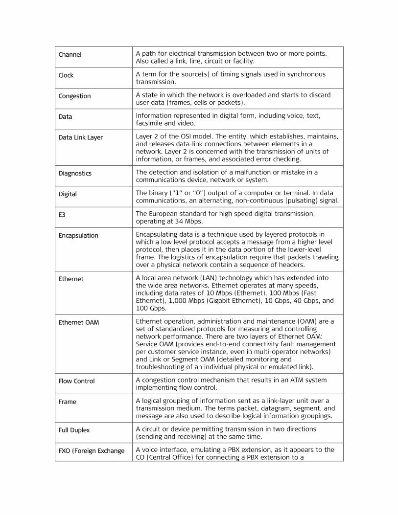
Channel A path for electrical transmission between two or more points. Also called a link, line, circuit or facility.
Clock A term for the source(s) of timing signals used in synchronous transmission.
Congestion A state in which the network is overloaded and starts to discard user data (frames, cells or packets).
Data Information represented in digital form, including voice, text, facsimile and video.
Data Link Layer Layer 2 of the OSI model. The entity, which establishes, maintains, and releases data-link connections between elements in a network. Layer 2 is concerned with the transmission of units of information, or frames, and associated error checking.
Diagnostics The detection and isolation of a malfunction or mistake in a communications device, network or system.
Digital The binary (“1” or “0”) output of a computer or terminal. In data communications, an alternating, non-continuous (pulsating) signal.
E3 The European standard for high speed digital transmission, operating at 34 Mbps.
Encapsulation Encapsulating data is a technique used by layered protocols in which a low level protocol accepts a message from a higher level protocol, then places it in the data portion of the lower-level frame. The logistics of encapsulation require that packets traveling over a physical network contain a sequence of headers.
Ethernet A local area network (LAN) technology which has extended into the wide area networks. Ethernet operates at many speeds, including data rates of 10 Mbps (Ethernet), 100 Mbps (Fast Ethernet), 1,000 Mbps (Gigabit Ethernet), 10 Gbps, 40 Gbps, and 100 Gbps.
Ethernet OAM Ethernet operation, administration and maintenance (OAM) are a set of standardized protocols for measuring and controlling network performance. There are two layers of Ethernet OAM: Service OAM (provides end-to-end connectivity fault management per customer service instance, even in multi-operator networks) and Link or Segment OAM (detailed monitoring and troubleshooting of an individual physical or emulated link).
Flow Control A congestion control mechanism that results in an ATM system implementing flow control.
Frame A logical grouping of information sent as a link-layer unit over a transmission medium. The terms packet, datagram, segment, and message are also used to describe logical information groupings.
Full Duplex A circuit or device permitting transmission in two directions (sending and receiving) at the same time.
FXO (Foreign Exchange A voice interface, emulating a PBX extension, as it appears to the CO (Central Office) for connecting a PBX extension to a

Office) multiplexer.
FXS (Foreign Exchange Subscriber)
A voice interface, emulating the extension interface of a PBX (or subscriber interface of a CO) for connecting a regular telephone set to a multiplexer.
Gateway Gateways are points of entrance and exit from a communications network. Viewed as a physical entity, a gateway is that node that translates between two otherwise incompatible networks or network segments. Gateways perform code and protocol conversion to facilitate traffic between data highways of differing architecture.
Half Duplex A circuit or device capable of transmitting in two directions, but not at the same time.
Interface A shared boundary, defined by common physical interconnection characteristics, signal characteristics, and meanings of exchanged signals.
IP Address Also known as an Internet address. A unique string of numbers that identifies a computer or device on a TCP/IP network. The format of an IP address is a 32-bit numeric address written as four numbers from 0 to 255, separated by periods (for example, 1.0.255.123).
Jitter The deviation of a transmission signal in time or phase. It can introduce errors and loss of synchronization in high speed synchronous communications.
Laser A device that transmits an extremely narrow and coherent beam of electromagnetic energy in the visible light spectrum. Used as a light source for fiber optic transmission (generally more expensive, shorter lived, single mode only, for greater distances than LED).
Loopback A type of diagnostic test in which the transmitted signal is returned to the sending device after passing through all or part of a communications link or network.
Manager An application that receives Simple Network Management Protocol (SNMP) information from an agent. An agent and manager share a database of information, called the Management Information Base (MIB). An agent can use a message called a traps-PDU to send unsolicited information to the manager. A manager that uses the RADview MIB can query the RAD device, set parameters, sound alarms when certain conditions appear, and perform other administrative tasks.
Multiplexer At one end of a communications link, a device that combines several lower speed transmission channels into a single high speed channel. A multiplexer at the other end reverses the process. Sometimes called a mux. See Bit Interleaving/Multiplexing.
Network (1) An interconnected group of nodes. (2) A series of points, nodes, or stations connected by communications channels; the collection of equipment through which connections are made between data stations.

Node A point of interconnection to a network.
Packet An ordered group of data and control signals transmitted through a network, as a subset of a larger message.
parameters Parameters are often called arguments, and the two words are used interchangeably. However, some computer languages such as C define argument to mean actual parameter (i.e., the value), and parameter to mean formal parameter. In RAD CLI, parameter means formal parameter, not value.
Payload The 48-byte segment of the ATM cell containing user data. Any adaptation of user data via the AAL will take place within the payload.
Physical Layer Layer 1 of the OSI model. The layer concerned with electrical, mechanical, and handshaking procedures over the interface connecting a device to the transmission medium.
Policing A method for verifying that the incoming VC complies with the user’s service contract.
Port The physical interface to a computer or multiplexer, for connection of terminals and modems.
Prioritization Also called CoS (class of service), classifies traffic into categories such as high, medium, and low. The lower the priority, the more “drop eligible” is a packet. When the network gets busy, prioritization ensures critical or high-rated traffic is passed first, and packets from the lowest categories may be dropped.
Protocol A formal set of conventions governing the formatting and relative timing of message exchange between two communicating systems.
Router An interconnection device that connects individual LANs. Unlike bridges, which logically connect at OSI Layer 2, routers provide logical paths at OSI Layer 3. Like bridges, remote sites can be connected using routers over dedicated or switched lines to create WANs.
Routing The process of selecting the most efficient circuit path for a message.
Scalable Able to be changed in size or configuration to suit changing conditions. For example, a scalable network can be expanded from a few nodes to thousands of nodes.
Serial Transmission A common mode of transmission, where the character bits are sent sequentially one at a time instead of in parallel.
SFP (Small Form-factor Pluggable)
A compact optical transceiver used in optical communications. It interfaces a network device (a switch, router or similar device) to a fiber optic or unshielded twisted pair networking cable. It is a popular industry format.

Single Mode Describing an optical wave-guide or fiber that is designed to propagate light of only a single wavelength (typically 5-10 microns in diameter).
Synchronous Transmission
Transmission in which data bits are sent at a fixed rate, with the transmitter and receiver synchronized.
T1 A digital transmission link with a capacity of 1.544 Mbps used in North America. Typically channelized into 24 DS0s, each capable of carrying a single voice conversation or data stream. Uses two pairs of twisted pair wires.
Telnet The virtual terminal protocol in the Internet suite of protocols. It lets users on one host access another host and work as terminal users of that remote host. Instead of dialing into the computer, the user connects to it over the Internet using Telnet. When issuing a Telnet session, it connects to the Telnet host and logs in. The connection enables the user to work with the remote machine as though a terminal was connected to it.
VLAN-Aware A device that is doing the Layer 2 bridging according to the VLAN tag in addition to the standard bridging parameters. A VLAN-aware device will not strip or add any VLAN header.

ETX-202A Ver. 1.2 Configuring ETX-202A 1
Quick Start Guide
Installation of ETX-202A should be carried out only by an experienced technician. If you are familiar with ETX-202A, use this guide to prepare the units for operation.
1. Installing ETX-202A
Connecting the Interface Cables
1. Install the required SFP module by inserting it into the appropriate module slot, designated GbE, until it clicks into place.
2. Connect the LANs to the RJ-45 connectors designated 10/100/1000BT.
3. Connect the control terminal to the rear panel CONTROL connector.
or
Connect a Telnet host, or a PC running a Web browsing application to one of the Ethernet ports.
Connecting the Power Cable
• Connect the power cable to the power connector on the ETX-202A rear panel.
The unit has no power switch. Operation starts when the power is applied to the rear panel power connector.
2. Configuring ETX-202A
Configure ETX-202A to the desired operation mode via an ASCII terminal connected to the rear panel CONTROL port. Alternatively, you can manage ETX-202A over Telnet or a PC running a Web browsing application via one of the Ethernet ports.
Starting a Terminal Session
To start a terminal session:
1. Turn on the control terminal PC and set its default port parameters to the following:
Baud rate: 115,200 bps
Data bits: 8
Stop bits: 1
Quick Start Guide Installation and Operation Manual
2 Configuring ETX-202A ETX-202A Ver. 1.2
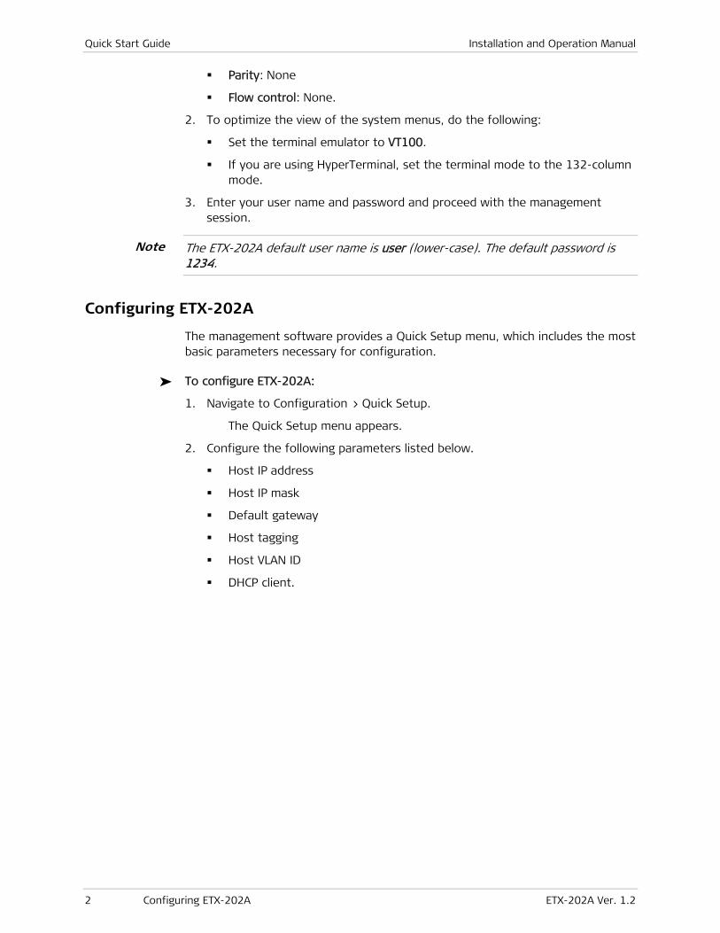
Parity: None
Flow control: None.
2. To optimize the view of the system menus, do the following:
Set the terminal emulator to VT100.
If you are using HyperTerminal, set the terminal mode to the 132-column mode.
3. Enter your user name and password and proceed with the management session.
The ETX-202A default user name is user (lower-case). The default password is 1234.
Configuring ETX-202A
The management software provides a Quick Setup menu, which includes the most basic parameters necessary for configuration.
To configure ETX-202A:
1. Navigate to Configuration > Quick Setup.
The Quick Setup menu appears.
2. Configure the following parameters listed below.
Host IP address
Host IP mask
Default gateway
Host tagging
Host VLAN ID
DHCP client.
Note

ETX-202A Ver. 1.2 i
Contents
Chapter 1. Introduction
1.1 Overview.................................................................................................................... 1-1 Device Options ....................................................................................................... 1-1 Applications ............................................................................................................ 1-2 Features ................................................................................................................. 1-2
Service Types ..................................................................................................... 1-2 Network Interface .............................................................................................. 1-3 User Interface .................................................................................................... 1-3 Link Redundancy ................................................................................................ 1-3 Traffic Mapping .................................................................................................. 1-3 Service Level Agreement (SLA) Monitoring .......................................................... 1-4 L2CP Handling .................................................................................................... 1-4 Fault Propagation ............................................................................................... 1-4 Management ...................................................................................................... 1-4 DHCP Client ........................................................................................................ 1-6 Statistics Collection ............................................................................................ 1-6 Dying Gasp ......................................................................................................... 1-6 Network Time Protocol ....................................................................................... 1-6 Diagnostic Tools ................................................................................................. 1-6
1.2 Physical Description ................................................................................................... 1-7 1.3 Functional Description ................................................................................................ 1-8
Traffic Flow ............................................................................................................ 1-8 Network Port .......................................................................................................... 1-9
Using Link Aggregation ....................................................................................... 1-9 Using 1:1 Bidirectional Redundancy .................................................................. 1-10
Fault Propagation ................................................................................................. 1-11 Diagnostic Loopbacks ........................................................................................... 1-11
1.4 Technical Specifications ............................................................................................ 1-12
Chapter 2. Installation and Setup
2.1 Site Requirements and Prerequisites .......................................................................... 2-1 2.2 Package Contents ...................................................................................................... 2-2 2.3 Mounting the Unit ...................................................................................................... 2-2 2.4 Installing SFP Modules ................................................................................................ 2-2 2.5 Connecting to the Ethernet Equipment ....................................................................... 2-3 2.6 Connecting to the ASCII Terminal ................................................................................ 2-4 2.7 Connecting to Power .................................................................................................. 2-5
Connecting AC Power .............................................................................................. 2-5 Connecting DC Power .............................................................................................. 2-5
Chapter 3. Operation
3.1 Turning On the Unit ................................................................................................... 3-1 3.2 Front Panel Indicators ................................................................................................ 3-2 3.3 Default Settings ......................................................................................................... 3-2 3.4 Configuration and Management Alternatives .............................................................. 3-9
Working with Terminal ............................................................................................ 3-9 Login ............................................................................................................... 3-11 Choosing Options ............................................................................................. 3-12

Table of Contents Installation and Operation Manual
ii ETX-202A Ver. 1.2
Ending a Terminal Configuration Session ........................................................... 3-13 Working with ConfiguRAD ..................................................................................... 3-14
Web Browser Requirements ............................................................................. 3-14 Login ............................................................................................................... 3-14 Navigating the ConfiguRAD Menus .................................................................... 3-15
Overview of Menu Operations ............................................................................... 3-16 3.5 Turning Off the Unit ................................................................................................. 3-19
Chapter 4. Configuration
4.1 Configuring ETX-202A for Management ...................................................................... 4-1 Configuring IP Host Parameters ............................................................................... 4-1
Configuring the DHCP Client ............................................................................... 4-2 Managing IP Parameters of the ETX-202A Host ................................................... 4-3
Entering Device Information .................................................................................... 4-3 Configuring ETX-202A Communities ........................................................................ 4-4 Configuring SNMPv3 ................................................................................................ 4-5
Enabling SNMPv3 ................................................................................................ 4-5 Adding SNMPv3 Users ........................................................................................ 4-6 Adding Notification Entries ................................................................................. 4-7 Assigning Traps .................................................................................................. 4-7 Configuring Target Parameters ........................................................................... 4-8 Configuring Target Address ................................................................................ 4-9 Mapping SNMPv1 to SNMPv3 ............................................................................ 4-10
Configuring the Host Encapsulation ....................................................................... 4-10 Configuring the Network Managers ....................................................................... 4-11 Controlling Management Access ............................................................................ 4-13
Defining the Access Policy ................................................................................ 4-15 Configuring Radius Server Parameters .............................................................. 4-15
Configuring Control Port Parameters ..................................................................... 4-17 Setting Scrolling Window Size ........................................................................... 4-18 Configuring Security Timeout ............................................................................ 4-18
4.2 Configuring ETX-202A for Operation ......................................................................... 4-18 Setting System Level Parameters .......................................................................... 4-19
Configuring the Link Protection ........................................................................ 4-19 Configuring Syslog ............................................................................................ 4-21
Configuring Physical Layer Parameters................................................................... 4-23 Configuring Network and User Ethernet Interfaces ............................................ 4-23 Configuring the Fault Propagation Wait-to-Restore Time ................................... 4-25
Configuring ETX-202A at the Application Level ...................................................... 4-25 Configuring the Quality of Service (QoS) ........................................................... 4-26 Configuring the OAM ........................................................................................ 4-32 Defining the Ethernet Flows ............................................................................. 4-42
4.3 Additional Tasks ....................................................................................................... 4-51 Displaying the ETX-202A Inventory ........................................................................ 4-51 Displaying the ETX-202A Status ............................................................................ 4-52
Displaying System Status Information ............................................................... 4-52 Displaying the Physical Layer Status ................................................................. 4-55
Displaying the Application Status .......................................................................... 4-56 Displaying the OAM Connection Status ............................................................. 4-56 Displaying the Link OAM Status ........................................................................ 4-56 Displaying the Data Flow Connection Status ..................................................... 4-58
Setting the Date and Time .................................................................................... 4-59 Receiving the Clock from the NTP ..................................................................... 4-59

Installation and Operation Manual Table of Contents
ETX-202A Ver. 1.2 iii
Configuring User Access ........................................................................................ 4-60 Transferring Software and Configuration Files ....................................................... 4-61 Swapping the Software Files ................................................................................. 4-63 Resetting ETX-202A .............................................................................................. 4-63
Resetting ETX-202A to the Defaults ................................................................. 4-63 Resetting ETX-202A ......................................................................................... 4-64
Chapter 5. Configuring Typical Applications
5.1 Configuring a Point-to-Point Application ..................................................................... 5-1 Configuring System Parameters ............................................................................... 5-2 Configuring Flow Interfaces ..................................................................................... 5-2 Configuring the Flows ............................................................................................. 5-4
Configuring Flows in ETX-202A (A) ..................................................................... 5-4 Configuring Flows in ETX-202A (B) ...................................................................... 5-9
Chapter 6. Troubleshooting and Diagnostics
6.1 Monitoring Performance ............................................................................................. 6-1 Displaying End-to-End Statistics .............................................................................. 6-1 Displaying Ethernet Status and Statistics ................................................................. 6-3
6.2 Handling Events and Traps ......................................................................................... 6-5 Displaying Events .................................................................................................... 6-5 Clearing Events ....................................................................................................... 6-7 Masking Alarm Traps ............................................................................................... 6-8
6.3 Testing ETX-202A ....................................................................................................... 6-8 Running a Ping Test ................................................................................................ 6-8 Tracing the Route ................................................................................................... 6-9 Running Loopbacks ............................................................................................... 6-10
6.4 Technical Support .................................................................................................... 6-14
Appendix A. Connector Wiring
Appendix B. Boot Manager
Appendix C. Operation, Administration, and Maintenance (OAM)

Table of Contents Installation and Operation Manual
iv ETX-202A Ver. 1.2
ETX-202A Ver. 1.2 Overview 1-1
Chapter 1
Introduction
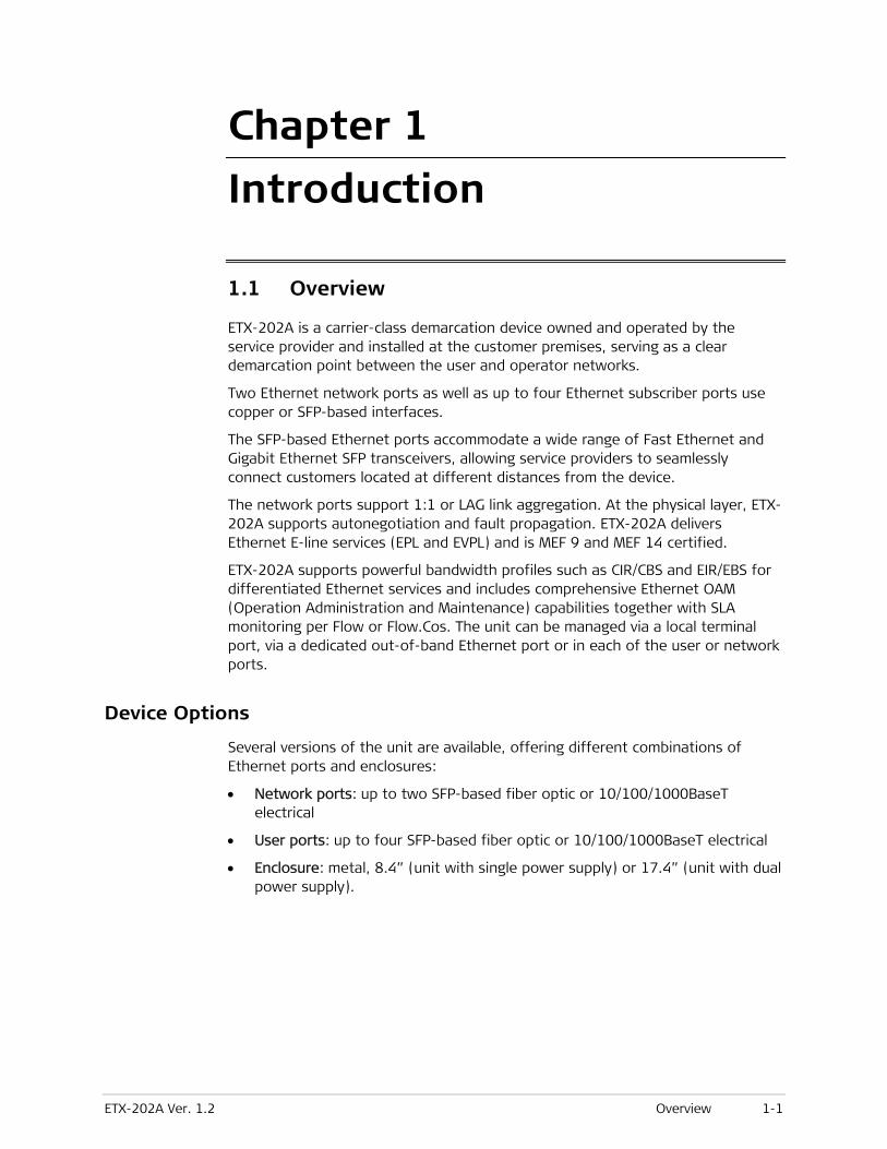
1.1 Overview
ETX-202A is a carrier-class demarcation device owned and operated by the service provider and installed at the customer premises, serving as a clear demarcation point between the user and operator networks.
Two Ethernet network ports as well as up to four Ethernet subscriber ports use copper or SFP-based interfaces.
The SFP-based Ethernet ports accommodate a wide range of Fast Ethernet and Gigabit Ethernet SFP transceivers, allowing service providers to seamlessly connect customers located at different distances from the device.
The network ports support 1:1 or LAG link aggregation. At the physical layer, ETX-202A supports autonegotiation and fault propagation. ETX-202A delivers Ethernet E-line services (EPL and EVPL) and is MEF 9 and MEF 14 certified.
ETX-202A supports powerful bandwidth profiles such as CIR/CBS and EIR/EBS for differentiated Ethernet services and includes comprehensive Ethernet OAM (Operation Administration and Maintenance) capabilities together with SLA monitoring per Flow or Flow.Cos. The unit can be managed via a local terminal port, via a dedicated out-of-band Ethernet port or in each of the user or network ports.
Device Options
Several versions of the unit are available, offering different combinations of Ethernet ports and enclosures:
• Network ports: up to two SFP-based fiber optic or 10/100/1000BaseT electrical
• User ports: up to four SFP-based fiber optic or 10/100/1000BaseT electrical
• Enclosure: metal, 8.4” (unit with single power supply) or 17.4” (unit with dual power supply).
Chapter 1 Introduction Installation and Operation Manual
1-2 Overview ETX-202A Ver. 1.2
Applications
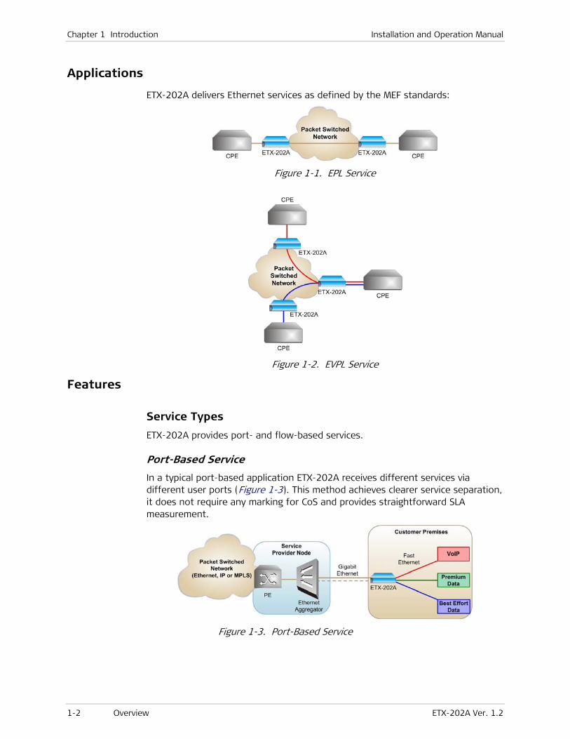
ETX-202A delivers Ethernet services as defined by the MEF standards:
Figure 1-1. EPL Service
Figure 1-2. EVPL Service
Features
Service Types
ETX-202A provides port- and flow-based services.
Port-Based Service
In a typical port-based application ETX-202A receives different services via different user ports (Figure 1-3). This method achieves clearer service separation, it does not require any marking for CoS and provides straightforward SLA measurement.
Figure 1-3. Port-Based Service

Installation and Operation Manual Chapter 1 Introduction
ETX-202A Ver. 1.2 Overview 1-3
Flow-Based Service
In a typical flow-based application different services are assigned to different Ethernet flows received by the same user port (Figure 1-4). This provides a cheaper, more scalable solution, with a possibility of mixing different service types.
Figure 1-4. Flow-Based Service
Network Interface
ETX-202A includes up to two Ethernet network ports. The network ports use industry-standard Gigabit or Fast Ethernet SFP (Small Form-Factor Pluggable) hot-swappable optical transceivers. ETX-202A can also be ordered with built-in 10/100/1000BaseT ports supporting autonegotiation and flow control.
User Interface
ETX-202A subscriber ports terminate in up to four built-in 10/100/1000BaseT ports or SFP-based fiber optic ports. The electrical ports support autonegotiation and flow control.
Link Redundancy
The unit supports network link redundancy in a LAG architecture. Dual homing technology in a 1:1 architecture allows ETX-202A to be connected to two different upstream devices.
Traffic Mapping
The ingress user traffic is mapped to the Ethernet flows (EVCs) using the following per-port criteria:
• Port-based (All-to-one bundling)
• User port + CE-VID
• User port + CE-VLAN priority
• User port + DSCP
• User port + ToS
• Network port + SP-VLAN
• Network port + SP-VLAN + SP-VLAN priority.
ETX-202A supports up to 30 Ethernet flows.

Chapter 1 Introduction Installation and Operation Manual
1-4 Overview ETX-202A Ver. 1.2
Services
Each flow can either have a single service assigned to it or up to eight services which are differentiated by SP-VLAN P-bits (flow.CoS),.
Policing and Bandwidth Profiles
Two policers (upstream and downstream) are applied per service. The policers operate according to the dual token bucket mechanism (CIR+CBS, EIR + EBS)
Traffic Prioritization and Quality of Service
Once traffic was classified to Flow or Flow.CoS, it can be mapped to SP (Strict Priority) queues or WFQ (Weighted Fair Queues). The section below explains both options.
• SP. The data flow set to the highest priority is transmitted first. If this data flow stops, all tasks at lower priorities move up by one priority level. For example, the data flow set to the second-highest priority is then transmitted at the highest priority.
• WFQ. Allows different scheduling priorities to statistically multiplex data flows with different shares on the service. Each data flow has a separate FIFO queue. A link transmitting at a data rate R, all non-empty data flows N are served simultaneously according to the assigned share w, each at an average rate of R/(w1 + w2 + w3 + … +wN). If one data flow stops, the remaining data flows each receive a larger share w.
The WRED mechanism ensures that queues are not congested and high priority traffic is maintained
Service Level Agreement (SLA) Monitoring
ETX-202A is an effective tool for measuring the Service Level Agreement parameters, such as Frame Delay, Frame Delay Variance (jitter), Frame Loss and Availability.
L2CP Handling
ETX-202A can be configured to tunnel the Layer-2 control frames across the network, to peer supported protocols (OAM.ah) or to discard the L2CP frames.
Fault Propagation
The unit provides the network-to-user fault propagation mechanism on the port level. When the fault propagation is enabled, the user port shuts itself down when a link failure is detected at the network port.
Management
Setup, monitoring and diagnostics tests can be performed using one of the following methods:
Note

Installation and Operation Manual Chapter 1 Introduction
ETX-202A Ver. 1.2 Overview 1-5
• Local management via ASCII terminal connected to the V.24/RS-232 DCE control port.
• Remote management via the network or user ports using Telnet SSH, Web, Secured Web (HTTPS) using ConfiguRAD, or RADview, RAD’s SNMP-based management system. ETX-202A supports the SNMP version 3 entity, providing secure access to the device by authenticating and encrypting packets transmitted over the network. ETX-202A can be managed as follows:
Remote inband management via one of the Ethernet ports using Telnet SSH, Web, Secured Web (HTTPs) or RADview, RAD’s SNMP based management system.
Local management via the last user port configured as a dedicated management port.
ConfiguRAD
ConfiguRAD is a user-friendly Web-based terminal management system serving for remote device configuration and maintenance. It is embedded into ETX-202A and provided at no extra cost. ConfiguRAD can be run from any standard Web browser.
Inband Management
ETX-202A can be managed via tagged or untagged management frames:
• When tagging is enabled, the host packets receive a VLAN tag, creating a dedicated management VLAN.
• When tagging is disabled, no traffic separation is performed and management packets can be forwarded to any user or network port.
Security
To ensure client-server communication privacy and correct user authentication, ETX-202A supports the security protocols listed below:
• RADIUS (client authentication only)
• SSL for Web-based management application
• SSH for Secure Shell communication session
• SNMPv3
Ethernet OAM
ETX-202A provides OAM to monitor and troubleshoot an Ethernet network and quickly detect failures. Two OAM types are provided:
• CFM OAM (End-to-end OAM) based on IEEE 802.1ag and Y.1731 for continuity check, non-intrusive loopback and performance management, including Frame Delay, Frame Delay Variation, Frame Loss, Availability etc
• EFM OAM (Link OAM) according to IEEE 802.3ah for remote management and fault indication, including remote loopback, dying gasp, and MIB parameters retrieval.
Appendix C provides a detailed description of the OAM functions.

Chapter 1 Introduction Installation and Operation Manual
1-6 Overview ETX-202A Ver. 1.2
Syslog Support
The syslog protocol is a client/server-type protocol, featuring a standard for forwarding log messages in an IP network. The syslog sender sends a small text message of less than 1024 bytes to the syslog receiver. Syslog messages can be sent via UDP and/or TCP in cleartext. However, although not part of the syslog protocol itself, an SSL wrapper such as Stunnel, sslio or sslwrap can be used to provide for a layer of encryption through SSL/TLS.
DHCP Client
When enabled, the DHCP client of ETX-202A requests an IP address, IP mask and default gateway from the DHCP server. In addition, ETX-202A defines a network manager with a valid IP address and subnet mask.
Statistics Collection
ETX-202A collects Ethernet performance statistics for the physical layers of the network/user ports, Ethernet flows and Flow.Cos.
Dying Gasp
ETX-202A units equipped with a single AC power supply feature a dying gasp mechanism. In case of a power outage, ETX-202A reports this failure to defined network management stations by sending out traps, thus enabling the unit to properly disconnect from the network.
Network Time Protocol
The Network Time Protocol (NTP) provides the means of synchronizing all managed elements across the network to a reliable clock source. ETX-202A supports the client side of the NTP v.3 (RFC 1305).
Diagnostic Tools
A built-in ping utility allows checking IP connectivity by pinging remote IP hosts.
The Trace Route application can quickly trace a route from ETX-202A to any other network device.
Physical loopbacks (remote/local on the port/flow level) can be closed on any of the ETX-202A ports. Layer-2 loopback with MAC address swapping enables end-to-end connectivity verification.

Installation and Operation Manual Chapter 1 Introduction
ETX-202A Ver. 1.2 Functional Description 1-7
1.2 Physical Description
Figure 1-5 shows a 3D view of ETX-202A units with 8.4-inch and 17.4-inch enclosures.
Figure 1-5. ETX-202A, 3D View
The front panel includes network and user Ethernet ports, and V.24 terminal connector. The ETX-202A interface connections are described in greater detail in Chapter 2. The AC/DC power connector is located on the rear panel of 8.4-inch units, and on the front panel of 17.4-inch units.
The front panel also includes several LED indicators, which display the status of power, Ethernet links, and alarms. For a detailed description of the LEDs, see Chapter 3.

Chapter 1 Introduction Installation and Operation Manual
1-8 Functional Description ETX-202A Ver. 1.2
1.3 Functional Description
Traffic Flow
Figure 1-6 illustrates the traffic handling process. Table 1-1 provides an overview of the traffic handling stages.
Figure 1-6. Traffic Handling Diagram
Table 1-1. Traffic Handling Stages
Processing Stage Description
Classification by Flow
Key per Port
Classifying traffic such as email traffic, content streaming,
large document transmission etc.
Policer per Flow Policing the entire traffic within the flow.
CoS/Services Dividing the services using a 3-bit field, specifying a priority
value between0 (signifying best-effort) and 7 (signifying
priority real-time data).
Policer per Service Policing each Class of Service (CoS).
Queues ‘Storing’ data that will be transmitted according to the CoS
level specified.
Rate
Limitation/Shaping
Ensuring that traffic is shaped to the desired rate.
Scheduling Scheduling and ‘regulating’ traffic
Editing and Marking Adding the SP-VLAN, swapping the CE-VLAN or neither, as well
as marking the priority on the outer VLAN header.

Installation and Operation Manual Chapter 1 Introduction
ETX-202A Ver. 1.2 Functional Description 1-9
Network Port
The two network interfaces operate redundant to each other, either as two separate links (1:1) or as a single logical link (LAG).
• 1:1 bidirectional protection (redundancy) mode. In this mode, only one port is active at a time to carry traffic. If it fails, the second port takes over. The recovery mode (revertive or non-revertive) and the restoration time in the revertive mode can be selected according to the application requirements.
• Link aggregation (LAG) mode according to IEEE 802.3ad (without LACP). In this mode, both ports receive traffic at the same time and one port transmits. If the transmitting port fails, traffic is transmitted and received over the second port. Both network ports must be enabled.
Using Link Aggregation
The two Gigabit Ethernet ports can be operated as a single logical interface, using link aggregation in accordance with IEEE 802.3ad without LACP (Link Aggregation Control Protocol). In the virtual link group only one link transmits at a time. If a failure occurs on the transmitting link, ETX-202A switches to the standby link in the group. The flip is performed by reassigning destination ports.
With link aggregation, the two GbE ports serve as a single logical interface. The two ports must be connected to the same switch/router, as shown in Figure 1-7.
Figure 1-7. Network Link Aggregation Redundancy Mode
Using link aggregation inherently provides redundancy, because that if one of the GbE ports fails, the other can continue transferring traffic. Therefore, link aggregation per IEEE 802.3ad has inherent APS (Automatic Protection Switching) characteristics.
Failure of one the links is detected by sensing the loss of valid signals at a port, in which case the whole traffic is sent through the remaining port. The switching time is less than a second.
Link aggregation always provides revertive recovery, because that as soon as the down port returns to normal, the full bandwidth is again available.
The equipment connected to the GbE ports must use compatible switching criteria for redundancy to be available:

Chapter 1 Introduction Installation and Operation Manual
1-10 Functional Description ETX-202A Ver. 1.2
• For networks using Layer 2 switching: the criterion is signal loss
• For networks using Layer 3 routing: the router must support IEEE 802.3ad or other link aggregation protocol that views the aggregated link as a single logical interface.
As the two GbE ports serve as a single logical interface, the learning tables do not change as a result of the interface flip.
Using 1:1 Bidirectional Redundancy As an alternative to link aggregation, the two ETX-202A network ports of one GbE module can be configured for 1:1 bidirectional mode. With this mode, two topologies can be used:
• Connection of both GbE ports to the same switch/router, as shown in Figure 1-7.
• Connection of the GbE ports to different switch/routers, as illustrated in Figure 1-8. The main advantage of this topology is its higher availability, because each port can be routed along a different path through the network. This topology is also referred to as dual homing.
Figure 1-8. 1:1 Bidirectional Redundancy Mode (Dual Homing)
With 1:1 bidirectional redundancy mode, at any time only one of the ports is actively carrying traffic, and the other port serves as the backup port. A RAD proprietary redundancy algorithm, based on loss of GbE signal, is used to detect line failure. The protection switching (flipping) time is less than 1 second. It also depends on the network “relearning“ time or aging.
The recovery mode after a protection switching can be selected in accordance with the application requirements:
• Non-revertive mode –ETX-202A will not automatically flip back after the failed port returns to normal operation, but only when the currently used port fails, or after a manual flip command.
• Revertive mode –ETX-202A will flip back to the original port when it returns to normal operation. Flipping back can be delayed by specifying a restoration time, during which alarms are ignored. As a result, ETX-202A starts evaluating the criteria for protection switching (flipping) only after the restoration time expires, thereby ensuring that another flip cannot occur before the specified time expires.

Installation and Operation Manual Chapter 1 Introduction
ETX-202A Ver. 1.2 Functional Description 1-11
Fault Propagation
If a network link fails, ETX-202A propagates this condition to some or all Fault-Propagation-enabled user ports as illustrated in Figure 1-9. Doing so, the user port shuts down, thus signaling the connected CPE to stop forwarding frames through this port.
Figure 1-9. Fault Propagation
Diagnostic Loopbacks
ETX-202A supports the following diagnostics loopbacks:
• Layer-1 loopback performed at the PHY of the physical ports. When the loopback is active the data forwarded to a bridge port is looped from the Tx path to the Rx path, disrupting the traffic. This loopback cannot pass through Ethernet bridges.
• Layer-2 loopback with MAC address swapping, when ETX-202A exchanges source and destination MAC addresses of the incoming packets. This loopback can be performed per VLAN (or EVC) once it passes through Ethernet bridges and does not disrupt traffic flows, which are not being tested.
Chapter 1 Introduction Installation and Operation Manual
1-12 Technical Specifications ETX-202A Ver. 1.2
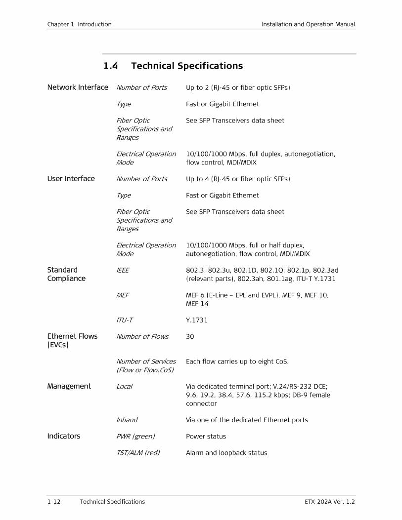
1.4 Technical Specifications
Network Interface Number of Ports Up to 2 (RJ-45 or fiber optic SFPs)
Type Fast or Gigabit Ethernet
Fiber Optic Specifications and Ranges
See SFP Transceivers data sheet
Electrical Operation Mode
10/100/1000 Mbps, full duplex, autonegotiation, flow control, MDI/MDIX
User Interface Number of Ports Up to 4 (RJ-45 or fiber optic SFPs)
Type Fast or Gigabit Ethernet
Fiber Optic Specifications and Ranges
See SFP Transceivers data sheet
Electrical Operation Mode
10/100/1000 Mbps, full or half duplex, autonegotiation, flow control, MDI/MDIX
Standard Compliance
IEEE 802.3, 802.3u, 802.1D, 802.1Q, 802.1p, 802.3ad (relevant parts), 802.3ah, 801.1ag, ITU-T Y.1731
MEF MEF 6 (E-Line – EPL and EVPL), MEF 9, MEF 10, MEF 14
ITU-T Y.1731
Ethernet Flows (EVCs)
Number of Flows 30
Number of Services (Flow or Flow.CoS)
Each flow carries up to eight CoS.
Management Local Via dedicated terminal port; V.24/RS-232 DCE; 9.6, 19.2, 38.4, 57.6, 115.2 kbps; DB-9 female connector
Inband Via one of the dedicated Ethernet ports
Indicators PWR (green) Power status
TST/ALM (red) Alarm and loopback status

Installation and Operation Manual Chapter 1 Introduction
ETX-202A Ver. 1.2 Technical Specifications 1-13
NET 1, NET 2, USER 3–6 (green)
Link/activity status of the network/user port
Power AC 100–240 VAC, 50/60 Hz
Wide-range DC 24/48V (20–72 VDC)
Power Consumption 18.5W max
Physical (single power supply)
Height 43.7 mm (1.7 in)
Width 215 mm (8.4 in)
Depth 300 mm (11.8 in)
Weight 2.4 kg (5.2 lb)
Physical (dual power supply)
Height 43.7 mm (1.7 in)
Width 440 mm (17.4 in)
Depth 240 mm (9.5 in)
Weight 3.1 kg (6.8 lb)
Environment Temperature ETX-202A: 0°C to 50°C (32°C to 122°F)
ETX-202A/H: -40 to 65°C (-22 to 149°F)
Humidity Up to 90%, non-condensing

Chapter 1 Introduction Installation and Operation Manual
1-14 Technical Specifications ETX-202A Ver. 1.2

ETX-202A Ver. 1.2 Site Requirements and Prerequisites 2-1
Chapter 2
Installation and Setup This chapter describes installation and setup procedures for the ETX-202A unit.
After installing the unit, refer to Chapter 3 for the operating instructions.
If a problem is encountered, refer to Chapter 6 for test and diagnostic instructions.
Internal settings, adjustment, maintenance, and repairs may be performed only by a skilled technician who is aware of the hazards involved.
Always observe standard safety precautions during installation, operation, and maintenance of this product.
2.1 Site Requirements and Prerequisites
The ETX-202A device is intended for installation on desktops, 19” racks, and walls. The following mounting kits are available from RAD:
• RM-35 for mounting one or two 8.4” ETX-202A units in a 19” rack
• RM-34 for mounting one 17.4” ETX-202A unit in a 19” rack
• WM-35 for mounting one 8.4” ETX-202A unit on a wall
• WM-34 for mounting one 17.4” ETX-202A unit on a wall.
AC-powered ETX-202A units should be installed within 1.5m (5 ft) of an easily-accessible grounded AC outlet capable of furnishing the voltage in accordance with ETX-202A nominal supply voltage.
DC-powered ETX-202A units require a -48 VDC power source, which must be adequately isolated from the main supply.
Refer also to the sections describing connections of AC and DC mains at the beginning of the manual.
Allow at least 90 cm (36 in) of frontal clearance for operating and maintenance accessibility. Allow at least 10 cm (4 in) clearance at the rear of the unit for signal lines and interface cables.
The ambient operating temperature of ETX-202A is 0 to 50°C (32 to 122°F), at a relative humidity of up to 90%, non-condensing.
Warning
Note
Chapter 2 Installation and Setup Installation and Operation Manual
2-2 Installing SFP Modules ETX-202A Ver. 1.2
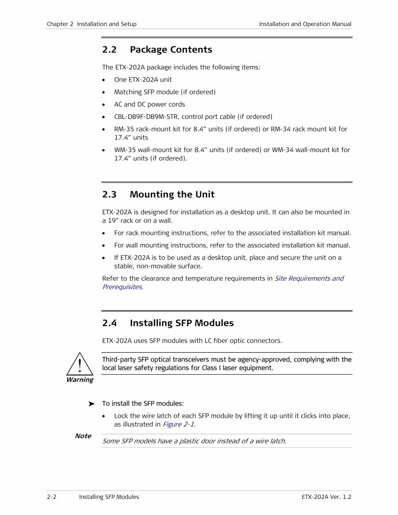
2.2 Package Contents
The ETX-202A package includes the following items:
• One ETX-202A unit
• Matching SFP module (if ordered)
• AC and DC power cords
• CBL-DB9F-DB9M-STR, control port cable (if ordered)
• RM-35 rack-mount kit for 8.4” units (if ordered) or RM-34 rack mount kit for 17.4” units
• WM-35 wall-mount kit for 8.4” units (if ordered) or WM-34 wall-mount kit for 17.4” units (if ordered).
2.3 Mounting the Unit
ETX-202A is designed for installation as a desktop unit. It can also be mounted in a 19" rack or on a wall.
• For rack mounting instructions, refer to the associated installation kit manual.
• For wall mounting instructions, refer to the associated installation kit manual.
• If ETX-202A is to be used as a desktop unit, place and secure the unit on a stable, non-movable surface.
Refer to the clearance and temperature requirements in Site Requirements and Prerequisites.
2.4 Installing SFP Modules
ETX-202A uses SFP modules with LC fiber optic connectors.
Third-party SFP optical transceivers must be agency-approved, complying with the local laser safety regulations for Class I laser equipment.
To install the SFP modules:
• Lock the wire latch of each SFP module by lifting it up until it clicks into place, as illustrated in Figure 2-1.
Some SFP models have a plastic door instead of a wire latch.
Note
Warning

Installation and Operation Manual Chapter 2 Installation and Setup
ETX-202A Ver. 1.2 Connecting to the Ethernet Equipment 2-3
Figure 2-1. Locking the SFP Wire Latch
1. Carefully remove the dust covers from the SFP slot.
2. Insert the rear end of SFP into the socket, and push slowly backwards to mate the connectors until the SFP clicks into place. If you feel resistance before the connectors are fully mated, retract the SFP using the wire latch as a pulling handle, and then repeat the procedure.
3. Remove the protective rubber caps from the SFP modules.
To remove the SFP module:
1. Disconnect the fiber optic cables from the SFP module.
2. Unlock the wire latch by lowering it downwards (as opposed to locking).
3. Hold the wire latch and pull the SFP module out of the Ethernet port.
2.5 Connecting to the Ethernet Equipment
ETX-202A is connected to the Ethernet equipment via the fiber optic LC designated GbE or 8-pin RJ-45 electrical port designated 10/100/1000BT. Refer to Appendix A for the RJ-45 connector pinout. The instructions below are illustrated using a sample configuration with regular (8.4”) enclosure.
To connect to the Ethernet equipment with fiber optic interface:
• Connect ETX-202A to the Ethernet equipment using a standard fiber optic cable terminated with an LC connector.
LINK/ACTLINK/ACT
1
4 5 6 PWR
2 3TST/ALM
ETX-202A
4 5 63USERNET
1NET
2
GbE GbE 10/100/1000BT
MNG-ETH
10/100/1000BT 10/100/1000BT 10/100/1000BTDCE
CONTROL
Figure 2-2. GbE Fiber Optic Connectors

Chapter 2 Installation and Setup Installation and Operation Manual
2-4 Connecting to the ASCII Terminal ETX-202A Ver. 1.2
To connect to the Ethernet equipment with a copper interface:
• Connect ETX-202A to the Ethernet network equipment using a standard straight UTP cable terminated with an RJ-45 connector.
In order to comply with electromagnetic compatibility requirements (Class B), it is recommended to use shielded cables when connecting to the RJ-45 port of the ETX-202A electrical network or user interface.
LINK/ACTLINK/ACT
1
4 5 6 PWR
2 3TST/ALM
ETX-202A
4 5 63USERNET
1NET
2
GbE GbE 10/100/1000BT
MNG-ETH
10/100/1000BT 10/100/1000BT 10/100/1000BTDCE
CONTROL
Figure 2-3. 10/10/1000BT Electrical Connectors
2.6 Connecting to the ASCII Terminal
ETX-202A is connected to an ASCII terminal via a 9-pin D-type female connector designated CONTROL. Refer to Appendix A for the connector pinout.
LINK/ACTLINK/ACT
1
4 5 6 PWR
2 3TST/ALM
ETX-202A
4 5 63USERNET
1NET
2
GbE GbE 10/100/1000BT
MNG-ETH
10/100/1000BT 10/100/1000BT 10/100/1000BTDCE
CONTROL
Figure 2-4. CONTROL Connector
Terminal cables must have a frame ground connection. Use ungrounded cables when connecting a supervisory terminal to a DC-powered unit with floating ground. Using improper terminal cable may result in damage to the supervisory terminal port.
To connect to an ASCII terminal:
1. Connect the male 9-pin D-type connector of CBL-DB9F-DB9M-STR straight cable available from RAD to the CONTROL connector.
2. Connect the other end of the CBL-DB9F-DB9M-STR cable to an ASCII terminal.
Note
Caution

Installation and Operation Manual Chapter 2 Installation and Setup
ETX-202A Ver. 1.2 Connecting to Power 2-5
2.7 Connecting to Power
Regular units are available with AC or WRDC power supply. For the exact specificationss, refer to Technical Specifications in Chapter 1.
Before connecting or disconnecting any cable, the protective earth terminals of this unit must be connected to the protective ground conductor of the mains (AC or DC) power cord. If you are using an extension cord (power cable) make sure it is grounded as well.
Any interruption of the protective (grounding) conductor (inside or outside the instrument) or disconnecting of the protective earth terminal can make this unit dangerous. Intentional interruption is prohibited.
Refer also to the sections describing connections of AC and DC power at the beginning of the manual.
Connecting AC Power
AC power should be supplied via a 1.5m (5 ft) standard power cable terminated by a standard 3-prong socket. A cable is provided with the unit.
To connect AC power:
1. Connect the power cable to the power connector on the ETX-202A rear panel.
2. Connect the power cable to the mains outlet.
The unit turns on automatically once connected to the mains.
Connecting DC Power
Terminal block connectors with adapters are available for DC power supplies.
To connect DC power:
• Refer to the Terminal Block Connector DC Power Supply Connection supplement for instructions on wiring the DC adapters. This supplement can be found at the end of this manual.
The power connectors of 8.4” units are located at the rear while the power connectors of 17.4” units are located at the front.
Warning
Note
Note

Chapter 2 Installation and Setup Installation and Operation Manual
2-6 Connecting to Power ETX-202A Ver. 1.2

ETX-202A Ver. 1.2 Turning On the Unit 3-1
Chapter 3
Operation This chapter:
• Explains power-on and power-off procedures
• Provides a detailed description of the front panel controls and indicators and their functions
• Lists alternative methods of the product configuration, explaining ASCII terminal and Web browser management applications and illustrating management menus.
For a detailed explanation of parameters in the menus, see Chapter 4.
3.1 Turning On the Unit
To turn on ETX-202A:
• Connect the power cord to the mains.
The PWR indicator lights up and remains lit as long as ETX-202A receives power.
ETX-202A requires no operator attention once installed, with the exception of occasional monitoring of front panel indicators. Intervention is only required when ETX-202A must be configured to its operational requirements, or diagnostic tests are performed.

Chapter 3 Operation Installation and Operation Manual
3-2 Default Settings ETX-202A Ver. 1.2
3.2 Front Panel Indicators
The unit's LEDs are located on the front panel (see Figure 3-1). Table 3-1 lists the functions of the ETX-202A LED indicators.
LINK/ACTLINK/ACT
1
4 5 6 PWR
2 3TST/ALM
ETX-202A
4 5 63USERNET
1NET
2
GbE GbE 10/100/1000BT
MNG-ETH
10/100/1000BT 10/100/1000BT 10/100/1000BTDCE
CONTROL
Figure 3-1. ETX-202A Front Panel
Table 3-1. ETX-202A LEDs and Controls
Name Type Function
PWR Green LED ON – Power is ON
Name Type Function
TST/ALM Red LED ON – One of the Ethernet links is down
Blinking – Diagnostic loopback is active
LINK/ACT
1, 2, 3, 4, 5, 6
Green LEDs ON – Corresponding Ethernet link is OK
Blinks – Data is being transmitted or received on the corresponding Ethernet
link
The number of network ports and user ports and the corresponding number of LEDs depend on the hardware configuration provided.
3.3 Default Settings
Table 3-2 lists the default settings of the ETX-202A configuration parameters.
Table 3-2. Default Settings
Type Parameter Default Value
Quick Setup Host IP Address 0.0.0.0
Host IP Mask 0.0.0.0
Default Gateway 0.0.0.0
Host Tagging Tagged
Host VLAN ID 300
DHCP Client Enable
Note

Installation and Operation Manual Chapter 3 Operation
ETX-202A Ver. 1.2 Default Settings 3-3
Type Parameter Default Value
System
Host IP Address 0.0.0.0
IP Mask 0.0.0.0
Default Gateway 0.0.0.0
DHCP Enable
Default IP 0.0.0.0
DHCP Status Server ID The DHCP server’s IP
address
Lease Expiration Time The time when the
lease expires
Current Status Trying to locate
available server
Management
Device Info Name ETX-202A
Location The location of the
device
Contact Person Name of contact person
SNMPv3 SNMPv3 Disabled
Host Read Community Public
Write Community Private
Trap Community Public
Encapsulation Host Tagging Tagged
Management Classification VLAN ID
Host VLAN ID 300
Host VLAN Priority 7
Security Definition Network Only

Chapter 3 Operation Installation and Operation Manual
3-4 Default Settings ETX-202A Ver. 1.2
Type Parameter Default Value
Management Access
User Access User Name su
Access All
‘su’ Password --
New Password --
Confirm New Password --
Telnet/SSH Access Enable
SNMP Access Disable
Web Access Enable
Access Policy 1st level – Local
RADIUS Parameters Server Access Disable
Server IP Address 0.0.0.0
Number of Retries 2
Timeout (in seconds) 2
Authentication Port 1812
Accounting Port 1813
Alarm Trap Mask Alarm ID 1
Trap Status Masked
Traps Delay Traps Delay 0
Control Port Baud rate (bps) 115200
Set Scrolling Window Size 4
Security Timeout (min.) 10
Date/Time Time 00:00:00
Date 2008-01-01
NTP Mode Disable
Protection Redundancy Method LAG
Redundancy Method (LAG) Wait to Restore 0
Redundancy Method (1:1) Recovery Mode Revertive
Wait to Restore 0
Shut Down Duration Upon
Flip
0
Set Active Port None

Installation and Operation Manual Chapter 3 Operation
ETX-202A Ver. 1.2 Default Settings 3-5
Type Parameter Default Value
Syslog Device Logging Status Disable
Device UDP Port 514
Facility Local 1
Severity Level Minor
Server Parameters Server IP Address 0.0.0.0
Server UDP Port 514
Physical Layers
Ethernet Administrative Status Up
User Name Network 1
Autonegotiation Enable
Max Capability Advertised 1000baseX Full Duplex
OAM (802.3ah) Disable
Fault Propagation WTR Fault Propagation WTR 0
Application
Flows
Flow Interface (Network ports) Flow Key SP-VLAN-ID
CoS Profile UserCosPbits
SP Tag Protocol Identifier 8100
Default IP Precedence 0
Egress MTU 1790
L2CP Handling Tunnel
Queue Group Profile Default Scheduler
Flow Interface (User Port) Accept Frame Type
(only user ports)
All
Flow Key CE-VLAN ID
CoS Profile UsersCosPbits
Untagged Frames Handling Add CE-VLAN Tag
Default VID 1
Default 802.1p 0
Egress MTU 1790
L2CP Handling Tunnel
Marking Profile Marking1
Queue Group Profile Default Scheduler

Chapter 3 Operation Installation and Operation Manual
3-6 Default Settings ETX-202A Ver. 1.2
Type Parameter Default Value
Flow Definition
Flow Interface List SP Tag Handling Stack
SB VLAN 0
QoS
CoS Profiles CoS Profile Name UsersCosPbits
CoS Mapping Tag Value 0 0
Tag Value 1 0
Tag Value 2 0
Tag Value 3 0
Tag Value 4 0
Tag Value 5 0
Tag Value 6 0
Tag Value 7 0
Marking Profiles Profile Name Marking1
Marking CoS Value 0 0
CoS Value 1 0
CoS Value 2 0
CoS Value 3 0
CoS Value 4 0
CoS Value 5 0
CoS Value 6 0
CoS Value 7 0
Bandwidth Profiles Profile Name Profile1
CIR 0
CBS 0
EIR 100,0000
EBS 32,767
Policed Traffic All
Color Mode Blind
Coupling Flag Disable
Queue Profiles Profile ID 1
Profile Name DefaultQueue1

Installation and Operation Manual Chapter 3 Operation
ETX-202A Ver. 1.2 Default Settings 3-7
Type Parameter Default Value
Internal Queues
Scheduling WFQ
Weight 3
Queues Length 10000
OAM ID Put your string here
End-to-End Standard OAM MAC
Address
01-80-C2-00-00-30
Standard OAM EtherType 8902
MD Names MD Format String
MD Name None
Flows Flow Name Put your string here
SP VLAN 0
Protocol Type Standard
MAID MD ID 1
MD Format None
MD Name None
MA Format String
MA Name DEFAULT
MEP Local ID 0
OAM Destination Address
Type
Mulicast
Remote ID 0
MD Level 3
OAM Mode Disable
CC Interval 1 second
Services Performance Monitoring Disabled
Priority 0
Delay Objective 1
Delay Variation Objective 1
Event Report Event Reporting Type None
Frame Loss Ratio Event Reporting None
Rising Threshold 1E-10
Falling Threshold 1E-10
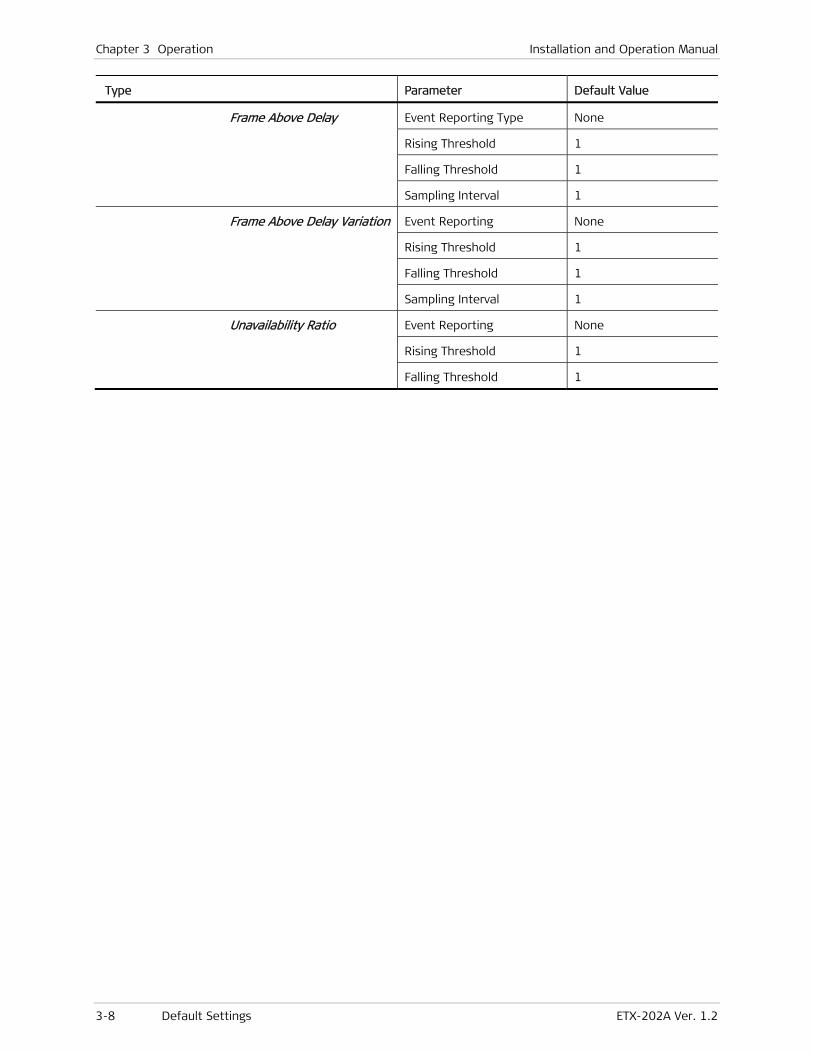
Chapter 3 Operation Installation and Operation Manual
3-8 Default Settings ETX-202A Ver. 1.2
Type Parameter Default Value
Frame Above Delay Event Reporting Type None
Rising Threshold 1
Falling Threshold 1
Sampling Interval 1
Frame Above Delay Variation Event Reporting None
Rising Threshold 1
Falling Threshold 1
Sampling Interval 1
Unavailability Ratio Event Reporting None
Rising Threshold 1
Falling Threshold 1

Installation and Operation Manual Chapter 3 Operation
ETX-202A Ver. 1.2 Configuration and Management Alternatives 3-9
3.4 Configuration and Management Alternatives
Once installed, there are no special operating procedures for ETX-202A. The unit operates automatically after it has started up. The unit’s operational status can be constantly monitored.
If required, ETX-202A can be reconfigured. ETX-202A can be managed using different ports and applications:
• Local management via an ASCII terminal connected to the RS-232 port. Usually, preliminary configuration of the system parameters is performed via ASCII terminal. Once the ETX-202A host IP parameters are set, it is possible to access it via Telnet SSH, ConfiguRAD, SSL, or SNMP for further configuration.
• Remote inband management via user or the network ports or out-of-band via the out-of-band port. Remote management via Telnet, ConfiguRAD (RAD’s Web-based application), or SNMP. Alternatively, you may manage ETX-202A via a third-party SNMP-based NMS. Refer to Chapter 6 for a trap list.
The following functions are supported by the ETX-202A management software:
• Viewing system information
• Modifying configuration and mode of operation, including setting system default values and resetting the unit
• Monitoring ETX-202A performance
• Initiating connectivity tests
• Uploading and downloading software and configuration files.
Working with Terminal
ETX-202A has a V.24/RS-232 asynchronous DCE port, designated CONTROL and terminated in a 9-pin D-type female connector. The control port continuously monitors the incoming data stream and immediately responds to any input string received through this port.
The ETX-202A control port can be configured to communicate at the following rates: 9.6, 19.2, 38.4, 57.6 or 115.2 kbps.

Chapter 3 Operation Installation and Operation Manual
3-10 Configuration and Management Alternatives ETX-202A Ver. 1.2
To start a terminal control session:
1. Make sure all ETX-202A cables and connectors are properly connected.
2. Connect ETX-202A to a PC equipped with an ASCII terminal emulation application (for example, Windows HyperTerminal or Procomm).
3. Turn on the control terminal PC and set its port parameters to the following:
Bits per second: 115,200
Data bits: 8
Parity: None
Stop bits: 1
Flow control: None.
4. Set the terminal emulator to ANSI VT100 emulation (for optimal view of system menus).
5. When the unit has initialized and successfully passed the self-test, press any key to display the user name and password entry fields.

Installation and Operation Manual Chapter 3 Operation
ETX-202A Ver. 1.2 Configuration and Management Alternatives 3-11
Login
To prevent unauthorized modification of the operating parameters, ETX-202A supports two access levels:
• Superuser can perform all the activities supported by the ETX-202A management facility, including defining new users.
• User’s access rights (full control or read only) are defined by the superuser. Users are not allowed to create new users.
It is recommended to change default passwords to prevent unauthorized access to the unit.
To enter as Superuser:
1. Enter su as user name and press <Enter>.
2. Enter 1234 as password and press <Enter>.
The Main menu appears.
Superuser allows you to configure all parameters of ETX-202A and to change the su and user passwords.
To enter as User:
1. Enter user as user name and press <Enter>.
2. Enter 1234 as password and press <Enter>.
The Main menu appears.
• If you enter an invalid password in three consecutive attempts, the system becomes inaccessible for 15 minutes.
• Unnumbered menu items are inaccessible for editing.
Note
Note

Chapter 3 Operation Installation and Operation Manual
3-12 Configuration and Management Alternatives ETX-202A Ver. 1.2
Choosing Options
How to use the terminal to perform a desired activity:
• To select a menu item, type the corresponding line number and then press <Enter>. This will either …
… display a submenu or a parameter selection screen …
or …
… let you type the (free text) parameter value in the same row
or …
… toggle the current value of the corresponding parameter (relevant to ENABLE/DISABLE or ON/OFF selections).
• The type of response to be expected after selecting a menu item is indicated as follows:
> Selecting that item will display a submenu or a parameter selection screen.
... Selecting that item will let you type the desired value in the same line.
Nothing When neither symbol is displayed, selecting that item will toggle the current selection, now shown in brackets (for example, this will change ENABLE to DISABLE or vice versa).
• When a menu does not fit on one screen (because it includes many lines), it is displayed on two consecutive pages. In this case, you will see …(N) after the last line on the first page and …(P) after the last line on the second page:
While on the first page, press <N> to display the second page
While on the second page, press <P> to return to the first page.

Installation and Operation Manual Chapter 3 Operation
ETX-202A Ver. 1.2 Configuration and Management Alternatives 3-13
• When a configuration screen is organized as a table, a special set of keys is used for navigation within the table (such screens always have a ? (help) option that displays these keys). The following keys may be used for navigation within tables:
L – move to the left R – move to the right
^D – scroll down ^U – scroll up
In addition, the following shortcuts are also available:
Tab – select the next cell that may be changed
G followed by <row number>,<col number> – select a specific cell. For example, type G2,5 to select the fifth cell in the second row.
• The current value of a parameter is listed within parentheses ( ). To change a parameter value on a parameter selection screen:
Type the line number corresponding to the desired value, and then press <Enter>.
To enter a value which requires free text entry, type in the desired string and then press <Enter>. Use backspace to erase the current string.
Note that whenever applicable, the allowed range of values of a parameter is listed within square brackets [ ].
• The entry is checked after pressing <Enter>, and it is accepted only if it is valid:
If you make an error, for example, if you press a key not active on the current screen or select an invalid parameter value, an ERROR indicator appears in the right-hand corner. This indicator disappears as soon as you make a correct operation.
If you select a parameter value incompatible with the current operating state or other parameters, you will see a message that explains the error.
• When done with the current screen, press <Esc> to return to the previous screen, or press <!> to return directly to the main menu.
Ending a Terminal Configuration Session
To end the current terminal session:
• Press <&>.
After a session is ended, it is necessary to enter again a valid user name and password to start a new session.

Chapter 3 Operation Installation and Operation Manual
3-14 Configuration and Management Alternatives ETX-202A Ver. 1.2
Working with ConfiguRAD
This section instructs you on managing ETX-202A using a web-based interface.
Web Browser Requirements
The following Web browsers can be used to access the ETX-202A supervision utility from any location that enables access to the ETX-202A using Internet protocols.
• Internet Explorer 6.0 and up, running on Windows™
• Netscape Communicator 7.0 and up, running on Windows™, HPOV or Linux
• Firefox 1.0.4 and up, running on Windows™
• Mozilla 1.4.3 and up, running on Linux.
However, before using Web access, it is necessary to perform a preliminary configuration of ETX-202A.
When using a Web browser, pay attention to the following points:
• Enable scripts
• Configure the firewall that is probably installed on your PC in order to allow access to the destination IP address
• Disable pop-up blocking software (such as Google Popup Blocker); you may also have to configure your spyware/adware protection program to accept traffic from/to the destination IP address
• Browsers store the last viewed pages in a special cache. To prevent configuration errors, it is absolutely necessary to flush the browser’s cache whenever you return to the same screen.
Login
To manage ETX-202A via Web browser:
1. Open the Web browser.
2. Enter the IP address of ETX-202A in the address field of the browser in the following format: http://’IP address’ (‘IP address’ stands for the actual ETX-202A IP address).
3. After entering the address, press <Enter> to command the browser to connect.
4. After the opening window is displayed, click LOGIN.
5. In the Password Entry window, log in by entering the user name (user) and the password (1234).
The Main menu is appears.
6. Use standard browser operating procedures to perform the desired activities.

Installation and Operation Manual Chapter 3 Operation
ETX-202A Ver. 1.2 Configuration and Management Alternatives 3-15
• It is recommended to change default passwords to prevent unauthorized access to the unit.
• ETX-202A allows up to three management sessions to be active at a time. This includes up to two network sessions (Telnet, SNMP) and one ASCII terminal session.
• If no user input is detected for 5 minutes during ConfiguRAD session, ETX-202A automatically disconnects from the management station.
Navigating the ConfiguRAD Menus
ConfiguRAD is a Web-based remote access terminal management software. It provides a user-friendly interface for configuring, collecting statistics and performing diagnostic tests on the ETX-202A units.
To choose an option:
1. Click a link in the ConfiguRAD screen to display the next menu.
2. Once the target screen is displayed, select a value from the drop-down box or enter it in a text box.
At the left-hand bottom corner ConfiguRAD provides some auxiliary management tools:
• Status. shows the number of users currently managing ETX-202A
• Trace. Opens an additional pane for system messages, progress indicators (ping, software and configuration file downloads) and alarms. It is recommended to keep the trace pane open all the time.
• Refresh All. Refreshes all ConfiguRAD display elements.
Notes

Chapter 3 Operation Installation and Operation Manual
3-16 Configuration and Management Alternatives ETX-202A Ver. 1.2
Overview of Menu Operations
Use these menu trees as a reference aid while performing configuration and control functions. Chapter 4 illustrates menus and explains parameters. Table 3-2 lists default values.
Host IP AddressHost IP MaskDefault GatewayHost TaggingHost VLAN IDDHCP Client
Main Menu Configuration Quick SetupInventory Configuration Monitoring Diagnostics Utilities
Quick SetupSystemPhysical Layers Application
Figure 3-2. Main Menu > Configuration > Quick Setup
Host Management Control Port Date/Time Factory DefaultProtectionSyslog
IP Ad dressIP MaskDefa ult Gateway
Defa ult IPDHCP Status
DHCP
(if DHSCP en abled)
Device InfoSNMPv3
Host Manager ListManagement Access Alarm Trap MaskTraps Delay
SNMPv3 Settings
Baud RateSet Scrolling Window SizeSecurity Timeout
Redundancy MethodRecovery Mode (1:1 only)Wait to RestoreShut Down Duration Upon Flip
(1:1 only)Set Active Port (1:1 only)
Name Location Contact Person
Read Community Write Community Trap CommunityEncapsulation
User Access Telnet/SSH Access SNMP Access Web AccessAccess Policy
RADI US Parameters
Alarm IDTrap Status
User Name Access 'su' Password New Password Confirm New Password
Host TaggingManagement ClassificationHost VLAN IDMarking Host VLAN PrioritySecu rity Definition
Configuration SystemHost
Management
Control Port
Protection
Device Info
Host
Management Access (RADIUS Enabled)
Alarm Trap Mask
User Access
Encapsulation (Host Tagging set to Tag ged)
Quick SetupSystemPhysical Layers Application
UsersTargets & NotifySNMPv1/v3 MappingSNMPv3 Factory DefaultsSummary User TableSummary Target Table
Server AccessServer IP AddressKey StringNumber of RetriesTimeoutAuthentication PortAccounting Port
1st Level2nd Level
Security NameAuthentication ProtocolAuthentication PasswordPrivacy ProtocolPrivacy Password
Target ParamsTarget AddressNotifyTrap
NameMessage Processing ModelSecurity ModelSecurity NameSecurity Level
NameIP AddressParams NameAddress MaskTag List
NameTag
Trap NameNotify Name
SNMPv3 Settings (SNMPv3 Ena bled)
RADIUS Parameters(RADIUS Enabled)
Access Policy
Users
Target s and Notify
Target Params
Target Address
Notify
Trap
Device Logging StatusDevice UDP PortFacilitySeverity LevelServer Parameters
Syslog
TimeDateNTP ModeNTP Server IP AddressGMTNTP Update Interval
Date/Time (NTP Enabled)
Unicast ClientDisable
NTP Mode
(SNMPv3 Disabled)
Encapsulation
Host (SNMPv 3 Enabled)
OR
OR Host TaggingSecurity Definition
Enca psulation (Host Tagging s et to Unta gged)
Server IP Add ress
Server UDP Port
Server Parameters
Figure 3-3. Configuration > System
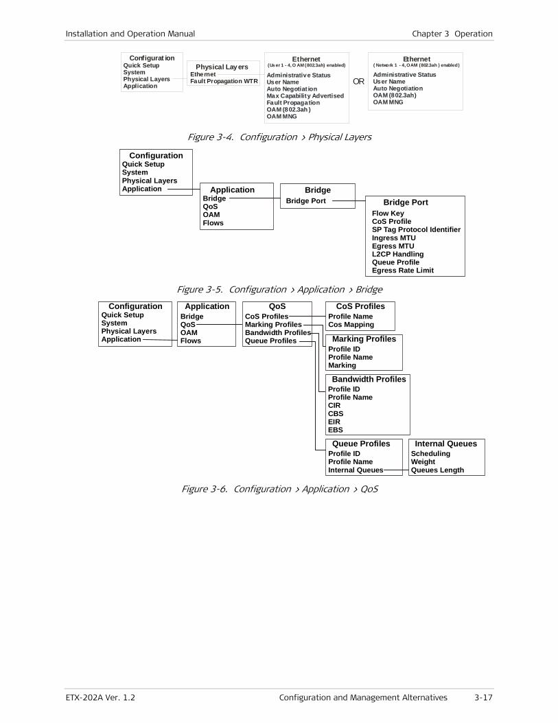
Installation and Operation Manual Chapter 3 Operation
ETX-202A Ver. 1.2 Configuration and Management Alternatives 3-17
Administrative StatusUser NameAuto Negotiat ionMax Capability AdvertisedFault PropagationOAM (802.3ah )OAM MNG
Configurat ionPhysical Lay ers
Ethernet(Us er 1 - 4, ) O AM (802.3ah) enabledQuick Setup
SystemPhysical Layers Application
EthernetFault Propagation WTR OR
Administrative StatusUser NameAuto NegotiationOAM
(802.3ah)OAM MNG
Ethernet ( Network 1 - 4, OAM (802.3ah ) enabled)
Figure 3-4. Configuration > Physical Layers
Bridge PortBridge
Bridge Port
ConfigurationQuick SetupSystemPhysical Layers Application Application
BridgeQoSOAM Flows
Flow KeyCoS ProfileSP Tag Protocol IdentifierIngress MTUEgress MTUL2CP HandlingQueue ProfileEgress Rate Limit
Figure 3-5. Configuration > Application > Bridge
Configuration Application QoS CoS Profiles
Marking Profiles
Queue Profiles Internal Queues
Bandwidth Profiles
Quick SetupSystemPhysical Layers Application
BridgeQoSOAMFlows
CoS ProfilesMarking ProfilesBandwidth ProfilesQueue Profiles
Profile NameCos Mapping
Profile IDProfile Name Marking
Profile IDProfile Name Internal Queues
Scheduling WeightQueues Length
Profile IDProfile Name CIRCBSEIREBS
Figure 3-6. Configuration > Application > QoS

Chapter 3 Operation Installation and Operation Manual
3-18 Configuration and Management Alternatives ETX-202A Ver. 1.2
MD NamesStandard
Flows
OAM MAC AddressStandard OAM EtherType
End-to-End
Local ID Remote ID MD Level OAM Mode CC Interval Services
OAM Destination Address Type
Configuration
End-to-End
OAM
MEP
Quick SetupSystemPhysical Layers Application
ApplicationQoSOAM Flows
MD FormatMD Names
MD Names
Flow Name SP VLAN Protocol Type MAID MEP
Flows
MD ID MA Format
MA Name
MAID
Performance Monitoring (disabled)
ServicesOR
Performance Monitoring (enabled ) Priority Delay Objective Delay Variation Objective
Event Report Frame Loss Ratio Frame Above Delay Frame Above Delay Variation Unavailability Ratio
Servic es
Figure 3-7. Configuration > Application > OAM
Flow Inte rface(User 1 - 4)
Accept Frame typeFlow KeyCoS ProfileUntagged Frame HandlingDefault VIDDefault DSCPEgress MTUL2CP HandlingMarking ProfileQueue ProfileEgress Rate Limit
ConfigurationQuick SetupSystemPhysical Layers Application
ApplicationQoSOAM Flows
Flow InterfaceFlow Definition
Flows
Flow Interfac e(Network 1 -2)
Flow KeyCoS Profile
SP Tag Protocol IdentifierEgress MTUL2CP HandlingQueue ProfileEgress Rate Limit
Default IP PrecedenceOR
Flow De finition
Flow IDFlow NameBind to Queue BlockFlow Interface List
Flow Interfac e ListSP Tag HandingSP VLAN
Figure 3-8. Configuration > Application > Flows

Installation and Operation Manual Chapter 3 Operation
ETX-202A Ver. 1.2 Turning Off the Unit 3-19
S/W & File Transfer Using TFTPSwap Main Application File With Backup
Connection StatusManagersEvent LogProtection Status (if 1:1 Redundancy en abled)
Ethernet StatusEthernet StatisticsSFP
End-to-EndLink (802.3ah)
StatusStatistics
Status
Main Menu Monitorin g
Diagnostics
Utili ties
System
Physical Lay ers
OAM
End-to-End
Link (802.3ah)15 Min. Intervals24 Hours CountersService Counters
Statistics
File Utilities
Inventory Configuration Monitoring Diagnostics Utilities
SystemPhysical LayersApplication
PingTrace Route LoopbackOAM Test
File UtilitiesReset
Link Status
SFP
Read Log FileClear Log File
Event Log
OAMServicesFlows
Application
Flow IDCounter’s Unit
Flows
Connected ManagersManagers
CommandS/W & File Transfer Using TFTP
Dia gnosticsFlow IDDestination Type Destination AdressNumber of Lbs to Send
Link TraceFlow IDDestination Type Target MAC AdressTTLResults
OAM TestsDiagnosticsLink Trace
Loopbac kPhysical LayerApplication Layer
Application LayerFlow InterfaceFlow
Flow Interfac eDirectionMAC SwapLooped DataLoopback TimeoutLoopback State
FlowFlow IDDirectionMAC SwapLooped DataLoopback TimeoutLoopback State
Physical LayerDirectionLoopback TimeoutLoopback State
Figure 3-9. Monitoring, Diagnostics and Utilities
3.5 Turning Off the Unit
To power off the unit:
• Remove the power cord from the power source.

Chapter 3 Operation Installation and Operation Manual
3-20 Turning Off the Unit ETX-202A Ver. 1.2
•

ETX-202A Ver. 1.2 Configuring ETX-202A for Management 4-1
Chapter 4
Configuration
This chapter illustrates the configuration ETX-202A screens and explains their parameters.
The menu tree of the ETX-202A management software is shown in Chapter 3.
For your convenience, parameters that are mandatory for configuration, such as IP settings of the ETX-202A host or forwarding mode, are given in the Quick Setup menu (Main menu > Configuration > Quick Setup). This menu is explained in the Quick Start Guide at the beginning of the manual, and the menu parameters are explained in the relevant sections of the configuration chapter.
4.1 Configuring ETX-202A for Management
Usually, initial configuration of the management parameters is performed via ASCII terminal. Once the ETX-202A host IP parameters are set, it is possible to access it via Telnet, ConfiguRAD or RADview for operation configuration. Perform the following steps in order to configure ETX-202A for management:
• Configuring IP Host Parameters
• Entering Device Information
• Configuring ETX-202A Communities
• Configuring SNMPv3
• Configuring the Host Encapsulation
• Configuring the Network Managers
• Controlling Management Access
• Configuring Control Port Parameters.
Configuring IP Host Parameters
ETX-202A can be managed by a network management station, located on the LAN and connected to one of the unit’s Ethernet ports. In order to establish a proper connection, it is necessary to configure the host IP address, the subnet mask and a default gateway. It is possible to enable or disable the ETX-202A DHCP client. When enabled, ETX-202A can be reached via a default IP address obtained from the DHCP server.

Chapter 4 Configuration Installation and Operation Manual
4-2 Configuring ETX-202A for Management ETX-202A Ver. 1.2
ETX-202A Configuration>System>Host
1. IP Address ... (0.0.0.0) 2. IP Mask ... (255.255.255.0) 3. Default Gateway ... (0.0.0.0) 4. DHCP ... (Enable) 5. Default IP ... (0.0.0.0) 6. DHCP Status > > ESC-prev.menu; !-main menu; &-exit 1 Mngr/s
Figure 4-1. Host Menu
Configuring the DHCP Client
To facilitate integration of a new device into a DHCP IP network, if no IP address has been manually configured, ETX-202A requests one from the DHCP server upon booting. ETX-202A is shipped with the DHCP client set to Enable.
• To enable IP connectivity in DHCP mode, make sure that the relevant port has been made accessible under Security Definitions (Configuration>System>Management>Host>Encapsulation>Security Definitions).
• Verify that host tagging and security definitions are configured correctly.
To enable the DHCP client and acquire IP settings for the first time:
1. From the System menu, select Host.
The Host menu appears as illustrated in Figure 4-1
2. From the Host menu, select DHCP, and choose Enable.
ETX-202A starts broadcasting requests for an IP address. When the DHCP server is found, ETX-202A receives from it all necessary host IP parameters.
3. From the Host IP menu, select DHCP Status to view the current status of the ETX-202A DHCP client:
Server ID – IP address of the DHCP server
Lease expiration time – Time when the IP address lease expires
Current status – Current status of the DHCP client (locating available server, waiting for confirmation of the IP address lease, etc).
When the IP address lease is about to expire, the DHCP client automatically requests a lease extension.
Note
Note

Installation and Operation Manual Chapter 4 Configuration
ETX-202A Ver. 1.2 Configuring ETX-202A for Management 4-3
To disable the DHCP client:
• From the Host menu, select DHCP Client, and choose Disable.
ETX-202A resets the host IP address to 0.0.0.0, while preserving the IP mask and default gateway values. Telnet or HTTP connections to ETX-202A are terminated. The unit can only be accessed using a previously defined default IP address. For instructions on assigning a default address, refer to the next section.
Managing IP Parameters of the ETX-202A Host
ETX-202A allows entering IP parameters manually or using parameters acquired by the DHCP server.
To define the IP parameters manually:
1. Disable the DHCP client.
ETX-202A releases the current IP address by sending the release message to the DHCP server and resets all host IP parameters to 0.0.0.0.
2. From the Host menu, perform the following:
Select IP Address to define the host IP address
Select IP Mask to define the host IP mask.
Select Default Gateway to set the default gateway IP address
Select Default IP to enter a default IP address. Configuring a default IP address is necessary if you want to preserve a Telnet or HTTP connection to ETX-202A after having disabled its DHCP client.
The default gateway must be in the same subnet as the host.
To acquire new IP settings from a DHCP server to replace previously assigned ones:
1. In the Host IP menu, set all host IP parameters (host IP, IP mask and default gateway) to 0.0.0.0.
2. Enable the DHCP client.
ETX-202A acquires IP parameters from the DHCP server.
Entering Device Information
The ETX-202A management software allows you to assign a name to the unit, add its description, specify its location to distinguish it from the other devices installed in your system, and assign a contact person.
To enter device information:
1. From the System menu, select Management.
2. From the Management menu, select Device Info.
The Device Info menu appears as illustrated in Figure 4-2.
3. From the Device Info menu, select Name and enter a desired name for the ETX-202Aunit.
Note
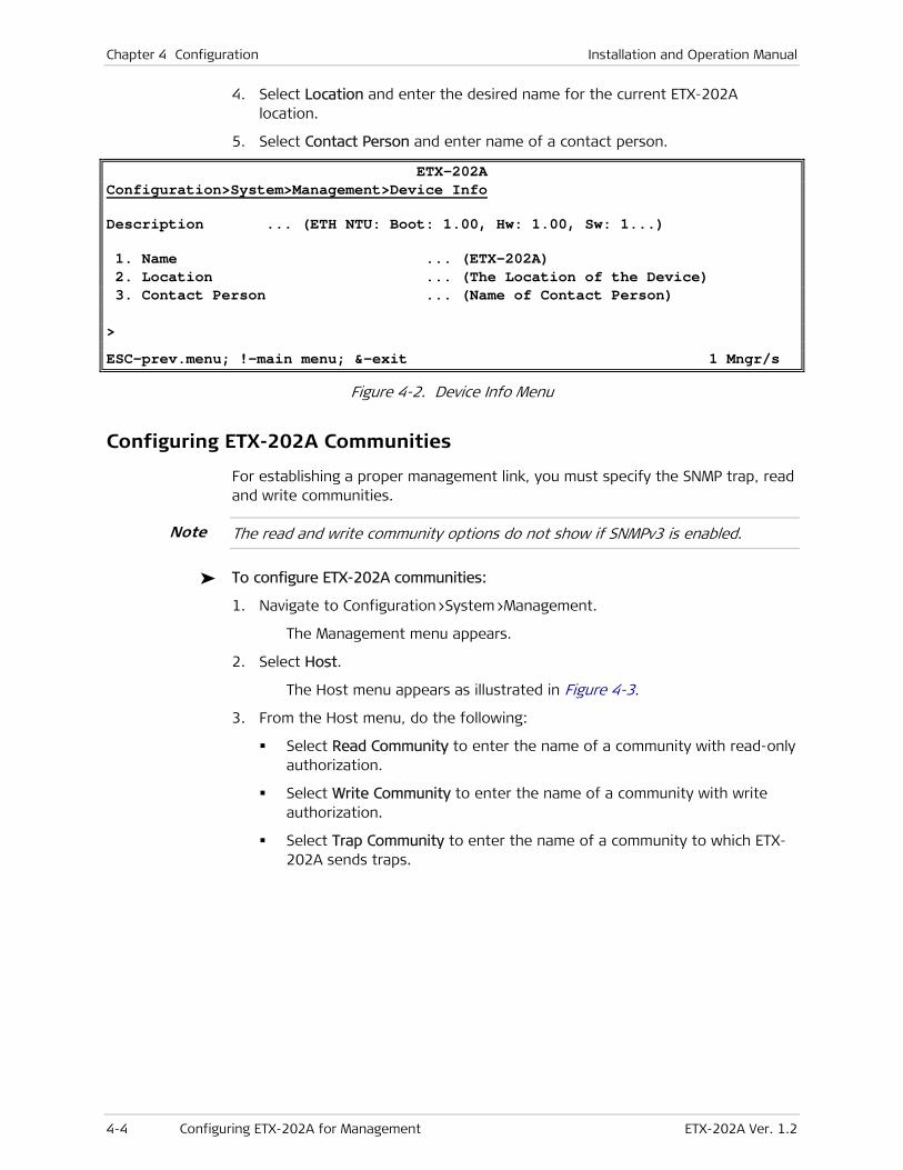
Chapter 4 Configuration Installation and Operation Manual
4-4 Configuring ETX-202A for Management ETX-202A Ver. 1.2
4. Select Location and enter the desired name for the current ETX-202A location.
5. Select Contact Person and enter name of a contact person.
ETX-202A Configuration>System>Management>Device Info
Description ... (ETH NTU: Boot: 1.00, Hw: 1.00, Sw: 1...)
1. Name ... (ETX-202A) 2. Location ... (The Location of the Device) 3. Contact Person ... (Name of Contact Person) > ESC-prev.menu; !-main menu; &-exit 1 Mngr/s
Figure 4-2. Device Info Menu
Configuring ETX-202A Communities
For establishing a proper management link, you must specify the SNMP trap, read and write communities.
The read and write community options do not show if SNMPv3 is enabled.
To configure ETX-202A communities:
1. Navigate to Configuration>System>Management.
The Management menu appears.
2. Select Host.
The Host menu appears as illustrated in Figure 4-3.
3. From the Host menu, do the following:
Select Read Community to enter the name of a community with read-only authorization.
Select Write Community to enter the name of a community with write authorization.
Select Trap Community to enter the name of a community to which ETX-202A sends traps.
Note

Installation and Operation Manual Chapter 4 Configuration
ETX-202A Ver. 1.2 Configuring ETX-202A for Management 4-5
ETX-202A Configuration>System>Management>Host
IP Address ... (0.0.0.0) IP Mask ... (0.0.0.0) Default Gateway ... (0.0.0.0)
1. Read Community ... (Public) 2. Write Community ... (Public) 3. Trap Community ... (Public) 4. Encapsulation > > ESC-prev.menu; !-main menu; &-exit 1 Mngr/s
Figure 4-3. Host (Management) Menu
Configuring SNMPv3
ETX-202A supports the SNMP version 3 entity providing secure SNMP access to the device by authenticating and encrypting packets transmitted over the network.
Follow these steps to configure the SNMPv3 entity:
1. Enable SNMPv3.
2. Add a new user.
3. Add a new notification entry.
4. Assign traps to notification entries.
5. Configure target (NMS) parameters.
6. Specify target address, define its parameter set and assign notification tags.
7. Map SNMPv3 setting to SNMPv1 settings (if necessary).
Enabling SNMPv3
To enable SNMPv3:
1. From the Management menu (Configuration > System > Management), select SNMPv3 and then select Save.
The SNMPv3 Settings line is added to the Management menu.
2. From the Management menu, select SNMPv3 Settings.
The SNMPv3 Settings menu appears as illustrated in Figure 4-4.
The SNMPv3 Settings menu includes the following information:
Engine Boots - The number of times that the SNMP engine has reinitialized since its identification was configured last.
Engine Time - The number of seconds since the last SNMP engine boot.
SNMP Message Size - The maximum length of an SNMP message (in octets) that the SNMP engine can send or receive and process.

Chapter 4 Configuration Installation and Operation Manual
4-6 Configuring ETX-202A for Management ETX-202A Ver. 1.2
ETX-202A Configuration>System>Management>SNMPv3 Settings
Engine Boots (2) Engine Time (276) SNMP Message Size ... (1500) 1. Users > 2. Targets & Notify > 3. SNMPv1/v3 Mapping > 4. SNMPv3 Factory Defaults 5. Summary Target Table [] 6. Summary User Table [] > ESC-prev.menu; !-main menu; &-exit 1 Mngr/s
Figure 4-4. SNMPv3 Settings Menu
Adding SNMPv3 Users
ETX-202A supports up to ten SNMPv3 managers with different authorization and privacy attributes.
Access control policy is defined via the vacmSecurityToGroupTable and vacmAccessTable tables, which can be accessed via an SNMP browser only.
To add an SNMPv3 user:
1. From the Users menu (Configuration > System > Management > SNMPv3 Settings > Users), perform the following:
Select Security Name and enter security name for a new user (up to 32 alphanumeric characters).
Select Authentication Protocol and define the authentication protocol to be used for authenticating the user:
usmNoAuthProtocol - No authentication is performed
usmHMACMD5AuthProtocol - MD5 protocol
usmHMACSHAAuthProtocol - SHA protocol
Select Privacy Protocol and define the type of privacy protocol to be used for encryption:
usmNoPrivProtocol - Privacy protocol is not used)
usmDESPrivProtocol - DES protocol)
Select Authentication Password and define the authentication password of the user. This is not available if authentication has been disabled.
Select Privacy Password and define the private key used for encryption. This is not available if privacy has been disabled.
2. To view the summary of the SNMPv3 user configuration, select Summary User Table from the SNMPv3 Settings (Configuration > System > Management > SNMPv3 Settings) menu.
Note

Installation and Operation Manual Chapter 4 Configuration
ETX-202A Ver. 1.2 Configuring ETX-202A for Management 4-7
To delete an SNMPv3 user:
1. Navigate to the Users menu (Configuration > System > Management > SNMPv3 Settings > Users), and then press <F> or <B> to select an SNMPv3 user.
2. Press <R> to delete the selected user.
Adding Notification Entries
To add a notification entry:
1. From the Targets & Notify menu (Configuration > System > Management > SNMPv3 Settings > Targets & Notify), select Notify.
The Notify menu appears as illustrated in Figure 4-5.
2. From the Notify menu, perform the following:
Name - ASCII string identifying the notification entry
Tag - A tag value to be associated with the current notification entry. This tag will be used to identify the current notification entry when configuring the target address.
ETX-202A Configuration>System>Management>SNMPv3 Settings>Target & Notify>Notify
1. Name ... () 2. Tag ... () > ESC-prev.menu; !-main menu; &-exit 1 Mngr/s
Figure 4-5. Notify Menu
Assigning Traps
One or more traps must be assigned to each notification entry.
To assign traps to notification entries:
1. From the Target & Notify menu, select Trap.
The Trap menu appears as illustrated in Figure 4-6.
2. From the Trap menu, configure the following:
Tag Name - A tag from the list of previously defined notification tags
Trap - A trap to be assigned to the selected tag.
ETX-202A Configuration>System>Management> SNMPv3 Settings> Target & Notify > Trap
1. Tag Name >() 2. Trap >() > ESC-prev.menu; !-main menu; &-exit 1 Mngr/s
Figure 4-6. Trap Menu

Chapter 4 Configuration Installation and Operation Manual
4-8 Configuring ETX-202A for Management ETX-202A Ver. 1.2
Configuring Target Parameters
Target is an SNMPv3 network management station to which ETX-202A is going to send trap notifications. A set of parameters has to be configured and assigned to each target.
To configure target parameters:
1. From the Targets & Notify menu (Configuration > System > Management > SNMPv3 Settings > Targets & Notify), select Target Params.
The Target Params menu appears as illustrated in Figure 4-7.
2. From the Target Params menu, configure the following:
Name - An ASCII string identifying current set of target parameters.
Message Processing Model - The Message Processing Model to be used when generating SNMP messages using this entry:
SNMPv1
SNMPv2c
SNMPv2u
SNMPv3
Security Model - The Security Model to be used when generating SNMP messages using this entry:
Any
SNMPv1
SNMPv2c
User-Based Security Model (USM)
Security Name - Identification of the principal on whose behalf SNMP messages are to be generated using this entry. This can be either SNMPv3 user or SNMPv1/SNMPv2 community string.
Security Level - The level of security to be used when generating SNMP messages using this entry):
noAuthNoPriv - Authorization and privacy are disabled
authNoPriv - Authorization is enabled, privacy is disabled
authPriv - Authorization and privacy are enabled.
ETX-202A Configuration>System>Management>SNMPv3 Settings>Target & Notify>Target Params
1. Name ... () 2. Message Processing Model > () 3. Security Model > () 4. Security Name ... () 5. Security Level > () > ESC-prev.menu; !-main menu; &-exit 1 Mngr/s
Figure 4-7. Target Params Menu

Installation and Operation Manual Chapter 4 Configuration
ETX-202A Ver. 1.2 Configuring ETX-202A for Management 4-9
Configuring Target Address
Each target must have a valid IP address, IP mask. Also, a previously configured parameter set and notification tags must be assigned to the target.
To configure the target address:
1. From the Targets & Notify menu (Configuration > System > Management > SNMPv3 Settings > Targets & Notify), select Target Address.
The Target Address menu appears as illustrated in Figure 4-8.
2. From the Target Address menu, configure the following:
Name - ASCII string identifying the target
IP Address - Valid IP address of the NMS. The IP address must be in xxx.xxx.xxx.xxx:162 format, where 162 is a standard SNMP port used for sending traps.
Params Name - Name of the previously defined target parameter set to be assigned to this target
Address Mask - An IP mask of the NMS
Tag List - List of previously defined notification tags.
3. To view the summary of the SNMPv3 target configuration, select Summary Target Table from the SNMPv3 Settings (Configuration > System > Management > SNMPv3 Settings) menu.
ETX-202A Configuration>System>Management>SNMPv3 Settings>Target & Notify>Target Address
1. Name ... () 2. IP Address ... () 3. Params Name ... () 4. Address Mask ... () 5. Tag List ... () > ESC-prev.menu; !-main menu; &-exit 1 Mngr/s
Figure 4-8. Target Address Menu
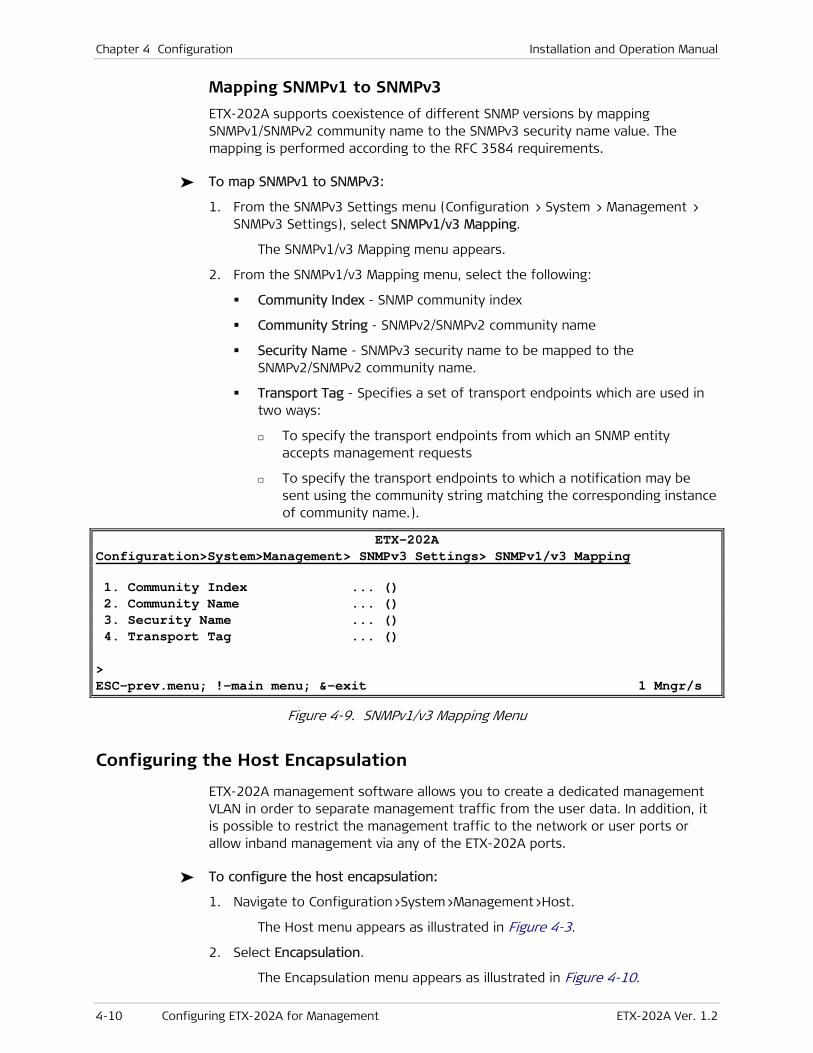
Chapter 4 Configuration Installation and Operation Manual
4-10 Configuring ETX-202A for Management ETX-202A Ver. 1.2
Mapping SNMPv1 to SNMPv3
ETX-202A supports coexistence of different SNMP versions by mapping SNMPv1/SNMPv2 community name to the SNMPv3 security name value. The mapping is performed according to the RFC 3584 requirements.
To map SNMPv1 to SNMPv3:
1. From the SNMPv3 Settings menu (Configuration > System > Management > SNMPv3 Settings), select SNMPv1/v3 Mapping.
The SNMPv1/v3 Mapping menu appears.
2. From the SNMPv1/v3 Mapping menu, select the following:
Community Index - SNMP community index
Community String - SNMPv2/SNMPv2 community name
Security Name - SNMPv3 security name to be mapped to the SNMPv2/SNMPv2 community name.
Transport Tag - Specifies a set of transport endpoints which are used in two ways:
To specify the transport endpoints from which an SNMP entity accepts management requests
To specify the transport endpoints to which a notification may be sent using the community string matching the corresponding instance of community name.).
ETX-202A Configuration>System>Management> SNMPv3 Settings> SNMPv1/v3 Mapping
1. Community Index ... () 2. Community Name ... () 3. Security Name ... () 4. Transport Tag ... () > ESC-prev.menu; !-main menu; &-exit 1 Mngr/s
Figure 4-9. SNMPv1/v3 Mapping Menu
Configuring the Host Encapsulation
ETX-202A management software allows you to create a dedicated management VLAN in order to separate management traffic from the user data. In addition, it is possible to restrict the management traffic to the network or user ports or allow inband management via any of the ETX-202A ports.
To configure the host encapsulation:
1. Navigate to Configuration>System>Management>Host.
The Host menu appears as illustrated in Figure 4-3.
2. Select Encapsulation.
The Encapsulation menu appears as illustrated in Figure 4-10.
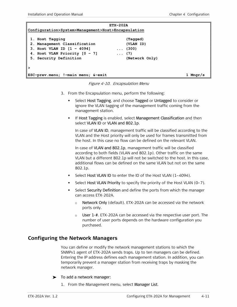
Installation and Operation Manual Chapter 4 Configuration
ETX-202A Ver. 1.2 Configuring ETX-202A for Management 4-11
ETX-202A Configuration>System>Management>Host>Encapsulation
1. Host Tagging (Tagged) 2. Management Classification (VLAN ID) 3. Host VLAN ID [1 - 4094] ... (300) 4. Host VLAN Priority [0 - 7] ... (7) 5. Security Definition (Network Only) > ESC-prev.menu; !-main menu; &-exit 1 Mngr/s
Figure 4-10. Encapsulation Menu
3. From the Encapsulation menu, perform the following:
Select Host Tagging, and choose Tagged or Untagged to consider or ignore the VLAN tagging of the management traffic coming from the management station.
If Host Tagging is enabled, select Management Classification and then select VLAN ID or VLAN and 802.1p.
In case of VLAN ID, management traffic will be classified according to the VLAN and the Host priority will only be used for frames transmitted from the host. In this case no flow can be defined on the relevant VLAN.
In case of VLAN and 802.1p, management traffic will be classified according to both fields (VLAN and 802.1p). Other traffic on the same VLAN but a different 802.1p will not be switched to the host. In this case, additional flows can be defined on the same VLAN but not on the same 802.1p.
Select Host VLAN ID to enter the ID of the Host VLAN (1–4094).
Select Host VLAN Priority to specify the priority of the Host VLAN (0–7).
Select Security Definition and define the ports from which the manager can access ETX-202A.
Network Only (default). ETX-202A can be accessed via the network ports only.
User 1-#. ETX-202A can be accessed via the respective user port. The number of user ports depends on the hardware configuration you purchased.
Configuring the Network Managers
You can define or modify the network management stations to which the SNMPv1 agent of ETX-202A sends traps. Up to ten managers can be defined. Entering the IP address defines each management station. In addition, you can temporarily prevent a manager station from receiving traps by masking the network manager.
To add a network manager:
1. From the Management menu, select Manager List.

Chapter 4 Configuration Installation and Operation Manual
4-12 Configuring ETX-202A for Management ETX-202A Ver. 1.2
The Manager List appears as illustrated in Figure 4-11.
ETX-202A Configuration>System>Management>Manager List
Manager ID IP Address Trap Mask SNMP Traps UDP Port 1. 1.1.1.1 Disable 162
2. 2.2.2.2 Disable 162
| 3. 3.3.3.3 Disable 162
v 4. 4.4.4.4 Disable 162 A – Add R – Remove X – Clear ESC-prev.menu; !-main menu; &-exit; ?-help
Figure 4-11. Manager List Menu
2. In the Manager List, press <A> to add a management station.
The Management List menu switches to the Add mode as illustrated in Figure 4-12.
ETX-202A Configuration>System> Management > Manager List
Manager ID (1) 1. IP Address ... (1.1.1.1) 2. Trap Mask ... (Disable) 3. SNMP Traps UDP Port ... (162) > Please select item <1 to 3> ESC-prev.menu; !-main menu; &-exit 1 Mngr/s
Figure 4-12. Manager List Menu, Add Mode
3. In Add mode, do the following:
Select IP Address, and enter the IP address of the management station.
Select Trap Mask, and select Enable or Disable to mask or unmask traps for the selected management station.
Select SNMP Traps UDP Port and define a UDP port to be used for sending SNMPv1 traps to the network manager.
Select Save All to save the network manager.
Press <Esc> to return to the Edit mode.
To remove a network manager:
1. In the Manager List, select the network manager that you intend to remove.
2. Press <R>.
The selected manager is removed.
To clear the manager list:
• In the Manager List, press <C>.

Installation and Operation Manual Chapter 4 Configuration
ETX-202A Ver. 1.2 Configuring ETX-202A for Management 4-13
All network managers are removed.
Controlling Management Access
You can enable or disable access to the ETX-202A management system via an SNMP, Telnet or Web-based application. By disabling SNMP, Telnet or Web, you prevent unauthorized access to the system when security of the ETX-202A IP address has been compromised. When SNMP, Telnet and Web access are disabled, ETX-202A can be managed via an ASCII terminal only. In addition, you can limit access to the device to only the stations defined in the manager list. Table 4-1 details management access implementation, depending whether the network managers are defined or not.
To define the management access method:
1. From the Management menu (Configuration>System>Management), select Management Access.
The Management Access menu appears as illustrated in Figure 4-13.
2. From the Management Access menu, select the access method:
Telnet/SSH Access. Access using Telnet or Secure Shell
SNMP Access. Access using an SNMP client such as RADview
Web Access. Access via Web based interface using a Web browser.
3. Define the access mode for the management access method you chose. Available management access modes depend on the management access method.
Disable. Telnet, SNMP or Web access disabled.
Enable. Access enabled for anybody via Telnet, SNMP or Web.
Managers Only. Access enabled for management stations listed in the Manager list.
Enable Secure. Secure access enabled via Secure Shell (SSH) or Secure Web (SSL) for anybody.
Managers Only Secure. Secure access enabled via Secure Shell (SSH) or Secure Web (SSL) for management stations listed in the Manager list.
ETX-202A Configuration>System>Management>Management Access
1. User Access > 2. Telnet/SSH access > (Enable) 3. SNMP access > (Disable) 4. Web access > (Enable) 5. Access Policy > 6. RADIUS Parameters > > ESC-prev.menu; !-main menu; &-exit 1 Mngr/s
Figure 4-13. Management Access Menu

Chapter 4 Configuration Installation and Operation Manual
4-14 Configuring ETX-202A for Management ETX-202A Ver. 1.2
Table 4-1. Management Access Implementation
Access Method Mode Allowed to Access ETX-202A
Network Manager(s) Defined
Network Manager(s) not Defined
SNMP Access
Enable Anybody Anybody
Disable Nobody Nobody
Managers Only Only defined
network managers
Nobody
Telnet Access
Enable Anybody Anybody
Disable Nobody Nobody
Managers Only Anybody Only defined
network
managers
SSH Access (Secure Shell)
Enable Secure Anybody Anybody
Disable Nobody Nobody
Managers Only
Secure
Anybody Only defined
network
managers
Web Access
Enable Anybody Anybody
Disable Nobody Nobody
Managers Only Only defined
network managers
Nobody
Secure Web Access (SSL)
Enable Secure Anybody Anybody
Disable Nobody Nobody
Managers Only
Secure
Only defined
network managers
Nobody

Installation and Operation Manual Chapter 4 Configuration
ETX-202A Ver. 1.2 Configuring ETX-202A for Management 4-15
Defining the Access Policy
ETX-202A’s access policy allows configuring authentication protocols using the Radius server. The user authentication is performed according to the selected order. If the first authentication method is not available or the user is not found, the next selected method is used.
To define the access policy:
1. Navigate to Main Menu > Configuration > System > Management, and then select Access Policy.
The Access Policy menu appears.
2. Choose the desired option to configure the first level of authentication (1st Level) as listed below and then press <S>:
Local. ETX-202A uses the locally stored authentication database.
Radius. RADIUS Parameters become available in the Access policy menu and ETX-202A uses the authentication database stored on the Radius server.
2nd Level becomes available. If the user name is not found in the Radius Server database or the password you enter does not match the user name, the authentication fails.
3. Choose the desired option to configure the second level of authentication (2nd Level) as listed below:
None. ETX-202A is only accessible via the 1st level.
Local. ETX-202A uses the locally stored authentication database.
Special rules apply to su (Superuser). If su does not exist in the Radius server database or the system looses the connection to the Radius server, ETX-202A uses the local authentication database to authenticate the user if the 2nd level is set to local.
Configuring Radius Server Parameters
ETX-202A provides connectivity to up to four Radius authentication servers.
To configure Radius server parameters:
1. Navigate to Configuration > System > Management > Management Access.
The Management Access menu appears.
2. Select RADIUS Parameters.
The Radius Server menu appears.
3. Specify the following parameters according to Table 4-2:
Note
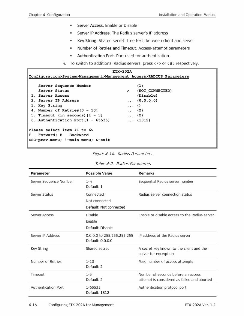
Chapter 4 Configuration Installation and Operation Manual
4-16 Configuring ETX-202A for Management ETX-202A Ver. 1.2
Server Access. Enable or Disable
Server IP Address. The Radius server’s IP address
Key String. Shared secret (free text) between client and server
Number of Retries and Timeout. Access-attempt parameters
Authentication Port. Port used for authentication.
4. To switch to additional Radius servers, press <F> or <B> respectively.
ETX-202A Configuration>System>Management>Management Access>RADIUS Parameters
Server Sequence Number (1) Server Status > (NOT_CONNECTED) 1. Server Access (Disable) 2. Server IP Address ... (0.0.0.0) 3. Key String ... () 4. Number of Retries[0 - 10] ... (2) 5. Timeout (in seconds)[1 - 5] ... (2) 6. Authentication Port[1 - 65535] ... (1812) Please select item <1 to 6> F - Forward; B - Backward ESC-prev.menu; !-main menu; &-exit
Figure 4-14. Radius Parameters
Table 4-2. Radius Parameters
Parameter Possible Value Remarks
Server Sequence Number 1-4
Default: 1
Sequential Radius server number
Server Status Connected
Not connected
Default: Not connected
Radius server connection status
Server Access Disable
Enable
Default: Disable
Enable or disable access to the Radius server
Server IP Address 0.0.0.0 to 255.255.255.255
Default: 0.0.0.0
IP address of the Radius server
Key String Shared secret A secret key known to the client and the
server for encryption
Number of Retries 1-10
Default: 2
Max. number of access attempts
Timeout 1-5
Default: 2
Number of seconds before an access
attempt is considered as failed and aborted
Authentication Port 1-65535
Default: 1812
Authentication protocol port

Installation and Operation Manual Chapter 4 Configuration
ETX-202A Ver. 1.2 Configuring ETX-202A for Management 4-17
Configuring Control Port Parameters
ETX-202A embedded software enables you to configure the serial port parameters, which include specifying terminal baud rate, scrolling window size and security timeout.
To access the Control Port menu:
• From the System Configuration menu, select Control Port.
The Control Port menu appears as illustrated in Figure 4-15.
ETX-202A Configuration>System>Control Port
Terminal Type (VT100) Data Bits (8) Parity (None) Stop Bits (1) Flow Control (None)
1. Baud Rate > (115200 bps) 2. Set Scrolling Window Size[0 - 11] (4) 3. Security Timeout (min)[0 - 60] (10) > ESC-prev.menu; !-main menu; &-exit 1 Mngr/s
Figure 4-15. Control Port Menu
To configure the control port data rate:
1. From the Control Port menu, select Baud Rate.
The Baud Rate menu appears as illustrated in Figure 4-16.
2. Select the desired terminal rate, and then press <Enter>.
• The baud rate must match the one specified in the terminal application used.
• The Baud Rate parameter is masked during Telnet and ConfiguRAD sessions.
ETX-202A Configuration>System>Control Port>Baud Rate
1. 9600 bps 2. 19200 bps 3. 38400 bps 4. 57600 bps 5. 115200 bps ESC-prev.menu; !-main menu; &-exit 1 Mngr/s
Figure 4-16. Baud Rate Menu
Note

Chapter 4 Configuration Installation and Operation Manual
4-18 Configuring ETX-202A for Operation ETX-202A Ver. 1.2
Setting Scrolling Window Size
User-configurable size of the scrolling window specifies the height of the area that is reserved for status information. This area is located at the bottom of the screen.
To set scrolling window size:
• From the Control Port menu (Figure 4-15), select Set Scrolling Window Size to set the size of the status information section at the bottom of the screen in the range of 0 to 11.
Configuring Security Timeout
The timeout specifies a time interval after which ETX-202A automatically disconnects from the supervisory terminal or Telnet host if no input from the user is detected. The timeout value can be in the range of 1 to 60 minutes.
To configure the security timeout:
• From the Control Port menu (Figure 4-15), select Security Timeout to set to in the range of 1 to 60 minutes.
The display is refreshed and a new value appears.
Security timeout value is not valid for the ConfiguRAD management, which is permanently set to 10 minutes.
4.2 Configuring ETX-202A for Operation
The recommended configuration procedure for ETX-202A includes the following stages:
• Setting system level parameters such as link protection and syslog.
• Setting physical layer parameters such as network and user Ethernet interfaces at the physical level
• Configuring ETX-202A at the application level:
Configuring the bridge ports
Configuring QoS parameters
Configuring the Ethernet flows and services.
Configuring OAM parameters.
Note
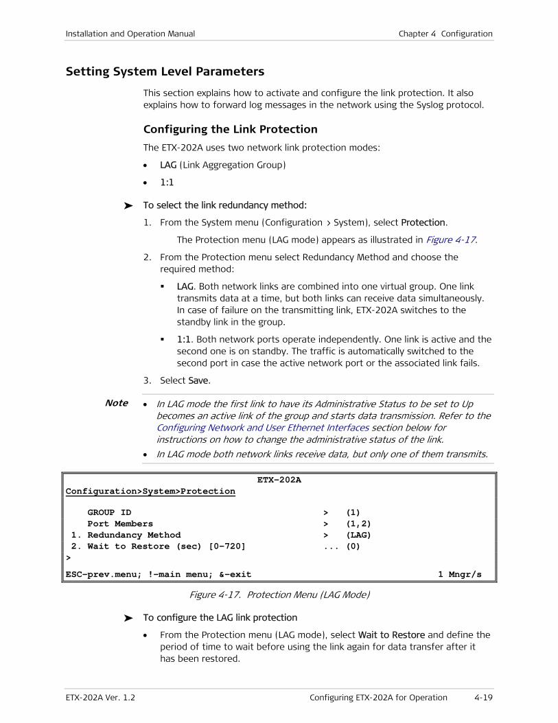
Installation and Operation Manual Chapter 4 Configuration
ETX-202A Ver. 1.2 Configuring ETX-202A for Operation 4-19
Setting System Level Parameters
This section explains how to activate and configure the link protection. It also explains how to forward log messages in the network using the Syslog protocol.
Configuring the Link Protection
The ETX-202A uses two network link protection modes:
• LAG (Link Aggregation Group)
• 1:1
To select the link redundancy method:
1. From the System menu (Configuration > System), select Protection.
The Protection menu (LAG mode) appears as illustrated in Figure 4-17.
2. From the Protection menu select Redundancy Method and choose the required method:
LAG. Both network links are combined into one virtual group. One link transmits data at a time, but both links can receive data simultaneously. In case of failure on the transmitting link, ETX-202A switches to the standby link in the group.
1:1. Both network ports operate independently. One link is active and the second one is on standby. The traffic is automatically switched to the second port in case the active network port or the associated link fails.
3. Select Save.
• In LAG mode the first link to have its Administrative Status to be set to Up becomes an active link of the group and starts data transmission. Refer to the Configuring Network and User Ethernet Interfaces section below for instructions on how to change the administrative status of the link.
• In LAG mode both network links receive data, but only one of them transmits.
ETX-202A Configuration>System>Protection
GROUP ID > (1) Port Members > (1,2) 1. Redundancy Method > (LAG) 2. Wait to Restore (sec) [0-720] ... (0) > ESC-prev.menu; !-main menu; &-exit 1 Mngr/s
Figure 4-17. Protection Menu (LAG Mode)
To configure the LAG link protection
• From the Protection menu (LAG mode), select Wait to Restore and define the period of time to wait before using the link again for data transfer after it has been restored.
Note
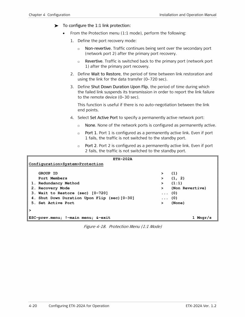
Chapter 4 Configuration Installation and Operation Manual
4-20 Configuring ETX-202A for Operation ETX-202A Ver. 1.2
To configure the 1:1 link protection:
• From the Protection menu (1:1 mode), perform the following:
1. Define the port recovery mode:
Non-revertive. Traffic continues being sent over the secondary port (network port 2) after the primary port recovery.
Revertive. Traffic is switched back to the primary port (network port 1) after the primary port recovery.
2. Define Wait to Restore, the period of time between link restoration and using the link for the data transfer (0–720 sec).
3. Define Shut Down Duration Upon Flip, the period of time during which the failed link suspends its transmission in order to report the link failure to the remote device (0–30 sec).
This function is useful if there is no auto-negotiation between the link end points.
4. Select Set Active Port to specify a permanently active network port:
None. None of the network ports is configured as permanently active.
Port 1. Port 1 is configured as a permanently active link. Even if port 1 fails, the traffic is not switched to the standby port.
Port 2. Port 2 is configured as a permanently active link. Even if port 2 fails, the traffic is not switched to the standby port.
ETX-202A Configuration>System>Protection
GROUP ID > (1) Port Members > (1, 2) 1. Redundancy Method > (1:1) 2. Recovery Mode > (Non Revertive) 3. Wait to Restore (sec) [0-720] ... (0) 4. Shut Down Duration Upon Flip (sec)[0-30] ... (0) 5. Set Active Port > (None) > ESC-prev.menu; !-main menu; &-exit 1 Mngr/s
Figure 4-18. Protection Menu (1:1 Mode)

Installation and Operation Manual Chapter 4 Configuration
ETX-202A Ver. 1.2 Configuring ETX-202A for Operation 4-21
Configuring Syslog
ETX-202A uses the Syslog protocol to generate and transport event notification messages over IP networks to the central Syslog server. The Syslog operation is compliant with the RFC 3164 requirements.
To configure Syslog:
1. From the System menu (Configuration > System), select Syslog.
The Syslog menu appears as illustrated in Figure 4-19.
2. Enable creating a system log and configure the transmitting device parameters as illustrated in Table 4-3.
ETX-202A Configuration>System>Syslog
1. Device Logging Status > (Disable) 2. Device UDP Port([1 – 65535] ... (514) 3. Facility > (Local 1) 4. Severity Level > (Minor) 5. Server Parameters > ESC-prev.menu; !-main menu; &-exit 1 Mngr/s
Figure 4-19. Syslog Menu
Table 4-3. Syslog Menu
Parameter Possible Values Remarks
Device Logging Status Enable
Disable (default)
Disable or enable creating a
system log.
Device UDP Port 1 - 65535 Specifies the UDP port that
transmits Syslog messages.
Facility Local 1 (default) - Local 7 Specifies the software module,
task or function from which the
Syslog messages are sent.
Severity Level Critical
Major
Minor (default)
Warning
Event
Info
Debug
Specify the level of log messages
up to which you want to transmit
them.

Chapter 4 Configuration Installation and Operation Manual
4-22 Configuring ETX-202A for Operation ETX-202A Ver. 1.2
3. To configure the receiving device, from the Syslog menu, select Server Parameters.
The server parameters appear as illustrated in Figure 4-20.
4. Configure the server parameters as required. To navigate between servers, press <F> to rising sequence numbers or <B> to lower sequence numbers.
5. Repeat the instructions above for the additional servers as required.
ETX-202A Configuration>System>Syslog
Server Sequence Number ... (1) 1. Server Access > (Disable) 2. Server IP Address ... (0.0.0.0) 3. Server UDP Port[1 – 65535] ... (514) ESC-prev.menu; !-main menu; &-exit 1 Mngr/s
Figure 4-20. Server Menu
Table 4-4. Server Menu
Parameter Possible Values Remarks
Server Sequence Number 1 – 5 This value is read-only.
Server Access Enable
Disable
This parameter becomes
available when you
specified the server’s IP
address.
If the server access is
enabled for system logs,
parameters become
unavailable for editing.
Server IP Address 0.0.0.0 – 255.255.255.255 The IP address of the
receiving device (server)
Server UDP Port 1 – 65535 The UDP port of the
receiving device (server)

Installation and Operation Manual Chapter 4 Configuration
ETX-202A Ver. 1.2 Configuring ETX-202A for Operation 4-23
Configuring Physical Layer Parameters
ETX-202A has two fiber optic or copper Gigabit Ethernet network ports and up to four fiber optic or copper Gigabit Ethernet user ports. The following parameters can be configured for the Ethernet ports at the physical level:
• Fault propagation (user ports)
• Autonegotiation (10/100/1000BaseT and 1000BaseX ports)
• Maximum advertised capability for autonegotiation procedure
• Data rate and duplex mode, when autonegotiation is disabled
• Fault propagation, Wait-to-Restore time
• Link OAM (802.3ah) mode
• Flow control
• Administrative status
• User name.
Configuring Network and User Ethernet Interfaces
To configure an Ethernet port:
1. From the Physical Layers menu (Configuration > Physical Layers), select Ethernet.
The Ethernet menu appears.
2. Press <F> to select a network or user Ethernet port.
3. From the Ethernet Network or Ethernet User menu, configure the following:
Administrative Status:
Up. The port is enabled
Down. No traffic and no events/alarm through this port.
User Name. Description of the current network or user port
Auto Negotiation:
Enable. Autonegotiation is enabled
Disable. Autonegotiation is disabled.
Max Capability Advertised. The highest traffic handling capability to be advertised during the autonegotiation process. This parameter is relevant for RJ-45 copper ports only. For fiber optic ports, it is permanently set to 1000BaseX Full Duplex. The following settings are possible:
10BaseT Full Duplex
100BaseT Full Duplex
1000BaseX Full Duplex.

Chapter 4 Configuration Installation and Operation Manual
4-24 Configuring ETX-202A for Operation ETX-202A Ver. 1.2
Speed & Duplex. Data rate and duplex mode of the Ethernet port. This parameter is only relevant for RJ 45 copper ports and shows when Auto Negotiation is disabled. For fiber optic ports it is permanently set to 1000BaseX Full Duplex.
10BaseT Full Duplex
100BaseT Full Duplex
1000BaseX Full Duplex.
Fault Propagation. When enabled, fault propagation mechanism disconnects the current user Ethernet interfaces, when the network interface is down. Fault propagation is available only for the user ports.
Enable. Fault propagation is enabled
Disable. Fault propagation is disabled.
Link OAM (802.3ah). Controls OAM link operation for the current port as per IEEE 802.3ah requirements.
Enable. Link OAM (802.3ah) operation is enabled
Disable. Link OAM (802.3ah) operation is disabled.
4. Select Save to finish configuration of the physical layer of the ETX-202A network and user ports.
ETX-202A Configuration>Physical Layers >Ethernet
Port Label (3) Ethernet Port (User1) 1. Administrative Status (Up) 2. User Name (ETH 3) 3. Auto-Negotiation (Enable) 4. Max Capability Advertised\Speed & Duplex (1000baseX Full Duplex) 5. Fault Propagation (Disable) 6. Link OAM (802.3ah) (Disable) ESC-prev.menu; !-main menu; &-exit 1 Mngr/s
Figure 4-21. Ethernet Menu (User Port)

Installation and Operation Manual Chapter 4 Configuration
ETX-202A Ver. 1.2 Configuring ETX-202A for Operation 4-25
Configuring the Fault Propagation Wait-to-Restore Time
If the fault propagation feature is enabled, you can also specify the wait-to-restore (WTR) time for the user interfaces. WTR is the time period ETX-202A waits before enabling user interfaces once the network interface is restored.
To configure the fault propagation WTR time:
• From the Physical Layers menu (Figure 4-22), select Fault Propagation WTR and select the required fault propagation WTR in the range of 0–3600 seconds. 0 disables the WTR.
ETX-202A Configuration>Physical Layers
1. Ethernet >
2. Fault Propagation WTR (sec) [0 – 3600] ... (0) ESC-prev.menu; !-main menu; &-exit 1 Mngr/s
Figure 4-22. Physical Ports Menu
Configuring ETX-202A at the Application Level
At the application level you can configure the following operation entities:
• QoS
• OAM
• Flows.

Chapter 4 Configuration Installation and Operation Manual
4-26 Configuring ETX-202A for Operation ETX-202A Ver. 1.2
Configuring the Quality of Service (QoS)
The ETX-202A Quality of Service (QoS) parameters include the following profiles:
• CoS profiles
• Marking profiles
• Bandwidth profiles
• Queue profiles
• Scheduler profiles.
These profiles can be applied to the traffic flows to ensure the desired flow classification and prioritization.
Creating a CoS Profile
CoS profiles are used to convert a user priority (P-bit, ToS or DSCP) into internal priority queues (classes of service). ETX-202A has pre-defined CoS profiles:
• UserCosPbits, when the ingress traffic is prioritized according to the 802.1p requirements, user ports only.
• NetworksCosPbits, when the ingress traffic is prioritized according to the 802.1p requirements, network ports only.
• UserCosDSCP, when the ingress traffic is prioritized according to DSCP.
• UserCosTos, when the ingress traffic is prioritized according to ToS (IP Precedence).
For each profile, the user has to define the CoS mapping to map the user priority values to the internal CoS values.
The internal queues are combined into a queue profile, which can be assigned to a network or user port.
To configure the CoS mapping for the 802.1p method:
1. Navigate to Configuration > Application > QoS.
The QoS menu appears.
2. From the QoS menu, select CoS Profiles.
The CoS Profiles menu appears as illustrated in Figure 4-23.
ETX-202A Configuration>Application>QoS>CoS Profiles
Profile ID[1 – 4]... (1) Ingress Priority Method> (802.1p) 1. Profile Name... (UsersCosPbits) 2. CoS Mapping > > F-Forward, B-Backward ESC-prev.menu; !-main menu; &-exit
Figure 4-23. CoS Profiles Menu

Installation and Operation Manual Chapter 4 Configuration
ETX-202A Ver. 1.2 Configuring ETX-202A for Operation 4-27
3. Press <F> to select UsersCosPbits or NetworksCosPbits.
The selected profile appears under Profile Name.
4. Select CoS Mapping.
The associated CoS Mapping menu appears as illustrated in Figure 4-24.
5. From the CoS Mapping menu, select a user priority tag value 0–7 and map it to a priority queue (0–7).
ETX-202A Configuration>Application>QoS>CoS Profiles>CoS Mapping
802.1p CoS 1. Tag Value 0 [0 – 7] ... (0) 2. Tag Value 1 [0 – 7] ... (0) 3. Tag Value 2 [0 – 7] ... (1) 4. Tag Value 3 [0 – 7] ... (1) 5. Tag Value 4 [0 – 7] ... (2) 6. Tag Value 5 [0 – 7] ... (2) 7. Tag Value 6 [0 – 7] ... (5) 8. Tag Value 7 [0 – 7] ... (5) > Please select item ESC-prev.menu; !-main menu; &-exit 1 Mngr/s
Figure 4-24. CoS Mapping Menu (802.1p Method)
To configure the CoS mapping for the DSCP method:
1. Navigate to the CoS Profiles menu (Figure 4-23)
2. Press <F> to select UsersCosDSCP.
The selected profile appears under Profile Name.
3. Select CoS Mapping.
The CoS Mapping menu associated with the DSCP method appears as illustrated in Figure 4-25.
4. From the CoS Mapping menu, select a user DSCP tag value 0–63 and map it to a priority queue (0–7). To scroll through the screen, press <N> or <P> respectively.

Chapter 4 Configuration Installation and Operation Manual
4-28 Configuring ETX-202A for Operation ETX-202A Ver. 1.2
ETX-202A Configuration>Application>QoS>CoS Profiles>CoS Mapping
DSCP CoS 1. Tag Value 0 [0 – 7] ... (0) 2. Tag Value 1 [0 – 7] ... (0) 3. Tag Value 2 [0 – 7] ... (0) 4. Tag Value 3 [0 – 7] ... (0) 5. Tag Value 4 [0 – 7] ... (0) 6. Tag Value 5 [0 – 7] ... (0) 7. Tag Value 6 [0 – 7] ... (0) 8. Tag Value 7 [0 – 7] ... (0) > Please select item ESC-prev.menu; !-main menu; &-exit 1 Mngr/s
Figure 4-25. CoS Mapping Menu (DSCP Method)
To configure the CoS mapping for the IP Precedence method:
1. Navigate to the CoS Profiles menu (Figure 4-23).
2. Press <F> to select UsersCosToS.
The selected profile appears under Profile Name.
3. Select CoS Mapping.
The CoS Mapping menu associated with the IP Precedence method appears as illustrated in Figure 4-26.
4. From the CoS Mapping menu, select a user ToS tag value 0–7 and map it to a priority queue (0–7).
ETX-202A Configuration>Application>QoS>CoS Profiles>CoS Mapping
IP Precedence CoS 1. Tag Value 0 [0 – 7] ... (0) 2. Tag Value 1 [0 – 7] ... (0) 3. Tag Value 2 [0 – 7] ... (0) 4. Tag Value 3 [0 – 7] ... (0) 5. Tag Value 4 [0 – 7] ... (0) 6. Tag Value 5 [0 – 7] ... (0) 7. Tag Value 6 [0 – 7] ... (0) 8. Tag Value 7 [0 – 7] ... (0) > Please select item ESC-prev.menu; !-main menu; &-exit 1 Mngr/s
Figure 4-26. CoS Mapping Menu (IP Precedence Method)
Defining Marking Profiles
Marking profiles map the internal CoS queues to the egress priority tags. Currently ETX-202A supports only one marking profile.

Installation and Operation Manual Chapter 4 Configuration
ETX-202A Ver. 1.2 Configuring ETX-202A for Operation 4-29
To define a marking profile:
1. Navigate to Configuration > Application > QoS > Marking Profiles.
The Marking Profiles menu appears.
2. Press <F> to navigate to the desired Marking profile. The pre-defined Marking profiles are labeled Marking 1-4 by default.
3. Select Marking.
The associated Marking menu appears.
4. From the Marking menu (Configuration > Application > QoS > Marking Profiles > Marking), map each CoS value (0–7) to a priority tag (0–7) to be assigned to traffic leaving the corresponding internal priority queue.
ETX-202A Configuration>Application>QoS>Marking Profiles>Marking
CoS Marking 1. CoS Value 0[0 - 7] ... (0) 2. CoS Value 1[0 - 7] ... (0) 3. CoS Value 3[0 - 7] ... (1) 4. CoS Value 3[0 - 7] ... (1) 5. CoS Value 4[0 - 7] ... (2) 6. CoS Value 5[0 - 7] ... (5) 7. CoS Value 6[0 - 7] ... (1) 8. CoS Value 7[0 - 7] ... (6) > ESC-prev.menu; !-main menu; &-exit 1 Mngr/s
Figure 4-27. Marking Menu
Defining Bandwidth Profiles
ETX-202A supports up to 64 bandwidth profiles that can be applied to the ingress traffic flows. ETX-202A controls the egress bandwidth utilization by defining committed/excessive information rate and committed/excessive burst size.
To define a bandwidth profile:
1. Navigate to Configuration > Application > QoS.
The QoS profile appears.
2. Select Bandwidth Profiles,
The Bandwidth Profiles menu appears as illustrated in Figure 4-28.
3. To add a new profile or select an existing profile, press <A> to add new profiles, or press <F> to navigate to existing profiles.
Parameters appear as illustrated in Figure 4-28.
4. Configure the bandwidth profile according to Table 4-5.

Chapter 4 Configuration Installation and Operation Manual
4-30 Configuring ETX-202A for Operation ETX-202A Ver. 1.2
ETX-202A Configuration>Application>QoS>Bandwidth Profiles
1. Profile ID[1 - 64] ... (1) 2. Profile Name ... (Profile1) 3. CIR (Kbps)[0 - 100000] ... (0) 4. CBS (Bytes)[0-32767] ... (0) 5. EIR (Kbps)[0-100000] ... (100000) 6. EBS (Bytes)[0-32767] ... (32767) Policed Traffic (All) Color Mode (Blind) Coupling Flag (Disable) > Please select item <1 to 6> A - Add New Profile ; F - Forward ; D - Delete ESC-prev.menu; !-main menu; &-exit 1 Mngr/s
Figure 4-28. Bandwidth Profiles Menu
Table 4-5. Bandwidth Profiles Parameters
Parameter Function Values
Profile ID Selects an ingress bandwidth profile identification
number
1–64
Default: 1
Profile Name Assigns a name to the BW profile Alphanumeric string of up to 20
characters
Default: Profile 1
CIR Defines the Committed Information Rate (CIR) for the
current profile. The CIR specifies a bandwidth with
committed service guarantee (“green bucket” rate).
Granularity: 64 Kbps up to 130 Mbps and
512 Kbps up to 1 Gbps
0–100,000 kbps
Default: 0
CBS Defines the Committed Burst Size (CBS) for the current
profile. The CBS specifies the maximum guaranteed
burst size (“green bucket” size).
1 x Byte granularity
0–32,767 kbps
Default: 0
EIR Defines the Excess Information Rate (EIR). The EIR
specifies an extra bandwidth with no service guarantee
(“yellow bucket” rate).
Granularity: 64 Kbps up to 130 Mbps and
512 Kbps up to 1 Gbps
0–100,000 kbps
Default: 100,000
EBS Defines the Excess Burst Size (EBS). The EBS specifies
the extra burst with no service guarantee (“yellow
bucket” size).
1 x Byte granularity
0–32,767 kbps
Default: 32,767
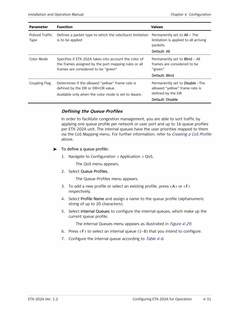
Installation and Operation Manual Chapter 4 Configuration
ETX-202A Ver. 1.2 Configuring ETX-202A for Operation 4-31
Parameter Function Values
Policed Traffic
Type
Defines a packet type to which the rate/burst limitation
is to be applied
Permanently set to All – The
limitation is applied to all arriving
packets.
Default: All
Color Mode Specifies if ETX-202A takes into account the color of
the frames assigned by the port mapping rules or all
frames are considered to be “green”
Permanently set to Blind – All
frames are considered to be
“green”
Default: Blind
Coupling Flag Determines if the allowed “yellow” frame rate is
defined by the EIR or EIR+CIR value.
Available only when the color mode is set to Aware.
Permanently set to Disable –The
allowed “yellow” frame rate is
defined by the EIR
Default: Disable
Defining the Queue Profiles
In order to facilitate congestion management, you are able to sort traffic by applying one queue profile per network or user port and up to 16 queue profiles per ETX-202A unit. The internal queues have the user priorities mapped to them via the CoS Mapping menu. For further information, refer to Creating a CoS Profile above.
To define a queue profile:
1. Navigate to Configuration > Application > QoS.
The QoS menu appears.
2. Select Queue Profiles.
The Queue Profiles menu appears.
3. To add a new profile or select an existing profile, press <A> or <F> respectively.
4. Select Profile Name and assign a name to the queue profile (alphanumeric string of up to 20 characters).
5. Select Internal Queues to configure the internal queues, which make up the current queue profile.
The Internal Queues menu appears as illustrated in Figure 4-29.
6. Press <F> to select an internal queue (1–8) that you intend to configure.
7. Configure the internal queue according to Table 4-6.

Chapter 4 Configuration Installation and Operation Manual
4-32 Configuring ETX-202A for Operation ETX-202A Ver. 1.2
ETX-202A Configuration>Application>QoS>Queue Profiles>Internal Queues
Internal Queue ID[1 - 8] ... (1) Highest Priority Internal Queue 8 1. Scheduling > (WFQ) 2. Weight[1 - 32] ... (1) 3. Queues Length (Bytes)[64 - 32767] ... (10000) Please select item <1 to 3> F - Forward ; B – Backward ; S - Save ESC-prev.menu; !-main menu; &-exit 1 Mngr/s
Figure 4-29. Internal Queue Menu
Table 4-6. Internal Queue Parameters
Parameter Function Values
Scheduling Defines the queue scheduling method.
Currently, if one of the internal queues is
configured to the WFQ mode, the queues
with the higher priority cannot be
configured to the strict mode.
Note: In configurations with Strict and WFQ queues, the WFQ frames are transmitted only after the transmission of frames associated with the Strict queues is completed.
Strict – High-priority queues that are
always serviced first. If a lower-priority
queue is being serviced and a packet
enters a higher queue, that queue is
serviced immediately.
WFQ – Weighted Fair Queuing, if one port
does not transmit, its unused bandwidth
is shared by the ‘transmitting’ queues
according to the assigned weight.
Default: WFQ
Weight Determines the weight of an internal queue
when the scheduling weight is configured to
WFQ
1–32
Default: 1
Queue Length Defines the queue length. 0 –32,000 bytes
Default: 10,000
Configuring the OAM
ETX-202A features the capabilities listed below for providing operation, administration, and maintenance (OAM) in packet-switched networks. For additional information regarding the OAM functionality, refer to Appendix C.
• Continuity check
• Non-intrusive loopback, which used to detect loss of bidirectional continuity.
• Performance measurements (per service).
To configure the OAM:
1. From the OAM (Configuration > Applications > OAM) menu, select End-To-End.
OAM options appear listed.

Installation and Operation Manual Chapter 4 Configuration
ETX-202A Ver. 1.2 Configuring ETX-202A for Operation 4-33
ETX-202A Configuration>Application>OAM>End-To-End
1. MD Names > 2. Standard OAM MAC Address ... (01-80-C2-00-00-30) 3. Standard OAM EtherType[0 - ffff] ... (8902) 4. Flows > Please select item <1 to 4> ESC-prev.menu; !-main menu; &-exit 1 Mngr/s
Figure 4-30. End-To-End Menu
Table 4-7. End-To-End Menu
Parameter Possible Values Remarks
MD Names Maintenance Entity Group ID’s domain name.
Standard OAM
MAC Address
Specifies the MAC Address for Operation and Maintenance.
Default: 01-80-C2-00-00-30
Standard OAM
EtherType
0 - ffff Specifies the Operation and Maintenance EtherType.
Default: 8902
Flows Flows
2. If necessary, modify the OAM MAC Address and/or the Standard OAM Ether Type.
3. Click Save.
Configuring a Maintenance Domain
ETX-202A lets you add or remove maintenance domains (MDs) as explained below.
To view and edit existing MDs:
1. To view configured MDs, press <F> or <B> to scroll forward or backward respectively.
The associated MD ID, the MD format and the MD name appear.
2. Modify the MD format and the MD name as desired.
3. Select Save.
To add a maintenance domain (MD):
1. From the End-to-End menu, select MD Names.
The MD Names menu appears.
2. Press <A>.
The new MD ID appears as illustrated in Figure 4-31 and you are able to choose the MD format and assign an MD name as outlined in Table 4-8.

Chapter 4 Configuration Installation and Operation Manual
4-34 Configuring ETX-202A for Operation ETX-202A Ver. 1.2
ETX-202A Configuration>Application>OAM>End-To-End>MD Names
MD ID[1 – 64] ... (1)
1. MD Format > (String) 2. MD Name ... (None) Please select item <1 to 4> A - Add New MD Name; F – Forward; D - Delete ESC-prev.menu; !-main menu; &-exit 1 Mngr/s
Figure 4-31. MD Names Menu
Table 4-8. MD Parameters
Parameter Possible Values Remarks
MD ID The maintenance domain’s ID
MD Format None
String
DNS Like
MAC + UINT
Indicates maintenance group entity ID’s (MEG ID) domain
name format.
Default: String
MD Name Indicates maintenance group entity ID’s (MEG ID) domain
name. One MD name (None) remains by default.
Default: The latest configured name or none
To delete an MD:
• To delete an MD, press <D>.
Configuring an OAM Flow
ETX-202A lets you add or remove OAM flows.
In some cases, the user interface may refer to flows also as EVCs.
To view existing flows:
1. From the End-To-End (Configuration > Applications > OAM > End-To-End) menu, select Flows.
Flow options appear listed.
2. To view configured flows, press <F> to scroll forward or <B> to scroll backward through the list.
To add a flow:
1. To add a flow, press <A>.
The new flow appears as illustrated in Figure 4-32.
2. Configure the flow parameters as outlined in Table 4-9.
3. Click Save.
Note

Installation and Operation Manual Chapter 4 Configuration
ETX-202A Ver. 1.2 Configuring ETX-202A for Operation 4-35
ETX-202A Configuration>Applications>OAM>End-To-End>Flows Flow[1 – 8] ... (1) 1. Flow Name ... (Put your String here) 2. SP VLAN[1 – 4094] ... (1) 3. Protocol Type (Standard) 4. MAID > 5. MEP > A-Add New Flow ; F-Forward ; B-Backward ; D-Delete ESC-Previous menu; !-Main menu; &-Exit
Figure 4-32. Flows Menu
Table 4-9. Flows Parameters
Parameter Possible Values Remarks
Flow 1 – 8 Flow ID
Flow Name Assign a name to the relevant flow.
SP VLAN 1 – 4094 Specify the VLAN used to send the OAM for the specified Maintenance
Entity Group (MEP).
Protocol Type Proprietary
Standard
Proprietary refers to RAD’s proprietary OAM protocol. If you choose
Proprietary, you will have to only configure MEP.
Default: Standard
MAID Refers to the Maintenance Association ID. This parameter only shows if
Protocol Type is set to Standard.
Refer to Table 4-10 for additional information.
MEP Refers to the Maintenance Entity Group End Point.
Refer to Table 4-11for additional information.
To configure the maintenance association’s ID (MAID):
1. Select MAID.
The MAID menu appears as illustrated in Figure 4-33.
2. Configure MAID as outlined in Table 4-10.
3. Click Save.
ETX-202A Configuration>Applications>OAM>End-To-End>Flows>MAID Flow ID ... (Put your string here) 1. MD ID[1 – 64] ... (1) MD Format > (None) MD Name (None) 2. MA Format > (String) 3. MA Name ... (DEFAULT) ESC-Previous menu; !-Main menu; &-Exit
Figure 4-33. MAID Menu

Chapter 4 Configuration Installation and Operation Manual
4-36 Configuring ETX-202A for Operation ETX-202A Ver. 1.2
Table 4-10. MAID Parameters
Parameter Possible Values Remarks
Flow ID Displays the Flow ID.
Flow ID 1 - 64 Select the ID of the desired maintenance domain (MD ID)
MD Format Displays the selected maintenance domain’s format
(MD Format)
MD Name Displays the name assigned to the selected maintenance
domain (MD Name).
MA Format String
Primary Vlan
Unsigned Int 16
ICC
Select the maintenance association’s format (MA Format).
Default: String
MA Name Assign a name to the maintenance association (MA Name).
Default name: DEFAULT
To configure the maintenance entity group’s end point (MEP)
1. Select MEP.
The MEP menu appears as illustrated in Figure 4-34.
2. Configure MEP as outlined in Table 4-11.
3. Select Save.
ETX-202A Configuration>Applications>OAM>End-To-End>Flows>MEP Flow ID ... (Put your string here) 1. Local ID[0 – 8191] ... (0) 2. OAM Destination Address Type (Multicast) 3. Remote ID > (-) 4. MD Level[0 - 7] ... (3) 5. OAM Mode > (Disable) 6. Continuity Verification Mode > (CC Based) 7. OAM Destination MAC Address > (0120D2000103) 8. Default CC Priority > (0) 9. CC Interval > (1 Second) 10. Services ESC-Previous menu; !-Main menu; &-Exit
Figure 4-34. MEP Menu
Table 4-11. MEP Parameters
Parameter Possible Values Remarks
Flow ID Displays the Flow ID.
Local ID 0 - 8191 Indicates the maintenance entity group’s end point.
Default: 1

Installation and Operation Manual Chapter 4 Configuration
ETX-202A Ver. 1.2 Configuring ETX-202A for Operation 4-37
Parameter Possible Values Remarks
OAM Destination
Address Type
Multicast
Unicast
Determines the MAC address sent in OAM messages, which
may be either RADs proprietary multicast address or a user
defined unicast address.
Default: Multicast
Remote ID 0 – 8191 The Remote MEP ID is the ID that incoming OAM messages
will be identified by. Every unit’s ID must remain unique. The
local and remote ID must therefore not be identical.
MD Level 0 - 7 OAM domain level
Default: 3
OAM Mode Disabled
Initiate
React
Determines the OAM behavior.
Disabled: No CC performed,
Initiate: The unit will initiate and respond to OAM messages,
React: The unit will respond to OAM messages, but not
initiate them.
Default: Disabled
Continuity
Verification Mode
Disabled
LB Based
CC Based
Determines the CC behavior. LB Based is used only for RAD
proprietary.
Default: Disabled
Note: Available if the OAM Mode is set to Initiate or React.
OAM Destination
MAC Address
Unicast Mac Address Determines the MAC address sent in OAM messages.
configurable only for Unicast MAC Address.
Default: 0120D2000100 + MD Level in RAD Proprietary,
Standard OAM MAC Address + MD Level in Standard.
Note:
• Appears if the OAM Mode is set to Initiate.
• Configurable if the OAM Destination MAC Address Type is set to Unicast.
Default CC
Priority
The priority CFM messages will be sent if no service is
defined on the flow. If a service is defined, the CC will be
performed at the highest priority service on the flow.
Note: Appears if the OAM Mode is set to Initiate.
CC Interval 100ms
1 sec
10 sec
1 min
10 min
Sets the CC interval between messages.
Default: 1 sec
Services Refer to Figure 4-35 and Table 4-12

Chapter 4 Configuration Installation and Operation Manual
4-38 Configuring ETX-202A for Operation ETX-202A Ver. 1.2
To configure the Services:
1. From the MEP menu (Configuration > Applications > OAM > End-To-End > Flows > MEP), select Services.
The Services menu appears.
2. Configure the parameters as detailed below and then select Save.
ETX-202A Configuration>Applications>OAM>End-To-End>Flows>MEP>Services Service ... (1) 1. Performance Monitoring ... (Enabled) 2. Priority ... (0) 3. Delay Objective ... (0) 4. Delay Variation Objective ... (0) Event Report 5. Frame Loss Ratio > 6. Frames Above Delay > 7. Frames Above Delay Variation > 8. Unavailability Ratio > ESC-Previous menu; !-Main menu; &-Exit
Figure 4-35. Services Menu
Table 4-12. Services Parameters
Parameter Possible Values Remarks
Service 1 – 3 Three services will be automatically created on each
defined flow.
Performance Monitoring Enabled
Disabled
Enables/disables Performance Monitoring
Default: Disabled
Priority 0 – 7 Determines the P bit value sent inside this OAM
message that originates from this service.
Default: 0
Delay Objective 1 – 1000 Determines the delay objective for the specified
service.
Default: 0
Delay Variation Objective 1 – 1000 Determines the delay variation objective for the
specified service
Default: 0
Frame Loss Ratio Available after saving the service parameters
Refer to Figure 4-36 and Table 4-13
Frames Above Delay Available after saving the service parameters
Refer to Figure 4-37 and Table 4-14

Installation and Operation Manual Chapter 4 Configuration
ETX-202A Ver. 1.2 Configuring ETX-202A for Operation 4-39
Parameter Possible Values Remarks
Frames Above Delay Variation Available after saving the service parameters
Refer to Figure 4-38 and Table 4-15
Unavailability Ratio Available after saving the service parameters
Refer to Figure 4-39 and Table 4-16
ETX-202A Configuration>Applications>OAM>End To End>Flows>Services>Frame Loss Ratio 1. Rising Threshold ... (0) 2. Falling Threshold ... (0) 3. Event Reporting Type ... (Log) Please select item <1 to 1> ESC-prev.menu; !-main menu; &-exit
Figure 4-36. Frame Loss Ratio Menu Screen
Table 4-13. Frame Loss Ratio Menu
Parameter Possible Values Remarks
Rising Threshold 1 – 4294967296
For Unavailability Ratio /
Frame Loss Ratio, the values
are: 1E-3,1E-4,1E-5,
1E-6,1E-7,1E-8,1E-9,1E-10
A value above this threshold within the sampling
interval for the specified counter will be considered
a rising event.
Default: 1
Falling Threshold 1 – 4294967296
For Unavailability Ratio /
Frame Loss Ratio, the values
are: 1E-3,1E-4,1E-5,
1E-6,1E-7,1E-8,1E-9,1E-10
A value above this threshold within the sampling
interval for the specified counter will be considered
a falling event.
Default: 1
Event Reporting Type None
Log
SNMP Trap
Trap and Log
The Event type sent out after passing the threshold.
Default: Log

Chapter 4 Configuration Installation and Operation Manual
4-40 Configuring ETX-202A for Operation ETX-202A Ver. 1.2
ETX-202A Configuration>Applications>OAM>End To End>Flows>Services>Frames Above Delay 1. Rising Threshold ... (0) 2. Falling Threshold ... (0) 3. Sampling Interval ... (0) 4. Event Reporting Type ... (Trap and Log) Please select item <1 to 1> ESC-prev.menu; !-main menu; &-exit
Figure 4-37. Frames Above Delay Menu Screen
Table 4-14. Frames Above Delay Menu
Parameter Possible Values Remarks
Rising Threshold 1 – 4294967296
For Unavailability Ratio /
Frame Loss Ratio, the values
are: 1E-3,1E-4,1E-5,
1E-6,1E-7,1E-8,1E-9,1E-10
A value above this threshold within the sampling
interval for the specified counter will be considered
a rising event.
Default: 1
Falling Threshold 1 – 4294967296
For Unavailability Ratio /
Frame Loss Ratio, the values
are: 1E-3,1E-4,1E-5,
1E-6,1E-7,1E-8,1E-9,1E-10
A value above this threshold within the sampling
interval for the specified counter will be considered
a falling event.
Default: 1
Sampling Interval 1 – 4294967296 The interval in seconds above which the data is
sampled and compared with the rising and falling
thresholds.
Event Reporting Type None
Log
SNMP Trap
Trap and Log
The Event type sent out after passing the threshold.
Default: Trap and Log
ETX-202A Configuration>Applications>OAM>End To End>Flows>Services>Frames Above Delay 1. Rising Threshold ... (0) 2. Falling Threshold ... (0) 3. Sampling Interval ... (0) 4. Event Reporting Type ... (Trap) Please select item <1 to 1> ESC-prev.menu; !-main menu; &-exit
Figure 4-38. Frames Above Delay Variation Menu

Installation and Operation Manual Chapter 4 Configuration
ETX-202A Ver. 1.2 Configuring ETX-202A for Operation 4-41
Table 4-15. Frames Above Delay Variation Parameters
Parameter Possible Values Remarks
Rising Threshold 1 – 4294967296
For Unavailability Ratio /
Frame Loss Ratio, the values
are: 1E-3,1E-4,1E-5,
1E-6,1E-7,1E-8,1E-9,1E-10
A value above this threshold within the sampling
interval for the specified counter will be considered
a rising event.
Default: 1
Falling Threshold 1 – 4294967296
For Unavailability Ratio /
Frame Loss Ratio, the values
are: 1E-3,1E-4,1E-5,
1E-6,1E-7,1E-8,1E-9,1E-10
A value above this threshold within the sampling
interval for the specified counter will be considered
a falling event.
Default: 1
Sampling Interval 1 – 4294967296 The interval in seconds above which the data is
sampled and compared with the rising and falling
thresholds.
Event Reporting Type None
Log
SNMP Trap
Trap and Log
The Event type sent out after passing the threshold.
Default: Trap
ETX-202A Configuration>Applications>OAM>End To End>Flows>Services>Unavailability Ratio 1. Rising Threshold ... (0) 2. Falling Threshold ... (0) 3. Event Reporting Type ... (Trap) Please select item <1 to 1> ESC-prev.menu; !-main menu; &-exit
Figure 4-39. Unavailability Ratio Menu

Chapter 4 Configuration Installation and Operation Manual
4-42 Configuring ETX-202A for Operation ETX-202A Ver. 1.2
Table 4-16. Unavailability Ratio Parameters
Parameter Possible Values Remarks
Rising Threshold 1 – 4294967296
For Unavailability Ratio /
Frame Loss Ratio, the values
are: 1E-3,1E-4,1E-5,
1E-6,1E-7,1E-8,1E-9,1E-10
A value above this threshold within the sampling
interval for the specified counter will be considered
a rising event.
Default: 1
Falling Threshold 1 – 4294967296
For Unavailability Ratio /
Frame Loss Ratio, the values
are: 1E-3,1E-4,1E-5,
1E-6,1E-7,1E-8,1E-9,1E-10
A value above this threshold within the sampling
interval for the specified counter will be considered
a falling event.
Default: 1
Event Reporting Type None
Log
SNMP Trap
Trap and Log
The Event type sent out after passing the threshold.
Default: Trap
Defining the Ethernet Flows
ETX-202A supports up to 30 Ethernet flows, which can be used to provide E-line or E-LAN service delivery over Metro Ethernet networks. Each Ethernet flow connects a network and a user port.
This section explains how to select the flow interfaces and add packets to the flows according to specific criteria such as the VLAN that they belong to.
To define the flow interfaces:
1. From the Flows menu (Configuration > Applications > Flows), select Flow Interface.
The Flow Interfaces menu appears.
2. Press <F> to navigate to the desired port where the flow starts.
3. Select Flow Key and select the required flow key as detailed in Table 4-17 for network ports and Table 4-18 for user ports respectively.
4. Configure the remaining parameters as specified in Table 4-17 and Table 4-18.

Installation and Operation Manual Chapter 4 Configuration
ETX-202A Ver. 1.2 Configuring ETX-202A for Operation 4-43
ETX-202A Configuration>Applications>Flows>Flow Interface
Port Label > (1) Bridge Port > (Network 1) 1. Flow Key > (SP-VLAN ID) 2. CoS Profile > (NetworksCosPbits) 3. SP Tag Protocol Identifier[0 - ffff] ... (8100) 4. Egress MTU[15 - 15984] ... (1790) 5. L2CP Handling > 6. Scheduler Profile > (test) Please select item <1 to 6> F - Forward ESC-Previous menu; !-Main menu; &-Exit
Figure 4-40. Flow Interface Menu – Network Port
Table 4-17. Flow Interface Parameters – Network Port
Parameter Possible Values Remarks
Port Label 1, 2 The port’s number printed on the front
panel
Note:
• The number of ports depends on your hardware configuration.
• Port 2 may be configured as user or network port.
Parameter Possible Values Remarks
Bridge Port Network 1 – Network 2 The network port’s number referred to in
the management application.
Note: The number of network ports depends on your hardware configuration and on whether port 2 is configured as a user port.
Flow Key • SP-VLAN ID
(flow will be based on list of SP-
VLANs)
• SP-VLAN ID And SP-802.1p
(flow will be based on a list of SP-
VLAN ID and SP-VLAN P-bit values)
Determines the field used by the classifier
for the flow mapping.
Default: SP-VLAN ID
CoS Profile • UsersCosPbits
• NetworksCosPbits
Binds the current port to a valid Class of
Service profile.
Default: NetworksCosPbits

Chapter 4 Configuration Installation and Operation Manual
4-44 Configuring ETX-202A for Operation ETX-202A Ver. 1.2
Parameter Possible Values Remarks
Bridge Port Network 1 – Network 2 The network port’s number referred to in
the management application.
Note: The number of network ports depends on your hardware configuration and on whether port 2 is configured as a user port.
SP Tag Protocol
Identifier
0–ffff Determines the tag protocol identifier
(VLAN tagged frame ETH II frame
Ethertype). This parameter is relevant for
the network ports and only if the Egress
Action set to Add SP Tag.
Default: 8100
Egress MTU 64 - 15984 Defines the maximum transmission unit
(MTU) for egress frames. Frames above this
size are discarded.
Default: 1790
L2CP Handling • Tunnel – L2CP frames are
forwarded across the network as
ordinary data.
• Peer – ETX-202A peers with the
user equipment to run protocol.
L2CP frames are forwarded to the
ETX-202A CPU. Unidentified L2CP
frames are forwarded across the
network as ordinary data.
• Discard – L2CP frames are
discarded.
Defines how ETX-202A processes layer 2
control protocol traffic
Default: Tunnel
Scheduler Profile • Test
• Error

Installation and Operation Manual Chapter 4 Configuration
ETX-202A Ver. 1.2 Configuring ETX-202A for Operation 4-45
ETX-202A Configuration>Applications>Flows>Flow Interface
Port Label > (3) Bridge Port > (User 1) 1. Accept Frame Type (All) 2. Flow Key > (CE-VLAN ID) 3. CoS Profile > (UsersCosPbits) 4. Untagged Frames Handling (Add CE-VLAN Tag) 5. Default VID[1 - 4094] ... (1) 6. Default 802.1p[0 - 7] ... (0) 7. Egress MTU[64 - 15984] ... (1790) 8. L2CP Handling > 9. Marking Profile > (Marking1) Please select item <1 to 10> F - Forward ESC-Previous menu; !-Main menu; &-Exit
Figure 4-41. Flow Interface Menu – User Port
Table 4-18. Flow Interface Parameters – User Port
Parameter Possible Values Remarks
Port Label 2, 3 – 6 The port’s number printed on the front
panel
Note:
• The number of ports depends on your hardware configuration.
• Port 2 may be configured as user or network port.
Bridge Port User 1 – User 5 The user port’s number referred to in the
management application.
Note: The number of user ports depends on your hardware configuration and on whether port 2 is configured as a user port.
Flow Key • CE-VLAN ID
(flow will be based on list of CE-
VLANs),
• CE -802.1p
(flow will be based on a list of CE-
VLAN P-bit values)
• DSCP
(flow will be base on a list of DSCP
values)
diffServ, IP Precedence
(flow will be base on TOS
Precedence bits (TOS0-2)
• IP Precedence
Determines the field used by the classifier
for the flow mapping.
Default: CE-VLAN ID

Chapter 4 Configuration Installation and Operation Manual
4-46 Configuring ETX-202A for Operation ETX-202A Ver. 1.2
Parameter Possible Values Remarks
CoS Profile • UsersCosPbits
• UsersCosTos
• UsersCosDSCP
• NetworksCosPbits
Binds the current port to a valid Class of
Service profile.
Untagged Frame
Handling
• Add CE-VLAN Tag – Adding the
default VLAN ID
• Transparent – No action
Determines how ETX-202A relates to
untagged frames.
Default: Add CE-VLAN Tag
Note: Transparent is available if the flow that contains the untagged packet is set to Stack.
Default VID 1–4094 Specifies a default VLAN ID to be assigned
to the incoming frames without VLAN tags.
This parameter is relevant when the flow
key is set to CE-VLAN ID.
Default 802.1p 0–7 Specifies a default P-bit value to be
assigned to the incoming frames without
VLAN tags. This parameter is relevant when
the flow key is set to CE-802.1P.
It is also used for the CoS mapping, when
the Ingress Priority Method is 802.1P and a
frame arrives without a VLAN tag.
Egress MTU 64–1790 Defines the maximum transmission unit
(MTU) for egress frames. Frames above this
size are discarded.
Default: 1790
L2CP Handling • Tunnel – L2CP frames are
forwarded across the network as
ordinary data
• Peer – ETX-202A peers with the
user equipment to run protocol.
L2CP frames are forwarded to the
ETX-202A CPU. Unidentified L2CP
frames are forwarded across the
network as ordinary data.
• Discard – L2CP frames are
discarded
Defines how ETX-202A processes Layer-2
control protocol traffic.
Default: Tunnel
Marking Profile A valid marking profile Binds the current port to a valid marking
profile
To define the flows:
1. From the Flows menu (Configuration > Applications > Flows), select Flow Definition.
The Flow Definition menu appears.

Installation and Operation Manual Chapter 4 Configuration
ETX-202A Ver. 1.2 Configuring ETX-202A for Operation 4-47
2. To add a flow, press <A>.
A new flow is added and a Flow ID is assigned.
3. To assign a flow name, select Flow Name, type a name of your choice, and then press <Enter>.
The desired name is assigned to the flow you added.
4. Configure the remaining parameters as detailed below.
To navigate to a different flow, scroll through the existing flows by pressing <F> or <B>. To jump to a specific flow with a known flow ID, enter the desired flow ID under Flow ID and then press <Enter>.
To navigate to a different flow interface, press <^F> or <^B> to navigate forward or backward to the desired flow interface.
ETX-202A Configuration>Applications>Flows>Flow Definition
1. Flow ID[1 - 30] ... (1) 2. Flow Name ... (Put your string here) 3. Bind to Queue Block > (Put your string here) 4. Flow Interface List > Please select item <1 to 4> A-Add New Flow; F-Forward ; B-Backward ; D-Delete ESC-prev.menu; !-main menu; &-exit 1 M/1 C
Figure 4-42. Flow Definition Menu
Table 4-19. Flow Definition Parameters
Parameter Possible Values Remarks
Flow ID 1–30 The flow ID
Flow Name String Assign a name to the flow.
Bind to Queue Block String Binds traffic to a queue block.
Flow Interface List Network Port: Refer to Table 4-17.
ETX-202A Configuration>Applications>Flows>Flow Definition>Flow Interface List
Flow ID[1 - 30] ... (1) Port Label > (1) Flow Interface > (Network 1)
1. SP Tag Handling > (Stack) 2. SP VLAN[1 - 4095] ... (0) Please select item <1 to 2> F-Forward ; D-Delete ESC-prev.menu; !-main menu; &-exit 1 M/1 C
Figure 4-43. Flow Interface List Menu – Network Ports

Chapter 4 Configuration Installation and Operation Manual
4-48 Configuring ETX-202A for Operation ETX-202A Ver. 1.2
Table 4-20. Flow Interface List Parameters – Network Ports
Parameter Possible Values Remarks
Flow ID 1–30 The flow ID
Port Label 1, 2 The port’s number printed on the front
panel
Note:
• The number of ports depends on your hardware configuration.
• Port 2 may be configured as user or network port.
Flow Interface Network 1 – Network 2 The network port’s number where the flow
starts, as referred to in the management
application.
Note: The number of user ports depends on your hardware configuration and on whether port 2 is configured as a network port.
SP Tag Handling • Stack
• Swap
• None
Determines the SP VLAN action for the
current flow.
Default: Stack
SP VLAN 1–4095 Defines the SP VLAN tag to be added to the
flow traffic on the egress to the network.
Note:
• This parameter is available only for the network ports.
• The SP VLAN number must not be assigned to other VLANs configured for the device.

Installation and Operation Manual Chapter 4 Configuration
ETX-202A Ver. 1.2 Configuring ETX-202A for Operation 4-49
ETX-202A Configuration>Applications>Flows>Flow Definition>Flow Interface List
Flow ID[1 - 30] ... (1) Port Label > (3) Flow Interface > (User 1)
1. Mapping > 2. CoS method (By profile) 3. Marking method (By profile) 4. Default Ingress BW Profile > (Profile1) 5. Service Frames Type > (All) 6. CE VLAN Egress Action > (Maintain) 7. CoS > Please select item <1 to 7> F-Forward ; D-Delete ESC-prev.menu; !-main menu; &-exit 1 M/1 C
Figure 4-44. Flow Interface List Menu – User Ports
Table 4-21. Flow Interface List Parameters – User Ports
Parameter Possible Values Remarks
Flow ID 1–30 The flow ID
Port Label 2, 3–6 The port’s number printed on the front
panel
Note:
• The number of ports depends on your hardware configuration.
• Port 2 may be configured as user or network port.
Flow Interface User 1 – User 5 The user port’s number where the flow
starts, as referred to in the management
application.
Note: The number of user ports depends on your hardware configuration and on whether port 2 is configured as a user port.
Mapping Defines the flow members, depending on
the selected port flow key.
CoS Method • By Profile – The flow priority is
determined by the CoS profile
configured for the current port
• Fixed – Fixed priority value is added
to the SP tag of the frames
running on the flow
Defines if the flow priority is determined by
the CoS profile configured for the current
port or a fixed value.
Default: By Profile

Chapter 4 Configuration Installation and Operation Manual
4-50 Configuring ETX-202A for Operation ETX-202A Ver. 1.2
Parameter Possible Values Remarks
Marking Method • By Profile – The flow priority is
determined by the Marking profile
configured for the current port
• Fixed – Fixed priority value is added
to the SP tag of the frames
running on the flow
Defines if the flow priority is determined by
the Marking profile configured for the
current port or a fixed value.
Default: By Profile
Default Ingress BW
Profile
Profile1 Defines an ingress bandwidth profile to be
used by a CoS, which does not have a
service assigned to it.
Service Frames Type • Tagged
• Untagged
Defines how the frames will be transmitted
to the user.
Default: All
CE VLAN Egress
Action
• Maintain
• Update
Defines if the CE-VLAN is preserved or not.
Default: Maintain
CoS 0–7 Specifies the priority value to be added to
the SP tag of the frames running on the
flow when the marking mode is Fixed.
Default: 0

Installation and Operation Manual Chapter 4 Configuration
ETX-202A Ver. 1.2 Additional Tasks 4-51
4.3 Additional Tasks
This section describes additional operations available supported by the ETX-202A management software, including the following:
• Displaying inventory
• Displaying ETX-202A’s status at the system, physical and application levels
• Setting data and time
• Changing user names and passwords
• Controlling management access
• Transferring software and configuration files
• Resetting the unit.
Displaying the ETX-202A Inventory
The ETX-202A inventory displays description of the unit, its hardware revision and power supply type.
To display the ETX-202A inventory:
1. From the Main menu, select Inventory.
The Inventory menu appears as illustrated in Figure 4-45.
2. In the Inventory screen, use the arrow keys to navigate between the pages.
ETX-202A Inventory
ID Description Vendor Type Class Entity Name HWRev FWRev SWRev 1 RAD.ETX-202A.chassis 00 3 ETX-202A 0.0 1.00 2 RAD.ETX-202A.Power Supply 00 6 Power Supply 3 RAD.ETX-202A.Port 00 10 Network Port 4 RAD.ETX-202A.Port 00 10 User Port 1 5 RAD.ETX-202A.Port 00 10 User Port 2 ESC-prev.menu; !-main menu; &-exit 1 Mngr/s
Figure 4-45. Inventory Screen

Chapter 4 Configuration Installation and Operation Manual
4-52 Additional Tasks ETX-202A Ver. 1.2
Displaying the ETX-202A Status
The ETX-202A software provides access to the following status information:
• System Level. MAC address, presence of SSL/SSH security keys, connection status, system uptime period, list of managers currently connected to ETX-202A, link protection status
• Physical Ports. Ethernet status, SFP Link status
• Application Level. OAM flows, data flows and link (802.3ah) status
The status information is available via the Monitoring menu.
To access the Monitoring menu:
• From the Main menu, select Monitoring.
The Monitoring menu appears as illustrated in Figure 4-46. The System uptime number specifies time elapsed since the last ETX-202A reset in the dd:hh:mm:ss format.
ETX-202A
Monitoring
System Uptime (10:23:14:15) 1. System > 2. Physical Layers > 3. Application > > ESC-prev.menu; !-main menu; &-exit 1 Mngr/s
Figure 4-46. Monitoring Menu
Displaying System Status Information
System menu specifies MAC address of the ETX-202A unit and provides access to the information on the interface connection status, SSL/SSH security keys, currently connected managers and link protection status for 1:1 redundancy mode. For description of ETX-202A system messages, which are displayed via the Event Log screen, refer to Chapter 6.
Displaying Interface Connection Information
To display interface connection information:
1. From the Monitoring menu, select System.
The System menu appears displaying ETX-202A’s MAC address (Figure 4-47).
2. From the System menu, select Connection Status.
The Connection Status screen appears as illustrated in Figure 4-48.

Installation and Operation Manual Chapter 4 Configuration
ETX-202A Ver. 1.2 Additional Tasks 4-53
The Connection Status screen includes the following information:
Description. Ethernet Network Port or Ethernet User Port
Type. The interface type, Fast Ethernet (FastEther) or Gigabit Ethernet (GigabitEthernet)
Admin Status. Administrative status of the link (Up or Down), as set via the Ethernet Network and Ethernet User (Figure 4-21) menus.
Operation. Actual operational status of the link (Up or Down).
ETX-202A Monitoring>System
MAC Address (00-22-F4-27-F4-68) 1. Connection Status [] 2. Connected Managers > 3. Event Log > 4. Protection Status > > ESC-prev.menu; !-main menu; &-exit 1 Mngr/s
Figure 4-47. System Menu
ETX-202A Monitoring>System>Connection Status
Index Description Type Admin Status Operation 1 ETHERNET NETWORK PORT 1 GigabitEthernet Up Up 2 ETHERNET NETWORK PORT 2 GigabitEthernet Up Up 3 ETHERNET USER PORT 1 GigabitEthernet Up Down 4 ETHERNET USER PORT 2 GigabitEthernet Up Up 5 ETHERNET USER PORT 3 GigabitEthernet Up Up 6 ETHERNET USER PORT 4 GigabitEthernet Up Up ESC-prev.menu; !-main menu; &-exit; ?-help
Figure 4-48. Connection Status Screen

Chapter 4 Configuration Installation and Operation Manual
4-54 Additional Tasks ETX-202A Ver. 1.2
Displaying List of Connected Managers
To display list of managers currently connected to ETX-202A:
• From the System menu (Figure 4-47), select Connected Managers.
The Connected Managers screen appears as illustrated in Figure 4-49.
The Connected Managers screen includes the following information:
IP Address. IP address of the connected remote agent. For an ASCII terminal connection (UART), this field remains empty.
Terminal Type. Type of the terminal used by the manager (UART, Telnet, SSL, SSH)
User Name. The user name to log in.
ETX-202A Monitoring>System>Connected Managers
Index IP Address Terminal Type User Name 1 UART su 2 158.15.163.20 SSH su 3 158.15.163.30 SSL user 4 158.15.163.40 Telnet user R - Refresh Table ESC-prev.menu; !-main menu; &-exit; ?-help
Figure 4-49. Connected Managers Screen
Displaying the Link Protection Status
When the network port redundancy is configured to the 1:1 mode, it is possible to display the current protection status.
To display the link protection status:
• From the From the System menu (Figure 4-47), select Protection Status.
The Protection Status screen appears displaying the currently active network port, as illustrated in Figure 4-50.
ETX-202A Monitoring>System>Protection Status
GROUP ID > (1) Port Members > (1, 2) Active Port (1) ESC-prev.menu; !-main menu; &-exit; ?-help
Figure 4-50. Protection Status Screen
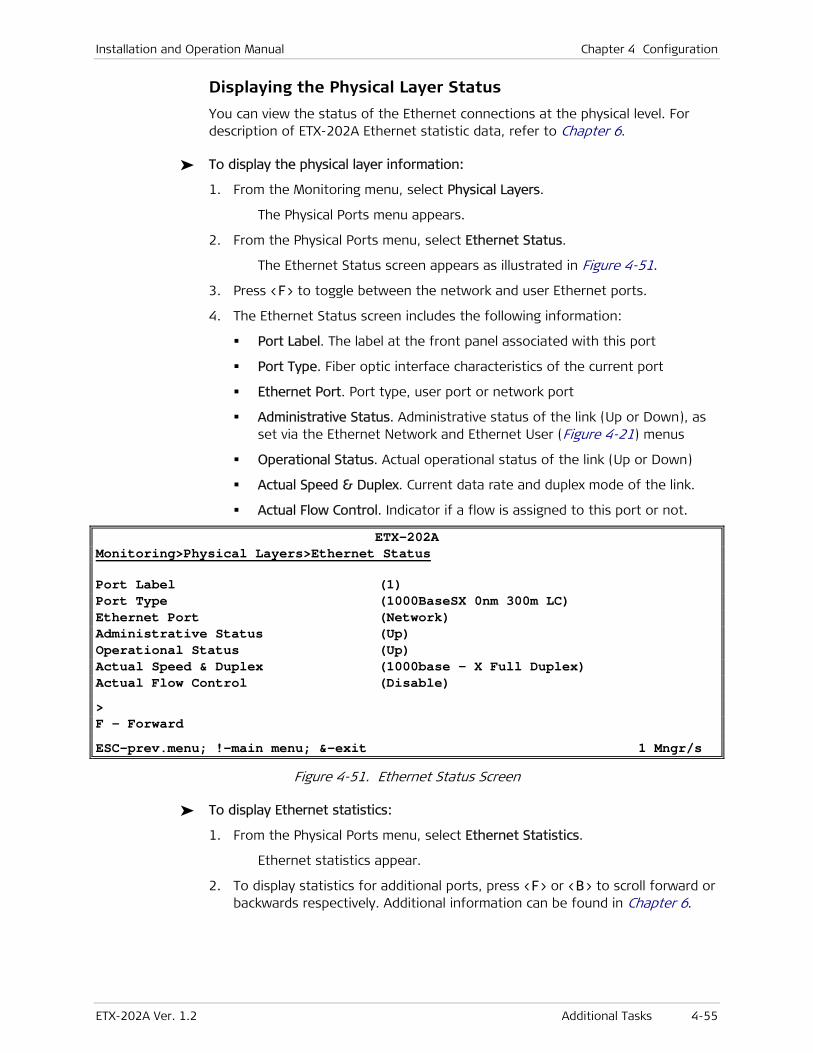
Installation and Operation Manual Chapter 4 Configuration
ETX-202A Ver. 1.2 Additional Tasks 4-55
Displaying the Physical Layer Status
You can view the status of the Ethernet connections at the physical level. For description of ETX-202A Ethernet statistic data, refer to Chapter 6.
To display the physical layer information:
1. From the Monitoring menu, select Physical Layers.
The Physical Ports menu appears.
2. From the Physical Ports menu, select Ethernet Status.
The Ethernet Status screen appears as illustrated in Figure 4-51.
3. Press <F> to toggle between the network and user Ethernet ports.
4. The Ethernet Status screen includes the following information:
Port Label. The label at the front panel associated with this port
Port Type. Fiber optic interface characteristics of the current port
Ethernet Port. Port type, user port or network port
Administrative Status. Administrative status of the link (Up or Down), as set via the Ethernet Network and Ethernet User (Figure 4-21) menus
Operational Status. Actual operational status of the link (Up or Down)
Actual Speed & Duplex. Current data rate and duplex mode of the link.
Actual Flow Control. Indicator if a flow is assigned to this port or not.
ETX-202A Monitoring>Physical Layers>Ethernet Status
Port Label (1) Port Type (1000BaseSX 0nm 300m LC) Ethernet Port (Network) Administrative Status (Up) Operational Status (Up) Actual Speed & Duplex (1000base - X Full Duplex) Actual Flow Control (Disable) > F - Forward ESC-prev.menu; !-main menu; &-exit 1 Mngr/s
Figure 4-51. Ethernet Status Screen
To display Ethernet statistics:
1. From the Physical Ports menu, select Ethernet Statistics.
Ethernet statistics appear.
2. To display statistics for additional ports, press <F> or <B> to scroll forward or backwards respectively. Additional information can be found in Chapter 6.

Chapter 4 Configuration Installation and Operation Manual
4-56 Additional Tasks ETX-202A Ver. 1.2
To display the link status of connected SFPs:
1. From the Physical Ports menu, select SFP, and then Link Status.
The SFP parameters for the current port appear, such as the connector type, the manufacturer name, the serial number and the range.
2. To display the SFP parameters for additional ports port, press <F> or <B> to scroll forward or backwards respectively.
Displaying the Application Status
This section explains how to display the application status.
Displaying the OAM Connection Status
At the connection level ETX-202A provides information on the OAM ID, OAM VLAN and OAM status.
To display the OAM connection status information:
1. From the End-to-End menu (Monitoring > Application > OAM > End-to-End), select Status.
The Connection Status menu appears as illustrated in Figure 4-43.
2. From the End-to-End Status screen press <F> or <B> to toggle between the active OAM flows.
ETX-202A Monitoring>Application>OAM>End-to-End>Status
Flow ID ... (String) Flow SP VLAN[1 – 4094] ... (1) Flow Status > (Not Applicable) 1. Flow[1 – 64] ... (1)
Please select item <1 to 1> F – Forward; B – Backward ESC-prev.menu; !-main menu; &-exit 1 Mngr/s
Figure 4-52. End-to-End Status Screen
Displaying the Link OAM Status
At the link level ETX-202A provides status information according to the IEEE 802.3ah requirements. The 802.3ah link status collection must be enabled at the physical level for each ETX-202A network and user interface.
To display the link’s OAM status:
1. Navigate to Monitoring > Application > OAM > Link (802.3ah).
2. From the Link (802.3ah) menu, select Status.
The Link (802.3ah) Status screen appears.
3. Press <F> to toggle between the network and user Ethernet ports.
The Link (802.3ah) Status screen includes the following information:

Installation and Operation Manual Chapter 4 Configuration
ETX-202A Ver. 1.2 Additional Tasks 4-57
Local OAM Mode. OAM mode of he local unit
Local Discovery State. Detection of an OAM sublayer presence in remote unit.
Remote Revision. Current revision of information TLV.
Remote MAC Addr. MAC address of remote unit
Remote Capabilities. OAM capabilities of remote unit
Vars Retrieval
Link Events
Loopback
Unidirectional
Remote OAM Mode.
ETX-202A Monitoring>OAM>Link (802.3ah)>Status
Port Label > (1) Ethernet Port > (Network 1) Local OAM Mode (Passive) Local Discovery State > (Passive Wait) Remote revision > (0) Remote Mac Addr. (00-00-00-00-00-00) Remote Capabilities Vars Retrieval > (Supported) Link Events > (Supported) Loopback > (Supported) Unidirectional > (Supported) Remote OAM Mode > (Active) F- Forward ESC-prev.menu; !-main menu; &-exit; ?-help
Figure 4-53. Link (802.3ah) Status Screen

Chapter 4 Configuration Installation and Operation Manual
4-58 Additional Tasks ETX-202A Ver. 1.2
Displaying the Data Flow Connection Status
At the application level ETX-202A provides information on the Data Flow ID, Data Flow SP VLAN and number of frames transmitted in upstream and downstream directions.
To display the data flow connection status information:
1. Navigate to Monitoring > Application > OAM > End-to-End.
The OAM End-to-End menu appears.
2. Select Status.
The Status screen appears as illustrated in Figure 4-52.
3. Press <F> or <B> to toggle between the active flows.
ETX-202A Monitoring>Application>OAM>End-to-End
FlowID ... (Put your string here) Flow SP VLAN[1 – 4094] ... (1) Flow Status > (Not Configured) 1. Flow[1 - 64] ... (1)
Please select item <1 to 1> F - Forward; B - Backward ESC-prev.menu; !-main menu; &-exit 1 Mngr/s
Figure 4-54. Data Flows Status Screen

Installation and Operation Manual Chapter 4 Configuration
ETX-202A Ver. 1.2 Additional Tasks 4-59
Setting the Date and Time
You can set the date and time for the ETX-202A internal real-time clock or receive the NTP server clock signal.
To set date and time:
1. From the System menu, select Date/time.
The Date/Time menu appears as illustrated in Figure 4-55.
2. From the Date/Time menu, select Set time, and enter the current time in the hh:mm:ss format.
3. Select Set date, and enter the current date in the yyyy:mm:dd format.
ETX-202A Configuration>System>Date/Time
1. Time <HH:MM:SS> ... (09:12:06) 2. Date <YYYY-MM-DD> ... (2004-01-18) 3. NTP Mode > Please select item <1 to 3> ESC-prev.menu; !-main menu; &-exit 1 Mngr/s
Figure 4-55. Date/Time Menu
Receiving the Clock from the NTP
This section explains how to receive the clock signal from an NTP server in the network. To do so, you have to first enable ETX-202A’s unicast client.
To enable ETX-202A’s unicast NTP client:
1. From the Date/Time menu, select NTP Mode.
NTP mode options appear.
2. Select Unicast Client.
NTP server parameters appear, which must be configured as well to specify the clock server that ETX-202A should synchronize with.
To specify the clock server:
1. Select NTP Server IP Address and then specify the clock server’s IP address.
2. Select GMT (+/- XX).
The GMT (+/- XX) menu appears.
3. Select the deviation of your time zone from Greenwich Main Time (GMT). For additional options, press <N> or <P> respectively.
4. Select NTP Update Interval (Min) and then enter the desired update interval in minutes. You can choose a value between one and 1440 minutes.
When specified, ETX-202A connects to the clock server and re synchronizes with the network time in the specified time intervals.

Chapter 4 Configuration Installation and Operation Manual
4-60 Additional Tasks ETX-202A Ver. 1.2
Configuring User Access
ETX-202A management software allows you to define new users, their management and access rights. Only superusers (su) can create new users, the regular users are limited to changing their current passwords, even if they were given full management and access rights.
To add a new user:
1. Make sure that you logged in as su.
2. From the Management Access menu, select User access.
The User Access menu appears as illustrated in Figure 4-56.
3. From the User Access menu, do the following:
Select User name, and enter a name for a new user.
Select Permission, and specify the user’s access rights (full control or read only).
Select Access, and specify the user’s access methods (ASCII terminal, Telnet, Web browser, Telnet and Web browser, or all of them).
Select ‘su’ password, and enter your current superuser password.
Select New password, and then assign a password to a new user name.
Select Confirm and re-enter the new user password to confirm it.
Save the new settings by pressing <S>, when prompted.
To delete an existing user:
• From the User Access menu, do the following:
Press <F> to display a user that you intend to delete.
Select ‘su’ password, and enter your current superuser password.
Press <D> to delete the current user.
ETX-202A Configuration>System>Management>Management access>User access
1. User name ... (su) 2. Permission > (Full Control) 3. Access > (All) 4. ‘su’ password ... () 5. New password ... () 6. Confirm New Password ... () > Please select item <1 to 6> ESC-prev.menu; !-main menu; &-exit 1 Mngr/s
Figure 4-56. User Access Menu

Installation and Operation Manual Chapter 4 Configuration
ETX-202A Ver. 1.2 Additional Tasks 4-61
Transferring Software and Configuration Files
This section presents procedures for installing new software releases into the ETX-202A units and transferring configuration files.
ETX-202A stores two software versions, each of them in one of the two 1.15 MB partitions of its flash memory, which also contains a boot program. The software is stored in compressed format. The main version is decompressed and loaded into the ETX-202A RAM upon power-up. The backup software is kept for backup purposes. If the main software becomes corrupted, you can swap it with the backup. By default, ETX-202A is delivered with active software only.
New software releases are distributed as *.img files, which are downloaded to ETX-202A. When starting a download, ETX-202A erases the current backup and places the new software in the backup partition. When downloading is complete, the unit checks the integrity of the new software file. If it is correct, the backup and active files are swapped. The new software release becomes active and the former active software becomes the backup. If a failure occurs during downloading, the new version is erased. In this case, only one version is left stored in the flash memory. The backup software can be downloaded to the unit and swapped with the main software later.
Configuration files can be uploaded for storage and backup.
The management software allows file transfer over the network via TFTP. To download software files over a serial connection via XMODEM, you have to use the Boot Manager as explained in Appendix B.
To transfer files via TFTP:
1. From the Main menu, select Utilities.
The Utilities menu appears.
2. From the Utilities menu, select File Utilities.
The File Utilities menu appears.
3. From the File Utilities menu, select S/W & File Transfer using TFTP.
The S/W & File Transfer using TFTP menu appears as illustrated in Figure 4-57.
4. From the S/W & File Transfer using TFTP menu, perform the following:
Select File Name, and enter a file name:
For downloading, you specify name of the file, which is to be downloaded to ETX-202A.
For uploading, you specify a name, under which the file is going to be saved on the remote server.
Select Command to start the desired procedure:
No Operation. TFTP file transfer is disabled.
Software Download. Transferring a software file to ETX-202A.
Software Upload. Saving a software file on a remote server
Configuration Download. Transferring a configuration file to ETX-202A.

Chapter 4 Configuration Installation and Operation Manual
4-62 Additional Tasks ETX-202A Ver. 1.2
Configuration Upload. Saving a configuration file on a remote server
Software Download and Reset. Transferring a software file to ETX-202A and resetting the unit
Software Download to Backup. Transferring a software file to the backup partition of ETX-202A.
Select Server IP and enter the TFTP server’s IP address.
Define the Retry Timeout, the interval between attempts to reconnect (in seconds).
Define the Total Timeout, the TFTP connection timeout (in seconds)
Select Save.
The file transfer starts.
To view the transfer status, select View Transfer Status. Possible status messages are listed below:
TFTP – Starting Upload
TFTP – Starting Download
TFTP – Upload Failed
TFTP – Download Failed.
ETX-202A Utilities>File Utilities>S/W & File Transfer using TFTP
1. File name ... (FILE.IMG) 2. Command > (No operation) 3. Server IP ... (0.0.0.0) 4. Retry timeout(sec)[0 - 1000] ... (1) 5. Total timeout(sec)[0 - 1000] ... (5) 6. View transfer status > > ESC-prev.menu; !-main menu; &-exit 1 Mngr/s
Figure 4-57. S/W & File Transfer using TFTP Menu

Installation and Operation Manual Chapter 4 Configuration
ETX-202A Ver. 1.2 Additional Tasks 4-63
Swapping the Software Files
When the software file is downloaded to the backup partition, it can be swapped with the main software file.
To swap software files:
1. From the File Utilities menu, select Swap Main Application File With Backup.
ETX-202A displays the following message: Backup application file will be active after reset. Continue ??? (Y/N).
2. Press <Y> to complete the swap.
Resetting ETX-202A
ETX-202A supports two types of reset:
• Reset to the default setting
• Overall reset of the device.
Resetting ETX-202A to the Defaults
You can reset ETX-202A to its default settings. All configuration parameters can be reset the their default values, or you can reset ETX-202A without affecting its management settings (host IP address, mask, default gateway and the network managers).
To reset ETX-202A to the default settings:
1. From the System menu, select Factory Default.
The Factory Default menu appears as illustrated in Figure 4-58.
2. From the Factory Default menu, do the following:
Select Full to reset all configuration parameters to their defaults.
Select Except Management Connectivity Parameters to reset all configuration parameters, except for the management settings.
ETX-202A displays the following message: Configuration will be lost and system will be reset. Continue??? (Y/N).
3. Press <Y> to confirm the reset.
ETX-202A restarts and the factory default is restored.
ETX-202A Configuration>System>Factory default
1. Full 2. Except management Connectivity Parameters > ESC-prev.menu; !-main menu; &-exit 1 Mngr/s
Figure 4-58. Factory Default

Chapter 4 Configuration Installation and Operation Manual
4-64 Additional Tasks ETX-202A Ver. 1.2
Resetting ETX-202A
You can perform the overall reset of ETX-202A.
To reset ETX-202A:
1. From the Utilities menu, select Reset.
The following confirmation message appears: System will be reset. Continue??? (Y/N)
2. Press <Y> to confirm your request.
ETX-202A resets.

ETX-202A Ver. 1.2 Configuring a Point-to-Point Application 5-1
Chapter 5
Configuring Typical Applications This chapter provides detailed instructions for setting up typical applications using ETX-202A units. Refer to Chapter 4 for a detailed description of all configuration options available for ETX-202A.
5.1 Configuring a Point-to-Point Application
Figure 5-1 illustrates a point-to-point application of an Ethernet private line over a WAN.
PacketSwitched Network
Network
PacketSwitched Network
User 1 NetworkCPE
CPE
User 2
VLAN 20
VLAN 30
VLAN 220
VLAN 230
User 1
User 2
VLAN 20
VLAN 30
VLAN 220
VLAN 230
WideArea
Network(WAN)ETX-202A (A)
192.168.10.10ETX-202A (B)192.168.10.20
Figure 5-1. Point-to-Point Ethernet Private Line over Wide Area Network
In this application, ETX-202A (A) receives Ethernet user traffic separated by VLAN at both Gigabit Ethernet user ports, and transmits it over separate VLANs through the Wide Area network. ETX-202A (B) receives the user traffic separated by VLAN from the Wide Area network user traffic separated by VLAN, and transmits it via one Gigabit Ethernet user port, separated by VLAN.
You must configure the following to deploy ETX-202A units in this application:
1. System parameters (host IP, default gateway)
2. Flow Interface configuration
3. Flows.
Table 5-1. System Configuration Summary, Point-to-Point Application
Device Host IP IP mask Default Gateway
ETX-202A (A) 192.168.10.10 255.255.255.0 192.168.10.1
ETX-202A (B) 192.168.10.20 255.255.255.0 192.168.10.1

Chapter 5 Configuring Typical Applications Installation and Operation Manual
5-2 Configuring a Point-to-Point Application ETX-202A Ver. 1.2
Table 5-2. Flow Interface Configuration Summary
Flow Interface Flow Key
Gigabit Ethernet 1, ETX-202A (A) SP-VLAN
Gigabit Ethernet 2, ETX-202A (A) SP-VLAN
Gigabit Ethernet 1, ETX-202A (B) SP-VLAN
Table 5-3. Flow Configuration Summary, ETX-202A (A)
Flow Interface Flow ID CE-VLAN-ID Flow Interface SP-VLAN-ID
Gigabit Ethernet 1 1 20 User 1 220
Gigabit Ethernet 2 2 30 User 1 230
Table 5-4. Flow Configuration Summary, ETX-202A (B)
Flow Interface Flow ID CE-VLAN-ID Flow Interface SP-VLAN-ID
Gigabit Ethernet-1 1 20 User 2 220
Gigabit Ethernet-2 2 30 User 2 230
Configuring System Parameters
The configuration procedure for system parameters is similar for both ETX-202A units, except for defining different host IP addresses. Refer to Chapter 3 for an explanation of how to select management options and save the changes.
To configure the host parameters:
• Display the Host menu (Configuration> System > Host), and configure the host parameters as listed in Table 5-1.
ETX-202A Configuration>System>Host
1. IP Address ... (192.168.10.10) 2. IP Mask ... (255.255.255.0) 3. Default Gateway ... (192.168.10.1) 4. DHCP ... (Disable) 5. Default IP ... (0.0.0.0) 6. DHCP Status > ESC-prev.menu; !-main menu; &-exit 1 Mngr/s
Figure 5-2. Configuring Host Parameters for ETX-202A (A), Point-to-Point Application
Configuring Flow Interfaces
The flow interface configuration procedure is similar for the Gigabit Ethernet bridge ports in both ETX-202A units. You must configure the flow interfaces as detailed in Table 5-1.

Installation and Operation Manual Chapter 5 Configuring Typical Applications
ETX-202A Ver. 1.2 Configuring a Point-to-Point Application 5-3
To configure the flow interfaces on the network side:
1. From the Flow Interface menu (Configuration > Application > Flows > Flow Interface), press <F> to select the first Gigabit Ethernet port of ETX-202A (A). It is labeled Network 1.
2. Select CoS Profile and set it to NetworksCosPbits.
3. Select Flow Key and set it to SP-VLAN.
4. Perform steps 2 through 4 for the second Gigabit Ethernet port of ETX-202A (A) and the first Gigabit Ethernet port of ETX-202A (B).
ETX-202A Configuration>Applications>Flows>Flow Interface
Port Label > (1) Bridge Port > (Network 1)
1. Flow Key > (SP-VLAN ID) 2. CoS Profile > (UsersCosPbits) 3. SP Tag Protocol Identifier[0 - ffff] ... (8100) 4. Egress MTU[15 - 15984] ... (1790) 5. L2CP Handling > 6. Scheduler Profile > (Default Queue Group) Please select item <1 to 6> F - Forward ESC-Previous menu; !-Main menu; &-Exit
Figure 5-3. Configuring Flow Interface - Network Port
To configure the flow interfaces on the user side:
1. From the Flow Interface Port menu (Configuration > Application > Flows > Flow Interface), press <F> to select the third port of ETX-202A (A). It is labeled User 1.
2. Select CoS Profile and set it to UsersCosPbits.
3. Select Flow Key and set it to CE-VLAN ID.
4. Perform steps 2 through 4 for the remaining user ports of ETX-202A (A) and the ones of ETX-202A (B).

Chapter 5 Configuring Typical Applications Installation and Operation Manual
5-4 Configuring a Point-to-Point Application ETX-202A Ver. 1.2
ETX-202A Configuration>Applications>Flows>Flow Interface
Port Label > (3) Bridge Port > (User 1) 1. Accept Frame Type (All) 2. Flow Key > (CE-VLAN ID) 3. CoS Profile > (UsersCosPbits) 4. Untagged Frames Handling (Add CE-VLAN Tag) 5. Default VID[1 - 4094] ... (1) 6. Default 802.1p[0 - 7] ... (0) 7. Egress MTU[64 - 15984] ... (1790) 8. L2CP Handling > 9. Marking Profile > (Marking1) 10. Scheduler Profile > (test) Please select item <1 to 10> F - Forward ESC-Previous menu; !-Main menu; &-Exit
Figure 5-4. Configuring Flow Interface – User Port
Configuring the Flows
In ETX-202A (A), you have to configure a flow for each Gigabit Ethernet port, with CE VLAN and SP VLAN memberships as illustrated in Table 5-3. In ETX-202A (B), you have to configure two flows for one Gigabit Ethernet port, with CE VLAN and SP VLAN memberships as illustrated in Table 5-4.
Configuring Flows in ETX-202A (A)
To configure flow 1 in ETX-202A (A):
1. From the Flow Definition menu (Configuration > Application > Flows > Flow Definition), press <A> to add a flow.
2. Select Flow Name and assign a name to the flow (alphanumeric string of up to 70 characters), for example GbE-1 A.

Installation and Operation Manual Chapter 5 Configuring Typical Applications
ETX-202A Ver. 1.2 Configuring a Point-to-Point Application 5-5
ETX-202A Configuration>Application>Flows>Flow Definition
1. Flow ID[1 - 30] ... (1) 2. Flow Name ... (GbE-1 A) Queue Group Profile ... (Default Queue Group) 3. Bind to Queue Block > (QueueGroup1) 4. Flow Interface List > Please select item <1 to 4> A-Add New Flow; F-Forward ; B-Backward ; D-Delete ESC-prev.menu; !-main menu; &-exit 1 Mngr/s
Figure 5-5. Configuring Flow 1, ETX-202A (A)
3. Select Flow Interface List to display the Flow Interface List menu.
The Flow Interface List menu appears.
ETX-202A Configuration>Application>Flows>Flow Definition>Flow Interface List
Flow ID (1) Port Label > (1) Flow Interface > (Network 1)
1. SP Tag Handling (Stack) 2. SP-VLAN (220) Please select item <1 to 2> A-Add New Bridge Port F-Forward ESC-prev.menu; !-main menu; &-exit 1 Mngr/s
Figure 5-6. Flow Bridge Port GbE-1
4. Select SP Tag Handling and set it to Stack.
5. Select SP-VLAN and set it to 220.
6. Press <A> to add a new bridge port and then select User 1.
The Bridge Port List menu appears as illustrated in Figure 5-7.

Chapter 5 Configuring Typical Applications Installation and Operation Manual
5-6 Configuring a Point-to-Point Application ETX-202A Ver. 1.2
ETX-202A Configuration>Applications>Flows>Flow Definition>Flow Interface List
Flow ID[1 - 30] ... (1) Port Label > (3) Flow Interface > (User 1)
1. Mapping > 2. CoS method (By profile) 3. Marking method (By profile) 4. Default Ingress BW Profile > (Profile1) 5. Service Frames Type > (All) 6. CE VLAN Egress Action > (Maintain) 7. CoS > > Please select item <1 to 4> F-Forward ESC-prev.menu; !-main menu; &-exit 1 Mngr/s
Figure 5-7. Flow Bridge Port GbE-1
7. Select Mapping.
8. From the Mapping menu, select Mapping Mode and set it to User Mapping.
ETX-202A Configuration>Application>Flows>Flow Definition>Flow Interface List >Mapping ( CE-VLAN ID )
Flow ID … (1) Port Label (3) Bridge Port (User 1)
1. Mapping Mode (User Mapping) 2. CE-VLAN ID Members > (20) Please select item <1 to 4> A-Add ESC-prev.menu; !-main menu; &-exit 1 Mngr/s
Figure 5-8. Flow Mapping for GbE-1 of ETX-202A (A)
9. Select CE-VLAN ID Members and add 20 as a member.
10. Save your changes.

Installation and Operation Manual Chapter 5 Configuring Typical Applications
ETX-202A Ver. 1.2 Configuring a Point-to-Point Application 5-7
To configure flow 2 in ETX-202A (A):
1. From the Flow Definition menu (Configuration > Application > Flows > Flow Definition), press <A> to add a flow.
2. Select Flow Name and assign a name to the flow (alphanumeric string of up to 70 characters), for example GbE-2 A.
ETX-202A Configuration>Application>Flows>Flow Definition
1. Flow ID[1 - 30] ... (2) 2. Flow Name ... (GbE-2 A) Scheduler Profile ... (Default Queue Group) 3. Bind to Queue Group > (QueueGroup1) 4. Flow Interface List > Please select item <1 to 4> A-Add New Flow; F-Forward ; B-Backward ; D-Delete ESC-prev.menu; !-main menu; &-exit 1 Mngr/s
Figure 5-9. Configuring Flow 2, ETX-202A (A)
3. Select Flow Interface List to display the Flow Interface List menu.
The Flow Interface List menu appears.
ETX-202A Configuration>Application>Flows>Bridge Port List
Flow ID (2) Port Label > (2) Flow Interface > (Network 2)
1. SP Tag Handling (Stack) 2. SP-VLAN (230) > Please select item <1 to 2> A-Add New Bridge Port F-Forward ESC-prev.menu; !-main menu; &-exit 1 Mngr/s
Figure 5-10. Flow Bridge Port GbE-2
4. Select SP Tag Handling and set it to Stack.
5. Select SP-VLAN and set it to 230.
6. Press <A> to add a new bridge port and then select User 2.
The Bridge Port List menu appears as illustrated in Figure 5-7.

Chapter 5 Configuring Typical Applications Installation and Operation Manual
5-8 Configuring a Point-to-Point Application ETX-202A Ver. 1.2
ETX-202A Configuration>Applications>Flows>Flow Definition>Flow Interface List
Flow ID[1 - 30] ... (2) Port Label > (3) Flow Interface > (User 2)
1. Mapping > 2. CoS method (By profile) 3. Marking method (By profile) 4. Default Ingress BW Profile > (Profile1) 5. Service Frames Type > (All) 6. CE VLAN Egress Action > (Maintain) 7. CoS > > Please select item <1 to 4> F-Forward ESC-prev.menu; !-main menu; &-exit 1 Mngr/s
Figure 5-11. Flow Bridge Port GbE-2
7. Select Mapping.
8. From the Mapping menu, select Mapping Mode and set it to User Mapping.
ETX-202A Configuration>Application>Flows>Flow Definition>Flow Interface List >Mapping ( CE-VLAN ID )
Flow ID … (2) Port Label (3) Bridge Port (User 2)
1. Mapping Mode (User Mapping) 2. CE-VLAN ID Members > (30) > Please select item <1 to 4> ESC-prev.menu; !-main menu; &-exit 1 Mngr/s
Figure 5-12. Flow Mapping for GbE-2 of ETX-202A (A)
9. Select CE-VLAN ID Members and add 30 as a member.
10. Save your changes.

Installation and Operation Manual Chapter 5 Configuring Typical Applications
ETX-202A Ver. 1.2 Configuring a Point-to-Point Application 5-9
Configuring Flows in ETX-202A (B)
To configure flows 1 and 2 in ETX-202A (B):
1. From the Flow Definition menu (Configuration > Application > Flows > Flow Definition), press <A> to add a flow.
2. Select Flow Name and assign a name to the flow (alphanumeric string of up to 70 characters), for example GbE-1 B.
3. Add the flows to ETX-202A (B) as explained for ETX-202A (A).

Chapter 5 Configuring Typical Applications Installation and Operation Manual
5-10 Configuring a Point-to-Point Application ETX-202A Ver. 1.2

ETX-202A Ver. 1.2 Monitoring Performance 6-1
Chapter 6
Troubleshooting and Diagnostics This chapter describes how to:
• Display system messages
• Monitor performance
• Run diagnostic tests.
6.1 Monitoring Performance
Performance monitoring data is collected at:
• Ethernet physical layer
• End-to-End OAM/CFM OAM
• Flow
Displaying End-to-End Statistics
You can display end-to-end connectivity and performance monitoring data for the existing flows and its services. The statistics are available for the 15-minute and 24-hour periods.
To display the OAM statistics:
1. From the End-To-End menu (Monitoring > Application > OAM > End-to-End), select Statistics.
The Statistics menu is displayed.
2. From the Statistics menu, select the following:
15 Min Intervals (OAM statistics for a selected 15-min interval)
24 Hours Counters (OAM statistics for the last 24 hours)
Service Counters (Total OAM statistics collected since the service was enabled)
The selected OAM Statistics screen is displayed as illustrated in Figure 6-1 and Figure 6-2. Table 6-1 and Table 6-2 explain the OAM statistics parameters.

Chapter 6 Troubleshooting and Diagnostics Installation and Operation Manual
6-2 Monitoring Performance ETX-202A Ver. 1.2
3. To select a flow, press <F> or <B> to navigate to the desired flow or select Flow and enter the desired flow’s ID.
4. Press <Ctrl + F> or <Ctrl + B> to select an interval (1–96).
No interval selection is available for the 24-hour statistics.
ETX-202A Monitoring>Application>OAM>End-To-End>Statistics>15 Min. Intervals
Frames Above Delay Obj.... (0) Elapsed Time ... (102767) Frames Below Delay Obj.... (0) Frames Above DV Obj. ... (0) Min. RT Delay (Msec) ... (0.0) Frames Below DV Obj. ... (0) Avg. RT Delay (Msec) ... (0.0) Frames Transmitted ... (101902) Max. RT Delay (Msec) ... (0.0) Frames Lost ... (0) Unavailable Seconds ... (101899) Avg. DV ... (0.0) Max. DV ... (0.0) 1. Interval ... (0) 2. Flow [1 - 64] ... (1) 3. Service [1 - 3] ... (1) Please select item <1 to 3> F - Forward(SVC); B - Backward(SVC); ^F - Forward(Int.); ^B - Backward(Int.) ESC-prev.menu; !-main menu; &-exit 1 Mngr/s
Figure 6-1. End-to-End Statistics (15-Minute Interval)
Table 6-1. OAM Statistic Parameters
Parameter Description
Frames Above Delay Obj. Number of frames that exceeded delay objective
Frames Below Delay Obj. Number of frames below or equal delay objective
Frames Above DV Obj. Number of frames that exceeded delay variation objective
Frames Below DV Obj. Number of frames below or equal delay variation objective
Frames Transmitted Total number of OAM frames transmitted in the selected interval
Frames Lost Number of frames lost in the selected interval
Unavailable Seconds Number of seconds during which the service was unavailable in the current
interval
Elapsed Time Time (in seconds) elapsed from beginning of the interval 0–900
Min. RT Delay Minimum round trip delay (in mseconds) calculated in the interval (or up to
elapsed time in selected interval)
Avg. RT Delay Average round trip delay (in mseconds) calculated in the interval (or up to
elapsed time in current interval)
Max. RT Delay Maximum round trip delay (in mseconds) calculated in the interval (or up
to elapsed time in current interval)
Avg. DV Average delay variation (in mseconds) calculated in the interval (or up to
Note

ETX-202A Installation and Operation Manual Chapter 6 Troubleshooting and Diagnostics
ETX-202A Ver. 1.2 Monitoring Performance 6-3
Parameter Description
elapsed time in selected interval)
Max. DV Maximum delay variation (in mseconds) calculated in the interval (or up to
elapsed time in selected interval)
ETX-202A Monitoring>Application>OAM>End-To-End>Statistics>Service Counters
Flow ... (1) Service ... (1)
OAM Tx frames counter ... (2087328632) OAM Frames lost counter ... (0 OAM Frame loss Ratio ... (0) Elapsed time ... (1487) Unavailable seconds ... (0) Unavailability Ratio ... (0) Current Delay (msec) ... (0.0) Current Delay Variation (msec) ... (0.0)
1. Flow [1 – 64] ... (1) 2. Service [1 – 3] ... (1) Please select item <1 to 2> F - Forward(Flow); B - Backward(Flow) ESC-prev.menu; !-main menu; &-exit 1 Mngr/s
Figure 6-2. End-to-End Service Counters
Table 6-2. Service OAM Statistic Parameters
Parameter Description
OAM Tx Frames Counter Total number of OAM frames transmitted since the service was
enabled
OAM Frames Lost Counter Total number of OAM frames lost since the service was enabled
OAM Frame Loss Ratio Total number of lost OAM frames divided by total number of
transmitted OAM frames since the service was enabled
Elapsed Time Time (in seconds) elapsed since the service was enabled
Unavailable Seconds Total number of unavailable seconds since the service was enabled
Unavailability Ratio Total number of unavailable seconds divided by elapsed time
Current Delay Delay of OAM frames (in msec)
Current Delay Variation Delay variation (in msec)
Displaying Ethernet Status and Statistics
You can display data for the network and user Ethernet ports at the physical layer.

Chapter 6 Troubleshooting and Diagnostics Installation and Operation Manual
6-4 Monitoring Performance ETX-202A Ver. 1.2
To display the Ethernet status:
1. From the Physical Layers menu, select Ethernet Status.
The Ethernet Status screen appears as illustrated in Figure 6-4.
2. Press <F> to toggle between network and user interface status screens.
ETX-202A
Monitoring>Physical Layers>Ethernet Status
Port Label (3) Port Type (1000BaseT RJ45) Administrative Status (Up) Operational Status > (Down) Actual Speed & Duplex > (10Mbps – Full Duplex) F – Forward ESC-prev.menu; !-main menu; &-exit 1 Mngr/s
Figure 6-3. Ethernet Statistic
To display the Ethernet statistics:
1. From the Physical Layers menu, select Ethernet Statistics.
The Ethernet Statistics screen appears as illustrated in Figure 6-4.
2. Press <F> to toggle between network and user interface statistics. Table 6-3 describes the Ethernet statistic registers.
3. Press <C> to reset the counters.
4. Press <R> to refresh the screen.
ETX-202A
Monitoring>Physical Layers>Ethernet Statistics
Port Label (1) Ethernet Port (Network 1)
Counter --- RX --- --- TX --- Total Frames (0) (2123) FCS Errors (0) F – Forward; C – Clear Statistics; R – Refresh Statistics ESC-prev.menu; !-main menu; &-exit 1 Mngr/s
Figure 6-4. Ethernet Statistics
Table 6-3. Ethernet Statistics Parameters
Parameter Description
RX
Total Frames The total number of correct frames received
FCS Errors Total number of frames received on a particular interface that is an integral
number of octets in length, but do not pass the FCS check. This count does not
include frames received with Frame-Too-Long or Frame-Too-Short error.

ETX-202A Installation and Operation Manual Chapter 6 Troubleshooting and Diagnostics
ETX-202A Ver. 1.2 Handling Events and Traps 6-5
6.2 Handling Events and Traps
ETX-202A maintains a log file, which can hold up to 2084 events (system messages). All events are time-stamped.
Displaying Events
To access the event log:
1. From the Event Log menu (Monitoring > System > Event Log), select Read Log File.
The Event Log appears as illustrated in Figure 6-5. Table 6-4 presents the event types that appear in the event log.
2. In the Event Log screen, press <Ctrl + U> and <Ctrl + D> keys to scroll the alarm list up and down.
ETX-202A Monitoring>System>Event Log>Read Log File
Log Entry 1 2005-03-16 19:50:08 LOGIN VIA TERMINAL 2 2005-03-16 19:22:32 LOGIN VIA TERMINAL | 3 2005-03-16 19:22:13 LINK DOWN PORT 5 v 4 2005-03-16 19:22:12 LINK DOWN PORT 4 5 2005-03-16 19:22:12 LINK DOWN PORT 3 6 2005-03-16 19:22:12 LINK DOWN PORT 2 7 2005-03-16 19:22:12 LINK DOWN PORT 1 8 2005-03-16 19:22:11 COLD START ^D - Scroll Down , ^U - Scroll Up ESC-prev.menu; !-main menu; &-exit; ?-help 1 Mngr/s
Figure 6-5. Event Log
Table 6-4. System Events List
System Events Description
COLD START The unit has been restarted
FATAL ERROR XX Hardware failure has been detected
FATAL ERROR AT XX LINE XX Hardware failure has been detected
SYSTEM USER RESET Overall reset was performed by the user
LOG FILE RECOVERED Log file corruption detected and recovered while starting the system
LOGIN VIA (TELNET, WEB,
TERMINAL)
ETX-202A has been accessed via Telnet, Web or the terminal application.
INVALID LOGIN VIA (TELNET,
WEB, TERMINAL)
Invalid user name and/or password has been detected while initializing the
Telnet, Web or terminal management session.

Chapter 6 Troubleshooting and Diagnostics Installation and Operation Manual
6-6 Handling Events and Traps ETX-202A Ver. 1.2
Physical Port Events Description
LINK DOWN PORT X Network or user Ethernet port has been disconnected
LINK UP PORT X Network or user Ethernet port has been connected
LINK ADMIN DOWN PORT X Network or user Ethernet port has been disabled by the user
DHCP Events Description
IP X.X.X.X ASSIGNED BY SERVER
X.X.X.X
IP address X.X.X.X has been assigned by DHCP server X.X.X.X
IP X.X.X.X IS RELEASED IP address X.X.X.X has been released by ETX-202A
CONNECTIVITY MISMATCH EVC X
OFF
No Flow (EVC) ID or MEP ID mismatch has been detected on EVC X
CONNECTIVITY MISMATCH EVC X
ON
Flow (EVC) ID or MEP ID mismatch has been detected on EVC X
CC FAILURE EVC X ON Continuity check on EVC X has failed
CC FAILURE EVC X OFF Continuity check on EVC X has been restored
EFM OAM (802.3ah) Events Description
OAM (802.3ah) REMOTE DYING
GASP PORT X
Dying gasp indication has been received from the remote partner on OAM link
on port X
EFM OAM (802.3ah) Events Description
OAM (802.3ah) CONNECTIVITY
FAIL PORT X ON
OAM connectivity has been lost on port X
OAM (802.3ah) CONNECTIVITY
FAIL PORT X OFF
OAM connectivity has been restored on port X
OAM (802.3ah) REMOTE LINK
FAIL PORT X ON
Indication of the OAM connectivity failure has been received from the remote
partner on OAM link on port X
EFM OAM (802.3ah) Events Description
OAM (802.3ah) REMOTE LINK
FAIL PORT X OFF
Indication of the OAM connectivity recovery has been received from the
remote partner on OAM link on port X
OAM (802.3ah) REMOTE
CRITICAL ERRORS PORT X ON
Indication of the critical errors has been received from the remote partner on
OAM link on port X
OAM (802.3ah) REMOTE
CRITICAL ERRORS PORT X OFF
Indication of the critical error termination has been received from the remote
partner on OAM link on port X
OAM (802.3ah) REMOTE
LOOPBACK PORT X ON
Indication of the remote loopback activation has been received from the
remote partner on OAM link on port X
OAM (802.3ah) REMOTE
LOOPBACK PORT X OFF
Indication of the remote loopback deactivation has been received from the
remote partner on OAM link on port X

ETX-202A Installation and Operation Manual Chapter 6 Troubleshooting and Diagnostics
ETX-202A Ver. 1.2 Handling Events and Traps 6-7
Table 6-5. Trap List
Trap Description OID Maskable
coldStart The unit has been restarted 1.3.6.1.6.3.1.1.5.1 No
authenticationFailure User authentication has failed 1.3.6.1.6.3.1.1.5.5 No
linkDown Network or user Ethernet port has
been disconnected
1.3.6.1.6.3.1.1.5.3 Yes
linkUp Network or user Ethernet port has
been connected
1.3.6.1.6.3.1.1.5.4 Yes
tftpStatusChangeTrap TFTP session status has changed 1.3.6.1.4.1.164.6.1.0.1 No
agnStatusChangeTrap SNMP agent status has changed 1.3.6.1.4.1.164.6.1.0.2 No
agnPowerFailureTrap ETX-202A power supply is about
to fail
1.3.6.1.4.1.164.6.1.0.13 No
successfulLogin Successful login to
ETX-202A has been detected
1.3.6.1.4.1.164.6.1.0.24 Yes
failedLogin Failed login to ETX-202A has been
detected
1.3.6.1.4.1.164.6.1.0.25 Yes
prtStatusChangeTrap An SFP has been removed from
one of the ports
1.3.6.1.4.1.164.6.1.0.3 No
Clearing Events
To clear the event log:
• From the Event Log menu (Monitoring > System > Event Log), select Clear Log File.
All events are deleted from the log.

Chapter 6 Troubleshooting and Diagnostics Installation and Operation Manual
6-8 Testing ETX-202A ETX-202A Ver. 1.2
Masking Alarm Traps
You can mask some ETX-202A alarm traps to prevent it from being sent to the management stations.
To mask alarm traps:
1. From the Management menu, select Alarm trap mask.
The Alarm Trap Mask menu appears as illustrated in Figure 6-6.
2. From the Alarm Traps Mask menu, select Alarm ID to choose a maskable trap that you intend to mask. Refer to Table 6-5.
A list of the alarm traps can be displayed by pressing <?> for help.
3. Select Trap Status to enable or disable masking of the selected alarm trap.
ETX-202A Configuration>System>Management>Alarm trap mask
Active alarm traps: > (-)
Alarm ID <use 'help'> ... (1) 1. Trap status (Active) Please select item <1 to 2> ? - Help ESC-prev.menu; !-main menu; &-exit 1 Mngr/s
Figure 6-6. Alarm Trap Mask Menu
6.3 Testing ETX-202A
ETX-202A checks network integrity by running ping or trace route tests. In addition, the user can close loopbacks on the switch ports, run a cable integrity and VLAN test.
Running a Ping Test
You can ping a remote IP host to check the ETX-202A IP connectivity with that host.
To ping an IP host:
1. From the Main menu, select Diagnostics.
The Diagnostics menu appears.
2. From the Diagnostics menu, select Ping.
The Ping menu appears as illustrated in Figure 6-7.
3. From the Ping menu, configure the following:
Note
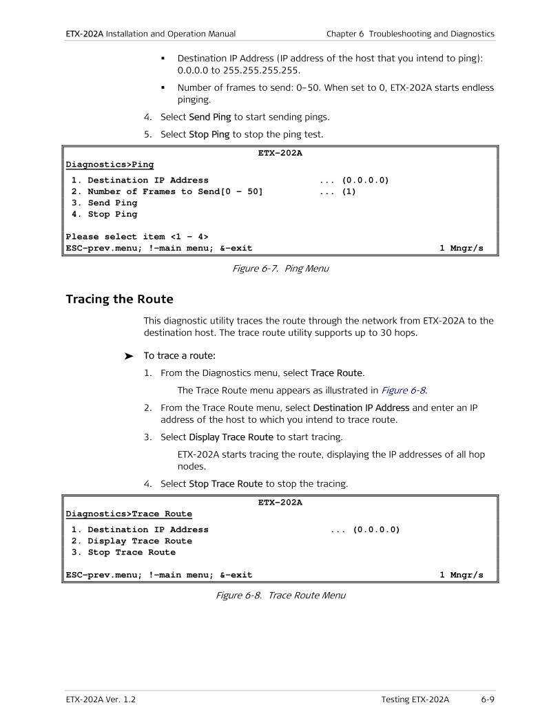
ETX-202A Installation and Operation Manual Chapter 6 Troubleshooting and Diagnostics
ETX-202A Ver. 1.2 Testing ETX-202A 6-9
Destination IP Address (IP address of the host that you intend to ping): 0.0.0.0 to 255.255.255.255.
Number of frames to send: 0–50. When set to 0, ETX-202A starts endless pinging.
4. Select Send Ping to start sending pings.
5. Select Stop Ping to stop the ping test.
ETX-202A Diagnostics>Ping
1. Destination IP Address ... (0.0.0.0) 2. Number of Frames to Send[0 - 50] ... (1) 3. Send Ping 4. Stop Ping Please select item <1 – 4> ESC-prev.menu; !-main menu; &-exit 1 Mngr/s
Figure 6-7. Ping Menu
Tracing the Route
This diagnostic utility traces the route through the network from ETX-202A to the destination host. The trace route utility supports up to 30 hops.
To trace a route:
1. From the Diagnostics menu, select Trace Route.
The Trace Route menu appears as illustrated in Figure 6-8.
2. From the Trace Route menu, select Destination IP Address and enter an IP address of the host to which you intend to trace route.
3. Select Display Trace Route to start tracing.
ETX-202A starts tracing the route, displaying the IP addresses of all hop nodes.
4. Select Stop Trace Route to stop the tracing.
ETX-202A Diagnostics>Trace Route
1. Destination IP Address ... (0.0.0.0) 2. Display Trace Route 3. Stop Trace Route ESC-prev.menu; !-main menu; &-exit 1 Mngr/s
Figure 6-8. Trace Route Menu

Chapter 6 Troubleshooting and Diagnostics Installation and Operation Manual
6-10 Testing ETX-202A ETX-202A Ver. 1.2
Running Loopbacks
ETX-202A supports two loopback types:
• Physical Layer Loopback. It runs at the PHY of the bridge ports. When the loopback is active the data forwarded to a bridge port is looped from the Tx path to the Rx path.
• Application Layer Loopback. You may run Application Layer Loopbacks on the Bridge (UNI) port or on a flow. MAC Swap loopback support exchange source and destination MAC addresses of incoming packets. The user can define the loopback direction (ingress or egress) and the type of data to be looped back. This applies to all data except for packets with management VLAN tag or only packets with a specific VLAN tag.
To run a Physical Layer loopback:
1. Navigate to the Loopback menu (Diagnostics>Loopback).
The Loopback menu appears.
2. From the Loopback menu, select Physical Layer.
The Physical Layer menu appears as illustrated in Figure 6-9.
ETX-202A Diagnostics>Loopbacks>Physical Layer
Port Label (1) Port (Network 1)
1. Direction (Remote) 2. Loopback Timeout(sec)[0 – 3600] (0) 3. Loopback State (Disable) Please select item <1 to 3> F – Forward S - Save ESC-prev.menu; !-main menu; &-exit 1 Mngr/s
Figure 6-9. Running a Phyical Layer Loopback
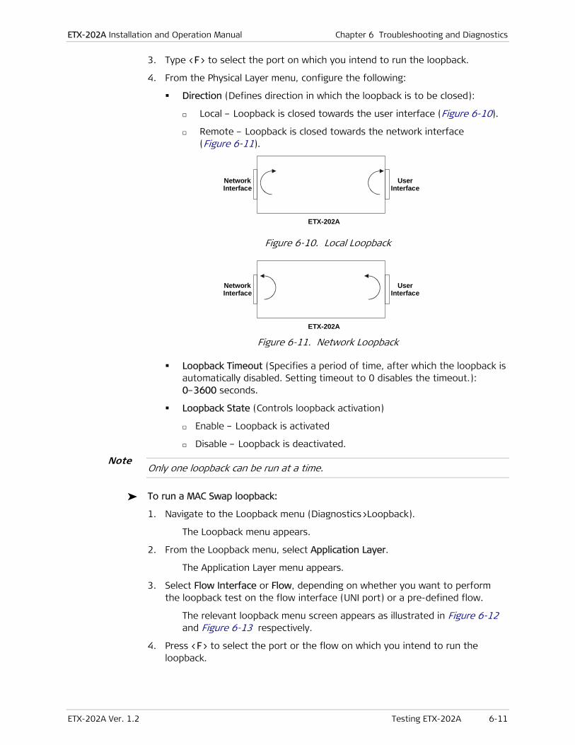
ETX-202A Installation and Operation Manual Chapter 6 Troubleshooting and Diagnostics
ETX-202A Ver. 1.2 Testing ETX-202A 6-11
3. Type <F> to select the port on which you intend to run the loopback.
4. From the Physical Layer menu, configure the following:
Direction (Defines direction in which the loopback is to be closed):
Local – Loopback is closed towards the user interface (Figure 6-10).
Remote – Loopback is closed towards the network interface (Figure 6-11).
ETX-202A
NetworkInterface
UserInterface
Figure 6-10. Local Loopback
ETX-202A
NetworkInterface
UserInterface
Figure 6-11. Network Loopback
Loopback Timeout (Specifies a period of time, after which the loopback is automatically disabled. Setting timeout to 0 disables the timeout.): 0–3600 seconds.
Loopback State (Controls loopback activation)
Enable – Loopback is activated
Disable – Loopback is deactivated.
Only one loopback can be run at a time.
To run a MAC Swap loopback:
1. Navigate to the Loopback menu (Diagnostics>Loopback).
The Loopback menu appears.
2. From the Loopback menu, select Application Layer.
The Application Layer menu appears.
3. Select Flow Interface or Flow, depending on whether you want to perform the loopback test on the flow interface (UNI port) or a pre-defined flow.
The relevant loopback menu screen appears as illustrated in Figure 6-12 and Figure 6-13 respectively.
4. Press <F> to select the port or the flow on which you intend to run the loopback.
Note

Chapter 6 Troubleshooting and Diagnostics Installation and Operation Manual
6-12 Testing ETX-202A ETX-202A Ver. 1.2
ETX-202A Diagnostics>Loopback>Application Layer>Flow Interface
Port Label (5) Port (User 3)
1. Direction (Remote) 2. MAC Swap (Disable) 3. Forced Source Mac ... (00-00-00-00-00-00) 4. Forced Destination Mac ... (00-00-00-00-00-00) 5. Looped Data (All Except MNG) 6. Loopback Timeout (sec) [0-3600] ... (0) 7. Loopback State (Disable) Please select item <1 to 7> F – Forward; S - Save ESC-prev.menu; !-main menu; &-exit 1 Mngr/s
Figure 6-12. Loopbacks Menu (Flow Interface) ETX-202A
Diagnostics>Loopback>Application Layer>Flow Flow Name (1) 1. Flow ID[1 – 30] (1) 2. Direction (Remote) 3. MAC Swap (Enable) 4. Forced Source Mac ... (00-00-00-00-00-00) 5. Forced Destination Mac ... (00-00-00-00-00-00) 6. Looped Data (All Except MNG) 7. Loopback Timeout (sec) [0-3600] ... (0) 8. Loopback State (Disable) > Please select item <1 to 8> F – Forward; S - Save ESC-prev.menu; !-main menu; &-exit 1 Mngr/s
Figure 6-13. Loopbacks Menu (Flow)

ETX-202A Installation and Operation Manual Chapter 6 Troubleshooting and Diagnostics
ETX-202A Ver. 1.2 Testing ETX-202A 6-13
5. From the Loopbacks menu, configure the following:
Direction (Defines direction in which the loopback is to be closed):
Local – Loopback is closed towards the user interface (Figure 6-10).
Remote – Loopback is closed towards the network interface (Figure 6-11).
The following MAC Swap loopbacks cannot be activated:
When the Tag Handling is set to Stack: Specific VLAN local and specific VLAN remote loopbacks on user ports, specific VLAN local loopback on network port
When the VLAN mode is set to VLAN-aware: Specific VLAN remote loopback on network port, specific VLAN local loopback on user ports
When the VLAN mode is set to VLAN-unaware and Host Tagging – to Untagged: specific VLAN local loopback on user ports
MAC Swap (Enables or disables exchanging source and destination MAC addresses:
Enable – MAC address swap is enabled
Disable – MAC address swap is disabled
Forced Source MAC (A MAC address to be used instead of the original source MAC address)
Forced Destination MAC (A MAC address to be used instead of the original destination MAC address)
State (Controls loopback activation)
Enable – Loopback is activated
Disable – Loopback is deactivated.
Looped Data (Defines which data will be looped back):
All – All packets are looped back.
All Except MNG – All packets, excluding the ones with management VLAN tag, are looped back. The management traffic remains intact.
Loopback Timeout (Specifies a period of time, after which the loopback is automatically disabled. Setting timeout to 0 disables the timeout.): 0–3600 seconds.
Loopback State (Controls loopback activation)
Enable – Loopback is activated
Disable – Loopback is deactivated.
• Only one loopback can be run at a time.
• MAC Swap loopback cannot be run on network port 2.
Note

Chapter 6 Troubleshooting and Diagnostics Installation and Operation Manual
6-14 Technical Support ETX-202A Ver. 1.2
6.4 Technical Support
Technical support for this product can be obtained from the local distributor from whom it was purchased.
For further information, please contact the RAD distributor nearest you or one of RAD's offices worldwide. This information can be found at www.rad.com (offices – About RAD > Worldwide Offices; distributors – Where to Buy > End Users).

ETX-202A Ver. 1.2 2BCONTROL Connector A-1
Appendix A
Connector Wiring
A.1 10/100/1000BaseT Connector
The Ethernet electrical interface (10/100/1000BaseT) terminates in 8-pin RJ-45 connectors, wired in accordance with Table A-1. The 10/100/1000BaseT connector supports both MDI and MDIX modes.
Table A-1. 10/100/1000BaseT Connector Pinout
Pin MDI MDIX
1 A+ B+
2 A- B-
3 B+ A+
4 C+ D+
5 C- D-
6 B- A-
7 D+ C+
8 D- C-
A.2 CONTROL Connector
The control terminal interface terminates in a V.24/RS-232 9-pin D-type female DCE connector. Table A-2 lists the CONTROL connector pin assignments.
Table A-2. CONTROL Connector Pinout
Pin Function
1 –
2 Transmit Data (output)
3 Receive Data (input)
4, 5, 6,
7, 8, 9
–

Appendix A Connector Wiring Installation and Operation Manual
A-2 2BCONTROL Connector ETX-202A Ver. 1.2

ETX-202A Ver. 1.2 Booting ETX-202A B-1
Appendix B
Boot Manager
This appendix provides a description of the ETX-202A boot procedure via an ASCII terminal for downloading software.
The ETX-202A software resides in two sections of the flash memory, the boot sector and the file system. The boot sector holds a boot program that calls the rest of the program from the file system.
The file system can hold two compressed copies of the ETX-202A code. One copy is called the operating application, and the other one is called the backup application respectively. The operating file is the default-executable ETX-202A code. The backup file is used whenever the operating file is absent or corrupted.
B.1 Booting ETX-202A
ETX-202A boots up automatically. After powering up, no user intervention is required, except when the user wants to access the file system to modify or update the software or the ETX-202A configuration.
Accessing the Boot Manager
The Boot Manager menu is an option that allows you to perform basic file transfer operations. These operations are all optional.
To access the Boot Manager menu:
1. Make sure that you are logged on to ETX-202A as super user.
2. Restart ETX-202A and keep the terminal application open.
3. Immediately press <Enter> several times.
The Boot Manager menu appears as illustrated in Figure B-1.

Appendix B Boot Manager Installation and Operation Manual
B-2 Booting ETX-202A ETX-202A Ver. 1.2
RAD ETX_202A Boot Version 1.00 (Apr 9 2004) RAD Boot Manager Version 7.01 (Nov 9 2004) 0 - Exit Boot-Manager 1 - Dir 2 - Set Active Software Copy 3 - Delete Software Copy 4 - Download Files or an Application by XMODEM 5 - Format flash 6 - Show basic hardware information 7 - Reset board 8 - System Configuration. 9 - Download an Application by TFTP Press the ESC key to go back to the Main Menu. Select:
Figure B-1. Boot Manager Menu
The Boot manager menu allows you to do the following:
• Dir. Listing all files stored in the flash memory.
• Set Active Software Copy. Swapping operating and backup partitions, thus activating the application stored in the backup partition.
• Delete Software Copy. Deleting the application in the operating partition; the application stored in the backup partition becomes the operating file.
• Download Files or an Application by XMODEM. Downloading a new application (using XMODEM) over the serial connection; the current operating file is saved as the backup file.
• Format flash. Formatting the flash memory; application and configuration files are deleted.
• Show basic hardware information. Displaying basic hardware information (RAM, ROM size etc)
• Reset board. Resetting ETX-202A’s mother board.
• System Configuration. Configuring the ETX-202A IP address, IP mask and default gateway for downloading files using TFTP.
• Download an Application by TFTP. Downloading a new application (using TFTP) over the network; the current operating file is saved as the backup file
If you choose to exchange or delete a file, you will have to confirm your request when prompted.

Installation and Operation Manual Appendix B Boot Manager
ETX-202A Ver. 1.2 Transferring Software Files B-3
B.2 Transferring Software Files
New software releases are distributed as image files transferred to ETX-202A from the Boot Manager menu using the XMODEM or the TFTP protocol. Alternatively, you can download a new software release via TFTP, when the ETX-202A management software is already running (Main menu > Utilities > File Utilities).
Downloading Application Files via XMODEM
Downloading application files using the XMODEM protocol is performed from the Boot Manager menu.
To download an application file via XMODEM:
1. Enter the Boot Manager menu as explained under Accessing the Boot Manager.
2. Select Download Files or an Application by XMODEM.
ETX-202A displays the following message: Select Copy number for download ( 0 )
3. Select the backup partition by typing its number, 0 or 1.
ETX-202A responds with the following string: Please start the XMODEM download.
4. In your terminal application, set the transfer protocol to XMODEM and then send the image file to ETX-202A.
Once the downloading is complete, ETX-202A saves the image file as active partition and upgrades ETX-202A. The previously active partition reverts to the backup, and the boot sequence continues normally.
If an error occurs while downloading, the partially downloaded application is erased from the backup partition and only the active partition remains on the flash memory.
Note
Appendix B Boot Manager Installation and Operation Manual
B-4 Transferring Software Files ETX-202A Ver. 1.2
Downloading Application Files via TFTP
To download application file via TFTP:
1. From the Boot Manager menu, select System Configuration.
2. Configure the IP parameters of ETX-202A (IP address, IP mask and default gateway). These parameters are valid only for the TFTP file transfer via the Boot Manager and can be changed later.
3. Reset ETX-202A
4. Start a TFTP application.
5. Set the connection timeout of the TFTP server to more than 30 seconds to prevent ETX-202A from disconnecting while deleting the backup (about 25 seconds).
6. Select a local software release file for downloading.
7. Enter the TFTP server’s IP address.
8. Start downloading.
ETX-202A automatically erases the backup partition, which takes about 25 seconds. Once the downloading is completed, ETX-202A saves the new application as active partition. The previously active partition reverts to the backup partition.

ETX-202A Ver. 1.2 Introduction C-1
Appendix C
Operation, Administration, and Maintenance (OAM) This appendix describes the ETX-202A Ethernet OAM functionality.
C.1 Introduction
Currently ETX-202A supports pre-standard implementation of Ethernet OAM based on Y.1731 and standard implementation based on Y.1731 and IEEE P802.1ag. The pre-standard implementation is only used for performance measurements when using two RAD units working opposite each other or when working against a RAD that runs an older version of RAD’s Ethernet OAM software. This appendix describes the pre-standard implementation. The standard implementation can be found in the standards Y.1731 and IEEE P802.1ag documents.
ETX-202A has the following capabilities for providing operation, administration, and maintenance (OAM) in the packet-switched networks:
• Continuity check
• Non-intrusive loopback which is used to detect loss of bidirectional continuity
• Performance measurements (per service).
Table C-1 lists the Ethernet OAM-related terms used in the appendix.
Table C-1. Ethernet OAM Terminology
Term Description
UNI User Network Interface. The physical demarcation point
between the responsibility of the Service Provider and the
responsibility of the Subscriber
UNI_C Customer side of a UNI link
UNI_N Network side of a UNI link
Service frame An Ethernet frame transmitted across the UNI toward the
Service Provider or an Ethernet frame transmitted across the
UNI toward the Subscriber.

Appendix C Operation, Administration, and Maintenance (OAM) Installation and Operation Manual
C-2 Reference Architecture ETX-202A Ver. 1.2
Term Description
Flow Ethernet Virtual Connection : An association of two or more
UNIs that limits the exchange of Service Frames to UNIs in the
Ethernet Virtual Connection
Point-to-point Flow Flow connecting exactly two UNIs
Multipoint-to-Multipoint
Flow
Flow connecting two or more UNIs
Service Instance / Class
of service (CoS)
A set of Service Frames that have a commitment from the
Service Provider to receive a particular level of performance
Service Instance
Identifier (CoS ID)
Service Frame delivery performance is specified for all Service
Frames transported within a flow with a particular Class of
Service instance. The Class of Service instance is identified by a
Class of Service Identifier associated with each Service Frame
(Class of service can be identified by more than one
parameter/frame attribute)
MEP Proactive OAM reference point which is capable to initiate and
terminate proactive OAM frames. MEP is also capable to initiate
and react to diagnostics OAM frames.
MIP A provisioned OAM reference point which is capable to respond
to diagnostics OAM frames initiated by the MEP.
MEP Service Instance
Source
The receiver of OAM frames in each Service Instance
MEP Service Instance
Destination
The transmitter of OAM frames in each Service Instance
C.2 Reference Architecture
Figure C-1 illustrates two OAM flows:
• OAM flow originating from the CPE
The CPE-to-CPE OAM flow is transferred transparently by ETX-202A and treated as data.
• OAM flow originating from the ETX-202A devices.
The ETX-202A OAM flow runs on a data flow on the same VLAN. The ETX-202A units terminate the OAM flow and can be referred as a Maintenance Entity (ME). Each device supports up to 8 such MEs. In this case, the ETX-202A units act as MEPs (Maintenance End-Points) and not as a MIP (Maintenance Intermediate Points) and all measurements are performed on the UNI_N to UNI_N segment.

Installation and Operation Manual Appendix C Operation, Administration, and Maintenance (OAM)
ETX-202A Ver. 1.2 OAM Entities C-3
Figure C-1. OAM Architecture
Handling of OAM Levels
UNI_C to UNI_N Direction
In the UNI_C to UNI_N direction ETX-202A blocks all OAM messages with OAM level greater than 2. Messages with other OAM levels are passed transparently.
Network Ingress to UNI_N Direction
All OAM messages coming from the network ingress with the ETX MAC address or with the special OAM multicast address are sent to the CPU. All other OAM messages are passed transparently to the user ports as per the respective flow definition.
C.3 OAM Entities
This section describes the OAM entities hierarchy. Figure C-2 illustrates the relationship between UNI, flow and Service Instance (COS ID), when one or more service instances belong to one flow and one or more flow belong to a UNI. From the OAM perspective, the continuity messages and defects are activated per flow, and the PM is activated per service instance.
A flow can belong only to one UNI in the same ETX-202A.
Figure C-2. UNI, Flow and Service Instance (COS ID)
Figure C-3, Figure C-4 and Figure C-5 illustrate different combinations of UNIs, flows and service instances. Each UNI contains at least one flow, which contain at least one service instance.
• In the one flow per UNI case (Figure C-3), the PM and CC are transmitted once.
Note

Appendix C Operation, Administration, and Maintenance (OAM) Installation and Operation Manual
C-4 OAM Flows ETX-202A Ver. 1.2
Figure C-3. One Flow per UNI
• In case of multiple flows per UNI (Figure C-4), PM and CC are transmitted three times.
Figure C-4. Multiple Flows per UNI
• In case of one flow and multiple CoS (Service Instances) per UNI (Figure C-5), the PM is transmitted three times and the CC – once.
Figure C-5. One Flow and Multiple CoS (Service Instances) per UNI
C.4 OAM Flows
Figure C-6 illustrates a typical OAM traffic flow. The OAM message is transmitted from the source MEP 1 to the destination MEP 2 and the reply is transmitted back The source is also a destination for messages from the other direction.
The OAM interval is one second, so each NTU transmits one request and one reply and receive one request and one reply. Total of four messages are transmitted per second per service instance.
MEP 1 MEP 2
Source Destination
OAM MessageRequest
OAM MessageReply
Figure C-6. OAM Flow
OAM Messages Addressing
The OAM defines two modes of addressing, unicast and multicast. Unicast addressing is used for point-to-point connections, while multicast addressing is

Installation and Operation Manual Appendix C Operation, Administration, and Maintenance (OAM)
ETX-202A Ver. 1.2 OAM Flows C-5
used in cases where the MAC address of the destination MEP is not known. Currently ETX-202A supports point-to-point flows only.
OAM Message Association
On the receiver side the OAM frame is associated with a flow and a service.
Flow Association
When an OAM frame is associated with a flow, the following steps are performed:
• Request message reception
When a request message is received, the VLAN is extracted to find the Flow ID. The Flow ID found at the receiver is compared against the Flow ID in the frame. If the IDs are equal, further service association is made. If it is not found, the “Flow ID no match” notification is returned in the reply message.
• Reply message reception
When a reply message is received, the VLAN is extracted to find the Flow ID. The Flow ID found at the receiver is compared against the Flow ID in the frame. If the IDs are equal, further service association is made. If it is not found, the frame is discarded and connectivity alarm is issued.
Service Association
When an OAM frame is associated with a service, the following steps are performed:
• Request message reception
The class of service characteristics are extracted from the frame and must be matched to an entry in the flows <-> services table at the receiver. If they are matched, the frame is processed. If not, the service ID is returned with the “Not Found” notification.
• Reply message reception
The class of service characteristics are extracted from the frame and must be matched to an entry in the flow <-> services table at the receiver. If they are matched, the frame is processed. If not, the frame is discarded.
Ethernet Loopback (ETH-LB)
The ETH-LB can be used to verify connectivity. The ETH-LB is performed by sending a request ETH-LB message to the remote unit and expecting an ETH-LB reply message back to verify connectivity. When the insertion rate of ETH-LB messages is much slower compared to data rate between the flow points, ETH-LB is suitable to perform in-service connectivity verification and to measure round trip delays.
The message is initiated by the local device and runs periodically making it suitable for fault detection.
Unicast ETH-LB request message is sent from a MEP to a specific MEP (remote device). The DA of the request message is a unicast MAC address of destination device. Upon receipt of the request message, the MEP responds with unicast ETH-

Appendix C Operation, Administration, and Maintenance (OAM) Installation and Operation Manual
C-6 OAM Flows ETX-202A Ver. 1.2
LB reply message. The DA of the reply message is a unicast MAC address of requesting device, learned from request message.
Continuity Check (ETH-CC)
Ethernet Continuity Check (ETH-CC) can be used to detect continuity failures across flows between a given pair of edge service point on a flow. Continuity failures are caused by:
• Major failures (link failure, device failure, network path failure etc)
• Minor failures (software failure, memory corruption, incorrect configuration etc).
The ETH-CC signal is generated by one MEP. Upon receipt of the first ETH-CC signal from a sending MEP, the receiving MEP detects continuity with sending MEP and expects to receive further periodic ETH-CC signals. Once the receiving MEP stops receiving periodic ETH-CC signals from sending MEP, it declares continuity failure. The MEP that detects the continuity failure notifies the operator by sending an alarm or a trap.
OAM Procedures
This section discusses the continuity check (CC) and the performance measurement (PM) procedures.
Continuity Check Procedure
The loopback message and the ETH-CC messages are used for continuity check. In case the services are defined and PM collection is enabled, they are also used to carry PM messages. If PM collection is disabled, the messages are used for continuity check only.
If the RX CC mode of the receiver is configured to CC-based, the continuity detection is based on ETH-CC. If the mode is set to LB-based, the continuity detection is based on ETH-LB. If the mode is disabled, the continuity detection is not performed.
ETH-LB Method
The ETH-LB method includes the following elements:
• Unicast ETH-LB transmission
Unicast ETH-LB request message is transmitted by a MEP (ETX-202A) every 1 second. The transmitted Transaction Identifier is retained for at least 5 seconds after the unicast ETH-LB signal is transmitted. The Transaction Identifier must be changed for every unicast ETH-LB message, and no Transaction Identifier from the same MEP is allowed to be repeated within 1 minute.
• Unicast ETH-LB reception and reply transmission
Whenever a valid unicast ETH-LB request message is received by MEP (ETX-202A), a unicast ETH-LB reply message is generated and transmitted to the requesting MEP. Every field in the unicast ETH-LB request message is copied to the unicast ETH-LB reply message with the following exceptions:

Installation and Operation Manual Appendix C Operation, Administration, and Maintenance (OAM)
ETX-202A Ver. 1.2 OAM Flows C-7
The source and destination MAC addresses are swapped.
The OpCode field is vendor-specific oxFE.
The Flow and MEP ID are processed as follows: if the Flow/MEP ID do not exist in the device, it changes them to No Match” otherwise they are left intact.
• Unicast ETH-LB reply receipt
When a unicast ETH-LB reply message is received by a MEP (ETX-202A) diagnostic flow termination function, it examines the TLVs returned in the unicast ETH-LB reply message. The signal is declared invalid if the TLVs do not match those sent in the corresponding unicast ETH-LB request signal, including MEP ID and Flow ID.
• Continuity declarations
Loss of Continuity and Connectivity Mismatch states are declared by the ETH-LB mechanism.
Loss of continuity declaration
After the source device sends an ETH-LB message a timer is set with a 3.52 second timeout. If the destination device does send reply within the timeout, the source enters the loss of continuity state. Upon reply from the destination, the source resets the timer to 23.5 seconds. Regarding the continuity check message, the source checks only the Flow ID with the MEP ID. When the source enters the loss of continuity state, it adds 24 to Unavailable Seconds counter. The 23.5 second period is calculated as a sliding window.
Loss of continuity state is cleared after 3.52 seconds with at least 21 reply messages from the destination. In this case the Unavailable Seconds counter decreased by 24.
Connectivity mismatch declaration
If the source Flow ID is not equal to the destination Flow ID as recorded in the reply message for 10 consecutive times, the source enters in to misconnection state.
Misconnection state is cleared after 10 consecutive reply messages with the correct flow name from the destination.
The Unavailable counter is maintained by the service according to the number of PM messages that did not receive replies. If a mismatch notification is received to the LB request, the frame is dropped and reply message is not sent. This is why the service becomes unavailable (no reply) in case of mismatch and the unavailable counter is raised.
ETH-CC Method
The ETH-CC method includes the following elements:
• ETH-CC transmission
Unicast ETH-CC request message is transmitted by a MEP (ETX-202A) every 1 second. The transmitted Transaction Identifier is retained for at least 5 seconds after the unicast ETH-CC signal is transmitted. The Transaction Identifier must be changed for every Unicast ETH-CC message, and no

Appendix C Operation, Administration, and Maintenance (OAM) Installation and Operation Manual
C-8 OAM Flows ETX-202A Ver. 1.2
Transaction Identifier from the same MEP is allowed to be repeated within 1 minute.
• Unicast ETH-CC reply receipt
When a unicast ETH-CC message is received by a MEP (ETX-202A) diagnostic flow termination function, it examines the TLVs returned in the unicast ETH-CC message, and declares the signal invalid if the TLVs do not match those sent in the corresponding exiting MEP ID and Flow ID.
• Continuity declarations
Loss of Continuity and Connectivity Mismatch states are declared by the ETH-CC mechanism.
Loss of continuity declaration
When the MEP receives the ETH-CC message a timer is set with a 3.5 seconds timeout. If the source does send another message during this period, the destination enters the loss of continuity state. Upon receipt of the ETH-CC message, the destination resets the timer to 3.5 seconds. Regarding the continuity check message, the destination check the Flow ID and the MEP ID. When the destination enters the loss of continuity state, it adds 4 to the Unavailable Seconds counter. The 3.5 second period is calculated as a sliding window.
Loss of continuity state is cleared after 3.5 seconds with at least 2 messages from the source. In this case the Unavailable Seconds counter is decreased by 4.
Connectivity mismatch declaration
If the source Flow ID is not equal to the destination Flow ID for 10 consecutive times, the destination enters in to misconnection state.
Misconnection state is cleared after 10 consecutive reply messages with the correct flow name from the source.
The Unavailable counter is maintained by the service according to the number of PM messages that did not receive replies. If a mismatch notification is received to the LB request, the frame is dropped and reply message is not sent. This is why the service becomes unavailable (no reply) in case of mismatch and the unavailable counter is raised.
Performance Measurement
ETX-202A measures performance in 15-minute intervals. It also stores performance history data for the last 24 hours (96 intervals). Table C-2 lists the PM counters supported by ETX-202A.
Table C-2. PM Counters
Parameter Description
Frames Above Delay Obj. Number of frames that exceeded delay objective
Frames Below Delay Obj. Number of frames below or equal delay objective
Frames Above DV Obj. Number of frames that exceeded delay variation objective
Frames Below DV Obj. Number of frames below or equal delay variation objective

Installation and Operation Manual Appendix C Operation, Administration, and Maintenance (OAM)
ETX-202A Ver. 1.2 RMON Statistics C-9
Parameter Description
Frames Transmitted Total number of OAM frames transmitted in the current interval
Frames Lost Number of frames lost in the current interval
Unavailable Seconds Number of seconds during which the service was unavailable in the current
interval
Elapsed Time Time (in seconds) elapsed from beginning of the interval 0–900
Min. RT Delay Minimum round trip delay (in mseconds) calculated in the interval (or up to
elapsed time in current interval)
Avg. RT Delay Average round trip delay (in mseconds) calculated in the interval (or up to
elapsed time in current interval)
Max. RT Delay Maximum round trip delay (in mseconds) calculated in the interval (or up
to elapsed time in current interval)
Avg. DV Average delay variation (in mseconds) calculated in the interval (or up to
elapsed time in current interval)
Max. DV Maximum delay variation (in mseconds) calculated in the interval (or up to
elapsed time in current interval)
OAM Transmitted Frames
Counter
Total number of OAM frames transmitted since the service was enabled
OAM Frames Loss Counter Total number of OAM frames lost since the service was enabled
OAM Frame Loss Ratio Total number of lost OAM frames divided by total number of transmitted
OAM frames since the service was enabled
Elapsed Time Time (in seconds) elapsed since the service was enabled
Unavailable Seconds Total number of unavailable seconds since the service was enabled
Unavailability Ratio Total number of unavailable seconds divided by elapsed time
C.5 RMON Statistics
In addition to the regular statistics collection, ETX-202A supports proactive SLA measurements per ETX-202A port, as per RMON-based RFC 2819. The device sends reports when one of the available counters (physical layer or OAM) rise above or drop below the set thresholds within the specified sampling period of time. These reports can be sent as SNMP traps to the defined network management stations or be written to the event log.
The following counters can be monitored:
• Dropped Frames
• Undersize Frames
• Oversize Frames
• Fragmented Frames
• Jabbers

Appendix C Operation, Administration, and Maintenance (OAM) Installation and Operation Manual
C-10 RMON Statistics ETX-202A Ver. 1.2
• Frame Loss Ratio
• Frames Above Delay
• Frames Above Delay Variation
• Unavailability Ratio.
ETX-202A Ver. 1.2 I-1
Index
—8—
802.3ag, 1-5 802.3ah, 1-5, 4-24, 4-56
—A—
AC power connecting, 2-5 site requirements, 2-1
AC/DC adapter plug, 2-5 Application
Point-to-Point, 5-1 Autonegotiation, 4-23
—B—
Baud rate, 3-9, 4-17 Boot
Boot manager, B-1
—C—
Cables CBL-DB9F-DB9M-STR, 2-4
CBL-DB9F-DB9M-STR, 2-2, 2-4 ConfiguRAD, 1-5, 3-14
choosing options, 3-15 configuring access, 4-13 login, 3-14 navigating menus, 3-15 screen elements, 3-15 system requirements, 3-14
Configuring defining flows, 4-46 Flow Inteface, 4-42 Flows, 4-42
Connecting DC power, 2-5
Control baud rates, 3-9 configuring the port, 4-17 port pinout, A-1
—D—
Date, 4-59 DC power
connecting, 2-5 site requirements, 2-1
DC power connecting, 2-5 DHCP, 4-2
acquiring new IP, 4-3 Diagnostics
MAC swap, 6-10 overview, 1-6
ping, 6-8 port loopback, 6-10 trace route, 6-9
Downloading application via TFTP, 4-61, B-4 via XMODEM, B-3
Duplex mode, 4-24 Dying gasp, 6-6
—E—
End-to-end statistics, 6-1 status, 4-56
Ethernet configuring network port, 4-23 configuring user port, 4-23 physical level status, 4-55 ports, 2-3
Events clearing log, 6-5 displaying log, 6-5 list of, 6-5
—F—
Fault propagation, 1-4 user port, 4-24 WTR, 4-25
Flash listing files, B-2
Flow OAM status, 4-56
Flows, 4-42 data status, 4-58 defining, 4-46 interface, 4-42 L2CP, 4-44, 4-46 layer 2 control protocol, 4-44, 4-46 statistics, 6-1 viewing adding new, 4-34 viewing existing, 4-34
—H—
Host, 4-2 configuring IP parameters, 4-3
Humidity, 1-13
—I—
Inventory, 4-51
—L—
L2CP, 4-44, 4-46

Index Installation and Operation Manual
I-2 ETX-202A Ver. 1.2
LEDs, 3-2 Link
protection, 4-19 redundancy, 4-19
Link aggregation, 1-9 Loopback
MAC swap, 6-10 port, 6-10
—M—
MAC swap, 6-10 Management
access levels, 3-11 access method, 4-13 adding network managers, 4-11 authentication, 3-11 configuring device information, 4-3 default settings, 3-2 defining users, 4-60 login, 3-11 methods, 1-5 security timeout, 4-18 SNMPv3, 4-5 SSH, 4-13 SSL, 4-13 Web, 3-14
Managers adding, 4-11 editing, 4-11, 4-12 removing, 4-11, 4-12
Menus Alarm Trap Mask, 6-8 Baud Rate, 4-17 Boot Manager, B-2 Connected Managers, 4-54 Connection Status, 4-53 Control Port, 4-17 Device Info, 4-4 Encapsulation, 4-11 End-to-End Status, 4-56 Ethernet (user port), 4-24 Ethernet Statistics, 6-4 Event Log, 6-5 Flows Status, 4-58 Host, 4-2 Host (Management, 4-5 Inventory, 4-51 Link (802.3ah) Status, 4-57 Management Access, 4-13 map of, 3-16 Monitoring, 4-52 Notify, 4-7 Physical Ports, 4-25 Ping, 6-9 Protection (1
1), 4-20 Protection (LAG), 4-19 Protection Status, 4-54 SNMPv1/v3 Mapping, 4-10 SNMPv3 Settings, 4-6 System Monitoring, 4-53 Target Address, 4-9 Target Params, 4-8 Trace Route, 6-9
Trap, 4-7 User Access, 4-60
—O—
OAM, 4-32 end-to-end, 4-56 Flow status, 4-56 statistics, 6-1
—P—
Panels front, 3-2
Password, 3-11, 4-60 defining, 4-60
Physical layer, 4-23 Ping, 6-8 Pinout, A-1 Pop-ups
blocking, 3-14 Ports
connecting, 2-3 control, 4-17 Ethernet, 2-3
Power connecting, 2-5 consumption, 1-13
Protection, 4-19 1
1, 4-20
—R—
radius parameters, 4-16
Redundancy, 4-19 1
1, 4-20 link aggregation, 1-9
Reset overall, 4-64
RM-34, 2-2 RM-35, 2-1, 2-2
—S—
Scrolling window size, 4-18 Security timeout, 4-18 SFP, 2-2
installing, 2-2 removing, 2-3
SNMP configuring access, 4-13
SNMPv3, 4-5 SSH, 4-13 SSL, 4-13 Statistics
end-to-end, 6-1 OAM, 6-1
Status Ethernet, 4-55 physical port, 4-55 system, 4-52
Superuser, 3-11, 4-60 Swap MAC, 6-10

Installation and Operation Manual Index
ETX-202A Ver. 1.2 I-3
—T—
Technical support, 6-14 Telnet, 4-13 Terminal
choosing options, 3-12 ending session, 3-13 rate, 4-17 scrolling window size, 4-18 security timeout, 4-18
TFTP, 4-61, B-4 Time, 4-59 Timeout
security, 4-18 Trace route, 6-9 Traps
masking, 6-8
—U—
Uploading application
via TFTP, 4-61 User, 3-11, 4-60 User name, 3-11
defining, 4-60 User port
configuring at physical level, 4-23 configuring maximum capability advertised, 4-23 configuring speed and duplex, 4-24
—W—
WM-34, 2-2 WM-35, 2-1, 2-2 WTR, 4-25
—X—
XMODEM, B-3
—Y—
Y.1731, 1-5

Index Installation and Operation Manual
I-4 ETX-202A Ver. 1.2

Publication No. SUP-930-07/08
The Access Company
AC/DC Adapter(AD) Plug
for DC Power Supply Connection
Supplement
Ignore this supplement if the unit is AC-powered.
Certain units are equipped with a wide-range AC/DC power supply. These units are equipped with a standard AC-type 3-prong power input connector located on the unit rear panel. This power input connector can be used for both AC and DC voltage inputs.
For DC operation, a compatible straight or 90-degree AC/DC Adapter (AD) plug for attaching to your DC power supply cable is supplied with your RAD product (see Figure 1 and Figure 2).
Connect the wires of your DC power supply cable to the AD plug, according to the voltage polarity and assembly instructions provided on page 2.
Figure 1. Straight AD Plug
Figure 2. 90-Degree AD Plug
Prepare all connections to the AD plug before inserting it into the unit’s power connector.
Caution
Note

AC/DC Adapter (AD) Plug
2
To prepare the AD plug and connect it to the DC power supply cable:
1. Loosen the cover screw on the bottom of the AD plug to open it (see Figure 3).
2. Run your DC power supply cable through the removable cable guard and through the open cable clamp.
3. Place each DC wire lead into the appropriate AD plug wire terminal according to the voltage polarity mapping shown. Afterwards, tighten the terminal screws closely.
4. Fit the cable guard in its slot and then close the clamp over the cable. Tighten the clamp screws to secure the cable.
5. Reassemble the two halves of the AD plug and tighten the cover screw.
6. Connect the assembled power supply cable to the unit.
Note: You have to flip over the non-90-degree AD plug type by 180 degrees to insert it into the unit. After inserting it, verify that the blue (negative) wire is connected to the POWER and the brown (positive) wire is connected to the RETURN.
Figure 3. AD Plug Details
• Reversing the wire voltage polarity will not cause damage to the unit, but the internal protection fuse will not function.
• Always connect a ground wire to the AD plug’s chassis (frame) ground terminal. Connecting the unit without a protective ground, or interrupting the grounding (for example, by using an extension power cord without a grounding conductor) can damage the unit or the equipment connected to it!
• The AD adapter is not intended for field wiring.
Warning

Publication No. SUP-220-06/08
The Access Company
Terminal BlockConnector
for DC Power Supply Connection
Supplement
Ignore this supplement if the unit is AC-powered.
Certain DC-powered units are equipped with a plastic 3-pin VDC-IN power input connector, located on the unit rear panel. Different variations of the connector are shown in 0Figure 1. All are functionally identical.
Supplied with such units is a kit including a mating Terminal Block (TB) type connector plug for attaching to your power supply cable.
Connect the wires of your power supply cable to the TB plug, according to the voltage polarity and assembly instructions provided on the following pages.
Figure 1. TB DC Input Connector Types Appearing on Unit Panels
Prepare all connections to the TB plug before inserting it into the unit’s VDC-IN connector.
Caution
Note

Terminal Block Connector
2
To prepare and connect the power supply cable with the TB Plug:
Note: Refer to 1Figure 2 for assistance.
1. Strip the insulation of your power supply wires according to the dimensions shown.
2. Place each wire lead into the appropriate TB plug terminal according to the voltage polarity mapping shown in 2Figure 3. (If a terminal is not already open, loosen its screw.) Afterwards, tighten the three terminal screws to close them.
3. Pull a nylon cable tie (supplied) around the power supply cable to secure it firmly to the TB plug grip, passing the tie through the holes on the grip.
4. Isolate the exposed terminal screws/wire leads using a plastic sleeve or insulating tape to avoid a short-circuit.
5. Connect the assembled power supply cable to the unit by inserting the TB plug into the unit’s VDC-IN connector until it snaps into place.
Figure 2. TB Plug Assembly
Figure 3. Mapping of the Power Supply Wire Leads to the TB Plug Terminals
• Reversing the wire voltage polarity can cause damage to the unit!
• Always connect a ground wire to the TB plug’s chassis (frame) ground terminal. Connecting the unit without a protective ground, or interruption of the grounding (for example, by using an extension power cord without a grounding conductor) can cause harm to the unit or to the equipment connected to it!
Warning

Terminal Block Connector
3
Note: Certain TB plugs are equipped with captive screws for securing the assembled cable’s TB plug to the unit’s VDC-IN connector (C and E types only). To secure the plug, tighten the two screws on the plug into the corresponding holes on the sides of the input connector as shown in 3Figure 4.
Figure 4. TB Plug with Captive Screws (optional)
To disconnect the TB plug:
1. If the TB plug is equipped with captive screws, loosen the captive screws (see 4Figure 4).
2. If the unit’s VDC-IN connector is type B, lift the locking latch (see 5Figure 1).
3. Pull out the TB plug carefully.
Always lift the locking latch of type B connectors before disconnecting the TB plug, to avoid damaging the TB plug.
Caution

Terminal Block Connector
4

24 Raoul Wallenberg Street, Tel Aviv 69719, Israel
Tel: +972-3-6458181, Fax +972-3-6483331, +972-3-6498250
E-mail: [email protected], Web site: http://www.rad.com
Customer Response Form
RAD Data Communications would like your help in improving its product documentation. Please complete and return this form by mail or by fax or send us an e-mail with your comments.
Thank you for your assistance!
Manual Name: ETX-202A Ver. 1.2
Publication Number: 402-200-08/08
Please grade the manual according to the following factors:
Excellent Good Fair Poor Very Poor
Installation instructions
Operating instructions
Manual organization
Illustrations
The manual as a whole
What did you like about the manual?


Error Report
Type of error(s) or problem(s):
Incompatibility with product
Difficulty in understanding text
Regulatory information (Safety, Compliance, Warnings, etc.)
Difficulty in finding needed information
Missing information
Illogical flow of information
Style (spelling, grammar, references, etc.)
Appearance
Other
Please list the exact page numbers with the error(s), detail the errors you found (information missing, unclear or inadequately explained, etc.) and attach the page to your fax, if necessary.
Please add any comments or suggestions you may have.
You are: Distributor
End user
VAR
Other
Who is your distributor?
Your name and company:
Job title:
Address:
Direct telephone number and extension:
Fax number:
E-mail:


Publication No. 402-200-08/08
International Headquarters 24 Raoul Wallenberg Street
Tel Aviv 69719, Israel
Tel. 972-3-6458181
Fax 972-3-6498250, 6474436
E-mail [email protected]
North America Headquarters 900 Corporate Drive
Mahwah, NJ 07430, USA
Tel. 201-5291100 Toll free 1-800-4447234
Fax 201-5295777
E-mail [email protected]
www.rad.com The Access Company