Embed Size (px)
Citation preview
CAUTION: This DRAFT document is provided for information and is for future development work within the ETSI
Technical Committee TISPAN only. ETSI and its Members accept no liability for any further use/implementation
of this Specification.
Approved and published Specifications and reports for implementation of the TISPAN NGN system shall be
obtained exclusively via the ETSI Documentation Service at http://pda.etsi.org/pda/queryform.asp
ETSI TS 185 006 V3.0.3 (2010-12)
Technical Specification
Telecommunications and Internet converged Services andProtocols for Advanced Networking (TISPAN);
Customer Devices architecture and Reference Points

ETSI
ETSI TS 185 006 V3.0.3 (2010-12)2
Reference RTS/TISPAN-05030-NGN-R3
Keywords CND, Home Networks, architecture, interface
ETSI
650 Route des Lucioles F-06921 Sophia Antipolis Cedex - FRANCE
Tel.: +33 4 92 94 42 00 Fax: +33 4 93 65 47 16
Siret N° 348 623 562 00017 - NAF 742 C
Association à but non lucratif enregistrée à la Sous-Préfecture de Grasse (06) N° 7803/88
Important notice
Individual copies of the present document can be downloaded from: http://www.etsi.org
The present document may be made available in more than one electronic version or in print. In any case of existing or perceived difference in contents between such versions, the reference version is the Portable Document Format (PDF).
In case of dispute, the reference shall be the printing on ETSI printers of the PDF version kept on a specific network drive within ETSI Secretariat.
Users of the present document should be aware that the document may be subject to revision or change of status. Information on the current status of this and other ETSI documents is available at
http://portal.etsi.org/tb/status/status.asp
If you find errors in the present document, please send your comment to one of the following services: http://portal.etsi.org/chaircor/ETSI_support.asp
Copyright Notification
No part may be reproduced except as authorized by written permission. The copyright and the foregoing restriction extend to reproduction in all media.
© European Telecommunications Standards Institute 2009.
All rights reserved.
DECTTM, PLUGTESTSTM, UMTSTM, TIPHONTM, the TIPHON logo and the ETSI logo are Trade Marks of ETSI registered for the benefit of its Members.
3GPPTM is a Trade Mark of ETSI registered for the benefit of its Members and of the 3GPP Organizational Partners. LTE™ is a Trade Mark of ETSI currently being registered
for the benefit of its Members and of the 3GPP Organizational Partners. GSM® and the GSM logo are Trade Marks registered and owned by the GSM Association.
ETSI
ETSI TS 185 006 V3.0.3 (2010-12)3
Contents
Intellectual Property Rights ................................................................................................................................ 5
Foreword ............................................................................................................................................................. 5
Introduction ........................................................................................................................................................ 5
1 Scope ........................................................................................................................................................ 6
2 References ................................................................................................................................................ 6
2.1 Normative references ......................................................................................................................................... 6
2.2 Informative references ........................................................................................................................................ 7
3 Definitions and abbreviations ................................................................................................................... 8
3.1 Definitions .......................................................................................................................................................... 8
3.2 Abbreviations ..................................................................................................................................................... 8
4 Customer Network Device (CND) classification ..................................................................................... 9
4.1 Non IMS capable CNDs ................................................................................................................................... 11
4.1.2 Non-IP CNDs.............................................................................................................................................. 11
4.1.2.1 Non-IP CNDs connected to the NGN without a CNG .......................................................................... 11
4.1.2.2 Non-IP CNDs connected to the NGN through a CNG .......................................................................... 12
4.1.3 IP CNDs ...................................................................................................................................................... 13
4.1.4 SIP IETF capable CNDs ............................................................................................................................. 13
4.1.4.1 Non-IMS SIP CND connected to the NGN through a CNG ................................................................. 13
4.1.5 Consumer Electronics ................................................................................................................................. 14
4.2 IMS capable CNDs ........................................................................................................................................... 14
4.2.1 IMS Customer Network Device connected to the NGN through a CNG.................................................... 14
4.2.2 Consumer Electronics ................................................................................................................................. 15
4.3 IMS customer network device architecture ...................................................................................................... 15
4.3.1 The Customer Network Devices- Network Attachment Subsystem entities (CND-NASS) ....................... 15
4.3.2 The transfer level functions ........................................................................................................................ 16
4.3.3 The transport level functions ...................................................................................................................... 16
4.3.4 The Customer Network Devices - Service-related Functional entities (CND-SF) ..................................... 16
5 Reference Points ..................................................................................................................................... 17
5.1 Network attachment reference points ............................................................................................................... 17
5.2 Transport level reference points ....................................................................................................................... 18
5.3 Service layer reference points .......................................................................................................................... 18
6 Authentication issues .............................................................................................................................. 19
6.1 CNG based ....................................................................................................................................................... 19
6.2 Non CNG based ............................................................................................................................................... 21
7 The CND Data Model ............................................................................................................................ 22
8 Information Flows .................................................................................................................................. 22
8.1 Attachment Flows............................................................................................................................................. 22
8.1.1 Example of Information Flows on e1' ......................................................................................................... 22
8.2 Configuration and management flows .............................................................................................................. 23
8.2.1 Example of management reference point selection .................................................................................... 23
8.2.2 Example of Information Flows on e3' ......................................................................................................... 25
8.3 Signalling flows ................................................................................................................................................ 26
8.3.1 CND attachment and NGN registration ...................................................................................................... 26
8.3.2 Outgoing call .............................................................................................................................................. 28
8.3.3 Internal Call ................................................................................................................................................ 29
8.3.4 Admission Control (CNG-ACF) ................................................................................................................. 30
8.4 Remote Access information flows .................................................................................................................... 31
8.4.1 Connection Setup ........................................................................................................................................ 31
8.4.2 Download of content ................................................................................................................................... 33
8.4.3 Upload of content ....................................................................................................................................... 34

ETSI
ETSI TS 185 006 V3.0.3 (2010-12)4
Annex A (informative): Bibliography ................................................................................................... 35
Annex B (informative): Change history ............................................................................................... 36
History .............................................................................................................................................................. 37
ETSI
ETSI TS 185 006 V3.0.3 (2010-12)5
Intellectual Property Rights IPRs essential or potentially essential to the present document may have been declared to ETSI. The information pertaining to these essential IPRs, if any, is publicly available for ETSI members and non-members, and can be found in ETSI SR 000 314: "Intellectual Property Rights (IPRs); Essential, or potentially Essential, IPRs notified to ETSI in respect of ETSI standards", which is available from the ETSI Secretariat. Latest updates are available on the ETSI Web server (http://webapp.etsi.org/IPR/home.asp).
Pursuant to the ETSI IPR Policy, no investigation, including IPR searches, has been carried out by ETSI. No guarantee can be given as to the existence of other IPRs not referenced in ETSI SR 000 314 (or the updates on the ETSI Web server) which are, or may be, or may become, essential to the present document.
Foreword This Technical Specification (TS) has been produced by ETSI Technical Committee Telecommunications and Internet converged Services and Protocols for Advanced Networking (TISPAN).
Introduction The present document describes the main type of Customer Devices that take part in Customer Premises Network in terms of general architecture and in terms of reference points with the NGN and CNG.
The present document gives a Customer Devices classification based on services and access technology supported.
ETSI
ETSI TS 185 006 V3.0.3 (2010-12)6
1 Scope The document will define the Stage 2 customer devices specification, including architectural building blocks to be included in the customer devices to support the interworking with NGN architecture, both for the transport layers (NASS, RACS) and for the service layer.
The document will define the interfaces between the CNG and the corresponding CND customer devices functions, including where the CNG will be transparent for the service and/or transport layer. This will include any necessary reference points for Mandate 441 work.
The document will perform, as a first step, a categorisation of the different user equipment with reference to the type of service supported and the different levels of implementation of the related functionalities. Any potential impact to the already defined interfaces to NGN architecture will be handled in other WGs or committees and are thus considered outside the scope of this work.
Editor’s Note: this document is building on the specifications of the Release-2 document: TS 185 006 v2.3.1 which had the scope:
“The present document defines the stage 2 Customer Network Devices (CND) specifications, including architectural building blocks to be included in the Customer Network Devices to support the interworking with control plane NGN architecture, both for the transport layers (NASS, RACS) and for the service layer. The present document will also define the reference points between the NGN architectural blocks involved and the corresponding CNDs functions here defined (for the cases in what the CNG will be transparent for the service and control planes point of view), as well as between the Customer Network Devices and the CNG when appropriate. The present document will perform, as first step, a categorization of the different user equipment with reference to the type of service supported and the different levels of implementation of the related functionalities.
Please note that in relation to the Customer Network Devices for IPTV usage the present document will cover only the classification step and will not provide any detail about the architecture and reference points. The IPTV CND are specified in TS 185 009 [i.1].” End of Editor’s Note.
2 References References are either specific (identified by date of publication and/or edition number or version number) or non-specific.
• For a specific reference, subsequent revisions do not apply.
• Non-specific reference may be made only to a complete document or a part thereof and only in the following cases:
- if it is accepted that it will be possible to use all future changes of the referenced document for the purposes of the referring document;
- for informative references.
Referenced documents which are not found to be publicly available in the expected location might be found at http://docbox.etsi.org/Reference.
NOTE: While any hyperlinks included in this clause were valid at the time of publication ETSI cannot guarantee their long term validity.
2.1 Normative references The following referenced documents are indispensable for the application of the present document. For dated references, only the edition cited applies. For non-specific references, the latest edition of the referenced document (including any amendments) applies.
ETSI
ETSI TS 185 006 V3.0.3 (2010-12)7
[1] ETSI ES 282 002: "Telecommunications and Internet converged Services and Protocols for Advanced Networking (TISPAN); PSTN/ISDN Emulation Sub-system (PES); Functional architecture".
[2] ETSI TS 183 043: "Telecommunications and Internet converged Services and Protocols for Advanced Networking (TISPAN); IMS-based PSTN/ISDN Emulation; Stage 3 specification".
[3] ETSI TS 182 012: "Telecommunications and Internet converged Services and Protocols for Advanced Networking (TISPAN); IMS-based PSTN/ISDN Emulation Subsystem; Functional architecture".
[4] ETSI ES 283 003 "Telecommunications and Internet converged Services and Protocols for Advanced Networking (TISPAN); IP Multimedia Call Control Protocol based on Session Initiation Protocol (SIP) and Session Description Protocol (SDP) Stage 3 [3GPP TS 24.229 (Release 7), modified]".
[5] ETSI TS 185 005 "Telecommunications and Internet converged Services and Protocols for Advanced Networking (TISPAN); Services requirements and capabilities for customer networks connected to TISPAN NGN".
[6] ETSI TS 185 003: "Telecommunications and Internet converged Services and Protocols for Advanced Networking (TISPAN); Customer Network Gateway Architecture and Reference Points".
NOTE: Available at http://www.homegateway.org.
[7] DSL-Forum TR-069 Amendment 1: "CPE WAN Management Protocol".
[8] DSL-Forum TR-104: "DSLHome Provisioning Parameters for VoIP CPE".
[9] DSL Forum TR-106: " Data Model Template for TR-069-Enabled Devices".
NOTE: Available at http://www.dslforum.org.
[10] IETF RFC 3261: "SIP: Session Initiation Protocol".
[11] ETSI ES 282 007 "Telecommunications and Internet converged Services and Protocols for Advanced Networking (TISPAN); IP Multimedia Subsystem (IMS); Functional architecture".
[12] ETSI ES 282 004: "Telecommunications and Internet converged Services and Protocols for Advanced Networking (TISPAN); NGN Functional Architecture; Network Attachment Sub-System (NASS)".
[13] ETSI TS 183 019: "Telecommunications and Internet converged Services and Protocols for Advanced Networking (TISPAN); Network Attachment; User-Network Interface Protocol Definitions".
[14] ETSI ES 282 001: "Telecommunications and Internet converged Services and Protocols for Advanced Networking (TISPAN); NGN Functional Architecture".
[15] ETSI TS 131 103: "Digital cellular telecommunications system (Phase 2+); Universal Mobile Telecommunications System (UMTS); Characteristics of the IP Multimedia Services Identity Module (ISIM) application (3GPP TS 31.103 version 7.3.0 Release 7)".
[16] IETF RFC 2131: "Dynamic Host Configuration Protocol".
[17] ETSI TS 124 229: "Digital cellular telecommunications system (Phase 2+); Universal Mobile Telecommunications System (UMTS); Internet Protocol (IP) multimedia call control protocol based on Session Initiation Protocol (SIP) and Session Description Protocol (SDP); Stage 3 (3GPP TS 24.229 version 8.2.0 Release 8)".
[18] ETSI TS 187 001: "Telecommunications and Internet converged Services and Protocols for Advanced Networking (TISPAN); NGN SECurity (SEC); Requirements".
ETSI
ETSI TS 185 006 V3.0.3 (2010-12)8
[19] ETSI TS 187 021: "Telecommunications and Internet converged Services and Protocols for Advanced Networking (TISPAN); Security services and mechanisms for customer premises networks connected to TISPAN NGN"
2.2 Informative references The following referenced documents are not essential to the use of the present document but they assist the user with regard to a particular subject area. For non-specific references, the latest version of the referenced document (including any amendments) applies.
[i.1] ETSI TS 185 009: "Telecommunications and Internet converged Services and Protocols for Advanced Networking (TISPAN); Architecture and reference points of a customer network device for IMS based IPTV services".
[i.2] ETSI TS 187 001 (V2.1.5): "Telecommunications and Internet converged Services and Protocols for Advanced Networking (TISPAN); NGN SECurity (SEC); Requirements".
[i.3] ETSI TR 187 008: "Telecommunications and Internet converged Services and Protocols for Advanced Networking (TISPAN); NAT traversal feasibility study report".
[i.4] ETSI TR 185 007: "Telecommunications and Internet converged Services and Protocols for Advanced Networking (TISPAN); Analysis of protocols for customer networks connected to TISPAN NGN".
[i.5] ETSI TR 182 005: "Telecommunications and Internet converged Services and Protocols for Advanced Networking (TISPAN); Organization of user data".
3 Definitions and abbreviations
3.1 Definitions For the purposes of the present document, the following terms and definitions apply:
CPN Device: device that is physically installed in the CPN allowing user access to network services; this can be a Customer Network Gateway with gateway functionalities towards the NGN, or a Customer Network Device being the end user terminal
Customer Network Device (CND): CPN device enabling the final user to have direct access to services through a specific user interface
NOTE 1: CNDs can be dedicated to the internet, conversational and audio-video services. But they could be also Consumer Electronics equipment and other devices which may have nothing to do with these premium services (e.g. services performing a content sharing within a CPN, typically between a PC and a music system). CND classification is reported in clause 4.
NOTE 2: For CND classifications see clause 4.
Customer Network Gateway (CNG): CPN device acting as a gateway between the CPN and the NGN
NOTE: CNG is able to perform networking functions from physical connection to bridging and routing capabilities (L1-L3), but also possibly implementing functions related to the service support (up to L7).
Customer Premises Network (CPN): in-house network composed by customer network gateway, customer network devices, network segments, network adapters and nodes
NOTE: Network segments are physical wired or wireless connections between customer premises network elements); network adapters are elements performing a L1/L2 conversion between different network segments; nodes are network adapters with L3 routing capabilities.
"Multiple" Play Services (can be: double, triple, quadruple, etc.): delivery by a single service provider of different types of concurrent services to one or multiple users within the same CPN

ETSI
ETSI TS 185 006 V3.0.3 (2010-12)9
NOTE: Services can be categorized in the following way: data (e.g. Web browsing, best effort traffic, etc.), person(s) to person(s) communication, entertainment.
3.2 Abbreviations For the purposes of the present document, the following abbreviations apply:
AKA Authentication and Key Agreement B2BUA Back to Back User Agent C-BGF Core Border Gateway Function CND Customer Network Device CND-A CND-client Application CND-AtF CND-Attachment Function CND-CMF CND-Configuration and Management Function CND-CSMF CND-Communication Services Media Function CND-LAF CND-Local Authentication Function CND-NASS Customer Network Devices- Network Attachment SubSystem CND-NTF CND-NAPT Traversal Function CND-PPF CND-Plug and Play Function CND-SC CND-Self Configuration CND-SPF CND- Service Protection Function CND-CPF CND- Content Protection Function CND-SF Customer Network Devices - Service related Functional entities CND-SIP UA CND-SIP User Agent CNG Customer Network Gateway CNG-ACF CNG-Admission Control Function CNG-AtF CNG Attachment Function CNG-AuF CNG Authentication Function CNGCF Customer Network Gateway Configuration Function CNG-CMF CNG Configuration and Management Function CNG-LF CNG Location Function CNG-NFF CNG NAPT and Firewall Function CNG-PCF CNG Policy Control Function CNG-PPF CNG Plug and Play Function CNG-UIF CNG User reference point Function CPN Customer Premises Network DB DataBase DHCP Dynamic Host Configuration Protocol FXS Foreign eXchange Subscriber IM CN IP Multimedia Core Network IMPU IMS Public User identifier IMS IP Multimedia Subsystem IP-PBX Internet Protocol - Private Branch eXchange IPTV Internet Protocol TeleVision ISDN Integrated Services Digital Network ISIM IP Multimedia Services Identity Module LAN Local Area Network MG Media Gateway NAPT Network Address and Port Translation NAS Network Attached Storage NASS Network Attachment SubSystem NAT Network Address Translation NBA NASS Bundled Authentication NGN Next Generation Network NTF NAPT Traversal Function NW NetWork P-CSCF Proxy Call Session Control Function PDA Personal Digital Assistant PES PSTN/ISDN Emulation Sub-system PLC Power Line Communication POTS Plain Old Telephone Service
ETSI
ETSI TS 185 006 V3.0.3 (2010-12)10
PSTN Public Switched Telephone Network RA Remote Access RACS Resource and Admission Control Sub-system SDP Session Description Protocol SIP Session Initiation Protocol SSID Service Set Identifier STB Set Top Box UA User Agent UE User Equipment UICC Universal Integrated Circuit Card UPNP Universal Plag aNd Play UPSF User Profile Server Function URI Uniform Resource Identifier URL Uniform Resource Locator USIM Universal Subscriber Identity Module WAN Wide Area Network
4 Customer Network Device (CND) classification The Customer Network Devices connected to the Customer Premises Network can be of different types. The services supported from each CND depend of the CND's type. In this clause a macro-classification is given. More in general, in a customer premises network End Devices used by end user, Network Devices to support the CPN infrastructure and Gateway Devices to connect the Customer Premises Network to the NGN are present.
End Devices:
The end devices can be divided into two main categories: non-IMS capable and IMS capable.
1) Non-IMS capable devices:
- non-IP device: It can be a POTS (Plain Old Telephone Service) phone that support traditional voice services and STS (Supplementary Telephone Services) services. It can be connected to the NGN through the CNG (e.g. in case of PSTN simulation services) or without the CNG (e.g. PSTN emulation services); it supports the Z interface. It can be a common ISDN phone supporting the S/T interfaces or also a DECT phone.
- IP device: It is a generic IP based device without any SIP stack. For example: PC, Personal Digital Assistant (PDA), network printer, Network Attached Storage (NAS), (non-SIP) IP-PBX. In some cases IP devices, such as a PC or PDA, can evolve in an easy way to IMS capable devices.
- SIP Device: It is an IP device with a SIP stack not compliant with ES 283 003 [4] e.g. ietf based RFC 3261 [10]. For example Videophone, PDA, STB, SIP IP-PBX.
- Mobile Device: It can be a 2G/3G mobile device that takes part into CPN through a wireless local access (mobility enable) offered by CNG. Note that this is not an extra category on its own but implies an extra characteristics of mobility. A mobile device may belong to any of the above categories.
2) IMS capable device:
An IMS capable device is able to register with the IM CN via exchange of SIP messages with the P-CSCF, and then create/accept/end multimedia IP sessions, in compliance with ES 283 003 [4]. The establishment of a trust relationship to the IM CN shall be by one of the 3 methods defined in ES 283 003 [4] (by ISIM, or if that is not present then by USIM, or if that is not present then by device-internal transmission of a private user identity, a public user identity and a home network domain name).
For authentication issues, see also clause 6.
- Fixed device: It can be a fixed corded phone, dual mode phone (equipped with 2G/3G and Wi-Fi/Bluetooth), PC, PDA (with IMS client soft phone), IP-PBX. The dual mode phone (mobile + wireless) is considered as a fixed device when it is attached by Wi-Fi/Bluetooth.
ETSI
ETSI TS 185 006 V3.0.3 (2010-12)11
- Mobile device: It can be a mobile phone or a PC/PDA with 2G/3G interface.
Network Device:
It is a device that can be connected to the CPN infrastructure (e.g. network adapter and nodes as defined in clause 3).
Gateway:
CNG: It is the Customer Network Gateway to access the NGN side, as specified in TS 185 003 [6].
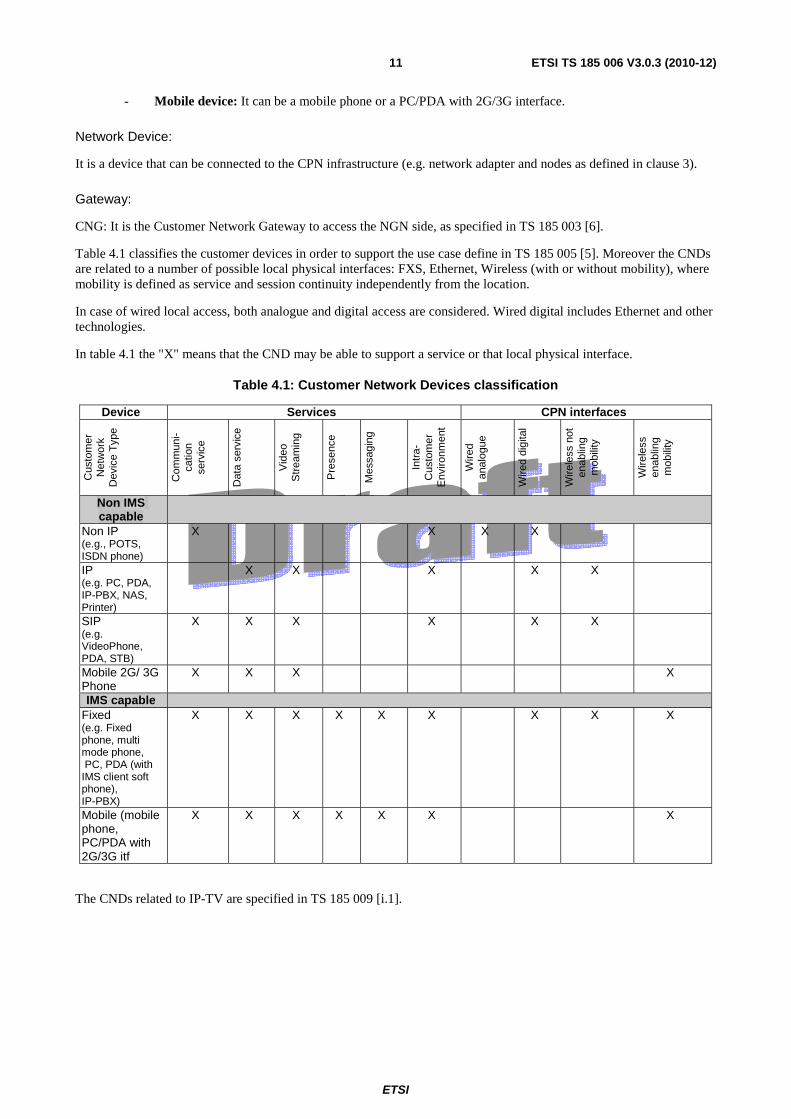
Table 4.1 classifies the customer devices in order to support the use case define in TS 185 005 [5]. Moreover the CNDs are related to a number of possible local physical interfaces: FXS, Ethernet, Wireless (with or without mobility), where mobility is defined as service and session continuity independently from the location.
In case of wired local access, both analogue and digital access are considered. Wired digital includes Ethernet and other technologies.
In table 4.1 the "X" means that the CND may be able to support a service or that local physical interface.
Table 4.1: Customer Network Devices classification
Device Services CPN interfaces
Cus
tom
er
Net
wor
k D
evic
e T
ype
Com
mun
i-ca
tion
serv
ice
Dat
a se
rvic
e
Vid
eo
Str
eam
ing
Pre
senc
e
Mes
sagi
ng
Intr
a-C
usto
mer
E
nviro
nmen
t
Wire
d an
alog
ue
Wire
d di
gita
l
Wire
less
not
en
ablin
g m
obili
ty
Wire
less
en
ablin
g m
obili
ty
Non IMS capable
Non IP (e.g., POTS, ISDN phone)
X X X X
IP (e.g. PC, PDA, IP-PBX, NAS, Printer)
X X X X X
SIP (e.g. VideoPhone, PDA, STB)
X X X X X X
Mobile 2G/ 3G Phone
X X X X
IMS capable Fixed (e.g. Fixed phone, multi mode phone, PC, PDA (with IMS client soft phone), IP-PBX)
X X X X X X X X X
Mobile (mobile phone, PC/PDA with 2G/3G itf
X X X X X X X
The CNDs related to IP-TV are specified in TS 185 009 [i.1].

ETSI
ETSI TS 185 006 V3.0.3 (2010-12)12
4.1 Non IMS capable CNDs
4.1.2 Non-IP CNDs
The non-IP devices include the POTS phone and ISDN devices; these type of devices can be connected to the NGN through the CNG or directly. In any case, the architecture of these devices is out of scope of the present document. The voice services on POTS/ISDN devices can be done in emulation [1], [2] and [3] or simulation mode on NGN. In next clause the impact on customer premises network is analyzed for both modes.
4.1.2.1 Non-IP CNDs connected to the NGN without a CNG
In this case the POTS and ISDN device is connected to the MG (Media Gateway) [3] via the Z interface for voice services, as shown in figure 4.1. In case of data services, for ISDN device, the S/T interface is needed.
The case of voice services for POTS/ISDN in PES scenario is shown in figure 4.1.
Figure 4.1: Non-IP CNDs connected to the NGN network without a CNG (PES scenario)
The case of voice services for POTS/ISDN supported in the Core IMS scenario is shown in figure 4.2.
Figure 4.2: Non-IP CNDs connected to the NGN network without a CNG (Core IMS scenario)
4.1.2.2 Non-IP CNDs connected to the NGN through a CNG
In this case, the CNG includes all the CPN functionalities necessary to fulfil a service between the analogue or ISDN phone and the NGN network. The voice services can be based on PES or Core IMS scenario. The details of CNG architecture are specified in TS 185 003 [6].
IMS Core
Customer Premises Network
POTS
ISDN
VGW
VGW S/T
Z
Gm
Gm
TISPAN PSTN/ISDN Emulation Subsystem
Customer Premises Network
POTS
ISDN AGF S/T
Z
AGW
MGW

ETSI
ETSI TS 185 006 V3.0.3 (2010-12)13
IMS Core
Customer PremisesNetwork
POTS
Z
Gm
CNGFXS
FXS
IMS CoreIMS Core
Customer PremisesNetwork
POTS
Z
Gm
CNGFXS
FXS
Figure 4.3: Non-IP CNDs connected to the NGN network trough a CNG (Core IMS scenario)
TISPAN PSTN/ISDNEmulation Subsystem
Customer PremisesNetwork
POTS
Z
a
CNGFXS
FXS
TISPAN PSTN/ISDNEmulation Subsystem
Customer PremisesNetwork
POTS
Z
a
CNGFXS
FXS
Figure 4.4: Non-IP devices connected to the NGN network trough a CNG (PES scenario)
In order to support the Z interfaces on FXS ports the CNG shall support protocol conversion as defined in TS 185 003 [6].
4.1.3 IP CNDs
These devices are able to get IP connectivity within the CPN, but they are not implementing the RFC 3261 [10] functionalities to manage signalling. This can be a communication device non compliant with RFC 3261 [10], but also devices not specifically devoted to communication services (for example: webcam with HTTP server, general purpose PC, etc.).
4.1.4 SIP IETF capable CNDs
4.1.4.1 Non-IMS SIP CND connected to the NGN through a CNG
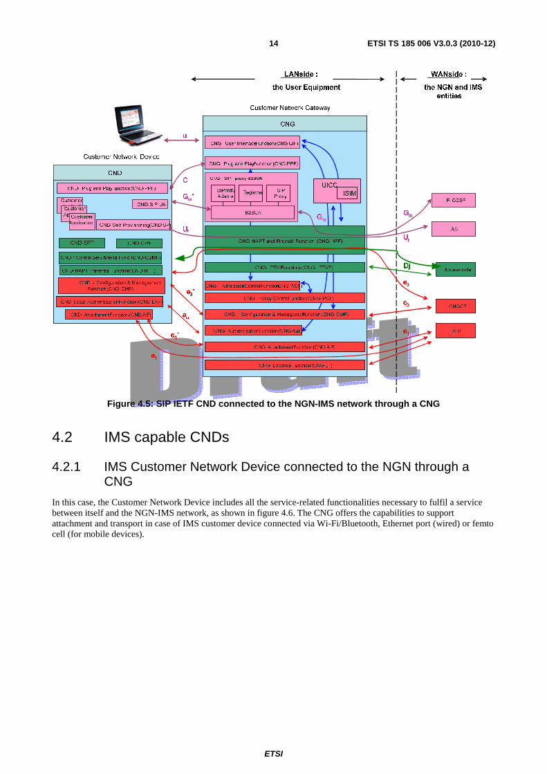
A non-IMS SIP IETF device shall utilize the Gm' reference point (instead of the Gm reference point that is utilized by
IMS capable devices) in order to get a service from NGN-IMS. See figure 4.5.
ETSI
ETSI TS 185 006 V3.0.3 (2010-12)14
Figure 4.5: SIP IETF CND connected to the NGN-IMS network through a CNG
4.2 IMS capable CNDs
4.2.1 IMS Customer Network Device connected to the NGN through a CNG
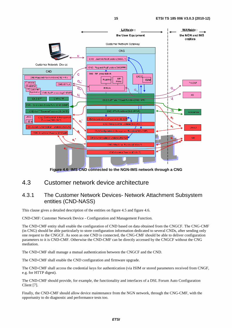
In this case, the Customer Network Device includes all the service-related functionalities necessary to fulfil a service between itself and the NGN-IMS network, as shown in figure 4.6. The CNG offers the capabilities to support attachment and transport in case of IMS customer device connected via Wi-Fi/Bluetooth, Ethernet port (wired) or femto cell (for mobile devices).
ETSI
ETSI TS 185 006 V3.0.3 (2010-12)15
Figure 4.6: IMS CND connected to the NGN-IMS network through a CNG
4.3 Customer network device architecture
4.3.1 The Customer Network Devices- Network Attachment Subsystem entities (CND-NASS)
This clause gives a detailed description of the entities on figure 4.5 and figure 4.6.
CND-CMF: Customer Network Device - Configuration and Management Function.
The CND-CMF entity shall enable the configuration of CND based on data obtained from the CNGCF. The CNG-CMF (in CNG) should be able particularly to store configuration information dedicated to several CNDs, after sending only one request to the CNGCF. As soon as one CND is connected, the CNG-CMF should be able to deliver configuration parameters to it is CND-CMF. Otherwise the CND-CMF can be directly accessed by the CNGCF without the CNG mediation.
The CND-CMF shall manage a mutual authentication between the CNGCF and the CND.
The CND-CMF shall enable the CND configuration and firmware upgrade.
The CND-CMF shall access the credential keys for authentication (via ISIM or stored parameters received from CNGF, e.g. for HTTP digest).
The CND-CMF should provide, for example, the functionality and interfaces of a DSL Forum Auto Configuration Client [7].
Finally, the CND-CMF should allow device maintenance from the NGN network, through the CNG-CMF, with the opportunity to do diagnostic and performance tests too.
CNG
LAN side :
the User Equipment
WAN side :
the NGN and IMS
entities
P- CCSF
CNGCF
ARF
Gm
e3
e1
Customer Network Gateway
CNG- User Interface Function(CNG-UIF)
e3'
e1'
Access nodeDj
CND- SIP UA
u
CNG- Location Function(CNG-LF)
AS
Ut
Ut
au
CNG- AttachmentFunction(CNG-AtF)
CND
CNG- Plug and Play Function(CNG-PPF)
CND- Plug and Play Function(CND-PPF)
C
CND- Self Provisioning(CND-SP)
Customer
ApplicationCustomer
ApplicationCustomer
Application
Gm
'
CNG-Authentication Function(CNG-AuF)
CNG- Policy Control Function(CNG- PCF)
CNG-Configuration & Management Function(CNG- CMF)
CNG-AdmissionControlFunction(CNG- ACF)
Gm
CNG- NAPT and Firewall Function(CNG- NFF)
e3
B2BUA
CNG- SIP proxy B2BUA
SIP
ProxyRegistrar
Customer Network Device
e1
ISIM
UICC
CNG- IPTV Functions(CNG- IPTVF)
Gm
CND - Comm Serv Media Func (CND-CSMF)
CND-Local Authentication Function(CND-LAF)
CND-
Function(CND- CMF)
CND- AttachmentFunction(CND-AtF)
UICC
ISIM
CND SPF CND CPF
CND- NAPT TraversalFunction(CND-NTF)
Configuration & Management
ETSI
ETSI TS 185 006 V3.0.3 (2010-12)16
Some authentication parameters may be stored in a UICC (containing the ISIM).
CND-AtF: Customer Network Device Attachment Function.
The CND-AtF entity shall store the private or public IP addresses sent by CNG-AtF or NASS (e.g. a DHCP client).
CND-LAF: Customer Network Device - Local Authentication Function.
The CND-LAF shall manage local authentication procedure to the CPN environment. For instance, a CND requesting for a CPN Wireless attachment should be authorized by the access point embedded in the CNG.
In order to ask for local authentication the CND-LAF interacts with the CNG-AuF.
The CNG-AuF can thus be configured by the user for such a case, by using the CNG User Interface Function (CNG-UIF).
4.3.2 The transfer level functions
CND-NTF: NAPT Traversal Function
The function shall allow the CNG-NFF (in CNG) traversal (as detailed in TR 187 008 [i.3]) and particularly maintain the binding between the SIP UA and the P-CSCF/C-BGF. The CND-NTF should also supply the SIP UA with the mapping made by the CNG on the NGN side so as to fill the SDP field of SIP messages sent by the CND.
4.3.3 The transport level functions
CND-CSMF: Customer Network Device-Communication Services Media Function
The CND-CSMF shall terminate the media flows.
In some cases the media flows may be encrypted.
4.3.4 The Customer Network Devices - Service-related Functional entities (CND-SF)
CND-SIP UA: Customer Network Device SIP UA
This block shall implement the Gm reference points on IMS customer devices. This SIP UA shall perform the service
authentication and manage signalling flows securely.
CND-A: Customer Network Device Client Application
At least one CND-A shall be installed on CND to support a service. There can be on or more CND-As depending on the applications installed over CND. It is a client specific for application. This client can implement local application or network services through the use of SIP UA.
CND-SC: Customer Network Device Self Configuration
This functionality is optional. It implements the Ut reference point; the Ut enables the access to an Application Sever to
support the user in configuration updates related to services.
CND-PPF: Customer Network Device - Plug and Play Function
The CNG-PPF in the CNG may obtain some device information (service discovery, description) and allow their control from the CND-PPF. Particularly, the CNG-PPF entity may allow a communication between many types of Customer Device within the CPN, not only conversational (based UPnP for instance).
CND-SPF: Customer Network Device - Service Protection Function
This function is optional. It contains the service protection software that interacts with the NGN's service protection systems. The CND contains means to upgrade the service protection software. It is used to obtain access to protected services and optionally to protect the service data integrity and the service confidentiality. The stage 2 architecture of
ETSI
ETSI TS 185 006 V3.0.3 (2010-12)17
CND-SPF is specified in TS 187 021 [19], the security requirements for the service protection function are specified in TS 187 001[18].
CND-CPF: Customer Network Device - Content Protection Function
This function is optional. It contains the content protection software that interacts with the NGN's content protection systems. The CND contains means to upgrade the content protection software. It is used for obtaining access to protected content in accordance with usage rights associated with the content. The stage 2 architecture of CND-CPF is specified in TS 187 021 [19], the security requirements for the content protection function are specified in TS 187 001[18].
5 Reference Points
5.1 Network attachment reference points e1': The e1' reference point is defined between the CND and the CNG-AtF. The CNG-AtF provides IP addresses
(IPv4 or IPv6 format) to the CND through the CND-AtF, it may also send some configuration information for the CND (typically through DHCP options).
The CND and CNG shall mutually exchange their hardware identities (e.g. MAC address, DeviceID, etc.) on e1' reference point. The CNG has to know which CNDs are behind itself within CPN and each CND has to
know its CNG.
This reference point is mandatory if the CNG runs in a routed mode.
e3': The e3' reference point is defined between the CND and the CNG-CMF. The CNG-CMF may provide the
CND with parameters that are pre-configured in the CNGCF and sent to the CNG through the e3 reference
point or, as an alternative, directly defined by the user. The CNG-CMF also configures the CNG, using information received from the CNGCF or supplied by the user himself.
The CNG-CMF also configures the CNG, it can also be provided by the CNGCF or the user himself.
Finally the CND-CMF should provide information on device status to allow the CNGCF to make some diagnostic and performance tests through the CNG-CMF.
To sum up, the e3' reference point support a variety of functionality to manage a collection of user equipment
(CNG/CNDs), including the following capabilities:
- auto-configuration and service provisioning;
- software/firmware management;
- status and performance monitoring;
- diagnostics.
This reference point is recommended as the e3 reference point could also be used. This reference point is
recommended as integration of the mandatory e3 interface described below.
In order to simplify the management functions on the CNG, the e3 reference point can be implemented directly
between CND and CNGCF as specified in ES 282 004 [12]. In this case, the direct reference point between CND and CNG, e3', could be limited to service provisioning functions; this may be required in addition or as
an alternative to the corresponding functionalities on the e3 reference point between CND and CNGCF.
au: The au reference point is defined between the Customer Network Device and the CNG-AuF. There may be two
types of authentication/authorization, according to:
ETSI
ETSI TS 185 006 V3.0.3 (2010-12)18
CPN pairing (attachment, encryption and security processes (WEP, WPA2 …)) based on specific CPN technologies (e.g. Wife SSID, PLC technology).
Access rights for some LAN services like the CNG Configuration (through the CNG-UIF).
This reference point is recommended, except if a wireless access point is embedded in the CNG in which case it is mandatory.
e1: This reference point is based on TS 183 019 [13].
The e1 reference point is dedicated to the network attachment of the User Equipment.
The e1 reference point is mandatory (in coherence with WG2 specifications).
e3: This reference point is based on ES 282 004 [12]:
The e3 reference point is defined between the CNG-CMF and the CNGCF and should be extended also
between the CNG-CMF and the CND for configuration purposes.
Through a remote management protocol it is possible to support a variety of functionalities to manage a collection of user equipment (CNG/Customer Network Devices), including the following capabilities:
- auto-configuration and service provisioning;
- software/firmware management;
- status and performance monitoring;
- diagnostics.
The e3 implementation between the CNG-CMF and the CNGCF is mandatory (in coherence with WG2
specifications), whereas the e3 implementation between the CNG-CMF and the CND-CMF is recommended,
as e3' should be an alternative.
5.2 Transport level reference points Dj: The Dj reference point is responsible for the exchange of media flows between the User Equipment (CNG or
CND) and the C-BGF.
This reference point is mandatory. It is based on ES 282 001 [14].
5.3 Service layer reference points Gm: The Gm reference point supports the communication between UE and the IMS, e.g. related to registration and
session control.
Gm between the P-CSCF and the SIP proxy B2BUA is used to support several actions:
- send SIP messages to/from the NGN;
- call forking at the CNG level.
The protocol used for the Gm reference point is SIP.
To be noticed that the definition is extracted from ES 282 007 [11].
This reference point is in line with specifications:
- ES 283 003 [4];
- TS 182 012 [3];
ETSI
ETSI TS 185 006 V3.0.3 (2010-12)19
- TS 131 103 [15].
This reference point is mandatory (in coherence with WG2 specifications).
Gm': The Gm' reference point supports the communication between one CND and the CNG, e.g. related to
registration and session control.
The difference between Gm and Gm' is related to the conformance to the IMS and to the need to go through the
B2BUA to support local services. Further details about Gm' possible implementations can be found in
TR 185 007 [i.4].
This reference point is recommended (it shall be used in case a SIP B2BUA is implemented inside the CNG).
Ut: The Ut reference point enables the user to manage information related to his services, such a creation and assignment of Public Service Identities, management of authorization policies that are used e.g. by Presence service, conference policy management, etc.
This reference point is in line with ES 282 007 [11].
This reference point is optional (in coherence with WG2 specifications, see [11]).
u: The u reference point gives the possibility to one or several users authorized (via the CNG-AuF) to have access to the CNG Configuration, through the CNG-UIF. The liaison should be as secure as possible (using HTTPs for instance).
This reference point is recommended.
C: The C reference point is defined between the CNG-PPF and the CND-PPF.
It provides some CND information (service discovery, description) to the CNG and allows its control.
Also, a communication between many types of Customer Network Device within the CPN may be established through the C reference point, using UPnP for instance.
This reference point is optional.
6 Authentication issues This clause is related to the authentication method used by customer network devices for registration and authentication on IMS core. The target authentication method is IMS AKA authentication based on ISIM/UICC, but in coherence with TS 187 001 [i.2] there are other two methods to be considered: HTTP Digest and NBA.
For that reason in the present document customer network devices, without UICC, that support HTTP Digest and NBA are considered as early deployments.
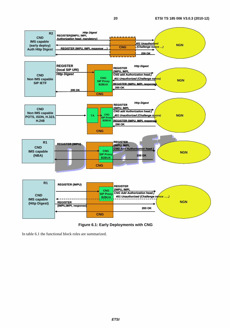
In these case of HTTP Digest or NBA a CND R2 shall be able to provide it is private and public identity in every method that requires authentication (e.g. REGISTER) in order to support shared public identity for multi device use case (shared IMPU). The CND that does not support this feature can be extended through a CNG.
In order to clarify the concept of early deployments some schemas are presented.
6.1 CNG based In case of CNG in the CPN, the CNG can be add the private identity in the Authorization Header ES 283 003 [4], if needed, both for HTTP Digest and NBA authentication method.
ETSI
ETSI TS 185 006 V3.0.3 (2010-12)20
CNG
CNDIMS capable(early deploy)
Auth Http DigestNGN
REGISTER((IMPU, IMPI,Authorization head. mandatory)
CNDNon IMS capable
SIP IETF
CNG
REGISTER(local SIP URI)
NGN
REGISTER(IMPU, IMPI,CNG add Authorization head.)
Http Digest
Http Digest
Http Digest
CNDNon IMS capable
POTS, ISDN, H.323,H.248
CNG
NGN
401 Unauthorized (Challenge nonce)
R2
CNGSIP Proxy
B2BUA
401 Unauthorized(Challenge nonce …)
CNGSIP Proxy
B2BUA
TA
REGISTER (IMPU, IMPI, response)200 OK
200 OK
REGISTER(IMPU, IMPI,CNG add Authorization head.)
Http Digest
401 Unauthorized (Challenge nonce)
REGISTER (IMPU, IMPI, response)200 OK
REGISTER (IMPU, IMPI, response …)
200 OK
CNG
CNDIMS capable(early deploy)
Auth Http DigestNGN
REGISTER((IMPU, IMPI,Authorization head. mandatory)
CNDNon IMS capable
SIP IETF
CNG
REGISTER(local SIP URI)
NGN
REGISTER(IMPU, IMPI,CNG add Authorization head.)
Http Digest
Http Digest
Http Digest
CNDNon IMS capable
POTS, ISDN, H.323,H.248
CNG
NGN
401 Unauthorized (Challenge nonce)
R2
CNGSIP Proxy
B2BUA
401 Unauthorized(Challenge nonce …)
CNGSIP Proxy
B2BUA
TA
REGISTER (IMPU, IMPI, response)200 OK
200 OK
REGISTER(IMPU, IMPI,CNG add Authorization head.)
Http Digest
401 Unauthorized (Challenge nonce)
REGISTER (IMPU, IMPI, response)200 OK
REGISTER (IMPU, IMPI, response …)
200 OK
CNDIMS capable
(NBA)NGN
REGISTER (IMPU)R1
CNG
REGISTER(IMPU, IMPI,CNG Add Authorization head.)
CNGSIP Proxy
B2BUA
CNDIMS capable(Http Digest) NGN
REGISTER (IMPU)R1
CNG
REGISTER(IMPU, IMPI,CNG Add Authorization head.)
CNGSIP Proxy
B2BUA 401 Unauthorized (Challenge nonce …..)
200 OK
REGISTER (IMPU,IMPI, response)
200 OK
Figure 6.1: Early Deployments with CNG
In table 6.1 the functional block roles are summarized.
ETSI
ETSI TS 185 006 V3.0.3 (2010-12)21
Table 6.1: Functional block rules for authentication (CNG based)
CND CND => NGN CNG NGN IMS Capable Early deployment R2 (HTTP Digest)
CND sends REGISTER with authorization header including IMPI.
Transparent. NGN sends 401 unauthorized and challenge the CND.
Non IMS Capable SIP IETF (HTTP Digest)
CND sends REGISTER without authorization header.
The SIP UA (IETF) receives the REGISTER The B2BUA close the session with SIP IETF and open a new session with NGN adding the authorization head with CND's IMPI.
NGN sends 401 unauthorized and challenge the CND trough the B2BUA inside the CNG.
Non IMS Capable (POTS, ISDN, H323, H248)
CND generates local signalling to the Terminal Adapter (TA).
The B2BUA opens a new session with NGN adding the authorization head with CNG's IMPI.
NGN sends 401 unauthorized and challenge the CND trough the B2BUA inside the CNG.
IMS Capable R1 (NBA)
CND sends REGISTER without authorization header.
The B2BUA can modify the REGISTER to the NGN adding the authorization head with CND's IMPI.
The NGN does not challenge the CND because NBA is used.
IMS Capable R1 (HTTP Digest)
CND sends REGISTER without authorization header.
The B2BUA can modify the REGISTER to the NGN adding the authorization head with CND's IMPI.
NGN sends 401 unauthorized and challenge the CND.
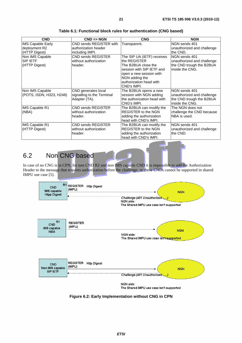
6.2 Non CNG based In case of no CNG is in CPN, for non CND R2 and non IMS capable CND it is impossible to add the Authorization Header to the message that requires authorization before the challenge, so these CNDs cannot be supported in shared IMPU use case [5].
Figure 6.2: Early Implementation without CNG in CPN
ETSI
ETSI TS 185 006 V3.0.3 (2010-12)22
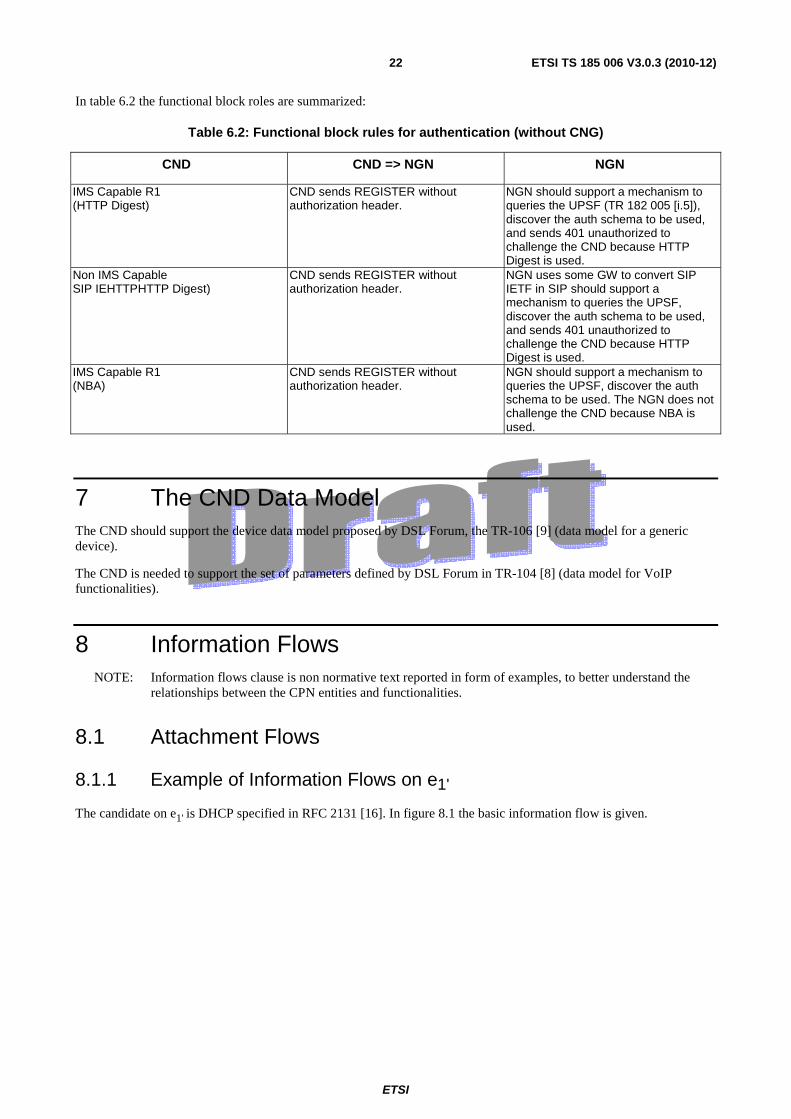
In table 6.2 the functional block roles are summarized:
Table 6.2: Functional block rules for authentication (without CNG)
CND CND => NGN NGN
IMS Capable R1 (HTTP Digest)
CND sends REGISTER without authorization header.
NGN should support a mechanism to queries the UPSF (TR 182 005 [i.5]), discover the auth schema to be used, and sends 401 unauthorized to challenge the CND because HTTP Digest is used.
Non IMS Capable SIP IEHTTPHTTP Digest)
CND sends REGISTER without authorization header.
NGN uses some GW to convert SIP IETF in SIP should support a mechanism to queries the UPSF, discover the auth schema to be used, and sends 401 unauthorized to challenge the CND because HTTP Digest is used.
IMS Capable R1 (NBA)
CND sends REGISTER without authorization header.
NGN should support a mechanism to queries the UPSF, discover the auth schema to be used. The NGN does not challenge the CND because NBA is used.
7 The CND Data Model The CND should support the device data model proposed by DSL Forum, the TR-106 [9] (data model for a generic device).
The CND is needed to support the set of parameters defined by DSL Forum in TR-104 [8] (data model for VoIP functionalities).
8 Information Flows NOTE: Information flows clause is non normative text reported in form of examples, to better understand the
relationships between the CPN entities and functionalities.
8.1 Attachment Flows
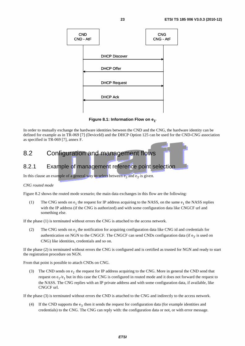
8.1.1 Example of Information Flows on e1'
The candidate on e1' is DHCP specified in RFC 2131 [16]. In figure 8.1 the basic information flow is given.
ETSI
ETSI TS 185 006 V3.0.3 (2010-12)23
CNDCND - AtF
CNGCNG - AtF
DHCP Discover
DHCP Offer
DHCP Request
DHCP Ack
CNDCND - AtF
CNGCNG - AtF
DHCP Discover
DHCP Offer
DHCP Request
DHCP Ack
Figure 8.1: Information Flow on e1'
In order to mutually exchange the hardware identities between the CND and the CNG, the hardware identity can be defined for example as in TR-069 [7] (DeviceId) and the DHCP Option 125 can be used for the CND-CNG association as specified in TR-069 [7], annex F.
8.2 Configuration and management flows
8.2.1 Example of management reference point selection
In this clause an example of a general way to select between e3 and e3' is given.
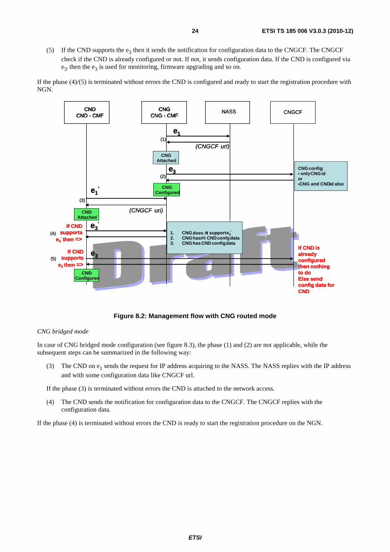
CNG routed mode
Figure 8.2 shows the routed mode scenario; the main data exchanges in this flow are the following:
(1) The CNG sends on e1 the request for IP address acquiring to the NASS, on the same e1 the NASS replies
with the IP address (if the CNG is authorized) and with some configuration data like CNGCF url and something else.
If the phase (1) is terminated without errors the CNG is attached to the access network.
(2) The CNG sends on e3 the notification for acquiring configuration data like CNG id and credentials for
authentication on NGN to the CNGCF. The CNGCF can send CNDs configuration data (if e3' is used on
CNG) like identities, credentials and so on.
If the phase (2) is terminated without errors the CNG is configured and is certified as trusted for NGN and ready to start the registration procedure on NGN.
From that point is possible to attach CNDs on CNG.
(3) The CND sends on e1' the request for IP address acquiring to the CNG. More in general the CND send that
request on e1'/e1 but in this case the CNG is configured in routed mode and it does not forward the request to
the NASS. The CNG replies with an IP private address and with some configuration data, if available, like CNGCF url.
If the phase (3) is terminated without errors the CND is attached to the CNG and indirectly to the access network.
(4) If the CND supports the e3' then it sends the request for configuration data (for example identities and
credentials) to the CNG. The CNG can reply with: the configuration data or not, or with error message.
ETSI
ETSI TS 185 006 V3.0.3 (2010-12)24
(5) If the CND supports the e3 then it sends the notification for configuration data to the CNGCF. The CNGCF
check if the CND is already configured or not. If not, it sends configuration data. If the CND is configured via e3' then the e3 is used for monitoring, firmware upgrading and so on.
If the phase (4)/(5) is terminated without errors the CND is configured and ready to start the registration procedure with NGN.
Figure 8.2: Management flow with CNG routed mode
CNG bridged mode
In case of CNG bridged mode configuration (see figure 8.3), the phase (1) and (2) are not applicable, while the subsequent steps can be summarized in the following way:
(3) The CND on e1 sends the request for IP address acquiring to the NASS. The NASS replies with the IP address
and with some configuration data like CNGCF url.
If the phase (3) is terminated without errors the CND is attached to the network access.
(4) The CND sends the notification for configuration data to the CNGCF. The CNGCF replies with the configuration data.
If the phase (4) is terminated without errors the CND is ready to start the registration procedure on the NGN.
CND CND - CMF
CNGCNG - CMF
CND CND - CMF
CNGCNG - CMF
CNGCF NASS
e1
(CNGCF url )CNG
Attached
e3 CNG config: • onlyCNG idor•CNG and CND id also
e1’
(CNGCF url)
e3’If CND
supportse3
’ then =>1. CNG doesn’ t support e 3’
2. CNG hasn’t CND confgdata3. CNG has CND configdata
If CND supports
e3 then =>
e3
If CND isalreadyconfigured then nothing to do Else sendconfig data forCND
CND Attached
(4)
(2)
(3)
(1)
(5)
CNGConfigured
CND Configured
CND CND - CMF
CNGCNG - CMF
CND CND - CMF
CNGCNG - CMF
CNGCF NASS
e1
(CNGCF url )CNG
Attached
e3 CNG config: • onlyCNG idor•CNG and CND id also
e1’
(CNGCF url)
e3’If CND
supportse3
’ then =>1. CNG does n’ t support e 3’
2. CNG hasn’t CND confgdata3. CNG has CND configdata
If CND supports
e3 then =>
e3
If CND isalreadyconfigured then nothing to do Else sendconfig data forCND
CND Attached
(4)
(2)
(3)
(1)
(5)
CNGConfigured
CND Configured
ETSI
ETSI TS 185 006 V3.0.3 (2010-12)25
CNDCND - CMF
CNGCNG - CMF
CNDCND - CMF
CNGCNG - CMF
CNGCFNASS
e1
(CNGCF url)
CNGAttached
e3 CNG config:• only CNG id
e1
(CNGCF url)
CND config data
e3
CNDAttached
(2)
(3)
(1)
(4)
CNDConfigured
CNGConfigured
CNDCND - CMF
CNGCNG - CMF
CNDCND - CMF
CNGCNG - CMF
CNGCFNASS
e1
(CNGCF url)
CNGAttached
e3 CNG config:• only CNG id
e1
(CNGCF url)
CND config data
e3
CNDAttached
(2)
(3)
(1)
(4)
CNDConfigured
CNGConfigured
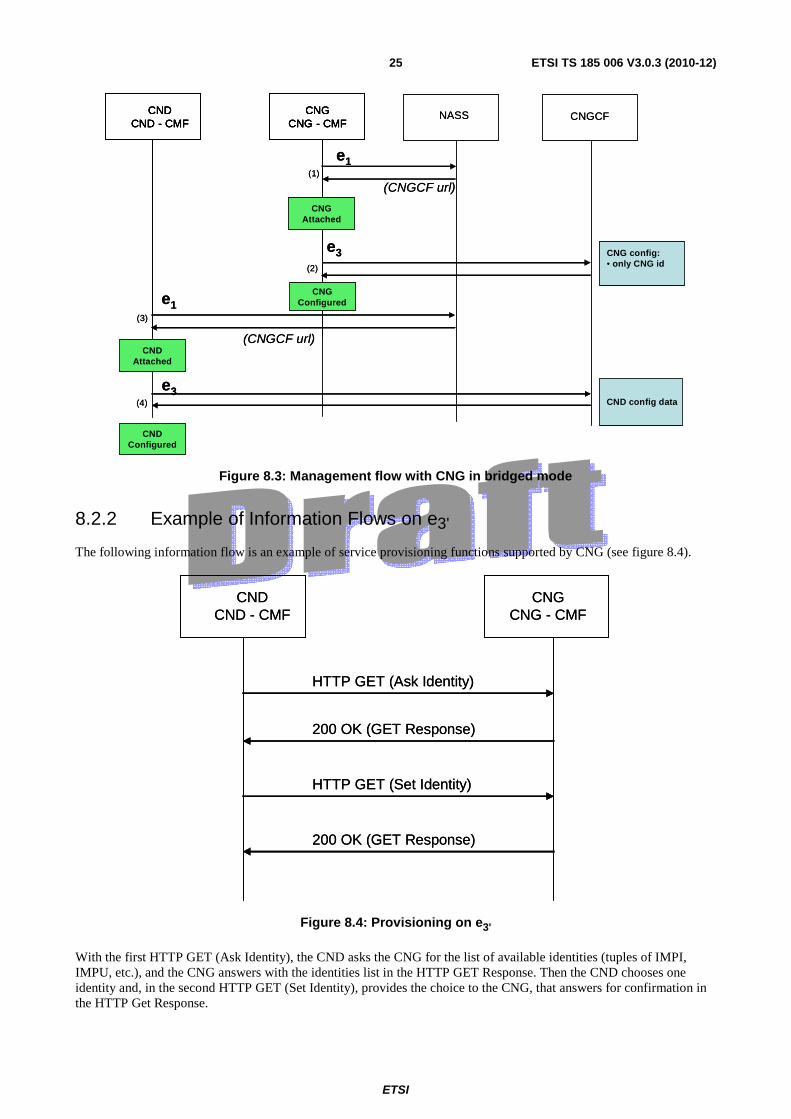
Figure 8.3: Management flow with CNG in bridged mode
8.2.2 Example of Information Flows on e3'
The following information flow is an example of service provisioning functions supported by CNG (see figure 8.4).
CNDCND - CMF
CNGCNG - CMF
HTTP GET (Ask Identity)
200 OK (GET Response)
HTTP GET (Set Identity)
200 OK (GET Response)
CNDCND - CMF
CNGCNG - CMF
HTTP GET (Ask Identity)
200 OK (GET Response)
HTTP GET (Set Identity)
200 OK (GET Response)
Figure 8.4: Provisioning on e3'
With the first HTTP GET (Ask Identity), the CND asks the CNG for the list of available identities (tuples of IMPI, IMPU, etc.), and the CNG answers with the identities list in the HTTP GET Response. Then the CND chooses one identity and, in the second HTTP GET (Set Identity), provides the choice to the CNG, that answers for confirmation in the HTTP Get Response.

ETSI
ETSI TS 185 006 V3.0.3 (2010-12)26
8.3 Signalling flows The candidate on Gm' is SIP specified in RFC 3261 [10], the one on Gm is SIP specified in TS 124 229 [17] and
ES 283 003 [4].
8.3.1 CND attachment and NGN registration
The non-IMS devices considered in this case are devices associated to the VoIP phone number of the CNG.
Different kinds of devices (see table 4.1):
• Fixed or Wireless SIP phone.
• SIP Multi-mode (e.g. dual WI-Fi/3G phone).
• SIP soft phone on PC.
• Other: play station, STB, etc.
These SIP devices have a local SIP identity, as defined as local SIP URI (e.g. device kitchen) or public SIP URI (e.g. John123):
• The vendor provides a local SIP identity for all SIP devices. This enables "Plug and play" functionality. User does not need to configure the SIP device. By default, this local identity can be the MAC address.
• The user can change the local identity provided by the vendor to another local identity. The user may also be allowed to change the local identity to a public SIP URI. The customer can change this parameterization, and select a specific name or a local phone number for each device.
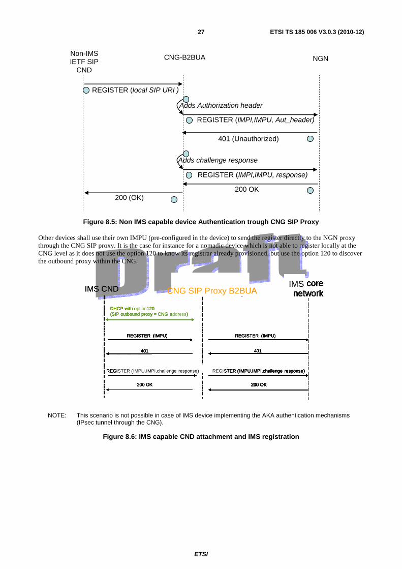
The attachment phase is defined in the following way (see figure 8.5):
1) In case Gm' needs to be used (for local services), the DHCP server of the CNG will return the DHCP option
120 to the CND, standardized to provision CNG SIP proxy IP address or domain-name. This option will contain the IP address of the CNG on the CPN side (ex: 192.168.1.1).
2) The device registers locally to the CNG SIP-IMS proxy. SIP REGISTER message is sent with the local SIP URI of the device.
3) So as to allow the device to communicate through the NGN, the customer can configure the association between the local SIP URI of the device (pre-configured in the device) and the CNG's IMPU, or the device can use its own IMPU (public SIP URI pre-configured in the device) to send the register through the CNG SIP proxy. In those cases only one register has to be sent from the CNG to the NGN for multiple CND IMPUs within the CPN.
The authentication is handled directly by the CNG-SIP proxy B2BUA.
ETSI
ETSI TS 185 006 V3.0.3 (2010-12)27
Non-IMS IETF SIP
CND
CNG-B2BUA NGN
REGISTER (local SIP URI )
200 (OK)
REGISTER (IMPI,IMPU, Aut_header)
200 OK
Adds challenge response
401 (Unauthorized)
REGISTER (IMPI,IMPU, response)
Adds Authorization header
1
2
3
4
5
7
8
6
Figure 8.5: Non IMS capable device Authentication trough CNG SIP Proxy
Other devices shall use their own IMPU (pre-configured in the device) to send the register directly to the NGN proxy through the CNG SIP proxy. It is the case for instance for a nomadic device which is not able to register locally at the CNG level as it does not use the option 120 to know its registrar already provisioned, but use the option 120 to discover the outbound proxy within the CNG.
with
CNGCNG SIP proxyIMS
with
CNG
REGISTER (IMPU)
200 OK
401
(SIP outbound proxy = CNG address)
)
SIP- IMS ProxySIP corenetwork
IMS
200 OK
REGISTER (IMPU,IMPI,challenge response)
SIP- IMS ProxySIP corenetwork
IMS
DHCP with option120
CNGCNG SIP proxy
401
200 OK
REGISTER (IMPU)
REGISTER (IMPU,IMPI,challenge response)
with
CNGCNG SIP proxyIMS
with
CNG
REGISTER (IMPU)
200 OK
401
(SIP outbound proxy = CNG address)
)
SIP- IMS ProxySIP corenetwork
IMS
200 OK
REGISTER (IMPU,IMPI,challenge response)
SIP- IMS ProxySIP corenetwork
IMS
DHCP with option120
CNGCNG SIP Proxy B2BUA
401
200 OK
REGISTER (IMPU)
REGISTER (IMPU,IMPI,challenge response)
IMS CND
with
CNGCNG SIP proxyIMS
with
CNG
REGISTER (IMPU)
200 OK
401
(SIP outbound proxy = CNG address)
)
SIP- IMS ProxySIP corenetwork
IMS
200 OK
REGISTER (IMPU,IMPI,challenge response)
SIP- IMS ProxySIP corenetwork
IMS
DHCP with option120
CNGCNG SIP proxy
401
200 OK
REGISTER (IMPU)
REGISTER (IMPU,IMPI,challenge response)
with
CNGCNG SIP proxyIMS
with
CNG
REGISTER (IMPU)
200 OK
401
(SIP outbound proxy = CNG address)
)
SIP- IMS ProxySIP corenetwork
IMS
200 OK
REGISTER (IMPU,IMPI,challenge response)
SIP- IMS ProxySIP corenetwork
IMS
DHCP with option120
CNGCNG SIP Proxy B2BUA
401
200 OK
REGISTER (IMPU)
REGISTER (IMPU,IMPI,challenge response)
IMS CND
NOTE: This scenario is not possible in case of IMS device implementing the AKA authentication mechanisms (IPsec tunnel through the CNG).
Figure 8.6: IMS capable CND attachment and IMS registration
ETSI
ETSI TS 185 006 V3.0.3 (2010-12)28
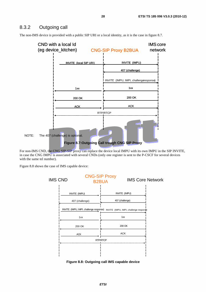
8.3.2 Outgoing call
The non-IMS device is provided with a public SIP URI or a local identity, as it is the case in figure 8.7.
INVITE (local SIP URI)
200 OK
407 (challenge)
INVITE (IMPU, IMPI, challengeresponse)
CND with a local Id(eg device_kitchen) CNG-SIP Proxy B2BUA
IMS corenetwork
1xx
ACK
INVITE (IMPU)
RTP/RTCP
1xx
200 OK
ACK
INVITE (local SIP URI)
200 OK
407 (challenge)
INVITE (IMPU, IMPI, challengeresponse)
CND with a local Id(eg device_kitchen) CNG-SIP Proxy B2BUA
IMS corenetwork
1xx
ACK
INVITE (IMPU)
RTP/RTCP
1xx
200 OK
ACK
NOTE: The 407 (challenge) is optional.
Figure 8.7:Outgoing Call trough CNG SIP Proxy
For non-IMS CND, the CNG SIP-SIP proxy can replace the device local IMPU with its own IMPU in the SIP INVITE, in case the CNG IMPU is associated with several CNDs (only one register is sent to the P-CSCF for several devices with the same tel number).
Figure 8.8 shows the case of IMS capable device:
INVITE (IMPU)
200 OK
407 (challenge)
INVITE (IMPU, IMPI, challenge response)
SIP "nomadic" terminal SIP-IMS Proxy
SIP corenetwork
1xx
ACK
INVITE (IMPU)
RTP/RTCP
IMS CNDCNG-SIP Proxy
B2BUA IMS Core Network
407 (challenge)
INVITE (IMPU, IMPI, challenge response
1xx
200 OK
ACK
Figure 8.8: Outgoing call IMS capable device

ETSI
ETSI TS 185 006 V3.0.3 (2010-12)29
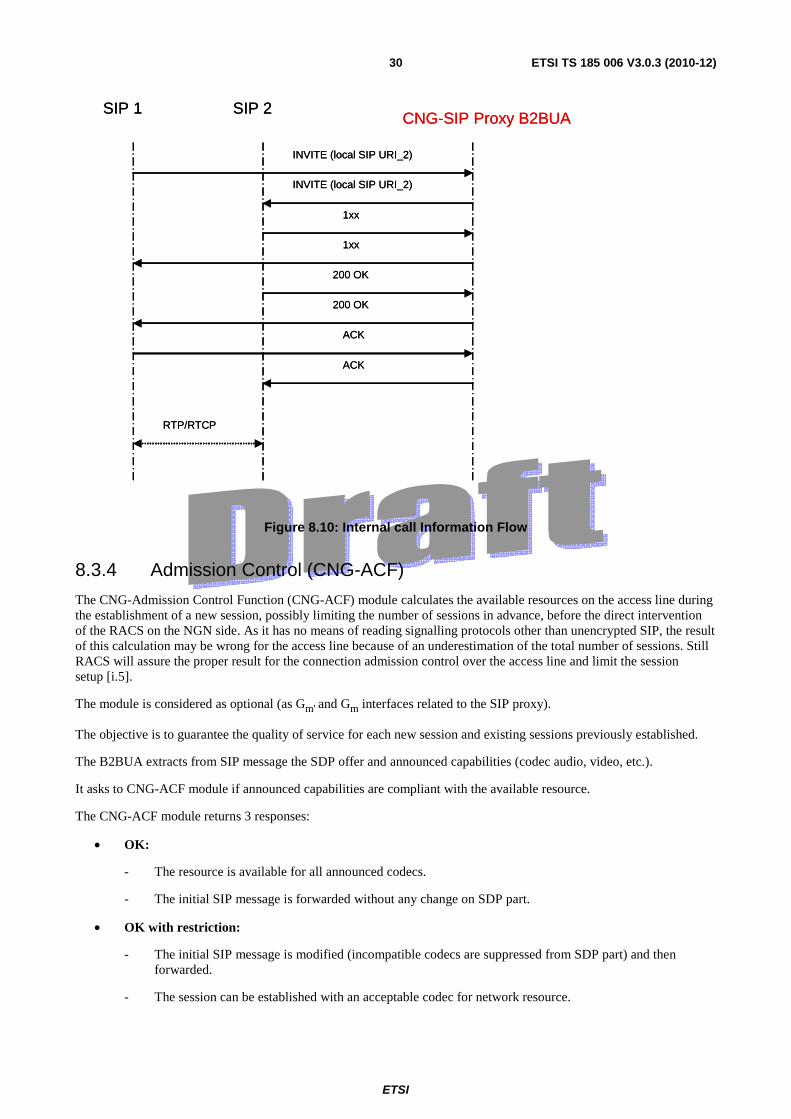
8.3.3 Internal Call
The CNG SIP- proxy can route local call between 2 devices of the CPN.
No NGN resource is used to establish internal call.
SIP signalling is not forwarded to core network and media streams are kept on the CPN directly between endpoints.
The CNG SIP proxy identifies internal call after the analysis of the called party number.
The customer can dial:
• Directly the local identity of the device (e.g.: kitchen, dect, John, etc.).
• Or a private numbering plan. The commutation table is configurable for instance by the customer by the web server of the CNG (via U reference point).
Figure 8.9: Internal Call Use Case
ETSI
ETSI TS 185 006 V3.0.3 (2010-12)30
SIP 1 SIP 2CNG-SIP Proxy B2BUA
INVITE (local SIP URI_2)
INVITE (local SIP URI_2)
1xx
1xx
200 OK
200 OK
ACK
ACK
RTP/RTCP
SIP 1 SIP 2CNG-SIP Proxy B2BUA
INVITE (local SIP URI_2)
INVITE (local SIP URI_2)
1xx
1xx
200 OK
200 OK
ACK
ACK
RTP/RTCP
Figure 8.10: Internal call Information Flow
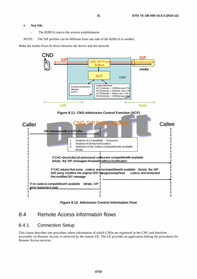
8.3.4 Admission Control (CNG-ACF)
The CNG-Admission Control Function (CNG-ACF) module calculates the available resources on the access line during the establishment of a new session, possibly limiting the number of sessions in advance, before the direct intervention of the RACS on the NGN side. As it has no means of reading signalling protocols other than unencrypted SIP, the result of this calculation may be wrong for the access line because of an underestimation of the total number of sessions. Still RACS will assure the proper result for the connection admission control over the access line and limit the session setup [i.5].
The module is considered as optional (as Gm' and Gm interfaces related to the SIP proxy).
The objective is to guarantee the quality of service for each new session and existing sessions previously established.
The B2BUA extracts from SIP message the SDP offer and announced capabilities (codec audio, video, etc.).
It asks to CNG-ACF module if announced capabilities are compliant with the available resource.
The CNG-ACF module returns 3 responses:
• OK:
- The resource is available for all announced codecs.
- The initial SIP message is forwarded without any change on SDP part.
• OK with restriction:
- The initial SIP message is modified (incompatible codecs are suppressed from SDP part) and then forwarded.
- The session can be established with an acceptable codec for network resource.
ETSI
ETSI TS 185 006 V3.0.3 (2010-12)31
• Not OK:
- The B2BUA rejects the session establishment.
NOTE: The SIP profiles can be different from one side of the B2BUA to another.
Make the media flows be direct between the device and the network.
CNG
CND
LAN WAN
SIP
Codecreference•G711: bitrate = 100Kbps ; cpu=7%•G722: bitrate = 100Kbps ; cpu=7%•G729: bitrate = 45Kps ; cpu = 5%•H263: bitrate = 156Kbps ; cpu=9%
SIP
Dynamical pointers#bitrate#CPU
ACF
media
CNG SIP ProxyB2BUA
CNGCNG
CND
LAN WAN
SIP
Codecreference•G711: bitrate = 100Kbps ; cpu=7%•G722: bitrate = 100Kbps ; cpu=7%•G729: bitrate = 45Kps ; cpu = 5%•H263: bitrate = 156Kbps ; cpu=9%
SIP
Dynamical pointers#bitrate#CPU
ACF
media
CNG SIP ProxyB2BUA
CNG
Figure 8.11: CNG-Admission Control Function (ACF)
L2
Caller CNG SIP Proxy B2BUA CalleeSIP messagewith a SDP offer
1. Analysis of L2 available resources2. Analysis of announced codecs3. Selection of the codecs compatible with available
bitrate
If CAC returns that all announced codecsare compatiblewith availablebitrate, the SIP messageis forwardedwithoutmodification
If no codecis compatiblewith available bitrate, SIP error responseis sent
If CAC returns that some codecs are incompatiblewith available bitrate, the SIP-IMS proxy modifies the original SDP bysuppressingthese codecs and forwardedthis modifiedSIP message
Figure 8.12: Admission Control Information Flow
8.4 Remote Access information flows
8.4.1 Connection Setup
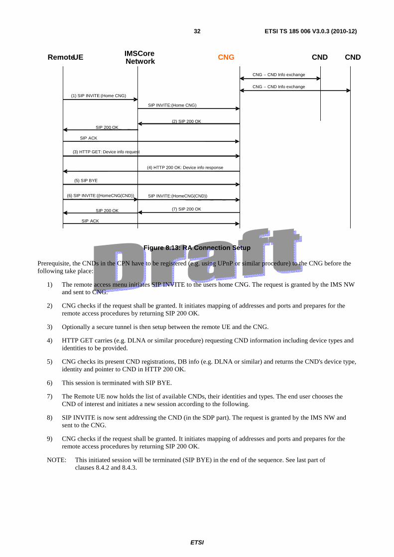
This clause describes one procedure where information of which CNDs are registered in the CNG and therefore accessible via Remote Access, is retrieved by the remote UE. The UE provides an application linking the procedures for Remote Access services.
ETSI
ETSI TS 185 006 V3.0.3 (2010-12)32
SIP ACK
SIP ACK
Remote UE IMS CoreNetwork CNG CND CND
(1) SIP INVITE:(Home CNG) SIP INVITE:(Home CNG)
CNG – CND Info exchange
CNG – CND Info exchange
(2) SIP 200 OK SIP 200 OK
(3) HTTP GET: Device info request
(4) HTTP 200 OK: Device info response
(5) SIP BYE
(6) SIP INVITE:(( HomeCNG (CND)) SIP INVITE:( HomeCNG (CND))
(7) SIP 200 OK SIP 200 OK
Figure 8.13: RA Connection Setup
Prerequisite, the CNDs in the CPN have to be registered (e.g. using UPnP or similar procedure) to the CNG before the following take place:
1) The remote access menu initiates SIP INVITE to the users home CNG. The request is granted by the IMS NW and sent to CNG.
2) CNG checks if the request shall be granted. It initiates mapping of addresses and ports and prepares for the remote access procedures by returning SIP 200 OK.
3) Optionally a secure tunnel is then setup between the remote UE and the CNG.
4) HTTP GET carries (e.g. DLNA or similar procedure) requesting CND information including device types and identities to be provided.
5) CNG checks its present CND registrations, DB info (e.g. DLNA or similar) and returns the CND's device type, identity and pointer to CND in HTTP 200 OK.
6) This session is terminated with SIP BYE.
7) The Remote UE now holds the list of available CNDs, their identities and types. The end user chooses the CND of interest and initiates a new session according to the following.
8) SIP INVITE is now sent addressing the CND (in the SDP part). The request is granted by the IMS NW and sent to the CNG.
9) CNG checks if the request shall be granted. It initiates mapping of addresses and ports and prepares for the remote access procedures by returning SIP 200 OK.
NOTE: This initiated session will be terminated (SIP BYE) in the end of the sequence. See last part of clauses 8.4.2 and 8.4.3.
ETSI
ETSI TS 185 006 V3.0.3 (2010-12)33
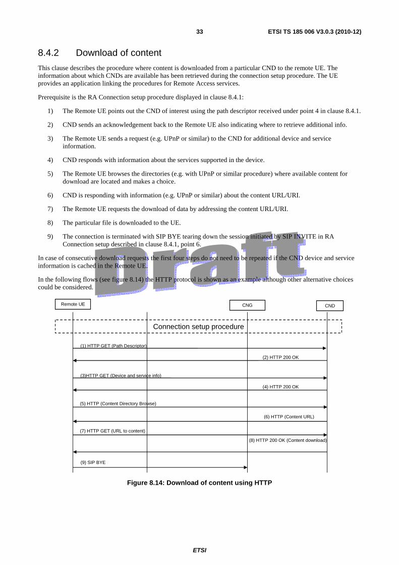
8.4.2 Download of content
This clause describes the procedure where content is downloaded from a particular CND to the remote UE. The information about which CNDs are available has been retrieved during the connection setup procedure. The UE provides an application linking the procedures for Remote Access services.
Prerequisite is the RA Connection setup procedure displayed in clause 8.4.1:
1) The Remote UE points out the CND of interest using the path descriptor received under point 4 in clause 8.4.1.
2) CND sends an acknowledgement back to the Remote UE also indicating where to retrieve additional info.
3) The Remote UE sends a request (e.g. UPnP or similar) to the CND for additional device and service information.
4) CND responds with information about the services supported in the device.
5) The Remote UE browses the directories (e.g. with UPnP or similar procedure) where available content for download are located and makes a choice.
6) CND is responding with information (e.g. UPnP or similar) about the content URL/URI.
7) The Remote UE requests the download of data by addressing the content URL/URI.
8) The particular file is downloaded to the UE.
9) The connection is terminated with SIP BYE tearing down the session initiated by SIP INVITE in RA Connection setup described in clause 8.4.1, point 6.
In case of consecutive download requests the first four steps do not need to be repeated if the CND device and service information is cached in the Remote UE.
In the following flows (see figure 8.14) the HTTP protocol is shown as an example although other alternative choices could be considered.
Remote UE CNG CND
(1) HTTP GET (Path Descriptor)
(5) HTTP (Content Directory Browse)
(7) HTTP GET (URL to content)
(9) SIP BYE
Connection setup procedure
(2) HTTP 200 OK
(3)HTTP GET (Device and service info)
(4) HTTP 200 OK
(8) HTTP 200 OK (Content download)
(6) HTTP (Content URL)
Figure 8.14: Download of content using HTTP
ETSI
ETSI TS 185 006 V3.0.3 (2010-12)34
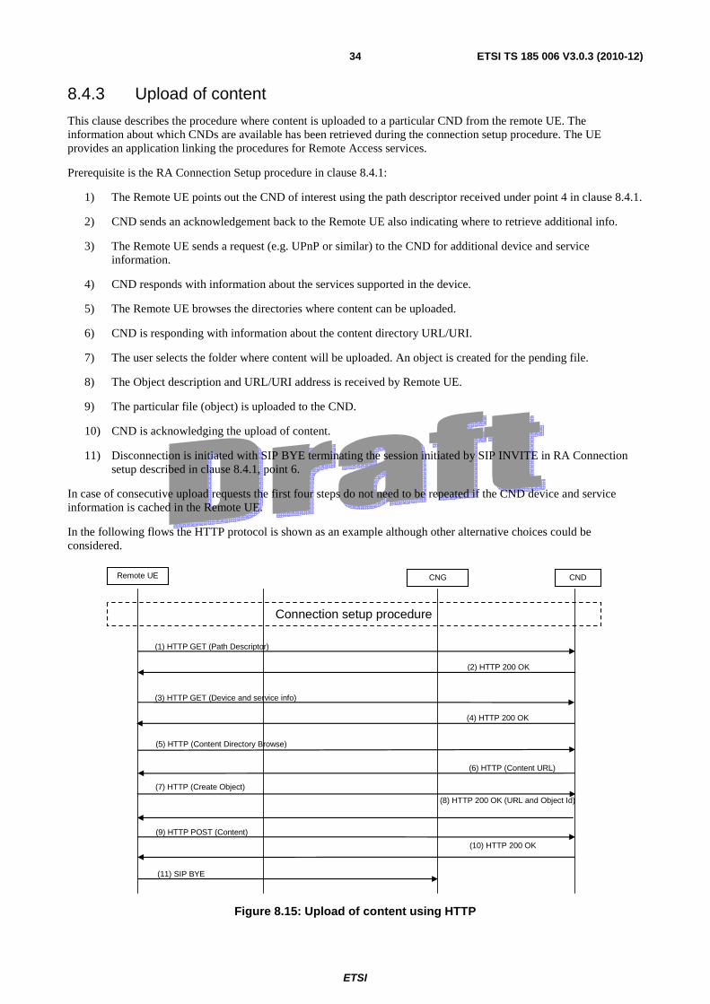
8.4.3 Upload of content
This clause describes the procedure where content is uploaded to a particular CND from the remote UE. The information about which CNDs are available has been retrieved during the connection setup procedure. The UE provides an application linking the procedures for Remote Access services.
Prerequisite is the RA Connection Setup procedure in clause 8.4.1:
1) The Remote UE points out the CND of interest using the path descriptor received under point 4 in clause 8.4.1.
2) CND sends an acknowledgement back to the Remote UE also indicating where to retrieve additional info.
3) The Remote UE sends a request (e.g. UPnP or similar) to the CND for additional device and service information.
4) CND responds with information about the services supported in the device.
5) The Remote UE browses the directories where content can be uploaded.
6) CND is responding with information about the content directory URL/URI.
7) The user selects the folder where content will be uploaded. An object is created for the pending file.
8) The Object description and URL/URI address is received by Remote UE.
9) The particular file (object) is uploaded to the CND.
10) CND is acknowledging the upload of content.
11) Disconnection is initiated with SIP BYE terminating the session initiated by SIP INVITE in RA Connection setup described in clause 8.4.1, point 6.
In case of consecutive upload requests the first four steps do not need to be repeated if the CND device and service information is cached in the Remote UE.
In the following flows the HTTP protocol is shown as an example although other alternative choices could be considered.
Remote UE CNG CND
(1) HTTP GET (Path Descriptor)
(5) HTTP (Content Directory Browse)
(9) HTTP POST (Content)
(11) SIP BYE
Connection setup procedure
(2) HTTP 200 OK
(3) HTTP GET (Device and service info)
(4) HTTP 200 OK
(10) HTTP 200 OK
(6) HTTP (Content URL)
(7) HTTP (Create Object)
(8) HTTP 200 OK (URL and Object Id)
Figure 8.15: Upload of content using HTTP

ETSI
ETSI TS 185 006 V3.0.3 (2010-12)35
Annex A (informative): Bibliography
• HGI - Home Gateway Technical Requirements.
• ETSI TS 183 023: "Telecommunications and Internet converged Services and Protocols for Advanced Networking (TISPAN); PSTN/ISDN simulation services; Extensible Markup Language (XML) Configuration Access Protocol (XCAP) over the Ut interface for Manipulating NGN PSTN/ISDN Simulation Services".
• ETSI ES 282 003: "Telecommunications and Internet converged Services and Protocols for Advanced Networking (TISPAN); Resource and Admission Control Sub-system (RACS); Functional Architecture".

ETSI
ETSI TS 185 006 V3.0.3 (2010-12)36
Annex B (informative): Change history
Date WG Doc. CR Rev CAT Title / Comment Current Version
New Version
05-02-10 TISPAN05(10)0008r2
001 D Update of scope of release 3 2.3.1 3.0.0
Update of Change history annex by secretariat 3.0.0 3.0.1 22-06-10 TISPAN05(1
0)0037r3 002 TS 185 006 CR on CND Portability 3.0.1 3.0.2
15-12-10 TISPAN05(10)0081
003 Removed "through the CND-CSMF" in 4.3.4 3.0.2 3.0.3

ETSI
ETSI TS 185 006 V3.0.3 (2010-12)37
History
Document history
V2.0.0 March 2008 Publication
V2.3.1 May 2009 Publication
V3.0.0 February, 2010 Draft for Release 3, with only update of scope.
V3.0.1 February, 2010 ETSIhelp created latest draft
V3.0.2 June, 2010 Applied TISPAN05(10)0037r3 CR002 to add feature of -CND-SPF and CND-CPF, plus update definitions and do tidy up