Embed Size (px)
Citation preview
ETSI EN 301 489-1 V2.1.1 (2017-02)
Electromagnetic compatibility and Radio spectrum Matters (ERM);
ElectroMagnetic Compatibility (EMC) standard for radio equipment and services;
Part 1: Common technical requirements ElectroMagnetic Compatibility (EMC)
standard for radio equipment and services; Part 1: Common technical requirements;
Harmonised Standard covering the essential requirements of article 6 of Directive 2014/30/EU
HARMONISED EUROPEAN STANDARD
ETSI
ETSI EN 301 489-1 V2.1.1 (2017-02) 2
Reference
REN/ERM-EMC-268-1333
Keywords
EMC, harmonised standard, radio, regulation
ETSI
650 Route des Lucioles F-06921 Sophia Antipolis Cedex - FRANCE
Tel.: +33 4 92 94 42 00 Fax: +33 4 93 65 47 16
Siret N° 348 623 562 00017 - NAF 742 C
Association à but non lucratif enregistrée à la Sous-Préfecture de Grasse (06) N° 7803/88
Important notice
The present document can be downloaded from: http://www.etsi.org/standards-search
The present document may be made available in electronic versions and/or in print. The content of any electronic and/or print versions of the present document shall not be modified without the prior written authorization of ETSI. In case of any
existing or perceived difference in contents between such versions and/or in print, the only prevailing document is the print of the Portable Document Format (PDF) version kept on a specific network drive within ETSI Secretariat.
Users of the present document should be aware that the document may be subject to revision or change of status. Information on the current status of this and other ETSI documents is available at
https://portal.etsi.org/TB/ETSIDeliverableStatus.aspx
If you find errors in the present document, please send your comment to one of the following services: https://portal.etsi.org/People/CommiteeSupportStaff.aspx
Copyright Notification
No part may be reproduced or utilized in any form or by any means, electronic or mechanical, including photocopying and microfilm except as authorized by written permission of ETSI.
The content of the PDF version shall not be modified without the written authorization of ETSI. The copyright and the foregoing restriction extend to reproduction in all media.
© European Telecommunications Standards Institute 2017.
All rights reserved.
DECTTM, PLUGTESTSTM, UMTSTM and the ETSI logo are Trade Marks of ETSI registered for the benefit of its Members. 3GPPTM and LTE™ are Trade Marks of ETSI registered for the benefit of its Members and
of the 3GPP Organizational Partners. GSM® and the GSM logo are Trade Marks registered and owned by the GSM Association.
ETSI
ETSI EN 301 489-1 V2.1.1 (2017-02) 3
Contents
Intellectual Property Rights ................................................................................................................................ 6
Foreword............................................................................................................................................................. 6
Modal verbs terminology ................................................................................................................................... 9
1 Scope ...................................................................................................................................................... 10
2 References .............................................................................................................................................. 11 2.1 Normative references ....................................................................................................................................... 11 2.2 Informative references ..................................................................................................................................... 12
3 Definitions, symbols and abbreviations ................................................................................................. 13 3.1 Definitions ....................................................................................................................................................... 13 3.2 Symbols ........................................................................................................................................................... 17 3.3 Abbreviations ................................................................................................................................................... 17
4 Test conditions ....................................................................................................................................... 18 4.1 General ............................................................................................................................................................. 18 4.2 Arrangements for test signals........................................................................................................................... 18 4.2.0 General ....................................................................................................................................................... 18 4.2.1 Arrangements for test signals at the input of transmitters .......................................................................... 18 4.2.2 Arrangements for test signals at the RF output of transmitters .................................................................. 18 4.2.3 Arrangements for test signals at the RF input of receivers ......................................................................... 19 4.2.4 Arrangements for test signals at the output of receivers............................................................................. 19 4.2.5 Arrangements for testing transmitter and receiver together (as a system).................................................. 19 4.3 RF exclusion band of radio equipment ............................................................................................................ 20 4.3.1 General ....................................................................................................................................................... 20 4.3.2 Exclusion band for transmitters or the transmitter part of transceivers ...................................................... 20 4.3.2.1 General ................................................................................................................................................. 20 4.3.2.2 Channelized Equipment ........................................................................................................................ 20 4.3.2.3 Non-Channelized Equipment................................................................................................................ 20 4.3.3 Exclusion band for receivers or the receiver part of transceivers ............................................................... 20 4.3.3.1 Applicability ......................................................................................................................................... 20 4.3.3.2 Channelized Equipment ........................................................................................................................ 20 4.3.3.3 Non-Channelized Equipment................................................................................................................ 21 4.4 Narrow band responses of receivers or receivers which are part of transceivers ............................................. 21 4.5 Normal test modulation ................................................................................................................................... 22
5 Performance assessment ......................................................................................................................... 22 5.1 General ............................................................................................................................................................. 22 5.2 Equipment which can provide a continuous communication link ................................................................... 23 5.3 Equipment which does not provide a continuous communication link ............................................................ 23 5.4 Ancillary equipment ........................................................................................................................................ 23 5.5 Equipment classification .................................................................................................................................. 23
6 Performance criteria ............................................................................................................................... 24 6.0 Introduction...................................................................................................................................................... 24 6.1 Performance criteria for continuous phenomena applied to transmitters and receivers ................................... 24 6.2 Performance criteria for transient phenomena applied to transmitters and receivers....................................... 25 6.3 Performance criteria for equipment which does not provide a continuous communication link ..................... 25 6.4 Performance criteria for ancillary equipment tested on a stand alone basis ..................................................... 25
7 Applicability overview tables ................................................................................................................. 25 7.0 Introduction...................................................................................................................................................... 26 7.1 EMC emission ................................................................................................................................................. 26 7.2 Immunity ......................................................................................................................................................... 27
8 Methods of measurement and limits for EMC emissions ...................................................................... 27 8.1 Test configuration ............................................................................................................................................ 27 8.2 Enclosure port of ancillary equipment measured on a stand alone basis ......................................................... 28
ETSI
ETSI EN 301 489-1 V2.1.1 (2017-02) 4
8.2.1 General ....................................................................................................................................................... 28 8.2.2 Test method ................................................................................................................................................ 28 8.2.3 Limits ......................................................................................................................................................... 28 8.3 DC power input/output ports ........................................................................................................................... 28 8.3.1 General ....................................................................................................................................................... 28 8.3.2 Test method ................................................................................................................................................ 29 8.3.3 Limits ......................................................................................................................................................... 29 8.4 AC mains power input/output ports ................................................................................................................. 30 8.4.1 General ....................................................................................................................................................... 30 8.4.2 Test method ................................................................................................................................................ 30 8.4.3 Limits ......................................................................................................................................................... 30 8.4.3.1 General ................................................................................................................................................. 30 8.4.3.2 AC Power port used for power supply only ......................................................................................... 30 8.4.3.3 AC power input port also used for PLC Communications ................................................................... 30 8.5 Harmonic current emissions (AC mains input port) ........................................................................................ 31 8.6 Voltage fluctuations and flicker (AC mains input port) ................................................................................... 31 8.7 Wired network ports ........................................................................................................................................ 31 8.7.1 General ....................................................................................................................................................... 31 8.7.2 Test method ................................................................................................................................................ 31 8.7.3 Limits ......................................................................................................................................................... 31
9 Test methods and levels for immunity tests ........................................................................................... 31 9.1 Test configuration ............................................................................................................................................ 31 9.2 Radio frequency electromagnetic field (80 MHz to 6 000 MHz) .................................................................... 32 9.2.1 General ....................................................................................................................................................... 32 9.2.2 Test method ................................................................................................................................................ 32 9.2.3 Performance criteria ................................................................................................................................... 33 9.3 Electrostatic discharge ..................................................................................................................................... 33 9.3.1 General ....................................................................................................................................................... 33 9.3.2 Test method ................................................................................................................................................ 33 9.3.3 Performance criteria ................................................................................................................................... 34 9.4 Fast transients, common mode ......................................................................................................................... 34 9.4.1 General ....................................................................................................................................................... 34 9.4.2 Test method ................................................................................................................................................ 34 9.4.3 Performance criteria ................................................................................................................................... 35 9.5 Radio frequency, common mode ..................................................................................................................... 35 9.5.1 General ....................................................................................................................................................... 35 9.5.2 Test method ................................................................................................................................................ 35 9.5.3 Performance criteria ................................................................................................................................... 36 9.6 Transients and surges in the vehicular environment ........................................................................................ 36 9.6.1 General ....................................................................................................................................................... 36 9.6.2 Test method ................................................................................................................................................ 36 9.6.3 Performance criteria ................................................................................................................................... 36 9.7 Voltage dips and interruptions ......................................................................................................................... 37 9.7.1 General ....................................................................................................................................................... 37 9.7.2 Test method ................................................................................................................................................ 37 9.7.3 Performance criteria ................................................................................................................................... 37 9.8 Surges .............................................................................................................................................................. 38 9.8.1 General ....................................................................................................................................................... 38 9.8.2 Test method ................................................................................................................................................ 38 9.8.2.0 General ................................................................................................................................................. 38 9.8.2.1 Test method for wired network ports directly connected to outdoor cables ......................................... 38 9.8.2.2 Test method for wired network ports connected to indoor cables ........................................................ 39 9.8.2.3 Test method for mains ports ................................................................................................................. 39 9.8.3 Performance criteria ................................................................................................................................... 39
Annex A (informative): Relationship between the present document and the essential
requirements of Directive 2014/53/EU and Directive 2014/30/EU ............ 40
A.1 Relationship between the present document and the essential requirements of Directive
2014/53/EU ............................................................................................................................................ 40
ETSI
ETSI EN 301 489-1 V2.1.1 (2017-02) 5
A.2 Relationship between the present document and the essential requirements of Directive
2014/30/EU ............................................................................................................................................ 42
Annex B (normative): Application of harmonised EMC standards to multi-radio and multi-
standard-radio equipment ............................................................................ 49
B.1 Introduction ............................................................................................................................................ 49
B.2 Multi-radio equipment capable of independent transmission ................................................................ 52
B.3 Multi-radio equipment and multi-standard-radio equipment not capable of independent
transmission ............................................................................................................................................ 52
B.4 Multi-radio equipment comprising of numerous identical radio transmitters ........................................ 53
Annex C (informative): Bibliography ................................................................................................... 56
Annex D (informative): Change history ............................................................................................... 57
History .............................................................................................................................................................. 58

ETSI
ETSI EN 301 489-1 V2.1.1 (2017-02) 6
Intellectual Property Rights
IPRs essential or potentially essential to the present document may have been declared to ETSI. The information
pertaining to these essential IPRs, if any, is publicly available for ETSI members and non-members, and can be found
in ETSI SR 000 314: "Intellectual Property Rights (IPRs); Essential, or potentially Essential, IPRs notified to ETSI in
respect of ETSI standards", which is available from the ETSI Secretariat. Latest updates are available on the ETSI Web
server (https://ipr.etsi.org/).
Pursuant to the ETSI IPR Policy, no investigation, including IPR searches, has been carried out by ETSI. No guarantee
can be given as to the existence of other IPRs not referenced in ETSI SR 000 314 (or the updates on the ETSI Web
server) which are, or may be, or may become, essential to the present document.
Foreword
This HarmonizedHarmonised European Standard (EN) has been produced by ETSI Technical Committee
Electromagnetic compatibility and Radio spectrum Matters (ERM).
The present document has been produced by ETSI in response to a mandate from the European Commission
issuedprepared under Council Directive 98/34/ECthe Commission's standardisation request C(2015) 5376 final [i.16]
(as amended) laying down a procedure for the provision of information in the field of technical standards and
regulations.
] to provide one voluntary means of conforming to the essential requirements of Directive 2014/53/EU on the
harmonisation of the laws of the Member States relating to the making available on the market of radio equipment and
repealing Directive 1999/5/EC [i.1].
The present document is intendedhas been prepared to become a Harmonized Standard,provide one voluntary means of
conforming to the reference of which will be published in the Official Journalessential requirements of Directive
2014/30/EU [i.2] of the European Communities referencingParliament and of the Council Directive of 26 February
2014 on the approximationharmonisation of the laws of the Member States relating to electromagnetic compatibility
("the EMC Directive") (2004/108/EC [i.2] as amended) and Directive 1999/5/EC [i.1] of the European Parliament and
of the Council of 9 March 1999 on radio equipment and telecommunications terminal equipment and (recast).
NOTE: The corresponding Commission's standardisation request to provide one voluntary means of conforming
to the mutual recognition of their conformity ("essential requirements Directive 2014/30/EU on the
R&TTE Directive").harmonisation of the laws of the Member States relating to electromagnetic
compatibility (recast) [i.2] is expected shortly.
The requirements relevant toOnce the EMC Directive [i.3] and the R&TTE Directive [i.1] are summarised in annex A.
The present document is based upon the Generic Standards EN 61000-6-3 [i.4] and EN 61000-6-1 [i.5] and other
standards, where appropriate, to meet the essential requirements of Council Directives 2004/108/EC [i.2],
1999/5/EC [i.1] and the motor vehicle EMC Directive 2004/104/EC [i.8] respectively.
The motor vehicle EMC Directive 2004/104/EC [i.8], is a type approval Directive, and contains in its annexes, all the
technical requirements necessary to demonstrate conformance. There are two categories of after market equipment
covered by the Directive as follows:
a) After market (radio) equipment (and ancillary equipment) intended for installation in a motor vehicle, and
which are not related to immunity related functions (annex I, clause 2.1.12 of the Directive) of the motor
vehicle.
b) After market (radio) equipment (and ancillary equipment) intended for installation in a motor vehicle , and
which are related to immunity related functions (annex I, clause 2.1.12) of the motor vehicle, are subject to
type approval requirements of the Directive 2004/104/EC [i.8].
The present document only deals with equipment of category a) subject to the requirements set out below.
Annex I, clause 3.2.9 of 2004/104/EC [i.8], sets out the acceptance of conformity according to the procedures of
2004/108/EC [i.2] or 1999/5/EC [i.1] for after market equipment (ESAs) not related to immunity related functions of
ETSI
ETSI EN 301 489-1 V2.1.1 (2017-02) 7
the motor vehicle (annex I, clause 2.1.12), but additionally requires that the ESA fulfils the limits defined in annex I,
clauses 6.5, 6.6, 6.8, and 6.9 of the Directive. Requirements applicable to this type of after market equipment (ESAs)
are set out in annex B of the present document.
The present document, and the product related parts of it are based on the current EMC standards published by ETSI. It
should be noted that the majority of these EMC standards have also been publishedcited in the Official Journal of the
European Union under the Directives, compliance with the normative clauses of the present document given in tables
A.1 and A.2 confers, within the limits of the scope of the present document, a presumption of conformity with the
corresponding essential requirements of the corresponding Directives and associated EFTA regulations.
The present document is part 1 of a multi-part EMC standard for radio equipment which is structured in the following
way:
One EMC standard for all radio equipment made up of several parts.
All common technical requirements for EMC emission and immunity have been placed in the common part,
which is the present document.
Separate parts have been developed to cover specific product related radio equipment test conditions, test
arrangements, performance assessment, performance criteria, etc.
A clause is included in each of the specific radio parts, entitled "special conditions", which is used as
appropriate to cover any deviations or additions to the common requirements set out in the present document.
To demonstrate an adequate level of EMC protection, the present document is to be used together with the appropriate
specific radio part of the standard.
The present document is part 1 of a multi-part deliverable covering ElectroMagnetic Compatibility (EMC) standard for
radio equipment and services, as identified below:
Part 1: "Common technical requirements";;
Part 2: "Specific conditions for radio paging equipment";
Part 3: "Specific conditions for Short-Range Devices (SRD) operating on frequencies between 9 kHz and
40246 GHz";
Part 4: "Specific conditions for fixed radio links, Broadband Data Transmission System Base stations, and
ancillary equipment and services";
Part 5: "Specific conditions for Private land Mobile Radio (PMR) and ancillary equipment (speech and
non-speech) and Terrestrial Trunked Radio (TETRA)";
Part 6: "Specific conditions for Digital Enhanced Cordless Telecommunications (DECT) equipment";
Part 7: "Specific conditions for mobile and portable radio and ancillary equipment of digital cellular radio
telecommunications systems (GSM and DCS)";
Part 8: "Specific conditions for GSM base stations";
Part 9: "Specific conditions for wireless microphones, similar Radio Frequency (RF) audio link equipment,
cordless audio and in-ear monitoring devices";
Part 10: "Specific conditions for First (CT1 and CT1+) and Second Generation Cordless Telephone (CT2)
equipment";
Part 11: "Specific conditions for terrestrial sound broadcasting service transmitters";
Part 12: "Specific conditions for Very Small Aperture Terminal, Satellite Interactive Earth Stations operated in the
frequency ranges between 4 GHz and 30 GHz in the Fixed Satellite Service (FSS)";
Part 13: "Specific conditions for Citizens' Band (CB) radio and ancillary equipment (speech and non-speech)";
Part 14: "Specific conditions for analogue and digital terrestrial TV broadcasting service transmitters";
Part 15: "Specific conditions for commercially available amateur radio equipment";

ETSI
ETSI EN 301 489-1 V2.1.1 (2017-02) 8
Part 16: "Specific conditions for analogue cellular radio communications equipment, mobile and portable";
Part 17: "Specific conditions for Broadband Data Transmission Systems";
Part 18: "Specific conditions for Terrestrial Trunked Radio (TETRA) equipment";
Part 19: "Specific conditions for Receive Only Mobile Earth Stations (ROMES) operating in the 1,5 GHz band
providing data communications";
Part 20: "Specific conditions for Mobile Earth Stations (MES) used in the Mobile Satellite Services (MSS)";
Part 22: "Specific conditions for ground based VHF aeronautical mobile and fixed radio equipment";
Part 23: "Specific conditions for IMT-2000 CDMA, Direct Spread (UTRA and E-UTRA)) Base Station (BS)
radio, repeater and ancillary equipment";
Part 24: "Specific conditions for IMT-2000 CDMA Direct Spread (UTRA and E-UTRA) for Mobile and portable
(UE) radio and ancillary equipment";
Part 25: "Specific conditions for CDMA 1x spread spectrum Mobile Stations and ancillary equipment";
Part 26: "Specific conditions for CDMA 1x spread spectrum Base Stations, repeaters and ancillary equipment";
Part 27: "Specific conditions for Ultra Low Power Active Medical Implants (ULP-AMI) and related peripheral
devices (ULP-AMI-P)";
Part 28: "Specific conditions for wireless digital video links";
Part 29: "Specific conditions for Medical Data Service Devices (MEDS) operating in the 401 MHz to 402 MHz
and 405 MHz to 406 MHz bands";
Part 31: "Specific conditions for equipment in the 9 kHz to 315 kHz band for Ultra Low Power Active Medical
Implants (ULP-AMI) and related peripheral devices (ULP-AMI-P)";
Part 32: "Specific conditions for Ground and Wall Probing Radar applications";
Part 33: "Specific conditions for Ultra Wide Band (UWB) communications devices";
Part 34: "Specific conditions for External Power Supply (EPS) for mobile phones".";
Part 35: "Specific requirements for Low Power Active Medical Implants (LP-AMI) operating in the 2 483,5 MHz
to 2 500 MHz bands";
Part 50: "Specific conditions for Cellular Communication Base Station (BS), repeater and ancillary equipment";
Part 51: "Specific conditions for Automotive, Ground based Vehicles and Surveillance Radar Devices using
24,05 GHz to 24,25 GHz, 24,05 GHz to 24,5 GHz, 76 GHz to 77 GHz and 77 GHz to 81 GHz";
Part 52: "Specific conditions for Cellular Communication Mobile and portable (UE) radio and ancillary
equipment".
NOTE: Parts 7, 8, 10, 16, 18, 23, 24, 25, 26 and 32 of this multi-part deliverable have been removed from this
listing as they do not cover the new Directives in force, Directive 2014/53/EU [i.1] and Directive
2014/30/EU [i.2].
ETSI
ETSI EN 301 489-1 V2.1.1 (2017-02) 9
National transposition dates
Date of adoption of this EN: 15 September 201123 January 2017
Date of latest announcement of this EN (doa): 31 December 201130 April 2017
Date of latest publication of new National Standard
or endorsement of this EN (dop/e):
30 June 2012
31 October 2017
Date of withdrawal of any conflicting National Standard (dow): 30 June 201331 October 2018
Modal verbs terminology
In the present document "shall", "shall not", "should", "should not", "may", "need not", "will", "will not", "can" and
"cannot" are to be interpreted as described in clause 3.2 of the ETSI Drafting Rules (Verbal forms for the expression of
provisions).
"must" and "must not" are NOT allowed in ETSI deliverables except when used in direct citation.
ETSI
ETSI EN 301 489-1 V2.1.1 (2017-02) 10
1 Scope
The present document containscovers the commonessential requirements of article 3.1(b) of Directive 2014/53/EU [i.1]
and article 6 of Directive 2014/30/EU [i.2] for radio communications equipment and associated ancillary equipment,
excluding broadcast receivers, in respect of ElectroMagnetic Compatibility (EMC).
Where the present document is being used to evaluate the EMC performance of "combined radio and non-radio
equipment", ETSI EG 203 367 [i.3] provides guidance upon the application of the various harmonised standards,
including the present document, that could potentially apply to such equipment.
Product dependent arrangements necessary to perform the EMC tests on dedicated types of radio communications
equipment, and the assessment of test results, are detailed in the appropriate product relatedrelevant radio technology
parts of ETSI EN 301 489 series [i.13i.13].
The present document, together with the product relatedrelevant radio technology part, where required, specifies the
applicable EMC tests, the methods of measurement, the limits and the performance criteria for radio equipment and
associated ancillary equipment. In case of differences (for instance concerning special conditions, definitions,
abbreviations) between part 1 of ETSI EN 301 489 series [i.13] and the relevant product relatedradio technology part of
ETSI EN 301 489 series [i.13], the product relatedrelevant radio technology part takes precedence.
Technical specifications related to the antenna port of radio equipment and radiated emissions from the enclosure port
of radio equipment and combinations of radio and associated ancillary equipment are not included in the present
document. Such technical specifications are normally found in the relevant product standards for the effective use of the
radio spectrum.
The environment classification used in the present document refers to the environment classification used in:
CENELEC EN 61000-6-3 [i.4] and CENELEC EN 61000-6-1 [i.5] for the residential, commercial and light
industrial environment; or
CENELEC EN 61000-6-2 [i.15] and CENELEC EN 61000-6-4 [i.14] for the industrial environment; or
ETSI TR 101 651 [i.6] for the telecommunication centre environment; or
ISO 7637-2 [8] for the vehicular environment.
The EMC requirements have been selected to ensure an adequate level of compatibility for apparatusequipment
intended to be used in the environments mentioned above. The levels, however, do not cover extreme cases which may
occur in any location but with low probability of occurrence.
For radio equipment and associated ancillary equipment intended to be installed in motor vehicles (i.e. ESAs) and not
related to immunity related functions of the vehicle, additional technical requirements necessary to demonstrate
conformance to the motor vehicle EMC Directive 2004/104/EC [i.8], are set out in annex B (normative) of the present
document.
The present document may not cover those cases where a potential source of interference which is producing
individually repeated transient phenomena or a continuous phenomenon is permanently present, e.g. a radar or
broadcast site in the near vicinity. In such a case it may be necessary to use special protection applied to either the
source of interference or the interfered part or both.
Where none of the existing specific product relatedrelevant radio technology radio parts covers the required conditions
for a particular radio equipment/service e.g. in case of the initial introduction of a new radio service or a special
application, the present document can be used together with specific information for the radio equipment provided by
the manufacturer, for the purposes of testing to the EMC requirements set out in the present document.
In all cases where a radio product falls within the scope of a specific product relatedrelevant radio technology radio part
of the standard, the product relatedrelevant radio technology part takes precedence.
Compliance of radio equipment to the requirements of the present document does not signify compliance to any
requirements related to spectrum management or to the use of the equipment (licensing requirements).
Compliance to the requirements of the present document does not signify compliance to any safety requirements.
However, it is the responsibility of the assessor of the equipment to record in the test report any observations regarding
ETSI
ETSI EN 301 489-1 V2.1.1 (2017-02) 11
the test sample becoming dangerous or unsafe as a result of the application of the tests called for in the present
document.
NOTE: Radio equipment for use in maritime environment is covered by other ETSI EMC standards.
NOTE 1: The present document does not yet fully address the industrial environment and industrial equipment,
including ISM equipment. These will be addressed in a future edition.
NOTE 2: The immunity requirements in the present document may not reflect the severity of electromagnetic
phenomena present in the industrial locations, in such cases different requirements may be more
appropriate, see for example CENELEC EN 61000-6-2 [i.15].
2 References
2.1 Normative references
References are specific, identified by date of publication and/or edition number or version number. Only the cited
version applies.
Referenced documents which are not found to be publicly available in the expected location might be found at
https://docbox.etsi.org/Reference/.
NOTE: While any hyperlinks included in this clause were valid at the time of publication, ETSI cannot guarantee
their long term validity.
The following referenced documents are necessary for the application of the present document.
[1] CENELEC EN 55022 (2006) and A1 (2007): "Information technology equipment - Radio
disturbance characteristics - Limits and methods of measurement55032 (2015): "Electromagnetic
compatibility of multimedia equipment - Emission Requirements".
[2] CENELEC EN 61000-4-2 (2009): "Electromagnetic compatibility (EMC) - Part 4-2: Testing and
measurement techniques - Electrostatic discharge immunity test".
[3] CENELEC EN 61000-4-3 (2006), A1 (2008) and A2 (2010): "Electromagnetic compatibility
(EMC) - Part 4-3: Testing and measurement techniques - Radiated, radio-frequency,
electromagnetic field immunity test".
[4] CENELEC EN 61000-4-4 (2004) and A1 (20102012): "Electromagnetic compatibility (EMC) -
Part 4-4: Testing and measurement techniques - Electrical fast transient/burst immunity test".
[5] CENELEC EN 61000-4-5 (2006): "Electromagnetic compatibility (EMC) - Part 4-5: Testing and
measurement techniques - Surge immunity test".
NOTE: The dated reference of CENELEC EN 61000-4-5 has not been updated to the latest version because of the
significant technical changes in comparison with the referenced revision.
[6] CENELEC EN 61000-4-6 (2009): "Electromagnetic compatibility (EMC) - Part 4-6: Testing and
measurement techniques - Immunity to conducted disturbances, induced by radio-frequency
fields".
NOTE: The dated reference of CENELEC EN 61000-4-6 has not been updated to the latest version because of the
significant technical changes in comparison with the referenced revision.
[7] CENELEC EN 61000-4-11 (2004): "Electromagnetic compatibility (EMC) - Part 4-11: Testing
and measurement techniques - Voltage dips, short interruptions and voltage variations immunity
tests".
[8] ISO 7637-2 (20042011): "Road vehicles - Electrical disturbances from conduction and coupling -
Part 2: Electrical transient conduction along supply lines only".
ETSI
ETSI EN 301 489-1 V2.1.1 (2017-02) 12
[9] CENELEC EN 61000-3-3 (20082013): "Electromagnetic compatibility (EMC) - Part 3-3: Limits -
Limitation of voltage changes, voltage fluctuations and flicker in public low-voltage supply
systems, for equipment with rated current ≤ 16 A per phase and not subject to conditional
connection".
[10] CISPR 25 (2nd Edition 2002) and COR1 (2004): "Radio disturbance characteristics for the
protection of receivers used on board vehicles, boats, and on devices - Limits and methods of
measurement" ".
[11] CENELEC EN 61000-3-12 (20052011): "Electromagnetic compatibility (EMC) - Part 3-12:
Limits - Limits for harmonic currents produced by equipment connected to public low-voltage
systems with input current > 16 A and ≤ 75 A per phase".
[12] CENELEC EN 61000-3-11 (2000): "Electromagnetic compatibility (EMC) - Part 3-11: Limits -
Limitation of voltage changes, voltage fluctuations and flicker in public low-voltage supply
systems - Equipment with rated current ≤ 75 A and subject to conditional connection".
[13] CENELEC EN 50561-3 (2016): "Power line communication apparatus used in low-voltage
installations - Radio disturbance characteristics - Limits and methods of measurement - Part 3:
Apparatus operating above 30 MHz".
[14] CENELEC EN 50561-1 (2013): "Power line communication apparatus used in low-voltage
installations - Radio disturbance characteristics - Limits and methods of measurement - Part 1:
Apparatus for in-home use".
[15] CENELEC EN 61000-3-2 (2006), A1 (2009) and A2 (2009): "Electromagnetic compatibility
(EMC) - Part 3-2: Limits - Limits for harmonic current emissions (equipment input current <=≤ 16
A per phase)".
[16] CENELEC EN 61000-4-34 (2007) + A1 (2009): "Electromagnetic compatibility (EMC) -
Part 4-34: Testing and measurement techniques - Voltage dips, short interruptions and voltage
variations immunity tests for equipment with mains current more than 16 A per phase".
2.2 Informative references
References are either specific (identified by date of publication and/or edition number or version number) or
non-specific. For specific references, only the cited version applies. For non-specific references, the latest version of the
referenced document (including any amendments) applies.
NOTE: While any hyperlinks included in this clause were valid at the time of publication, ETSI cannot guarantee
their long term validity.
The following referenced documents are not necessary for the application of the present document but they assist the
user with regard to a particular subject area.
[i.1] Directive 2014/53/EU of the European Parliament and of the council of 16 April 2014 on the
harmonisation of the laws of the Member States relating to the making available on the market of
radio equipment and repealing Directive 1999/5/EC.
[i.2] Directive 2014/30/EU of the European Parliament and of the Council of 9 March 1999 on radio
equipment and telecommunications terminal equipment and the mutual recognition of their
conformity (R&TTE Directive).
[i.2] Council Directive 2004/108/EC of 15 December 2004 on the approximation26 February 2014 on
the harmonisation of the laws of the Member States relating to electromagnetic compatibility and
repealing Directive 89/336/EEC (EMC Directive(recast).
[i.3] Directive 98/34/EC of the European Parliament and of the Council of 22 June 1998 laying down a
procedure for the provision of information in the field of technical standards and regulations.ETSI
EG 203 367: "Guide to the application of harmonised standards covering articles 3.1b and 3.2 of
the Directive 2014/53/EU (RED) to multi-radio and combined radio and non-radio equipment".
ETSI
ETSI EN 301 489-1 V2.1.1 (2017-02) 13
[i.4] CENELEC EN 61000-6-3 (20012007) + A1(2011): "Electromagnetic compatibility (EMC) - Part
6-3: Generic standards - Emission standard for residential, commercial and light-industrial
environments".
[i.5] CENELEC EN 61000-6-1 (2007): "Electromagnetic compatibility (EMC) - Part 6-1: Generic
standards - Immunity for residential, commercial and light-industrial environments".
[i.6] ETSI TR 101 651 (V1.1.1): "Electromagnetic compatibility and Radio spectrum Matters (ERM);
V2.1.1): "Classification of the electromagnetic environment conditions for equipment in
telecommunication networks".
[i.7] IEC 60050-161: "International Electrotechnical Vocabulary. Chapter 161: Electromagnetic
compatibility".
[i.8] Commission Directive 2004/104/EC of 14 October 2004 adapting to technical progress Council
Directive 72/245/EEC relating to the radio interference (electromagnetic compatibility) of vehicles
and amending Directive 70/156/EEC on the approximation of the laws of the Member States
relating to the type-approval of motor vehicles and their trailers.
] ITU Radio Regulations (Article 1, Section VI) definition 1.153.
[i.9] CENELEC EN 55016-1-4 (2004): "Specification for radio disturbance and immunity measuring
apparatus and methods - Part 1-4: Radio disturbance and immunity measuring apparatus -
Ancillary equipment - Radiated disturbances".
[i.] ETSI TR 103 088: "Electromagnetic compatibility and Radio spectrum Matters (ERM); Using the
ETSI EN 301 489 series of EMC standards".
[i.10] ITU-R Radio Regulations (2004).
] Void.
[i.11] IEEE 1284 (2000): "IEEE Standard Signaling Method for a Bidirectional Parallel Peripheral
Interface for Personal Computers".
] Void.
[i.12] IEEE 1394.1 (2004): "IEEE Standard for High Performance Serial Bus Bridges".Void.
[i.13] ETSI EN 301 489 series: "Electromagnetic compatibility and Radio spectrum Matters (ERM);
ElectroMagnetic Compatibility (EMC) standard for radio equipment and services".
[i.14] CENELEC EN 61000-6-4 (2007) + A1 (2011): "Electromagnetic compatibility (EMC) - Part 6-4:
Generic standards - Emission standard for industrial environments".
[i.15] CENELEC EN 61000-6-2 (2005): "Electromagnetic compatibility (EMC) - Part 6-2: Generic
standards - Immunity for industrial environments".
[i.16] Commission Implementing Decision C(2015) 5376 final of 4.8.2015 on a standardisation request
to the European Committee for Electrotechnical Standardisation and to the European
Telecommunications Standards Institute as regards radio equipment in support of Directive
2014/53/EU of the European Parliament and of the Council.
3 Definitions, symbols and abbreviations
3.1 Definitions
For the purposes of the present document, the following terms and definitions apply:
ancillary equipment: electrical or electronic equipment (apparatus),, that is intended to be used in connection with a
receiver or transmitter
NOTE: It is considered as an ancillary equipment (apparatus) if:
ETSI
ETSI EN 301 489-1 V2.1.1 (2017-02) 14
the equipment is intended for use in conjunction with a receiver or transmitter to provide additional
operational and/or control features to the radio equipment, (e.g. to extend control to another
position or location); and
the equipment cannot be used on a stand alone basis to provide user functions independently of a
receiver or transmitter; and
the receiver or transmitter, to which it is connected, is capable of providing some intended
operation such as transmitting and/or receiving without the ancillary equipment (i.e. it is not a
sub-unit of the main equipment essential to the main equipment basic functions).
antenna port: port, for connection of an antenna used for intentional transmission and/or reception of radiated RF
energy
associated equipment: equipment needed to exercise and/or monitor the operation of the EUT
base station equipment: radio and/or ancillary equipment intended for operation at a fixed location and powered
directly or indirectly (e.g. via an AC/DC converter or power supply) by the AC mains network, or an extended local DC
mains network
combined equipment: any equipment madeconsisting of two or more individual products or functions
NOTE: Atwhere at least one of the individual products or functions falls within the scope of the R&TTE Directive
[i.1] and contains awhich is radio transmitting function. The result of this combination provides additional control
and/or functionality to the combinedcommunication or radio determination equipment. (i.e. radio equipment as defined
in the RED [i.1])
conditional connection: connection of equipment which requires the user's supply at the interface point to have an
impedance lower than the reference impedance Zref in order that the equipment emissions comply with the limits in
CENELEC EN 61000-3-11 [12]
NOTE: Meeting the voltage change limits is not the only condition for connection; emission limits for other
phenomena such as harmonics, may also have to be satisfied.
continuous phenomena (continuous disturbance): electromagnetic disturbance, the effects of which on a particular
device or equipment cannot be resolved into a succession of distinct effects
NOTE: See IEC 60050-161 [i.7i.7].
Electrical/Electronic Sub-Assembly (ESA): electrical and/or electronic device or set(s) of devices intended to be part
of a vehicle, together with any associated electrical connections and wiring, which performs one or more specialized
functions
enclosure port: physical boundary of the apparatusequipment through which electromagnetic fields may radiate or
impinge
NOTE: In the case of integral antenna equipment, this port is inseparable from the antenna port.
host equipment: any equipment which has a complete user functionality when not connected to a radio
communications equipment, and to which this radio equipment provides additional functionality, and to which
connection is necessary for this radio equipment to offer additional functionality, and in which the transceiver part of
the radio equipment is physically installed
NOTE: This also covers any device that would accept a variety of radio modules, where the original user
functionality of the host equipment is not affected.
exclusion band: frequency range(s) not subject to test or assessment
integral antenna: antenna whichdesigned for permanent connection to the equipment and considered part of the
enclosure port
NOTE: An integral antenna may not be removed during the tests, according to the manufacturer's statementfitted
internally or externally.
manufacturer: manufacturer of the equipment, or his authorized representative, or an equipment suppliermanufacturer
to the European market
ETSI
ETSI EN 301 489-1 V2.1.1 (2017-02) 15
mobile equipment: receiver, transmitter or transmitter/receiver (transceiver) intended for installation and use in a
vehicle, and powered by the main battery of the vehicle
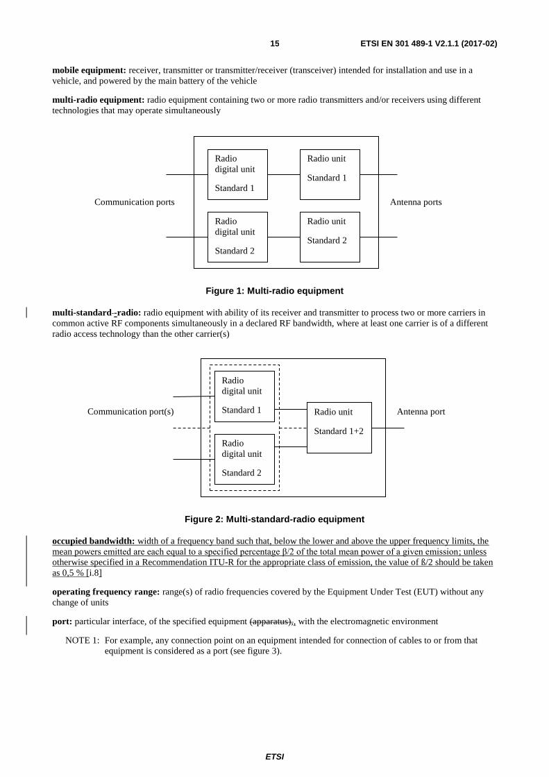
multi-radio equipment: radio equipment containing two or more radio transmitters and/or receivers using different
technologies that may operate simultaneously
Figure 1: Multi-radio equipment
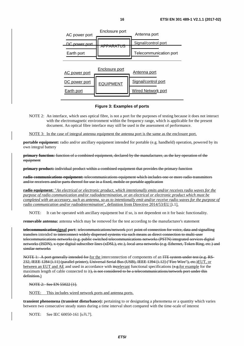
multi-standard -radio: radio equipment with ability of its receiver and transmitter to process two or more carriers in
common active RF components simultaneously in a declared RF bandwidth, where at least one carrier is of a different
radio access technology than the other carrier(s)
Figure 2: Multi-standard-radio equipment
occupied bandwidth: width of a frequency band such that, below the lower and above the upper frequency limits, the
mean powers emitted are each equal to a specified percentage β/2 of the total mean power of a given emission; unless
otherwise specified in a Recommendation ITU-R for the appropriate class of emission, the value of ß/2 should be taken
as 0,5 % [i.8]
operating frequency range: range(s) of radio frequencies covered by the Equipment Under Test (EUT) without any
change of units
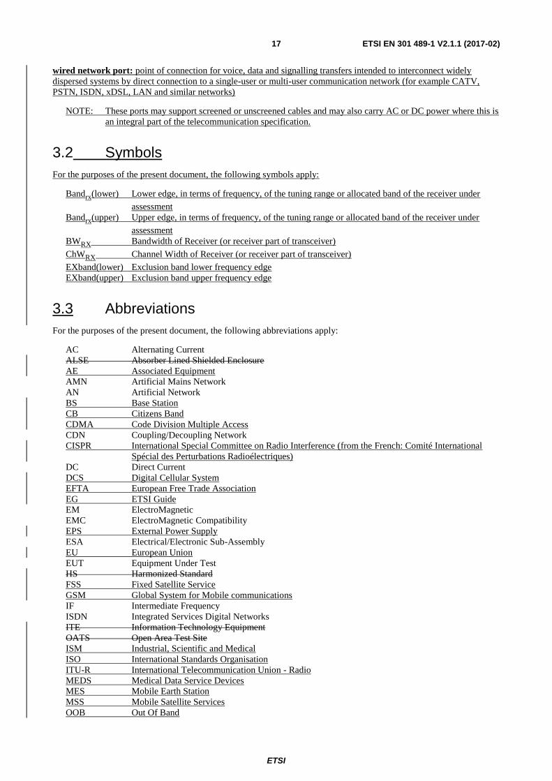
port: particular interface, of the specified equipment (apparatus),, with the electromagnetic environment
NOTE 1: For example, any connection point on an equipment intended for connection of cables to or from that
equipment is considered as a port (see figure 3).
Radio
digital unit
Standard 1 Radio unit
Standard 1+2
Radio
digital unit
Standard 2
Antenna port Communication port(s)
Radio
digital unit
Standard 1
Radio unit
Standard 1
Radio unit
Standard 2
Radio
digital unit
Standard 2
Antenna ports Communication ports
ETSI
ETSI EN 301 489-1 V2.1.1 (2017-02) 16
Figure 3: Examples of ports
NOTE 2: An interface, which uses optical fibre, is not a port for the purposes of testing because it does not interact
with the electromagnetic environment within the frequency range, which is applicable for the present
document. An optical fibre interface may still be used in the assessment of performance.
NOTE 3: In the case of integral antenna equipment the antenna port is the same as the enclosure port.
portable equipment: radio and/or ancillary equipment intended for portable (e.g. handheld) operation, powered by its
own integral battery
primary function: function of a combined equipment, declared by the manufacturer, as the key operation of the
equipment
primary product: individual product within a combined equipment that provides the primary function
radio communications equipment: telecommunications equipment which includes one or more radio transmitters
and/or receivers and/or parts thereof for use in a fixed, mobile or portable application
radio equipment: "An electrical or electronic product, which intentionally emits and/or receives radio waves for the
purpose of radio communication and/or radiodetermination, or an electrical or electronic product which must be
completed with an accessory, such as antenna, so as to intentionally emit and/or receive radio waves for the purpose of
radio communication and/or radiodetermination", definition from Directive 2014/53/EU [i.1].
NOTE: It can be operated with ancillary equipment but if so, is not dependent on it for basic functionality.
removable antenna: antenna which may be removed for the test according to the manufacturer's statement
telecommunicationsignal port: telecommunications/network port point of connection for voice, data and signalling
transfers intended to interconnect widely dispersed systems via such means as direct connection to multi-user
telecommunications networks (e.g. public switched telecommunications networks (PSTN) integrated services digital
networks (ISDN), x-type digital subscriber lines (xDSL), etc.), local area networks (e.g. Ethernet, Token Ring, etc.) and
similar networks
NOTE 1: A port generally intended for for the interconnection of components of an ITE system under test (e.g. RS-
232, IEEE 1284 [i.11] (parallel printer), Universal Serial Bus (USB), IEEE 1394 [i.12] ("Fire Wire"), etc.)EUT, or
between an EUT and AE and used in accordance with itsrelevant functional specifications (e.g.for example for the
maximum length of cable connected to it), is not considered to be a telecommunications/network port under this
definition.)
NOTE 2: See EN 55022 [1].
NOTE: This includes wired network ports and antenna ports.
transient phenomena (transient disturbance): pertaining to or designating a phenomena or a quantity which varies
between two consecutive steady states during a time interval short compared with the time-scale of interest
NOTE: See IEC 60050-161 [i.7i.7].
DC power port
AC power portEnclosure port
Antenna port
Signal/control portAPPARATUS
Telecommunication portEarth port
DC power port
AC power port Enclosure port
Antenna port
Signal/control port EQUIPMENT
Wired Network port Earth port
ETSI
ETSI EN 301 489-1 V2.1.1 (2017-02) 17
wired network port: point of connection for voice, data and signalling transfers intended to interconnect widely
dispersed systems by direct connection to a single-user or multi-user communication network (for example CATV,
PSTN, ISDN, xDSL, LAN and similar networks)
NOTE: These ports may support screened or unscreened cables and may also carry AC or DC power where this is
an integral part of the telecommunication specification.
3.2 Symbols
For the purposes of the present document, the following symbols apply:
Bandrx(lower) Lower edge, in terms of frequency, of the tuning range or allocated band of the receiver under
assessment
Bandrx(upper) Upper edge, in terms of frequency, of the tuning range or allocated band of the receiver under
assessment
BWRX Bandwidth of Receiver (or receiver part of transceiver)
ChWRX Channel Width of Receiver (or receiver part of transceiver)
EXband(lower) Exclusion band lower frequency edge
EXband(upper) Exclusion band upper frequency edge
3.3 Abbreviations
For the purposes of the present document, the following abbreviations apply:
AC Alternating Current
ALSE Absorber Lined Shielded Enclosure
AE Associated Equipment
AMN Artificial Mains Network
AN Artificial Network
BS Base Station
CB Citizens Band
CDMA Code Division Multiple Access
CDN Coupling/Decoupling Network
CISPR International Special Committee on Radio Interference (from the French: Comité International
Spécial des Perturbations Radioélectriques)
DC Direct Current
DCS Digital Cellular System
EFTA European Free Trade Association
EG ETSI Guide
EM ElectroMagnetic
EMC ElectroMagnetic Compatibility
EPS External Power Supply
ESA Electrical/Electronic Sub-Assembly
EU European Union
EUT Equipment Under Test
HS Harmonized Standard
FSS Fixed Satellite Service
GSM Global System for Mobile communications
IF Intermediate Frequency
ISDN Integrated Services Digital Networks
ITE Information Technology Equipment
OATS Open Area Test Site
ISM Industrial, Scientific and Medical
ISO International Standards Organisation
ITU-R International Telecommunication Union - Radio
MEDS Medical Data Service Devices
MES Mobile Earth Station
MSS Mobile Satellite Services
OOB Out Of Band
ETSI
ETSI EN 301 489-1 V2.1.1 (2017-02) 18
PLC PowerLine Communications
PMR Private Mobile Radio
PSTN Public Switched Telecommunications Networks
RF Radio Frequency
rms root mean square
USB Universal Serial Bus
ROMES Receive Only Mobile Earth Station
SRD Short Range Device
SW SoftWare
TV Television
UE User Equipment
UTRA UMTS Terrestrial Radio Access
UWB Ultra Wide Band
VHF Very High Frequency
xDSL x-type Digital Subscriber Line
4 Test conditions
4.1 General
The equipment shall be tested under normal test conditions according to the relevant product and basic standards or to
the information accompanying the equipment, which are within the manufacturers declared range of humidity,
temperature and supply voltage. The test conditions shall be recorded in the test report.
The test configuration and mode of operation shall represent the intended use and shall be recorded in the test report.
For emission and immunity tests, specific product related information on the test modulation, test conditions and tests
arrangements, etc., are found in the relevant part of ETSI EN 301 489 series [i.13] dealing with the particular type of
radio equipment.].
4.2 Arrangements for test signals
4.2.0 General
Adequate measures shall be taken to avoid the effect of immunity test signals on both the measuring equipment and the
signal sources for the wanted signals located outside the test environment.
4.2.1 Arrangements for test signals at the input of transmitters
The signal source providing the transmitter under test with the modulation signal for the normal test modulation shall be
located outside the test environment, unless the transmitter is modulated by its own internal source, see the relevant part
of ETSI EN 301 489 series [i.13i.13].
The transmitter shall be modulated with normal test modulation, by an internal or external signal source capable of
delivering the normal test modulation as specified in the relevant part of ETSI EN 301 489 series [i.13i.13].
4.2.2 Arrangements for test signals at the RF output of transmitters
The measuring equipment for the wanted RF output signal from the transmitter under test shall be located outside the
test environment.
For transmitters with an integral antenna, the wanted RF output signal to establish a communication link shall be
delivered from the EUT to an antenna located within the test environment. This antenna shall be connected to the
external measuring equipment by a coaxial cable.
ETSI
ETSI EN 301 489-1 V2.1.1 (2017-02) 19
For transmitters with a removablean antenna connector, the wanted RF output signal to establish a communication link
shall be delivered from the antenna connector to the external measuring equipment by a shielded transmission line, such
as a coaxial cable. Adequate measures shall be taken to minimize the effect of unwanted common mode currents on the
external conductor of the transmission line at the point of entry to the transmitter.
Unless otherwise specified in the relevant part of ETSI EN 301 489 series [i.13] for the particular type of radio
equipment, the level of the wanted RF output signal in transmit mode of operation shall be set to the maximum rated RF
power for the EUT, modulated with the normal test modulation.
4.2.3 Arrangements for test signals at the RF input of receivers
The signal source providing the receiver under test with the wanted RF input signal shall be located outside the test
environment.
The signal source shall be modulated with normal test modulation as specified in the relevant part of ETSI EN 301 489
series [i.13] for the particular type of radio equipment.
For receivers with an integral antenna, the wanted RF input signal to establish a communication link shall be presented
to the EUT from an antenna located within the test environment. This antenna shall be connected to the external RF
signal source by a coaxial cable.
For receivers with a removablean antenna connector, the wanted RF input signal to establish a communication link shall
be presented to the antenna connector of the EUT by a shielded transmission line, such as a coaxial cable. The
transmission line shall be connected to the external RF signal source. Adequate measures shall be taken to minimize the
effect of unwanted common mode currents on the external conductor of the shielded transmission line at the point of
entry to the receiver.
Unless otherwise specified in the part of ETSI EN 301 489 series [i.13] relevant for the particular type of radio
equipmenttechnology, the level of the wanted RF input signal shall be set to be approximately 40 dB above the
minimum level necessary to achieve a receiver performance which meets the relevant specified performance criteria,
measured while the power amplifiers generating the EM disturbance are switched on, but without excitation. This
increased level of the wanted RF input signal is expected to represent a normal operation signal level and should be
sufficient to avoid the broadband noise from the power amplifiers generating the EM disturbance from influencing the
measurement.
4.2.4 Arrangements for test signals at the output of receivers
The measuring equipment for the output signal from the receiver under test shall be located outside the test
environment.
For receivers with an analogue speech output the audio output from the acoustic transducer should be coupled via an
electrically non-conductive acoustic tube to an external audio distortion meter or other appropriate measuring
equipment outside of the test environment. Where it is not practical to use an electrically non-conductive acoustic tube,
then other means of connecting the receiver output signal to the external audio distortion meter or other measuring
equipment shall be provided and recorded in the test report.
For receivers with a non-speech output the output signal shall be coupled via an electrically non-conductive means to
the external measuring equipment outside the test environment (e.g. a camera to read a display). If the receiver has an
output connector or port providing the wanted output signal, then this port shall be used via a cable, consistent with the
standard cable used in normal operation, connected to the external measuring equipment outside the test environment.
The measuring equipment may be supplied by the manufacturer.
Precautions shall be taken to ensure that any effect on the test due to the coupling means is minimized.
4.2.5 Arrangements for testing transmitter and receiver together (as a system)
Transmitters and receivers may be tested for immunity as a system when combined as a transceiver or the combined
equipment is of a size which allows simultaneous testing.. In this case the transceiver or transmitter and receiver shall
be located inside the test environment and shall be exposed simultaneously to the immunity test signals.
ETSI
ETSI EN 301 489-1 V2.1.1 (2017-02) 20
For transceivers or transmitters and receivers operating at the same frequency, the wanted output signal of the
transmitter may be used via a suitable attenuator and applied to the input of the receiver as the wanted input signal.
For transceivers or transmitters and receivers operating at different frequencies in duplex mode the arrangements are
defined in the product part of ETSI EN 301 489 series [i.13i.13] relevant for the particular type of radio equipment.
4.3 RF exclusion band of radio communications equipment
4.3.1 General
The RF exclusion band applies to radio bands shall be derived using the methodologies detailed in clauses 4.3.2 and
4.3.3 of the present document. These are equipment with an operating frequency up to 2,7 GHz, or for equipment
operating above 2,7 GHz, but whose RF bandwidth extends to a frequency below 2,7 GHz.
For equipment operating at frequencies above 2,7 GHz and whose RF bandwidth does not extend to a frequency below
2,7 GHz, there is no exclusion band.
This exclusion band is always product dependent and defined in the relevant part of ETSI EN 301 489 series [i.13]
dealing with the particular type of radio equipment.], except where the present document is used on a standalone basis.
Whenever an exclusion band is applied, the specific frequency range(s) excluded from assessment shall be detailed in
the technical documentation.
4.3.2 Exclusion band for transmitters or the transmitter part of transceivers
4.3.2.1 General
Exclusion bands shall not be applied when measuring transmitters in standby mode.
4.3.2.2 Channelized Equipment
For channelized equipment the exclusion band shall extend 250 % of the channel width either side of the transmitter
centre frequency.
NOTE: Exclusion band of 250 % is based on the ITU Radio Regulations [i.8], as the boundary between OOB and
Spurious Domain.
4.3.2.3 Non-Channelized Equipment
For non-channelized equipment the exclusion band shall extend 250 % of the occupied bandwidth either side of the
transmitter centre frequency.
NOTE: Exclusion band of 250 % is based on the ITU Radio Regulations [i.8], as the boundary between OOB and
Spurious Domain.
4.3.3 Exclusion band for receivers or the receiver part of transceivers
4.3.3.1 Applicability
Exclusion bands are not applied when testing emissions of receivers or receiver part of transceivers.
4.3.3.2 Channelized Equipment
For channelized equipment the exclusion band shall be calculated by using the following formulae:
For the lower edge for the exclusion band:
EXband(lower) = BandRX(lower) – nChWRX
ETSI
ETSI EN 301 489-1 V2.1.1 (2017-02) 21
and for the upper edge of the exclusion band:
EXband(upper) = BandRX(upper) + nChWRX
Where n = number of channel widths required for exclusion band.
For equipment that support multiple channel widths the Channel Width used should be the widest support by the EUT.
Where the present document is being used in a stand-alone basis (i.e. with no reference to other relevant radio
technology parts of ETSI EN 301 489 series [i.13]), the value of n shall be 1.
4.3.3.3 Non-Channelized Equipment
For non-channelized equipment the exclusion band shall be calculated by using the following formula:
For the lower edge for the exclusion band:
EXband(lower) = BandRX(lower) – nBWRX
and for the upper edge of the exclusion band:
EXband(upper) = BandRX(upper) + nBWRX
Where n = multiple of whole bandwidths required to define exclusion band.
Bandwidth of Receiver is the occupied bandwidth of the corresponding transmitter signal.
Where the present document is being used in a stand-alone basis (i.e. with no reference to other relevant radio
technology parts of ETSI EN 301 489 series [i.13]), the value of n shall be 1.
4.4 Narrow band responses of receivers or receivers which are part of transceivers
Responses on receivers or the receiver part of (duplex) transceivers occurring during the immunity tests at discrete
frequencies which are narrow band responses (spurious responses), are identified by the following method.
If during the test the immunity RF test signal (see clauses 9.2 and 9.5) causes non-compliance of the receiver with the
specified performance criteria (see clause 6), it is necessary to establishevaluate whether this non-compliance is due to a
narrow band response or a wideband phenomenon. Therefore, the frequency of the test signal is increased by an amount
equal to twice the nominal 6 dB bandwidth of the IF filter immediately preceding the demodulator of the receiver, or if
appropriate, the bandwidth over which the apparatusequipment is intended to operate, as declared by the manufacturer.
The test is repeated with the frequency of the test signal decreased by the same amount.
If the receiver is then in either or both frequency offset cases in compliance with the specified performance criteria, the
response is considered as a narrow band response.
If the receiver still does not comply with the specified performance criteria, this may be due to the fact that the offset
has made the frequency of the unwanted signal correspond to the frequency of another narrow band response. Under
these circumstances the procedure is repeated with an increase and decrease of the frequency of the test signal adjusted
two and a half times the bandwidth referred to above.
If the receiver still does not comply with the specified performance criteria in either or both frequency offset cases, the
phenomena is considered wide band and therefore an EMC problem and the equipment fails the test.
For immunity tests, narrow band responses shall be disregarded.
Particular performance criteria typical for the relevant type of EUT and information about any product type dependent
nominal frequency offset to be used for the identification of narrowband responses can be found in the part of ETSI
EN 301 489 series [i.13i.13] dealing with the particular type of radio equipment.
Where no narrow band responses of receivers are permitted, this shall be stated within the part of ETSI
EN 301 489 series [i.13i.13] dealing with particular type of radio equipment.
ETSI
ETSI EN 301 489-1 V2.1.1 (2017-02) 22
4.5 Normal test modulation
For the purpose of EMC tests, the transmitter under test shall be modulated according to the normal test modulation
specified in the relevant part of ETSI EN 301 489 series [i.13] dealing with the particular type of radio equipment.].
For the purpose of EMC tests, the receiver under test shall be provided with a wanted RF input signal modulated
according to the normal test modulation specified in the relevant part of ETSI EN 301 489 series [i.13] dealing with the
particular type of radio equipment.].
5 Performance assessment
5.1 General
The manufacturer shall at the time of submission of the equipment for test, supply the following information to be
recorded in the test report:
the primary functions of the radio equipment to be assessed during and after the EMC exposure;
the intended functions of the radio equipment which shall be in accordance with the documentation
accompanying the equipment;
the user control functions and stored data that are required for normal operation and the method to be used to
assess whether these have been lost after the EMC exposure;
the type of modulation, the characteristics of the transmission used for testing (random bit stream, message
format, etc.) and the necessary test equipment delivered to enable the assessment of the EUT;
the ancillary equipment to be combined with the radio equipment for testing (where applicable);
an exhaustive list of ports, with the maximum cable lengths allowed, classified as either power or
telecommunication/signal/control. Power ports shall further be classified as AC or DC power;
the bandwidth of the IF filter immediately preceding the demodulator or equivalent system bandwidth;
the method to be used to verify that a communication link is established and maintained (if appropriate);
the operating frequency bands over which the equipment is intended to operate;
any equipment thermal limitation which prevent continuous testing of the EUT;
the environment(s) in which the equipment is intended to be used.;
the occupied bandwidth of the corresponding transmitter signal for non-channelized equipment.
If additional product related information is required, these can be found in the relevant part of ETSI EN 301 489 series
[i.13] dealing with the particular type of radio equipment.].
If the present document is used on a stand alone basis to demonstrate presumption of conformity to European Directive
1999/5/EC2014/53/EU [i.1] as a specific radio part of the standard could not be identified for a particular type of radio
equipment, then the manufacturer shall at the time of submission of the equipment for test, supply the following
information to be recorded in the test report:
test conditions, clause 4;
the value of n used in clause 4.3 used to determine the exclusion bands;
performance assessment, clause 5;
performance criteria, clause 6.
ETSI
ETSI EN 301 489-1 V2.1.1 (2017-02) 23
5.2 Equipment which can provide a continuous communication link
For radio equipment of non-specialized nature or for radio equipment tested in combination with ancillary equipment,
the normal test modulation, test arrangements, etc., shall apply.
5.3 Equipment which does not provide a continuous communication link
For radio equipment which does not provide a continuous communication link and/or ancillary equipment intended to
be tested on a stand-alone basis, the manufacturer shall specify the permissible minimum level of performance or
degradation of performance during and/or after the EMC exposure.
The manufacturer shall furthermore define the test method(s) for the assessment of the actual level of performance or
degradation of performance during and/or after the EMC exposure. Under these circumstances the manufacturer shall
additionally provide the following information also for inclusion in the test report:
the primary functions of the relevant type of the EUT during and after EMC stress;
the intended functions of the relevant type of the EUT which shall be in accordance with the documentation
accompanying the equipment;
suitable pass/fail criteria for the relevant type of the EUT;
the method of monitoring the actual level of performance and/or the actual degradation of performance of the
EUT.;
the dwell time of the test phenomena at each frequency shall not be less than the time necessary for the EUT to
be exercised and to be able to respond.
The assessment of the actual performance or its degradation which is carried out during and/or after the EMC exposure,
shall be simple, but at the same time give adequate proof that the primary functions of the equipment are operational.
5.4 Ancillary equipment
At the manufacturer's discretion ancillary equipment may be tested and assessed:
applying the provisions of the present document:
- separately to the ancillary equipment; or
- to the combination of ancillary and radio equipment;
applying another appropriate EMC standard.
In each case, compliance enables the ancillary equipment to be used with different receivers, transmitters or
transceivers.
5.5 Equipment classification
For the purpose of the EMC performance assessment in the present document, the radio equipment and/or associated
ancillary equipment under test shall be classified into one of the following three classes:
equipment for fixed use (e.g. base station equipment); or
equipment for vehicular use (e.g. mobile equipment); or
equipment for portable use (e.g. portable equipment);
taking into account the definitions in clause 3.1.
ETSI
ETSI EN 301 489-1 V2.1.1 (2017-02) 24
This classification determines the extent of applicable EMC tests. However, the following instructions shall also apply
to multiple use radio and/or ancillary equipment:
radio and/or ancillary equipment for portable use or combinations thereof declared as capable of being
powered for intended use by the main battery of a vehicle shall additionally be considered as equipment for
vehicular use;
radio and/or ancillary equipment for portable or vehicular use or combinations thereof declared as capable of
being powered for intended use by an AC mains or DC network shall additionally be considered as equipment
for fixed use.
Subsequently, for multiple use radio and/or ancillary equipment more than one set of equipment test requirements listed
in tables 1 and 2 has to be taken into account.
Additionally radio equipment when integrated within a host equipment shall meet the requirements of the present
document.
6 Performance criteria
6.0 Introduction
The performance criteria are used to take a decision on whether a radio equipment passes or fails immunity tests.
For the purpose of the present document four categories of performance criteria apply:
performancePerformance criteria for continuous phenomena applied to transmitters; and receivers
performancePerformance criteria for transient phenomena applied to transmitters; and receivers
performancePerformance criteria for equipment which does not provide a continuous phenomena applied to
receivers;communication link
performancePerformance criteria for transient phenomena applied to receivers.ancillary equipment tested on a
stand alone basis
Normally, the performance criteria depend on the type of radio equipment. Thus, the present document only contains
general performance criteria commonly used for the assessment of radio equipment. More specific and product-related
performance criteria for a dedicated type of radio equipment may be found in the part of ETSI EN 301 489 series [i.13]
dealing with the particular type of radio equipment.
6.1 Performance criteria for continuous phenomena applied to transmitters and receivers
If no further details are given in the relevant part of ETSI EN 301 489 series [i.13] dealing with the particular type of
radio equipment, the following general performance criteria for continuous phenomena shall apply.
During and after the test, the apparatusequipment shall continue to operate as intended. No degradation of performance
or loss of function is allowed below a permissible performance level specified by the manufacturer when the
apparatusequipment is used as intended. In some cases this permissible performance level may be replaced by a
permissible loss of performance.
During the test the EUT shall not unintentionally transmit or change its actual operating state and stored data.
If the minimum performance level or the permissible performance loss is not specified by the manufacturer, then either
of these may be deduced from the product description and documentation and what the user may reasonably expect
from the apparatusequipment if used as intended.
ETSI
ETSI EN 301 489-1 V2.1.1 (2017-02) 25
6.2 Performance criteria for transient phenomena applied to transmitters and receivers
If no further details are given in the relevant part of ETSI EN 301 489 series [i.13] dealing with the particular type of
radio equipment, the following general performance criteria for transient phenomena shall apply.
For surges applied to symmetrically operated wired network ports intended to be connected directly to outdoor lines the
following criteria applies:
For products with only one symmetrical port intended for connection to outdoor lines, loss of function is
allowed, provided the function is self-recoverable, or can be restored by the operation of the controls by the
user in accordance with the manufacturer's instructions. A SW reboot is not allowed. Information stored in
non-volatile memory, or protected by a battery backup, shall not be lost.
For products with more than one symmetrical port intended for connection to outdoor lines, loss of function on
the port under test is allowed, provided the function is self-recoverable. A SW reboot is not allowed.
Information stored in non-volatile memory, or protected by a battery backup, shall not be lost.
For all other ports the following applies:
After the test, the apparatusequipment shall continue to operate as intended. No degradation of performance or
loss of function is allowed below a permissible performance level specified by the manufacturer, when the
apparatusequipment is used as intended. In some cases this permissible performance level may be replaced by
a permissible loss of performance.
During the EMC exposure to an electromagnetic phenomenon, a degradation of performance is, however,
allowed. No change of the actual mode of operation (e.g. unintended transmission) or stored data is allowed.
If the minimum performance level or the permissible performance loss is not specified by the manufacturer,
then either of these may be deduced from the product description and documentation and what the user may
reasonably expect from the apparatusequipment if used as intended.
6.3 Performance criteria for equipment which does not provide a continuous communication link
For radio equipment which does not provide a continuous communication link, the performance criteria described in
clauses 6.1 and 6.2 are not appropriate, thenin these cases the manufacturer shall declare, for inclusion in the test report,
his own specification for an acceptable level of performance or degradation of performance during and/or after the
immunity tests. The performance specification shall be included in the product description and documentation. The
related specifications set out in clause 5.3 have also to be taken into account.
The performance criteria specified by the manufacturer shall give the same degree of immunity protection as called for
in clauses 6.1 and 6.2.
6.4 Performance criteria for ancillary equipment tested on a stand alone basis
If ancillary equipment is intended to be tested on a stand alone basis, the performance criteria described in clauses 6.1
and 6.2 are not appropriate, thenin these cases the manufacturer shall declare, for inclusion in the test report, his own
specification for an acceptable level of performance or degradation of performance during and/or after the immunity
tests. The performance specification shall be included in the product description and documentation. The related
specifications set out in clause 5.3 have also to be taken into account.
The performance criteria specified by the manufacturer shall give the same degree of immunity protection as called for
in clauses 6.1 and 6.2.
7 Applicability overview tables
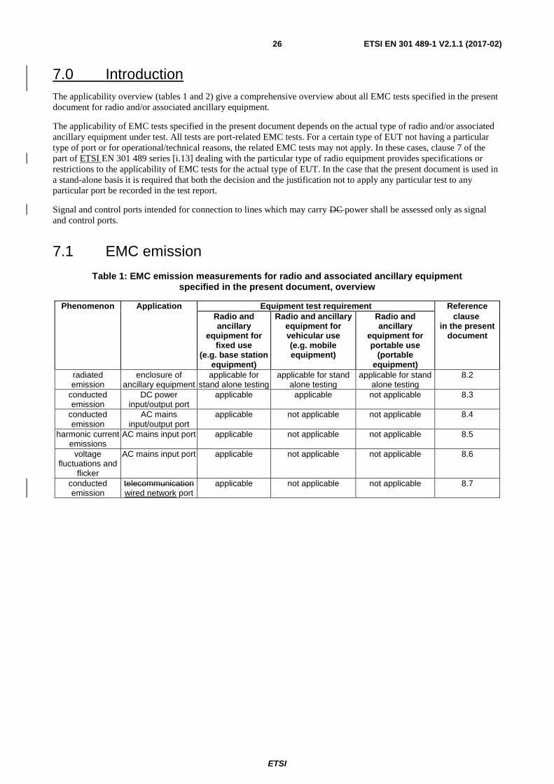
ETSI
ETSI EN 301 489-1 V2.1.1 (2017-02) 26
7.0 Introduction
The applicability overview (tables 1 and 2) give a comprehensive overview about all EMC tests specified in the present
document for radio and/or associated ancillary equipment.
The applicability of EMC tests specified in the present document depends on the actual type of radio and/or associated
ancillary equipment under test. All tests are port-related EMC tests. For a certain type of EUT not having a particular
type of port or for operational/technical reasons, the related EMC tests may not apply. In these cases, clause 7 of the
part of ETSI EN 301 489 series [i.13] dealing with the particular type of radio equipment provides specifications or
restrictions to the applicability of EMC tests for the actual type of EUT. In the case that the present document is used in
a stand-alone basis it is required that both the decision and the justification not to apply any particular test to any
particular port be recorded in the test report.
Signal and control ports intended for connection to lines which may carry DC power shall be assessed only as signal
and control ports.
7.1 EMC emission
Table 1: EMC emission measurements for radio and associated ancillary equipment specified in the present document, overview
Phenomenon Application Equipment test requirement Reference
Radio and ancillary
equipment for fixed use
(e.g. base station equipment)
Radio and ancillary equipment for vehicular use (e.g. mobile equipment)
Radio and ancillary
equipment for portable use
(portable equipment)
clause in the present
document
radiated emission
enclosure of ancillary equipment
applicable for stand alone testing
applicable for stand alone testing
applicable for stand alone testing
8.2
conducted emission
DC power input/output port
applicable applicable not applicable 8.3
conducted emission
AC mains input/output port
applicable not applicable not applicable 8.4
harmonic current emissions
AC mains input port applicable not applicable not applicable 8.5
voltage fluctuations and
flicker
AC mains input port applicable not applicable not applicable 8.6
conducted emission
telecommunicationwired network port
applicable not applicable not applicable 8.7
ETSI
ETSI EN 301 489-1 V2.1.1 (2017-02) 27
7.2 Immunity
Table 2: Immunity tests for radio and associated ancillary equipment specified in the present document, overview
Phenomenon Application Equipment test requirement Reference
Radio and ancillary
equipment for fixed use
(e.g. base station equipment)
Radio and ancillary equipment for vehicular use (e.g. mobile equipment)
Radio and ancillary
equipment for portable use
(portable equipment)
clause in the present
document
RF electromagnetic
field (80 MHz to 16 000 MHz
and 1 400 MHz to 2 700 MHz)
enclosure port applicable applicable applicable 9.2
electrostatic discharge
enclosure applicable not applicable applicable 9.3
fast transients common mode
signal, telecommunicationwired network and control ports, DC
and AC power ports
applicable not applicable not applicable 9.4
RF common mode 0,15 MHz
to 80 MHz
signal, telecommunicationwired network and control ports, DC
and AC power ports
applicable applicable not applicable 9.5
transients and surges
DC power input ports
not applicable applicable not applicable 9.6
voltage dips and interruptions
AC mains power input ports
applicable not applicable not applicable 9.7
surges, line to line and line to
ground
AC mains power input ports,
telecommunicationwired network
ports
applicable not applicable not applicable 9.8
Tables 3 and 4: Void
8 Methods of measurement and limits for EMC emissions
8.1 Test configuration
This clause defines the requirements for test configurations:
measurements shall be made in the operational mode producing the largest emission in the frequency band
being investigated consistent with normal applications;
the equipment shall be configured in a manner which is representative for normal/typical operation, where
practical;
where radio equipment is provided with an integral antenna, it shall be tested with the antenna fitted in a
manner typical of normal intended use, unless declared as a removable antenna;
ETSI
ETSI EN 301 489-1 V2.1.1 (2017-02) 28
if the equipment is part of a system, or can be connected to ancillary equipment, then it shall be acceptable to
test the equipment while connected to the minimum representative configuration of ancillary equipment
necessary to exercise the ports;
if the equipment has a large number of ports, then a sufficient number shall be selected to simulate actual
operational conditions and to ensure that all the different types of terminationports are covered;
ports, which in normal operation are connected, shall be connected to an ancillary equipment or to a
representative piece of cable terminated to simulate the impedance of the ancillary equipment. RF input/output
ports shall be correctly terminated;
the configuration and mode of operation during the measurements shall be precisely noted in the test report.
8.2 Enclosure port of ancillary equipment measured on a stand alone basis
8.2.1 General
This test is only applicable to ancillary equipment not incorporated in the radio equipment and intended to be measured
on a stand-alone basis, as declared by the manufacturer. This test shall be performed on a representative configuration
of the ancillary equipment.
This test is not applicable for ancillary equipment incorporated in the radio equipment, or for ancillary equipment
intended to be measured in combination with the radio equipment. In these cases the requirements of the relevant
product standard for the effective use of the radio spectrum shall apply.
Product related conditions for combined testing of radio and ancillary equipment may be contained in the relevant part
of ETSI EN 301 489 series [i.13] dealing with the particular type of radio equipment.].
8.2.1 Definition
This test assesses the ability of ancillary equipment to limit their internallevel of radiated electromagnetic noise from
being radiated from the enclosure of ancillary equipment.
8.2.2 Test method
The test method shall be in accordance with CENELEC EN 5502255032 [1].
8.2.3 Limits
The ancillary equipment shall meet the class B limits given in CENELEC EN 55022 55032 [1].
Alternatively, for ancillary equipment intended to be used inexclusively in an industrial environment or
telecommunication centers onlycentres, the class A limits given in CENELEC EN 5502255032 [1] may be used.
8.3 DC power input/output ports
8.3.1 General
This test is applicable for radio equipment and ancillary equipment for fixed use that may have DC cables longer than
3 m (see clause 5.1 - manufacturer's declaration) and for vehicular use irrespective of cable length.
If the DC power cable of the radio and/or the ancillary equipment is less than or equal to 3 m in length, and intended for
direct connection to a dedicated AC/DC power supply, then the measurement shall be performed on the AC power input
port of that power supply as specified in clause 8.4. If the DC power cable is longer than 3 m, then the measurement
shall additionally be performed on the DC power port of the radio and/or ancillary equipment.
ETSI
ETSI EN 301 489-1 V2.1.1 (2017-02) 29
If the DC power cable between the mobile radio and/or ancillary equipment and the dedicated DC/DC power converter
is less than or equal to 3 m in length, then the measurement can be limited to the DC power input port of that power
converter only. If this DC power cable is longer than 3 m, then the measurement shall additionally be performed on the
DC power port of the mobile radio and/or ancillary equipment.
This test shall be performed on a representative configuration of the radio equipment, the associated ancillary
equipment, or a representative configuration of the combination of radio and ancillary equipment.
8.3.1 Definition
This test assesses the abilitylevel of the EUT to limit its internalinternally generated electrical noise from being present
on the DC power input/output ports.
8.3.2 Test method
The test method shall be in accordance with EN 55022 [1]. For radio and ancillary equipment for fixed use, the
Artificial Mains Networks (AMN) as specified in EN 55022 [1] shall be used and be connected to a DC power source.
For mobile radio and ancillary equipment intended to be connected to the vehicle's onboard DC mains, an Artificial
Network (AN) as specified in CISPR 25 [1010] shall be used and be connected to a DC power source.
For all other equipment the test method for AC mains power port specified in CENELEC EN 55032 [1] shall be used.
The measurement frequency range extends from 150 kHz to 30 MHz. When the EUT is a transmitter operating at
frequencies below 30 MHz, then the exclusion band for transmitters applies (see clause 4.3) for measurements in the
transmit mode of operation.
For emission measurements on DC output ports the relevant port shall be connected via an AMN/AN to a load drawing
the rated current of the source.
8.3.3 Limits
The equipment shall meet the limits below including the average limit and the quasi-peak limit when using,
respectively, an average detector receiver and a quasi-peak detector receiver and measured in accordance with the
method described in clause 8.3.2. If the average limit is met when using a quasi-peak detector, the equipment shall be
deemed to meet both limits and measurement with the average detector is unnecessary.
The equipment shall meet the limits shown in table 5.
Table 5: Limits for conducted emissions
Frequency range Limit (quasi-peak) (dBµV)
Limit (average) (dBµV)
0,15 MHz to 0,5 MHz 66 to 56 56 to 46
> 0,5 MHz to 5 MHz 56 46
> 5 MHz to 30 MHz 60 50
NOTE: The limit decreases linearly with the logarithm of the frequency in the range 0,15 MHz to 0,50 MHz.
Alternatively, for equipment intended to be used in an industrial environment or a telecommunication centres only, the
limits given in table 6 may be used.
Table 6: Limits for conducted emissions of equipment intended to be used in telecommunication centres onlyand industrial environment
Frequency range Limit (quasi-peak) (dBµV)
Limit (average) (dBµV)
0,15 MHz to 0,5 MHz 79 66
> 0,5 MHz to 30 MHz 73 60
ETSI
ETSI EN 301 489-1 V2.1.1 (2017-02) 30
8.4 AC mains power input/output ports
8.4.1 General
This test is applicable for radio equipment and/or ancillary equipment for fixed use powered by the AC mains.
This test shall be performed on a representative configuration of the radio equipment, the associated ancillary
equipment, or a representative configuration of the combination of radio and ancillary equipment.
This test shall be performed on a representative configuration of the radio equipment, the associated ancillary
equipment, or a representative configuration of the combination of radio and ancillary equipment.
8.4.1 Definition
This test assesses the abilitylevel of the EUT to limit its internalinternally generated electrical noise from being present
on the AC mains power input/output ports.
8.4.2 Test method
The test method shall be in accordance with CENELEC EN 5502255032 [1] and the Artificial Mains Networks (AMNs)
shall be connected to the AC mains power source.
The measurement frequency range extends from 150 kHz to 30 MHz. When the EUT is a transmitter operating at
frequencies below 30 MHz, then the exclusion band for transmitters applies (see clause 4.3) for measurements in the
transmit mode of operation.
For emission measurements on AC output ports of the EUT the relevant port shall be connected via an AMN to a load
drawing the rated current of the source. In case where the AC output port is directly connected (or via a circuit breaker)
to the AC power input port of the EUT the AC power output port need not to be tested.
8.4.3 Limits
8.4.3.1 General
The equipment shall meet the limits below including the average limit and the quasi-peak limit when using,
respectively, an average detector receiver and a quasi-peak detector receiver and measured in accordance with the
method described in clause 8.4.2. If the average limit is met when using a quasi-peak detector, the equipment shall be
deemed to meet both limits and measurement with the average detector is unnecessary.
8.4.3.2 AC Power port used for power supply only
The equipment shall meet the class B limits given in CENELEC EN 5502255032 [Error! Reference source not
found.].
Alternatively, for equipment intended to be used in an industrial environment or a telecommunication centres
onlycentre, the class A limits given in CENELEC EN 55022 55032 [1] may be used.
8.4.3.3 AC power input port also used for PLC Communications
Where the A.C power port of the equipment is also used for PLC communication up to 30 MHz then the EUT shall
comply with the requirements of CENELEC EN 50561-1 [14] instead of those in clause 8.4.3.2 of the present
document.
Where the A.C power port of the equipment is also used for PLC communication above 30 MHz then the EUT shall
comply with the requirements of CENELEC EN 50561-3 [13] instead of those in clause 8.4.3.2 of the present
document.
ETSI
ETSI EN 301 489-1 V2.1.1 (2017-02) 31
8.5 Harmonic current emissions (AC mains input port)
The appropriate requirements of CENELEC EN 61000--3--2/A1 [15] for harmonic current emission apply for
equipment covered by the scope of the present document with an input current up to and including 16A per phase. For
equipment with an input current of greater than 16A per phase CENELEC EN 61000-3-12 [1111] applies.
8.6 Voltage fluctuations and flicker (AC mains input port)
The appropriate requirements of CENELEC EN 61000--3--3 [9] for voltage fluctuations and flicker apply for
equipment covered by the scope of the present document with an input current up to and including 16A per phase. For
equipment with an input current of greater than 16A per phase EN 61000-3-11 [, if no conditional connection is needed.
Where a conditional connection is required then the requirements of CENELEC EN 61000-3-11 [12] appliesshall apply.
For equipment with an input current of greater than 16A up to and including 75A per phase CENELEC
EN 61000-3-11 [12] applies.
8.7 TelecommunicationWired network ports
8.7.1 General
This test is applicable for radio equipment and/or ancillary equipment for fixed use which have
telecommunicationwired network ports.
This test shall be performed on a representative configuration of the radio equipment, the associated ancillary
equipment, or a representative configuration of the combination of radio and ancillary equipment.
This test shall be performed on a representative configuration of the radio equipment, the associated ancillary
equipment, or a representative configuration of the combination of radio and ancillary equipment.
8.7.1 Definition
This test assesses the EUTlevel of unwanted emissionemissions present at the telecommunicationwired network ports.
8.7.2 Test method
The test method shall be in accordance with CENELEC EN 55022 55032 [1].
The measurement frequency range extends from 150 kHz to 30 MHz. When the EUT is a transmitter operating at
frequencies below 30 MHz, then the exclusion band for transmitters applies (see clause 4.3) for measurements in the
transmit mode of operation.
8.7.3 Limits
The telecommunication wired network ports shall meet the class B limits given in CENELEC EN 55022 55032 [1].
Alternatively, for equipment intended to be used exclusively in an industrial environment or a telecommunication
centres onlycentre, the class A limits given in CENELEC EN 55022 55032 [1] may be used.
9 Test methods and levels for immunity tests
9.1 Test configuration
This clause defines the requirements for test configurations:
ETSI
ETSI EN 301 489-1 V2.1.1 (2017-02) 32
the tests shall be made in the mode(s) of operation specified in clause 4 in the relevant part of the ETSI
EN 301 489 series [i.13i.13] dealing with the particular type of radio equipment;
the tests shall be carried out at a point within the specified normal operating environmental range and at the
rated supply voltage for the equipment;
if the equipment is part of a system, or can be connected to ancillary equipment, then it shall be acceptable to
test the equipment connected to the minimum representative configuration of ancillary equipment necessary to
exercise the ports;
where radio equipment is provided with an integral antenna, it shall be tested with the antenna fitted in a
manner typical of normal intended use, unless declared as a removable antenna;
for the immunity tests of ancillary equipment, without a separate pass/fail criteria, the receiver or transmitter
coupled to the ancillary equipment, shall be used to judge whether the ancillary equipment passes or fails;
if the equipment has a large number of ports, then a sufficient number shall be selected to simulate actual
operational conditions and to ensure that all the different types of termination are covered;
ports, which in normal operation are connected, shall be connected to an ancillary equipment or to a
representative piece of cable terminated to simulate the impedance of the ancillary equipment. RF input/output
ports shall be correctly terminated;
ports which are not connected to cables during normal intended operation, e.g. service connectors,
programming connectors, temporary connectors etc. shall not be connected to any cables for the purpose of
EMC testing. Where cables have to be connected to these ports, or interconnecting cables have to be extended
in length in order to exercise the Equipment Under Test (EUT), precautions shall be taken to ensure that the
evaluation of the EUT is not affected by the addition or extension of these cables;
the configuration and mode of operation during the tests shall be precisely noted in the test report.
9.2 Radio frequency electromagnetic field (80 MHz to 16 000 MHz and 1 400 MHz to 2 700 MHz)
This test is applicable for radio equipment and associated ancillary equipment.
This test shall be performed on a representative configuration of the radio equipment, the associated ancillary
equipment, or a representative configuration of the combination of radio and ancillary equipment.
9.2.1 DefinitionGeneral
This test is applicable for radio equipment and associated ancillary equipment.
This test shall be performed on a representative configuration of the radio equipment, the associated ancillary
equipment, or a representative configuration of the combination of radio and ancillary equipment.
This test assesses the ability of the EUT to operate as intended in the presence of a radio frequency electromagnetic
field disturbance.
9.2.2 Test method
The test method shall be in accordance with CENELEC EN 61000-4-3 [33].
The following requirements and evaluation of test results shall apply:
the test level shall be 3 V/m (measured unmodulated). The test signal shall be amplitude modulated to a depth
of 80 % by a sinusoidal audio signal of 1 000 Hz. If the wanted signal is modulated at 1 000 Hz, then an audio
signal of 400 Hz shall be used;
ETSI
ETSI EN 301 489-1 V2.1.1 (2017-02) 33
the test shall be performed over the frequency range 80 MHz to 16 000 MHz and 1 400 MHz to 2 700 MHz
with the exception of the exclusion band for transmitters, receivers and duplex transceivers (see clause 4), as
appropriate;
for receivers and transmitters the stepped frequency increments shall be 1 % frequency increment of the
momentary used frequency, unless specified otherwise in the relevant part of ETSI EN 301 489 series [i.13]
dealing with the relevant type of radio equipment;];
the dwell time of the test phenomena at each frequency shall not be less than the time necessary for the EUT to
be exercised and to be able to respond.
NOTE: Dwell time is product dependent.
further product related spot frequency tests may be specified in the relevant part of ETSI EN 301 489 series
[i.13] dealing with the particular type of radio equipment;];
responses on receivers occurring at discrete frequencies, which are narrow band responses, shall be
disregarded from the test (see clause 4);
the frequencies selected and used during the test shall be recorded in the test report.
9.2.3 Performance criteria
For transmitters the performance criteria for continuous phenomena for transmitters shall apply (see clause 6 of the
relevant part of EN 301 489 series [i.13] dealing with the particular type of radio equipment)..
For receivers the performance criteria for continuous phenomena for receivers shall apply (see clause 6 of the relevant
part of EN 301 489 series [i.13] dealing with the particular type of radio equipment)..
For ancillary equipment the pass/failure criteria supplied by the manufacturer (see clause 6.4) shall apply, unless the
ancillary equipment is tested in connection with a receiver or transmitter in which case the corresponding performance
criteria above shall apply.
9.3 Electrostatic discharge
This test is applicable for radio equipment and associated ancillary equipment.
This test shall be performed on a representative configuration of the radio equipment, the associated ancillary
equipment, or a representative configuration of the combination of radio and ancillary equipment.
9.3.1 DefinitionGeneral
This test is applicable for radio equipment and associated ancillary equipment.
This test shall be performed on a representative configuration of the radio equipment, the associated ancillary
equipment, or a representative configuration of the combination of radio and ancillary equipment.
This test assesses the ability of the EUT to operate as intended in the event of an electrostatic discharge.
9.3.2 Test method
The test method shall be in accordance with CENELEC EN 61000-4-2 [22].
For radio equipment and ancillary equipment the following requirements and evaluation of test results shall apply.
The test severity level for contact discharge shall be ±4 kV and for air discharge ±8 kV. All other details, including
intermediate test levels, are contained within CENELEC EN 61000-4-2 [22].
Electrostatic discharges shall be applied to all exposed surfaces of the EUT except where the user documentation
specifically indicates a requirement for appropriate protective measures (see CENELEC EN 61000-4-2 [22]).
ETSI
ETSI EN 301 489-1 V2.1.1 (2017-02) 34
9.3.3 Performance criteria
For transmitters the performance criteria for transient phenomena for transmitter shall apply (see clause 6 of the relevant
part of EN 301 489 series [i.13] dealing with the particular type of radio equipment)..
For receivers the performance criteria for transient phenomena for receivers shall apply (see clause 6 of the relevant part
of EN 301 489 series [i.13] dealing with the particular type of radio equipment)..
For ancillary equipment the pass/failure criteria supplied by the manufacturer (see clause 6.4) shall apply, unless the
ancillary equipment is tested in connection with a receiver or transmitter in which case the corresponding performance
criteria above shall apply.
9.4 Fast transients, common mode
9.4.1 General
This test shall be performed on the AC mains power port (if any) of radio equipment and associated ancillary
equipment.
This test shall be additionally performed on signal ports, telecommunicationwired network ports, control ports, and DC
power ports, of radio equipment and associated ancillary equipment, if the cables may be longer than 3 m.
Where this test is not carried out on any port because the manufacturer declares that it is not intended to be used with
cables longer than 3 m, a list of ports, which were not tested for this reason, shall be included in the test report.
This test shall be performed on a representative configuration of the radio equipment or a representative configuration
of the combination of radio and ancillary equipment.
This test assesses the ability of the EUT to operate as intended in the event of fast transients present on one of the
input/output ports.
9.4.2 Test method
Where this test is not carried out on any port because the manufacturer declares that it is not intended to be used with
cables longer than 3 m, a list of ports, which were not tested for this reason, shall be included in the test report.
This test shall be performed on a representative configuration of the radio equipment or a representative configuration
of the combination of radio and ancillary equipment.
9.4.1 Definition
This test assesses the ability of the EUT to operate as intended in the event of fast transients present on one of the
input/output ports.
9.4.2 Test method
The test method shall be in accordance with CENELEC EN 61000-4-4 [44].
The following requirements and evaluation of test results shall apply:
the test level for signal ports, telecommunicationwired network ports, (excluding xDSL), and control ports
shall be 0,5 kV open circuit voltage at a repetition rate of 5 kHz as given in CENELEC EN 61000-4-4 [4];
the test level for xDSL wired network ports shall be 0,5 kV open circuit voltage at a repetition rate of 100 kHz
as given in CENELEC EN 61000-4-4 [4];
the test level for DC power input ports shall be 0,5 kV open circuit voltage at a repetition rate of 5 kHz as
given CENELEC EN 61000-4-4 [4];
the test level for AC mains power input ports shall be 1 kV open circuit voltage at a repetition rate of 5 kHz as
given CENELEC EN 61000-4-4 [4].
ETSI
ETSI EN 301 489-1 V2.1.1 (2017-02) 35
9.4.3 Performance criteria
For transmitters the performance criteria for transient phenomena for transmitter shall apply (see clause 6 of the relevant
part of EN 301 489 series [i.13] dealing with the particular type of the radio equipment)..
For receivers the performance criteria for transient phenomena for receivers shall apply (see clause 6 of the relevant part
of EN 301 489 series [i.13] dealing with the particular type of the radio equipment)..
For ancillary equipment the pass/failure criteria supplied by the manufacturer (see clause 6.4) shall apply, unless the
ancillary equipment is tested in connection with a receiver or transmitter in which case the corresponding performance
criteria shall apply.
9.5 Radio frequency, common mode
9.5.1 General
This test shall be performed on the AC mains power port (if any) of radio equipment and associated ancillary
equipment.
This test shall be performed on the AC mains power port (if any) of radio equipment and associated ancillary
equipment.
This test shall be additionally performed on signal ports, telecommunicationwired network ports, control ports, and DC
power ports, of radio equipment and associated ancillary equipment, if the cables may be longer than 3 m.
Where this test is not carried out on any port because the manufacturer declares that it is not intended to be used with
cables longer than 3 m, a list of ports, which were not tested for this reason, shall be included in the test report.
Where this test is not carried out on any port because the manufacturer declares that it is not intended to be used with
cables longer than 3 m, a list of ports, which were not tested for this reason, shall be included in the test report.
This test shall be performed on a representative configuration of the radio equipment, the associated ancillary
equipment, or a representative configuration of the combination of radio and ancillary equipment.
9.5.1 Definition
This test assesses the ability of the EUT to operate as intended in the presence of a radio frequency electromagnetic
disturbance on the input/output ports.
9.5.2 Test method
The test method shall be in accordance with CENELEC EN 61000-4-6 [66].
The following requirements and evaluation of test results shall apply:
the test level shall be severity level 2 as given in CENELEC EN 61000-4-6 [6] corresponding to 3 V rms
unmodulated. The test signal shall then be amplitude modulated to a depth of 80 % by a sinusoidal audio
signal of 1 000 Hz. If the wanted signal is modulated at 1 000 Hz, then the test signal of 400 Hz shall be used;
the test shall be performed over the frequency range 150 kHz to 80 MHz with the exception of an exclusion
band for transmitters, and for receivers and duplex transceivers, (see clause 4);
for receivers and transmitters the stepped frequency increments shall be 1 % frequency increment of the
momentary frequency in the frequency range 150 kHz to 80 MHz, unless specified otherwise in the part of
ETSI EN 301 489 series [i.13i.13] dealing with the particular type of radio equipment;
the injection method to be used shall be selected according to the basic standard CENELEC EN 61000-4-6
[66];
responses on receivers or receiver parts of transceivers occurring at discrete frequencies which are narrow
band responses (spurious responses), are disregarded from the test, (see clause 4);
ETSI
ETSI EN 301 489-1 V2.1.1 (2017-02) 36
the dwell time of the test phenomena at each frequency shall not be less than the time necessary for the EUT to
be exercised and to be able to respond;
the frequencies of the immunity test signal selected and used during the test shall be recorded in the test report.
9.5.3 Performance criteria
For transmitters the performance criteria for continuous phenomena for transmitter shall apply (see clause 6 of the
relevant part of EN 301 489 series [i.13] dealing with the particular type of radio equipment)..
For receivers the performance criteria for continuous phenomena for receivers shall apply (see clause 6 of the relevant
part of EN 301 489 series [i.13] dealing with the particular type of radio equipment)..
For ancillary equipment the pass/failure criteria supplied by the manufacturer (see clause 6.4) shall apply, unless the
ancillary equipment is tested in connection with receivers or transmitters in which case the corresponding performance
criteria above shall apply.
9.6 Transients and surges in the vehicular environment
9.6.1 General
These tests are applicable to radio and ancillary equipment intended for vehicular use (i.e. for mobile equipment)..
These tests shall be performed on nominal 12V and 24V DC supply voltage input ports of mobile radio and ancillary
equipment, which are also intended for mobile use in vehicles.
These tests shall be performed on a representative configuration of the mobile radio equipment, the associated ancillary
equipment, or a representative configuration of the combination of radio and ancillary equipment.
9.6.1 Definition
These tests assess the ability of the EUT to operate as intended in the event of transients and surges present on their DC
power input ports in a vehicular environment.
9.6.2 Test method
The test method shall be in accordance with ISO 7637-2 [88] for 12V DC and 24V DC powered equipment.
9.6.2.1 Test requirements for 12V and 24V DC powered equipment
The test method shall be in accordance with ISO 7637-2 [8], applying pulses 1, 2a, 2b, 3a, 3b, and 4, using immunity
test level III. For the purpose of EMC testing it is sufficient to apply pulses 1, 2a, 2b and 4, 10 times each, and apply the
test pulses 3a and 3b for 20 minutes each.
9.6.3 Performance criteria
For transmitters, pulse 3a and 3b the performance criteria for continuous phenomena for transmitters shall apply (see
clause 6 of the relevant part of EN 301 489 series [i.13] dealing with the particular type of radio equipment)..
For pulse 1, 2a, 2b, and 4 the performance criteria for transient phenomena for transmitter shall apply (see clause 6 of
the relevant part of EN 301 489 series [i.13] dealing with the particular type of radio equipment),, with the exception
that a communication link need not to be maintained during the EMC exposure and may have to be re-established.
For receivers, pulse 3a and 3b the performance criteria for continuous phenomena for receivers shall apply.
For pulse 1, 2a, 2b, and 4 the performance criteria for transient phenomena for receivers shall apply, with the exception
that a communication link need not to be maintained during the EMC exposure and may have to be re-established.
For receivers pulse 3a and 3b the performance criteria for continuous phenomena for receivers shall apply (see clause 6
of the relevant part of EN 301 489 [i.13] series dealing with the particular type of radio equipment).
ETSI
ETSI EN 301 489-1 V2.1.1 (2017-02) 37
For pulse 1, 2a, 2b, and 4 the performance criteria for transient phenomena for receivers shall apply (see clause 6 of the
relevant part of EN 301 489 series [i.13] dealing with the particular type of radio equipment), with the exception that a
communication link need not to be maintained during the EMC exposure and may have to be re-established.
For ancillary equipment the pass/failure criteria supplied by the manufacturer (see clause 6.4) shall apply, unless the
ancillary equipment is tested in connection with the radio equipment in which case the corresponding performance
criteria above shall apply.
9.7 Voltage dips and interruptions
This test shall be performed on the AC mains power port (if any) of radio equipment and associated ancillary
equipment.
These tests shall be performed on a representative configuration of the radio equipment, the associated ancillary
equipment, or a representative configuration of the combination of radio and ancillary equipment.
9.7.1 DefinitionGeneral
This test shall be performed on the AC mains power port (if any) of radio equipment and associated ancillary
equipment.
These tests shall be performed on a representative configuration of the radio equipment, the associated ancillary
equipment, or a representative configuration of the combination of radio and ancillary equipment.
These tests assess the ability of the EUT to operate as intended in the event of voltage dips and interruptions present on
the AC mains power input ports.
9.7.2 Test method
The following requirements and evaluation of test results shall apply.
The test method shall be in accordance with CENELEC EN 61000-4-11 [7].] or for equipment requiring a mains current
of greater than 16 A CENELEC EN 61000-4-34 [16] shall be used.
The test levels shall be:
voltage dip: 0 % residual voltage for 0,5 cycle;
voltage dip: 0 % residual voltage for 1 cycle;
voltage dip: 70 % residual voltage for 25 cycles (at 50 Hz);
voltage interruption: 0 % residual voltage for 250 cycles (at 50 Hz).
9.7.3 Performance criteria
For a voltage dip the following performance criteria apply:
for transmitters the performance criteria for transient phenomena for transmitter shall apply (see clause 6 of the
relevant part of ETSI EN 301 489 series [i.13] dealing with the particular type of radio equipment);
for receivers the performance criteria for transient phenomena for receiver shall apply (see clause 6 of the
relevant part of ETSI EN 301 489 series [i.13] dealing with the particular type of radio equipment);
for ancillary equipment the pass/failure criteria supplied by the manufacturer (see clause 6.4) shall apply,
unless the ancillary equipment is tested in connection with a receiver or transmitter in which case the
corresponding performance criteria above shall apply.
For a voltage interruption the following performance criteria apply:
ETSI
ETSI EN 301 489-1 V2.1.1 (2017-02) 38
in the case where the equipment is fitted with or connected to a battery back-up, the performance criteria for
transient phenomena for transmitters or for receivers shall apply (see clause 6 of the relevant part of ETSI
EN 301 489 series [i.13i.13] dealing with the particular type of radio equipment);
in the case where the equipment is powered solely from the AC mains supply (without the use of a parallel
battery back-up) volatile user data may have been lost and if applicable the communication link need not to be
maintained and lost functions should be recoverable by user or operator;
no unintentional responses shall occur at the end of the test;
in the event of loss of function(s) or in the event of loss of user stored data, this fact shall be recorded in the
test report;
for ancillary equipment the pass/failure criteria supplied by the manufacturer (see clause 6.4) shall apply,
unless the ancillary equipment is tested in connection with a receiver or transmitter in which case the
corresponding performance criteria above shall apply.
9.8 Surges
9.8.1 General
This test shall be performed on the AC mains power input port (if any) of radio equipment and associated ancillary
equipment.
This test shall be additionally performed on telecommunicationwired network ports (see clause 3.1), if any.
These tests shall be performed on a representative configuration of the radio equipment, the associated ancillary
equipment, or a representative configuration of the combination of radio and ancillary equipment.
9.8.1 Definition
These tests shall be performed on a representative configuration of the radio equipment, the associated ancillary
equipment, or a representative configuration of the combination of radio and ancillary equipment.
These tests assess the ability of the EUT to operate as intended in the event of surges present on the AC mains power
input ports and telecommunicationwired network ports.
9.8.2 Test method
9.8.2.0 General
The test method shall be in accordance with CENELEC EN 61000-4-5 [5].
The requirements and evaluation of test results given in clause 9.8.2.1 (telecommunicationwired network ports, outdoor
cables), clause 9.8.2.2 (telecommunicationwired network ports, indoor cables) and clause 9.8.2.3 (mains ports) shall
apply, but no test shall be required where normal functioning cannot be achieved, because of the impact of the CDN on
the EUT.
9.8.2.1 Test method for telecommunicationwired network ports directly connected to outdoor cables
The test level for telecommunications symmetrically operated, wired network ports, intended to be directly connected to
the telecommunicationswired network ports via outdoor cables, shall be 1 kV line(applied lines to ground) as given in
CENELEC EN 61000-4-5 [5], however, in telecommunications centres 0,5]. The test generator shall provide the 10/700
s pulse as defined in CENELEC EN 61000-4-5 [5].
The test level for non-symmetrically operated wired network ports, intended to be directly connected to wired network
ports via outdoor cables, shall be 1 kV line to ground shall be used. In this case the(applied line to ground, or shield to
ground) and 0,5 kV (applied line to line) as given in CENELEC EN 61000-4-5 [5]. The test generator shall provide the
1,2/50 s pulse as defined in CENELEC EN 61000-4-5 [5].
ETSI
ETSI EN 301 489-1 V2.1.1 (2017-02) 39
The total output impedance of the surge generator shall be in accordance with the basic standard CENELEC EN
61000-4-5 [5].
The test generator shall provide the 1,2/50 s pulse as defined in EN 61000-4-5 [5].
9.8.2.2 Test method for telecommunicationwired network ports connected to indoor cables
The test level for telecommunicationwired network ports, intended to be connected to indoor cables (longer than
1030 m) shall be 0,5 kV (applied line to ground., or shield to ground). In this case the total output impedance of the
surge generator shall be in accordance with the basic standard CENELEC EN 61000-4-5 [55].
The test generator shall provide the 1,2/50 s pulse as defined in CENELEC EN 61000-4-5 [5].
9.8.2.3 Test method for mains ports
The test level for ac mains power input ports shall be 2 kV line to ground, and 1 kV line to line, with the output
impedance of the surge generator as given in CENELEC EN 61000-4-5 [55].
In telecom centres 1 kV line to ground and 0,5 kV line to line shall be used.
The test generator shall provide the 1,2/50 s pulse as defined in CENELEC EN 61000-4-5 [5].
9.8.3 Performance criteria
For transmitters the performance criteria for transient phenomena for transmitters shall apply (see clause 6 of the
relevant part of ETSI EN 301 489 series [i.13] dealing with the particular type of radio equipment).
For receivers the performance criteria for transient phenomena for receivers shall apply (see clause 6 of the relevant part
of ETSI EN 301 489 series [i.13] dealing with the particular type of radio equipment).
For ancillary equipment the pass/failure criteria supplied by the manufacturer (see clause 6.4) shall apply, unless the
ancillary equipment is tested in connection with a receiver or transmitter in which case the corresponding performance
criteria above shall apply.
ETSI
ETSI EN 301 489-1 V2.1.1 (2017-02) 40
Annex A (normative): The HS Requirements and conformance Test specifications Table (HS-RTT)Annex A (informative): Relationship between the present document and the essential requirements of Directive 2014/53/EU and Directive 2014/30/EU
The HS Requirements and conformance Test specifications Table (HS-RTT) in table A.1 serves a number of purposes,
as follows:
it provides a statement of all the essential requirements in words and by cross reference to (a) specific clause(s)
in the present document or to (a) specific clause(s) in (a) specific referenced document(s);
it provides a statement of all the test procedures corresponding to those essential requirements by cross
reference to (a) specific clause(s) in the present document or to (a) specific clause(s) in (a) specific referenced
document(s);
it qualifies each requirement to be either:
- Unconditional: meaning that the requirement applies in all circumstances; or
- Conditional: meaning that the requirement is dependent on the manufacturer having chosen to support
optional functionality defined within the schedule;
in the case of Conditional requirements, it associates the requirement with the particular optional service or
functionality;
it qualifies each test procedure to be either:
- Essential: meaning that it is included with the Essential Radio Test Suite and therefore the requirement
shall be demonstrated to be met in accordance with the referenced procedures;
- Other: meaning that the test procedure is illustrative but other means of demonstrating compliance with
the requirement are permitted.
Table A.1: HS Requirements and conformance Test specifications Table (HS-RTT)
A.1 Relationship between the present document and the essential requirements of Directive 2014/53/EU
The present document has been prepared under the Commission's standardisation request C(2015) 5376 final [i.16] to
provide one voluntary means of conforming to the essential requirements of Directive 2014/53/EU on the harmonisation
of the laws of the Member States relating to the making available on the market of radio equipment and repealing
Directive 1999/5/EC [i.1].
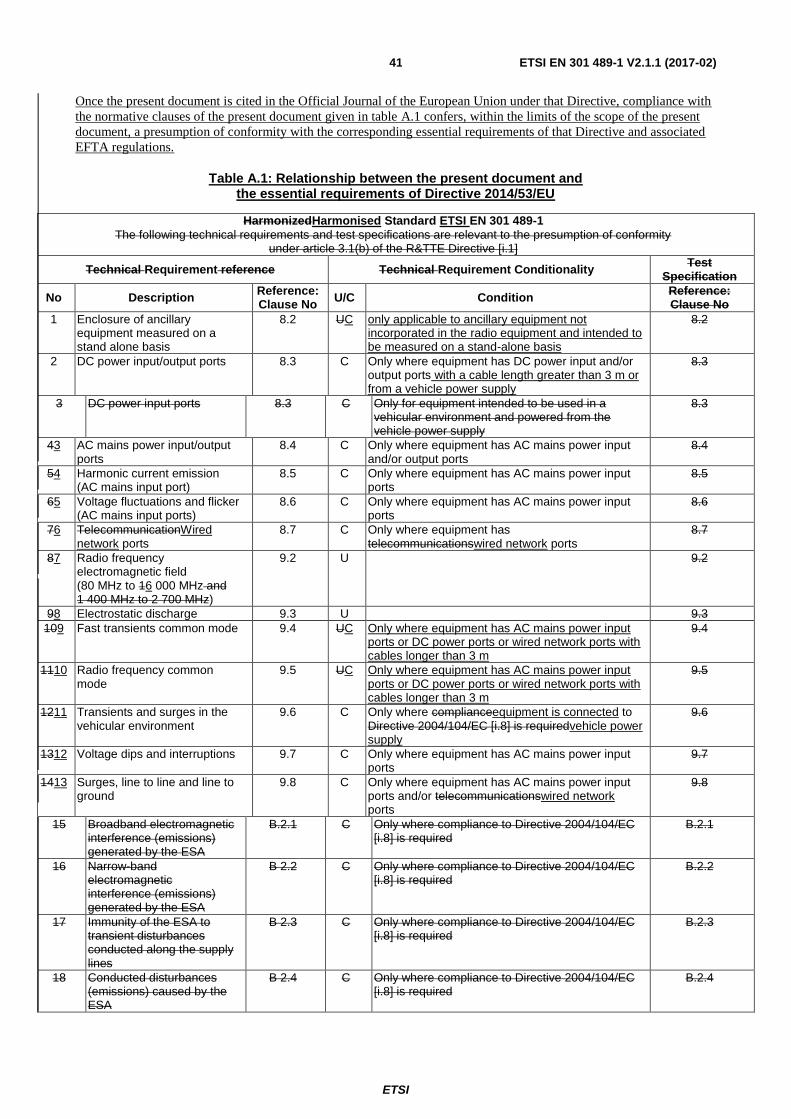
ETSI
ETSI EN 301 489-1 V2.1.1 (2017-02) 41
Once the present document is cited in the Official Journal of the European Union under that Directive, compliance with
the normative clauses of the present document given in table A.1 confers, within the limits of the scope of the present
document, a presumption of conformity with the corresponding essential requirements of that Directive and associated
EFTA regulations.
Table A.1: Relationship between the present document and the essential requirements of Directive 2014/53/EU
HarmonizedHarmonised Standard ETSI EN 301 489-1
The following technical requirements and test specifications are relevant to the presumption of conformity under article 3.1(b) of the R&TTE Directive [i.1]
Technical Requirement reference Technical Requirement Conditionality Test
Specification
No Description Reference: Clause No
U/C Condition Reference: Clause No
1 Enclosure of ancillary equipment measured on a stand alone basis
8.2 UC only applicable to ancillary equipment not incorporated in the radio equipment and intended to be measured on a stand-alone basis
8.2
2 DC power input/output ports 8.3 C Only where equipment has DC power input and/or output ports with a cable length greater than 3 m or from a vehicle power supply
8.3
3 DC power input ports 8.3 C Only for equipment intended to be used in a vehicular environment and powered from the vehicle power supply
8.3
43 AC mains power input/output ports
8.4 C Only where equipment has AC mains power input and/or output ports
8.4
54 Harmonic current emission (AC mains input port)
8.5 C Only where equipment has AC mains power input ports
8.5
65 Voltage fluctuations and flicker (AC mains input ports)
8.6 C Only where equipment has AC mains power input ports
8.6
76 TelecommunicationWired network ports
8.7 C Only where equipment has telecommunicationswired network ports
8.7
87 Radio frequency electromagnetic field (80 MHz to 16 000 MHz and 1 400 MHz to 2 700 MHz)
9.2 U 9.2
98 Electrostatic discharge 9.3 U 9.3
109 Fast transients common mode 9.4 UC Only where equipment has AC mains power input ports or DC power ports or wired network ports with cables longer than 3 m
9.4
1110 Radio frequency common mode
9.5 UC Only where equipment has AC mains power input ports or DC power ports or wired network ports with cables longer than 3 m
9.5
1211 Transients and surges in the vehicular environment
9.6 C Only where complianceequipment is connected to Directive 2004/104/EC [i.8] is requiredvehicle power supply
9.6
1312 Voltage dips and interruptions 9.7 C Only where equipment has AC mains power input ports
9.7
1413 Surges, line to line and line to ground
9.8 C Only where equipment has AC mains power input ports and/or telecommunicationswired network ports
9.8
15 Broadband electromagnetic interference (emissions) generated by the ESA
B.2.1 C Only where compliance to Directive 2004/104/EC [i.8] is required
B.2.1
16 Narrow-band electromagnetic interference (emissions) generated by the ESA
B 2.2 C Only where compliance to Directive 2004/104/EC [i.8] is required
B.2.2
17 Immunity of the ESA to transient disturbances conducted along the supply lines
B 2.3 C Only where compliance to Directive 2004/104/EC [i.8] is required
B.2.3
18 Conducted disturbances (emissions) caused by the ESA
B 2.4 C Only where compliance to Directive 2004/104/EC [i.8] is required
B.2.4
ETSI
ETSI EN 301 489-1 V2.1.1 (2017-02) 42
Key to columns:
Requirement:
No A unique identifier for one row of the table which may be used to identify a requirement or its test
specification.
Description A textual reference to the requirement.
Clause Number Identification of clause(s) defining the requirement in the present document unless another
document is referenced explicitly.
Requirement Conditionality:
U/C Indicates whether the requirement is unconditionally applicable (U) or is conditional upon the
manufacturer's claimed functionality of the equipment (C).
Condition Explains the conditions when the requirement is or is not applicable for a requirement which is
classified "conditional".
Presumption of conformity stays valid only as long as a reference to the present document is maintained in the list
published in the Official Journal of the European Union. Users of the present document should consult frequently the
latest list published in the Official Journal of the European Union.
Other Union legislation may be applicable to the product(s) falling within the scope of the present document.
A.2 Relationship between the present document and the essential requirements of Directive 2014/30/EU
The present document has been prepared to provide one voluntary means of conforming to the essential requirements of
Directive 2014/30/EU [i.2] of the European Parliament and of the Council of 26 February 2014 on the harmonisation of
the laws of the Member States relating to electromagnetic compatibility (recast).
NOTE: The corresponding Commission's standardisation request to provide one voluntary means of conforming
to the essential requirements Directive 2014/30/EU on the harmonisation of the laws of the Member
States relating to electromagnetic compatibility (recast) [i.2] is expected shortly.
Once the present document is cited in the Official Journal of the European Union under that Directive, compliance with
the normative clauses of the present document given in table A.2 confers, within the limits of the scope of the present
document, a presumption of conformity with the corresponding essential requirements of that Directive, and associated
EFTA regulations.
ETSI
ETSI EN 301 489-1 V2.1.1 (2017-02) 43
Table A.2: Relationship between the present document and the essential requirements of Directive 2014/30/EU
Harmonised Standard ETSI EN 301 489-1
Requirement Requirement Conditionality
No Description Reference: Clause No
U/C Condition
1 Enclosure of ancillary equipment measured on a stand alone basis
8.2 U
2 DC power input/output ports 8.3 C Only where equipment has DC power input and/or output ports with a cable length greater than 3 m or from a vehicle power supply
3 AC mains power input/output ports
8.4 C Only where equipment has AC mains power input and/or output ports
4 Harmonic current emission (AC mains input port)
8.5 C Only where equipment has AC mains power input ports
5 Voltage fluctuations and flicker (AC mains input ports)
8.6 C Only where equipment has AC mains power input ports
6 Wired network ports 8.7 C Only where equipment has wired network ports
7 Radio frequency electromagnetic field (80 MHz to 6 000 MHz)
9.2 U
8 Electrostatic discharge 9.3 U
9 Fast transients common mode 9.4 C Only where equipment has AC mains power input ports or DC power ports or wired network ports with cables longer than 3 m
10 Radio frequency common mode
9.5 C Only where equipment has AC mains power input ports or DC power ports or wired network ports with cables longer than 3 m
11 Transients and surges in the vehicular environment
9.6 C Only where equipment is connected to vehicle power supply
12 Voltage dips and interruptions 9.7 C Only where equipment has AC mains power input ports
13 Surges, line to line and line to ground
9.8 C Only where equipment has AC mains power input ports and/or wired network ports
Key to columns:
Requirement:
No A unique identifier for one row of the table which may be used to identify a requirement.
Description A textual reference to the requirement.
Clause Number Identification of clause(s) defining the requirement in the present document unless another
document is referenced explicitly.
Requirement Conditionality:
U/C Indicates whether the requirement is to be unconditionally applicable (U) or is conditional upon
the manufacturersmanufacturer's claimed functionality of the equipment (C).
Condition Explains the conditions when the requirement shallis or shallis not be applicable for a technical
requirement which is classified "conditional".
Test Specification:
E/O Indicates whether the test specification forms part of the Essential Radio Test Suite (E) or
whether it is one of the Other Test Suite (O).

ETSI
ETSI EN 301 489-1 V2.1.1 (2017-02) 44
NOTE: All tests whether "E" or "O" are relevant to the requirements. Rows designated "E" collectively make up
the Essential Radio Test Suite; those designated "O" make up the Other Test Suite; for those designated
"X" there is no test specified corresponding to the requirement. The completion of all tests classified "E"
as specified with satisfactory outcomes is a necessary condition for a presumption of conformity.
Compliance with requirements associated with tests classified "O" or "X" is a necessary condition for
presumption of conformity, although conformance with the requirement may be claimed by an equivalent
test or by manufacturer's assertion supported by appropriate entries in the technical construction file.
Clause Number Identification of clause(s) defining the test specification in the present document unless
another document is referenced explicitly Where no test is specified (that is, where the
previous field is "X") this field remains blank.
ETSI
ETSI EN 301 489-1 V2.1.1 (2017-02) 45
Annex B (normative): Technical requirements for after market equipment (ESAs), which are not related to immunity related functions of the vehicle, necessary to demonstrate conformance to the motor vehicle EMC Directive 2004/104/EC
B.1 General
The annex numbers and clause numbers used are taken directly from Directive 2004/104/EC [i.8].
When reference is made to a clause number in the present document, this will be followed by the term "present
document". The requirements of the tests set out below are in summary form, for full details, the
Directive 2004/104/EC [i.8] and the reference documents quoted shall be used.
B.2 Technical requirements for radio equipment
B.2.1 Broadband electromagnetic interference (emissions) generated by the ESA
The provisions for broadband electromagnetic interferences are found in annex I, clause 6.5. The method of
measurement is described in annex VII.
The tests shall normally be performed according to CISPR 25 [10], clause 6 in an Absorber Lined Shielded Enclosure
(ALSE). As an alternative an Open Area Test Site (OATS), which complies with the requirements of
EN 55016-1-4 [i.9] may be used.
The ESA shall be tested in normal operation mode.
The limit values are set out in annex I, clause 6.5.2.1.
The test applies to broadband emissions of ESAs that are defined as follows, quote:
"2.1.5. "Broadband emission" means an emission, which has a bandwidth greater than that of a particular
measuring apparatus or receiver (International Special Committee on Radio Interference (CISPR) 25, 2nd
edition)."
unquote.
Radio equipment and many types of its associated ancillary equipment do not generate broadband emission in the
meaning of this definition 2.1.5 in annex I of Directive 2004/104/EC [i.8]. There is no need to perform the test set out
above.
B.2.2 Narrow-band electromagnetic interference (emissions) generated by the ESA
The provisions for narrow-band electromagnetic interferences are found in annex I, clause 6.6. The method of
measurement is described in annex VIII.
The tests shall normally be performed according to CISPR 25 [10], clause 6 in an Absorber Lined Shielded Enclosure
(ALSE). As an alternative an Open Area Test Site (OATS), which complies with the requirements of
EN 55016-1-4 [i.9] may be used.
ETSI
ETSI EN 301 489-1 V2.1.1 (2017-02) 46
The ESA shall be tested in normal operation mode.
The limit values are set out in annex I, clause 6.6.2.1.
The test applies to narrow-band emissions of ESAs that are defined as follows, quote:
"2.1.6. "Narrowband emission" means an emission which has a bandwidth less than that of a particular
measuring apparatus or receiver (CISPR 25 [10])."
unquote.
Radio equipment and its associated ancillary equipment may generate narrow-band emission (spurious emission) in the
meaning of this definition 2.1.6 in annex I of Directive 2004/104/EC [i.8].
B.2.2.1 Narrow-band spurious emissions of RF transmitters
For RF transmitters, it is not necessary to perform this test if the provisions of annex I, clause 8.7 are met. This clause
reads as follows, quote:
"RF transmitters shall be tested in the transmit mode. Wanted emissions (e.g. from RF transmitting systems)
within the necessary bandwidth and out of band emissions are disregarded for the purpose of this Directive.
Spurious emissions are subject to this Directive, but need not be tested if the transmitter has a Declaration of
Conformity according to Directive 1999/5/EC [i.1] using a harmonized standard."
unquote.
The harmonized standards which contain the above requirements are those published in the Official Journal of the
European Union, under the Directive 1999/5/EC [i.1], and are used to demonstrate conformity to article 3.2 of this
Directive.
B.2.2.2 Narrow-band spurious emissions of transceivers in stand by mode and receivers
It is not necessary to perform this test if the requirements set out in the harmonized radio standards of ETSI used to
demonstrate conformity to article 3.2 of the R&TTE Directive [i.1] are met.
B.2.2.3 Narrow-band spurious emissions of ancillary equipment
For ancillary equipment tested on a stand alone basis according to clause 8.2 of the present document, the provisions of
annex I, clause 6.6 are deemed to be fulfilled.
B.2.3 Immunity of the ESA to transient disturbances conducted along the supply lines
The provisions for the immunity of ESAs to transient disturbances conducted along the supply lines are found in
annex I, clause 6.8. The test method is described in annex X.
The test is performed according to ISO 7637-2 [8], applying the test pulses 1, 2a, 2b, 3a, 3b, and 4 to the supply lines as
well as to other connections of ESAs which may be operationally connected to supply lines.
Radio equipment and its associated ancillary equipment may be affected by such transient disturbances. Immunity tests
are found in clause 9.6 of the present document.
B.2.4 Conducted disturbances (emissions) caused by the ESA
The provisions for conducted disturbances from ESAs are found in annex I, clause 6.9. The test method is described in
annex X.
The measurement is performed according to ISO 7637-2 [8] on the supply lines as well as other connections of the
ESAs which may be operationally connected to supply lines.

ETSI
ETSI EN 301 489-1 V2.1.1 (2017-02) 47
For radio and its associated ancillary equipment, it is not necessary to perform this test if the provisions of annex I,
clause 8.5 are met. This clause reads as follows, quote:
"8.5. Conducted emission
ESAs that are not switched, contain no switches or do not include inductive loads need not be tested for
conducted emission and shall be deemed to comply with paragraph 6.9 of annex I."
unquote.

ETSI
ETSI EN 301 489-1 V2.1.1 (2017-02) 48
Annex C (normative):
Presumption of conformity stays valid only as long as a reference to the present document is maintained in the list
published in the Official Journal of the European Union. Users of the present document should consult frequently the
latest list published in the Official Journal of the European Union.
Other Union legislation may be applicable to the product(s) falling within the scope of the present document.
ETSI
ETSI EN 301 489-1 V2.1.1 (2017-02) 49
Annex B (normative): Application of harmonizedharmonised EMC standards to multi--radio, and multi--standard-radio, and combined radio, non-radio equipment
This annex details the application of harmonized EMC standards to combined products, which include a radio and/or a
telecommunication function. Examples to be covered include products containing multiple radio technologies, radio in
IT equipment, radio in domestic equipment, etc.
This annex covers combined products, which are subject to the provisions of the R&TTE Directive [i.1] as a result of
this combination.
The purpose of this annex is:
to provide guidance with the testing of this type of equipment;
to eliminate duplicate testing wherever possible;
to recommend the selection of appropriate performance assessment and performance criteria for this type of
equipment;
This annex does not apply to:
single custom built products that are tailored to a specific customer quotation;
products that operate independently if they are not contained within a single enclosure.
C.1 Where all products can operate independently of each other
In this category it is assumed that the individual products will have been assessed and shown to be in compliance with
the relevant directives.
The combined equipment shall comply with article 3.1(b) of the R&TTE Directive [i.1].
Individual products used within the combined equipment have complete functionality in their own right. If used on their
own then the relevant harmonized EMC standard for that product should be used to demonstrate conformity for that
product.
Evaluation of combined equipment may be made by reviewing the existing assessments of the individual products. If an
individual product is used according to its manufacturers' instructions, and it has been previously assessed in a
configuration which is representative of the combined equipment usage, it is not necessary to re-assess that product or
the combined equipment. Additional assessment of the combined equipment should only be made where there is
insufficient information to make an evaluation, or where the results of the evaluation are unclear.
C.1.1 Emissions
It is recognized that the individual products which make up the combined equipment may have been assessed to
different harmonized EMC standards with differing emission limits. However, for combined equipment, the limits used
to demonstrate compliance shall be taken from the harmonized EMC standard for the primary product (declared by the
manufacturer). Ports not covered in the harmonized EMC standard relevant to the primary product shall be assessed
against the details set out for these ports in the harmonized EMC standards for the other products contained within the
combined equipment.
Where one or more of the products is a radio the exclusion band details shall be taken from the harmonized radio
product EMC standard and taken into account and applied during the EMC assessment of the combined equipment.
ETSI
ETSI EN 301 489-1 V2.1.1 (2017-02) 50
Where the emissions from the combined equipment are identified as spurious emissions, as defined in ITU-R Radio
Regulations article no 1.145 [i.10], from any radio product incorporated into the combined equipment, these emissions
shall be regarded as radio spurious emissions subject to article 3.2 of the R&TTE Directive [i.1]. The assessment of
these spurious emissions can be found in the harmonized radio standard for use under article 3.2 of the R&TTE
Directive [i.1].
C.1.2 Immunity
It is recognized that the individual products which make up the combined equipment may have been assessed to
different harmonized EMC standards with differing immunity test levels, phenomena and performance criteria.
However, for combined equipment, the harmonized EMC standard for the primary product (declared by the
manufacturer) shall be used.
The following additional immunity tests shall be applied to the combined equipment if not already included in the
assessment of the primary product:
conducted immunity on telecommunications, signal and control ports as defined in the harmonized EMC
standards for the other products contained within the combined equipment;
radiated immunity (Radio Frequency electromagnetic field) as defined in the harmonized EMC standards for
the radio and/or telecommunication functions contained within the combined equipment.
Where one or more of the products is a radio the exclusion band details shall be taken from the harmonized radio
product EMC standard and be taken into account and applied during the EMC assessment of the combined equipment.
If additional immunity tests have been performed then the relevant performance criteria shall be taken from the
harmonized EMC product standard containing these tests.
Where the combined equipment relies on one or more communications links for its operation, then these links shall be
maintained during immunity testing in accordance with the relevant harmonized EMC product standard, and any
degradation of performance shall be in accordance with the manufacturers' declaration.
For a combined equipment containing a radio, loss of link or degradation of performance shall not be considered as a
non-compliance if this is due to a narrow band receiver response as defined in the relevant radio EMC product
harmonized standard. For combined equipment containing radio products the performance criteria shall include that the
transmitter is not unintentionally operated during testing. The actual performance criteria used shall be recorded in any
subsequent test report.
C.2 Where one or more of the individual products cannot operate independently
Within this category of combined equipment, the product providing the control functions can be operated separately and
therefore will have been assessed to the relevant harmonized EMC standard for that product.
The combined equipment shall comply with article 3.1(b) of the R&TTE Directive [i.1].
C.2.1 Products physically incorporated within another product
When a combined equipment is made up from the incorporation of one or more products into another product, then the
assessment of the combined equipment shall be on the same basis as that recommended in clauses C.1.1 and C.1.2.
ETSI
ETSI EN 301 489-1 V2.1.1 (2017-02) 51
C.2.2 Products connected to, but not physically incorporated within, another product
When a combined equipment is made up from one or more products connected to, but not physically incorporated into
another product, then the EMC assessment may be carried out using one of the following options:
where the testing of the combined equipment may be performed on a complete configuration which is
representative of typical configuration, then the assessment shall be on the same basis as that recommended in
clauses C.1.1 and C.1.2;
where the physical and/or cable distance between the various parts of the combined equipment is such that
testing of the combination would not be representative of a typical configuration, then each part of the
combined equipment may be evaluated individually to the relevant harmonized EMC standard. Details of
typical configurations shall be declared by the manufacturer.
Care should be taken during testing to provide adequate control of the individual parts in order to maintain
representative operation.
C.3 Where none of the component parts operate independently
This category of combined equipment is characterized by the fact that the various component parts cannot operate
independently.
The combined equipment shall comply with article 3.1(b) of the R&TTE Directive [i.1].
The primary function of the combined equipment shall be declared by the manufacturer.
C.3.1 Emissions
The limits and tests used to demonstrate compliance of the combined equipment shall be taken from the harmonized
EMC standard relevant to the primary function (declared by the manufacturer). Ports not covered in the harmonized
EMC standard relevant to the primary function shall be assessed against the details set out for these ports in the
harmonized EMC standards for the other products/functions contained within the combined equipment.
Where one or more of the functions is a radio the exclusion band details shall be taken from the relevant harmonized
radio product EMC standard and applied during the EMC assessment of the combined equipment.
Where the emissions from the combined equipment are identified as spurious emissions, as defined in ITU-R Radio
Regulations article no 1.145 [i.10], from any radio product incorporated into the combined equipment (except Broadcast
receivers) these emissions shall be regarded as radio spurious emissions subject to article 3.2 of the R&TTE
Directive [i.1]. The assessment of these spurious emissions can be found in the harmonized radio standard for use under
article 3.2 of the R&TTE Directive [i.1].
C.3.2 Immunity
The test levels, performance criteria and test methods used to demonstrate compliance of the combined equipment shall
be taken from the harmonized EMC standard for the primary function (declared by the manufacturer).
The following additional immunity tests shall be applied to combined equipment if not already included in the
assessment of the primary function:
radiated immunity (Radio Frequency electromagnetic field) as defined in the harmonized EMC standards for
the radio and/or telecommunication functions contained within the combined equipment;
conducted immunity on telecommunications signal and control ports as defined in the harmonized EMC
standards for the radio and/or telecommunication functions contained within the combined equipment.
ETSI
ETSI EN 301 489-1 V2.1.1 (2017-02) 52
If additional immunity tests have been performed then the relevant performance criteria shall be taken from the
harmonized EMC product standard containing these tests.
Where one or more of the functions is a radio, the exclusion band details shall be taken from the relevant harmonized
radio product EMC standard and applied during the EMC assessment of the combined equipment.
Where the combined equipment relies on one or more communications links for its operation, then these links shall be
maintained during immunity testing in accordance with the relevant harmonized EMC standards, and any degradation
of performance shall be in accordance with the manufacturers' declaration.
For a combined equipment containing a radio, loss of link or degradation of performance shall not be considered as a
non-compliance if this is due to a narrow band receiver response as defined in the relevant radio EMC product
harmonized standard. For combined equipment containing radio product/function the performance criteria shall include
that the transmitter is not unintentionally operated during testing. The actual performance criteria used shall be recorded
in any subsequent test report.
C.4 Application of harmonized EMC standards to multi-radio and multi-standard-radio equipment
B.1 Introduction
This clause details the additional considerations when dealing with multi-radio and multi-standard-radio equipment.
These shall take precedence in case of conflict with those determined in clauses C.1, C.2 and C.3.
For Multi-radio and multi-standard-radio equipment, the applicable EMC phenomena and limits are those set out in the
ETSI EN 301 489 series [i.13i.13].
The test conditions, performance assessment and performance criteria as stated in the present document are used
together with the specific product relatedrelevant radio technology parts of the ETSI EN 301 489 series [i.13i.13].
C.4.1B.2 Multi-radio equipment capable of independent transmission
If the individual radio products and their corresponding radio links operate independently in normal usage (as declared
by the manufacturer), then separate testing may be used. In this case the individual radio products shall be assessed to
the appropriate harmonizedharmonised EMC product standards.
C.4.2B.3 Multi-radio equipment and multi-standard-radio equipment not capable of independent transmission
However, where operation of the individual radio products and their corresponding radio links is simultaneous in
normal usage (as declared by the manufacturer), then separate testing shall not be used. In this case testing shall be
performed on the complete combined equipment. An overall performance criteria is required for the combined
equipment. This may be developed by examining the individual performance criteria of the various radio products
involved. The performance criteria used shall be declared by the manufacturer and recorded in the test report.
Where multiple operational frequencies are used, exclusion bands shall be defined for each of the radio products and all
of these shall be used during testing.
ETSI
ETSI EN 301 489-1 V2.1.1 (2017-02) 53
CB.4.3 Multi-radio equipment comprising of numerous identical radio transmitters
Typically this situation exists where a baseband amplifier is used to feed multiple radio front ends that may be located
in a different location to the baseband amplifier. In this situation and in a manner similar to that described in
clause C.2.2 the individual parts may be tested separately to the appropriate harmonised EMC standard applicable to
that product part.

ETSI
ETSI EN 301 489-1 V2.1.1 (2017-02) 54
Annex D (informative): The EN title in the official languages
The enlargement of the European Union (EU) resulted in a requirement from the EU for a larger number of languages
for the translation of the titles of Harmonized Standards and mandated ENs that are to be listed in the Official Journal to
support the implementation of this legislation.
For this reason the title translation concerning the present document can be consulted via the e-approval application.

ETSI
ETSI EN 301 489-1 V2.1.1 (2017-02) 55
Annex E

ETSI
ETSI EN 301 489-1 V2.1.1 (2017-02) 56
Annex C (informative): Bibliography
ETSI TR 102 070-1 (V1.2.1):EG 203 336: "Electromagnetic compatibility and Radio spectrum Matters (ERM); Guide
to the application of harmonized standards to multi-for the selection of technical parameters for the production of
Harmonised Standards covering article 3.1(b) and article 3.2 of Directive 2014/53/EU".
CENELEC EN 55016-1-4 (2010) + A1 (2012): "Specification for radio disturbance and combined radioimmunity
measuring apparatus and non-radiomethods - Part 1-4: Radio disturbance and immunity measuring apparatus -
Ancillary equipment; Part 1: ElectroMagnetic Compatibility - Radiated disturbances".
ETSI
ETSI EN 301 489-1 V2.1.1 (2017-02) 57
Annex D (informative): Change history
Version Information about changes
2.1.1
Compared with earlier versions that were cited under previous EU Directives, the following changes have been introduced:
Radiated immunity testing to a continuous sweep between 80 MHz and 6 000 MHz at 3V/m, as opposed to the previous frequency range of 80 MHz to 1 000 MHz and 1 400 MHz to 2 700 MHz in earlier editions of the ETSI EN 301 489 series [i.13].
New derivations of exclusion bands more closely linked to the operational characteristics of the radio link(s) in the EUT. In many cases this has resulted in new exclusion bands in the individual parts of the ETSI EN 301 489 series [i.13].
Surge test method aligned with CENELEC EN 61000-4-5 [5].
Also with this version the previous annex B that dealt with aftermarket fitment of radio equipment into vehicles has been removed following the demise of the EU motor vehicle EMC Directive.
Those parts of annex C that covered combined equipment have been removed.
The above changes impact all other parts of the ETSI EN 301 489 series [i.13].
More information regarding the changes between the different versions of the ETSI EN 301 489 series [i.13] may be found in ETSI TR 103 088 [i.9].
ETSI
ETSI EN 301 489-1 V2.1.1 (2017-02) 58
History
Document history
V1.2.1 August 2000 Publication
V1.3.1 September 2001 Publication
V1.4.1 August 2002 Publication
V1.5.1 November 2004 Publication
V1.6.1 September 2005 Publication
V1.8.1 April 2008 Publication
V1.9.1 April 2011 One-step Approval Procedure OAP 20110816: 2011-04-18 to 2011-08-16
V1.9.2 September 2011 Publication
V2.1.0 April 2016 EN Approval Procedure AP 20160705: 2016-04-06 to 2016-07-05
V2.1.1 November 2016 Vote V 20170122: 2016-11-23 to 2017-01-23
V2.1.1 February 2017 Publication


![Draft ETSI EN 301 489-9 V2.1...2000/02/01 · ETSI 6 Draft ETSI EN 301 489-9 V2.1.0 (2016-09) 1 Scope The present document, together with ETSI EN 301 489-1 [1], covers the assessment](https://img.pdfslide.us/doc/110x75/606a6768dee68d6bb84c1cb0/draft-etsi-en-301-489-9-v21-20000201-etsi-6-draft-etsi-en-301-489-9-v210.jpg)