Embed Size (px)
Citation preview

Final draft ETSI EG 202 106 V1.1.8 (2002-04)ETSI Guide
Methods for Testing and Specification (MTS);Guidelines for the use of SDL as a descriptive tool

ETSI
ReferenceREG/MTS-00072
KeywordsSDL, MSC, ASN.1, UML, methodology
ETSI
650 Route des LuciolesF-06921 Sophia Antipolis Cedex - FRANCE
Tel.: +33 4 92 94 42 00 Fax: +33 4 93 65 47 16
Siret N° 348 623 562 00017 - NAF 742 CAssociation à but non lucratif enregistrée à laSous-Préfecture de Grasse (06) N° 7803/88
Important notice
Individual copies of the present document can be downloaded from:http://www.etsi.org
The present document may be made available in more than one electronic version or in print. In any case of existing or perceived difference in contents between such versions, the reference version is the Portable Document Format (PDF).
In case of dispute, the reference shall be the printing on ETSI printers of the PDF version kept on a specific network drive within ETSI Secretariat.
Users of the present document should be aware that the document may be subject to revision or change of status. Information on the current status of this and other ETSI documents is available at
http://portal.etsi.org/tb/status/status.asp
If you find errors in the present document, send your comment to:[email protected]
Copyright Notification
Reproduction is only permitted for the purpose of standardization work undertaken within ETSI.The copyright and the foregoing restrictions extend to reproduction in all media.
© European Telecommunications Standards Institute 2002.All rights reserved.
DECTTM, PLUGTESTSTM and UMTSTM are Trade Marks of ETSI registered for the benefit of its Members.TIPHONTM and the TIPHON logo are Trade Marks currently being registered by ETSI for the benefit of its Members. 3GPPTM is a Trade Mark of ETSI registered for the benefit of its Members and of the 3GPP Organizational Partners.
Final draft ETSI EG 202 106 V1.1.8 (2002-04)2
Contents
Intellectual Property Rights.........................................................................................................................6
Foreword.....................................................................................................................................................6
1 Scope.................................................................................................................................................7
2 References.........................................................................................................................................7
3 Definitions and abbreviations...........................................................................................................83.1 Definitions...................................................................................................................................................83.2 Abbreviations..............................................................................................................................................8
4 Introduction.......................................................................................................................................8
5 Using specification languages in protocol standards......................................................................105.1 Introduction...............................................................................................................................................105.2 Layered protocols......................................................................................................................................105.3 Developing a protocol specification..........................................................................................................105.3.1 Specifying requirements......................................................................................................................105.3.2 Developing a logical model.................................................................................................................105.3.3 Developing a physical model..............................................................................................................11
6 Naming Conventions.......................................................................................................................146.1 General......................................................................................................................................................146.1.1 Case sensitivity....................................................................................................................................156.1.2 Length of names..................................................................................................................................166.1.3 Reserved words...................................................................................................................................166.2 SDL and MSC...........................................................................................................................................166.2.1 Use of non-significant characters........................................................................................................166.2.2 Multiple use of names.........................................................................................................................176.2.3 Making names meaningful..................................................................................................................176.2.3.1 Block, process and instance names................................................................................................186.2.3.2 Procedure, operator and method names.........................................................................................186.2.3.3 Signal names..................................................................................................................................186.2.3.4 Signal List and interface names.....................................................................................................186.2.3.5 SDL State names............................................................................................................................196.2.3.6 Names of Variables and Constants................................................................................................196.2.3.7 Timers............................................................................................................................................206.3 Data types..................................................................................................................................................20
7 Presentation and layout of diagrams...............................................................................................207.1 The general flow of behaviour across a page............................................................................................217.2 Behaviour covering more than one page...................................................................................................227.2.1 SDL behaviour diagrams.....................................................................................................................227.2.2 Definitions in behaviour diagrams......................................................................................................267.2.3 UML activity diagrams........................................................................................................................277.3 Text extension symbols.............................................................................................................................277.4 Alignment and orientation of symbols......................................................................................................287.4.1 Alignment............................................................................................................................................287.4.2 Orientation...........................................................................................................................................307.5 Structuring behaviour descriptions...........................................................................................................307.5.1 Basic structuring principles.................................................................................................................307.5.2 Structuring using procedures and operations......................................................................................317.5.3 Emphasizing the difference between normal and exceptional behaviour flows.................................31
8 Using procedures, operations and macros.......................................................................................338.1 Procedures.................................................................................................................................................338.1.1 Using procedures to replace informal tasks.........................................................................................358.1.2 Procedure signature (parameters and returned values)........................................................................368.1.3 Procedure body....................................................................................................................................38
ETSI
Final draft ETSI EG 202 106 V1.1.8 (2002-04)3
8.1.4 Avoiding side-effects...........................................................................................................................408.1.5 Naming of procedures.........................................................................................................................418.2 Operations.................................................................................................................................................428.3 Using macros.............................................................................................................................................46
9 Using decisions...............................................................................................................................479.1 Decisions...................................................................................................................................................489.1.1 Naming of identifiers used with decisions..........................................................................................489.1.2 Using decisions to structure a specification........................................................................................489.1.3 Use of text strings in decisions............................................................................................................489.1.4 Use of enumerated types in decisions.................................................................................................499.1.4.1 Use of ELSE..................................................................................................................................509.1.5 Using SYNTYPES to limit the range of values in decisions..............................................................509.1.6 Use of symbolic names in decision outcomes.....................................................................................519.1.7 Use of range expressions in decisions.................................................................................................519.1.8 Use of Procedures in Decisions...........................................................................................................529.1.9 Use of ANY in decisions.....................................................................................................................549.2 Use of options rather than decisions.........................................................................................................549.3 Flow control statements............................................................................................................................55
10 System structure, communication and addressing..........................................................................5710.1 System structure........................................................................................................................................5710.2 Minimizing the SDL model......................................................................................................................5810.3 Avoiding repetition by using SDL types...................................................................................................5910.3.1 Defining the same behaviour at both ends of a protocol.....................................................................6010.3.2 Static instances to represent repeated functionality.............................................................................6010.4 Interfaces...................................................................................................................................................6110.5 Diagrams showing relationships...............................................................................................................6210.5.1 Use of associations between class symbols.........................................................................................6310.5.2 Use of a class symbol for an INTERFACE definition........................................................................6410.6 Structure diagrams using interfaces between agents.................................................................................6410.7 Communication and Addressing...............................................................................................................6510.7.1 Use of INTERFACE and SIGNALLIST definitions...........................................................................6510.7.2 Indicating the use of signals in inputs and outputs..............................................................................6610.7.3 Directing messages to the right process..............................................................................................6610.7.4 Differentiating messages.....................................................................................................................6710.7.5 Multiple outputs...................................................................................................................................6810.7.6 Transitions triggered by a set of signals..............................................................................................6810.8 Gates and implicit channels......................................................................................................................6810.9 Other structuring mechanisms...................................................................................................................6910.9.1 Processes within a process...................................................................................................................6910.9.2 Shared data..........................................................................................................................................6910.9.3 Hiding and re-using parts of a state.....................................................................................................7010.9.4 Using packages....................................................................................................................................7110.9.5 Exception handling..............................................................................................................................71
11 Specification and use of data..........................................................................................................7211.1 Specifying messages.................................................................................................................................7211.1.1 Structuring messages...........................................................................................................................7311.1.2 Ordering message parameters..............................................................................................................7411.1.3 Transposing other message formats....................................................................................................7511.2 Specifying data that is internal to the SDL model....................................................................................7511.2.1 Use of symbolic names........................................................................................................................7511.2.2 Using data TYPE and SYNTYPE.......................................................................................................7611.2.3 Using OBJECT TYPE.........................................................................................................................77
12 Using Message Sequence Charts (MSC)........................................................................................7712.1 Introduction...............................................................................................................................................7712.2 Relationship between MSC and SDL.......................................................................................................7712.3 Presentation and layout.............................................................................................................................7712.3.1 Annotations..........................................................................................................................................7812.4 Naming and scope.....................................................................................................................................7912.5 MSC document..........................................................................................................................................79
ETSI
Final draft ETSI EG 202 106 V1.1.8 (2002-04)4

12.6 Structuring.................................................................................................................................................7912.6.1 Architecture.........................................................................................................................................8012.6.1.1 Instance..........................................................................................................................................8012.6.1.2 Instance decomposition..................................................................................................................8012.6.1.3 Dynamic instances.........................................................................................................................8012.6.1.4 Environment...................................................................................................................................8112.6.2 Behaviour............................................................................................................................................8212.6.2.1 High-level MSC (HMSC)..............................................................................................................8212.6.2.2 MSC reference in basic MSC........................................................................................................8412.6.2.3 Inline expression............................................................................................................................8512.7 Data...........................................................................................................................................................8612.8 Message.....................................................................................................................................................8612.8.1 Incomplete messages...........................................................................................................................8812.9 Condition...................................................................................................................................................8912.10 Action........................................................................................................................................................9012.11 Timer.........................................................................................................................................................9012.12 Control Flow.............................................................................................................................................9212.13 Time..........................................................................................................................................................9212.14 General ordering and coregion..................................................................................................................9312.15 Relationship between MSC and UML Sequence Diagrams.....................................................................94
Annex A (informative): Reserved words.......................................................................................96
A.1 SDL.................................................................................................................................................96A.1.1 Keywords..................................................................................................................................................96A.1.2 Predefined words.......................................................................................................................................97
A.2 MSC................................................................................................................................................97
A.3 ASN.1..............................................................................................................................................98
A.4 UML................................................................................................................................................98
Annex B (informative): Summary of guidelines...........................................................................99
History.....................................................................................................................................................103
ETSI
Final draft ETSI EG 202 106 V1.1.8 (2002-04)5

Intellectual Property RightsIPRs essential or potentially essential to the present document may have been declared to ETSI. The information pertaining to these essential IPRs, if any, is publicly available for ETSI members and non-members, and can be found in ETSI SR 000 314: "Intellectual Property Rights (IPRs); Essential, or potentially Essential, IPRs notified to ETSI in respect of ETSI standards", which is available from the ETSI Secretariat. Latest updates are available on the ETSI Web server (http://webapp.etsi.org/IPR/home.asp).
Pursuant to the ETSI IPR Policy, no investigation, including IPR searches, has been carried out by ETSI. No guarantee can be given as to the existence of other IPRs not referenced in SR 000 314 (or the updates on the ETSI Web server) which are, or may be, or may become, essential to the present document.
ForewordThis ETSI Guide (EG) has been produced by ETSI Technical Committee Methods for Testing and Specification (MTS), and is now submitted for the ETSI standards Membership Approval Procedure.
ETSI
Final draft ETSI EG 202 106 V1.1.8 (2002-04)6

1 ScopeThe present document establishes a set of guidelines for the formal use of Specification and Description Language (SDL) for descriptive, rather than detailed design, purposes. It also provides some guidance on the use of Message Sequence Charts (MSC), Abstract Syntax Notation 1 (ASN.1) and the Unified Modeling Language (UML) when used in conjunction with SDL. The objective of the guidelines is to provide assistance to rapporteurs of protocol standards so that the SDL that appears in ETSI deliverables is formally expressed, easy to read and understand and at a level of detail consistent with other standards. The present document applies to all standards that make use of SDL to specify protocols, services or any other type of behaviour.
Users of the present document are assumed to have a working knowledge of SDL and, where necessary, MSC, ASN.1 and UML. It should not be considered to be a tutorial in any of these notations and should be read in conjunction with EG 201 383 [1], EG 201 015 [2] and EG 201 872 [3].
2 ReferencesThe following documents contain provisions which, through reference in this text, constitute provisions of the present document.
References are either specific (identified by date of publication and/or edition number or version number) or non-specific.
For a specific reference, subsequent revisions do not apply.
For a non-specific reference, the latest version applies.
[1] ETSI EG 201 383 (V1.1): "Methods for Testing and Specification (MTS); Use of SDL in ETSI deliverables; Guidelines for facilitating validation and the development of conformance tests".
[2] ETSI EG 201 015 (V1.2): "Methods for Testing and Specification (MTS); Specification of protocols and services; Validation methodology for standards using Specification and Description Language (SDL); Handbook".
[3] ETSI EG 201 872 (V1.2): "Methods for Testing and Specification (MTS); Methodological approach to the use of object-orientation in the standards making process".
[4] ITU-T Recommendation Z.100: "Specification and description language (SDL) with corrigendum 1".
[5] ITU-T Recommendation Z.105: "SDL combined with ASN.1 (SDL/ASN.1)".
[6] ITU-T Recommendation Z.109: "SDL combined with UML".
[7] ITU-T Recommendation Z.120: "Messages sequence chart with corrigendum 1".
[8] ITU-T Recommendation X.680: "Information technology - Open Systems Interconnection - Abstract Syntax Notation One (ASN.1): Specification of basic notation".
[9] ITU-T Recommendation X.681: "Information technology - Open Systems Interconnection – Abstract Syntax Notation One (ASN.1): Information object specification".
[10] ITU-T Recommendation X.682: : "Information technology - Open Systems Interconnection – Abstract Syntax Notation One (ASN.1): Constraint specification".
[11] ITU-T Recommendation X.683: : "Information technology - Open Systems Interconnection – Abstract Syntax Notation One (ASN.1): Parameterization of ASN.1 specifications".
[12] ITU-T Recommendation X.690: "Information technology – ASN.1 encoding Rules: Specification of Basic Encoding Rules (BER), Canonical Encoding Rules (CER), and Distinguished Encoding Rules (DER)".
ETSI
Final draft ETSI EG 202 106 V1.1.8 (2002-04)7

[13] ITU-T Recommendation X.691: "Information technology – ASN.1 encoding rules: Specification of Packed Encoding Rules (PER)".
[14] ITU-T Recommendation X.692: "Information technology - Open Systems Interconnection – Abstract Syntax Notation One (ASN.1) encoding rules; Specification of Encoding Control Notation (ECN)".
3 Definitions and abbreviations
4 DefinitionsFor the purposes of the present document, the following terms and definitions apply:
data type: set of data values with common characteristics (equivalent to the ITU-T Recommendation Z.100 [4] term sort)
implementation option: statement in a standard that may or may not be supported in an implementation
normative interface: physical or software interface of a product on which requirements are imposed by a standard
polymorphic: the ability of an operation (SDL method or operator) to have its behaviour specified by a descendant object type
validation: process, with associated methods, procedures and tools, by which an evaluation is made that a standard can be fully implemented, conforms to rules for standards, satisfies the purpose expressed in the record of requirements on which the standard is based and that an implementation that conforms to the standard has the functionality expressed in the record of requirements on which the standard is based
validation model: detailed version of a specification, possibly including parts of its environment, that is used to perform formal validation
5 AbbreviationsFor the purposes of the present document, the following abbreviations apply:
ASN.1 Abstract Syntax Notation No. 1HMSC High-level Message Sequence ChartMSC Message Sequence ChartPid Process identitySDL Specification and Description LanguageUML Unified Modeling Language
6 IntroductionThe ITU-T Specification and Description Language (SDL) defined in ITU-T Recommendation Z.100 [4] is a powerful tool for specifying the essential requirements of standardized protocols or services. The level of formality with which the SDL in a standard is expressed can depend on a large number of factors such as the size and complexity of the system to be standardized and the skills and experience of the standards writers. The specification of a protocol or service as a complete formal model enables the validation of the standard before approval and publication. However, well-constructed, formal SDL has a valuable role to play in providing a simple illustration of the process-related aspects of a standardized system.
SDL is most often found in protocol standards with some associated ASN.1 and MSC. Additionally, as the language specifications converge, SDL is also likely to be used in conjunction with UML in standards. It is, therefore, sensible to consider the relationships between all of these languages and notations when offering guidelines on SDL. The present document is concerned primarily with the development of easy-to-read SDL but also provides some guidance on the use of ASN.1, MSC and UML where this overlaps with the use of SDL.
ETSI
Final draft ETSI EG 202 106 V1.1.8 (2002-04)8
NOTE: Although in the strictest sense SDL, MSC and UML are considered to be languages while ASN.1 is a notation, the terms "language" and "notation" are used interchangeably throughout the present document.
In order to gain the maximum benefit from the use of descriptive SDL, it is necessary for a consistent approach to be taken in its specification by all rapporteurs. In the context of the present document, the term "descriptive SDL" can be taken to mean SDL which is:
formally expressed:
-uses only constructs and symbols that are defined in ITU-T Recommendations Z.100 [4] and Z.105 [5];
complete:
-is specified as a full model with System, Block, Process and Procedure diagrams as necessary;
-has a comprehensive data specification using SDL data or, preferably, ASN.1;
-uses "correct" SDL;
-is not necessarily a simulation or validation model;
easy to read and understand:
-uses meaningful names and identifiers;
-the model structure complements the specification;
-has an open layout which requires a minimum of effort to follow;
-the "how" is hidden from the "what";
-complex programming structures are avoided;
-extensive comments annotate the model;
at a level of detail consistent with other standards:
-is not over-engineered;
-is not an implementation model;
-does not constrain implementations to methods and techniques which are beyond the scope of the standard.
By following the set of simple guidelines presented in the present document, it will be possible for the following benefits to be realized:
Comprehension of the specification can be improved;
Ambiguity can be avoided in the translation of the descriptive SDL into a validation model.
Achieving consistency in the presentation and level of detail specified across a wide range of standards is one of the keys to maintaining the perceived quality of ETSI's products.
The guidelines for the use of SDL for descriptive purposes are grouped in the present document according to the following broad classifications:
naming conventions;
presentation and layout of SDL processes;
the use of procedures, operations and macros;
the use of decisions;
system structure, communications and addressing;
the specification and use of data;
ETSI
Final draft ETSI EG 202 106 V1.1.8 (2002-04)9
the use of Message Sequence Charts (MSC) in association with SDL.
Each of the guidelines is highlighted within the document in bold and italic text. They are all collected together in tabular form in Annex B.
7 Using specification languages in protocol standards
8 IntroductionThis clause gives some consideration to the process of standardizing communication protocols so that guidance can be given on where SDL, ASN.1, MSC and UML can be used effectively.
9 Layered protocolsThere are numerous approaches to the design of communications protocols, each of which is valid in the situation that it is used. Probably the most well known and well used is the ISO layered model or a derivative of it where a protocol system is segmented into distinct logical layers with distinct responsibilities.
The communication between peer layers in this logical model never takes place directly but is achieved through the services of the lower layer. However, this peer-level communication is often specified in a standard without consideration of the signaling between layers. The interface between two adjacent layers is usually called the Service Access Point (SAP) although other terms such as user access and network access are also used. Protocol standards will, in most cases, be considerably simpler if they are restricted either to horizontal communication (peer-to-peer) or vertical communication (inter-layer). Mixing the two can lead to a confusing specification which is difficult to understand.
10 Developing a protocol specificationFor many years, protocol standards have been prepared using the three-stage process described in ITU-T Recommendation I.130. Although the detailed practices specified in this document might now be considered to be out of date and its use is not as widespread as it once was, the underlying method upon which it is based is still relevant as good engineering design practice. Simply put, this is:
1. Specify requirements from the user's perspective;
2. Develop a logical model to meet those requirements;
3. Develop a physical specification of the protocol.
11 Specifying requirementsSpecifying a protocol without first evaluating what it is intended to achieve and what constraints are to be applied to it will almost certainly end in a poor specification. These requirements can easily be expressed using free text and some informal diagrams but the use of UML for this purpose (as described in EG 201 872 [3]) means that this information can be checked by automatic tools and used as input to the later stages of specification.
At this stage of the specification, there should be no need to consider the possible physical architecture of any system implementing the protocol. Requirements should be expressed, as far as possible, entirely from the user's perspective (although the "user" may be a terminal or network application acting on behalf of a human user)
12 Developing a logical modelBefore considering the physical specification of a protocol, there are benefits to be gained by specifying a model based on logical blocks so that the flow of information necessary for meeting the specified requirements can be defined without concern for the detailed format that such information should take. The identification of possible normative interfaces between blocks is also simpler without the constraints imposed by a specific physical architecture.
ETSI
Final draft ETSI EG 202 106 V1.1.8 (2002-04)10

The overlap between UML and both SDL2000 and MSC2000 is such that all of these languages are suitable for this level of specification. In fact, it is unlikely that models developed in either UML or SDL2000 with MSCs would be appreciably different.
Once the logical model is complete, it is necessary to specify a physical model upon which "real" implementations of the protocol standard can be based. This model should not, in most cases, be a detailed implementation model but should be constrained to specify the minimum protocol requirements to guarantee inter-working between modules from different suppliers. A good first step towards this physical model is to define a set of legitimate scenarios for the distribution of the logical blocks within a set of physical entities. Textual tables have traditionally been used quite effectively for this purpose but UML deployment diagrams can provide a graphical means of presenting these requirements.
13 Developing a physical modelIf systems implementing a standardized protocol are to inter-work without problems, it is necessary to specify the detailed content and format of signals between physical entities and the temporal relationships that must exist between these signals. For this specification to be complete and accurate, it may be necessary to describe the behaviour of the physical entities which make up the protocol system.
ASN.1 is generally accepted as the notation to be used within protocol standards for the definition of signal data structures. Although it is not a particularly intuitive notation to use, it has the significant benefit that there are a number of standardized sets of rules (for example, Basic Encoding Rules – BER [12], and Packed Encoding Rules - PER [13]) for encoding ASN.1 structures into "concrete" data items with more or less efficiency. In those cases where even PER does not produce a compact enough encoding, Encoding Control Notation (ECN) specified in ITU-T Recommendation X.692 [14] enables users to define and use their own encoding rules in a standardized form. A further benefit of using ASN.1 is that ITU-T Recommendation Z.105 [5] specifies exactly how ASN.1 is used in conjunction with SDL so that data items defined in an ASN.1 module can be used directly in the SDL associated with that module.
The following simple example uses ASN.1 to specify the structure of an address which comprises a length parameter and the address value itself
Address ::= SEQUENCE { length BIT STRING(SIZE(8)), value OCTET STRING }
Message Sequence Charts (MSCs) are an ideal notation for describing signal flows and a simple example is shown in Figure 1.
Figure 1: Example of a simple MSC
In anything but the simplest protocol, it is not possible to show all of the possible sequences of signals. It is, therefore, quite acceptable to use MSCs to illustrate only a representative sample of sequences. These examples should specify a reasonable range of successful and unsuccessful situations to enable readers to make an informed judgement of what the flows would be in other unspecified scenarios.
High level MSC (HMSC) diagrams can be used to provide an overview of the relationships between detailed sequences of signals in more complex scenarios. The simple example in Figure 2 shows how an HMSC can be used to segregate normal behaviour from exceptional behaviour.
ETSI
Final draft ETSI EG 202 106 V1.1.8 (2002-04)11

Figure 2: Example HSMC
In order to complete the picture of possible signal sequences, the behaviour of each physical entity needs to be specified and SDL is an ideal graphical language for this purpose. By using SDL's language features to specify system architecture, communication paths, signals and behaviour and using ASN.1 to define signal parameter structures, it is possible to build a complete model. This can then be used to improve the quality of the overall specification by simulating and testing a range of possible scenarios.
The present document offers a number of guidelines on the use of SDL with ASN.1, MSC and UML to produce protocol standards that are easy to read and understand and which unambiguously express the requirements for an implementation.
14 Naming Conventions
15 GeneralIn common with most modern programming languages, SDL, MSC, ASN.1 & UML permit the use of alphanumeric names to identify individual entities within a specification. Examples of entities that can be identified in this way are:
SDL
-blocks
-procedures
-signals
-variables and constants
MSC
-instances
-messages
ETSI
Final draft ETSI EG 202 106 V1.1.8 (2002-04)12
-timers
-conditions
ASN.1
-type references
-identifiers
-value references
-module references
UML
-classes & objects
-states
-events
-attributes
It is likely that protocol standards will incorporate SDL, MSC, ASN.1 or UML specifications of structure and behaviour. Frequently, two or more of these are used in combination within the same standard and in these cases it is certain that some entities defined in one notation will also be used in another. Examples of these are:
ASN.1 data types which are used by SDL;
SDL processes which are mapped to MSC instances.
Although the lexical rules in each notation are similar, they are by no means identical. Table 1 identifies the most significant differences in the construction of identifiers within these four languages and notations.
Table 1: Significant differences in the lexical rules of SDL, MSC, ASN.1 and UML
Notation Significant differencesSDL - name may be hyphenated over more than one line using
the underscore ("_") character- names may contain non-printing characters (which are
ignored) only if preceded by "_" (which is also ignored)- names may contain "_" but not "-"
MSC Same as SDLASN.1 - names are restricted to a single line
- names may only contain printing characters- names may contain"-" but not "_"
UML - names are restricted to a single line- names may only contain printing characters- the use of "_" and "-" in names is not specified and are
most likely to be tool dependant
NOTE: In practice, the lexical rules of UML are likely to vary according to the tool used and the target software language).
The choice of names is likely to be affected by the individual application but (1)a naming convention that can be applied consistently to each notation used should be chosen. Taking this approach will help to avoid ambiguities when names need to be modified to comply with conflicting lexical rules in each notation used. Even in those instances where it is planned to use only one notation, consideration should also be given to the rules of the others when specifying a naming convention as one or more of these may be used to augment the specification at a later stage
One of the most common such conflicts occurs between ASN.1 and SDL where the use of dash ("-") characters is permitted in ASN.1 but not in SDL while underscores ("_") may be used in SDL but not in ASN.1. ITU-T Recommendation Z.105 [5] specifies that a dash character within an ASN.1 name is mapped to an underscore when it is converted to SDL. This is a reasonable approach but it still leaves a visible difference between an ASN.1 type name and its corresponding SDL type. For example:
ETSI
Final draft ETSI EG 202 106 V1.1.8 (2002-04)13

Setup-contents in ASN.1 is equivalent to Setup_contents in SDL.
(2)While it is acceptable to use the underscore character to delineate words within most SDL entity names, it is advisable to avoid the use of the dash character in ASN.1 types and values in order to avoid conflicts and misinterpretation in the associated SDL.
16 Case sensitivitySDL, MSC, ASN.1 and UML are all sensitive to the case of characters within names. As an example, the name ABC is not the same as AbC or Abc. The ASN.1 syntax goes further by specifying that names beginning with an upper-case letter should be interpreted as type references and that those beginning with lower-case letters should be interpreted as value references or identifiers such as information elements in a SEQUENCE or CHOICE. Although the case of the first character of a name does not have the same syntactical significance in either SDL or MSC, it is a useful way of distinguishing between types and values, particularly when used in conjunction with ASN.1. However, (3)the general use of names which differ only in character case to distinguish between entities should be avoided.
Although errors are likely to be detected by automatic syntax checking tools, (4)care should be taken to ensure the consistent use of character case within names throughout an ASN.1, SDL, MSC or UML specification.
The capitalization of the first character of each word within a name is an acceptable method of delineation between the component parts of the name.
Example: The procedure name, DeliverMessageContents can easily be interpreted to imply that the purpose of the procedure is to deliver the message contents.
Although it works well in many cases, this method can result in names that are quite difficult to read if they contain acronyms or larger numbers of short words. Examples of these are:
InvokeCCBSSupplementaryService;
AddOneToTheFirstItemOfOldData.
17 Length of namesThe syntaxes of SDL, MSC, ASN.1 and UML place no restrictions on the number of characters that may be included in names although, in practice, there may be limits imposed by the software tools used. It is also worth noting that very long names can often be difficult to read. It is not possible impose a strict rule on the length of names but, as a general guideline, (5)names of less than 6 characters may be too cryptic and names of more than 30 characters may be too difficult to read and assimilate.
18 Reserved wordsAlthough SDL, MSC, ASN.1 & UML all permit great flexibility in the use of names, there are certain reserved words which are keywords of the languages themselves and which, consequently, cannot be used as names. Lists of these reserved words can be found in Annex A.
NOTE: SDL keywords may be either all upper-case or all lower-case. Keywords using mixed case are not considered to be reserved words. For example, both "procedure" and "PROCEDURE" are SDL reserved words but "Procedure" is not.
The use of reserved words from one notation can be legitimately used as names within a specification based upon another but to avoid any conflict across specifications using multiple notations, (6)the reserved words of all notations used within a standard should be avoided as defined names in each of the individual parts.
ETSI
Final draft ETSI EG 202 106 V1.1.8 (2002-04)14
19 SDL and MSC
20 Use of non-significant charactersIt is permissible to split a name across more than one line by introducing an underscore followed by a sequence of spaces and/or the carriage-return and line-feed control characters. So, the procedure name DeliverMessageContents in the example above could also be expressed as:
Deliver_Message_Contents
This is a very convenient notation when trying to fit a long name into a graphical symbol, thus:
It is worth noting that the underscore character is only insignificant when used as a hyphenation symbol and that the name:
DeliverMessage
is not the same as:
Deliver_Message
although it is identical to
Deliver_Message
When a name using underscores to separate words is wrapped over more than one line, it is necessary to include two underscore characters where the hyphenation occurs, thus:
Deliver__Message
(7)Readability is improved if the same convention for separating words within names is used throughout a specification. The one case where a combination of methods is recommended is in the use of acronyms within names that use capitalization as the method of separation. An underscore on each side of the acronym clearly delineates it from the remainder of the name, thus:
Invoke_CCBS_SupplementaryService
(8)In most cases an underscore character between each word removes any possibility of misinterpretation and this is the approach that is recommended.
21 Multiple use of namesSDL permits entities belonging to different classes to be given the same name. As an example, it is syntactically correct for a process within a block named Dialling also to be given the name Dialling (see Figure 3). In addition, because of the scoping rules of the language, it would be possible for a process within another block in the same system to be named Dialling.
ETSI
Final draft ETSI EG 202 106 V1.1.8 (2002-04)15

Figure 3: Example of a block and a process with the same name
In many protocol standards, particularly those specifying supplementary services, the system comprises a small number of blocks, each of which contains only one process. In such situations, the use of the same name for the block and for its single process is valid but, as SDL allows it, a better approach may be to omit the block altogether as shown in clause 68.
(9)In more complex models where each block is made up of a number of processes, the use of the same name for a block and one of its constituent processes is likely to cause confusion and should be avoided.
Similar problems can also exist in the re-use of single names for multiple entities. For example, it is possible to have the same name for a signal list and for one of its constituent signals. As a general guideline, (10)the use of a single name for multiple purposes should be avoided wherever possible.
22 Making names meaningfulThe freedom and flexibility allowed in the construction of names can be used to great benefit in improving the readability of a specification. If there is an entity whose function is to represent an alarm clock then it can be called Alarm_Clock and there are no constraints to force the use of a more cryptic name such as Alm_Clk. However, this freedom can be abused and it would be quite legitimate for the alarm clock to be given the name The_Thing_Beside_The_Bed_That_Makes_A_Loud_Noise_In_The_Morning which is equally as unacceptable as the cryptic style.
Although it can appear useful during the development of a protocol standard, (11)the addition of project-specific prefixes or suffixes can make meaningful names appear cryptic and should be used with great care.
Apart from the general recommendations above, certain specific guidelines apply to each group of identifiable entities.
23 Block, process and instance names(12)By giving blocks, processes and MSC instances names that represent the overall role that they play within the system, it is possible to distinguish process names from procedure names. If carefully chosen, they can help to link the SDL and MSC back to the corresponding clauses in the text description. Examples are:
originating_PINX;
Scenario_Management;
Functional_Entity_FE2;
alarm_clock.
As can be seen, these names are all nouns which indicate the general function of the process.
ETSI
Final draft ETSI EG 202 106 V1.1.8 (2002-04)16

24 Procedure, operator and method names
Procedures, operators and methods (SDL operations) are key elements in breaking a complex process down into meaningful layers (see clause 8.1). For this to be effective, (13)the name chosen for an SDL operation should indicate the specific action taken by the operation. Examples are:
Extract_Calling_Number_From_SETUP;
get_user_profile_from_database;
Send_Response;
ring_alarm_bell.
The names chosen here are all verb phrases indicating the specific activity to be carried out by the operation.
25 Signal names
There are often constraints on the length of signal names as they usually have to appear in quite small spaces within SDL symbols. It is, therefore, more difficult to arrive at meaningful names for them. However, poor naming of signals can make SDL and MSC very difficult to read, even when most other aspects are well presented. For example, the name Rep_Sgl_Err could easily be interpreted to mean:
Report Signal Error;
Report Single Error;
Repeat Signal Error;
Repeat Single Error.
The obvious approach is to express the name in full as, for example, Report_Signal_Error but this, again, is quite long. The problem can be overcome by using unambiguous abbreviations or abbreviations that are in common use. In the example above, Err is generally accepted as meaning "Error". Also, changing Sgl to Sig would make it much clearer that it was an abbreviations for "Signal" not "Single". (14)If possible, it is advisable to leave at least one significant word in the name unabbreviated as this can help to provide the context for interpreting the remaining abbreviations. So the example above would be acceptable if expressed as Report_Sig_Err.
26 Signal List and interface names
SDL provides two mechanisms for collecting signals together into named logical groups. These are SIGNALLISTS and INTERFACES as described in clause 68. For the purpose of defining names, these two can be treated identically.
In order to improve clarity, it is often advisable to group SIGNALS into INTERFACES or SIGNALLISTS according to their capabilities and, consequently,(15) the name chosen for an interface or signal list should indicate the general function of the grouped signals, for example:
UNI_Messages;
Mobility_Management;
user_input.
As an alternative and particularly in simple specifications (16)where all signals between one block or process and another can be logically grouped together, signal list names can be chosen to indicate the origin and the destination of the associated signals. Examples of this approach are as follows:
home_PINX_to_visitor_PINX;
HLRA_to_HLRB;
localExch_to_user;
between_AccessManagement_and_CallControl.
ETSI
Final draft ETSI EG 202 106 V1.1.8 (2002-04)17

27 SDL State names
In most protocol standards, the SDL specification includes a large number of states and it is often tempting to assign cryptic and sequential names such as state_5 or N3. Taking the time to formulate meaningful names for each state can add significantly to the readability of an SDL specification.
(17)A state name should clearly and concisely reflect the status of the process while in that state. Examples of such names are:
Idle;
Wait_For_SETUP_Response;
Timing_Signal_Delay.
(18)If it is important to number states then this should be done in conjunction with meaningful names such as:
Releasing_01;
Timing_Response_4.
28 Names of Variables and Constants
It is more difficult to specify some simple guidelines for the construction of names for variables and constants as they have widespread and diverse uses. It is still important to ensure that the name is meaningful in the context of the SDL specification. (19)The name chosen for a variable should indicate in general terms what it should be used for. For example:
SETUP_message_contents;
User_Input;
Alarm_Time.
(20)Names used to identify constants can be more specific by indicating the actual value assigned to the constant. For example:
User_Not_Known;
Twenty_Five;
Characters_A_To_Z.
29 Timers
Although the use of meaningful timer names, such as Response_Sanity_Timer, would improve the overall readability of a specification, it has become accepted practice to use the shorthand T1, T2, T3 etc. for timers within standards for protocols. To avoid confusion, the Tn notation should be used when naming timers unless an opportunity arises to use extended names in a completely new project where the use of the shorthand is not already established.
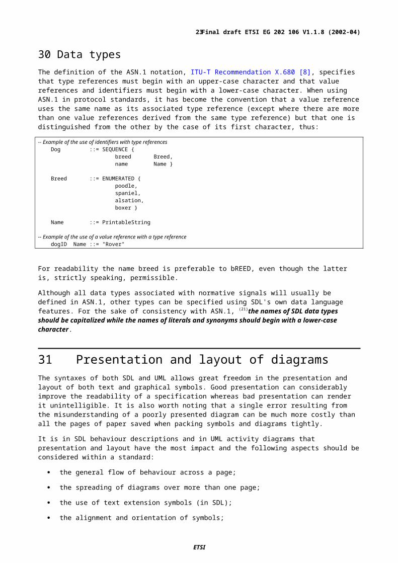
30 Data typesThe definition of the ASN.1 notation, ITU-T Recommendation X.680 [8], specifies that type references must begin with an upper-case character and that value references and identifiers must begin with a lower-case character. When using ASN.1 in protocol standards, it has become the convention that a value reference uses the same name as its associated type reference (except where there are more than one value references derived from the same type reference) but that one is distinguished from the other by the case of its first character, thus:
ETSI
Final draft ETSI EG 202 106 V1.1.8 (2002-04)18

-- Example of the use of identifiers with type referencesDog ::= SEQUENCE {
breed Breed,name Name }
Breed ::= ENUMERATED {poodle,spaniel,alsation,boxer }
Name ::= PrintableString
-- Example of the use of a value reference with a type referencedogID Name ::= "Rover"
For readability the name breed is preferable to bREED, even though the latter is, strictly speaking, permissible.
Although all data types associated with normative signals will usually be defined in ASN.1, other types can be specified using SDL's own data language features. For the sake of consistency with ASN.1, (21)the names of SDL data types should be capitalized while the names of literals and synonyms should begin with a lower-case character.
31 Presentation and layout of diagramsThe syntaxes of both SDL and UML allows great freedom in the presentation and layout of both text and graphical symbols. Good presentation can considerably improve the readability of a specification whereas bad presentation can render it unintelligible. It is also worth noting that a single error resulting from the misunderstanding of a poorly presented diagram can be much more costly than all the pages of paper saved when packing symbols and diagrams tightly.
It is in SDL behaviour descriptions and in UML activity diagrams that presentation and layout have the most impact and the following aspects should be considered within a standard:
the general flow of behaviour across a page;
the spreading of diagrams over more than one page;
the use of text extension symbols (in SDL);
the alignment and orientation of symbols;
the use of swimlanes (in UML – see EG 201 872 [3]).
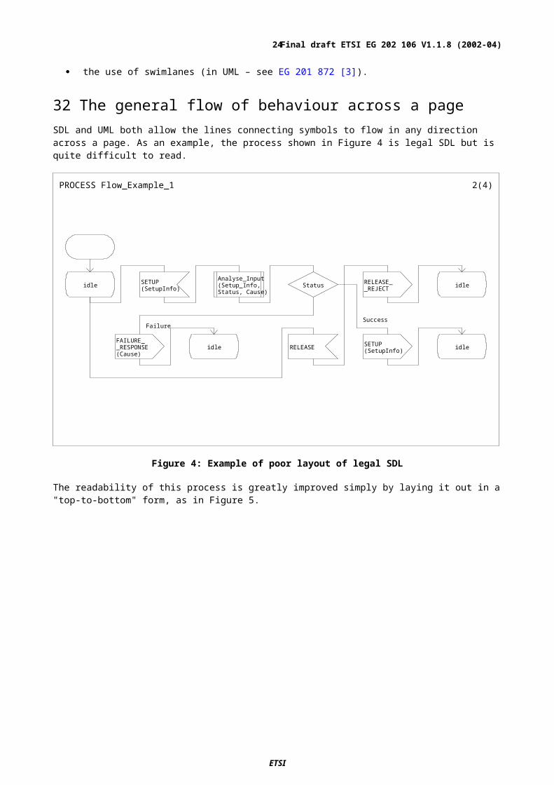
32 The general flow of behaviour across a pageSDL and UML both allow the lines connecting symbols to flow in any direction across a page. As an example, the process shown in Figure 4 is legal SDL but is quite difficult to read.
ETSI
Final draft ETSI EG 202 106 V1.1.8 (2002-04)19
PROCESS Fl ow_Exampl e_1 2( 4)
i dl e SETUP( Set upI nf o)
Anal yse_I nput( Set up_I nf o,St at us, Cause)
St at us RELEASE__REJ ECT i dl e
FAI LURE__RESPONSE( Cause)
i dl e RELEASE SETUP( Set upI nf o) i dl e
Fai l ur eSuccess
Figure 4: Example of poor layout of legal SDL
The readability of this process is greatly improved simply by laying it out in a "top-to-bottom" form, as in Figure 5.
ETSI
Final draft ETSI EG 202 106 V1.1.8 (2002-04)20

PROCESS Fl ow_Exampl e_2 2( 5)
i dl e
RELEASE
RELEASE__REJ ECT
i dl e
SETUP( Set upI nf o)
Anal yse_I nput( Set up_ I nf o,St at us, Cause)
St at us
FAI LURE__RESPONSE( Cause)
i dl e
SETUP( Set upI nf o)
i dl e
Fai l ur e Success
Figure 5: Example of improved layout
The orientation of flow between symbols in SDL and, to a lesser extent, in UML is naturally vertical and it is, therefore, easier to read diagrams that follow this convention. Thus, (22)the general flow of SDL behaviour diagrams and UML statechart and activity diagrams should be from the top of the page towards the bottom. However, in some UML instances the flow may be better expressed using a left-to-right flow across the page.
Even in class diagrams and others where there is no "flow" expressed, readability can be improved if there is a general top-to-bottom layout on the page based on hierarchy or some other pertinent characteristic.
33 Behaviour covering more than one page
34 SDL behaviour diagramsIn most cases within standards it is not possible to constrain SDL process descriptions to one page. Only two options exist for breaking a diagram across a page boundary without affecting the readability. These are:
using the NEXTSTATE symbol;
using a connector symbol.
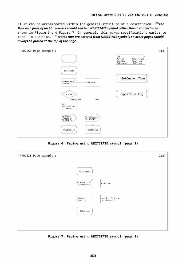
If it can be accommodated within the general structure of a description, (23)the flow on a page of an SDL process should end in a NEXTSTATE symbol rather than a connector as shown in Figure 6 and Figure 7. In general, this makes specifications easier to read. In addition, (24)states that are entered from NEXTSTATE symbols on other pages should always be placed at the top of the page.
ETSI
Final draft ETSI EG 202 106 V1.1.8 (2002-04)21
PROCESS Page_exampl e_1 1( 2)DCLAction RequestType;TimeNow TimeType;AckStatus AckType;
I dl eSt at e
Get Cur r ent Ti meUser Request( Act i on) Fr om User
Act i on Updat eUser Log
Get _Cur r ent Ti me( Ti meNow)
SendTi me( Ti meNow)TO SENDER
Test MessageTO SENDER
Wai t For Ack I dl eSt at e
Send_Ti me Test
Figure 6: Paging using NEXTSTATE symbol (page 1)
PROCESS Page_exampl e_1 2( 2)
Wai t For Ack
User Ack( AckSt at us) Fr om User
Updat e_User Log
( Act i on, Ti meNow, AckSt at us)
I dl eSt at e
Figure 7: Paging using NEXTSTATE symbol (page 2)
Although it would be possible to draw the example shown in Figure 6 and Figure 7 in a single thread with the WaitForAck state embedded part-way through, it is easier to locate individual states in a more complex specification if each thread is limited to a single transition (the processing between one state and the next one). (25)Where transitions are short and simple they can be arranged side-by-side on a single page as shown in Figure 8. However, (26)when two or more transitions are shown on one page, there should be sufficient space between them to make their separation clear to the reader.
ETSI
Final draft ETSI EG 202 106 V1.1.8 (2002-04)22
PROCESS Al i gnment _exampl e 1( 3)DCLCallParams ReqType,Result ResType,Cause ErrType;
TIMER T4 := 10*ms;
Const r uct _Er r or Si gnal
Anal yse
I dl eSt at e
Cal l Request( Cal l _Par ams)
Fr om User _1
Anal yse ( Cal l Par ams, Resul t )
Resul t
Const r uct _Onwar d_Request
( Cal l Par ams)
St ar t Ti mer( T4)
Cal l _Request( Cal l Par ams)
TO User _2
Wai t For _Request _Response
Const r uct _Er r or Si gnal( Cause)
Request _Er r or( Cause)
TO User _1
I dl eSt at e
Rej ect _RequestTO User _1
I dl eSt at e
Cl ear _Request
Fr om User _1
No cal l i n pr ogr essso i gnor e r equest
I dl eSt at e
Const r uct _Onwar dRequest
User Known User Not KnownCal l er _Not _Aut hor i sed
Figure 8: Transitions aligned on a single page
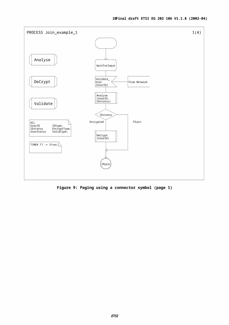
When a single transition extends beyond the length of one page, a connector symbol can be used to provide a link to the next page. An example is shown in Figure 9 and Figure 10.
ETSI
Final draft ETSI EG 202 106 V1.1.8 (2002-04)23
PROCESS J oi n_exampl e_1 1( 4)
DCLUserID IDtype,IDstatus EncryptType,UserStatus ValidType;
TIMER T7 := 3*sec;
Anal yseWai t For I nput
DeCr ypt Val i dat e_User( User I D)
Fr om Net wor k
Anal yse( User I D, I Dst at us)Val i dat e
I Dst at us
DeCr ypt( User I D)
I Ppr oc
Encr ypt ed Pl ai n
Figure 9: Paging using a connector symbol (page 1)
ETSI
Final draft ETSI EG 202 106 V1.1.8 (2002-04)24

PROCESS J oi n_exampl e_1 2( 4)
I Ppr oc
Val i dat e( User I D,User St at us)
User St at us
St ar t Ti mer( T7)
User _Val i dat ed( User I D)
VI A Net wor kUser _Not Val i dat ed( User I D)
VI A Net wor k
Wai t For I nput Wai t For I nput
Val i dat ed Not _Val i dat ed
Figure 10: Paging using a connector symbol (page 2)
As can be seen in Figure 9 and Figure 10, the syntax of SDL allows a connector symbol to have a process flow line to it or from it but not both. Figure 11 shows how it is possible for a connector to be attached to a symbol anywhere on a page. These can be difficult to locate and so, to avoid confusion, (27)connector symbols should generally only be used to provide a connection from the bottom of one page to the top of another. However, long transitions can often be avoided by careful use of procedures (see clause 46).
Label_5A := B + C
Update_Records(A)
Figure 11: Example of poor use of a connector symbol
35 Definitions in behaviour diagramsAn SDL process description (which may exist in a system, block or process diagram) should not be considered to be simply a "flow-chart" specifying a sequence of actions and decisions to be taken by a particular entity. In order to be complete, a process description may include the following:
a specification of formal parameters;
variable, signal and data definitions;
class and interface definitions;
ETSI
Final draft ETSI EG 202 106 V1.1.8 (2002-04)25
procedure references;
class reference;
the process graph, itself.
Symbols such as procedure references and text boxes containing DCL, TIMER and other declarative statements are valid for all pages of the process in which they appear. The SDL syntax allows them to be drawn on any page but, for easier reading, (28)all reference symbols and text boxes containing common declarations should be collected together at a single point within the process diagrams. For simple processes, and where space allows, these symbols can be placed together on the first page with the first transition, as can be seen in Figure 8 and Figure 9. In other cases, a separate page (or pages, if necessary) can be used to collect these symbols together.
To further improve the readability of the SDL, (29)separate text box symbols should be used for each different type of declaration (for example, variable declarations, timers, signal specifications, data type specifications and formal parameters). It can also be useful to sub-divide these groupings into separate text boxes according to application-specific criteria (for example, grouping all of the BOOLEAN SYNONYM definitions together).
36 UML activity diagramsUML does not support the concept of physical pages in its specifications but it may still be necessary to spread a distinct element of behaviour over more than one activity diagram. In this instance, there is only one mechanism that can be used for linking the diagrams and that is by using a state symbol. An activity diagram which terminates in a state other than the "End" state, will be assumed to continue at a subsequent instance of the same state in another activity diagram. In the example shown in Figure 12, the activity in the right-hand part of the diagram continues on from the "Connected" state on the left-hand side. Particularly in those cases where the specification of behaviour is distributed over many diagrams, (30)activity diagrams or statechart diagrams should use text boxes indicate what functions are specified in other diagrams or in which diagram the behaviour continues.
Figure 12: Example of UML activity diagram pages linked at a state
37 Text extension symbolsThe SDL symbols are not always large enough to contain all of the text necessary to specify the task represented by the symbol and if the character size is set to a value that makes it readable, the text spills over into the area surrounding the symbol as can be seen in Figure 13.
ETSI
Final draft ETSI EG 202 106 V1.1.8 (2002-04)26

Figure 13: Text overflowing a symbol
This can be difficult to read and, in the strict sense of the language, is syntactically incorrect. Therefore, (31)when the text associated with a task symbol overflows its symbol boundaries, a text extension should be used to carry the additional information as shown in Figure 14. The syntax of SDL specifies that the text in the extension symbol is added after the text in the task symbol. To avoid misinterpretation, care should be taken to ensure that the text extension symbol appears to the right of or below the task symbol unless all of the text is placed in the extension symbol. However, as a general rule the text extension symbol should not contain all of the text. For example, in the case of signals, the signal name should be placed inside the input or output symbol.
Figure 14: Use of Text Extension symbol
Even in cases where the text does not overflow the symbol, this is a useful presentation method which can be used to separate the signal name from the parameter list in inputs and outputs. For reasons of clarity, it is not advisable to split the parameter list between the primary symbol and the extension.
As an alternative to the use of a text extension symbol, SDL permits the re-sizing of both a task symbol and the text contained in it.
38 Alignment and orientation of symbols
39 AlignmentNeither SDL nor UML place any semantic significance on the placement and alignment of symbols but a process or activity page that is carefully arranged and not over filled with symbols and connecting lines will always be easier to read and interpret than one that is not.
ETSI
Final draft ETSI EG 202 106 V1.1.8 (2002-04)27
There is no particular benefit to be gained by aligning symbols of a particular type except that (32)symbols that terminate the processing on a particular page should be aligned horizontally to make it easier for the reader to identify all of the points where processing ceases or continues on a new page or thread. These symbols include:
In the example shown in Figure 15, the processing on the page can end in a number of different states. The alignment of all of the associated NEXTSTATE symbols at the bottom of the page makes it clear what all of these possibilities are.
PROCESS Al i gnment _exampl e 1( 3)DCLCallParams ReqType,Result ResType,Cause ErrType;
TIMER T4 := 10*ms;
Const r uct _Er r or Si gnal
Anal yse
I dl eSt at e
Cal l Request( Cal l _Par ams)
Fr om User _1
Anal yse ( Cal l Par ams, Resul t )
Resul t
Const r uct _Onwar d_Request
( Cal l Par ams)
St ar t Ti mer( T4)
Cal l _Request( Cal l Par ams)
TO User _2
Wai t For _Request _Response
Const r uct _Er r or Si gnal( Cause)
Request _Er r or( Cause)
TO User _1
I dl eSt at e
Rej ect _RequestTO User _1
I dl eSt at e
Cl ear _Request
Fr om User _1
No cal l i n pr ogr essso i gnor e r equest
I dl eSt at e
Const r uct _Onwar dRequest
User Known User Not KnownCal l er _Not _Aut hor i sed
Figure 15: Example showing the alignment of NEXTSTATE symbols
ETSI
Final draft ETSI EG 202 106 V1.1.8 (2002-04)28

40 OrientationMost SDL symbols are symmetrical and, thus, cannot be shown in different orientations. INPUT and OUTPUT symbols are different in that they can be shown either right facing or left facing, thus
SDL accepts both orientations as correct but does not assign any specific meaning to either. However, (33)in simple systems where each process communicates with only one or two other processes, the orientation of INPUT and OUTPUT symbols can be used to improve the readability of the SDL. However, to avoid possible specification errors and misinterpretation, explicit methods of identifying the source and destination of signals should be used. Symbol orientation should not be considered to be a substitute for the use of a "From" comment on an INPUT or the TO and VIA statements in an OUTPUT as described in clause 68. (34)If used, the significance of the orientation of SDL symbols should be clearly explained in the text introducing each process diagram.
41 Structuring behaviour descriptionsThe behaviour of an SDL system is mainly described in process diagrams which represent the topmost layer of the behaviour specification. Partial behaviour descriptions can also be described in procedures, methods and operators. For readability it is important that the behaviour specification is organized and presented in such a way that each reader can easily find information of particular interest. It is important to bear in mind that a standard is often read in different contexts at different times. For example, at one time it may be used to gain an overall understanding of the specification while at another time it may be read in order to extract some specific details.
42 Basic structuring principlesThe key structure within a protocol or service behaviour description is the relationship between a process state, the events that trigger some form of process reaction, the actions that are taken and the resulting state. Process graphs should be structured in such a way that these relationships are easy to see, as shown in Figure 16. (35)A state, input and the associated transition to the next state should be contained within a single SDL page.
ETSI
Final draft ETSI EG 202 106 V1.1.8 (2002-04)29

PROCESS Set up 2( 3)
Cal l _Est abl i shed
Rel ease( cal l I D) Fr om Cal l ed Par t y
Rel ease_Response vi a Net wor kLi nk
Rel ease( Cal l I d) vi a User Li nk
Rel ease_NW__r esour ces( Cal l I d)
Wai t For _Rel ease_Response
Figure 16: Simple transition
43 Structuring using procedures and operationsWithin a standard, the most important actions taken between process states are the generation of output signals. If the flow of control leading from one process state through input and outputs to the next state cannot be contained within a single SDL page, some of the detail should be hidden using procedures and operations, as described in clause 45 or composite states as described in clause 68.
44 Emphasizing the difference between normal and exceptional behaviour flowsWithin their textual descriptions, standards often make the distinction between normal and exceptional cases. This distinction can also be used effectively in the SDL. Figure 17 shows an example where the analysis result splits the flow into normal behaviour which is specified on the same page and error handling which is specified on another page. This allows the reader to concentrate on the normal behaviour and to look at the various error handling situations if and when that is required.
ETSI
Final draft ETSI EG 202 106 V1.1.8 (2002-04)30

PROCESS Dest i nat i onNode 2( 8)
I dl e
Set up( Cal l _Par amet er s)
Fr om Tr ansi t Node
Anal yse_Par amet er s
( Cal l Par amet er s, Resul t )
Resul t
Nor mal Behavi our
Set up_Response vi a Tr ansi t Net wor k
Wai t For _Connect i on
Er r or _Case
Except i onal Behavi ourdescr i bed on Page 5
Val i dPar amet er s El se
Figure 17: Part of process diagram showing only normal behaviour flow
The separation of normal and exceptional behaviour may also bring benefits to the standard development process, so that specification of normal behaviour becomes stable before error handling issues are addressed. Wherever it is appropriate and convenient, (36)process diagrams should segregate normal behaviour from exceptional behaviour. In such cases, it is also useful to use a text symbol to identify each page of a process as either "Normal Behaviour" or "Exceptional Behaviour", as shown in Figure 18:
ETSI
Final draft ETSI EG 202 106 V1.1.8 (2002-04)31

PROCESS Set up 3( 3)
/** Normal Behaviour **/
I dl e
( Cal l I d)Rel ease_Ter mi nal _Resour ces
f r om Cal l i ng Par t yRel ease_Response
Wai t For _Rel ease_Response
Figure 18: Labelled page of normal behaviour
45 Using procedures, operations and macros
46 ProceduresIn common with most programming languages, SDL procedures provide a mechanism for the modular specification of behaviour that can be used in different contexts.
An important aspect from the point of view of a standards specification is that procedures can be used to hide distracting detail. By moving detail to procedures, the reader is presented with a clear and concise overview of the required behaviour even though the detail can be viewed if it is required. (37)The use of procedures to modularize specifications and to 'hide' detail is strongly recommended.
As an example, there may be a requirement in a standard that the contents of an incoming message are analysed and that subsequent processing be based on the results of the analysis. The method of analysis is not an issue for the standard and, as can be seen in Figure 19, such detail can distract from the main purpose of the process. If, as is shown in Figure 20, the detail is removed to a procedure, the reader is left with the information that the message is to be analysed but without the distraction of how the analysis is undertaken.
ETSI
Final draft ETSI EG 202 106 V1.1.8 (2002-04)32

PROCESS Exampl e_1 2( 4)
Wai t _For __CONNECTED
CONNECTED( Set up__Resul t )
St at us : =Set up_Resul t !Cal l _St at us
St at us
Dest i nat i on : =Set up_Resul t !cal l ed_Par t y
Er r or Cause : =Set up_Resul t !Er r or Cause
Er r or _Cause
Cause : =User Er r or
Cause : =Net wor kEr r or
Cause : =User Er r or
Cause : =Net wor kEr r or
SUCCESS__RESPONSE ( Dest i nat i on)
FAI LURE__RESPONSE( Cause)
Connect ed I dl e
SuccessFai l ur e
User Not Known
NoRout eToUser I ncompat i bl eSer vi ces
NoNWResponse
Figure 19: Message analysis example without the use of a procedure
ETSI
Final draft ETSI EG 202 106 V1.1.8 (2002-04)33

PROCESS Exampl e_2 3( 6)
Wai t _For __CONNECTED Anal yse_I nput
CONNECTED( Set up__Resul t )
Anal yse__I nput ( Set up_Resul t , St at us,
Cause, Dest i nat i on)
St at us
SUCCESS__RESPONSE ( Dest i nat i on)
FAI LURE__RESPONSE( Cause)
Connect ed I dl e
Success Fai l ur e
Figure 20: Message analysis example using a procedure
47 Using procedures to replace informal tasksIn existing standards, it is common to see informal text included in an SDL task box as an item of useful, and often normative, information. For example:
Get user addressfrom the database
Stimulate therelease of the
basic call
and
NOTE: Although the text shown in the task symbols above is shown exactly as it most often appears in existing standards, it is important to recognize that without single quotation marks around it ('..') it is illegal SDL.
This notation is very easy to understand but it is not possible simulate or validate the action in the symbol. According to the strict definition of SDL, the text, "Stimulate the release of the basic call", is interpreted as a name at the start of an incomplete, and therefore incorrect, assignment statement. To make such expressions formal and executable, (38)convert informal text descriptions of actions into procedure calls and replace the task symbols with a procedure symbols, thus:
Get_UserAddress_From_Database
(UserId,UserAddr)
Stimulate__Release_of_
BasicCall
and
Note that in converting such text into a procedure call it may be necessary to add parameters to fully formalize the interface to the procedure.
ETSI
Final draft ETSI EG 202 106 V1.1.8 (2002-04)34

48 Procedure signature (parameters and returned values)A procedure interface specification identifies a set of parameters for the procedure and defines how these parameters are passed to and from the procedure. (39)All data relevant to the real behaviour represented by a procedure should be specified in the parameter list and returned value (if any). This means that a signature is specified which allows the contents of the procedure to be updated at a later stage without affecting the other parts of the specification.
The specification for a procedure signature can include
data items that are to be passed to the procedure (IN parameters);
data items that are to be passed back to the calling process. These can be specified as either IN/OUT parameters which are passed to the procedure and modified within it or OUT parameters which can only be passed from a procedure but not to it. These returned parameters can be specified as:
-a list of one or more items which appear in the calling statement. An example of a call to such a procedure is as follows:
-A single value associated with the procedure name itself. The following is an example of a call to a procedure of this type:
Figure 21 and Figure 22 show simple examples of each of these procedure types while Figure 23 shows how the procedures could be called.
( I N degC Temper at ur e) - > RETURNS Temper at ur e;
PROCEDURE Conver t _To_degF 1( 1)
DCL degF Temperature;
degF : = ( ( degC * 9) / 5) + 32
degF
Figure 21: Example of a value-returning procedure
ETSI
Final draft ETSI EG 202 106 V1.1.8 (2002-04)35
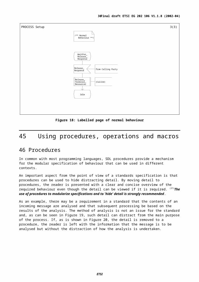
( I N degA Temper at ur e, OUT degF Temper at ur e, OUT degC Temper at ur e ) ;
PROCEDURE Conver t _Abs_To_F_and_C 1( 1)
degC : = degA + 273
degF : = ( ( degC * 9) / 5) + 32
Figure 22: Example of a procedure returning values in the parameter list
PROCESS Pr ocCal l Exampl e_1 2( 3)
Conver t _To_degF
Conver t _Abs__To_F_and_C
Wai t _For __Ther momet er _
_Readi ng
Recei ves Ther momet er r eadi ngi n Cent i gr ade, conver t s t o Fahr enhei t and sends i t out
Wai t _For __Absol ut e_
_Temper at ur e
Recei ves t her momet er r eadi ngi n Absol ut e, conver t s t o bot hCent i gr ade and Fahr enhei t andsends t hem out
READ__THERM( Temp_C)
READ__THERM( Abs)
Temp_F : =CALL Conver t __To_degF
( Temp_C) Conver t _Abs__To_F_and_C ( Abs, Fahr , Cent )
SEND_THERM( Temp_F)
SEND__THERM_F( Fahr )
Wai t _For __Acknowl edge
SEND__THERM_C( Cent )
Wai t _For __Acknowl edge
Figure 23: Examples of procedure calls
Procedures which return a value associated with the procedure call itself (Figure 21) can be used in place of variables in decisions, assignments, and output parameter lists to hide some of the detailed processing which is not essential to the understanding of a standard. However,(40) in most cases it is preferable to use operations instead of value-returning procedures.
ETSI
Final draft ETSI EG 202 106 V1.1.8 (2002-04)36

Procedures defined within the scope of the process calling them can access the variables belonging to that process. Accessing data in this way, particularly writing to a process variable from within a procedure, can result in a confusing specification. In order to avoid the possibility of this confusion and any other unexpected side-effects (41)procedures should only read and write to variables that are passed to the procedure in the parameter list or are declared within the procedure itself.
49 Procedure bodyThe behaviour specified within a procedure can be more or less complex depending on the application. In the example shown in Figure 20, the Analyse_Input procedure should be completed so that automatic tools can be used to check the syntax and semantics of the SDL. The following methods can be used:
1) provide a "dummy" procedure that does nothing (Figure 24);
this is adequate where the detailed behaviour of the procedure is not considered to be normative even though the overall function of the procedure may be. Figure 20 above is an example of this. It is important to include the dummy procedure in the standard as its formal parameters and results statements serve to define what, in a full implementation, the interface should be between the calling process and the function expected of the procedure.
2) provide a procedure that uses an ANY decision to arbitrarily return one of the possible values without actually specifying how the value is determined (Figure 25);
this is an ideal approach if the SDL model is to be validated by an automatic tool as it ensures that all possible result values are evaluated during the validation process.
3) provide a procedure that specifies in detail the behaviour expected (Figure 26).
this is the best approach in cases where the procedure has been used to hide complex behaviour but that behaviour is considered an important and normative part of the standard. It would also be advisable to use this approach when simulating the full behaviour of the model.
Whichever method is chosen,(42) procedures should specify a level of detail that is suitable for the particular purpose of the standard. At a minimum, the procedure should express the requirements it is modelling, even if this is simply a comment or a reference.
( I N Conn Connect Type, OUT Cause RespEr r Type, OUT Dest Par t yNumber ) ;
PROCEDURE Anal yse_I nput _Exampl e_1 1( 1)
/*The true purpose of this procedure would be to analyse the contents of a CONNECT message, extracting and returning the address of the called party if the call was successful or the error cause (UserError orNetworkError) if unsuccessful.Refer to Subclause 6.4.5 for a detailed description.*/
Dummy pr ocedur e wi t hno speci fi ed behavi our
Figure 24: Example "Dummy" procedure
ETSI
Final draft ETSI EG 202 106 V1.1.8 (2002-04)37

( I N Conn Connect Type, OUT Cause RespEr r Type, OUT Dest Par t yNumber ) ;
PROCEDURE Anal yse_I nput _Exampl e_2 1( 1)
/*Define a synonym to represent any party number. Only one value (1234) is generated.*/
SYNONYM TestPartyNumber = 1234;
Dummy pr ocedur e whi chgener at es out put par amet erval ues sui t abl e f or val i dat i on
ANYDeci si on woul d nor mal l y be basedon ' Cause' whi ch has t he l i t er alval ues, "NoEr r or " , " User Er r or " and"Net wor kEr r or "
Dest : =Test _Par t yNumber
Cause : =NoEr r or
Cause : =User Er r or
Cause : =Net wor kEr r or
/ *NoEr r or */ / *User Er r or */ / *Net wor kEr r or */
Figure 25: Example of a simple procedure suitable for validation purposes
ETSI
Final draft ETSI EG 202 106 V1.1.8 (2002-04)38

( I N Conn Connect Type, OUT Cause RespEr r Type, OUT Dest Par t yNumber ) ;
PROCEDURE Anal yse_I nput _Exampl e_3 1( 1)
DCLStatus CallStatusType,ErrCause ConnErrorType;
Pr ocedur e speci f yi ng par t i cul ar behavi our
St at us : = Conn! Cal l _St at us
St at us
Dest : =Conn! cal l ed_par t y
Er r Cause : =Conn! Er r or Cause
Er r Cause
Cause : =User Er r or
Cause : =Net wor kEr r or
Cause : =User Er r or
Cause : =Net wor kEr r or
Success Fai l ur e
User Not Known
NoRout eToUser I ncompat i bl eSer vi ces
NoNWResponse
Figure 26: Example detailed procedure
50 Avoiding side-effectsEach procedure should have a limited and clearly identifiable purpose which should fall into one of the following two categories:
1) Procedures that either analyse something or calculate something from input parameters and return a value that represents the result of the activity.
Some programming languages refer to this use of a procedure as a function. (43)A functional procedure should fulfil its specified role and do nothing that could be considered to be a side-effect. For example, a procedure that analyses the parameters received with a message should return a value that determines the future behaviour of the calling process. That behaviour may include sending of signals. (44)The processing of signals is one of the most important activities shown in the SDL of a protocol standard and should normally be visible in the calling process rather than the called procedure. Equally so, if the purpose of a procedure is to calculate something, it should do that and nothing else.
2) Procedures that generally do not return any value but have a limited sequence of actions to perform.
These actions are worth putting in the procedure provided that the same sequence of actions is repeated in many situations. In this case it may be appropriate that one or more related signals is sent from within a procedure. However, (45)it is important that procedures that specify a limited sequence of actions should be given names that reflect as fully as possible the activity performed by a procedure.
ETSI
Final draft ETSI EG 202 106 V1.1.8 (2002-04)39

In either case, (46)behaviour that could be considered a side-effect to its defined purposes, should not be specified in a procedure.
The specification of states within procedures obscures the processing of inputs and the overall synchronization of the calling process. Although not generally recommended, it is reasonable in some exceptional cases for a procedure to include the specification of states. Such situations are rare but an example would be a procedure which starts a 500ms timer and excludes all other processing until the timer expires. In this case, a state is necessary in order to receive the timer expiry
(47)In the exceptional case that a procedure includes the specification of one or more states, it is important to ensure that all signals which are not directly processed within the procedure are correctly handled for subsequent processing. This can be accomplished in one of the following ways:
- explicitly receiving all possible input signals in all states in the procedure;
- using the "SAVE all inputs" symbol which ensures that all signals that are not explicitly processed in the state are maintained as inputs until the next state is reached (see the example in Figure 27).
A simple example of a procedure containing a state symbol is shown in Figure 27.
PROCEDURE Del ay500ms 1( 1)
/* The timer T500 is definedin the calling process as follows:
TIMER T500 := 500*msec;
*/St ar t Ti mer( T500)
A macr o whi ch i s used t ost ar t t he t i mer .
Wai t __For _Ti meout
T500 / *Expi r y*/ * Save al l ot her i nput s t o be
r ecei ved i n t he cal l i ng pr ocess
Figure 27: Example of a procedure containing a state
51 Naming of proceduresProcedure names should follow the naming conventions described in clause 7 and should attempt to clearly reflect the purpose of the procedure without requiring detailed knowledge of the contents of the procedure (e.g., Analyse_SETUP). (48)The names of procedures having multiple effects should reflect each intended effect either individually or collectively. For example, a procedure that builds and then transmits a SETUP message might be named "BuildAndSend_SETUP".
ETSI
Final draft ETSI EG 202 106 V1.1.8 (2002-04)40
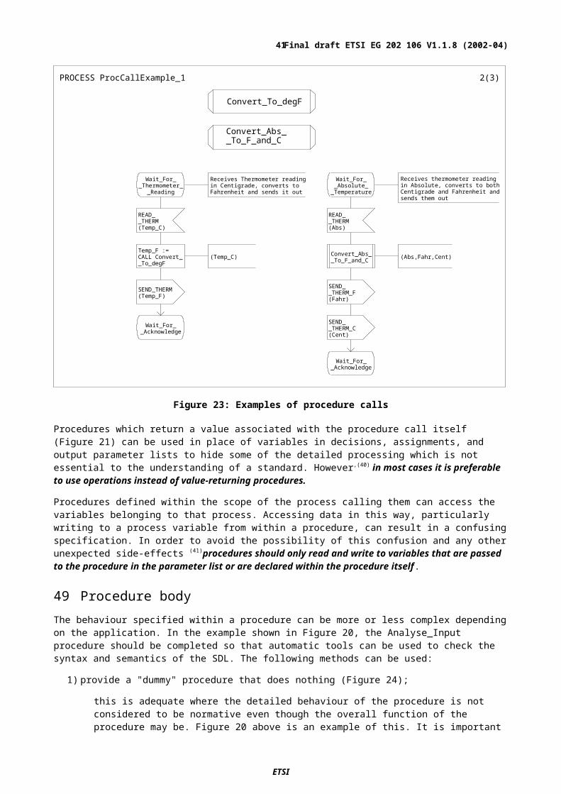
52 OperationsIn many situations operations represent a viable alternative to procedures. There are, however, some useful differences between them:
- operations are not permitted to have states;
- operations are not permitted to send signals;
- operations are permitted to access only parameters and variables declared inside the operation;
- operations may be used wherever procedures are valid but, unlike procedures, they can also be used in continuous signals.
Thus, operations inherently have many of the desired characteristics of value-returning procedures described in clause 50.
An operation is one of two kinds indicated by the keyword in the signature:
OPERATOR with a list of parameters. Must return a result and is used as an expression;
METHOD with a list of parameters. Has an optional result and must be applied to an expression (usually a variable but it can, for example, be a method application) by means of the dot notation (see Figure 31).
No general recommendation can be made on the choice of whether to use an operator or a method. If an object-oriented style were preferred, methods would probably be used, whereas for a more functional style operators would probably be used. In most cases a mixture of operators and methods could be used.
An OPERATOR may be thought most appropriate if the operation just uses values (all the parameters are IN parameters) to determine the result. An operator can be defined in any appropriate data type.
A METHOD may be thought most appropriate if the main purpose of the operation is to change the contents of a variable that it is applied to.
One of the simplest but most effective uses of operations is to improve the readability of expressions that contain data elements that need to be extracted from a complex data type. For example, consider the extraction of an OPTIONAL item of a field of a CHOICE data type, defined in ASN.1 as:
UnitData ::= CHOICE{ callInfo CallData,
packetInfo PacketData}
CallData ::= SEQUENCE{ callingParty PartyAddress,
callingSubaddress PartySubAddress OPTIONAL,calledParty PartyAddress,calledSubaddress PartySubAddress OPTIONAL
}
An assignment of the sub-address of a variable unitdata of this data type structure may look like this:
theSubAdd :=IF callInfoPresent(unitdata)THEN IF calledSubAddressPresent(unitdata.callInfo)
THEN unitdata.callinfo.calledSubAddressELSE noSubAddress FI
ELSE noSubAddress FI;
As well as being long to write, the statement also shows in detail how the element is accessed and the handling of a missing sub-address which is probably not relevant in the context of the function of the process.
The example in Figure 28 shows how an operator can be added to an inherited ASN.1 complex data type to perform the necessary extraction of the data element.
NOTE: Although most data types are specified in protocol standards using the ASN.1 notation defined in ITU-T Recommendation X.680 [8], operations can only be added in an SDL data type definition.
ETSI
Final draft ETSI EG 202 106 V1.1.8 (2002-04)41

Figure 28: SDL package where new data type containing an operation is specified
An operation is defined as part of the data type to which it belongs and has interface and body specifications similar to those defined for procedures. There is also a signature specification that introduces the operation name and specifies the types of parameters that it receives and returns.
Having defined the operator, the assignment statement can now be re-expressed as:
theSubAdd := called_subaddress_from(unitdata)
This assignment is shorter than the original, and it now shows the most useful information of what is extracted and where it originates.
(49)The textual syntax of SDL can be used to define simple operations such as the one shown in Figure 28. More (50)complex operations should be specified as operator or method diagrams which are referenced from the relevant data type specification.
An example of where an operation could be very useful is in the management of a circular counter that is permitted to have only a restricted range of values. Each time the value of the counter is incremented, there needs to be a check to determine whether the upper limit has been reached and, if so, counting needs to be restarted from the lowest allowed value. Instead of specifying it repeatedly in process diagrams, an operation can be used for this purpose. Figure 29 shows the necessary data type specification and includes the operator diagram reference. Figure 30 shows the operator diagram itself.
Figure 29: Data type containing the signature specification of a method
ETSI
Final draft ETSI EG 202 106 V1.1.8 (2002-04)42

Figure 30: Method diagram
The method defined in Figure 30 can usefully be applied to a variable in a loop as given in
PROCEDURE Dot Not at i onExampl e 1( 1)
DCL i Counter_1to20;
i : =1
f r eeci r cui t( i )
met hod i ncrappl i ed t oi wi t h dotnot at i on
i . i ncrELSE
1
Figure 31: Application of method from Figure 30 with the dot notation
Figure 32 shows how operators can be used to achieve the same effect as the procedure call shown in Figure 20. Three operators are used to extract status, error cause and destination address information from the Setup_Result parameter of the CONNECTED message. The intermediate Analyse_Input step is removed and, by choosing names for the operators carefully (Status_from, Cause_from, and Destination_from), the readability of the SDL is improved.
ETSI
Final draft ETSI EG 202 106 V1.1.8 (2002-04)43

PROCESS Exampl e_Oper at or Use 2( 3)
Wai t _For __Connect ed
CONNECTED( Set up_Resul t )
FROM Cal l edUser
St at usFr om( Set upResul t )
Success__Response
( Dest i nat i onFr om( Set upResul t ) )VI A User Li nk
Fai l ur e__Response
( CauseFr om( Set upResul t ) )VI A User Li nk
Connect ed I dl e
Success
Fai l ur e
Figure 32: Examples of operator invocation
The operator signature specification, with references to appropriate operator diagrams, for the above example is shown in Figure 33. The operator diagram for CauseFrom is shown as an example in Figure 34.
BLOCK exWi t hOper at or s 1( 4)
NEWTYPE Setup_Result_Type
/* only parts related to operator definition are shown */
OPERATORS Status_from: Setup_Resul_Type -> StatusType; Destination_from: Setup_Resul_Type -> DestinationType; Cause_from: Setup_Resul_Type -> CauseType;
OPERATOR Status_from REFERENCED; OPERATOR Destination_from REFERENCED; OPERATOR Cause_from REFERENCED;
ENDNEWTYPE Setup_Result_Type;
Figure 33: Example of data type definition containing operator signature specification
ETSI
Final draft ETSI EG 202 106 V1.1.8 (2002-04)44
( I N Conn Set upResul t Type) - > Cause CauseType;
OPERATOR CauseFr om 1( 1)
DCL ErrCause ConnErrorType; Oper at or speci f yi ng i n det ai l
t he der i vat i on of connect i onf ai l ur e cause
Er r Cause : = Conn! Er r or Cause
Er r Cause
Cause : = User Er r or
cause : = Net wor k_ Er r or
Cause : = User Er r or
Cause : = Net wor k_ Er r or
User Not Known NoRout eToUser I ncompat i bl e_Ser vi ces
NoNWResponse
Figure 34: Example of detailed operator diagram
53 Using macrosSDL provides a facility for specifying behavioural macros (i.e., a shorthand notation for functions which are repeated at several points within a specification). Macros may only be specified in a textual form and can be dangerous constructs which, if not used with extreme care, are likely to make a specification difficult to interpret and understand, particularly where the macro specifies a complex function. Thus, (51)the use of macros should be limited to those cases where the macro can be contained within one printed page.
There is one particular circumstance where macros can be used to add clarity and readability to a standard. In most protocol standards, SDL timers are controlled using the informal terms such as "Start Tn" and "Stop Tn". Unfortunately, SDL uses the keyword SET to start a timer and RESET to stop it. To avoid the use of SET and RESET (which is often misinterpreted to mean "re-start the timer") it is possible to define two macros for this purpose. SDL already uses the keywords START and STOP and so, in Figure 35 the macros have been named Start_Timer and Stop_Timer.
Figure 35: Macro definitions for starting and stopping a timer
ETSI
Final draft ETSI EG 202 106 V1.1.8 (2002-04)45

The example in Figure 36 shows how these macros can be used in practice. Note that the expiry of a timer in SDL is shown as an INPUT symbol simply containing the identifier of the timer. In this example, the word "Expiry" has been added as a comment for clarification.
PROCESS Di al l i ng Set up( 2)
TIMER T300 := 300*msec; Get _Set up_Par amet er s
I dl e
Cal l _Request( Dest i nat i on)
Fr om User
Get _Set up__Par amet er s
( Desi nat i on, Par ams)
SETUP( Par ams) VI A Net wor kLi nk
St ar t _Ti mer( T300) Macr o Cal l
Wai t For _Cal l _
Pr oceedi ng
CALL_PROCEEDI NG Fr om Net wor k T300
/ *Expi r y*/
Macr o Cal l St op_Ti mer( T300) Cal l Fai l ur e VI A User Li nk
Wai t For _Connect i on I dl e
Figure 36: Process illustrating the use of macros
54 Using decisionsConditional and optional requirements expressed in the textual version of a standard can often be represented in SDL as decisions or options. Decisions are used when the behaviour depends on current values of variable or expressions (clause 55). Options are used when the behaviour is fixed by the implementation (or non-implementation) of optional requirements (clause 66). Additionally, SDL algorithmic expressions permit the use of a range of conditional and looping statements for the control of textually-expressed behaviour (clause 67).
ETSI
Final draft ETSI EG 202 106 V1.1.8 (2002-04)46

55 DecisionsA decision symbol may contain:
informal text;
an expression that evaluates to a value of a certain data type, for example:
-a variable;
-a PROCEDURE call;
-an OPERATOR or METHOD application.
The use of informal text in decisions is described in clause 58. The remaining cases have the following in common:
the data type of the expression contained in the decision precisely determines the range of values that are acceptable;
each branch that follows a decision begins with the specification of an answer that determines the range of values for which that particular branch is to be taken. Such values can only be static and, thus, are not permitted to contain expressions that depend on variables or procedure calls.
(52)It is essential that the complete range of values of the data type contained in the decision is covered by ranges of values in the answers without any overlap. In this way it is possible to ensure that a unique execution branch is available for all possible results of a decision. The following errors can occur in the specification of a decision and should be avoided:
part of the range is not covered by an appropriate answer. This means that there is no path through the decision for such values and so further behaviour is unspecified;
the ranges of one or more answers overlap. In this case, more than one branch can be taken for a particular value and this would lead to is ambiguity;
the range of values specified in the answers is larger than the range of values of the data type contained in the decision. As a result, some branches may never be executed. This is likely to be confusing and would hamper readability.
56 Naming of identifiers used with decisionsSensible use of identifiers should ensure that a decision has a clear correspondence to the various alternatives expressed in the text. In addition to following the naming conventions expressed in clause 7 (53)identifiers used in decisions should clearly reflect to a reader the 'question' and 'answer' nature of the conditions being expressed.
57 Using decisions to structure a specificationDecisions can be used effectively to divide a specification into separate parts, each dealing with a particular aspect of behaviour. For example, it is quite effective to use a decision to segregate the normal expected behaviour from the exceptional behaviour. This approach can improve the readability of a standard and is illustrated further in clause 44.
It is sometimes the case that a standard needs to specify a complex decision tree based on a number of different parameters. An example of this might be the determination of an error cause based on a message received and the status of some internal data items. In most cases, particularly where the decision process is considered to be normative, it is not possible to simplify the presentation of the decision process by using alternative SDL constructs without losing clarity. Summarizing the decisions in a table before attempting to write the SDL can be helpful. Each decision should then be specified explicitly in the SDL and not hidden in a procedure or operator.
58 Use of text strings in decisionsThe simplest way of expressing the basis of a decision is to use informal text. This method is often chosen by specifiers for its readability. However, it is prone to errors as it gives no precisely defined relationship between the range of values acceptable in a decision and the range of values expressed in the answers.
ETSI
Final draft ETSI EG 202 106 V1.1.8 (2002-04)47

In the example shown in Figure 37, the implication is that the question is of a binary nature. Unfortunately, as that is not specified explicitly, other values, such as 'Minor error', could exist as part of the range results. The reader cannot be helped by automatic tools which are unable to detect such problems.
Figure 37: Use of informal text in a decision
NOTE: In a simulation environment the user would be prompted at run-time to choose a particular outcome. While this allows flexibility, it can make simulation cumbersome by requiring excessive interactive input.
As more possible outcomes are included in a decision expressed using informal text, there is an increased likelihood of an ambiguous interpretation of the result which automatic tools would be unable to resolve. Thus, (54)the use of informal text in decision statements should be limited, preferably to those cases where the decision is obviously binary in nature.
It is common in SDL specifications to omit the quotes (' ') around the text string. This is syntactically incorrect as the quotes should always be present.
59 Use of enumerated types in decisionsThe use of enumerated types results in a style which is similar in appearance to the example in Figure 37 but which has the additional and important benefit that a relationship between the question and answers is explicitly and precisely defined. The reader is made aware that there are no more than two possible outcomes. Furthermore, a tool can check that:
the contents of the decision symbol and the outcomes are compatible;
the value expressed for each outcome is within the enumerated range;
that all items in the enumeration have a possible outcome.
Figure 38: Use of enumerated types in a decision
NOTE: In this example a simulator would take one branch or the other depending on the actual value of CRC_Error.
ETSI
Final draft ETSI EG 202 106 V1.1.8 (2002-04)48
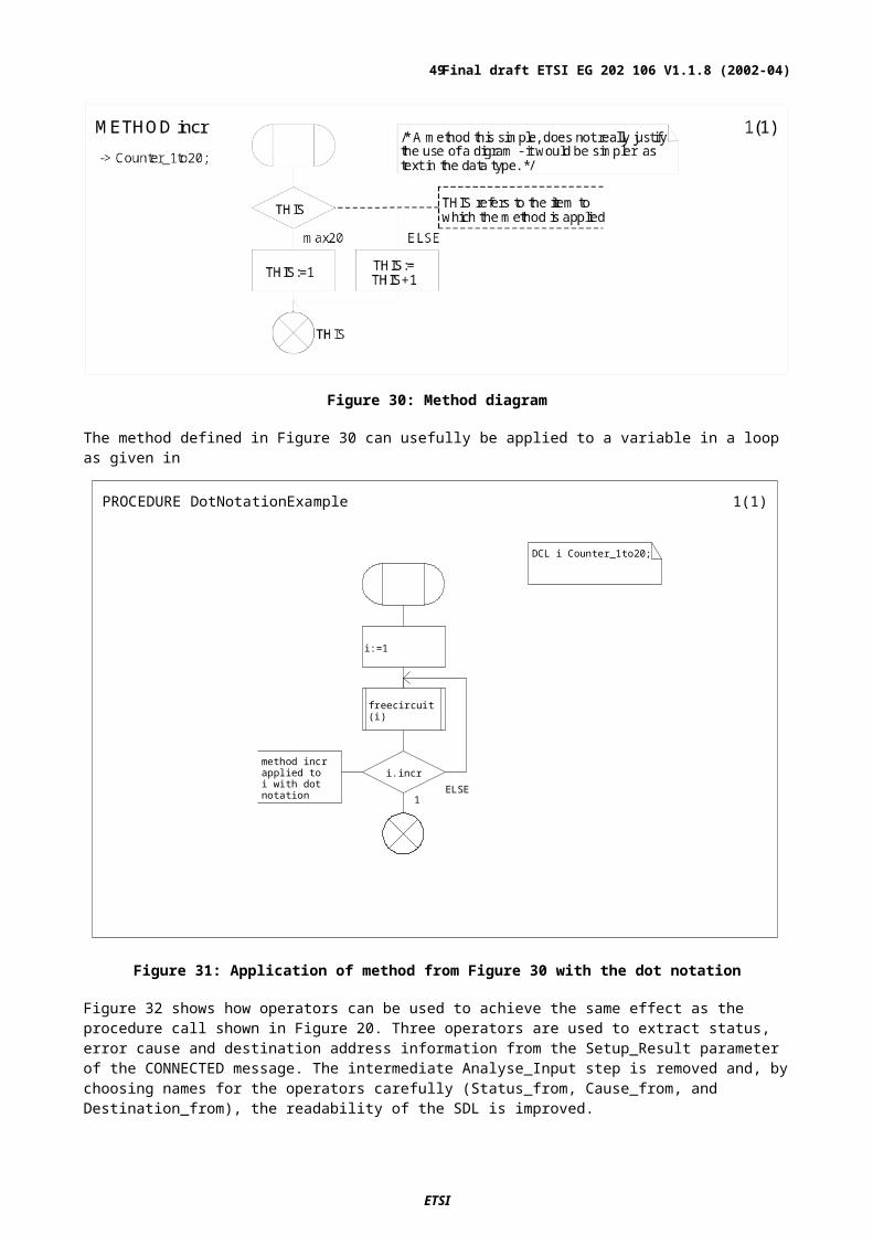
While this approach requires slightly more effort to declare the enumerated types and the associated variables, it produces a specification which is far less prone to error and aids understanding by allowing the grouping of related components such as error codes, service options and status values. (55)In most cases, enumerated types rather than text strings should be used to express decisions.
60 Use of ELSE
The use of the SDL built-in value ELSE is useful in completing ranges of outcomes. In the example shown in Figure 39, separate branches are specified for 7 200 bps, 9 600 bps and 14 400 bp while 28800bps and 33 600 bps are both covered by the ELSE.
Figure 39: Use of ELSE in a decision
Note that a precise interpretation of the ELSE construct is only possible if the range of values in a decision is defined by a data type (be it ENUMERATED or any other type).
(56)ELSE should be used as a decision outcome value to distinguish between one or more specific outcomes and all other possibilities.
61 Using SYNTYPES to limit the range of values in decisionsIt is often necessary to limit the range of values a particular data type can have. This is especially important in decisions where ELSE is used since it limits the range of values that lead to an ELSE branch. In most cases, the SDL concept of SYNTYPE or the ASN.1 constraint can be used to define a type that is basically the same as an existing type but which has a limited range. In the following ASN.1 and SDL examples, the type 'Digit' has all properties of 'Integer' but cannot take values that are less than zero or greater than 9.
ASN.1
Digit ::= INTEGER(0..9)
SDL
SYNTYPE Digit = Integer CONSTANTS (0..9);
Thus, (57)ASN.1 constraint or SDL SYNTYPE constructs should be used to limit the range of values represented by an ELSE branch in a decision.
ETSI
Final draft ETSI EG 202 106 V1.1.8 (2002-04)49
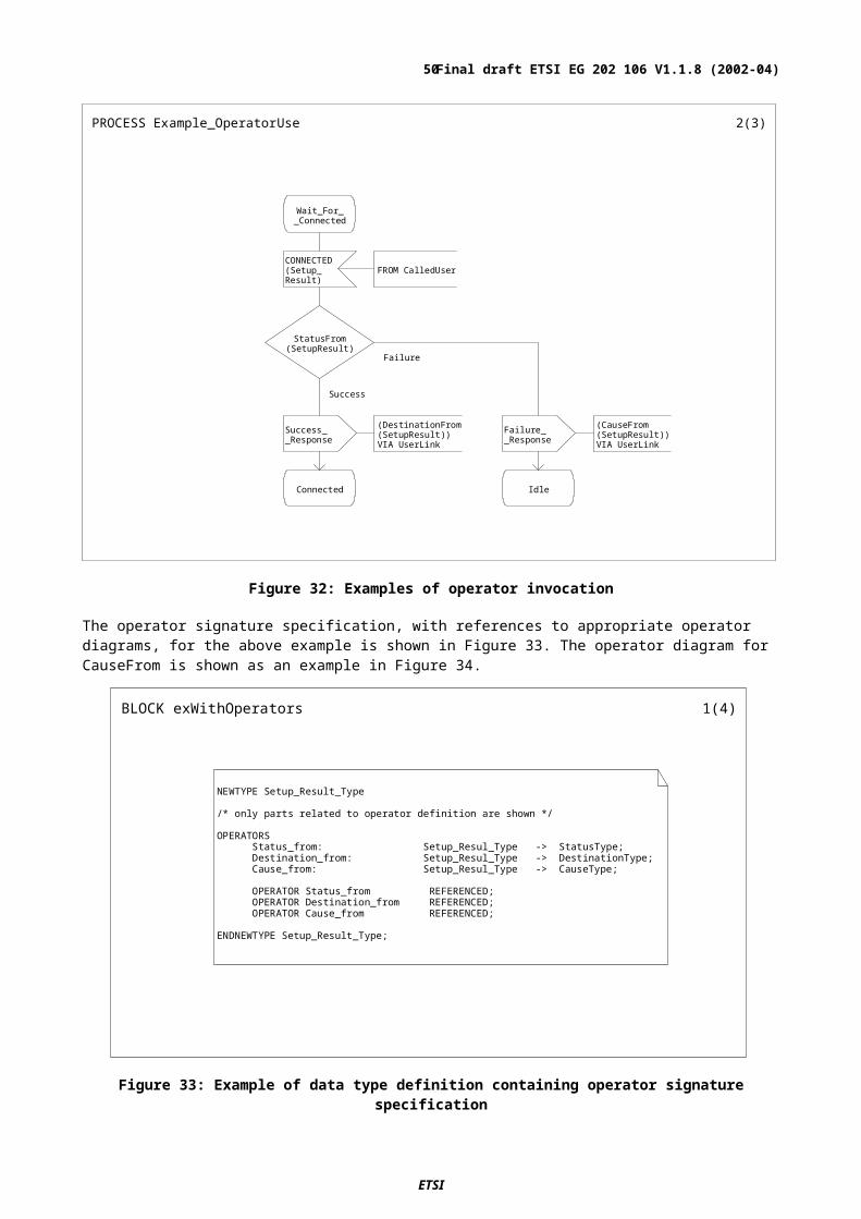
62 Use of symbolic names in decision outcomesIn many cases the content of the decision will be a boolean data type, which means that the values of true and false should be given in answers. (58)SDL SYNONYMs should be used to define meaningful alternatives to the Boolean values of true and false if this aids clarity. Figure 40 shows examples of the specification of Boolean SYNONYMs.
Figure 40: Examples of the specification and use of SYNONYMs with decisions
63 Use of range expressions in decisionsIn some cases, as shown in Figure 41, it is more meaningful to use comparisons to identify the possible outcomes from a decision.
Figure 41: Use of range expressions in a decision
ETSI
Final draft ETSI EG 202 106 V1.1.8 (2002-04)50
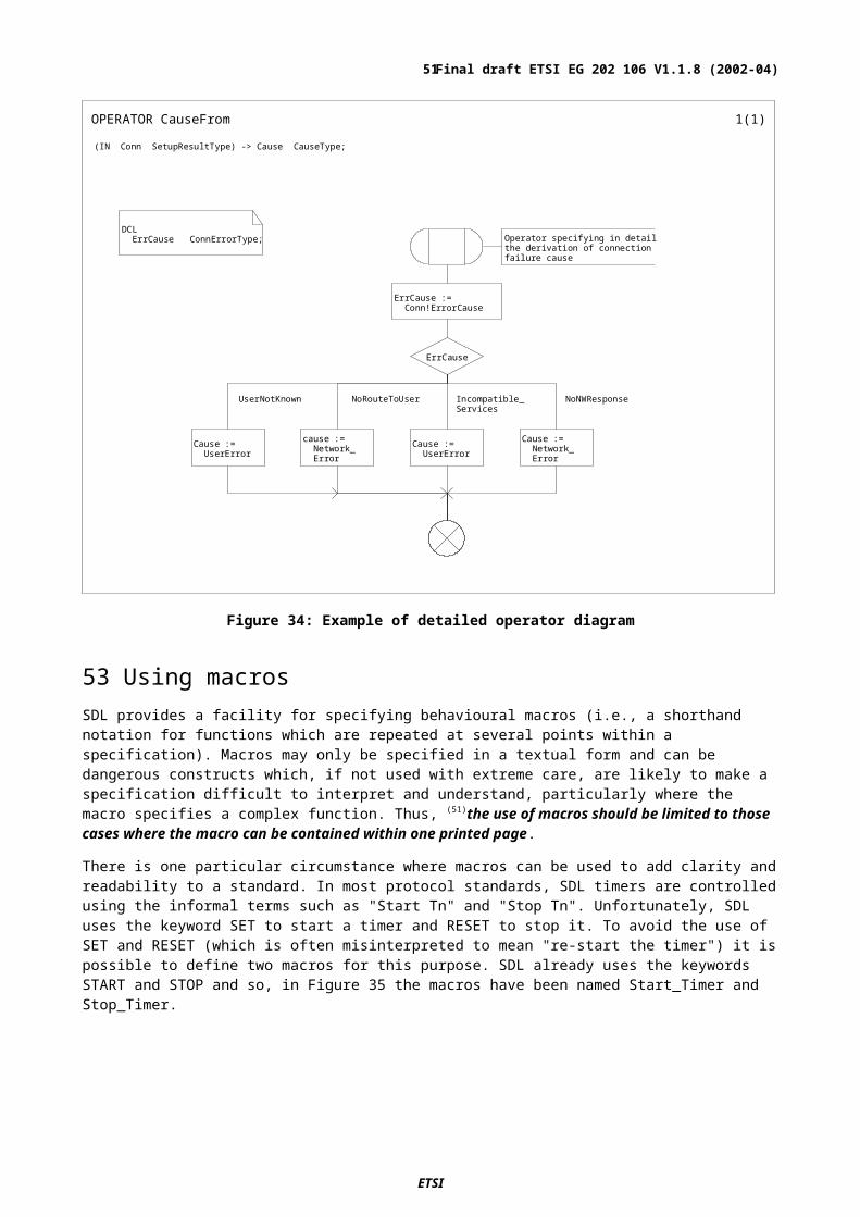
Although this explicit expression of outcome values is unambiguous, it lacks resilience to change. For example, if the value '10' was the maximum value that Ack_Counter should reach and it is used in numerous decisions throughout the specification, it would be very time-consuming to modify all relevant instances of 10 in the event that the requirement for the maximum value of Ack_Counter changes. For the purposes of flexibility and as described in clause 28, symbolic names rather than explicit values should be used to express decision outcome conditions. This approach is shown in Figure 42.
Figure 42: Use of symbolic names rather than explicit values
64 Use of Procedures in DecisionsIt is possible to use procedures in conjunction with decisions both to simplify the SDL and to improve its syntax without impairing its readability. As an example, the informal description shown in Figure 43 could be re-written in three ways using a procedure with the decision.
Figure 43: Informal task and decision
Note: The text in each of the boxes in Figure 43 is shown in single quotes. These have often been omitted in SDL diagrams within standards. This is illegal rather than informal SDL.
The first alternative is to call a value procedure directly from the decision, as in Figure 44. The procedure UserName extracts from the database the user's name associated with UserNo.
ETSI
Final draft ETSI EG 202 106 V1.1.8 (2002-04)51

Figure 44: Procedure called from within a decision
The advantages of this method are that it is concise and, in many cases, highlights only those aspects of the specification that are important to the standard.
It may be considered to be a disadvantage of this approach that in some instances it is too concise and hides normative requirements in the procedure.
The second alternative is to assign the result of the value procedure to a variable before making the decision based on the contents of the variable as shown in Figure 45.
Figure 45: Decision based on a variable assigned from a value procedure
The advantage of this method is that it can make clearer the individual steps involved.
The disadvantages are that an additional variable (Name) needs be specified and the assignment statement is less descriptive than the informal text.
In Figure 44 and Figure 45 the use of a PROCEDURE could equally well be replaced by an OPERATOR or METHOD application. Further details on the use of PROCEDURES, OPERATORS and METHODS can be found in clause 45.
ETSI
Final draft ETSI EG 202 106 V1.1.8 (2002-04)52
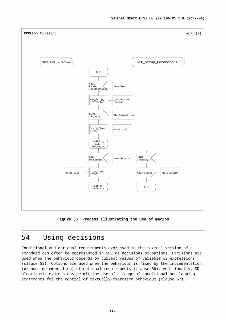
The final alternative is to call a procedure which returns a value as a parameter which is then used as the basis for the subsequent decision, as shown in Figure 46.
Figure 46: Decision based on a parameter returned from a procedure
The main advantage of this approach is that by careful choice of the name of the procedure, the SDL can be quite easy to read and understand.
The disadvantages are the same as those for the second alternative with the additional factor that returning the decision variable in a parameter can mask errors in the specification. As an example, if the procedure Get_UserName_From_DB did not determine and return a value in the Name parameter, this may not be detected by automatic tools and the decision would be based on whatever value had previously been assigned to Name.
All of the three alternatives above are valid methods and it is a matter for the rapporteur to decide which is the most appropriate on a case-by-case basis. Whichever one is selected, (59)procedure calls should be used in conjunction with decisions to eliminate the use of informal text.
65 Use of ANY in decisionsFor validation purposes, it may be necessary to re-specify decisions using the non-deterministic ANY expression. However (60)the ANY expression should not appear in the SDL specifications in standards except where it is included to show the behaviour of an entity (such as a user) that is not the subject of the standard.
66 Use of options rather than decisionsThe dynamic nature of decisions is not well suited to the expression of the implementation options which are often to be found in protocol standards. Fortunately, SDL includes a symbol (Figure 47) specifically for this purpose. The processing path through this symbol is evaluated at system generation time based on the static value provided for the optional item. This path is then fixed until the system is re-generated with a different value of the optional item.
(61)Where mutually exclusive implementation options are to be expressed, the option symbol should be used rather than a decision.
The most effective way of labelling the paths leading from an option symbol is to define appropriate synonyms.
ETSI
Final draft ETSI EG 202 106 V1.1.8 (2002-04)53

Figure 47: Use of SYNONYMs with options
NOTE: A practical problem can occur with a specification model that has many options and which is to be used for validation purposes. In such cases the 'hardwired' nature of SDL options makes this cumbersome as each new combination will require a new compilation of the executable model. Decisions together with some form of parameterization would provide a more flexible approach.
67 Flow control statementsThere are some specification tasks for which the SDL graphical symbols are not ideally suited. One example of such a task is the calculation of the polynomials required by authentication procedures. For these cases it is possible to use SDL algorithmic expressions which are based on a structured textual language. Within this language there are a number of flow control statements, thus:
IF statement
equivalent to an "IF…THEN…ELSE" construct;
DECISION statement
equivalent to a "CASE" construct;
LOOP and CONTINUE statements
equivalent to a "WHILE" construct but can also be use as a "FOR….STEP….NEXT";
"BREAK" and "LABEL" statements
equivalent to a "GOTO label" statement.
These statements are very powerful but, for obvious reasons, lack the clear presentation of the graphical form. However, they are generally more compact and easier to interpret in the specification of either very simple tasks or more complex algorithmic computations. (62)SDL algorithmic flow control expressions should be restricted to situations where the required behaviour involves only the processing of data but not the sending of signals and not the control of timers. When there is a good reason for using them, the clarity of a specification can be improved by defining algorithmic expressions in procedures with meaningful names indicating the function(s) performed by them (see clause 45).
Figure 48 shows an extract of an SDL process diagram which takes a value received in the UserQoSRequest signal and calls the Determine_RValue procedure to obtain values of Requested_Rval and Availability_Type. The text procedure specification in Figure 49 extracts QoS_Class from the IN parameter and uses that as the control variable in a DECISION statement which assigns values to RvalReq and Av_Type.
ETSI
Final draft ETSI EG 202 106 V1.1.8 (2002-04)54
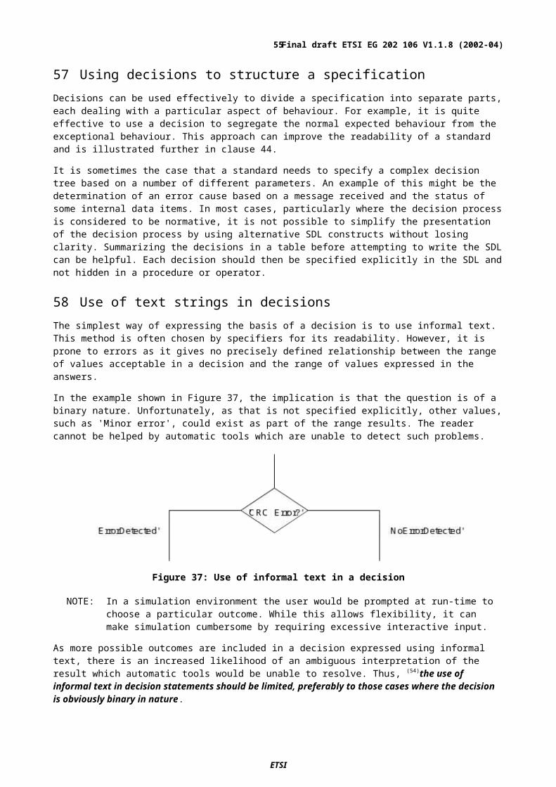
PROCESS FE1 2( 3)
I dl e
User _QoSRequest( R_Request )
Fr om Cal l i ng User
Det er mi ne__Rval ue
( R_Request , Request ed_Rval ,Avai l abi l i t y_Type)
Avai l abi l i t y_Type
Nor mal _Behavi our
Except i onal _Behavi our
Guar ant eed Not Guar ant eed
Figure 48: SDL calling an algorithmic expression in a procedure
Figure 49: Text procedure using DECISION statement
ETSI
Final draft ETSI EG 202 106 V1.1.8 (2002-04)55

68 System structure, communication and addressingAlthough one of the principle aims when using SDL in a descriptive manner is to provide a readable specification that concentrates on describing what the system is supposed to do (requirements) rather than on the detail of how the system is to be implemented, SDL has some inherent structure. The simplest model needs to identify communication with the environment, the pieces that make up the SDL and the addressing of communication. A useful technique for hiding detail at various levels of complexity is the layering of information (sometimes called data hiding) where pieces of the SDL contain other pieces, the details of which are hidden from the highest level. An SDL system description therefore defines the structure of the visible system pieces, and each of these in turn can contain structure and behaviour.
NOTE: The structure and readability of an SDL specification with respect to its graphical layout is considered in clause 41 and the use of data for signals in clause 93.
69 System structureSDL allows the layered specification of systems such as protocols or services in a hierarchical manner through the use of agents: system, blocks and processes. Usually the system and block agents define the static architecture of the system, whereas process agents that are contained in a block or system define its dynamic behaviour. Although a block can be defined to have a state machine, if state machine descriptions are restricted to agents that are processes, the block and process symbols then give a clear indication of which agents have their own behaviour and which do not. A very simple system may consist of a system agent containing a single process.
The SDL system and block structuring give an unambiguous description of the system architecture. It is usual that architectural aspects are described elsewhere in a standard (or even in other standards) often using non-SDL figures. If this is the case then (63)the SDL version of the architecture of a protocol or service should be consistent with and complementary to other (non-SDL) descriptive diagrams. This is particularly important in relation to naming, which facilitates the easy identification of system components. In addition, (64)comments should be used to convey to the reader the relationship of the SDL architecture to the relevant non-SDL parts of the standard. If the structure of the system is specified in SDL, informal drawings that duplicate structural information given by the SDL diagrams should not be used. This may mean including SDL system diagrams in the parts of the document where structure and architecture are discussed.
The major advantage of SDL structure diagrams is that their meaning is well defined, so that the document does not rely on intuitive understanding of an informal drawing or introduce an explanation of the notation used. Of course, many issues (such as physical attributes of equipment) cannot be described in SDL, and other well-defined notations may also be used.
An SDL specification is incomplete if it includes behaviour descriptions in agent diagrams but does not include the associated structure diagrams. For example, a system diagram containing agents and the channels connected to the agents defines the structure of the system. Even in the case of a simple protocol or service,(65) the SDL specification within a standard should comprise one system composed of at least one agent. This is not simply a case of ‘getting the SDL right’ for the sake of it. The SDL architecture provides useful information for the reader such as what entities and communication paths exist within the system. There is usually more than one connection with the environment and different channels connected to the frame in the SYSTEM diagram show this. The communication paths have an important role in the addressing of messages from one behavioural part to another.(66) SDL should be used to show the structure of a system as well as its behaviour.
NOTE: SDL block and process agents define the functional partitioning of the system. Using SDL does not imply that a real system need implement a standard exactly as defined by the SDL, only that the implementation should exhibit external behaviour over the normative interfaces that is equivalent to the behaviour defined by the SDL model.
In a complex standard it is possible that the SDL description only covers part of the system. It may also be necessary to include sub-structuring that is only implied in the text but which is needed to give a coherent and complete SDL model. It is not possible to give strict guidelines on how to structure a specification, as this will depend on the subject matter of the standard. However, although the careful use of sub-structures can make a complex specification easier to understand, the overuse of sub-structures can render them unreadable. (67)SDL sub-structuring should be used to simplify complex SDL models but should not be used excessively.
ETSI
Final draft ETSI EG 202 106 V1.1.8 (2002-04)56
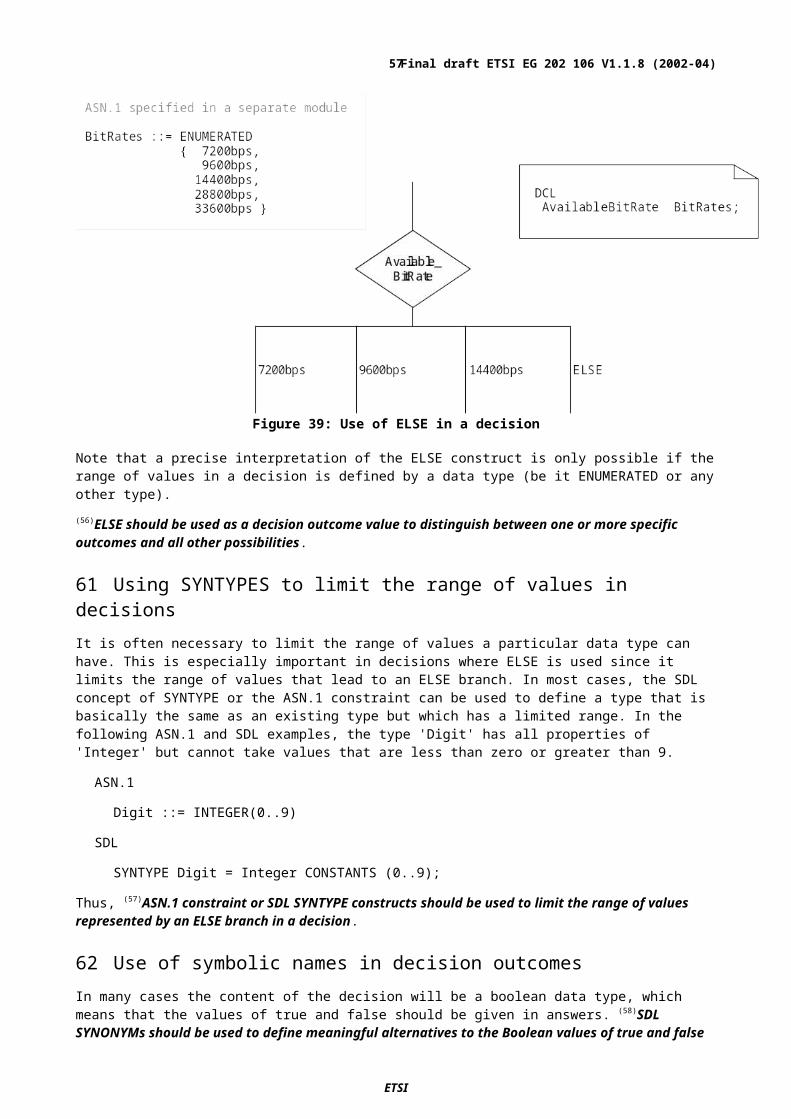
70 Minimizing the SDL modelThe example in Figure 50 shows a situation where there are a large number of identical user terminals communicating with one of several identical local concentrators, which are all connected to a single common network.
terminalconcentratorterminal
terminal
terminal
concentratorterminal
terminal
terminal
concentrator terminal
terminal
terminal
Network
concentrator terminal
terminal
terminal
Figure 50: A hypothetical network
Since the terminals all have the same behaviour, it would be possible to describe the system by providing a single description for a terminal that is replicated several times. Similarly the concentrators could be replicated and the corresponding SDL model for an implementation might be as shown in Figure 51. Note that Figure 51 shows only the first page of the SYSTEM diagram and the interface definitions (for toUser, fromUser, toConc, fromConc, toNetwork and fromNetwork) and synonym definitions (for NumberOfTerminals and NumberOfConcentrators) are defined on the second page (not shown here). In general, while Figure 51 is perfectly acceptable for the specification of an operational system, it is unnecessarily complex for describing protocols and services in standards. What needs to be captured in a standard is the minimum that implementations should conform to, and a standard needs to make clear the role of each entity involved.
ETSI
Final draft ETSI EG 202 106 V1.1.8 (2002-04)57
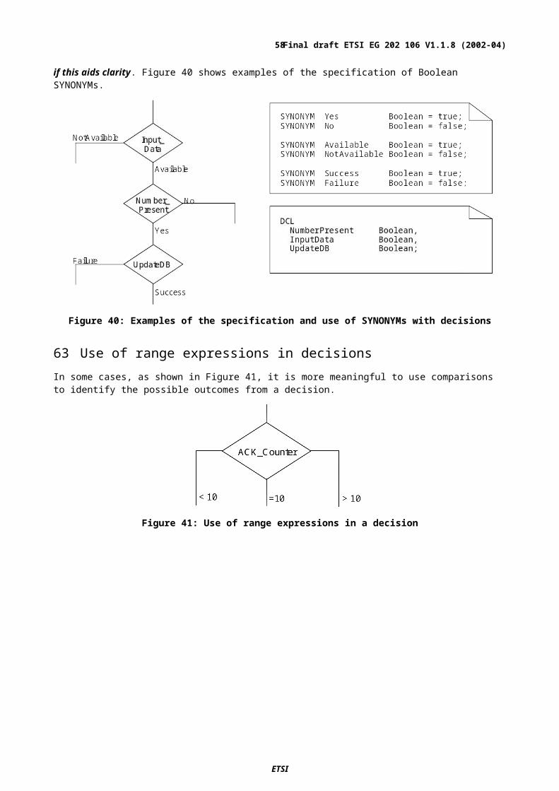
Figure 51: An SDL system model appropriate for implementation of the network in Figure 50
In the example, it would be sufficient to describe the protocol in terms of an origination terminal, a destination terminal, an origination concentrator, a destination concentrator and the network as shown in Figure 52. Each block represents a particular role and the unnecessary complexity of multiple instances shown in Figure 51 is removed.(68) Multiple instances of SDL blocks and processes should be avoided if possible.
Figure 52: A simplified SDL system model for the network in Figure 50
Sometimes informative blocks and processes (such as OriginationTerminal and DestinationTerminal in Figure 52) are needed to aid the understanding of a standard, and to describe the behaviour of entities surrounding the functions that are the subject of the standard. If the terminal and network behaviour is not needed for the concentrator-to-concentrator example, an SDL system such as Figure 53 with only the different end functions can be used. (69)Informative blocks or processes that are not needed to aid understanding should be omitted, because such detail will obscure the minimum requirements expressed by the standard.
ETSI
Final draft ETSI EG 202 106 V1.1.8 (2002-04)58

Figure 53: A minimal SDL model for the concentrator protocol standard example (distinct ends)
Protocols can be modelled effectively by showing the functionality of the ends separately as shown in Figure 53. This has the advantage that the description can be simplified so that only the functionality essential to the protocol is defined. It is assumed that in this case each concentrator is sufficiently simple that it can be modelled by just one process. It is more likely that blocks with contained processes will be needed, as shown in subsequent diagrams. When a block contains only one process, replacing the block by the contained process reduces the complexity of the SDL. A diagram can contain both blocks and processes.
71 Avoiding repetition by using SDL typesIn some specifications, there may be structure and behaviour that is replicated in more than one block or process. To avoid repetition, (70)if the same block or process is required at more than one place within an SDL specification, a BLOCK TYPE or PROCESS TYPE should be defined from which instances can be derived.
72 Defining the same behaviour at both ends of a protocolThe use of SDL types is particularly useful for standards that specify the behaviour of both ends (such as origination and destination) of a protocol communication as a single, multi-purpose entity as in Figure 54. With this approach, the function of each end of the protocol is not so distinctly separated but actual functional behaviour is specified only once (in the BLOCK TYPE Concentrator in the example).
Figure 54: A minimal SDL model for the example where the same function is used at each end
73 Static instances to represent repeated functionalityIn some cases, a standard may suggest that process instances need to be dynamically created. Dynamic creation of entities usually adds unnecessary complexity in the addressing of entities and should only be used in the (rare) occasions that it is essential. If, for example, there is a multi-link concentrator standard, one origination concentrator and two destination concentrators, as shown in Figure 55, may be sufficient. In this case, it is appropriate to use the BLOCK TYPE DestConc because the two destination concentrators have the same functionality.(71) Wherever possible, a minimal number of static instances should be used instead of dynamically created SDL processes.
ETSI
Final draft ETSI EG 202 106 V1.1.8 (2002-04)59

Figure 55: Static SDL model for a multi-link scenario
74 InterfacesAn SDL interface is a type that defines a set of communication items (signals, remote procedures and remote variables) realized by an agent or at one gate of an agent. The interface name can be used wherever a signal list is required (for example on a channel or in an input) and the communication items included in the interface are then used as the signal list. In this respect an INTERFACE definition and a SIGNALLIST definition are equivalent.
All the communication items of an interface can be defined inside the INTERFACE definition as part of the interface. By contrast, communication items used in a SIGNALLIST have to be defined separately. An INTERFACE definition can therefore more clearly identify and group together the relevant items.
It is preferable to use an interface definition rather than a signallist definition to give an identity to a set of communication items (signals, remote procedures and remote variables).
An INTERFACE definition has additional properties compared with a SIGNALLIST:
1) An interface can inherit other interfaces (and unlike other types in SDL can inherit more than one interface) for example:
INTERFACE callHandling INHERITS setupPDUs, terminationPDUs;
In this case callHandling inherits all the items defined in setupPDUs as well as all those defined in terminationPDUs. For any item, such as a SIGNAL named Setup, defined in setupPDUs there is a corresponding item defined in callHandling. The SIGNAL named Setup in callHandling is distinct from that defined in setupPDUs and if necessary they can be distinguished by a qualifier as in:
<<INTERFACE callHandling>> Setup
By comparison when one SIGNALLIST definition includes the name of another SIGNALLIST definition as an element, there is no re-definition of the included signal.
ETSI
Final draft ETSI EG 202 106 V1.1.8 (2002-04)60
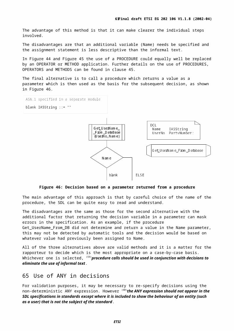
2) Every agent and agent type has an associated implicit interface (with the same name) that realizes the communication items of the agent or agent type; that is, all signals, remotes procedures or remote variables handled by the agent or agent type.
3) An interface definition name can be used to name a (uni-directional) gate, which defines that the gate has the communication items of the interface as its signal list, for example as in Figure 56 where DocService is used for interface gate definitions.
Figure 56: BLOCK TYPE using an INTERFACE realized by another BLOCK TYPE
NOTE 1 Any block type that inherits DocServerType also realizes the DocService interface.
NOTE 2 Agent types that are completely unrelated to DocServerType might also implement the DocService interface.
Figure 57: BLOCKs using interfaces realized by two other type-based BLOCKs
Because an interface gate has the name of the interface and the list of communication items of an interface can also be denoted by the interface name, it is common for the same name to appear as a signal list on a channel and the gate at receiving and of the channel. Figure 57 shows instance sets based in the types defined in Figure 56. Unnamed channels convey the signals of the INTERFACE DocService to gates that are also named DocService.
75 Diagrams showing relationshipsFor more complex systems it may be useful to include a specification area diagram to give an overview of what is included in the system. (72)A specification area diagram (if used) should include the most important packages shown as reference symbols with dependency shown on the diagram. For example the DocSys depends on the packages DocPack and ServPack, which both depend on FilePack. The diagram shows what packages are needed in addition to the SYSTEM DocSys. If any of the packages is defined in another document, this can be shown by annotation or by the name of the package.
ETSI
Final draft ETSI EG 202 106 V1.1.8 (2002-04)61
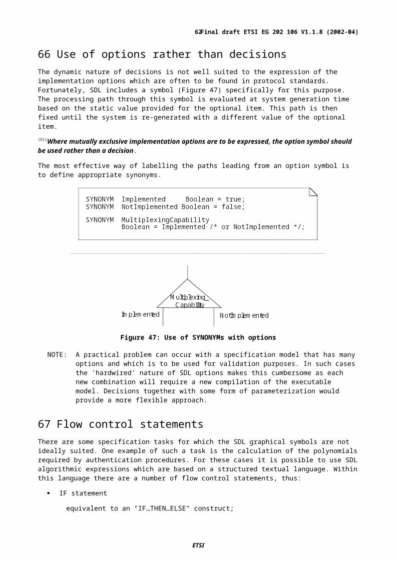
Figure 58: A specification area diagram giving an overview of packages included in a system
Types used within the system are either defined within a package or within an agent diagram of the system and the relationships between types can be shown in these diagrams together with package dependency of types.
The partitioned symbol shown in Figure 59 is used to refer to a class in UML or a type in SDL. In the following the UML terminology "class symbol" is used. The class symbols include a partial (possibly empty) specification of attribute and behaviour properties that must be consistent with the full specification given where the entity is defined.
Class symbols for types defined in different scopes can be collected together on the same diagram, so that a model showing relationships between the types can be drawn.
NOTE: class symbols that reference non-local types have no impact on the meaning of the SDL, so can be included or omitted as needed. A non-local reference is by a qualified identifier rather than a name.
Figure 59: Partitioned "class" symbol – used to refer to an SDL type
76 Use of associations between class symbolsAssociations can show relationships between class symbols items. Inheritance, dependency, and context parameterization can also be shown. Typically an association that is not inheritance or dependency is realized by communication between interfaces. For example, in Figure 60 the subscription association could be realized by the blocks communicating using the Calling and Called interfaces, though this does not have to be the case.
Figure 60: A named association between two block types
Associations need not be related to any direct interface connection between the types, as illustrated by Figure 61 where there is a relationship between definitions based on the Usertype and definitions based on the Managetype.
ETSI
Final draft ETSI EG 202 106 V1.1.8 (2002-04)62

Figure 61: Class symbols with inheritance and a named association
Class symbols are always references to a more complete definition that is given elsewhere. There can be one or more class symbols for the same type and the amount of detail about the type can differ in each case. This avoids the problem of trying to show everything about a type in a unique class symbol for the type. Figure 60, Figure 61, Figure 62 and Figure 63, could all be part of one SDL diagram, though it is most likely that each would be on a different page because they cover different issues.
NOTE: The arrowheads on associations are open, compared with filled arrowheads on gates and channels.
77 Use of a class symbol for an INTERFACE definition
Figure 62: References for interfaces
Although the properties of an interface can be shown in a class symbol as in Figure 62, there still needs to be a separate definition of the interface in a text symbol. The class symbol and the corresponding definition must be consistent. The class symbol for an interface can be used to highlight the most important items of the interface, and enables associations of the interface with types to be shown graphically (see 76).
Class symbols in diagrams could be used to show interfaces graphically together with the agent types that can communicate by the interfaces. The interfaces may be shown as interface gates such as Called, Calling and MgtIf on Nettype in Figure 63. The symbols in Figure 62 and those in Figure 63 could be conveniently placed on the same page of a diagram.
Figure 63: Interface gates using the interfaces referenced in Figure 62
78 Structure diagrams using interfaces between agentsAs can be seen above, class symbols can be used in SDL diagrams in a similar way to UML class diagrams. One of the major differences between SDL diagrams and UML class diagrams is the definition of a structure in a type. The structure shows the communication paths between agent definitions in the type and bounds on the number of instances. The structure defined in a type is used in definitions based on the type and in sub-types. In Figure 64 the types from the
ETSI
Final draft ETSI EG 202 106 V1.1.8 (2002-04)63

class symbols in Figure 60, Figure 61, Figure 62 and Figure 63 are used for the type based block definitions. A channel has been drawn between User and Net to define the communication link instances. This channel is connected to the outgoing interface gate Calling and to the incoming interface gate Called in User. Similarly the channel is connected to the interface gates Called and Calling in Net. The signals conveyed by the channel are shown by the use of the INTERFACE names Calling and Called associated with the arrowheads of the channel, though these could have been omitted because they can be derived from the channel connections (as has been shown for the unnamed channel for the interface MgtIf).
Figure 64: A type containing structure with instances of other types
79 Communication and AddressingUsing signals on channels effects communication between (block and process) agents in an SDL system and with the environment. A signal is conveyed from the connection at one end of the channel to the connection at the other end, where the signal is either delivered to another channel or to the state In simple models, there will only be one agent instance or connection with the environment that a particular signal can reach from the state machine that outputs it, and no further addressing is needed. Similarly, in simple systems for a particular signal arriving from the environment on a channel there will just one agent instance that can consume the signal.
At least one channel should represent the normative interface(s) of the system being specified and (73)all normative channels (interfaces) should be clearly marked as being normative (using a comments box), with the assumption that channels not marked as normative are informative and that they have been introduced into the SDL for clarity and completeness only.
SDL processes are concurrent (usually – but see 88), so it is possible that signals from different processes on the same communication path could be interleaved. If there are two different paths from a sending process to a receiving process, it is possible for messages to arrive in a different order from the order in which they were sent. To avoid this,(74) there should be no more than one communication path specified in each direction between one entity and another. This makes the communication clearer, and also avoids the possibility of a signal sent on one path overtaking a signal sent on another path.
ETSI
Final draft ETSI EG 202 106 V1.1.8 (2002-04)64
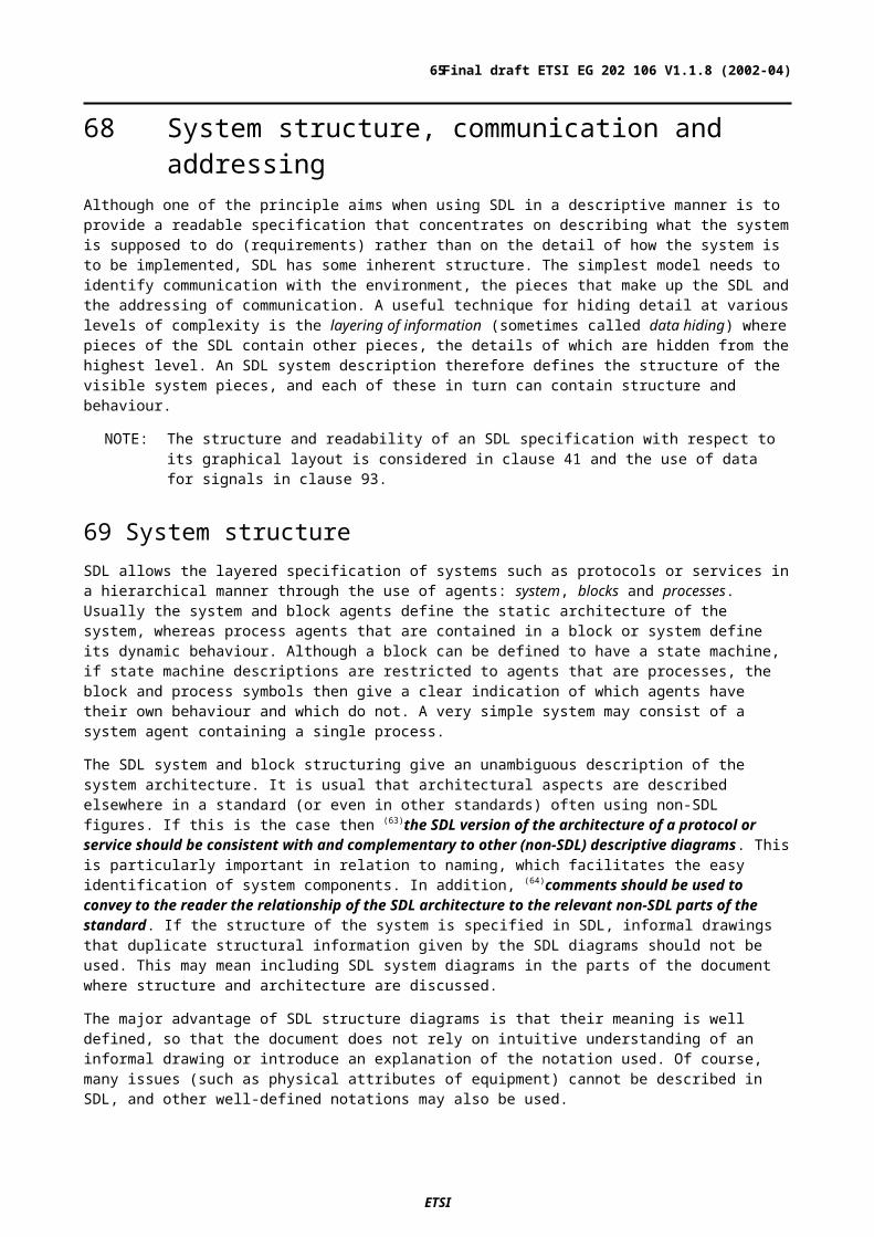
Although SDL supports other forms of communication (remote procedures, import/export and shared data – see clause 89), it is better to use these only in exceptional cases, for example using remote procedures may reduce complex internal signal interchanges. These constructs imply that the calling process waits and passes control to the called process. Such a mechanism cannot be supported easily across a normative interface. (75)Remote procedures, import/export, or shared data should not be used to exchange information between blocks and processes.
80 Use of INTERFACE and SIGNALLIST definitionsUsually there are too many signal names for them all to be listed with a channel or gate, and as well as grouping related signals together in an INTERFACE definition (see clause 74), the interface name can be used to represent the list of signals in several places. For example, in Figure 55 the list OrigToDest is used twice. This can be defined at the system level as:
INTERFACE OrigToDest {SIGNAL SetupReq(SetupType),
ReleaseReq(ReleaseType),DataReq (DataInfo);
USE INTERFACE Failures; }
where Failures is another interface name. The optional INTERFACE keyword before the name clearly identifies that Failures is an interface and not a signal, PROCEDURE or REMOTE variable. A signal list definition could be used instead to define such a list, but without the advantages of an interface definition. For example:
SIGNAL SetupReq(SetupType),ReleaseReq(ReleaseType),DataReq (DataInfo);
/* Note: thses SIGNAL definitions could be separate from the SIGNALLIST */SIGNALLIST OrigToDest = SetupReq,
ReleaseReq,DataReq,(failures);
where failures is another signal list - denoted by the parentheses around the name.
To aid readability the number of signal list items on a gate or channel should be minimized. (76)A small number of interface names (preferably one) should be used to identify the signals on a particular channel or gate rather than listing all signals explicitly. The keyword INTERFACE before the interface name would usually be omitted for reasons of economy of space on the diagram. A list of signal names could be used if there are only one or two signals to list.
Communication paths show the links between sending and receiving entities. The list of signals conveyed in each direction is associated with the direction arrow on the path. These lists are optional if they can be derived from other information but, for clarity, (77)all channels and gates should be shown with the associated interface names, signal list names or signals. This provides the information where the reader needs it.
81 Indicating the use of signals in inputs and outputs A signal instance sent directly from one SDL agent to another will have the same name at both ends of the communication. To indicate the different use of signals in inputs and outputs (for example a Setup considered as a request at the sending side, and as an indication at the receiving side), the following approaches may be used:
1) giving the signal a composite name (for example, SetupReqInd, SetupRespConf);
2) a context dependent suffix attached to the signal name as a comment (see Figure 65).
Figure 65: A comment used as a signal name suffix
ETSI
Final draft ETSI EG 202 106 V1.1.8 (2002-04)65
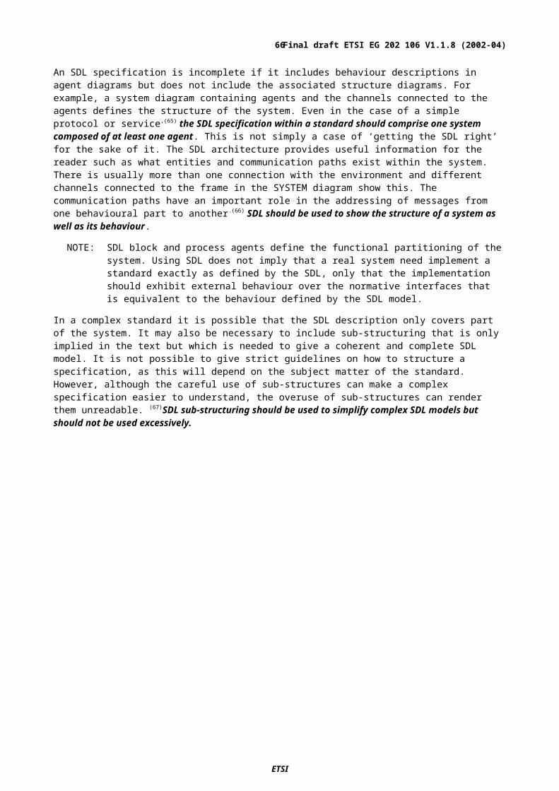
82 Directing messages to the right processSDL allows the specification of a communication path or recipient agent to be part of an output. Although there is often no ambiguity as the signal can only take one path to one consuming agent, adding this information can make it easier to understand the system (see examples in Figure 66). The TO construct can also be used in some cases to identify an agent but, in the example, a comment has been used to clarify that route Clink is connected to a concentrator. The TO construct cannot be used in this particular case because neither is the Pid value known, nor is the process name visible. When there is more than one possible recipient of an output, TO or VIA will be used in order to be unambiguous.(78) TO or VIA should be used in an output symbol to indicate the recipient clearly if this is not obvious from the structure of the SDL system.
When a process sends a signal that it can also receive as an input, it is essential to use TO or VIA to avoid the possibility (unless intentional) that the sending process receives the signal. This situation is common for signals that are "passed on" to another process.
Figure 66: Examples of the use of TO and VIA
SDL also provides a method for directing reply signals using the TO construct and the Pid value of the sender. If the reply is generated before any other signal is received, TO SENDER can be attached to the output statement. If, however, the reply has to be sent after receiving subsequent signals, then the SENDER value needs to be stored in a variable so that it can be used later in an output. It is always safer to use this approach rather than TO SENDER because some SDL constructs (such as remote procedures) implicitly change the SENDER value. Thus for Figure 55, an origination concentrator can reply to either of the destination concentrators by an output such as in Figure 67. For the output Release TO destConcPid to be valid, DestConc has to be the name of an interface, process or process type that handles the Release signal.
Figure 67: Replying to a sender
Where communication is with the environment, any differentiation between entities in the environment should be handled by the identity or content of signals, or the identity of channels, rather than use of the TO mechanism. Interfaces can be defined that correspond to entities in the environment and would be used on the channels leading to the environment.
83 Differentiating messagesThe only way that one message can be distinguished from another before it is received in an input is by its signal name. It is not possible to selectively receive a signal according to its content or the sender or the communication path. When a process reaches a state waiting for a stimulus (a signal or timer), those stimuli that can trigger a transition and those which are saved are distinguished by name only.
NOTE: If a specific signal can be received from several processes, it is not possible to selectively receive it from one source. The sending process identity can be determined by examining the SENDER value, but this does not enable the name of the sending process or block definition to be (easily) determined.
ETSI
Final draft ETSI EG 202 106 V1.1.8 (2002-04)66

To determine the SDL behaviour for each stimulus, it is necessary to define a signal for each distinct event that can lead to a different transition in the SDL. If it is required to distinguish the same stimulus from different sources, then different signal names should be used. (79)A different signal (with a self descriptive name) should be defined for each distinct message event.
Although it is possible to determine the source of a signal from the communication paths leading to the receiving process, (80)the source of the signal in an input should be indicated either by its name or by a comment with the input of the signal because it makes it much easier to understand the description. Figure 68 shows alternative methods for indicating the source of a signal.
Figure 68: Identifying the source of an input signal
It is possible for messages, particularly those coming from the environment, to be defined in a generic form such that it is necessary to examine the message contents to determine what event it represents. In these cases, a process can be used to translate the generic message into signals that have a different name for each event.
84 Multiple outputsMultiple messages output from a single process are sent in the order that the outputs are interpreted. A single output containing several signals is equivalent to outputting each signal in turn as listed (left to right, top to bottom) in the text of the output. (81)There should be only one signal in each output symbol. This makes the description easier to read and clarifies the actual order of the outputs.
85 Transitions triggered by a set of signalsIt is sometimes necessary for a process to trigger a transition only when it has received a set of more than one signal (perhaps from the same entity or perhaps from different entities) although the order in which the signals are received is not important. SDL does not have a built-in mechanism for achieving this but the behaviour can be modelled by saving signals and treating each one in turn.
In the example in Figure 69, the process is waiting for two messages (UserData, DataMode) before entering the DataMode state. The DataMode signal is saved so, if it arrives before UserData, it is not lost and can be processed later. Other signals that can be received are treated in the same way regardless of whether UserData has been received or not.
ETSI
Final draft ETSI EG 202 106 V1.1.8 (2002-04)67

Figure 69: Waiting for multiple messages
86 Gates and implicit channelsIf any gate on a type based agent definition is left unconnected in a diagram, implicit channels are derived to connect the gate to any agents in the diagram and gates or channels connected to the diagram that handle the interface elements of the gate.
If no channel had been drawn between User and Net, there would have been implicit channels joining the otherwise unconnected gates of User and Net to the matching gate on the other block. Implicit channels are created when there are gates (such as the interface gates Calling and Called defined for User in Figure 64 derived from BLOCK TYPE Usertype in Figure 62) which are not connected to channels. Even for this simple example the use of explicit channels to show the communication paths makes it clear what paths exist, and in more complex examples there may be implicit channels that were not intended between unconnected gates.
To avoid undesirable implicit channels,(82) all the gates of an agent should be explicitly connected to channels.
It is allowed to have gates on an agent definition that is not type based. Such gates are shown as gate symbols on the outside of the block or process symbol that references the agent diagram (similar to the interface gates Calling and Called on BLOCK TYPE Usertype in Figure 62)., but for the reasons explained above all gates should be connected to channels but this is not allowed for such gates shown outside agents. To avoid these undesirable implicit channels,(83) gates should not be attached to block symbols or process symbols.
87 Other structuring mechanismsIn most blocks the contained agents (usually processes) define the behaviour of a block, and a block does not usually have a state machine of its own. By comparison most processes just contain a state machine description and do not contain any other agents. This keeps the structure relatively simple and easy to understand. All the state machines in such simple systems belong to processes and potentially have parallel concurrent behaviour: that is each process instance can potentially have its own processor (though in a real implementation there would be less – perhaps only one). It is not required that each process instance actually has its own processor, only that the system behaves as if this is the case.
Other structuring mechanisms exist in SDL, but make the model more complex.
88 Processes within a processA process is allowed to contain other processes (but not blocks). Each contained process instance has its own state machine and input queue, but all the state machines share one processing resource so that only one process instance is
ETSI
Final draft ETSI EG 202 106 V1.1.8 (2002-04)68

scheduled at any one time: only one process instance can be interpreting a transition. When this process instance reaches a state, one of the process instances that can enter a transition (if any) is scheduled. If there is no process instance ready, all of the process instances wait until one is ready. Such a structure more accurately models running processes on a single processor. The starting and stopping and other co-ordinating actions of the processes can be more complex. In general, (84)process definitions contained within process definitions should be avoided, unless the intention is to exclude concurrent interpretation of processes. The diagram of a process (type) with contained processes is identical to a block (type - respectively) with contained processes except for the keyword PROCESS instead of BLOCK in the diagram heading.
Figure 70: A process with contained processes.
89 Shared dataAny agent can contain data variables even if contains other agents and no explicit state machine. The contained agents can access these variables. If the containing agent is a block, there is an implicit state machine for the block that owns these variables, and access to the variables is by implicit remote procedure calls. If the containing agent is a process, the contained processes are scheduled one at a time (as described above) and access the data directly.
The use of such data may be a convenient way to represent a common database that is accessed by different parts of the model. In most cases an agent that encapsulates the data would probably better model this, so that it is clear what communication is really taking place. In any case, shared data should not be used to pass information between agents that otherwise communicate via a normative interface. (85)The use of shared data should be avoided.
90 Hiding and re-using parts of a stateIn more complex systems where a large number of different signals can be received in each state, the behaviour may be difficult to understand even after introducing multiple occurrences of the state on different pages of the diagram. In these cases, it may be acceptable to hide the consumption of some of the less important parts of the behaviour in a state diagram, so that input of some signals is hidden from the agent level. Hiding some sub states in this way can, in some instances, be better than using a procedure diagram because signals that cause exit from the state are shown with the state in the agent diagram.
Use of a composite state (one with behaviour in a STATE or STATE TYPE diagram) to hide distracting detail can make the overall behaviour of agent easier to understand. A composite state is appropriate if the agent is considered to be in a "global state" (such as establishing a call), but actually needs different states related to the detailed handling of some of the signals received. In Figure 71 the state CallinMonitor is based on the STATE TYPE Monitor in Figure 72 that gives more detail for the state, in this case to receive two signals before proceeding to the Data state.
A state that has an associated diagram (a composite state) can be recognized by an exit line that goes directly to a transition or another state. It is not always easy to see if a state is basic or a composite because:
- the symbol is the same in each case;
- there can be multiple occurrences;
- the exit line may not be obvious and there need not be an exit line.
In particular, if a STATE diagram (rather than a STATE TYPE) is used, this has the same name as in the state symbol, which therefore looks like a basic state. Unlike other diagrams, no specific reference symbol exists for STATE diagrams.
ETSI
Final draft ETSI EG 202 106 V1.1.8 (2002-04)69
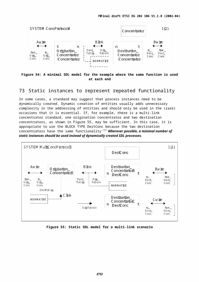
If, however, a composite state is based on a STATE TYPE, it is clear the state symbol contains a composite state because a colon and the STATE TYPE identity follow the state name. Also a STATE TYPE diagram must have a separate reference from the diagram in which it is defined, such as the reference to Monitor in the state type symbol in Figure 71. For these reasons (86)a composite state should (87)use a STATE TYPE diagram rather than a STATE diagram.
Figure 71: A state that references a STATE TYPE
Figure 72: A STATE TYPE diagram
Another advantage of using a STATE TYPE, rather than a STATE diagram, is that a STATE TYPE can be used in several places. Monitor could be used with state Audio as in Figure 73. Other inputs from Audio are defined elsewhere.
ETSI
Final draft ETSI EG 202 106 V1.1.8 (2002-04)70

Figure 73: Re-use of the STATE TYPE used in Figure 71
91 Using packagesWhen ASN.1 is included into SDL, the ASN.1 is treated as a package referenced from the SDL. Other packages that define commonly used behaviour could also be included. In both these cases, the SDL is made simpler by not having to repeat the contents of the package. Some dangers of using an external package are, firstly, that it may not be clear exactly what the package does and, secondly, that it may not be obvious that the contents of the package may be changed.
The main advantage of packages is the possibility of re-use, which for standards is less likely than for product engineering. In a standards context it is often better to have as most of the definition within the standard itself and packages (other than for ASN.1) would not normally be needed.
92 Exception handlingExceptions provide a mechanism for handling situations that are possible but unusual or undesirable. Exception handling tends to be more difficult to understand than control that depends on decisions, because a search has to be made (both by a reader and during interpretation) for the exception handler apart from the normal control flow. The advantage of exception handler is that normal flow can be more concise as the abnormal situations can be handled in one place.
(88)A standard should be defined so that the language-defined exceptions (such as OutOfRange) do not occur. In most cases this can be achieved by explicit checks.
93 Specification and use of dataA very important part of any protocol or service standard is the specification of data. SDL has its own built-in data types and mechanisms to create new data types. However, the standardized data type notation, ASN.1 (see ITU-T Recommendation X.680 series [8, 9, 10, 11], is usually used in modern telecommunications standards to specify messages and other data, particularly for normative interfaces. ASN.1 data types may be used as an alternative to SDL data types by making these available to the SDL through ASN.1 modules used as packages (see ITU-T Recommendation Z.105 [5]).
NOTE: Strictly speaking SDL data types are called 'sorts'. However, in the present document for the sake of simplicity the term 'data type' is used both in the context of using ASN.1 and SDL sorts.
An advantage of using ASN.1 is that the ASN.1 data types can be associated with encoding rules, whereas there is currently no standardized way of associating encoding rules with SDL data types.
(89)ASN.1 should be used to specify data and the ASN.1 data definitions should be made common to both the SDL specification and the non-SDL parts of a standard.
This approach of common data has the significant advantage of reducing the possibility of confusion and mistakes that can be introduced if there are separate data descriptions of the same or similar data structures.
There are no operators in ASN.1. However, when ASN.1 is used with SDL, the basic types of ASN.1 (such as INTEGER) are mapped to the corresponding SDL types (in this case Integer) and therefore the predefined SDL operators can be used with these types. Similarly an ASN.1 SEQUENCE (or SET) is taken to be an SDL STRUCT, an ASN.1 CHOICE an SDL CHOICE, and a SEQUENCE OF (or SET OF) an SDL String. Table 2 shows the mapping between some ASN.1 and SDL.
ETSI
Final draft ETSI EG 202 106 V1.1.8 (2002-04)71

Table 2: Some ASN.1 types and corresponding SDL data types
ASN1 SDLBIT Bit
BIT STRING BitstringBOOLEAN BooleanCHOICE CHOICE
OCTET STRING OctetstringSEQUENCE STRUCT
SEQUENCE OF StringSET STRUCT
SET OF Bag
94 Specifying messagesOne of the main purposes of using SDL in an ETSI standard is to provide an unambiguous description of the exchange of messages over normative interfaces.(90) SDL signals should be used to represent normative messages with ASN.1 describing the parameters carried by the messages. The behaviour diagrams of SDL agents describe dynamic mechanisms that control the sending and receiving of these messages.
NOTE: The details of these dynamic mechanisms are not usually normative and the SDL that describes them should be regarded as just one description of any number of possible alternative descriptions. What is normative is the behaviour that the combined SDL state machines exhibits over the normative interfaces with regard to message interactions.
Even though an ASN.1 module will specify the complete set of messages and message parameters relevant to a standard, it is unlikely that all the message parameters will be directly relevant to the SDL model. Note that even if the ASN.1 data type definitions are complex, only those parameters relevant to the dynamic requirements of the standard need actually be used in the SDL behaviour descriptions. In this way, the complexity of the data type definitions does not adversely affect the readability of the SDL specification
95 Structuring messagesExcept in the very simplest of cases, (91)the top-level parameters of messages should be contained in a single structured type (e.g., ASN.1 SEQUENCE or SET) rather than specified as a list of simple types.
For example, the longer but considerably more meaningful specification in a) below, is preferable to the more open simple signal specification in case b). Although a) could be completely expressed in SDL (using STRUCT and Bitstring with SIZE), ASN.1 is used as this the preferred notation. In b) no ASN.1 is necessary because the SIGNAL is defined just in terms of Bitstring mapped from the ASN.1 data type BIT STRING.
ETSI
Final draft ETSI EG 202 106 V1.1.8 (2002-04)72

a)
SIGNAL SETUP(SETUPtype); /*in SDL */
-- in an ASN.1 module used as a PACKAGE by the SDLSETUPtype ::= SEQUENCE { header Header, -- Note that these examples follow the ASN.1 convention of
identifier Identifier, -- starting identifiers with lower case letters and starting extensionBlock ExtensionBlock -- type references with upper case letters.
}
Header ::= BIT STRING (SIZE (8..32))
Identifier ::= BIT STRING (SIZE (8..8))
ExtensionBlock ::= SEQUENCE { callReference CallReference,
partyReference PartyReference }
CallReference ::= BIT STRING (SIZE (4..8))
PartyReference ::= BIT STRING (SIZE (4..8))
callref15 BIT STRING ::= '00001111'B
b)
/* in SDL */ SIGNAL SETUP (Bitstring, Bitstring, Bitstring, Bitstring);
/* NOTE that BIT STRING in ASN.1 is mapped to Bitstring in SDL */
When compared with item b), the ASN.1 in item a) has the benefit of being able to give explicit names to message parameters in the SDL signal. It uses SIZE restrictions in a readable manner. Finally, an advantage of using ASN.1 in this example is that the ASN.1 data types, the user defined SETUP and the pre-defined BIT STRING, can be associated with encoding rules.
The use of structures has the added benefit of allowing the easy capture and manipulation of the entire contents of messages rather than on a parameter-by-parameter basis. Figure 74 shows how the contents of an incoming message can be simply output on another channel. In this example, setupOut has been declared as a variable of a structured type (see below).
Figure 74: Transferring message contents from Input to Output
A minor drawback of using complex structures is that the notation to refer to the elements in the SDL description may be longer. For example, if two variables, setupExtensionblock and setupOut were declared as follows:
DCL setupExtensionblock ExtensionBlock;DCL setupOut SETUPtype;
an assignment to store the ExtensionBlock value would be:
setupExtensionBlock:= setupOut.extensionBlock
ETSI
Final draft ETSI EG 202 106 V1.1.8 (2002-04)73

and an assignment in the SDL to the callReference to output callref15 would be:
setupOut.extensionBlock.callReference:= callref15
Clause 52 gives details of how operators can be used to hide long references. It also shows how operators may be added to ASN.1 types.
In the above example a full stop (.), was used to denote field selection. SDL also allows an exclamation mark (!) to be used with the same meaning. Using an exclamation mark makes it clear that field is being selected rather than a method applied to the variable, whereas the dot notation is normal for both cases in many other languages. (92)For readability the same symbol (exclamation mark or full stop) should be used for all field selections in one specification.
96 Ordering message parametersProtocol messages are most easily specified using the ASN.1 constructors, SEQUENCE or SET. (93)If the parameters in a message have to appear in a fixed order, then the ASN.1 constructor SEQUENCE should be used to specify the message contents, as in the following:
SETUPin ::= SEQUENCE{ header Header,
identifier Identifier,inExtensionBlock InExtensionBlock
}
However, it is common that a protocol specification will allow elements to appear in any order. (94)If the parameters of a message may appear in any order, then the ASN.1 constructor SET should be used to specify the message contents. For example, in the extension block of the previous example it could be required that it is possible to receive the callReference and the partyReference in either order, in which case this would be specified as follows:
InExtensionBlock ::= SET{ callReference CallReference,
partyReference PartyReference}
NOTE 1: In ITU-T Recommendation Z.105 [5] SET and SEQUENCE are treated in the same way in SDL, and therefore parameters are required to be in a specific order in SDL.
Another useful concept in ASN.1 is the ability to specify parameters as OPTIONAL. In the following example the partyreference may be omitted
ExtensionBlock ::= SET{ callReference [1] CallReference,
partyReference [2] PartyReference OPTIONAL}
Finally, ASN.1, allows the specification of unions through the CHOICE construct, for example:
GeneralMessage := CHOICE{ setup SETUPtype,
release RELEASEtype,acknowledge ACKNOWLEDGEtype
}
NOTE 2: Tags ([1] and [2]) have been introduced in the SET ExtensionBlock to enable encoders to differentiate between the two parameters, but are otherwise ignored in SDL models. Alternatively automatic tagging could be used, as is assumed in the CHOICE GeneralMessage.
ETSI
Final draft ETSI EG 202 106 V1.1.8 (2002-04)74
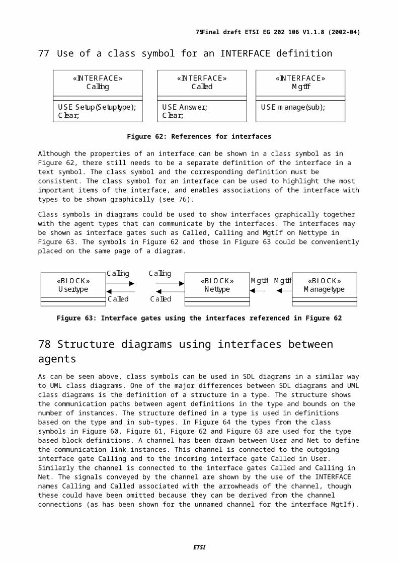
97 Transposing other message formatsIn many lower-layer protocol standards, messages are specified using a tabular format. These tables will have to be transposed to ASN.1 or SDL data types in order to be used in an SDL specification. In these cases it will probably be adequate to specify a simplified form of the messages (e.g., by omitting various message parameters).(95) When mapping messages described in another format (such as tables) to a simplified form as ASN.1 or SDL data types, the structure of the simplified messages should be kept as close as possible to the structure of the original messages and the names of messages and their associated parameters should be preserved. The important point is that messages should be reduced to a simpler format in a consistent manner and that the mapping from the real messages to the simplified ones in the SDL is well documented and obvious. Conversely, parameters that are not specified in the full description of the messages should not be introduced in the transposed formal specification.
98 Specifying data that is internal to the SDL modelData that is internal to the SDL model is data that is not conveyed over a normative interface. Such internal data may be specified using either SDL types or ASN.1. In most cases it will be simpler to use SDL data types. SDL directly supports the same features as ASN.1 such as SIZE, OPTIONAL and CHOICE.
The main benefit of specifying the data in SDL is that the data type can be directly embedded in the SDL diagrams, whereas ASN.1 data types have to be included by a USE package clause that refers to ASN.1 modules containing the data type definitions.
While the mappings provide basic operators for using ASN.1 types in SDL, data type specific operations can only be added to an inherited type or some (otherwise unrelated) type. (96)When there are data type specific operations for internal data, it is usually better to use SDL to define the data type rather than ASN.1 so that the operations can be defined as part of the data type.
A minor disadvantage of ASN.1 (compared with SDL data types) is that if one ASN.1 type is defined as based on another type, the values defined on either type are values of both types: the types are equivalent. In SDL the user can choose to introduce either another name (as in ASN.1), or a new data type that inherits the same properties but is distinct from the original. When such a new type is introduced, items of one type cannot be used (by mistake) where the other type has been specified. This feature is generally known as "strong type checking".
SDL has two predefined array constructor data types, ARRAY and VECTOR. These do not have a direct correspondence to data types in ASN.1 and it may be simpler to use these predefined data types rather than define types in ASN.1. It may also be simpler to define some data types directly in SDL using the predefined STRING constructor data type. In all these cases variables and values of the constructed data type can be indexed to select an array, vector or string element. Indexing of ARRAY, VECTOR and STRING constructs is denoted by the index expression in square or round brackets after the variable (or value). (97)For readability, in one SDL specification the same brackets (square – which are distinct from other uses, or round) should be used for all ARRAY, VECTOR and STRING indexing.
99 Use of symbolic namesClauses 59 and 62 recommend that SYNONYM definitions or enumerated types should be used to specify symbolic names that can be used as decision labels and that convey meaningful information to the user. When the data type is specified in ASN.1, an ASN.1 value definition can be used instead of an SDL SYNONYM definition. For example, in an ASN.1 module
maxNumberLength INTEGER ::= 20
is equivalent to the SDL SYNONYM definition
SYNONYM maxNumberLength INTEGER = 20;
The use of the symbolic name maxNumberLength for the value both makes the description more understandable and allows the actual value to be specified in one place only. In this way, the value can be simply changed by changing the definition and all uses (in expressions, parameters, data type definitions, size constraints, decisions and so on) will then use the updated value. (98)Whenever possible symbolic names should be used rather than explicit value denotations (such as 123, '0110'B). Either an ASN.1 value definition or an SDL SYNONYM can be used to define a symbolic name. The explicit data value should appear just once: in the definition the symbolic name.
ETSI
Final draft ETSI EG 202 106 V1.1.8 (2002-04)75

It is often the case that there are a limited number of values for a particular data type, and although the actual transmitted encoding may be important, in the specification of the behaviour it is only necessary to compare one value with another and there is no need for other operations such as arithmetic on the values. The appropriate data type is an enumerated type to introduce symbolic literal names for the values. Both ASN.1 and SDL allow an Integer value to be associated with the literal. For example:
LineState ::= ENUMERATED { outOfService (1),
inServiceFree (2), inServiceBusy (6) }
is equivalent to the SDL:
VALUE TYPE LineState;LITERALS
outOfService = 1,inServiceFree = 2,inServiceBusy = 6;
ENDVALUE TYPE LineState;
Wherever possible (99)ASN.1 ENUMERATED or SDL literal list types should be used for data that consists of a collection of names. Numeric values should be associated with the values of a data type by using the named numbers of an ASN.1 ENUMERATED or SDL literal list type.
If it is not possible to use a data type to define symbolic names for values, the name can be defined as an ASN.1 value definition or SDL SYNONYM.
100 Using data TYPE and SYNTYPEThe VALUE TYPE (or OBJECT TYPE see 101) syntax can be used to specify an application data type in SDL. A data type defined as a VALUE TYPE has variables that are associated with values of the type: the predefined types (Integer, Boolean etc.) are defined using VALUE TYPE.
An SDL data type has a set of values and a set of operations that can be inherited by another data type. An operation can be an OPERATOR, which does not modify any of its parameters but can return a result, or a METHOD, which is applied to a variable and can modify this variable.
SYNTYPE defines a range of another data type. Typically the range defines a subset of the values of the parent data type, for example:
SYNTYPEInt16 = Integer CONSTANTS ( 0..65535 );
ENDSYNTYPE;
The range can include all values of the parent data type, in which case the SYNTYPE is particularly suitable for renaming existing types, for example:
SYNTYPEDestPointCode = Int16;
ENDSYNTYPE;
A SYNTYPE that does not define a subset of the values of the parent data type, can be used to rename a data type to an alternative name.
VALUE TYPE, on the other hand, is more suitable for specifying new data. In general (100)VALUE TYPE should be used to define a new data type in a specification while SYNTYPE should by used to rename or constrain the values of existing data types.
It is worth noting that the following ASN.1 specification:
Btype::= Atype
is equivalent to the SDL:
SYNTYPE Btype = AtypeENDSYNTYPE Btype;
These data types have compatible values. An Atype value can be assigned to a Btype variable or vice versa.
ETSI
Final draft ETSI EG 202 106 V1.1.8 (2002-04)76
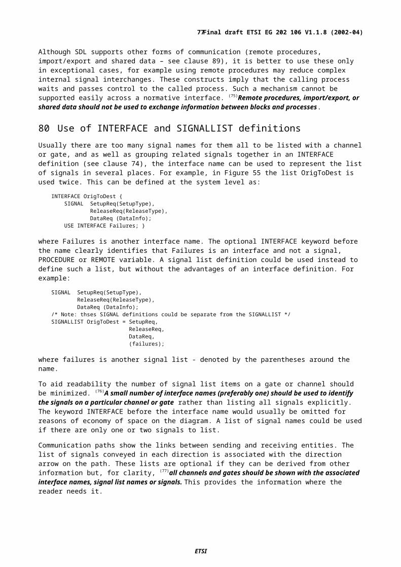
101 Using OBJECT TYPEWhen a data type is defined as an OBJECT TYPE, a variable of that data type is associated with references to values. In the following, such a variable is called an object variable.
When a value is assigned to an object variable, an object is created that contains the value. When an object is assigned to an object variable, the variable then references the object, so that it is possible for two object variables to reference the same object. Therefore OBJECT TYPE data is more suited to the data structures that will be created dynamically with elements linked by the reference characteristics of objects: for example linked lists, or trees.
OBJECT TYPE parameters of signals are either converted to values or require a common container process. When such a signal is used in an output in a PROCESS TYPE whether the parameter is passed as a value or an object will depend on the context of process definitions based on that type. If the object is passed, two processes could refer to the same object and there is the possibility of multiple processes changing the same object. If a value is passed then there is little benefit in having an object parameter. For these reasons (101)OBJECT TYPE should be avoided as the data type for signal parameters.
A data type that is defined as a VALUE TYPE can be used as an OBJECT data type by prefixing the data type name with the keyword OBJECT and therefore defines an OBJECT TYPE. Similarly an OBJECT TYPE can be used as a VALUE TYPE by prefixing a data type name with VALUE.
When inheritance is used with OBJECT TYPE definitions, one result is that some operations using the data types involved are "polymorphic", which means the actual operation to be applied depends on what happens when the system is interpreted. Because the polymorphic character of OBJECT TYPE definitions can make the use of the data difficult to understand, (102)OBJECT TYPE definitions(or a data type name prefixed by OBJECT) should be used only when the data cannot be simply expressed with a VALUE TYPE.
All data types inherit some properties from the Any data type, an OBJECT TYPE that is a root type for all data. Use of the (103)Any data type to define variables should be avoided, because the resulting behaviour may be difficult to understand and may have dynamic errors.
102 Using Message Sequence Charts (MSC)
103IntroductionThe Message Sequence Charts (MSC) language is defined in ITU-T Recommendation Z.120.
A basic MSC describes a scenario and consists of interacting instances. An instance is an object that has the properties of a certain entity. On an instance, the ordering of events is specified. Events can be message outputs, message inputs, local actions and timer events.
An HMSC (High-level Message Sequence Chart) is a roadmap of scenarios, where the details are hidden and described in basic MSCs or HMSCs that are referenced in the HMSC.
104Relationship between MSC and SDLAs far as possible, entities in MSC should correspond to SDL entities. Normally, it is only useful to specify a subset of a system's behaviour in MSC. It is also common not to reproduce the complete SDL architecture in MSC, but to represent only the important communicating parts with MSC instances.
In the ITU MSC recommendation, the interpretation of a message input is not described. (104)When MSC is used in combination with SDL, a message input in MSC should correspond to a signal consumption in SDL.
ETSI
Final draft ETSI EG 202 106 V1.1.8 (2002-04)77
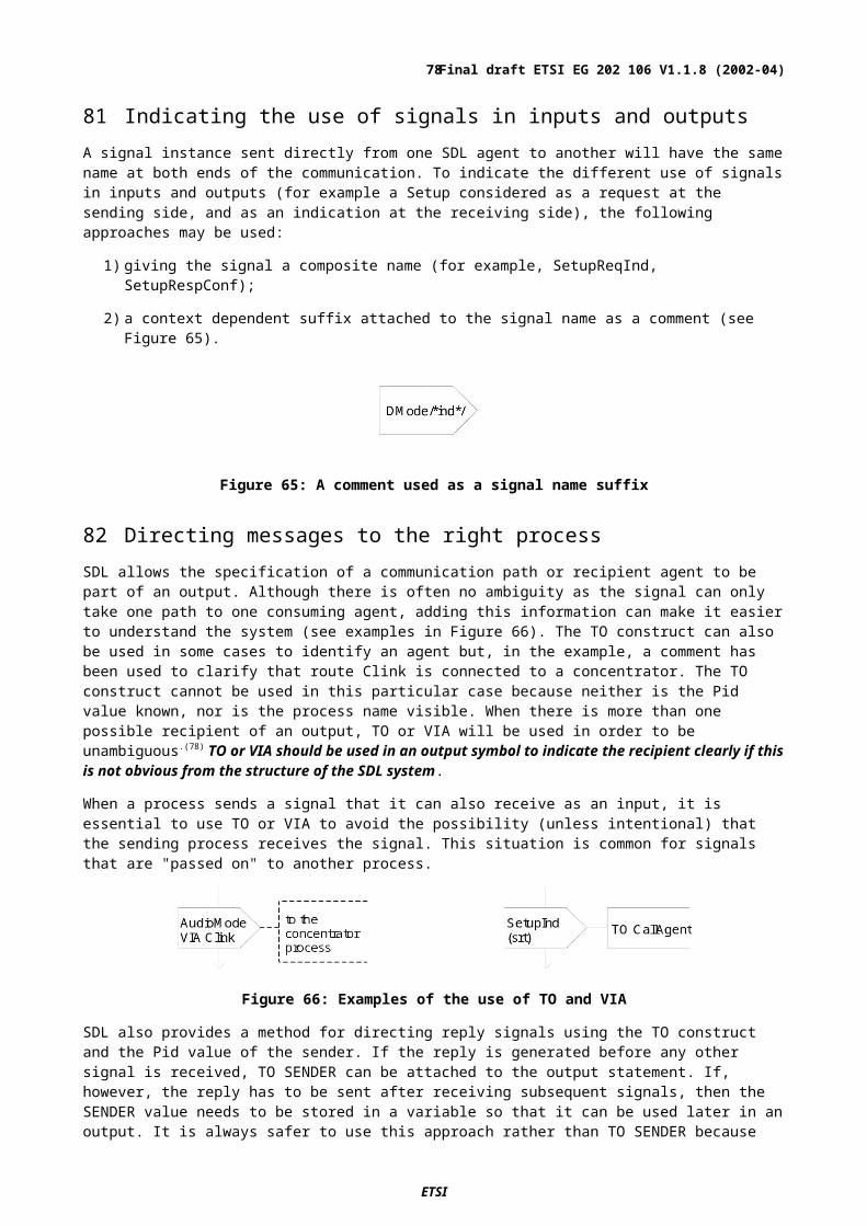
105Presentation and layoutThere should be a reasonable amount of information in an MSC diagram, making the specification easy to comprehend but (105)each MSC diagram should be limited to the information that fits into one printed page. Additionally, (106)when used in a standard, an MSC diagram should always be surrounded by a diagram frame and have an attached name.
The structuring mechanisms in MSC can be used to avoid large diagrams. If splitting a scenario into several distinct MSC diagrams is not feasible, vertical paging of diagrams can be used. If vertical paging is necessary, the instance heads and the MSC diagram name should be repeated on each page. The instance end symbols must only appear on the last page. However, horizontal paging should be avoided.
(107)A clear spacing between symbols in an MSC diagram should be maintained both horizontally and vertically. This makes it easier for each instance and message to be clearly distinguished from any others.
(108)An instance axis should always be terminated at the end by either an instance end symbol or a stop. If vertical paging is used, an unterminated instance axis indicates that the diagram continues on another page.
106 AnnotationsThere are four different annotations in MSC:
note
-appears between items of texts;
comment symbol
-can be attached to events or symbols;
text symbol
-may contain larger texts for documentary purposes;
informal action
-may be used to informally express internal behaviour of an instance (see also 123).
As in any formal language, (109)annotations help to improve the understanding of an MSC description and should be used freely.
Another very useful practice is to annotate which scenarios (or parts of scenarios) that are normal from those that are exceptional.
ETSI
Final draft ETSI EG 202 106 V1.1.8 (2002-04)78
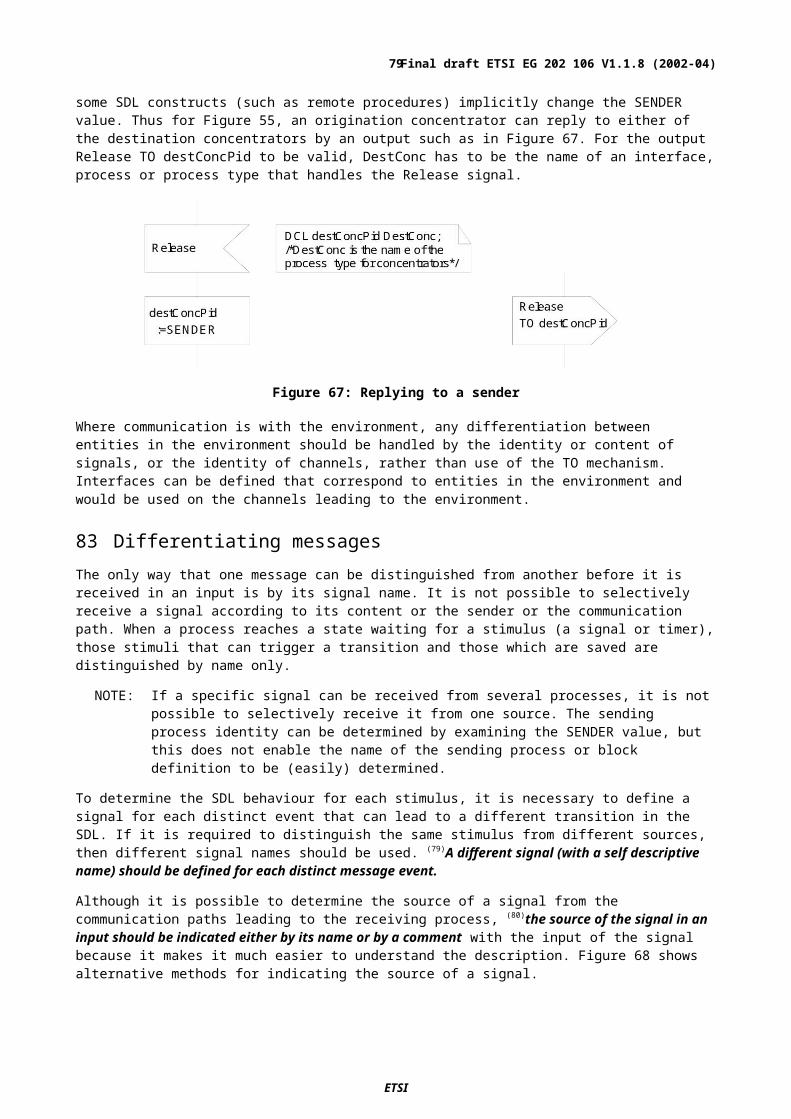
Figure 75: Annotations in MSC
107Naming and scopeMost MSC names are globally visible within the set of MSC and HMSC diagrams defined by one MSC document specification. An instance kind name is visible outside of its MSC document. Gate names and MSC formal parameter names are visible in the scope of one MSC diagram.
As far as possible, (110)names in an MSC should be the same as the names of corresponding entities in the SDL. For example, an MSC message name should be the same as its corresponding SDL signal name, and an MSC instance should have the same kind name as the corresponding SDL process or block.
An entity may have the same name as another visible entity if the two entities are of different classes. A message may thus have the same name as a timer or an instance. (111)Entity names should be unique within a specification.
108MSC documentAn MSC document is a collection of MSCs and HMSCs (Figure 76), declaring used instances, messages, timers and MSC References. It is also the defining document for an instance kind. An MSC document might specify an inheritance relationship between two instances (instance kinds), allowing specialization of used scenarios (MSC References).
Since an MSC document is not needed unless instance decomposition, instance kind inheritance or the data concepts are used, it can often be omitted in order to reduce complexity of the specification.
ETSI
Final draft ETSI EG 202 106 V1.1.8 (2002-04)79
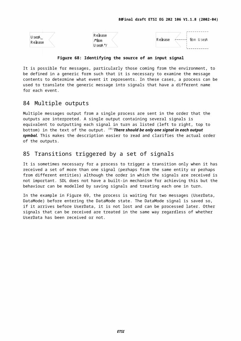
Figure 76: Collection of MSC diagrams
109StructuringThere are two distinctive mechanisms for structuring MSC specifications. The first is related to the logical system architecture. The second is related to behaviour.
110 Architecture
111 Instance
An instance is an object of an entity specifying behaviour by means of events that are ordered on the instance axis. More than one instance might be used to describe one entity. Every instance has a name associated with it and an optional kind name, e.g. process name, which indicates which entity the instance is describing. In relation to SDL, the kind name can be preceded by a kind denominator which mat be one of the reserved words system, block or process. An instance without kind name will have its own name as an implicit kind name. (112)If there is an associated SDL specification, each MSC instance should have a kind name and kind denominator corresponding to the name and entity kind of the equivalent entity in SDL.
It is easy to add more and more instances to an MSC in an attempt to make it easier to understand. Unfortunately, this can have the opposite effect by adding complexity which can be an unnecessary distraction. So, (113)the number of instances included in an MSC should be kept low to maintain a focus on the normative interface(s) and important entities in the logical or physical model.
The instance name (together with the optional kind name) may be placed above or inside the instance head. For the sake of consistency, (114)if the kind name is present in an MSC instance, the instance head symbol should contain the instance name with the kind name placed above the symbol, as shown in Figure 77. Otherwise both names have to be separated by a colon symbol.
ETSI
Final draft ETSI EG 202 106 V1.1.8 (2002-04)80
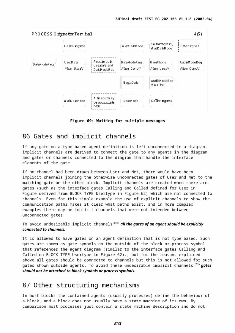
Figure 77: Placement of instance name and kind name
112 Instance decomposition
Behaviour described by several instances can be composed into one instance, hiding the intra-communication between the original instances. This means that the same part of a scenario is described in (at least) two diagrams, firstly on the higher level and secondly on a lower level, showing the internal behaviour of the decomposed instance. Furthermore, a decomposed instance needs a defining MSC document in which used instances, messages and MSC References are defined. (115)Instance decomposition should be avoided in MSCs because of the complexity it might introduce.
It is however good practice to represent a higher-level SDL entity with an instance, without describing the lower-level behaviour, if this abstraction improves the understanding of the overall behaviour.
113 Dynamic instances
Dynamic instances in MSC can be described by using the instance creation and instance stop concepts. Generally, standards describe a static view of the components avoiding the more complex dynamic identity relations and so (116)dynamic instances should be avoided in MSCs. Instance creation and instance stop should only be shown if they are a vital part of the specification.
Note the difference between the instance end and the instance stop. The instance end terminates the description of the behaviour of an instance within one MSC diagram, while the instance stop describes the termination of the entity that the instance represents.
114 Environment
In general, one MSC specifies the possible behaviour of only a part of a certain system. Everything else is referred to as "the environment" with which messages can be interchanged. The environment can be considered to be one or several instances that communicate with the instances in the MSC. Graphically the environment is represented by the diagram frame. Communication with the environment is provided by message arrows connected to the frame (see Figure 78).
Figure 78: Messages being sent to and from the environment
ETSI
Final draft ETSI EG 202 106 V1.1.8 (2002-04)81
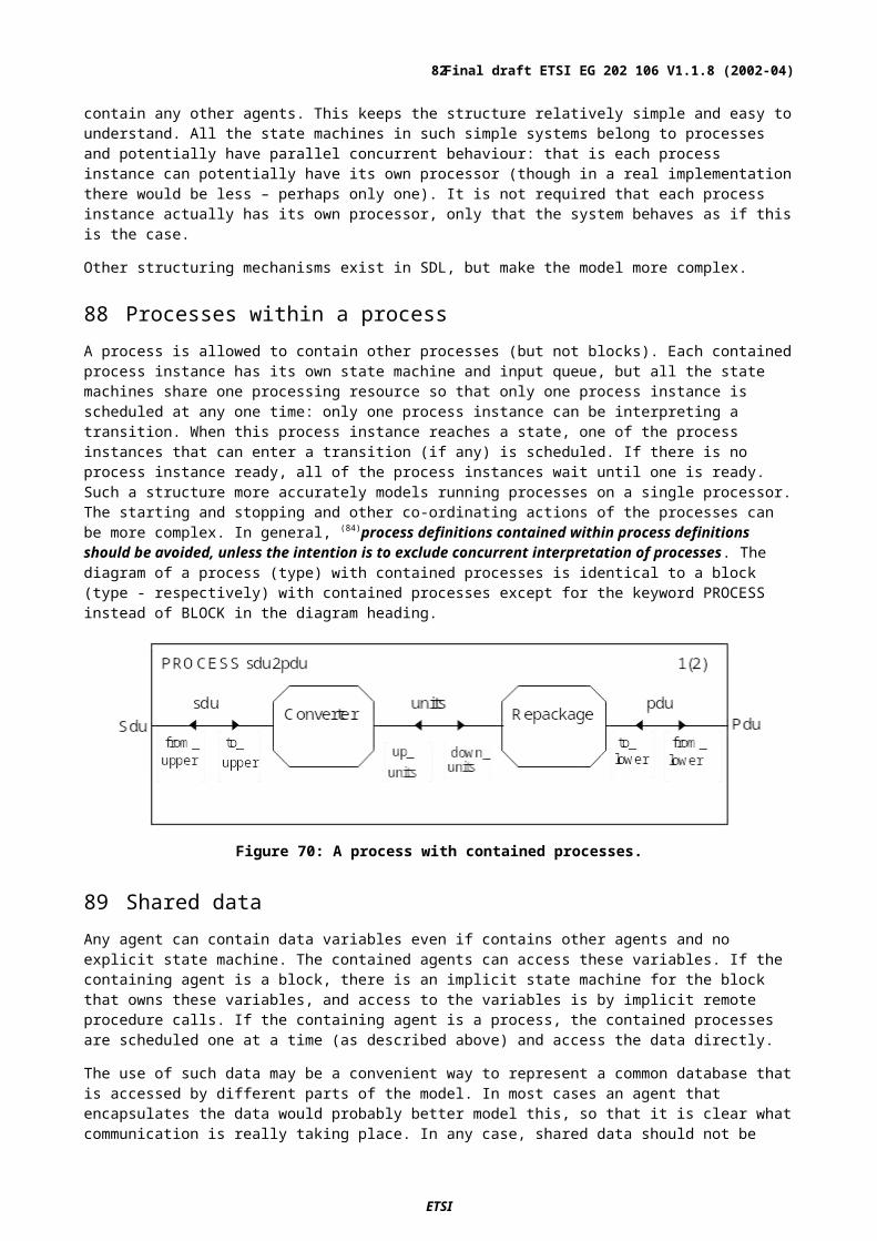
There are situations when using the frame to represent the environment is counter-intuitive. In the example shown in Figure 78, a natural, but not justified interpretation would be that the message CallAlerting is sent in response to message IncomingCall. In fact, message CallAlerting might be sent before message IncomingCall, possibly from a different entity than the receiver of message IncomingCall.
As an alternative to the environment frame, specific instances may be used to describe the interaction of the system with the environment. When there is communication with more than one distinct environment entity, explicit instances for the environment enable the description of ordering. and allow a concrete behaviour description of external entities that interact with the system under consideration. (117)Instances with instance kind name "environment" should be used to represent the environment in an MSC.
Figure 79: MSC with instances representing the environment
115 BehaviourIn MSC, there is a possibility to divide complex scenarios into smaller, named descriptions. There are several reasons to do this:
making the specification easily readable and suitable for print-out;
reuse of common behaviour parts, ensuring easier maintenance of the specification;
hiding details while focussing on message exchange;
keeping logically distinct parts separate.
This structuring of behaviour is realized by allowing expressions on MSC parts. The parts can be a group of events or an MSC Reference. In an expression, the following relationships between the parts might be expressed:
sequence (seq);
alternative (alt);
optionality (opt);
repetition (loop);
parallelism (par);
exception (exc).
These expressions might be used in three different ways or contexts:
HMSC;
MSC references in basic MSCs;
ETSI
Final draft ETSI EG 202 106 V1.1.8 (2002-04)82

In-line expressions in basic MSCs.
An MSC Reference is used to refer to other MSC or HMSC diagrams by means of their MSC name. MSC References may be used within basic MSCs or in HMSCs.
Generally, unrestricted use of the expressions can cause an explosion of the number of scenarios, which may cause problems with validation.
116 High-level MSC (HMSC)
The composition of a set MSCs is specified by means of a High-level MSC (HMSC) which is a roadmap of the contained MSC References. HMSCs provide a graphical way of describing the combination of Message Sequence Charts, typically visualizing sequence, alternative and loop relationships.
(118)HMSCs should be used to specify a high-level view of scenarios which are defined in other MSC or HMSC diagrams.
Apart from MSC References, an HMSC can also contain conditions, start, stop and connection symbols.
(119)Connections should always be used when HMSC flow lines join or merge to distinguish them from simple crossing lines.
Unlike plain MSCs, instances and messages are not shown within HMSCs, which focus only on composition aspects.
Figure 80: Example of HMSC usage
The annotations, "Token based security" and "No token support available" help to provide some helpful functional segregation within the HMSC shown in Figure 80. Such (120)annotations should be used within HMSC to explain the purpose of different alternative branches.
HMSCs are hierarchical in the sense that an MSC Reference may refer to an HMSC and, consequently support a top down design approach very well. In order to maintain sufficient transparency and manageability, (121)References to
ETSI
Final draft ETSI EG 202 106 V1.1.8 (2002-04)83
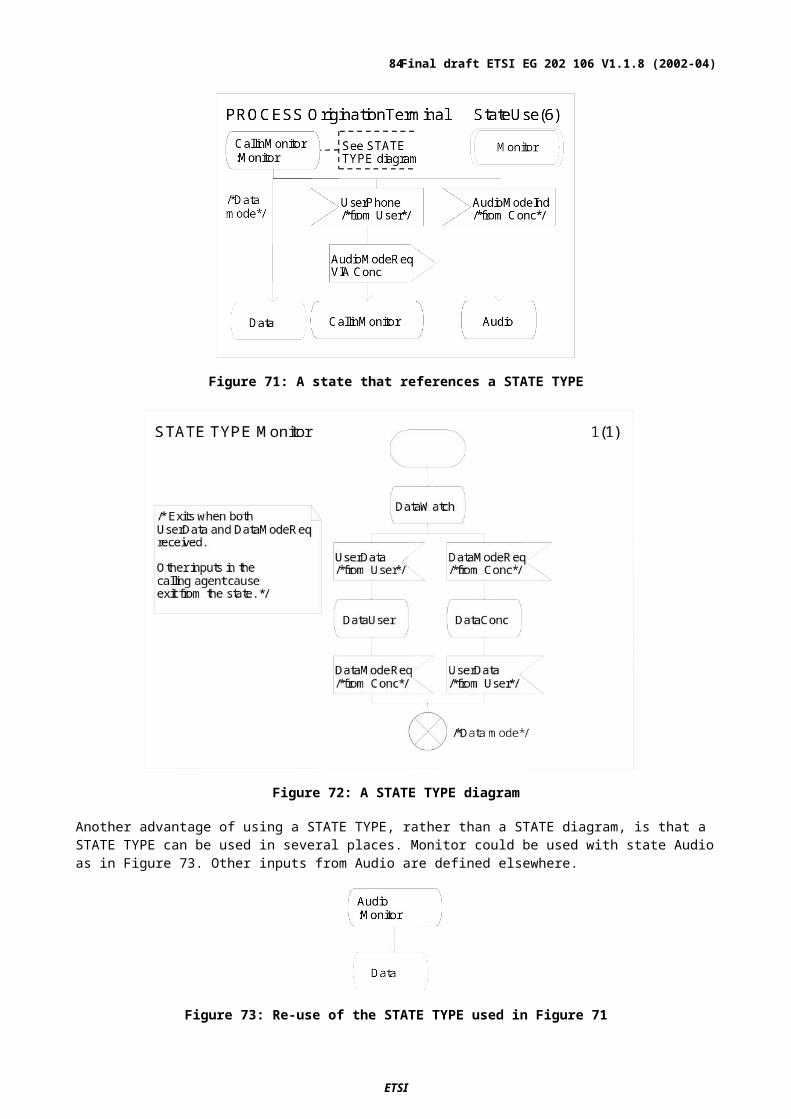
other HMSCs should be used within HMSCs to ensure that a logical structuring of described behaviour is achieved. This has the added advantage of keeping to a minimum the number of symbols in any one HMSC.
An MSC Reference may contain a textual operator expression instead of a single Reference name. The textual expression offers the same expressiveness as the graphical notation with the one exception that loop boundaries can be given in the textual form. MSC Reference expressions are useful for a compact representation, in particular of several alternatives, but makes the description less intuitive. To improve readability ,(122) graphical HMSC expressions should be used in preference to textual Reference expressions.
Figure 81: HMSC with reference expression and corresponding HMSC with graphical relations between the references
117 MSC reference in basic MSC
Behaviour parts can also be reused or abstracted in basic MSCs by using MSC References connected to the instances. In general, the number of MSC References should be kept low within a plain MSC in order to focus on the message interchange.
HMSC References may be included in basic MSCs but referring to "overview" charts from detailed sequence specifications can be confusing. Therefore, (123)Plain MSCs should not include HMSC References.
MSC References in basic MSCs should be used as a structuring means and for the reuse of scenarios. Figure 82 shows an example of MSC References used in the specification of a test purpose preamble and postamble. As such, the MSC Reference plays a similar role to that of a procedure in SDL. (124)If the same scenario appears in several MSCs, it should be specified as an MSC of its own and referenced from other MSCs.
ETSI
Final draft ETSI EG 202 106 V1.1.8 (2002-04)84

Figure 82: MSC references in basic MSC
To ensure readability, (125)each message involved in an MSC (?that is referenced from a basic MSC?) should have both its output and input described within the diagram.
118 Inline expression
An inline expressions can be looked upon as an expanded form of an MSC Reference expression used in a basic MSC context. They are ideally suited to the compact description of several small variants, typically covering only a small section of the complete MSC which means that the inline expression should contain only a few events. (126)When it is not feasible to use MSC References to describe different sequence structures, inline expressions should be used.
Inline expressions are used to define concisely several different sequences that can occur at the same place in the enclosing diagram. A diagram using an inline expression is equivalent to several diagrams where the inline expression is replaced by each of the defined sequences in turn. Inline expressions can use the following operators on events:
sequence (seq);
alternative (alt);
optionality (opt);
repetition (loop);
parallelism (par);
exception (exc).
Inline expressions can be nested. Inline expressions give the benefit of conciseness at the expense of making a specification more complex and, thus, more difficult to read. (127)The use of multiple inline expressions in a single MSC diagram should be limited to avoid an unnecessary explosion in the number of implicit scenarios.
ETSI
Final draft ETSI EG 202 106 V1.1.8 (2002-04)85
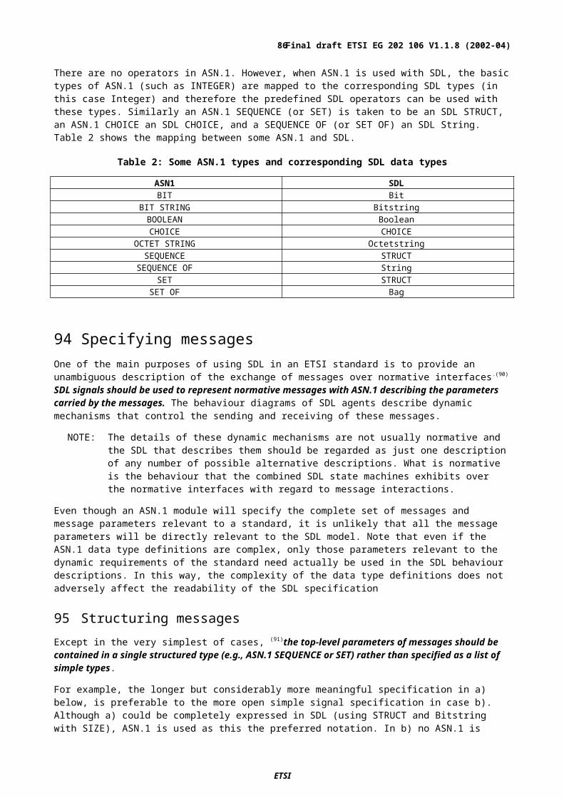
Figure 83: Usage of inline expression
If inline expressions are used,(128) each message involved in an inline expression should have both its output and input described within the inline expression in order to make an intuitive description.
In certain situations, inline expressions are the only descriptive way to illustrate a scenario. For example, after setting a timer an alternative can be used to describe both the normal course of action and the exceptional behaviour resulting from a timeout. A scenario with two or more alternative courses of action might either be described in an HMSC, where the alternative is described by different MSC References on alternative paths, or in a basic MSC, where the alternative is described by alternative inline expressions. (129)HMSCs should be used to highlight significant alternative or optional behaviour paths but; if the differences are only minor, these could be described within an MSC using inline expressions.
119DataAlthough in many cases it is not necessary to model data within an MSC in a standard, it can sometimes be beneficial to use data related more to the description than to the described system. An example of this usage is specification data needed to reduce the complexity of the behaviour (e.g. loop boundaries and guard conditions on alternatives).
An example of using system related data in MSC is describing or limiting the parameter data that can be sent by messages, see Figure 84.
A consequence of using data in MSC is that the specification becomes more detailed and complex. If message parameters should be stated when describing message passing, then the message needs to be declared in advance, together with the data type declarations in a surrounding MSC document.
When data (type information or values) can enhance the understanding of an MSC, this may be indicated informally by notes, comments or informal actions, see Figure 86. To formally express data in MSC can lead to an unnecessarily complex specification that can be difficult to understand and maintain.
ETSI
Final draft ETSI EG 202 106 V1.1.8 (2002-04)86
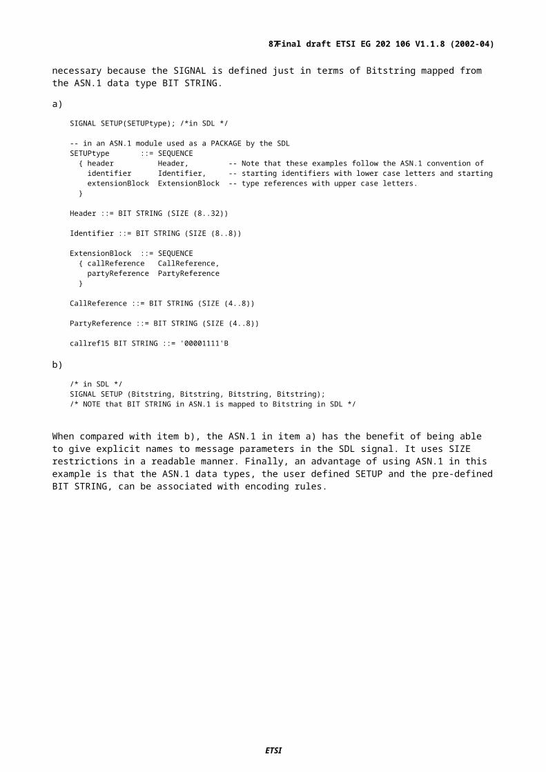
(130)Data types and expressions introduce complexity to a specification and it is therefore preferable to omit them from MSC diagrams. As an alternative, annotations may be added to describe the data if more detail is needed. Data should be described formally in MSC only when greater formality than can be achieved by using annotations is required.
Figure 84: Formal usage of data in MSC
120MessageAn MSC message describes two asynchronous events: a sending event that is performed by the sending instance and a receive event that is handled by the receiving instance. The receive event is optional (see 121).
Messages may cross instances that are placed between the sender and receiver . By rearranging the order of the instances, instance crossing messages can be minimized. (131)The crossing of MSC instances by messages should be minimized by placing frequently communicating instances close to each other wherever possible. However, the natural and logical ordering of entities should be considered to be more important than strict adherence to this guideline.
A message arrow may be drawn either horizontally or with a downward slope. Both forms are equivalent but the downward slope is sometimes used informally to indicate the passage of time. Since this is prone to misinterpretation, (132)delay or the passage of time should be described by the time concepts in MSC (see 126).
Messages with downward slopes can also be used to describe the overtaking of messages. However, (133)the unnecessary crossing of messages should be avoided since it obscures the meaning of an MSC, see Figure 85.
In general, two or more events may not be attached to the same point or at the same level on an instance axis. There is one exception to this rule. An incoming event and an outgoing event may be attached to the same point or at the same height. This is interpreted as if the incoming event is drawn above the outgoing event.
Although both representations are equivalent, within a standard, (134)an MSC should show an outgoing event below the incoming event that preceded it as this presentation gives a clearer description of the ordering relationships.
The two diagrams in Figure 85 are semantically equivalent, but the layout in MSC m2 makes the scenario easier to comprehend.
ETSI
Final draft ETSI EG 202 106 V1.1.8 (2002-04)87
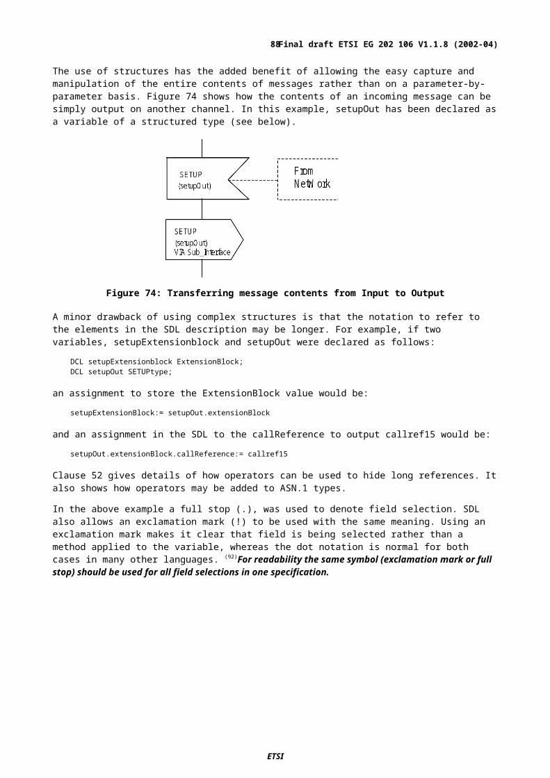
Figure 85: Clear ordering of events and separation of message lines
MSC does not require the parameters of the message to be described. However, providing an informal type name in a message is often useful when creating an SDL specification with an MSC model as input. In some cases, it might also be of value to indicate that a parameter has a certain value if this improves the understanding of the scenario. In protocol standards it is not unusual for a message to have an extensive parameter list defined and the inclusion of such lists with all messages can make an MSC very difficult to read.
The description of MSC message parameters may differ from SDL signal parameters regarding the level of detail. In a single scenario, it is common to highlight only the interesting aspects of the message parameters i.e.; the part that affects the further behaviour of the scenario. This abstraction is a very useful mechanism that ensures that the scenarios are not too detailed and complex.
MSC message parameters have a formal meaning in that they illustrate how values are transmitted together with the message. These values must conform to the corresponding parameter data type in the message declaration. However, in the interests of clarity, (135)only those parameters that are absolutely necessary for the understanding of the message sequence should be included with an MSC message. In order to be able to do this while still complying with the MSC syntax, (136)if incomplete message parameter information is to be shown in an MSC, this should be given in a note, following the message name as shown in Figure 86.
Figure 86: Indication of message parameter information
121 Incomplete messagesBesides the specification of successful transmission of messages, incomplete messages can be described in MSC. An incomplete message communication is represented by a lost message symbol or a found message symbol. A lost
ETSI
Final draft ETSI EG 202 106 V1.1.8 (2002-04)88
message is a message output for which the message input is unknown. A found message is a message input for which the message output is unknown. Lost messages may be used to describe the reaction of a system in error cases such as in case of an unreliable transmitter.
(137)Lost and found message should normally not be used in MSCs because they correspond either to the behaviour of the environment or the behaviour of the underlying system. They should not be used to describe traces of normal behaviour of systems.
A situation where a lost message may be used is in a scenario that describes how re-sending of lost messages is handled. Found messages may be used when a message can be sent by several possible instances, and the sending identity is not relevant to the scenario.
In SDL, unsuccessful signal transmission can only be described in an indirect manner.
Figure 87: Lost and found message
122ConditionMSC conditions can be used in two different ways:
as setting conditions;
as guarding conditions.
Setting conditions define the actual system state of the instance(s) that share the condition. Guarding conditions are used to restrict the possible ways in which an MSC can continue.
Local setting conditions can be used to indicate system states corresponding to states in SDL. The number of used local conditions should be minimized in order to not obscure the primary function described by the MSC. Local guarding conditions may contain a Boolean expression where variables are allowed. To make the description easy to understand, (138)logical names should be used in MSC guarding conditions instead of variable expressions.
Conditions have no further meaning. They are not events and a global condition does not imply synchronization between the shared instances.
Global conditions are attached to all instances contained in an MSC and denote global system states. Conditions are used in HMSCs to indicate global system states or guards and impose restrictions on the MSCs that are referenced in the HMSC. Conditions also give extra context information for the basic MSC and makes the MSC specification model easier to maintain. An example of an MSC with a global initial condition (guard) and a global final (setting) condition is shown in Figure 88.
ETSI
Final draft ETSI EG 202 106 V1.1.8 (2002-04)89
Figure 88: Global guard and setting conditions used to restrict composition of scenario parts
123ActionIn some situations, it can be useful to indicate informally the action that is performed after a message is received (see Figure 75). This is possible by using an informal action. (139)Use of the MSC action symbol should be limited to the informal expression of a specific aspect of behaviour, which helps to clarify the surrounding message sequence, and to data assignments.
124TimerTimers may be used informally to indicate delays or time constraints on event sequences. Since there is an explicit notation in MSC for time constraints and measurements (see 126), this should be used instead of timers as the notion of a timer entity may be too precise for most standard specifications.
ETSI
Final draft ETSI EG 202 106 V1.1.8 (2002-04)90

Figure 89: Timer usage
Note The WaitForSelection timer is used to restrict the waiting time for a response signal. The DisplayDelay timer is used as a delay in the execution.
In certain situations when using separated timer symbols, it is necessary to add an extra timer identifier in order to have an unambiguous scenario.
Figure 90: Separated timer symbols and timer identifier
ETSI
Final draft ETSI EG 202 106 V1.1.8 (2002-04)91
125Control FlowIn specifying distributed systems, all communication is normally described by asynchronous messages. It is however often the case that communication is by signal pairs, a call message and a corresponding reply message, together making a synchronous communication.
A logically connected signal pair might be high-lighted in an MSC specification by using the special symbols for reply, method and suspend.
The control flow concepts are:
method call;
reply symbol;
method symbol;
suspend symbol.
A method call is represented by a message symbol with the CALL keyword before the message name. For a method call, there must always be a corresponding reply, and vice versa.
The method symbol is used to indicate that an instance is active. The suspension symbol is used to indicate that an instance is suspended, typically waiting for the reply of a blocking method call. The normal instance axis means that the instance is inactive, waiting for an activating event or a task to perform.
A method call followed by a suspension region is a synchronous method call.
If MSC Instances are used to represent entities that are not independent (asynchronously parallel), then the method and suspend symbols can be used to indicate how each active object gets the flow of control from the CPU.
Figure 91: Specification of synchronous communication utilizing the suspend symbol and the method symbol
126TimeThe time concepts can be used for:
Time measurements
Timing constraints on or between events
ETSI
Final draft ETSI EG 202 106 V1.1.8 (2002-04)92

Time constraints are useful for stating time requirements without adding behaviour to the model (compare with the use of timers). Using the time concepts assumes that a data type for handling time expressions is available.
NOTE: The time between sending the CallRequest message and receiving the CallRequestAck message should be within the range 10 to 60 time units.The time it takes to send the SETUP message is measured and saved into the time variable rel1 and should take no more than 20 time units.The relative time constraint [0.5*rel1, 2*rel1] requires that the time it takes to send the CALL_PROCEEDING message should be at least 0.5*rel1 and at most 2*rel1.
Figure 92: Time constraints between events
127General ordering and coregionAlthough an instance describes a total order of its events, an MSC normally describes only a set of partial event orders. This is because instances are independent, since each MSC instance is asynchronously parallel. Synchronization between instances is normally achieved by message passing.
Figure 93: Event orders of MSCs
Coregions are useful for describing situations where two or several events might happen in an arbitrary order on one instance. They are also commonly used on decomposed instances to relax the total ordering imposed to the contained instances by the decomposed instance. However, large coregions, covering many events might be very hard to interpret. Thus, (140)the number of events shown in an MSC coregion should be limited.
In Figure 94, the four messages that are sent to the Server can be received in any order by the Server instance. However, the first Info message must arrive after the second Info_Req is sent and the two Info_Req messages must be sent in a specific order.
ETSI
Final draft ETSI EG 202 106 V1.1.8 (2002-04)93

Figure 94: Use of coregion
General ordering can be used within a coregion to specify partial orders in an otherwise completely unordered region. However, (141)an inline alternative expression should be used in an MSC instead of general ordering within a coregion.
In the left diagram in Figure 95, the order restrictions that existed in the example in Figure 94 are released. On the other hand, there are a number of unwanted event orders in this MSC. An InfoEnd message can for example be consumed before its corresponding Info message.
In the right diagram in Figure 95, each message triplet is now ordered, but the three events related to the communication with Client_a is unordered with respect to the events related to the Client_b communication. (The Info_Req and Info events on the Server are ordered by the imposed ordering at the Client instance.)
Figure 95: General ordering within a coregion reduces the number of orders
128Relationship between MSC and UML Sequence DiagramsSequence diagrams in UML and MSC have many similar concepts and also have the same basic scope. For normal message interchange between instances, Sequence diagrams provide the same expressiveness as MSCs. However,
ETSI
Final draft ETSI EG 202 106 V1.1.8 (2002-04)94
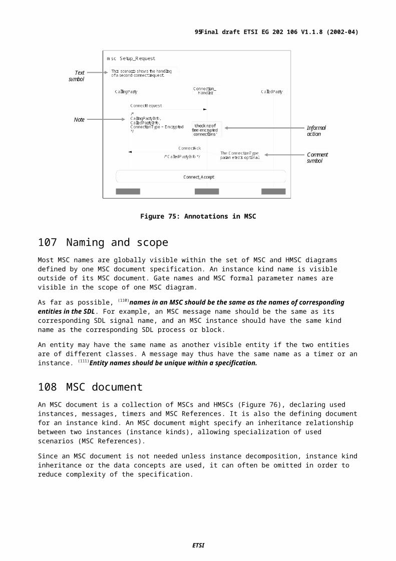
Sequence diagrams in UML 1.4 lack concepts to relate scenarios to each other (operators and MSC references), and should only be used for small, isolated scenario descriptions.
Figure 96: UML sequence diagram and corresponding MSC
ETSI
Final draft ETSI EG 202 106 V1.1.8 (2002-04)95

Annex A (informative):Reserved words
A.1 SDL
A.1.1 KeywordsThe following words are keywords in SDL and cannot be used as names.
NOTE: The list of keywords shows only the lower-case presentation. The upper-case equivalent of each is also an SDL reserved word.
abstract active adding aggregationalternative and any asassociation atleast block breakcall channel choice commentcomposition connect connection constantscontinue create dcl decisiondefault else endalternative endblockendchannel endconnection enddecision endexceptionhandlerendinterface endmacro endmethod endobjectendoperator endpackage endprocedure endprocessendselect endstate endsubstructure endsyntypeendsystem endtype endvalue envexception exceptionhandler export exportedexternal fi finalized fromgate handle if importin inherits input interfacejoin literals loop macromacrodefinition macroid method methodsmod nameclass nextstate nodelaynone not now objectoffspring onexception operator operatorsoptional or ordered outoutput package parent priorityprivate procedure protected processprovided public raise redefinedreferenced rem remote resetreturn save select selfsender set signal signallistsignalset size spelling startstate stop struct substructuresynonym syntype system taskthen this timer totry type use valuevia virtual with xor
ETSI
Final draft ETSI EG 202 106 V1.1.8 (2002-04)96
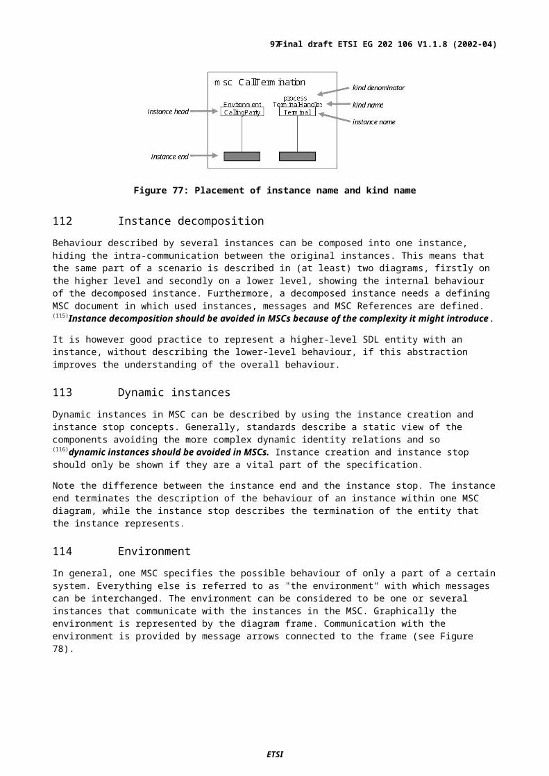
A.1.2 Predefined wordsThe following words are defined in ITU-T Recommendation Z.100 [4] in the SDL package "Predefined" and should not be redefined or used for any other purposes:
ACK Array Bag BELbit Bit bitstring BitstringBoolean BS CAN CharacterCharstring chr CR DC1DC2 DC3 DC4 delDEL DivisionByZero DLE DurationEM empty Empty emptystringENQ EOT ESC ETBETX Extract false FFfirst fix float HTincl Integer InvalidIndex InvalidReferenceIS1 IS2 IS3 IS4last length LF Makemkstring Modify NAK NaturalNoMatchingAnswer NUL num Octetoctetstring Octetstring OutOfRange Pidpower Powerset Predefined Realremove SI SO SOHString STX SUB substringSYN take Time trueUndefinedField UndefinedVariable Vector VT
A.2 MSCThe following words are keywords in MSC and cannot be used as names.
action after all altas before begin bottomcall comment concurrent conditionconnect create data decomposeddef empty end endconcurrentendexpr endinstance endmethod endmscendsuspension env equalpar escapeexc expr external finalizedfound from gate ininf inherits inline instinstance int_boundary label languageloop lost method mscmscdocument msg nestable nonnestableoffset opt otherwise outpar parenthesis receive redefinedreference related replyin replyoutseq shared starttimer stopstoptimer suspension text timetimeout timer to topundef using utilities variablesvia virtual when wildcards
ETSI
Final draft ETSI EG 202 106 V1.1.8 (2002-04)97

A.3 ASN.1The following words are keywords in ASN.1 and cannot be used as names.
ABSENT ABSTRACT-SYNTAX ALL APPLICATIONAUTOMATIC BEGIN BIT BMPStringBOOLEAN BY CHARACTER CHOICECLASS COMPONENT COMPONENTS CONSTRAINEDDEFAULT DEFINITIONS EMBEDDED ENDENUMERATED EXCEPT EXPLICIT EXPORTSEXTENSIBILITY EXTERNAL FALSE FROMGeneralizedTime GeneralString GraphicString IA5StringIDENTIFIER IMPLICIT IMPLIED IMPORTSINCLUDES INSTANCE INTEGER INTERSECTIONISO646String MAX MIN MINUS-INFINITYNULL NumericString OBJECT ObjectDescriptorOCTET OF OPTIONAL PDVPLUS-INFINITY PRESENT PrintableString PRIVATEREAL SEQUENCE SET SIZESTRING SYNTAX T61String TAGSTeletexString TRUE TYPE-IDENTIFIER UNIONUNIQUE UNIVERSAL UniversalString UTCTimeUTF8String VideotexString VisibleString WITH
A.4 UMLThe following words are cannot be used as names in UML.
«access» association «association» «become»«call» complete «copy» «create»«derive» derived «destroy» destroyed«document» documentation «executable» «facade»«file» «framework» «friend» Generalizationglobal «global» «implementation» «implementationClass»implicit «import» incomplete «instantiate»«invariant» «library» local «local»«metaclass» «metamodel» new overlappingparameter «parameter» persistence persistent«postcondition» «powertype» «precondition» «process»«realize» «refine» «requirement» «responsibility»self «self» semantics «send»«signalflow» «stub» «systemModel» «table»«thread» «topLevel» «trace» transient«type» «utility» xor
ETSI
Final draft ETSI EG 202 106 V1.1.8 (2002-04)98

Annex B (informative):Summary of guidelinesTable B.1 provides a summary of the guidelines for the use of SDL for descriptive purposes. This summary should be read in conjunction with the main body of text in the present document.
Table B.1: Summary of guidelines
Identifier
Guideline
NAMING CONVENTIONS1 A naming convention that can be applied consistently to each notation used should be chosen2 While it is acceptable to use the underscore character to delineate words within most SDL entity names, it is
advisable to avoid the use of the dash character in ASN.1 types and values in order to avoid conflicts and misinterpretation in the associated SDL.
3 The general use of names which differ only in character case to distinguish between entities should be avoided.4 Care should be taken to ensure the consistent use of character case within names throughout an ASN.1, SDL,
MSC or UML specification5 Names of less than 6 characters may be too cryptic and names of more than 30 characters may be too difficult to
read and assimilate.6 The reserved words of all notations used within a standard should be avoided as defined names in each of the
individual parts7 Readability is improved if the same convention for separating words within names is used throughout a
specification8 In most cases an underscore character between each word removes any possibility of misinterpretation and this
is the approach that is recommended9 In more complex models where each block is made up of a number of processes, the use of the same name for a
block and one of its constituent processes is likely to cause confusion and should be avoided.10 The use of a single name for multiple purposes should be avoided wherever possible11 The addition of project-specific prefixes or suffixes can make meaningful names appear cryptic and should be
used with great care12 By giving blocks, processes and MSC instances names that represent the overall role that they play within the
system, it is possible to distinguish process names from procedure names. If carefully chosen, they can help to link the SDL and MSC back to the corresponding clauses in the text description
13 The name chosen for an SDL operation should indicate the specific action taken by the operation14 If possible, it is advisable to leave at least one significant word in the name unabbreviated as this can help to
provide the context for interpreting the remaining abbreviations15 The name chosen for an interface or signal list should indicate the general function of the grouped signals16 Where all signals between one block or process and another can be logically grouped together, signal list names
can be chosen to indicate the origin and the destination of the associated signals17 A state name should clearly and concisely reflect the status of the process while in that state18 If it is important to number states then this should be done in conjunction with meaningful names19 The name chosen for a variable should indicate in general terms what it should be used for20 Names used to identify constants can be more specific by indicating the actual value assigned to the constant21 The names of SDL data types should be capitalized while the names of literals and synonyms should begin with a
lower-case characterPRESENTATION AND LAYOUT OF DIAGRAMS
22 The general flow of SDL behaviour diagrams and UML statechart and activity diagrams should be from the top of the page towards the bottom
23 The flow on a page of an SDL process should end in a NEXTSTATE symbol rather than a connector24 States that are entered from NEXTSTATE symbols on other pages should always be placed at the top of the
page.25 Where transitions are short and simple they can be arranged side-by-side on a single page26 When two or more transitions are shown on one page, there should be sufficient space between them to make
their separation clear to the reader27 Connector symbols should generally only be used to provide a connection from the bottom of one page to the top
of another28 All reference symbols and text boxes containing common declarations should be collected together at a single
point within the process diagrams.29 Separate text box symbols should be used for each different type of declaration30 Activity diagrams or statechart diagrams should use text boxes indicate what functions are specified in other
diagrams or in which diagram the behaviour continues
ETSI
Final draft ETSI EG 202 106 V1.1.8 (2002-04)99
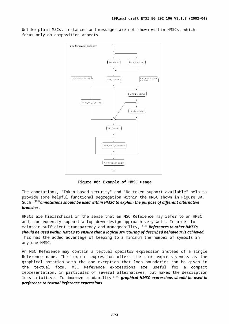
Identifier
Guideline
31 When the text associated with a task symbol overflows its symbol boundaries, a text extension should be used to carry the additional information
32 Symbols that terminate the processing on a particular page should be aligned horizontally33 In simple systems where each process communicates with only one or two other processes, the orientation of
INPUT and OUTPUT symbols can be used to improve the readability of the SDL. However, to avoid possible specification errors and misinterpretation, explicit methods of identifying the source and destination of signals should be used
34 If used, the significance of the orientation of SDL symbols should be clearly explained in the text introducing each process diagram
35 A state, input and the associated transition to the next state should be contained within a single SDL page36 Process diagrams should segregate normal behaviour from exceptional behaviour.
USING PROCEDURES, OPERATIONS AND MACROS37 The use of procedures to modularize specifications and to 'hide' detail is strongly recommended38 Convert informal text descriptions of actions into procedure calls and replace the task symbols with a procedure
symbols39 All data relevant to the real behaviour represented by a procedure should be specified in the parameter list and
returned value (if any).40 In most cases it is preferable to use operations instead of value-returning procedures.41 Procedures should only read and write to variables that are passed to the procedure in the parameter list or are
declared within the procedure itself42 Procedures should specify a level of detail that is suitable for the particular purpose of the standard43 A functional procedure should fulfil its specified role and do nothing that could be considered to be a side-effect44 The processing of signals is one of the most important activities shown in the SDL of a protocol standard and
should normally be visible in the calling process rather than the called procedure45 It is important that procedures that specify a limited sequence of actions should be given names that reflect as
fully as possible the activity performed by a procedure46 Behaviour that could be considered a side-effect to its defined purposes, should not be specified in a procedure47 In the exceptional case that a procedure includes the specification of one or more states, it is important to ensure
that all signals which are not directly processed within the procedure are correctly handled for subsequent processing
48 The names of procedures having multiple effects should reflect each intended effect either individually or collectively
49 The textual syntax of SDL can be used to define simple operations50 Complex operations should be specified as operator or method diagrams which are referenced from the relevant
data type specification51 The use of macros should be limited to those cases where the macro can be contained within one printed page
USING DECISIONS52 It is essential that the complete range of values of the data type contained in the decision is covered by ranges of
values in the answers without any overlap53 Identifiers used in decisions should clearly reflect to a reader the 'question' and 'answer' nature of the conditions
being expressed.54 The use of informal text in decision statements should be limited, preferably to those cases where the decision is
obviously binary in nature55 In most cases, enumerated types rather than text strings should be used to express decisions.56 ELSE should be used as a decision outcome value to distinguish between one or more specific outcomes and all
other possibilities57 ASN.1 constraint or SDL SYNTYPE constructs should be used to limit the range of values represented by an
ELSE branch in a decision58 SDL SYNONYMs should be used to define meaningful alternatives to the Boolean values of true and false if this
aids clarity59 Procedure calls should be used in conjunction with decisions to eliminate the use of informal text60 The ANY expression should not appear in the SDL specifications in standards except where it is included to show
the behaviour of an entity (such as a user) that is not the subject of the standard61 Where mutually exclusive implementation options are to be expressed, the option symbol should be used rather
than a decision62 SDL algorithmic flow control expressions should be restricted to situations where the required behaviour involves
only the processing of data but not the sending of signals and not the control of timers.SYSTEM STRUCTURE, COMMUNICATION AND ADDRESSING
63 The SDL version of the architecture of a protocol or service should be consistent with and complementary to other (non-SDL) descriptive diagrams
64 Comments should be used to convey to the reader the relationship of the SDL architecture to the relevant non-SDL parts of the standard
65 The SDL specification within a standard should comprise one system composed of at least one agent66 SDL should be used to show the structure of a system as well as its behaviour
ETSI
Final draft ETSI EG 202 106 V1.1.8 (2002-04)100
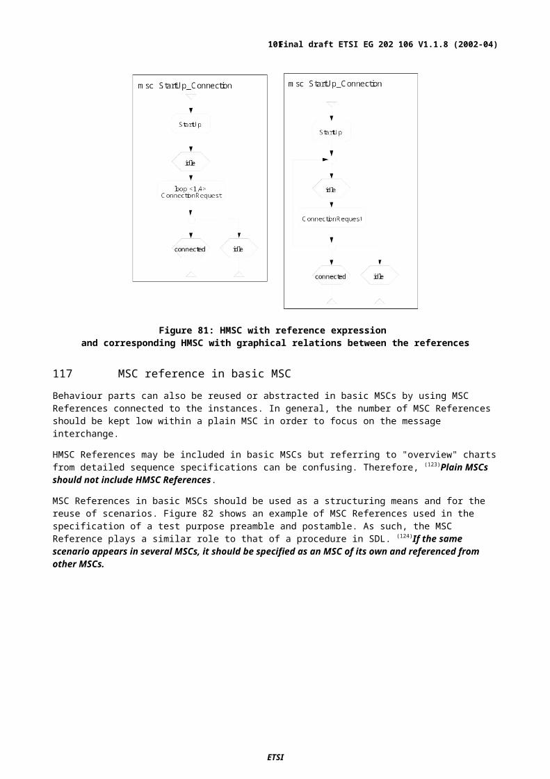
Identifier
Guideline
67 SDL sub-structuring should be used to simplify complex SDL models but should not be used excessively.68 Multiple instances of SDL blocks and processes should be avoided if possible69 Informative blocks or processes that are not needed to aid understanding should be omitted70 If the same block or process is required at more than one place within an SDL specification, a BLOCK TYPE or
PROCESS TYPE should be defined from which instances can be derived.71 Wherever possible, a minimal number of static instances should be used instead of dynamically created SDL
processes.72 A specification area diagram (if used) should include the most important packages shown as reference symbols
with dependency shown on the diagram.73 All normative channels (interfaces) should be clearly marked as being normative (using a comments box)74 There should be no more than one communication path specified in each direction between one entity and
another.75 Remote procedures, import/export, or shared data should not be used to exchange information between blocks
and processes76 A small number of interface names (preferably one) should be used to identify the signals on a particular channel
or gate77 All channels and gates should be shown with the associated interface names, signal list names or signals.78 TO or VIA should be used in an output symbol to indicate the recipient clearly if this is not obvious from the
structure of the SDL system79 A different signal (with a self descriptive name) should be defined for each distinct message event.80 The source of the signal in an input should be indicated either by its name or by a comment81 There should be only one signal in each output symbol.82 All the gates of an agent should be explicitly connected to channels.83 Gates should not be attached to block symbols or process symbols.84 Process definitions contained within process definitions should be avoided, unless the intention is to exclude
concurrent interpretation of processes85 The use of shared data should be avoided.86 A composite state should87 Use a STATE TYPE diagram rather than a STATE diagram.88 A standard should be defined so that the language-defined exceptions (such as OutOfRange) do not occur.
SPECIFICATION AND USE OF DATA89 ASN.1 should be used to specify data and the ASN.1 data definitions should be made common to both the SDL
specification and the non-SDL parts of a standard90 SDL signals should be used to represent normative messages with ASN.1 describing the parameters carried by
the messages.91 The top-level parameters of messages should be contained in a single structured type (e.g., ASN.1 SEQUENCE
or SET) rather than specified as a list of simple types92 For readability the same symbol (exclamation mark or full stop) should be used for all field selections in one
specification.93 If the parameters in a message have to appear in a fixed order, then the ASN.1 constructor SEQUENCE should
be used to specify the message contents94 If the parameters of a message may appear in any order, then the ASN.1 constructor SET should be used to
specify the message contents.95 When mapping messages described in another format (such as tables) to a simplified form as ASN.1 or SDL data
types, the structure of the simplified messages should be kept as close as possible to the structure of the original messages and the names of messages and their associated parameters should be preserved.
96 When there are data type specific operations for internal data, it is usually better to use SDL to define the data type rather than ASN.1 so that the operations can be defined as part of the data type.
97 For readability, in one SDL specification the same brackets (square – which are distinct from other uses, or round) should be used for all ARRAY, VECTOR and STRING indexing.
98 Whenever possible symbolic names should be used rather than explicit value denotations (such as 123, '0110'B).99 ASN.1 ENUMERATED or SDL literal list types should be used for data that consists of a collection of names
100 VALUE TYPE should be used to define a new data type in a specification while SYNTYPE should by used to rename or constrain the values of existing data types
101 OBJECT TYPE should be avoided as the data type for signal parameters102 OBJECT TYPE definitions(or a data type name prefixed by OBJECT) should be used only when the data cannot
be simply expressed with a VALUE TYPE.103 Any data type to define variables should be avoided
USING MESSAGE SEQUENCE CHARTS (MSC)104 When MSC is used in combination with SDL, a message input in MSC should correspond to a signal
consumption in SDL.105 Each MSC diagram should be limited to the information that fits into one printed page106 When used in a standard, an MSC diagram should always be surrounded by a diagram frame and have an
ETSI
Final draft ETSI EG 202 106 V1.1.8 (2002-04)101

Identifier
Guideline
attached name.107 A clear spacing between symbols in an MSC diagram should be maintained both horizontally and vertically108 An instance axis should always be terminated at the end by either an instance end symbol or a stop.109 Annotations help to improve the understanding of an MSC description and should be used freely.110 Names in an MSC should be the same as the names of corresponding entities in the SDL111 Entity names should be unique within a specification.112 If there is an associated SDL specification, each MSC instance should have a kind name and kind denominator
corresponding to the name and entity kind of the equivalent entity in SDL113 The number of instances included in an MSC should be kept low to maintain a focus on the normative interface(s)
and important entities in the logical or physical model114 If the kind name is present in an MSC instance, the instance head symbol should contain the instance name with
the kind name placed above the symbol115 Instance decomposition should be avoided in MSCs because of the complexity it might introduce116 Dynamic instances should be avoided in MSCs.117 Instances with instance kind name "environment" should be used to represent the environment in an MSC.118 HMSCs should be used to specify a high-level view of scenarios which are defined in other MSC or HMSC
diagrams.119 Connections should always be used when HMSC flow lines join or merge to distinguish them from simple
crossing lines.120 Annotations should be used within HMSC to explain the purpose of different alternative branches121 References to other HMSCs should be used within HMSCs to ensure that a logical structuring of described
behaviour is achieved.122 Graphical HMSC expressions should be used in preference to textual Reference expressions123 Plain MSCs should not include HMSC References124 If the same scenario appears in several MSCs, it should be specified as an MSC of its own and referenced from
other MSCs.125 Each message involved in an MSC (?that is referenced from a basic MSC?) should have both its output and input
described within the diagram126 When it is not feasible to use MSC References to describe different sequence structures, inline expressions
should be used.127 The use of multiple inline expressions in a single MSC diagram should be limited to avoid an unnecessary
explosion in the number of implicit scenarios128 Each message involved in an inline expression should have both its output and input described within the inline
expression129 HMSCs should be used to highlight significant alternative or optional behaviour paths but; if the differences are
only minor, these could be described within an MSC using inline expressions130 Data types and expressions introduce complexity to a specification and it is therefore preferable to omit them
from MSC diagrams. As an alternative, annotations may be added to describe the data if more detail is needed. Data should be described formally in MSC only when greater formality than can be achieved by using annotations is required.
131 The crossing of MSC instances by messages should be minimized by placing frequently communicating instances close to each other wherever possible
132 Delay or the passage of time should be described by the time concepts in MSC133 The unnecessary crossing of messages should be avoided since it obscures the meaning of an MSC134 An MSC should show an outgoing event below the incoming event that preceded it135 Only those parameters that are absolutely necessary for the understanding of the message sequence should be
included with an MSC message136 If incomplete message parameter information is to be shown in an MSC, this should be given in a note, following
the message name137 Lost and found message should normally not be used in MSCs138 Logical names should be used in MSC guarding conditions instead of variable expressions139 Use of the MSC action symbol should be limited to the informal expression of a specific aspect of behaviour,
which helps to clarify the surrounding message sequence, and to data assignments.140 The number of events shown in an MSC coregion should be limited.141 An inline alternative expression should be used in an MSC instead of general ordering within a coregion
ETSI
Final draft ETSI EG 202 106 V1.1.8 (2002-04)102

HistoryDocument history
V1.1.1 June 2001 1st draft, Scope & TOC
V1.1.2 August 2001 Addition of Naming clause
V1.1.3 October 2001 Addition of MSC, Decisions and Presentation clauses plus Introduction
V1.1.4 February 2002 Addition of Structuring Behaviour, Procedures & Data clauses
V1.1.5 February 2002 Addition of System structure, communication and addressing clause
V1.1.6 February 2002 Tidied version for review
V1.1.7 March 2002 Add definition of polymorphic
V1.1.8 April 2002 Pre-processed by the ETSI Secretariat editHelp! E-mail: mailto:[email protected]
ETSI
Final draft ETSI EG 202 106 V1.1.8 (2002-04)103