Embed Size (px)
Citation preview

Engineering Technical Laboratory Rev. 5
*This product is designed and produced by Embedded Wireless Laboratory Inc. for ETL.
ETL Programmer for MC9S12(X) Freescale Microcontrollers User Guide
© ETL &EWL 2015-2016 Microcontroller Development Tool

©ETL & EWL (2013-2016) ETL Programmer for MC9S12(X) Freescale Microcontrollers User Guide 2
TABLE OF CONTENTS
1. PREFACE ....................................................................................................................................... 3
2. CHECKLIST AND REQUIREMENTS ......................................................................................... 4
3. HARDWARE SUMMARY ............................................................................................................ 5
4. MANUAL USB DRIVERS INSTALLATION (WINDOWS 7).................................................... 7
5. USB DRIVER UNINSTALLATION ........................................................................................... 12
6. SOFTWARE ACTIVATION ....................................................................................................... 13
7. FILES DOWNLOAD ................................................................................................................... 15
8. CAS4 MC9S12XEP100 (5M48H) PRACTICE ........................................................................... 16
9. WARRANTY STATEMENT ....................................................................................................... 24

©ETL & EWL (2013-2016) ETL Programmer for MC9S12(X) Freescale Microcontrollers User Guide 3
1. PREFACE
This manual will guide you through the installation and operation of the ETL Programmer
for MC9S12(X) Freescale Microcontrollers, referenced hereafter as the MC9S12(X)-Programmer.
The MC9S12(X)-Programmer has been designed for programming EEPROM/DataFLASH/FLASH memory in the Freescale MC912/MC9S12/MC9S12X microcontrollers (MCU):
MC9S12XEP100 (5M48H) MC9S12H256 (1K78X) MC9S12XEP100 (1N35H) MC9S12HZ256 (3L16Y) MC9S12XEQ384 (3M25J) MC9S12H128 (1K78X) MC9S12XET256 (0M53J, 2M53J) MC9S12D64 (2L86D) MC9S12XDP512 (0L15Y, 1L15Y) MC68HC912D60 (4F73K) MC9S12DB128B (0L85D) MC68HC12D60 (0K13J) MC9S12DT128B (1L85D) MC68HC912D60A (2K38K) MC9S12DG128 (5L40K) MC68HC912DG128A (0L05H) MC9S12DG128 (1L59W) MC68HC912DC128A (3K91D) MC9S12DG256 (2K79X) MC68HC912DG128 (0K50E) MC9S12A512 (4L00M) MC68HC912DC128 (0K50E) MC68HC912B32 (4J54E) MC68HC12BE32 (0J38M)
Coming soon free of charge: MC9S12DP512 (1L00M)
The MC9S12(X)-Programmer has been tested on the following modules: BMW CAS4 (61.35-9 241 971.9-01) BMW CAS4 (61.35-9 247 480.9-01) BMW CAS4 (61.35-9 257 036.9-01) BMW CAS4 (61.35-9 268 749.9-01) BMW CAS4 (61.35-9 268 749.9-02) BMW CAS4 (61.35-9 268 751.9-01) BMW CAS4 (61.35-9 282 118.9-02) BMW CAS4 (61.35-9 293 391.9-01) BMW CAS4 (61.35-9 299 333.9-01) BMW CAS4 (61.35-9 301 518.9-01) BMW CAS4 (61.35-9 301 522.9-01) BMW CAS4 (61.35-9 359 011.9-01) GM SRS
Note: Most number of devices can be programmed in two operating modes, In-Circuit and On-Board.
Note: Use On-Board programming when device is secured or the BDM module disabled.
Note: Any devices not mentioned above can’t guarantee for correct reading or programming by MC9S12(X)-Programmer.

©ETL & EWL (2013-2016) ETL Programmer for MC9S12(X) Freescale Microcontrollers User Guide 4
2. CHECKLIST AND REQUIREMENTS
The following describes what items are provided with the MC9S12(X)-Programmer:
One ETL HyperF Programmer One Switching Power Supply: +12V, 2A One USB-mini cable Two MC9S12XE LQFP-144 adapters One MC9S12XD LQFP-144 adapter MC9S12(X)-Programmer PC software on CD-ROM – Optional Extra
Personal Computer system requirements:
Desktop/Laptop PC with a USB Port Windows XP/7/8/10 64/32-bit
Note: The Windows XP PC must have Microsoft.NET Framework 3.5 SP1 installed. Download it from the following link:
http://www.microsoft.com/downloads/thankyou.aspx?familyId=ab99342f-5d1a-413d-8319-81da479ab0d7&displayLang=en

©ETL & EWL (2013-2016) ETL Programmer for MC9S12(X) Freescale Microcontrollers User Guide 5
3. HARDWARE SUMMARY
The MC9S12(X)-Programmer uses the ETL HYPERF PROG board to access the target
MCU (Figure 1). To achieve high-performance and high-reliability, the ETL HYPERF PROG hardware incorporates the following modules:
High-performance 2 channel FTDI USB chip at 480Mbit/s speed High-performance ARM 32 Microcontroller Unit with Floating Point Unit. It runs
embedded OS with multithread tasks. High Frequency 400 MHz Complex Programmable Logic Device (CPLD)
incorporates all high-speed logic functions as well as BDM communication protocol. Input and output Over-voltage and Over-current protection implemented by the zener
diodes and resettable fuses. High current voltage regulator for 3.3/5 Volt output on BDM connector. Isolated DC/DC converter for supplying +5 Volt for On-board interface. An Optical Isolated In-Circuit interface to provide maximum safety at the time of
connection and programming. Three LEDs and a 'Power Off ' button to monitor and control power and operation
progress status. High-quality and high tolerance 1% parts were used to build every hardware. Best in industry cryptographic security device to prevent hardware cloning and
physical attacks.
USB Port
Input +12VPower Port
Isolated DC/DCConverter
High-performanceUSB 2.0 Chip480 Mbit/s
USB PowerOK LED
Programmer Progressand status LED High-performance
180 MHz ARM32MCU+FPU
InputProtectionResettableFuse
OutputProtectionResettableFuse
Voltage Regulator12V to 5/3.3Vwith Over-voltageand Over-currentprotection
Opto-isolatorfor In-CircuitMode
BDMConnectorfor In-CircuitMode
OutputVoltageOK LED
High-frequencyCPLD device
On-Board Connectorfor Secured MCURead/Program
Figure 1. The ETL HYPERF PROG board layout

©ETL & EWL (2013-2016) ETL Programmer for MC9S12(X) Freescale Microcontrollers User Guide 6
The ETL HYPERF PROG board includes three LEDs (Figure 2). LEDs indicate HYPERF PROG state and external power supply voltage (Table 1-3).
GREEN USB cable connected and voltage applied to the HYPERF PROG. DARK No voltage applied to the HYPERF PROG. Check the USB Connector and
cable. Try another PC USB port. Table 1. USB POWER LED color meaning
GREEN The output voltage for target MCU is present on In-Circuit or On-Board
Connectors. The voltage is in the valid range. DARK No voltage applied to a target MCU, or the voltage is not in the valid range.
Table 2. Output Voltage LED color indicatiors
GREEN 1Hz FLASHING
The HYPERF PROG is in the normal operation mode, and it is ready to receive commands.
GREEN Slow FLASHING
The HYPERF PROG Internal Task is Running. No user action required.
GREEN Fast FLASHING
The HYPERF PROG Internal +3.3 Volt is out of range, usually lower. Make sure the USB cable is not damaged, or PC USB port outputs are +5 Volts.
DARK The HYPERF PROG power is off, or the firmware corrupted. Use 'Firmware Update' procedure to recover firmware
Table 3. Progress Status LED color indicatiors
Note: In On-Board mode always use 'Power Off' button to turn off the power from the target MCU before removing it from the socket. Ignoring this will result in target MCU FLASH corruption!
O u tp u t Vo ltag eO ka y L E D
B DMCo nn e cto r
P o we r OffB u tto n
USB Ca bleCon ne ctor
US B P o werO K L ED
In pu t +1 2 Vo ltC on ne ctor
O n- bo ar d Co nn e cto r
for se cu re d MCU s
o r fa st Rea d /P ro gr am
Prog re ssSta tu s LE D
Figure 2. The ETL HYPERF PROG enclosure view

©ETL & EWL (2013-2016) ETL Programmer for MC9S12(X) Freescale Microcontrollers User Guide 7
4. MANUAL USB DRIVERS INSTALLATION (WINDOWS 7) USB Driver should be installed automatically after the ETL HYPERF PROG is plugged in. In
case it fails, follow the instructions below. This section describes how to install the USB drivers for the MC9S12(X)-Programmer on the
Windows 7 OS. The ETL HYPERF PROG uses the driver supplied by “FTDI Chip” company. The Product ID (PID) was changed to meet the design requirements.
Please follow next steps to install the driver: Download the MC9S12(X)-Programmer software from the ETL website. Install the software. After installation, the driver will be located in the "C:\Program
Files (x86)\ETL\ETL Freescale Programmer\USB Driver\" directory. Plug the HYPERF PROG board into a USB port. Wait until the Windows 7 fails to install the driver (Figure 3), then follow the steps
below.
Figure 3. The "Windows 7" driver installation failed
Open the "Device Manager" and locate "ETL HyperF Programmer" devices (Figure 3).
Figure 4. The "ETL HyperF Programmer" devices in the "Device Manager".
Right Click on the first "ETL HyperF Programmer" device and then select "Update
Driver Software" menu item.(Figure 5).
Figure 5. The "Update Driver Software" menu item selection

©ETL & EWL (2013-2016) ETL Programmer for MC9S12(X) Freescale Microcontrollers User Guide 8
Select the "Browse my computer for driver software" (Figure 6).
Figure 6. Update Driver Software - "ETL HyperF Programmer"
Press the "Browse" button to choose the USB driver location. For Windows 7 32-bit,
the location will be "C:\Program Files\ETL\ETL Freescale Programmer\USB Driver". For Windows 7 64-bit the location will be "C:\Program Files (x86)\ETL\ETL Freescale
Programmer\USB Driver\".
Figure 7. Update Driver Software - "ETL HyperF Programmer"
Checkmark the "Include subfolders" box. Click the "Next" Button.

©ETL & EWL (2013-2016) ETL Programmer for MC9S12(X) Freescale Microcontrollers User Guide 9
In a couple of seconds, the Windows security alert screen will appear. Make sure the drivers are signed by "EMBEDDED WIRELESS LABORATORY Inc."
Press the "Install" button (Figure 8)
Figure 8. "Windows Security" alert
Wait for the "Update Driver Software" screen to appear (Figure 9)
Figure 9. Successful "Update Driver Software " screen
Note: If an error occurred during the driver installation, the user might not have administrative rights on this Windows account. Log in as an Administrator and repeat steps described above.

©ETL & EWL (2013-2016) ETL Programmer for MC9S12(X) Freescale Microcontrollers User Guide 10
One driver was installed successfully (Figure 10). Install another driver for the "ETL Hyper Programmer” in the same way.
Figure 10. The "ETL Crypto Authentication" device successful installation
Open the "Device Manager" and locate "ETL Hyper Programmer" devices (Figure 3). Right click on the first "ETL Hyper Programmer" device and then select the "Update
Driver Software" menu item.(Figure 5). Select the "Browse my computer for driver software" (Figure 6). Press the "Next" button. In a couple of seconds the Windows security alert screen will appear. Select the
"Install this driver software anyway" (Figure 8). Finally you will see the driver installation confirmation for the second device. (Figure
11).
Figure 11. The "ETL Hyper Programmer" device successful installation

©ETL & EWL (2013-2016) ETL Programmer for MC9S12(X) Freescale Microcontrollers User Guide 11
To make sure that the drivers were installed successfully open the "Device Manager"
and locate the "ETL Crypto Authentication" and the "ETL Hyper Programmer" (Figure 12).
Figure 12 The "ETL Crypto Authentication" and "ETL Hyper Programmer" devices

©ETL & EWL (2013-2016) ETL Programmer for MC9S12(X) Freescale Microcontrollers User Guide 12
5. USB DRIVER UNINSTALLATION The USB driver un-installation will be helpful if "Windows" automatically installs the
incorrect driver. This section describes how to uninstall the USB driver for the MC9S12(X)-Programmer. The ETL HYPERF PROG uses the driver supplied by “FTDI Chip” company. The Product ID (PID) was changed to meet the design requirements. The Product PID of the HYPERF PROG is 6692. The Vendor ID (VID) remained the same 0403. To uninstall the driver, we will use the CDMUninstaller software provided by “FTDI Chip” company. Download software at the http://www.ftdichip.com/Support/Utilities.htm website.
Please follow next steps to uninstall the driver: Unplug the HYPERF PROG board from USB port. Run the "CDMuninstallerGUI.exe" file. Change the PID to 6692 (Figure 13). Click the "Add" button. Click the "Remove Devices" Button.
Figure 13 The Drivers uninstalled by CDM Uninstaller software
If there were installed drivers in the system, you would see the confirmation of un-
installation.

©ETL & EWL (2013-2016) ETL Programmer for MC9S12(X) Freescale Microcontrollers User Guide 13
6. SOFTWARE ACTIVATION
This section describes the software activation procedure. For activation, the customer will need the "License key" provided at the time of MC9S12(X)-Programmer purchase. The "ETL HYPERF PROG" board connected to the USB port and the drivers previously installed. Note that the software can be activated on five computers only. If you are going to activate the MC9S12(X)-Programmer software on more computers, please contact the ETL technical support. Activation is valid for 14 days. After that period, a user has to activate the software again. The activation procedure is done automatically via the Internet. Make sure there is an Internet connection before activation process. Follow the next steps to complete the registration process: Connect the ETL HYPERF PROG board to the computer. Execute the MC9S12(X)-Programmer software. Press the "Connect Programmer" button. Wait until the "ETL Programmer is connected!" and the HYPERF PROG serial number
message is displayed.
Figure 14 MC9S12(X)-Programmer software activation, step 1
Select the "License" menu item and then press the "Register Product" button. Press the "Read" button to read the HYPERF PROG board serial number. (Figure 15). Compare this serial number with the serial number provided together with the license
key. Enter License Key. Press the "Activate" button. After Activation process completed the "Registration Status" must be "REGISTERED"
and "Clock Manipulation" is "NOT DETECTED". The ' Clock Manipulation' term stands for Windows OS's date and time manipulation.

©ETL & EWL (2013-2016) ETL Programmer for MC9S12(X) Freescale Microcontrollers User Guide 14
Figure 15 MC9S12(X)-Programmer software activation, step 2
Figure 16 Successful MC9S12(X)-Programmer software activation
Note: If activation procedure failed, please contact ETL technical support at the Email: [email protected]
Note: If clock manipulation is detected, Windows OS will be compromised and there is no viable way to fix this. Use another clean OS to install MC9S12(X)-Programmer software.
©ETL & EWL (2013-2016) ETL Programmer for MC9S12(X) Freescale Microcontrollers User Guide 15
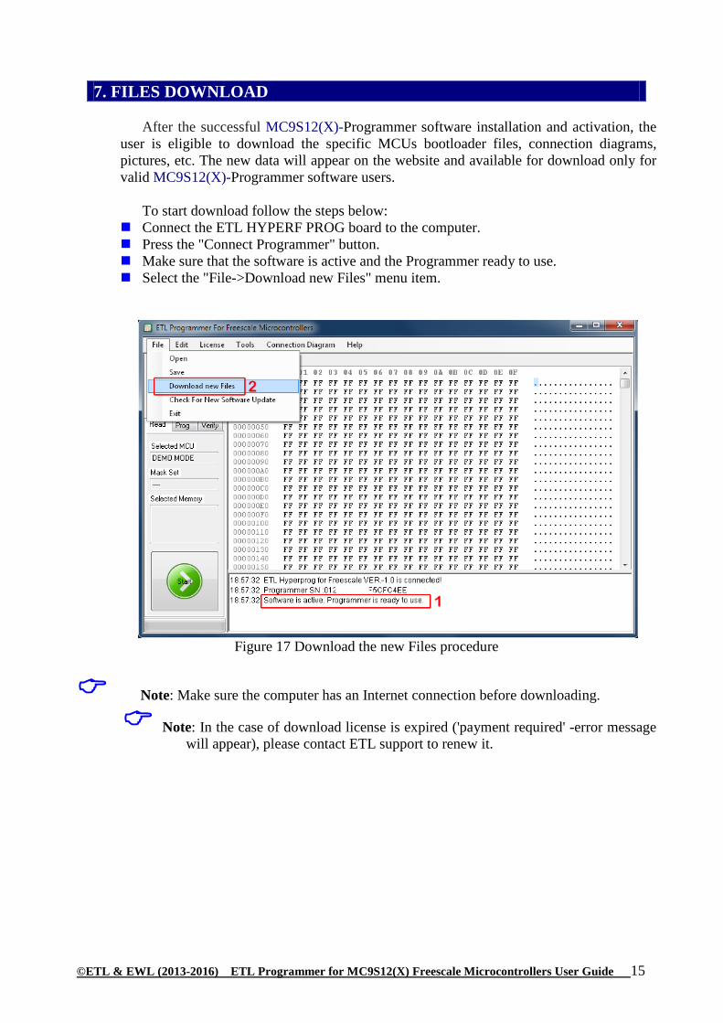
7. FILES DOWNLOAD
After the successful MC9S12(X)-Programmer software installation and activation, the
user is eligible to download the specific MCUs bootloader files, connection diagrams, pictures, etc. The new data will appear on the website and available for download only for valid MC9S12(X)-Programmer software users.
To start download follow the steps below:
Connect the ETL HYPERF PROG board to the computer. Press the "Connect Programmer" button. Make sure that the software is active and the Programmer ready to use. Select the "File->Download new Files" menu item.
Figure 17 Download the new Files procedure
Note: Make sure the computer has an Internet connection before downloading.
Note: In the case of download license is expired ('payment required' -error message will appear), please contact ETL support to renew it.

©ETL & EWL (2013-2016) ETL Programmer for MC9S12(X) Freescale Microcontrollers User Guide 16
8. CAS4 MC9S12XEP100 (5M48H) PRACTICE
This section describes the steps needed to read D-FLASH and P-FLASH memories
from the secure MC9S12XEP100 (5M48H) microcontroller. Because of the MCU security, the “On-Board” method must be used with the adapter. Please follow these steps:
Assembly the MC9S12XE 144LQFP adapter board (Figure 18). The board and all parts
for assembly provided by ETL.
Note: Installation of all resistors and capacitors is mandatory. Otherwise, the adapter will not operate correctly.
Figure 18 MC9S12XE 144LQFP assembled adapter board
Solder MC9S12XEP100 MCU on the adapter concerning 1-st pin location (Figure 18).
Note: After MCU installation, make sure there are no shorted pins on the MCU and the adapter board. The MC9S12(X)-Programmer 'Pin Tester ' is not able to detect the shorted pins. To spot the shorted pins use an inspection microscope (Figure 19).
Note: The MC9S12(X)-Programmer 'Pin Tester' can detect unconnected pin(s). The corresponding undetected pin will show in the LOG Window. The 'Pin Tester' can be disabled in the MC9S12(X)-Programmer "Options" menu tab.

©ETL & EWL (2013-2016) ETL Programmer for MC9S12(X) Freescale Microcontrollers User Guide 17
Figure 19 Using Inspection Microscope to control soldering quality
Insert adapter board into the MC9S12(X)-Programmer concerning 1-st pin locations
(Figure 20).
Figure 20 Proper adapter board insertion

©ETL & EWL (2013-2016) ETL Programmer for MC9S12(X) Freescale Microcontrollers User Guide 18
Execute the MC9S12(X)-Programmer software. Connect the ETL HYPERF PROG by
pressing 'Connect Programmer' button. Make sure the Programmer is 'ready to use'. Select target device MC9S12XEP100 (5M48H) (Figure 21).
Figure 21 Select target device MC9S12XEP100 (5M48H)
Execute FLASH read procedure by pressing the 'Start' button (Figure 22).
Figure 22 Read Procedure execution

©ETL & EWL (2013-2016) ETL Programmer for MC9S12(X) Freescale Microcontrollers User Guide 19
Wait until 'Reading is Completed Successfully' appears. The device read process includes three main steps (Figure 23): 1) Security Bypass. This step may take from 1 to 60 seconds. 2) Data FLASH Read. This action must not take more than 1-2 seconds. 3) Program FLASH Read. This stage must take not more than two minutes.
Note: If any of these steps take longer than expected, it is possible to interrupt the procedure by pressing the 'Start/Cancel' Button.
Figure 23 Read Procedure completed Successfully
Save memory data (dump) to a file (Figure 24).
Figure 24 Save memory data (dump) to a file
©ETL & EWL (2013-2016) ETL Programmer for MC9S12(X) Freescale Microcontrollers User Guide 20
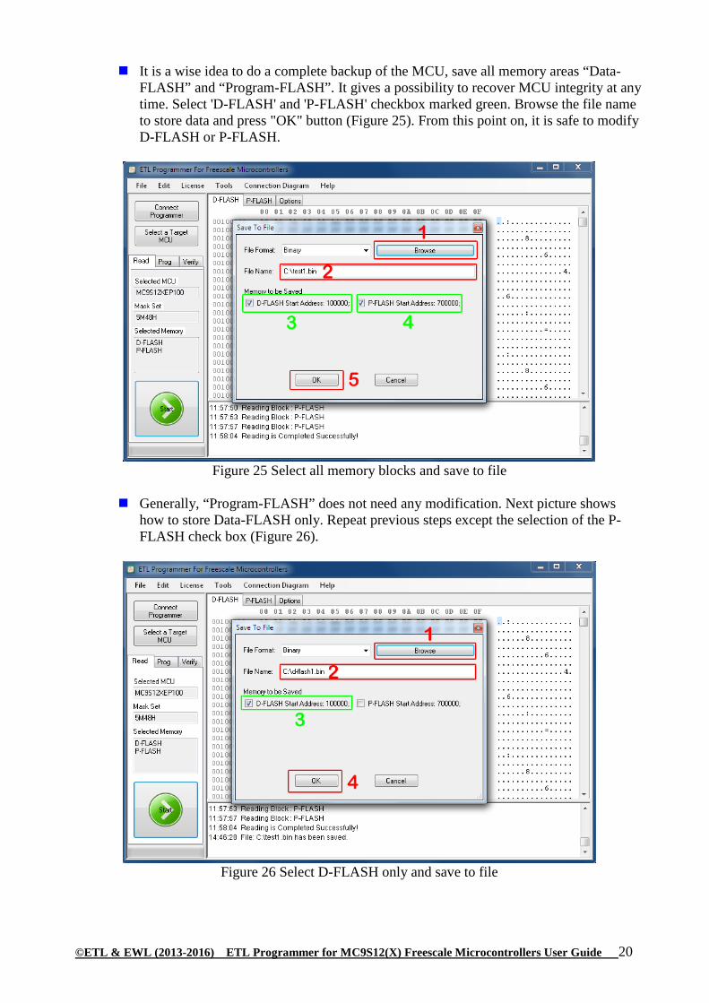
It is a wise idea to do a complete backup of the MCU, save all memory areas “Data-FLASH” and “Program-FLASH”. It gives a possibility to recover MCU integrity at any time. Select 'D-FLASH' and 'P-FLASH' checkbox marked green. Browse the file name to store data and press "OK" button (Figure 25). From this point on, it is safe to modify D-FLASH or P-FLASH.
Figure 25 Select all memory blocks and save to file
Generally, “Program-FLASH” does not need any modification. Next picture shows
how to store Data-FLASH only. Repeat previous steps except the selection of the P-FLASH check box (Figure 26).
Figure 26 Select D-FLASH only and save to file

©ETL & EWL (2013-2016) ETL Programmer for MC9S12(X) Freescale Microcontrollers User Guide 21
For example, stored Data-FLASH can be decrypted and edited by 'Free Car Calculator' software (https://etlweb.net/free-car-calculator). Select 'Dash->BMW->CAS4’ of P-FLASH check box (Figure 27). Select File->Open HEX File' menu item.
Figure 27 ETL Free Car Calculator https://etlweb.net/free-car-calculator
Press ‘Read’ Button on the main panel to make sure mileage is correct Press ‘Reset to 0’ Button to set mileage to 0. Save corrected file by the 'Save HEX File’ File menu item.

©ETL & EWL (2013-2016) ETL Programmer for MC9S12(X) Freescale Microcontrollers User Guide 22
Note: The Data-FLASH can be viewed and edited in MC9S12(X)-Programmer 'hex editor' window. Figure 29 shows the same data as decoded by 'BMW Explorer'.
Figure 29 Data-FLASH memory dump
The next step is to program the Data-FLASH back to the MCU. Select 'Open File' from
the 'File' menu. Choose file name to be loaded by 'Browse' button and press 'OK' button (Figure 30).
Figure 30 Load Data-FLASH from file

©ETL & EWL (2013-2016) ETL Programmer for MC9S12(X) Freescale Microcontrollers User Guide 23
Make sure the new file loaded successfully. Select 'Prog' tab and press the 'Start' button
(Figure 31). Shortly, D-FLASH programming will be completed.
Figure 31 Program new Data-FLASH
The last step is critical; disconnect the power from the MC9S12XEP100 MCU. To do
this press 'Power OFF' button located on the ETL HYPERF PROG (Figure 32).
Please always disconnect the power of target MCU by pressing the 'Power OFF' button.
Note: Removing On-board adapter with power connected may damage target MCU or/and HYPERF PROG itself!
Figure 32 Power OFF Button

©ETL & EWL (2013-2016) ETL Programmer for MC9S12(X) Freescale Microcontrollers User Guide 24
9. WARRANTY STATEMENT
ETL guarantees all delivered products for 60 days from registration date against manufactory
defects.