Embed Size (px)
Citation preview
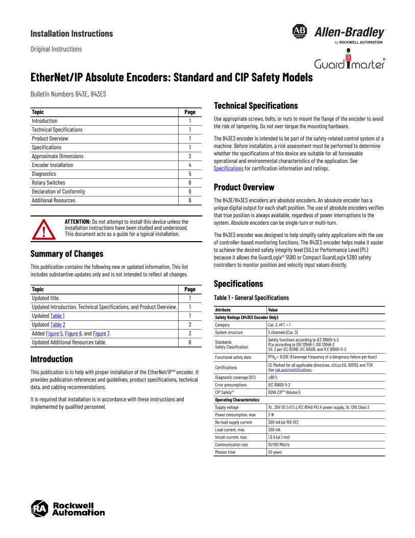
Installation InstructionsOriginal Instructions
EtherNet/IP Absolute Encoders: Standard and CIP Safety ModelsBulletin Numbers 843E, 843ES
Summary of ChangesThis publication contains the following new or updated information. This list includes substantive updates only and is not intended to reflect all changes.
IntroductionThis publication is to help with proper installation of the EtherNet/IP™ encoder. It provides publication references and guidelines, product specifications, technical data, and cabling recommendations.
It is required that installation is in accordance with these instructions and implemented by qualified personnel.
Technical SpecificationsUse appropriate screws, bolts, or nuts to mount the flange of the encoder to avoid the risk of tampering. Do not over torque the mounting hardware.
The 843ES encoder is intended to be part of the safety-related control system of a machine. Before installation, a risk assessment must be performed to determine whether the specifications of this device are suitable for all foreseeable operational and environmental characteristics of the application. See Specifications for certification information and ratings.
Product OverviewThe 843E/843ES encoders are absolute encoders. An absolute encoder has a unique digital output for each shaft position. The use of absolute encoders verifies that true position is always available, regardless of power interruptions to the system. Absolute encoders can be single-turn or multi-turn.
The 843ES encoder was designed to help simplify safety applications with the use of controller-based monitoring functions. The 843ES encoder helps make it easier to achieve the desired safety integrity level (SIL) or Performance Level (PL) because it allows the GuardLogix® 5580 or Compact GuardLogix 5380 safety controllers to monitor position and velocity input values directly.
Specifications
Topic PageIntroduction 1Technical Specifications 1Product Overview 1Specifications 1Approximate Dimensions 2Encoder Installation 4Diagnostics 5Rotary Switches 6Declaration of Conformity 6Additional Resources 6
ATTENTION: Do not attempt to install this device unless the installation instructions have been studied and understood. This document acts as a guide for a typical installation.
Topic PageUpdated title. 1Updated Introduction, Technical Specifications, and Product Overview. 1Updated Table 1 1Updated Table 2 2Added Figure 5, Figure 6, and Figure 7. 3Updated Additional Resources table. 6
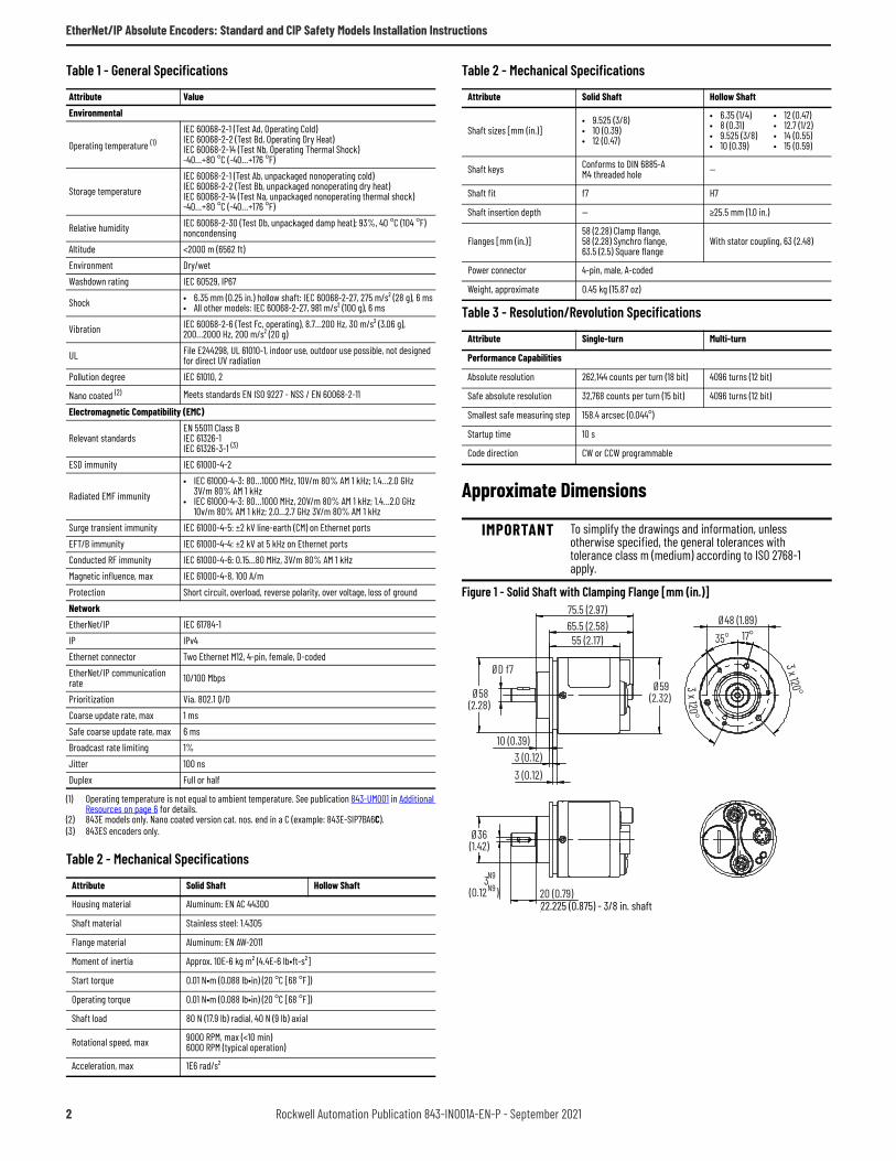
Table 1 - General Specifications
Attribute ValueSafety Ratings (843ES Encoder Only)Category Cat. 3, HFT = 1System structure 2 channels (Cat. 3)
StandardsSafety Classification
Safety functions according to IEC 61800-5-2PLe according to ISO 13849-1, ISO 13849-2SIL 3 per IEC 62061, IEC 61508, and IEC 61800-5-2
Functional safety data PFHd = 8.03E-9 (average frequency of a dangerous failure per hour)
Certifications CE Marked for all applicable directives, cULus (UL 61010), and TÜV. See rok.auto/certifications.
Diagnostic coverage (DC) ≥99%Error presumptions IEC 61800-5-2CIP Safety™ ODVA CIP™ Volume 5Operating CharacteristicsSupply voltage 10…30V DC (±5%), IEC 61140 PELV power supply, UL 1310 Class 2Power consumption, max 3 WNo-load supply current 300 mA (at 10V DC)Load current, max 300 mAInrush current, max 1.5 A (at 1 ms)Communication rate 10/100 Mbit/sMission time 20 years
EtherNet/IP Absolute Encoders: Standard and CIP Safety Models Installation Instructions
Approximate Dimensions
Figure 1 - Solid Shaft with Clamping Flange [mm (in.)]
Environmental
Operating temperature (1)IEC 60068-2-1 (Test Ad, Operating Cold)IEC 60068-2-2 (Test Bd, Operating Dry Heat)IEC 60068-2-14 (Test Nb, Operating Thermal Shock)-40…+80 °C (-40…+176 °F)
Storage temperatureIEC 60068-2-1 (Test Ab, unpackaged nonoperating cold)IEC 60068-2-2 (Test Bb, unpackaged nonoperating dry heat)IEC 60068-2-14 (Test Na, unpackaged nonoperating thermal shock)-40…+80 °C (-40…+176 °F)
Relative humidity IEC 60068-2-30 (Test Db, unpackaged damp heat); 93%, 40 °C (104 °F) noncondensing
Altitude <2000 m (6562 ft)Environment Dry/wetWashdown rating IEC 60529, IP67
Shock • 6.35 mm (0.25 in.) hollow shaft: IEC 60068-2-27, 275 m/s² (28 g), 6 ms• All other models: IEC 60068-2-27, 981 m/s² (100 g), 6 ms
Vibration IEC 60068-2-6 (Test Fc, operating), 8.7…200 Hz, 30 m/s² (3.06 g), 200…2000 Hz, 200 m/s² (20 g)
UL File E244298, UL 61010-1, indoor use, outdoor use possible, not designed for direct UV radiation
Pollution degree IEC 61010, 2
Nano coated (2) Meets standards EN ISO 9227 - NSS / EN 60068-2-11
Electromagnetic Compatibility (EMC)
Relevant standardsEN 55011 Class BIEC 61326-1IEC 61326-3-1 (3)
ESD immunity IEC 61000-4-2
Radiated EMF immunity• IEC 61000-4-3: 80…1000 MHz, 10V/m 80% AM 1 kHz; 1.4…2.0 GHz
3V/m 80% AM 1 kHz• IEC 61000-4-3: 80…1000 MHz, 20V/m 80% AM 1 kHz; 1.4…2.0 GHz
10v/m 80% AM 1 kHz; 2.0…2.7 GHz 3V/m 80% AM 1 kHzSurge transient immunity IEC 61000-4-5: ±2 kV line-earth (CM) on Ethernet portsEFT/B immunity IEC 61000-4-4: ±2 kV at 5 kHz on Ethernet portsConducted RF immunity IEC 61000-4-6: 0.15…80 MHz, 3V/m 80% AM 1 kHzMagnetic influence, max IEC 61000-4-8, 100 A/mProtection Short circuit, overload, reverse polarity, over voltage, loss of groundNetworkEtherNet/IP IEC 61784-1IP IPv4Ethernet connector Two Ethernet M12, 4-pin, female, D-codedEtherNet/IP communication rate 10/100 Mbps
Prioritization Via. 802.1 Q/DCoarse update rate, max 1 msSafe coarse update rate, max 6 msBroadcast rate limiting 1%Jitter 100 nsDuplex Full or half
(1) Operating temperature is not equal to ambient temperature. See publication 843-UM001 in Additional Resources on page 6 for details.
(2) 843E models only. Nano coated version cat. nos. end in a C (example: 843E-SIP7BA6C).(3) 843ES encoders only.
Table 2 - Mechanical Specifications
Attribute Solid Shaft Hollow Shaft
Housing material Aluminum: EN AC 44300
Shaft material Stainless steel: 1.4305
Flange material Aluminum: EN AW-2011
Moment of inertia Approx. 10E-6 kg m² (4.4E-6 lb•ft-s²]
Start torque 0.01 N•m (0.088 lb•in) (20 °C [68 °F])
Operating torque 0.01 N•m (0.088 lb•in) (20 °C [68 °F])
Shaft load 80 N (17.9 lb) radial, 40 N (9 lb) axial
Rotational speed, max 9000 RPM, max (<10 min)6000 RPM (typical operation)
Acceleration, max 1E6 rad/s²
Table 1 - General Specifications
Attribute Value
Shaft sizes [mm (in.)]• 9.525 (3/8)• 10 (0.39)• 12 (0.47)
• 6.35 (1/4)• 8 (0.31)• 9.525 (3/8)• 10 (0.39)
• 12 (0.47)• 12.7 (1/2)• 14 (0.55)• 15 (0.59)
Shaft keys Conforms to DIN 6885-AM4 threaded hole —
Shaft fit f7 H7
Shaft insertion depth — ≥25.5 mm (1.0 in.)
Flanges [mm (in.)]58 (2.28) Clamp flange,58 (2.28) Synchro flange,63.5 (2.5) Square flange
With stator coupling, 63 (2.48)
Power connector 4-pin, male, A-coded
Weight, approximate 0.45 kg (15.87 oz)
Table 3 - Resolution/Revolution Specifications
Attribute Single-turn Multi-turn
Performance Capabilities
Absolute resolution 262,144 counts per turn (18 bit) 4096 turns (12 bit)
Safe absolute resolution 32,768 counts per turn (15 bit) 4096 turns (12 bit)
Smallest safe measuring step 158.4 arcsec (0.044°)
Startup time 10 s
Code direction CW or CCW programmable
IMPORTANT To simplify the drawings and information, unless otherwise specified, the general tolerances with tolerance class m (medium) according to ISO 2768-1 apply.
Table 2 - Mechanical Specifications
Attribute Solid Shaft Hollow Shaft
75.5 (2.97)
55 (2.17)65.5 (2.58)
10 (0.39)3 (0.12)3 (0.12)
Ø59(2.32) Ø58
(2.28)
Ø48 (1.89)35° 17°
3 x 120°3 x 120°
20 (0.79)3
(0.12 )N9N9
Ø36(1.42)
ØD f7
22.225 (0.875) - 3/8 in. shaft22.225 (0.875) - 3/8 in. shaft
2 Rockwell Automation Publication 843-IN001A-EN-P - September 2021
EtherNet/IP Absolute Encoders: Standard and CIP Safety Models Installation Instructions
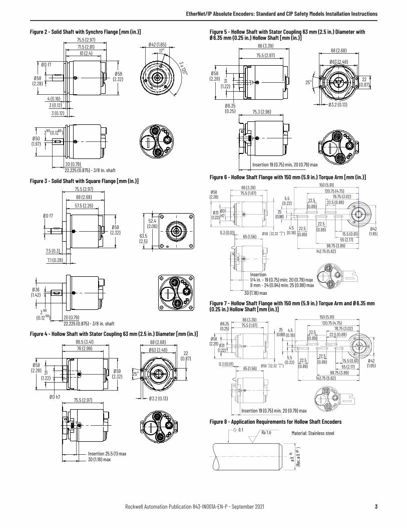
Figure 2 - Solid Shaft with Synchro Flange [mm (in.)]
Figure 3 - Solid Shaft with Square Flange [mm (in.)]
Figure 4 - Hollow Shaft with Stator Coupling 63 mm (2.5 in.) Diameter [mm (in.)]
Figure 5 - Hollow Shaft with Stator Coupling 63 mm (2.5 in.) Diameter with Ø6.35 mm (0.25 in.) Hollow Shaft [mm (in.)]
Figure 6 - Hollow Shaft Flange with 150 mm (5.9 in.) Torque Arm [mm (in.)]
Figure 7 - Hollow Shaft Flange with 150 mm (5.9 in.) Torque Arm and Ø6.35 mm (0.25 in.) Hollow Shaft [mm (in.)]
Figure 8 - Application Requirements for Hollow Shaft Encoders
75.5 (2.97)71.5 (2.81)
3 (0.12)4 (0.16)
61 (2.4)
3 (0.12)
ØD f7
Ø59(2.32)Ø58
(2.28)
3 x 120°
17°Ø42 (1.65)
20 (0.79)
3 (0.12 ) N9
Ø50(1.97)
N9
22.225 (0.875) - 3/8 in. shaft22.225 (0.875) - 3/8 in. shaft
7.5 (0.3)
7.1 (0.28)
75.5 (2.97)
57.5 (2.26)68 (2.68)
ØD f7
Ø59(2.32)
52.4(2.06)
63.5(2.5)
20 (0.79)
Ø36(1.42)
3 (0.12 ) N9
N9
22.225 (0.875) - 3/8 in. shaft22.225 (0.875) - 3/8 in. shaft
ØD h7
76 (2.99)86.5 (3.41)
Ø59(2.32)
Ø58(2.28) 31
(1.22)25°
22(0.87)
Ø3.2 (0.13)
68 (2.68)Ø63 (2.48)
75.5 (2.97)
Insertion 25.5 (1) max30 (1.18) max
86 (3.39)
75.5 (2.97)
Ø6.35(0.25)
Ø63 (2.48)
25° 22(0.87)
Ø3.2 (0.13)
Ø58(2.28) 31
(1.22)
68 (2.68)
75.3 (2.96)
Insertion 19 (0.75) min, 20 (0.79) max
86 (3.39)75.5 (1.97)
150 (5.91)120.75 (4.75)
76.75 (3.02)Ø58
(2.28)
Ø31(1.22)
ØDH7
Ø59 (2.32 )+10
+0.0400.3 (0.01)
65 (1.56)
5.5(0.22)
4.5(0.18)
22.5(0.89)
22.5(0.89)
22.5(0.89)
22.5 (0.89)
Ø42(1.65)15.5 (0.61)
55 (2.17)98.75 (3.89)
142.75 (5.62)
25(0.98)
Insertion1/4 in. - 19 (0.75) min; 20 (0.79) max8 mm - 24 (0.94) min; 25 (0.98) max
30 (1.18) max
86 (3.39)75.5 (1.97)
150 (5.91)120.75 (4.75)
76.75 (3.02)Ø6.35(0.25)
Ø59 (2.32 )+10
+0.040
0.3 (0.01)65 (1.56)
5.5(0.22)
4.5(0.18)
22.5(0.89)
22.5(0.89)
22.5(0.89)
22.5 (0.89)
Ø42(1.65)
15.5 (0.61)55 (2.17)
98.75 (3.89)142.75 (5.62)
25(0.98)
Ø31(1.22)
Ø58(2.28)
Insertion 19 (0.75) min, 20 (0.79) max
0.1 Ra 1.6
ø X f6
(Rec
. ø X
g6 )
Material: Stainless steel
Rockwell Automation Publication 843-IN001A-EN-P - September 2021 3
EtherNet/IP Absolute Encoders: Standard and CIP Safety Models Installation Instructions
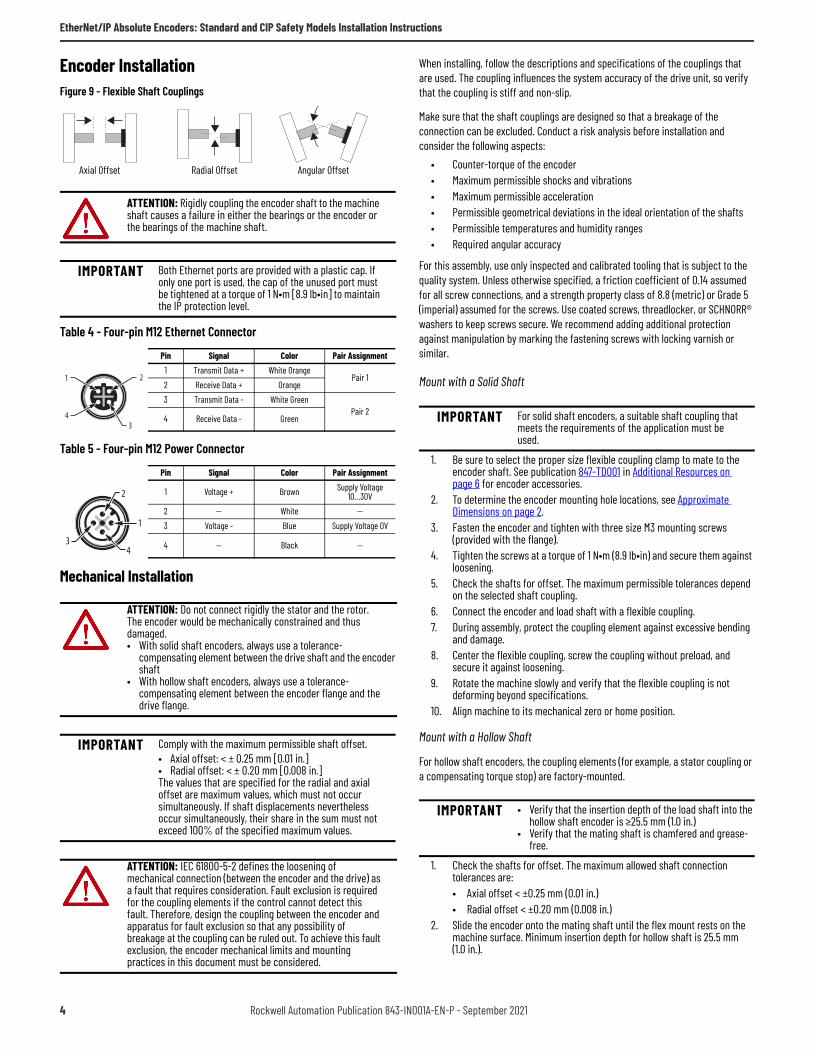
Encoder InstallationFigure 9 - Flexible Shaft Couplings
Mechanical Installation
When installing, follow the descriptions and specifications of the couplings that are used. The coupling influences the system accuracy of the drive unit, so verify that the coupling is stiff and non-slip.
Make sure that the shaft couplings are designed so that a breakage of the connection can be excluded. Conduct a risk analysis before installation and consider the following aspects:
• Counter-torque of the encoder• Maximum permissible shocks and vibrations• Maximum permissible acceleration• Permissible geometrical deviations in the ideal orientation of the shafts• Permissible temperatures and humidity ranges• Required angular accuracy
For this assembly, use only inspected and calibrated tooling that is subject to the quality system. Unless otherwise specified, a friction coefficient of 0.14 assumed for all screw connections, and a strength property class of 8.8 (metric) or Grade 5 (imperial) assumed for the screws. Use coated screws, threadlocker, or SCHNORR® washers to keep screws secure. We recommend adding additional protection against manipulation by marking the fastening screws with locking varnish or similar.
Mount with a Solid Shaft
1. Be sure to select the proper size flexible coupling clamp to mate to the encoder shaft. See publication 847-TD001 in Additional Resources on page 6 for encoder accessories.
2. To determine the encoder mounting hole locations, see Approximate Dimensions on page 2.
3. Fasten the encoder and tighten with three size M3 mounting screws (provided with the flange).
4. Tighten the screws at a torque of 1 N•m (8.9 lb•in) and secure them against loosening.
5. Check the shafts for offset. The maximum permissible tolerances depend on the selected shaft coupling.
6. Connect the encoder and load shaft with a flexible coupling.7. During assembly, protect the coupling element against excessive bending
and damage.8. Center the flexible coupling, screw the coupling without preload, and
secure it against loosening.9. Rotate the machine slowly and verify that the flexible coupling is not
deforming beyond specifications.10. Align machine to its mechanical zero or home position.
Mount with a Hollow Shaft
For hollow shaft encoders, the coupling elements (for example, a stator coupling or a compensating torque stop) are factory-mounted.
1. Check the shafts for offset. The maximum allowed shaft connection tolerances are:• Axial offset < ±0.25 mm (0.01 in.)• Radial offset < ±0.20 mm (0.008 in.)
2. Slide the encoder onto the mating shaft until the flex mount rests on the machine surface. Minimum insertion depth for hollow shaft is 25.5 mm (1.0 in.).
ATTENTION: Rigidly coupling the encoder shaft to the machine shaft causes a failure in either the bearings or the encoder or the bearings of the machine shaft.
IMPORTANT Both Ethernet ports are provided with a plastic cap. If only one port is used, the cap of the unused port must be tightened at a torque of 1 N•m [8.9 lb•in] to maintain the IP protection level.
Table 4 - Four-pin M12 Ethernet Connector
Pin Signal Color Pair Assignment1 Transmit Data + White Orange
Pair 12 Receive Data + Orange3 Transmit Data - White Green
Pair 24 Receive Data - Green
Table 5 - Four-pin M12 Power Connector
Pin Signal Color Pair Assignment
1 Voltage + Brown Supply Voltage 10…30V
2 — White —3 Voltage - Blue Supply Voltage 0V
4 — Black —
ATTENTION: Do not connect rigidly the stator and the rotor. The encoder would be mechanically constrained and thus damaged.• With solid shaft encoders, always use a tolerance-
compensating element between the drive shaft and the encoder shaft
• With hollow shaft encoders, always use a tolerance-compensating element between the encoder flange and the drive flange.
IMPORTANT Comply with the maximum permissible shaft offset.• Axial offset: < ± 0.25 mm [0.01 in.]• Radial offset: < ± 0.20 mm [0.008 in.]The values that are specified for the radial and axial offset are maximum values, which must not occur simultaneously. If shaft displacements nevertheless occur simultaneously, their share in the sum must not exceed 100% of the specified maximum values.
ATTENTION: IEC 61800-5-2 defines the loosening of mechanical connection (between the encoder and the drive) as a fault that requires consideration. Fault exclusion is required for the coupling elements if the control cannot detect this fault. Therefore, design the coupling between the encoder and apparatus for fault exclusion so that any possibility of breakage at the coupling can be ruled out. To achieve this fault exclusion, the encoder mechanical limits and mounting practices in this document must be considered.
Axial Offset Radial Offset Angular Offset
1 2
34
2
1
34
IMPORTANT For solid shaft encoders, a suitable shaft coupling that meets the requirements of the application must be used.
IMPORTANT • Verify that the insertion depth of the load shaft into the hollow shaft encoder is ≥25.5 mm (1.0 in.)
• Verify that the mating shaft is chamfered and grease-free.
4 Rockwell Automation Publication 843-IN001A-EN-P - September 2021
EtherNet/IP Absolute Encoders: Standard and CIP Safety Models Installation Instructions
3. Hold encoder firmly and mark the two mounting holes. (If mounting holes exist, proceed to step 6.)
4. Slide the encoder off. To accept M3 (or equivalent) screws, drill and tap the marked holes.
5. Slide the encoder back onto the shaft until the flex mount rests on the machine surface.
6. Attach the encoder with two M3 (or equivalent) screws. Screw the stator coupling and the torque stop without preload on the drive flange. Tighten the screws to 1 N•m [8.9 lb•in].
7. Tighten the clamping ring screw to 2.5 N•m (22.1 lb•in).8. Align machine to its mechanical zero or home position.
Electrical Installation
Route the encoder cable free of any tension, so that no additional force is applied to the encoder. Consider the minimum bending radius of the connection cable.
Connectivity Considerations
Consider using the shortest length possible for both Ethernet and power cables. Run Ethernet cables separate from power cables and run the DC power cable away from AC power.
Verify that no other devices with high interference levels such as frequency converters, solenoid valves, or contactors, are connected to the same power supply as the encoder. Otherwise, use suitable voltage filtering.
We recommend shielded twisted-pair cables for both Ethernet and power connections. These cables help avoid disruptions of signals from electrical noise and from mechanical vibration and shock that are common in most industrial environments. When installing the shielded cables, you must follow the recommended installation guidelines to avoid ground loops. You must comply with the maximum permissible connection cable length.
For shielded Ethernet cables, you must provide an equipotential grounding network that overlays the existing electrical grounding and bonding system for safety and fire. If you cannot provide an equipotential ground and the second connection from the encoder is going to a switch, install a patch panel to break the shield to the switch. Switches typically connect jack shield directly to the ground lug, which connects the shield directly to ground.
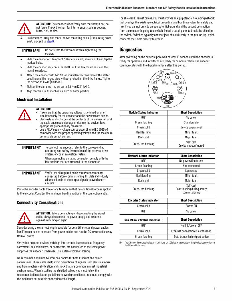
DiagnosticsAfter switching on the power supply, wait at least 10 seconds until the encoder is ready for operation and interfaces are ready for communication. The encoder communicates with the digital interface after this period.
ATTENTION: The encoder slides freely onto the shaft; if not, do not force. Check the shaft for interferences such as gouges, burrs, rust, or size.
IMPORTANT Do not stress the flex mount while tightening the screws.
ATTENTION: • Make sure that the operating voltage is switched on or off
simultaneously for the encoder and the downstream device.• Electrostatic discharges at the contacts of the connector or at
the cable ends could damage or destroy the device. Take appropriate precautionary measures.
• Use a PELV supply voltage source according to IEC 60204-1 complying with the proper operating voltage and the maximum permissible output current.
IMPORTANT To connect the encoder, refer to the corresponding operating and safety instructions of the external drive system/encoder evaluation system.When assembling a mating connector, comply with the instructions that are attached to the connector.
IMPORTANT Verify that all required cable wires/connectors are connected before commissioning. Insulate individually all unused ends of the output signals to avoid short-circuits.
ATTENTION: Before connecting or disconnecting the signal cable, always disconnect the power supply and secure it against switching on again.
Module Status Indicator Short DescriptionOFF No power
Green flashing Standby/idleGreen solid Device operational
Red flashing Minor faultRed solid Major fault
Green/red flashing Self-testDevice not configured
Network Status Indicator Short DescriptionOFF No power/IP address
Green flashing Not connectedGreen solid Connected
Red flashing Minor faultRed solid Major fault
Green/red flashingSelf-test
Fast flashing during safety commissioning
Encoder Status Indicator Short DescriptionGreen solid Power ON
OFF No power
Link 1/Link 2 Status Indicator (1)
(1) The Ethernet link status indicators (Link 1 and Link 2) display the status of the physical connection on the Ethernet interface.
Short Description
OFF No link/power OFFGreen solid Ethernet connection is established
Green flashing Data transmission/port active
Net. Encoder
Mod.Link 1 GND
Port 1
x100
x10
x1
10…30V DC Link 2
Port 2
Rockwell Automation Publication 843-IN001A-EN-P - September 2021 5
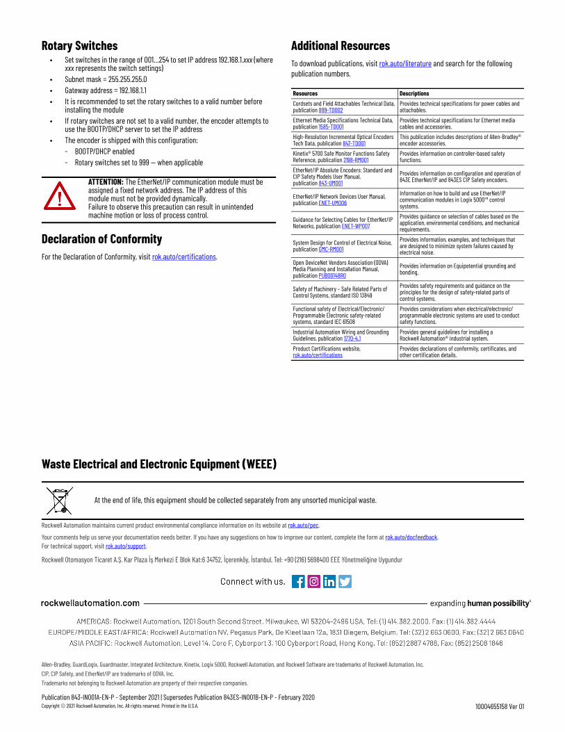
Rotary Switches• Set switches in the range of 001…254 to set IP address 192.168.1.xxx (where
xxx represents the switch settings)• Subnet mask = 255.255.255.0• Gateway address = 192.168.1.1• It is recommended to set the rotary switches to a valid number before
installing the module• If rotary switches are not set to a valid number, the encoder attempts to
use the BOOTP/DHCP server to set the IP address• The encoder is shipped with this configuration:
- BOOTP/DHCP enabled- Rotary switches set to 999 — when applicable
Declaration of ConformityFor the Declaration of Conformity, visit rok.auto/certifications.
Additional ResourcesTo download publications, visit rok.auto/literature and search for the following publication numbers.
ATTENTION: The EtherNet/IP communication module must be assigned a fixed network address. The IP address of this module must not be provided dynamically.Failure to observe this precaution can result in unintended machine motion or loss of process control.
Resources DescriptionsCordsets and Field Attachables Technical Data, publication 889-TD002
Provides technical specifications for power cables and attachables.
Ethernet Media Specifications Technical Data, publication 1585-TD001
Provides technical specifications for Ethernet media cables and accessories.
High-Resolution Incremental Optical Encoders Tech Data, publication 847-TD001
This publication includes descriptions of Allen-Bradley® encoder accessories.
Kinetix® 5700 Safe Monitor Functions Safety Reference, publication 2198-RM001
Provides information on controller-based safety functions.
EtherNet/IP Absolute Encoders: Standard and CIP Safety Models User Manual, publication 843-UM001
Provides information on configuration and operation of 843E EtherNet/IP and 843ES CIP Safety encoders.
EtherNet/IP Network Devices User Manual, publication ENET-UM006
Information on how to build and use EtherNet/IP communication modules in Logix 5000™ control systems.
Guidance for Selecting Cables for EtherNet/IP Networks, publication ENET-WP007
Provides guidance on selection of cables based on the application, environmental conditions, and mechanical requirements.
System Design for Control of Electrical Noise, publication GMC-RM001
Provides information, examples, and techniques that are designed to minimize system failures caused by electrical noise.
Open DeviceNet Vendors Association (ODVA) Media Planning and Installation Manual, publication PUB00148R0
Provides information on Equipotential grounding and bonding.
Safety of Machinery – Safe Related Parts of Control Systems, standard ISO 13849
Provides safety requirements and guidance on the principles for the design of safety-related parts of control systems.
Functional safety of Electrical/Electronic/Programmable Electronic safety-related systems, standard IEC 61508
Provides considerations when electrical/electronic/programmable electronic systems are used to conduct safety functions.
Industrial Automation Wiring and Grounding Guidelines, publication 1770-4.1
Provides general guidelines for installing a Rockwell Automation® industrial system.
Product Certifications website, rok.auto/certifications
Provides declarations of conformity, certificates, and other certification details.
Publication 843-IN001A-EN-P - September 2021 | Supersedes Publication 843ES-IN001B-EN-P - February 2020Copyright © 2021 Rockwell Automation, Inc. All rights reserved. Printed in the U.S.A.
Rockwell Otomasyon Ticaret A.Ş. Kar Plaza İş Merkezi E Blok Kat:6 34752, İçerenköy, İstanbul, Tel: +90 (216) 5698400 EEE Yönetmeliğine Uygundur
Allen-Bradley, GuardLogix, Guardmaster, Integrated Architecture, Kinetix, Logix 5000, Rockwell Automation, and Rockwell Software are trademarks of Rockwell Automation, Inc.CIP, CIP Safety, and EtherNet/IP are trademarks of ODVA, Inc.Trademarks not belonging to Rockwell Automation are property of their respective companies.
Your comments help us serve your documentation needs better. If you have any suggestions on how to improve our content, complete the form at rok.auto/docfeedback.For technical support, visit rok.auto/support.
10004655158 Ver 01
Waste Electrical and Electronic Equipment (WEEE)
Rockwell Automation maintains current product environmental compliance information on its website at rok.auto/pec.
At the end of life, this equipment should be collected separately from any unsorted municipal waste.

CONFIDENTIAL AND PROPRIETARY INFORMATION. THIS DOCUMENT CONTAINS CONFIDENTIAL AND PROPRIETARY INFORMATION OF
ROCKWELL AUTOMATION, INC. AND MAY NOT BE USED, COPIED OR DISCLOSED TO OTHERS, EXCEPT WITH THE AUTHORIZED WRITTEN
PERMISSION OF ROCKWELL AUTOMATION, INC.
Sheet
Size Ver
Of 11
A 0110000028320Dr. DateG. USHAKOW 8-23-13
MATERIALSIZE
FOLD
TO BE DETERMINEDBY STRATEGIC PARTNER
TO BE DETERMINEDBY STRATEGIC PARTNER
TO BE DETERMINEDBY STRATEGIC PARTNER
FLAT
SPECIFICATIONS FORINSTRUCTION SHEET CREATED BY STRATEGIC PARTNER
This Instruction Sheet is Being Printed by Strategic Partner
Note: After folding---Printed in (Country where printed*), part number(s) and barcode (when used) should be visible.
* The printing vendor may change the instruction sheet files to show the correct country.