Embed Size (px)
Citation preview
Ethernet Routing Switch
iSCSI Storage
Engineering
> Data Center iSCSI Solution Guide
Avaya Data Solutions
Document Date: November 2010
Document Number: NN48500-590
Document Version: 2.0
Avaya Inc. – External Distribution 2
avaya.com
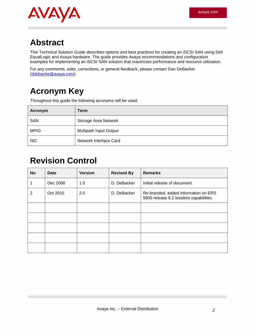
Abstract This Technical Solution Guide describes options and best practices for creating an iSCSI SAN using Dell EqualLogic and Avaya hardware. The guide provides Avaya recommendations and configuration examples for implementing an iSCSI SAN solution that maximizes performance and resource utilization.
For any comments, edits, corrections, or general feedback, please contact Dan DeBacker ([email protected]).
Acronym Key
Throughout this guide the following acronyms will be used:
Acronym Term
SAN Storage Area Network
MPIO Multipath Input Output
NIC Network Interface Card
Revision Control
No Date Version Revised By Remarks
1 Dec 2008 1.0 D. DeBacker Initial release of document
2 Oct 2010 2.0 D. DeBacker Re-branded, added information on ERS 5600 release 6.2 lossless capabilities
Avaya Inc. – External Distribution 3
avaya.com
Table of Contents 1. Introduction ............................................................................................................................................ 6
2. iSCSI SAN Fundamentals ..................................................................................................................... 7
3. iSCSI Deployment Options .................................................................................................................. 10
3.1 Single Switch Implementation ..................................................................................................... 11
3.2 Two Switch Redundancy ............................................................................................................. 14
3.3 Four Switch Redundancy and Scaling ........................................................................................ 21
3.4 Configuration – ERS 5000 Four Switch Scaling ......................................................................... 32
3.5 Configuration – ERS 5000 Two Switch Redundancy.................................................................. 33
3.6 Configuration Example – ERS 8600 Single Switch..................................................................... 34
4. Reference Documentation ................................................................................................................... 39
Avaya Inc. – External Distribution 4
avaya.com
Figures
Figure 2.1: iSCSI SAN Architecture Example ............................................................................................... 9 Figure 3.1: Single Switch iSCSI SAN .......................................................................................................... 11 Figure 3.2: ERS 55xx Single Switch – 48 Ports .......................................................................................... 12 Figure 3.3: ERS 55xx Single Switch – 24 Ports .......................................................................................... 13 Figure 3.4: ERS 5650TD Single Switch – 48 Ports .................................................................................... 13 Figure 3.5: ERS 5632FD Single Switch – 10 Gigabit ................................................................................. 14 Figure 3.6: Two Switch Redundancy iSCSI SAN........................................................................................ 14 Figure 3.7: Two Switch Redundancy Detailed Connectivity ....................................................................... 16 Figure 3.8: ERS 55xx Two Switch Redundancy – 48 Port Switch 1 ........................................................... 17 Figure 3.9: ERS 55xx Two Switch Redundancy – 48 Port Switch 2 ........................................................... 17 Figure 3.10: ERS 55xx Two Switch Redundancy – 24 Port Switch 1 ......................................................... 18 Figure 3.11: ERS 55xx Two Switch Redundancy – 24 Port Switch 2 ......................................................... 18 Figure 3.12: ERS 5650TD Two Switch Redundancy – 48 Port Switch 1 ................................................... 19 Figure 3.13: ERS 5650TD Two Switch Redundancy – 48 Port Switch 2 ................................................... 19 Figure 3.14: ERS 5632FD Two Switch Redundancy – 10 Gigabit Switch 1 ............................................... 20 Figure 3.15: ERS 5632FD Two Switch Redundancy – 10 Gigabit Switch 2 ............................................... 20 Figure 3.16: Four Switch Redundancy and Scaling .................................................................................... 21 Figure 3.17: Four Switch Redundancy and Scaling Detailed Connectivity ................................................. 23 Figure 3.18: ERS 55xx Four Switch Scaling – 48 Port Switch 1 ................................................................. 24 Figure 3.19: ERS 55xx Four Switch Scaling – 48 Port Switch 2 ................................................................. 24 Figure 3.20: ERS 55xx Four Switch Scaling – 48 Port Switch 3 ................................................................. 25 Figure 3.21: ERS 55xx Four Switch Scaling – 48 Port Switch 4 ................................................................. 25 Figure 3.22: ERS 55xx Four Switch Scaling – 24 Port Switch 1 ................................................................. 26 Figure 3.23: ERS 55xx Four Switch Scaling – 24 Port Switch 2 ................................................................. 26 Figure 3.24: ERS 55xx Four Switch Scaling – 24 Port Switch 3 ................................................................. 27 Figure 3.25: ERS 55xx Four Switch Scaling – 24 Port Switch 4 ................................................................. 27 Figure 3.26: ERS 5650TD Four Switch Scaling – 48 Port Switch 1 ........................................................... 28 Figure 3.27: ERS 5650TD Four Switch Scaling – 48 Port Switch 2 ........................................................... 28 Figure 3.28: ERS 5650TD Four Switch Scaling – 48 Port Switch 3 ........................................................... 29 Figure 3.29: ERS 5650TD Four Switch Scaling – 48 Port Switch 4 ........................................................... 29 Figure 3.30: ERS 5632FD Two Switch Redundancy – 10 Gigabit Switch 1 ............................................... 30 Figure 3.31: ERS 5632FD Two Switch Redundancy – 10 Gigabit Switch 2 ............................................... 30 Figure 3.32: ERS 5632FD Two Switch Redundancy – 10 Gigabit Switch 3 ............................................... 31 Figure 3.33: ERS 5632FD Two Switch Redundancy – 10 Gigabit Switch 4 ............................................... 31 Figure 3.34: ERS 5000 Configuration Example .......................................................................................... 32 Figure 3.35: ERS 8600 I/O Module Lanes .................................................................................................. 34 Figure 3.36: ERS 8600 Connectivity Example ............................................................................................ 36
Avaya Inc. – External Distribution 5
avaya.com
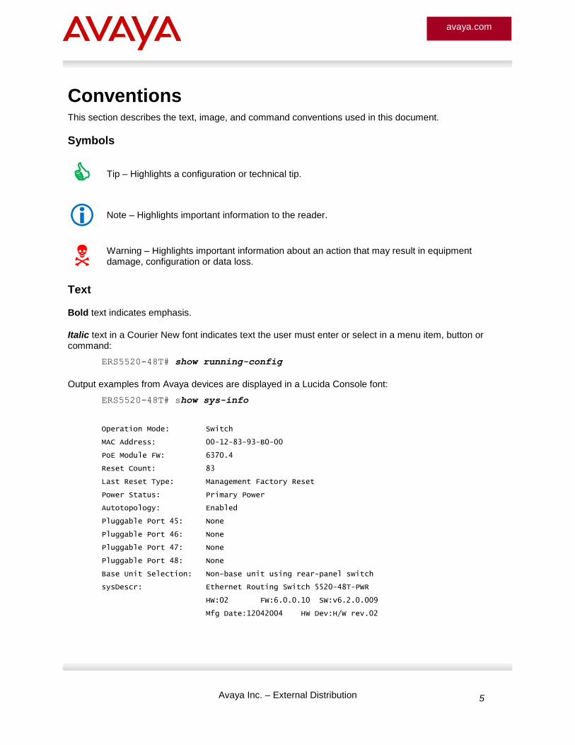
Conventions This section describes the text, image, and command conventions used in this document.
Symbols
Tip – Highlights a configuration or technical tip.
Note – Highlights important information to the reader.
Warning – Highlights important information about an action that may result in equipment damage, configuration or data loss.
Text
Bold text indicates emphasis.
Italic text in a Courier New font indicates text the user must enter or select in a menu item, button or command:
ERS5520-48T# show running-config
Output examples from Avaya devices are displayed in a Lucida Console font:
ERS5520-48T# show sys-info
Operation Mode: Switch
MAC Address: 00-12-83-93-B0-00
PoE Module FW: 6370.4
Reset Count: 83
Last Reset Type: Management Factory Reset
Power Status: Primary Power
Autotopology: Enabled
Pluggable Port 45: None
Pluggable Port 46: None
Pluggable Port 47: None
Pluggable Port 48: None
Base Unit Selection: Non-base unit using rear-panel switch
sysDescr: Ethernet Routing Switch 5520-48T-PWR
HW:02 FW:6.0.0.10 SW:v6.2.0.009
Mfg Date:12042004 HW Dev:H/W rev.02
Avaya Inc. – External Distribution 6
avaya.com
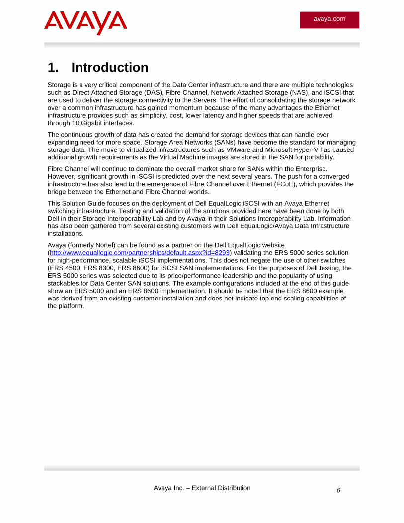
1. Introduction
Storage is a very critical component of the Data Center infrastructure and there are multiple technologies such as Direct Attached Storage (DAS), Fibre Channel, Network Attached Storage (NAS), and iSCSI that are used to deliver the storage connectivity to the Servers. The effort of consolidating the storage network over a common infrastructure has gained momentum because of the many advantages the Ethernet infrastructure provides such as simplicity, cost, lower latency and higher speeds that are achieved through 10 Gigabit interfaces.
The continuous growth of data has created the demand for storage devices that can handle ever expanding need for more space. Storage Area Networks (SANs) have become the standard for managing storage data. The move to virtualized infrastructures such as VMware and Microsoft Hyper-V has caused additional growth requirements as the Virtual Machine images are stored in the SAN for portability.
Fibre Channel will continue to dominate the overall market share for SANs within the Enterprise. However, significant growth in iSCSI is predicted over the next several years. The push for a converged infrastructure has also lead to the emergence of Fibre Channel over Ethernet (FCoE), which provides the bridge between the Ethernet and Fibre Channel worlds.
This Solution Guide focuses on the deployment of Dell EqualLogic iSCSI with an Avaya Ethernet switching infrastructure. Testing and validation of the solutions provided here have been done by both Dell in their Storage Interoperability Lab and by Avaya in their Solutions Interoperability Lab. Information has also been gathered from several existing customers with Dell EqualLogic/Avaya Data Infrastructure installations.
Avaya (formerly Nortel) can be found as a partner on the Dell EqualLogic website (http://www.equallogic.com/partnerships/default.aspx?id=8293) validating the ERS 5000 series solution for high-performance, scalable iSCSI implementations. This does not negate the use of other switches (ERS 4500, ERS 8300, ERS 8600) for iSCSI SAN implementations. For the purposes of Dell testing, the ERS 5000 series was selected due to its price/performance leadership and the popularity of using stackables for Data Center SAN solutions. The example configurations included at the end of this guide show an ERS 5000 and an ERS 8600 implementation. It should be noted that the ERS 8600 example was derived from an existing customer installation and does not indicate top end scaling capabilities of the platform.
Avaya Inc. – External Distribution 7
avaya.com
2. iSCSI SAN Fundamentals
iSCSI is a standard protocol that allows SCSI commands to be encapsulated in TCP/IP to give Servers access to storage devices over common Ethernet IP networks. iSCSI SANs provide the same benefits of Fibre Channel in terms of consolidated storage, simplified management, and simplified backup and recovery. iSCSI SANs use Ethernet rather than Fibre Channel to transport data. Ethernet is easier to deploy, manage and maintain, as well as being less expensive than Fibre Channel.
Even though iSCSI and NAS both use Ethernet and IP for transport, they are very different technologies. iSCSI differs from NAS in that iSCSI serves up a block-level access to data (a disk drive); whereas NAS serves up file level access. The choice between NAS and iSCSI is based up the needs of the user and the applications involved. NAS is a very mature technology that has been around for quite some time and is widely deployed.
The appeal of iSCSI can be seen in many ways. The overall cost of iSCSI is significantly less than that of Fibre Channel. It is also seen as a simple and easy to use technology that relies on an Ethernet infrastructure in the Data Center. The cost and simplicity advantages have created a huge market for the technology and make the implementation of a true SAN accessible to all ranges of Enterprises (Small, Medium, and Large).
iSCSI is available today in both Gigabit and 10Gigabit implementations to once again provide the flexibility and scalability required by the Enterprise customer.
The iSCSI SAN components include:
iSCSI Initiator
Dedicated NIC or multiple NICs within a server used strictly for iSCSI communication with the disk arrays across the SAN. The use of multiple initiators provides added bandwidth and redundancy for network connectivity.
iSCSI Array
Disk arrays comprised of several high capacity disks in RAID configuration. These arrays use controllers with Gigabit or 10Gigabit Ethernet interfaces for connectivity to the SAN. Multiple controllers can be installed in an array for redundancy. Dell EqualLogic offers both 3 port and 4 port controllers. For all examples used in this guide, it is assumed that 4 port controllers will be used.
Ethernet Switching Infrastructure
Standard Gigabit-capable Ethernet switches used for creating the iSCSI SAN. No special features are required to support iSCSI (hence, it’s gain in popularity); however, basic recommendations are provided later in this document to ensure a high performance SAN infrastructure.
Servers using iSCSI have in addition to their regular IP network Ethernet interfaces one or more Ethernet interfaces performing the iSCSI Initiator function. This initiator communicates between the server and the iSCSI disk array or disk array group. When using multiple iSCSI Initiator NICs, MPIO (Multipath I/O) is the technology used in lieu of any type of link aggregation (MLT, LACP, SMLT). With MPIO each initiator has its own IP and MAC address and this feature provides several load balancing options to communicate with the iSCSI storage array: 1) Least Queue Depth, 2) Round Robin, 3) Failover (active/passive). When attached to the Ethernet switches, the initiators are connected as normal access ports with no special link aggregation or routing configuration necessary.
Multiple disk arrays may be members of an MPIO group. The MPIO group has a single group IP address. Each member of a group also has several individual IP addresses assigned. The single Group IP is the address used in communicating with the servers. The iSCSI Initiator software in the servers points to the array group IP address.
Avaya Inc. – External Distribution 8
avaya.com
EqualLogic disk arrays may have one or two controllers (two controllers are typically recommended for redundancy), providing an active/standby failover scenario. Each array controller has several Gigabit Ethernet or 10Gigabit Ethernet interfaces, depending upon the model. Typical models have either three or four Gigabit Ethernet interfaces per controller and are connected via 1000Base-TX UTP interfaces, but also may use SFPs (Small Form Factor Pluggable) for fiber connectivity. During normal operation, the standby controller within an individual disk array is not used for connectivity; it is simply mirroring the cache. The standby controller only takes over in case the primary controller fails – it does not take over if the primary controller’s Ethernet connections become disabled. For this reason, it is imperative for a fully redundant operation that the iSCSI array is properly connected to an appropriately architected network with at least two Gigabit Ethernet switches in order to protect against network failures as well as controller failures.
iSCSI disk arrays may be configured for a number of different RAID options, including RAID 5, RAID 10 and RAID 50. Disk Volumes are broken up into 15 MB pages and the pages may be spread across multiple members in an array group. For example, volume E:\ could be spread across disk array members 1, 2 and 3 within a single iSCSI array group.
Basic recommendations for a SAN implementation include:
Separate iSCSI traffic from the LAN traffic. Ideally, choose separate switches to connect LAN ports and iSCSI ports from the Servers
Choose Ethernet switches that provide high switching capacity and stacking bandwidth
Disable Unicast storm control on Ethernet switch ports and NICs
Disable spanning tree on Ethernet switch ports connected to the Storage Arrays and iSCSI initiators – if spanning tree is required/enabled, use the Spanning Tree FastStart option which brings the port up in a forwarding state immediately
Use redundant network paths between Server and Disk Array’s to increase resiliency
The use of jumbo frames is optional for iSCSI. In most instances, jumbo frames provide a slight performance improvement of roughly 10%. The Avaya Ethernet Routing Switches support the use of jumbo frames. Ensure that all parts of the SAN (server NIC, Ethernet switch, and Array) support jumbo frames and that they are configured for correct use.
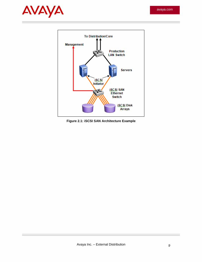
Figure 2.1 shows a simplified deployment architecture for an iSCSI SAN. There are several best practice recommendations that have been developed by both the SAN infrastructure providers and the Ethernet infrastructure providers. These best practices have been validated and tested and will help ensure a successful implementation of the SAN. Please note that these best practices are related to the infrastructure connectivity and not necessarily the architecture of the SAN itself (i.e. the partitioning of the arrays, the mapping of applications to disk, etc.). Example configurations are provided at the end of this document for the Ethernet switching infrastructure.
Avaya Inc. – External Distribution 9
avaya.com
Figure 2.1: iSCSI SAN Architecture Example
Avaya Inc. – External Distribution 10
avaya.com
3. iSCSI Deployment Options
The deployment options for iSCSI SANs vary with the requirements of the Enterprise customer. They can range from a single switch Ethernet infrastructure with no resiliency to a stacked Ethernet switch infrastructure with total resiliency and scaling capabilities. This Solution Guide will detail three different scenarios:
Single Switch
Two Switch Redundancy
Four Switch Redundancy and Scaling
In all instances, it is critical to follow the recommended configurations for best performance of the iSCSI SAN. With the Ethernet switches, there are some basic recommendations to maximize the buffer utilization of the switches and provide top performance for the iSCSI traffic. In order to make this happen, QoS queue sets and buffers need to be configured properly and the physical connectivity of the servers and arrays should be distributed as shown in each example. Following these two simple guidelines will result in a high performance infrastructure for iSCSI traffic.
There are many options for Ethernet switching infrastructure to support the iSCSI SAN. For the purpose of this guide a few of the most popular switches have been targeted for the design recommendations. Where applicable, configuration examples will be provided at the end of this guide. Ethernet Switch options include:
ERS 5000 – 5510, 5520, 5530, 5650TD, 5698TFD, 5632FD
ERS 8600 using Gigabit or 10 Gigabit I/O modules
With Release 6.2 for the ERS 5600, the QoS Lossless Mode has been added as a new feature targeted specifically for iSCSI implementations. With lossless buffering mode, when a port receives volumes of traffic greater than the port bandwidth, the port sends flow control (pause) frames to the sender. This will significantly improve data transfer reliability by nearly eliminating dropped packets due to lack of buffer space (seen as dropped on no resources within the switch).
The design/configuration rules are as follows:
Supported on ERS 5600 switches only and cannot be used in a mixed stack with ERS 5500 units.
Queue set must be 2
Stacks of up to five units are supported in layer 2 mode (no IP routing, no SMLT)
Oversubscription of 10 ingress ports to 1 egress port is supported
It is critical that all end stations connected to the switch/stack support symmetrical flow control
Avaya Inc. – External Distribution 11
avaya.com
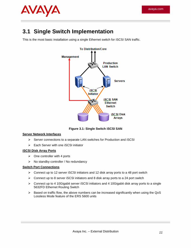
3.1 Single Switch Implementation
This is the most basic installation using a single Ethernet switch for iSCSI SAN traffic.
Figure 3.1: Single Switch iSCSI SAN
Server Network Interfaces
Server connections to a separate LAN switches for Production and iSCSI
Each Server with one iSCSI initiator
iSCSI Disk Array Ports
One controller with 4 ports
No standby controller / No redundancy
Switch Port Connections
Connect up to 12 server iSCSI initiators and 12 disk array ports to a 48 port switch
Connect up to 8 server iSCSI initiators and 8 disk array ports to a 24 port switch
Connect up to 4 10Gigabit server iSCSI initiators and 4 10Gigabit disk array ports to a single 5632FD Ethernet Routing Switch
Based on traffic flow, the above numbers can be increased significantly when using the QoS Lossless Mode feature of the ERS 5600 units
Avaya Inc. – External Distribution 12
avaya.com
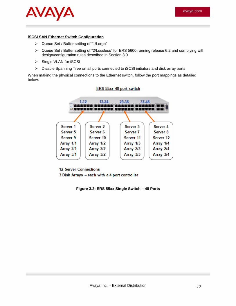
iSCSI SAN Ethernet Switch Configuration
Queue Set / Buffer setting of “1/Large”
Queue Set / Buffer setting of “2/Lossless” for ERS 5600 running release 6.2 and complying with design/configuration rules described in Section 3.0
Single VLAN for iSCSI
Disable Spanning Tree on all ports connected to iSCSI initiators and disk array ports
When making the physical connections to the Ethernet switch, follow the port mappings as detailed below:
Figure 3.2: ERS 55xx Single Switch – 48 Ports
Avaya Inc. – External Distribution 13
avaya.com
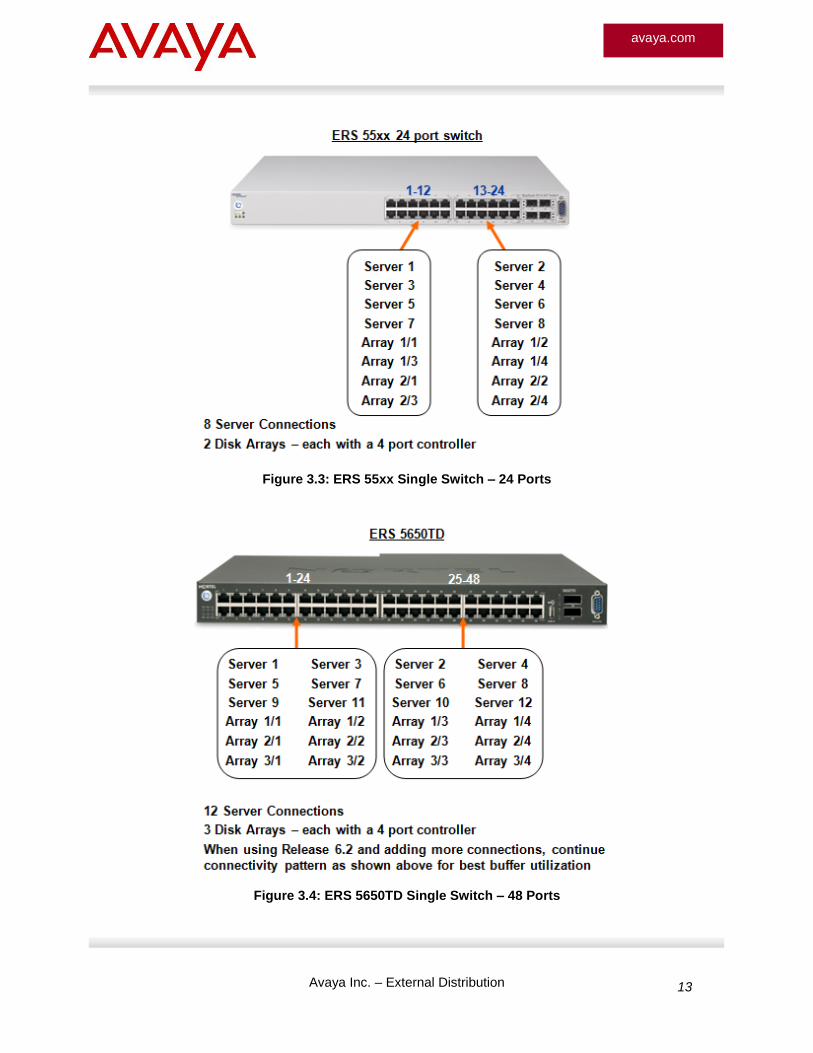
Figure 3.3: ERS 55xx Single Switch – 24 Ports
Figure 3.4: ERS 5650TD Single Switch – 48 Ports
Avaya Inc. – External Distribution 14
avaya.com
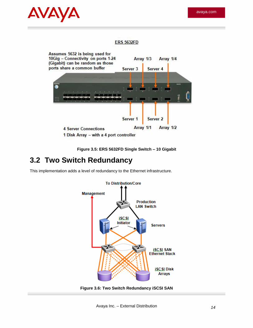
Figure 3.5: ERS 5632FD Single Switch – 10 Gigabit
3.2 Two Switch Redundancy
This implementation adds a level of redundancy to the Ethernet infrastructure.
Figure 3.6: Two Switch Redundancy iSCSI SAN
Avaya Inc. – External Distribution 15
avaya.com
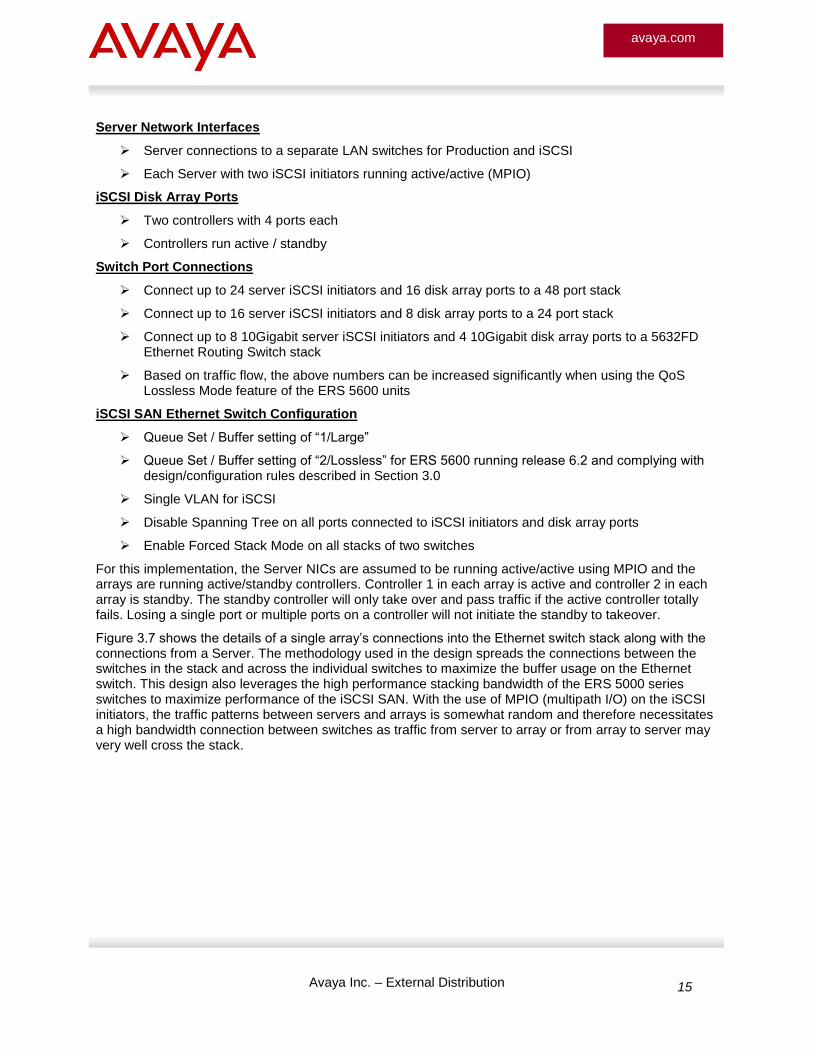
Server Network Interfaces
Server connections to a separate LAN switches for Production and iSCSI
Each Server with two iSCSI initiators running active/active (MPIO)
iSCSI Disk Array Ports
Two controllers with 4 ports each
Controllers run active / standby
Switch Port Connections
Connect up to 24 server iSCSI initiators and 16 disk array ports to a 48 port stack
Connect up to 16 server iSCSI initiators and 8 disk array ports to a 24 port stack
Connect up to 8 10Gigabit server iSCSI initiators and 4 10Gigabit disk array ports to a 5632FD Ethernet Routing Switch stack
Based on traffic flow, the above numbers can be increased significantly when using the QoS Lossless Mode feature of the ERS 5600 units
iSCSI SAN Ethernet Switch Configuration
Queue Set / Buffer setting of “1/Large”
Queue Set / Buffer setting of “2/Lossless” for ERS 5600 running release 6.2 and complying with design/configuration rules described in Section 3.0
Single VLAN for iSCSI
Disable Spanning Tree on all ports connected to iSCSI initiators and disk array ports
Enable Forced Stack Mode on all stacks of two switches
For this implementation, the Server NICs are assumed to be running active/active using MPIO and the arrays are running active/standby controllers. Controller 1 in each array is active and controller 2 in each array is standby. The standby controller will only take over and pass traffic if the active controller totally fails. Losing a single port or multiple ports on a controller will not initiate the standby to takeover.
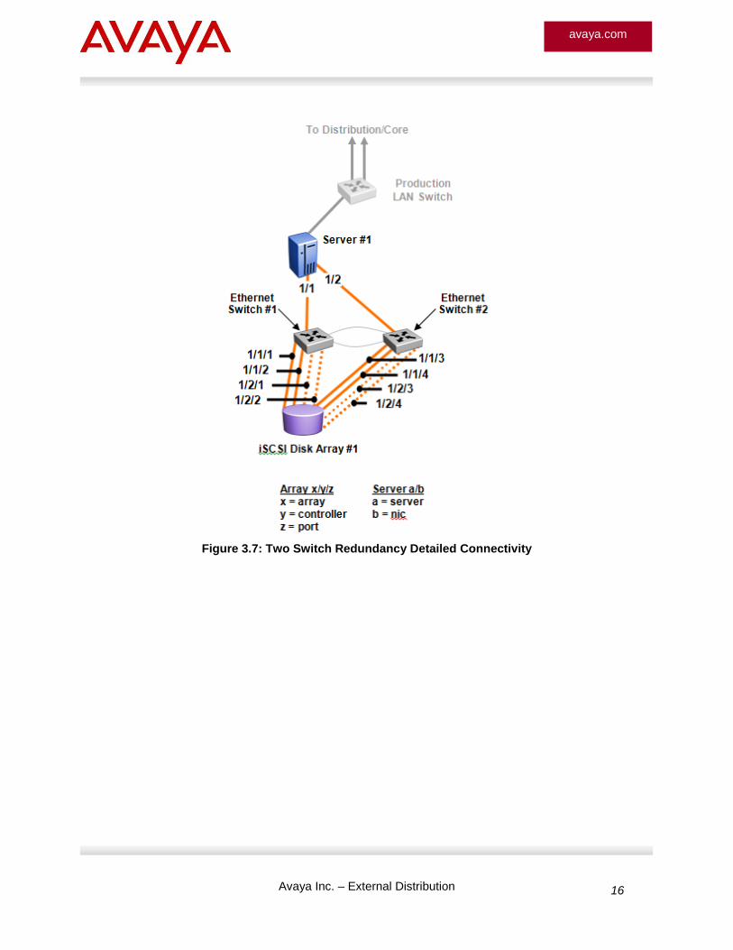
Figure 3.7 shows the details of a single array’s connections into the Ethernet switch stack along with the connections from a Server. The methodology used in the design spreads the connections between the switches in the stack and across the individual switches to maximize the buffer usage on the Ethernet switch. This design also leverages the high performance stacking bandwidth of the ERS 5000 series switches to maximize performance of the iSCSI SAN. With the use of MPIO (multipath I/O) on the iSCSI initiators, the traffic patterns between servers and arrays is somewhat random and therefore necessitates a high bandwidth connection between switches as traffic from server to array or from array to server may very well cross the stack.
Avaya Inc. – External Distribution 16
avaya.com
Figure 3.7: Two Switch Redundancy Detailed Connectivity
Avaya Inc. – External Distribution 17
avaya.com
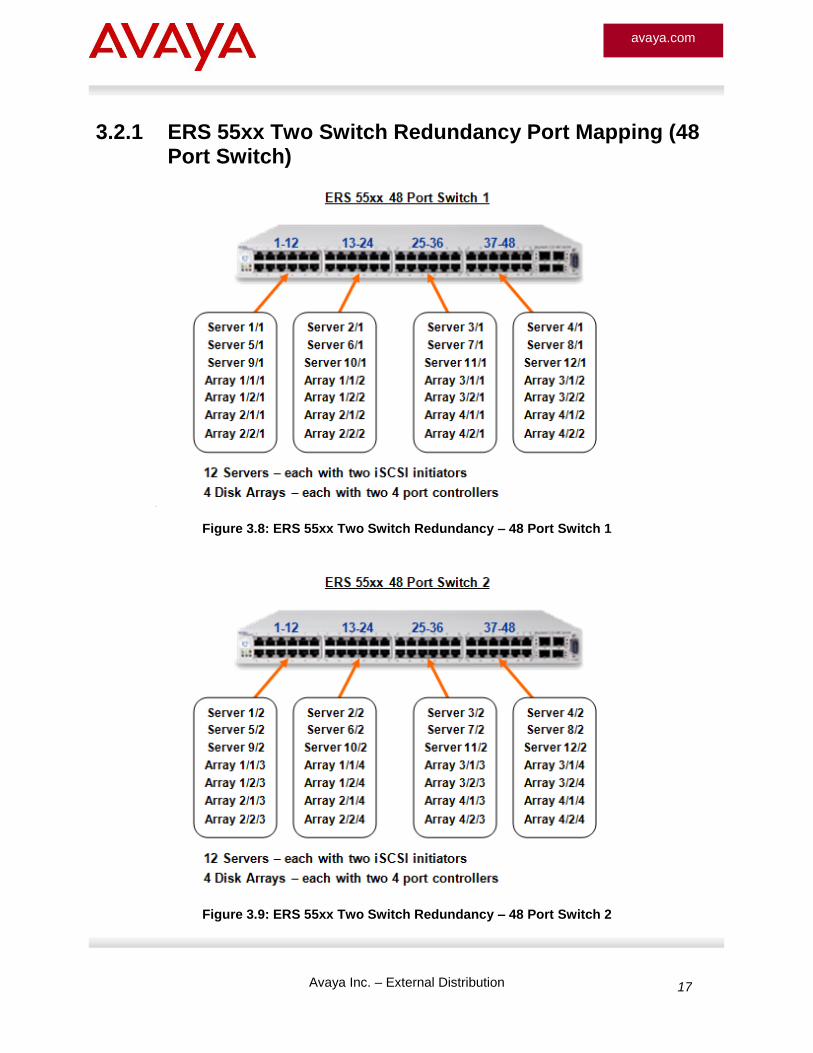
3.2.1 ERS 55xx Two Switch Redundancy Port Mapping (48 Port Switch)
Figure 3.8: ERS 55xx Two Switch Redundancy – 48 Port Switch 1
Figure 3.9: ERS 55xx Two Switch Redundancy – 48 Port Switch 2
Avaya Inc. – External Distribution 18
avaya.com
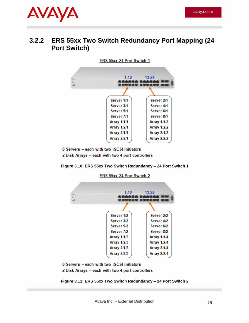
3.2.2 ERS 55xx Two Switch Redundancy Port Mapping (24 Port Switch)
Figure 3.10: ERS 55xx Two Switch Redundancy – 24 Port Switch 1
Figure 3.11: ERS 55xx Two Switch Redundancy – 24 Port Switch 2
Avaya Inc. – External Distribution 19
avaya.com
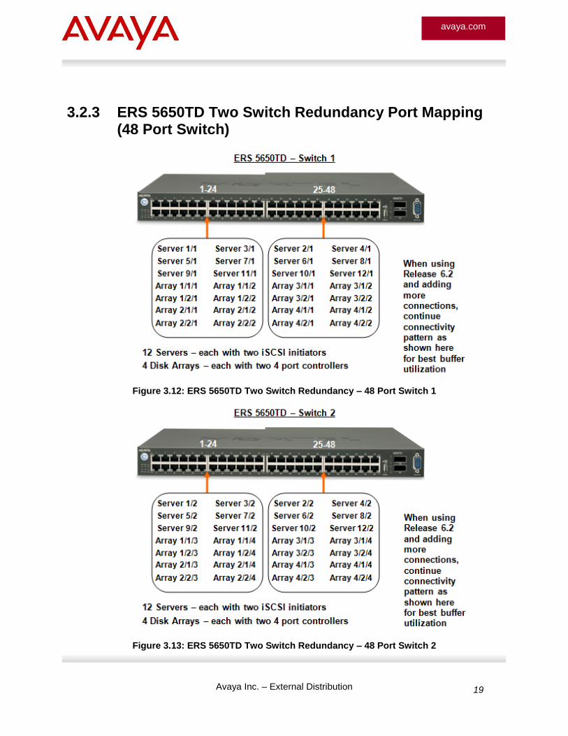
3.2.3 ERS 5650TD Two Switch Redundancy Port Mapping (48 Port Switch)
Figure 3.12: ERS 5650TD Two Switch Redundancy – 48 Port Switch 1
Figure 3.13: ERS 5650TD Two Switch Redundancy – 48 Port Switch 2
Avaya Inc. – External Distribution 20
avaya.com
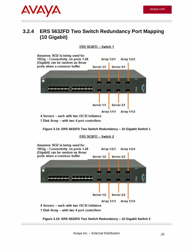
3.2.4 ERS 5632FD Two Switch Redundancy Port Mapping (10 Gigabit)
Figure 3.14: ERS 5632FD Two Switch Redundancy – 10 Gigabit Switch 1
Figure 3.15: ERS 5632FD Two Switch Redundancy – 10 Gigabit Switch 2
Avaya Inc. – External Distribution 21
avaya.com
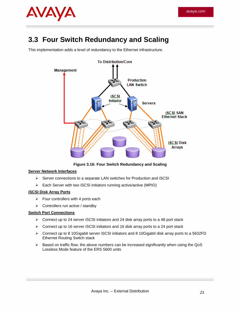
3.3 Four Switch Redundancy and Scaling
This implementation adds a level of redundancy to the Ethernet infrastructure.
Figure 3.16: Four Switch Redundancy and Scaling
Server Network Interfaces
Server connections to a separate LAN switches for Production and iSCSI
Each Server with two iSCSI initiators running active/active (MPIO)
iSCSI Disk Array Ports
Four controllers with 4 ports each
Controllers run active / standby
Switch Port Connections
Connect up to 24 server iSCSI initiators and 24 disk array ports to a 48 port stack
Connect up to 16 server iSCSI initiators and 16 disk array ports to a 24 port stack
Connect up to 8 10Gigabit server iSCSI initiators and 8 10Gigabit disk array ports to a 5632FD Ethernet Routing Switch stack
Based on traffic flow, the above numbers can be increased significantly when using the QoS Lossless Mode feature of the ERS 5600 units
Avaya Inc. – External Distribution 22
avaya.com
iSCSI SAN Ethernet Switch Configuration
Queue Set / Buffer setting of “1/Large”
Queue Set / Buffer setting of “2/Lossless” for ERS 5600 running release 6.2 and complying with design/configuration rules described in Section 3.0
Single VLAN for iSCSI
Disable Spanning Tree on all ports connected to iSCSI initiators and disk array ports
For this implementation, the Server NICs are assumed to be running active/active using MPIO and the arrays are running active/standby controllers. Controller 1 in each array is active and controller 2 in each array is standby. The standby controller will only take over and pass traffic if the active controller totally fails. Losing a single port or multiple ports on a controller will not initiate the standby to takeover.
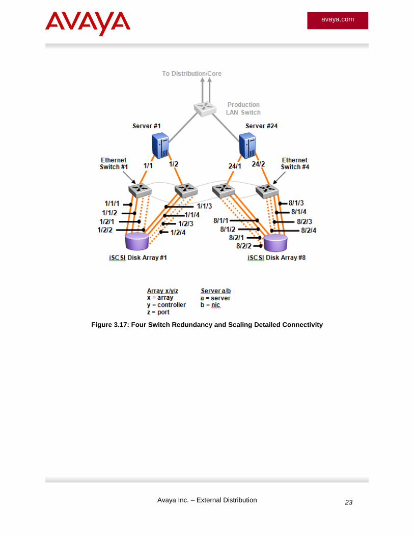
Figure 3.17 shows the details of a single array’s connections into the Ethernet switch stack along with the connections from a Server. The methodology used in the design spreads the connections between the switches in the stack and across the individual switches to maximize the buffer usage on the Ethernet switch. This design also leverages the high performance stacking bandwidth of the ERS 5000 series switches to maximize performance of the iSCSI SAN. With the use of MPIO (multipath I/O) on the iSCSI initiators, the traffic patterns between servers and arrays is somewhat random and therefore necessitates a high bandwidth connection between switches as traffic from server to array or from array to server may very well cross the stack.
When scaling the iSCSI SAN from a two switch topology to a four switch topology, there are different ways to connect the disk arrays. For simplicity, this example basically replicates the two switch implementation to double the capacity of servers and arrays. It is also very beneficial to connect servers and their corresponding arrays to the same switches when possible. For example, the topology below assumes servers 1-12 will use Arrays 1-4. If all servers will use all arrays, then spreading the array connections across all switches in the stack may provide a better traffic flow distribution.
Avaya Inc. – External Distribution 23
avaya.com
Figure 3.17: Four Switch Redundancy and Scaling Detailed Connectivity
Avaya Inc. – External Distribution 24
avaya.com
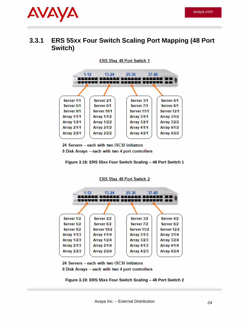
3.3.1 ERS 55xx Four Switch Scaling Port Mapping (48 Port Switch)
Figure 3.18: ERS 55xx Four Switch Scaling – 48 Port Switch 1
Figure 3.19: ERS 55xx Four Switch Scaling – 48 Port Switch 2
Avaya Inc. – External Distribution 25
avaya.com
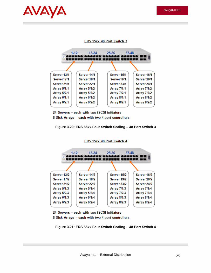
Figure 3.20: ERS 55xx Four Switch Scaling – 48 Port Switch 3
Figure 3.21: ERS 55xx Four Switch Scaling – 48 Port Switch 4

Avaya Inc. – External Distribution 26
avaya.com
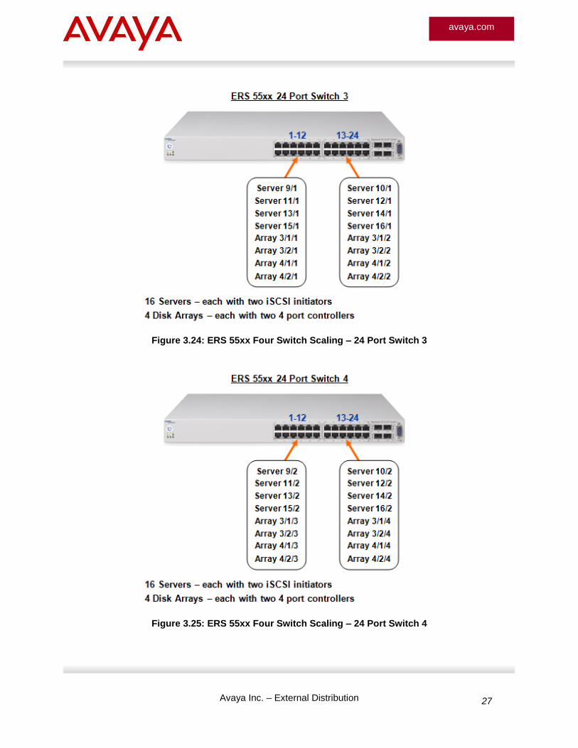
3.3.2 ERS 55xx Four Switch Scaling Port Mapping (24 Port Switch)
Figure 3.22: ERS 55xx Four Switch Scaling – 24 Port Switch 1
Figure 3.23: ERS 55xx Four Switch Scaling – 24 Port Switch 2
Avaya Inc. – External Distribution 27
avaya.com
Figure 3.24: ERS 55xx Four Switch Scaling – 24 Port Switch 3
Figure 3.25: ERS 55xx Four Switch Scaling – 24 Port Switch 4
Avaya Inc. – External Distribution 28
avaya.com
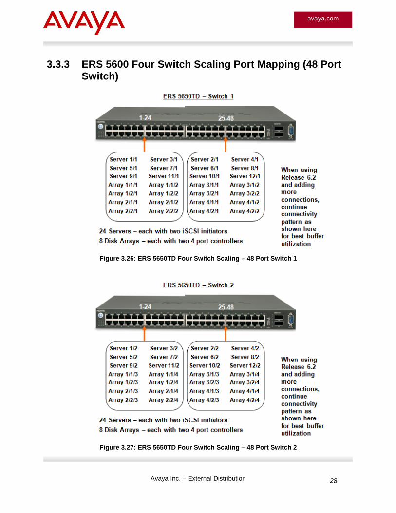
3.3.3 ERS 5600 Four Switch Scaling Port Mapping (48 Port Switch)
Figure 3.26: ERS 5650TD Four Switch Scaling – 48 Port Switch 1
Figure 3.27: ERS 5650TD Four Switch Scaling – 48 Port Switch 2
Avaya Inc. – External Distribution 29
avaya.com
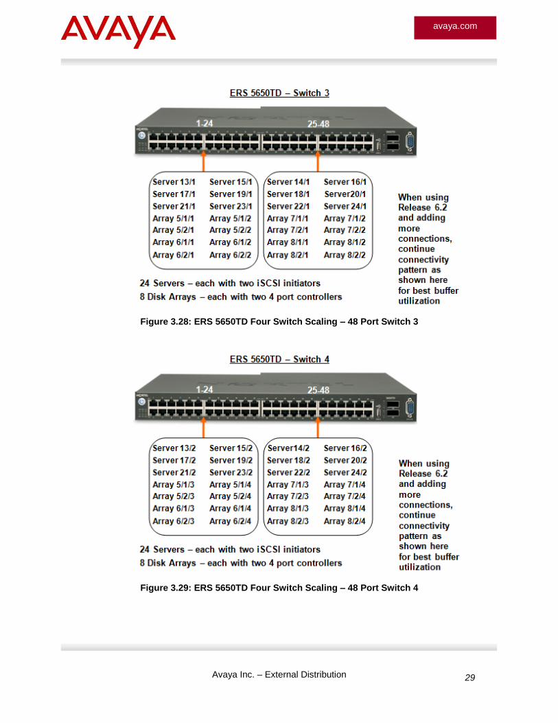
Figure 3.28: ERS 5650TD Four Switch Scaling – 48 Port Switch 3
Figure 3.29: ERS 5650TD Four Switch Scaling – 48 Port Switch 4
Avaya Inc. – External Distribution 30
avaya.com
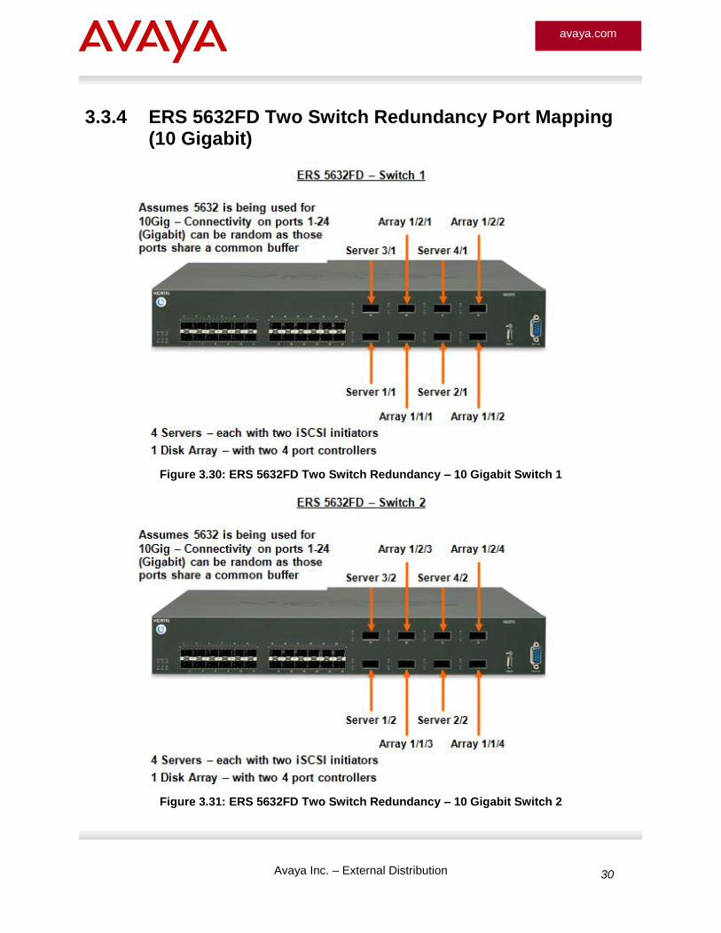
3.3.4 ERS 5632FD Two Switch Redundancy Port Mapping (10 Gigabit)
Figure 3.30: ERS 5632FD Two Switch Redundancy – 10 Gigabit Switch 1
Figure 3.31: ERS 5632FD Two Switch Redundancy – 10 Gigabit Switch 2
Avaya Inc. – External Distribution 31
avaya.com
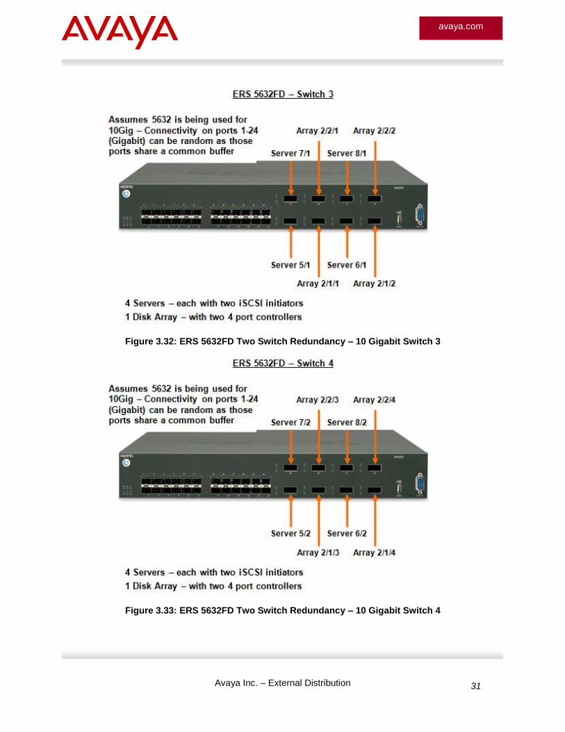
Figure 3.32: ERS 5632FD Two Switch Redundancy – 10 Gigabit Switch 3
Figure 3.33: ERS 5632FD Two Switch Redundancy – 10 Gigabit Switch 4
Avaya Inc. – External Distribution 32
avaya.com
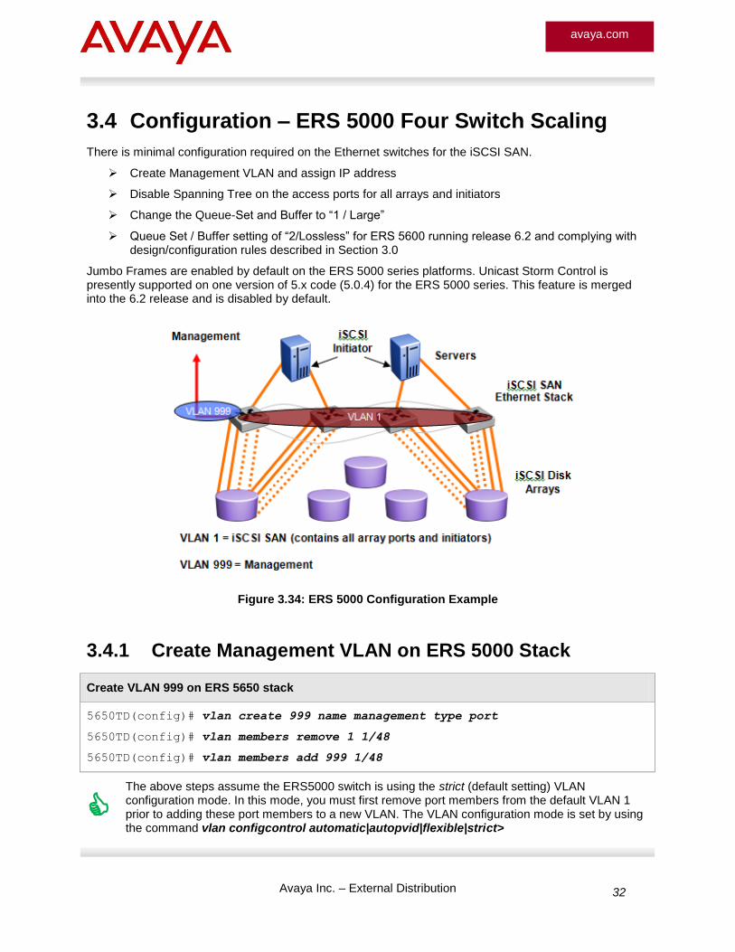
3.4 Configuration – ERS 5000 Four Switch Scaling
There is minimal configuration required on the Ethernet switches for the iSCSI SAN.
Create Management VLAN and assign IP address
Disable Spanning Tree on the access ports for all arrays and initiators
Change the Queue-Set and Buffer to “1 / Large”
Queue Set / Buffer setting of “2/Lossless” for ERS 5600 running release 6.2 and complying with design/configuration rules described in Section 3.0
Jumbo Frames are enabled by default on the ERS 5000 series platforms. Unicast Storm Control is presently supported on one version of 5.x code (5.0.4) for the ERS 5000 series. This feature is merged into the 6.2 release and is disabled by default.
Figure 3.34: ERS 5000 Configuration Example
3.4.1 Create Management VLAN on ERS 5000 Stack
Create VLAN 999 on ERS 5650 stack
5650TD(config)# vlan create 999 name management type port
5650TD(config)# vlan members remove 1 1/48
5650TD(config)# vlan members add 999 1/48
The above steps assume the ERS5000 switch is using the strict (default setting) VLAN configuration mode. In this mode, you must first remove port members from the default VLAN 1 prior to adding these port members to a new VLAN. The VLAN configuration mode is set by using the command vlan configcontrol automatic|autopvid|flexible|strict>
Avaya Inc. – External Distribution 33
avaya.com
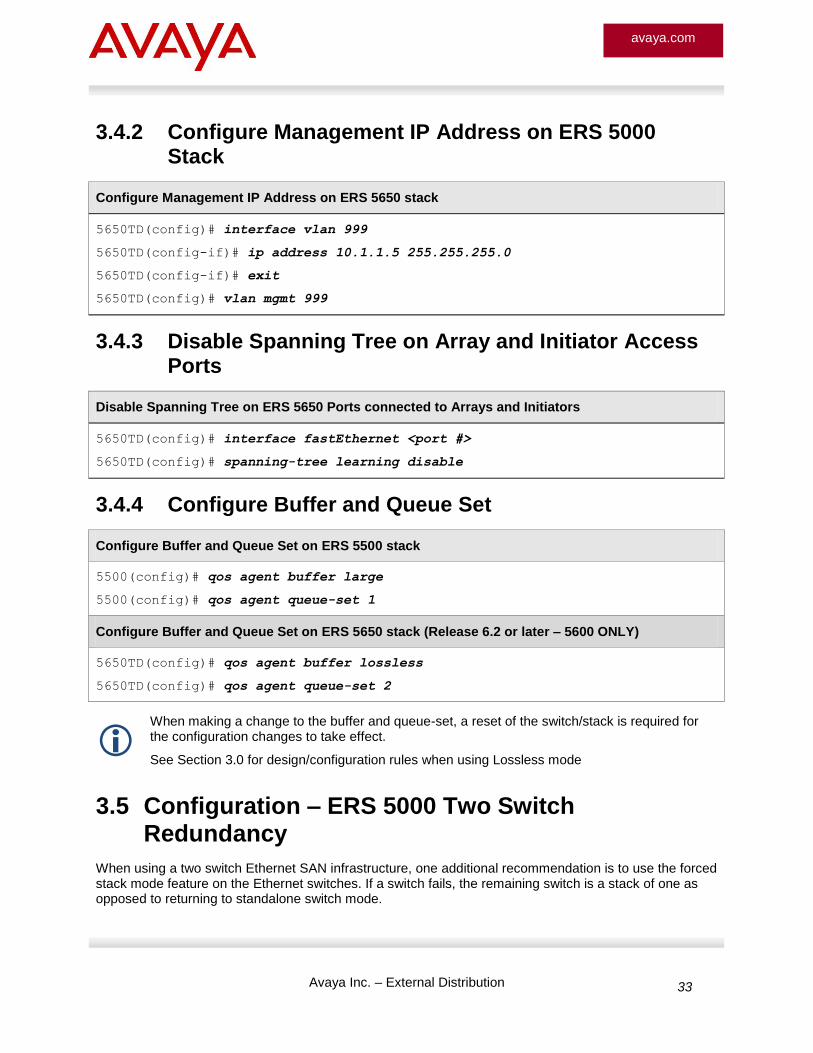
3.4.2 Configure Management IP Address on ERS 5000 Stack
Configure Management IP Address on ERS 5650 stack
5650TD(config)# interface vlan 999
5650TD(config-if)# ip address 10.1.1.5 255.255.255.0
5650TD(config-if)# exit
5650TD(config)# vlan mgmt 999
3.4.3 Disable Spanning Tree on Array and Initiator Access Ports
Disable Spanning Tree on ERS 5650 Ports connected to Arrays and Initiators
5650TD(config)# interface fastEthernet <port #>
5650TD(config)# spanning-tree learning disable
3.4.4 Configure Buffer and Queue Set
Configure Buffer and Queue Set on ERS 5500 stack
5500(config)# qos agent buffer large
5500(config)# qos agent queue-set 1
Configure Buffer and Queue Set on ERS 5650 stack (Release 6.2 or later – 5600 ONLY)
5650TD(config)# qos agent buffer lossless
5650TD(config)# qos agent queue-set 2
When making a change to the buffer and queue-set, a reset of the switch/stack is required for the configuration changes to take effect.
See Section 3.0 for design/configuration rules when using Lossless mode
3.5 Configuration – ERS 5000 Two Switch Redundancy
When using a two switch Ethernet SAN infrastructure, one additional recommendation is to use the forced stack mode feature on the Ethernet switches. If a switch fails, the remaining switch is a stack of one as opposed to returning to standalone switch mode.
Avaya Inc. – External Distribution 34
avaya.com
Configure Forced Stack Mode on ERS 5650 stack
5650TD(config)# stack forced-mode
3.6 Configuration Example – ERS 8600 Single Switch
The ERS 8600 can serve as the Ethernet infrastructure for an iSCSI SAN. As in the case with the stackables, it is recommended to increase queue buffers and spread the iSCSI initiators and iSCSI array ports across the I/O modules to assure maximize performance and minimize packet loss. The recommendation shown is an example distribution of connectivity and does not reflect high end scalability numbers.
3.6.1 ERS 8600 I/O Module Architecture – Understanding Lanes
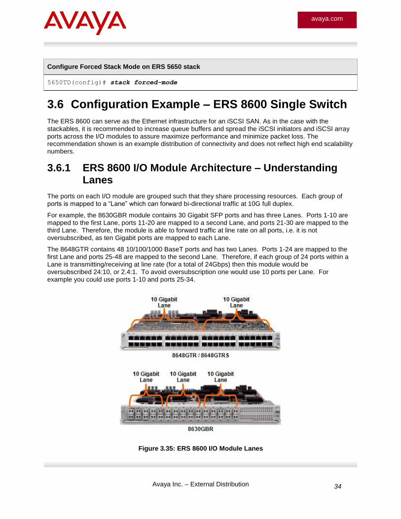
The ports on each I/O module are grouped such that they share processing resources. Each group of ports is mapped to a “Lane” which can forward bi-directional traffic at 10G full duplex.
For example, the 8630GBR module contains 30 Gigabit SFP ports and has three Lanes. Ports 1-10 are mapped to the first Lane, ports 11-20 are mapped to a second Lane, and ports 21-30 are mapped to the third Lane. Therefore, the module is able to forward traffic at line rate on all ports, i.e. it is not oversubscribed, as ten Gigabit ports are mapped to each Lane.
The 8648GTR contains 48 10/100/1000 BaseT ports and has two Lanes. Ports 1-24 are mapped to the first Lane and ports 25-48 are mapped to the second Lane. Therefore, if each group of 24 ports within a Lane is transmitting/receiving at line rate (for a total of 24Gbps) then this module would be oversubscribed 24:10, or 2.4:1. To avoid oversubscription one would use 10 ports per Lane. For example you could use ports 1-10 and ports 25-34.
Figure 3.35: ERS 8600 I/O Module Lanes
Avaya Inc. – External Distribution 35
avaya.com
3.6.2 ERS 8600 I/O Module Architecture – Understanding Queues
By default, there is an Egress Queue Set (type 8) containing 8 queues that is applied to 10/100/1000BaseT ports on the 8648GTR and GTRS module. A second Egress Queue Set (type 64) containing 8 queues is applied to fiber Gigabit and 10 Gigabit Ethernet interfaces. The “type 8” and “type 64” refer to the maximum number of queues that can be configured in the set.
On each R/RS module port an Egress Queue Set is applied that defines the following:
Amount of bandwidth that should be reserved for a given Class of Service (CoS)
Rate at which traffic in a given CoS can burst up to
Type of queue that each CoS uses – ex. strict, weighted queue, low priority queue
Number of buffers allocated to the queue
This guide focuses on the first queue set since iSCSI initiators and arrays are typically connected to copper ports on the ERS 8600. The queue set contains 8 queues and by default only the Critical/Network queue and Standard (Default) queues are used. The Critical/Network queue is used to transmit all network control traffic (i.e. Spanning Tree BPDUs, OSPF Hellos, etc.), while the Standard (Default) queue is the “Best Effort” queue which all transit traffic uses by default.
There are 32,760 pages available per Lane. The number of pages configured for each queue represents the number of pages to which the queue can potentially grow. Pages are not statically allocated, rather are used by the queue as needed. As a result the limits per queue, per port, and per Lane are the same, i.e. 32,760. It is possible to configure queues such that the sum total of all pages is greater than 32760. However this is not recommended as the pool of 32760 could be oversubscribed and results would be unpredictable.
3.6.3 ERS 8600 Basic Configuration Recommendations
There are only a few configuration steps recommended for an iSCSI SAN deployment.
Increase buffers to 1024 for the Best Effort queue
Single VLAN for iSCSI
Disable Spanning Tree on all ports connected to iSCSI initiators and disk array ports or enable STP FastStart if Spanning Tree is desired
Enable flow-control with a timeout of 65535 (default value for ERS 8600)
Distribute iSCSI initiators and iSCSI disk array ports across Lanes in alternating fashion (similar to connectivity shown on the stackables)
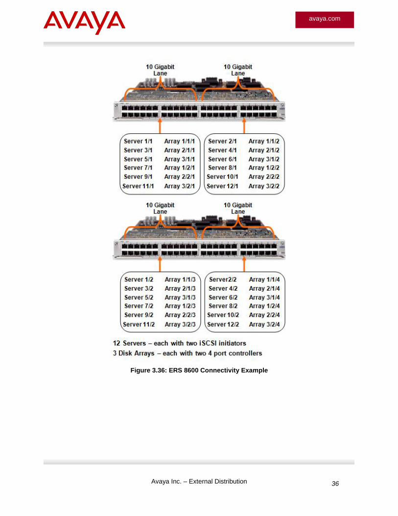
Figure 3.36 shows an example distribution of iSCSI initiators and iSCSI disk array ports spread across two ERS 8648GTR or ERS 8648GTRS modules. This does not represent high end scaling limits of the ERS 8600 in regard to iSCSI, but instead is shown to better understand the optimal connectivity for the iSCSI ports. Distributing the connections across the Lanes will provide optimal performance. A very conservative approach would be to limit the number of Gigabit connections to ten per Lane to insure non-blocking performance. However, this is not a requirement as the buffering and flow control capabilities of the ERS 8600 will allow more connections per Lane without impacting over iSCSI SAN performance.
Avaya Inc. – External Distribution 36
avaya.com
Figure 3.36: ERS 8600 Connectivity Example
Avaya Inc. – External Distribution 37
avaya.com
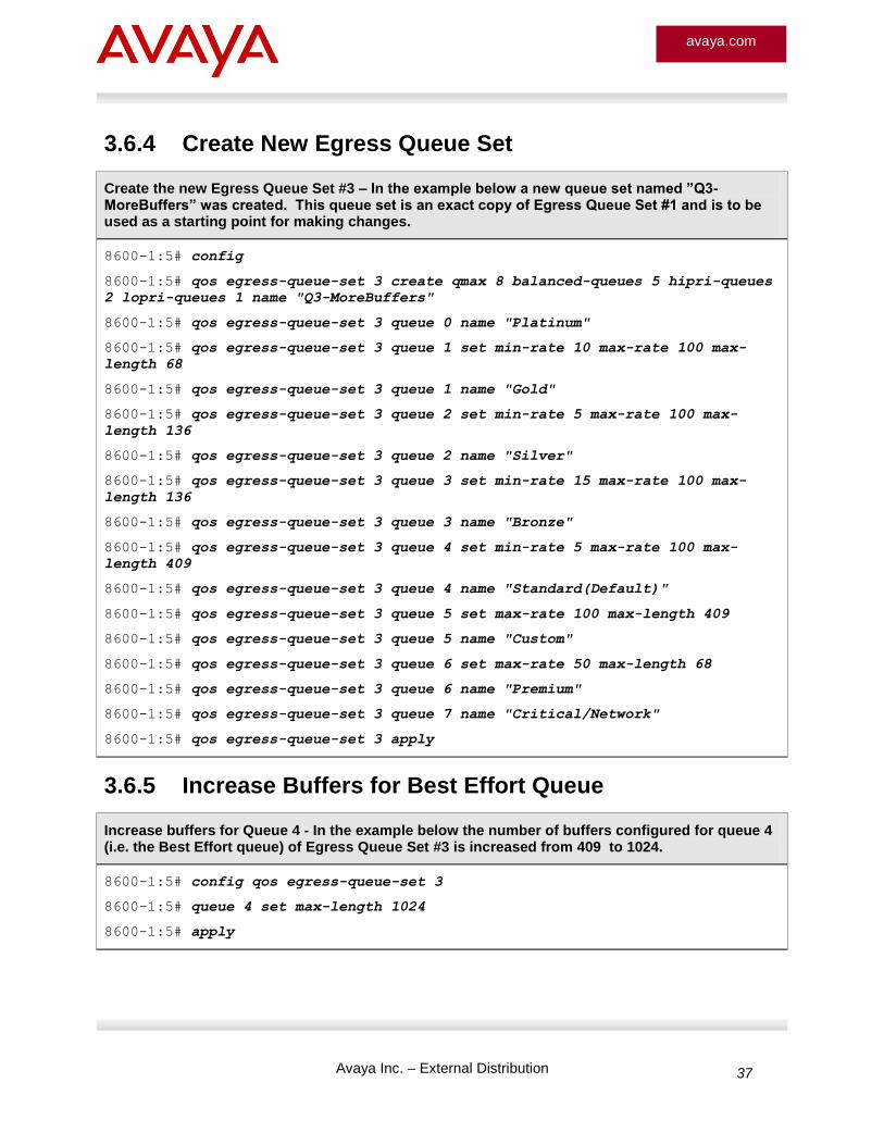
3.6.4 Create New Egress Queue Set
Create the new Egress Queue Set #3 – In the example below a new queue set named ”Q3-MoreBuffers” was created. This queue set is an exact copy of Egress Queue Set #1 and is to be used as a starting point for making changes.
8600-1:5# config
8600-1:5# qos egress-queue-set 3 create qmax 8 balanced-queues 5 hipri-queues
2 lopri-queues 1 name "Q3-MoreBuffers"
8600-1:5# qos egress-queue-set 3 queue 0 name "Platinum"
8600-1:5# qos egress-queue-set 3 queue 1 set min-rate 10 max-rate 100 max-
length 68
8600-1:5# qos egress-queue-set 3 queue 1 name "Gold"
8600-1:5# qos egress-queue-set 3 queue 2 set min-rate 5 max-rate 100 max-
length 136
8600-1:5# qos egress-queue-set 3 queue 2 name "Silver"
8600-1:5# qos egress-queue-set 3 queue 3 set min-rate 15 max-rate 100 max-
length 136
8600-1:5# qos egress-queue-set 3 queue 3 name "Bronze"
8600-1:5# qos egress-queue-set 3 queue 4 set min-rate 5 max-rate 100 max-
length 409
8600-1:5# qos egress-queue-set 3 queue 4 name "Standard(Default)"
8600-1:5# qos egress-queue-set 3 queue 5 set max-rate 100 max-length 409
8600-1:5# qos egress-queue-set 3 queue 5 name "Custom"
8600-1:5# qos egress-queue-set 3 queue 6 set max-rate 50 max-length 68
8600-1:5# qos egress-queue-set 3 queue 6 name "Premium"
8600-1:5# qos egress-queue-set 3 queue 7 name "Critical/Network"
8600-1:5# qos egress-queue-set 3 apply
3.6.5 Increase Buffers for Best Effort Queue
Increase buffers for Queue 4 - In the example below the number of buffers configured for queue 4 (i.e. the Best Effort queue) of Egress Queue Set #3 is increased from 409 to 1024.
8600-1:5# config qos egress-queue-set 3
8600-1:5# queue 4 set max-length 1024
8600-1:5# apply
Avaya Inc. – External Distribution 38
avaya.com
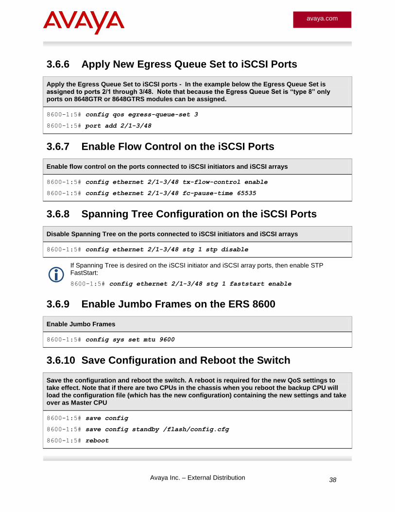
3.6.6 Apply New Egress Queue Set to iSCSI Ports
Apply the Egress Queue Set to iSCSI ports - In the example below the Egress Queue Set is assigned to ports 2/1 through 3/48. Note that because the Egress Queue Set is “type 8” only ports on 8648GTR or 8648GTRS modules can be assigned.
8600-1:5# config qos egress-queue-set 3
8600-1:5# port add 2/1-3/48
3.6.7 Enable Flow Control on the iSCSI Ports
Enable flow control on the ports connected to iSCSI initiators and iSCSI arrays
8600-1:5# config ethernet 2/1-3/48 tx-flow-control enable
8600-1:5# config ethernet 2/1-3/48 fc-pause-time 65535
3.6.8 Spanning Tree Configuration on the iSCSI Ports
Disable Spanning Tree on the ports connected to iSCSI initiators and iSCSI arrays
8600-1:5# config ethernet 2/1-3/48 stg 1 stp disable
If Spanning Tree is desired on the iSCSI initiator and iSCSI array ports, then enable STP FastStart:
8600-1:5# config ethernet 2/1-3/48 stg 1 faststart enable
3.6.9 Enable Jumbo Frames on the ERS 8600
Enable Jumbo Frames
8600-1:5# config sys set mtu 9600
3.6.10 Save Configuration and Reboot the Switch
Save the configuration and reboot the switch. A reboot is required for the new QoS settings to take effect. Note that if there are two CPUs in the chassis when you reboot the backup CPU will load the configuration file (which has the new configuration) containing the new settings and take over as Master CPU
8600-1:5# save config
8600-1:5# save config standby /flash/config.cfg
8600-1:5# reboot
Avaya Inc. – External Distribution 39
avaya.com
4. Reference Documentation
Document Title Publication Number Description
© 2010 Avaya Inc. All Rights Reserved.
Avaya and the Avaya Logo are trademarks of Avaya Inc. and are registered in the United States and other countries. All trademarks identified by ®, TM or SM are registered marks, trademarks, and service marks, respectively, of Avaya Inc. All other trademarks are the property of their respective owners. Avaya may also have trademark rights in other terms used herein. References to Avaya include the Nortel Enterprise business, which was acquired as of December 18, 2009.