Embed Size (px)
Citation preview

THIS MANUAL CONTAINS TECHNICAL INFORMATION FOR THE ETHERNET PORT OF EDI SIGNAL MONITORS with Ethernet Version 1.8 firmware.
DETAILS OF THE ECCOM OPERATION ARE DESCRIBED IN THE EDI ECCOM OPERATIONS MANUAL (888-1000-001).
EDI PRODUCTS ARE DESIGNED AND MANUFACTURED IN THE USA BY EBERLE DESIGN INC., PHOENIX, ARIZONA, AN ISO 9001:2008 REGISTERED COMPANY.
INFORMATION CONTAINED HEREIN IS PROPRIETARY TECHNICAL INFORMATION OF EBERLE DESIGN INC. PUBLICATION, REPRODUCTION OR USE IN WHOLE OR PART IS NOT PERMITTED EXCEPT UNDER TERMS AGREED UPON IN WRITING.
©COPYRIGHT 2016 EDI.
REVISION: MARCH 2016 pn 888-1000-101
Ethernet Port Quick Start Manual
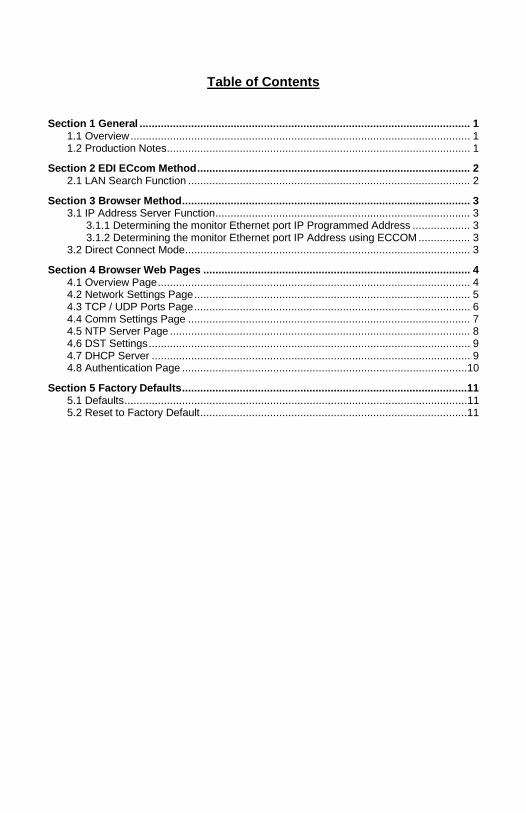
Table of Contents
Section 1 General ............................................................................................................. 1 1.1 Overview ................................................................................................................ 1 1.2 Production Notes .................................................................................................... 1
Section 2 EDI ECcom Method .......................................................................................... 2 2.1 LAN Search Function ............................................................................................. 2
Section 3 Browser Method ............................................................................................... 3 3.1 IP Address Server Function .................................................................................... 3
3.1.1 Determining the monitor Ethernet port IP Programmed Address ................... 3 3.1.2 Determining the monitor Ethernet port IP Address using ECCOM ................. 3
3.2 Direct Connect Mode .............................................................................................. 3 Section 4 Browser Web Pages ........................................................................................ 4
4.1 Overview Page ....................................................................................................... 4 4.2 Network Settings Page ........................................................................................... 5 4.3 TCP / UDP Ports Page ........................................................................................... 6 4.4 Comm Settings Page ............................................................................................. 7 4.5 NTP Server Page ................................................................................................... 8 4.6 DST Settings .......................................................................................................... 9 4.7 DHCP Server ......................................................................................................... 9 4.8 Authentication Page ..............................................................................................10
Section 5 Factory Defaults ..............................................................................................11 5.1 Defaults .................................................................................................................11 5.2 Reset to Factory Default ........................................................................................11

Ethernet Port Quick-Start Guide
Eberle Design Inc. Page 1
Section 1 General
1.1 OVERVIEW
The Ethernet port of EDI signal monitors is used to transfer status and event log information between a networked Personal Computer (PC) and the monitor unit. The PC is intended to operate with EDI ECcom Signal Monitor Communications software.
The EDI ECcom software is distributed free of charge and can be obtained from the EDI web site at www.EDItraffic.com. The current production release of ECcom is 4.2.
The networking parameters of the Ethernet port can be configured using two different methods; the EDI ECcom program (Section 2) or a standard internet browser (Section 3). Which method is used depends on the user preference. Some options may be affected by administrator issues on the PC.
Once the network parameters of the Ethernet port are set, the EDI ECcom program is then used to view monitor operational status and event logs. Note that a browser program will not provide access to the monitor status and logs.
1.2 PRODUCTION NOTES
The Ethernet network parameters are typically programmed via the Ethernet interface but can also be loaded from the Datakey of the CMUip-2212, CMUip-212 or 2018KCLip. In these cases the EDI MonitorKey software (version 2.4 or greater) provides the tool to program the network parameters into the Datakey. This requires an installed firmware level as follows:
CMUip-2212 v0115 or greater
CMUip-212 v0122 or greater
2018KCLip v0156 or greater
Ethernet Port Quick-Start Guide
Eberle Design Inc. Page 2
Section 2 EDI ECcom Method
2.1 LAN SEARCH FUNCTION
Operation of the ECcom software package is described in EDI ECcom Software Operations Manual and will not be covered in this manual. The EDI ECcom software is available at no charge from the EDI web site at www.EDItraffic.com.
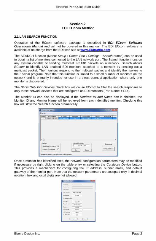
The SEARCH function (Menu: Setup / Comm Port / Settings - Search button) can be used to obtain a list of monitors connected to the LAN network port. The Search function runs on any system capable of sending multicast IP/UDP packets on a network. Search allows ECcom to identify LAN enabled EDI monitors attached to a network by sending out a multicast packet. The monitors respond to the multicast packet and identify themselves to the ECcom program. Note that this function is limited to a small number of monitors on the network and is primarily intended for use in a direct connect application where only one monitor is discovered.
The Show Only EDI Devices check box will cause ECcom to filter the search responses to only those network devices that are configured as EDI monitors (Port Name = EDI).
The Monitor ID can also be displayed. If the Retrieve ID and Name box is checked, the Monitor ID and Monitor Name will be retrieved from each identified monitor. Checking this box will slow the Search function dramatically.
Once a monitor has identified itself, the network configuration parameters may be modified if necessary by right clicking on the table entry or selecting the Configure Device button. This provides a mechanism for configuring the IP address, subnet mask, and default gateway of the monitor port. Note that the network parameters are accepted only in decimal notation; hex and octal digits are not allowed.
Ethernet Port Quick-Start Guide
Eberle Design Inc. Page 3
Section 3 Browser Method
The network parameters of the Ethernet port can be viewed and configured using a standard internet browser program.
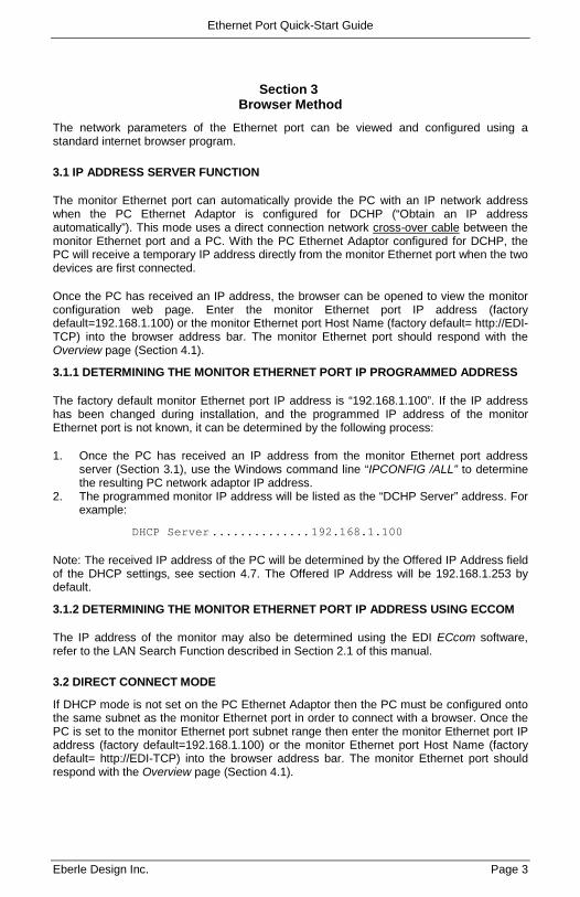
3.1 IP ADDRESS SERVER FUNCTION
The monitor Ethernet port can automatically provide the PC with an IP network address when the PC Ethernet Adaptor is configured for DCHP (“Obtain an IP address automatically”). This mode uses a direct connection network cross-over cable between the monitor Ethernet port and a PC. With the PC Ethernet Adaptor configured for DCHP, the PC will receive a temporary IP address directly from the monitor Ethernet port when the two devices are first connected.
Once the PC has received an IP address, the browser can be opened to view the monitor configuration web page. Enter the monitor Ethernet port IP address (factory default=192.168.1.100) or the monitor Ethernet port Host Name (factory default= http://EDI-TCP) into the browser address bar. The monitor Ethernet port should respond with the Overview page (Section 4.1).
3.1.1 DETERMINING THE MONITOR ETHERNET PORT IP PROGRAMMED ADDRESS
The factory default monitor Ethernet port IP address is “192.168.1.100”. If the IP address has been changed during installation, and the programmed IP address of the monitor Ethernet port is not known, it can be determined by the following process:
1. Once the PC has received an IP address from the monitor Ethernet port address server (Section 3.1), use the Windows command line “IPCONFIG /ALL” to determine the resulting PC network adaptor IP address.
2. The programmed monitor IP address will be listed as the “DCHP Server” address. For example:
DHCP Server .............. 192.168.1.100
Note: The received IP address of the PC will be determined by the Offered IP Address field of the DHCP settings, see section 4.7. The Offered IP Address will be 192.168.1.253 by default.
3.1.2 DETERMINING THE MONITOR ETHERNET PORT IP ADDRESS USING ECCOM
The IP address of the monitor may also be determined using the EDI ECcom software, refer to the LAN Search Function described in Section 2.1 of this manual.
3.2 DIRECT CONNECT MODE
If DHCP mode is not set on the PC Ethernet Adaptor then the PC must be configured onto the same subnet as the monitor Ethernet port in order to connect with a browser. Once the PC is set to the monitor Ethernet port subnet range then enter the monitor Ethernet port IP address (factory default=192.168.1.100) or the monitor Ethernet port Host Name (factory default= http://EDI-TCP) into the browser address bar. The monitor Ethernet port should respond with the Overview page (Section 4.1).
Ethernet Port Quick-Start Guide
Eberle Design Inc. Page 4
Section 4 Browser Web Pages
Once a connection is made with the PC browser, the following web pages will be provided by the monitor Ethernet port. These pages can then be used to configure the monitor Ethernet port to the field application requirements.
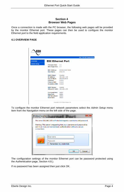
4.1 OVERVIEW PAGE
To configure the monitor Ethernet port network parameters select the Admin Setup menu item from the Navigation menu on the left side of the page.
The configuration settings of the monitor Ethernet port can be password protected using the Authentication page, Section 4.8.).
If no password has been assigned then just click OK.
Ethernet Port Quick-Start Guide
Eberle Design Inc. Page 5
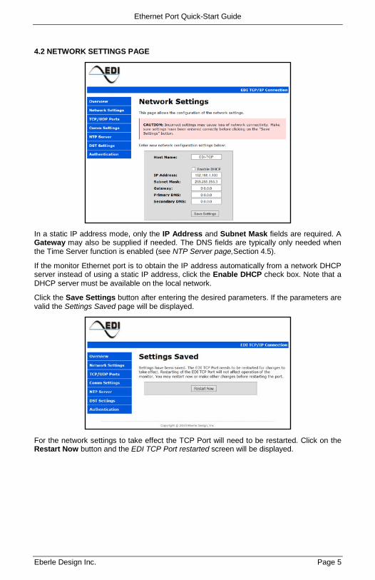
4.2 NETWORK SETTINGS PAGE
In a static IP address mode, only the IP Address and Subnet Mask fields are required. A Gateway may also be supplied if needed. The DNS fields are typically only needed when the Time Server function is enabled (see NTP Server page,Section 4.5).
If the monitor Ethernet port is to obtain the IP address automatically from a network DHCP server instead of using a static IP address, click the Enable DHCP check box. Note that a DHCP server must be available on the local network.
Click the Save Settings button after entering the desired parameters. If the parameters are valid the Settings Saved page will be displayed.
For the network settings to take effect the TCP Port will need to be restarted. Click on the Restart Now button and the EDI TCP Port restarted screen will be displayed.
Ethernet Port Quick-Start Guide
Eberle Design Inc. Page 6
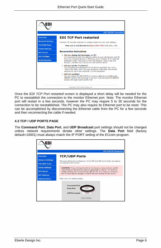
Once the EDI TCP Port restarted screen is displayed a short delay will be needed for the PC to reestablish the connection to the monitor Ethernet port. Note: The monitor Ethernet port will restart in a few seconds, however the PC may require 5 to 30 seconds for the connection to be reestablished. The PC may also require its Ethernet port to be reset. This can be accomplished by disconnecting the Ethernet cable from the PC for a few seconds and then reconnecting the cable if needed.
4.3 TCP / UDP PORTS PAGE
The Command Port, Data Port, and UDP Broadcast port settings should not be changed unless network requirements dictate other settings. The Data Port field (factory default=10001) must always match the IP PORT setting of the ECcom program.
Ethernet Port Quick-Start Guide
Eberle Design Inc. Page 7
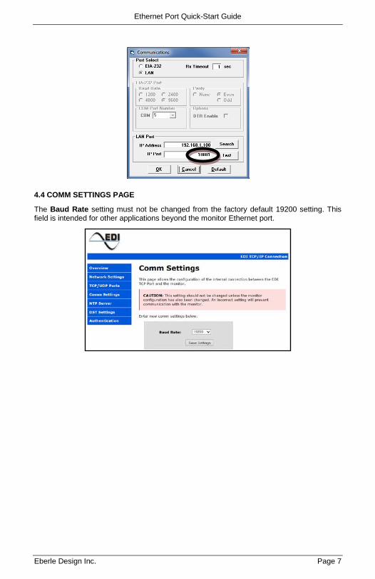
4.4 COMM SETTINGS PAGE
The Baud Rate setting must not be changed from the factory default 19200 setting. This field is intended for other applications beyond the monitor Ethernet port.
Ethernet Port Quick-Start Guide
Eberle Design Inc. Page 8
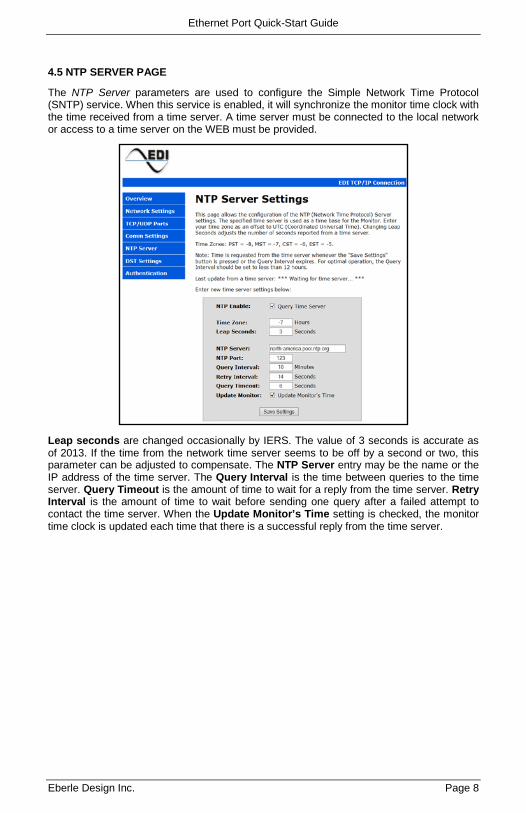
4.5 NTP SERVER PAGE
The NTP Server parameters are used to configure the Simple Network Time Protocol (SNTP) service. When this service is enabled, it will synchronize the monitor time clock with the time received from a time server. A time server must be connected to the local network or access to a time server on the WEB must be provided.
Leap seconds are changed occasionally by IERS. The value of 3 seconds is accurate as of 2013. If the time from the network time server seems to be off by a second or two, this parameter can be adjusted to compensate. The NTP Server entry may be the name or the IP address of the time server. The Query Interval is the time between queries to the time server. Query Timeout is the amount of time to wait for a reply from the time server. Retry Interval is the amount of time to wait before sending one query after a failed attempt to contact the time server. When the Update Monitor’s Time setting is checked, the monitor time clock is updated each time that there is a successful reply from the time server.
Ethernet Port Quick-Start Guide
Eberle Design Inc. Page 9
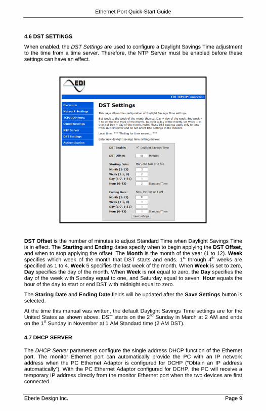
4.6 DST SETTINGS
When enabled, the DST Settings are used to configure a Daylight Savings Time adjustment to the time from a time server. Therefore, the NTP Server must be enabled before these settings can have an effect.
DST Offset is the number of minutes to adjust Standard Time when Daylight Savings Time is in effect. The Starting and Ending dates specify when to begin applying the DST Offset, and when to stop applying the offset. The Month is the month of the year (1 to 12). Week specifies which week of the month that DST starts and ends. 1st through 4th weeks are specified as 1 to 4. Week 5 specifies the last week of the month. When Week is set to zero, Day specifies the day of the month. When Week is not equal to zero, the Day specifies the day of the week with Sunday equal to one, and Saturday equal to seven. Hour equals the hour of the day to start or end DST with midnight equal to zero.
The Staring Date and Ending Date fields will be updated after the Save Settings button is selected.
At the time this manual was written, the default Daylight Savings Time settings are for the United States as shown above. DST starts on the 2nd Sunday in March at 2 AM and ends on the 1st Sunday in November at 1 AM Standard time (2 AM DST).
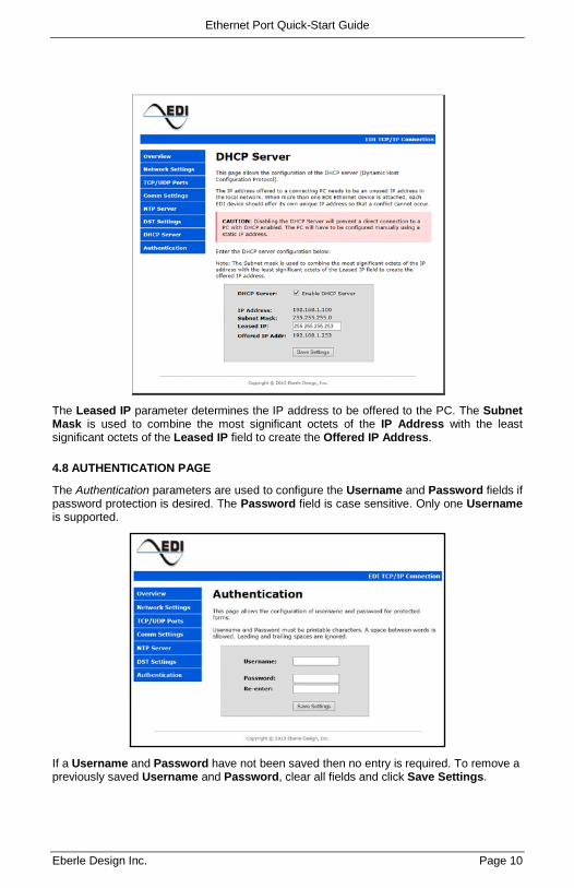
4.7 DHCP SERVER
The DHCP Server parameters configure the single address DHCP function of the Ethernet port. The monitor Ethernet port can automatically provide the PC with an IP network address when the PC Ethernet Adaptor is configured for DCHP (“Obtain an IP address automatically”). With the PC Ethernet Adaptor configured for DCHP, the PC will receive a temporary IP address directly from the monitor Ethernet port when the two devices are first connected.
Ethernet Port Quick-Start Guide
Eberle Design Inc. Page 10
The Leased IP parameter determines the IP address to be offered to the PC. The Subnet Mask is used to combine the most significant octets of the IP Address with the least significant octets of the Leased IP field to create the Offered IP Address.
4.8 AUTHENTICATION PAGE
The Authentication parameters are used to configure the Username and Password fields if password protection is desired. The Password field is case sensitive. Only one Username is supported.
If a Username and Password have not been saved then no entry is required. To remove a previously saved Username and Password, clear all fields and click Save Settings.
Ethernet Port Quick-Start Guide
Eberle Design Inc. Page 11
Section 5 Factory Defaults
5.1 DEFAULTS
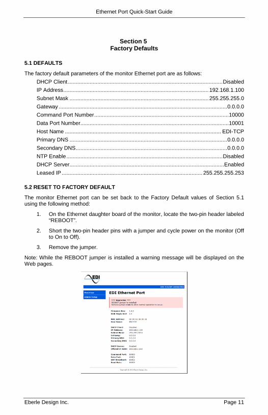
The factory default parameters of the monitor Ethernet port are as follows: DHCP Client .................................................................................................... Disabled IP Address .............................................................................................. 192.168.1.100 Subnet Mask .......................................................................................... 255.255.255.0 Gateway ............................................................................................................. 0.0.0.0 Command Port Number ....................................................................................... 10000 Data Port Number ................................................................................................ 10001 Host Name ..................................................................................................... EDI-TCP Primary DNS ...................................................................................................... 0.0.0.0 Secondary DNS .................................................................................................. 0.0.0.0 NTP Enable ..................................................................................................... Disabled DHCP Server ....................................................................................................Enabled Leased IP ........................................................................................... 255.255.255.253
5.2 RESET TO FACTORY DEFAULT
The monitor Ethernet port can be set back to the Factory Default values of Section 5.1 using the following method:
1. On the Ethernet daughter board of the monitor, locate the two-pin header labeled “REBOOT”.
2. Short the two-pin header pins with a jumper and cycle power on the monitor (Off to On to Off).
3. Remove the jumper.
Note: While the REBOOT jumper is installed a warning message will be displayed on the Web pages.


![Multi-Port Fast Ethernet Print Server1].pdf · Multi-Port Fast Ethernet Print Server FPS-3300 User’s Manual 1](https://img.pdfslide.us/doc/110x75/5f8848bdc824844a0b17dfd3/multi-port-fast-ethernet-print-1pdf-multi-port-fast-ethernet-print-server-fps-3300.jpg)