Embed Size (px)
Citation preview
EA
V643
27.0
1
www.schneider-electric.com
Altivar ProcessEthernet Manual (Embedded)
08/2014
The information provided in this documentation contains general descriptions and/or technical character-istics of the performance of the products contained herein. This documentation is not intended as a substitute for and is not to be used for determining suitability or reliability of these products for specific user applications. It is the duty of any such user or integrator to perform the appropriate and complete risk analysis, evaluation and testing of the products with respect to the relevant specific application or use thereof. Neither Schneider Electric nor any of its affiliates or subsidiaries shall be responsible or liable for misuse of the information contained herein. If you have any suggestions for improvements or amendments or have found errors in this publication, please notify us.
No part of this document may be reproduced in any form or by any means, electronic or mechanical, including photocopying, without express written permission of Schneider Electric.
All pertinent state, regional, and local safety regulations must be observed when installing and using this product. For reasons of safety and to help ensure compliance with documented system data, only the manufacturer should perform repairs to components.
When devices are used for applications with technical safety requirements, the relevant instructions must be followed.
Failure to use Schneider Electric software or approved software with our hardware products may result in injury, harm, or improper operating results.
Failure to observe this information can result in injury or equipment damage.
© 2014 Schneider Electric. All rights reserved.
2 EAV64327 08/2014
Table of Contents
Safety Information . . . . . . . . . . . . . . . . . . . . . . . . . . . . . . . . . . . . . . . . . . . 5About the Book. . . . . . . . . . . . . . . . . . . . . . . . . . . . . . . . . . . . . . . . . . . . . . 9
Chapter 1 Presentation . . . . . . . . . . . . . . . . . . . . . . . . . . . . . . . . . . . . . . . . . . . . . . . . 11Hardware Overview . . . . . . . . . . . . . . . . . . . . . . . . . . . . . . . . . . . . . . . . . . . . . . . . . . . . . . . . 12Software Overview . . . . . . . . . . . . . . . . . . . . . . . . . . . . . . . . . . . . . . . . . . . . . . . . . . . . . . . . 13
Chapter 2 Basics . . . . . . . . . . . . . . . . . . . . . . . . . . . . . . . . . . . . . . . . . . . . . . . . . . . . . 152.1 Introduction . . . . . . . . . . . . . . . . . . . . . . . . . . . . . . . . . . . . . . . . . . . . . . . . . . . . . . . . . . . . . . 16
Overview . . . . . . . . . . . . . . . . . . . . . . . . . . . . . . . . . . . . . . . . . . . . . . . . . . . . . . . . . . . . . . . . 17Network Layer Supported Functions/Protocols . . . . . . . . . . . . . . . . . . . . . . . . . . . . . . . . . . . 18TCP and UDP Protocol . . . . . . . . . . . . . . . . . . . . . . . . . . . . . . . . . . . . . . . . . . . . . . . . . . . . . 20
2.2 Modbus TCP Features . . . . . . . . . . . . . . . . . . . . . . . . . . . . . . . . . . . . . . . . . . . . . . . . . . . . . 22Modbus TCP Frames . . . . . . . . . . . . . . . . . . . . . . . . . . . . . . . . . . . . . . . . . . . . . . . . . . . . . . 23Modbus TCP Servers . . . . . . . . . . . . . . . . . . . . . . . . . . . . . . . . . . . . . . . . . . . . . . . . . . . . . . 24Supported Modbus TCP Functions . . . . . . . . . . . . . . . . . . . . . . . . . . . . . . . . . . . . . . . . . . . . 25Application Profile with Modbus TCP . . . . . . . . . . . . . . . . . . . . . . . . . . . . . . . . . . . . . . . . . . 26
Chapter 3 Hardware Setup . . . . . . . . . . . . . . . . . . . . . . . . . . . . . . . . . . . . . . . . . . . . . 27Hardware Presentation . . . . . . . . . . . . . . . . . . . . . . . . . . . . . . . . . . . . . . . . . . . . . . . . . . . . . 28Firmware Version . . . . . . . . . . . . . . . . . . . . . . . . . . . . . . . . . . . . . . . . . . . . . . . . . . . . . . . . . 29Connection to the Adapter. . . . . . . . . . . . . . . . . . . . . . . . . . . . . . . . . . . . . . . . . . . . . . . . . . . 30Electrical Installation . . . . . . . . . . . . . . . . . . . . . . . . . . . . . . . . . . . . . . . . . . . . . . . . . . . . . . . 31Cable Routing Practice . . . . . . . . . . . . . . . . . . . . . . . . . . . . . . . . . . . . . . . . . . . . . . . . . . . . . 32
Chapter 4 Software Setup . . . . . . . . . . . . . . . . . . . . . . . . . . . . . . . . . . . . . . . . . . . . . . 334.1 Basic Settings . . . . . . . . . . . . . . . . . . . . . . . . . . . . . . . . . . . . . . . . . . . . . . . . . . . . . . . . . . . . 34
IP Parameter Settings . . . . . . . . . . . . . . . . . . . . . . . . . . . . . . . . . . . . . . . . . . . . . . . . . . . . . . 35[Device Name] ( )PAn . . . . . . . . . . . . . . . . . . . . . . . . . . . . . . . . . . . . . . . . . . . . . . . . . . . . 36[IP mode Eth Embd] ( )IM00 . . . . . . . . . . . . . . . . . . . . . . . . . . . . . . . . . . . . . . . . . . . . . . 37[IP Eth Embd] (IC01) (IC02) (IC03) (IC04) . . . . . . . . . . . . . . . . . . . . . . . . . . . 38[IP Mask Eth Embd] (IM01) (IM02) (IM03) (IM04) . . . . . . . . . . . . . . . . . . . . . . 39[IP Gate Eth Embd] (IG01) (IG02) (IG03) (IG04) . . . . . . . . . . . . . . . . . . . . . . . 40[MAC @] (MAC). . . . . . . . . . . . . . . . . . . . . . . . . . . . . . . . . . . . . . . . . . . . . . . . . . . . . . . . . . 41[ETH emb Rx frames] ( )ErXE . . . . . . . . . . . . . . . . . . . . . . . . . . . . . . . . . . . . . . . . . . . . . 42[ETH emb Tx frames] ( )EtXE . . . . . . . . . . . . . . . . . . . . . . . . . . . . . . . . . . . . . . . . . . . . . 43[ETH emb error frames] ( )EErE . . . . . . . . . . . . . . . . . . . . . . . . . . . . . . . . . . . . . . . . . . . 44[Ethernet Rate Data] ( )ArdE . . . . . . . . . . . . . . . . . . . . . . . . . . . . . . . . . . . . . . . . . . . . . . 45[Ethernet Embd cmd.] ( )CMd5 . . . . . . . . . . . . . . . . . . . . . . . . . . . . . . . . . . . . . . . . . . . . 46[Ethernet Embd Ref Freq] ( )LFr5 . . . . . . . . . . . . . . . . . . . . . . . . . . . . . . . . . . . . . . . . . 47[Enable Web Services] ( )EWEE . . . . . . . . . . . . . . . . . . . . . . . . . . . . . . . . . . . . . . . . . . . . 48[Reset EmbWeb Passwd] ( )rWPE . . . . . . . . . . . . . . . . . . . . . . . . . . . . . . . . . . . . . . . . . 49[Ethernet Timeout] ( )ttOb . . . . . . . . . . . . . . . . . . . . . . . . . . . . . . . . . . . . . . . . . . . . . . . 50
4.2 Additional Settings. . . . . . . . . . . . . . . . . . . . . . . . . . . . . . . . . . . . . . . . . . . . . . . . . . . . . . . . . 51FDR Settings . . . . . . . . . . . . . . . . . . . . . . . . . . . . . . . . . . . . . . . . . . . . . . . . . . . . . . . . . . . . . 52[Embedded Eth Com Interrupt] ( )EtHF . . . . . . . . . . . . . . . . . . . . . . . . . . . . . . . . . . . . . 53[External Error] ( )EPF1 . . . . . . . . . . . . . . . . . . . . . . . . . . . . . . . . . . . . . . . . . . . . . . . . . . 54Configuring I/O Scanning . . . . . . . . . . . . . . . . . . . . . . . . . . . . . . . . . . . . . . . . . . . . . . . . . . . 55
4.3 Fast Device Replacement . . . . . . . . . . . . . . . . . . . . . . . . . . . . . . . . . . . . . . . . . . . . . . . . . . . 56Presentation . . . . . . . . . . . . . . . . . . . . . . . . . . . . . . . . . . . . . . . . . . . . . . . . . . . . . . . . . . . . . 57Startup Detailed Behavior . . . . . . . . . . . . . . . . . . . . . . . . . . . . . . . . . . . . . . . . . . . . . . . . . . . 58FDR Operation Behavior . . . . . . . . . . . . . . . . . . . . . . . . . . . . . . . . . . . . . . . . . . . . . . . . . . . . 59Local Configuration . . . . . . . . . . . . . . . . . . . . . . . . . . . . . . . . . . . . . . . . . . . . . . . . . . . . . . . . 60Downloaded Configuration . . . . . . . . . . . . . . . . . . . . . . . . . . . . . . . . . . . . . . . . . . . . . . . . . . 61
EAV64327 08/2014 3
4.4 Communication Profile . . . . . . . . . . . . . . . . . . . . . . . . . . . . . . . . . . . . . . . . . . . . . . . . . . . . . . 63Definition of a Profile . . . . . . . . . . . . . . . . . . . . . . . . . . . . . . . . . . . . . . . . . . . . . . . . . . . . . . . 64Functional Profiles Supported by the Drive . . . . . . . . . . . . . . . . . . . . . . . . . . . . . . . . . . . . . . 65Functional Description . . . . . . . . . . . . . . . . . . . . . . . . . . . . . . . . . . . . . . . . . . . . . . . . . . . . . . 66CIA402 Operating State Diagram . . . . . . . . . . . . . . . . . . . . . . . . . . . . . . . . . . . . . . . . . . . . . 67Description of Operating States . . . . . . . . . . . . . . . . . . . . . . . . . . . . . . . . . . . . . . . . . . . . . . . 68Summary . . . . . . . . . . . . . . . . . . . . . . . . . . . . . . . . . . . . . . . . . . . . . . . . . . . . . . . . . . . . . . . . 70Control Word ( )CMd . . . . . . . . . . . . . . . . . . . . . . . . . . . . . . . . . . . . . . . . . . . . . . . . . . . . . . 71Stop Commands . . . . . . . . . . . . . . . . . . . . . . . . . . . . . . . . . . . . . . . . . . . . . . . . . . . . . . . . . . 72Assigning Control Word Bits . . . . . . . . . . . . . . . . . . . . . . . . . . . . . . . . . . . . . . . . . . . . . . . . . 73Status Word ( )EtA . . . . . . . . . . . . . . . . . . . . . . . . . . . . . . . . . . . . . . . . . . . . . . . . . . . . . . . 74Starting Sequence . . . . . . . . . . . . . . . . . . . . . . . . . . . . . . . . . . . . . . . . . . . . . . . . . . . . . . . . . 75Sequence for a Drive Powered by the Power Stage Supply . . . . . . . . . . . . . . . . . . . . . . . . . 76Sequence for a Drive with Separate Control Stage . . . . . . . . . . . . . . . . . . . . . . . . . . . . . . . . 77Sequence for a Drive with Mains Contactor Control . . . . . . . . . . . . . . . . . . . . . . . . . . . . . . . 79
4.5 Embedded Webserver . . . . . . . . . . . . . . . . . . . . . . . . . . . . . . . . . . . . . . . . . . . . . . . . . . . . . . 80Overview . . . . . . . . . . . . . . . . . . . . . . . . . . . . . . . . . . . . . . . . . . . . . . . . . . . . . . . . . . . . . . . . 81Connection to the Webserver. . . . . . . . . . . . . . . . . . . . . . . . . . . . . . . . . . . . . . . . . . . . . . . . . 82
Chapter 5 Operations . . . . . . . . . . . . . . . . . . . . . . . . . . . . . . . . . . . . . . . . . . . . . . . . . 835.1 Operating States . . . . . . . . . . . . . . . . . . . . . . . . . . . . . . . . . . . . . . . . . . . . . . . . . . . . . . . . . . 84
Configuring Communication Detected Error Response . . . . . . . . . . . . . . . . . . . . . . . . . . . . . 845.2 Operating Modes . . . . . . . . . . . . . . . . . . . . . . . . . . . . . . . . . . . . . . . . . . . . . . . . . . . . . . . . . . 86
Configuring the Control Channel . . . . . . . . . . . . . . . . . . . . . . . . . . . . . . . . . . . . . . . . . . . . . . 87Configuration of the Drive for Operation in I/O Profile . . . . . . . . . . . . . . . . . . . . . . . . . . . . . . 88Configuration of the Drive for Operation with CiA 402 Profile in Combined Mode. . . . . . . . . 89Configuration of the Drive for Operation with CiA 402 Profile in Separate Mode. . . . . . . . . . 90
Chapter 6 Diagnostic and Troubleshooting . . . . . . . . . . . . . . . . . . . . . . . . . . . . . . . 91Fieldbus Status LEDs. . . . . . . . . . . . . . . . . . . . . . . . . . . . . . . . . . . . . . . . . . . . . . . . . . . . . . . 92Connection for Fieldbus Mode . . . . . . . . . . . . . . . . . . . . . . . . . . . . . . . . . . . . . . . . . . . . . . . . 94Fieldbus Functions Test . . . . . . . . . . . . . . . . . . . . . . . . . . . . . . . . . . . . . . . . . . . . . . . . . . . . . 95
Glossary . . . . . . . . . . . . . . . . . . . . . . . . . . . . . . . . . . . . . . . . . . . . . . . . . . . . . . 97
4 EAV64327 08/2014
Safety Information
Important Information
NOTICERead these instructions carefully, and look at the equipment to become familiar with the device before trying to install, operate, or maintain it. The following special messages may appear throughout this documentation or on the equipment to warn of potential hazards or to call attention to information that clarifies or simplifies a procedure.
PLEASE NOTEElectrical equipment should be installed, operated, serviced, and maintained only by qualified personnel. No responsibility is assumed by Schneider Electric for any consequences arising out of the use of this material.
A qualified person is one who has skills and knowledge related to the construction and operation of electrical equipment and its installation, and has received safety training to recognize and avoid the hazards involved.
Qualification Of PersonnelOnly appropriately trained persons who are familiar with and understand the contents of this manual and all other pertinent product documentation are authorized to work on and with this product. In addition, these persons must have received safety training to recognize and avoid hazards involved. These persons must have sufficient technical training, knowledge and experience and be able to foresee and detect potential hazards that may be caused by using the product, by changing the settings and by the mechanical, electrical and electronic equipment of the entire system in which the product is used. All persons working on and with the product must be fully familiar with all applicable standards, directives, and accident prevention regulations when performing such work.
EAV64327 08/2014 5
Intended UseThis product is a drive for three-phase synchronous and asynchronous motors and intended for industrial use according to this manual.The product may only be used in compliance with all applicable safety regulations and directives, the specified requirements and the technical data.Prior to using the product, you must perform a risk assessment in view of the planned application. Based on the results, the appropriate safety measures must be implemented.Since the product is used as a component in an entire system, you must ensure the safety of persons by means of the design of this entire system (for example, machine design). Any use other than the use explicitly permitted is prohibited and can result in hazards. Electrical equipment should be installed, operated, serviced, and maintained only by qualified personnel.
Product Related InformationRead and understand these instructions before performing any procedure with this drive.
Damaged products or accessories may cause electric shock or unanticipated equipment operation.
DANGERHAZARD OF ELECTRIC SHOCK, EXPLOSION OR ARC FLASH
Only appropriately trained persons who are familiar with and understand the contents of this manual and all other pertinent product documentation and who have received safety training to recognize and avoid hazards involved are authorized to work on and with this drive system. Installation, adjustment, repair and maintenance must be performed by qualified personnel.The system integrator is responsible for compliance with all local and national electrical code requirements as well as all other applicable regulations with respect to grounding of all equipment.Many components of the product, including the printed circuit boards, operate with mains voltage. Do not touch. Use only electrically insulated tools.Do not touch unshielded components or terminals with voltage present.Motors can generate voltage when the shaft is rotated. Prior to performing any type of work on the drive system, block the motor shaft to prevent rotation.AC voltage can couple voltage to unused conductors in the motor cable. Insulate both ends of unused conductors of the motor cable.Do not short across the DC bus terminals or the DC bus capacitors or the braking resistor terminals.Before performing work on the drive system:
Disconnect all power, including external control power that may be present.Place a Do Not Turn On label on all power switches.Lock all power switches in the open position. Wait 15 minutes to allow the DC bus capacitors to discharge. The DC bus LED is not an indicator of the absence of DC bus voltage that can exceed 800 Vdc.Measure the voltage on the DC bus between the DC bus terminals (PA/+, PC/-) using a properly rated voltmeter to verify that the voltage is <42 VdcIf the DC bus capacitors do not discharge properly, contact your local Schneider Electric represen-tative. Do not repair or operate the product.
Install and close all covers before applying voltage.
Failure to follow these instructions will result in death or serious injury.
WARNINGUNEXPECTED MOVEMENTDrive systems may perform unexpected movements because of incorrect wiring, incorrect settings, incorrect data or other errors.
Carefully install the wiring in accordance with the EMC requirements.Do not operate the product with unknown or unsuitable settings or data.Perform a comprehensive commissioning test.
Failure to follow these instructions can result in death, serious injury, or equipment damage.
6 EAV64327 08/2014
Contact your local Schneider Electric sales office if you detect any damage whatsoever.
(1) For USA: Additional information, refer to NEMA ICS 1.1 (latest edition), Safety Guidelines for the Application, Installation, and Maintenance of Solid State Control and to NEMA ICS 7.1 (latest edition), Safety Standards for Construction and Guide for Selection, Installation and Operation of Adjustable-Speed Drive Systems.
DANGERELECTRIC SHOCK OR UNANTICIPATED EQUIPMENT OPERATIONDo not use damaged products or accessories.
Failure to follow these instructions will result in death or serious injury.
WARNINGLOSS OF CONTROL
The designer of any control scheme must consider the potential failure modes of control paths and, for critical control functions, provide a means to achieve a safe state during and after a path failure. Examples of critical control functions are emergency stop, overtravel stop, power outage and restart.Separate or redundant control paths must be provided for critical control functions.System control paths may include communication links. Consideration must be given to the implications of unanticipated transmission delays or failures of the link.Observe all accident prevention regulations and local safety guidelines (1).Each implementation of the product must be individually and thoroughly tested for proper operation before being placed into service.
Failure to follow these instructions can result in death, serious injury, or equipment damage.
NOTICEDESTRUCTION DUE TO INCORRECT MAINS VOLTAGEBefore switching on and configuring the product, verify that it is approved for the mains voltage
Failure to follow these instructions can result in equipment damage.
EAV64327 08/2014 7

8 EAV64327 08/2014
About the Book
At a Glance
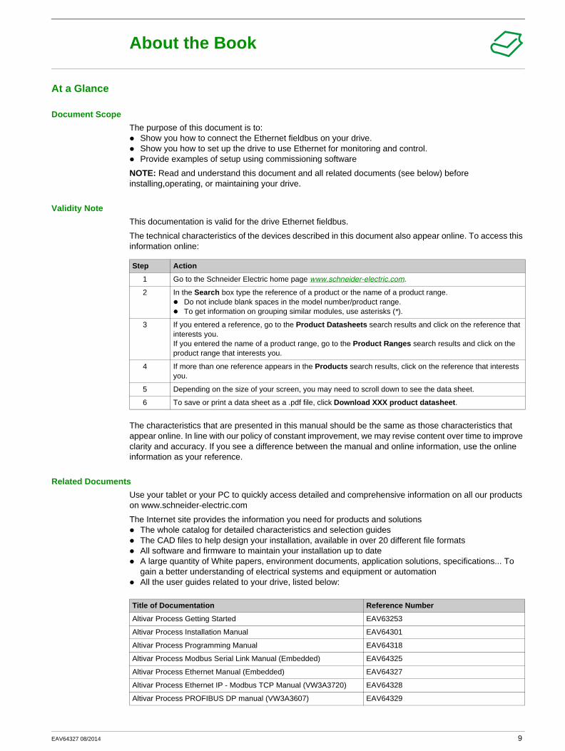
Document ScopeThe purpose of this document is to:
Show you how to connect the Ethernet fieldbus on your drive. Show you how to set up the drive to use Ethernet for monitoring and control.Provide examples of setup using commissioning software
NOTE: Read and understand this document and all related documents (see below) before installing,operating, or maintaining your drive.
Validity NoteThis documentation is valid for the drive Ethernet fieldbus.
The technical characteristics of the devices described in this document also appear online. To access this information online:
The characteristics that are presented in this manual should be the same as those characteristics that appear online. In line with our policy of constant improvement, we may revise content over time to improve clarity and accuracy. If you see a difference between the manual and online information, use the online information as your reference.
Related DocumentsUse your tablet or your PC to quickly access detailed and comprehensive information on all our products on www.schneider-electric.com
The Internet site provides the information you need for products and solutionsThe whole catalog for detailed characteristics and selection guidesThe CAD files to help design your installation, available in over 20 different file formatsAll software and firmware to maintain your installation up to dateA large quantity of White papers, environment documents, application solutions, specifications... To gain a better understanding of electrical systems and equipment or automationAll the user guides related to your drive, listed below:
Step Action
1 Go to the Schneider Electric home page www.schneider-electric.com.
2 In the Search box type the reference of a product or the name of a product range.Do not include blank spaces in the model number/product range.To get information on grouping similar modules, use asterisks (*).
3 If you entered a reference, go to the Product Datasheets search results and click on the reference that interests you.If you entered the name of a product range, go to the Product Ranges search results and click on the product range that interests you.
4 If more than one reference appears in the Products search results, click on the reference that interests you.
5 Depending on the size of your screen, you may need to scroll down to see the data sheet.
6 To save or print a data sheet as a .pdf file, click Download XXX product datasheet.
Title of Documentation Reference Number
Altivar Process Getting Started EAV63253
Altivar Process Installation Manual EAV64301
Altivar Process Programming Manual EAV64318
Altivar Process Modbus Serial Link Manual (Embedded) EAV64325
Altivar Process Ethernet Manual (Embedded) EAV64327
Altivar Process Ethernet IP - Modbus TCP Manual (VW3A3720) EAV64328
Altivar Process PROFIBUS DP manual (VW3A3607) EAV64329
EAV64327 08/2014 9

You can download these technical publications and other technical information from our website at www.schneider-electric.com.
Standards and TerminologyThe technical terms, terminology, and the corresponding descriptions in this manual normally use the terms or definitions in the relevant standards.
In the area of drive systems this includes, but is not limited to, terms such as error, error message, failure, fault, fault reset, protection, safe state, safety function, warning, warning message, and so on.
Among others, these standards include:IEC 61800 series: Adjustable speed electrical power drive systemsIEC 61508 Ed.2 series: Functional safety of electrical/electronic/programmable electronic safety-relatedEN 954-1 safety of machinery - Safety related parts of control systemsEN ISO 13849-1 & 2 safety of machinery - Safety related parts of control systems.IEC 61158 series: Industrial communication networks - Fieldbus specificationsIEC 61784 series: Industrial communication networks - ProfilesIEC 60204-1: Safety of machinery - Electrical equipment of machines – Part 1: General requirements
Altivar Process DeviceNet manual (VW3A3609) EAV64330
Altivar Process PROFINET manual (VW3A3627) EAV64333
Altivar Process CANopen Serial Link Manual (VW3A3608, 618, 628) EAV64331
Altivar Process Communication Parameters EAV64332
Altivar Process Safety Function Manual EAV64334
Title of Documentation Reference Number
10 EAV64327 08/2014

Presentation
Chapter 1Presentation
What Is in This Chapter?This chapter contains the following topics:
Topic Page
Hardware Overview 12
Software Overview 13
EAV64327 08/2014 11
Presentation
Hardware Overview
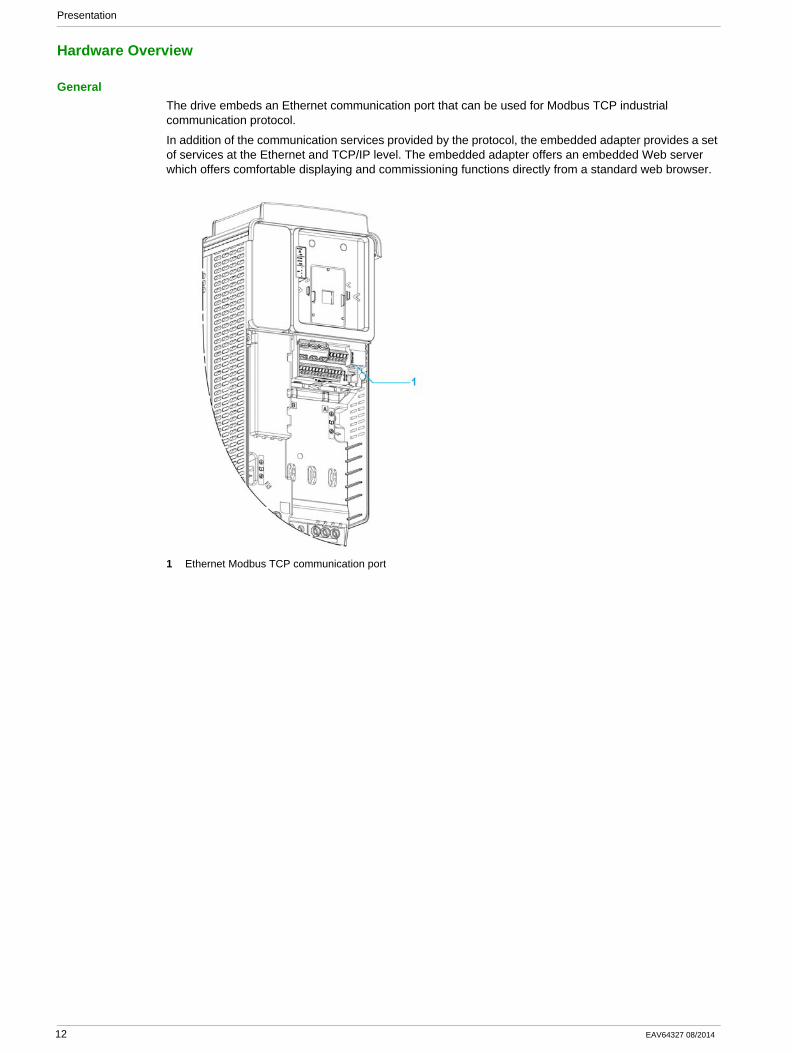
GeneralThe drive embeds an Ethernet communication port that can be used for Modbus TCP industrial communication protocol.
In addition of the communication services provided by the protocol, the embedded adapter provides a set of services at the Ethernet and TCP/IP level. The embedded adapter offers an embedded Web server which offers comfortable displaying and commissioning functions directly from a standard web browser.
1 Ethernet Modbus TCP communication port
12 EAV64327 08/2014
Presentation
Software Overview
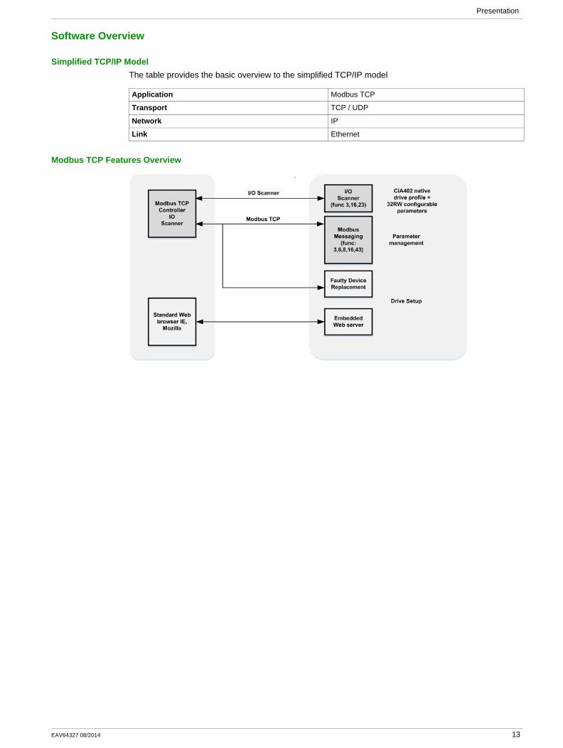
Simplified TCP/IP ModelThe table provides the basic overview to the simplified TCP/IP model
Modbus TCP Features Overview
Application Modbus TCP
Transport TCP / UDP
Network IP
Link Ethernet
EAV64327 08/2014 13

Presentation
14 EAV64327 08/2014

Basics
Chapter 2Basics
What Is in This Chapter?This chapter contains the following sections:
Section Topic Page
2.1 Introduction 16
2.2 Modbus TCP Features 22
EAV64327 08/2014 15
Basics
Introduction
Section 2.1Introduction
What Is in This Section?This section contains the following topics:
Topic Page
Overview 17
Network Layer Supported Functions/Protocols 18
TCP and UDP Protocol 20
16 EAV64327 08/2014
Basics
Overview
Modbus TCPThe Modbus application layer is standard. Thousands of manufacturers are already implementing this protocol. Many have already developed a Modbus TCP/IP connection and numerous products are currently available. With the simplicity of its protocol and the fast Ethernet throughput data rate of 100 Mbit/s, Modbus TCP/IP achieves excellent performance.
TCP/IP and Ethernet FeaturesThe product supports the following functions via:
Manual IP address assignmentAutomatic IP address assignment via BOOTP or DHCPAutomatic configuration data via FDRCommissioning via DTM-based commissioning softwareDiagnostics and configuration via integrated Web server
WebserverThe standard Web server (six languages) provides access to the following pages:
My dashboard: Customer defined view based on widgetsDisplayDiagnosticsDriveSetup
EAV64327 08/2014 17
Basics
Network Layer Supported Functions/Protocols
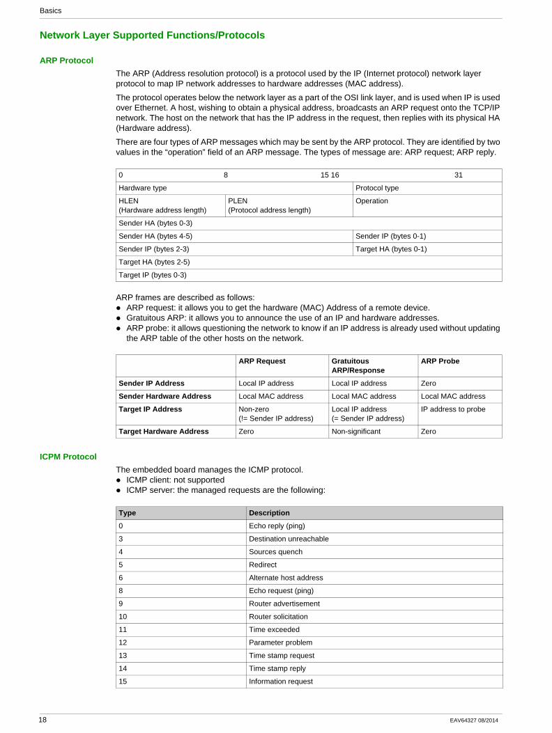
ARP ProtocolThe ARP (Address resolution protocol) is a protocol used by the IP (Internet protocol) network layer protocol to map IP network addresses to hardware addresses (MAC address).
The protocol operates below the network layer as a part of the OSI link layer, and is used when IP is used over Ethernet. A host, wishing to obtain a physical address, broadcasts an ARP request onto the TCP/IP network. The host on the network that has the IP address in the request, then replies with its physical HA (Hardware address).
There are four types of ARP messages which may be sent by the ARP protocol. They are identified by two values in the “operation” field of an ARP message. The types of message are: ARP request; ARP reply.
ARP frames are described as follows:ARP request: it allows you to get the hardware (MAC) Address of a remote device.Gratuitous ARP: it allows you to announce the use of an IP and hardware addresses.ARP probe: it allows questioning the network to know if an IP address is already used without updating the ARP table of the other hosts on the network.
ICPM ProtocolThe embedded board manages the ICMP protocol.
ICMP client: not supportedICMP server: the managed requests are the following:
0 8 15 16 31
Hardware type Protocol type
HLEN(Hardware address length)
PLEN(Protocol address length)
Operation
Sender HA (bytes 0-3)
Sender HA (bytes 4-5) Sender IP (bytes 0-1)
Sender IP (bytes 2-3) Target HA (bytes 0-1)
Target HA (bytes 2-5)
Target IP (bytes 0-3)
ARP Request Gratuitous ARP/Response
ARP Probe
Sender IP Address Local IP address Local IP address Zero
Sender Hardware Address Local MAC address Local MAC address Local MAC address
Target IP Address Non-zero (!= Sender IP address)
Local IP address (= Sender IP address)
IP address to probe
Target Hardware Address Zero Non-significant Zero
Type Description
0 Echo reply (ping)
3 Destination unreachable
4 Sources quench
5 Redirect
6 Alternate host address
8 Echo request (ping)
9 Router advertisement
10 Router solicitation
11 Time exceeded
12 Parameter problem
13 Time stamp request
14 Time stamp reply
15 Information request
18 EAV64327 08/2014
Basics
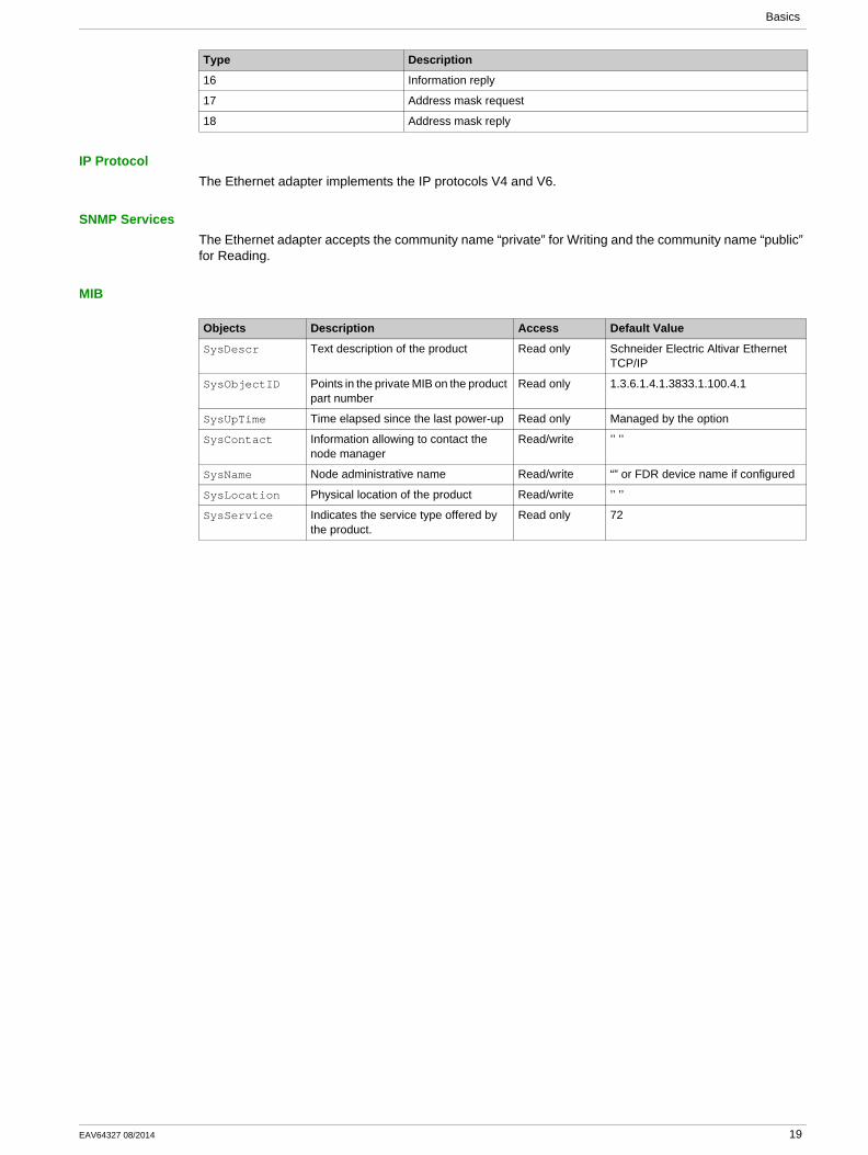
IP ProtocolThe Ethernet adapter implements the IP protocols V4 and V6.
SNMP ServicesThe Ethernet adapter accepts the community name “private” for Writing and the community name “public” for Reading.
MIB
16 Information reply
17 Address mask request
18 Address mask reply
Type Description
Objects Description Access Default Value
SysDescr Text description of the product Read only Schneider Electric Altivar Ethernet TCP/IP
SysObjectID Points in the private MIB on the product part number
Read only 1.3.6.1.4.1.3833.1.100.4.1
SysUpTime Time elapsed since the last power-up Read only Managed by the option
SysContact Information allowing to contact the node manager
Read/write ’’ ’’
SysName Node administrative name Read/write “” or FDR device name if configured
SysLocation Physical location of the product Read/write ’’ ’’
SysService Indicates the service type offered by the product.
Read only 72
EAV64327 08/2014 19
Basics
TCP and UDP Protocol
ConnectionsThe Ethernet adapter supports up to 32 concurrent TCP/IP and/or TCP/UDP connection.
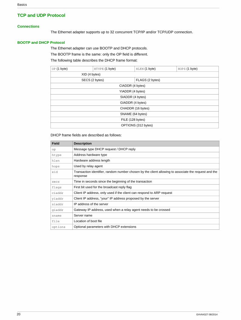
BOOTP and DHCP ProtocolThe Ethernet adapter can use BOOTP and DHCP protocols.
The BOOTP frame is the same: only the OP field is different.
The following table describes the DHCP frame format:
DHCP frame fields are described as follows:
OP (1 byte) HTYPE (1 byte) HLEN (1 byte) HOPS (1 byte)
XID (4 bytes)
SECS (2 bytes) FLAGS (2 bytes)
CIADDR (4 bytes)
YIADDR (4 bytes)
SIADDR (4 bytes)
GIADDR (4 bytes)
CHADDR (16 bytes)
SNAME (64 bytes)
FILE (128 bytes)
OPTIONS (312 bytes)
Field Description
op Message type DHCP request / DHCP reply
htype Address hardware type
hlen Hardware address length
hops Used by relay agent
xid Transaction identifier, random number chosen by the client allowing to associate the request and the response
secs Time in seconds since the beginning of the transaction
flags First bit used for the broadcast reply flag
ciaddr Client IP address, only used if the client can respond to ARP request
yiaddr Client IP address, “your” IP address proposed by the server
siaddr IP address of the server
giaddr Gateway IP address, used when a relay agent needs to be crossed
sname Server name
file Location of boot file
options Optional parameters with DHCP extensions
20 EAV64327 08/2014
Basics
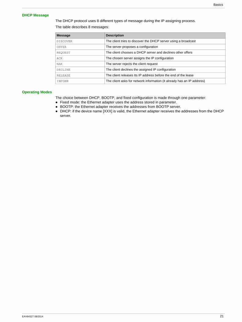
DHCP MessageThe DHCP protocol uses 8 different types of message during the IP assigning process.
The table describes 8 messages:
Operating ModesThe choice between DHCP, BOOTP, and fixed configuration is made through one parameter:
Fixed mode: the Ethernet adapter uses the address stored in parameter.BOOTP: the Ethernet adapter receives the addresses from BOOTP server.DHCP: if the device name [XXX] is valid, the Ethernet adapter receives the addresses from the DHCP server.
Message Description
DISCOVER The client tries to discover the DHCP server using a broadcast
OFFER The server proposes a configuration
REQUEST The client chooses a DHCP server and declines other offers
ACK The chosen server assigns the IP configuration
NAK The server rejects the client request
DECLINE The client declines the assigned IP configuration
RELEASE The client releases Its IP address before the end of the lease
INFORM The client asks for network information (it already has an IP address)
EAV64327 08/2014 21
Basics
Modbus TCP Features
Section 2.2Modbus TCP Features
What Is in This Section?This section contains the following topics:
Topic Page
Modbus TCP Frames 23
Modbus TCP Servers 24
Supported Modbus TCP Functions 25
Application Profile with Modbus TCP 26
22 EAV64327 08/2014
Basics
Modbus TCP Frames
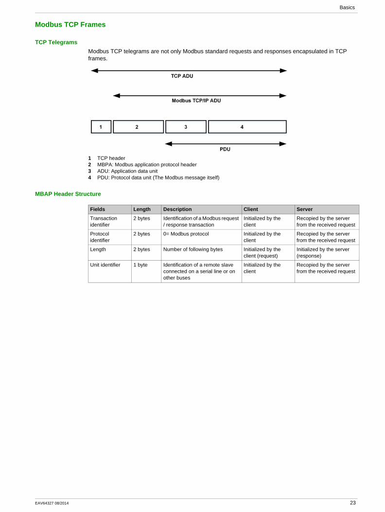
TCP TelegramsModbus TCP telegrams are not only Modbus standard requests and responses encapsulated in TCP frames.
1 TCP header2 MBPA: Modbus application protocol header3 ADU: Application data unit4 PDU: Protocol data unit (The Modbus message itself)
MBAP Header Structure
Fields Length Description Client Server
Transaction identifier
2 bytes Identification of a Modbus request / response transaction
Initialized by the client
Recopied by the server from the received request
Protocol identifier
2 bytes 0= Modbus protocol Initialized by the client
Recopied by the server from the received request
Length 2 bytes Number of following bytes Initialized by the client (request)
Initialized by the server (response)
Unit identifier 1 byte Identification of a remote slave connected on a serial line or on other buses
Initialized by the client
Recopied by the server from the received request
EAV64327 08/2014 23

Basics
Modbus TCP Servers
Overview
Unit ID Modbus TCP server Accessible parameters
0/248 Variable speed drive See the file related to drive communication parameters.
255 Drive I/O scanner See I/O scanner setting (see page 25)
24 EAV64327 08/2014
Basics
Supported Modbus TCP Functions
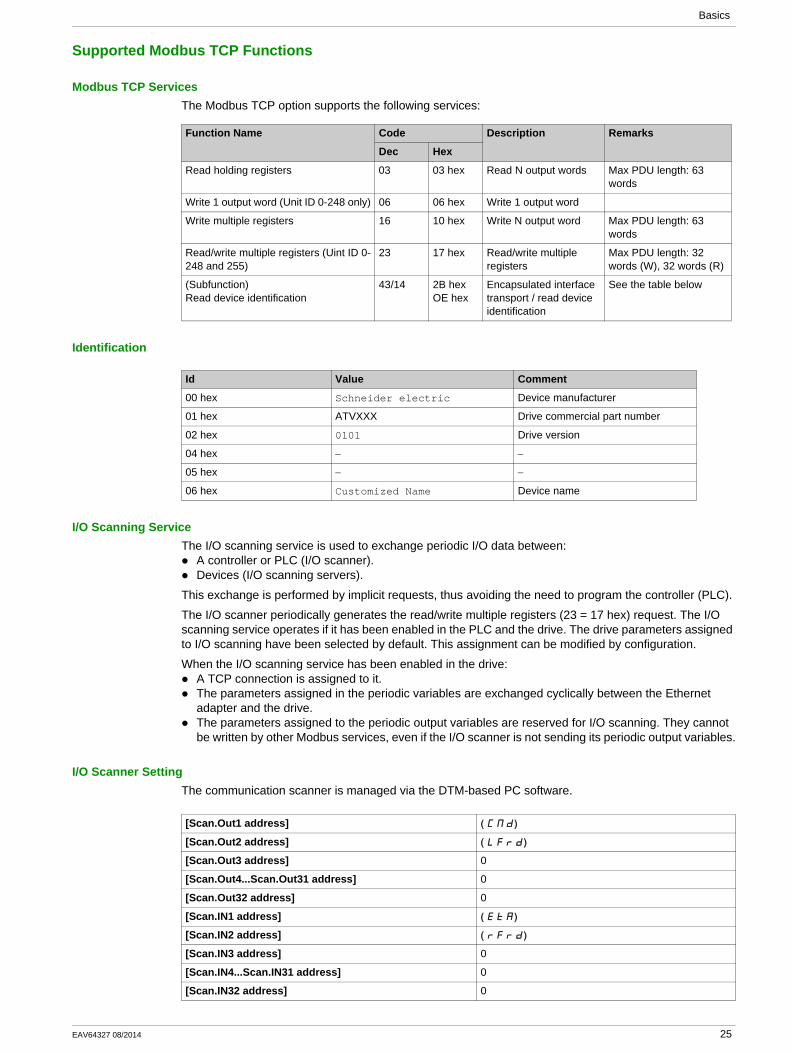
Modbus TCP ServicesThe Modbus TCP option supports the following services:
Identification
I/O Scanning ServiceThe I/O scanning service is used to exchange periodic I/O data between:
A controller or PLC (I/O scanner).Devices (I/O scanning servers).
This exchange is performed by implicit requests, thus avoiding the need to program the controller (PLC).
The I/O scanner periodically generates the read/write multiple registers (23 = 17 hex) request. The I/O scanning service operates if it has been enabled in the PLC and the drive. The drive parameters assigned to I/O scanning have been selected by default. This assignment can be modified by configuration.
When the I/O scanning service has been enabled in the drive:A TCP connection is assigned to it.The parameters assigned in the periodic variables are exchanged cyclically between the Ethernet adapter and the drive.The parameters assigned to the periodic output variables are reserved for I/O scanning. They cannot be written by other Modbus services, even if the I/O scanner is not sending its periodic output variables.
I/O Scanner SettingThe communication scanner is managed via the DTM-based PC software.
Function Name Code Description Remarks
Dec Hex
Read holding registers 03 03 hex Read N output words Max PDU length: 63 words
Write 1 output word (Unit ID 0-248 only) 06 06 hex Write 1 output word
Write multiple registers 16 10 hex Write N output word Max PDU length: 63 words
Read/write multiple registers (Uint ID 0-248 and 255)
23 17 hex Read/write multiple registers
Max PDU length: 32 words (W), 32 words (R)
(Subfunction)Read device identification
43/14 2B hex OE hex
Encapsulated interface transport / read device identification
See the table below
Id Value Comment
00 hex Schneider electric Device manufacturer
01 hex ATVXXX Drive commercial part number
02 hex 0101 Drive version
04 hex − −
05 hex − −
06 hex Customized Name Device name
[Scan.Out1 address] ( )CMd
[Scan.Out2 address] ( )LFrd
[Scan.Out3 address] 0
[Scan.Out4...Scan.Out31 address] 0
[Scan.Out32 address] 0
[Scan.IN1 address] ( )EtA
[Scan.IN2 address] ( )rFrd
[Scan.IN3 address] 0
[Scan.IN4...Scan.IN31 address] 0
[Scan.IN32 address] 0
EAV64327 08/2014 25

Basics
Application Profile with Modbus TCP
DescriptionThe profiles managed with the drive when it is controlled through Modbus TCP are:
Native profile (CiA402 - IEC 61800-7),I/O profile.
For details, refer to CiA®402 - IEC61800-7 functional profile (see page 63)
26 EAV64327 08/2014
Hardware Setup
Chapter 3Hardware Setup
What Is in This Chapter?This chapter contains the following topics:
Topic Page
Hardware Presentation 28
Firmware Version 29
Connection to the Adapter 30
Electrical Installation 31
Cable Routing Practice 32
EAV64327 08/2014 27
Hardware Setup
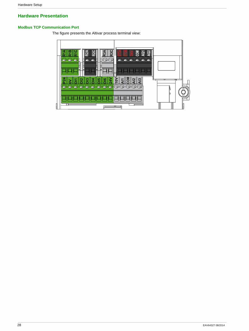
Hardware Presentation
Modbus TCP Communication PortThe figure presents the Altivar process terminal view:
28 EAV64327 08/2014

Hardware Setup
Firmware Version
CompatibilityThe drive firmware and embedded communication adapter are provided in a common package for updating the drive.
EAV64327 08/2014 29
Hardware Setup
Connection to the Adapter
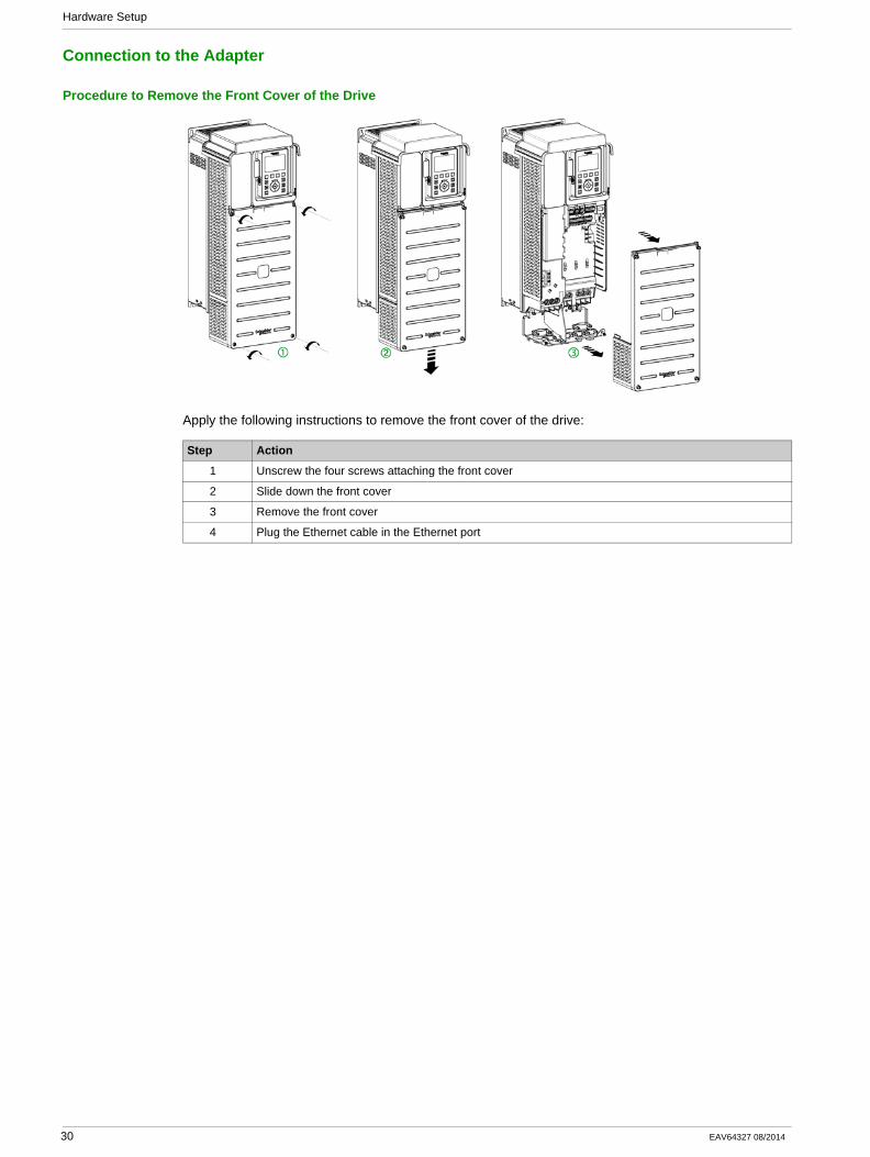
Procedure to Remove the Front Cover of the Drive
Apply the following instructions to remove the front cover of the drive:
Step Action
1 Unscrew the four screws attaching the front cover
2 Slide down the front cover
3 Remove the front cover
4 Plug the Ethernet cable in the Ethernet port
30 EAV64327 08/2014
Hardware Setup
Electrical Installation
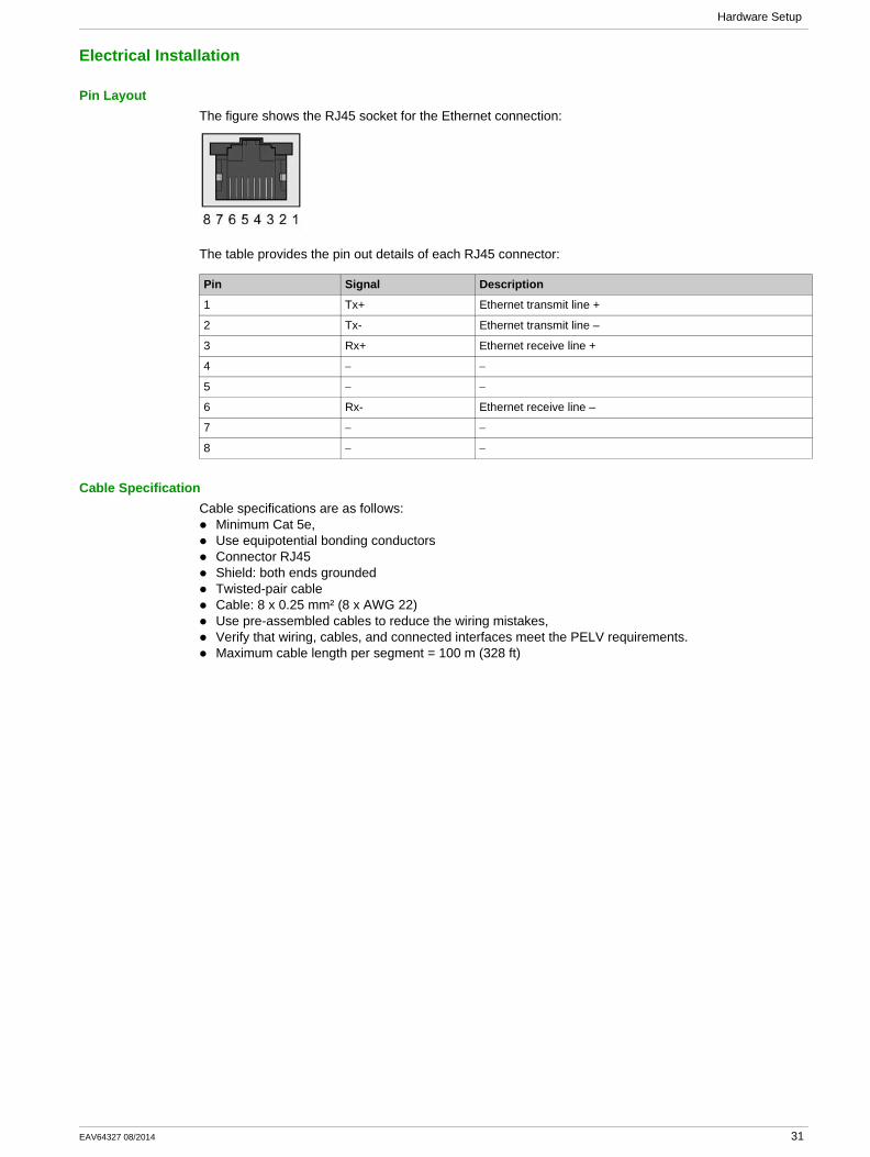
Pin LayoutThe figure shows the RJ45 socket for the Ethernet connection:
The table provides the pin out details of each RJ45 connector:
Cable SpecificationCable specifications are as follows:
Minimum Cat 5e,Use equipotential bonding conductorsConnector RJ45Shield: both ends groundedTwisted-pair cableCable: 8 x 0.25 mm² (8 x AWG 22)Use pre-assembled cables to reduce the wiring mistakes,Verify that wiring, cables, and connected interfaces meet the PELV requirements.Maximum cable length per segment = 100 m (328 ft)
Pin Signal Description
1 Tx+ Ethernet transmit line +
2 Tx- Ethernet transmit line –
3 Rx+ Ethernet receive line +
4 − −
5 − −
6 Rx- Ethernet receive line –
7 − −
8 − −
EAV64327 08/2014 31
Hardware Setup
Cable Routing Practice
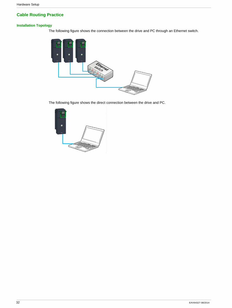
Installation TopologyThe following figure shows the connection between the drive and PC through an Ethernet switch.
The following figure shows the direct connection between the drive and PC.
32 EAV64327 08/2014
Software Setup
Chapter 4Software Setup
What Is in This Chapter?This chapter contains the following sections:
Section Topic Page
4.1 Basic Settings 34
4.2 Additional Settings 51
4.3 Fast Device Replacement 56
4.4 Communication Profile 63
4.5 Embedded Webserver 80
EAV64327 08/2014 33
Software Setup
Basic Settings
Section 4.1Basic Settings
What Is in This Section?This section contains the following topics:
Topic Page
IP Parameter Settings 35
[Device Name] ( )PAn 36
[IP mode Eth Embd] ( )IM00 37
[IP Eth Embd] (IC01) (IC02) (IC03) (IC04) 38
[IP Mask Eth Embd] (IM01) (IM02) (IM03) (IM04) 39
[IP Gate Eth Embd] (IG01) (IG02) (IG03) (IG04) 40
[MAC @] (MAC) 41
[ETH emb Rx frames] ( )ErXE 42
[ETH emb Tx frames] ( )EtXE 43
[ETH emb error frames] ( )EErE 44
[Ethernet Rate Data] ( )ArdE 45
[Ethernet Embd cmd.] ( )CMd5 46
[Ethernet Embd Ref Freq] ( )LFr5 47
[Enable Web Services] ( )EWEE 48
[Reset EmbWeb Passwd] ( )rWPE 49
[Ethernet Timeout] ( )ttOb 50
34 EAV64327 08/2014
Software Setup
IP Parameter Settings
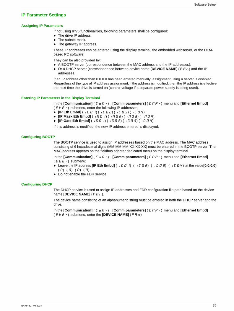
Assigning IP ParametersIf not using IPV6 functionalities, following parameters shall be configured:
The drive IP address.The subnet mask.The gateway IP address.
These IP addresses can be entered using the display terminal, the embedded webserver, or the DTM-based PC software.
They can be also provided by:A BOOTP server (correspondence between the MAC address and the IP addresses).Or a DHCP server (correspondence between device name [DEVICE NAME] (PAn) and the IP addresses).
If an IP address other than 0.0.0.0 has been entered manually, assignment using a server is disabled. Regardless of the type of IP address assignment, if the address is modified, then the IP address is effective the next time the drive is turned on (control voltage if a separate power supply is being used).
Entering IP Parameters in the Display TerminalIn the [Communication] ( )COM- , [Comm parameters] ( )CMP- menu and [Ethernet Embd] ( )EtE- submenu, enter the following IP addresses:
[IP Eth Embd] (IC01) (IC02) (IC03) (IC04)[IP Mask Eth Embd] (IM01) (IM02) (IM03) (IM04),[IP Gate Eth Embd] (IG01) (IG02) (IG03) (IG04).
If this address is modified, the new IP address entered is displayed.
Configuring BOOTPThe BOOTP service is used to assign IP addresses based on the MAC address. The MAC address consisting of 6 hexadecimal digits (MM-MM-MM-XX-XX-XX) must be entered in the BOOTP server. The MAC address appears on the fieldbus adapter dedicated menu on the display terminal.
In the [Communication] ( )COM- , [Comm parameters] ( )CMP- menu and [Ethernet Embd] ( )EtE- submenu:
Leave the IP address [IP Eth Embd] ( ) ( ) ( ) ( )IC01 IC02 IC03 IC04 at the value[0.0.0.0] ( ) ( ) ( ) ( )0 0 0 0 .Do not enable the FDR service.
Configuring DHCPThe DHCP service is used to assign IP addresses and FDR configuration file path based on the device name [DEVICE NAME] (PAn).
The device name consisting of an alphanumeric string must be entered in both the DHCP server and the drive.
In the [Communication] ( )COM- , [Comm parameters] ( )CMP- menu and [Ethernet Embd] ( )EtE- submenu, enter the [DEVICE NAME] (PAn)
EAV64327 08/2014 35
Software Setup
[Device Name] ( )PAn
About This ParameterThis parameter is used set the device name.
AccessThis parameter is accessible via [Communication] ( )COM- , [Comm parameters] ( )CMP- menu and [Ethernet Embd] ( )EtE- submenu.
This is a read/write parameter
Possible SettingsThe FDR (Fast Device Replacement) service is based on identification of the device by a Device Name. In the case of the Altivar drive, this is represented by the [Device Name] ( )PAn parameter. Verify that all the network devices have different Device Name.
36 EAV64327 08/2014
Software Setup
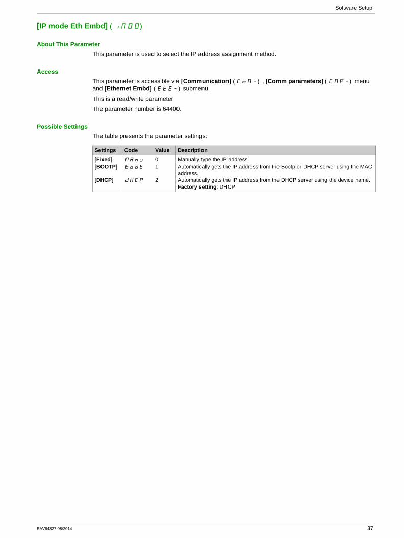
[IP mode Eth Embd] ( )IM00
About This ParameterThis parameter is used to select the IP address assignment method.
AccessThis parameter is accessible via [Communication] ( )COM- , [Comm parameters] ( )CMP- menu and [Ethernet Embd] ( )EtE- submenu.
This is a read/write parameter
The parameter number is 64400.
Possible SettingsThe table presents the parameter settings:
Settings Code Value Description
[Fixed][BOOTP]
[DHCP]
MAnU
bOOt
dHCP
01
2
Manually type the IP address.Automatically gets the IP address from the Bootp or DHCP server using the MAC address.Automatically gets the IP address from the DHCP server using the device name.Factory setting: DHCP
EAV64327 08/2014 37
Software Setup
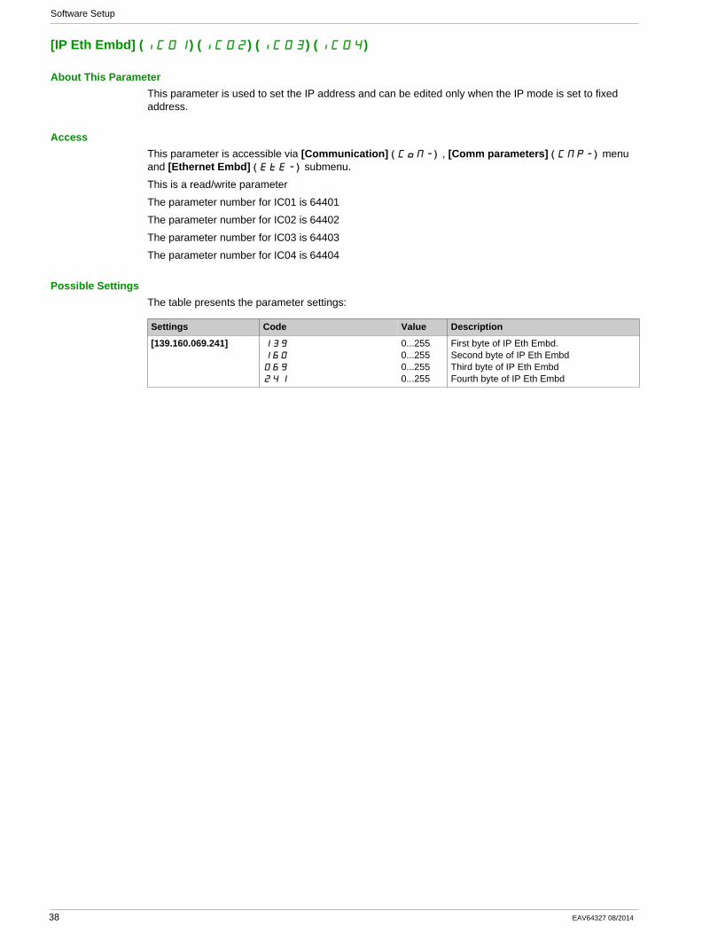
[IP Eth Embd] (IC01) (IC02) (IC03) (IC04)
About This ParameterThis parameter is used to set the IP address and can be edited only when the IP mode is set to fixed address.
AccessThis parameter is accessible via [Communication] ( )COM- , [Comm parameters] ( )CMP- menu and [Ethernet Embd] ( )EtE- submenu.
This is a read/write parameter
The parameter number for IC01 is 64401
The parameter number for IC02 is 64402
The parameter number for IC03 is 64403
The parameter number for IC04 is 64404
Possible SettingsThe table presents the parameter settings:
Settings Code Value Description
[139.160.069.241] 139
160
069
241
0...2550...2550...2550...255
First byte of IP Eth Embd.Second byte of IP Eth EmbdThird byte of IP Eth EmbdFourth byte of IP Eth Embd
38 EAV64327 08/2014
Software Setup
[IP Mask Eth Embd] (IM01) (IM02) (IM03) (IM04)
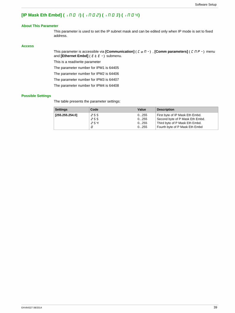
About This ParameterThis parameter is used to set the IP subnet mask and can be edited only when IP mode is set to fixed address.
AccessThis parameter is accessible via [Communication] ( )COM- , [Comm parameters] ( )CMP- menu and [Ethernet Embd] ( )EtE- submenu.
This is a read/write parameter
The parameter number for IPM1 is 64405
The parameter number for IPM2 is 64406
The parameter number for IPM3 is 64407
The parameter number for IPM4 is 64408
Possible SettingsThe table presents the parameter settings:
Settings Code Value Description
[255.255.254.0] 255
255
254
0
0...2550...2550...2550...255
First byte of IP Mask Eth Embd.Second byte of P Mask Eth Embd.Third byte of P Mask Eth Embd.Fourth byte of P Mask Eth Embd
EAV64327 08/2014 39
Software Setup
[IP Gate Eth Embd] (IG01) (IG02) (IG03) (IG04)
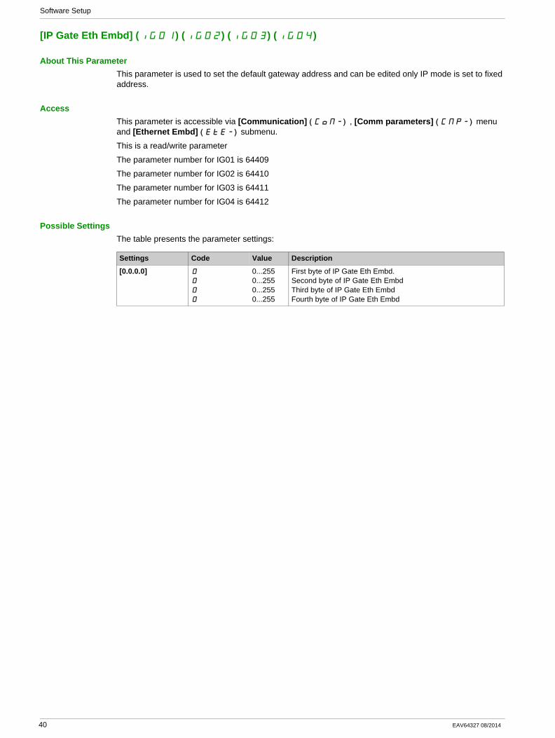
About This ParameterThis parameter is used to set the default gateway address and can be edited only IP mode is set to fixed address.
AccessThis parameter is accessible via [Communication] ( )COM- , [Comm parameters] ( )CMP- menu and [Ethernet Embd] ( )EtE- submenu.
This is a read/write parameter
The parameter number for IG01 is 64409
The parameter number for IG02 is 64410
The parameter number for IG03 is 64411
The parameter number for IG04 is 64412
Possible SettingsThe table presents the parameter settings:
Settings Code Value Description
[0.0.0.0] 0
0
0
0
0...2550...2550...2550...255
First byte of IP Gate Eth Embd.Second byte of IP Gate Eth EmbdThird byte of IP Gate Eth EmbdFourth byte of IP Gate Eth Embd
40 EAV64327 08/2014
Software Setup
[MAC @] (MAC)
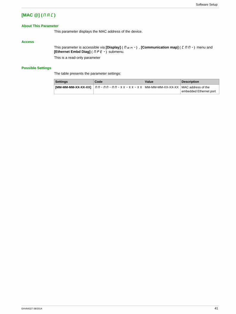
About This ParameterThis parameter displays the MAC address of the device.
AccessThis parameter is accessible via [Display] ( )MON- , [Communication map] ( )CMM- menu and [Ethernet Embd Diag] ( )MPE- submenu.
This is a read-only parameter
Possible SettingsThe table presents the parameter settings:
Settings Code Value Description
[MM-MM-MM-XX-XX-XX] MM-MM-MM-XX-XX-XX MM-MM-MM-XX-XX-XX MAC address of the embedded Ethernet port
EAV64327 08/2014 41

Software Setup
[ETH emb Rx frames] ( )ErXE
About This ParameterThis parameter displays the Ethernet embedded received frames counter
AccessThis parameter is accessible via [Display] ( )MON- , [Communication map] ( )CMM- menu and [Ethernet Embd Diag] ( )MPE- submenu.
This is a read-only parameter
The parameter numbers is 64416
42 EAV64327 08/2014

Software Setup
[ETH emb Tx frames] ( )EtXE
About This ParameterThis parameter displays the Ethernet embedded transmitted frames counter
AccessThis parameter is accessible via [Display] ( )MON- , [Communication map] ( )CMM- menu and [Ethernet Embd Diag] ( )MPE- submenu.
This is a read-only parameter
The parameter numbers is 64418
EAV64327 08/2014 43

Software Setup
[ETH emb error frames] ( )EErE
About This ParameterThis parameter displays the Ethernet embedded error frames counter
AccessThis parameter is accessible via [Display] ( )MON- , [Communication map] ( )CMM- menu and [Ethernet Embd Diag] ( )MPE- submenu.
This is a read-only parameter
The parameter numbers is 64420
44 EAV64327 08/2014
Software Setup
[Ethernet Rate Data] ( )ArdE
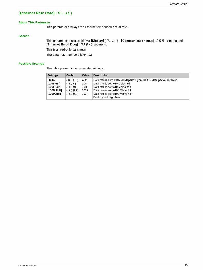
About This ParameterThis parameter displays the Ethernet embedded actual rate.
AccessThis parameter is accessible via [Display] ( )MON- , [Communication map] ( )CMM- menu and [Ethernet Embd Diag] ( )MPE- submenu.
This is a read-only parameter
The parameter numbers is 64413
Possible SettingsThe table presents the parameter settings:
Settings Code Value Description
[Auto][10M.Full][10M.Half][100M.Full][100M.Half]
( )AUtO
( )10F
( )10H
( )100F
( )100H
Auto10F10H100F100H
Data rate is auto detected depending on the first data packet received.Data rate is set to10 Mbit/s fullData rate is set to10 Mbit/s halfData rate is set to100 Mbit/s fullData rate is set to100 Mbit/s halfFactory setting: Auto
EAV64327 08/2014 45

Software Setup
[Ethernet Embd cmd.] ( )CMd5
About This ParameterThis parameter displays the command word built with Ethernet embedded source (same as CMD).
AccessThis parameter is accessible via [Display] ( )MON- , [Communication map] ( )CMM- menu and [Command word image] ( )CWI- submenu.
This is a read-only parameter
The parameter numbers is 8515
46 EAV64327 08/2014

Software Setup
[Ethernet Embd Ref Freq] ( )LFr5
About This ParameterThis parameter displays the reference frequency built with Ethernet embedded source (same as LFr).
AccessThis parameter is accessible via [Display] ( )MON- , [Communication map] ( )CMM- menu and [Command word image] ( )CWI- submenu.
This is a read-only parameter
The parameter numbers is 8525
EAV64327 08/2014 47
Software Setup
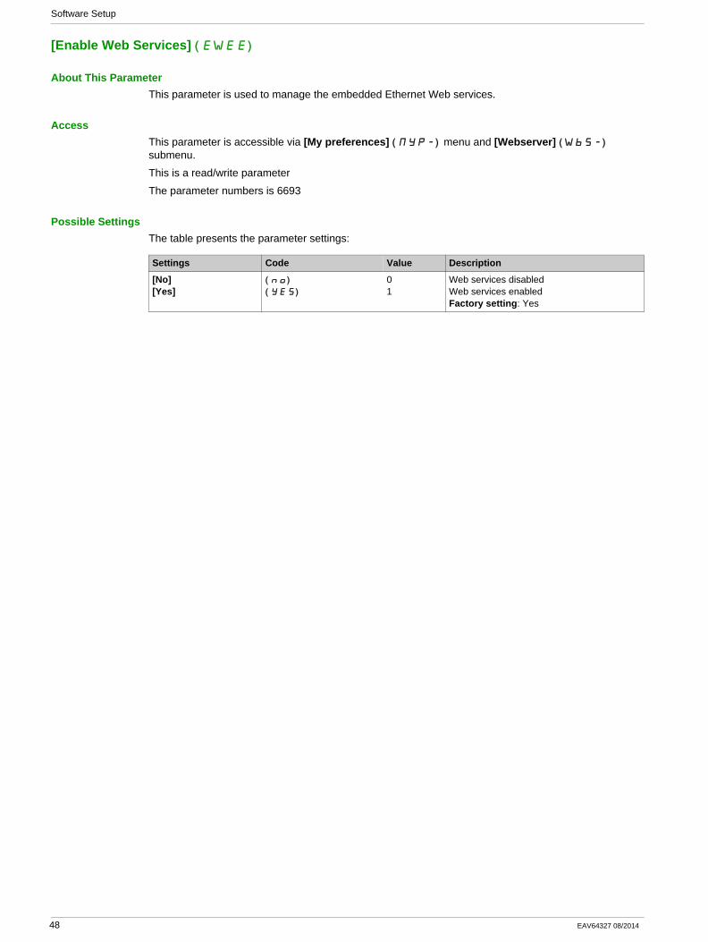
[Enable Web Services] ( )EWEE
About This ParameterThis parameter is used to manage the embedded Ethernet Web services.
AccessThis parameter is accessible via [My preferences] ( )MYP- menu and [Webserver] ( )WbS- submenu.
This is a read/write parameter
The parameter numbers is 6693
Possible SettingsThe table presents the parameter settings:
Settings Code Value Description
[No][Yes]
( )no
( )yes
01
Web services disabledWeb services enabledFactory setting: Yes
48 EAV64327 08/2014
Software Setup
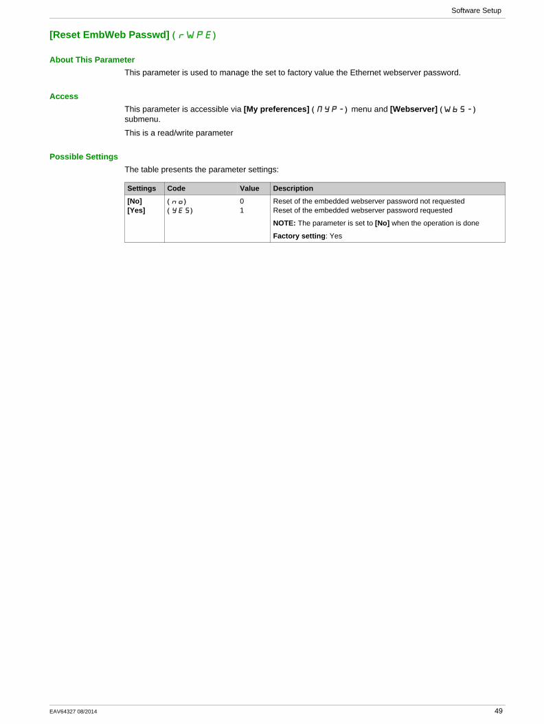
[Reset EmbWeb Passwd] ( )rWPE
About This ParameterThis parameter is used to manage the set to factory value the Ethernet webserver password.
AccessThis parameter is accessible via [My preferences] ( )MYP- menu and [Webserver] ( )WbS- submenu.
This is a read/write parameter
Possible SettingsThe table presents the parameter settings:
Settings Code Value Description
[No][Yes]
( )no
( )yes
01
Reset of the embedded webserver password not requestedReset of the embedded webserver password requested
NOTE: The parameter is set to [No] when the operation is done
Factory setting: Yes
EAV64327 08/2014 49
Software Setup
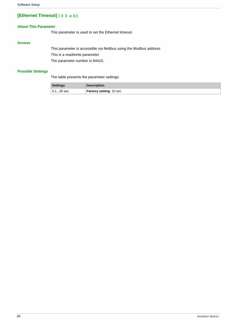
[Ethernet Timeout] ( )ttOb
About This ParameterThis parameter is used to set the Ethernet timeout.
AccessThis parameter is accessible via fieldbus using the Modbus address.
This is a read/write parameter
The parameter number is 64415.
Possible SettingsThe table presents the parameter settings:
Settings Description
0.1...30 sec Factory setting: 10 sec
50 EAV64327 08/2014
Software Setup
Additional Settings
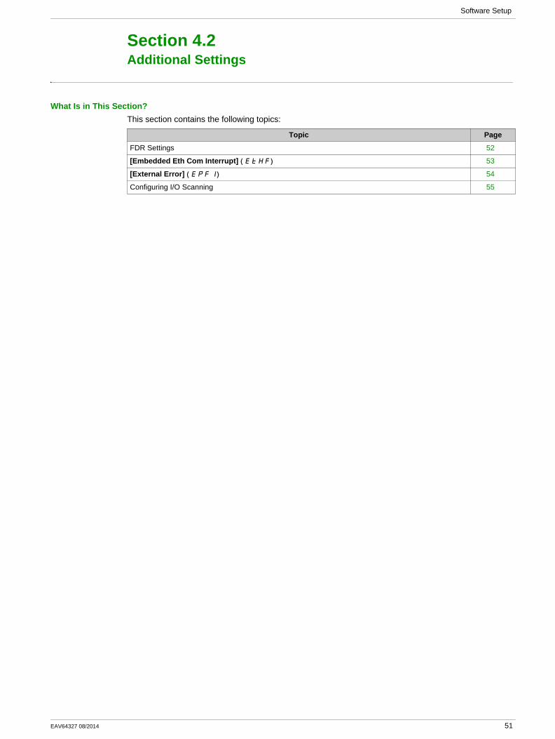
Section 4.2Additional Settings
What Is in This Section?This section contains the following topics:
Topic Page
FDR Settings 52
[Embedded Eth Com Interrupt] ( )EtHF 53
[External Error] ( )EPF1 54
Configuring I/O Scanning 55
EAV64327 08/2014 51
Software Setup
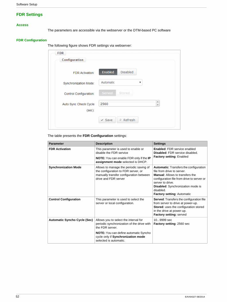
FDR Settings
AccessThe parameters are accessible via the webserver or the DTM-based PC software
FDR ConfigurationThe following figure shows FDR settings via webserver:
The table presents the FDR Configuration settings:
Parameter Description Settings
FDR Activation This parameter is used to enable or disable the FDR service
NOTE: You can enable FDR only if the IP assignment mode selected is DHCP.
Enabled: FDR service enabledDisabled: FDR service disabled.Factory setting: Enabled
Synchronization Mode Allows to manage the periodic saving of the configuration to FDR server, or manually transfer configuration between drive and FDR server
Automatic: Transfers the configuration file from drive to server.Manual: Allows to transfers the configuration file from drive to server or server to drive.Disabled: Synchronization mode is disabled.Factory setting: Automatic
Control Configuration This parameter is used to select the server or local configuration.
Served: Transfers the configuration file from server to drive at power-up.Stored: uses the configuration stored in the drive at power-up.Factory setting: served
Automatic Syncho Cycle (Sec) Allows you to select the interval for periodic synchronization of the drive with the FDR server.
NOTE: You can define automatic Syncho cycle only if Synchronization mode selected is automatic.
10...9999 secFactory setting: 2560 sec
52 EAV64327 08/2014
Software Setup
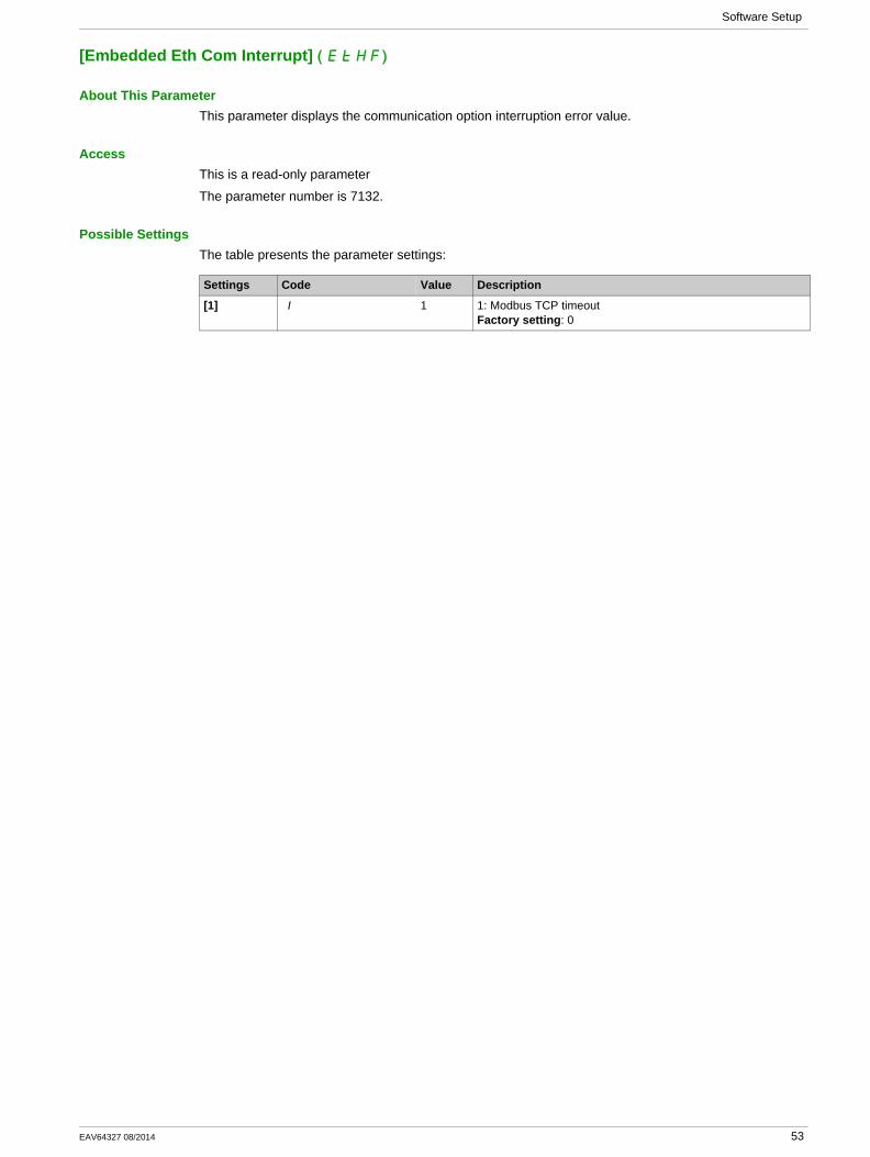
[Embedded Eth Com Interrupt] ( )EtHF
About This ParameterThis parameter displays the communication option interruption error value.
AccessThis is a read-only parameter
The parameter number is 7132.
Possible SettingsThe table presents the parameter settings:
Settings Code Value Description
[1] 1 1 1: Modbus TCP timeoutFactory setting: 0
EAV64327 08/2014 53
Software Setup
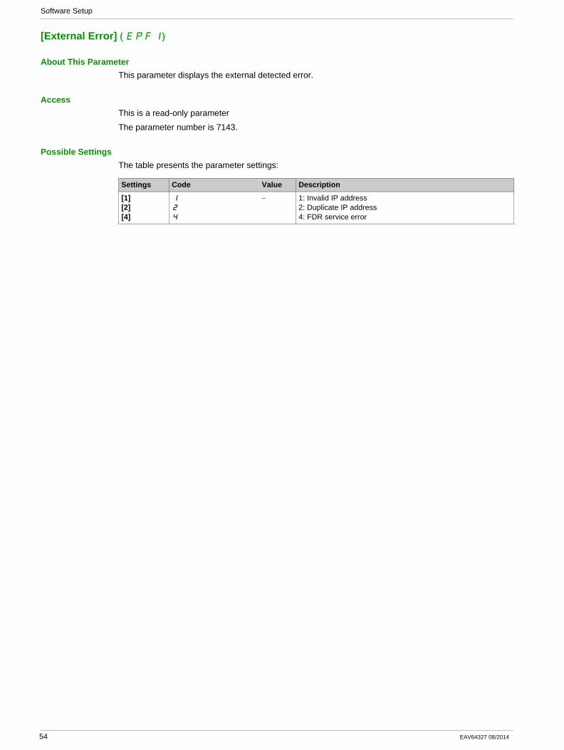
[External Error] ( )EPF1
About This ParameterThis parameter displays the external detected error.
AccessThis is a read-only parameter
The parameter number is 7143.
Possible SettingsThe table presents the parameter settings:
Settings Code Value Description
[1][2][4]
1
2
4
− 1: Invalid IP address2: Duplicate IP address4: FDR service error
54 EAV64327 08/2014

Software Setup
Configuring I/O Scanning
DescriptionThe drive I/O scanning service can be enabled or disabled with the DTM-based PC software.
It is not possible to modify the assignment of the I/O scanning periodic variables using the display terminal. To configure I/O scanning, use the DTM-based PC software.
EAV64327 08/2014 55
Software Setup
Fast Device Replacement
Section 4.3Fast Device Replacement
What Is in This Section?This section contains the following topics:
Topic Page
Presentation 57
Startup Detailed Behavior 58
FDR Operation Behavior 59
Local Configuration 60
Downloaded Configuration 61
56 EAV64327 08/2014
Software Setup
Presentation
FDR ServiceThe FDR (Fast Device Replacement) service is used to simplify the maintenance of drives connected on the Ethernet network. In the event of drive not functioning correctly, this service automatically reconfigures its replacement.
The new drive (FDR client) retrieves:Its IP addresses and the FDR file path from a DHCP serverThe FDR file from an FTP server, if the drive is not configured in local configuration
In practice, the DHCP server and the FTP server are the same device (PAC M580, M340 PLC, or dedicated PCs).
The FDR file contains:The Ethernet parameters (configuration of I/O scanning, FDR, and so on)The drive parameters (drive, functions, application, and so on)
The FDR service is based on identification of the device by a Device Name. In the case of the Altivar process drive, this is represented by the [DEVICE NAME] ( )PAn parameter.
The configuration of the FDR service is accessible via embedded webserver or DTM-based software.
NOTE: Check that all the network devices have different Device Name.
NOTE: The FDR server controls duplication of Device Name (it does not assign an IP address that has already been assigned and is active).
If the same IP address is supplied on 2 devices, the second should trigger an IP address duplication (network management detected error which triggers an [External Error] ( )EPF1 by default).
If the FDR service has been enabled, the Ethernet adapter attempts to restore its IP addresses on each power-up. Each time the procedure has detected error, the Ethernet adapter reiterates its FDR requests (DHCP).
Where the configuration also needs to be downloaded by the FDR server:
After assigning the Ethernet card IP addresses, if the configuration download has detected error, the Ethernet card detects a network management detected error (triggers an [External Error] ( )EPF1 by default).
EAV64327 08/2014 57
Software Setup
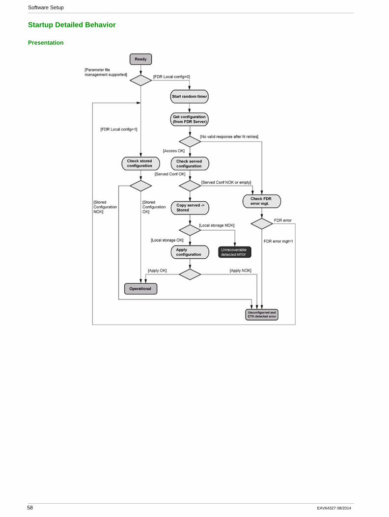
Startup Detailed Behavior
Presentation
58 EAV64327 08/2014
Software Setup
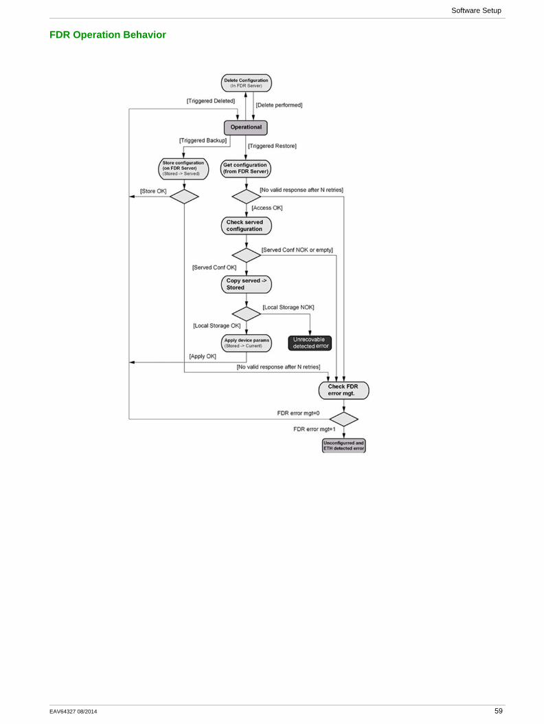
FDR Operation Behavior
EAV64327 08/2014 59
Software Setup
Local Configuration
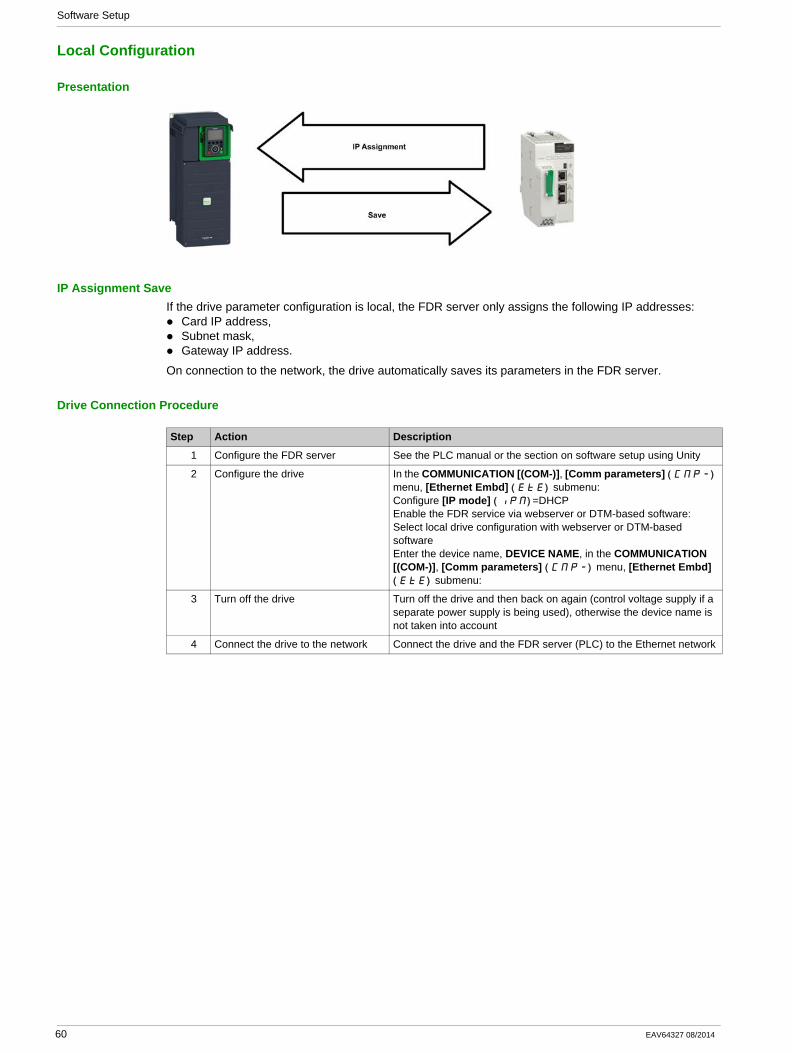
Presentation
IP Assignment SaveIf the drive parameter configuration is local, the FDR server only assigns the following IP addresses:
Card IP address,Subnet mask,Gateway IP address.
On connection to the network, the drive automatically saves its parameters in the FDR server.
Drive Connection Procedure
Step Action Description
1 Configure the FDR server See the PLC manual or the section on software setup using Unity
2 Configure the drive In the COMMUNICATION [(COM-)], [Comm parameters] ( )CMP- menu, [Ethernet Embd] ( )EtE submenu:Configure [IP mode] ( )IPM =DHCPEnable the FDR service via webserver or DTM-based software:Select local drive configuration with webserver or DTM-based softwareEnter the device name, DEVICE NAME, in the COMMUNICATION [(COM-)], [Comm parameters] ( )CMP- menu, [Ethernet Embd] ( )EtE submenu:
3 Turn off the drive Turn off the drive and then back on again (control voltage supply if a separate power supply is being used), otherwise the device name is not taken into account
4 Connect the drive to the network Connect the drive and the FDR server (PLC) to the Ethernet network
60 EAV64327 08/2014
Software Setup
Downloaded Configuration
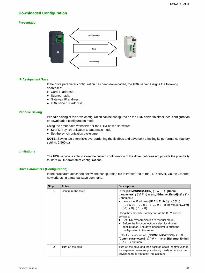
Presentation
IP Assignment SaveIf the drive parameter configuration has been downloaded, the FDR server assigns the following addresses:
Card IP address,Subnet mask,Gateway IP address,FDR server IP address.
Periodic SavingPeriodic saving of the drive configuration can be configured on the FDR server in either local configuration or downloaded configuration mode
Using the embedded webserver or the DTM-based software:Set FDR synchronization to automatic modeSet the synchronization cycle time
NOTE: Saving too often risks overburdening the fieldbus and adversely affecting its performance (factory setting: 2.560 s.).
LimitationsThe FDR service is able to store the current configuration of the drive, but does not provide the possibility to store multi-parameters configurations.
Drive Parameters (Configuration)In the procedure described below, the configuration file is transferred to the FDR server, via the Ethernet network, using a manual save command.
Step Action Description
1 Configure the drive In the [COMMUNICATION] ( )COM- , [Comm parameters] ( )CMP- menu, [Ethernet Embd] ( EtE-
) submenu:Leave the IP address [IP Eth Embd] ( ) IC01
( ) ( ) ( )IC02 IC03 IC04 at the value [0.0.0.0] ( ) ( ) ( ) ( )0 0 0 0
Using the embedded webserver or the DTM-based software:
Set FDR synchronization to manual mode.Before the first connection, select local drive configuration. The drive needs first to push the configuration to the server.
Enter the device name, [COMMUNICATION] ( )COM- , [Comm parameters] ( )CMP- menu, [Ethernet Embd] ( )EtE- submenu.
2 Turn off the drive Turn off the drive and then back on again (control voltage if a separate power supply is being used), otherwise the device name is not taken into account
EAV64327 08/2014 61
Software Setup
Replacing a DriveFor replacing a drive, it is necessary to follow the procedure below:
3 Connect the drive to the fieldbus Connect the drive and the FDR server (PLC) to the Ethernet fieldbus.
4 Configure the FDR server (see the PLC manual)
The server downloads the IP addresses to the Ethernet card.Check that the operation has proceeded correctly: you can also check, in the [COMMUNICATION] ( )COM- , [Comm parameters] ( )CMP- menu, [Ethernet Embd] ( )EtE- submenu. Whether the [IP Eth Embd] ( ) ( ) ( ) ( )IC01 IC02 IC03 IC04 , I[P Mask Eth Embd] ( ) ( ) ( ) ( )IM01 IM02 IM03 IM04 and [IP Gate Eth Embd] ( ) ( ) ( ) IG01 IG02 IG03
( ) IG04 parameters have values other than [0.0.0.0] ( ) ( ) ( ) ( )0 0 0 0
5 Supply the FDR server with the configuration file
Using the embedded webserver or the DTM-based software
Specify that the drive configuration is downloaded from the FDR server on each power-upSend a save command to the FDR server.
6 Check that the system is operational If the save operation has not been successful, the adapter detects a communication error which, in factory settings mode, triggers an [External Error]( )EPF1
Step Action Description
Step Action Action
1 Configure the drive In the [COMMUNICATION] ( )COM- , [Comm parameters] ( )CMP- menu, [Ethernet Embd] ( )EtE- submenu:
Leave the IP address [IP Eth Embd] ( ) ( ) IC01 IC02
( ) ( )IC03 IC04 at the value [0.0.0.0] ( ) ( ) ( ) ( )0 0 0 0
Using the embedded webserver or the DTM-based software:Set FDR synchronization to manual mode.Before the first connection, select served drive configuration. The drive needs first to transfer the configuration from the server.
Enter the device name, [DEVICE NAME],[COMMUNICATION] ( )COM- , [Comm parameters] ( )CMP- menu, [Ethernet Embd] ( )EtE- submenu.
2 Turn off the drive Turn off the drive and then back on again (control voltage if a separate power supply is being used), otherwise the device name is not taken into account
3 Connect the drive to the fieldbus Connect the drive and the FDR server (PLC) to the Ethernet fieldbus
4 Check that the drive is operational Check that the operation has proceeded correctly.If downloading has not been possible after a period of 2 min following assignment of the IP addresses, the adapter detects a communication error which, in factory settings mode, triggers an [External Error.] ( )EPF1
62 EAV64327 08/2014
Software Setup
Communication Profile
Section 4.4Communication Profile
What Is in This Section?This section contains the following topics:
Topic Page
Definition of a Profile 64
Functional Profiles Supported by the Drive 65
Functional Description 66
CIA402 Operating State Diagram 67
Description of Operating States 68
Summary 70
Control Word ( )CMd 71
Stop Commands 72
Assigning Control Word Bits 73
Status Word ( )EtA 74
Starting Sequence 75
Sequence for a Drive Powered by the Power Stage Supply 76
Sequence for a Drive with Separate Control Stage 77
Sequence for a Drive with Mains Contactor Control 79
EAV64327 08/2014 63
Software Setup
Definition of a Profile
Types of ProfilesThere are 3 types of profile:
Communication profilesFunctional profilesApplication profiles
Communication ProfileA communication profile describes the characteristics of the bus or network:
CablesConnectorsElectrical characteristicsAccess protocolAddressing systemPeriodic exchange serviceMessaging service...
A communication profile is unique to a type of fieldbus (such as Modbus, PROFIBUS DP, and so on) and is used by various different types of device.
Functional ProfileA functional profile describes the behavior of a type of device:
FunctionsParameters (such as name, format, unit, type, and so on.)Periodic I/O variablesState chart...
A functional profile is common to all members of a device family (such as variable speed drives, encoders, I/O modules, displays, and so on).
They can feature common or similar parts. The standardized (IEC 61800-7) functional profiles of variable speed drives are:
CiA402PROFIDRIVECIP
DRIVECOM has been available since 1991.
CiA402 device profile for drives and motion control represents the next stage of this standard development and is now part of the IEC 61800-7 standard.
Some protocols also support the Open DeviceNet Vendor Association profile (ODVA).
Application ProfileApplication profile defines the services to be provided by the devices on a machine. For example, CiA DSP 417-2 V 1.01 part 2: CANopen application profile for lift control systems - virtual device definitions.
InterchangeabilityThe aim of communication and functional profiles is to achieve interchangeability of the devices connected via the fieldbus.
64 EAV64327 08/2014
Software Setup
Functional Profiles Supported by the Drive
I/O ProfileUsing the I/O profile simplifies PLC programming.
The I/O profile mirrors the use of the terminal strip for control by utilizing 1 bit to control a function.
The I/O profile for the drive can also be used when controlling via a fieldbus.The drive starts up as soon as the run command is sent.15 bits of the control word (bits 1...15) can be assigned to a specific function.
This profile can be developed for simultaneous control of the drive via:The terminalsThe Modbus control wordThe CANopen control wordEthernet Modbus TCP embeddedThe fieldbus module control word
The I/O profile is supported by the drive itself and therefore in turn by all the communication ports (integrated Modbus, CANopen, Ethernet, PROFIBUS DP, PROFINET, and DeviceNet fieldbus modules).
CiA402 ProfileThe drive only starts up following a command sequence.
The control word is standardized.
5 bits of the control word (bits 11...15) can be assigned to a function.
The CiA402 profile is supported by the drive itself and therefore by all the communication ports (Modbus, CANopen, Ethernet, PROFIBUS DP, PROFINET, and DeviceNet).
The drive supports the velocity mode of CiA402 profile.
In the CiA402 profile, there are two modes that are specific to the drive and characterize commands and references value management:
Separate [Separate] (SEP)Not separate [Not separ.] (SIN),
EAV64327 08/2014 65

Software Setup
Functional Description
IntroductionDrive operation involves two main functions, which are illustrated in the diagrams below.
CiA402The main parameters are shown with their CiA402 name and their CiA402/Drivecom index (the values in brackets are the CANopen addresses of the parameter).
The following figure shows the control diagram for drive operation:
Simplified diagram for speed control in Velocity mode:
Altivar ProcessThese diagrams translate as follows for the Altivar process system.
The following figure shows the control diagram for drive operation:
Simplified diagram for speed control in Velocity mode:
66 EAV64327 08/2014
Software Setup
CIA402 Operating State Diagram
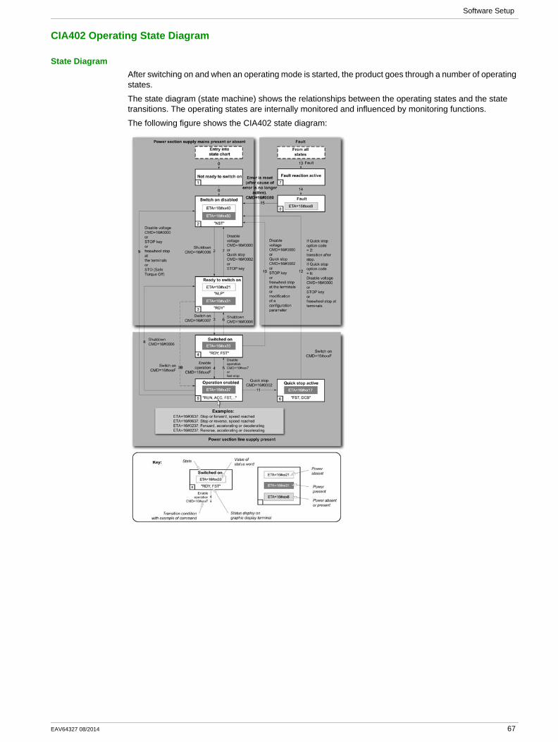
State DiagramAfter switching on and when an operating mode is started, the product goes through a number of operating states.
The state diagram (state machine) shows the relationships between the operating states and the state transitions. The operating states are internally monitored and influenced by monitoring functions.
The following figure shows the CIA402 state diagram:
EAV64327 08/2014 67
Software Setup
Description of Operating States
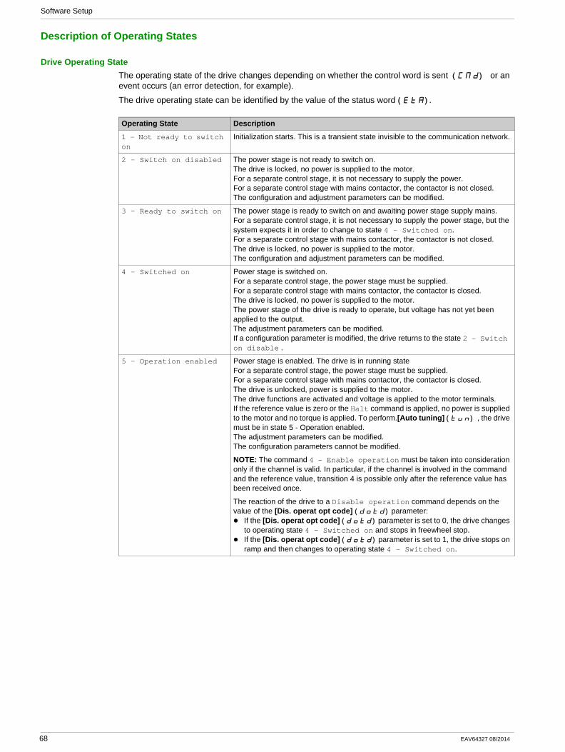
Drive Operating StateThe operating state of the drive changes depending on whether the control word is sent ( ) CMd or an event occurs (an error detection, for example).
The drive operating state can be identified by the value of the status word ( )EtA .
Operating State Description
1 - Not ready to switch on
Initialization starts. This is a transient state invisible to the communication network.
2 - Switch on disabled The power stage is not ready to switch on.The drive is locked, no power is supplied to the motor.For a separate control stage, it is not necessary to supply the power.For a separate control stage with mains contactor, the contactor is not closed.The configuration and adjustment parameters can be modified.
3 - Ready to switch on The power stage is ready to switch on and awaiting power stage supply mains.For a separate control stage, it is not necessary to supply the power stage, but the system expects it in order to change to state 4 - Switched on.For a separate control stage with mains contactor, the contactor is not closed.The drive is locked, no power is supplied to the motor.The configuration and adjustment parameters can be modified.
4 - Switched on Power stage is switched on.For a separate control stage, the power stage must be supplied.For a separate control stage with mains contactor, the contactor is closed.The drive is locked, no power is supplied to the motor.The power stage of the drive is ready to operate, but voltage has not yet been applied to the output.The adjustment parameters can be modified.If a configuration parameter is modified, the drive returns to the state 2 - Switch on disable .
5 - Operation enabled Power stage is enabled. The drive is in running stateFor a separate control stage, the power stage must be supplied.For a separate control stage with mains contactor, the contactor is closed.The drive is unlocked, power is supplied to the motor.The drive functions are activated and voltage is applied to the motor terminals.If the reference value is zero or the Halt command is applied, no power is supplied to the motor and no torque is applied. To perform.[Auto tuning] ( ) tUn , the drive must be in state 5 - Operation enabled. The adjustment parameters can be modified.The configuration parameters cannot be modified.
NOTE: The command 4 - Enable operation must be taken into consideration only if the channel is valid. In particular, if the channel is involved in the command and the reference value, transition 4 is possible only after the reference value has been received once.
The reaction of the drive to a Disable operation command depends on the value of the [Dis. operat opt code] ( )dOtd parameter:
If the [Dis. operat opt code] ( )dOtd parameter is set to 0, the drive changes to operating state 4 - Switched on and stops in freewheel stop.If the [Dis. operat opt code] ( )dOtd parameter is set to 1, the drive stops on ramp and then changes to operating state 4 - Switched on.
68 EAV64327 08/2014
Software Setup
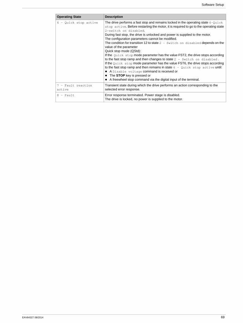
6 - Quick stop active The drive performs a fast stop and remains locked in the operating state 6-Quick stop active. Before restarting the motor, it is required to go to the operating state 2-switch on disabled.During fast stop, the drive is unlocked and power is supplied to the motor.The configuration parameters cannot be modified.The condition for transition 12 to state 2 - Switch on disabled depends on the value of the parameterQuick stop mode (QStd):If the Quick stop mode parameter has the value FST2, the drive stops according to the fast stop ramp and then changes to state 2 - Switch on disabled .If the Quick stop mode parameter has the value FST6, the drive stops according to the fast stop ramp and then remains in state 6 - Quick stop active until:
A Disable voltage command is received orThe STOP key is pressed orA freewheel stop command via the digital input of the terminal.
7 - Fault reaction active
Transient state during which the drive performs an action corresponding to the selected error response.
8 - Fault Error response terminated. Power stage is disabled.The drive is locked, no power is supplied to the motor.
Operating State Description
EAV64327 08/2014 69
Software Setup
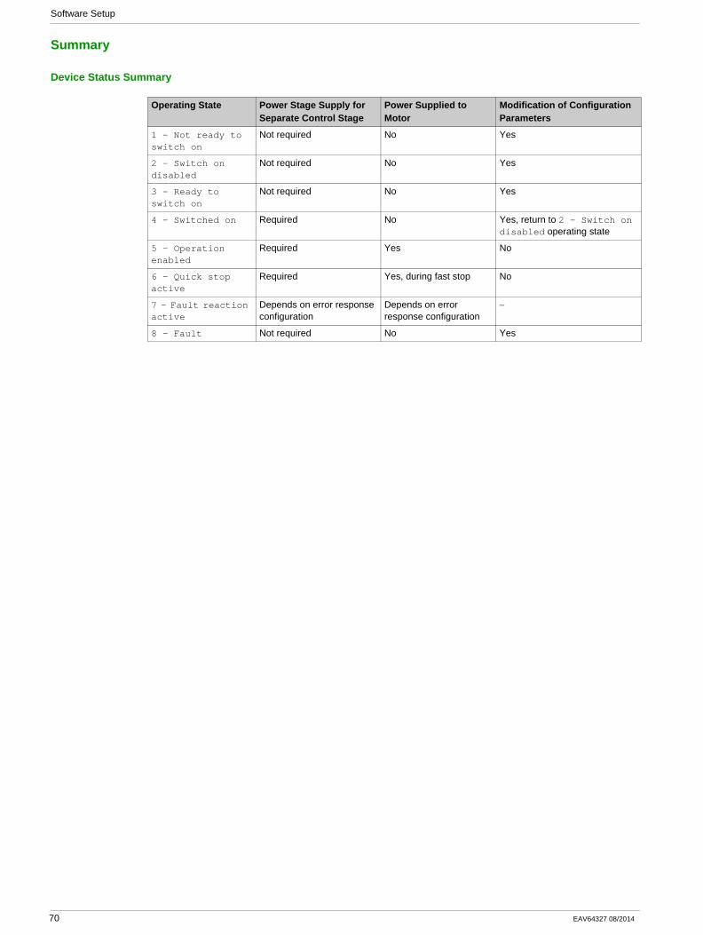
Summary
Device Status Summary
Operating State Power Stage Supply for Separate Control Stage
Power Supplied to Motor
Modification of Configuration Parameters
1 - Not ready to switch on
Not required No Yes
2 - Switch on disabled
Not required No Yes
3 - Ready to switch on
Not required No Yes
4 - Switched on Required No Yes, return to 2 - Switch on disabled operating state
5 - Operation enabled
Required Yes No
6 - Quick stop active
Required Yes, during fast stop No
7 - Fault reaction active
Depends on error response configuration
Depends on error response configuration
−
8 - Fault Not required No Yes
70 EAV64327 08/2014
Software Setup
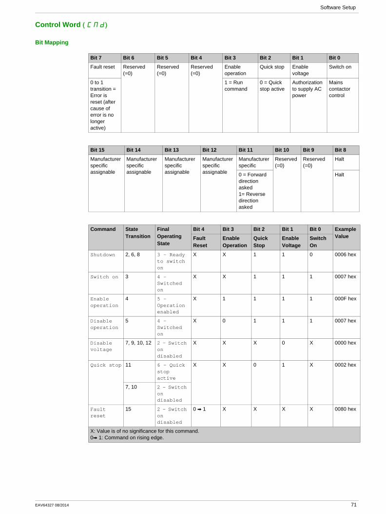
Control Word ( )CMd
Bit Mapping
Bit 7 Bit 6 Bit 5 Bit 4 Bit 3 Bit 2 Bit 1 Bit 0
Fault reset Reserved (=0)
Reserved (=0)
Reserved (=0)
Enable operation
Quick stop Enable voltage
Switch on
0 to 1 transition = Error is reset (after cause of error is no longer active)
1 = Run command
0 = Quick stop active
Authorization to supply AC power
Mains contactor control
Bit 15 Bit 14 Bit 13 Bit 12 Bit 11 Bit 10 Bit 9 Bit 8
Manufacturer specific assignable
Manufacturer specific assignable
Manufacturer specific assignable
Manufacturer specific assignable
Manufacturer specific
Reserved (=0)
Reserved (=0)
Halt
0 = Forward direction asked 1= Reverse direction asked
Halt
Command State Transition
Final Operating State
Bit 4 Bit 3 Bit 2 Bit 1 Bit 0 Example ValueFault
ResetEnable Operation
Quick Stop
Enable Voltage
Switch On
Shutdown 2, 6, 8 3 - Ready to switch on
X X 1 1 0 0006 hex
Switch on 3 4 - Switched on
X X 1 1 1 0007 hex
Enable operation
4 5 - Operation enabled
X 1 1 1 1 000F hex
Disable operation
5 4 - Switched on
X 0 1 1 1 0007 hex
Disable voltage
7, 9, 10, 12 2 - Switch on disabled
X X X 0 X 0000 hex
Quick stop 11 6 - Quick stop active
X X 0 1 X 0002 hex
7, 10 2 - Switch on disabled
Fault reset
15 2 - Switch on disabled
0 V 1 X X X X 0080 hex
X: Value is of no significance for this command.0V 1: Command on rising edge.
EAV64327 08/2014 71
Software Setup
Stop Commands
Halt CommandThe Halt command enables movement to be interrupted without having to leave the 5 - Operation enabled state. The stop is performed in accordance with the [Type of stop] ( )Stt parameter.
If the Halt command is active, no power is supplied to the motor and no torque is applied.
Regardless of the assignment of the [Type of stop] ( )Stt parameter [Fast stop assign] ( )FSt ,[Ramp stop] ( )rMP , [Freewheel] ( )nSt , or [DC injection assign.] ( )dCI ), the drive remains in the 5 - Operation enabled state.
Fast Stop CommandA Fast Stop command at the terminals or using a bit of the control word assigned to Fast Stop causes a change to the 4 - Switched on
Freewheel CommandA Freewheel Stop command using a digital input of the terminal or a bit of the control word assigned to Freewheel Stop causes a change to operating state 2 - Switch on disabled.
72 EAV64327 08/2014
Software Setup
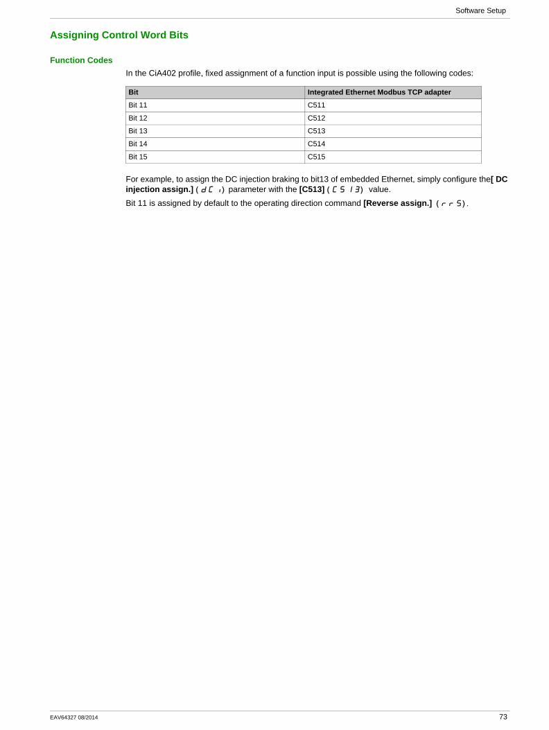
Assigning Control Word Bits
Function CodesIn the CiA402 profile, fixed assignment of a function input is possible using the following codes:
For example, to assign the DC injection braking to bit13 of embedded Ethernet, simply configure the[ DC injection assign.] ( )dCI parameter with the [C513] ( ) C513 value.
Bit 11 is assigned by default to the operating direction command [Reverse assign.] ( )rrS .
Bit Integrated Ethernet Modbus TCP adapter
Bit 11 C511
Bit 12 C512
Bit 13 C513
Bit 14 C514
Bit 15 C515
EAV64327 08/2014 73
Software Setup
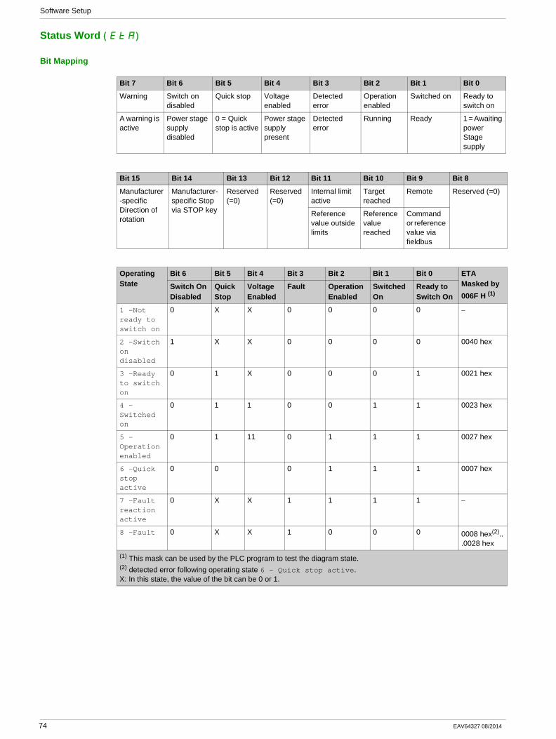
Status Word ( )EtA
Bit Mapping
Bit 7 Bit 6 Bit 5 Bit 4 Bit 3 Bit 2 Bit 1 Bit 0
Warning Switch on disabled
Quick stop Voltage enabled
Detected error
Operation enabled
Switched on Ready to switch on
A warning is active
Power stage supply disabled
0 = Quick stop is active
Power stage supply present
Detected error
Running Ready 1 = Awaiting power Stage supply
Bit 15 Bit 14 Bit 13 Bit 12 Bit 11 Bit 10 Bit 9 Bit 8
Manufacturer-specific Direction of rotation
Manufacturer-specific Stop via STOP key
Reserved (=0)
Reserved (=0)
Internal limit active
Target reached
Remote Reserved (=0)
Reference value outside limits
Reference value reached
Command or reference value via fieldbus
Operating State
Bit 6 Bit 5 Bit 4 Bit 3 Bit 2 Bit 1 Bit 0 ETA Masked by 006F H (1)
Switch On Disabled
Quick Stop
Voltage Enabled
Fault Operation Enabled
Switched On
Ready to Switch On
1 -Not ready to switch on
0 X X 0 0 0 0 −
2 -Switch on disabled
1 X X 0 0 0 0 0040 hex
3 -Ready to switch on
0 1 X 0 0 0 1 0021 hex
4 -Switched on
0 1 1 0 0 1 1 0023 hex
5 -Operation enabled
0 1 11 0 1 1 1 0027 hex
6 -Quick stop active
0 0 0 1 1 1 0007 hex
7 -Fault reaction active
0 X X 1 1 1 1 −
8 -Fault 0 X X 1 0 0 0 0008 hex(2)...0028 hex
(1) This mask can be used by the PLC program to test the diagram state.(2) detected error following operating state 6 - Quick stop active.X: In this state, the value of the bit can be 0 or 1.
74 EAV64327 08/2014
Software Setup
Starting Sequence
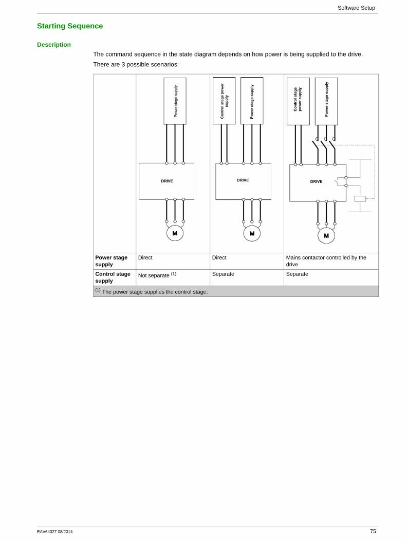
DescriptionThe command sequence in the state diagram depends on how power is being supplied to the drive.
There are 3 possible scenarios:
Power stage supply
Direct Direct Mains contactor controlled by the drive
Control stage supply
Not separate (1) Separate Separate
(1) The power stage supplies the control stage.
EAV64327 08/2014 75
Software Setup
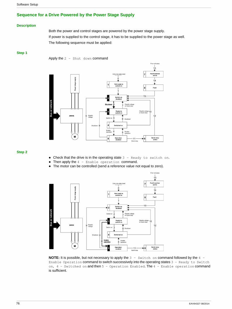
Sequence for a Drive Powered by the Power Stage Supply
DescriptionBoth the power and control stages are powered by the power stage supply.
If power is supplied to the control stage, it has to be supplied to the power stage as well.
The following sequence must be applied:
Step 1Apply the 2 - Shut down command
Step 2Check that the drive is in the operating state 3 - Ready to switch on.Then apply the 4 - Enable operation command.The motor can be controlled (send a reference value not equal to zero).
NOTE: It is possible, but not necessary to apply the 3 - Switch on command followed by the 4 - Enable Operation command to switch successively into the operating states 3 - Ready to Switch on, 4 - Switched on and then 5 - Operation Enabled. The 4 - Enable operation command is sufficient.
76 EAV64327 08/2014
Software Setup
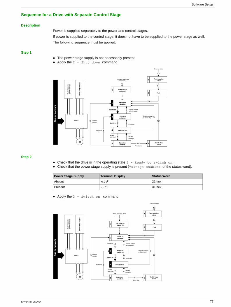
Sequence for a Drive with Separate Control Stage
DescriptionPower is supplied separately to the power and control stages.
If power is supplied to the control stage, it does not have to be supplied to the power stage as well.
The following sequence must be applied:
Step 1The power stage supply is not necessarily present.Apply the 2 - Shut down command
Step 2Check that the drive is in the operating state 3 - Ready to switch on.Check that the power stage supply is present (Voltage enabled of the status word).
Apply the 3 - Switch on command
Power Stage Supply Terminal Display Status Word
Absent nLP 21 hex
Present rdY 31 hex
EAV64327 08/2014 77
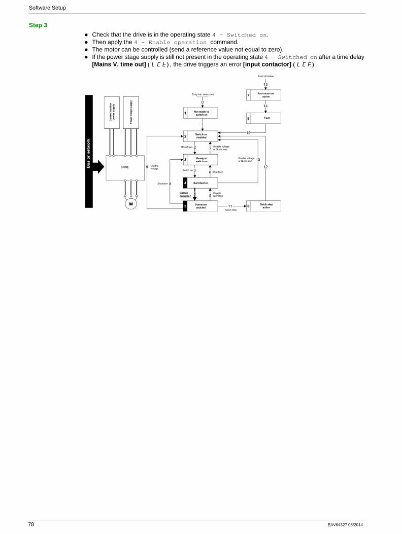
Software Setup
Step 3Check that the drive is in the operating state 4 - Switched on.Then apply the 4 - Enable operation command.The motor can be controlled (send a reference value not equal to zero).If the power stage supply is still not present in the operating state 4 - Switched on after a time delay [Mains V. time out] ( )LCt , the drive triggers an error [input contactor] ( )LCF .
78 EAV64327 08/2014
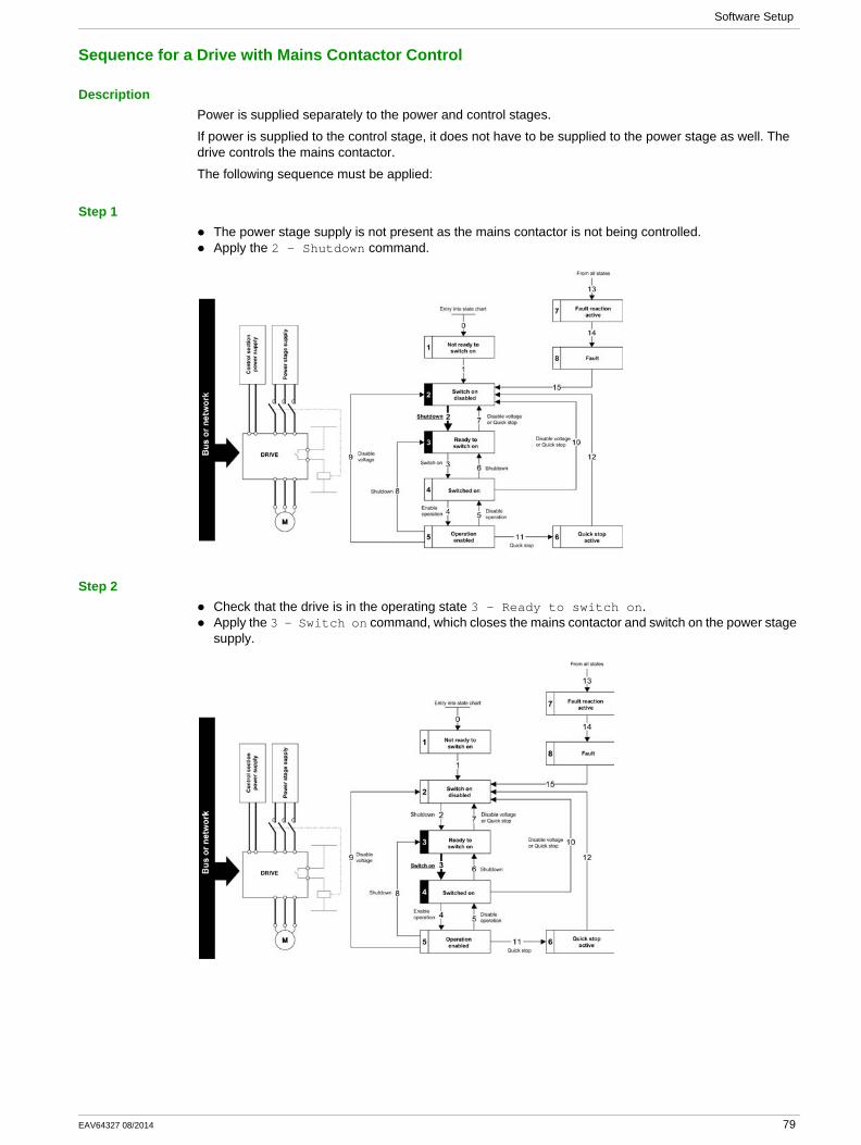
Software Setup
Sequence for a Drive with Mains Contactor Control
DescriptionPower is supplied separately to the power and control stages.
If power is supplied to the control stage, it does not have to be supplied to the power stage as well. The drive controls the mains contactor.
The following sequence must be applied:
Step 1The power stage supply is not present as the mains contactor is not being controlled.Apply the 2 - Shutdown command.
Step 2Check that the drive is in the operating state 3 - Ready to switch on.Apply the 3 - Switch on command, which closes the mains contactor and switch on the power stage supply.
EAV64327 08/2014 79
Software Setup
Embedded Webserver
Section 4.5Embedded Webserver
What Is in This Section?This section contains the following topics:
Topic Page
Overview 81
Connection to the Webserver 82
80 EAV64327 08/2014

Software Setup
Overview
WebserverThe Ethernet adapter provides an integrated Web server which allows several functions like: display, parameter settings, and diagnostics. This chapter describes the services provided by this webserver.
The webserver can be accessed from standard browsers like Internet Explorer, chrome, safari, or Firefox.
EAV64327 08/2014 81
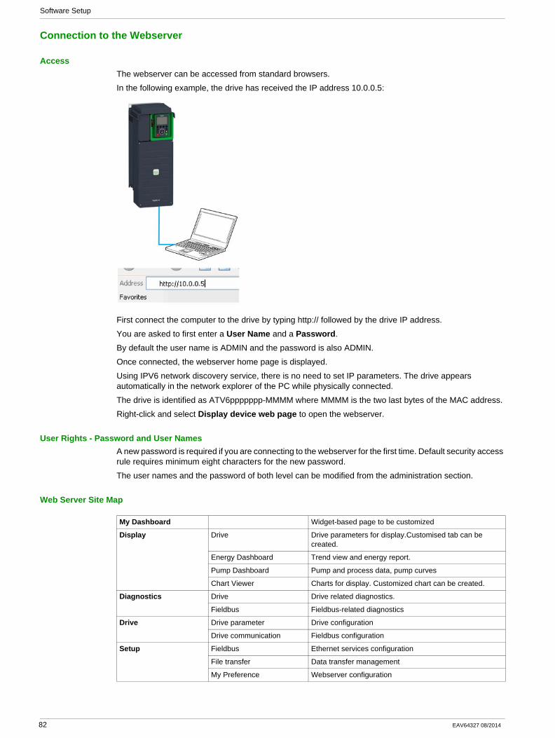
Software Setup
Connection to the Webserver
AccessThe webserver can be accessed from standard browsers.
In the following example, the drive has received the IP address 10.0.0.5:
First connect the computer to the drive by typing http:// followed by the drive IP address.
You are asked to first enter a User Name and a Password.
By default the user name is ADMIN and the password is also ADMIN.
Once connected, the webserver home page is displayed.
Using IPV6 network discovery service, there is no need to set IP parameters. The drive appears automatically in the network explorer of the PC while physically connected.
The drive is identified as ATV6ppppppp-MMMM where MMMM is the two last bytes of the MAC address.
Right-click and select Display device web page to open the webserver.
User Rights - Password and User NamesA new password is required if you are connecting to the webserver for the first time. Default security access rule requires minimum eight characters for the new password.
The user names and the password of both level can be modified from the administration section.
Web Server Site Map
My Dashboard Widget-based page to be customized
Display Drive Drive parameters for display.Customised tab can be created.
Energy Dashboard Trend view and energy report.
Pump Dashboard Pump and process data, pump curves
Chart Viewer Charts for display. Customized chart can be created.
Diagnostics Drive Drive related diagnostics.
Fieldbus Fieldbus-related diagnostics
Drive Drive parameter Drive configuration
Drive communication Fieldbus configuration
Setup Fieldbus Ethernet services configuration
File transfer Data transfer management
My Preference Webserver configuration
82 EAV64327 08/2014

Operations
Chapter 5Operations
What Is in This Chapter?This chapter contains the following sections:
Section Topic Page
5.1 Operating States 84
5.2 Operating Modes 86
EAV64327 08/2014 83
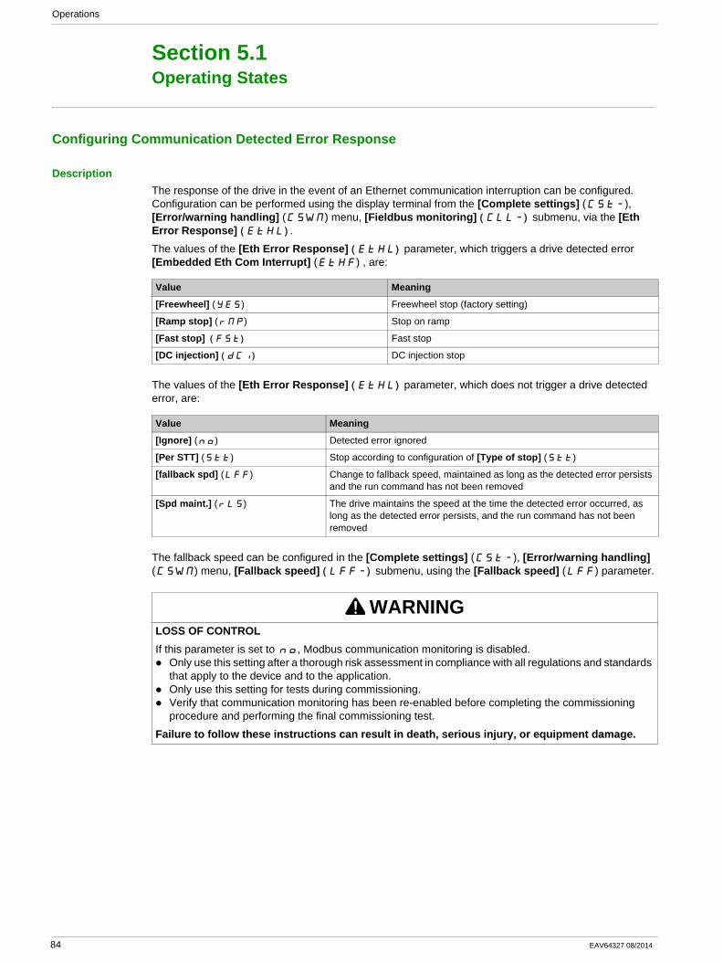
Operations
Operating States
Section 5.1Operating States
Configuring Communication Detected Error Response
DescriptionThe response of the drive in the event of an Ethernet communication interruption can be configured. Configuration can be performed using the display terminal from the [Complete settings] (CSt-), [Error/warning handling] (CSWM) menu, [Fieldbus monitoring] ( )CLL- submenu, via the [Eth Error Response] ( )EtHL .
The values of the [Eth Error Response] ( )EtHL parameter, which triggers a drive detected error [Embedded Eth Com Interrupt] (EtHF) , are:
The values of the [Eth Error Response] ( )EtHL parameter, which does not trigger a drive detected error, are:
The fallback speed can be configured in the [Complete settings] (CSt-), [Error/warning handling] (CSWM) menu, [Fallback speed] ( )LFF- submenu, using the [Fallback speed] (LFF) parameter.
Value Meaning
[Freewheel] (YES) Freewheel stop (factory setting)
[Ramp stop] (rMP) Stop on ramp
[Fast stop] ( )FSt Fast stop
[DC injection] ( )dCI DC injection stop
Value Meaning
[Ignore] (nO) Detected error ignored
[Per STT] (Stt) Stop according to configuration of [Type of stop] (Stt)
[fallback spd] (LFF) Change to fallback speed, maintained as long as the detected error persists and the run command has not been removed
[Spd maint.] (rLS) The drive maintains the speed at the time the detected error occurred, as long as the detected error persists, and the run command has not been removed
WARNINGLOSS OF CONTROLIf this parameter is set to nO, Modbus communication monitoring is disabled.
Only use this setting after a thorough risk assessment in compliance with all regulations and standards that apply to the device and to the application.Only use this setting for tests during commissioning.Verify that communication monitoring has been re-enabled before completing the commissioning procedure and performing the final commissioning test.
Failure to follow these instructions can result in death, serious injury, or equipment damage.
84 EAV64327 08/2014
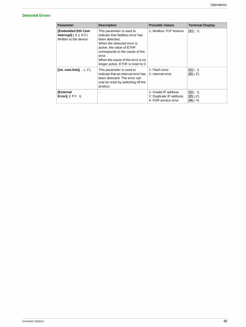
Operations
Detected Errors
Parameter Description Possible Values Terminal Display
[Embedded Eth Com Interrupt] ( )EtHF
Written to the device
This parameter is used to indicate that fieldbus error has been detected.When the detected error is active, the value of ETHF corresponds to the cause of the error.When the cause of the error is no longer active, ETHF is reset to 0.
1: Modbus TCP timeout [1] ( )1
[int. com.link]( )ILF This parameter is used to indicate that an internal error has been detected. The error can only be reset by switching off the product.
1: Flash error2: Internal error
[1] ( )1
[2] ( )2
[External Error]( )EPF1
− 1: Invalid IP address2: Duplicate IP address4: FDR service error
[1] ( )1
[2] ( )2
[4] ( )4
EAV64327 08/2014 85
Operations
Operating Modes
Section 5.2Operating Modes
What Is in This Section?This section contains the following topics:
Topic Page
Configuring the Control Channel 87
Configuration of the Drive for Operation in I/O Profile 88
Configuration of the Drive for Operation with CiA 402 Profile in Combined Mode 89
Configuration of the Drive for Operation with CiA 402 Profile in Separate Mode 90
86 EAV64327 08/2014
Operations
Configuring the Control Channel
OverviewThis chapter explains how to configure the drive for operation from communication network through three following examples.
I/O mode - a simple command word (based on forward, reverse, and reset binary commands).Combined mode (with native profile CiA 402) - Both reference value and command word come from the communication network.Separate (with native profile CiA 402) - reference value and command come from separate sources: for example, the command (in CiA 402) comes from the communication network and the reference value from the HMI.
EAV64327 08/2014 87
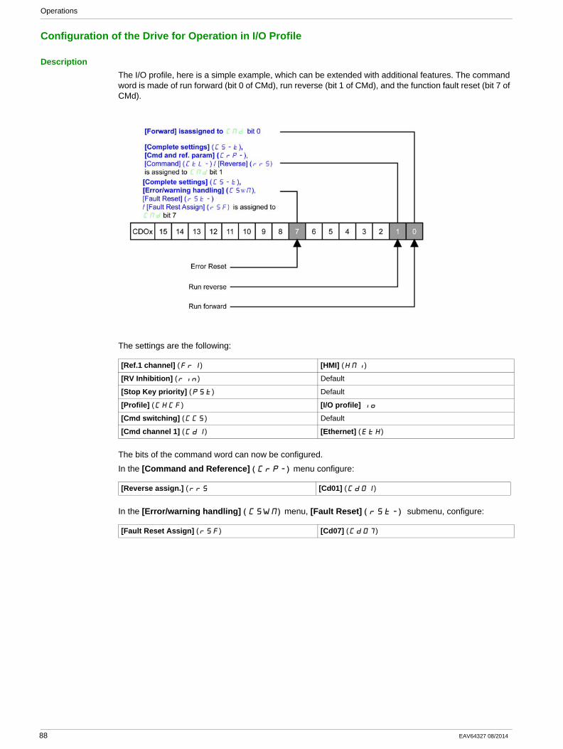
Operations
Configuration of the Drive for Operation in I/O Profile
DescriptionThe I/O profile, here is a simple example, which can be extended with additional features. The command word is made of run forward (bit 0 of CMd), run reverse (bit 1 of CMd), and the function fault reset (bit 7 of CMd).
The settings are the following:
The bits of the command word can now be configured.
In the [Command and Reference] ( )CrP- menu configure:
In the [Error/warning handling] ( )CSWM menu, [Fault Reset] ( ) rSt- submenu, configure:
[Ref.1 channel] (Fr1) [HMI] (HMI)
[RV Inhibition] (rIn) Default
[Stop Key priority] (PSt) Default
[Profile] (CHCF) [I/O profile] IO
[Cmd switching] (CCS) Default
[Cmd channel 1] (Cd1) [Ethernet] (EtH)
[Reverse assign.] (rrS [Cd01] (Cd01)
[Fault Reset Assign] (rSF) [Cd07] (Cd07)
88 EAV64327 08/2014
Operations
Configuration of the Drive for Operation with CiA 402 Profile in Combined Mode
DescriptionThis section describes how to configure the settings of the drive if it is controlled in CiA 402 mode. The example focuses on the not separate mode. Additional modes are detailed in the drive programming manual.
In the [Complete settings] ( ) CSt- menu, [Command and reference] ( )CrP- submenu:):[Ref.1 Channel] (Fr1): is set on according to the communication source you can choose in the following table:
[Profile] (CHCF): defines if the drive operates in combined mode (reference value and command from the same channel).
Origin of the Control Ref1 Channel Setting
Modbus TCP [Ethernet] (EtH)
EAV64327 08/2014 89
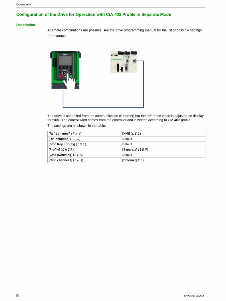
Operations
Configuration of the Drive for Operation with CiA 402 Profile in Separate Mode
DescriptionAlternate combinations are possible, see the drive programming manual for the list of possible settings.
For example:
The drive is controlled from the communication (Ethernet) but the reference value is adjusted on display terminal. The control word comes from the controller and is written according to CiA 402 profile.
The settings are as shown in the table:
[Ref.1 channel] (Fr1) [HMI] (LCC)
[RV Inhibition] (rIn) Default
[Stop Key priority] (PSt) Default
[Profile] (CHCF) [Separate] (SEp)
[Cmd switching] (CCS) Default
[Cmd channel 1] (Cd1) [Ethernet] EtH
90 EAV64327 08/2014

Diagnostic and Troubleshooting
Chapter 6Diagnostic and Troubleshooting
What Is in This Chapter?This chapter contains the following topics:
Topic Page
Fieldbus Status LEDs 92
Connection for Fieldbus Mode 94
Fieldbus Functions Test 95
EAV64327 08/2014 91
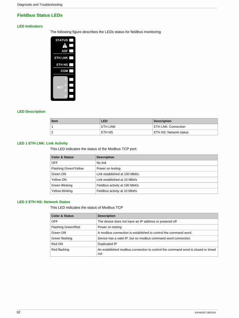
Diagnostic and Troubleshooting
Fieldbus Status LEDs
LED IndicatorsThe following figure describes the LEDs status for fieldbus monitoring
LED Description
LED 1 ETH LNK: Link ActivityThis LED indicates the status of the Modbus TCP port:
LED 2 ETH NS: Network StatusThis LED indicates the status of Modbus TCP
Item LED Description
1 ETH LINK ETH LNK: Connection
2 ETH NS ETH NS: Network status
Color & Status Description
OFF No link
Flashing Green/Yellow Power on testing
Green ON Link established at 100 Mbit/s
Yellow ON Link established at 10 Mbit/s
Green Blinking Fieldbus activity at 100 Mbit/s
Yellow blinking Fieldbus activity at 10 Mbit/s
Color & Status Description
OFF The device does not have an IP address or powered off
Flashing Green/Red Power on testing
Green ON A modbus connection is established to control the command word.
Green flashing Device has a valid IP, but no modbus command word connection.
Red ON Duplicated IP
Red flashing An established modbus connection to control the command word is closed or timed out
92 EAV64327 08/2014
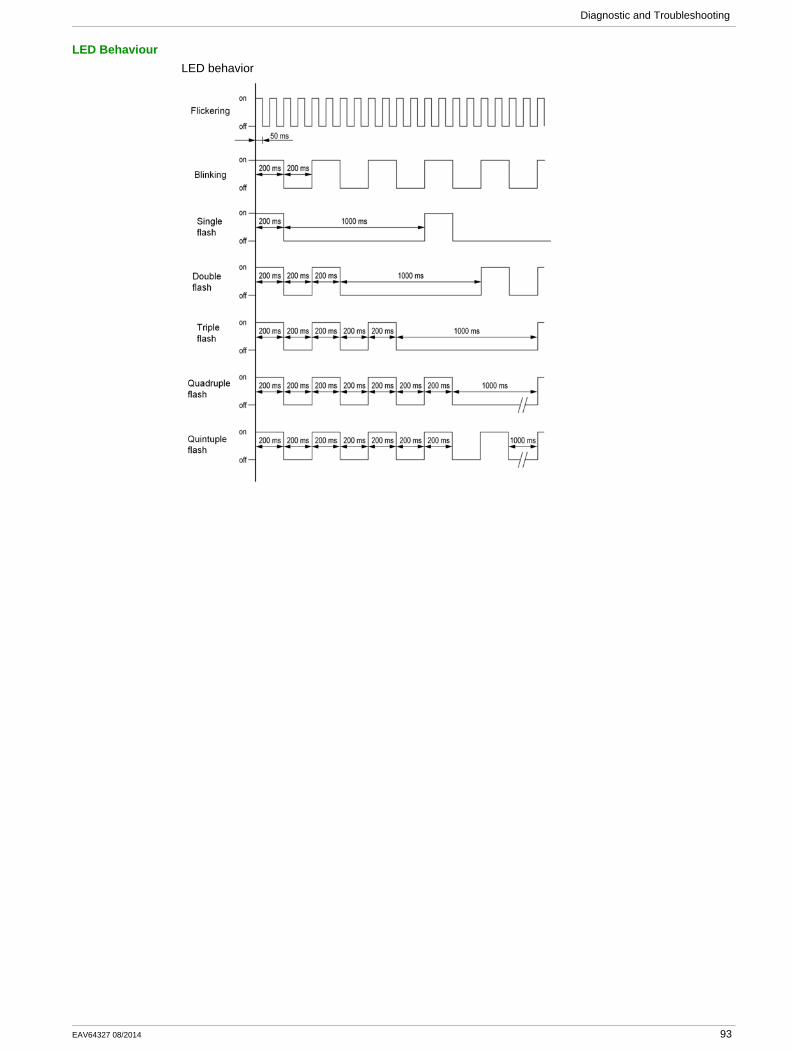
Diagnostic and Troubleshooting
LED BehaviourLED behavior
EAV64327 08/2014 93

Diagnostic and Troubleshooting
Connection for Fieldbus Mode
DescriptionIf the product cannot be addressed via the fieldbus, first check the connections. The product manuals contains the technical data of the device and information on fieldbus and device installation.
Verify the following:Power connections to the deviceFieldbus cable and fieldbus wiringFieldbus connection to the device
94 EAV64327 08/2014
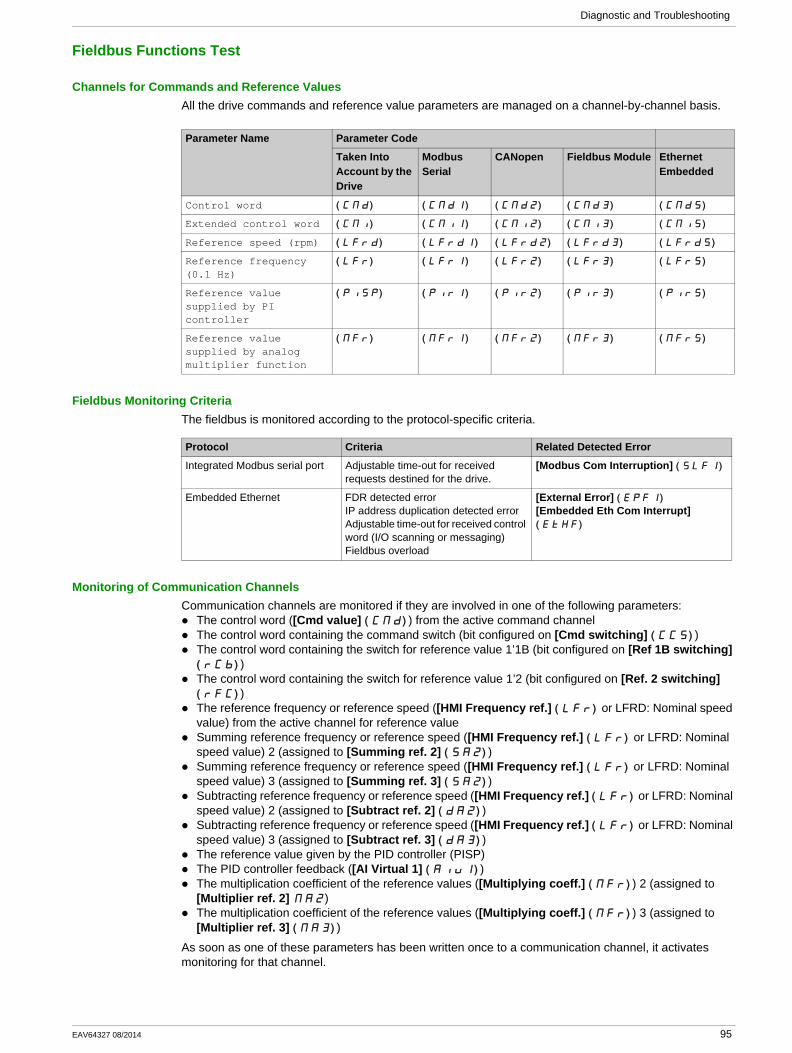
Diagnostic and Troubleshooting
Fieldbus Functions Test
Channels for Commands and Reference ValuesAll the drive commands and reference value parameters are managed on a channel-by-channel basis.
Fieldbus Monitoring CriteriaThe fieldbus is monitored according to the protocol-specific criteria.
Monitoring of Communication ChannelsCommunication channels are monitored if they are involved in one of the following parameters:
The control word ([Cmd value] ( )CMd ) from the active command channelThe control word containing the command switch (bit configured on [Cmd switching] ( )CCS )The control word containing the switch for reference value 1’1B (bit configured on [Ref 1B switching] ( )rCb )The control word containing the switch for reference value 1’2 (bit configured on [Ref. 2 switching] ( )rFC )The reference frequency or reference speed ([HMI Frequency ref.] ( )LFr or LFRD: Nominal speed value) from the active channel for reference valueSumming reference frequency or reference speed ([HMI Frequency ref.] ( )LFr or LFRD: Nominal speed value) 2 (assigned to [Summing ref. 2] ( )SA2 )Summing reference frequency or reference speed ([HMI Frequency ref.] ( )LFr or LFRD: Nominal speed value) 3 (assigned to [Summing ref. 3] ( )SA2 )Subtracting reference frequency or reference speed ([HMI Frequency ref.] ( )LFr or LFRD: Nominal speed value) 2 (assigned to [Subtract ref. 2] ( )dA2 )Subtracting reference frequency or reference speed ([HMI Frequency ref.] ( )LFr or LFRD: Nominal speed value) 3 (assigned to [Subtract ref. 3] ( )dA3 )The reference value given by the PID controller (PISP)The PID controller feedback ([AI Virtual 1] ( )AIU1 )The multiplication coefficient of the reference values ([Multiplying coeff.] ( )MFr ) 2 (assigned to [Multiplier ref. 2] MA2)The multiplication coefficient of the reference values ([Multiplying coeff.] ( )MFr ) 3 (assigned to [Multiplier ref. 3] ( )MA3 )
As soon as one of these parameters has been written once to a communication channel, it activates monitoring for that channel.
Parameter Name Parameter Code
Taken Into Account by the Drive
Modbus Serial
CANopen Fieldbus Module Ethernet Embedded
Control word ( )CMd ( )CMd1 ( )CMd2 ( )CMd3 ( )CMd5
Extended control word ( )CMI ( )CMI1 ( )CMI2 ( )CMI3 ( )CMI5
Reference speed (rpm) ( )LFrd ( )LFrd1 ( )LFrd2 ( )LFrd3 ( )LFrd5
Reference frequency (0.1 Hz)
( )LFr ( )LFr1 ( )LFr2 ( )LFr3 ( )LFr5
Reference value supplied by PI controller
( )PISP ( )PIr1 ( )PIr2 ( )PIr3 ( )PIr5
Reference value supplied by analog multiplier function
( )MFr ( )MFr1 ( )MFr2 ( )MFr3 ( )MFr5
Protocol Criteria Related Detected Error
Integrated Modbus serial port Adjustable time-out for received requests destined for the drive.
[Modbus Com Interruption] ( )SLF1
Embedded Ethernet FDR detected errorIP address duplication detected errorAdjustable time-out for received control word (I/O scanning or messaging)Fieldbus overload
[External Error] ( )EPF1
[Embedded Eth Com Interrupt] ( )EtHF
EAV64327 08/2014 95
Diagnostic and Troubleshooting
If a communication warning is sent (in accordance with the protocol criteria) by a monitored port or fieldbus module, the drive triggers a communication interruption.
The drive reacts according to the communication interruption configuration (operating state Fault, maintenance, fallback, and so on)
If a communication warning occurs on a channel that is not being monitored, the drive does not trigger a communication interruption.
Enabling of Communication ChannelsA communication channel is enabled once all the parameters involved have been written at least one time.The drive is only able to start if all channels involved in command and reference value are enabled.
For example:
A drive in DSP402 profile is connected to an active communication channel.
It is mandatory to write at least 1 time the reference value and the command in order to switch from 4-Switched on to operating state 5-Operation enabled.
A communication channel is disabled:In the event of a communication warning.In forced local mode.
NOTE: On exiting forced local mode:
The drive copies the run commands, the direction, and the forced local reference to the active channel (maintained).Monitoring of the active channel for commands and/or reference value resumes following a time delay [Time-out forc. local] ( )FLOt .Drive control only takes effect once the drive has received the reference value and the command from the active channel.
96 EAV64327 08/2014
Glossary
AAbbreviations
Req. = Required
Opt. = Optional
DDisplay terminal
The display terminal menus are shown in square brackets.
For example: [Communication]The codes are shown in round brackets.
For example: (CON-)
Parameter names are displayed on the display terminal in square brackets.
For example: [fallback spd]Parameter codes are displayed in round brackets.
For example: (LFF)
EError
Discrepancy between a detected (computed, measured, or signaled) value or condition and the specified or theoretically correct value or condition.
FFactory setting
Factory settings when the product is shipped
FaultFault is an operating state. If the monitoring functions detect an error, a transition to this operating state is triggered, depending on the error class. A "Fault reset" is required to exit this operating state after the cause of the detected error has been removed. Further information can be found in the pertinent standards such as IEC 61800-7, ODVA Common Industrial Protocol (CIP).
Fault ResetA function used to restore the drive to an operational state after a detected error is cleared by removing the cause of the error so that the error is no longer active.
MMonitoring function
Monitoring functions acquire a value continuously or cyclically (for example, by measuring) in order to check whether it is within permissible limits. Monitoring functions are used for error detection.
PParameter
Device data and values that can be read and set (to a certain extent) by the user.
PELVProtective Extra Low Voltage, low voltage with isolation. For more information: IEC 60364-4-41
PLCProgrammable logic controller
EAV64327 08/2014 97

Glossary
Power stageThe power stage controls the motor. The power stage generates current for controlling the motor.
QQuick Stop
The Quick Stop function can be used for fast deceleration of a movement as a response to a detected error or via a command.
WWarning
If the term is used outside the context of safety instructions, a warning alerts to a potential problem that was detected by a monitoring function. A warning does not cause a transition of the operating state.
98 EAV64327 08/2014


Altivar_Ethernet Manual(Embedded)_EN_EAV64327_01 08/2014