Embed Size (px)
Citation preview
Junos®OS
Ethernet Interfaces Configuration Guide
Release
11.4
Published: 2011-11-14
Copyright © 2011, Juniper Networks, Inc.

Juniper Networks, Inc.1194 North Mathilda AvenueSunnyvale, California 94089USA408-745-2000www.juniper.net
This product includes the Envoy SNMP Engine, developed by Epilogue Technology, an Integrated Systems Company. Copyright © 1986-1997,Epilogue Technology Corporation. All rights reserved. This program and its documentation were developed at private expense, and no partof them is in the public domain.
This product includes memory allocation software developed by Mark Moraes, copyright © 1988, 1989, 1993, University of Toronto.
This product includes FreeBSD software developed by the University of California, Berkeley, and its contributors. All of the documentationand software included in the 4.4BSD and 4.4BSD-Lite Releases is copyrighted by the Regents of the University of California. Copyright ©1979, 1980, 1983, 1986, 1988, 1989, 1991, 1992, 1993, 1994. The Regents of the University of California. All rights reserved.
GateD software copyright © 1995, the Regents of the University. All rights reserved. Gate Daemon was originated and developed throughrelease 3.0 by Cornell University and its collaborators. Gated is based on Kirton’s EGP, UC Berkeley’s routing daemon (routed), and DCN’sHELLO routing protocol. Development of Gated has been supported in part by the National Science Foundation. Portions of the GateDsoftware copyright © 1988, Regents of the University of California. All rights reserved. Portions of the GateD software copyright © 1991, D.L. S. Associates.
This product includes software developed by Maker Communications, Inc., copyright © 1996, 1997, Maker Communications, Inc.
Juniper Networks, Junos, Steel-Belted Radius, NetScreen, and ScreenOS are registered trademarks of Juniper Networks, Inc. in the UnitedStates and other countries. The Juniper Networks Logo, the Junos logo, and JunosE are trademarks of Juniper Networks, Inc. All othertrademarks, service marks, registered trademarks, or registered service marks are the property of their respective owners.
Juniper Networks assumes no responsibility for any inaccuracies in this document. Juniper Networks reserves the right to change, modify,transfer, or otherwise revise this publication without notice.
Products made or sold by Juniper Networks or components thereof might be covered by one or more of the following patents that areowned by or licensed to Juniper Networks: U.S. Patent Nos. 5,473,599, 5,905,725, 5,909,440, 6,192,051, 6,333,650, 6,359,479, 6,406,312,6,429,706, 6,459,579, 6,493,347, 6,538,518, 6,538,899, 6,552,918, 6,567,902, 6,578,186, and 6,590,785.
Junos®OS Ethernet Interfaces Configuration Guide
Release 11.4Copyright © 2011, Juniper Networks, Inc.All rights reserved.
Revision HistoryNovember 2011—R1 Junos® OS 11.4
The information in this document is current as of the date listed in the revision history.
YEAR 2000 NOTICE
Juniper Networks hardware and software products are Year 2000 compliant. Junos OS has no known time-related limitations through theyear 2038. However, the NTP application is known to have some difficulty in the year 2036.
ENDUSER LICENSE AGREEMENT
The Juniper Networks product that is the subject of this technical documentation consists of (or is intended for use with) Juniper Networkssoftware. Use of such software is subject to the terms and conditions of the End User License Agreement (“EULA”) posted at
http://www.juniper.net/support/eula.html. By downloading, installing or using such software, you agree to the terms and conditionsof that EULA.
Copyright © 2011, Juniper Networks, Inc.ii
Abbreviated Table of Contents
About This Guide . . . . . . . . . . . . . . . . . . . . . . . . . . . . . . . . . . . . . . . . . . . . . . . . xxvii
Part 1 Ethernet Interfaces Configuration Statements Overview
Chapter 1 Ethernet Interfaces Configuration Statements and Hierarchy . . . . . . . . . . . . 3
Part 2 Configuring Ethernet Interfaces
Chapter 2 Configuring Ethernet Interfaces . . . . . . . . . . . . . . . . . . . . . . . . . . . . . . . . . . . . . 35
Chapter 3 Configuring 802.1Q VLANs . . . . . . . . . . . . . . . . . . . . . . . . . . . . . . . . . . . . . . . . . 53
Chapter 4 Configuring Aggregated Ethernet Interfaces . . . . . . . . . . . . . . . . . . . . . . . . . . 81
Chapter 5 Stacking and Rewriting Gigabit Ethernet VLAN Tags . . . . . . . . . . . . . . . . . . 125
Chapter 6 Configuring Layer 2 Bridging Interfaces . . . . . . . . . . . . . . . . . . . . . . . . . . . . . . 151
Chapter 7 Configuring Link Layer Discovery Protocol . . . . . . . . . . . . . . . . . . . . . . . . . . . 153
Chapter 8 Configuring TCC and Layer 2.5 Switching . . . . . . . . . . . . . . . . . . . . . . . . . . . . 159
Chapter 9 Configuring Static ARP Table Entries . . . . . . . . . . . . . . . . . . . . . . . . . . . . . . . 163
Chapter 10 Configuring Restricted and Unrestricted Proxy ARP . . . . . . . . . . . . . . . . . . . 165
Chapter 11 Configuring MAC Address Validation on Static Ethernet Interfaces . . . . . 169
Chapter 12 Enabling Passive Monitoring on Ethernet Interfaces . . . . . . . . . . . . . . . . . . . 173
Chapter 13 Configuring IEEE 802.1ag OAM Connectivity-Fault Management . . . . . . . 177
Chapter 14 Configuring ITU-T Y.1731 Ethernet Service OAM . . . . . . . . . . . . . . . . . . . . . . 233
Chapter 15 Configuring IEEE 802.1x Port-Based Network Access Control . . . . . . . . . . 283
Chapter 16 Configuring IEEE 802.3ah OAM Link-Fault Management . . . . . . . . . . . . . . 287
Chapter 17 Configuring VRRP and VRRP for IPv6 . . . . . . . . . . . . . . . . . . . . . . . . . . . . . . . 307
Chapter 18 Configuring Gigabit Ethernet Accounting and Policing . . . . . . . . . . . . . . . . . 311
Chapter 19 Configuring Gigabit Ethernet Autonegotiation . . . . . . . . . . . . . . . . . . . . . . . 325
Chapter 20 Configuring Gigabit Ethernet OTNOptions . . . . . . . . . . . . . . . . . . . . . . . . . . . 331
Chapter 21 Configuring the Management Ethernet Interface . . . . . . . . . . . . . . . . . . . . . 333
Chapter 22 Configuring 10-Gigabit Ethernet LAN/WAN PICs . . . . . . . . . . . . . . . . . . . . . 337
Chapter 23 Configuring the 10-Gigabit Ethernet DWDM Interface Wavelength . . . . . 345
Chapter 24 Configuring 10-Gigabit Ethernet Framing . . . . . . . . . . . . . . . . . . . . . . . . . . . . 347
Chapter 25 Configuring 10-Gigabit Ethernet Notification of Link Down Alarm . . . . . . . 351
Chapter 26 Configuring 10-Gigabit Ethernet Notification of Link Down for OpticsAlarms . . . . . . . . . . . . . . . . . . . . . . . . . . . . . . . . . . . . . . . . . . . . . . . . . . . . . . . . . . 353
Chapter 27 Configuring 100-Gigabit Ethernet PICs . . . . . . . . . . . . . . . . . . . . . . . . . . . . . 355
iiiCopyright © 2011, Juniper Networks, Inc.

Chapter 28 Configuring 40-Gigabit Ethernet PICs . . . . . . . . . . . . . . . . . . . . . . . . . . . . . . 365
Chapter 29 Configuring Point-to-Point Protocol over Ethernet . . . . . . . . . . . . . . . . . . . 369
Chapter 30 Configuring Ethernet Automatic Protection Switching . . . . . . . . . . . . . . . . 405
Chapter 31 Configuring Ethernet Ring Protection Switching . . . . . . . . . . . . . . . . . . . . . . 413
Chapter 32 Example Ethernet Configurations . . . . . . . . . . . . . . . . . . . . . . . . . . . . . . . . . . 427
Part 3 Ethernet Interface Configuration Statements
Chapter 33 Summary of Ethernet Interfaces Configuration Statements . . . . . . . . . . . 433
Part 4 Troubleshooting
Chapter 34 Investigate Fast Ethernet and Gigabit Ethernet Interfaces . . . . . . . . . . . . . 551
Part 5 Index
Index . . . . . . . . . . . . . . . . . . . . . . . . . . . . . . . . . . . . . . . . . . . . . . . . . . . . . . . . . . . 581
Index of Statements and Commands . . . . . . . . . . . . . . . . . . . . . . . . . . . . . . . 595
Copyright © 2011, Juniper Networks, Inc.iv
Junos®
OS 11.4 Ethernet Interfaces Configuration Guide
Table of Contents
About This Guide . . . . . . . . . . . . . . . . . . . . . . . . . . . . . . . . . . . . . . . . . . . . . . . . xxvii
Junos Documentation and Release Notes . . . . . . . . . . . . . . . . . . . . . . . . . . . . . . xxvii
Objectives . . . . . . . . . . . . . . . . . . . . . . . . . . . . . . . . . . . . . . . . . . . . . . . . . . . . . . . xxviii
Audience . . . . . . . . . . . . . . . . . . . . . . . . . . . . . . . . . . . . . . . . . . . . . . . . . . . . . . . . xxviii
Supported Routing Platforms . . . . . . . . . . . . . . . . . . . . . . . . . . . . . . . . . . . . . . . xxviii
Using the Indexes . . . . . . . . . . . . . . . . . . . . . . . . . . . . . . . . . . . . . . . . . . . . . . . . . . xxix
Using the Examples in This Manual . . . . . . . . . . . . . . . . . . . . . . . . . . . . . . . . . . . . xxix
Merging a Full Example . . . . . . . . . . . . . . . . . . . . . . . . . . . . . . . . . . . . . . . . . . xxix
Merging a Snippet . . . . . . . . . . . . . . . . . . . . . . . . . . . . . . . . . . . . . . . . . . . . . . xxx
Documentation Conventions . . . . . . . . . . . . . . . . . . . . . . . . . . . . . . . . . . . . . . . . . xxx
Documentation Feedback . . . . . . . . . . . . . . . . . . . . . . . . . . . . . . . . . . . . . . . . . . xxxii
Requesting Technical Support . . . . . . . . . . . . . . . . . . . . . . . . . . . . . . . . . . . . . . . xxxii
Self-Help Online Tools and Resources . . . . . . . . . . . . . . . . . . . . . . . . . . . . . xxxiii
Opening a Case with JTAC . . . . . . . . . . . . . . . . . . . . . . . . . . . . . . . . . . . . . . xxxiii
Part 1 Ethernet Interfaces Configuration Statements Overview
Chapter 1 Ethernet Interfaces Configuration Statements and Hierarchy . . . . . . . . . . . . 3
[edit interfaces] Hierarchy Level . . . . . . . . . . . . . . . . . . . . . . . . . . . . . . . . . . . . . . . . 3
[edit logical-systems] Hierarchy Level . . . . . . . . . . . . . . . . . . . . . . . . . . . . . . . . . . . 19
[edit protocols connections] Hierarchy Level . . . . . . . . . . . . . . . . . . . . . . . . . . . . . 24
[edit protocols dot1x] Hierarchy Level . . . . . . . . . . . . . . . . . . . . . . . . . . . . . . . . . . . 25
[edit protocols iccp] Hierarchy Level . . . . . . . . . . . . . . . . . . . . . . . . . . . . . . . . . . . . 25
[edit protocols lacp] Hierarchy Level . . . . . . . . . . . . . . . . . . . . . . . . . . . . . . . . . . . 26
[edit protocols lldp] Hierarchy Level . . . . . . . . . . . . . . . . . . . . . . . . . . . . . . . . . . . . 26
[edit protocols oam] Hierarchy Level . . . . . . . . . . . . . . . . . . . . . . . . . . . . . . . . . . . 26
[edit protocols ppp] Hierarchy Level . . . . . . . . . . . . . . . . . . . . . . . . . . . . . . . . . . . . 29
[edit protocols pppoe] Hierarchy Level . . . . . . . . . . . . . . . . . . . . . . . . . . . . . . . . . . 29
[edit protocols protection-group] Hierarchy Level . . . . . . . . . . . . . . . . . . . . . . . . . 30
[edit protocols vrrp] Hierarchy Level . . . . . . . . . . . . . . . . . . . . . . . . . . . . . . . . . . . . 30
Part 2 Configuring Ethernet Interfaces
Chapter 2 Configuring Ethernet Interfaces . . . . . . . . . . . . . . . . . . . . . . . . . . . . . . . . . . . . . 35
Ethernet Interfaces Overview . . . . . . . . . . . . . . . . . . . . . . . . . . . . . . . . . . . . . . . . . 35
Configuring Ethernet Physical Interface Properties . . . . . . . . . . . . . . . . . . . . . . . . 36
Configuring J Series Services Router Switching Interfaces . . . . . . . . . . . . . . . . . . . 40
Example: Configuring J Series Services Router Switching Interfaces . . . . . . . . 41
MX Series Router Interface Identifiers . . . . . . . . . . . . . . . . . . . . . . . . . . . . . . . . . . . 42
Enabling Ethernet MAC Address Filtering . . . . . . . . . . . . . . . . . . . . . . . . . . . . . . . . 42
Filtering Specific MAC Addresses . . . . . . . . . . . . . . . . . . . . . . . . . . . . . . . . . . . 43
vCopyright © 2011, Juniper Networks, Inc.

Configuring Ethernet Loopback Capability . . . . . . . . . . . . . . . . . . . . . . . . . . . . . . . 44
Configuring Flow Control . . . . . . . . . . . . . . . . . . . . . . . . . . . . . . . . . . . . . . . . . . . . . 45
Ignoring Layer 3 Incomplete Errors . . . . . . . . . . . . . . . . . . . . . . . . . . . . . . . . . . . . . 46
Configuring the Link Characteristics on Ethernet Interfaces . . . . . . . . . . . . . . . . . 46
Configuring Gratuitous ARP . . . . . . . . . . . . . . . . . . . . . . . . . . . . . . . . . . . . . . . . . . . 47
Adjusting the ARP Aging Timer . . . . . . . . . . . . . . . . . . . . . . . . . . . . . . . . . . . . . . . . 48
Configuring the Interface Speed on Ethernet Interfaces . . . . . . . . . . . . . . . . . . . . 49
Configuring the Ingress Rate Limit . . . . . . . . . . . . . . . . . . . . . . . . . . . . . . . . . . . . . 50
Configuring Multicast Statistics Collection on Ethernet Interfaces . . . . . . . . . . . . 50
Configuring Weighted Random Early Detection . . . . . . . . . . . . . . . . . . . . . . . . . . . 51
Chapter 3 Configuring 802.1Q VLANs . . . . . . . . . . . . . . . . . . . . . . . . . . . . . . . . . . . . . . . . . 53
802.1Q VLANs Overview . . . . . . . . . . . . . . . . . . . . . . . . . . . . . . . . . . . . . . . . . . . . . 53
Configuring Dynamic 802.1Q VLANs . . . . . . . . . . . . . . . . . . . . . . . . . . . . . . . . . . . . 54
802.1Q VLAN IDs and Ethernet Interface Types . . . . . . . . . . . . . . . . . . . . . . . . . . . 55
Enabling VLAN Tagging . . . . . . . . . . . . . . . . . . . . . . . . . . . . . . . . . . . . . . . . . . . . . . 56
Configuring Single-Tag Framing . . . . . . . . . . . . . . . . . . . . . . . . . . . . . . . . . . . . 57
Configuring Dual Tagging . . . . . . . . . . . . . . . . . . . . . . . . . . . . . . . . . . . . . . . . . 57
Configuring Mixed Tagging . . . . . . . . . . . . . . . . . . . . . . . . . . . . . . . . . . . . . . . . 57
Configuring Mixed Tagging Support for Untagged Packets . . . . . . . . . . . . . . 58
Example: Configuring Mixed Tagging . . . . . . . . . . . . . . . . . . . . . . . . . . . . . . . . 58
Example: Configuring Mixed Tagging to Support Untagged Packets . . . . . . . 59
Binding VLAN IDs to Logical Interfaces . . . . . . . . . . . . . . . . . . . . . . . . . . . . . . . . . . 59
Binding VLAN IDs to Logical Interfaces Overview . . . . . . . . . . . . . . . . . . . . . . 59
Binding a VLAN ID to a Logical Interface . . . . . . . . . . . . . . . . . . . . . . . . . . . . . 60
Binding a VLAN ID to a Single-Tag Logical Interface . . . . . . . . . . . . . . . . 60
Binding a VLAN ID to a Dual-Tag Logical Interface . . . . . . . . . . . . . . . . . 60
Binding a Range of VLAN IDs to a Logical Interface . . . . . . . . . . . . . . . . . . . . . 61
Binding a Range of VLAN IDs to a Single-Tag Logical Interface . . . . . . . . 61
Binding a Range of VLAN IDs to a Dual-Tag Logical Interface . . . . . . . . . 61
Example: Binding Ranges VLAN IDs to Logical Interfaces . . . . . . . . . . . . 61
Binding a List of VLAN IDs to a Logical Interface . . . . . . . . . . . . . . . . . . . . . . . 62
Binding a List of VLAN IDs to a Single-Tag Logical Interface . . . . . . . . . . 62
Binding a List of VLAN IDs to a Dual-Tag Logical Interface . . . . . . . . . . . 63
Example: Binding Lists of VLAN IDs to Logical Interfaces . . . . . . . . . . . . 63
Associating VLAN IDs to VLAN Demux Interfaces . . . . . . . . . . . . . . . . . . . . . . . . . 64
Associating VLAN IDs to VLAN Demux Interfaces Overview . . . . . . . . . . . . . 64
Associating a VLAN ID to a VLAN Demux Interface . . . . . . . . . . . . . . . . . . . . 65
Associating a VLAN ID to a Single-Tag VLAN Demux Interface . . . . . . . . 65
Associating a VLAN ID to a Dual-Tag VLAN Demux Interface . . . . . . . . . 65
Configuring VLAN Encapsulation . . . . . . . . . . . . . . . . . . . . . . . . . . . . . . . . . . . . . . 65
Example: Configuring VLAN Encapsulation on a Gigabit Ethernet
Interface . . . . . . . . . . . . . . . . . . . . . . . . . . . . . . . . . . . . . . . . . . . . . . . . . . . 66
Example: Configuring VLAN Encapsulation on an Aggregated Ethernet
Interface . . . . . . . . . . . . . . . . . . . . . . . . . . . . . . . . . . . . . . . . . . . . . . . . . . . 66
Copyright © 2011, Juniper Networks, Inc.vi
Junos®
OS 11.4 Ethernet Interfaces Configuration Guide
Configuring Extended VLAN Encapsulation . . . . . . . . . . . . . . . . . . . . . . . . . . . . . . 67
Example: Configuring Extended VLAN Encapsulation on a Gigabit Ethernet
Interface . . . . . . . . . . . . . . . . . . . . . . . . . . . . . . . . . . . . . . . . . . . . . . . . . . . 67
Example: Configuring Extended VLAN Encapsulation on an Aggregated
Ethernet Interface . . . . . . . . . . . . . . . . . . . . . . . . . . . . . . . . . . . . . . . . . . . 67
Guidelines for Configuring VLAN ID List-Bundled Logical Interfaces That Connect
CCCs . . . . . . . . . . . . . . . . . . . . . . . . . . . . . . . . . . . . . . . . . . . . . . . . . . . . . . . . . 68
Guidelines for Configuring Physical Link-Layer Encapsulation to Support
CCCs . . . . . . . . . . . . . . . . . . . . . . . . . . . . . . . . . . . . . . . . . . . . . . . . . . . . . 68
Guidelines for Configuring Logical Link-Layer Encapsulation to Support
CCCs . . . . . . . . . . . . . . . . . . . . . . . . . . . . . . . . . . . . . . . . . . . . . . . . . . . . . 69
Configuring a Layer 2 VPN Routing Instance on a VLAN-Bundled Logical
Interface . . . . . . . . . . . . . . . . . . . . . . . . . . . . . . . . . . . . . . . . . . . . . . . . . . . . . . 70
Configuring a VLAN-Bundled Logical Interface to Support a Layer 2 VPN
Routing Instance . . . . . . . . . . . . . . . . . . . . . . . . . . . . . . . . . . . . . . . . . . . . 70
Specifying the Interface Over Which VPN Traffic Travels to the CE
Router . . . . . . . . . . . . . . . . . . . . . . . . . . . . . . . . . . . . . . . . . . . . . . . . . . . . . 70
Specifying the Interface to Handle Traffic for a CCC . . . . . . . . . . . . . . . . . . . . 71
Configuring a Layer 2 Circuit on a VLAN-Bundled Logical Interface . . . . . . . . . . . . 71
Configuring a VLAN-Bundled Logical Interface to Support a Layer 2 VPN
Routing Instance . . . . . . . . . . . . . . . . . . . . . . . . . . . . . . . . . . . . . . . . . . . . . 71
Specifying the Interface to Handle Traffic for a CCC Connected to the Layer
2 Circuit . . . . . . . . . . . . . . . . . . . . . . . . . . . . . . . . . . . . . . . . . . . . . . . . . . . . 72
Example: Configuring a Layer 2 VPN Routing Instance on a VLAN-Bundled Logical
Interface . . . . . . . . . . . . . . . . . . . . . . . . . . . . . . . . . . . . . . . . . . . . . . . . . . . . . . . 73
Example: Configuring a Layer 2 Circuit on a VLAN-Bundled Logical Interface . . . 74
Configuring a Logical Interface for Access Mode . . . . . . . . . . . . . . . . . . . . . . . . . . 75
Example: Configuring a Logical Interface for Access Mode . . . . . . . . . . . . . . . 76
Configuring a Logical Interface for Trunk Mode . . . . . . . . . . . . . . . . . . . . . . . . . . . . 76
Configuring the VLAN ID List for a Trunk Interface . . . . . . . . . . . . . . . . . . . . . . . . . 77
Configuring a Trunk Interface on a Bridge Network . . . . . . . . . . . . . . . . . . . . . . . . . 77
Chapter 4 Configuring Aggregated Ethernet Interfaces . . . . . . . . . . . . . . . . . . . . . . . . . . 81
Aggregated Ethernet Interfaces Overview . . . . . . . . . . . . . . . . . . . . . . . . . . . . . . . . 81
Platform Support for Aggregated Ethernet Interfaces . . . . . . . . . . . . . . . . . . 82
Configuration Guidelines for Aggregated Ethernet Interfaces . . . . . . . . . . . . . 82
Configuring an Aggregated Ethernet Interface . . . . . . . . . . . . . . . . . . . . . . . . . . . . 83
Deleting an Aggregated Ethernet Interface . . . . . . . . . . . . . . . . . . . . . . . . . . . . . . 84
Configuring Multichassis Link Aggregation . . . . . . . . . . . . . . . . . . . . . . . . . . . . . . . 85
Active-Active Bridging and VRRP over IRB Functionality on MX Series Routers
Overview . . . . . . . . . . . . . . . . . . . . . . . . . . . . . . . . . . . . . . . . . . . . . . . . . . . . . . 86
Data Traffic Forwarding Rules . . . . . . . . . . . . . . . . . . . . . . . . . . . . . . . . . . . . . 89
MAC Address Management . . . . . . . . . . . . . . . . . . . . . . . . . . . . . . . . . . . . . . . 91
MAC Aging . . . . . . . . . . . . . . . . . . . . . . . . . . . . . . . . . . . . . . . . . . . . . . . . . 92
Layer 3 Routing . . . . . . . . . . . . . . . . . . . . . . . . . . . . . . . . . . . . . . . . . . . . . . . . . 92
Address Resolution Protocol Active-Active MC-LAG Support
Methodology . . . . . . . . . . . . . . . . . . . . . . . . . . . . . . . . . . . . . . . . . . . . . . . 92
IGMP Snooping on Active-Active MC-LAG . . . . . . . . . . . . . . . . . . . . . . . . . . . 92
Up and Down Event Handling . . . . . . . . . . . . . . . . . . . . . . . . . . . . . . . . . . . . . 94
viiCopyright © 2011, Juniper Networks, Inc.
Table of Contents

Interchassis Control Protocol . . . . . . . . . . . . . . . . . . . . . . . . . . . . . . . . . . . . . . 95
Interchassis Control Protocol Message . . . . . . . . . . . . . . . . . . . . . . . . . . . . . . 95
Configuring Active-Active Bridging and VRRP over IRB in Multichassis Link
Aggregation on MX Series Routers . . . . . . . . . . . . . . . . . . . . . . . . . . . . . . . . . . 95
Configuring MC-LAG . . . . . . . . . . . . . . . . . . . . . . . . . . . . . . . . . . . . . . . . . . . . . 96
Configuring Interchassis Link Label . . . . . . . . . . . . . . . . . . . . . . . . . . . . . . . . . 96
Configuring Multiple Chassis . . . . . . . . . . . . . . . . . . . . . . . . . . . . . . . . . . . . . . 97
Configuring Service ID . . . . . . . . . . . . . . . . . . . . . . . . . . . . . . . . . . . . . . . . . . . . 97
Configuring IGMP Snooping for Active-Active MC-LAG . . . . . . . . . . . . . . . . . 99
IGMP Snooping in MC-LAG Active-Active on MX Series Routers Overview . . . . . 100
IGMP Snooping in MC-LAG Active-Active on MX Series Routers
Functionality . . . . . . . . . . . . . . . . . . . . . . . . . . . . . . . . . . . . . . . . . . . . . . 100
Typically Supported Network Topology for IGMP Snooping with MC-LAG
Active-Active Bridging . . . . . . . . . . . . . . . . . . . . . . . . . . . . . . . . . . . . . . . 102
Control plane state updates triggered by packets received on remote
chassis . . . . . . . . . . . . . . . . . . . . . . . . . . . . . . . . . . . . . . . . . . . . . . . . . . . 102
Data forwarding . . . . . . . . . . . . . . . . . . . . . . . . . . . . . . . . . . . . . . . . . . . . . . . . 103
Pure Layer 2 Topology Without Integrated Routing and Bridging . . . . . . . . . 104
Qualified Learning . . . . . . . . . . . . . . . . . . . . . . . . . . . . . . . . . . . . . . . . . . . . . . 104
Data Forwarding with Qualified Learning . . . . . . . . . . . . . . . . . . . . . . . . . . . . 105
Static Groups on Single Homed Interfaces . . . . . . . . . . . . . . . . . . . . . . . . . . 105
Router Facing Interfaces as Multichassis Links . . . . . . . . . . . . . . . . . . . . . . . 105
Configuring IGMP Snooping in MC-LAG Active-Active on MX Series Routers . . . 106
Configuring Aggregated Ethernet Link Protection . . . . . . . . . . . . . . . . . . . . . . . . . 107
Configuring Link Protection for Aggregated Ethernet Interfaces . . . . . . . . . . 108
Configuring Primary and Backup Links for Link Aggregated Ethernet
Interfaces . . . . . . . . . . . . . . . . . . . . . . . . . . . . . . . . . . . . . . . . . . . . . . . . . 108
Reverting Traffic to a Primary Link When Traffic is Passing Through a Backup
Link . . . . . . . . . . . . . . . . . . . . . . . . . . . . . . . . . . . . . . . . . . . . . . . . . . . . . . 108
Disabling Link Protection for Aggregated Ethernet Interfaces . . . . . . . . . . . 108
Configuring the Number of Aggregated Ethernet Interfaces on the Device . . . . . 109
Configuring Aggregated Ethernet LACP . . . . . . . . . . . . . . . . . . . . . . . . . . . . . . . . 109
Configuring the LACP Interval . . . . . . . . . . . . . . . . . . . . . . . . . . . . . . . . . . . . . 110
Configuring LACP Link Protection . . . . . . . . . . . . . . . . . . . . . . . . . . . . . . . . . . . 111
Enabling LACP Link Protection . . . . . . . . . . . . . . . . . . . . . . . . . . . . . . . . . 112
Configuring LACP System Priority . . . . . . . . . . . . . . . . . . . . . . . . . . . . . . . 112
Configuring LACP Port Priority . . . . . . . . . . . . . . . . . . . . . . . . . . . . . . . . . 113
Tracing LACP Operations . . . . . . . . . . . . . . . . . . . . . . . . . . . . . . . . . . . . . . . . . 113
Example: Configuring Aggregated Ethernet LACP . . . . . . . . . . . . . . . . . . . . . 114
Configuring Untagged Aggregated Ethernet Interfaces . . . . . . . . . . . . . . . . . . . . . 115
Example: Configuring Untagged Aggregated Ethernet Interfaces . . . . . . . . . 116
Configuring Aggregated Ethernet Link Speed . . . . . . . . . . . . . . . . . . . . . . . . . . . . . 117
Configuring Aggregated Ethernet Minimum Links . . . . . . . . . . . . . . . . . . . . . . . . . 117
Configuring Multicast Statistics Collection on Aggregated Ethernet
Interfaces . . . . . . . . . . . . . . . . . . . . . . . . . . . . . . . . . . . . . . . . . . . . . . . . . . . . . 118
Configuring Scheduler on Aggregated Ethernet Interfaces Without Link
Protection . . . . . . . . . . . . . . . . . . . . . . . . . . . . . . . . . . . . . . . . . . . . . . . . . . . . . 119
Copyright © 2011, Juniper Networks, Inc.viii
Junos®
OS 11.4 Ethernet Interfaces Configuration Guide

Configuring Symmetrical Load Balancing on an 802.3ad Link Aggregation Group
on MX Series Routers . . . . . . . . . . . . . . . . . . . . . . . . . . . . . . . . . . . . . . . . . . . 120
Symmetrical Load Balancing on an 802.3ad LAG on MX Series Routers
Overview . . . . . . . . . . . . . . . . . . . . . . . . . . . . . . . . . . . . . . . . . . . . . . . . . . 120
Configuring Symmetric Load Balancing on an 802.3ad LAG on MX Series
Routers . . . . . . . . . . . . . . . . . . . . . . . . . . . . . . . . . . . . . . . . . . . . . . . . . . . . 121
Example Configurations . . . . . . . . . . . . . . . . . . . . . . . . . . . . . . . . . . . . . . . . . 124
Example Configurations of Chassis Wide Settings . . . . . . . . . . . . . . . . . 124
Example Configurations of Per–Packet-Forwarding-Engine
Settings . . . . . . . . . . . . . . . . . . . . . . . . . . . . . . . . . . . . . . . . . . . . . . . 124
Chapter 5 Stacking and Rewriting Gigabit Ethernet VLAN Tags . . . . . . . . . . . . . . . . . . 125
Stacking and Rewriting Gigabit Ethernet VLAN Tags Overview . . . . . . . . . . . . . . 125
Stacking and Rewriting Gigabit Ethernet VLAN Tags . . . . . . . . . . . . . . . . . . . . . . 126
Configuring Frames with Particular TPIDs to Be Processed as Tagged
Frames . . . . . . . . . . . . . . . . . . . . . . . . . . . . . . . . . . . . . . . . . . . . . . . . . . . . . . . 129
Configuring Stacked VLAN Tagging . . . . . . . . . . . . . . . . . . . . . . . . . . . . . . . . . . . . 130
Configuring Dual VLAN Tags . . . . . . . . . . . . . . . . . . . . . . . . . . . . . . . . . . . . . . . . . 130
Configuring Inner and Outer TPIDs and VLAN IDs . . . . . . . . . . . . . . . . . . . . . . . . . 131
Stacking a VLAN Tag . . . . . . . . . . . . . . . . . . . . . . . . . . . . . . . . . . . . . . . . . . . . . . . 134
Removing a VLAN Tag . . . . . . . . . . . . . . . . . . . . . . . . . . . . . . . . . . . . . . . . . . . . . . 135
Removing the Outer and Inner VLAN Tags . . . . . . . . . . . . . . . . . . . . . . . . . . . . . . . 135
Removing the Outer VLAN Tag and Rewriting the Inner VLAN Tag . . . . . . . . . . . 136
Stacking Two VLAN Tags . . . . . . . . . . . . . . . . . . . . . . . . . . . . . . . . . . . . . . . . . . . . 137
Rewriting the VLAN Tag on Tagged Frames . . . . . . . . . . . . . . . . . . . . . . . . . . . . . 138
Rewriting a VLAN Tag on Untagged Frames . . . . . . . . . . . . . . . . . . . . . . . . . . . . . 139
Rewriting a VLAN Tag and Adding a New Tag . . . . . . . . . . . . . . . . . . . . . . . . . . . . 142
Rewriting the Inner and Outer VLAN Tags . . . . . . . . . . . . . . . . . . . . . . . . . . . . . . . 142
Examples: Stacking and Rewriting Gigabit Ethernet IQ VLAN Tags . . . . . . . . . . . 143
Chapter 6 Configuring Layer 2 Bridging Interfaces . . . . . . . . . . . . . . . . . . . . . . . . . . . . . . 151
Layer 2 Bridging Interfaces Overview . . . . . . . . . . . . . . . . . . . . . . . . . . . . . . . . . . . 151
Configuring Layer 2 Bridging Interfaces . . . . . . . . . . . . . . . . . . . . . . . . . . . . . . . . . . 151
Example: Configuring Layer 2 Bridging Interfaces . . . . . . . . . . . . . . . . . . . . . 152
Chapter 7 Configuring Link Layer Discovery Protocol . . . . . . . . . . . . . . . . . . . . . . . . . . . 153
LLDP Overview . . . . . . . . . . . . . . . . . . . . . . . . . . . . . . . . . . . . . . . . . . . . . . . . . . . . 153
Configuring LLDP . . . . . . . . . . . . . . . . . . . . . . . . . . . . . . . . . . . . . . . . . . . . . . . . . . 154
Tracing LLDP Operations . . . . . . . . . . . . . . . . . . . . . . . . . . . . . . . . . . . . . . . . . . . . 156
Example: Configuring LLDP . . . . . . . . . . . . . . . . . . . . . . . . . . . . . . . . . . . . . . . . . . 157
Chapter 8 Configuring TCC and Layer 2.5 Switching . . . . . . . . . . . . . . . . . . . . . . . . . . . . 159
TCC and Layer 2.5 Switching Overview . . . . . . . . . . . . . . . . . . . . . . . . . . . . . . . . . 159
Configuring VLAN TCC Encapsulation . . . . . . . . . . . . . . . . . . . . . . . . . . . . . . . . . . 159
Configuring Ethernet TCC . . . . . . . . . . . . . . . . . . . . . . . . . . . . . . . . . . . . . . . . . . . . 161
Example: Configuring an Ethernet TCC or Extended VLAN TCC . . . . . . . . . . 161
Chapter 9 Configuring Static ARP Table Entries . . . . . . . . . . . . . . . . . . . . . . . . . . . . . . . 163
Static ARP Table Entries Overview . . . . . . . . . . . . . . . . . . . . . . . . . . . . . . . . . . . . 163
Configuring Static ARP Table Entries . . . . . . . . . . . . . . . . . . . . . . . . . . . . . . . . . . . 163
Example: Configuring Static ARP Table Entries . . . . . . . . . . . . . . . . . . . . . . . 164
ixCopyright © 2011, Juniper Networks, Inc.
Table of Contents
Chapter 10 Configuring Restricted and Unrestricted Proxy ARP . . . . . . . . . . . . . . . . . . . 165
Restricted and Unrestricted Proxy ARP Overview . . . . . . . . . . . . . . . . . . . . . . . . . 165
Restricted Proxy ARP . . . . . . . . . . . . . . . . . . . . . . . . . . . . . . . . . . . . . . . . . . . . 165
Unrestricted Proxy ARP . . . . . . . . . . . . . . . . . . . . . . . . . . . . . . . . . . . . . . . . . . 165
Topology Considerations for Unrestricted Proxy ARP . . . . . . . . . . . . . . . . . . 166
Configuring Restricted and Unrestricted Proxy ARP . . . . . . . . . . . . . . . . . . . . . . . 167
Chapter 11 Configuring MAC Address Validation on Static Ethernet Interfaces . . . . . 169
MAC Address Validation on Static Ethernet Interfaces Overview . . . . . . . . . . . . 169
Configuring MAC Address Validation on Static Ethernet Interfaces . . . . . . . . . . . 170
Example of Strict MAC Validation on a Static Ethernet Interface . . . . . . . . . 170
Disabling MAC Address Learning of Neighbors Through ARP or Neighbor Discovery
for IPv4 and IPv6 Neighbors . . . . . . . . . . . . . . . . . . . . . . . . . . . . . . . . . . . . . . 170
Chapter 12 Enabling Passive Monitoring on Ethernet Interfaces . . . . . . . . . . . . . . . . . . . 173
Passive Monitoring on Ethernet Interfaces Overview . . . . . . . . . . . . . . . . . . . . . . . 173
Enabling Passive Monitoring on Ethernet Interfaces . . . . . . . . . . . . . . . . . . . . . . . 175
Chapter 13 Configuring IEEE 802.1ag OAM Connectivity-Fault Management . . . . . . . 177
IEEE 802.1ag OAM Connectivity Fault Management Overview . . . . . . . . . . . . . . . 177
Connectivity Fault Management Key Elements . . . . . . . . . . . . . . . . . . . . . . . 178
Creating the Maintenance Domain . . . . . . . . . . . . . . . . . . . . . . . . . . . . . . . . . . . . . 179
Configuring the Maintenance Domain Name Format . . . . . . . . . . . . . . . . . . 180
Configuring the Maintenance Domain Level . . . . . . . . . . . . . . . . . . . . . . . . . 180
Configuring Maintenance Intermediate Points . . . . . . . . . . . . . . . . . . . . . . . . . . . . 181
Configuring MIP for Bridge Domains of a Virtual Switch . . . . . . . . . . . . . . . . . 181
Configuring the Maintenance Domain Bridge Domain . . . . . . . . . . . . . . . . . . 182
Configuring the Maintenance Domain Instance . . . . . . . . . . . . . . . . . . . . . . . 182
Configuring the Maintenance Domain MIP Half Function . . . . . . . . . . . . . . . 182
Creating a Maintenance Association . . . . . . . . . . . . . . . . . . . . . . . . . . . . . . . . . . . 183
Continuity Check Protocol . . . . . . . . . . . . . . . . . . . . . . . . . . . . . . . . . . . . . . . . . . . 184
Configuring the Continuity Check . . . . . . . . . . . . . . . . . . . . . . . . . . . . . . . . . . 184
Configuring the Continuity Check Hold Interval . . . . . . . . . . . . . . . . . . . . . . . 184
Configuring the Continuity Check Interval . . . . . . . . . . . . . . . . . . . . . . . . . . . 185
Configuring the Continuity Check Loss Threshold . . . . . . . . . . . . . . . . . . . . . 185
Continuity Measurement . . . . . . . . . . . . . . . . . . . . . . . . . . . . . . . . . . . . . . . . . 185
Configuring a Maintenance Endpoint . . . . . . . . . . . . . . . . . . . . . . . . . . . . . . . . . . 186
Enabling Maintenance Endpoint Automatic Discovery . . . . . . . . . . . . . . . . . 187
Configuring the Maintenance Endpoint Direction . . . . . . . . . . . . . . . . . . . . . . 187
Configuring the Maintenance Endpoint Interface . . . . . . . . . . . . . . . . . . . . . . 187
Configuring the Maintenance Endpoint Priority . . . . . . . . . . . . . . . . . . . . . . . 188
Configuring the Maintenance Endpoint Lowest Priority Defect . . . . . . . . . . 188
Configuring a Remote Maintenance Endpoint . . . . . . . . . . . . . . . . . . . . . . . . 189
Configuring a Remote Maintenance Endpoint Action Profile . . . . . . . . . . . . 189
Configuring Maintenance Endpoint Service Protection . . . . . . . . . . . . . . . . . 189
Configuring a Connectivity Fault Management Action Profile . . . . . . . . . . . . . . . . 191
Configuring the Action of a CFM Action Profile . . . . . . . . . . . . . . . . . . . . . . . . 191
Configuring the Default Actions of a CFM Action Profile . . . . . . . . . . . . . . . . 192
Configuring a CFM Action Profile Event . . . . . . . . . . . . . . . . . . . . . . . . . . . . . 193
Copyright © 2011, Juniper Networks, Inc.x
Junos®
OS 11.4 Ethernet Interfaces Configuration Guide
Configuring Linktrace Protocol in CFM . . . . . . . . . . . . . . . . . . . . . . . . . . . . . . . . . . 194
Configuring the Linktrace Path Age Timer . . . . . . . . . . . . . . . . . . . . . . . . . . . 194
Configuring the Linktrace Database Size . . . . . . . . . . . . . . . . . . . . . . . . . . . . 194
Configuring Ethernet Local Management Interface . . . . . . . . . . . . . . . . . . . . . . . 195
Ethernet Local Management Interface Overview . . . . . . . . . . . . . . . . . . . . . . 195
Configuring the Ethernet Local Management Interface . . . . . . . . . . . . . . . . . 197
Configuring an OAM Protocol (CFM) . . . . . . . . . . . . . . . . . . . . . . . . . . . . 197
Assigning the OAM Protocol to an EVC . . . . . . . . . . . . . . . . . . . . . . . . . . 197
Enabling E-LMI on an Interface and Mapping CE VLAN IDs to an
EVC . . . . . . . . . . . . . . . . . . . . . . . . . . . . . . . . . . . . . . . . . . . . . . . . . . 197
Example E-LMI Configuration . . . . . . . . . . . . . . . . . . . . . . . . . . . . . . . . . . . . . 198
Configuring PE1 . . . . . . . . . . . . . . . . . . . . . . . . . . . . . . . . . . . . . . . . . . . . . 199
Configuring PE2 . . . . . . . . . . . . . . . . . . . . . . . . . . . . . . . . . . . . . . . . . . . . 200
Configuring Two UNIs Sharing the Same EVC . . . . . . . . . . . . . . . . . . . . 202
Configuring Port Status TLV and Interface Status TLV . . . . . . . . . . . . . . . . . . . . 203
TLVs Overview . . . . . . . . . . . . . . . . . . . . . . . . . . . . . . . . . . . . . . . . . . . . . . . . 203
Various TLVs for CFM PDUs . . . . . . . . . . . . . . . . . . . . . . . . . . . . . . . . . . . . . . 203
Support for Additional Optional TLVs . . . . . . . . . . . . . . . . . . . . . . . . . . . . . . 205
Port Status TLV . . . . . . . . . . . . . . . . . . . . . . . . . . . . . . . . . . . . . . . . . . . . 206
Interface Status TLV . . . . . . . . . . . . . . . . . . . . . . . . . . . . . . . . . . . . . . . . 208
MAC Status Defects . . . . . . . . . . . . . . . . . . . . . . . . . . . . . . . . . . . . . . . . . . . . . 211
Configuring Remote MEP Action Profile Support . . . . . . . . . . . . . . . . . . . . . . 212
Monitoring a Remote MEP Action Profile . . . . . . . . . . . . . . . . . . . . . . . . . 213
Configuring MAC Flush Message Processing in CET Mode . . . . . . . . . . . . . . . . . . 215
Configuring a Connection Protection TLV Action Profile . . . . . . . . . . . . . . . . 217
Configuring M120 and MX Series Routers for CCC Encapsulated Packets . . . . . . 218
IEEE 802.1ag CFM OAM Support for CCC Encapsulated Packets
Overview . . . . . . . . . . . . . . . . . . . . . . . . . . . . . . . . . . . . . . . . . . . . . . . . . . 218
CFM Features Supported on Layer 2 VPN Circuits . . . . . . . . . . . . . . . . . . . . . 218
Configuring CFM for CCC Encapsulated Packets . . . . . . . . . . . . . . . . . . . . . . 219
Configuring Rate Limiting of Ethernet OAM Messages . . . . . . . . . . . . . . . . . . . . . 220
Configuring 802.1ag Ethernet OAM for VPLS . . . . . . . . . . . . . . . . . . . . . . . . . . . . 223
Configuring Unified ISSU for 802.1ag CFM . . . . . . . . . . . . . . . . . . . . . . . . . . . . . . 224
Configuring CCM for Better Scalability . . . . . . . . . . . . . . . . . . . . . . . . . . . . . . . . . 227
Configuring Faster Protection Switching . . . . . . . . . . . . . . . . . . . . . . . . . . . . 227
Configuring Faster Convergence . . . . . . . . . . . . . . . . . . . . . . . . . . . . . . . . . . . 229
Configuring a Primary VLAN ID . . . . . . . . . . . . . . . . . . . . . . . . . . . . . . . . . . . . 230
Configuring a Remote Maintenance Association . . . . . . . . . . . . . . . . . . . . . 230
Chapter 14 Configuring ITU-T Y.1731 Ethernet Service OAM . . . . . . . . . . . . . . . . . . . . . . 233
Service-Level Agreement Measurement . . . . . . . . . . . . . . . . . . . . . . . . . . . . . . . . 234
Ethernet Frame Delay Measurements Overview . . . . . . . . . . . . . . . . . . . . . . . . . 234
ITU-T Y.1731 Frame Delay Measurement Feature . . . . . . . . . . . . . . . . . . . . . 235
Ethernet CFM . . . . . . . . . . . . . . . . . . . . . . . . . . . . . . . . . . . . . . . . . . . . . . 235
Ethernet Frame Delay Measurement . . . . . . . . . . . . . . . . . . . . . . . . . . . 236
One-Way Ethernet Frame Delay Measurement . . . . . . . . . . . . . . . . . . . . . . . 236
1DM Transmission . . . . . . . . . . . . . . . . . . . . . . . . . . . . . . . . . . . . . . . . . . 236
1DM Reception . . . . . . . . . . . . . . . . . . . . . . . . . . . . . . . . . . . . . . . . . . . . . 237
One-Way ETH-DM Statistics . . . . . . . . . . . . . . . . . . . . . . . . . . . . . . . . . . 237
xiCopyright © 2011, Juniper Networks, Inc.
Table of Contents

One-Way ETH-DM Frame Counts . . . . . . . . . . . . . . . . . . . . . . . . . . . . . . 237
Synchronization of System Clocks . . . . . . . . . . . . . . . . . . . . . . . . . . . . . 237
Two-Way Ethernet Frame Delay Measurement . . . . . . . . . . . . . . . . . . . . . . . 237
DMM Transmission . . . . . . . . . . . . . . . . . . . . . . . . . . . . . . . . . . . . . . . . . . 237
DMR Transmission . . . . . . . . . . . . . . . . . . . . . . . . . . . . . . . . . . . . . . . . . . 238
DMR Reception . . . . . . . . . . . . . . . . . . . . . . . . . . . . . . . . . . . . . . . . . . . . 238
Two-Way ETH-DM Statistics . . . . . . . . . . . . . . . . . . . . . . . . . . . . . . . . . 238
Two-Way ETH-DM Frame Counts . . . . . . . . . . . . . . . . . . . . . . . . . . . . . 238
Choosing Between One-Way and Two-Way ETH-DM . . . . . . . . . . . . . . . . . 239
Restrictions for Ethernet Frame Delay Measurement . . . . . . . . . . . . . . . . . . 239
Ethernet Frame Loss Measurement Overview . . . . . . . . . . . . . . . . . . . . . . . . . . . 240
On-Demand Mode . . . . . . . . . . . . . . . . . . . . . . . . . . . . . . . . . . . . . . . . . . . . . . . . . 241
Proactive Mode . . . . . . . . . . . . . . . . . . . . . . . . . . . . . . . . . . . . . . . . . . . . . . . . . . . 242
Ethernet Delay Measurements and Loss Measurement by Proactive
Mode . . . . . . . . . . . . . . . . . . . . . . . . . . . . . . . . . . . . . . . . . . . . . . . . . . . . 243
Ethernet Failure Notification Protocol Overview . . . . . . . . . . . . . . . . . . . . . . . . . . 243
Configuring an Iterator Profile . . . . . . . . . . . . . . . . . . . . . . . . . . . . . . . . . . . . . . . . 244
Configuring a Remote MEP with an Iterator Profile . . . . . . . . . . . . . . . . . . . . . . . 246
Configuring Statistical Frame Loss Measurement for VPLS Connections . . . . . . 247
Guidelines for Configuring Routers to Support an ETH-DM Session . . . . . . . . . . 248
Configuration Requirements for ETH-DM . . . . . . . . . . . . . . . . . . . . . . . . . . . 248
Configuration Options for ETH-DM . . . . . . . . . . . . . . . . . . . . . . . . . . . . . . . . 249
Guidelines for Starting an ETH-DM Session . . . . . . . . . . . . . . . . . . . . . . . . . . . . . 249
ETH-DM Session Prerequisites . . . . . . . . . . . . . . . . . . . . . . . . . . . . . . . . . . . 250
ETH-DM Session Parameters . . . . . . . . . . . . . . . . . . . . . . . . . . . . . . . . . . . . 250
Restrictions for an ETH-DM Session . . . . . . . . . . . . . . . . . . . . . . . . . . . . . . . . 251
Guidelines for Managing ETH-DM Statistics and ETH-DM Frame Counts . . . . . 252
ETH-DM Statistics . . . . . . . . . . . . . . . . . . . . . . . . . . . . . . . . . . . . . . . . . . . . . 252
ETH-DM Statistics Retrieval . . . . . . . . . . . . . . . . . . . . . . . . . . . . . . . . . . . . . . 253
ETH-DM Frame Counts . . . . . . . . . . . . . . . . . . . . . . . . . . . . . . . . . . . . . . . . . 254
ETH-DM Frame Count Retrieval . . . . . . . . . . . . . . . . . . . . . . . . . . . . . . . . . . . 254
Frame Counts Stored in CFM Databases . . . . . . . . . . . . . . . . . . . . . . . . 254
One-Way ETH-DM Frame Counts . . . . . . . . . . . . . . . . . . . . . . . . . . . . . . 255
Two-Way ETH-DM Frame Counts . . . . . . . . . . . . . . . . . . . . . . . . . . . . . . 255
Configuring Routers to Support an ETH-DM Session . . . . . . . . . . . . . . . . . . . . . . 256
Configuring MEP Interfaces . . . . . . . . . . . . . . . . . . . . . . . . . . . . . . . . . . . . . . 256
Ensuring That Distributed ppm Is Not Disabled . . . . . . . . . . . . . . . . . . . . . . . 257
Enabling the Hardware-Assisted Timestamping Option . . . . . . . . . . . . . . . 258
Configuring the Server-Side Processing Option . . . . . . . . . . . . . . . . . . . . . . 259
Starting an ETH-DM Session . . . . . . . . . . . . . . . . . . . . . . . . . . . . . . . . . . . . . . . . . 259
Using the monitor ethernet delay-measurement Command . . . . . . . . . . . . 259
Starting a One-Way ETH-DM Session . . . . . . . . . . . . . . . . . . . . . . . . . . . . . . 260
Starting a Two-Way ETH-DM Session . . . . . . . . . . . . . . . . . . . . . . . . . . . . . . 260
Managing ETH-DM Statistics and ETH-DM Frame Counts . . . . . . . . . . . . . . . . . . 261
Displaying ETH-DM Statistics Only . . . . . . . . . . . . . . . . . . . . . . . . . . . . . . . . . 261
Displaying ETH-DM Statistics and Frame Counts . . . . . . . . . . . . . . . . . . . . . 262
Displaying ETH-DM Frame Counts for MEPs by Enclosing CFM Entity . . . . . 262
Displaying ETH-DM Frame Counts for MEPs by Interface or Domain
Level . . . . . . . . . . . . . . . . . . . . . . . . . . . . . . . . . . . . . . . . . . . . . . . . . . . . . 263
Copyright © 2011, Juniper Networks, Inc.xii
Junos®
OS 11.4 Ethernet Interfaces Configuration Guide

Clearing ETH-DM Statistics and Frame Counts . . . . . . . . . . . . . . . . . . . . . . 264
Managing ETH-LM Statistics . . . . . . . . . . . . . . . . . . . . . . . . . . . . . . . . . . . . . . . . . 264
Displaying ETH-LM Statistics . . . . . . . . . . . . . . . . . . . . . . . . . . . . . . . . . . . . . 264
Clearing ETH-LM Statistics . . . . . . . . . . . . . . . . . . . . . . . . . . . . . . . . . . . . . . 265
Managing Iterator Statistics . . . . . . . . . . . . . . . . . . . . . . . . . . . . . . . . . . . . . . . . . 266
Displaying Iterator Statistics . . . . . . . . . . . . . . . . . . . . . . . . . . . . . . . . . . . . . 266
Clearing Iterator Statistics . . . . . . . . . . . . . . . . . . . . . . . . . . . . . . . . . . . . . . . 270
Managing Continuity Measurement Statistics . . . . . . . . . . . . . . . . . . . . . . . . . . . 270
Displaying Continuity Measurement Statistics . . . . . . . . . . . . . . . . . . . . . . . . 271
Clearing Continuity Measurement Statistics . . . . . . . . . . . . . . . . . . . . . . . . . . 271
Example: One-Way Ethernet Frame Delay Measurement . . . . . . . . . . . . . . . . . . . 271
Description of the One-Way Frame Delay Measurement Example . . . . . . . . 271
Routers Used in This Example . . . . . . . . . . . . . . . . . . . . . . . . . . . . . . . . . 272
ETH-DM Frame Counts for this Example . . . . . . . . . . . . . . . . . . . . . . . . 272
ETH-DM Statistics for this Example . . . . . . . . . . . . . . . . . . . . . . . . . . . . 272
Steps for the One-Way Frame Delay Measurement Example . . . . . . . . . . . . 273
Example: Configuring an Iterator . . . . . . . . . . . . . . . . . . . . . . . . . . . . . . . . . . . . . . 278
Example: Configuring an Iterator Profile for Two-way Delay
Measurement . . . . . . . . . . . . . . . . . . . . . . . . . . . . . . . . . . . . . . . . . . . . . . 279
Example: Configuring an Iterator Profile for Loss Measurement . . . . . . . . . . 279
Example: Configuring a Remote MEP with an Iterator Profile . . . . . . . . . . . . 279
Example: Disabling an Iterator Profile with the disable Statement . . . . . . . 280
Example: Disabling an Iterator Profile by Deactivating the Profile . . . . . . . . 280
Configuring the Failure Notification Protocol . . . . . . . . . . . . . . . . . . . . . . . . . . . . 280
Chapter 15 Configuring IEEE 802.1x Port-Based Network Access Control . . . . . . . . . . 283
IEEE 802.1x Port-Based Network Access Control Overview . . . . . . . . . . . . . . . . . 283
Understanding the Administrative State of the Authenticator Port . . . . . . . . . . 284
Understanding the Administrative Mode of the Authenticator Port . . . . . . . . . . 284
Configuring the Authenticator . . . . . . . . . . . . . . . . . . . . . . . . . . . . . . . . . . . . . . . . 285
Viewing the dot1x Configuration . . . . . . . . . . . . . . . . . . . . . . . . . . . . . . . . . . . . . . 285
Chapter 16 Configuring IEEE 802.3ah OAM Link-Fault Management . . . . . . . . . . . . . . 287
IEEE 802.3ah OAM Link-Fault Management Overview . . . . . . . . . . . . . . . . . . . . 287
Configuring IEEE 802.3ah OAM Link-Fault Management . . . . . . . . . . . . . . . . . . 288
Enabling IEEE 802.3ah OAM Support . . . . . . . . . . . . . . . . . . . . . . . . . . . . . . . . . . 290
Configuring Link Discovery . . . . . . . . . . . . . . . . . . . . . . . . . . . . . . . . . . . . . . . . . . 290
Configuring the OAM PDU Interval . . . . . . . . . . . . . . . . . . . . . . . . . . . . . . . . . . . . . 291
Configuring the OAM PDU Threshold . . . . . . . . . . . . . . . . . . . . . . . . . . . . . . . . . . 292
Configuring Threshold Values for Local Fault Events on an Interface . . . . . . . . . 293
Disabling the Sending of Link Event TLVs . . . . . . . . . . . . . . . . . . . . . . . . . . . . . . . 294
Detecting Remote Faults . . . . . . . . . . . . . . . . . . . . . . . . . . . . . . . . . . . . . . . . . . . . 295
Configuring an OAM Action Profile . . . . . . . . . . . . . . . . . . . . . . . . . . . . . . . . . . . . 296
Specifying the Actions to Be Taken for Link-Fault Management Events . . . . . . . 297
Monitoring the Loss of Link Adjacency . . . . . . . . . . . . . . . . . . . . . . . . . . . . . . . . . 298
Monitoring Protocol Status . . . . . . . . . . . . . . . . . . . . . . . . . . . . . . . . . . . . . . . . . . 299
Configuring Threshold Values for Fault Events in an Action Profile . . . . . . . . . . . 300
Applying an Action Profile . . . . . . . . . . . . . . . . . . . . . . . . . . . . . . . . . . . . . . . . . . . 301
Setting a Remote Interface into Loopback Mode . . . . . . . . . . . . . . . . . . . . . . . . . 302
xiiiCopyright © 2011, Juniper Networks, Inc.
Table of Contents
Enabling Remote Loopback Support on the Local Interface . . . . . . . . . . . . . . . . 303
Example: Configuring IEEE 802.3ah OAM Support on an Interface . . . . . . . . . . 304
Chapter 17 Configuring VRRP and VRRP for IPv6 . . . . . . . . . . . . . . . . . . . . . . . . . . . . . . . 307
VRRP and VRRP for IPv6 Overview . . . . . . . . . . . . . . . . . . . . . . . . . . . . . . . . . . . . 307
Configuring VRRP and VRRP for IPv6 . . . . . . . . . . . . . . . . . . . . . . . . . . . . . . . . . . 308
Chapter 18 Configuring Gigabit Ethernet Accounting and Policing . . . . . . . . . . . . . . . . . 311
Gigabit Ethernet Accounting and Policing Overview . . . . . . . . . . . . . . . . . . . . . . . 311
Configuring Gigabit Ethernet Policers . . . . . . . . . . . . . . . . . . . . . . . . . . . . . . . . . . 313
Configuring a Policer . . . . . . . . . . . . . . . . . . . . . . . . . . . . . . . . . . . . . . . . . . . . 314
Specifying an Input Priority Map . . . . . . . . . . . . . . . . . . . . . . . . . . . . . . . . . . . 314
Specifying an Output Priority Map . . . . . . . . . . . . . . . . . . . . . . . . . . . . . . . . . 315
Applying a Policer . . . . . . . . . . . . . . . . . . . . . . . . . . . . . . . . . . . . . . . . . . . . . . 316
Configuring MAC Address Filtering . . . . . . . . . . . . . . . . . . . . . . . . . . . . . . . . . 317
Example: Configuring Gigabit Ethernet Policers . . . . . . . . . . . . . . . . . . . . . . . 318
Configuring Gigabit Ethernet Two-Color and Tricolor Policers . . . . . . . . . . . . . . . 319
Configuring a Policer . . . . . . . . . . . . . . . . . . . . . . . . . . . . . . . . . . . . . . . . . . . . 320
Applying a Policer . . . . . . . . . . . . . . . . . . . . . . . . . . . . . . . . . . . . . . . . . . . . . . 321
Example: Configuring and Applying a Policer . . . . . . . . . . . . . . . . . . . . . . . . . 321
Configuring MAC Address Accounting . . . . . . . . . . . . . . . . . . . . . . . . . . . . . . . . . . 322
Chapter 19 Configuring Gigabit Ethernet Autonegotiation . . . . . . . . . . . . . . . . . . . . . . . 325
Gigabit Ethernet Autonegotiation Overview . . . . . . . . . . . . . . . . . . . . . . . . . . . . . 325
Configuring Gigabit Ethernet Autonegotiation . . . . . . . . . . . . . . . . . . . . . . . . . . . 325
Configuring Gigabit Ethernet Autonegotiation with Remote Fault . . . . . . . . 326
Configuring Flow Control . . . . . . . . . . . . . . . . . . . . . . . . . . . . . . . . . . . . . . . . 326
Configuring Autonegotiation Speed on MX Series Routers . . . . . . . . . . . . . . 326
Displaying Autonegotiation Status . . . . . . . . . . . . . . . . . . . . . . . . . . . . . . . . 326
Chapter 20 Configuring Gigabit Ethernet OTNOptions . . . . . . . . . . . . . . . . . . . . . . . . . . . 331
Gigabit Ethernet OTN Options Configuration Overview . . . . . . . . . . . . . . . . . . . . 331
Gigabit Ethernet OTN Options . . . . . . . . . . . . . . . . . . . . . . . . . . . . . . . . . . . . . . . . 331
Chapter 21 Configuring the Management Ethernet Interface . . . . . . . . . . . . . . . . . . . . . 333
Management Ethernet Interface Overview . . . . . . . . . . . . . . . . . . . . . . . . . . . . . . 333
Configuring a Consistent Management IP Address . . . . . . . . . . . . . . . . . . . . . . . 334
Configuring the MAC Address on the Management Ethernet Interface . . . . . . . . 335
Chapter 22 Configuring 10-Gigabit Ethernet LAN/WAN PICs . . . . . . . . . . . . . . . . . . . . . 337
10-Gigabit Ethernet LAN/WAN PIC Overview . . . . . . . . . . . . . . . . . . . . . . . . . . . . 337
Configuring Line-Rate Mode on 10-Gigabit Ethernet LAN/WAN PIC . . . . . . . . . 340
Configuring Control Queue Disable on a 10-Gigabit Ethernet LAN/WAN PIC . . . 340
Example: Handling Oversubscription on a 10-Gigabit Ethernet LAN/WAN PIC . . 343
Chapter 23 Configuring the 10-Gigabit Ethernet DWDM Interface Wavelength . . . . . 345
10-Gigabit Ethernet DWDM Interface Wavelength Overview . . . . . . . . . . . . . . . . 345
Configuring the 10-Gigabit Ethernet DWDM Interface Wavelength . . . . . . . . . . . 345
Copyright © 2011, Juniper Networks, Inc.xiv
Junos®
OS 11.4 Ethernet Interfaces Configuration Guide
Chapter 24 Configuring 10-Gigabit Ethernet Framing . . . . . . . . . . . . . . . . . . . . . . . . . . . . 347
10-Gigabit Ethernet Framing Overview . . . . . . . . . . . . . . . . . . . . . . . . . . . . . . . . . 347
Configuring 10-Gigabit Ethernet Framing . . . . . . . . . . . . . . . . . . . . . . . . . . . . . . . 347
Understanding WAN Framing for 10-Gigabit Ethernet Trio Interfaces . . . . . . . . . 348
Chapter 25 Configuring 10-Gigabit Ethernet Notification of Link Down Alarm . . . . . . . 351
10-Gigabit Ethernet Notification of Link Down Alarm Overview . . . . . . . . . . . . . . 351
Configuring 10-Gigabit Ethernet Notification of Link Down Alarm . . . . . . . . . . . . 351
Chapter 26 Configuring 10-Gigabit Ethernet Notification of Link Down for OpticsAlarms . . . . . . . . . . . . . . . . . . . . . . . . . . . . . . . . . . . . . . . . . . . . . . . . . . . . . . . . . . 353
10-Gigabit Ethernet Notification of Link Down for Optics Options Overview . . . 353
Configuring 10-Gigabit Ethernet Link Down Notification for Optics Options Alarm
or Warning . . . . . . . . . . . . . . . . . . . . . . . . . . . . . . . . . . . . . . . . . . . . . . . . . . . . 353
Chapter 27 Configuring 100-Gigabit Ethernet PICs . . . . . . . . . . . . . . . . . . . . . . . . . . . . . 355
100-Gigabit Ethernet PIC Overview . . . . . . . . . . . . . . . . . . . . . . . . . . . . . . . . . . . 355
Configuring 100-Gigabit Ethernet PICs . . . . . . . . . . . . . . . . . . . . . . . . . . . . . . . . . 358
Configuring 100-Gigabit Ethernet PIC VLAN Steering Mode . . . . . . . . . . . . . . . . 361
Chapter 28 Configuring 40-Gigabit Ethernet PICs . . . . . . . . . . . . . . . . . . . . . . . . . . . . . . 365
40-Gigabit Ethernet PIC Overview . . . . . . . . . . . . . . . . . . . . . . . . . . . . . . . . . . . . 365
Configuring 40-Gigabit Ethernet PICs . . . . . . . . . . . . . . . . . . . . . . . . . . . . . . . . . . 367
Chapter 29 Configuring Point-to-Point Protocol over Ethernet . . . . . . . . . . . . . . . . . . . 369
PPPoE Overview . . . . . . . . . . . . . . . . . . . . . . . . . . . . . . . . . . . . . . . . . . . . . . . . . . 370
PPPoE Interfaces . . . . . . . . . . . . . . . . . . . . . . . . . . . . . . . . . . . . . . . . . . . . . . 370
Ethernet Interface . . . . . . . . . . . . . . . . . . . . . . . . . . . . . . . . . . . . . . . . . . . 371
PPPoE Stages . . . . . . . . . . . . . . . . . . . . . . . . . . . . . . . . . . . . . . . . . . . . . . . . . 371
PPPoE Discovery Stage . . . . . . . . . . . . . . . . . . . . . . . . . . . . . . . . . . . . . . 371
PPPoE Session Stage . . . . . . . . . . . . . . . . . . . . . . . . . . . . . . . . . . . . . . . . 372
Optional CHAP Authentication . . . . . . . . . . . . . . . . . . . . . . . . . . . . . . . . . . . . 372
Understanding PPPoE Service Name Tables . . . . . . . . . . . . . . . . . . . . . . . . . . . . 374
Interaction Among PPPoE Clients and Routers During the Discovery
Stage . . . . . . . . . . . . . . . . . . . . . . . . . . . . . . . . . . . . . . . . . . . . . . . . . . . . 374
Service Entries and Actions in PPPoE Service Name Tables . . . . . . . . . . . . . 375
ACI/ARI Pairs in PPPoE Service Name Tables . . . . . . . . . . . . . . . . . . . . . . . . 376
Dynamic Profiles and Routing Instances in PPPoE Service Name Tables . . . 377
Maximum Sessions Limit in PPPoE Service Name Tables . . . . . . . . . . . . . . . 377
Static PPPoE Interfaces in PPPoE Service Name Tables . . . . . . . . . . . . . . . 378
PADO Advertisement of Named Services in PPPoE Service Name
Tables . . . . . . . . . . . . . . . . . . . . . . . . . . . . . . . . . . . . . . . . . . . . . . . . . . . . 378
Evaluation Order for Matching Client Information in PPPoE Service Name
Tables . . . . . . . . . . . . . . . . . . . . . . . . . . . . . . . . . . . . . . . . . . . . . . . . . . . . . . . 379
xvCopyright © 2011, Juniper Networks, Inc.
Table of Contents

Benefits of Configuring PPPoE Service Name Tables . . . . . . . . . . . . . . . . . . . . . . 379
Configuring PPPoE . . . . . . . . . . . . . . . . . . . . . . . . . . . . . . . . . . . . . . . . . . . . . . . . 380
Setting the Appropriate Encapsulation on the PPPoE Interface . . . . . . . . . . 381
Configuring PPPoE Encapsulation on an Ethernet Interface . . . . . . . . . 382
Configuring PPPoE Encapsulation on an ATM-over-ADSL Interface . . . 382
Configuring a PPPoE Interface . . . . . . . . . . . . . . . . . . . . . . . . . . . . . . . . . . . . 383
Configuring the PPPoE Underlying Interface . . . . . . . . . . . . . . . . . . . . . 383
Identifying the Access Concentrator . . . . . . . . . . . . . . . . . . . . . . . . . . . . 384
Configuring the PPPoE Automatic Reconnect Wait Timer . . . . . . . . . . 384
Configuring the PPPoE Service Name . . . . . . . . . . . . . . . . . . . . . . . . . . 384
Configuring the PPPoE Server Mode . . . . . . . . . . . . . . . . . . . . . . . . . . . 384
Configuring the PPPoE Client Mode . . . . . . . . . . . . . . . . . . . . . . . . . . . . 385
Configuring the PPPoE Source and Destination Addresses . . . . . . . . . 385
Deriving the PPPoE Source Address From a Specified Interface . . . . . . 385
Configuring the PPPoE IP Address by Negotiation . . . . . . . . . . . . . . . . . 385
Configuring the Protocol MTU PPPoE . . . . . . . . . . . . . . . . . . . . . . . . . . 386
Example: Configuring a PPPoE Client Interface on a J Series Services
Router . . . . . . . . . . . . . . . . . . . . . . . . . . . . . . . . . . . . . . . . . . . . . . . . 386
Example: Configuring a PPPoE Server Interface on an M120 or M320
Router . . . . . . . . . . . . . . . . . . . . . . . . . . . . . . . . . . . . . . . . . . . . . . . . 387
Disabling the Sending of PPPoE Keepalive Messages . . . . . . . . . . . . . . . . . . . . . 388
Configuring PPPoE Service Name Tables . . . . . . . . . . . . . . . . . . . . . . . . . . . . . . . 388
Creating a Service Name Table . . . . . . . . . . . . . . . . . . . . . . . . . . . . . . . . . . . . . . . 389
Configuring the Action Taken When the Client Request Includes an Empty Service
Name Tag . . . . . . . . . . . . . . . . . . . . . . . . . . . . . . . . . . . . . . . . . . . . . . . . . . . . 390
Configuring the Action Taken for the Any Service . . . . . . . . . . . . . . . . . . . . . . . . . 391
Assigning a Service to a Service Name Table and Configuring the Action Taken
When the Client Request Includes a Non-zero Service Name Tag . . . . . . . . 392
Assigning an ACI/ARI Pair to a Service Name and Configuring the Action Taken
When the Client Request Includes ACI/ARI Information . . . . . . . . . . . . . . . . 393
Limiting the Number of Active PPPoE Sessions Established with a Specified
Service Name . . . . . . . . . . . . . . . . . . . . . . . . . . . . . . . . . . . . . . . . . . . . . . . . . 394
Reserving a Static PPPoE Interface for Exclusive Use by a PPPoE Client . . . . . . 395
Enabling Advertisement of Named Services in PADO Control Packets . . . . . . . 396
Assigning a Service Name Table to a PPPoE Underlying Interface . . . . . . . . . . . 396
Example: Configuring a PPPoE Service Name Table . . . . . . . . . . . . . . . . . . . . . . 397
Tracing PPPoE Operations . . . . . . . . . . . . . . . . . . . . . . . . . . . . . . . . . . . . . . . . . . 399
Configuring the PPPoE Trace Log Filename . . . . . . . . . . . . . . . . . . . . . . . . . 400
Configuring the Number and Size of PPPoE Log Files . . . . . . . . . . . . . . . . . 400
Configuring Access to the PPPoE Log File . . . . . . . . . . . . . . . . . . . . . . . . . . . 401
Configuring a Regular Expression for PPPoE Lines to Be Logged . . . . . . . . . 401
Configuring the PPPoE Tracing Flags . . . . . . . . . . . . . . . . . . . . . . . . . . . . . . . 401
Troubleshooting PPPoE Service Name Tables . . . . . . . . . . . . . . . . . . . . . . . . . . . 401
Verifying a PPPoE Configuration . . . . . . . . . . . . . . . . . . . . . . . . . . . . . . . . . . . . . . 403
Chapter 30 Configuring Ethernet Automatic Protection Switching . . . . . . . . . . . . . . . . 405
Ethernet Automatic Protection Switching Overview . . . . . . . . . . . . . . . . . . . . . . 405
Unidirectional and Bidirectional Switching . . . . . . . . . . . . . . . . . . . . . . . . . . 406
Selective and Merging Selectors . . . . . . . . . . . . . . . . . . . . . . . . . . . . . . . . . . 406
Copyright © 2011, Juniper Networks, Inc.xvi
Junos®
OS 11.4 Ethernet Interfaces Configuration Guide

Revertive and Nonrevertive Switching . . . . . . . . . . . . . . . . . . . . . . . . . . . . . . 406
Protection Switching Between VPWS Pseudowires . . . . . . . . . . . . . . . . . . . 406
CLI Configuration Statements . . . . . . . . . . . . . . . . . . . . . . . . . . . . . . . . . . . . 407
Mapping of CCM Defects to APS Events . . . . . . . . . . . . . . . . . . . . . . . . . . . . . . . 408
Example: Configuring Protection Switching Between Psuedo Wires . . . . . . . . . 409
Chapter 31 Configuring Ethernet Ring Protection Switching . . . . . . . . . . . . . . . . . . . . . . 413
Ethernet Ring Protection Switching Overview . . . . . . . . . . . . . . . . . . . . . . . . . . . . 413
Understanding Ethernet Ring Protection Switching Functionality . . . . . . . . . . . . 414
Acronyms . . . . . . . . . . . . . . . . . . . . . . . . . . . . . . . . . . . . . . . . . . . . . . . . . . . . . 414
Ring Nodes . . . . . . . . . . . . . . . . . . . . . . . . . . . . . . . . . . . . . . . . . . . . . . . . . . . . 415
Ring Node States . . . . . . . . . . . . . . . . . . . . . . . . . . . . . . . . . . . . . . . . . . . . . . . 415
Failure Detection . . . . . . . . . . . . . . . . . . . . . . . . . . . . . . . . . . . . . . . . . . . . . . . 415
Logical Ring . . . . . . . . . . . . . . . . . . . . . . . . . . . . . . . . . . . . . . . . . . . . . . . . . . . 415
FDB Flush . . . . . . . . . . . . . . . . . . . . . . . . . . . . . . . . . . . . . . . . . . . . . . . . . . . . . 415
Traffic Blocking and Forwarding . . . . . . . . . . . . . . . . . . . . . . . . . . . . . . . . . . . 416
RAPS Message Blocking and Forwarding . . . . . . . . . . . . . . . . . . . . . . . . . . . . 416
Dedicated Signaling Control Channel . . . . . . . . . . . . . . . . . . . . . . . . . . . . . . . 417
RAPS Message Termination . . . . . . . . . . . . . . . . . . . . . . . . . . . . . . . . . . . . . . 417
Manual Switch . . . . . . . . . . . . . . . . . . . . . . . . . . . . . . . . . . . . . . . . . . . . . . . . . 417
Nonrevertive Switch . . . . . . . . . . . . . . . . . . . . . . . . . . . . . . . . . . . . . . . . . . . . . 417
Multiple Rings . . . . . . . . . . . . . . . . . . . . . . . . . . . . . . . . . . . . . . . . . . . . . . . . . . 417
Node ID . . . . . . . . . . . . . . . . . . . . . . . . . . . . . . . . . . . . . . . . . . . . . . . . . . . . . . . 417
Bridge Domains with the Ring Port . . . . . . . . . . . . . . . . . . . . . . . . . . . . . . . . . 418
Configuring Ethernet Ring Protection Switching . . . . . . . . . . . . . . . . . . . . . . . . . . 418
Example: Ethernet Ring Protection Switching Configuration . . . . . . . . . . . . . . . . 419
Chapter 32 Example Ethernet Configurations . . . . . . . . . . . . . . . . . . . . . . . . . . . . . . . . . . 427
Example: Configuring Fast Ethernet Interfaces . . . . . . . . . . . . . . . . . . . . . . . . . . . 427
Example: Configuring Gigabit Ethernet Interfaces . . . . . . . . . . . . . . . . . . . . . . . . 427
Example: Configuring Aggregated Ethernet Interfaces . . . . . . . . . . . . . . . . . . . . 428
Example: Configuring Aggregated Ethernet Link Protection . . . . . . . . . . . . . . . . 429
Part 3 Ethernet Interface Configuration Statements
Chapter 33 Summary of Ethernet Interfaces Configuration Statements . . . . . . . . . . . 433
802.3ad . . . . . . . . . . . . . . . . . . . . . . . . . . . . . . . . . . . . . . . . . . . . . . . . . . . . . . . . . 433
advertisement-interval . . . . . . . . . . . . . . . . . . . . . . . . . . . . . . . . . . . . . . . . . . . . . 434
aggregate (Gigabit Ethernet CoS Policer) . . . . . . . . . . . . . . . . . . . . . . . . . . . . . . 434
aggregated-ether-options . . . . . . . . . . . . . . . . . . . . . . . . . . . . . . . . . . . . . . . . . . . 435
auto-negotiation . . . . . . . . . . . . . . . . . . . . . . . . . . . . . . . . . . . . . . . . . . . . . . . . . . 437
bandwidth-limit (Policer for Gigabit Ethernet Interfaces) . . . . . . . . . . . . . . . . . . 438
burst-size-limit (Policer for Gigabit Ethernet Interfaces) . . . . . . . . . . . . . . . . . . . 439
classifier . . . . . . . . . . . . . . . . . . . . . . . . . . . . . . . . . . . . . . . . . . . . . . . . . . . . . . . . . 439
disable . . . . . . . . . . . . . . . . . . . . . . . . . . . . . . . . . . . . . . . . . . . . . . . . . . . . . . . . . . 440
ethernet (Protocols OAM) . . . . . . . . . . . . . . . . . . . . . . . . . . . . . . . . . . . . . . . . . . . 441
ethernet-policer-profile . . . . . . . . . . . . . . . . . . . . . . . . . . . . . . . . . . . . . . . . . . . . . 444
ethernet-ring . . . . . . . . . . . . . . . . . . . . . . . . . . . . . . . . . . . . . . . . . . . . . . . . . . . . . 445
ethernet-switch-profile . . . . . . . . . . . . . . . . . . . . . . . . . . . . . . . . . . . . . . . . . . . . . 446
fastether-options . . . . . . . . . . . . . . . . . . . . . . . . . . . . . . . . . . . . . . . . . . . . . . . . . . 447
xviiCopyright © 2011, Juniper Networks, Inc.
Table of Contents

fnp . . . . . . . . . . . . . . . . . . . . . . . . . . . . . . . . . . . . . . . . . . . . . . . . . . . . . . . . . . . . . 448
flow-control . . . . . . . . . . . . . . . . . . . . . . . . . . . . . . . . . . . . . . . . . . . . . . . . . . . . . . 449
flow-control-options . . . . . . . . . . . . . . . . . . . . . . . . . . . . . . . . . . . . . . . . . . . . . . . 450
forwarding-class (Gigabit Ethernet IQ Classifier) . . . . . . . . . . . . . . . . . . . . . . . . 450
forwarding-mode (100-Gigabit Ethernet) . . . . . . . . . . . . . . . . . . . . . . . . . . . . . . . 451
framing (10-Gigabit Ethernet Interfaces) . . . . . . . . . . . . . . . . . . . . . . . . . . . . . . . 452
gigether-options . . . . . . . . . . . . . . . . . . . . . . . . . . . . . . . . . . . . . . . . . . . . . . . . . . 453
gratuitous-arp-reply . . . . . . . . . . . . . . . . . . . . . . . . . . . . . . . . . . . . . . . . . . . . . . . 454
hold-multiplier . . . . . . . . . . . . . . . . . . . . . . . . . . . . . . . . . . . . . . . . . . . . . . . . . . . . 455
ieee802.1p . . . . . . . . . . . . . . . . . . . . . . . . . . . . . . . . . . . . . . . . . . . . . . . . . . . . . . . 455
ignore-l3-incompletes . . . . . . . . . . . . . . . . . . . . . . . . . . . . . . . . . . . . . . . . . . . . . . 456
ingress-rate-limit . . . . . . . . . . . . . . . . . . . . . . . . . . . . . . . . . . . . . . . . . . . . . . . . . . 456
inner-tag-protocol-id . . . . . . . . . . . . . . . . . . . . . . . . . . . . . . . . . . . . . . . . . . . . . . . 457
inner-vlan-id . . . . . . . . . . . . . . . . . . . . . . . . . . . . . . . . . . . . . . . . . . . . . . . . . . . . . 458
inner-vlan-id-range . . . . . . . . . . . . . . . . . . . . . . . . . . . . . . . . . . . . . . . . . . . . . . . . 459
input-priority-map . . . . . . . . . . . . . . . . . . . . . . . . . . . . . . . . . . . . . . . . . . . . . . . . . 459
input-vlan-map . . . . . . . . . . . . . . . . . . . . . . . . . . . . . . . . . . . . . . . . . . . . . . . . . . . 460
input-vlan-map (Aggregated Ethernet) . . . . . . . . . . . . . . . . . . . . . . . . . . . . 460
input-vlan-map (Gigabit Ethernet IQ and 10-Gigabit Ethernet SFPP) . . . . . 461
interface . . . . . . . . . . . . . . . . . . . . . . . . . . . . . . . . . . . . . . . . . . . . . . . . . . . . . . . . . 462
interfaces . . . . . . . . . . . . . . . . . . . . . . . . . . . . . . . . . . . . . . . . . . . . . . . . . . . . . . . . 463
lacp . . . . . . . . . . . . . . . . . . . . . . . . . . . . . . . . . . . . . . . . . . . . . . . . . . . . . . . . . . . . . 464
lacp (802.3ad) . . . . . . . . . . . . . . . . . . . . . . . . . . . . . . . . . . . . . . . . . . . . . . . . 464
lacp (Aggregated Ethernet) . . . . . . . . . . . . . . . . . . . . . . . . . . . . . . . . . . . . . . 465
link-discovery . . . . . . . . . . . . . . . . . . . . . . . . . . . . . . . . . . . . . . . . . . . . . . . . . . . . . 466
link-fault-management . . . . . . . . . . . . . . . . . . . . . . . . . . . . . . . . . . . . . . . . . . . . . 467
link-mode . . . . . . . . . . . . . . . . . . . . . . . . . . . . . . . . . . . . . . . . . . . . . . . . . . . . . . . . 468
link-protection . . . . . . . . . . . . . . . . . . . . . . . . . . . . . . . . . . . . . . . . . . . . . . . . . . . . 469
link-speed (Aggregated Ethernet) . . . . . . . . . . . . . . . . . . . . . . . . . . . . . . . . . . . . 470
lldp . . . . . . . . . . . . . . . . . . . . . . . . . . . . . . . . . . . . . . . . . . . . . . . . . . . . . . . . . . . . . . 471
lldp-configuration-notification-interval . . . . . . . . . . . . . . . . . . . . . . . . . . . . . . . . 472
loopback (Aggregated Ethernet, Fast Ethernet, and Gigabit Ethernet) . . . . . . . . 472
loss-priority . . . . . . . . . . . . . . . . . . . . . . . . . . . . . . . . . . . . . . . . . . . . . . . . . . . . . . . 473
mac-learn-enable . . . . . . . . . . . . . . . . . . . . . . . . . . . . . . . . . . . . . . . . . . . . . . . . . 474
max-sessions (PPPoE Service Name Tables) . . . . . . . . . . . . . . . . . . . . . . . . . . . 475
max-sessions-vsa-ignore (Static and Dynamic Subscribers) . . . . . . . . . . . . . . . 476
mep . . . . . . . . . . . . . . . . . . . . . . . . . . . . . . . . . . . . . . . . . . . . . . . . . . . . . . . . . . . . . 477
minimum-links . . . . . . . . . . . . . . . . . . . . . . . . . . . . . . . . . . . . . . . . . . . . . . . . . . . . 478
mip-half-function . . . . . . . . . . . . . . . . . . . . . . . . . . . . . . . . . . . . . . . . . . . . . . . . . 479
mpls . . . . . . . . . . . . . . . . . . . . . . . . . . . . . . . . . . . . . . . . . . . . . . . . . . . . . . . . . . . . 480
no-auto-mdix . . . . . . . . . . . . . . . . . . . . . . . . . . . . . . . . . . . . . . . . . . . . . . . . . . . . 480
no-gratuitous-arp-request . . . . . . . . . . . . . . . . . . . . . . . . . . . . . . . . . . . . . . . . . . . 481
oam . . . . . . . . . . . . . . . . . . . . . . . . . . . . . . . . . . . . . . . . . . . . . . . . . . . . . . . . . . . . 482
optics-options . . . . . . . . . . . . . . . . . . . . . . . . . . . . . . . . . . . . . . . . . . . . . . . . . . . . 484
output-priority-map . . . . . . . . . . . . . . . . . . . . . . . . . . . . . . . . . . . . . . . . . . . . . . . 485
pdu-interval . . . . . . . . . . . . . . . . . . . . . . . . . . . . . . . . . . . . . . . . . . . . . . . . . . . . . . 485
pdu-threshold . . . . . . . . . . . . . . . . . . . . . . . . . . . . . . . . . . . . . . . . . . . . . . . . . . . . 486
periodic . . . . . . . . . . . . . . . . . . . . . . . . . . . . . . . . . . . . . . . . . . . . . . . . . . . . . . . . . . 487
Copyright © 2011, Juniper Networks, Inc.xviii
Junos®
OS 11.4 Ethernet Interfaces Configuration Guide
policer . . . . . . . . . . . . . . . . . . . . . . . . . . . . . . . . . . . . . . . . . . . . . . . . . . . . . . . . . . 488
policer (CFM Firewall) . . . . . . . . . . . . . . . . . . . . . . . . . . . . . . . . . . . . . . . . . . 488
policer (CFM Global) . . . . . . . . . . . . . . . . . . . . . . . . . . . . . . . . . . . . . . . . . . . 489
policer (CFM Session) . . . . . . . . . . . . . . . . . . . . . . . . . . . . . . . . . . . . . . . . . . 490
policer (CoS) . . . . . . . . . . . . . . . . . . . . . . . . . . . . . . . . . . . . . . . . . . . . . . . . . . 491
policer (MAC) . . . . . . . . . . . . . . . . . . . . . . . . . . . . . . . . . . . . . . . . . . . . . . . . . 492
pop . . . . . . . . . . . . . . . . . . . . . . . . . . . . . . . . . . . . . . . . . . . . . . . . . . . . . . . . . . . . . 493
pop-pop . . . . . . . . . . . . . . . . . . . . . . . . . . . . . . . . . . . . . . . . . . . . . . . . . . . . . . . . . 493
pop-swap . . . . . . . . . . . . . . . . . . . . . . . . . . . . . . . . . . . . . . . . . . . . . . . . . . . . . . . . 494
port-status-tlv . . . . . . . . . . . . . . . . . . . . . . . . . . . . . . . . . . . . . . . . . . . . . . . . . . . . 494
ppp-options . . . . . . . . . . . . . . . . . . . . . . . . . . . . . . . . . . . . . . . . . . . . . . . . . . . . . . 495
pppoe-options . . . . . . . . . . . . . . . . . . . . . . . . . . . . . . . . . . . . . . . . . . . . . . . . . . . . 496
pppoe-underlying-options (Static and Dynamic Subscribers) . . . . . . . . . . . . . . 497
premium . . . . . . . . . . . . . . . . . . . . . . . . . . . . . . . . . . . . . . . . . . . . . . . . . . . . . . . . 498
premium (Hierarchical Policer) . . . . . . . . . . . . . . . . . . . . . . . . . . . . . . . . . . . 498
premium (Output Priority Map) . . . . . . . . . . . . . . . . . . . . . . . . . . . . . . . . . . . 499
premium (Policer) . . . . . . . . . . . . . . . . . . . . . . . . . . . . . . . . . . . . . . . . . . . . . 499
protection-group . . . . . . . . . . . . . . . . . . . . . . . . . . . . . . . . . . . . . . . . . . . . . . . . . . 500
protocol-down . . . . . . . . . . . . . . . . . . . . . . . . . . . . . . . . . . . . . . . . . . . . . . . . . . . . 501
ptopo-configuration-maximum-hold-time . . . . . . . . . . . . . . . . . . . . . . . . . . . . . . 501
ptopo-configuration-trap-interval . . . . . . . . . . . . . . . . . . . . . . . . . . . . . . . . . . . . 502
push . . . . . . . . . . . . . . . . . . . . . . . . . . . . . . . . . . . . . . . . . . . . . . . . . . . . . . . . . . . . 502
push-push . . . . . . . . . . . . . . . . . . . . . . . . . . . . . . . . . . . . . . . . . . . . . . . . . . . . . . . 503
remote-mep . . . . . . . . . . . . . . . . . . . . . . . . . . . . . . . . . . . . . . . . . . . . . . . . . . . . . 504
request . . . . . . . . . . . . . . . . . . . . . . . . . . . . . . . . . . . . . . . . . . . . . . . . . . . . . . . . . . 504
ring-protection-link-end . . . . . . . . . . . . . . . . . . . . . . . . . . . . . . . . . . . . . . . . . . . . 505
ring-protection-link-owner . . . . . . . . . . . . . . . . . . . . . . . . . . . . . . . . . . . . . . . . . . 505
sa-multicast (100-Gigabit Ethernet) . . . . . . . . . . . . . . . . . . . . . . . . . . . . . . . . . . 506
short-cycle-protection (Static and Dynamic Subscribers) . . . . . . . . . . . . . . . . . 507
source-address-filter . . . . . . . . . . . . . . . . . . . . . . . . . . . . . . . . . . . . . . . . . . . . . . . 508
source-filtering . . . . . . . . . . . . . . . . . . . . . . . . . . . . . . . . . . . . . . . . . . . . . . . . . . . 509
speed . . . . . . . . . . . . . . . . . . . . . . . . . . . . . . . . . . . . . . . . . . . . . . . . . . . . . . . . . . . 510
speed (Ethernet) . . . . . . . . . . . . . . . . . . . . . . . . . . . . . . . . . . . . . . . . . . . . . . . 510
speed (MX Series DPC) . . . . . . . . . . . . . . . . . . . . . . . . . . . . . . . . . . . . . . . . . . 511
swap . . . . . . . . . . . . . . . . . . . . . . . . . . . . . . . . . . . . . . . . . . . . . . . . . . . . . . . . . . . . 512
swap-push . . . . . . . . . . . . . . . . . . . . . . . . . . . . . . . . . . . . . . . . . . . . . . . . . . . . . . . 512
swap-swap . . . . . . . . . . . . . . . . . . . . . . . . . . . . . . . . . . . . . . . . . . . . . . . . . . . . . . . 513
switch-options . . . . . . . . . . . . . . . . . . . . . . . . . . . . . . . . . . . . . . . . . . . . . . . . . . . . 513
switch-port . . . . . . . . . . . . . . . . . . . . . . . . . . . . . . . . . . . . . . . . . . . . . . . . . . . . . . . 514
tag-protocol-id . . . . . . . . . . . . . . . . . . . . . . . . . . . . . . . . . . . . . . . . . . . . . . . . . . . . 515
tag-protocol-id (TPIDs Expected to Be Sent or Received) . . . . . . . . . . . . . . 515
tag-protocol-id (TPID to Rewrite) . . . . . . . . . . . . . . . . . . . . . . . . . . . . . . . . . 516
traceoptions . . . . . . . . . . . . . . . . . . . . . . . . . . . . . . . . . . . . . . . . . . . . . . . . . . . . . . 517
transmit-delay . . . . . . . . . . . . . . . . . . . . . . . . . . . . . . . . . . . . . . . . . . . . . . . . . . . . 519
unit . . . . . . . . . . . . . . . . . . . . . . . . . . . . . . . . . . . . . . . . . . . . . . . . . . . . . . . . . . . . . 520
vlan-id . . . . . . . . . . . . . . . . . . . . . . . . . . . . . . . . . . . . . . . . . . . . . . . . . . . . . . . . . . . 527
vlan-id (Logical Port in Bridge Domain) . . . . . . . . . . . . . . . . . . . . . . . . . . . . . 527
vlan-id (Outer VLAN ID) . . . . . . . . . . . . . . . . . . . . . . . . . . . . . . . . . . . . . . . . . 528
vlan-id (VLAN ID to Be Bound to a Logical Interface) . . . . . . . . . . . . . . . . . . 528
xixCopyright © 2011, Juniper Networks, Inc.
Table of Contents
vlan-id (VLAN ID to Rewrite) . . . . . . . . . . . . . . . . . . . . . . . . . . . . . . . . . . . . . 529
vlan-id-list . . . . . . . . . . . . . . . . . . . . . . . . . . . . . . . . . . . . . . . . . . . . . . . . . . . . . . . 530
vlan-id-list (Ethernet VLAN Circuit) . . . . . . . . . . . . . . . . . . . . . . . . . . . . . . . . 531
vlan-id-list (Interface in Bridge Domain) . . . . . . . . . . . . . . . . . . . . . . . . . . . . 532
vlan-id-range . . . . . . . . . . . . . . . . . . . . . . . . . . . . . . . . . . . . . . . . . . . . . . . . . . . . . 533
vlan-ranges . . . . . . . . . . . . . . . . . . . . . . . . . . . . . . . . . . . . . . . . . . . . . . . . . . . . . . 534
vlan-rewrite . . . . . . . . . . . . . . . . . . . . . . . . . . . . . . . . . . . . . . . . . . . . . . . . . . . . . . 535
vlan-rule (100-Gigabit Ethernet) . . . . . . . . . . . . . . . . . . . . . . . . . . . . . . . . . . . . . 535
vlan-steering (100-Gigabit Ethernet) . . . . . . . . . . . . . . . . . . . . . . . . . . . . . . . . . . 536
vlan-tagging . . . . . . . . . . . . . . . . . . . . . . . . . . . . . . . . . . . . . . . . . . . . . . . . . . . . . . 537
vlan-tags . . . . . . . . . . . . . . . . . . . . . . . . . . . . . . . . . . . . . . . . . . . . . . . . . . . . . . . . 538
vlan-tags (Dual-Tagged Logical Interface) . . . . . . . . . . . . . . . . . . . . . . . . . . 539
vlan-tags (Stacked VLAN Tags) . . . . . . . . . . . . . . . . . . . . . . . . . . . . . . . . . . . 541
vlan-tags-outer . . . . . . . . . . . . . . . . . . . . . . . . . . . . . . . . . . . . . . . . . . . . . . . . . . . 542
vlan-vci-tagging . . . . . . . . . . . . . . . . . . . . . . . . . . . . . . . . . . . . . . . . . . . . . . . . . . . 542
wavelength . . . . . . . . . . . . . . . . . . . . . . . . . . . . . . . . . . . . . . . . . . . . . . . . . . . . . . . 543
west-interface . . . . . . . . . . . . . . . . . . . . . . . . . . . . . . . . . . . . . . . . . . . . . . . . . . . . 546
working-circuit . . . . . . . . . . . . . . . . . . . . . . . . . . . . . . . . . . . . . . . . . . . . . . . . . . . . 547
Part 4 Troubleshooting
Chapter 34 Investigate Fast Ethernet and Gigabit Ethernet Interfaces . . . . . . . . . . . . . 551
Investigate Interface Steps and Commands . . . . . . . . . . . . . . . . . . . . . . . . . . . . . 551
Investigate Interface Steps and Commands Overview . . . . . . . . . . . . . . . . . 551
Monitor Interfaces . . . . . . . . . . . . . . . . . . . . . . . . . . . . . . . . . . . . . . . . . . . . . . 551
Perform a Loopback Test on an Interface . . . . . . . . . . . . . . . . . . . . . . . . . . . 552
Locate Interface Alarms . . . . . . . . . . . . . . . . . . . . . . . . . . . . . . . . . . . . . . . . . 554
Monitor Fast Ethernet and Gigabit Ethernet Interfaces . . . . . . . . . . . . . . . . . . . . 554
Checklist for Monitoring Fast Ethernet and Gigabit Ethernet Interfaces . . . 554
Monitor Fast Ethernet and Gigabit Ethernet Interfaces . . . . . . . . . . . . . . . . . 555
Display the Status of Fast Ethernet Interfaces . . . . . . . . . . . . . . . . . . . . 555
Display the Status of Gigabit Ethernet Interfaces . . . . . . . . . . . . . . . . . 556
Display the Status of a Specific Fast Ethernet or Gigabit Ethernet
Interface . . . . . . . . . . . . . . . . . . . . . . . . . . . . . . . . . . . . . . . . . . . . . . 557
Display Extensive Status Information for a Specific Fast Ethernet or
Gigabit Ethernet Interface . . . . . . . . . . . . . . . . . . . . . . . . . . . . . . . . 558
Monitor Statistics for a Fast Ethernet or Gigabit Ethernet Interface . . . 561
Fiber-Optic Ethernet Interface Specifications . . . . . . . . . . . . . . . . . . . . . . . . 562
Copyright © 2011, Juniper Networks, Inc.xx
Junos®
OS 11.4 Ethernet Interfaces Configuration Guide

Use Loopback Testing for Fast Ethernet and Gigabit Ethernet Interfaces . . . . . . 563
Checklist for Using Loopback Testing for Fast Ethernet and Gigabit Ethernet
Interfaces . . . . . . . . . . . . . . . . . . . . . . . . . . . . . . . . . . . . . . . . . . . . . . . . . 563
Diagnose a Suspected Hardware Problem with a Fast Ethernet or Gigabit
Ethernet Interface . . . . . . . . . . . . . . . . . . . . . . . . . . . . . . . . . . . . . . . . . . 564
Create a Loopback . . . . . . . . . . . . . . . . . . . . . . . . . . . . . . . . . . . . . . . . . . . . . 565
Create a Physical Loopback for a Fiber-Optic Interface . . . . . . . . . . . . 565
Create a Loopback Plug for an RJ-45 Ethernet Interface . . . . . . . . . . . . 565
Configure a Local Loopback . . . . . . . . . . . . . . . . . . . . . . . . . . . . . . . . . . 566
Verify That the Fast Ethernet or Gigabit Ethernet Interface Is Up . . . . . . . . . 567
Configure a Static Address Resolution Protocol Table Entry . . . . . . . . . . . . 568
Clear Fast Ethernet or Gigabit Ethernet Interface Statistics . . . . . . . . . . . . . 570
Ping the Fast Ethernet or Gigabit Ethernet Interface . . . . . . . . . . . . . . . . . . . 570
Check for Fast Ethernet or Gigabit Ethernet Interface Error Statistics . . . . . . 571
Diagnose a Suspected Circuit Problem . . . . . . . . . . . . . . . . . . . . . . . . . . . . . 573
Locate the Fast Ethernet and Gigabit Ethernet LINK Alarm and Counters . . . . . 573
Checklist for Locating Fast Ethernet and Gigabit Ethernet Alarms and
Counters . . . . . . . . . . . . . . . . . . . . . . . . . . . . . . . . . . . . . . . . . . . . . . . . . . 573
Display the Fast Ethernet or Gigabit Ethernet Interface LINK Alarm . . . . . . . 573
Fast Ethernet and Gigabit Ethernet Counters . . . . . . . . . . . . . . . . . . . . . . . . 575
Part 5 Index
Index . . . . . . . . . . . . . . . . . . . . . . . . . . . . . . . . . . . . . . . . . . . . . . . . . . . . . . . . . . . . 581
Index of Statements and Commands . . . . . . . . . . . . . . . . . . . . . . . . . . . . . . . . . . 595
xxiCopyright © 2011, Juniper Networks, Inc.
Table of Contents

Copyright © 2011, Juniper Networks, Inc.xxii
Junos®
OS 11.4 Ethernet Interfaces Configuration Guide
List of Figures
Part 2 Configuring Ethernet Interfaces
Chapter 4 Configuring Aggregated Ethernet Interfaces . . . . . . . . . . . . . . . . . . . . . . . . . . 81
Figure 1: Single Multichassis Link . . . . . . . . . . . . . . . . . . . . . . . . . . . . . . . . . . . . . . . 87
Figure 2: Dual Multichassis Link . . . . . . . . . . . . . . . . . . . . . . . . . . . . . . . . . . . . . . . . 87
Figure 3: Interchassis Data Link Between Active-Active Nodes . . . . . . . . . . . . . . . 88
Figure 4: Active-Active MC-LAG with Single MC-LAG . . . . . . . . . . . . . . . . . . . . . . 88
Figure 5: Active-Active MC-LAG with Multiple Nodes on a Single Multichassis
Link . . . . . . . . . . . . . . . . . . . . . . . . . . . . . . . . . . . . . . . . . . . . . . . . . . . . . . . . . . 88
Figure 6: MC-LAG Device and Single-Homed Client . . . . . . . . . . . . . . . . . . . . . . . 89
Figure 7: Loop Caused by the ICL Links . . . . . . . . . . . . . . . . . . . . . . . . . . . . . . . . . . 91
Figure 8: Multicast topology with source connected via Layer 3 . . . . . . . . . . . . . . 93
Figure 9: Multicast topology with source connected via MC-Link . . . . . . . . . . . . . 94
Figure 10: N1 and N2 for the same service with same service ID . . . . . . . . . . . . . . 99
Figure 11: Bridge Domain with Logical Interfaces from Two MC-AE Interfaces . . . 99
Figure 12: Typical network over which active-active is supported . . . . . . . . . . . . . 102
Figure 13: Layer 2 configuration without integrated routing and bridging . . . . . . . 104
Figure 14: Symmetric Load Balancing on an 802.3ad LAG on MX Series
Routers . . . . . . . . . . . . . . . . . . . . . . . . . . . . . . . . . . . . . . . . . . . . . . . . . . . . . . . 121
Chapter 8 Configuring TCC and Layer 2.5 Switching . . . . . . . . . . . . . . . . . . . . . . . . . . . . 159
Figure 15: Topology of Layer 2.5 Translational Cross-Connect . . . . . . . . . . . . . . . 162
Chapter 10 Configuring Restricted and Unrestricted Proxy ARP . . . . . . . . . . . . . . . . . . . 165
Figure 16: Edge Device Case for Unrestricted Proxy ARP . . . . . . . . . . . . . . . . . . . 166
Figure 17: Core Device Case for Unrestricted Proxy ARP . . . . . . . . . . . . . . . . . . . . 167
Chapter 13 Configuring IEEE 802.1ag OAM Connectivity-Fault Management . . . . . . . 177
Figure 18: Relationship Among MEPs, MIPs, and Maintenance Domain Levels . . 178
Figure 19: Relationship Among Bridges, Maintenance Domains, Maintenance
Associations, and MEPs . . . . . . . . . . . . . . . . . . . . . . . . . . . . . . . . . . . . . . . . . . 179
Figure 20: Scope of the E-LMI Protocol . . . . . . . . . . . . . . . . . . . . . . . . . . . . . . . . . 195
Figure 21: E-LMI Configuration for a Point-to-Point EVC (SVLAN) Monitored by
CFM . . . . . . . . . . . . . . . . . . . . . . . . . . . . . . . . . . . . . . . . . . . . . . . . . . . . . . . . . 199
Figure 22: CET inter-op dual homed topology . . . . . . . . . . . . . . . . . . . . . . . . . . . . 216
Figure 23: CET inter-op dual attached topology . . . . . . . . . . . . . . . . . . . . . . . . . . 217
Figure 24: Layer 2 VPN Topology . . . . . . . . . . . . . . . . . . . . . . . . . . . . . . . . . . . . . . 219
Chapter 14 Configuring ITU-T Y.1731 Ethernet Service OAM . . . . . . . . . . . . . . . . . . . . . . 233
Figure 25: Relationship of MEPs, MIPs, and Maintenance Domain Levels . . . . . . 236
Chapter 22 Configuring 10-Gigabit Ethernet LAN/WAN PICs . . . . . . . . . . . . . . . . . . . . . 337
Figure 26: Control Queue Rate Limiter Scenario . . . . . . . . . . . . . . . . . . . . . . . . . . 341
xxiiiCopyright © 2011, Juniper Networks, Inc.

Chapter 29 Configuring Point-to-Point Protocol over Ethernet . . . . . . . . . . . . . . . . . . . 369
Figure 27: PPPoE Session on an Ethernet Loop . . . . . . . . . . . . . . . . . . . . . . . . . . . 371
Chapter 30 Configuring Ethernet Automatic Protection Switching . . . . . . . . . . . . . . . . 405
Figure 28: Connections Terminating on Single PE . . . . . . . . . . . . . . . . . . . . . . . . 406
Figure 29: Connections Terminating on a Different PE . . . . . . . . . . . . . . . . . . . . . 407
Figure 30: Understanding APS Events . . . . . . . . . . . . . . . . . . . . . . . . . . . . . . . . . 408
Figure 31: Topology of a Network Using VPWS Psuedo Wires . . . . . . . . . . . . . . . 409
Chapter 31 Configuring Ethernet Ring Protection Switching . . . . . . . . . . . . . . . . . . . . . . 413
Figure 32: Protocol Packets from the Network to the Router . . . . . . . . . . . . . . . . 416
Figure 33: Protocol Packets from the Router to the Network . . . . . . . . . . . . . . . . 416
Figure 34: Example of a Three-Node Ring Topology . . . . . . . . . . . . . . . . . . . . . . . 419
Part 4 Troubleshooting
Chapter 34 Investigate Fast Ethernet and Gigabit Ethernet Interfaces . . . . . . . . . . . . . 551
Figure 35: RJ-45 Ethernet Loopback Plug . . . . . . . . . . . . . . . . . . . . . . . . . . . . . . . 566
Copyright © 2011, Juniper Networks, Inc.xxiv
Junos®
OS 11.4 Ethernet Interfaces Configuration Guide
List of Tables
About This Guide . . . . . . . . . . . . . . . . . . . . . . . . . . . . . . . . . . . . . . . . . . . . . . . . xxvii
Table 1: Notice Icons . . . . . . . . . . . . . . . . . . . . . . . . . . . . . . . . . . . . . . . . . . . . . . . . xxxi
Table 2: Text and Syntax Conventions . . . . . . . . . . . . . . . . . . . . . . . . . . . . . . . . . . xxxi
Part 2 Configuring Ethernet Interfaces
Chapter 3 Configuring 802.1Q VLANs . . . . . . . . . . . . . . . . . . . . . . . . . . . . . . . . . . . . . . . . . 53
Table 3: VLAN ID Range by Interface Type . . . . . . . . . . . . . . . . . . . . . . . . . . . . . . . 55
Table 4: Configuration Statements Used to Bind VLAN IDs to Logical
Interfaces . . . . . . . . . . . . . . . . . . . . . . . . . . . . . . . . . . . . . . . . . . . . . . . . . . . . . 60
Table 5: Configuration Statements Used to Associate VLAN IDs to VLAN Demux
Interfaces . . . . . . . . . . . . . . . . . . . . . . . . . . . . . . . . . . . . . . . . . . . . . . . . . . . . . 64
Table 6: Encapsulation Inside Circuits CCC-Connected by VLAN-Bundled Logical
Interfaces . . . . . . . . . . . . . . . . . . . . . . . . . . . . . . . . . . . . . . . . . . . . . . . . . . . . . 69
Chapter 4 Configuring Aggregated Ethernet Interfaces . . . . . . . . . . . . . . . . . . . . . . . . . . 81
Table 7: Untagged Aggregated Ethernet and LACP Support by PIC and
Platform . . . . . . . . . . . . . . . . . . . . . . . . . . . . . . . . . . . . . . . . . . . . . . . . . . . . . . 115
Chapter 5 Stacking and Rewriting Gigabit Ethernet VLAN Tags . . . . . . . . . . . . . . . . . . 125
Table 8: Rewrite Operations on Untagged, Single-Tagged, and Dual-Tagged
Frames . . . . . . . . . . . . . . . . . . . . . . . . . . . . . . . . . . . . . . . . . . . . . . . . . . . . . . . 127
Table 9: Applying Rewrite Operations to VLAN Maps . . . . . . . . . . . . . . . . . . . . . . 128
Table 10: Rewrite Operations and Statement Usage for Input VLAN Maps . . . . . 132
Table 11: Rewrite Operations and Statement Usage for Output VLAN Maps . . . . 133
Table 12: Input VLAN Map Statements Allowed for ethernet-ccc and
ethernet-vpls Encapsulations . . . . . . . . . . . . . . . . . . . . . . . . . . . . . . . . . . . . . 140
Table 13: Output VLAN Map Statements Allowed for ethernet-ccc and
ethernet-vpls Encapsulations . . . . . . . . . . . . . . . . . . . . . . . . . . . . . . . . . . . . . 140
Table 14: Rules for Applying Rewrite Operations to VLAN Maps . . . . . . . . . . . . . 140
Chapter 13 Configuring IEEE 802.1ag OAM Connectivity-Fault Management . . . . . . . 177
Table 15: Lowest Priority Defect Options . . . . . . . . . . . . . . . . . . . . . . . . . . . . . . . . 188
Table 16: Service Protection Options . . . . . . . . . . . . . . . . . . . . . . . . . . . . . . . . . . . 190
Table 17: Format of TLVs . . . . . . . . . . . . . . . . . . . . . . . . . . . . . . . . . . . . . . . . . . . . 203
Table 18: Type Field Values for Various TLVs for CFM PDUs . . . . . . . . . . . . . . . . 204
Table 19: Port Status TLV Format . . . . . . . . . . . . . . . . . . . . . . . . . . . . . . . . . . . . . 206
Table 20: Port Status TLV Values . . . . . . . . . . . . . . . . . . . . . . . . . . . . . . . . . . . . . 206
Table 21: Interface Status TLV Format . . . . . . . . . . . . . . . . . . . . . . . . . . . . . . . . . 208
Table 22: Interface Status TLV Values . . . . . . . . . . . . . . . . . . . . . . . . . . . . . . . . . 209
Table 23: Loss Threshold TLV Format . . . . . . . . . . . . . . . . . . . . . . . . . . . . . . . . . . 225
xxvCopyright © 2011, Juniper Networks, Inc.
Chapter 14 Configuring ITU-T Y.1731 Ethernet Service OAM . . . . . . . . . . . . . . . . . . . . . . 233
Table 24: ETH-DM Statistics . . . . . . . . . . . . . . . . . . . . . . . . . . . . . . . . . . . . . . . . . 252
Table 25: ETH-DM Frame Counts . . . . . . . . . . . . . . . . . . . . . . . . . . . . . . . . . . . . . 254
Table 26: Displaying Iterator Statistics for Ethernet Delay Measurement Output
Fields . . . . . . . . . . . . . . . . . . . . . . . . . . . . . . . . . . . . . . . . . . . . . . . . . . . . . . . . 266
Table 27: Displaying Iterator Statistics for Ethernet Loss Measurement Output
Fields . . . . . . . . . . . . . . . . . . . . . . . . . . . . . . . . . . . . . . . . . . . . . . . . . . . . . . . . 269
Chapter 18 Configuring Gigabit Ethernet Accounting and Policing . . . . . . . . . . . . . . . . . 311
Table 28: Capabilities of Gigabit Ethernet IQ and Gigabit Ethernet with SFPs . . 312
Table 29: Default Forwarding Classes . . . . . . . . . . . . . . . . . . . . . . . . . . . . . . . . . . 315
Chapter 19 Configuring Gigabit Ethernet Autonegotiation . . . . . . . . . . . . . . . . . . . . . . . 325
Table 30: Mode and Autonegotiation Status (Local) . . . . . . . . . . . . . . . . . . . . . . 327
Table 31: Mode and Autonegotiation Status (Remote) . . . . . . . . . . . . . . . . . . . . 329
Chapter 22 Configuring 10-Gigabit Ethernet LAN/WAN PICs . . . . . . . . . . . . . . . . . . . . . 337
Table 32: Capabilities of 10-Gigabit Ethernet LAN/WAN PICs . . . . . . . . . . . . . . . 339
Table 33: Handling Oversubscription on 10-Gigabit Ethernet LAN/WAN PICs . . 343
Chapter 23 Configuring the 10-Gigabit Ethernet DWDM Interface Wavelength . . . . . 345
Table 34: Wavelength-to-Frequency Conversion Matrix . . . . . . . . . . . . . . . . . . . 346
Part 4 Troubleshooting
Chapter 34 Investigate Fast Ethernet and Gigabit Ethernet Interfaces . . . . . . . . . . . . . 551
Table 35: Commands Used to Monitor Interfaces . . . . . . . . . . . . . . . . . . . . . . . . 552
Table 36: Commands Used to Perform Loopback Testing on Interfaces . . . . . . 553
Table 37: Checklist for Monitoring Fast Ethernet and Gigabit Ethernet
Interfaces . . . . . . . . . . . . . . . . . . . . . . . . . . . . . . . . . . . . . . . . . . . . . . . . . . . . 555
Table 38: Status of Fast Ethernet Interfaces . . . . . . . . . . . . . . . . . . . . . . . . . . . . 556
Table 39: Status of Gigabit Ethernet Interfaces . . . . . . . . . . . . . . . . . . . . . . . . . . 557
Table 40: Errors to Look For . . . . . . . . . . . . . . . . . . . . . . . . . . . . . . . . . . . . . . . . . 560
Table 41: MAC Statistics Errors . . . . . . . . . . . . . . . . . . . . . . . . . . . . . . . . . . . . . . . 560
Table 42: Autonegotiation Information . . . . . . . . . . . . . . . . . . . . . . . . . . . . . . . . . 561
Table 43: Fiber-Optic Ethernet Interface Specifications . . . . . . . . . . . . . . . . . . . 562
Table 44: Checklist for Using Loopback Testing for Fast Ethernet and Gigabit
Ethernet Interfaces . . . . . . . . . . . . . . . . . . . . . . . . . . . . . . . . . . . . . . . . . . . . . 564
Table 45: Problems and Solutions for a Physical Link That Is Down . . . . . . . . . . 568
Table 46: Checklist for Locating Fast Ethernet and Gigabit Ethernet Alarms and
Counters . . . . . . . . . . . . . . . . . . . . . . . . . . . . . . . . . . . . . . . . . . . . . . . . . . . . . 573
Table 47: Major Fast Ethernet and Gigabit Ethernet Counters . . . . . . . . . . . . . . . 575
Copyright © 2011, Juniper Networks, Inc.xxvi
Junos®
OS 11.4 Ethernet Interfaces Configuration Guide
About This Guide
This preface provides the following guidelines for using the Junos®OS Ethernet Interfaces
Configuration Guide:
• Junos Documentation and Release Notes on page xxvii
• Objectives on page xxviii
• Audience on page xxviii
• Supported Routing Platforms on page xxviii
• Using the Indexes on page xxix
• Using the Examples in This Manual on page xxix
• Documentation Conventions on page xxx
• Documentation Feedback on page xxxii
• Requesting Technical Support on page xxxii
Junos Documentation and Release Notes
For a list of related Junos documentation, see
http://www.juniper.net/techpubs/software/junos/ .
If the information in the latest release notes differs from the information in the
documentation, follow the Junos Release Notes.
To obtain the most current version of all Juniper Networks®
technical documentation,
see the product documentation page on the Juniper Networks website at
http://www.juniper.net/techpubs/ .
Juniper Networks supports a technical book program to publish books by Juniper Networks
engineers and subject matter experts with book publishers around the world. These
books go beyond the technical documentation to explore the nuances of network
architecture, deployment, and administration using the Junos operating system (Junos
OS) and Juniper Networks devices. In addition, the Juniper Networks Technical Library,
published in conjunction with O'Reilly Media, explores improving network security,
reliability, and availability using Junos OS configuration techniques. All the books are for
sale at technical bookstores and book outlets around the world. The current list can be
viewed at http://www.juniper.net/books .
xxviiCopyright © 2011, Juniper Networks, Inc.
Objectives
This guide provides an overview of the network interfaces features of the JUNOS Software
and describes how to configure these properties on the routing platform.
NOTE: For additional information about the JunosOS—either corrections toor informationthatmighthavebeenomittedfromthisguide—seethesoftwarerelease notes at http://www.juniper.net/ .
Audience
This guide is designed for network administrators who are configuring and monitoring a
Juniper Networks M Series, MX Series, T Series, EX Series, or J Series router or switch.
To use this guide, you need a broad understanding of networks in general, the Internet
in particular, networking principles, and network configuration. You must also be familiar
with one or more of the following Internet routing protocols:
• Border Gateway Protocol (BGP)
• Distance Vector Multicast Routing Protocol (DVMRP)
• Intermediate System-to-Intermediate System (IS-IS)
• Internet Control Message Protocol (ICMP) router discovery
• Internet Group Management Protocol (IGMP)
• Multiprotocol Label Switching (MPLS)
• Open Shortest Path First (OSPF)
• Protocol-Independent Multicast (PIM)
• Resource Reservation Protocol (RSVP)
• Routing Information Protocol (RIP)
• Simple Network Management Protocol (SNMP)
Personnel operating the equipment must be trained and competent; must not conduct
themselves in a careless, willfully negligent, or hostile manner; and must abide by the
instructions provided by the documentation.
Supported Routing Platforms
For the features described in this manual, the JUNOS Software currently supports the
following routing platforms:
• J Series
• M Series
Copyright © 2011, Juniper Networks, Inc.xxviii
Junos®
OS 11.4 Ethernet Interfaces Configuration Guide
• MX Series
• T Series
Using the Indexes
This reference contains two indexes: a complete index that includes topic entries, and
an index of statements and commands only.
In the index of statements and commands, an entry refers to a statement summary
section only. In the complete index, the entry for a configuration statement or command
contains at least two parts:
• The primary entry refers to the statement summary section.
• The secondary entry,usageguidelines, refers to the section in a configuration guidelines
chapter that describes how to use the statement or command.
Using the Examples in This Manual
If you want to use the examples in this manual, you can use the loadmerge or the load
merge relative command. These commands cause the software to merge the incoming
configuration into the current candidate configuration. The example does not become
active until you commit the candidate configuration.
If the example configuration contains the top level of the hierarchy (or multiple
hierarchies), the example is a full example. In this case, use the loadmerge command.
If the example configuration does not start at the top level of the hierarchy, the example
is a snippet. In this case, use the loadmerge relative command. These procedures are
described in the following sections.
Merging a Full Example
To merge a full example, follow these steps:
1. From the HTML or PDF version of the manual, copy a configuration example into a
text file, save the file with a name, and copy the file to a directory on your routing
platform.
For example, copy the following configuration to a file and name the file ex-script.conf.
Copy the ex-script.conf file to the /var/tmp directory on your routing platform.
system {scripts {commit {file ex-script.xsl;
}}
}interfaces {fxp0 {disable;
xxixCopyright © 2011, Juniper Networks, Inc.
About This Guide

unit 0 {family inet {address 10.0.0.1/24;
}}
}}
2. Merge the contents of the file into your routing platform configuration by issuing the
loadmerge configuration mode command:
[edit]user@host# loadmerge /var/tmp/ex-script.confload complete
Merging a Snippet
To merge a snippet, follow these steps:
1. From the HTML or PDF version of the manual, copy a configuration snippet into a text
file, save the file with a name, and copy the file to a directory on your routing platform.
For example, copy the following snippet to a file and name the file
ex-script-snippet.conf. Copy the ex-script-snippet.conf file to the /var/tmp directory
on your routing platform.
commit {file ex-script-snippet.xsl; }
2. Move to the hierarchy level that is relevant for this snippet by issuing the following
configuration mode command:
[edit]user@host# edit system scripts[edit system scripts]
3. Merge the contents of the file into your routing platform configuration by issuing the
loadmerge relative configuration mode command:
[edit system scripts]user@host# loadmerge relative /var/tmp/ex-script-snippet.confload complete
For more information about the load command, see the Junos OS CLI User Guide.
Documentation Conventions
Table 1 on page xxxi defines notice icons used in this guide.
Copyright © 2011, Juniper Networks, Inc.xxx
Junos®
OS 11.4 Ethernet Interfaces Configuration Guide

Table 1: Notice Icons
DescriptionMeaningIcon
Indicates important features or instructions.Informational note
Indicates a situation that might result in loss of data or hardware damage.Caution
Alerts you to the risk of personal injury or death.Warning
Alerts you to the risk of personal injury from a laser.Laser warning
Table 2 on page xxxi defines the text and syntax conventions used in this guide.
Table 2: Text and Syntax Conventions
ExamplesDescriptionConvention
To enter configuration mode, type theconfigure command:
user@host> configure
Represents text that you type.Bold text like this
user@host> show chassis alarms
No alarms currently active
Represents output that appears on theterminal screen.
Fixed-width text like this
• A policy term is a named structurethat defines match conditions andactions.
• JunosOSSystemBasicsConfigurationGuide
• RFC 1997,BGPCommunities Attribute
• Introduces important new terms.
• Identifies book names.
• Identifies RFC and Internet draft titles.
Italic text like this
Configure the machine’s domain name:
[edit]root@# set system domain-namedomain-name
Represents variables (options for whichyou substitute a value) in commands orconfiguration statements.
Italic text like this
• To configure a stub area, include thestub statement at the [edit protocolsospf area area-id] hierarchy level.
• The console port is labeledCONSOLE.
Represents names of configurationstatements, commands, files, anddirectories; interface names;configuration hierarchy levels; or labelson routing platform components.
Text like this
stub <default-metricmetric>;Enclose optional keywords or variables.< > (angle brackets)
xxxiCopyright © 2011, Juniper Networks, Inc.
About This Guide

Table 2: Text and Syntax Conventions (continued)
ExamplesDescriptionConvention
broadcast | multicast
(string1 | string2 | string3)
Indicates a choice between the mutuallyexclusive keywords or variables on eitherside of the symbol. The set of choices isoften enclosed in parentheses for clarity.
| (pipe symbol)
rsvp { # Required for dynamicMPLS onlyIndicates a comment specified on thesame line as the configuration statementto which it applies.
# (pound sign)
community namemembers [community-ids ]
Enclose a variable for which you cansubstitute one or more values.
[ ] (square brackets)
[edit]routing-options {static {route default {nexthop address;retain;
}}
}
Identify a level in the configurationhierarchy.
Indention and braces ( { } )
Identifies a leaf statement at aconfiguration hierarchy level.
; (semicolon)
J-Web GUI Conventions
• In the Logical Interfaces box, selectAll Interfaces.
• To cancel the configuration, clickCancel.
Represents J-Web graphical userinterface (GUI) items you click or select.
Bold text like this
In the configuration editor hierarchy,select Protocols>Ospf.
Separates levels in a hierarchy of J-Webselections.
> (bold right angle bracket)
Documentation Feedback
We encourage you to provide feedback, comments, and suggestions so that we can
improve the documentation. You can send your comments to
[email protected], or fill out the documentation feedback form at
https://www.juniper.net/cgi-bin/docbugreport/ . If you are using e-mail, be sure to include
the following information with your comments:
• Document or topic name
• URL or page number
• Software release version (if applicable)
Requesting Technical Support
Technical product support is available through the Juniper Networks Technical Assistance
Center (JTAC). If you are a customer with an active J-Care or JNASC support contract,
Copyright © 2011, Juniper Networks, Inc.xxxii
Junos®
OS 11.4 Ethernet Interfaces Configuration Guide

or are covered under warranty, and need postsales technical support, you can access
our tools and resources online or open a case with JTAC.
• JTAC policies—For a complete understanding of our JTAC procedures and policies,
review the JTAC User Guide located at
http://www.juniper.net/us/en/local/pdf/resource-guides/7100059-en.pdf .
• JTAC Hours of Operation —The JTAC centers have resources available 24 hours a day,
7 days a week, 365 days a year.
Self-Help Online Tools and Resources
For quick and easy problem resolution, Juniper Networks has designed an online
self-service portal called the Customer Support Center (CSC) that provides you with the
following features:
• Find CSC offerings: http://www.juniper.net/customers/support/
• Find product documentation: http://www.juniper.net/techpubs/
• Find solutions and answer questions using our Knowledge Base: http://kb.juniper.net/
• Download the latest versions of software and review release notes:
http://www.juniper.net/customers/csc/software/
• Search technical bulletins for relevant hardware and software notifications:
https://www.juniper.net/alerts/
• Join and participate in the Juniper Networks Community Forum:
http://www.juniper.net/company/communities/
• Open a case online in the CSC Case Management tool: http://www.juniper.net/cm/
To verify service entitlement by product serial number, use our Serial Number Entitlement
(SNE) Tool: https://tools.juniper.net/SerialNumberEntitlementSearch/
Opening a Casewith JTAC
You can open a case with JTAC on the Web or by telephone.
• Use the Case Management tool in the CSC at http://www.juniper.net/cm/ .
• Call 1-888-314-JTAC (1-888-314-5822 toll-free in the USA, Canada, and Mexico).
For international or direct-dial options in countries without toll-free numbers, visit us at
http://www.juniper.net/support/requesting-support.html
xxxiiiCopyright © 2011, Juniper Networks, Inc.
About This Guide

Copyright © 2011, Juniper Networks, Inc.xxxiv
Junos®
OS 11.4 Ethernet Interfaces Configuration Guide

PART 1
Ethernet Interfaces ConfigurationStatements Overview
• Ethernet Interfaces Configuration Statements and Hierarchy on page 3
1Copyright © 2011, Juniper Networks, Inc.

Copyright © 2011, Juniper Networks, Inc.2
Junos®
OS 11.4 Ethernet Interfaces Configuration Guide

CHAPTER 1
Ethernet Interfaces ConfigurationStatements and Hierarchy
The following interfaces hierarchy listings show the complete configuration statement
hierarchy for the indicated hierarchy levels, listing all possible configuration statements
within the indicated hierarchy levels, and showing their level in the configuration hierarchy.
When you are configuring the Junos OS, your current hierarchy level is shown in the banner
on the line preceding the user@host# prompt.
This section contains the following topics:
• [edit interfaces] Hierarchy Level on page 3
• [edit logical-systems] Hierarchy Level on page 19
• [edit protocols connections] Hierarchy Level on page 24
• [edit protocols dot1x] Hierarchy Level on page 25
• [edit protocols iccp] Hierarchy Level on page 25
• [edit protocols lacp] Hierarchy Level on page 26
• [edit protocols lldp] Hierarchy Level on page 26
• [edit protocols oam] Hierarchy Level on page 26
• [edit protocols ppp] Hierarchy Level on page 29
• [edit protocols pppoe] Hierarchy Level on page 29
• [edit protocols protection-group] Hierarchy Level on page 30
• [edit protocols vrrp] Hierarchy Level on page 30
[edit interfaces] Hierarchy Level
The statements at the [edit interfaces interface-name unit logical-unit-number] hierarchy
level can also be configured at the [edit logical-systems logical-system-name interfaces
interface-name unit logical-unit-number] hierarchy level.
3Copyright © 2011, Juniper Networks, Inc.

NOTE: The accounting-profile statement is an exception to this rule. Theaccounting-profile statement can be configured at the [edit interfaces
interface-name unit logical-unit-number] hierarchy level, but it cannot be
configured at the [edit logical-systems logical-system-name interfaces
interface-name unit logical-unit-number] hierarchy level.
interfaces {traceoptions {file filename<filesnumber><match regular-expression><size size><world-readable |no-world-readable> ;
flag flag <disable>;}interface-name {accounting-profile name;aggregated-ether-options {(flow-control | no-flow-control);lacp {(active | passive);link-protection {disable;
(revertive | non-revertive);periodic interval;system-priority priority;
}link-protection;link-speed speed;(loopback | no-loopback);mc-ae{chassis-id chassis-id;mc-ae-idmc-ae-id;mode (active-active | active-standby);redundancy-group group-id;status-control (active | standby);
}minimum-links number;source-address-filter {mac-address;
}(source-filtering | no-source-filtering);
}aggregated-sonet-options {link-speed speed | mixed;minimum-links number;
}atm-options {cell-bundle-size cells;ilmi;linear-red-profiles profile-name {high-plp-max-threshold percent;low-plp-max-threshold percent;queue-depth cells high-plp-threshold percent low-plp-threshold percent;
}mpls {
Copyright © 2011, Juniper Networks, Inc.4
Junos®
OS 11.4 Ethernet Interfaces Configuration Guide

pop-all-labels {required-depth number;
}}pic-type (atm1 | atm2);plp-to-clp;promiscuous-mode {vpi vpi-identifier;
}scheduler-mapsmap-name {forwarding-class class-name {epd-threshold cells plp1 cells;linear-red-profile profile-name;priority (high | low);transmit-weight (cells number | percent number);
}vc-cos-mode (alternate | strict);
}use-null-cw;vpi vpi-identifier {maximum-vcsmaximum-vcs;oam-liveness {down-count cells;up-count cells;
}oam-period (seconds | disable);shaping {(cbr rate | rtvbr peak rate sustained rateburst length | vbr peak rate sustained rateburst length);
queue-length number;}
}}clocking clock-source;data-input (system | interface interface-name);dce;serial-options {clock-rate rate;clocking-mode (dce | internal | loop);control-polarity (negative | positive);cts-polarity (negative | positive);dcd-polarity (negative | positive);dce-options {control-signal (assert | de-assert | normal);cts (ignore | normal | require);dcd (ignore | normal | require);dsr (ignore | normal | require);dtr signal-handling-option;ignore-all;indication (ignore | normal | require);rts (assert | de-assert | normal);tm (ignore | normal | require);
}dsr-polarity (negative | positive);dte-options {control-signal (assert | de-assert | normal);
5Copyright © 2011, Juniper Networks, Inc.
Chapter 1: Ethernet Interfaces Configuration Statements and Hierarchy

cts (ignore | normal | require);dcd (ignore | normal | require);dsr (ignore | normal | require);dtr signal-handling-option;ignore-all;indication (ignore | normal | require);rts (assert | de-assert | normal);tm (ignore | normal | require);
}dtr-circuit (balanced | unbalanced);dtr-polarity (negative | positive);encoding (nrz | nrzi);indication-polarity (negative | positive);line-protocol protocol;loopbackmode;rts-polarity (negative | positive);tm-polarity (negative | positive);transmit-clock invert;
}description text;dialer-options {pool pool-name <priority priority>;
}disable;ds0-options {bert-algorithm algorithm;bert-error-rate rate;bert-period seconds;byte-encoding (nx56 | nx64);fcs (16 | 32);idle-cycle-flag (flags | ones);invert-data;loopback payload;start-end-flag (filler | shared);
}e1-options {bert-error-rate rate;bert-period seconds;fcs (16 | 32);framing (g704 | g704-no-crc4 | unframed);idle-cycle-flag (flags | ones);invert-data;loopback (local | remote);start-end-flag (filler | shared);timeslots time-slot-range;
}e3-options {atm-encapsulation (direct | plcp);bert-algorithm algorithm;bert-error-rate rate;bert-period seconds;framing feet;compatibility-mode (digital-link | kentrox | larscom) <subrate value>;fcs (16 | 32);framing (g.751 | g.832);idle-cycle-flag (filler | shared);
Copyright © 2011, Juniper Networks, Inc.6
Junos®
OS 11.4 Ethernet Interfaces Configuration Guide
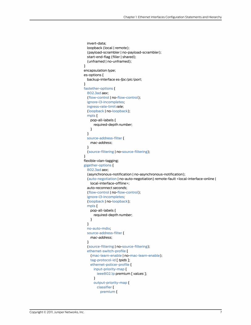
invert-data;loopback (local | remote);(payload-scrambler | no-payload-scrambler);start-end-flag (filler | shared);(unframed | no-unframed);
}encapsulation type;es-options {backup-interface es-fpc/pic/port;
}fastether-options {802.3ad aex;(flow-control | no-flow-control);ignore-l3-incompletes;ingress-rate-limit rate;(loopback | no-loopback);mpls {pop-all-labels {required-depth number;
}}source-address-filter {mac-address;
}(source-filtering | no-source-filtering);
}flexible-vlan-tagging;gigether-options {802.3ad aex;(asynchronous-notification | no-asynchronous-notification);(auto-negotiation | no-auto-negotiation) remote-fault <local-interface-online |local-interface-offline>;
auto-reconnect seconds;(flow-control | no-flow-control);ignore-l3-incompletes;(loopback | no-loopback);mpls {pop-all-labels {required-depth number;
}}no-auto-mdix;source-address-filter {mac-address;
}(source-filtering | no-source-filtering);ethernet-switch-profile {(mac-learn-enable | no-mac-learn-enable);tag-protocol-id [ tpids ];ethernet-policer-profile {input-priority-map {ieee802.1p premium [ values ];
}output-priority-map {classifier {premium {
7Copyright © 2011, Juniper Networks, Inc.
Chapter 1: Ethernet Interfaces Configuration Statements and Hierarchy

forwarding-class class-name {loss-priority (high | low);
}}
}}policer cos-policer-name {aggregate {bandwidth-limit bps;burst-size-limit bytes;
}premium {bandwidth-limit bps;burst-size-limit bytes;
}}
}}
}(gratuitous-arp-reply | no-gratuitous-arp-reply);hold-time upmilliseconds downmilliseconds;ima-group-options {differential-delay number;frame-length (32 | 64 | 128 | 256);frame-synchronization {alpha number;beta number;gamma number;
}minimum-links number;symmetry (symmetrical-config-and-operation |symmetrical-config-asymmetrical-operation);
test-procedure {ima-test-start;ima-test-stop;interface name;pattern number;period number;
}transmit-clock (common | independent);version (1.0 |1.1);
}ima-link-options group-id group-id;interface-set interface-set-name {interface ethernet-interface-name {(unit unit-number | vlan-tags-outer vlan-tag);
}interface interface-name {(unit unit-number);
}}isdn-options {bchannel-allocation (ascending | descending);calling-number number;pool pool-name <priority priority>;spid1 spid-string;
Copyright © 2011, Juniper Networks, Inc.8
Junos®
OS 11.4 Ethernet Interfaces Configuration Guide
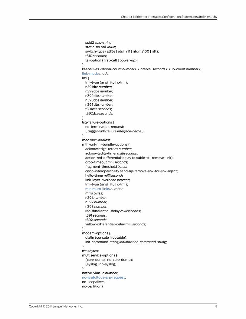
spid2 spid-string;static-tei-val value;switch-type (att5e | etsi | ni1 | ntdms100 | ntt);t310 seconds;tei-option (first-call | power-up);
}keepalives <down-count number> <interval seconds> <up-count number>;link-modemode;lmi {lmi-type (ansi | itu | c-lmi);n391dte number;n392dce number;n392dte number;n393dce number;n393dte number;t391dte seconds;t392dce seconds;
}lsq-failure-options {no-termination-request;[ trigger-link-failure interface-name ];
}macmac-address;mlfr-uni-nni-bundle-options {acknowledge-retries number;acknowledge-timermilliseconds;action-red-differential-delay (disable-tx | remove-link);drop-timeoutmilliseconds;fragment-threshold bytes;cisco-interoperability send-lip-remove-link-for-link-reject;hello-timermilliseconds;link-layer-overhead percent;lmi-type (ansi | itu | c-lmi);minimum-links number;mrru bytes;n391 number;n392 number;n393 number;red-differential-delaymilliseconds;t391 seconds;t392 seconds;yellow-differential-delaymilliseconds;
}modem-options {dialin (console | routable);init-command-string initialization-command-string;
}mtu bytes;multiservice-options {(core-dump | no-core-dump);(syslog | no-syslog);
}native-vlan-id number;no-gratuitous-arp-request;no-keepalives;no-partition {
9Copyright © 2011, Juniper Networks, Inc.
Chapter 1: Ethernet Interfaces Configuration Statements and Hierarchy

interface-type type;}otn-options {fec (efec | gfec | none);(laser-enable | no-laser-enable);(line-loopback | no-line-loopback);pass-thru;rate (fixed-stuff-bytes | no-fixed-stuff-bytes | pass-thru);transmit-payload-type number;trigger (oc-lof | oc-lom |oc-los | oc-wavelength-lock | odu-ais | odu-bbe-th | odu-bdi| odu-es-th | odu-lck | odu-oci | odu-sd | odu-ses-th | odu-ttim | odu-uas-th |opu-ptm | otu-ais | otu-bbe-th | otu-bdi | otu-es-th | otu-fec-deg | otu-fec-exe |otu-iae | otu-sd | otu-ses-th | otu-ttim | otu-uas-th);
tti;}optics-options {wavelength nm;alarm alarm-name {(syslog | link-down);
}warningwarning-name {(syslog | link-down);
}}partition partition-number oc-slice oc-slice-range interface-type type;timeslots time-slot-range;passive-monitor-mode;per-unit-scheduler;ppp-options {chap {access-profile name;default-chap-secret name;local-name name;passive;
}compression {acfc;pfc;
}dynamic-profile profile-name;no-termination-request;pap {access-profile name;local-name name;local-password password;compression;
}}receive-bucket {overflow (discard | tag);rate percentage;threshold bytes;
}redundancy-options {priority sp-fpc/pic/port;secondary sp-fpc/pic/port;
Copyright © 2011, Juniper Networks, Inc.10
Junos®
OS 11.4 Ethernet Interfaces Configuration Guide

hot-standby;}satop-options {payload-size n;
}schedulers number;serial-options {clock-rate rate;clocking-mode (dce | internal | loop);control-polarity (negative | positive);cts-polarity (negative | positive);dcd-polarity (negative | positive);dce-options {control-signal (assert | de-assert | normal);cts (ignore | normal | require);dcd (ignore | normal | require);dsr (ignore | normal | require);dtr signal-handling-option;ignore-all;indication (ignore | normal | require);rts (assert | de-assert | normal);tm (ignore | normal | require);
}dsr-polarity (negative | positive);dte-options {control-signal (assert | de-assert | normal);cts (ignore | normal | require);dcd (ignore | normal | require);dsr (ignore | normal | require);dtr signal-handling-option;ignore-all;indication (ignore | normal | require);rts (assert | de-assert | normal);tm (ignore | normal | require);
}dtr-circuit (balanced | unbalanced);dtr-polarity (negative | positive);encoding (nrz | nrzi);indication-polarity (negative | positive);line-protocol protocol;loopbackmode;rts-polarity (negative | positive);tm-polarity (negative | positive);transmit-clock invert;
}services-options {inactivity-timeout seconds;open-timeout seconds;session-limit {maximum number;rate new-sessions-per-second;}syslog {host hostname {facility-override facility-name;log-prefix prefix-number;
11Copyright © 2011, Juniper Networks, Inc.
Chapter 1: Ethernet Interfaces Configuration Statements and Hierarchy

services priority-level;}
}}shdsl-options {annex (annex-a | annex-b);line-rate line-rate;loopback (local | remote);snr-margin {currentmargin;snextmargin;
}}sonet-options {aggregate asx;aps {advertise-intervalmilliseconds;annex-b;authentication-key key;force;hold-timemilliseconds;lockout;neighbor address;paired-group group-name;preserve-interface;protect-circuit group-name;request;revert-time seconds;switching-mode (bidirectional | unidirectional);working-circuit group-name;
}bytes {c2 value;e1-quiet value;f1 value;f2 value;s1 value;z3 value;z4 value;
}fcs (16 | 32);loopback (local | remote);mpls {pop-all-labels {required-depth number;
}}path-trace trace-string;(payload-scrambler | no-payload-scrambler);rfc-2615;trigger {defect ignore;hold-time upmilliseconds downmilliseconds;
}vtmapping (itu-t | klm);(z0-increment | no-z0-increment);
Copyright © 2011, Juniper Networks, Inc.12
Junos®
OS 11.4 Ethernet Interfaces Configuration Guide
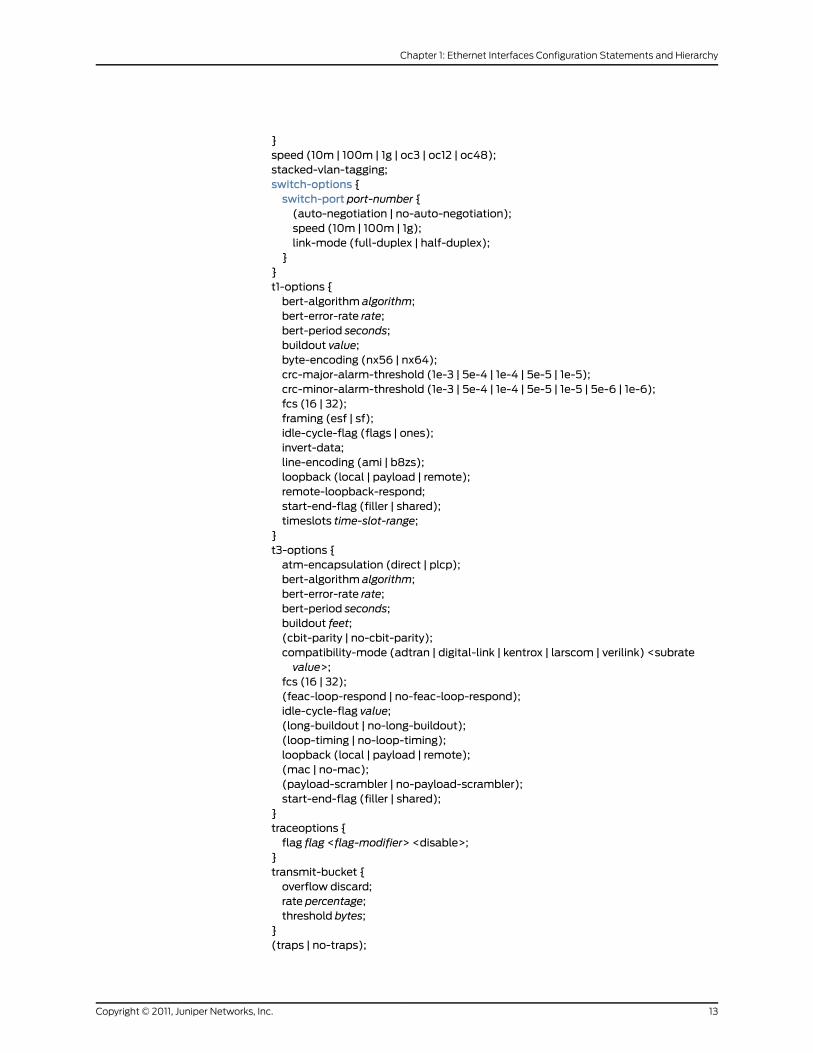
}speed (10m | 100m | 1g | oc3 | oc12 | oc48);stacked-vlan-tagging;switch-options {switch-port port-number {(auto-negotiation | no-auto-negotiation);speed (10m | 100m | 1g);link-mode (full-duplex | half-duplex);
}}t1-options {bert-algorithm algorithm;bert-error-rate rate;bert-period seconds;buildout value;byte-encoding (nx56 | nx64);crc-major-alarm-threshold (1e-3 | 5e-4 | 1e-4 | 5e-5 | 1e-5);crc-minor-alarm-threshold (1e-3 | 5e-4 | 1e-4 | 5e-5 | 1e-5 | 5e-6 | 1e-6);fcs (16 | 32);framing (esf | sf);idle-cycle-flag (flags | ones);invert-data;line-encoding (ami | b8zs);loopback (local | payload | remote);remote-loopback-respond;start-end-flag (filler | shared);timeslots time-slot-range;
}t3-options {atm-encapsulation (direct | plcp);bert-algorithm algorithm;bert-error-rate rate;bert-period seconds;buildout feet;(cbit-parity | no-cbit-parity);compatibility-mode (adtran | digital-link | kentrox | larscom | verilink) <subratevalue>;
fcs (16 | 32);(feac-loop-respond | no-feac-loop-respond);idle-cycle-flag value;(long-buildout | no-long-buildout);(loop-timing | no-loop-timing);loopback (local | payload | remote);(mac | no-mac);(payload-scrambler | no-payload-scrambler);start-end-flag (filler | shared);
}traceoptions {flag flag <flag-modifier> <disable>;
}transmit-bucket {overflow discard;rate percentage;threshold bytes;
}(traps | no-traps);
13Copyright © 2011, Juniper Networks, Inc.
Chapter 1: Ethernet Interfaces Configuration Statements and Hierarchy
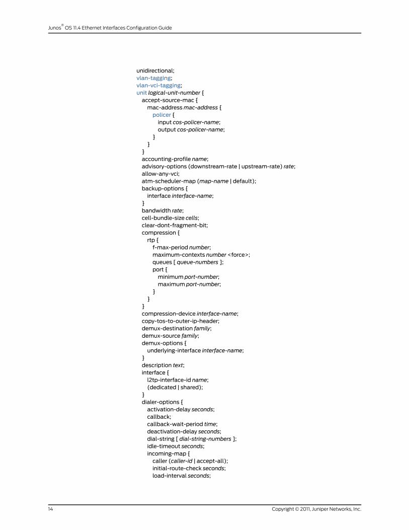
unidirectional;vlan-tagging;vlan-vci-tagging;unit logical-unit-number {accept-source-mac {mac-addressmac-address {policer {input cos-policer-name;output cos-policer-name;
}}
}accounting-profile name;advisory-options (downstream-rate | upstream-rate) rate;allow-any-vci;atm-scheduler-map (map-name | default);backup-options {interface interface-name;
}bandwidth rate;cell-bundle-size cells;clear-dont-fragment-bit;compression {rtp {f-max-period number;maximum-contexts number <force>;queues [ queue-numbers ];port {minimum port-number;maximum port-number;
}}
}compression-device interface-name;copy-tos-to-outer-ip-header;demux-destination family;demux-source family;demux-options {underlying-interface interface-name;
}description text;interface {l2tp-interface-id name;(dedicated | shared);
}dialer-options {activation-delay seconds;callback;callback-wait-period time;deactivation-delay seconds;dial-string [ dial-string-numbers ];idle-timeout seconds;incoming-map {caller (caller-id | accept-all);initial-route-check seconds;load-interval seconds;
Copyright © 2011, Juniper Networks, Inc.14
Junos®
OS 11.4 Ethernet Interfaces Configuration Guide

load-threshold percent;pool pool-name;redial-delay time;watch-list {[ routes ];
}}
}disable;disable-mlppp-inner-ppp-pfc;dlci dlci-identifier;drop-timeoutmilliseconds;dynamic-call-admission-control {activation-priority priority;bearer-bandwidth-limit kilobits-per-second;
}encapsulation type;epd-threshold cells plp1 cells;fragment-threshold bytes;inner-vlan-id-range start start-id end end-id;input-vlan-map {(pop |pop-pop |pop-swap |push |push-push | swap | swap-push | swap-swap);inner-tag-protocol-id tpid;inner-vlan-id number;tag-protocol-id tpid;vlan-id number;
}interleave-fragments;inverse-arp;layer2-policer {input-policer policer-name;input-three-color policer-name;output-policer policer-name;output-three-color policer-name;
}link-layer-overhead percent;minimum-links number;mrru bytes;multicast-dlci dlci-identifier;multicast-vci vpi-identifier.vci-identifier;multilink-max-classes number;multipoint;oam-liveness {down-count cells;up-count cells;
}oam-period (seconds | disable);output-vlan-map {(pop |pop-pop |pop-swap |push |push-push | swap | swap-push | swap-swap);inner-tag-protocol-id tpid;inner-vlan-id number;tag-protocol-id tpid;vlan-id number;
}passive-monitor-mode;peer-unit unit-number;
15Copyright © 2011, Juniper Networks, Inc.
Chapter 1: Ethernet Interfaces Configuration Statements and Hierarchy

plp-to-clp;point-to-point;ppp-options {chap {access-profile name;default-chap-secret name;local-name name;passive;
}compression {acfc;pfc;pap;default-pap-password password;local-name name;local-password password;passive;
}dynamic-profile profile-name;lcp-max-conf-req number;lcp-restart-timermilliseconds;loopback-clear-timer seconds;ncp-max-conf-req number;ncp-restart-timermilliseconds;
}pppoe-options {access-concentrator name;auto-reconnect seconds;(client | server);service-name name;underlying-interface interface-name;
}proxy-arp;service-domain (inside | outside);shaping {(cbr rate | rtvbr peak rate sustained rate burst length | vbr peak rate sustained rateburst length);
queue-length number;}short-sequence;transmit-weight number;(traps | no-traps);trunk-bandwidth rate;trunk-id number;tunnel {backup-destination address;destination address;key number;routing-instance {destination routing-instance-name;
}source source-address;ttl number;
}vci vpi-identifier.vci-identifier;vci-range start start-vci end end-vci;
Copyright © 2011, Juniper Networks, Inc.16
Junos®
OS 11.4 Ethernet Interfaces Configuration Guide

vpi vpi-identifier;vlan-id number;vlan-id-list [vlan-id vlan-id–vlan-id];vlan-id-range number-number;vlan-tags inner tpid.vlan-id outer tpid.vlan-id;vlan-tags-outer tpid.vlan-id inner-list [vlan-id vlan-id–vlan-id];family family {accounting {destination-class-usage;source-class-usage {direction;
}}access-concentrator name;address address {destination address;
}bundleml-fpc/pic/port | ls-fpc/pic/port);duplicate-protection;dynamic-profile profile-name;filter {group filter-group-number;input filter-name;input-list {[ filter-names ];output filter-name;
}output-list {[ filter-names ];
}}ipsec-sa sa-name;keep-address-and-control;max-sessions number;max-sessions-vsa-ignore;mtu bytes;multicast-only;negotiate-address;no-redirects;policer {arp policer-template-name;input policer-template-name;output policer-template-name;
}primary;proxy inet-address address;receive-options-packets;receive-ttl-exceeded;remote (inet-address address | mac-address address);rpf-check {fail-filter filter-name;mode loose;
}sampling {direction;
}
17Copyright © 2011, Juniper Networks, Inc.
Chapter 1: Ethernet Interfaces Configuration Statements and Hierarchy
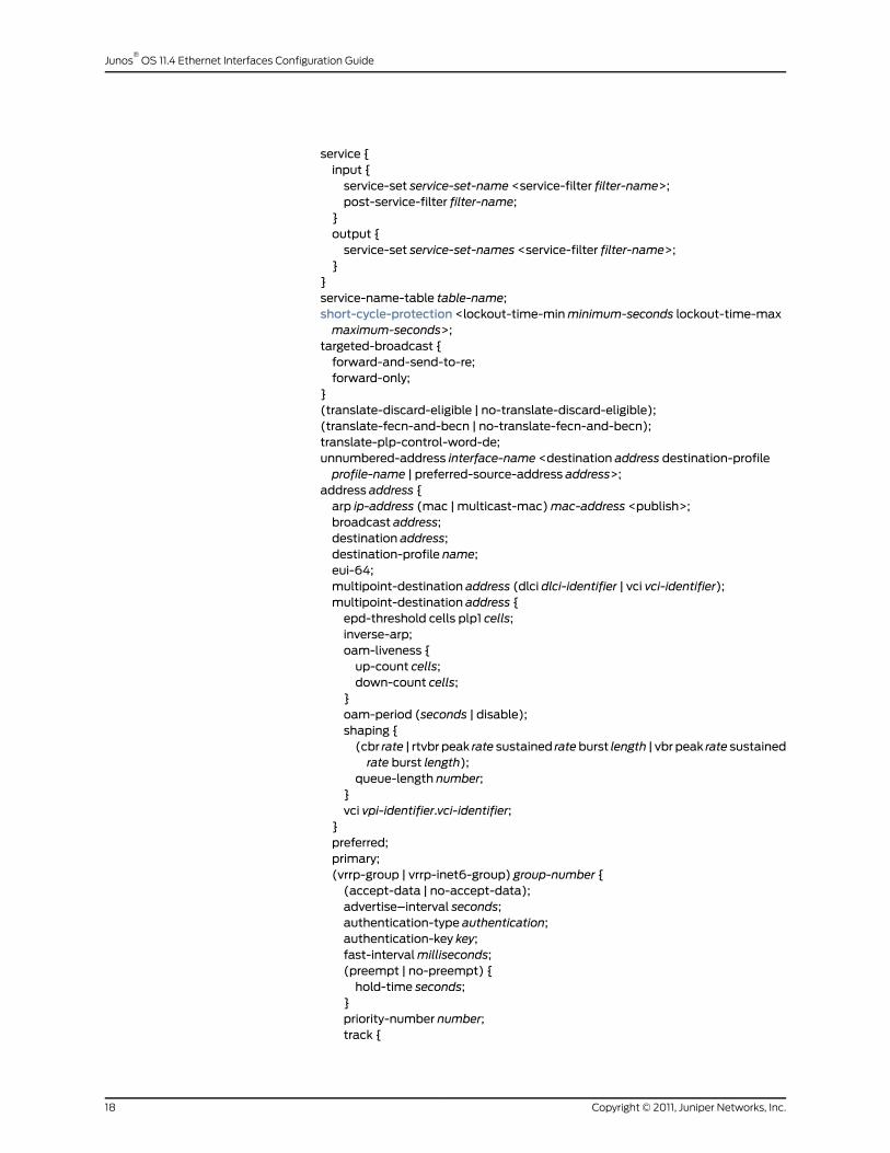
service {input {service-set service-set-name <service-filter filter-name>;post-service-filter filter-name;
}output {service-set service-set-names <service-filter filter-name>;
}}service-name-table table-name;short-cycle-protection <lockout-time-minminimum-seconds lockout-time-maxmaximum-seconds>;
targeted-broadcast {forward-and-send-to-re;forward-only;
}(translate-discard-eligible | no-translate-discard-eligible);(translate-fecn-and-becn | no-translate-fecn-and-becn);translate-plp-control-word-de;unnumbered-address interface-name <destination address destination-profileprofile-name | preferred-source-address address>;
address address {arp ip-address (mac | multicast-mac)mac-address <publish>;broadcast address;destination address;destination-profile name;eui-64;multipoint-destination address (dlci dlci-identifier | vci vci-identifier);multipoint-destination address {epd-threshold cells plp1 cells;inverse-arp;oam-liveness {up-count cells;down-count cells;
}oam-period (seconds | disable);shaping {(cbr rate | rtvbr peak rate sustained rateburst length | vbr peak rate sustainedrate burst length);
queue-length number;}vci vpi-identifier.vci-identifier;
}preferred;primary;(vrrp-group | vrrp-inet6-group) group-number {(accept-data | no-accept-data);advertise–interval seconds;authentication-type authentication;authentication-key key;fast-intervalmilliseconds;(preempt | no-preempt) {hold-time seconds;
}priority-number number;track {
Copyright © 2011, Juniper Networks, Inc.18
Junos®
OS 11.4 Ethernet Interfaces Configuration Guide
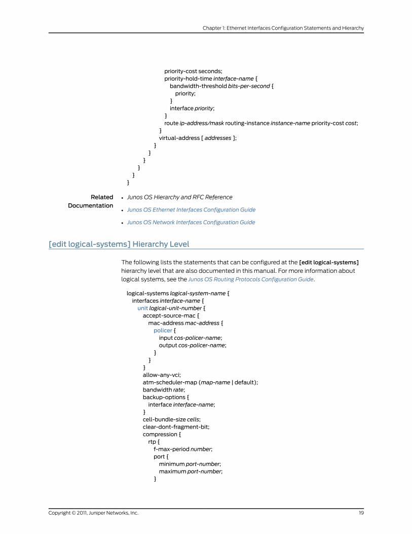
priority-cost seconds;priority-hold-time interface-name {bandwidth-threshold bits-per-second {priority;
}interface priority;
}route ip-address/mask routing-instance instance-name priority-cost cost;
}virtual-address [ addresses ];
}}
}}
}}
RelatedDocumentation
Junos OS Hierarchy and RFC Reference•
• Junos OS Ethernet Interfaces Configuration Guide
• Junos OS Network Interfaces Configuration Guide
[edit logical-systems] Hierarchy Level
The following lists the statements that can be configured at the [edit logical-systems]
hierarchy level that are also documented in this manual. For more information about
logical systems, see the Junos OS Routing Protocols Configuration Guide.
logical-systems logical-system-name {interfaces interface-name {unit logical-unit-number {accept-source-mac {mac-addressmac-address {policer {input cos-policer-name;output cos-policer-name;
}}
}allow-any-vci;atm-scheduler-map (map-name | default);bandwidth rate;backup-options {interface interface-name;
}cell-bundle-size cells;clear-dont-fragment-bit;compression {rtp {f-max-period number;port {minimum port-number;maximum port-number;
}
19Copyright © 2011, Juniper Networks, Inc.
Chapter 1: Ethernet Interfaces Configuration Statements and Hierarchy
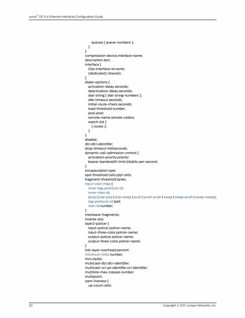
queues [ queue-numbers ];}
}compression-device interface-name;description text;interface {l2tp-interface-id name;(dedicated | shared);
}dialer-options {activation-delay seconds;deactivation-delay seconds;dial-string [ dial-string-numbers ];idle-timeout seconds;initial-route-check seconds;load-threshold number;pool pool;remote-name remote-callers;watch-list {[ routes ];
}}disable;dlci dlci-identifier;drop-timeoutmilliseconds;dynamic-call-admission-control {activation-priority priority;bearer-bandwidth-limit kilobits-per-second;
}encapsulation type;epd-threshold cells plp1 cells;fragment-threshold bytes;input-vlan-map {inner-tag-protocol-id;inner-vlan-id;(pop |pop-pop |pop-swap |push |push-push | swap | swap-push | swap-swap);tag-protocol-id tpid;vlan-id number;
}interleave-fragments;inverse-arp;layer2-policer {input-policer policer-name;input-three-color policer-name;output-policer policer-name;output-three-color policer-name;
}link-layer-overhead percent;minimum-links number;mrru bytes;multicast-dlci dlci-identifier;multicast-vci vpi-identifier.vci-identifier;multilink-max-classes number;multipoint;oam-liveness {up-count cells;
Copyright © 2011, Juniper Networks, Inc.20
Junos®
OS 11.4 Ethernet Interfaces Configuration Guide
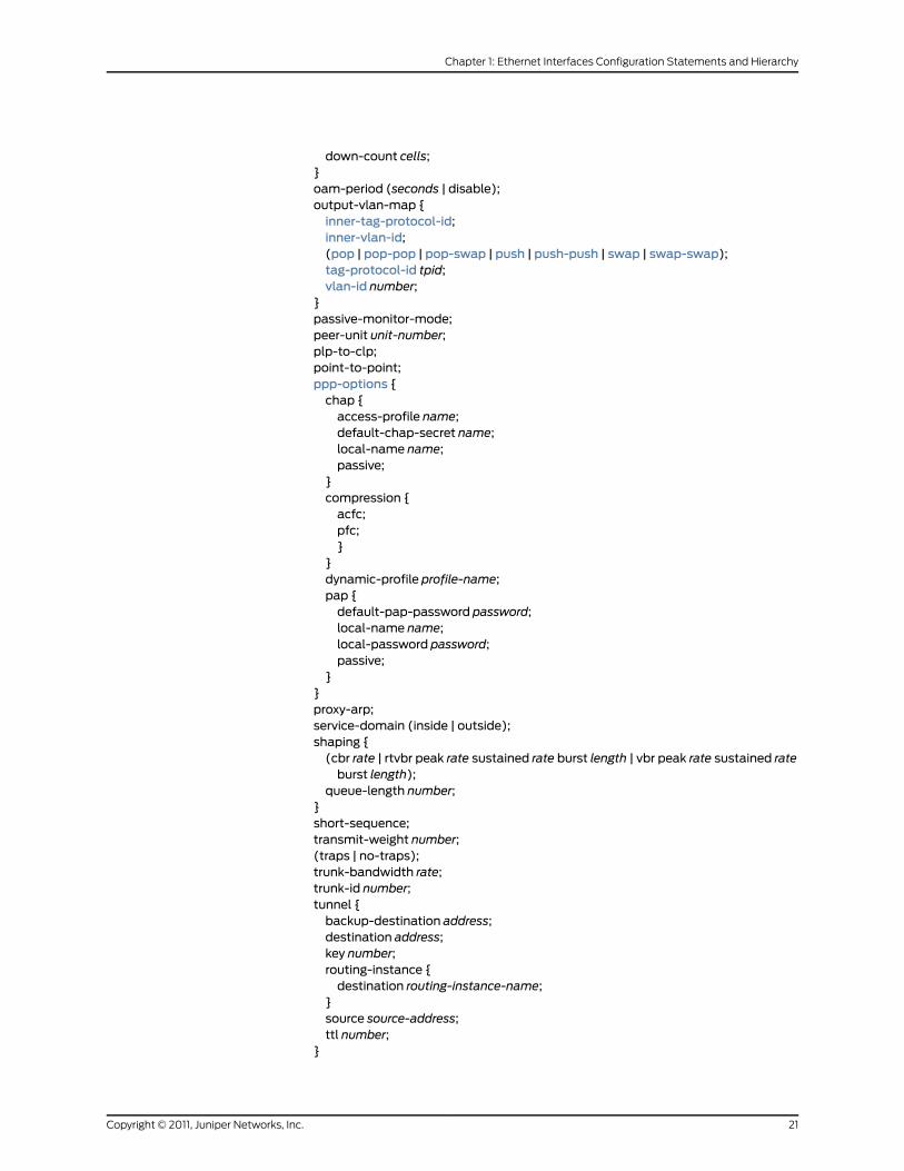
down-count cells;}oam-period (seconds | disable);output-vlan-map {inner-tag-protocol-id;inner-vlan-id;(pop | pop-pop | pop-swap | push | push-push | swap | swap-swap);tag-protocol-id tpid;vlan-id number;
}passive-monitor-mode;peer-unit unit-number;plp-to-clp;point-to-point;ppp-options {chap {access-profile name;default-chap-secret name;local-name name;passive;
}compression {acfc;pfc;}
}dynamic-profile profile-name;pap {default-pap-password password;local-name name;local-password password;passive;
}}proxy-arp;service-domain (inside | outside);shaping {(cbr rate | rtvbr peak rate sustained rate burst length | vbr peak rate sustained rateburst length);
queue-length number;}short-sequence;transmit-weight number;(traps | no-traps);trunk-bandwidth rate;trunk-id number;tunnel {backup-destination address;destination address;key number;routing-instance {destination routing-instance-name;
}source source-address;ttl number;
}
21Copyright © 2011, Juniper Networks, Inc.
Chapter 1: Ethernet Interfaces Configuration Statements and Hierarchy
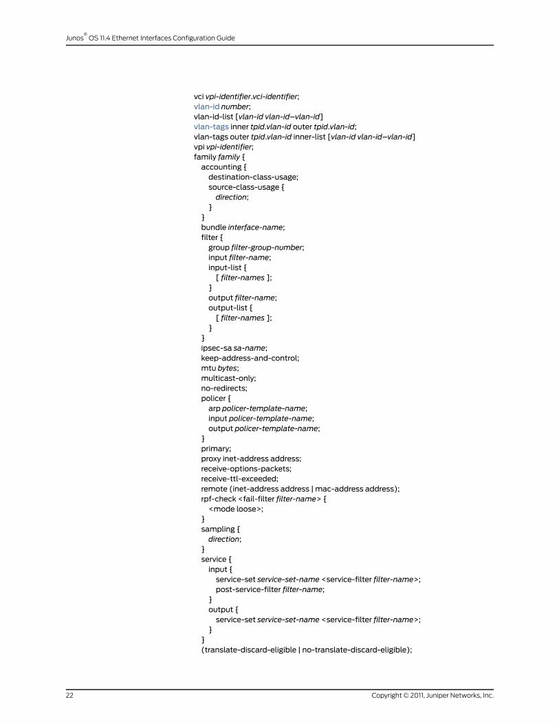
vci vpi-identifier.vci-identifier;vlan-id number;vlan-id-list [vlan-id vlan-id–vlan-id]vlan-tags inner tpid.vlan-id outer tpid.vlan-id;vlan-tags outer tpid.vlan-id inner-list [vlan-id vlan-id–vlan-id]vpi vpi-identifier;family family {accounting {destination-class-usage;source-class-usage {direction;
}}bundle interface-name;filter {group filter-group-number;input filter-name;input-list {[ filter-names ];
}output filter-name;output-list {[ filter-names ];
}}ipsec-sa sa-name;keep-address-and-control;mtu bytes;multicast-only;no-redirects;policer {arp policer-template-name;input policer-template-name;output policer-template-name;
}primary;proxy inet-address address;receive-options-packets;receive-ttl-exceeded;remote (inet-address address | mac-address address);rpf-check <fail-filter filter-name> {<mode loose>;
}sampling {direction;
}service {input {service-set service-set-name <service-filter filter-name>;post-service-filter filter-name;
}output {service-set service-set-name <service-filter filter-name>;
}}(translate-discard-eligible | no-translate-discard-eligible);
Copyright © 2011, Juniper Networks, Inc.22
Junos®
OS 11.4 Ethernet Interfaces Configuration Guide
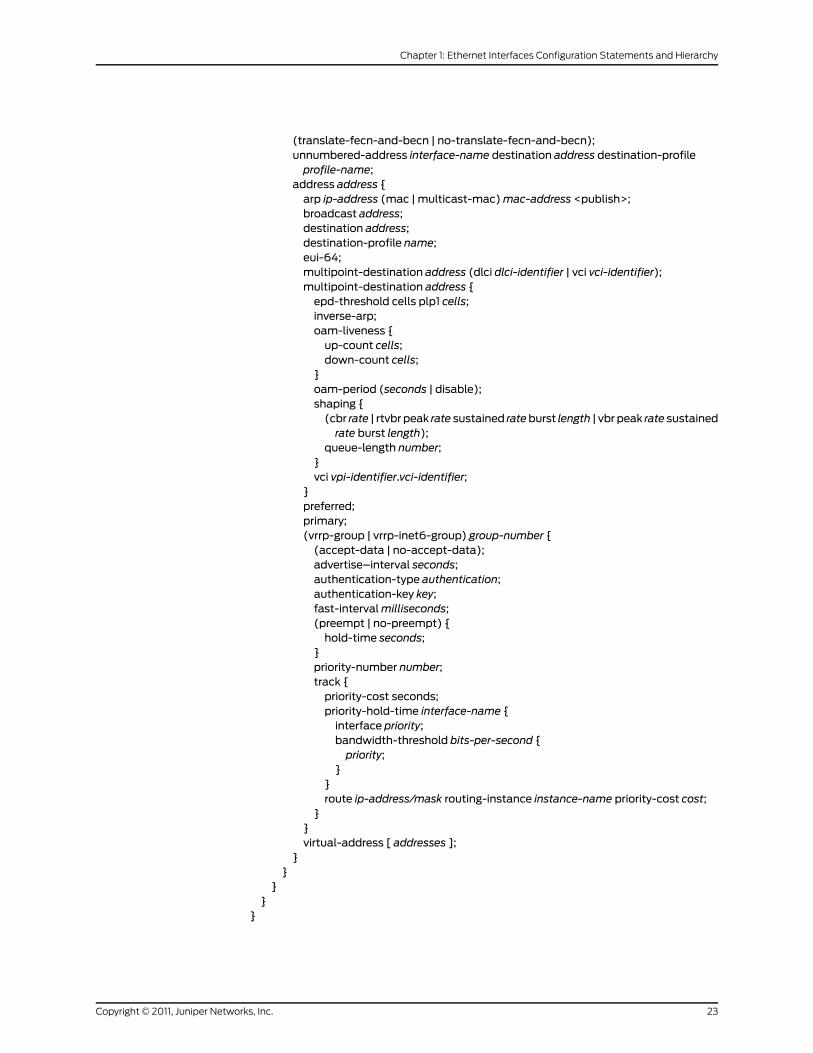
(translate-fecn-and-becn | no-translate-fecn-and-becn);unnumbered-address interface-name destination address destination-profileprofile-name;
address address {arp ip-address (mac | multicast-mac)mac-address <publish>;broadcast address;destination address;destination-profile name;eui-64;multipoint-destination address (dlci dlci-identifier | vci vci-identifier);multipoint-destination address {epd-threshold cells plp1 cells;inverse-arp;oam-liveness {up-count cells;down-count cells;
}oam-period (seconds | disable);shaping {(cbr rate | rtvbr peak rate sustained rateburst length | vbr peak rate sustainedrate burst length);
queue-length number;}vci vpi-identifier.vci-identifier;
}preferred;primary;(vrrp-group | vrrp-inet6-group) group-number {(accept-data | no-accept-data);advertise–interval seconds;authentication-type authentication;authentication-key key;fast-intervalmilliseconds;(preempt | no-preempt) {hold-time seconds;
}priority-number number;track {priority-cost seconds;priority-hold-time interface-name {interface priority;bandwidth-threshold bits-per-second {priority;
}}route ip-address/mask routing-instance instance-name priority-cost cost;
}}virtual-address [ addresses ];
}}
}}
}
23Copyright © 2011, Juniper Networks, Inc.
Chapter 1: Ethernet Interfaces Configuration Statements and Hierarchy

RelatedDocumentation
Junos OS Hierarchy and RFC Reference•
• Junos OS Ethernet Interfaces Configuration Guide
• Junos OS Network Interfaces Configuration Guide
[edit protocols connections] Hierarchy Level
The following statements can also be configured at the [edit logical-systems
logical-system-name protocols connections] hierarchy level.
interface-switch connection-name {interface interface-name.unit-number;interface interface-name.unit-number;
}
Copyright © 2011, Juniper Networks, Inc.24
Junos®
OS 11.4 Ethernet Interfaces Configuration Guide
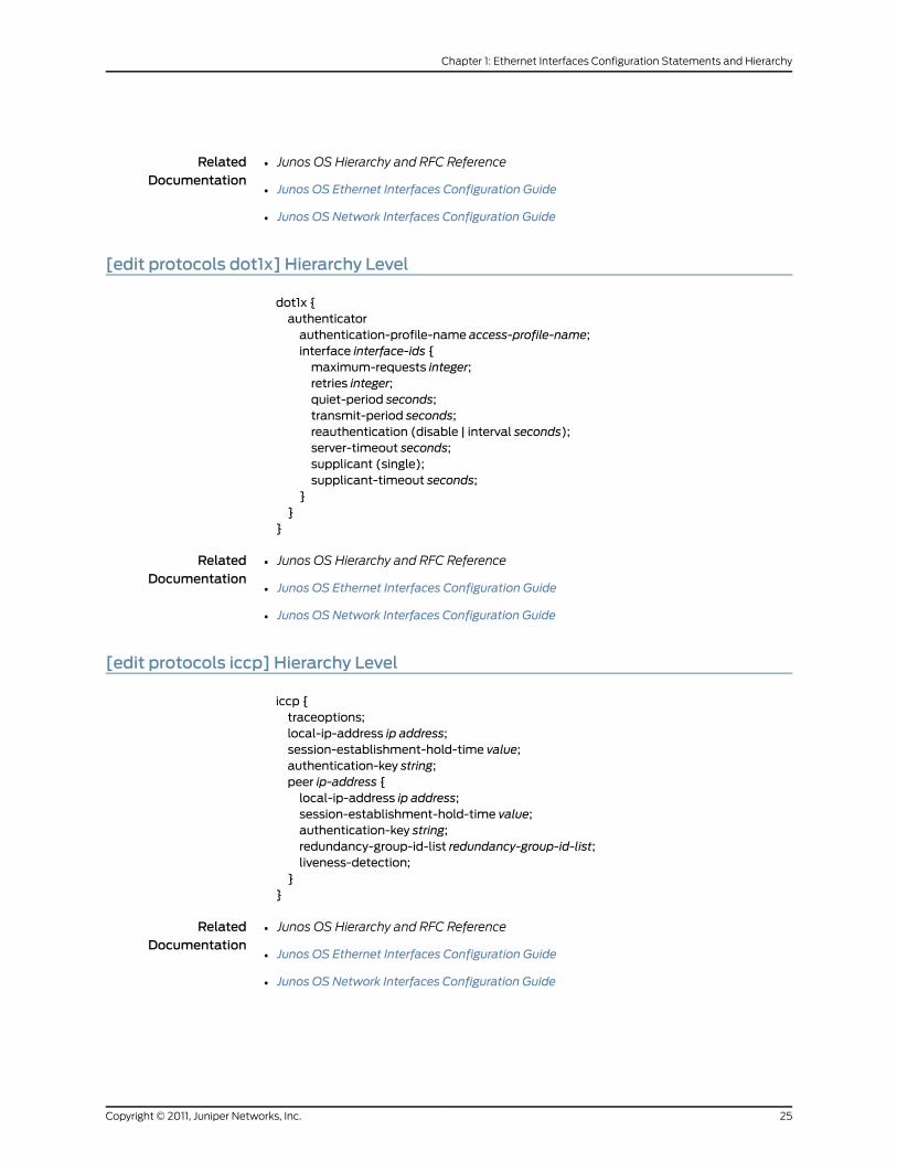
RelatedDocumentation
Junos OS Hierarchy and RFC Reference•
• Junos OS Ethernet Interfaces Configuration Guide
• Junos OS Network Interfaces Configuration Guide
[edit protocols dot1x] Hierarchy Level
dot1x {authenticatorauthentication-profile-name access-profile-name;interface interface-ids {maximum-requests integer;retries integer;quiet-period seconds;transmit-period seconds;reauthentication (disable | interval seconds);server-timeout seconds;supplicant (single);supplicant-timeout seconds;
}}
}
RelatedDocumentation
Junos OS Hierarchy and RFC Reference•
• Junos OS Ethernet Interfaces Configuration Guide
• Junos OS Network Interfaces Configuration Guide
[edit protocols iccp] Hierarchy Level
iccp {traceoptions;local-ip-address ip address;session-establishment-hold-time value;authentication-key string;peer ip-address {local-ip-address ip address;session-establishment-hold-time value;authentication-key string;redundancy-group-id-list redundancy-group-id-list;liveness-detection;
}}
RelatedDocumentation
Junos OS Hierarchy and RFC Reference•
• Junos OS Ethernet Interfaces Configuration Guide
• Junos OS Network Interfaces Configuration Guide
25Copyright © 2011, Juniper Networks, Inc.
Chapter 1: Ethernet Interfaces Configuration Statements and Hierarchy
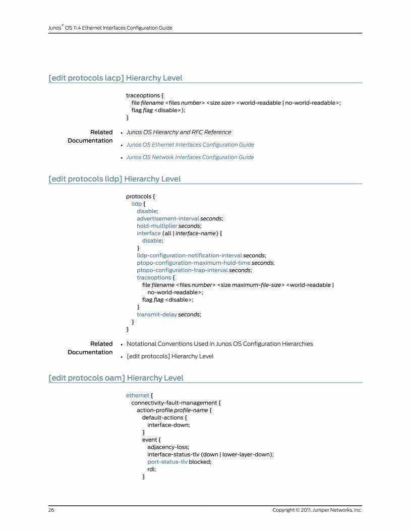
[edit protocols lacp] Hierarchy Level
traceoptions {file filename <files number> <size size> <world-readable | no-world-readable>;flag flag <disable>);
}
RelatedDocumentation
Junos OS Hierarchy and RFC Reference•
• Junos OS Ethernet Interfaces Configuration Guide
• Junos OS Network Interfaces Configuration Guide
[edit protocols lldp] Hierarchy Level
protocols {lldp {disable;advertisement-interval seconds;hold-multiplier seconds;interface (all | interface-name) {disable;
}lldp-configuration-notification-interval seconds;ptopo-configuration-maximum-hold-time seconds;ptopo-configuration-trap-interval seconds;traceoptions {file filename <files number> <sizemaximum-file-size> <world-readable |no-world-readable>;
flag flag <disable>;}transmit-delay seconds;
}}
RelatedDocumentation
Notational Conventions Used in Junos OS Configuration Hierarchies•
• [edit protocols] Hierarchy Level
[edit protocols oam] Hierarchy Level
ethernet {connectivity-fault-management {action-profile profile-name {default-actions {interface-down;
}event {adjacency-loss;interface-status-tlv (down | lower-layer-down);port-status-tlv blocked;rdi;
}
Copyright © 2011, Juniper Networks, Inc.26
Junos®
OS 11.4 Ethernet Interfaces Configuration Guide

}linktrace {age (30m | 10m | 1m | 30s | 10s);path-database-size path-database-size;
}maintenance-domain domain-name {bridge-domain name;routing-instance r1 {bridge-domain name;instance vpls-instance;interface (ge | xe) fpc/pic/port.domain;level number;maintenance-association name{mep identifier {direction (up | down)interface (ge | xe) fpc/pic/port.domain (working | protect );auto-discovery;lowest-priority-defect (all-defects | err-xcon | mac-rem-err-xcon | no-defect |rem-err-xcon | xcon);
priority number;}
}mip-half-function (none | default | explicit);name-format (character-string | none | dns | mac+2oct);short-name-format (character-string | vlan | 2octet | rfc-2685-vpn-id);protect-maintenance-associationprotect-ma-name;remote-maintenance-associationremote-ma-name;continuity-check {hold-intervalminutes;interval (10m | 10s | 1m | 1s | 100ms);loss-threshold number;
}maintenance-associationma-name {mip-half-function (none | default | explicit);mepmep-id {auto-discovery;direction (up | down);interfaceinterface-name (working |protect);priority number;remote-mepmep-id {action-profile profile-name;sla-iterator-profile profile-name {data-tlv-size bytes;iteration-count frames;priority priority-value;
}}
}}
}performance-monitoring {hardware-assisted-timestamping;sla-iterator-profiles {profile-name {disable;calculation-weight {
27Copyright © 2011, Juniper Networks, Inc.
Chapter 1: Ethernet Interfaces Configuration Statements and Hierarchy

delay delay-weight;delay-variation delay-variation-weight;
}cycle-timemilliseconds;iteration-period connections;measurement-type (loss | statistical-frame-loss | two-way-delay);
}}
}}link-fault-management {action-profile profile-name {action {syslog;link-down;send-critical-event;
}event {link-adjacency-loss;link-event-rate {frame-error count;frame-period count;frame-period-summary count;symbol-period count;
}protocol-down;
}}interface interface-name {apply-action-profile profile-name;event-thresholds {frame-error count;frame-period count;frame-period-summary count;symbol-period count;
}link-discovery (active | passive);negotiation-options {allow-remote-loopback;no-allow-link-events;
}pdu-interval interval;pdu-threshold threshold-value;remote-loopback;
}}fnp {interval <100ms | 1s | 10s | 1m | 10m>;loss-threshold numberinterface interface name {
domain-id domain-id}
}}
Copyright © 2011, Juniper Networks, Inc.28
Junos®
OS 11.4 Ethernet Interfaces Configuration Guide

RelatedDocumentation
Junos OS Hierarchy and RFC Reference•
• Junos OS Ethernet Interfaces Configuration Guide
• Junos OS Network Interfaces Configuration Guide
[edit protocols ppp] Hierarchy Level
monitor-session (interface-name | all);traceoptions {file filename <files number> <match regular-expression> <size size> <world-readable |no-world-readable> ;
flag flag <disable>;}
RelatedDocumentation
Junos OS Hierarchy and RFC Reference•
• Junos OS Ethernet Interfaces Configuration Guide
• Junos OS Network Interfaces Configuration Guide
[edit protocols pppoe] Hierarchy Level
protocols {pppoe {pado-advertise;service-name-tables table-name {service service-name {agent-specifier {aci circuit-id-string ari remote-id-string {(delay seconds | drop | terminate);dynamic-profile profile-name;routing-instance routing-instance-name;static-interface interface-name;
}}(delay seconds | drop | terminate);dynamic-profile profile-name;max-sessions number;routing-instance routing-instance-name;
}}traceoptions {file<filename><filesnumber><match regular-expression><sizemaximum-file-size><world-readable | no-world-readable>;
flag flag;level (all | error | info | notice | verbose | warning);no-remote-trace;
}}
}
RelatedDocumentation
Notational Conventions Used in Junos OS Configuration Hierarchies•
29Copyright © 2011, Juniper Networks, Inc.
Chapter 1: Ethernet Interfaces Configuration Statements and Hierarchy
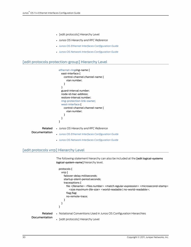
• [edit protocols] Hierarchy Level
• Junos OS Hierarchy and RFC Reference
• Junos OS Ethernet Interfaces Configuration Guide
• Junos OS Network Interfaces Configuration Guide
[edit protocols protection-group] Hierarchy Level
ethernet-ringring-name {east-interface {control-channel channel-name {vlan number;
}}guard-interval number;node-idmac-address;restore-interval number;ring-protection-link-owner;west-interface {control-channel channel-name {vlan number;
}}
}
RelatedDocumentation
Junos OS Hierarchy and RFC Reference•
• Junos OS Ethernet Interfaces Configuration Guide
• Junos OS Network Interfaces Configuration Guide
[edit protocols vrrp] Hierarchy Level
The following statement hierarchy can also be included at the [edit logical-systems
logical-system-name] hierarchy level.
protocols {vrrp {failover-delaymilliseconds;startup-silent-period seconds;traceoptions {file <filename> <files number> <match regular-expression> <microsecond-stamp><sizemaximum-file-size> <world-readable | no-world-readable>;
flag flag;no-remote-trace;
}}
}
RelatedDocumentation
• Notational Conventions Used in Junos OS Configuration Hierarchies
• [edit protocols] Hierarchy Level
Copyright © 2011, Juniper Networks, Inc.30
Junos®
OS 11.4 Ethernet Interfaces Configuration Guide

• Junos OS Hierarchy and RFC Reference
• Junos OS Ethernet Interfaces Configuration Guide
• Junos OS Network Interfaces Configuration Guide
31Copyright © 2011, Juniper Networks, Inc.
Chapter 1: Ethernet Interfaces Configuration Statements and Hierarchy

Copyright © 2011, Juniper Networks, Inc.32
Junos®
OS 11.4 Ethernet Interfaces Configuration Guide
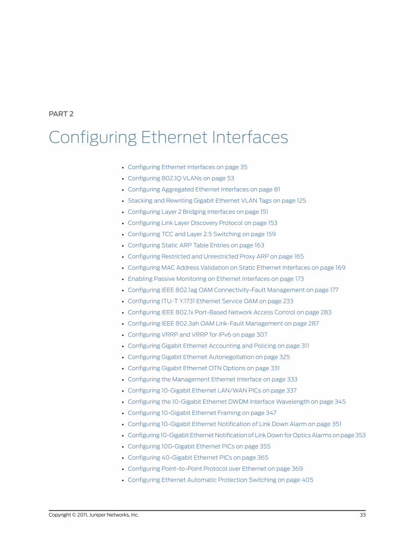
PART 2
Configuring Ethernet Interfaces
• Configuring Ethernet Interfaces on page 35
• Configuring 802.1Q VLANs on page 53
• Configuring Aggregated Ethernet Interfaces on page 81
• Stacking and Rewriting Gigabit Ethernet VLAN Tags on page 125
• Configuring Layer 2 Bridging Interfaces on page 151
• Configuring Link Layer Discovery Protocol on page 153
• Configuring TCC and Layer 2.5 Switching on page 159
• Configuring Static ARP Table Entries on page 163
• Configuring Restricted and Unrestricted Proxy ARP on page 165
• Configuring MAC Address Validation on Static Ethernet Interfaces on page 169
• Enabling Passive Monitoring on Ethernet Interfaces on page 173
• Configuring IEEE 802.1ag OAM Connectivity-Fault Management on page 177
• Configuring ITU-T Y.1731 Ethernet Service OAM on page 233
• Configuring IEEE 802.1x Port-Based Network Access Control on page 283
• Configuring IEEE 802.3ah OAM Link-Fault Management on page 287
• Configuring VRRP and VRRP for IPv6 on page 307
• Configuring Gigabit Ethernet Accounting and Policing on page 311
• Configuring Gigabit Ethernet Autonegotiation on page 325
• Configuring Gigabit Ethernet OTN Options on page 331
• Configuring the Management Ethernet Interface on page 333
• Configuring 10-Gigabit Ethernet LAN/WAN PICs on page 337
• Configuring the 10-Gigabit Ethernet DWDM Interface Wavelength on page 345
• Configuring 10-Gigabit Ethernet Framing on page 347
• Configuring 10-Gigabit Ethernet Notification of Link Down Alarm on page 351
• Configuring 10-Gigabit Ethernet Notification of Link Down for Optics Alarms on page 353
• Configuring 100-Gigabit Ethernet PICs on page 355
• Configuring 40-Gigabit Ethernet PICs on page 365
• Configuring Point-to-Point Protocol over Ethernet on page 369
• Configuring Ethernet Automatic Protection Switching on page 405
33Copyright © 2011, Juniper Networks, Inc.

• Configuring Ethernet Ring Protection Switching on page 413
• Example Ethernet Configurations on page 427
Copyright © 2011, Juniper Networks, Inc.34
Junos®
OS 11.4 Ethernet Interfaces Configuration Guide

CHAPTER 2
Configuring Ethernet Interfaces
You can configure the following properties specific to aggregated Ethernet, Fast Ethernet,
Tri-Rate Ethernet copper, Gigabit Ethernet, and 10-Gigabit Ethernet interfaces:
• Ethernet Interfaces Overview on page 35
• Configuring Ethernet Physical Interface Properties on page 36
• Configuring J Series Services Router Switching Interfaces on page 40
• MX Series Router Interface Identifiers on page 42
• Enabling Ethernet MAC Address Filtering on page 42
• Configuring Ethernet Loopback Capability on page 44
• Configuring Flow Control on page 45
• Ignoring Layer 3 Incomplete Errors on page 46
• Configuring the Link Characteristics on Ethernet Interfaces on page 46
• Configuring Gratuitous ARP on page 47
• Adjusting the ARP Aging Timer on page 48
• Configuring the Interface Speed on Ethernet Interfaces on page 49
• Configuring the Ingress Rate Limit on page 50
• Configuring Multicast Statistics Collection on Ethernet Interfaces on page 50
• Configuring Weighted Random Early Detection on page 51
Ethernet Interfaces Overview
Ethernet was developed in the early 1970s at the Xerox Palo Alto Research Center (PARC)
as a data-link control layer protocol for interconnecting computers. It was first widely
used at 10 megabits per second (Mbps) over coaxial cables and later over unshielded
twisted pairs using 10Base-T. More recently, 100Base-TX (Fast Ethernet, 100 Mbps),
Gigabit Ethernet (1 gigabit per second [Gbps]), 10-Gigabit Ethernet (10 Gbps), and
100-Gigabit Ethernet (100 Gbps) have become available.
Juniper Networks routers support the following types of Ethernet interfaces:
• Fast Ethernet
• Tri-Rate Ethernet copper
35Copyright © 2011, Juniper Networks, Inc.
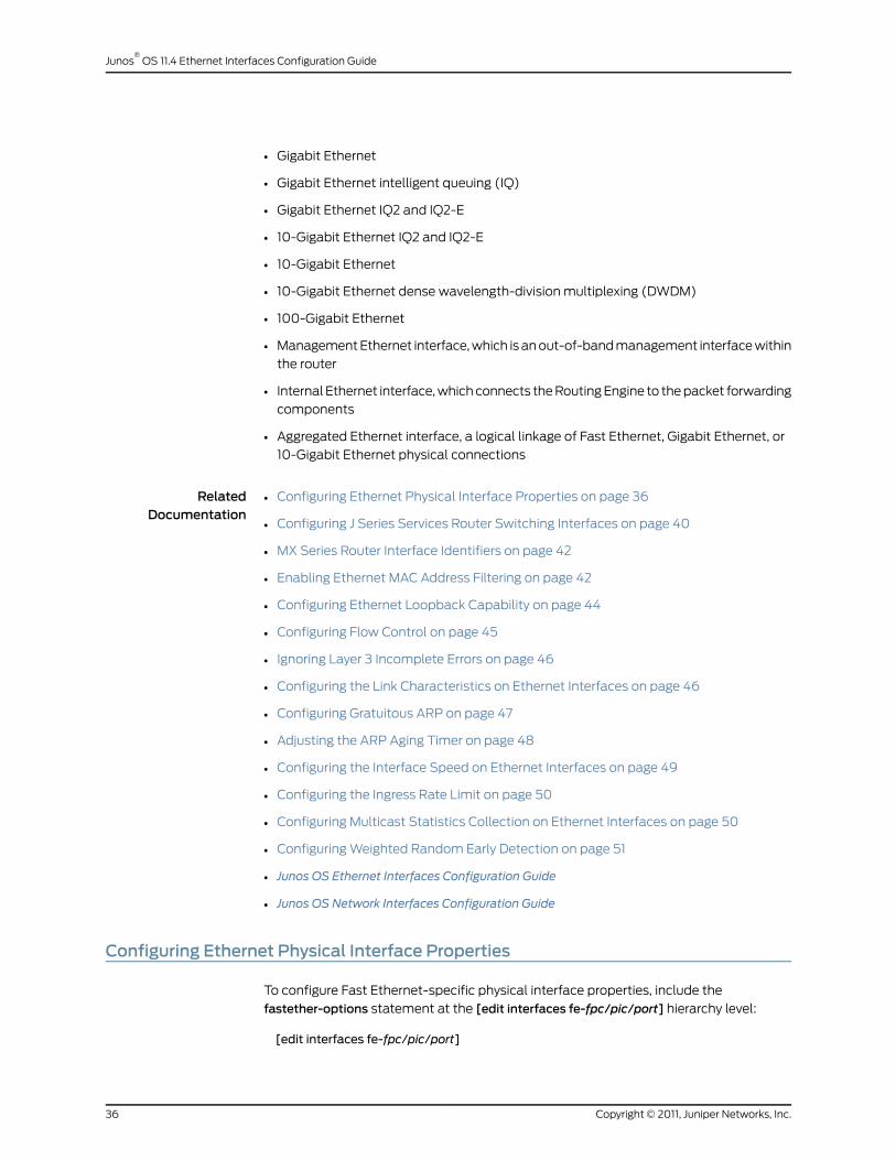
• Gigabit Ethernet
• Gigabit Ethernet intelligent queuing (IQ)
• Gigabit Ethernet IQ2 and IQ2-E
• 10-Gigabit Ethernet IQ2 and IQ2-E
• 10-Gigabit Ethernet
• 10-Gigabit Ethernet dense wavelength-division multiplexing (DWDM)
• 100-Gigabit Ethernet
• Management Ethernet interface, which is an out-of-band management interface within
the router
• Internal Ethernet interface, which connects the Routing Engine to the packet forwarding
components
• Aggregated Ethernet interface, a logical linkage of Fast Ethernet, Gigabit Ethernet, or
10-Gigabit Ethernet physical connections
RelatedDocumentation
Configuring Ethernet Physical Interface Properties on page 36•
• Configuring J Series Services Router Switching Interfaces on page 40
• MX Series Router Interface Identifiers on page 42
• Enabling Ethernet MAC Address Filtering on page 42
• Configuring Ethernet Loopback Capability on page 44
• Configuring Flow Control on page 45
• Ignoring Layer 3 Incomplete Errors on page 46
• Configuring the Link Characteristics on Ethernet Interfaces on page 46
• Configuring Gratuitous ARP on page 47
• Adjusting the ARP Aging Timer on page 48
• Configuring the Interface Speed on Ethernet Interfaces on page 49
• Configuring the Ingress Rate Limit on page 50
• Configuring Multicast Statistics Collection on Ethernet Interfaces on page 50
• Configuring Weighted Random Early Detection on page 51
• Junos OS Ethernet Interfaces Configuration Guide
• Junos OS Network Interfaces Configuration Guide
Configuring Ethernet Physical Interface Properties
To configure Fast Ethernet-specific physical interface properties, include the
fastether-options statement at the [edit interfaces fe-fpc/pic/port] hierarchy level:
[edit interfaces fe-fpc/pic/port]
Copyright © 2011, Juniper Networks, Inc.36
Junos®
OS 11.4 Ethernet Interfaces Configuration Guide

link-mode (full-duplex | half-duplex);speed (10m | 100m);vlan-tagging;fastether-options {802.3ad aex (primary | backup);(flow-control | no-flow-control);ignore-l3-incompletes;ingress-rate-limit rate;(loopback | no-loopback);source-address-filter {mac-address;
}(source-filtering | no-source-filtering);
}
NOTE: The speed statement applies to themanagement Ethernet interface
(fxp0 or em0), the Fast Ethernet 12-port and 48-port Physical Interface Card
(PIC) interfaces, the J Series Gigabit Ethernet uPIM interfaces and the MXSeries Tri-Rate Ethernet copper interfaces. The Fast Ethernet, fxp0, and em0
interfaces can be configured for 10 Mbps or 100Mbps (10m | 100m). The J
Series Gigabit Ethernet uPIM interfaces and theMX Series Tri-Rate Ethernetcopper interfaces can be configured for 10 Mbps, 100Mbps, or 1 Gbps (10m
| 100m| 1g). The4-port and8-port Fast Ethernet PICs support a speedof 100
Mbps only.
MX Series routers support Gigabit Ethernet automatic line sensing of MDI(Media Dependent Interface) andMDIX (Media Dependent Interface withCrossover) port connections. MDI is the Ethernet port connection typicallyused on network interface cards (NIC). MDIX is the standard Ethernet portwiring for hubs and switches. This feature allowsMX Series routers toautomatically detect MDI andMDIX connections and configure the routerport accordingly. You can disable this feature by using the no-auto-mdix
statement at the [edit interfaces ge-fpc/pic/port] hierarchy level.
NOTE: Junos OS supports Ethernet host addresses with no subnets. Thisenables you to configure an Ethernet interface as a host address (that is,with a networkmask of /32), without requiring a subnet. Such interfaces can
serve as OSPF point-to-point interfaces, andMPLS is also supported.
To configure physical interface properties specific to Gigabit Ethernet and 10-Gigabit
Ethernet, include the gigether-options statement at the [edit interfaces ge-fpc/pic/port]
or [edit interfaces xe-fpc/pic/port] hierarchy level:
[edit interfaces ge-fpc/pic/port]gigether-options {802.3ad aex (primary | backup);auto-negotiation | no-auto-negotiation) remote-fault <local-interface-online |local-interface-offline>;
(flow-control | no-flow-control);
37Copyright © 2011, Juniper Networks, Inc.
Chapter 2: Configuring Ethernet Interfaces

ignore-l3-incompletes;(loopback | no-loopback);no-auto-mdix;source-address-filter {mac-address;
}(source-filtering | no-source-filtering);
}
Additionally, for 10-Gigabit Ethernet DWDM-specific physical interface properties, include
the optics-options statement at the [edit interfaces ge-fpc/pic/port] hierarchy level:
[edit interfaces ge-fpc/pic/port]optics-options {wavelength nm;
}
To configure Gigabit Ethernet IQ-specific physical interface properties, include the
gigether-options statement at the [edit interfaces ge-fpc/pic/port] hierarchy level. These
statements are supported on 10-Gigabit Ethernet IQ2 and IQ2-E PIC. Some of these
statements are also supported on Gigabit Ethernet PICs with small form-factor pluggable
transceivers (SFPs) (except the 10-port Gigabit Ethernet PIC and the built-in Gigabit
Ethernet port on the M7i router). For more information, see “Example: Configuring Gigabit
Ethernet Interfaces” on page 427.
[edit interfaces ge-fpc/pic/port]flexible-vlan-tagging;gigether-options {802.3ad aex (primary | backup);auto-negotiation | no-auto-negotiation) remote-fault <local-interface-online |local-interface-offline>;
(flow-control | no-flow-control);ignore-l3-incompletes;(loopback | no-loopback);(source-filtering | no-source-filtering);ethernet-switch-profile {(mac-learn-enable | no-mac-learn-enable);tag-protocol-id [tpids ];ethernet-policer-profile {input-priority-map {ieee802.1p premium [values ];
}output-priority-map {classifier {premium {forwarding-class class-name {loss-priority (high | low);
}}
}}policer cos-policer-name {aggregate {bandwidth-limit bps;burst-size-limit bytes;
}
Copyright © 2011, Juniper Networks, Inc.38
Junos®
OS 11.4 Ethernet Interfaces Configuration Guide

premium {bandwidth-limit bps;burst-size-limit bytes;
}}
}}native-vlan-id number;
}
To configure 10-Gigabit Ethernet physical interface properties, include the lan-phy or
wan-phy statement at the [edit interfaces xe-fpc/pic/port framing] hierarchy level. For
more information, see “10-Gigabit Ethernet Framing Overview” on page 347.
[edit interfaces]xe-0/0/0 {framing {(lan-phy | wan-phy);
}}
To configure OAM 802.3ah support for Ethernet interfaces, include the oam statement
at the [edit protocols] hierarchy level.
oam {ethernet {link-fault-management {interfaces {interface-name{pdu-interval interval;link-discovery (active | passive);pdu-threshold count;
}}
}}
}
To configure Gigabit Ethernet IQ-specific logical interface properties, include the
input-vlan-map, output-vlan-map, layer2-policer, and vlan-tags statements:
input-vlan-map {(pop | pop-pop | pop-swap | push | push-push | swap | swap-push | swap-swap);inner-tag-protocol-id tpid;inner-vlan-id number;tag-protocol-id tpid;vlan-id number;
}output-vlan-map {(pop | pop-pop | pop-swap | push | push-push | swap | swap-push | swap-swap);inner-tag-protocol-id tpid;inner-vlan-id number;tag-protocol-id tpid;vlan-id number;
}layer2-policer {
39Copyright © 2011, Juniper Networks, Inc.
Chapter 2: Configuring Ethernet Interfaces

input-policer policer-name;input-three-color policer-name;output-policer policer-name;output-three-color policer-name;
}vlan-tags inner tpid.vlan-id outer tpid.vlan-id;
You can include these statements at the following hierarchy levels:
• [edit interfaces interface-name unit logical-unit-number]
• [edit logical-systems logical-system-name interfaces interface-name unit
logical-unit-number]
To configure aggregated Ethernet-specific physical interface properties, include the
aggregated-ether-options statement at the [edit interfaces aex] hierarchy level:
[edit interfaces aex]aggregated-ether-options {ethernet-switch-profile {tag-protocol-id tpid;
}(flow-control | no-flow-control);lacpmode {periodic interval;
}link-protection;link-speed speed;(loopback | no-loopback);minimum-links number;source-address-filter {mac-address;
}(source-filtering | no-source-filtering);
}
RelatedDocumentation
Example: Configuring Gigabit Ethernet Interfaces on page 427•
• 10-Gigabit Ethernet Framing Overview on page 347
• Ethernet Interfaces Overview on page 35
• Junos OS Ethernet Interfaces Configuration Guide
Configuring J Series Services Router Switching Interfaces
The J Series routers with multiport Gigabit Ethernet uPIMs supports Ethernet access
switching. This functionality provides the ability to switch traffic at Layer 2 in addition to
routing traffic at Layer 3.
J Series routers with multiport Gigabit Ethernet uPIMs can be deployed in branch offices
as an access or desktop switch with integrated routing capability. The multiport Gigabit
Ethernet uPIM provides Ethernet switching, while the Routing Engine provides routing
functionality.
Copyright © 2011, Juniper Networks, Inc.40
Junos®
OS 11.4 Ethernet Interfaces Configuration Guide

Routed traffic is forwarded from any port of the multiport Gigabit Ethernet uPIM to the
WAN interface. Switched traffic is forwarded from one port of the multiport Gigabit
Ethernet uPIM to another port on the same the multiport Gigabit Ethernet uPIM. Switched
traffic is not forwarded from a port on one multiport Gigabit Ethernet uPIM to a port on
a different multiport Gigabit Ethernet uPIM. For more information about configuring the
multiport Gigabit Ethernet uPIM switching mode, see the Junos OS System Basics
Configuration Guide.
In access switching mode, only one physical interface is configured for the entire multiport
Gigabit Ethernet uPIM. The single physical interface serves as a Virtual Router Interface
(VRI). Configuration of the physical port characteristics is done under the single physical
interface.
To configure multiport Gigabit Ethernet uPIM Ethernet port properties, include the
switch-port statement at the [edit interfaces ge-pim/0/0] hierarchy level:
[edit interfaces ge-pim/0/0]switch-options {switch-port port-number {(auto-negotiation | no-auto-negotiation);speed 1g;link-mode (full-duplex | half-duplex);
}}
Access switching mode is supported on the 6-port, 8-port, and 16-port Gigabit Ethernet
uPIMs.
The multiport Gigabit Ethernet uPIMs are supported on the J2320, J2350, J4350, and
J6350 Services Routers.
The 6-port and 8-port multiport Gigabit Ethernet uPIM occupies a single slot and can be
installed in any slot. Because the 16-port Gigabit Ethernet uPIM is two slots high, you
cannot install a 16-port uPIM in the top slots (slots 1 and 4). Ports are numbered 0 through
5 on the 6-port Gigabit Ethernet uPIM, 0 through 7 on the 8-port Gigabit Ethernet uPIM,
and 0 through 15 on the 16-port Gigabit Ethernet uPIM.
Example: Configuring J Series Services Router Switching Interfaces
Configure a single physical interface for the uPIM and set the port parameters for port 0
and port 1:
[edit interfaces]ge-2/0/0 {switch-options {switch-port 0 {no-auto-negotiation;speed 1g;link-mode full-duplex;
}switch-port 1 {no-auto-negotiation;speed 10m;link-mode half-duplex;
41Copyright © 2011, Juniper Networks, Inc.
Chapter 2: Configuring Ethernet Interfaces
}}
}
RelatedDocumentation
switch-options on page 513•
• switch-port on page 514
• speed on page 510
• Ethernet Interfaces Overview on page 35
• Junos OS Ethernet Interfaces Configuration Guide
MXSeries Router Interface Identifiers
Juniper Networks MX Series 3D Universal Edge Routers support several types of line
cards, including Dense Port Concentrators (DPCs), Flexible Port Concentrators (FPCs)
with associated Physical Interface Cards (PICs), Trio Modular Port Concentrators (MPCs)
with associated Modular Interface Cards (MICs), or MICs. FPCs are populated with PICs
for various interface types. DPCs and MPCs with associated MICs, and MICs support a
variety of port configurations and combine the functions of FPCs and the PICs. The
configuration syntax for each type of line card is the same: type-fpc/pic/port.
Ports are numbered from 0 through 9 for Gigabit Ethernet and Tri-Rate Ethernet copper
interfaces. Port numbers are always 0 for 10-Gigabit Ethernet interfaces.
NOTE: In certain displays, the MX Series routers identify the PacketForwarding Engine (PFE) rather than the PIC number. PFE 0 corresponds toPIC 0, PFE 1 corresponds to PIC 2, PFE 2 corresponds to PIC 1, and PFE 3corresponds to PIC 3.
RelatedDocumentation
Ethernet Interfaces Overview on page 35•
• Junos OS Ethernet Interfaces Configuration Guide
• Junos OS Interfaces Fundamentals Configuration Guide
Enabling Ethernet MAC Address Filtering
By default, source address filtering is disabled. On aggregated Ethernet interfaces, Fast
Ethernet, Gigabit Ethernet, Gigabit Ethernet IQ, and Gigabit Ethernet PICs with SFPs
(except the 10-port Gigabit Ethernet PIC and the built-in Gigabit Ethernet port on the M7i
router), you can enable source address filtering, which blocks all incoming packets to an
interface.
NOTE: Source address filtering is not supportedon JSeriesServicesRouters.
Copyright © 2011, Juniper Networks, Inc.42
Junos®
OS 11.4 Ethernet Interfaces Configuration Guide

To enable the filtering, include the source-filtering statement:
source-filtering;
To explicitly disable filtering, include the no-source-filtering statement:
no-source-filtering;
You can include these statements at the following hierarchy levels:
• [edit interfaces interface-name aggregated-ether-options]
• [edit interfaces interface-name fastether-options]
• [edit interfaces interface-name gigether-options]
NOTE: Whenyou integrate a standaloneT640 router into a routingmatrix,the PICmedia access control (MAC) addresses for the integrated T640router are derived from a pool of MAC addressesmaintained by the TXMatrix router. For eachMAC address you specify in the configuration of aformerly standaloneT640 router, youmust specify the sameMACaddressin the configuration of the TXMatrix router.
Similarly, when you integrate a standalone T1600 router into a routingmatrix, the PICMAC addresses for the integrated T1600 router are derivedfrom a pool of MAC addressesmaintained by the TXMatrix Plus router.For eachMAC address you specify in the configuration of a formerlystandalone T1600 router, youmust specify the sameMAC address in theconfiguration of the TXMatrix Plus router.
Filtering Specific MAC Addresses
When source address filtering is enabled, you can configure the interface to receive
packets from specific MAC addresses. To do this, specify the MAC addresses in the
source-address-filter statement:
source-address-filter {mac-address;<additional-mac-address>;
}
You can include these statements at the following hierarchy levels:
• [edit interfaces interface-name aggregated-ether-options]
• [edit interfaces interface-name fastether-options]
• [edit interfaces interface-name gigether-options]
You can specify the MAC address as nn:nn:nn:nn:nn:nn or nnnn .nnnn.nnnn, where n is a
hexadecimal number. You can configure up to 64 source addresses. To specify more
than one address, include the source-address-filter statement multiple times.
43Copyright © 2011, Juniper Networks, Inc.
Chapter 2: Configuring Ethernet Interfaces
NOTE: The source-address-filter statement is not supported on Gigabit
Ethernet IQ andGigabit Ethernet PICswith SFPs (except the 10-port GigabitEthernetPICand thebuilt-inGigabit Ethernetport on theM7i router); instead,include the accept-source-mac statement. For more information, see
“Configuring MAC Address Filtering” on page 317.
If the remote Ethernet card is changed, the interface cannot receive packetsfrom the new card because it has a different MAC address.
Source address filtering does not work when Link Aggregation ControlProtocol (LACP) is enabled. For more information about LACP, see“Configuring Aggregated Ethernet LACP” on page 109.
NOTE: On untagged Gigabit Ethernet interfaces, you should not configurethe source-address-filter statement at the [edit interfaces ge-fpc/pic/port
gigether-options] hierarchy level and the accept-source-mac statement at
the [edit interfaces ge-fpc/pic/port gigether-options unit logical-unit-number]
hierarchy level simultaneously. If these statements are configured for thesame interfaces at the same time, an error message is displayed.
On tagged Gigabit Ethernet interfaces, you should not configure thesource-address-filter statement at the [edit interfaces [edit interfaces
ge-fpc/pic/port gigether-options] hierarchy level and the accept-source-mac
statement at the [edit interfaces ge-fpc/pic/port gigether-options unit
logical-unit-number] hierarchy level with an identical MAC address specified
inboth filters. If thesestatementsareconfigured for thesame interfaceswithan identical MAC address specified, an error message is displayed.
RelatedDocumentation
source-address-filter on page 508•
• Configuring MAC Address Filtering on page 317
• Configuring Aggregated Ethernet LACP on page 109
• Ethernet Interfaces Overview on page 35
• Junos OS Ethernet Interfaces Configuration Guide
Configuring Ethernet Loopback Capability
By default, local aggregated Ethernet, Fast Ethernet, Tri-Rate Ethernet copper, Gigabit
Ethernet, and 10-Gigabit Ethernet interfaces connect to a remote system. To place an
interface in loopback mode, include the loopback statement:
loopback;
Copyright © 2011, Juniper Networks, Inc.44
Junos®
OS 11.4 Ethernet Interfaces Configuration Guide

NOTE: If you configure a local loopback on a 1-port 10-Gigabit IQ2 and IQ2-EPIC using the loopback statement at the [edit interfaces interface-name
gigether-options] hierarchy level, the transmit-path stops working, causing
the remote end to detect a link down.
To return to the default—that is, to disable loopback mode—delete the loopback
statement from the configuration:
[edit]user@host# delete interfaces fe-fpc/pic/port fastether-options loopback
To explicitly disable loopback mode, include the no-loopback statement:
no-loopback;
You can include the loopback and no-loopback statements at the following hierarchy
levels:
• [edit interfaces interface-name aggregated-ether-options]
• [edit interfaces interface-name ether-options]
• [edit interfaces interface-name fastether-options]
• [edit interfaces interface-name gigether-options]
RelatedDocumentation
loopback on page 472•
• Ethernet Interfaces Overview on page 35
• Junos OS Ethernet Interfaces Configuration Guide
Configuring Flow Control
By default, the router or switch imposes flow control to regulate the amount of traffic
sent out on a Fast Ethernet, Tri-Rate Ethernet copper, Gigabit Ethernet, and 10-Gigabit
Ethernet interface. Flow control is not supported on the 4-port Fast Ethernet PIC. This is
useful if the remote side of the connection is a Fast Ethernet or Gigabit Ethernet switch.
You can disable flow control if you want the router or switch to permit unrestricted traffic.
To disable flow control, include the no-flow-control statement:
no-flow-control;
To explicitly reinstate flow control, include the flow-control statement:
flow-control;
You can include these statements at the following hierarchy levels:
• [edit interfaces interface-name aggregated-ether-options]
• [edit interfaces interface-name ether-options]
45Copyright © 2011, Juniper Networks, Inc.
Chapter 2: Configuring Ethernet Interfaces

• [edit interfaces interface-name fastether-options]
• [edit interfaces interface-name gigether-options]
RelatedDocumentation
flow-control on page 449•
• Ethernet Interfaces Overview on page 35
• Junos OS Ethernet Interfaces Configuration Guide
Ignoring Layer 3 Incomplete Errors
By default, Fast Ethernet, Gigabit Ethernet, and 10-Gigabit Ethernet interfaces count
Layer 3 incomplete errors. You can configure the interface to ignore Layer 3 incomplete
errors.
To ignore Layer 3 incomplete errors, include the ignore-l3-incompletes statement:
ignore-l3-incompletes;
You can include this statement at the following hierarchy levels:
• [edit interfaces interface-name fastether-options]
• [edit interfaces interface-name gigether-options]
RelatedDocumentation
ignore-l3-incompletes on page 456•
• Ethernet Interfaces Overview on page 35
• Junos OS Ethernet Interfaces Configuration Guide
Configuring the Link Characteristics on Ethernet Interfaces
Full-duplex communication means that both ends of the communication can send and
receive signals at the same time. Half-duplex is also bidirectional communication, but
signals can flow in only one direction at a time.
By default, the router’s management Ethernet interface, fxp0 or em0, autonegotiates
whether to operate in full-duplex or half-duplex mode. J Series Gigabit Ethernet interfaces
and Fast Ethernet interfaces, except the J Series ePIM Fast Ethernet interfaces, can
operate in either full-duplex or half-duplex mode, and all other interfaces can operate
only in full-duplex mode. For Gigabit Ethernet and 10-Gigabit Ethernet, the link partner
must also be set to full duplex.
NOTE: For M Series, MX Series, andmost T Series routers, themanagementEthernet interface is fxp0. For TXMatrix Plus routers and T1600 routers
configured in a routingmatrix, themanagement Ethernet interface is em0.
Copyright © 2011, Juniper Networks, Inc.46
Junos®
OS 11.4 Ethernet Interfaces Configuration Guide
NOTE: Automated scripts that you have developed for standalone T1600routers (T1600 routers that are not in a routingmatrix) might containreferences to the fxp0management Ethernet interface. Before reusing the
scripts on T1600 routers in a routingmatrix, edit the command lines thatreference the fxp0management Ethernet interface so that the commands
reference the em0management Ethernet interface instead.
NOTE: Whenyouconfigure theTri-RateEthernet copper interface tooperateat 1 Gbps, autonegotiationmust be enabled.
NOTE: On a J Series ePIM Fast Ethernet interface, if you specify half-duplex(or if full-duplexmode is not autonegotiated), the followingmessage iswritten to the system log: "Half-duplexmode not supported on this PIC,forcing full-duplexmode."
NOTE: Whenyoumanually configureFastEthernet interfaceson theMSeriesand T Series routers, link mode and speedmust both be configured. If boththese values are not configured, the router uses autonegotiation for the linkand ignores the user-configured settings.
To explicitly configure an Ethernet interface to operate in either full-duplex or half-duplex
mode, include the link-mode statement at the [edit interfaces interface-name] hierarchy
level:
[edit interfaces interface-name]link-mode (full-duplex | half-duplex);
RelatedDocumentation
link-mode on page 468•
• Ethernet Interfaces Overview on page 35
• Junos OS Ethernet Interfaces Configuration Guide
Configuring Gratuitous ARP
Gratuitous Address Resolution Protocol (ARP) requests provide duplicate IP address
detection. A gratuitous ARP request is a broadcast request for a router’s own IP address.
If a router or switch sends an ARP request for its own IP address and no ARP replies are
received, the router- or switch-assigned IP address is not being used by other nodes. If a
router or switch sends an ARP request for its own IP address and an ARP reply is received,
the router- or switch-assigned IP address is already being used by another node.
By default, the router or switch responds to gratuitous ARP requests. On Ethernet
interfaces, you can disable responses to gratuitous ARP requests. To disable responses
47Copyright © 2011, Juniper Networks, Inc.
Chapter 2: Configuring Ethernet Interfaces

to gratuitous ARP requests, include the no-gratuitous-arp-request statement at the [edit
interfaces interface-name] hierarchy level:
[edit interfaces interface-name]no-gratuitous-arp-request;
To return to the default—that is, to respond to gratuitous ARP requests—delete the
no-gratuitous-arp-request statement from the configuration:
[edit]user@host# delete interfaces interface-name no-gratuitous-arp-request
Gratuitous ARP replies are reply packets sent to the broadcast MAC address with the
target IP address set to be the same as the sender’s IP address. When the router or switch
receives a gratuitous ARP reply, the router or switch can insert an entry for that reply in
the ARP cache.
By default, updating the ARP cache on gratuitous ARP replies is disabled on the router
or switch. On Ethernet interfaces, you can enable handling of gratuitous ARP replies on
a specific interface by including the gratuitous-arp-reply statement at the [edit interfaces
interface-name] hierarchy level:
[edit interfaces interface-name]gratuitous-arp-reply;
To restore the default behavior, include the no-gratuitous-arp-reply statement at the
[edit interfaces interface-name] hierarchy level:
[edit interfaces interface-name]no-gratuitous-arp-reply;
RelatedDocumentation
gratuitous-arp-reply on page 454•
• no-gratuitous-arp-request on page 481
• Ethernet Interfaces Overview on page 35
• Junos OS Ethernet Interfaces Configuration Guide
Adjusting the ARP Aging Timer
By default, the ARP aging timer is set at 20 minutes. In most network environments, this
default value does not cause a problem. However, in environments with many directly
attached hosts, such as metro Ethernet, the number of ARP entries to update can be
high. In such environments, you might want to increase the amount of time between ARP
updates by configuring the ARP aging timer.
To configure the ARP aging timer, include the aging-timer statement at the [edit system
arp] hierarchy level:
[edit system arp]aging-timerminutes;
The aging timer range is from 20 through 240 minutes. The timer value you configure
takes effect as ARP entries expire. In other words, each subsequent refreshed ARP entry
Copyright © 2011, Juniper Networks, Inc.48
Junos®
OS 11.4 Ethernet Interfaces Configuration Guide

receives the new timer value. The new timer value does not apply to ARP entries that
exist at the time you commit the configuration.
For more information about statements you can configure at the [edit system] hierarchy
level, see the Junos OS System Basics Configuration Guide.
RelatedDocumentation
arp•
• Ethernet Interfaces Overview on page 35
• Junos OS Ethernet Interfaces Configuration Guide
Configuring the Interface Speed on Ethernet Interfaces
For M Series and T Series Fast Ethernet 12-port and 48-port PIC interfaces, the
management Ethernet interface (fxp0 or em0), the J Series Gigabit Ethernet uPIM
interfaces, and the MX Series Tri-Rate Ethernet copper interfaces, you can explicitly set
the interface speed. The Fast Ethernet, fxp0, and em0 interfaces can be configured for
10 Mbps or 100 Mbps (10m | 100m). The J Series Gigabit Ethernet uPIM interfaces and
the MX Series Tri-Rate Ethernet copper interfaces can be configured for 10 Mbps,
100 Mbps, or 1 Gbps (10m | 100m | 1g). MX Series routers, with MX-DPC and Tri-Rate
Copper SFPs, support 20x1 Copper to provide backwards compatibility with 100/10BASE-T
and 1000BASE-T operation through an Serial Gigabit Media Independent Interface
(SGMII) interface.
NOTE: OnMX Series routers with tri-rate copper SFP interfaces, if the portspeed is negotiated to the configured value and the negotiated speed andinterface speed do not match, the link will not be brought up.
NOTE: Whenyouconfigure theTri-RateEthernet copper interface tooperateat 1 Gbps, autonegotiationmust be enabled.
NOTE: Half-duplexmode is not supported on Tri-Rate Ethernet copperinterfaces. When you include the speed statement, youmust include the
link-mode full-duplex statement at the same hierarchy level.
To explicitly configure the speed, include the speed statement at the [edit interfaces
interface-name] hierarchy level:
[edit interfaces interface-name]speed (10m | 100m | 1g);
RelatedDocumentation
speed on page 510•
• Ethernet Interfaces Overview on page 35
• Junos OS Ethernet Interfaces Configuration Guide
49Copyright © 2011, Juniper Networks, Inc.
Chapter 2: Configuring Ethernet Interfaces
Configuring the Ingress Rate Limit
On Fast Ethernet 8-port, 12-port, and 48-port PIC interfaces only, you can apply
port-based rate limiting to the ingress traffic that arrives at the PIC.
To configure an ingress rate limit on a Fast Ethernet 8-port, 12-port, or 48-port PIC
interface, include the ingress-rate-limit statement at the [edit interfaces interface-name
fastether-options] hierarchy level:
[edit interfaces interface-name fastether-options]ingress-rate-limit rate;
rate can range in value from 1 through 100 Mbps.
RelatedDocumentation
ingress-rate-limit on page 456•
• Ethernet Interfaces Overview on page 35
• Junos OS Ethernet Interfaces Configuration Guide
ConfiguringMulticast Statistics Collection on Ethernet Interfaces
T Series and TX Matrix routers support multicast statistics collection on Ethernet
interfaces in both ingress and egress directions. The multicast statistics functionality can
be configured on a physical interface thus enabling multicast accounting for all the logical
interfaces below the physical interface.
The multicast statistics information is displayed only when the interface is configured
with the multicast-statistics statement, which is not enabled by default.
Multicast statistics collection requires at least one logical interface is configured with
family inet and/or inet6; otherwise, the commit for multicast-statistics will fail.
The multicast in/out statistics can be obtained via interfaces statistics query through
CLI and via MIB objects through SNMP query.
To configure multicast statistics:
1. Include the multicast-statistics statement at the [edit interfaces interface-name]
hierarchy level.
An example of a multicast statistics configuration for a Ethernet interface follows:
[edit interfaces]ge-fpc/pic/port {multicast-statistics;
}
To display multicast statistics, use the show interfaces interface-name statistics detail
command.
RelatedDocumentation
multicast-statistics•
Copyright © 2011, Juniper Networks, Inc.50
Junos®
OS 11.4 Ethernet Interfaces Configuration Guide

• Configuring Multicast Statistics Collection on Aggregated Ethernet Interfaces on page 118
• Ethernet Interfaces Overview on page 35
• Junos OS Ethernet Interfaces Configuration Guide
ConfiguringWeighted Random Early Detection
On M7i, M10i, M40e, M320, M120, and T Series routers, the Ethernet IQ2 and IQ2-E PIC
families extend CoS functionality by supporting network congestion avoidance with
weighted random early detection (WRED).
RelatedDocumentation
• For information on configuring WRED, see the Junos OS Class of Service Configuration
Guide.
• Ethernet Interfaces Overview on page 35
• Junos OS Ethernet Interfaces Configuration Guide
51Copyright © 2011, Juniper Networks, Inc.
Chapter 2: Configuring Ethernet Interfaces

Copyright © 2011, Juniper Networks, Inc.52
Junos®
OS 11.4 Ethernet Interfaces Configuration Guide
CHAPTER 3
Configuring 802.1Q VLANs
• 802.1Q VLANs Overview on page 53
• Configuring Dynamic 802.1Q VLANs on page 54
• 802.1Q VLAN IDs and Ethernet Interface Types on page 55
• Enabling VLAN Tagging on page 56
• Binding VLAN IDs to Logical Interfaces on page 59
• Associating VLAN IDs to VLAN Demux Interfaces on page 64
• Configuring VLAN Encapsulation on page 65
• Configuring Extended VLAN Encapsulation on page 67
• Guidelines for Configuring VLAN ID List-Bundled Logical Interfaces That Connect
CCCs on page 68
• Configuring a Layer 2 VPN Routing Instance on a VLAN-Bundled Logical
Interface on page 70
• Configuring a Layer 2 Circuit on a VLAN-Bundled Logical Interface on page 71
• Example: Configuring a Layer 2 VPN Routing Instance on a VLAN-Bundled Logical
Interface on page 73
• Example: Configuring a Layer 2 Circuit on a VLAN-Bundled Logical Interface on page 74
• Configuring a Logical Interface for Access Mode on page 75
• Configuring a Logical Interface for Trunk Mode on page 76
• Configuring the VLAN ID List for a Trunk Interface on page 77
• Configuring a Trunk Interface on a Bridge Network on page 77
802.1Q VLANs Overview
For Ethernet, Fast Ethernet, Tri-Rate Ethernet copper, Gigabit Ethernet, 10-Gigabit
Ethernet, and aggregated Ethernet interfaces supporting VPLS, the Junos OS supports
a subset of the IEEE 802.1Q standard for channelizing an Ethernet interface into multiple
logical interfaces, allowing many hosts to be connected to the same Gigabit Ethernet
switch, but preventing them from being in the same routing or bridging domain.
RelatedDocumentation
Configuring Dynamic 802.1Q VLANs on page 54•
• 802.1Q VLAN IDs and Ethernet Interface Types on page 55
53Copyright © 2011, Juniper Networks, Inc.

• Enabling VLAN Tagging on page 56
• Binding VLAN IDs to Logical Interfaces on page 59
• Configuring VLAN Encapsulation on page 65
• Configuring Extended VLAN Encapsulation on page 67
• Guidelines for Configuring VLAN ID List-Bundled Logical Interfaces That Connect CCCs
on page 68
• Configuring a Layer 2 VPN Routing Instance on a VLAN-Bundled Logical Interface on
page 70
• Configuring a VLAN-Bundled Logical Interface to Support a Layer 2 VPN Routing
Instance on page 70
• Specifying the Interface Over Which VPN Traffic Travels to the CE Router on page 70
• Specifying the Interface to Handle Traffic for a CCC on page 71
• Configuring a Layer 2 Circuit on a VLAN-Bundled Logical Interface on page 71
• Configuring a VLAN-Bundled Logical Interface to Support a Layer 2 VPN Routing
Instance on page 71
• Specifying the Interface to Handle Traffic for a CCC Connected to the Layer 2 Circuit
on page 72
• Example: Configuring a Layer 2 VPN Routing Instance on a VLAN-Bundled Logical
Interface on page 73
• Example: Configuring a Layer 2 Circuit on a VLAN-Bundled Logical Interface on page 74
• Configuring a Logical Interface for Access Mode on page 75
• Configuring a Logical Interface for Trunk Mode on page 76
• Configuring the VLAN ID List for a Trunk Interface on page 77
• Configuring a Trunk Interface on a Bridge Network on page 77
• Junos OS Ethernet Interfaces Configuration Guide
Configuring Dynamic 802.1Q VLANs
You can configure the router to dynamically create VLANs when a client accesses an
interface and requests a VLAN ID that does not yet exist. When a client accesses a VLAN
interface, the router instantiates a VLAN dynamic profile that you have associated with
the interface. Using the settings in the dynamic profile, the router extracts information
about the client from the incoming packet (for example, the interface and unit values),
saves this information in the routing table, and creates a VLAN or stacked VLAN ID for
the client from a range of VLAN IDs that you configure for the interface.
Copyright © 2011, Juniper Networks, Inc.54
Junos®
OS 11.4 Ethernet Interfaces Configuration Guide

Dynamically configuring VLANs or stacked VLANs requires the following general steps:
1. Configure a dynamic profile for dynamic VLAN or dynamic stacked VLAN creation.
2. Associate the VLAN or stacked VLAN dynamic profile with the interface.
3. Specify the Ethernet packet type that the VLAN dynamic profile accepts.
4. Define VLAN ranges for use by the dynamic profile when creating VLAN IDs.
For procedures on how to configure dynamic VLANs and dynamic stacked VLANs for
client access, see the Junos OS Subscriber Access Configuration Guide.
RelatedDocumentation
802.1Q VLANs Overview on page 53•
• Junos OS Ethernet Interfaces Configuration Guide
802.1Q VLAN IDs and Ethernet Interface Types
You can partition the router into up to 4095 different VLANs—depending on the router
model and the physical interface types—by associating logical interfaces with specific
VLAN IDs.
VLAN ID 0 is reserved for tagging the priority of frames. VLAN IDs 1 through 511 are reserved
for normal VLANs. VLAN IDs 512 and above are reserved for VLAN circuit cross-connect
(CCCs).
For Gigabit Ethernet IQ interfaces and Gigabit Ethernet PICs with SFPs (except the 10-port
Gigabit Ethernet PIC and the built-in Gigabit Ethernet port on the M7i router), you can
configure flexible Ethernet services encapsulation on the physical interface. With flexible
Ethernet services encapsulation, VLAN IDs from 1 through 511 are no longer reserved for
normal VLANs.
The maximum number of user-configurable VLANs is 15 on each port of the Dense-FE
PIC (8-port/12-port/48-port).
Table 3 on page 55 lists VLAN ID range by interface type.
Table 3: VLAN ID Range by Interface Type
VLAN ID RangeInterface Type
1 through 1023Aggregated Ethernet for Fast Ethernet
1 through 4094Aggregate Ethernet for Gigabit Ethernet
1 through 10234-port, 8-port, and 12-port Fast Ethernet
1 through 409448-port Fast Ethernet
1 through 4094Tri-Rate Ethernet copper
1 through 4094Gigabit Ethernet
55Copyright © 2011, Juniper Networks, Inc.
Chapter 3: Configuring 802.1Q VLANs

Table 3: VLAN ID Range by Interface Type (continued)
VLAN ID RangeInterface Type
1 through 4094Gigabit Ethernet IQ
1 through 409410-Gigabit Ethernet
1 through 1023Management and internal Ethernet interfaces
NOTE: For Gigabit Ethernet IQ and Gigabit Ethernet PICs with SFPs (exceptthe built-in Gigabit Ethernet port on the M7i router), VLAN IDs on a singleinterface can differ from each other.
Because IS-IShasan8-bit limit forbroadcastmultiaccessmedia, youcannotset upmore than 255 adjacencies over Gigabit Ethernet using VLAN tagging.For more information, see the Junos OS Routing Protocols Configuration Guide.
RelatedDocumentation
802.1Q VLANs Overview on page 53•
• Junos OS Ethernet Interfaces Configuration Guide
Enabling VLAN Tagging
You can configure the router to receive and forward single-tag frames, dual-tag frames,
or a mixture of single-tag and dual-tag frames. For more information, see the following
sections:
• Configuring Single-Tag Framing on page 57
• Configuring Dual Tagging on page 57
• Configuring Mixed Tagging on page 57
• Configuring Mixed Tagging Support for Untagged Packets on page 58
• Example: Configuring Mixed Tagging on page 58
• Example: Configuring Mixed Tagging to Support Untagged Packets on page 59
NOTE: If you configure VLAN tagging on Gigabit Ethernet IQ, IQ2 and IQ2-Einterfaces onM320, M120, and T Series routers, the Junos OS creates aninternal logical interface that reserves 50 Kbps of bandwidth fromGigabitEthernet IQ interfaces and 2Mbps of bandwidth fromGigabit Ethernet IQ2and IQ2-E interfaces. As a result, the effective available bandwidth for theseinterface types is now 999.5 Mbps and 998Mbps, respectively.
Copyright © 2011, Juniper Networks, Inc.56
Junos®
OS 11.4 Ethernet Interfaces Configuration Guide

Configuring Single-Tag Framing
To configure the router to receive and forward single-tag frames with 802.1Q VLAN tags,
include the vlan-tagging statement at the [edit interfaces interface-name] hierarchy level:
[edit interfaces interface-name]vlan-tagging;
Configuring Dual Tagging
To configure the routing platform to receive and forward dual-tag frames with 802.1Q
VLAN tags, include the stacked-vlan-tagging statement at the [edit interfaces
interface-name] hierarchy level:
[edit interfaces interface-name]stacked-vlan-tagging;
ConfiguringMixed Tagging
Mixed tagging is supported for Gigabit Ethernet interfaces on Gigabit Ethernet IQ2 and
IQ2-E, and IQ or IQE PICs on M Series and T Series routers, for all MX Series router Gigabit
and 10-Gigabit Ethernet interfaces, and for aggregated Ethernet interfaces with member
links in IQ2 and IQ2-E PICs or in MX Series DPCs. Mixed tagging lets you configure two
logical interfaces on the same Ethernet port, one with single-tag framing and one with
dual-tag framing.
NOTE: Mixed tagging is not supported on Fast Ethernet interfaces or on JSeries Services Routers.
To configure mixed tagging, include the flexible-vlan-tagging statement at the [edit
interfacesge-fpc/pic/port ]hierarchy level. You must also include the vlan-tags statement
with innerandouteroptions or the vlan-id statement at the [edit interfacesge-fpc/pic/port
unit logical-unit-number] hierarchy level:
[edit interfaces ge-fpc/pic/port]flexible-vlan-tagging;unit logical-unit-number {vlan-id number;family family {address address;
}}unit logical-unit-number {vlan-tags inner tpid.vlan-id outer tpid.vlan-id;family family {address address;
}}
57Copyright © 2011, Juniper Networks, Inc.
Chapter 3: Configuring 802.1Q VLANs

NOTE: When you configure the physical interface MTU for mixed tagging,youmust increase the MTU to 4 bytesmore than the MTU value you wouldconfigure for a standard VLAN-tagged interface.
For example, if the MTU value is configured to be 1018 on a VLAN-taggedinterface, then the MTU value on a flexible VLAN tagged interfacemust be1022—4bytesmore.Theadditional4bytesaccommodatesthefutureadditionof a stacked VLAN tag configuration on the same physical interface.
If the samephysical interfaceMTUvalue is configured onboth theVLANandflexible VLAN-tag routers, the L2 circuit configuration does not come up andaMTUmismatch is logged. However, normal traffic flow is unaffected.
For encapsulation type flexible-ethernet-services, all VLAN IDs are valid. See “Configuring
VLAN Encapsulation” on page 65.
ConfiguringMixed Tagging Support for Untagged Packets
For 1-, 4-, and 8-port Gigabit Ethernet IQ2 and IQ2-E PICs, for 1-port 10-Gigabit Ethernet
IQ2 and IQ2-E PICs, for all MX Series router Gigabit Ethernet, Tri-Rate Ethernet copper,
and 10-Gigabit Ethernet interfaces configured for 802.1Q flexible VLAN tagging, and for
aggregated Ethernet interfaces on IQ2 and IQ2-E PICs or MX Series DPCs, you can
configure mixed tagging support for untagged packets on a port. Untagged packets are
accepted on the same mixed VLAN-tagged port. To accept untagged packets, include
thenative-vlan-id statement and the flexible-vlan-tagging statement at the [edit interfaces
interface-name] hierarchy level:
[edit interfaces ge-fpc/pic/port]flexible-vlan-tagging;native-vlan-id number;
The logical interface on which untagged packets are to be received must be configured
with the same native VLAN ID as that configured on the physical interface. To configure
the logical interface, include thevlan-id statement (matching thenative-vlan-id statement
on the physical interface) at the [edit interfaces interface-name unit logical-unit-number]
hierarchy level.
Example: ConfiguringMixed Tagging
The following example configures mixed tagging. Dual-tag and single-tag logical interfaces
are under the same physical interface:
[edit interfaces ge-3/0/1]flexible-vlan-tagging;unit 0 {vlan-id 232;family inet {address 10.66.1.2/30;
}}unit 1 {vlan-tags outer 0x8100.222 inner 0x8100.221;
Copyright © 2011, Juniper Networks, Inc.58
Junos®
OS 11.4 Ethernet Interfaces Configuration Guide
family inet {address 10.66.1.2/30;
}}
For information about binding VLAN IDs to logical interfaces, see “Binding VLAN IDs to
Logical Interfaces” on page 59. For information about configuring dual VLAN tags using
the vlan-tag statement, see “Stacking a VLAN Tag” on page 134.
Example: ConfiguringMixed Tagging to Support Untagged Packets
The following example configures untagged packets to be mapped to logical unit number
0:
[edit interfaces ge-0/2/0]flexible-vlan-tagging;native-vlan-id 232;unit 0 {vlan-id 232;family inet {address 10.66.1.2/30;
}}unit 1 {vlan-tags outer 0x8100.222 inner 0x8100.221;family inet {address 10.66.1.2/30;
}}
RelatedDocumentation
802.1Q VLANs Overview on page 53•
• Junos OS Ethernet Interfaces Configuration Guide
Binding VLAN IDs to Logical Interfaces
The following sections describe how to configure logical interfaces to receive and forward
VLAN-tagged frames:
• Binding VLAN IDs to Logical Interfaces Overview on page 59
• Binding a VLAN ID to a Logical Interface on page 60
• Binding a Range of VLAN IDs to a Logical Interface on page 61
• Binding a List of VLAN IDs to a Logical Interface on page 62
Binding VLAN IDs to Logical Interfaces Overview
To configure a logical interface to receive and forward VLAN-tagged frames, you must
bind a VLAN ID, a range of VLAN IDs, or a list of VLAN IDs to the logical interface. Table
4 on page 60 lists the configuration statements you use to bind VLAN IDs to logical
interfaces, organized by scope of the VLAN IDs used to match incoming packets:
59Copyright © 2011, Juniper Networks, Inc.
Chapter 3: Configuring 802.1Q VLANs

Table 4: Configuration Statements Used to Bind VLAN IDs to Logical Interfaces
Type of VLAN Framing Supported on the Logical InterfaceScopeofVLANIDMatching Dual-Tag FramingSingle-Tag Framing
vlan-tags outer tpid.<vlan-id> inner tpidvlan-id;vlan-id vlan-id;VLAN ID
vlan-tags outer tpid.vlan-id inner-range tpid.vlan-id–vlan-id;vlan-id-range vlan-id–vlan-id;VLAN ID Range
vlan-tags outer <tpid.>vlan-id inner-list [vlan-id vlan-id–vlan-id];vlan-id-list [vlan-idvlan-id–vlan-id];
VLAN ID List
You can include all of the statements at the following hierarchy levels:
• [edit interfaces interface-name unit logical-unit-number]
• [edit logical-systems logical-system-name interfaces interface-name unit
logical-unit-number]
NOTE: The inner-list option of the vlan-tags statement does not support Tag
Protocol ID (TPID) values.
Binding a VLAN ID to a Logical Interface
A logical interface that you have associated (bound) to a particular VLAN ID will receive
and forward incoming frames that contain a matching VLAN ID.
Binding a VLAN ID to a Single-Tag Logical Interface
To bind a VLAN ID to a single-tag logical interface, include the vlan-id statement:
vlan-id vlan-id;
You can include the statement at the following hierarchy levels:
• [edit interfaces ethernet-interface-name unit logical-unit-number]
• [edit logical-systems logical-system-name interfaces ethernet-interface-name unit
logical-unit-number]
To configure an Ethernet interface to support single-tag logical interfaces, include the
vlan-tagging statement at the [edit interfaces ethernet-interface-name] hierarchy level.
To support mixed tagging, include the flexible-vlan-tagging statement instead.
Binding a VLAN ID to a Dual-Tag Logical Interface
To bind a VLAN ID to a dual-tag logical interface, include the vlan-tags statement:
vlan-tags inner <tpid.>vlan-id outer <tpid.>vlan-id;
You can include the statement at the following hierarchy levels:
• [edit interfaces ethernet-interface-name unit logical-unit-number]
Copyright © 2011, Juniper Networks, Inc.60
Junos®
OS 11.4 Ethernet Interfaces Configuration Guide
• [edit logical-systems logical-system-name interfaces ethernet-interface-name unit
logical-unit-number]
To configure an Ethernet interface to support dual-tag logical interfaces, include the
stacked-vlan-tagging statement at the [edit interfacesethernet-interface-name]hierarchy
level. To support mixed tagging, include the flexible-vlan-tagging statement instead.
Binding a Range of VLAN IDs to a Logical Interface
A VLAN range can be used by service providers to interconnect multiple VLANs belonging
to a particular customer over multiple sites. Using a VLAN ID range conserves switch
resources and simplifies configuration.
Binding a Range of VLAN IDs to a Single-Tag Logical Interface
To bind a range of VLAN IDs to a single-tag logical interface, include the vlan-id-rangestatement:
vlan-id-range vlan-id-vlan-id;
You can include the statement at the following hierarchy levels:
• [edit interfaces ethernet-interface-name unit logical-unit-number]
• [edit logical-systems logical-system-name interfaces ethernet-interface-name unit
logical-unit-number]
To configure an Ethernet interface to support single-tag logical interfaces, include the
vlan-tagging statement at the [edit interfaces ethernet-interface-name] hierarchy level.
To support mixed tagging, include the flexible-vlan-tagging statement instead.
Binding a Range of VLAN IDs to a Dual-Tag Logical Interface
To bind a range of VLAN IDs to a dual-tag logical interface, include the vlan-tagsstatement. Use the inner–list option to specify the VLAN IDs as an inclusive range byseparating the starting VLAN ID and ending VLAN ID with a hyphen.
vlan-tags inner–list [ vlan-id vlan-id–vlan-id ] outer <tpid.>vlan-id;
You can include the statement at the following hierarchy levels:
• [edit interfaces ethernet-interface-name unit logical-unit-number]
• [edit logical-systems logical-system-name interfaces ethernet-interface-name unit
logical-unit-number]
To configure an Ethernet interface to support dual-tag logical interfaces, include the
stacked-vlan-tagging statement at the [edit interfacesethernet-interface-name]hierarchy
level. To support mixed tagging, include the flexible-vlan-tagging statement instead.
Example: Binding Ranges VLAN IDs to Logical Interfaces
The following example configures two different ranges of VLAN IDs on two different
logical ports:
[edit interfaces]ge-3/0/0 {
61Copyright © 2011, Juniper Networks, Inc.
Chapter 3: Configuring 802.1Q VLANs

unit 0 {encapsulation vlan-bridge;vlan-id-range 500-600;
}}ge-3/0/1 {flexible-vlan-tagging;unit 0 {encapsulation vlan-bridge;vlan-id-range 200-300;
}unit 1 {encapsulation vlan-bridge;vlan-tags outer 1000 inner-range 100-200;
}}
Binding a List of VLAN IDs to a Logical Interface
In Junos OS Release 9.5 and later, on MX Series routers you can bind a list of VLAN IDs
to a single logical interface, eliminating the need to configure a separate logical interface
for every VLAN or VLAN range. A logical interface that accepts packets tagged with any
VLAN ID specified in a VLAN ID list is called a VLAN-bundled logical interface.
You can use VLAN-bundled logical interfaces to configure circuit cross-connects between
Layer 2 VPN routing instances or Layer 2 circuits. Using VLAN-bundled logical interfaces
simplifies configuration and reduces use of system resources such as logical interfaces,
next hops, and circuits.
As an alternative to configuring multiple logical interfaces (one for each VLAN ID and
one for each range of VLAN IDs), you can configure a single VLAN-bundled logical interface
based on a list of VLAN IDs.
NOTE: The vlan-id option is not supported to achieve VLAN normalization
on VPLS instances that are configured with vlan-id-list. However, you can
use the vlan-maps option to achieve VLAN normalization.
Binding a List of VLAN IDs to a Single-Tag Logical Interface
To bind a list of VLAN IDs to a single-tag logical interface, include the vlan-id-liststatement. Specify the VLAN IDs in the list individually by using a space to separate eachID, as an inclusive list by separating the starting VLAN ID and ending VLAN ID with ahyphen, or as a combination of both.
vlan-id-list [ vlan-id vlan-id–vlan-id ];
You can include the statement at the following hierarchy levels:
• [edit interfaces ethernet-interface-name unit logical-unit-number]
• [edit logical-systems logical-system-name interfaces ethernet-interface-name unit
logical-unit-number]
Copyright © 2011, Juniper Networks, Inc.62
Junos®
OS 11.4 Ethernet Interfaces Configuration Guide

To configure an Ethernet interface to support single-tag logical interfaces, include the
vlan-tagging statement at the [edit interfaces ethernet-interface-name] hierarchy level.
To support mixed tagging, include the flexible-vlan-tagging statement instead.
Binding a List of VLAN IDs to a Dual-Tag Logical Interface
To bind a list of VLAN IDs to a dual-tag logical interface, include the vlan-tags statement.Use the inner-list option to specify the VLAN IDs individually by using a space to separateeach ID, as an inclusive list by separating the starting VLAN ID and ending VLAN ID witha hyphen, or as a combination of both:
vlan-tags inner-list [vlan-id vlan-id–vlan-id ] outer <tpid>vlan-id;
NOTE: The inner-list option of the vlan-tags statement does not support Tag
Protocol ID (TPID) values.
You can include the statement at the following hierarchy levels:
• [edit interfaces ethernet-interface-name unit logical-unit-number]
• [edit logical-systems logical-system-name interfaces ethernet-interface-name unit
logical-unit-number]
To configure an Ethernet interface to support dual-tag logical interfaces, include the
stacked-vlan-tagging statement at the [edit interfacesethernet-interface-name]hierarchy
level. To support mixed tagging, include the flexible-vlan-tagging statement instead.
Example: Binding Lists of VLAN IDs to Logical Interfaces
The following example configures two different lists of VLAN IDs on two different logicalports:
[edit interfaces]ge-1/1/0 {vlan-tagging; # Only for single-taggingencapsulation flexible-ethernet-services;unit 10 {encapsulation vlan-ccc;vlan-id-list [20 30–40 45];
}}ge-1/1/1 {flexible-vlan-tagging; # Only for mixed taggingencapsulation flexible-ethernet-services;unit 10 {encapsulation vlan-ccc;vlan-id-list [1 10 20 30–40];
}unit 20 {encapsulation vlan-ccc;vlan-tags outer 200 inner-list [50–60 80 90–100];
}}
63Copyright © 2011, Juniper Networks, Inc.
Chapter 3: Configuring 802.1Q VLANs
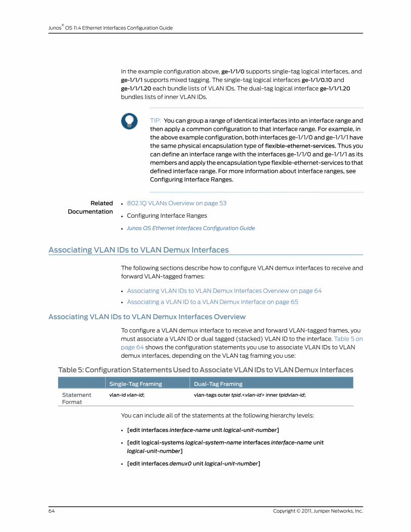
In the example configuration above, ge-1/1/0 supports single-tag logical interfaces, and
ge-1/1/1 supports mixed tagging. The single-tag logical interfaces ge-1/1/0.10 and
ge-1/1/1.20 each bundle lists of VLAN IDs. The dual-tag logical interface ge-1/1/1.20
bundles lists of inner VLAN IDs.
TIP: You can group a range of identical interfaces into an interface range andthen apply a common configuration to that interface range. For example, inthe above example configuration, both interfaces ge-1/1/0 and ge-1/1/1 havethe same physical encapsulation type of flexible-ethernet-services. Thus you
can define an interface range with the interfaces ge-1/1/0 and ge-1/1/1 as itsmembersandapply theencapsulation type flexible-ethernet-services to thatdefined interface range. For more information about interface ranges, seeConfiguring Interface Ranges.
RelatedDocumentation
802.1Q VLANs Overview on page 53•
• Configuring Interface Ranges
• Junos OS Ethernet Interfaces Configuration Guide
Associating VLAN IDs to VLANDemux Interfaces
The following sections describe how to configure VLAN demux interfaces to receive and
forward VLAN-tagged frames:
• Associating VLAN IDs to VLAN Demux Interfaces Overview on page 64
• Associating a VLAN ID to a VLAN Demux Interface on page 65
Associating VLAN IDs to VLANDemux Interfaces Overview
To configure a VLAN demux interface to receive and forward VLAN-tagged frames, you
must associate a VLAN ID or dual tagged (stacked) VLAN ID to the interface. Table 5 on
page 64 shows the configuration statements you use to associate VLAN IDs to VLAN
demux interfaces, depending on the VLAN tag framing you use:
Table5:ConfigurationStatementsUsedtoAssociateVLANIDstoVLANDemux Interfaces
Dual-Tag FramingSingle-Tag Framing
vlan-tags outer tpid.<vlan-id> inner tpidvlan-id;vlan-id vlan-id;StatementFormat
You can include all of the statements at the following hierarchy levels:
• [edit interfaces interface-name unit logical-unit-number]
• [edit logical-systems logical-system-name interfaces interface-name unit
logical-unit-number]
• [edit interfaces demux0 unit logical-unit-number]
Copyright © 2011, Juniper Networks, Inc.64
Junos®
OS 11.4 Ethernet Interfaces Configuration Guide
Associating a VLAN ID to a VLANDemux Interface
A VLAN demux interface that you have associated to a particular VLAN ID receives and
forwards incoming frames that contain a matching VLAN ID. You can associate a VLAN
ID to a single-tag logical interface or to a dual-tagged (stacked) logical interface.
1. Associating a VLAN ID to a Single-Tag VLAN Demux Interface on page 65
2. Associating a VLAN ID to a Dual-Tag VLAN Demux Interface on page 65
Associating a VLAN ID to a Single-Tag VLANDemux Interface
To associate a VLAN ID to a single-tag VLAN demux interface, include the vlan-id
statement at the [edit interfaces demux0 unit logical-unit-number] hierarchy level:
vlan-id vlan-id;
To configure an interface to support single-tag logical interfaces, you must also include
the vlan-tagging statement at the [edit interfaces interface-name] hierarchy level. To
support mixed tagging, include the flexible-vlan-tagging statement instead.
Associating a VLAN ID to a Dual-Tag VLANDemux Interface
To associate a VLAN ID to a dual-tag VLAN demux interface, include the vlan-tags
statement at the [edit interfaces demux0 unit logical-unit-number] hierarchy level:
vlan-tags inner <tpid.>vlan-id outer <tpid.>vlan-id;
To configure an interface to support dual-tag logical interfaces, include the
stacked-vlan-tagging statement at the [edit interfaces interface-name] hierarchy level.
To support mixed tagging, include the flexible-vlan-tagging statement instead.
Configuring VLAN Encapsulation
Gigabit Ethernet IQ, Gigabit Ethernet PICs with small form-factor pluggable optics (SFPs),
and MX Series router Gigabit Ethernet, Tri-Rate Ethernet copper, and 10-Gigabit Ethernet
interfaces with VLAN tagging enabled can use flexible Ethernet services, VLAN CCC, or
VLAN virtual private LAN service (VPLS) encapsulation.
Aggregated Ethernet interfaces configured for VPLS can use Ethernet VPLS or VLAN
VPLS.
To configure the encapsulation on a Gigabit Ethernet IQ or Gigabit Ethernet physical
interface, include the encapsulation statement at the [edit interfaces interface-name]
hierarchy level, specifying flexible-ethernet-services, vlan-ccc, or vlan-vpls:
[edit interfaces interface-name]encapsulation (flexible-ethernet-services | vlan-ccc | vlan-vpls);
To configure the encapsulation on an aggregated Ethernet interface, include the
encapsulation statement at the [edit interfaces interface-name]hierarchy level, specifying
flexible-ethernet-services, ethernet-vpls, or vlan-vpls:
[edit interfaces interface-name]encapsulation (flexible-ethernet-services | ethernet-vpls | vlan-vpls);
65Copyright © 2011, Juniper Networks, Inc.
Chapter 3: Configuring 802.1Q VLANs

Ethernet interfaces in VLAN mode can have multiple logical interfaces. In CCC and VPLS
modes, VLAN IDs from 1 through 511 are reserved for normal VLANs, and VLAN IDs
512 through 4094 are reserved for CCC or VPLS VLANs. For 4-port Fast Ethernet interfaces,
you can use VLAN IDs 512 through 1024 for CCC or VPLS VLANs.
For encapsulation type flexible-ethernet-services, all VLAN IDs are valid.
In general, you configure an interface’s encapsulation at the [edit interfaces
interface-name]hierarchy level. However, for some encapsulation types, including flexible
Ethernet services, Ethernet VLAN CCC and VLAN VPLS, you can also configure the
encapsulation type that is used inside the VLAN circuit itself. To do this, include the
encapsulation statement:
encapsulation (vlan-ccc | vlan-tcc | vlan-vpls);
You can include this statement at the following hierarchy levels:
• [edit interfaces interface-name unit logical-unit-number]
• [edit logical-systems logical-system-name interfaces interface-name unit
logical-unit-number]
You cannot configure a logical interface with VLAN CCC or VLAN VPLS encapsulation
unless you also configure the physical device with the same encapsulation or with flexible
Ethernet services encapsulation. In general, the logical interface must have a VLAN ID of
512 or higher; if the VLAN ID is 511 or lower, it will be subject to the normal destination
filter lookups in addition to source address filtering. However if you configure flexible
Ethernet services encapsulation, this VLAN ID restriction is removed.
Example: Configuring VLAN Encapsulation on a Gigabit Ethernet Interface
Configure VLAN CCC encapsulation on a Gigabit Ethernet interface:
interfaces ge-2/1/0 {vlan-tagging;encapsulation vlan-ccc;unit 0 {encapsulation vlan-ccc;vlan-id 600;
}}
Example: Configuring VLAN Encapsulation on an Aggregated Ethernet Interface
Configure VLAN CCC encapsulation on an aggregated Gigabit Ethernet interface:
interfaces ae0 {vlan-tagging;encapsulation vlan-vpls;unit 0 {vlan-id 100;
}}
Copyright © 2011, Juniper Networks, Inc.66
Junos®
OS 11.4 Ethernet Interfaces Configuration Guide

RelatedDocumentation
802.1Q VLANs Overview on page 53•
• Junos OS Ethernet Interfaces Configuration Guide
Configuring Extended VLAN Encapsulation
Gigabit Ethernet, 4-port Fast Ethernet, MX Series router Gigabit Ethernet, Tri-Rate Ethernet
copper, 10-Gigabit Ethernet, and aggregated Ethernet interfaces with VLAN tagging
enabled can use extended VLAN CCC or VLAN VPLS, which allow 802.1Q tagging. To
configure the encapsulation on a physical interface, include the encapsulation statement
at the [edit interfaces interface-name] hierarchy level, specifying extended-vlan-ccc or
extended-vlan-vpls:
[edit interfaces interface-name]encapsulation (extended-vlan-ccc | extended-vlan-vpls);
For extended VLAN CCC and extended VLAN VPLS encapsulation, all VLAN IDs 1 and
higher are valid. VLAN ID 0 is reserved for tagging the priority of frames.
NOTE: ForextendedVLANCCC, theVLANIDson ingressandegress interfacesmust be the same. For back-to-back connections, all VLAN IDsmust be thesame.
Example: Configuring Extended VLAN Encapsulation on a Gigabit Ethernet Interface
Configure extended VLAN CCC encapsulation on Gigabit Ethernet ingress and egress
interfaces:
interfaces ge-0/0/0 {vlan-tagging;encapsulation extended-vlan-ccc;unit 0 {vlan-id 2;family ccc;
}}interfaces ge-1/0/0 {vlan-tagging;encapsulation extended-vlan-ccc;unit 0 {vlan-id 2;family ccc;
}}
Example: Configuring Extended VLAN Encapsulation on an Aggregated Ethernet Interface
Configure extended VLAN VPLS encapsulation on an aggregated Ethernet interface:
interfaces ae0 {vlan-tagging;encapsulation extended-vlan-vpls;
67Copyright © 2011, Juniper Networks, Inc.
Chapter 3: Configuring 802.1Q VLANs

unit 0 {vlan-id 100;
}}
RelatedDocumentation
802.1Q VLANs Overview on page 53•
• Junos OS Ethernet Interfaces Configuration Guide
GuidelinesforConfiguringVLANIDList-BundledLogical InterfacesThatConnectCCCs
For MX Series routers, you can bind a list of VLAN IDs to a logical interface, configure a
Layer 2 VPN routing instance or Layer 2 circuit on the logical interface, and then use the
logical interface to configure a circuit cross-connect (CCC) to another Layer 2 VPN routing
instance or Layer 2 circuit.
A CCC allows you to configure transparent connections between two circuits so that
packets from the source circuit are delivered to the destination circuit with, at most, the
Layer 2 address being changed. You configure a CCC by connecting circuit interfaces of
the same type. For more information, see Circuit and Translational Cross-Connects
Overview.
NOTE: The Junos OS supports binding of Ethernet logical interfaces to listsof VLAN IDs onMX Series routers only. For all other routers, you can bind anEthernet logical interface toonlyasingleVLAN IDor toasingle rangeofVLANIDs.
The following configuration guidelines apply to bundling lists of VLAN IDs to Ethernet
logical interfaces used to configure CCCs:
• Guidelines for Configuring Physical Link-Layer Encapsulation to Support
CCCs on page 68
• Guidelines for Configuring Logical Link-Layer Encapsulation to Support CCCs on page 69
Guidelines for Configuring Physical Link-Layer Encapsulation to Support CCCs
To enable a physical interface to support VLAN-bundled logical interfaces that you willuse to configure a CCC, you must specify one of the following physical link-layerencapsulation types as the value of the encapsulation statement at the [edit interfacesinterface-name] hierarchy level:
[edit interfaces interface-name]encapsulation (extended-vlan-ccc | flexible-ethernet-services);
• extended-vlan-ccc—For Ethernet interfaces with standard TPID tagging.
• flexible-ethernet-services—For supported Gigabit Ethernet interfaces for which you
want to configure multiple per-unit Ethernet encapsulations.
For more information about configuring the encapsulation on a physical interface, see
Configuring Interface Encapsulation on Physical Interfaces.
Copyright © 2011, Juniper Networks, Inc.68
Junos®
OS 11.4 Ethernet Interfaces Configuration Guide
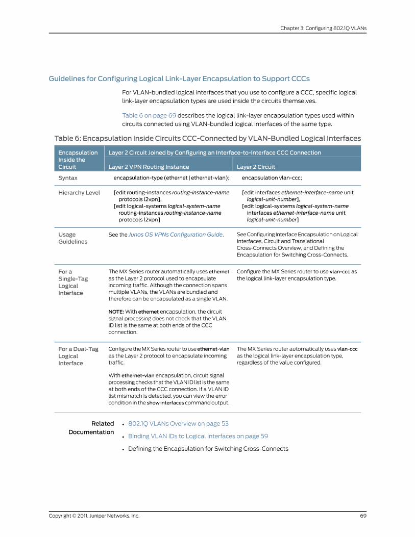
Guidelines for Configuring Logical Link-Layer Encapsulation to Support CCCs
For VLAN-bundled logical interfaces that you use to configure a CCC, specific logical
link-layer encapsulation types are used inside the circuits themselves.
Table 6 on page 69 describes the logical link-layer encapsulation types used within
circuits connected using VLAN-bundled logical interfaces of the same type.
Table 6: Encapsulation InsideCircuits CCC-Connected byVLAN-Bundled Logical Interfaces
Layer 2 Circuit Joined by Configuring an Interface-to-Interface CCC ConnectionEncapsulationInside theCircuit Layer 2 CircuitLayer 2 VPN Routing Instance
encapsulation vlan-ccc;encapsulation-type (ethernet | ethernet-vlan);Syntax
[edit interfaces ethernet-interface-name unitlogical-unit-number],
[edit logical-systems logical-system-nameinterfaces ethernet-interface-name unitlogical-unit-number]
[edit routing-instances routing-instance-nameprotocols l2vpn],
[edit logical-systems logical-system-namerouting-instances routing-instance-nameprotocols l2vpn]
Hierarchy Level
See Configuring Interface Encapsulation on LogicalInterfaces, Circuit and TranslationalCross-Connects Overview, and Defining theEncapsulation for Switching Cross-Connects.
See the Junos OS VPNs Configuration Guide.UsageGuidelines
Configure the MX Series router to use vlan-ccc asthe logical link-layer encapsulation type.
The MX Series router automatically uses ethernetas the Layer 2 protocol used to encapsulateincoming traffic. Although the connection spansmultiple VLANs, the VLANs are bundled andtherefore can be encapsulated as a single VLAN.
NOTE: With ethernet encapsulation, the circuitsignal processing does not check that the VLANID list is the same at both ends of the CCCconnection.
For aSingle-TagLogicalInterface
The MX Series router automatically uses vlan-cccas the logical link-layer encapsulation type,regardless of the value configured.
Configure the MX Series router to useethernet-vlanas the Layer 2 protocol to encapsulate incomingtraffic.
With ethernet-vlan encapsulation, circuit signalprocessing checks that the VLAN ID list is the sameat both ends of the CCC connection. If a VLAN IDlist mismatch is detected, you can view the errorcondition in the showinterfacescommand output.
For a Dual-TagLogicalInterface
RelatedDocumentation
802.1Q VLANs Overview on page 53•
• Binding VLAN IDs to Logical Interfaces on page 59
• Defining the Encapsulation for Switching Cross-Connects
69Copyright © 2011, Juniper Networks, Inc.
Chapter 3: Configuring 802.1Q VLANs

Configuring a Layer 2 VPN Routing Instance on a VLAN-Bundled Logical Interface
This topic describes how to configure a Layer 2 VPN routing instance on a logical interface
bound to a list of VLAN IDs.
• Configuring a VLAN-Bundled Logical Interface to Support a Layer 2 VPN Routing
Instance on page 70
• Specifying the Interface Over Which VPN Traffic Travels to the CE Router on page 70
• Specifying the Interface to Handle Traffic for a CCC on page 71
Configuring a VLAN-Bundled Logical Interface to Support a Layer 2 VPN Routing Instance
To configure a VLAN-bundled logical interface, specify the list of VLAN IDs by includingthe vlan-id-list statement or the vlan-tags statement on a provider edge (PE) router:
interfaces {ethernet-interface-name {vlan-tagging; # Support single- or dual-tag logical interfacesflexible-vlan-tagging; # Support mixed taggingencapsulation (extended-vlan-ccc | flexible-ethernet-services);unit logical-unit-number {vlan-id-list [vlan-id vlan-id–vlan-id]; # For single-tagvlan-tags outer <tpid.>vlan-id inner-list [vlan-id vlan-id–vlan-id]; # For dual-tag
}. . .
}}
You can include the statements at the following hierarchy levels:
• [edit]
• [edit logical-systems logical-system-name]
Specifying the Interface OverWhich VPN Traffic Travels to the CE Router
To configure a Layer 2 VPN routing instance on a PE router, include the instance-typestatement and specify the value l2vpn. To specify an interface connected to the router,include the interface statement and specify the VLAN-bundled logical interface:
instance-type l2vpn;interface logical-interface-name;
You can include the statements at the following hierarchy levels:
• [edit routing-instances routing-instance-name]
• [edit logical-systems logical-system-name routing-instances routing-instance-name]
Copyright © 2011, Juniper Networks, Inc.70
Junos®
OS 11.4 Ethernet Interfaces Configuration Guide

Specifying the Interface to Handle Traffic for a CCC
To configure the VLAN-bundled logical interface as the interface to handle traffic for acircuit connected to the Layer 2 VPN routing instance, include the following statements:
protocols {l2vpn {(control-word | no-control-word);encapsulation-type (ethernet | ethernet-vlan);site site-name {site-identifier identifier;interface logical-interface-name { # VLAN-bundled logical interface. . . interface-options . . .
}}
}}
You can include the statements at the same hierarchy level at which you include the
instance-type l2vpn and interface logical-interface-name statements:
• [edit routing-instances routing-instance-name]
• [edit logical-systems logical-system-name routing-instances routing-instance-name]
To enable a Layer 2 VPN routing instance on a PE router, include the l2vpn statement.
For more information, see the Junos OS VPNs Configuration Guide.
The encapsulation-type statement specifies the Layer 2 protocol used for traffic from
the customer edge (CE) router. If the Layer 2 VPN routing instance is being connected
to a single-tag Layer 2 circuit, specify ethernet as the encapsulation type. If the Layer 2
VPN routing instance is being connected to a dual-tag Layer 2 circuit, specifyethernet-vlan
as the encapsulation type.
To specify the interface to handle traffic for a circuit connected to the Layer 2 VPN routing
instance, include the interface statement and specify the VLAN-bundled logical interface.
Configuring a Layer 2 Circuit on a VLAN-Bundled Logical Interface
This topic describes how to configure a Layer 2 circuit on a logical interface bound to a
list of VLAN IDs.
• Configuring a VLAN-Bundled Logical Interface to Support a Layer 2 VPN Routing
Instance on page 71
• Specifying the Interface to Handle Traffic for a CCC Connected to the Layer 2
Circuit on page 72
Configuring a VLAN-Bundled Logical Interface to Support a Layer 2 VPN Routing Instance
To configure a VLAN-bundled logical interface, specify the list of VLAN IDs by includingthe vlan-id-list statement or the vlan-tags statement:
interfaces {ethernet-interface-name {
71Copyright © 2011, Juniper Networks, Inc.
Chapter 3: Configuring 802.1Q VLANs

vlan-tagging; # Support single- or dual-tag logical interfacesflexible-vlan-tagging; # Support mixed taggingencapsulation (extended-vlan-ccc | flexible-ethernet-services);unit logical-unit-number {encapsulation vlan–ccc; # Required for single-tagvlan-id-list [vlan-id vlan-id–vlan-id]; # For single-tagvlan-tags outer tpid.vlan-id inner-list [vlan-id vlan-id–vlan-id]; # For dual-tag
}. . .
}}
You can include the statements at the following hierarchy levels:
• [edit]
• [edit logical-systems logical-system-name]
For a single-tag logical interface, include theencapsulation statement and specifyvlan-ccc
so that CCC circuit encapsulation is used inside the Layer 2 circuit.
NOTE: In the case of a dual-tag logical interface, the JunosOSautomaticallyuses the vlan-ccc encapsulation type.
Specifying the Interface to Handle Traffic for a CCC Connected to the Layer 2 Circuit
To configure the VLAN-bundled logical interface as the interface to handle traffic for acircuit connected to the Layer 2 circuit, include the following statements:
l2circuit {neighbor address {interface logical-interface-name {virtual-circuit-id number;no-control-word;
}}
}
You can include the statements at the following hierarchy levels:
• [edit protocols]
• [edit logical-systems logical-system-name protocols]
To enable a Layer 2 circuit, include the l2circuit statement.
To configure the router as a neighbor for a Layer 2 circuit, specify the neighbor address
using the neighbor statement.
To specify the interface to handle traffic for a circuit connected to the Layer 2 circuit,
include the interface statement and specify the VLAN-bundled logical interface.
Copyright © 2011, Juniper Networks, Inc.72
Junos®
OS 11.4 Ethernet Interfaces Configuration Guide
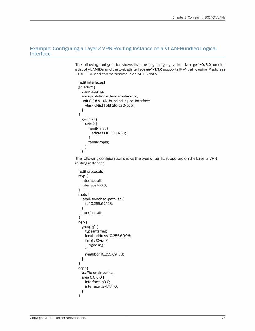
Example: Configuring a Layer 2 VPN Routing Instance on a VLAN-Bundled LogicalInterface
The following configuration shows that the single-tag logical interfacege-1/0/5.0bundlesa list of VLAN IDs, and the logical interfacege-1/1/1.0 supports IPv4 traffic using IP address10.30.1.130 and can participate in an MPLS path.
[edit interfaces]ge-1/0/5 {vlan-tagging;encapsulation extended-vlan-ccc;unit 0 { # VLAN-bundled logical interfacevlan-id-list [513 516 520-525];
}}ge-1/1/1 {unit 0 {family inet {address 10.30.1.1/30;
}family mpls;
}}
The following configuration shows the type of traffic supported on the Layer 2 VPNrouting instance:
[edit protocols]rsvp {interface all;interface lo0.0;
}mpls {label-switched-path lsp {to 10.255.69.128;
}interface all;
}bgp {group g1 {type internal;local-address 10.255.69.96;family l2vpn {signaling;
}neighbor 10.255.69.128;
}}ospf {traffic-engineering;area 0.0.0.0 {interface lo0.0;interface ge-1/1/1.0;
}}
73Copyright © 2011, Juniper Networks, Inc.
Chapter 3: Configuring 802.1Q VLANs
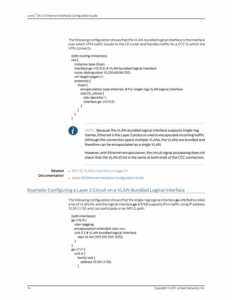
The following configuration shows that the VLAN-bundled logical interface is the interfaceover which VPN traffic travels to the CE router and handles traffic for a CCC to which theVPN connects.
[edit routing-instances]red {instance-type l2vpn;interface ge-1/0/5.0; # VLAN-bundled logical interfaceroute-distinguisher 10.255.69.96:100;vrf-target target:1:1;protocols {l2vpn {encapsulation-type ethernet; # For single-tag VLAN logical interfacesite CE_ultima {site-identifier 1;interface ge-1/0/5.0;
}}
}}
NOTE: Because the VLAN-bundled logical interface supports single-tagframes, Ethernet is theLayer 2protocol used toencapsulate incoming traffic.Although the connection spansmultiple VLANs, the VLANs are bundled andtherefore can be encapsulated as a single VLAN.
However, with Ethernet encapsulation, the circuit signal processing does notcheck that the VLAN ID list is the same at both ends of the CCC connection.
RelatedDocumentation
802.1Q VLANs Overview on page 53•
• Junos OS Ethernet Interfaces Configuration Guide
Example: Configuring a Layer 2 Circuit on a VLAN-Bundled Logical Interface
The following configuration shows that the single-tag logical interfacege-1/0/5.0bundlesa list of VLAN IDs, and the logical interfacege-1/1/1.0 supports IPv4 traffic using IP address10.30.1.1/30 and can participate in an MPLS path.
[edit interfaces]ge-1/0/5 {vlan-tagging;encapsulation extended-vlan-ccc;unit 0 { # VLAN-bundled logical interfacevlan-id-list [513 516 520-525];
}}ge-1/1/1 {unit 0 {family inet {address 10.30.1.1/30;
}
Copyright © 2011, Juniper Networks, Inc.74
Junos®
OS 11.4 Ethernet Interfaces Configuration Guide
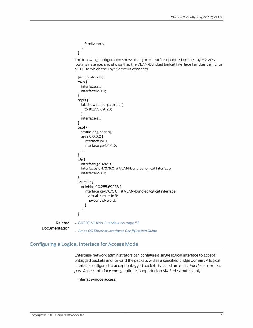
family mpls;}
}
The following configuration shows the type of traffic supported on the Layer 2 VPNrouting instance, and shows that the VLAN-bundled logical interface handles traffic fora CCC to which the Layer 2 circuit connects:
[edit protocols]rsvp {interface all;interface lo0.0;
}mpls {label-switched-path lsp {to 10.255.69.128;
}interface all;
}ospf {traffic-engineering;area 0.0.0.0 {interface lo0.0;interface ge-1/1/1.0;
}}ldp {interface ge-1/1/1.0;interface ge-1/0/5.0; # VLAN-bundled logical interfaceinterface lo0.0;
}l2circuit {neighbor 10.255.69.128 {interface ge-1/0/5.0 { # VLAN-bundled logical interfacevirtual-circuit-id 3;no-control-word;
}}
}
RelatedDocumentation
802.1Q VLANs Overview on page 53•
• Junos OS Ethernet Interfaces Configuration Guide
Configuring a Logical Interface for AccessMode
Enterprise network administrators can configure a single logical interface to accept
untagged packets and forward the packets within a specified bridge domain. A logical
interface configured to accept untagged packets is called an access interface or access
port. Access interface configuration is supported on MX Series routers only.
interface-mode access;
75Copyright © 2011, Juniper Networks, Inc.
Chapter 3: Configuring 802.1Q VLANs

You can include this statement at the following hierarchy levels:
• [edit interfaces interface-name unit logical-unit-number family bridge]
• [edit logical-systems logical-system-name interfaces interface-name unit
logical-unit-number family bridge]
When an untagged or tagged packet is received on an access interface, the packet is
accepted, the VLAN ID is added to the packet, and the packet is forwarded within the
bridge domain that is configured with the matching VLAN ID.
Example: Configuring a Logical Interface for AccessMode
The following example configures a logical interface as an access port with a VLAN ID
of 20:
[edit interfaces ge-1/2/0]unit 1 {family bridge {interface-mode access;vlan-id 20;
}}
RelatedDocumentation
802.1Q VLANs Overview on page 53•
• Junos OS Ethernet Interfaces Configuration Guide
Configuring a Logical Interface for TrunkMode
As an alternative to configuring a logical interface for each VLAN, enterprise network
administrators can configure a single logical interface to accept untagged packets or
packets tagged with any VLAN ID specified in a list of VLAN IDs. Using a VLAN ID list
conserves switch resources and simplifies configuration. A logical interface configured
to accept packets tagged with any VLAN ID specified in a list is called a trunk interface
or trunk port. Trunk interface configuration is supported on MX Series routers only. Trunk
interfaces support integrated routing and bridging (IRB).
To configure a logical interface to accept any packet tagged with a VLAN ID that matches
the list of VLAN IDs, include the interface-mode statement and specify the trunk option:
interface-mode trunk;
You can include this statement at the following hierarchy levels:
• [edit interfaces interface-name unit logical-unit-number family bridge]
• [edit logical-systems logical-system-name interfaces interface-name unit
logical-unit-number family bridge]
RelatedDocumentation
802.1Q VLANs Overview on page 53•
• Junos OS Ethernet Interfaces Configuration Guide
Copyright © 2011, Juniper Networks, Inc.76
Junos®
OS 11.4 Ethernet Interfaces Configuration Guide

Configuring the VLAN ID List for a Trunk Interface
To configure the list of VLAN IDs to be accepted by the trunk port, include the vlan-id-list
statement and specify the list of VLAN IDs. You can specify individual VLAN IDs with a
space separating the ID numbers, specify a range of VLAN IDs with a dash separating
the ID numbers, or specify a combination of individual VLAN IDs and a range of VLAN
IDs.
vlan-id-list [number number-number];
You can include this statement at the following hierarchy levels:
• [edit interfaces interface-name unit logical-unit-number family bridge interface-mode
trunk]
• [edit logical-systems logical-system-name interfaces interface-name unit
logical-unit-number family bridge interface-mode trunk]
When a packet is received that is tagged with a VLAN ID specified in the trunk interface
list of VLAN IDs, the packet is accepted and forwarded within the bridge domain that is
configured with the matching VLAN ID.
When a packet is received that is tagged with a VLAN ID not specified in the trunk interface
list of VLAN IDs, the native VLAN ID is pushed in front of the existing VLAN tag or tags
and the packet is forwarded within the bridge domain that is configured with the matching
VLAN ID.
When an untagged packet is received on a trunk interface, the native VLAN ID is added
to the packet and the packet is forwarded within the bridge domain that is configured
with the matching VLAN ID.
A bridge domain configured with a matching VLAN ID must be configured before the
trunk interface is configured. To learn more about configuring bridge domains, see the
Junos Routing Protocols Configuration Guide.
RelatedDocumentation
802.1Q VLANs Overview on page 53•
• Junos OS Ethernet Interfaces Configuration Guide
Configuring a Trunk Interface on a Bridge Network
On MX Series routers, you can configure a trunk interface on a bridge network.
The following output sample shows trunk port configuration on a bridge network:
user@host# run show interfacesge-0/0/0 { flexible-vlan-tagging; encapsulation flexible-ethernet-services; unit 0 { encapsulation vlan-bridge; vlan-id 1; }
77Copyright © 2011, Juniper Networks, Inc.
Chapter 3: Configuring 802.1Q VLANs
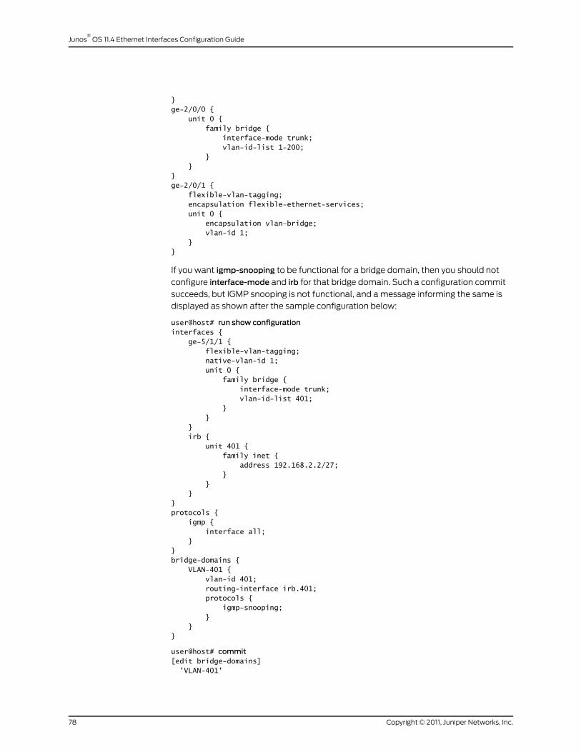
}ge-2/0/0 { unit 0 { family bridge { interface-mode trunk; vlan-id-list 1-200; } }}ge-2/0/1 { flexible-vlan-tagging; encapsulation flexible-ethernet-services; unit 0 { encapsulation vlan-bridge; vlan-id 1; }}
If you want igmp-snooping to be functional for a bridge domain, then you should not
configure interface-mode and irb for that bridge domain. Such a configuration commit
succeeds, but IGMP snooping is not functional, and a message informing the same is
displayed as shown after the sample configuration below:
user@host# run show configurationinterfaces { ge-5/1/1 { flexible-vlan-tagging; native-vlan-id 1; unit 0 { family bridge { interface-mode trunk; vlan-id-list 401; } } } irb { unit 401 { family inet { address 192.168.2.2/27; } } }}protocols { igmp { interface all; }}bridge-domains { VLAN-401 { vlan-id 401; routing-interface irb.401; protocols { igmp-snooping; } }}
user@host# commit[edit bridge-domains] 'VLAN-401'
Copyright © 2011, Juniper Networks, Inc.78
Junos®
OS 11.4 Ethernet Interfaces Configuration Guide

IGMP Snooping not supported with IRB and trunk mode interface ge-5/1/1.0commit complete
To achieve IGMP snooping for a bridge domain, you should use such a configuration as
shown in the following example:
user@host# run show configurationinterfaces { ge-0/0/1 { flexible-vlan-tagging; native-vlan-id 1; encapsulation flexible-ethernet-services; unit 0 { encapsulation vlan-bridge; vlan-id 401; } } irb { unit 401 { family inet { address 192.168.2.2/27; } } }}protocols { igmp { interface all; }}bridge-domains { VLAN-401 { vlan-id 401; interface ge-0/0/1.0; routing-interface irb.401; protocols { igmp-snooping; } }}
user@host# commitcommit complete
RelatedDocumentation
• 802.1Q VLANs Overview on page 53
• interface-mode
• Junos OS Ethernet Interfaces Configuration Guide
79Copyright © 2011, Juniper Networks, Inc.
Chapter 3: Configuring 802.1Q VLANs

Copyright © 2011, Juniper Networks, Inc.80
Junos®
OS 11.4 Ethernet Interfaces Configuration Guide
CHAPTER 4
Configuring Aggregated EthernetInterfaces
• Aggregated Ethernet Interfaces Overview on page 81
• Configuring an Aggregated Ethernet Interface on page 83
• Deleting an Aggregated Ethernet Interface on page 84
• Configuring Multichassis Link Aggregation on page 85
• Active-Active Bridging and VRRP over IRB Functionality on MX Series Routers
Overview on page 86
• Configuring Active-Active Bridging and VRRP over IRB in Multichassis Link Aggregation
on MX Series Routers on page 95
• IGMP Snooping in MC-LAG Active-Active on MX Series Routers Overview on page 100
• Configuring IGMP Snooping in MC-LAG Active-Active on MX Series Routers on page 106
• Configuring Aggregated Ethernet Link Protection on page 107
• Configuring the Number of Aggregated Ethernet Interfaces on the Device on page 109
• Configuring Aggregated Ethernet LACP on page 109
• Configuring Untagged Aggregated Ethernet Interfaces on page 115
• Configuring Aggregated Ethernet Link Speed on page 117
• Configuring Aggregated Ethernet Minimum Links on page 117
• Configuring Multicast Statistics Collection on Aggregated Ethernet Interfaces on page 118
• Configuring Scheduler on Aggregated Ethernet Interfaces Without Link
Protection on page 119
• Configuring Symmetrical Load Balancing on an 802.3ad Link Aggregation Group on
MX Series Routers on page 120
Aggregated Ethernet Interfaces Overview
Link aggregation of Ethernet interfaces is defined in the IEEE 802.3ad standard. The
Junos implementation of 802.3ad balances traffic across the member links within an
aggregated Ethernet bundle based on the Layer 3 information carried in the packet. This
implementation uses the same load-balancing algorithm used for per-packet load
balancing. For information about per-packet load balancing, see the Junos OS Routing
Protocols Configuration Guide.
81Copyright © 2011, Juniper Networks, Inc.

NOTE: For information about configuring circuit cross-connects overaggregatedEthernet, seeCircuit andTranslationalCross-ConnectsOverview.
Platform Support for Aggregated Ethernet Interfaces
You configure an aggregated Ethernet virtual link by specifying the link number as a
physical device and then associating a set of ports that have the same speed and are in
full-duplex mode. The physical interfaces can be Fast Ethernet, Tri-Rate Ethernet copper,
Gigabit Ethernet, Gigabit Ethernet IQ, 10-Gigabit Ethernet IQ, Gigabit Ethernet IQ2 and
IQ2-E, or 10-Gigabit Ethernet IQ2 and IQ2-E. Generally, you cannot use a combination of
these interfaces within the same aggregated link; however, you can combine Gigabit
Ethernet and Gigabit Ethernet IQ interfaces in a single aggregated Ethernet bundle.
The following routers support a maximum of 16 physical interfaces per single aggregated
Ethernet bundle:
• M120
• M320
• All MX Series 3D Universal Edge Routers
• All T Series routers
All other routers support a maximum of 8 physical interfaces per aggregated Ethernet
bundle.
Aggregated Ethernet interfaces can use interfaces from different FPCs, DPCs, PICs, or
Trio MPCs.
Configuration Guidelines for Aggregated Ethernet Interfaces
Simple filters are not supported for interfaces in aggregated Ethernet bundles:
• in M Series routers, simple filters are supported in Gigabit Ethernet Enhanced Intelligent
Queuing interfaces only, except when the interface is part of an aggregated Ethernet
bundle.
• in MX Series routers, simple filters are supported in Enhanced Queuing Dense Port
Concentrator (EQ DPC) interfaces only, except when the interface is part of an
aggregated Ethernet bundle.
For more information about simple filters, see the Junos OS Class of Service Configuration
Guide.
On the aggregated bundle, no IQ-specific capabilities such as MAC accounting, VLAN
rewrites, and VLAN queuing are available. For more information about IQ-specific
capabilities, see “Gigabit Ethernet Accounting and Policing Overview” on page 311.
Use the show interfaces aggregate-interface extensive and show interfaces
aggregate.logical-interface commands to show the bandwidth of the aggregate. Also, the
Copyright © 2011, Juniper Networks, Inc.82
Junos®
OS 11.4 Ethernet Interfaces Configuration Guide

SNMP object identifierifSpeed/ifHighSpeed shows the corresponding bandwidth on the
aggregate logical interface if it is configured properly.
Aggregated Ethernet interfaces can be either tagged or untagged, with LACP enabled or
disabled. Aggregated Ethernet interfaces on MX Series routers support the configuration
of flexible-vlan-tagging, native-vlan-id, and on dual-tagged frames, which consist of the
following configuration statements:
• inner-tag-protocol-id
• inner-vlan-id
• pop-pop
• pop-swap
• push-push
• swap-push
• swap-swap
In all cases, you must set the number of aggregated Ethernet interfaces on the chassis.
You can also set the link speed and the minimum links in a bundle.
RelatedDocumentation
inner-tag-protocol-id on page 457•
• inner-vlan-id on page 458
• pop-pop on page 493
• pop-swap on page 494
• push-push on page 503
• swap-push on page 512
• swap-swap on page 513
• Gigabit Ethernet Accounting and Policing Overview on page 311
• Junos OS Ethernet Interfaces Configuration Guide
Configuring an Aggregated Ethernet Interface
On Fast Ethernet, Tri-Rate Ethernet copper, Gigabit Ethernet, and 10-Gigabit Ethernet
interfaces on M Series and T Series routers, you can associate a physical interface with
an aggregated Ethernet interface.
To configure an aggregated Ethernet interface:
1. Specify that you want to configure the link aggregation group interface.
user@host# edit interfaces interface-name
2. Configure the aggregated Ethernet interface.
[edit interfaces interface-name]user@host# set (fastether-options | gigether-options) 802.3ad aex
83Copyright © 2011, Juniper Networks, Inc.
Chapter 4: Configuring Aggregated Ethernet Interfaces
You specify the interface instance number x to complete the link association; x can be
from 0 through 127, for a total of 128 aggregated interfaces on M Series and T Series
routers and can be from 1 through 480, for a total of 480 aggregated interfaces on MX
Series routers. You must also include a statement defining aex at the [edit interfaces]
hierarchy level. You can optionally specify other physical properties that apply specifically
to the aggregated Ethernet interfaces; for details, see “Ethernet Interfaces Overview” on
page 35, and for a sample configuration, see “Example: Configuring Aggregated Ethernet
Interfaces” on page 428.
NOTE: Ingeneral, aggregatedEthernetbundlessupport the featuresavailableonall supported interfaces thatcanbecomeamember linkwithin thebundle.As an exception, Gigabit Ethernet IQ features and some newer GigabitEthernet features are not supported in aggregated Ethernet bundles.
Gigabit Ethernet IQ and SFP interfaces can bemember links, but IQ- andSFP-specific features are not supported on the aggregated Ethernet bundleeven if all themember links individually support those features.
You need to configure the correct link speed for the aggregated Ethernetinterface to eliminate any warningmessage.
For information about E Series routers, see Understanding Aggregated Ethernet Interfaces
and LACP.
RelatedDocumentation
Configuring the Number of Aggregated Ethernet Interfaces on the Device on page 109•
• Deleting an Aggregated Ethernet Interface on page 84
• Aggregated Ethernet Interfaces Overview on page 81
• Junos OS Ethernet Interfaces Configuration Guide
Deleting an Aggregated Ethernet Interface
There are two approaches to deleting an aggregated Ethernet interface:
• You can delete an aggregated Ethernet interface from the interface configuration. The
Junos OS removes the configuration statements related to aex and sets this interface
to down state.
• You can also permanently remove the aggregated Ethernet interface from the device
configuration by deleting it from the device-count on the routing device.
To delete an aggregated Ethernet interface:
1. Delete the aggregated Ethernet configuration.
This step changes the interface state to down and removing the configuration
statements related to aex.
[edit]user@host# delete interfaces aex
Copyright © 2011, Juniper Networks, Inc.84
Junos®
OS 11.4 Ethernet Interfaces Configuration Guide

2. Delete the interface from the device count.
[edit]user@host# delete chassis aggregated-devices ethernet device-count
RelatedDocumentation
Configuring an Aggregated Ethernet Interface on page 83•
• Configuring the Number of Aggregated Ethernet Interfaces on the Device on page 109
• Aggregated Ethernet Interfaces Overview on page 81
• Junos OS Ethernet Interfaces Configuration Guide
ConfiguringMultichassis Link Aggregation
On MX Series routers, multichassis link aggregation (MC-LAG) enables a device to form
a logical LAG interface with two or more other devices. MC-LAG provides additional
benefits over traditional LAG in terms of node level redundancy, multi-homing support,
and loop-free Layer 2 network without running Spanning Tree Protocol (STP). MC-LAG
can be configured for VPLS routing instance, CCC application, and Layer 2 circuit
encapsulation types.
The MC-LAG devices use Inter-Chassis Control Protocol (ICCP) to exchange the control
information between two MC-LAG network devices.
On one end of MC-LAG is a MC-LAG client device that has one or more physical links in
a link aggregation group (LAG). This client device does not need to be aware of MC-LAG.
On the other side of MC-LAG are two MC-LAG network devices. Each of these network
devices has one or more physical links connected to a single client device. The network
devices coordinate with each other to ensure that data traffic is forwarded properly.
MC-LAG includes the following functionality:
• Active standby mode is supported using Link Aggregation Control Protocol (LACP)
• MC-LAG operates only between two chassis.
• Layer 2 circuit functions are supported with ether-ccc encapsulation.
• VPLS functions are supported with ether-vpls and vlan-vpls.
To enable MC-LAG, include the mc-ae statement at the [edit interfaces aeX
aggregated-ether-options]hierarchy level along with either theencapsulationethernet-ccc
or encapsulation ethernet-vpls statement at the [edit interfaces aeX] hierarchy level:
[edit interfaces aeX]encapsulation (ethernet-ccc | ethernet-vpls);aggregated-ether-options {mc-ae {chassis-id chassis-id;mc-ae-idmc-ae-id;mode (active-active | active-standby);redundancy-group group-id;status-control (active | standby);
85Copyright © 2011, Juniper Networks, Inc.
Chapter 4: Configuring Aggregated Ethernet Interfaces

}}
To delete a MC-LAG interface from the configuration, issue the delete interfaces aeX
aggregated-ether-optionsmc-ae command at the [edit] hierarchy level in configuration
mode:
[edit]user@host# delete interfaces aeX aggregated-ether-optionsmc-ae
RelatedDocumentation
Active-Active Bridging and VRRP over IRB Functionality on MX Series Routers Overview
on page 86
•
• Configuring Active-Active Bridging and VRRP over IRB in Multichassis Link Aggregation
on MX Series Routers on page 95
• show interfaces mc-ae
• Junos OS Ethernet Interfaces Configuration Guide
Active-ActiveBridgingandVRRPover IRBFunctionalityonMXSeriesRoutersOverview
MX Series routers support active-active bridging and virtual router redundancy protocol
(VRRP) over Integrated routing and bridging (IRB). This is a common scenario used in
data centers. This section provides an overview of the supported functionality.
Active-active bridging and VRRP over IRB support extends multichassis link aggregation
group (MC-LAG) by adding the following functionality:
• Interchassis link (ICL) pseudowire interface or Ethernet interface (ICL-PL field) for
active-active bridging
• Active-active bridging
• VRRP over IRB for active-active bridging
• A single bridge domain cannot correspond to two redundancy group IDs
The topologies shown in Figure 1 on page 87 and Figure 2 on page 87 are supported. These
figures use the following abbreviations:
• Aggregated Ethernet (AE)
• Interchassis link (ICL)
• Multichassis link (MCL)
Copyright © 2011, Juniper Networks, Inc.86
Junos®
OS 11.4 Ethernet Interfaces Configuration Guide
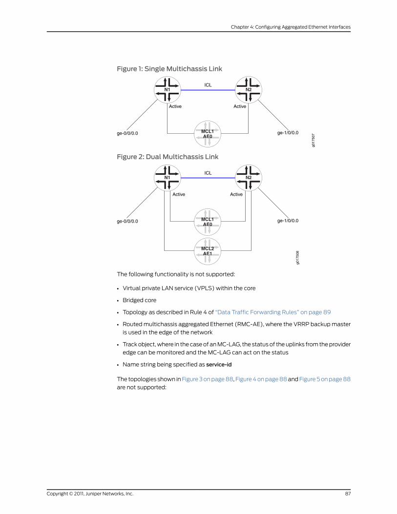
Figure 1: Single Multichassis Link
N1 N2
MCL1AE0
ge-0/0/0.0 ge-1/0/0.0
Active Active
g017
507
ICL
Figure 2: Dual Multichassis Link
N1 N2
MCL1AE0
ge-0/0/0.0 ge-1/0/0.0
Active Active
g017
508
ICL
MCL2AE1
The following functionality is not supported:
• Virtual private LAN service (VPLS) within the core
• Bridged core
• Topology as described in Rule 4 of “Data Traffic Forwarding Rules” on page 89
• Routed multichassis aggregated Ethernet (RMC-AE), where the VRRP backup master
is used in the edge of the network
• Track object, where in the case of an MC-LAG, the status of the uplinks from the provider
edge can be monitored and the MC-LAG can act on the status
• Name string being specified as service-id
The topologies shown in Figure 3 on page 88, Figure 4 on page 88 and Figure 5 on page 88
are not supported:
87Copyright © 2011, Juniper Networks, Inc.
Chapter 4: Configuring Aggregated Ethernet Interfaces
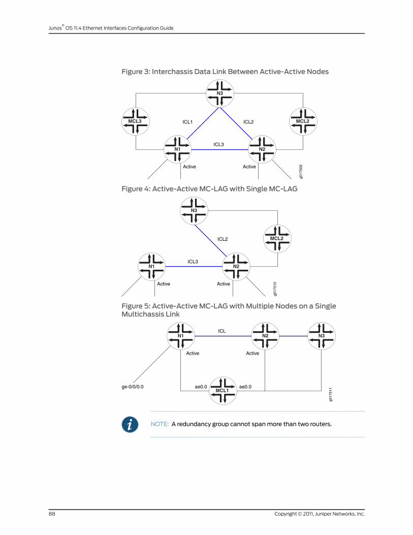
Figure 3: Interchassis Data Link Between Active-Active Nodes
N1 N2
Active Active
g017
509
ICL3
N3
ICL1 ICL2MCL3 MCL2
Figure 4: Active-Active MC-LAGwith Single MC-LAG
N1 N2
Active Active
g017
510
ICL3
N3
ICL2 MCL2
Figure 5: Active-Active MC-LAGwithMultiple Nodes on a SingleMultichassis Link
N1 N2
Active Active
g017
511
ICLN3
MCL1ge-0/0/0.0 ae0.0 ae0.0
NOTE: A redundancy group cannot spanmore than two routers.
Copyright © 2011, Juniper Networks, Inc.88
Junos®
OS 11.4 Ethernet Interfaces Configuration Guide

When configured to be active-active, the client device load balances the traffic to the
peering MC-LAG network devices. In a bridging environment, this could potentially cause
the following problems:
• Traffic received on the MC-LAG from one MC-LAG network device could be looped
back to the same MC-LAG on the other MC-LAG network device.
• Duplicated packets could be received by the MC-LAG client device.
• Traffic could be unnecessarily forwarded on the interchassis link.
To better illustrate the problems listed above, consider Figure 6 on page 89, where an
MC-LAG device MCL1 and single-homed clients ge-0/0/0.0 and ge-1/0/0.0 are allowed
to talk to each other through an ICL:
• Traffic received on network routing instance N1 from MCL1 could be flooded to ICL to
reach network routing instance N2. Once it reaches network routing instance N2, it
could be flooded back to MCL1.
• Traffic received on interface ge-0/0/0.0 could be flooded to MCL1 and ICL on network
routing instance N1. Once network routing instance N2 receives such traffic from ICL,
it could be again flooded to MCL1.
• If interface ge-1/0/0.0 does not exist on network routing instance N2, traffic received
from interface ge-0/0/0.0 or MCL1 on network routing instance N1 could be flooded
to network routing instance N2 through ICL unnecessarily since interface ge-0/0/0.0
and MCL1 could reach each other through network routing instance N1.
Figure 6: MC-LAG Device and Single-Homed Client
N1 N2
ge-0/0/0.0 ge-1/0/0.0
Active Activeg0
1751
2
ICL
ae0.0 ae0.0MCL1
Data Traffic Forwarding Rules
In active-active bridging and VRRP over IRB topographies, network interfaces are
categorized into three different interface types, as follows:
S-Links—Single-homed link (S-Link) terminating on MC-LAG-N device or MC-LAG in
active-standby mode. In Figure 6 on page 89, interfaces ge-0/0/0.0 and ge-1/0/0.0
are S-Links.
MC-Links—MC-LAG links. In Figure 6 on page 89, interface ae0.0 is the MC-Link.
ICL—Interchassis data link.
89Copyright © 2011, Juniper Networks, Inc.
Chapter 4: Configuring Aggregated Ethernet Interfaces

Based on incoming and outgoing interface types, some constraints are added to the
Layer 2 forwarding rules for MC-LAG configurations, as described in the data traffic
forwarding rules. Note that if only one of the MC-LAG member link is in the UP state, it
is considered an S-Link.
The following data traffic forwarding rules apply:
1. When an MC-LAG network receives a packet from a local MC-Link or S-Link, the packet
is forwarded to other local interfaces, including S-Links and MC-Links based on the
normal Layer 2 forwarding rules and on the configuration of the mesh-group and
no-local-switching statements. If MC-Links and S-Links are in the same mesh group
and their no-local-switching statements are enabled, the received packets are only
forwarded upstream and not sent to MC-Links and S-Links.
2.
NOTE: The functionality described in rule 2 is not supported.
The following circumstances determine whether or not an ICL receives a packet from
a local MC-Link or S-Link:
a. If the peer MC-LAG network device has S-Links or MC-LAGs that do not reside on
the local MC-LAG network device.
b. Whether or not interfaces on two peering MC-LAG network devices are allowed
to talk to each other.
Only if both a. and b. are true, is traffic always forwarded to the ICL.
3. When an MC-LAG network receives a packet from the ICL, the packet is forwarded to
all local S-Links and active MC-LAGs that do not exist in the MC-LAG network that
the packet comes from.
4.
NOTE: The topology shown in Figure 7 on page 91 is not supported.
In certain cases, for example the topology shown in Figure 7 on page 91, there could
be a loop caused by the ICL. To break the loops, one of the following mechanisms
could be used:
a. Run certain protocols, such as spanning tree protocol (STP). In this case, whether
packets received on one ICL are forwarded to other ICLs is determined by using
Rule 3.
b. Configure the ICL to be fully meshed among the MC-LAG network devices. In this
case, traffic received on the ICL would be not be forwarded to any other ICLs.
In either case, duplicate packets could be forwarded to the MC-LAG clients. Consider
the topology shown in Figure 7 on page 91, where if network routing instance N1 receives
a packet from ge-0/0/0.0, it could be flooded to ICL1 and ICL3.
When receiving from ICL1 and ICL3, network routing instances N3 and N2 could flood
the same packet to MCL2, as shown in Figure 7 on page 91. To prevent this from
Copyright © 2011, Juniper Networks, Inc.90
Junos®
OS 11.4 Ethernet Interfaces Configuration Guide

happening, the ICL designated forwarder should be elected between MC-LAG peers
and traffic received on an ICL could be forwarded to the active-active MC-LAG client
by the designated forwarder only.
Figure 7: Loop Caused by the ICL Links
N3
ICL1 ICL2MCL3 MCL2
N1 N2
ge-0/0/0.0 ge-1/0/0.0
Active Active
g017
513
ICL3
MCL1
5. When received from an ICL, traffic should not be forwarded to the core-facing client
link connection between two provider edge (PE) devices (C-Link) if the peer chassis's
(where the traffic is coming from) C-Link is UP.
MACAddress Management
If an MC-LAG is configured to be active-active, upstream and downstream traffic could
go through different MC-LAG network devices. Since the media access control address
(MAC address) is learned only on one of the MC-LAG network devices, the reverse
direction's traffic could be going through the other MC-LAG network and flooded
unnecessarily. Also, a single-homed client's MAC address is only learned on the MC-LAG
network device it is attached to. If a client attached to the peer MC-LAG network needs
to communicate with that single-homed client, then traffic would be flooded on the peer
MC-LAG network device. To avoid unnecessary flooding, whenever a MAC address is
learned on one of the MC-LAG network devices, it gets replicated to the peer MC-LAG
network device. The following conditions should be applied when MAC address replication
is performed:
• MAC addresses learned on a MC-LAG of one MC-LAG network device should be
replicated as learned on the same MC-LAG of the peer MC-LAG network device.
• MAC addresses learned on single-homed customer edge (CE) clients of one MC-LAG
network device should be replicated as learned on ICL-PL interface of the peer MC-LAG
network device.
91Copyright © 2011, Juniper Networks, Inc.
Chapter 4: Configuring Aggregated Ethernet Interfaces

• MAC addresses learned on MC-LAG VE clients of one MC-LAG network device should
be replicated as learned on the corresponding VE interface of the peer MC-LAG network
device.
• MAC address learning on an ICL is disabled from the data path. It depends on software
to install MAC addresses replicated through interchassis control protocol (ICCP).
MACAging
MAC aging support in the Junos OS extends aggregated Ethernet logic for a specified
MC-LAG. A MAC address in software is deleted until all Packet Forwarding Engines have
deleted the MAC address. In the case of an MC-LAG, a remote provider edge is treated
as a remote Packet Forwarding Engine and has a bit in the MAC data structure.
Layer 3 Routing
In general, when an MC-LAG is configured to provide Layer 3 routing functions to
downstream clients, the MC-LAG network peers should be configured to provide the
same gateway address to the downstream clients. To the upstream routers, the MC-LAG
network peers could be viewed as either equal-cost multi path (ECMP) or two routes
with different preference values.
Junos OS supports active-active MC-LAGs using VRRP over IRB. Configuration of IP
addresses on the MC-LAG members without VRRP is not supported.
To ensure that Layer 3 operates properly, instead of dropping the Layer 3 packet, the
VRRP slave attempts to perform routing functions if the packet is received on an MC-LAG.
A VRRP slave sends and responds to address resolution protocol (ARP) requests.
For ARP, the same issue exists as with Layer 2 MAC addresses. Once ARP is learned, it
must be replicated to the MC-LAG through ICCP. The peer must install an ARP route
based on the ARP information received through ICCP.
For ARP aging, ARP requests on the MC-LAG peers can be aged out independently.
Address Resolution Protocol Active-Active MC-LAG Support Methodology
Suppose one of the PE routers issues an ARP request and another PE router gets the
response and, because of the aggregated Ethernet distribution logic, the ARP resolution
is not successful. Junos OS uses ARP response packet snooping to perform active-active
multichassis link aggregation group support, providing easy synchronization without the
need to maintain any specific state.
IGMP Snooping on Active-Active MC-LAG
For multicast to work in an active-active MC-LAG scenario, the typical topology is as
shown in Figure 8 on page 93 and Figure 9 on page 94 with interested receivers over
S-links and MC-Links. Starting in Junos OS Release 11.2, support is extended for sources
connected over Layer 2 interface.
If an MC-LAG is configured to be active-active, reports from MC-LAG clients could reach
any of the MC-LAG network device peers. Therefore the IGMP snooping module needs
to replicate the states such that the Layer 2 multicast route state on both peers are the
Copyright © 2011, Juniper Networks, Inc.92
Junos®
OS 11.4 Ethernet Interfaces Configuration Guide
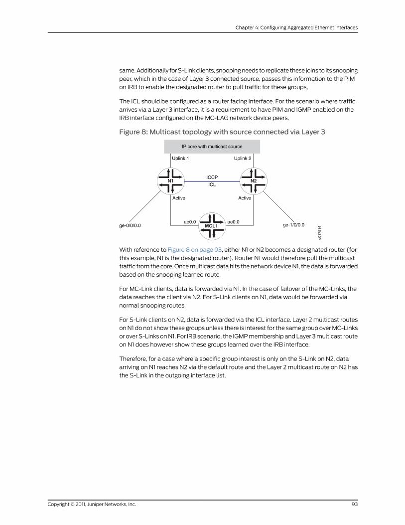
same. Additionally for S-Link clients, snooping needs to replicate these joins to its snooping
peer, which in the case of Layer 3 connected source, passes this information to the PIM
on IRB to enable the designated router to pull traffic for these groups,
The ICL should be configured as a router facing interface. For the scenario where traffic
arrives via a Layer 3 interface, it is a requirement to have PIM and IGMP enabled on the
IRB interface configured on the MC-LAG network device peers.
Figure 8: Multicast topology with source connected via Layer 3
N1 N2
ge-0/0/0.0 ge-1/0/0.0
Active Active
g017
514
ICCP
ICL
ae0.0 ae0.0MCL1
IP core with multicast source
Uplink 1 Uplink 2
With reference to Figure 8 on page 93, either N1 or N2 becomes a designated router (for
this example, N1 is the designated router). Router N1 would therefore pull the multicast
traffic from the core. Once multicast data hits the network device N1, the data is forwarded
based on the snooping learned route.
For MC-Link clients, data is forwarded via N1. In the case of failover of the MC-Links, the
data reaches the client via N2. For S-Link clients on N1, data would be forwarded via
normal snooping routes.
For S-Link clients on N2, data is forwarded via the ICL interface. Layer 2 multicast routes
on N1 do not show these groups unless there is interest for the same group over MC-Links
or over S-Links on N1. For IRB scenario, the IGMP membership and Layer 3 multicast route
on N1 does however show these groups learned over the IRB interface.
Therefore, for a case where a specific group interest is only on the S-Link on N2, data
arriving on N1 reaches N2 via the default route and the Layer 2 multicast route on N2 has
the S-Link in the outgoing interface list.
93Copyright © 2011, Juniper Networks, Inc.
Chapter 4: Configuring Aggregated Ethernet Interfaces

Figure 9: Multicast topology with source connected via MC-Link
MCL2
N1 N2
ge-0/0/0.0 ge-1/0/0.0
Active Active
g017
544
ICCP
ICL
ae0.0 ae0.0MCL1
ae1.0 ae1.0
In Figure 9 on page 94, MCL1 and MCL2 are on different devices and the multicast source
or IGMP querier is connected via MCL2. The data forwarding behavior seen is similar to
that explained for multicast topology with source connected via Layer 3.
NOTE: IGMPsnooping shouldnotbe configured inproxymode. There shouldbe no IGMP hosts or IGMP/PIM routers sitting on the ICL interface.
Up and Down Event Handling
The following conditions apply to up and down event handling:
1. If the interchassis control protocol (ICCP) connection is UP but the ICL interface
becomes DOWN, the router configured as standby will bring down all the multichassis
aggregated Ethernet interfaces shared with the peer which is connected to ICL. This
will make sure that there are no loops in the network. Otherwise, both PEs will becomes
PIM designated routers and, hence, forward multiple copies of the same packet to
the customer edge.
2. If the ICCP connection is UP and the ICL comes UP, the router configured as standby
will bring up the multichassis aggregated Ethernet interfaces shared with the peer.
3. If both the ICCP connection and the ICL are DOWN, the router configured as standby
will bring up the multichassis aggregated Ethernet interfaces shared with the peer.
4. The layer 2 address learn daemon (l2ald) does not store the information about a MAC
address learned from a peer in the kernel. If l2ald restarts, and if the MAC address was
not learned from the local multichassis aggregated Ethernet interface, l2ald will clear
the MAC addresses and this will cause the router to flood the packets destined to this
MAC address. This behavior is similar to that in a Routing Engine switchover. (Please
note that currently l2ald runs on a Routing Engine only when it is a master). Also,
during the time l2ald is DOWN, ARP packets received from an ICCP peer will be
Copyright © 2011, Juniper Networks, Inc.94
Junos®
OS 11.4 Ethernet Interfaces Configuration Guide

dropped. ARP retry will take care of this situation. This will be the case with Routing
Engine switchover too.
5. If ICCP restarts, l2ald will unremember the fact that a MAC address was learned from
a peer and, if the MAC address was learned only from the peer, that MAC address will
be deleted and the packets destined to this MAC address will be flooded.
Interchassis Control Protocol
Interchassis control protocol (ICCP) is used to sync configurations, states, and data.
ICCP supports the following types of state information:
• MC-LAG members and their operational states.
• Single-homed members and their operational states.
ICCP supports the following application database synchronization parameters:
• MAC addresses learned and to be aged.
• ARP info learned over IRB.
Interchassis Control Protocol Message
ICCP messages and attribute-value pairs (AVPs) are used for synchronizing MAC address
and ARP information.
RelatedDocumentation
Configuring Multichassis Link Aggregation on page 85•
• Configuring Active-Active Bridging and VRRP over IRB in Multichassis Link Aggregation
on MX Series Routers on page 95
• multi-chassis-protection
• peer
• show interfaces mc-ae
• Junos OS Ethernet Interfaces Configuration Guide
ConfiguringActive-ActiveBridgingandVRRPover IRB inMultichassisLinkAggregationonMX Series Routers
The following sections describe the configuration of active-active bridging and VRRP
over IRB in multichassis link aggregation (MC-LAG) on MX Series routers:
• Configuring MC-LAG on page 96
• Configuring Interchassis Link Label on page 96
• Configuring Multiple Chassis on page 97
• Configuring Service ID on page 97
• Configuring IGMP Snooping for Active-Active MC-LAG on page 99
95Copyright © 2011, Juniper Networks, Inc.
Chapter 4: Configuring Aggregated Ethernet Interfaces

ConfiguringMC-LAG
An MC-LAG is composed of logical link aggregation groups (LAGs) and is configured
under the [edit interfaces aeX] hierarchy, as follows:
[edit]interfaces {ae0 {encapsulation ethernet-bridge;multi-chassis-protection {peer 10.10.10.10 {interface ge-0/0/0;}
}aggregated-ether-options {mc-ae {mode active-active; # see note below
}}
}
NOTE: Themode active-active statement is valid only if encapsulation is
ethernet-bridge or extended-vlan-bridge.
Use the mode statement to specify if a MC-LAG is active-standby or active-active. If the
ICCP connection is UP and ICL comes UP, the router configured as standby will bring up
the multichassis aggregated Ethernet (MC-AE) interfaces shared with the peer.
Using multi-chassis-protection at the physical interface level is a way to reduce the
configuration at the logical interface level.
If the following assumption exists (follow the above example):
If there are n+1 logical interfaces under ae0, from ae0.0 through ae0.n, there will be n+1
logical interfaces under ge-0/0/0 as well, from ge-0/0/0.0 through ge-0/0/0.n, each
ge-0/0/0 logical interface will be a protection link for the ae0 logical interface.
NOTE: A bridge domain cannot haveMC-AE logical interfaces which belongto different redundancy groups.
Configuring Interchassis Link Label
Ethernet as interchassis link label (ICL-PL) (assumes interface ge-0/0/0.0 is used toprotect interface ae0.0 of MC-LAG-1):
[edit]interfaces {ae0 {....unit 0 {
Copyright © 2011, Juniper Networks, Inc.96
Junos®
OS 11.4 Ethernet Interfaces Configuration Guide

multi-chassis-protection {peer 10.10.10.10 {interface ge-0/0/0.0;
}....
}...
}}
}
The protection interface can be an Ethernet type interface like ge, xe, or an aggregated
Ethernet (ae) interface.
ConfiguringMultiple Chassis
A top-level hierarchy is used to specify multichassis-related configuration, as follows:
[edit]multi-chassis {multi-chassis-protection {peer 10.10.10.10 {interface ge-0/0/0;
}}
}
The above example specifies interface ge-0/0/0 as the multichassis protection interface
for all the multichassis aggregated Ethernet (MC-AE) interfaces which are also part of
the peer. This can be overridden by specifying protection at the physical interface level
and the logical interface level.
Configuring Service ID
You must configure the same unique network-wide configuration for a service in the set
of PE routers providing the service. You can configure the service IDs under the level of
the hierarchies shown in the following examples:
Global Configuration(default logical
system)
switch-options {service-id 10;
}bridge-domains {bd0 {service-id 2;
}}routing-instances {r1 {switch-options {service-id 10;
}bridge-domains {bd0 {service-id 2;
}}
97Copyright © 2011, Juniper Networks, Inc.
Chapter 4: Configuring Aggregated Ethernet Interfaces

}}
Logical Systems logical-system {ls1 {switch-options {service-id 10;
}}
}logical-system {ls1 {routing-instances {r1 {switch-options {service-id 10;
}}
}}
}
NOTE: Using a service name per bridge domain is not supported.
The bridge level service ID is required to link related bridge domains across peers, and
should be configured with the same value. The service-id values share the name space
across all bridging and routing instances, and across peers. Thus, duplicate values for
service IDs are not permitted across these entities.
The service ID at the bridge domain level is mandatory for type non-single VLAN bridge
domains. The service ID is optional for bridge domains with a VID defined. If no service
ID is defined in the latter case, it is picked up from the service ID configuration for that
routing instance.
NOTE: When this default routing instance (or any other routing instance)which contains abridgedomain containinganMC-AE interface is configured,youmustconfigureaglobal level switch-optionsservice-idnumber, irrespective
ofwhether thecontainedbridgedomainshavespecific service IDsconfigured.
In the example shown in Figure 10 on page 99, network routing instances N1 and N2, both
for the same service ID, are configured with same service-id in both N1 and N2. Use of a
name string instead of a number is not supported.
Copyright © 2011, Juniper Networks, Inc.98
Junos®
OS 11.4 Ethernet Interfaces Configuration Guide
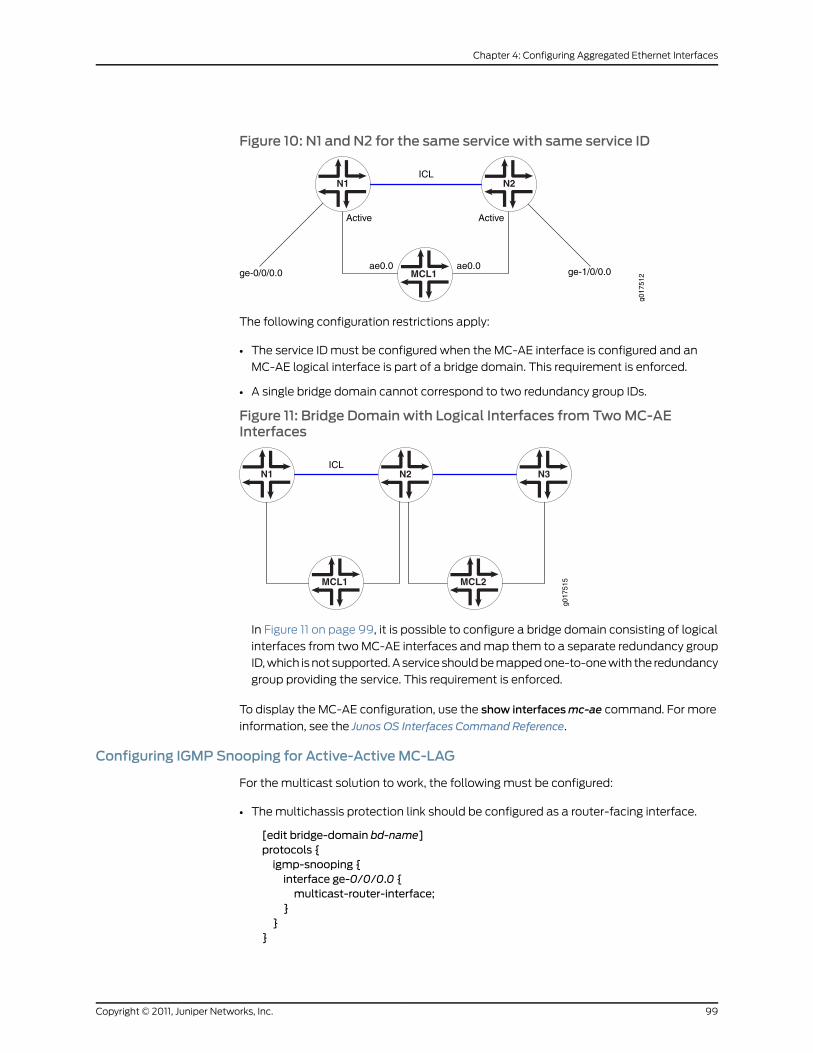
Figure 10: N1 and N2 for the same service with same service ID
N1 N2
ge-0/0/0.0 ge-1/0/0.0
Active Active
g017
512
ICL
ae0.0 ae0.0MCL1
The following configuration restrictions apply:
• The service ID must be configured when the MC-AE interface is configured and an
MC-AE logical interface is part of a bridge domain. This requirement is enforced.
• A single bridge domain cannot correspond to two redundancy group IDs.
Figure 11: Bridge Domain with Logical Interfaces from TwoMC-AEInterfaces
N1 N2
g017
515
ICLN3
MCL1 MCL2
In Figure 11 on page 99, it is possible to configure a bridge domain consisting of logical
interfaces from two MC-AE interfaces and map them to a separate redundancy group
ID, which is not supported. A service should be mapped one-to-one with the redundancy
group providing the service. This requirement is enforced.
To display the MC-AE configuration, use the show interfacesmc-ae command. For more
information, see the Junos OS Interfaces Command Reference.
Configuring IGMP Snooping for Active-Active MC-LAG
For the multicast solution to work, the following must be configured:
• The multichassis protection link should be configured as a router-facing interface.
[edit bridge-domain bd-name]protocols {igmp-snooping {interface ge-0/0/0.0 {multicast-router-interface;
}}
}
99Copyright © 2011, Juniper Networks, Inc.
Chapter 4: Configuring Aggregated Ethernet Interfaces

In this example, ge-0/0/0.0 is an ICL interface.
• The multichassis-lag-replicate-state statement options should be configured under
the multicast-snooping-options statement for that bridge domain.
NOTE: Snooping with active-active MC-LAG is only supported in non-proxymode.
RelatedDocumentation
Active-Active Bridging and VRRP over IRB Functionality on MX Series Routers Overview
on page 86
•
• Configuring Multichassis Link Aggregation on page 85
• mc-ae
• multi-chassis-protection
• peer
• show interfaces irb
• show interfaces mc-ae
• Junos OS Ethernet Interfaces Configuration Guide
IGMP Snooping in MC-LAG Active-Active onMX Series Routers Overview
• IGMP Snooping in MC-LAG Active-Active on MX Series Routers Functionality on page 100
• Typically Supported Network Topology for IGMP Snooping with MC-LAG Active-Active
Bridging on page 102
• Control plane state updates triggered by packets received on remote chassis on page 102
• Data forwarding on page 103
• Pure Layer 2 Topology Without Integrated Routing and Bridging on page 104
• Qualified Learning on page 104
• Data Forwarding with Qualified Learning on page 105
• Static Groups on Single Homed Interfaces on page 105
• Router Facing Interfaces as Multichassis Links on page 105
IGMP Snooping in MC-LAG Active-Active onMX Series Routers Functionality
MX Series routers support multichassis link aggregation group (MC-LAG) active-active
and IGMP snooping in active-standby mode. MC-LAG allows one device to form a logical
LAG interface with two or more network devices. MC-LAG provides additional benefits
including node level redundancy, multi-homing, and loop-free layer-2 network without
running STP. The following features are supported:
• State synchronization between peers for IGMP snooping in a bridge domain with only
Layer 2 interfaces
Copyright © 2011, Juniper Networks, Inc.100
Junos®
OS 11.4 Ethernet Interfaces Configuration Guide

• Qualified learning
• Router facing multichassis links
MX Series routers support the following enhancements to active-active bridging and
virtual router redundancy protocol (VRRP) over integrated routing and bridging (IRB):
• MC-LAG support for IGMP snooping in a pure Layer 2 switch
• MC-LAG support for IGMP snooping in bridge domains doing qualified learning
• Support for MC-Links being router facing interfaces
The following functions are not supported:
• MC-LAG for VPLS instances
• MC-Links trunk ports
• Proxy mode for active-active
• Adding interchassis links to outgoing interfaces on an as needed basis. Interchassis
links can be added to the outgoing interface list as router facing interfaces.
101Copyright © 2011, Juniper Networks, Inc.
Chapter 4: Configuring Aggregated Ethernet Interfaces
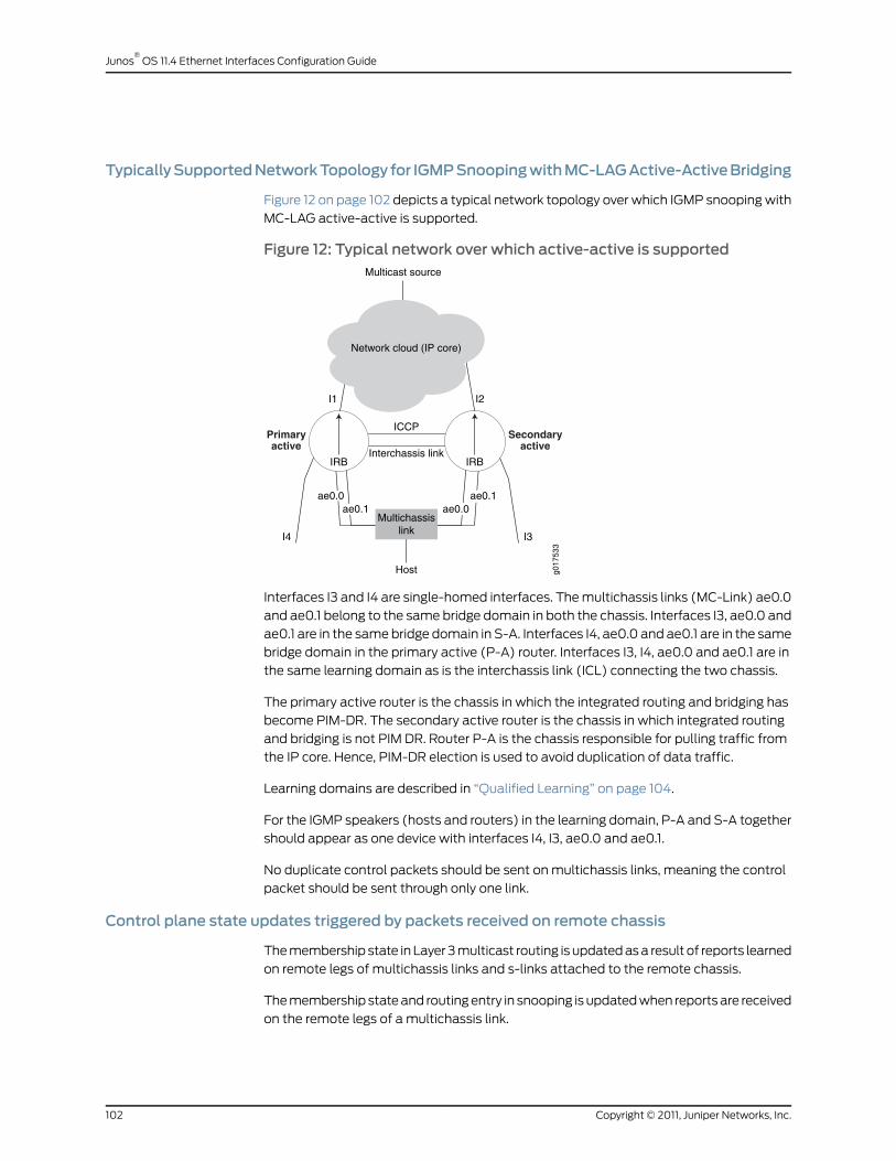
TypicallySupportedNetworkTopology for IGMPSnoopingwithMC-LAGActive-ActiveBridging
Figure 12 on page 102 depicts a typical network topology over which IGMP snooping with
MC-LAG active-active is supported.
Figure 12: Typical network over which active-active is supported
ICCP
Interchassis link
Host
Multicast source
Network cloud (IP core)
I1 I2
I3I4
Multichassislink
Primaryactive
Secondaryactive
IRB IRB
ae0.0ae0.1 ae0.0
ae0.1
g017
533
Interfaces I3 and I4 are single-homed interfaces. The multichassis links (MC-Link) ae0.0
and ae0.1 belong to the same bridge domain in both the chassis. Interfaces I3, ae0.0 and
ae0.1 are in the same bridge domain in S-A. Interfaces I4, ae0.0 and ae0.1 are in the same
bridge domain in the primary active (P-A) router. Interfaces I3, I4, ae0.0 and ae0.1 are in
the same learning domain as is the interchassis link (ICL) connecting the two chassis.
The primary active router is the chassis in which the integrated routing and bridging has
become PIM-DR. The secondary active router is the chassis in which integrated routing
and bridging is not PIM DR. Router P-A is the chassis responsible for pulling traffic from
the IP core. Hence, PIM-DR election is used to avoid duplication of data traffic.
Learning domains are described in “Qualified Learning” on page 104.
For the IGMP speakers (hosts and routers) in the learning domain, P-A and S-A together
should appear as one device with interfaces I4, I3, ae0.0 and ae0.1.
No duplicate control packets should be sent on multichassis links, meaning the control
packet should be sent through only one link.
Control plane state updates triggered by packets received on remote chassis
The membership state in Layer 3 multicast routing is updated as a result of reports learned
on remote legs of multichassis links and s-links attached to the remote chassis.
The membership state and routing entry in snooping is updated when reports are received
on the remote legs of a multichassis link.
Copyright © 2011, Juniper Networks, Inc.102
Junos®
OS 11.4 Ethernet Interfaces Configuration Guide
When reports are received on S-links attached to the remote chassis the membership
state or routing entry in snooping is not updated.
The list of <s,g>s for which the state is maintained is the same in both the chassis under
snooping as long as the outgoing interface lists involve only multichassis links.
Data forwarding
This discussion assumes integrated routing and bridging on P-A is the PIM-DR. It pulls
the traffic from sources in the core. Traffic might also come on Layer 2 interfaces in the
bridge domain. For hosts directly connected to the P-A chassis, there is no change in the
way data is delivered.
For delivering traffic to hosts connected to S-A (which is the non-DR) on the single-homed
link like I3, we rely on interchassis link. The traffic that hits P-A is sent over ICL to S-A to
be delivered to the links that have reported interests in s,g and the links that are router
facing.
When ae0 leg in P-A goes down, the hosts connected to the multichassis link will receive
traffic via ICL. In S-A, traffic received on ICL is sent to multichassis links in the outgoing
interface list for which the ae counterpart in P-A is down.
103Copyright © 2011, Juniper Networks, Inc.
Chapter 4: Configuring Aggregated Ethernet Interfaces
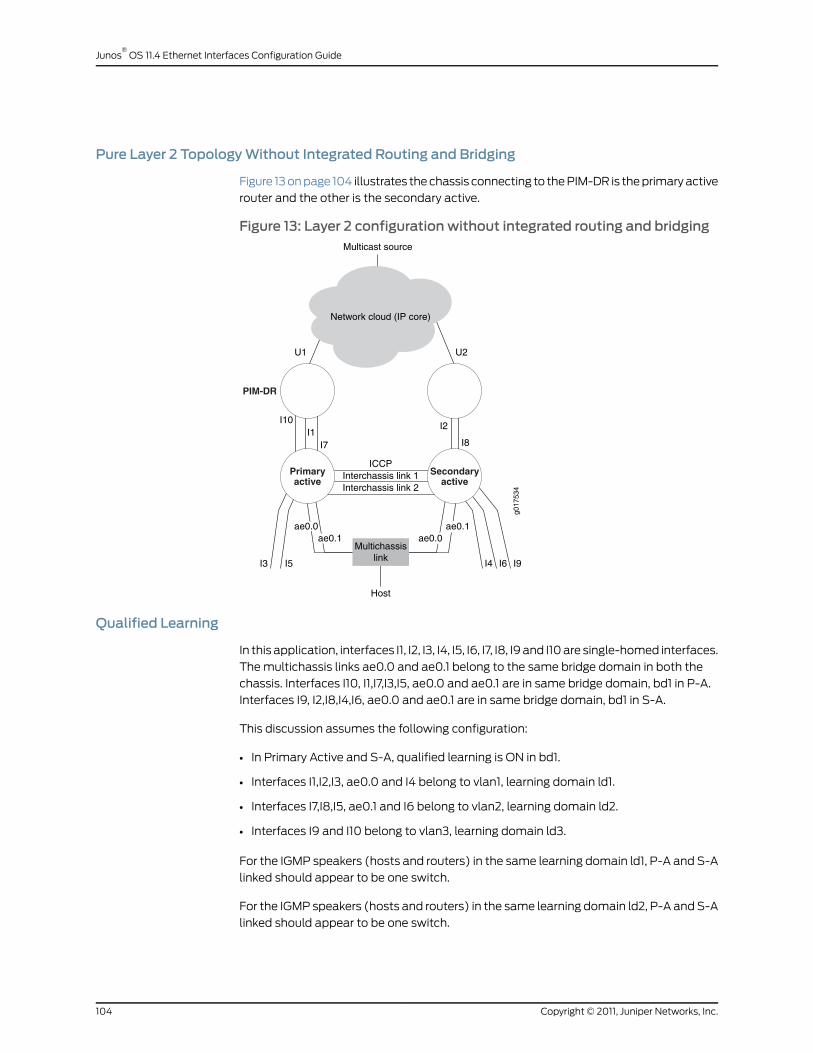
Pure Layer 2 TopologyWithout Integrated Routing and Bridging
Figure 13 on page 104 illustrates the chassis connecting to the PIM-DR is the primary active
router and the other is the secondary active.
Figure 13: Layer 2 configuration without integrated routing and bridging
I4 I6 I9I5I3
ICCPInterchassis link 1Interchassis link 2
Host
Multicast source
Network cloud (IP core)
U1 U2
Multichassislink
Primaryactive
Secondaryactive
ae0.0ae0.1 ae0.0
ae0.1g0
1753
4
PIM-DR
I10I1
I7
I2
I8
Qualified Learning
In this application, interfaces I1, I2, I3, I4, I5, I6, I7, I8, I9 and I10 are single-homed interfaces.
The multichassis links ae0.0 and ae0.1 belong to the same bridge domain in both the
chassis. Interfaces I10, I1,I7,I3,I5, ae0.0 and ae0.1 are in same bridge domain, bd1 in P-A.
Interfaces I9, I2,I8,I4,I6, ae0.0 and ae0.1 are in same bridge domain, bd1 in S-A.
This discussion assumes the following configuration:
• In Primary Active and S-A, qualified learning is ON in bd1.
• Interfaces I1,I2,I3, ae0.0 and I4 belong to vlan1, learning domain ld1.
• Interfaces I7,I8,I5, ae0.1 and I6 belong to vlan2, learning domain ld2.
• Interfaces I9 and I10 belong to vlan3, learning domain ld3.
For the IGMP speakers (hosts and routers) in the same learning domain ld1, P-A and S-A
linked should appear to be one switch.
For the IGMP speakers (hosts and routers) in the same learning domain ld2, P-A and S-A
linked should appear to be one switch.
Copyright © 2011, Juniper Networks, Inc.104
Junos®
OS 11.4 Ethernet Interfaces Configuration Guide

Since there are no multichassis links in learning domain ld3, for the IGMP speakers (hosts
and routers) in learning domain ld3, P-A and S-A will not appear to be one switch.
This discussion assumes interchassis link ICL1 corresponds to learning domain ld1 and
interchassis link ICL2 corresponds to learning domain ld2.
Control packet flow is supported, with the exception of passing information to IRB.
Data Forwarding with Qualified Learning
This discussion assumes one learning domain (LD), ld1, and further assumes interface I1
on router P-A is connected to the PIM-DR in the learning domain and pulls the traffic
from sources in the core.
For delivering traffic to hosts connected to router S-A (which is the non-DR) on the
single-homed link like I2, I4 (belonging to ld1), we rely on ICL1. The traffic that hits router
P-A on interface I1 is sent over interchassis link ICL1 to router S-A to be delivered to the
links that have reported interests in s,g or the links that are router facing in learning domain
ld1.
When the interface ae0 leg in router P-A goes down, the hosts connected to the
multichassis link receive traffic from interface I1 via the interchassis link ICL1. In router
S-A, traffic received on interchassis link ICL1 is sent to multichassis links in the outgoing
interface list for which the aggregated Ethernet counterpart in router P-A is down.
It is further assumed that interface I9 in router S-A belongs to the learning domain ld3
with interests in s,g, and that interface I10 in learning domain ld3 in router P-A receives
traffic for s,g. Interface I9 does not receive data in this topology because there are no
multichassis links (in a-a mode) and hence no interchassis link in learning domain ld3.
Static Groups on Single Homed Interfaces
For multichassis links, the static group configuration should exist on both legs and
synchronization with the other chassis is not required.
Synchronization of the static groups on single homed interfaces between the chassis is
not supported, however the addition of logical interfaces to the default outgoing interface
list supports traffic delivery to the interface within a static configuration.
Router Facing Interfaces asMultichassis Links
IGMP queries could arrive on either leg of the multichassis links but in both peers, the
multichassis link should be considered as router facing.
Reports should exit only once from the multichassis link, that is from only one leg.
The following MC-LAG support for IGMP snooping in IRB is provided:
• Non-proxy snooping
• Logical interfaces must be outgoing interfaces for all routes including the default route
• IGMP snooping in a pure Layer 2 switch
105Copyright © 2011, Juniper Networks, Inc.
Chapter 4: Configuring Aggregated Ethernet Interfaces
• IGMP snooping in bridge domains doing qualified learning
• Router facing interface MC-Links
The following features are not supported:
• Proxy mode for active-active
• MC-LAG support for VPLS instances
• Trunk ports as multichassis links
• Adding logical interfaces to outgoing interfaces on need basis. However, logical
interfaces are always added as a router facing interface to the outgoing interface list.
RelatedDocumentation
Configuring IGMP Snooping in MC-LAG Active-Active on MX Series Routers on page 106•
• Example: Configuring IGMP Snooping in MC-LAG Active-Active on MX Series Routers
• Example: Configuring IGMP Snooping
• igmp-snooping
• multicast-router-interface
• show l2-learning instance
• Junos OS Ethernet Interfaces Configuration Guide
Configuring IGMP Snooping in MC-LAG Active-Active onMX Series Routers
You can use the bridge-domain statement's service-id id option to specify the multichassis
aggregated Ethernet configuration.
• The service-id statement is mandatory for non-single VLAN type bridge domains (none,
all or vlan-id-tags:dual).
• It is optional for bridge domains with a VID defined.
• If no service-id is defined in the latter case, it will be picked up from the RTT's service-id
configuration.
• The bridge level service-id is required to link related bridge domains across peers, and
should be configured with the same value.
• The service-id values share the name space across all bridging and routing instances,
and across peers. Thus, duplicate values for service-ids are not permitted across these
entities.
• A change of bridge service-id is considered catastrophic, and the bridge domain is
reincarnated.
This procedure allows you to enable or disable the replication feature. This option applies
to all instances.
Copyright © 2011, Juniper Networks, Inc.106
Junos®
OS 11.4 Ethernet Interfaces Configuration Guide

To configure IGMP snooping in active-standby mode:
1. Use themultichassis-lag-replicate-state statement at themulticast-snooping-options
hierarchy level in the master instance.
multicast-snooping-options {...multichassis-lag-replicate-state; # REQUIRED
}
The interchassis link, interface icl-intf-name, of the learning domain should be a router
facing interface.
1. Use the interface icl-intf-name statement at the protocols igmp-snooping hierarchy
level, as shown in the following example:
protocols {igmp-snooping {interface icl-intf-name {multicast-router-interface;
}}
}
RelatedDocumentation
IGMP Snooping in MC-LAG Active-Active on MX Series Routers Overview on page 100•
• Example: Configuring IGMP Snooping
• igmp-snooping
• multicast-router-interface
• show l2-learning instance
• Junos OS Ethernet Interfaces Configuration Guide
Configuring Aggregated Ethernet Link Protection
You can configure link protection for aggregated Ethernet interfaces to provide QoS on
the links during operation.
On aggregated Ethernet interfaces, you designate a primary and backup link to support
link protection. Egress traffic passes only through the designated primary link. This includes
transit traffic and locally generated traffic on the router or switch. When the primary link
fails, traffic is routed through the backup link. Because some traffic loss is unavoidable,
egress traffic is not automatically routed back to the primary link when the primary link
is reestablished. Instead, you manually control when traffic should be diverted back to
the primary link from the designated backup link.
• Configuring Link Protection for Aggregated Ethernet Interfaces on page 108
• Configuring Primary and Backup Links for Link Aggregated Ethernet
Interfaces on page 108
107Copyright © 2011, Juniper Networks, Inc.
Chapter 4: Configuring Aggregated Ethernet Interfaces
• Reverting Traffic to a Primary Link When Traffic is Passing Through a Backup
Link on page 108
• Disabling Link Protection for Aggregated Ethernet Interfaces on page 108
Configuring Link Protection for Aggregated Ethernet Interfaces
Aggregated Ethernet interfaces support link protection to ensure QoS on the interface.
To configure link protection:
1. Specify that you want to configure the options for an aggregated Ethernet interface.
user@host# edit interfaces aex aggregated-ether-options
2. Configure the link protection mode.
[edit interfaces aex aggregated-ether-options]user@host# set link-protection
Configuring Primary and Backup Links for Link Aggregated Ethernet Interfaces
To configure link protection, you must specify a primary and a secondary, or backup, link.
To configure a primary link and a backup link:
1. Configure the primary logical interface.
[edit interfaces interface-name]user@host# set (fastether-options | gigether-options) 802.3ad aex primary
2. Configure the backup logical interface.
[edit interfaces interface-name]user@host# set (fastether-options | gigether-options) 802.3ad aex backup
Reverting Traffic to a Primary LinkWhen Traffic is Passing Through a Backup Link
On aggregated Ethernet interfaces, you designate a primary and backup link to support
link protection. Egress traffic passes only through the designated primary link. This includes
transit traffic and locally generated traffic on the router or switch. When the primary link
fails, traffic is routed through the backup link. Because some traffic loss is unavoidable,
egress traffic is not automatically routed back to the primary link when the primary link
is reestablished. Instead, you manually control when traffic should be diverted back to
the primary link from the designated backup link.
To manually control when traffic should be diverted back to the primary link from the
designated backup link, enter the following operational command:
user@host> request interface revert aex
Disabling Link Protection for Aggregated Ethernet Interfaces
To disable link protection, issue the delete interface revert aex configuration command.
user@host# delete interfaces aex aggregated-ether-options link-protection
Copyright © 2011, Juniper Networks, Inc.108
Junos®
OS 11.4 Ethernet Interfaces Configuration Guide

Configuring the Number of Aggregated Ethernet Interfaces on the Device
By default, no aggregated Ethernet interfaces are created. You must set the number of
aggregated Ethernet interfaces on the routing device before you can configure them.
On M Series and T Series routers, you can configure a maximum number of 128 aggregated
interfaces, whereas on MX Series routers you can configure a maximum of 480 aggregated
interfaces. The aggregated interfaces are numbered from ae0 through ae127 for M Series
and T Series routers and the aggregated interfaces (LAG bundles) are numbered from
ae0 through ae479 on MX Series routers.
1. Specify that you want to access the aggregated Ethernet configuration on the device.
user@host# edit chassis aggregated-devices ethernet
2. Set the number of aggregated Ethernet interfaces.
[edit chassis aggregated-devices ethernet]user@host# set device-count number
You must also specify the constituent physical links by including the 802.3ad statement
at the [edit interfaces interface-name fastether-options]or [edit interfaces interface-name
gigether-options] hierarchy level.
For information about E Series routers, see Understanding Aggregated Ethernet Interfaces
and LACP.
RelatedDocumentation
For information about physical links, see Configuring an Aggregated Ethernet Interface
on page 83
•
• For a sample configuration, see Example: Configuring Aggregated Ethernet Interfaces
on page 428
• Junos OS Ethernet Interfaces Configuration Guide
• For information about configuring aggregated devices, see the Junos OS System Basics
Configuration Guide.
Configuring Aggregated Ethernet LACP
For aggregated Ethernet interfaces, you can configure the Link Aggregation Control
Protocol (LACP). LACP is one method of bundling several physical interfaces to form
one logical interface. You can configure both VLAN-tagged and untagged aggregated
Ethernet with or without LACP enabled.
For MC-LAG, you must specify the system-id and admin key. MC-LAG peers use the same
system-id while sending the LACP messages. The system-id can be configured on the
MC-LAG network device and synchronized between peers for validation.
LACP exchanges are made between actors and partners. An actor is the local interface
in an LACP exchange. A partner is the remote interface in an LACP exchange.
LACP is defined in IEEE 802.3ad, Aggregation of Multiple Link Segments.
109Copyright © 2011, Juniper Networks, Inc.
Chapter 4: Configuring Aggregated Ethernet Interfaces

LACP was designed to achieve the following:
• Automatic addition and deletion of individual links to the aggregate bundle without
user intervention
• Link monitoring to check whether both ends of the bundle are connected to the correct
group
The Junos implementation of LACP provides link monitoring but not automatic addition
and deletion of links.
The LACP mode can be active or passive. If the actor and partner are both in passive
mode, they do not exchange LACP packets, which results in the aggregated Ethernet
links not coming up. If either the actor or partner is active, they do exchange LACP packets.
By default, LACP is turned off on aggregated Ethernet interfaces. If LACP is configured,
it is in passive mode by default. To initiate transmission of LACP packets and response
to LACP packets, you must configure LACP in active mode.
To enable LACP active mode, include the lacp statement at the [edit interfaces
interface-name aggregated-ether-options] hierarchy level, and specify the active option:
[edit interfaces interface-name aggregated-ether-options]lacp {active;
}
NOTE: TheLACPprocessexists in thesystemonly if youconfigure thesystemin either active or passive LACPmode.
To restore the default behavior, include the lacp statement at the [edit interfaces
interface-nameaggregated-ether-options] hierarchy level, and specify the passiveoption:
[edit interfaces interface-name aggregated-ether-options]lacp {passive;
}
For more information, see the following sections:
• Configuring the LACP Interval on page 110
• Configuring LACP Link Protection on page 111
• Tracing LACP Operations on page 113
• Example: Configuring Aggregated Ethernet LACP on page 114
Configuring the LACP Interval
By default, the actor and partner send LACP packets every second. You can configure
the interval at which the interfaces send LACP packets by including theperiodic statement
at the [edit interfaces interface-name aggregated-ether-options lacp] hierarchy level:
[edit interfaces interface-name aggregated-ether-options lacp]periodic interval;
Copyright © 2011, Juniper Networks, Inc.110
Junos®
OS 11.4 Ethernet Interfaces Configuration Guide

The interval can be fast (every second) or slow (every 30 seconds). You can configure
different periodic rates on active and passive interfaces. When you configure the active
and passive interfaces at different rates, the transmitter honors the receiver’s rate.
NOTE: Source address filtering does not work when LACP is enabled. Formore informationaboutsourceaddress filtering, see“EnablingEthernetMACAddress Filtering” on page 42.
Percentage policers are not supported on aggregated Ethernet interfaceswith the CCC protocol family configured. For more information aboutpercentage policers, see the Junos OS Routing Policy Configuration Guide.
Generally, LACP is supportedonall untaggedaggregatedEthernet interfaces.For more information, see “Configuring Untagged Aggregated EthernetInterfaces” on page 115.
For M Series Multiservice Edge Routers with enhanced Flexible PICConcentrators (FPCs) and T Series routers, LACP over VLAN-taggedaggregatedEthernet interfaces is supported. For8-port, 12-port, and48-portFast Ethernet PICs, LACP over VLAN-tagged interfaces is not supported.
LACP Fast Periodic, which is achieved by configuring fast (every second)
interval forperiodic transmissionofLACPpackets, is supportedwithgracefulRouting Engine switchover (GRES) onMX Series routers only.
Configuring LACP Link Protection
NOTE: WhenusingLACP linkprotection, youcanconfigureonly twomemberlinks to an aggregated Ethernet interface: one active and one standby.
To force active and standby links within an aggregated Ethernet, you can configure LACP
link protection and system priority at the aggregated Ethernet interface level using the
link-protection and system-priority statements. Configuring values at this level results in
only the configured interfaces using the defined configuration. LACP interface
configuration also enables you to override global (chassis) LACP settings.
LACP link protection also uses port priority. You can configure port priority at the Ethernet
interface [gigether-options]hierarchy level using theport-priority statement. If you choose
not to configure port priority, LACP link protection uses the default value for port priority
(127).
NOTE: LACP link protection supports per-unit scheduling configuration onaggregated Ethernet interfaces.
111Copyright © 2011, Juniper Networks, Inc.
Chapter 4: Configuring Aggregated Ethernet Interfaces
Enabling LACP Link Protection
To enable LACP link protection for an aggregated Ethernet interfaces, use the
link-protection statement at the [edit interfaces aeX aggregated-ether-options lacp]
hierarchy level:
[edit interfaces aeX aggregated-ether-options lacp]link-protection;disable;revertive;non-revertive;
}
By default, LACP link protection reverts to a higher-priority (lower-numbered) link when
that higher-priority link becomes operational or a link is added to the aggregator that is
determined to be higher in priority. However, you can suppress link calculation by adding
the non-revertive statement to the LACP link protection configuration. In nonrevertive
mode, once a link is active and collecting and distributing packets, the subsequent addition
of a higher-priority (better) link does not result in a switch and the current link remains
active.
If LACP link protection is configured to be nonrevertive at the global ([edit chassis]
hierarchy) level, you can add the revertive statement to the LACP link protection
configuration to override the nonrevertive setting for the interface. In revertive mode, the
addition of a higher-priority link to the aggregator results in LACP performing a priority
recalculation and switching from the current active link to the new active link.
CAUTION: If both ends of an aggregator have LACP link protection enabled,make sure to configure both ends of the aggregator to use the samemode.Mismatching LACP link protectionmodes can result in lost traffic.
We strongly recommend you to use LACP on both ends of the aggregator,when you connect an aggregated Ethernet interface with twomemberinterfaces of MX Series routers to any other vendor device. Otherwise, thevendor device (say a Layer 2 switch, or a router), will not be able tomanagethe traffic coming from the two link aggregated Ethernet bundle. As a result,youmight observe the vendor device sending back the traffic to the backupmember link of the aggregated Ethernet interface.
Currently, MX-MPC2-3D, MX-MPC2-3D-Q, MX-MPC2-3D-EQ, MX-MPC1-3D,MX-MPC1-3D-Q, andMPC-3D-16XGE-SFPP do not drop traffic coming backto the backup link, whereas DPCE-R-Q-20GE-2XGE, DPCE-R-Q-20GE-SFP,DPCE-R-Q-40GE-SFP, DPCE-R-Q-4XGE-XFP, DPCE-X-Q-40GE-SFP, andDPCE-X-Q-4XGE-XFP drop traffic coming to the backup link.
Configuring LACP SystemPriority
To configure LACP system priority for aggregated Ethernet interfaces on the interface,
use the system-priority statement at the [edit interfaces aeX aggregated-ether-options
lacp] hierarchy level:
Copyright © 2011, Juniper Networks, Inc.112
Junos®
OS 11.4 Ethernet Interfaces Configuration Guide
[edit interfaces aeX aggregated-ether-options lacp]system-priority;
The system priority is a 2-octet binary value that is part of the LACP system ID. The LACP
system ID consists of the system priority as the two most-significant octets and the
interface MAC address as the six least-significant octets. The system with the numerically
lower value for system priority has the higher priority. By default, system priority is 127,
with a range of 0 to 65,535.
Configuring LACP Port Priority
To configure LACP port priority for aggregated Ethernet interfaces, use the port-priority
statement at the [edit interfaces interface-name gigether-options 802.3ad aeX lacp] or
[edit interfaces interface-name fastether-options 802.3ad aeX lacp] hierarchy levels:
[edit interfaces interface-name gigether-options 802.3ad aeX lacp]port-priority priority;
The port priority is a 2-octet field that is part of the LACP port ID. The LACP port ID consists
of the port priority as the two most-significant octets and the port number as the two
least-significant octets. The system with the numerically lower value for port priority has
the higher priority. By default, port priority is 127, with a range of 0 to 65,535.
Port aggregation selection is made by each system based on the highest port priority
and are assigned by the system with the highest priority. Ports are selected and assigned
starting with the highest priority port of the highest priority system and working down in
priority from there.
NOTE: Port aggregation selection (discussed above) is performed for theactive linkwhenLACPlinkprotection isenabled.WithoutLACPlinkprotection,port priority is not used in port aggregation selection.
Tracing LACPOperations
To trace the operations of the LACP process, include the traceoptions statement at the
[edit protocols lacp] hierarchy level:
[edit protocols lacp]traceoptions {file <filename> <files number> <size size> <world-readable | no-world-readable>;flag flag;no-remote-trace;
}
You can specify the following flags in the protocols lacp traceoptions statement:
113Copyright © 2011, Juniper Networks, Inc.
Chapter 4: Configuring Aggregated Ethernet Interfaces
• all—All LACP tracing operations
• configuration—Configuration code
• packet—Packets sent and received
• process—LACP process events
• protocol—LACP protocol state machine
• routing-socket—Routing socket events
• startup—Process startup events
For general information about tracing, see the tracing and logging information in the Junos
OS System Basics Configuration Guide.
Example: Configuring Aggregated Ethernet LACP
Configure aggregated Ethernet LACP over a VLAN-tagged interface:
LACPwithVLAN-Tagged
Aggregated Ethernet
[edit interfaces]fe-5/0/1 {fastether-options {802.3ad ae0;
}}ae0 {aggregated-ether-options {lacp {active;
}}vlan-tagging;unit 0 {vlan-id 100;family inet {address 10.1.1.2/24 {vrrp-group 0 {virtual-address 10.1.1.4;priority 200;
}}
}}
}
Configure aggregated Ethernet LACP over an untagged interface:
LACPwith UntaggedAggregated Ethernet
[edit interfaces]fe-5/0/1 {fastether-options {802.3ad ae0;
}}ae0 {
Copyright © 2011, Juniper Networks, Inc.114
Junos®
OS 11.4 Ethernet Interfaces Configuration Guide
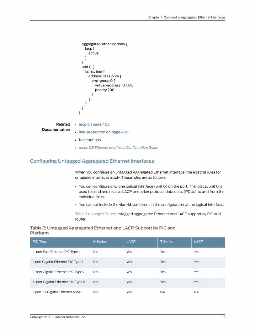
aggregated-ether-options {lacp {active;
}}unit 0 {family inet {address 10.1.1.2/24 {vrrp-group 0 {virtual-address 10.1.1.4;priority 200;
}}
}}
}
RelatedDocumentation
lacp on page 465•
• link-protection on page 469
• traceoptions
• Junos OS Ethernet Interfaces Configuration Guide
Configuring Untagged Aggregated Ethernet Interfaces
When you configure an untagged Aggregated Ethernet interface, the existing rules for
untagged interfaces apply. These rules are as follows:
• You can configure only one logical interface (unit 0) on the port. The logical unit 0 is
used to send and receive LACP or marker protocol data units (PDUs) to and from the
individual links.
• You cannot include the vlan-id statement in the configuration of the logical interface.
Table 7 on page 115 lists untagged aggregated Ethernet and LACP support by PIC and
router.
Table 7: Untagged Aggregated Ethernet and LACP Support by PIC andPlatform
LACPT SeriesLACPM SeriesPIC Type
YesYesYesYes4-port Fast Ethernet PIC Type 1
YesYesYesYes1-port Gigabit Ethernet PIC Type 1
YesYesYesYes2-port Gigabit Ethernet PIC Type 2
YesYesYesYes4-port Gigabit Ethernet PIC Type 2
NANAYesYes1-port 10-Gigabit Ethernet M160
115Copyright © 2011, Juniper Networks, Inc.
Chapter 4: Configuring Aggregated Ethernet Interfaces
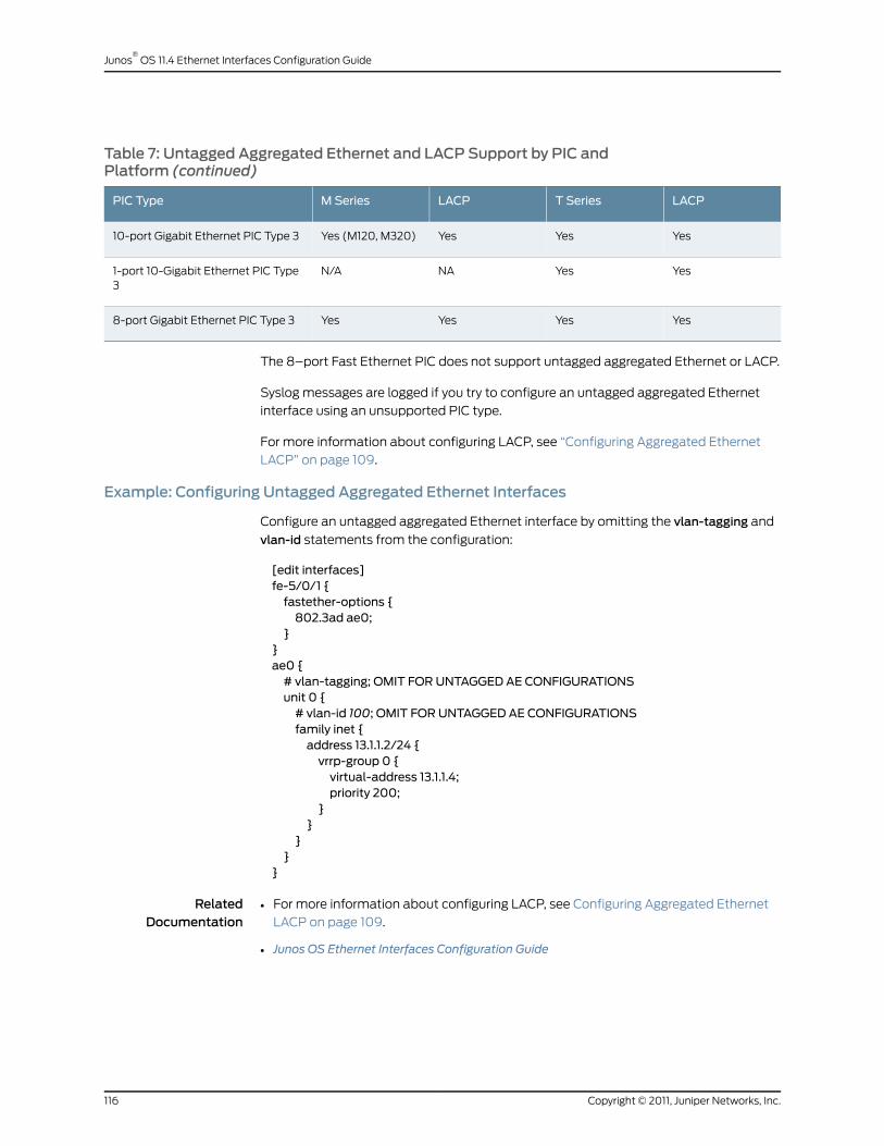
Table 7: Untagged Aggregated Ethernet and LACP Support by PIC andPlatform (continued)
LACPT SeriesLACPM SeriesPIC Type
YesYesYesYes (M120, M320)10-port Gigabit Ethernet PIC Type 3
YesYesNAN/A1-port 10-Gigabit Ethernet PIC Type3
YesYesYesYes8-port Gigabit Ethernet PIC Type 3
The 8–port Fast Ethernet PIC does not support untagged aggregated Ethernet or LACP.
Syslog messages are logged if you try to configure an untagged aggregated Ethernet
interface using an unsupported PIC type.
For more information about configuring LACP, see “Configuring Aggregated Ethernet
LACP” on page 109.
Example: Configuring Untagged Aggregated Ethernet Interfaces
Configure an untagged aggregated Ethernet interface by omitting the vlan-tagging and
vlan-id statements from the configuration:
[edit interfaces]fe-5/0/1 {fastether-options {802.3ad ae0;
}}ae0 {# vlan-tagging; OMIT FOR UNTAGGED AE CONFIGURATIONSunit 0 {# vlan-id 100; OMIT FOR UNTAGGED AE CONFIGURATIONSfamily inet {address 13.1.1.2/24 {vrrp-group 0 {virtual-address 13.1.1.4;priority 200;
}}
}}
}
RelatedDocumentation
For more information about configuring LACP, see Configuring Aggregated Ethernet
LACP on page 109.
•
• Junos OS Ethernet Interfaces Configuration Guide
Copyright © 2011, Juniper Networks, Inc.116
Junos®
OS 11.4 Ethernet Interfaces Configuration Guide
Configuring Aggregated Ethernet Link Speed
On aggregated Ethernet interfaces, you can set the required link speed for all interfaces
included in the bundle. All interfaces that make up a bundle must be the same speed. If
you include in the aggregated Ethernet interface an individual link that has a speed
different from the speed you specify in the link-speed parameter, an error message will
be logged.
To set the required link speed:
1. Specify that you want to configure the aggregated Ethernet options.
user@host# edit interfaces interface-name aggregated-ether-options
2. Configure the link speed.
[edit interfaces interface-name aggregated-ether-options ]user@host# set link-speed speed
speed can be in bits per second either as a complete decimal number or as a decimal
number followed by the abbreviation k (1000),m (1,000,000), or g (1,000,000,000).
Aggregated Ethernet interfaces on the M120 router can have one of the following
speed values:
• 100m—Links are 100 Mbps.
• 10g—Links are 10 Gbps.
• 1g—Links are 1 Gbps.
• OC192—Links are OC192 or STM64c.
Aggregated Ethernet links on EX Series switches can be configured to operate at one
of the following speeds:
• 10m
• 100m
• 1g
• 10g
• 50g
RelatedDocumentation
aggregated-ether-options on page 435•
• Junos OS Ethernet Interfaces Configuration Guide
Configuring Aggregated Ethernet Minimum Links
On aggregated Ethernet interfaces, you can configure the minimum number of links that
must be up for the bundle as a whole to be labeled up. By default, only one link must be
up for the bundle to be labeled up.
117Copyright © 2011, Juniper Networks, Inc.
Chapter 4: Configuring Aggregated Ethernet Interfaces
To configure the minimum number of links:
1. Specify that you want to configure the aggregated Ethernet options.
user@host# edit interfaces interface-name aggregated-ether-options
2. Configure the minimum number of links.
[edit interfaces interface-name aggregated-ether-options]user@host# setminimum-links number
On M120, M320, MX Series, T Series, and TX Matrix routers with Ethernet interfaces, the
valid range for minimum-links number is 1 through 16. When the maximum value (16) is
specified, all configured links of a bundle must be up for the bundle to be labeled up.
On all other routers and on EX Series switches, other than EX8200 switches, the range
of valid values for minimum-links number is 1 through 8. When the maximum value (8) is
specified, all configured links of a bundle must be up for the bundle to be labeled up.
On EX8200 switches, the range of valid values for minimum-links number is 1 through 12.
When the maximum value (12) is specified, all configured links of a bundle must be up
for the bundle to be labeled up.
If the number of links configured in an aggregated Ethernet interface is less than the
minimum link value configured under the aggregated-ether-options statement, the
configuration commit fails and an error message is displayed.
RelatedDocumentation
aggregated-ether-options on page 435•
• minimum-links on page 478
• Junos OS Ethernet Interfaces Configuration Guide
ConfiguringMulticast Statistics Collection on Aggregated Ethernet Interfaces
T Series and TX Matrix routers support multicast statistics collection on aggregated
Ethernet interfaces in both ingress and egress directions. The multicast statistics
functionality can be configured on a physical interface thus enabling multicast accounting
for all the logical interfaces below the physical interface.
The multicast statistics information is displayed only when the interface is configured
with the multicast-statistics statement, which is not enabled by default.
Multicast statistics collection requires at least one logical interface is configured with
family inet or inet6; otherwise, the commit for multicast-statistics will fail.
The multicast in/out statistics can be obtained via interfaces statistics query through
CLI and via MIB objects through SNMP query.
Copyright © 2011, Juniper Networks, Inc.118
Junos®
OS 11.4 Ethernet Interfaces Configuration Guide
To configure multicast statistics:
1. Include the multicast-statistics statement at the [edit interfaces interface-name]
hierarchy level.
An example of a multicast statistics configuration for an aggregated Ethernet interfacefollows:
[edit interfaces]ae0 {multicast-statistics;
}
To display multicast statistics, use the show interfaces interface-name statistics detail
command.
RelatedDocumentation
multicast-statistics•
• Configuring Multicast Statistics Collection on Ethernet Interfaces on page 50
• Junos OS Ethernet Interfaces Configuration Guide
Configuring Scheduler on Aggregated Ethernet InterfacesWithout Link Protection
On aggregated Ethernet interfaces, you can configure scheduler in non–link-protect
mode on the following platforms:
• MX-Series
• M120 and M320 with IQ2 PIC
• T-series platforms (T620 and T320) with IQ2 PIC
The scheduler functions supported are:
• Per unit scheduler
• Hierarchical scheduler
• Shaping at the physical interface
To configure the hierarchical scheduler on aggregated Ethernet interfaces in the non
link-protect mode, include the hierarchical-scheduler statement at the [edit interfaces
aeX] hierarchy level:
[edit interfaces aeX hierarchical-scheduler]
Prior to Junos OS Release 9.6, the hierarchical scheduler mode on these models required
theaggregated-ether-options statement link-protectionoption. If a link-protectionoption
is not specified, the scheduler is configured in non-link-protect mode.
To specify the member link bandwidth derivation based on the equal division model
(scale) or the replication model (replicate) on aggregated Ethernet interfaces, include
themember-link-scheduler (scale | replicate)option at the [edit class-of-service interfaces
aeX] hierarchy level. The default setting is scale.
119Copyright © 2011, Juniper Networks, Inc.
Chapter 4: Configuring Aggregated Ethernet Interfaces
[edit class-of-service interfaces aeXmember-link-scheduler (scale | replicate)]
NOTE: In link-protect mode, only one link is active at a time and the otherlink acts as the backup link, whereas in a non link-protect mode, all the linksof the aggregate bundle are active at the same time. There is no backup link.If a link goes down or a new link is added to the bundle, traffic redistributionoccurs.
RelatedDocumentation
Configuring Hierarchical CoS for a Subscriber Interface of Aggregated Ethernet Links•
• Junos OS Ethernet Interfaces Configuration Guide
• For more information on the hierarchical scheduler (CoS), see the Junos OS Class of
Service Configuration Guide.
Configuring Symmetrical Load Balancing on an 802.3ad Link Aggregation Group onMX Series Routers
This section describes configuration of symmetrical load balancing on an 802.3ad link
aggregation group (LAG) on MX Series routers.
• Symmetrical Load Balancing on an 802.3ad LAG on MX Series Routers
Overview on page 120
• Configuring Symmetric Load Balancing on an 802.3ad LAG on MX Series
Routers on page 121
• Example Configurations on page 124
Symmetrical Load Balancing on an 802.3ad LAG onMX Series Routers Overview
MX Series routers with Aggregated Ethernet PICs support symmetrical load balancing
on an 802.3ad LAG. This feature is significant when two MX Series routers are connected
transparently through deep packet inspection (DPI) devices over an LAG bundle. DPI
devices keep track of flows and require information of a given flow in both forward and
reverse directions. Without symmetrical load balancing on an 802.3ad LAG, the DPIs
could misunderstand the flow, leading to traffic disruptions. By using this feature, a given
flow of traffic (duplex) is ensured for the same devices in both directions.
Symmetrical load balancing on an 802.3ad LAG utilizes a mechanism of interchanging
the source and destination addresses for a hash computation of fields, such as source
address and destination address. The result of a hash computed on these fields is used
to choose the link of the LAG. The hash-computation for the forward and reverse flow
must be identical. This is achieved by swapping source fields with destination fields for
the reverse flow. The swapped operation is referred to as complement hash computation
or symmetric-hash complement and the regular (or unswapped) operation as
symmetric-hash computationor symmetric-hash. The swappable fields are MAC address,
IP address, and port.
Copyright © 2011, Juniper Networks, Inc.120
Junos®
OS 11.4 Ethernet Interfaces Configuration Guide

Configuring Symmetric Load Balancing on an 802.3ad LAG onMX Series Routers
You can specify whether symmetric hash or complement hash is done for load-balancing
traffic. To configure symmetric hash, use the symmetric-hash statement at the [edit
forwarding-options hash-key family inet] hierarchy level. To configure symmetric hash
complement, use the symmetric-hash complement statement and option at the [edit
forwarding-options hash-key family inet] hierarchy level.
These operations can also be performed at the PIC level by specifying a hash key. To
configure a hash key at the PIC level, use the symmetric-hash or symmetric-hash
complement statement at the [editchassishash-keyfamily inet]and [editchassishash-key
family multiservice] hierarchy levels.
Consider the example in Figure 14 on page 121.
Figure 14: Symmetric Load Balancing on an 802.3ad LAG onMX SeriesRouters
A
MX-series router
B
MX-series router
i1
i2
i3
A
A
Forward traffic
Reverse traffic
B
B
Intelligent Devices
g017
349
Router A is configured with symmetric hash and Router B is configured with symmetric
hash complement. Thus, for a given flow fx, post hash computation is from Router A to
Router B through i2. The reverse traffic for the same flow fx is from Router B to Router A
through the same i2 device as its hashing (done after swapping source and destination
fields) and returns the same link index; since it is performed on the interchanged source
and destination addresses.
However, the link chosen may or may not correspond to what was attached to the DPI.
In other words, the hashing result should point to the same links that are connected, so
that the traffic flows through the same DPI devices in both directions. To make sure this
happens, you need to also configure the counterpart ports (ports that are connected to
same DPI-iN) with the identical link index. This is done when configuring a child-link into
the LAG bundle. This ensures that the link chosen for a given hash result is always the
same on either router.
Note that any two links connected to each other should have the same link index and
these link indices must be unique in a given bundle.
121Copyright © 2011, Juniper Networks, Inc.
Chapter 4: Configuring Aggregated Ethernet Interfaces

NOTE:
The following restrictions apply when configuring symmetric load balancingon an 802.3ad LAG onMX Series routers:
• The Packet Forwarding Engine (PFE) can be configured to hash the trafficin either symmetric or complementmode. A single PFE complex cannotwork simultaneously in both operational modes and such a configurationcan yield undesirable results.
• The per-PFE setting overrides the chassis-wide setting only for the familyconfigured. For the other families, the PFE complex still inherits thechassis-wide setting (when configured) or the default setting.
• Any change in the hash key configuration requires a reboot of the FPC forthe changes to take effect.
• This feature supports VPLS, INET, and bridged traffic only.
• This feature cannot work in tandemwith the per-flow-hash-seed
load-balancing option. It requires that all the PFE complexes configured in
complementary fashionshare thesameseed.Achange in theseedbetweentwo counterpart PFE complexesmay yield undesired results.
For additional information, see the Junos OS VPNs Configuration Guide and the Junos OS
System Basics Configuration Guide.
ExampleConfigurationStatements
To configure 802.3ad LAG parameters at the bundle level:
[edit interfaces]g(x)e-fpc/pic/port {gigether-options {802.3ad {bundle;link-index number;
}}
}
where the link-index number ranges from 0 through 15.
You can check the link index configured above using the show interfaces command:
[edit forwarding-options hash-key]family inet {layer-3;layer-4;symmetric-hash {[complement;]
}}family multiservice {source-mac;destination-mac;payload {
Copyright © 2011, Juniper Networks, Inc.122
Junos®
OS 11.4 Ethernet Interfaces Configuration Guide
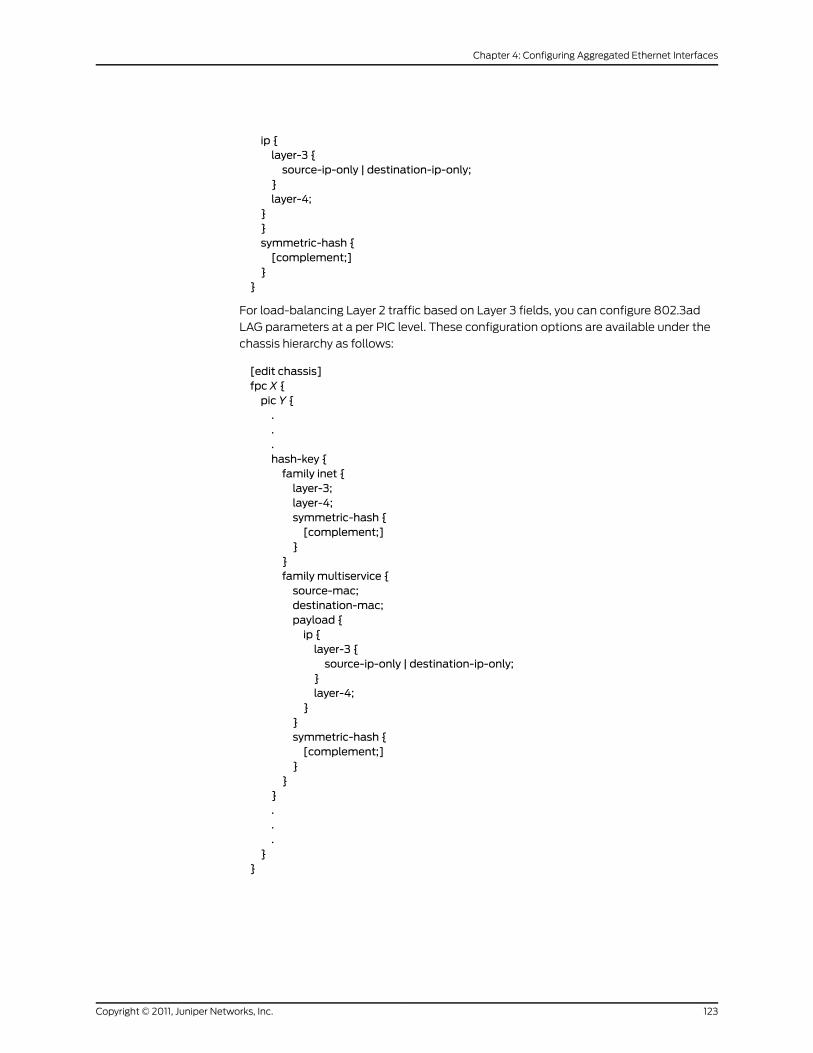
ip {layer-3 {source-ip-only | destination-ip-only;
}layer-4;
}}symmetric-hash {[complement;]
}}
For load-balancing Layer 2 traffic based on Layer 3 fields, you can configure 802.3ad
LAG parameters at a per PIC level. These configuration options are available under the
chassis hierarchy as follows:
[edit chassis]fpc X {pic Y {...hash-key {family inet {layer-3;layer-4;symmetric-hash {[complement;]
}}family multiservice {source-mac;destination-mac;payload {ip {layer-3 {source-ip-only | destination-ip-only;
}layer-4;
}}symmetric-hash {[complement;]
}}
}...
}}
123Copyright © 2011, Juniper Networks, Inc.
Chapter 4: Configuring Aggregated Ethernet Interfaces
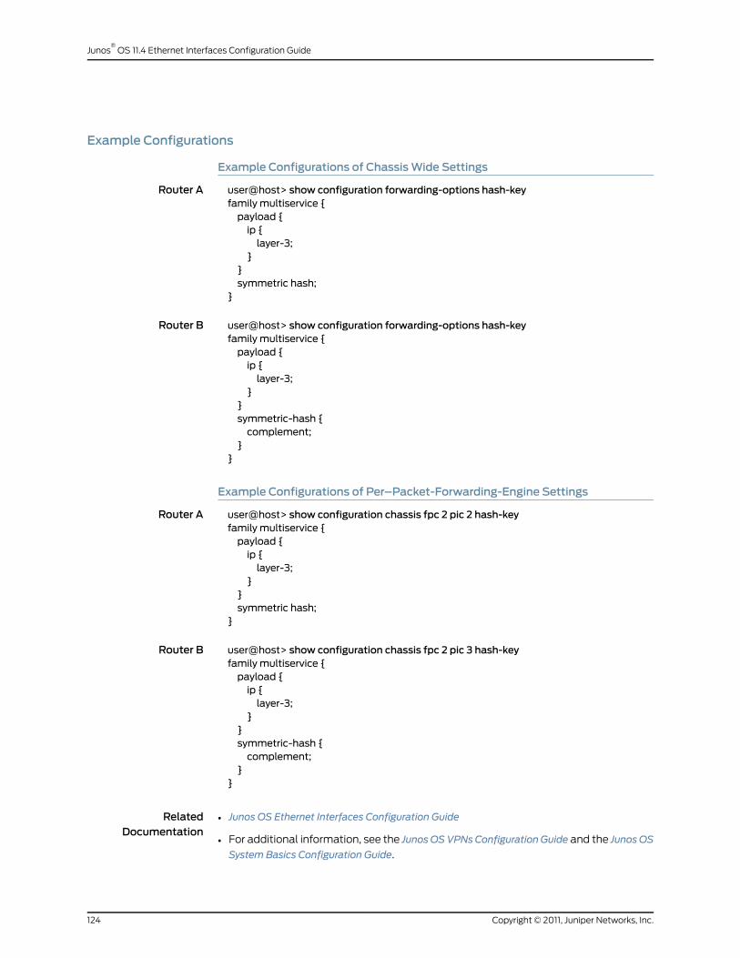
Example Configurations
Example Configurations of ChassisWide Settings
Router A user@host> show configuration forwarding-options hash-keyfamily multiservice {payload {ip {layer-3;
}}symmetric hash;
}
Router B user@host> show configuration forwarding-options hash-keyfamily multiservice {payload {ip {layer-3;
}}symmetric-hash {complement;
}}
Example Configurations of Per–Packet-Forwarding-Engine Settings
Router A user@host> show configuration chassis fpc 2 pic 2 hash-keyfamily multiservice {payload {ip {layer-3;
}}symmetric hash;
}
Router B user@host> show configuration chassis fpc 2 pic 3 hash-keyfamily multiservice {payload {ip {layer-3;
}}symmetric-hash {complement;
}}
RelatedDocumentation
• Junos OS Ethernet Interfaces Configuration Guide
• For additional information, see the JunosOSVPNsConfiguration Guide and the JunosOS
System Basics Configuration Guide.
Copyright © 2011, Juniper Networks, Inc.124
Junos®
OS 11.4 Ethernet Interfaces Configuration Guide
CHAPTER 5
Stacking and Rewriting Gigabit EthernetVLAN Tags
• Stacking and Rewriting Gigabit Ethernet VLAN Tags Overview on page 125
• Stacking and Rewriting Gigabit Ethernet VLAN Tags on page 126
• Configuring Frames with Particular TPIDs to Be Processed as Tagged Frames on page 129
• Configuring Stacked VLAN Tagging on page 130
• Configuring Dual VLAN Tags on page 130
• Configuring Inner and Outer TPIDs and VLAN IDs on page 131
• Stacking a VLAN Tag on page 134
• Removing a VLAN Tag on page 135
• Removing the Outer and Inner VLAN Tags on page 135
• Removing the Outer VLAN Tag and Rewriting the Inner VLAN Tag on page 136
• Stacking Two VLAN Tags on page 137
• Rewriting the VLAN Tag on Tagged Frames on page 138
• Rewriting a VLAN Tag on Untagged Frames on page 139
• Rewriting a VLAN Tag and Adding a New Tag on page 142
• Rewriting the Inner and Outer VLAN Tags on page 142
• Examples: Stacking and Rewriting Gigabit Ethernet IQ VLAN Tags on page 143
Stacking and Rewriting Gigabit Ethernet VLAN Tags Overview
Stacking and rewriting VLAN tags allows you to use an additional (outer) VLAN tag to
differentiate between customer edge (CE) routers that share one VLAN ID. A frame can
be received on an interface, or it can be internal to the system (as a result of the
input-vlan-map statement).
On IQ2 interfaces, 10-Gigabit Ethernet LAN/WAN PIC, IQ2-E interfaces, and MX Series
interfaces, when a VLAN tag is pushed, the inner VLAN IEEE 802.1p bits are copied to the
IEEE bits of the VLAN or VLANs being pushed. If the original packet is untagged, the IEEE
bits of the VLAN or VLANs being pushed are set to 0.
125Copyright © 2011, Juniper Networks, Inc.

NOTE: When swap-by-poppush is configured on the interface,whenaVLANtag is swapped, the inner VLAN IEEE 802.1p bits are copied to the IEEE bitsof the VLAN being swapped. If swap-by-poppush is not configured on theinterface, the VLAN IEEE 802.1p bits of the of the VLAN being swappedremains same.
You can stack and rewrite VLAN tags on the following interfaces:
• Gigabit Ethernet
• Gigabit Ethernet IQ
• 10-Gigabit Ethernet LAN/WAN PIC
• Gigabit Ethernet IQ2 and IQ2-E
• 10-Gigabit Ethernet IQ2 and IQ2-E interfaces, and MX Series router Gigabit Ethernet
Interfaces
• Tri-Rate Ethernet copper, and 10-Gigabit Ethernet interfaces with the VLAN
encapsulation type configured to support Layer 2 tunneling protocols such as circuit
cross-connect (CCC) or virtual private LAN service (VPLS) (as described in “802.1Q
VLANs Overview” on page 53)
RelatedDocumentation
802.1Q VLANs Overview on page 53•
• Stacking and Rewriting Gigabit Ethernet VLAN Tags on page 126
• Junos OS Ethernet Interfaces Configuration Guide
Stacking and Rewriting Gigabit Ethernet VLAN Tags
You can configure rewrite operations to stack (push), remove (pop), or rewrite (swap)
tags on single-tagged frames and dual-tagged frames. If a port is not tagged, rewrite
operations are not supported on any logical interface on that port.
You can configure the following VLAN rewrite operations:
• pop—Remove a VLAN tag from the top of the VLAN tag stack. The outer VLAN tag of
the frame is removed.
• pop-pop—For Ethernet IQ2, 10-Gigabit Ethernet LAN/WAN PIC, and IQ2-E interfaces,
remove both the outer and inner VLAN tags of the frame.
• pop-swap—For Ethernet IQ2, 10-Gigabit Ethernet LAN/WAN PIC, and IQ2-E interfaces,
remove the outer VLAN tag of the frame, and replace the inner VLAN tag of the frame
with a user-specified VLAN tag value. The inner tag becomes the outer tag in the final
frame.
• push—Add a new VLAN tag to the top of the VLAN stack. An outer VLAN tag is pushed
in front of the existing VLAN tag.
Copyright © 2011, Juniper Networks, Inc.126
Junos®
OS 11.4 Ethernet Interfaces Configuration Guide

• push-push—For Ethernet IQ2, 10-Gigabit Ethernet LAN/WAN PIC, and IQ2-E interfaces,
push two VLAN tags in front of the frame.
• swap-push—For Ethernet IQ2, 10-Gigabit Ethernet LAN/WAN PIC, and IQ2-E interfaces,
replace the outer VLAN tag of the frame with a user-specified VLAN tag value. A
user-specified outer VLAN tag is pushed in front. The outer tag becomes an inner tag
in the final frame.
• swap-swap—For Ethernet IQ2, 10-Gigabit Ethernet LAN/WAN PIC, and IQ2-E interfaces,
replace both the inner and the outer VLAN tags of the incoming frame with a
user-specified VLAN tag value.
You configure VLAN rewrite operations for logical interfaces in the input VLAN map for
incoming frames and in the output VLAN map for outgoing frames. To configure the input
VLAN map, include the input-vlan-map statement:
input-vlan-map {...interface-specific configuration...
}
To configure the output VLAN map, include the output-vlan-map statement:
output-vlan-map {...interface-specific configuration...
}
You can include both statements at the following hierarchy levels:
• [edit interfaces interface-name unit logical-unit-number]
• [edit logical-systems logical-system-name interfaces interface-name unit
logical-unit-number]
The type of VLAN rewrite operation permitted depends upon whether the frame is
single-tagged or dual-tagged. Table 8 on page 127 shows supported rewrite operations
and whether they can be applied to single-tagged frames or dual-tagged frames. The
table also indicates the number of tags being added or removed during the operation.
Table 8: Rewrite Operations on Untagged, Single-Tagged, andDual-Tagged Frames
Number of TagsDual-TaggedSingle-TaggedUntaggedRewrite Operation
– 1YesYesNopop
+1YesYesSometimespush
0YesYesNoswap
+2YesYesSometimespush-push
+1YesYesNoswap-push
0YesNoNoswap-swap
127Copyright © 2011, Juniper Networks, Inc.
Chapter 5: Stacking and Rewriting Gigabit Ethernet VLAN Tags

Table 8: Rewrite Operations on Untagged, Single-Tagged, andDual-Tagged Frames (continued)
Number of TagsDual-TaggedSingle-TaggedUntaggedRewrite Operation
– 2YesNoNopop-pop
– 1YesNoNopop-swap
The rewrite operations push and push-push can be valid in certain circumstances on
frames that are not tagged. For example, a single-tagged logical interface (interface 1)
and a dual-tagged logical interface (interface 2) have the following configurations:
Interface 1 [edit interfaces interface-name unit logical-unit-number]input-vlan-map {pop;
}output-vlan-map {push;
}
Interface 2 [edit interfaces interface-name unit logical-unit-number]input-vlan-map {pop-pop;
}output-vlan-map {push-push;
}
When a frame is received on the interface as a result of the input-vlan-map operation,
the frame is not tagged. As it goes out of the second interface, the output-vlan-map
operationpush-push is applied to it. The resulting frame will be dual-tagged at the logical
interface output.
Depending on the VLAN rewrite operation, you configure the rewrite operation for the
interface in the input VLAN map, the output VLAN map, or in both the input VLAN map
and the output VLAN map. Table 9 on page 128 shows what rewrite operation combinations
you can configure. “None” means that no rewrite operation is specified for the VLAN map.
Table 9: Applying Rewrite Operations to VLANMaps
Output VLANMap
swap-poppop-popswap-swapswap-pushpush-pushswappoppushnoneInput VLANMap
NoNoYesNoNoYesNoNoYesnone
NoNoNoNoNoNoYesNoNopush
NoNoNoNoNoNoNoYesNopop
NoNoNoNoNoYesNoNoYesswap
Copyright © 2011, Juniper Networks, Inc.128
Junos®
OS 11.4 Ethernet Interfaces Configuration Guide

Table 9: Applying Rewrite Operations to VLANMaps (continued)
Output VLANMap
swap-poppop-popswap-swapswap-pushpush-pushswappoppushnoneInput VLANMap
NoYesNoNoNoNoNoNoNopush-push
YesNoNoNoNoNoNoNoNoswap-push
NoNoYesNoNoNoNoNoYesswap-swap
NoNoNoNoYesNoNoNoNopop-pop
NoNoNoYesNoNoNoNoNopop-swap
You must know whether the VLAN rewrite operation is valid and is applied to the input
VLAN map or the output VLAN map. You must also know whether the rewrite operation
requires you to include statements to configure the inner and outer TPIDs and inner and
outer VLAN IDs in the input VLAN map or output VLAN map. For information about
configuring inner and outer TPIDs and inner and outer VLAN IDs, see “Configuring Inner
and Outer TPIDs and VLAN IDs” on page 131.
RelatedDocumentation
Stacking and Rewriting Gigabit Ethernet VLAN Tags Overview on page 125•
• Understanding swap-by-poppush
• swap-by-poppush
• Junos OS Ethernet Interfaces Configuration Guide
Configuring Frameswith Particular TPIDs to Be Processed as Tagged Frames
For Gigabit Ethernet IQ interfaces, aggregated Ethernet with Gigabit Ethernet IQ interfaces,
Gigabit Ethernet PICs with SFPs (except the 10-port Gigabit Ethernet PIC and the built-in
Gigabit Ethernet port on the M7i router), and MX Series router Gigabit Ethernet, Tri-Rate
Ethernet copper, and 10-Gigabit Ethernet interfaces, you can configure frames with
particular TPIDs to be processed as tagged frames. To do this, you specify up to eight
IEEE 802.1Q TPID values per port; a frame with any of the specified TPIDs is processed
as a tagged frame; however, with IQ2 and IQ2-E interfaces, only the first four IEEE 802.1Q
TPID values per port are supported. To configure the TPID values, include the
tag-protocol-id statement:
tag-protocol-id [ tpids ];
You can include this statement at the following hierarchy levels:
• [edit interfaces interface-name gigether-options ethernet-switch-profile]
• [edit interfaces interface-name aggregated-ether-options ethernet-switch-profile]
129Copyright © 2011, Juniper Networks, Inc.
Chapter 5: Stacking and Rewriting Gigabit Ethernet VLAN Tags
All TPIDs you include in input and output VLAN maps must be among those you specify
at the [edit interfaces interface-name gigether-options ethernet-switch-profile
tag-protocol-id [ tpids ]] or [edit interfaces interface-name aggregated-ether-options
ethernet-switch-profile tag-protocol-id [ tpids ]] hierarchy level.
RelatedDocumentation
Stacking and Rewriting Gigabit Ethernet VLAN Tags Overview on page 125•
• aggregated-ether-options on page 435
• ethernet-switch-profile on page 446
• gigether-options on page 453
• tag-protocol-id on page 515
• Junos OS Ethernet Interfaces Configuration Guide
Configuring Stacked VLAN Tagging
To configure stacked VLAN tagging for all logical interfaces on a physical interface,
include the stacked-vlan-tagging statement at the [edit interfaces interface-name]
hierarchy level:
[edit interfaces interface-name]stacked-vlan-tagging;
If you include the stacked-vlan-tagging statement in the configuration, you must configure
dual VLAN tags for all logical interfaces on the physical interface. For more information,
see “Stacking a VLAN Tag” on page 134.
RelatedDocumentation
stacked-vlan-tagging•
• Stacking a VLAN Tag on page 134
• Junos OS Ethernet Interfaces Configuration Guide
Configuring Dual VLAN Tags
To configure dual VLAN tags on a logical interface, include the vlan-tags statement:
vlan-tags inner <tpid.>vlan-id outer <tpid.>vlan-id;
You can include this statement at the following hierarchy levels:
• [edit interfaces interface-name unit logical-unit-number]
• [edit logical-systems logical-system-name interfaces interface-name unit
logical-unit-number]
The outer tag VLAN ID range is from 1 through 511 for normal interfaces, and from 512
through 4094 for VLAN CCC or VLAN VPLS interfaces. The inner tag is not restricted.
You must also include the stacked-vlan-tagging statement in the configuration. See
“Examples: Stacking and Rewriting Gigabit Ethernet IQ VLAN Tags” on page 143.
Copyright © 2011, Juniper Networks, Inc.130
Junos®
OS 11.4 Ethernet Interfaces Configuration Guide

RelatedDocumentation
unit on page 520•
• Examples: Stacking and Rewriting Gigabit Ethernet IQ VLAN Tags on page 143
• Junos OS Ethernet Interfaces Configuration Guide
Configuring Inner and Outer TPIDs and VLAN IDs
For some rewrite operations, you must configure the inner or outer TPID values and inner
or outer VLAN ID values. These values can be applied to either the input VLAN map or
the output VLAN map.
On Ethernet IQ, IQ2, and IQ2-E interfaces; on MX Series router Gigabit Ethernet, Tri-RateEthernet copper, and 10-Gigabit Ethernet interfaces; and on aggregated Ethernetinterfaces using Gigabit Ethernet IQ2 and IQ2-E or 10-Gigabit Ethernet PICs on MX Seriesrouters, to configure the inner TPID, include the inner-tag-protocol-id statement:
inner-tag-protocol-id tpid;
You can include this statement at the following hierarchy levels:
• [edit interfaces interface-name unit logical-unit-number input-vlan-map]
• [edit interfaces interface-name unit logical-unit-number output-vlan-map]
• [edit logical-systems logical-system-name interfaces interface-name unit
logical-unit-number input-vlan-map]
• [edit logical-systems logical-system-name interfaces interface-name unit
logical-unit-number output-vlan-map]
For the inner VLAN ID, include the inner-vlan-id statement. For the outer TPID, include
the tag-protocol-id statement. For the outer VLAN ID, include the vlan-id statement:
input-vlan-map {(pop | pop-pop | pop-swap | push | push-push | swap | swap-push | swap-swap);inner-tag-protocol-id tpid;inner-vlan-id number;tag-protocol-id tpid;vlan-id number;
}output-vlan-map {(pop | pop-pop | pop-swap | push | push-push | swap | swap-push | swap-swap);inner-tag-protocol-id tpid;inner-vlan-id number;tag-protocol-id tpid;vlan-id number;
}
For aggregated Ethernet interfaces using Gigabit Ethernet IQ interfaces, include the
tag-protocol-id statement for the outer TPID. For the outer VLAN ID, include the vlan-id
statement:
input-vlan-map {(pop | push | swap);tag-protocol-id tpid;
131Copyright © 2011, Juniper Networks, Inc.
Chapter 5: Stacking and Rewriting Gigabit Ethernet VLAN Tags
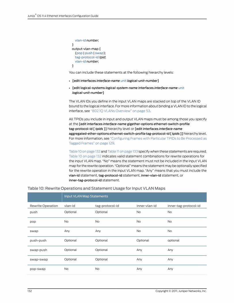
vlan-id number;}output-vlan-map {(pop | push | swap);tag-protocol-id tpid;vlan-id number;
}
You can include these statements at the following hierarchy levels:
• [edit interfaces interface-name unit logical-unit-number]
• [edit logical-systems logical-system-name interfaces interface-name unit
logical-unit-number]
The VLAN IDs you define in the input VLAN maps are stacked on top of the VLAN ID
bound to the logical interface. For more information about binding a VLAN ID to the logical
interface, see “802.1Q VLANs Overview” on page 53.
All TPIDs you include in input and output VLAN maps must be among those you specify
at the [edit interfaces interface-name gigether-options ethernet-switch-profile
tag-protocol-id [ tpids ]] hierarchy level or [edit interfaces interface-name
aggregated-ether-optionsethernet-switch-profile tag-protocol-id[ tpids]]hierarchy level.
For more information, see “Configuring Frames with Particular TPIDs to Be Processed as
Tagged Frames” on page 129.
Table 10 on page 132 and Table 11 on page 133 specify when these statements are required.
Table 10 on page 132 indicates valid statement combinations for rewrite operations for
the input VLAN map. “No” means the statement must not be included in the input VLAN
map for the rewrite operation. “Optional” means the statement may be optionally specified
for the rewrite operation in the input VLAN map. “Any” means that you must include the
vlan-id statement, tag-protocol-id statement, inner-vlan-id statement, or
inner-tag-protocol-id statement.
Table 10: RewriteOperations andStatementUsage for Input VLANMaps
Input VLANMap Statements
inner-tag-protocol-idinner-vlan-idtag-protocol-idvlan-idRewrite Operation
NoNoOptionalOptionalpush
NoNoNoNopop
NoNoAnyAnyswap
optionalOptionalOptionalOptionalpush-push
AnyAnyOptionalOptionalswap-push
AnyAnyOptionalOptionalswap-swap
AnyAnyNoNopop-swap
Copyright © 2011, Juniper Networks, Inc.132
Junos®
OS 11.4 Ethernet Interfaces Configuration Guide

Table 10: Rewrite Operations and Statement Usage for Input VLANMaps (continued)
Input VLANMap Statements
NoNoNoNopop-pop
Table 11 on page 133 indicates valid statement combinations for rewrite operations for
the output VLAN map. “No” means the statement must not be included in the output
VLAN map for the rewrite operation. “Optional” means the statement may be optionally
specified for the rewrite operation in the output VLAN map.
Table 11:RewriteOperationsandStatementUsageforOutputVLANMaps
Output VLANMap Statements
inner-tag-protocol-idinner-vlan-idtag-protocol-idvlan-idRewrite Operation
NoNoOptionalNopush
NoNoNoNopop
NoNoOptionalNoswap
OptionalNoOptionalNopush-push
OptionalNoOptionalNoswap-push
OptionalNoOptionalNoswap-swap
OptionalNoNoNopop-swap
NoNoNoNopop-pop
The following examples use Table 10 on page 132 and Table 11 on page 133 and show how
the pop-swap operation can be configured in an input VLAN map and an output VLAN
map:
Input VLANMapwithinner-vlan-id
[edit interfaces interface-name unit logical-unit-number]input-vlan-map {pop-swap;Statement, Outputinner-vlan-id number;VLANMapwith
}Optional
output-vlan-map {inner-tag-protocol-id
Statementpop-swap;inner-tag-protocol-id tpid;
}
Input VLANMapwithinner-tag-protocol-id
[edit interfaces interface-name unit logical-unit-number]input-vlan-map {pop-swap;Statement, Outputinner-tag-protocol-id tpid;VLANMapwith
133Copyright © 2011, Juniper Networks, Inc.
Chapter 5: Stacking and Rewriting Gigabit Ethernet VLAN Tags
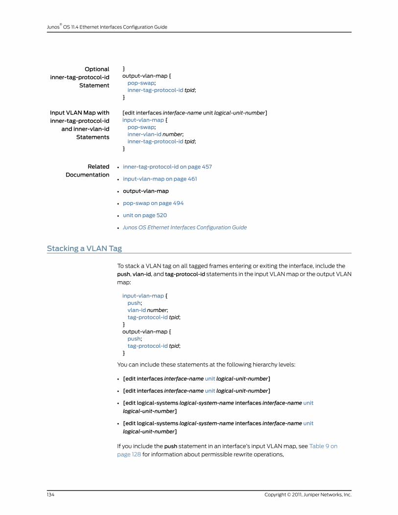
}Optionalinner-tag-protocol-id
Statement
output-vlan-map {pop-swap;inner-tag-protocol-id tpid;
}
Input VLANMapwithinner-tag-protocol-id
[edit interfaces interface-name unit logical-unit-number]input-vlan-map {pop-swap;and inner-vlan-id
Statements inner-vlan-id number;inner-tag-protocol-id tpid;
}
RelatedDocumentation
inner-tag-protocol-id on page 457•
• input-vlan-map on page 461
• output-vlan-map
• pop-swap on page 494
• unit on page 520
• Junos OS Ethernet Interfaces Configuration Guide
Stacking a VLAN Tag
To stack a VLAN tag on all tagged frames entering or exiting the interface, include the
push, vlan-id, and tag-protocol-id statements in the input VLAN map or the output VLAN
map:
input-vlan-map {push;vlan-id number;tag-protocol-id tpid;
}output-vlan-map {push;tag-protocol-id tpid;
}
You can include these statements at the following hierarchy levels:
• [edit interfaces interface-name unit logical-unit-number]
• [edit interfaces interface-name unit logical-unit-number]
• [edit logical-systems logical-system-name interfaces interface-name unit
logical-unit-number]
• [edit logical-systems logical-system-name interfaces interface-name unit
logical-unit-number]
If you include the push statement in an interface’s input VLAN map, see Table 9 on
page 128 for information about permissible rewrite operations,
Copyright © 2011, Juniper Networks, Inc.134
Junos®
OS 11.4 Ethernet Interfaces Configuration Guide
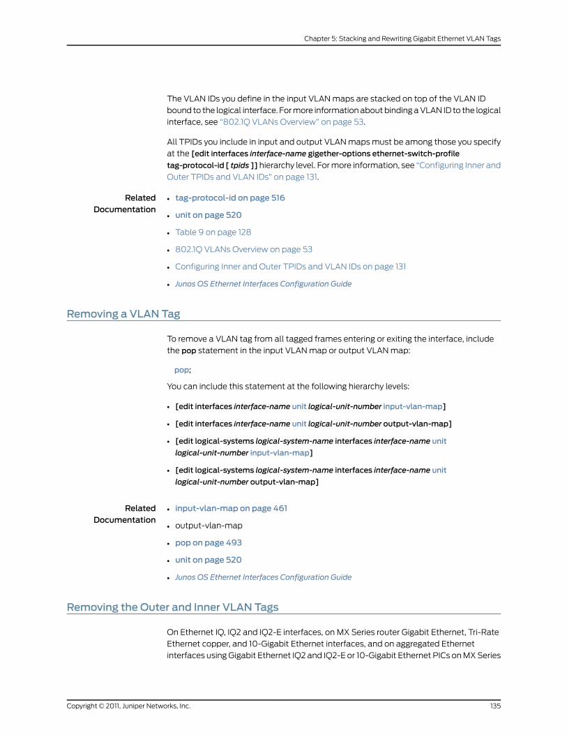
The VLAN IDs you define in the input VLAN maps are stacked on top of the VLAN ID
bound to the logical interface. For more information about binding a VLAN ID to the logical
interface, see “802.1Q VLANs Overview” on page 53.
All TPIDs you include in input and output VLAN maps must be among those you specify
at the [edit interfaces interface-name gigether-options ethernet-switch-profile
tag-protocol-id [ tpids ]] hierarchy level. For more information, see “Configuring Inner and
Outer TPIDs and VLAN IDs” on page 131.
RelatedDocumentation
tag-protocol-id on page 516•
• unit on page 520
• Table 9 on page 128
• 802.1Q VLANs Overview on page 53
• Configuring Inner and Outer TPIDs and VLAN IDs on page 131
• Junos OS Ethernet Interfaces Configuration Guide
Removing a VLAN Tag
To remove a VLAN tag from all tagged frames entering or exiting the interface, include
the pop statement in the input VLAN map or output VLAN map:
pop;
You can include this statement at the following hierarchy levels:
• [edit interfaces interface-name unit logical-unit-number input-vlan-map]
• [edit interfaces interface-name unit logical-unit-number output-vlan-map]
• [edit logical-systems logical-system-name interfaces interface-name unit
logical-unit-number input-vlan-map]
• [edit logical-systems logical-system-name interfaces interface-name unit
logical-unit-number output-vlan-map]
RelatedDocumentation
input-vlan-map on page 461•
• output-vlan-map
• pop on page 493
• unit on page 520
• Junos OS Ethernet Interfaces Configuration Guide
Removing the Outer and Inner VLAN Tags
On Ethernet IQ, IQ2 and IQ2-E interfaces, on MX Series router Gigabit Ethernet, Tri-Rate
Ethernet copper, and 10-Gigabit Ethernet interfaces, and on aggregated Ethernet
interfaces using Gigabit Ethernet IQ2 and IQ2-E or 10-Gigabit Ethernet PICs on MX Series
135Copyright © 2011, Juniper Networks, Inc.
Chapter 5: Stacking and Rewriting Gigabit Ethernet VLAN Tags

routers, to remove both the outer and inner VLAN tags of the frame, include the pop-pop
statement in the input VLAN map or output VLAN map:
pop-pop;
You can include this statement at the following hierarchy levels:
• [edit interfaces interface-name unit logical-unit-number input-vlan-map]
• [edit interfaces interface-name unit logical-unit-number output-vlan-map]
• [edit logical-systems logical-system-name interfaces interface-name unit
logical-unit-number input-vlan-map]
• [edit logical-systems logical-system-name interfaces interface-name unit
logical-unit-number output-vlan-map]
See Table 10 on page 132 and Table 11 on page 133 for information about configuring inner
and outer VLAN ID values and inner and outer TPID values required for VLAN maps.
RelatedDocumentation
input-vlan-map on page 461•
• output-vlan-map
• pop-pop on page 493
• unit on page 520
• See Table 10 on page 132 and Table 11 on page 133 for information about configuring
inner and outer VLAN ID values and inner and outer TPID values required for VLAN
maps.
• Junos OS Ethernet Interfaces Configuration Guide
Removing the Outer VLAN Tag and Rewriting the Inner VLAN Tag
On Ethernet IQ, IQ2 and IQ2-E interfaces, on MX Series router Gigabit Ethernet, Tri-Rate
Ethernet copper, and 10-Gigabit Ethernet interfaces, and on aggregated Ethernet
interfaces using Gigabit Ethernet IQ2 and IQ2-E or 10-Gigabit Ethernet PICs on MX Series
routers, to remove the outer VLAN tag of the frame and replace the inner VLAN tag of
the frame with a user-specified VLAN tag value, include the pop-swap statement in the
input VLAN map or output VLAN map:
pop-swap;
The inner tag becomes the outer tag in the final frame.
You can include this statement at the following hierarchy levels:
• [edit interfaces interface-name unit logical-unit-number input-vlan-map]
• [edit interfaces interface-name unit logical-unit-number output-vlan-map]
Copyright © 2011, Juniper Networks, Inc.136
Junos®
OS 11.4 Ethernet Interfaces Configuration Guide

• [edit logical-systems logical-system-name interfaces interface-name unit
logical-unit-number input-vlan-map]
• [edit logical-systems logical-system-name interfaces interface-name unit
logical-unit-number output-vlan-map]
See Table 10 on page 132 and Table 11 on page 133 for information about configuring inner
and outer VLAN ID values and inner and outer TPID values required for VLAN maps.
RelatedDocumentation
input-vlan-map on page 461•
• output-vlan-map
• pop-swap on page 494
• unit on page 520
• See Table 10 on page 132 and Table 11 on page 133 for information about configuring
inner and outer VLAN ID values and inner and outer TPID values required for VLAN
maps.
• Junos OS Ethernet Interfaces Configuration Guide
Stacking Two VLAN Tags
On Ethernet IQ, IQ2 and IQ2-E interfaces, on MX Series router Gigabit Ethernet, Tri-Rate
Ethernet copper, and 10-Gigabit Ethernet interfaces, and on aggregated Ethernet
interfaces using Gigabit Ethernet IQ2 and IQ2-E or 10-Gigabit Ethernet PICs on MX Series
routers, to push two VLAN tags in front of tagged frames entering or exiting the interface,
include the push-push statement in the input VLAN map or the output VLAN map:
push-push;
You can include this statement at the following hierarchy levels:
• [edit interfaces interface-name unit logical-unit-number input-vlan-map]
• [edit interfaces interface-name unit logical-unit-number output-vlan-map]
• [edit logical-systems logical-system-name interfaces interface-name unit
logical-unit-number input-vlan-map]
• [edit logical-systems logical-system-name interfaces interface-name unit
logical-unit-number output-vlan-map]
See Table 10 on page 132 and Table 11 on page 133 for information about configuring inner
and outer VLAN ID values and inner and outer TPID values required for VLAN maps.
RelatedDocumentation
input-vlan-map on page 461•
• output-vlan-map
• pop on page 493
• unit on page 520
137Copyright © 2011, Juniper Networks, Inc.
Chapter 5: Stacking and Rewriting Gigabit Ethernet VLAN Tags
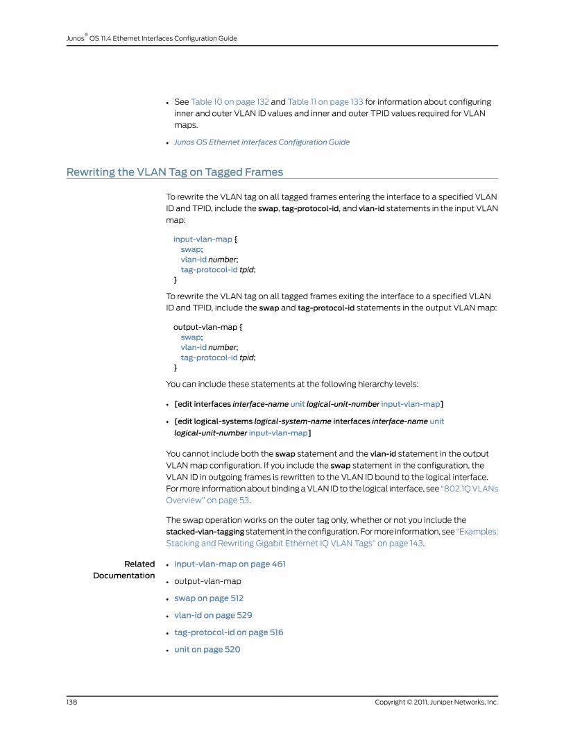
• See Table 10 on page 132 and Table 11 on page 133 for information about configuring
inner and outer VLAN ID values and inner and outer TPID values required for VLAN
maps.
• Junos OS Ethernet Interfaces Configuration Guide
Rewriting the VLAN Tag on Tagged Frames
To rewrite the VLAN tag on all tagged frames entering the interface to a specified VLAN
ID and TPID, include the swap, tag-protocol-id, and vlan-id statements in the input VLAN
map:
input-vlan-map {swap;vlan-id number;tag-protocol-id tpid;
}
To rewrite the VLAN tag on all tagged frames exiting the interface to a specified VLAN
ID and TPID, include the swap and tag-protocol-id statements in the output VLAN map:
output-vlan-map {swap;vlan-id number;tag-protocol-id tpid;
}
You can include these statements at the following hierarchy levels:
• [edit interfaces interface-name unit logical-unit-number input-vlan-map]
• [edit logical-systems logical-system-name interfaces interface-name unit
logical-unit-number input-vlan-map]
You cannot include both the swap statement and the vlan-id statement in the output
VLAN map configuration. If you include the swap statement in the configuration, the
VLAN ID in outgoing frames is rewritten to the VLAN ID bound to the logical interface.
For more information about binding a VLAN ID to the logical interface, see “802.1Q VLANs
Overview” on page 53.
The swap operation works on the outer tag only, whether or not you include the
stacked-vlan-taggingstatement in the configuration. For more information, see “Examples:
Stacking and Rewriting Gigabit Ethernet IQ VLAN Tags” on page 143.
RelatedDocumentation
input-vlan-map on page 461•
• output-vlan-map
• swap on page 512
• vlan-id on page 529
• tag-protocol-id on page 516
• unit on page 520
Copyright © 2011, Juniper Networks, Inc.138
Junos®
OS 11.4 Ethernet Interfaces Configuration Guide
• For more information about binding a VLAN ID to the logical interface, see 802.1Q
VLANs Overview on page 53.
• For more information about the swap operation, see Examples: Stacking and Rewriting
Gigabit Ethernet IQ VLAN Tags on page 143.
• Junos OS Ethernet Interfaces Configuration Guide
Rewriting a VLAN Tag on Untagged Frames
On M320, M120, and MX Series routers with Gigabit Ethernet IQ, IQ2, and IQ2E PICs,
10-Gigabit Ethernet IQ, IQ2, and IQ2E PICs, and on MX Series 40-port Gigabit Ethernet
R, 40-port Gigabit Ethernet R EQ, 4-port 10-Gigabit Ethernet R, and 4-port 10-Gigabit
Ethernet R EQ DPCs, you can rewrite VLAN tags on untagged incoming and outgoing
frames under ethernet-ccc and ethernet-vpls encapsulations. On MX Series routers with
IQ2 and IQ2-E PICs, you can perform all rewrite VLAN tag operations. These features
provide added flexibility.
Consider a network where two provider edges (PE) are connected by a Layer 2 circuit.
PE1 is receiving traffic on an untagged port while the corresponding port on PE2 is tagged.
In the normal case, packets coming from PE1 will be dropped at PE2 because it is expecting
tagged packets. However, if PE1 can push a VLAN tag on the incoming packet before
sending it across to PE2, you can ensure that packets are not dropped. To make it work
in both directions, PE1 must strip the VLAN tag from outgoing packets. Therefore, a push
on the ingress side is always paired with a pop on the egress side.
The rewrite operations represented by the following statement options are supported
under ethernet-ccc and ethernet-vpls encapsulations:
• push—A VLAN tag is added to the incoming untagged frame.
• pop—VLAN tag is removed from the outgoing frame.
• push-push—An outer and inner VLAN tag are added to the incoming untagged frame.
• pop-pop—Both the outer and inner VLAN tags of the outgoing frame are removed.
IQ2 and 10-Gigabit Ethernet PICs support all rewrite operations described above. Details
on the possible combinations of usage are explained later in this section.
NOTE: The push-push and pop-pop operations are not supported on the
Gigabit Ethernet IQ PIC.
For the input-vlan-map statement, only the push and push-push options are supported
because it does not make sense to remove a VLAN tag from an incoming untagged frame.
Similarly, only the pop and pop-pop options are supported for the output-vlan-map
statement. Also, with the push and push-push options, the tag parameters have to be
explicitly specified. Apart from this, the other rules for configuring the input-vlan-map
andoutput-vlan-map statements are the same as for tagged frames. Table 12 on page 140
through Table 14 on page 140 explain the rules in more detail.
139Copyright © 2011, Juniper Networks, Inc.
Chapter 5: Stacking and Rewriting Gigabit Ethernet VLAN Tags

For the input-vlan-map statement, only the push and push-push options are supported
because it does not make sense to remove a VLAN tag from an incoming untagged frame.
Similarly, only the pop and pop-pop options are supported for the output-vlan-map
statement. Also, with the push and push-push options, the vlan-id parameters (vlan-id
for push and vlan-id or inner-vlan-id for push-push) have to be explicitly specified. TPID
however, is optional and the default value of 0x8100 is set if not configured. Apart from
this, the other rules for configuring the input-vlan-map and output-vlan-map statements
are the same as for tagged frames.
Table 12: Input VLANMap Statements Allowed for ethernet-ccc and ethernet-vplsEncapsulations
inner-tag-protocol-idinner-vlan-idtag-protocol-idvlan-idOperation
OptionalNoOptionalYespush
OptionalYesOptionalYespush-push
Table 13: Output VLANMap Statements Allowed for ethernet-ccc and ethernet-vplsEncapsulations
inner-tag-protocol-idinner-vlan-idtag-protocol-idvlan-idOperation
NoNoNoNopop
NoNoNoNopop-pop
Table 14: Rules for Applying Rewrite Operations to VLANMaps
Output VLAN Map
pop-poppopNoneInput VLANMap
NoNoYesNone
NoYesNopush
YesNoNopush-push
Example:pushandpopwith Ethernet CCC
Encapsulation
ge-3/1/0 {encapsulation ethernet-ccc;unit 0 {encapsulation ethernet-ccc;input-vlan-map {push;tag-protocol-id 0x8100;vlan-id 600;
}output-vlan-map pop;family ccc;
}}
Copyright © 2011, Juniper Networks, Inc.140
Junos®
OS 11.4 Ethernet Interfaces Configuration Guide

Example: push-pushand pop-popwith
ge-3/1/0 {encapsulation ethernet-ccc;unit 0 {Ethernet CCC
Encapsulation encapsulation ethernet-ccc;input-vlan-map {push-push;tag-protocol-id 0x8100;inner-tag-protocol-id 0x8100;vlan-id 600;inner-vlan-id 575;
}output-vlan-map pop-pop;family ccc;
}}
Example:pushandpopwith Ethernet VPLS
Encapsulation
ge-3/1/0 {encapsulation ethernet-vpls;unit 0 {encapsulation ethernet-vpls;input-vlan-map {push;tag-protocol-id 0x8100;vlan-id 700;
}output-vlan-map pop;family vpls;
}}
Example: push-pushand pop-popwith
ge-3/1/0 {encapsulation ethernet-vpls;unit 0 {Ethernet VPLS
Encapsulation encapsulation ethernet-vpls;input-vlan-map {push-push;tag-protocol-id 0x8100;inner-tag-protocol-id 0x8100;vlan-id 600;inner-vlan-id 575;
}output-vlan-map pop-pop;family vpls;
}}
You can use the show interface interface-name command to display the status of a
modified VLAN map for the specified interface.
RelatedDocumentation
input-vlan-map on page 461•
• output-vlan-map
• pop on page 493
• pop-pop on page 493
141Copyright © 2011, Juniper Networks, Inc.
Chapter 5: Stacking and Rewriting Gigabit Ethernet VLAN Tags

• push on page 502
• push-push on page 503
• unit on page 520
• Junos OS Ethernet Interfaces Configuration Guide
Rewriting a VLAN Tag and Adding a New Tag
On Ethernet IQ, IQ2 and IQ2-E interfaces, on MX Series router Gigabit Ethernet, Tri-Rate
Ethernet copper, and 10-Gigabit Ethernet interfaces, and on aggregated Ethernet
interfaces using Gigabit Ethernet IQ2 and IQ2-E or 10-Gigabit Ethernet PICs on MX Series
routers, to replace the outer VLAN tag of the incoming frame with a user-specified VLAN
tag value, include the swap-push statement in the input VLAN map or output VLAN map:
swap-push
A user-specified outer VLAN tag is pushed in front. The outer tag becomes an inner tag
in the final frame.
You can include this statement at the following hierarchy levels:
• [edit interfaces interface-name unit logical-unit-number input-vlan-map]
• [edit interfaces interface-name unit logical-unit-number output-vlan-map]
• [edit logical-systems logical-system-name interfaces interface-name unit
logical-unit-number input-vlan-map]
• [edit logical-systems logical-system-name interfaces interface-name unit
logical-unit-number output-vlan-map]
See Table 10 on page 132 and Table 11 on page 133 for information about configuring inner
and outer VLAN ID values and inner and outer TPID values required for VLAN maps.
RelatedDocumentation
input-vlan-map on page 461•
• output-vlan-map
• swap-push on page 512
• unit on page 520
• Junos OS Ethernet Interfaces Configuration Guide
Rewriting the Inner and Outer VLAN Tags
On Ethernet IQ, IQ2 and IQ2-E interfaces, on MX Series router Gigabit Ethernet, Tri-Rate
Ethernet copper, and 10-Gigabit Ethernet interfaces, and on aggregated Ethernet
interfaces using Gigabit Ethernet IQ2 and IQ2-E or 10-Gigabit Ethernet PICs on MX Series
routers, to replace both the inner and the outer VLAN tags of the incoming frame with a
user-specified VLAN tag value, include the swap-swap statement in the input VLAN map
or output VLAN map:
Copyright © 2011, Juniper Networks, Inc.142
Junos®
OS 11.4 Ethernet Interfaces Configuration Guide

swap-swap;
You can include this statement at the following hierarchy levels:
• [edit interfaces interface-name unit logical-unit-number input-vlan-map]
• [edit interfaces interface-name unit logical-unit-number output-vlan-map]
• [edit logical-systems logical-system-name interfaces interface-name unit
logical-unit-number input-vlan-map]
• [edit logical-systems logical-system-name interfaces interface-name unit
logical-unit-number output-vlan-map]
See Table 10 on page 132 and Table 11 on page 133 for information about configuring inner
and outer VLAN ID values and inner and outer TPID values required for VLAN maps.
RelatedDocumentation
input-vlan-map on page 461•
• output-vlan-map
• swap-swap on page 513
• unit on page 520
• Junos OS Ethernet Interfaces Configuration Guide
Examples: Stacking and Rewriting Gigabit Ethernet IQ VLAN Tags
Configure a VLAN CCC tunnel in which Ethernet frames enter the tunnel at interface
ge-4/0/0 and exit the tunnel at interface ge-4/2/0.
The following examples show how to perform the following tasks:
• Push a TPID and VLAN ID Pair on Ingress on page 144
• Stack Inner and Outer VLAN Tags on page 144
• Swap a VLAN ID on Ingress on page 145
• Swap a VLAN ID on Egress on page 145
• Swap a VLAN ID on Both Ingress and Egress on page 146
• Swap the Outer VLAN Tag and Push a New VLAN Tag on Ingress; Pop the Outer VLAN
Tag and Swap the Inner VLAN Tag on Egress on page 147
• Swap a TPID and VLAN ID Pair for Both VLAN Tags on Ingress and on Egress on page 147
• Pop the Outer VLAN Tag and Swap the Inner VLAN Tag on Ingress; Swap the Outer
VLAN Tag and Push a New VLAN Tag on Egress on page 148
• Pop a TPID and VLAN ID Pair on Ingress; Push a VLAN ID and TPID Pair on Egress on
page 148
• Pop an Outer VLAN Tag to Connect an Untagged VPLS Interface to Tagged VPLS
Interfaces on page 149
143Copyright © 2011, Juniper Networks, Inc.
Chapter 5: Stacking and Rewriting Gigabit Ethernet VLAN Tags

Push aTPID andVLANID Pair on Ingress
[edit interfaces]ge-4/0/0 {vlan-tagging;encapsulation vlan-ccc;gigether-options {ethernet-switch-profile {tag-protocol-id 0x9909;
}}unit 0 {encapsulation vlan-ccc;vlan-id 512;input-vlan-map {push;tag-protocol-id 0x9909;vlan-id 520;
}output-vlan-map pop;
}}ge-4/2/0 {vlan-tagging;encapsulation vlan-ccc;unit 0 {encapsulation vlan-ccc;vlan-id 515;input-vlan-map {swap-push;vlan-id 520;inner-vlan-id 512;
}output-vlan-map {pop-swap;
}}[edit protocols]mpls {interface ge-4/0/0.0;interface ge-4/2/0.0;
}connections {interface-switch vlan-tag-push {interface ge-4/0/0.0;interface ge-4/2/0.0;
}}
}
Stack Inner and OuterVLAN Tags
[edit interfaces]ge-0/2/0 {stacked-vlan-tagging;mac 00.01.02.03.04.05;gigether-options {loopback;
}
Copyright © 2011, Juniper Networks, Inc.144
Junos®
OS 11.4 Ethernet Interfaces Configuration Guide
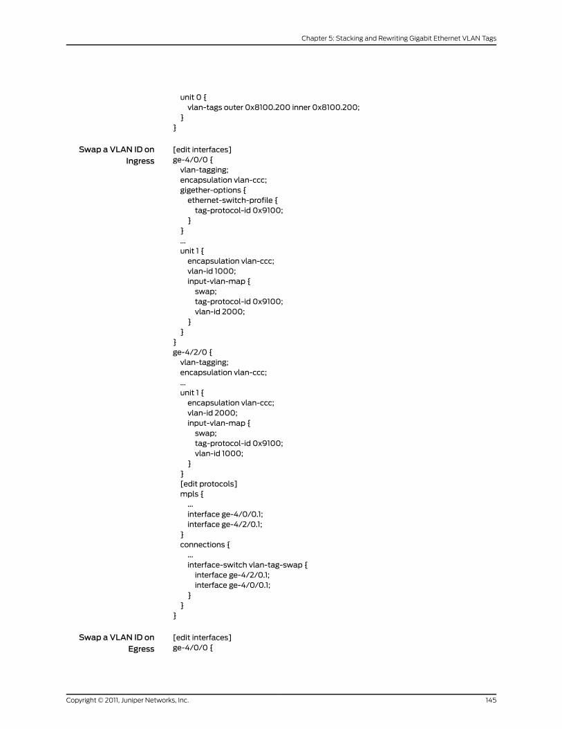
unit 0 {vlan-tags outer 0x8100.200 inner 0x8100.200;
}}
Swap a VLAN ID onIngress
[edit interfaces]ge-4/0/0 {vlan-tagging;encapsulation vlan-ccc;gigether-options {ethernet-switch-profile {tag-protocol-id 0x9100;
}}...unit 1 {encapsulation vlan-ccc;vlan-id 1000;input-vlan-map {swap;tag-protocol-id 0x9100;vlan-id 2000;
}}
}ge-4/2/0 {vlan-tagging;encapsulation vlan-ccc;...unit 1 {encapsulation vlan-ccc;vlan-id 2000;input-vlan-map {swap;tag-protocol-id 0x9100;vlan-id 1000;
}}[edit protocols]mpls {...interface ge-4/0/0.1;interface ge-4/2/0.1;
}connections {...interface-switch vlan-tag-swap {interface ge-4/2/0.1;interface ge-4/0/0.1;
}}
}
Swap a VLAN ID onEgress
[edit interfaces]ge-4/0/0 {
145Copyright © 2011, Juniper Networks, Inc.
Chapter 5: Stacking and Rewriting Gigabit Ethernet VLAN Tags

vlan-tagging;encapsulation vlan-ccc;...unit 1 {encapsulation vlan-ccc;vlan-id 1000;
}}ge-4/2/0 {vlan-tagging;encapsulation vlan-ccc;gigether-options {ethernet-switch-profile {tag-protocol-id 0x8800;
}}...unit 1 {encapsulation vlan-ccc;vlan-id 2000;output-vlan-map {swap;tag-protocol-id 0x8800;
}}
}[edit protocols]mpls {...interface ge-4/0/0.1;interface ge-4/2/0.1;
}connections {...interface-switch vlan-tag-swap {interface ge-4/2/0.1;interface ge-4/0/0.1;
}}
Swap a VLAN ID onBoth Ingress and
Egress
[edit interfaces]ge-4/0/0 {vlan-tagging;encapsulation vlan-ccc;gigether-options {ethernet-switch-profile {tag-protocol-id [ 0x8800 0x9100 ];
}}...unit 1 {encapsulation vlan-ccc;vlan-id 1000;input-vlan-map {swap;tag-protocol-id 0x9100;
Copyright © 2011, Juniper Networks, Inc.146
Junos®
OS 11.4 Ethernet Interfaces Configuration Guide

vlan-id 2000;}
}}ge-4/2/0 {vlan-tagging;encapsulation vlan-ccc;gigether-options {ethernet-switch-profile {tag-protocol-id [ 0x8800 0x9100 ];
}}unit 1 {encapsulation vlan-ccc;vlan-id 2000;output-vlan-map {swap;tag-protocol-id 0x8800;
}}
}[edit protocols]mpls {...interface ge-4/0/0.1;interface ge-4/2/0.1;
}connections {...interface-switch vlan-tag-swap {interface ge-4/2/0.1;interface ge-4/0/0.1;
}}
Swap the Outer VLANTag and Push a New
[edit interfaces]ge-1/1/0 {unit 1 {VLAN Tag on Ingress;vlan-id 200;Pop the Outer VLANinput-vlan-map {
Tag and Swap theswap-push;
Inner VLAN Tag onEgress
tag-protocol-id 0x9100;vlan-id 400;inner-tag-protocol-id 0x9100;inner-vlan-id 500;
}output-vlan-map {pop-swap;inner-tag-protocol-id 0x9100;
}}
}
SwapaTPIDandVLANID Pair for Both VLAN
[edit interfaces]ge-1/1/0 {
147Copyright © 2011, Juniper Networks, Inc.
Chapter 5: Stacking and Rewriting Gigabit Ethernet VLAN Tags

unit 0 {Tags on Ingress andonEgress vlan-tags {
inner 0x9100.425;outer 0x9200.525;
}input-vlan-map {swap-swap;tag-protocol-id 0x9100;vlan-id 400;inner-tag-protocol-id 0x9100;inner-vlan-id 500;
}output-vlan-map {swap-swap;tag-protocol-id 0x9200;inner-tag-protocol-id 0x9100;
}}
}
Pop the Outer VLANTag and Swap the
[edit interfaces]ge-1/1/0 {unit 0 {Inner VLAN Tag onvlan-tags {Ingress; Swap theinner 0x9100.425;
Outer VLAN Tag andouter 0x9200.525;
Push a NewVLAN Tagon Egress
}input-vlan-map {pop-swap;tag-protocol-id 0x9100;vlan-id 400;
}output-vlan-map{swap-push;tag-protocol-id 0x9200;inner-tag-protocol-id 0x9100;
}}
}
Pop a TPID and VLANIDPairon Ingress;Push
[edit interfaces]ge-1/1/0 {unit 0 {a VLAN ID and TPID
Pair on Egress vlan-tags {inner 0x9100.425;outer 0x9200.525;
}input-vlan-map{pop-pop;
}output-vlan-map {push-push;tag-protocol-id 0x9200;inner-tag-protocol-id 0x9100;
}
Copyright © 2011, Juniper Networks, Inc.148
Junos®
OS 11.4 Ethernet Interfaces Configuration Guide

}}
Pop an Outer VLANTag to Connect an
[edit interfaces]ge-1/1/0 {vlan-tagging;Untagged VPLSencapsulation extended-vlan-vpls;Interface to Tagged
VPLS Interfacesunit 0 {vlan-id 0;input-vlan-map {push;vlan-id 0;
}output-vlan-map pop;family vpls;
}}
RelatedDocumentation
• input-vlan-map on page 461
• output-vlan-map
• inner-tag-protocol-id on page 457
• inner-vlan-id on page 458
• pop on page 493
• pop-pop on page 493
• pop-swap on page 494
• push on page 502
• push-push on page 503
• swap on page 512
• swap-push on page 512
• swap-swap on page 513
• unit on page 520
• Junos OS Ethernet Interfaces Configuration Guide
149Copyright © 2011, Juniper Networks, Inc.
Chapter 5: Stacking and Rewriting Gigabit Ethernet VLAN Tags

Copyright © 2011, Juniper Networks, Inc.150
Junos®
OS 11.4 Ethernet Interfaces Configuration Guide

CHAPTER 6
Configuring Layer 2 Bridging Interfaces
• Layer 2 Bridging Interfaces Overview on page 151
• Configuring Layer 2 Bridging Interfaces on page 151
Layer 2 Bridging Interfaces Overview
Bridging operates at Layer 2 of the OSI reference model while routing operates at Layer
3. A set of logical ports configured for bridging can be said to constitute a bridging domain.
A bridging domain can be created by configuring a routing instance and specifying the
instance-type as bridge.
Integrated routing and bridging (IRB) is the ability to:
• Route a packet if the destination MAC address is the MAC address of the router and
the packet ethertype is IPv4, IPv6, or MPLS.
• Switch all multicast and broadcast packets within a bridging domain at layer 2.
• Route a copy of the packet if the destination MAC address is a multicast address and
the ethertype is IPv4 or IPv6.
• Switch all other unicast packets at Layer 2.
• Handle supported Layer 2 control packets such as STP and LACP.
• Handle supported Layer 3 control packets such as OSPF and RIP.
RelatedDocumentation
Configuring Layer 2 Bridging Interfaces on page 151•
• Junos OS Ethernet Interfaces Configuration Guide
Configuring Layer 2 Bridging Interfaces
You can configure an IRB logical interface at the [edit interfaces ge-fpc /pic/port unit
logical-unit-number] hierarchy level:
[edit interfaces ge-fpc/pic/port]unit logical-unit-number {}
151Copyright © 2011, Juniper Networks, Inc.
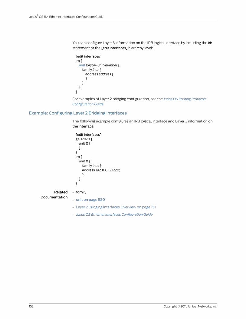
You can configure Layer 3 information on the IRB logical interface by including the irb
statement at the [edit interfaces] hierarchy level:
[edit interfaces]irb {unit logical-unit-number {family inet {address address {}
}}
}
For examples of Layer 2 bridging configuration, see the Junos OS Routing Protocols
Configuration Guide.
Example: Configuring Layer 2 Bridging Interfaces
The following example configures an IRB logical interface and Layer 3 information on
the interface.
[edit interfaces]ge-1/0/0 {unit 0 {}
}irb {unit 0 {family inet {address 192.168.12.1/28;}
}}
RelatedDocumentation
• family
• unit on page 520
• Layer 2 Bridging Interfaces Overview on page 151
• Junos OS Ethernet Interfaces Configuration Guide
Copyright © 2011, Juniper Networks, Inc.152
Junos®
OS 11.4 Ethernet Interfaces Configuration Guide
CHAPTER 7
Configuring Link Layer Discovery Protocol
• LLDP Overview on page 153
• Configuring LLDP on page 154
• Tracing LLDP Operations on page 156
• Example: Configuring LLDP on page 157
LLDPOverview
The Link Layer Discovery Protocol (LLDP) is an industry-standard, vendor-neutral method
to allow networked devices to advertise capabilities, identity, and other information onto
a LAN. The Layer 2 protocol, detailed in IEEE 802.1AB-2005, replaces several proprietary
protocols implemented by individual vendors for their equipment.
LLDP allows network devices that operate at the lower layers of a protocol stack (such
as Layer 2 bridges and switches) to learn some of the capabilities and characteristics of
LAN devices available to higher layer protocols, such as IP addresses. The information
gathered through LLDP operation is stored in a network device and is queried with SNMP.
Topology information can also be gathered from this database.
Some of the information that can be gathered by LLDP (only minimal information is
mandatory) is:
• System name and description
• Port name and description
• VLAN name and identifier
• IP network management address
• Capabilities of the device (for example, switch, router, or server)
• MAC address and physical layer information
• Power information
• Link aggregation information
NOTE: LLDPmedia endpoint discovery (LLDP-MED) is not supported on TSeries routers.
153Copyright © 2011, Juniper Networks, Inc.

LLDP frames are sent at fixed intervals on each port that runs LLDP. LLDP protocol data
units (LLDP PDUs) are sent inside Ethernet frames and identified by their destination
Media Access Control (MAC) address (01:80:C2:00:00:0E) and Ethertype (0x88CC).
Mandatory information supplied by LLDP is chassis ID, port ID, and a time-to-live value
for this information.
LLDP is a powerful way to allow Layer 2 devices to gather details about other
network-attached devices.
RelatedDocumentation
Configuring LLDP on page 154•
• Tracing LLDP Operations on page 156
• Example: Configuring LLDP on page 157
• LLDP Operational Mode Commands
Configuring LLDP
You configure LLDP by including the lldp statement and associated parameters at the
[edit protocols] hierarchy level. The complete set of LLDP statements follows:
lldp {advertisement-interval seconds;disable;hold-multiplier number;interface (all | interface-name) {disable;
}lldp-configuration-notification-interval seconds;ptopo-configuration-maximum-hold-time seconds;ptopo-configuration-trap-interval seconds;traceoptions {file filename <files number> <size size> <world-readable | no-world-readable>;flag flag <flag-modifier> <disable>;
}transmit-delay seconds
}
The following statements have default values:
• advertisement-interval—The default value is 30 seconds. The allowable range is from 5
through 32768 seconds.
• hold-multiplier—The default values is 4. The allowable range is from 2 through 10.
• ptopo-configuration-maximum-hold-time—The default value is 300 seconds. The
allowable range is from 1 through 2147483647 seconds.
• transmit-delay—The default values is 2 seconds. The allowable range is from 1 through
8192 seconds.
Copyright © 2011, Juniper Networks, Inc.154
Junos®
OS 11.4 Ethernet Interfaces Configuration Guide

The following statements must be explicitly configured:
• lldp-configuration-notification-interval—The allowable range is from 0 through
3600 seconds. There is no default value.
• ptopo-configuration-trap-interval—The allowable range is from 1 through
2147483647 seconds. There is no default value.
To disable LLDP on all or a particular interface, include the interfaces statement at the
[edit protocols lldp] hierarchy level:
interface (all | interface-name) {disable;
}
To disable LLDP on all interfaces, use the all option. To disable LLDP on a particular
interface, include the disable statement with the interface name.
To configure LLDP on a T Series router within a TX Matrix, you must specify the interface
name in the LLDP configuration for the TX Matrix. For information about interface names
for TX Matrix routers, see TX Matrix Router Chassis and Interface Names. For information
about FPC numbering, see Routing Matrix with a TX Matrix Router FPC Numbering
NOTE: The interface-namemust be the physical interface (for example,
ge-1/0/0) and not a logical interface (unit).
The advertisement interval determines the frequency that an LLDP interface sends LLDP
advertisement frames. The default value is 30 seconds. The allowable range is from 5
through 32768 seconds. You adjust this parameter by including theadvertisement-interval
statement at the [edit protocols lldp] hierarchy level.
The hold multiplier determines the multiplier to apply to the advertisement interval. The
resulting value in seconds is used to cache learned LLDP information before discard. The
default value is 4. When used with the default advertisement interval value of 30 seconds,
this makes the default cache lifetime 120 seconds. The allowable range of the hold
multiplier is from 2 through 10. You adjust this parameter by including the hold-multiplier
statement at the [edit protocols lldp] hierarchy level.
The transmit delay determines the delay between any two consecutive LLDP
advertisement frames. The default value is 2 seconds. The allowable range is from 1
through 8192 seconds. You adjust this parameter by including the transmit-delay
statement at the [edit protocols lldp] hierarchy level.
The physical topology configuration maximum hold time determines the time interval
for which an agent device maintains physical topology database entries. The default
value is 300 seconds. The allowable range is from 1 through 2147483647 seconds. You
adjust this parameter by including theptopo-configuration-maximum-hold-timestatement
at the [edit protocols lldp] hierarchy level.
The LLDP configuration notification interval determines the period for which trap
notifications are sent to the SNMP Master Agent when changes occur in the database
155Copyright © 2011, Juniper Networks, Inc.
Chapter 7: Configuring Link Layer Discovery Protocol
of LLDP information. This capability is disabled by default. The allowable range is from 0
(disabled) through 3600 seconds. You adjust this parameter by including the
lldp-configuration-notification-interval statement at the [edit protocols lldp] hierarchy
level.
The physical topology configuration trap interval determines the period for which trap
notifications are sent to the SNMP Master Agent when changes occur in the global
physical topology statistics. This capability is disabled by default. The allowable range
is from 0 (disabled) through 3600 seconds. The LLDP agent sends traps to the SNMP
Master Agent if this interval has a value greater than 0 and there is any change during
the lldp-configuration-notification-interval trap interval. You adjust this parameter by
including the ptopo-configuration-trap-interval statement at the [edit protocols lldp]
hierarchy level.
RelatedDocumentation
LLDP Overview on page 153•
• Tracing LLDP Operations on page 156
• Example: Configuring LLDP on page 157
• LLDP Operational Mode Commands
• TX Matrix Router Chassis and Interface Names
• Miscellaneous Commands for a Routing Matrix with a TX Matrix Router
Tracing LLDPOperations
To trace LLDP operational traffic, you can specify options in the global traceoptionsstatement included at the [edit routing-options] hierarchy level, and you can specifyLLDP-specific options by including the traceoptions statement:
traceoptions {file filename <files number> <size size> <world-readable | no-world-readable>;flag flag <flag-modifier> <disable>;
}
You can include this statement at the following hierarchy levels:
• [edit protocols lldp]
• [edit routing-instances routing-instance-name protocols lldp]
You can specify the following LLDP-specific options in the LLDP traceoptions statement:
• all—Trace all operations.
• config—Log configuration events.
• interface—Trace interface update events.
• protocol—Trace protocol information.
• rtsock—Trace real-time socket events.
• vlan—Trace VLAN update events.
Copyright © 2011, Juniper Networks, Inc.156
Junos®
OS 11.4 Ethernet Interfaces Configuration Guide
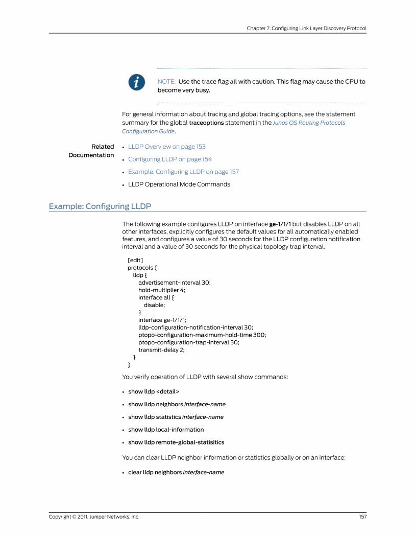
NOTE: Use the trace flag allwith caution. This flagmay cause the CPU to
become very busy.
For general information about tracing and global tracing options, see the statement
summary for the global traceoptions statement in the Junos OS Routing Protocols
Configuration Guide.
RelatedDocumentation
LLDP Overview on page 153•
• Configuring LLDP on page 154
• Example: Configuring LLDP on page 157
• LLDP Operational Mode Commands
Example: Configuring LLDP
The following example configures LLDP on interface ge-1/1/1 but disables LLDP on allother interfaces, explicitly configures the default values for all automatically enabledfeatures, and configures a value of 30 seconds for the LLDP configuration notificationinterval and a value of 30 seconds for the physical topology trap interval.
[edit]protocols {lldp {advertisement-interval 30;hold-multiplier 4;interface all {disable;
}interface ge-1/1/1;lldp-configuration-notification-interval 30;ptopo-configuration-maximum-hold-time 300;ptopo-configuration-trap-interval 30;transmit-delay 2;
}}
You verify operation of LLDP with several show commands:
• show lldp <detail>
• show lldp neighbors interface-name
• show lldp statistics interface-name
• show lldp local-information
• show lldp remote-global-statisitics
You can clear LLDP neighbor information or statistics globally or on an interface:
• clear lldp neighbors interface-name
157Copyright © 2011, Juniper Networks, Inc.
Chapter 7: Configuring Link Layer Discovery Protocol

• clear lldp statistics interface-name
You can display basic information about LLDP with the show lldp detail command:
user@host> show lldp detailLLDP : EnabledAdvertisement interval : 30 Second(s)Transmit delay : 2 Second(s)Hold timer : 4 Second(s)Notification interval : 30 Second(s)Config Trap Interval : 300 Second(s)Connection Hold timer : 60 Second(s)
Interface LLDP Neighbor countge-1/1/1 Enabled 0
LLDP basic TLVs supported: Chassis identifier, Port identifier, Port description, System name, System description, System capabilities, Management address.
LLDP 802 TLVs supported: Link aggregation, Maximum frame size, MAC/PHY Configuration/Status, Port VLAN ID, Port VLAN name.
For more details about the output of these commands, see the JunosOSRoutingProtocols
and Policies Command Reference.
RelatedDocumentation
• LLDP Overview on page 153
• Configuring LLDP on page 154
• Tracing LLDP Operations on page 156
• LLDP Operational Mode Commands
Copyright © 2011, Juniper Networks, Inc.158
Junos®
OS 11.4 Ethernet Interfaces Configuration Guide
CHAPTER 8
Configuring TCC and Layer 2.5 Switching
• TCC and Layer 2.5 Switching Overview on page 159
• Configuring VLAN TCC Encapsulation on page 159
• Configuring Ethernet TCC on page 161
TCC and Layer 2.5 Switching Overview
Translational cross-connect (TCC) is a switching concept that allows you to forward
traffic between a variety of Layer 2 protocols or circuits. It is similar to its predecessor,
CCC. However, while CCC requires the same Layer 2 encapsulations on both sides of a
router (such as Point-to-Point Protocol [PPP] or Frame Relay-to-Frame Relay), TCC
lets you connect different types of Layer 2 protocols interchangeably. With TCC,
combinations such as PPP-to-ATM and Ethernet-to-Frame Relay cross-connections are
possible.
RelatedDocumentation
Configuring VLAN TCC Encapsulation on page 159•
• Configuring Ethernet TCC on page 161
• Junos OS Ethernet Interfaces Configuration Guide
Configuring VLAN TCC Encapsulation
VLAN TCC encapsulation allows circuits to have different media on either side of the
forwarding path. VLAN TCC encapsulation supports TPID 0x8100 only. You must include
configuration statements at the logical and physical interface hierarchy levels.
To configure VLAN TCC encapsulation, include the encapsulation statement and specify
the vlan-tcc option:
[edit interfaces interface-name unit logical-unit-number]encapsulation vlan-tcc;
You can include this statement at the following hierarchy levels:
• [edit interfaces interface-name unit logical-unit-number ]
• [edit logical-systems logical-system-name interfaces interface-name unit
logical-unit-number]
159Copyright © 2011, Juniper Networks, Inc.
Additionally, configure the logical interface by including theproxyand remote statements:
proxy {inet-address;
}remote {(inet-address | mac-address);
}
You can include these statements at the following hierarchy levels:
• [edit interfaces interface-name unit logical-unit-number family tcc]
• [edit logical-systems logical-system-name interfaces interface-name unit
logical-unit-number family tcc]
The proxy address is the IP address of the non-Ethernet TCC neighbor for which the TCC
router is acting as a proxy.
The remote address is the IP or MAC address of the remote router. The remote statement
provides ARP capability from the TCC switching router to the Ethernet neighbor. The
MAC address is the physical Layer 2 address of the Ethernet neighbor.
When VLAN TCC encapsulation is configured on the logical interface, you also must
specify flexible Ethernet services on the physical interface. To specify flexible Ethernet
services, include the encapsulation statement at the [edit interfaces interface-name]
hierarchy level and specify the flexible-ethernet-services option:
[edit interfaces interface-name]encapsulation flexible-ethernet-services;
Extended VLAN TCC encapsulation supports TPIDs 0x8100 and 0x9901. Extended VLAN
TCC is specified at the physical interface level. When configured, all units on that interface
must use VLAN TCC encapsulation, and no explicit configuration is needed on logical
interfaces.
One-port Gigabit Ethernet, 2-port Gigabit Ethernet, and 4-port Fast Ethernet PICs with
VLAN tagging enabled can use VLAN TCC encapsulation. To configure the encapsulation
on a physical interface, include the encapsulation statement at the [edit interfaces
interface-name] hierarchy level and specify the extended-vlan-tcc option:
[edit interfaces interface-name]encapsulation extended-vlan-tcc;
For VLAN TCC encapsulation, all VLAN IDs from 1 through 1024 are valid. VLAN ID 0 is
reserved for tagging the priority of frames.
Extended VLAN TCC is not supported on 4-port Gigabit Ethernet PICs.
RelatedDocumentation
encapsulation•
• remote
• proxy
• TCC and Layer 2.5 Switching Overview on page 159
Copyright © 2011, Juniper Networks, Inc.160
Junos®
OS 11.4 Ethernet Interfaces Configuration Guide

• Configuring Ethernet TCC on page 161
• Junos OS Ethernet Interfaces Configuration Guide
Configuring Ethernet TCC
For Layer 2.5 virtual private networks (VPNs) using an Ethernet interface as the TCC
router, you can configure an Ethernet TCC.
To configure an Ethernet TCC, include the encapsulation statement and specify the
ethernet-tcc option at the [edit interfaces interface-name] hierarchy level:
[edit interfaces interface-name]encapsulation ethernet-tcc;
For Ethernet TCC encapsulation, you must also configure the logical interface by including
the proxy and remote statements:
proxy {inet-address;
}remote {(inet-address | mac-address);
}
You can include these statements at the following hierarchy levels:
• [edit interfaces interface-name unit logical-unit-number family tcc]
• [edit logical-systems logical-system-name interfaces interface-name unit
logical-unit-number family tcc]
The proxy address is the IP address of the non-Ethernet TCC neighbor for which the TCC
router is acting as a proxy.
The remote address is the IP or MAC address of the remote router. The remote statement
provides ARP capability from the TCC switching router to the Ethernet neighbor. The
MAC address is the physical Layer 2 address of the Ethernet neighbor.
Ethernet TCC is supported on interfaces that carry IPv4 traffic only. For 8-port, 12-port,
and 48-port Fast Ethernet PICs, TCC and extended VLAN CCC are not supported. For
4-port Gigabit Ethernet PICs, extended VLAN CCC and extended VLAN TCC are not
supported.
Example: Configuring an Ethernet TCC or Extended VLAN TCC
Configure a full-duplex Layer 2.5 translational cross-connect between Router A and
Router C, using a Juniper Networks router, Router B, as the TCC interface. Ethernet TCC
encapsulation provides an Ethernet wide area circuit for interconnecting IP traffic. (See
the topology in Figure 15 on page 162.)
The Router A-to-Router B circuit is PPP, and the Router B-to-Router C circuit accepts
packets carrying standard TPID values.
161Copyright © 2011, Juniper Networks, Inc.
Chapter 8: Configuring TCC and Layer 2.5 Switching

If traffic flows from Router A to Router C, the Junos OS strips all PPP encapsulation data
from incoming packets and adds Ethernet encapsulation data before forwarding the
packets. If traffic flows from Router C to Router A, the Junos OS strips all Ethernet
encapsulation data from incoming packets and adds PPP encapsulation data before
forwarding the packets.
Figure 15: Topology of Layer 2.5 Translational Cross-Connect
On Router B interfaces
Configure a full-duplex Layer 2.5 translational cross-connect between Router A and
Router C, using a Juniper Networks router, Router B, as the TCC interface. Extended VLAN
TCC encapsulation provides an Ethernet wide area circuit for interconnecting IP traffic.
(See the topology in Figure 15 on page 162.)
Configuring anExtended VLAN TCC
The Router A-to-Router B circuit is PPP, and the Router B-to-Router C circuit is Ethernetwith VLAN tagging enabled.
On Router B interfacesge-0/0/0 {vlan-tagging;
encapsulation extended-vlan-tcc;unit 0 {vlan-id 1;family tcc {proxy {inet-address 10.10.10.3;
}remote {inet-address 10.10.10.2;
}}
}
RelatedDocumentation
• encapsulation
• remote
• proxy
• TCC and Layer 2.5 Switching Overview on page 159
• Configuring VLAN TCC Encapsulation on page 159
• Junos OS Ethernet Interfaces Configuration Guide
Copyright © 2011, Juniper Networks, Inc.162
Junos®
OS 11.4 Ethernet Interfaces Configuration Guide

CHAPTER 9
Configuring Static ARP Table Entries
• Static ARP Table Entries Overview on page 163
• Configuring Static ARP Table Entries on page 163
Static ARP Table Entries Overview
For Fast Ethernet, Gigabit Ethernet, Tri-Rate Ethernet copper, and 10-Gigabit Ethernet
interfaces, you can configure static ARP table entries, defining mappings between IP and
MAC addresses.
RelatedDocumentation
Configuring Static ARP Table Entries on page 163•
• Junos OS Ethernet Interfaces Configuration Guide
Configuring Static ARP Table Entries
To configure static ARP table entries, include the arp statement:
arp ip-address (mac | multicast-mac)mac-address <publish>;
You can include this statement at the following hierarchy levels:
• [edit interfaces interface-name unit logical-unit-number family inet address address]
• [edit logical-systems logical-system-name interfaces interface-name unit
logical-unit-number family inet address address]
The IP address that you specify must be part of the subnet defined in the enclosing
address statement.
To associate a multicast MAC address with a unicast IP address, include themulticast-mac
statement.
Specify the MAC address as six hexadecimal bytes in one of the following formats:
nnnn.nnnn.nnnn or nn:nn:nn:nn:nn:nn; for example, 0011.2233.4455 or 00:11:22:33:44:55.
For unicast MAC addresses only, if you include the publish option, the router or switch
replies to proxy ARP requests.
163Copyright © 2011, Juniper Networks, Inc.

NOTE: By default, an ARP policer is installed that is shared among all theEthernet interfaces on which you have configured the family inet statement.
By including the arp statement at the [edit interfaces interface-name unit
logical-unit-number family inetpolicer]hierarchy level, youcanapplyaspecific
ARP-packet policer to an interface. This feature is not available on EX Seriesswitches.
When you need to conserve IP addresses, you can configure an Ethernetinterface tobeunnumberedby including theunnumbered-address statement
at the [edit interfaces interface-name unit logical-unit-number family inet]
hierarchy level.
NOTE: The Junos OS supports the IPv6 static neighbor discovery cacheentries, similar to the static ARP entries in IPv4.
Example: Configuring Static ARP Table Entries
Configure two static ARP table entries on the router or switch’s management interface:
[edit interfaces]fxp0 {unit 0 {family inet {address 10.10.0.11/24 {arp 10.10.0.99mac 0001.0002.0003;arp 10.10.0.101 mac 00:11:22:33:44:55 publish;
}}
}}
RelatedDocumentation
• Management Ethernet Interface Overview on page 333
• Applying Policers
• Configuring an Unnumbered Interface
• Junos OS Ethernet Interfaces Configuration Guide
Copyright © 2011, Juniper Networks, Inc.164
Junos®
OS 11.4 Ethernet Interfaces Configuration Guide
CHAPTER 10
Configuring Restricted and UnrestrictedProxy ARP
• Restricted and Unrestricted Proxy ARP Overview on page 165
• Configuring Restricted and Unrestricted Proxy ARP on page 167
Restricted and Unrestricted Proxy ARPOverview
By default, the Junos OS responds to an Address Resolution Protocol (ARP) request only
if the destination address of the ARP request is local to the incoming interface.
For Ethernet Interfaces, you can configure the router or switches to proxy-reply to the
ARP requests using the restricted or unrestricted proxy ARP configuration.
You might want to configure restricted or unrestricted proxy ARP for routers that act as
provider edge (PE) devices in Ethernet Layer 2 LAN switching domains.
Restricted Proxy ARP
Restricted proxy ARP enables the router or switch to respond to the ARP requests in
which the physical networks of the source and target are not the same and the router or
switch has an active route to the target address in the ARP request. The router does not
reply if the target address is on the same subnet and the same interface as the ARP
requestor.
Unrestricted Proxy ARP
Unrestricted proxy ARP enables the router or switch to respond to any ARP request, on
condition that the router has an active route to the destination address of the ARP request.
The route is not limited to the incoming interface of the request, nor is it required to be a
direct route.
WARNING: If you configure unrestricted proxy ARP, the proxy router repliesto ARP requests for the target IP address on the same interface as theincoming ARP request. This behavior is appropriate for cable modemtermination system (CMTS) environments, but might cause Layer 2reachability problems if you enable unrestricted proxy ARP in otherenvironments.
165Copyright © 2011, Juniper Networks, Inc.

When an IP client broadcasts the ARP request across the Ethernet wire, the end node
with the correct IP address responds to the ARP request and provides the correct MAC
address. If the unrestricted proxy ARP feature is enabled, the router response is redundant
and might fool the IP client into determining that the destination MAC address within its
own subnet is the same as the address of the router.
NOTE: While the destination address can be remote, the source address ofthe ARP request must be on the same subnet as the interface upon whichthe ARP request is received. For security reasons, this rule applies to bothunrestricted and restricted proxy ARP.
Topology Considerations for Unrestricted Proxy ARP
In most situations, you should not configure the router to perform unrestricted proxy ARP.
Do so only for special situations, such as when cable modems are used. Figure 16 on
page 166 and Figure 17 on page 167 show examples of situations in which you might want
to configure unrestricted proxy ARP.
In Figure 16 on page 166, the edge device is not running any IP protocols. In this case, you
configure the core router to perform unrestricted proxy ARP. The edge device is the client
of the proxy.
In Figure 17 on page 167, the Broadband Remote Access Server (B-RAS) routers are not
running any IP protocols. In this case, you configure unrestricted proxy ARP on the B-RAS
interfaces. This allows the core device to behave as though it is directly connected to the
end users.
Figure 16: Edge Device Case for Unrestricted Proxy ARP
Copyright © 2011, Juniper Networks, Inc.166
Junos®
OS 11.4 Ethernet Interfaces Configuration Guide
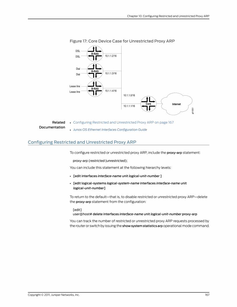
Figure 17: Core Device Case for Unrestricted Proxy ARP
RelatedDocumentation
Configuring Restricted and Unrestricted Proxy ARP on page 167•
• Junos OS Ethernet Interfaces Configuration Guide
Configuring Restricted and Unrestricted Proxy ARP
To configure restricted or unrestricted proxy ARP, include the proxy-arp statement:
proxy-arp (restricted |unrestricted);
You can include this statement at the following hierarchy levels:
• [edit interfaces interface-name unit logical-unit-number ]
• [edit logical-systems logical-system-name interfaces interface-name unit
logical-unit-number]
To return to the default—that is, to disable restricted or unrestricted proxy ARP—delete
the proxy-arp statement from the configuration:
[edit]user@host# delete interfaces interface-name unit logical-unit-number proxy-arp
You can track the number of restricted or unrestricted proxy ARP requests processed by
the router or switch by issuing the showsystemstatisticsarpoperational mode command.
167Copyright © 2011, Juniper Networks, Inc.
Chapter 10: Configuring Restricted and Unrestricted Proxy ARP

NOTE: When proxy ARP is enabled as default or unrestricted, the routerresponds to any ARP request as long as the router has an active route to thetarget address of the ARP request. This gratuitous ARP behavior can resultin an error when the receiving interface and target response interface are thesameand theenddevice (for example, aclient)performsaduplicateaddresscheck. To prevent this error, configure the router interface with theno-gratuitous-arp-reply statement. See “Configuring Gratuitous ARP” on
page 47 for information about how to disable responses to gratuitous ARPrequests.
RelatedDocumentation
• proxy-arp
• Restricted and Unrestricted Proxy ARP Overview on page 165
• Configuring Gratuitous ARP on page 47
• Junos OS Ethernet Interfaces Configuration Guide
Copyright © 2011, Juniper Networks, Inc.168
Junos®
OS 11.4 Ethernet Interfaces Configuration Guide
CHAPTER 11
Configuring MAC Address Validation onStatic Ethernet Interfaces
• MAC Address Validation on Static Ethernet Interfaces Overview on page 169
• Configuring MAC Address Validation on Static Ethernet Interfaces on page 170
• Disabling MAC Address Learning of Neighbors Through ARP or Neighbor Discovery for
IPv4 and IPv6 Neighbors on page 170
MACAddress Validation on Static Ethernet Interfaces Overview
MAC address validation enables the router to validate that received packets contain a
trusted IP source and an Ethernet MAC source address.
MAC address validation is supported on AE, Fast Ethernet, Gigabit Ethernet, and 10–Gigabit
Ethernet interfaces (with or without VLAN tagging) on MX Series routers only.
There are two types of MAC address validation that you can configure:
• Loose—Forwards packets when both the IP source address and the MAC source address
match one of the trusted address tuples.
Drops packets when the IP source address matches one of the trusted tuples, but the
MAC address does not support the MAC address of the tuple
Continues to forward packets when the source address of the incoming packet does
not match any of the trusted IP addresses.
• Strict—Forwards packets when both the IP source address and the MAC source address
match one of the trusted address tuples.
Drops packets when the MAC address does not match the tuple's MAC source address,
or when IP source address of the incoming packet does not match any of the trusted
IP addresses.
RelatedDocumentation
Configuring MAC Address Validation on Static Ethernet Interfaces on page 170•
• Disabling MAC Address Learning of Neighbors Through ARP or Neighbor Discovery for
IPv4 and IPv6 Neighbors on page 170
• Junos OS Ethernet Interfaces Configuration Guide
169Copyright © 2011, Juniper Networks, Inc.

ConfiguringMACAddress Validation on Static Ethernet Interfaces
To configure MAC address validation on static Ethernet interfaces, include the
mac-validate (loose | strict) statement in the [edit interfaces interface-name unit
logical-unit-number family family] hierarchy:
[edit interfaces interface-name unit logical-unit-number family family]mac-validate (loose | strict);
Example of Strict MAC Validation on a Static Ethernet Interface
This example shows strict MAC address validation on a static Ethernet interface without
VLAN tagging.
[edit interfaces]ge-2/1/9 {unit 0 {proxy-arp;family inet {mac-validate strict;address 88.22.100.1/24 {arp 88.22.100.3mac 00:00:58:16:64:03;
}}
}}
RelatedDocumentation
family•
• mac-validate
• Junos OS Ethernet Interfaces Configuration Guide
DisablingMACAddress Learning of Neighbors Through ARP or Neighbor Discovery forIPv4 and IPv6 Neighbors
The Junos OS provides the no-neighbor-learn configuration statement at the [edit
interfaces interface-name unit interface-unit-number family inet] and [edit interfaces
interface-name unit interface-unit-number family inet6] hierarchy levels.
To disable ARP address learning by not sending arp-requests and not learning from ARP
replies for IPv4 neigbors, include the no-neighbor-learn statement at the [edit interfaces
interface-name unit interface-unit-number family inet] hierarchy level:
[edit interfaces interface-name unit interface-unit-number family inet]no-neighbor-learn;
To disable neighbor discovery for IPv6 neighbors, include theno-neighbor-learn statement
at the [edit interfaces interface-nameunit logical-unit-number family inet6]hierarchy level:
[edit interfaces interface-name unit interface-unit-number family inet6]no-neighbor-learn;
Copyright © 2011, Juniper Networks, Inc.170
Junos®
OS 11.4 Ethernet Interfaces Configuration Guide

RelatedDocumentation
• Configuring the Junos OS ARP Learning and Aging Options for Mapping IPv4 Network
Addresses to MAC Addresses
• Junos OS Ethernet Interfaces Configuration Guide
171Copyright © 2011, Juniper Networks, Inc.
Chapter 11: Configuring MAC Address Validation on Static Ethernet Interfaces

Copyright © 2011, Juniper Networks, Inc.172
Junos®
OS 11.4 Ethernet Interfaces Configuration Guide

CHAPTER 12
Enabling Passive Monitoring on EthernetInterfaces
• Passive Monitoring on Ethernet Interfaces Overview on page 173
• Enabling Passive Monitoring on Ethernet Interfaces on page 175
Passive Monitoring on Ethernet Interfaces Overview
The Monitoring Services I and Monitoring Services II PICs are designed to enable IP services.
You can monitor IPv4 traffic if you have a Monitoring Services PIC installed in the router
with the following PICs:
• 10-port Gigabit Ethernet PIC with SFPs
• 4-port Gigabit Ethernet PIC with SFPs
• 2-port Gigabit Ethernet PIC with SFPs
• 1-port 10-Gigabit Ethernet PIC
NOTE: The PICs in the preceding list support only IPv4.
NOTE: I2.0 basedM120 routers and I3.0 basedM320 routers with the PICsin thepreceding list supportpassivemonitoringstartingwith JunosOSRelease9.5. Other M Series and T Series routers with the PICs listed above startedsupportingpassivemonitoringbefore JunosOSRelease7.3.Support for 1-port10-Gigabit Ethernet PIC with XENPAK on I2.0-basedM120 routers andI3.0-basedM320 routers was added in Junos OS Release 9.5.
• 4-port 10-Gigabit Ethernet LAN/WAN PIC with XFP (T640 and T1600) (supported on
both WAN-PHY and LAN-PHY modes for both IPv4 and IPv6 addresses)
The following interfaces support passive monitoring on the I3.0-based MX 240, MX 480,
and MX 960 routers, starting with Junos OS Release 8.5:
173Copyright © 2011, Juniper Networks, Inc.

• Type 2 MX FPCs
• Type 3 MX FPCs
• Gigabit Ethernet Enhanced DPC with SFP (DPCE-R-40GE-SFP)
• 4-port 10-Gigabit Ethernet Enhanced DPCs with XFP (DPCE-R-4XGE-XFP)
The following interfaces support passive monitoring on the Trio-based MX 240, MX 480,
and MX 960 routers:
• 10-Gigabit Ethernet MPC with SFP+
• 30-Gigabit Ethernet MPC
• 60-Gigabit Ethernet MPC
Passive monitoring is also supported on MX 80 routers with 10-Gigabit Ethernet MPC
with SFP+ and 30-Gigabit Ethernet MPC interfaces.
Interfaces configured on the following FPCs and PIC support IPv6 passive monitoring on
the T640 and T1600 routers:
• Enhanced Scaling FPC2
• Enhanced Scaling FPC3
• Enhanced Scaling FPC4
• Enhanced Scaling FPC4.1
• Enhanced II FPC1
• Enhanced II FPC2
• Enhanced II FPC3
• 4-port 10-Gigabit Ethernet LAN/WAN PIC with XFP (supported on both WAN-PHY
and LAN-PHY modes for both IPv4 and IPv6 addresses)
• Gigabit Ethernet PIC with SFP
• 10-Gigabit Ethernet PIC with XENPAK (T1600 router)
• SONET/SDH OC192/STM64 PIC (T1600 router)
• SONET/SDH OC192/STM64 PICs with XFP (T1600 router)
• SONET/SDH OC48c/STM16 PIC with SFP (T1600 router)
• SONET/SDH OC48/STM16 (Multi–Rate)
• SONET/SDH OC12/STM4 (Multi–Rate) PIC with SFP
• Type 1 SONET/SDH OC3/STM1 (Multi–Rate) PIC with SFP
NOTE: Unlike IPv4 passivemonitoring, IPv6 passivemonitoring is notsupported onMonitoring Services PICs. Youmust configure portmirroring toforward the packets from the passivemonitored ports to other interfaces.
Copyright © 2011, Juniper Networks, Inc.174
Junos®
OS 11.4 Ethernet Interfaces Configuration Guide

RelatedDocumentation
Passive Monitoring on Ethernet Interfaces Overview on page 173•
• Junos OS Ethernet Interfaces Configuration Guide
Enabling Passive Monitoring on Ethernet Interfaces
On Ethernet interfaces, enable packet flow monitoring by including the
passive-monitor-mode statement at the [edit interfaces interface-name ] hierarchy level:
[edit interfaces interface-name]passive-monitor-mode;
When you configure an interface in passive monitoring mode, the Packet Forwarding
Engine silently drops packets coming from that interface and destined to the router itself.
Passive monitoring mode also stops the Routing Engine from transmitting any packet
from that interface. Packets received from the monitored interface can be forwarded to
monitoring interfaces. If you include the passive-monitor-mode statement in the
configuration:
• Gigabit and Fast Ethernet interfaces can support both per-port passive monitoring and
per-VLAN passive monitoring. The destination MAC filter on the receive port of the
Ethernet interfaces is disabled.
• Ethernet encapsulation options are not allowed.
• Ethernet interfaces do not support the stacked-vlan-tagging statement for both IPv4
and IPv6 packets in passive monitor mode.
For IPv4 monitoring services interfaces, enable packet flow monitoring by including the
family statement at the [edit interfacesmo-fpc/pic/portunit logical-unit-number]hierarchy
level, specifying the inet option:
[edit interfacesmo-fpc/pic/port unit logical-unit-number]family inet;
For conformity with the cflowd record structure, you must include the
receive-options-packets and receive-ttl-exceeded statements at the [edit interfaces
mo-fpc/pic/port unit logical-unit-number family inet] hierarchy level:
[edit interfacesmo-fpc/pic/port unit logical-unit-number family inet]receive-options-packets;receive-ttl-exceeded;
IPv6 passive monitoring is not supported on monitoring services PICs. A user must
configure port mirroring to forward the packets from the passive monitored ports to other
interfaces. Interfaces configured on the following FPCs and PIC support IPv6 passive
monitoring on the T640 and T1600 routers:
• Enhanced Scaling FPC2
• Enhanced Scaling FPC3
• Enhanced II FPC1
• Enhanced II FPC2
175Copyright © 2011, Juniper Networks, Inc.
Chapter 12: Enabling Passive Monitoring on Ethernet Interfaces

• Enhanced II FPC3
• Enhanced Scaling FPC4
• Enhanced Scaling FPC4.1
• 4-port 10-Gigabit Ethernet LAN/WAN PIC with XFP (Supported on both WAN-PHY
and LAN-PHY modes for both IPv4 and IPv6 addresses)
• Gigabit Ethernet PIC with SFP
• 10-Gigabit Ethernet PIC with XENPAK (T1600 router)
• SONET/SDH OC192/STM64 PIC (T1600 router)
• SONET/SDH OC192/STM64 PICs with XFP (T1600 router)
• SONET/SDH OC48c/STM16 PIC with SFP (T1600 router)
• SONET/SDH OC48/STM16 (Multi-Rate)
• SONET/SDH OC12/STM4 (Multi–Rate) PIC with SFP
• Type 1 SONET/SDH OC3/STM1 (Multi–Rate) PIC with SFP
To configure port mirroring, include the port-mirroring statement at the [edit
forwarding-options] hierarchy level.
For the monitoring services interface, you can configure multiservice physical interface
properties. For more information, see Configuring Multiservice Physical Interface Properties
and the Junos OS Services Interfaces Configuration Guide.
RelatedDocumentation
• Passive Monitoring on Ethernet Interfaces Overview on page 173
• Configuring Multiservice Physical Interface Properties
• Junos OS Services Interfaces Configuration Guide
• Junos OS Ethernet Interfaces Configuration Guide
Copyright © 2011, Juniper Networks, Inc.176
Junos®
OS 11.4 Ethernet Interfaces Configuration Guide

CHAPTER 13
Configuring IEEE 802.1ag OAMConnectivity-Fault Management
• IEEE 802.1ag OAM Connectivity Fault Management Overview on page 177
• Creating the Maintenance Domain on page 179
• Configuring Maintenance Intermediate Points on page 181
• Creating a Maintenance Association on page 183
• Continuity Check Protocol on page 184
• Configuring a Maintenance Endpoint on page 186
• Configuring a Connectivity Fault Management Action Profile on page 191
• Configuring Linktrace Protocol in CFM on page 194
• Configuring Ethernet Local Management Interface on page 195
• Configuring Port Status TLV and Interface Status TLV on page 203
• Configuring MAC Flush Message Processing in CET Mode on page 215
• Configuring M120 and MX Series Routers for CCC Encapsulated Packets on page 218
• Configuring Rate Limiting of Ethernet OAM Messages on page 220
• Configuring 802.1ag Ethernet OAM for VPLS on page 223
• Configuring Unified ISSU for 802.1ag CFM on page 224
• Configuring CCM for Better Scalability on page 227
IEEE 802.1ag OAMConnectivity Fault Management Overview
Ethernet interfaces on M7i and M10i routers with the Enhanced CFEB (CFEB-E) and on
M120, M320, MX Series, and T Series routers support the IEEE 802.1ag standard for
Operation, Administration, and Management (OAM). The IEEE 802.1ag specification
provides for Ethernet connectivity fault management (CFM). The goal of CFM is to monitor
an Ethernet network that may comprise one or more service instances. Junos OS supports
IEEE 802.1ag connectivity fault management.
In Junos OS Release 9.3 and later, CFM also supports aggregated Ethernet interfaces.
On interfaces configured on Modular Port Concentrators (MPCs) and Modular Interface
Cards (MICs) on MX Series routers, CFM is not supported on untagged aggregated Ethernet
member links. MPCs and MICs do support CFM on untagged and tagged aggregated
177Copyright © 2011, Juniper Networks, Inc.
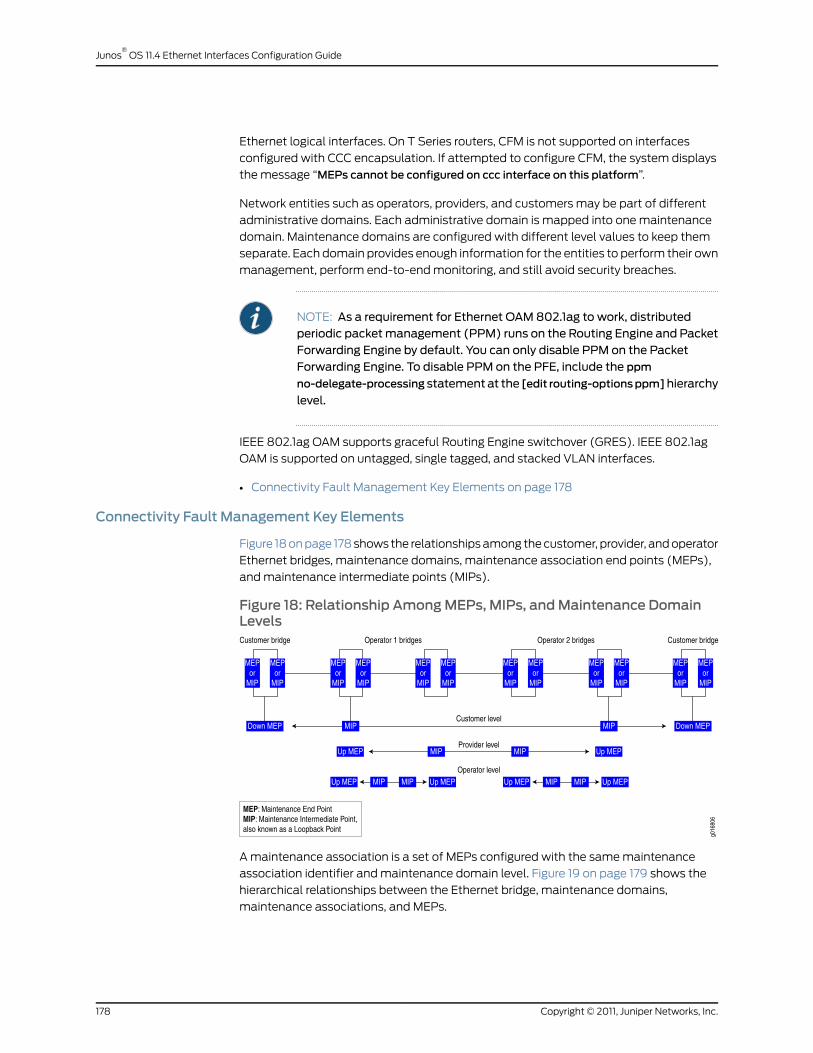
Ethernet logical interfaces. On T Series routers, CFM is not supported on interfaces
configured with CCC encapsulation. If attempted to configure CFM, the system displays
the message “MEPs cannot be configured on ccc interface on this platform”.
Network entities such as operators, providers, and customers may be part of different
administrative domains. Each administrative domain is mapped into one maintenance
domain. Maintenance domains are configured with different level values to keep them
separate. Each domain provides enough information for the entities to perform their own
management, perform end-to-end monitoring, and still avoid security breaches.
NOTE: As a requirement for Ethernet OAM 802.1ag to work, distributedperiodic packetmanagement (PPM) runs on the Routing Engine and PacketForwarding Engine by default. You can only disable PPM on the PacketForwarding Engine. To disable PPM on the PFE, include the ppm
no-delegate-processing statementat the [edit routing-optionsppm]hierarchy
level.
IEEE 802.1ag OAM supports graceful Routing Engine switchover (GRES). IEEE 802.1ag
OAM is supported on untagged, single tagged, and stacked VLAN interfaces.
• Connectivity Fault Management Key Elements on page 178
Connectivity Fault Management Key Elements
Figure 18 on page 178 shows the relationships among the customer, provider, and operator
Ethernet bridges, maintenance domains, maintenance association end points (MEPs),
and maintenance intermediate points (MIPs).
Figure 18: Relationship AmongMEPs, MIPs, andMaintenance DomainLevels
A maintenance association is a set of MEPs configured with the same maintenance
association identifier and maintenance domain level. Figure 19 on page 179 shows the
hierarchical relationships between the Ethernet bridge, maintenance domains,
maintenance associations, and MEPs.
Copyright © 2011, Juniper Networks, Inc.178
Junos®
OS 11.4 Ethernet Interfaces Configuration Guide

Figure 19: Relationship Among Bridges, Maintenance Domains,Maintenance Associations, andMEPs
RelatedDocumentation
connectivity-fault-management•
• Creating the Maintenance Domain on page 179
• Configuring Maintenance Intermediate Points on page 181
• Creating a Maintenance Association on page 183
• Continuity Check Protocol on page 184
• Configuring a Maintenance Endpoint on page 186
• Configuring a Connectivity Fault Management Action Profile on page 191
• Configuring Linktrace Protocol in CFM on page 194
• Configuring Ethernet Local Management Interface on page 195
• Configuring Port Status TLV and Interface Status TLV on page 203
• Configuring MAC Flush Message Processing in CET Mode on page 215
• Configuring M120 and MX Series Routers for CCC Encapsulated Packets on page 218
• Configuring Rate Limiting of Ethernet OAM Messages on page 220
• Configuring 802.1ag Ethernet OAM for VPLS on page 223
• Junos OS Ethernet Interfaces Configuration Guide
Creating theMaintenance Domain
To enable CFM on an Ethernet interface, maintenance domains, maintenance associations,
and MEPs must be created and configured.
To create a maintenance domain, include the maintenance-domain domain-name
statement at the [edit protocols oamethernet connectivity-fault-management] hierarchy
level.
179Copyright © 2011, Juniper Networks, Inc.
Chapter 13: Configuring IEEE 802.1ag OAM Connectivity-Fault Management
Give the maintenance domain a name. Names can be in one of several formats:
• Configuring the Maintenance Domain Name Format on page 180
• Configuring the Maintenance Domain Level on page 180
Configuring theMaintenance Domain Name Format
You can specify the maintenance domain name format as one of the following:
• A plain ASCII character string.
• A domain name service (DNS) format, a MAC address plus a two-octet identifier in
the range from 0 through 65,535, or none.
• A MAC address plus a two-octet identifier in the range from 0 through 65,535.
• Or none.
If none is specified, the maintenance domain name is not used.
The default name format is an ASCII character string.
To configure the maintenance domain name format, include the name-format
(character-string | none |dns |mac+2octet) statement at the [edit protocolsoamethernet
connectivity-fault-managementmaintenance-domain domain-name] hierarchy level.
Configuring theMaintenance Domain Level
The maintenance domain level is a mandatory parameter that indicates the nesting
relationship between various maintenance domains. The level is embedded in each of
the CFM frames. CFM messages within a given level are processed by MEPs at that same
level. For example, the operator domain can be level 0, the provider domain can be level
3, and the customer domain can be level 7.
To configure the maintenance domain level, include the level number statement at the
[edit protocols oam ethernet connectivity-fault-managementmaintenance-domain
domain-name] hierarchy level.
RelatedDocumentation
connectivity-fault-management•
• maintenance-domain
• IEEE 802.1ag OAM Connectivity Fault Management Overview on page 177
• Configuring Maintenance Intermediate Points on page 181
• Creating a Maintenance Association on page 183
• Continuity Check Protocol on page 184
• Configuring a Maintenance Endpoint on page 186
• Configuring a Connectivity Fault Management Action Profile on page 191
• Configuring Linktrace Protocol in CFM on page 194
• Configuring Ethernet Local Management Interface on page 195
Copyright © 2011, Juniper Networks, Inc.180
Junos®
OS 11.4 Ethernet Interfaces Configuration Guide

• Configuring Port Status TLV and Interface Status TLV on page 203
• Configuring MAC Flush Message Processing in CET Mode on page 215
• Configuring M120 and MX Series Routers for CCC Encapsulated Packets on page 218
• Configuring Rate Limiting of Ethernet OAM Messages on page 220
• Configuring 802.1ag Ethernet OAM for VPLS on page 223
• Junos OS Ethernet Interfaces Configuration Guide
ConfiguringMaintenance Intermediate Points
MX Series routers support maintenance intermediate points (MIPs) for the Ethernet OAM
802.1ag CFM protocol at a bridge-domain level. This enables you to define a maintenance
domain for each default level. The MIPs names are created as default-level-number at
the [edit protocols oam ethernet connectivity-fault-managementmaintenance-domain]
hierarchy level. Use the bridge-domain, instance, virtual-switch, and mip-half-function
MIP options to specify the MIP configuration.
NOTE: Whenever a MIP is configured and a bridge domain is mapped tomultiple maintenance domains or maintenance associations, it is essentialthat themip-half-function value for all maintenance domains and
maintenance associations be the same.
To display MIP configurations, use the showoamethernetconnectivity-fault-management
mip (bridge-domain | instance-name | interface-name) command.
The following sections describe MIP configuration:
• Configuring MIP for Bridge Domains of a Virtual Switch on page 181
• Configuring the Maintenance Domain Bridge Domain on page 182
• Configuring the Maintenance Domain Instance on page 182
• Configuring the Maintenance Domain MIP Half Function on page 182
ConfiguringMIP for Bridge Domains of a Virtual Switch
The default maintenance domain configuration allows MIP configuration for bridge
domains for a default virtual switch or a user-defined virtual switch. You can use the
virtual-switch and bridge-domain statements to specify which MIPs to enable for a
user-defined virtual switch.
A bridge domain must be specified by name only if it is configured by including the vlan-id
id statement under the virtual-switch statement.
If a bridge domain is configured with a range of VLAN IDs, then the VLAN IDs must be
explicitly listed after the bridge domain name.
181Copyright © 2011, Juniper Networks, Inc.
Chapter 13: Configuring IEEE 802.1ag OAM Connectivity-Fault Management

To configure a bridge domain under a user-defined virtual switch, include thevirtual-switchname statement at the [edit protocols oam ethernet connectivity-fault-managementmaintenance-domain domain-name default-x] hierarchy level.
[edit protocols oam ethernet connectivity-fault-managementmaintenance-domaindomain-name default-x]
virtual-switch name {bridge-domain {name-1;name-2 {vlan-id [vlan-ids ];
}}
}
Configuring theMaintenance Domain Bridge Domain
The VLAN corresponds to the bridge domain.
To configure the bridge domain for the default virtual switch, include the bridge-domain
statement at the [edit protocols oam ethernet connectivity-fault-management
maintenance-domainmaintenance-domain-name] hierarchy level.
Configuring theMaintenance Domain Instance
To configure the maintenance domain instance for a VPLS routing instance, include the
instance statement at the [edit protocols oam ethernet connectivity-fault-management
maintenance-domain] hierarchy level.
Configuring theMaintenance DomainMIP Half Function
MIP Half Function (MHF) divides MIP functionality into two unidirectional segments,
improves visibility with minimal configuration, and improves network coverage by
increasing the number of points that can be monitored. MHF extends monitoring capability
by responding to loopback and linktrace messages to help isolate faults.
Whenever a MIP is configured and a bridge domain is mapped to multiple maintenance
domains or maintenance associations, it is essential that the MIP half function value for
all maintenance domains and maintenance associations be the same. To configure the
MIP half function, include the mip-half-function statement at the [edit protocols oam
ethernet connectivity-fault-managementmaintenance-domain] hierarchy level.
RelatedDocumentation
bridge-domain•
• connectivity-fault-management
• instance
• mip-half-function on page 479
• virtual-switch
• IEEE 802.1ag OAM Connectivity Fault Management Overview on page 177
• Creating the Maintenance Domain on page 179
• Creating a Maintenance Association on page 183
Copyright © 2011, Juniper Networks, Inc.182
Junos®
OS 11.4 Ethernet Interfaces Configuration Guide

• Continuity Check Protocol on page 184
• Configuring a Maintenance Endpoint on page 186
• Configuring a Connectivity Fault Management Action Profile on page 191
• Configuring Linktrace Protocol in CFM on page 194
• Configuring Ethernet Local Management Interface on page 195
• Configuring Port Status TLV and Interface Status TLV on page 203
• Configuring MAC Flush Message Processing in CET Mode on page 215
• Configuring M120 and MX Series Routers for CCC Encapsulated Packets on page 218
• Configuring Rate Limiting of Ethernet OAM Messages on page 220
• Configuring 802.1ag Ethernet OAM for VPLS on page 223
• Junos OS Ethernet Interfaces Configuration Guide
Creating aMaintenance Association
To create a maintenance association, include the maintenance-associationma-name
statement at the [edit protocols oam ethernet connectivity-fault-management
maintenance-domain domain-name] hierarchy level.
Maintenance association names can be in one of the following formats:
• As a plain ASCII character string
• As the VLAN identifier of the VLAN you primarily associate with the maintenance
association
• As a two-octet identifier in the range from 0 through 65,535
• As a name in the format specified by RFC 2685
The default short name format is an ASCII character string.
To configure the maintenance association short name format, include the
short-name-format (character-string | vlan | 2octet | rfc-2685-vpn-id) statement at the
[edit protocols oam ethernet connectivity-fault-managementmaintenance-domain
domain-namemaintenance-associationma-name] hierarchy level.
RelatedDocumentation
connectivity-fault-management•
• IEEE 802.1ag OAM Connectivity Fault Management Overview on page 177
• Creating the Maintenance Domain on page 179
• Configuring Maintenance Intermediate Points on page 181
• Continuity Check Protocol on page 184
• Configuring a Maintenance Endpoint on page 186
• Configuring a Connectivity Fault Management Action Profile on page 191
183Copyright © 2011, Juniper Networks, Inc.
Chapter 13: Configuring IEEE 802.1ag OAM Connectivity-Fault Management

• Configuring Linktrace Protocol in CFM on page 194
• Configuring Ethernet Local Management Interface on page 195
• Configuring Port Status TLV and Interface Status TLV on page 203
• Configuring MAC Flush Message Processing in CET Mode on page 215
• Configuring M120 and MX Series Routers for CCC Encapsulated Packets on page 218
• Configuring Rate Limiting of Ethernet OAM Messages on page 220
• Configuring 802.1ag Ethernet OAM for VPLS on page 223
• Junos OS Ethernet Interfaces Configuration Guide
Continuity Check Protocol
The continuity check protocol is used for fault detection by a MEP within a maintenance
association. The MEP periodically sends continuity check multicast messages. The
receiving MEPs use the continuity check messages to build a MEP database of all MEPs
in the maintenance association.
The continuity check protocol packets use the ethertype value 0x8902 and the multicast
destination MAC address 01:80:c2:00:00:32.
• Configuring the Continuity Check on page 184
• Configuring the Continuity Check Hold Interval on page 184
• Configuring the Continuity Check Interval on page 185
• Configuring the Continuity Check Loss Threshold on page 185
• Continuity Measurement on page 185
Configuring the Continuity Check
You can configure the following continuity check protocol parameters:
• hold-intervalminutes
• interval time
• loss-threshold number
To enable the continuity check protocol, include the continuity-check statement at the
[edit protocols oam ethernet connectivity-fault-managementmaintenance-domain
domain-namemaintenance-associationma-name] hierarchy level.
Configuring the Continuity Check Hold Interval
You can specify the continuity check hold interval. The hold interval is the number of
minutes to wait before flushing the MEP database if no updates occur. The default value
is 10 minutes.
The hold interval logic runs a polling timer per CFM session level (not per remote MEP
level) where the polling timer duration is equal to the configured hold time. When the
Copyright © 2011, Juniper Networks, Inc.184
Junos®
OS 11.4 Ethernet Interfaces Configuration Guide

polling timer expires, it deletes all the auto discovered remote MEP entries which have
been in the failed state for a time period equal to or greater than the configured hold
time. If the remote MEP completes the hold time duration in the failed state, then flushing
will not occur until the next polling timer expires. Hence remote MEP flushing may not
happen exactly at the configured hold time.
To configure the hold interval, include the hold-interval statement at the [edit protocols
oam ethernet connectivity-fault-managementmaintenance-domain domain-name
maintenance-associationma-name continuity-check] hierarchy level.
NOTE: Holdtimerbasedflushing isapplicableonly forautodiscovered remoteMEPs and not for statically configured remote MEPs.
Configuring the Continuity Check Interval
You can specify the continuity check message (CCM) interval. The interval is the time
between the transmission of CCMs. You can specify 10 minutes (10m), 1 minute (1m),
10 seconds (10s), 1 second (1s), 100 milliseconds (100ms), or 10 milliseconds (10ms).
The default value is 1 minute.
NOTE: For the continuity checkmessage interval to be configured for 10milliseconds,periodicpacketmanagement(PPM)runsontheRoutingEngineand Packet Forwarding Engine (PFE) by default. You can only disable PPMon the PFE. To disable PPM on the PFE, use the no-delegate-processing
statement at the [edit routing-options ppm] hierarchy level.
Continuity check interval of 10milliseconds isnot supported forCFMsessionsover a Label-Switched interface (LSI).
To configure the interval, include the interval statement at the [editprotocolsoamethernet
connectivity-fault-managementmaintenance-domain domain-name
maintenance-associationma-name continuity-check] hierarchy level.
Configuring the Continuity Check Loss Threshold
You can specify the number of continuity check messages that can be lost before marking
the MEP as down. The default value is three (PDUs).
To configure the loss threshold, include the loss-threshold statement at the [editprotocols
oam ethernet connectivity-fault-managementmaintenance-domain domain-name
maintenance-associationma-name continuity-check] hierarchy level.
Continuity Measurement
Continuity measurement is provided by an existing continuity check protocol. The
continuity for every remote MEP is measured as the percentage of time that remote MEP
was operationally up over the total administratively enabled time. Here, the operational
uptime is the total time during which the CCM adjacency is active for a particular remote
185Copyright © 2011, Juniper Networks, Inc.
Chapter 13: Configuring IEEE 802.1ag OAM Connectivity-Fault Management

MEP and the administrative enabled time is the total time during which the local MEP is
active. You can also restart the continuity measurement by clearing the currently measured
operational uptime and the administrative enabled time.
RelatedDocumentation
connectivity-fault-management•
• Displaying Continuity Measurement Statistics on page 271
• Clearing Continuity Measurement Statistics on page 271
• IEEE 802.1ag OAM Connectivity Fault Management Overview on page 177
• Creating the Maintenance Domain on page 179
• Configuring Maintenance Intermediate Points on page 181
• Creating a Maintenance Association on page 183
• Configuring a Maintenance Endpoint on page 186
• Configuring a Connectivity Fault Management Action Profile on page 191
• Configuring Linktrace Protocol in CFM on page 194
• Configuring Ethernet Local Management Interface on page 195
• Configuring Port Status TLV and Interface Status TLV on page 203
• Configuring MAC Flush Message Processing in CET Mode on page 215
• Configuring M120 and MX Series Routers for CCC Encapsulated Packets on page 218
• Configuring Rate Limiting of Ethernet OAM Messages on page 220
• Configuring 802.1ag Ethernet OAM for VPLS on page 223
• Junos OS Ethernet Interfaces Configuration Guide
Configuring aMaintenance Endpoint
To configure the maintenance endpoint, include the mepmep-id statement at the [edit
protocolsoamethernetconnectivity-fault-managementmaintenance-domaindomain-name
maintenance-associationma-name] hierarchy level.
• Enabling Maintenance Endpoint Automatic Discovery on page 187
• Configuring the Maintenance Endpoint Direction on page 187
• Configuring the Maintenance Endpoint Interface on page 187
• Configuring the Maintenance Endpoint Priority on page 188
• Configuring the Maintenance Endpoint Lowest Priority Defect on page 188
• Configuring a Remote Maintenance Endpoint on page 189
• Configuring a Remote Maintenance Endpoint Action Profile on page 189
• Configuring Maintenance Endpoint Service Protection on page 189
Copyright © 2011, Juniper Networks, Inc.186
Junos®
OS 11.4 Ethernet Interfaces Configuration Guide
EnablingMaintenance Endpoint Automatic Discovery
You can enable the MEP to accept continuity check messages from all remote MEPs of
the same maintenance association.
To configure automatic discovery, include the auto-discovery statement at the [edit
protocolsoamethernetconnectivity-fault-managementmaintenance-domaindomain-name
maintenance-associationma-namemepmep-id] hierarchy level.
Configuring theMaintenance Endpoint Direction
You can specify the direction in which CFM packets are transmitted for the MEP.
Direction up continuity check messages (CCMs) are transmitted out of every logical
interface that is part of the same bridging or VPLS instance except for the interface
configured on this MEP.
Direction down CCMs are transmitted only out of the interface configured on this MEP.
NOTE: Ports in theSpanningTreeProtocol (STP)blocking statedonotblockCFMpackets destined toadownMEP.Ports in anSTPblocking statewithoutthe continuity check protocol configured do block CFM packets.
To configure the MEP direction, include the direction statement at the [edit protocols
oam ethernet connectivity-fault-managementmaintenance-domain domain-name
maintenance-associationma-namemepmep-id] hierarchy level.
NOTE: Forall theconfiguredL2VPNswithCFMUPMEPs,youshouldconfigureno-control-word under the [edit routing-instances routing-instance-name
protocols l2vpn]or [edit logical-systems logical-system-namerouting-instances
routing-instance-name protocols l2vpn] hierarchy level. Otherwise, the CFM
packets are not transmitted, and the show oam ethernet
connectivity-fault-managementmep-databasewillnotshowanyremoteMEPs.
Configuring theMaintenance Endpoint Interface
You must specify the interface to which the MEP is attached. It can be a physical interface,
logical interface, or trunk interface.
On MX Series routers, you can enable the MEP on a specific VLAN of a trunk interface.
To configure the interface, include the interface interface-name statement at the [edit
protocolsoamethernetconnectivity-fault-managementmaintenance-domaindomain-name
maintenance-associationma-namemepmep-id] hierarchy level.
MEP InterfaceConfiguration
This example shows the MEP interface configuration statements:
[edit protocols oam ethernet connectivity-fault-managementmaintenance-domaindomain-namemaintenance-associationma-name]
187Copyright © 2011, Juniper Networks, Inc.
Chapter 13: Configuring IEEE 802.1ag OAM Connectivity-Fault Management

mepmep-id {direction (up | down);interface (ge | xe)-(fpc/pic/port | fpc/pic/port.domain | fpc/pic/port.domainvlanvlan-id);auto-discovery;priority number;
}
Configuring theMaintenance Endpoint Priority
You can specify the IEEE 802.1 priority bits that are used by continuity check and link
trace messages.
To configure the priority, include thepriority statement at the [editprotocolsoamethernet
connectivity-fault-managementmaintenance-domain domain-name
maintenance-associationma-namemepmep-id] hierarchy level.
Configuring theMaintenance Endpoint Lowest Priority Defect
You can specify the lowest priority defect that is allowed to generate a fault alarm. This
configuration determines whether to generate a fault alarm whenever it detects a defect.
This configuration is done at the MEP level.
To configure the lowest priority defect, include the lowest-priority-defectoptionsstatement
at the [edit protocolsoamethernet connectivity-fault-managementmaintenance-domain
domain-namemaintenance-associationma-namemepmep-id] hierarchy level.
Table 15 on page 188 describes the available lowest priority defect options.
Table 15: Lowest Priority Defect Options
DescriptionOption
Allows all defects.all-defects
Allows only erroneous CCM and cross-connect CCM defects.err-xcon
Allows only MAC, not receiving CCM, erroneous CCM, and cross-connect defects.mac-rem-err-xcon
Allows no defect.no-defect
Allows only not receiving CCM, erroneous CCM, and cross-connect CCM defects.rem-err-xcon
Allows only cross-connect CCM defects.xcon
The following configuration example shows mac-rem-err-xcon as the lowest prioritydefect:
[edit protocols]oam {ethernet {connectivity-fault-management {maintenance-domainmd6 {level 6;
Copyright © 2011, Juniper Networks, Inc.188
Junos®
OS 11.4 Ethernet Interfaces Configuration Guide

maintenance-associationma6 {mep 200 {interface ge-5/0/0.0;direction down;lowest-priority-defect mac-rem-err-xcon;
}}
}}
}}
Configuring a RemoteMaintenance Endpoint
You can configure a remote MEP from which CCM messages are expected. If autodiscovery
is not enabled, the remote MEP must be configured under the mep statement. If the
remote MEP is not configured under themep statement, the CCMs from the remote MEP
are treated as errors.
To configure the remote MEP, include the remote-mep statement at the [edit protocols
oam ethernet connectivity-fault-managementmaintenance-domain domain-name
maintenance-associationma-namemepmep-id] hierarchy level.
Configuring a RemoteMaintenance Endpoint Action Profile
You can specify the name of the action profile to use for the remote MEP.
To configure the action profile, include the action-profile profile-name statement at the
[edit protocols oam ethernet connectivity-fault-managementmaintenance-domain
domain-namemaintenance-associationma-namemepmep-id remote-mepmep-id]
hierarchy level. The profile must already be defined at the [edit protocols oam ethernet
connectivity-fault-management] hierarchy level.
ConfiguringMaintenance Endpoint Service Protection
You can enable service protection for a VPWS (Virtual Private Wire Service) over MPLS
by specifying a working path or protect path on the MEP. Service protection provides
end-to-end connection protection of the working path in the event of a failure.
To configure service protection, you must create two separate transport paths a working
path and a protect path. You can specify the working path and protect path by creating
two maintenance associations. To associate the maintenance association with a path,
you must configure the MEP interface statement within the maintenance association
and specify the path as working or protect.
To configure the MEP interface, include the interface statement at the [edit protocols
oam ethernet connectivity-fault-managementmaintenance-domain domain-name
maintenance-associationma-namemepmep-idhierarchy level. On the interfacestatement,
specify the path as (working | protect). The direction must also be configured as direction
down for both sessions.
189Copyright © 2011, Juniper Networks, Inc.
Chapter 13: Configuring IEEE 802.1ag OAM Connectivity-Fault Management

NOTE: If the path is not specified, the sessionmonitors the active path.
Table 16 on page 190 describes the available service protection options.
Table 16: Service Protection Options
DescriptionOption
Specifies the working path.working
Specifies the protect path.protect
The following configuration example shows service protection is enabled for the VPWSservice. The CCM session is configured for the working path and references the CCMsession configured for the protect path in theprotect-maintenance-association statement.The APS profile is configured and associated with the maintenance-association for theworking path:
[edit protocols]oam {ethernet {connectivity-fault-management {maintenance-domain vpws-service-1 {name-format none;level 5;maintenance-associationW {short-name-format character-string;protect-maintenance-association P {aps-profile aps-profile-1;
}continuity-check {interval 1s;
}mep 1 {interface ge-1/3/5.0 working;direction down;auto-discovery;
}}maintenance-association P {short-name-format character-string;continuity-check {interval 1s;
}mep 1 {interface ge-1/3/5.0 protect;direction down;auto-discovery;
}}
}}
}
Copyright © 2011, Juniper Networks, Inc.190
Junos®
OS 11.4 Ethernet Interfaces Configuration Guide

}
RelatedDocumentation
connectivity-fault-management•
• IEEE 802.1ag OAM Connectivity Fault Management Overview on page 177
• Creating the Maintenance Domain on page 179
• Configuring Maintenance Intermediate Points on page 181
• Creating a Maintenance Association on page 183
• Continuity Check Protocol on page 184
• Configuring a Connectivity Fault Management Action Profile on page 191
• Configuring Linktrace Protocol in CFM on page 194
• Configuring Ethernet Local Management Interface on page 195
• Configuring Port Status TLV and Interface Status TLV on page 203
• Configuring MAC Flush Message Processing in CET Mode on page 215
• Configuring M120 and MX Series Routers for CCC Encapsulated Packets on page 218
• Configuring Rate Limiting of Ethernet OAM Messages on page 220
• Configuring 802.1ag Ethernet OAM for VPLS on page 223
• Junos OS Ethernet Interfaces Configuration Guide
Configuring a Connectivity Fault Management Action Profile
You can configure an action profile and specify the action to be taken when any of the
configured events occur. Alternatively, you can configure an action profile and specify
default actions when connectivity to a remote maintenance association endpoint (MEP)
fails.
To configure the action profile name, include the action-profile statement at the [edit
protocols oam ethernet connectivity-fault-management] hierarchy level.
• Configuring the Action of a CFM Action Profile on page 191
• Configuring the Default Actions of a CFM Action Profile on page 192
• Configuring a CFM Action Profile Event on page 193
Configuring the Action of a CFMAction Profile
You can configure the action to be taken when any of the configured events occur.
To configure the action profile’s action, include theaction statement at the [editprotocols
oamethernet connectivity-fault-managementaction-profileprofile-name]hierarchy level.
[edit protocols oam]ethernet {connectivity-fault-management {action-profile bring-down {
191Copyright © 2011, Juniper Networks, Inc.
Chapter 13: Configuring IEEE 802.1ag OAM Connectivity-Fault Management
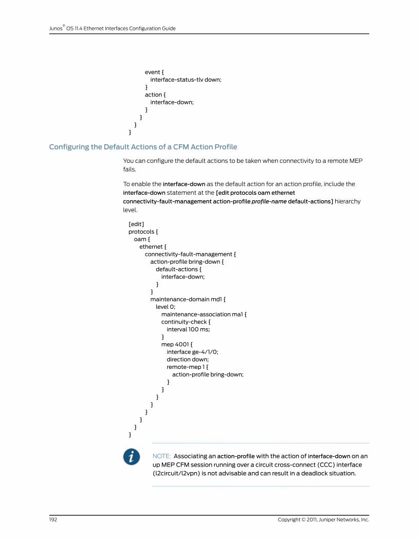
event {interface-status-tlv down;
}action {interface-down;
}}
}}
Configuring the Default Actions of a CFMAction Profile
You can configure the default actions to be taken when connectivity to a remote MEP
fails.
To enable the interface-down as the default action for an action profile, include the
interface-down statement at the [edit protocols oam ethernet
connectivity-fault-management action-profile profile-name default-actions] hierarchy
level.
[edit]protocols {oam {ethernet {connectivity-fault-management {action-profile bring-down {default-actions {interface-down;
}}maintenance-domainmd1 {level 0;maintenance-associationma1 {continuity-check {interval 100ms;
}mep 4001 {interface ge-4/1/0;direction down;remote-mep 1 {action-profile bring-down;
}}
}}
}}
}}
NOTE: Associating an action-profilewith the action of interface-down on an
upMEP CFM session running over a circuit cross-connect (CCC) interface(l2circuit/l2vpn) is not advisable and can result in a deadlock situation.
Copyright © 2011, Juniper Networks, Inc.192
Junos®
OS 11.4 Ethernet Interfaces Configuration Guide
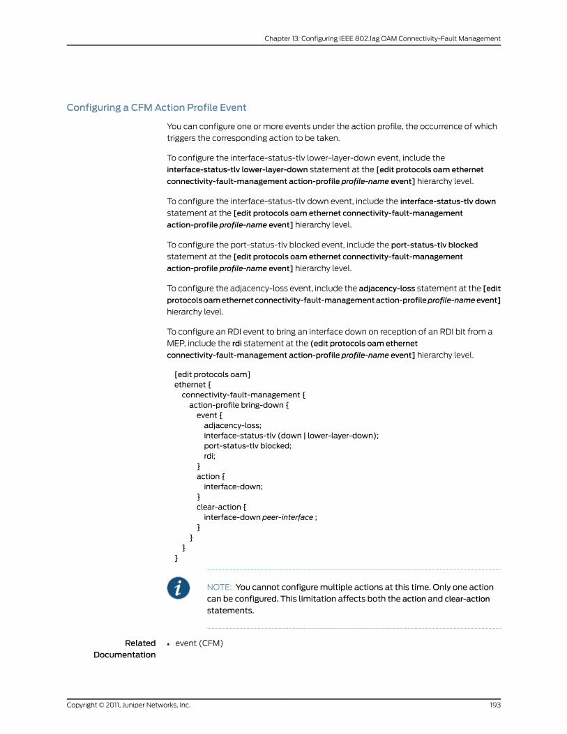
Configuring a CFMAction Profile Event
You can configure one or more events under the action profile, the occurrence of which
triggers the corresponding action to be taken.
To configure the interface-status-tlv lower-layer-down event, include the
interface-status-tlv lower-layer-down statement at the [edit protocols oam ethernet
connectivity-fault-management action-profile profile-name event] hierarchy level.
To configure the interface-status-tlv down event, include the interface-status-tlv down
statement at the [edit protocols oam ethernet connectivity-fault-management
action-profile profile-name event] hierarchy level.
To configure the port-status-tlv blocked event, include the port-status-tlv blocked
statement at the [edit protocols oam ethernet connectivity-fault-management
action-profile profile-name event] hierarchy level.
To configure the adjacency-loss event, include the adjacency-loss statement at the [edit
protocolsoamethernetconnectivity-fault-managementaction-profileprofile-nameevent]
hierarchy level.
To configure an RDI event to bring an interface down on reception of an RDI bit from a
MEP, include the rdi statement at the (edit protocols oam ethernet
connectivity-fault-management action-profile profile-name event] hierarchy level.
[edit protocols oam]ethernet {connectivity-fault-management {action-profile bring-down {event {adjacency-loss;interface-status-tlv (down | lower-layer-down);port-status-tlv blocked;rdi;
}action {interface-down;
}clear-action {interface-down peer-interface ;
}}
}}
NOTE: You cannot configuremultiple actions at this time. Only one actioncan be configured. This limitation affects both the action and clear-action
statements.
RelatedDocumentation
event (CFM)•
193Copyright © 2011, Juniper Networks, Inc.
Chapter 13: Configuring IEEE 802.1ag OAM Connectivity-Fault Management

• connectivity-fault-management
• IEEE 802.1ag OAM Connectivity Fault Management Overview on page 177
• Creating the Maintenance Domain on page 179
• Creating a Maintenance Association on page 183
• Configuring a Maintenance Endpoint on page 186
• Configuring 802.1ag Ethernet OAM for VPLS on page 223
• Junos OS Ethernet Interfaces Configuration Guide
Configuring Linktrace Protocol in CFM
The linktrace protocol is used for path discovery between a pair of maintenance points.
Linktrace messages are triggered by an administrator using the traceroute command to
verify the path between a pair of MEPs under the same maintenance association. Linktrace
messages can also be used to verify the path between an MEP and an MIP under the
same maintenance domain. The operation of IEEE 802.1ag linktrace request and response
messages is similar to the operation of Layer 3 traceroute commands. For more
information about the traceroute command, see the JunosOSSystemBasics Configuration
Guide.
Configuring the Linktrace Path Age Timer
If no response to a linktrace request is received, the request and response entries are
deleted after the age timer expires. To configure the linktrace age timer, use the linktrace
statement with the age time option at the [edit protocols oam ethernet
connectivity-fault-management] hierarchy level. The age is configured in minutes or
seconds.
Configuring the Linktrace Database Size
Configure the number of linktrace reply entries to be stored per linktrace request. To
configure the linktrace database size, use the linktrace statement with the
path-database-size path-database-size option at the [edit protocols oam ethernet
connectivity-fault-management] hierarchy level.
Display the linktrace database using the show oam ethernet
connectivity-fault-management path-database command.
RelatedDocumentation
connectivity-fault-management•
• IEEE 802.1ag OAM Connectivity Fault Management Overview on page 177
• Creating the Maintenance Domain on page 179
• Configuring Maintenance Intermediate Points on page 181
• Creating a Maintenance Association on page 183
• Continuity Check Protocol on page 184
• Configuring a Maintenance Endpoint on page 186
Copyright © 2011, Juniper Networks, Inc.194
Junos®
OS 11.4 Ethernet Interfaces Configuration Guide
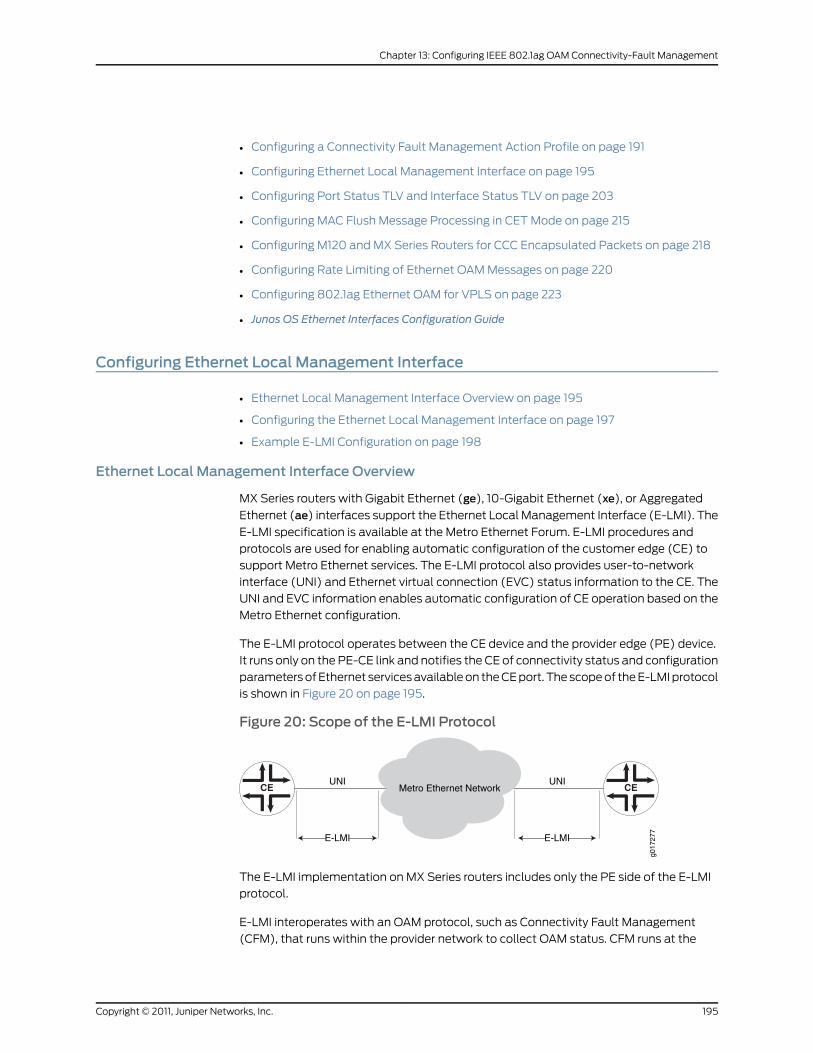
• Configuring a Connectivity Fault Management Action Profile on page 191
• Configuring Ethernet Local Management Interface on page 195
• Configuring Port Status TLV and Interface Status TLV on page 203
• Configuring MAC Flush Message Processing in CET Mode on page 215
• Configuring M120 and MX Series Routers for CCC Encapsulated Packets on page 218
• Configuring Rate Limiting of Ethernet OAM Messages on page 220
• Configuring 802.1ag Ethernet OAM for VPLS on page 223
• Junos OS Ethernet Interfaces Configuration Guide
Configuring Ethernet Local Management Interface
• Ethernet Local Management Interface Overview on page 195
• Configuring the Ethernet Local Management Interface on page 197
• Example E-LMI Configuration on page 198
Ethernet Local Management Interface Overview
MX Series routers with Gigabit Ethernet (ge), 10-Gigabit Ethernet (xe), or Aggregated
Ethernet (ae) interfaces support the Ethernet Local Management Interface (E-LMI). The
E-LMI specification is available at the Metro Ethernet Forum. E-LMI procedures and
protocols are used for enabling automatic configuration of the customer edge (CE) to
support Metro Ethernet services. The E-LMI protocol also provides user-to-network
interface (UNI) and Ethernet virtual connection (EVC) status information to the CE. The
UNI and EVC information enables automatic configuration of CE operation based on the
Metro Ethernet configuration.
The E-LMI protocol operates between the CE device and the provider edge (PE) device.
It runs only on the PE-CE link and notifies the CE of connectivity status and configuration
parameters of Ethernet services available on the CE port. The scope of the E-LMI protocol
is shown in Figure 20 on page 195.
Figure 20: Scope of the E-LMI Protocol
CE CE
g017
277
Metro Ethernet NetworkUNI UNI
E-LMI E-LMI
The E-LMI implementation on MX Series routers includes only the PE side of the E-LMI
protocol.
E-LMI interoperates with an OAM protocol, such as Connectivity Fault Management
(CFM), that runs within the provider network to collect OAM status. CFM runs at the
195Copyright © 2011, Juniper Networks, Inc.
Chapter 13: Configuring IEEE 802.1ag OAM Connectivity-Fault Management

provider maintenance level (UNI-N to UNI-N with up MEPs at the UNI). E-LMI relies on
the CFM for end-to-end status of EVCs across CFM domains (SVLAN domain or VPLS).
The E-LMI protocol relays the following information:
• Notification to the CE of the addition/deletion of an EVC (active, not active, or partially
active)
• Notification to the CE of the availability state of a configured EVC
• Communication of UNI and EVC attributes to the CE:
• UNI attributes:
• UNI identifier (a user-configured name for UNI)
• CE-VLAN ID/EVC map type (all-to-one bundling, service multiplexing with bundling,
or no bundling)
• Bandwidth profile is not supported (including the following features):
• CM (coupling mode)
• CF (color flag)
• CIR (committed Information rate)
• CBR (committed burst size)
• EIR (excess information rate)
• EBS (excess burst size)
• EVC attributes:
• EVC reference ID
• EVC status type (active, not active, or partially active)
• EVC type (point-to-point or multipoint-to-multipoint)
• EVC ID (a user-configured name for EVC)
• Bandwidth profile (not supported)
• CE-VLAN ID/EVC map
E-LMI on MX Series routers supports the following EVC types:
• Q-in-Q SVLAN (point-to-point or multipoint-to-multipoint)—Requires an end-to-end
CFM session between UNI-Ns to monitor the EVS status.
• VPLS (BGP or LDP) (point-to-point or multipoint-to-multipoint)—Either VPLS
pseudowire status or end-to-end CFM sessions between UNI-Ns can be used to monitor
EVC status.
• L2 circuit/L2VPN (point-to-point)—Either VPLS pseudowire status or end-to-end CFM
sessions between UNI-Ns can be used to monitor EVC status.
Copyright © 2011, Juniper Networks, Inc.196
Junos®
OS 11.4 Ethernet Interfaces Configuration Guide

NOTE: l2-circuit and l2vpn are not supported.
Configuring the Ethernet Local Management Interface
To configure E-LMI, perform the following steps:
• Configuring an OAM Protocol (CFM) on page 197
• Assigning the OAM Protocol to an EVC on page 197
• Enabling E-LMI on an Interface and Mapping CE VLAN IDs to an EVC on page 197
Configuring an OAMProtocol (CFM)
For information on configuring the OAM protocol (CFM), see “IEEE 802.1ag OAM
Connectivity Fault Management Overview” on page 177.
Assigning the OAMProtocol to an EVC
To configure an EVC, you must specify a name for the EVC using the evcsevc-id statement
at the [edit protocols oam ethernet] hierarchy level. You can set the EVC protocol for
monitoring EVC statistics to cfm or vpls using the evc-protocol statement and its options
at the [edit protocols oam ethernet evcs] hierarchy level.
You can set the number of remote UNIs in the EVC using the remote-uni-count number
statement at the [edit protocols oam ethernet evcs evcs-protocol] hierarchy level. The
remote-uni-count defaults to 1. Configuring a value greater than 1 makes the EVC
multipoint-to-multipoint. If you enter a value greater than the actual number of endpoints,
the EVC status will display as partially active even if all endpoints are up. If you enter a
remote-uni-count less than the actual number of endpoints, the status will display as
active, even if all endpoints are not up.
You can configure an EVC by including the evcs statement at the [edit protocols oamethernet] hierarchy level:
[edit protocols oam ethernet]evcs evc-id {evc-protocol (cfm(management-domainnamemanagement-associationname) | vpls(routing-instance name)) {remote-uni-count <number>; # Optional, defaults to 1multipoint-to-multipoint;# Optional, defaults to point-to-point if remote-uni-count is 1
}}
Enabling E-LMI on an Interface andMapping CE VLAN IDs to an EVC
To configure E-LMI, include the lmi statement at the [edit protocols oam ethernet]
hierarchy level:
[edit protocols oam ethernet]lmi {polling-verification-timer value;
197Copyright © 2011, Juniper Networks, Inc.
Chapter 13: Configuring IEEE 802.1ag OAM Connectivity-Fault Management

# Polling verification timer (T392), defaults to 15 secondsstatus-counter count; # Status counter (N393), defaults to 4interface name {evc evc-id {default-evc;vlan-list [ vlan-ids ];
}evc-map-type (all-to-one-bundling | bundling | service-multiplexing);polling-verification-time value; # Optional, defaults to global valuestatus-counter count; # Optional, defaults to global valueuni-id value; # Optional, defaults to interface-name
}}
You can set the status counter to count consecutive errors using the status-counter count
statement at the [edit protocols oam ethernet lmi] hierarchy level. The status counter is
used to determine if E-LMI is operational or not. The default value is 4.
You can set the polling-verification-timer value statement at the [edit protocols oam
ethernet lmi] hierarchy level. The default value is 15 seconds.
You can enable an interface and set its options for use with E-LMI using the interface
name statement at the [edit protocols oam ethernet lmi] hierarchy level. Only ge, xe, and
ae interfaces are supported. You can use the interface uni-id option to specify a name
for the UNI. If uni-id is not configured, it defaults to the name variable of interface name.
You can specify the CE-VLAN ID/EVC map type using the evc-map-type type interface
option. The options are all-to-one-bundling, bundling, or service-multiplexing. Service
multiplexing is with no bundling. The default type is all-to-one-bundling.
To specify the EVC that an interface uses, use the evc evc-id statement at the [edit
protocols oam ethernet lmi interface name] hierarchy level. You can specify an interface
as the default EVC interface using the default-evc statement at the [edit protocols oam
ethernet lmi interface name evc evc-id] hierarchy level. All VIDs that are not mapped to
any other EVCs are mapped to this EVC. Only one EVC can be configured as the default.
You can map a list of VLANs to an EVC using the vlan-list vlan-id-list statement at the
[edit protocols oam ethernet lmi interface name evc evc-id] hierarchy level.
Example E-LMI Configuration
Figure 21 on page 199 illustrates the E-LMI configuration for a point-to-point EVC (SVLAN)
monitored by CFM. In this example, VLANs 1 through 2048 are mapped to evc1 (SVLAN
100) and 2049 through 4096 are mapped to evc2 (SVLAN 200). Two CFM sessions are
created to monitor these EVCs.
Copyright © 2011, Juniper Networks, Inc.198
Junos®
OS 11.4 Ethernet Interfaces Configuration Guide

Figure 21: E-LMI Configuration for a Point-to-Point EVC (SVLAN)Monitored by CFM
g017
278
PE2PE1CE1 CE2ge-1/1/1
ge-1/1/2
ge-2/2/2
ge-2/2/1
CFM up MEP CFM up MEP
UNI-NUNI-C UNI-N UNI-CEthernet Virtual Connections
CFM sessions
E-LMI E-LMI
Configuring PE1
[edit]interfaces {ge-1/1/1 {unit 0 {family bridge {interface-mode trunk;vlan-id-list 1-2048;
}}unit 1 {family bridge {interface-mode trunk;vlan-id-list 2049-4096;
}}
}ge-1/1/2 {unit 0 {vlan-id 100;family bridge {interface-mode trunk;inner-vlan-id-list 1-2048;
}}unit 1 {vlan-id 200;family bridge {interface-mode trunk;inner-vlan-id-list 2049-4096;
}}
}}protocols {oam {ethernet {connectivity-fault-management {maintenance-domainmd {level 0;maintenance-association 1 {name-format vlan;mep 1 {
199Copyright © 2011, Juniper Networks, Inc.
Chapter 13: Configuring IEEE 802.1ag OAM Connectivity-Fault Management

direction up;interface ge-1/1/1.0 vlan 1;
}}maintenance-association 2049 {name-format vlan;mep 1 {direction up;interface ge-1/1/1.1 vlan 2049;
}}
}}evcs {evc1 {evc-protocol cfmmanagement-domainmdmanagement-association 1;remote-uni-count 1;
}evc2 {evc-protocol cfmmanagement-domainmdmanagement-association 2049;remote-uni-count 1;
}}lmi {interface ge-1/1/1 {evc evc1 {vlan-list 1-2048;
}evc evc2 {vlan-list 2049-4096;
}evc-map-type bundling;uni-id uni-ce1;
}}
}}
}
Configuring PE2
[edit]interfaces {ge-2/2/1 {unit 0 {family bridge {interface-mode trunk;vlan-id-list 1-2048;
}}unit 1 {family bridge {interface-mode trunk;vlan-id-list 2049-4096;
}}
Copyright © 2011, Juniper Networks, Inc.200
Junos®
OS 11.4 Ethernet Interfaces Configuration Guide

}ge-2/2/2 {unit 0 {vlan-id 100;family bridge {interface-mode trunk;inner-vlan-id-list 1-2048;
}}unit 1 {vlan-id 200;family bridge {interface-mode trunk;inner-vlan-id-list 2049-4095;
}}
}}protocols {oam {ethernet {connectivity-fault-management {maintenance-domainmd {level 0;maintenance-association 1 {name-format vlan;mep 1 {direction up;interface ge-2/2/1.0 vlan 1;
}}maintenance-association 2049 {name-format vlan;mep 1 {direction up;interface ge-2/2/1.1 vlan 2049;
}}
}}evcs {evc1 {evc-protocol cfmmanagement-domainmdmanagement-association 1;remote-uni-count 1;
}evc2 {evc-protocol cfmmanagement-domainmdmanagement-association 2049;uni-count 2;
}}lmi {interface ge-2/2/1 {evc evc1 {vlan-list 1-2048;
}evc evc2 {
201Copyright © 2011, Juniper Networks, Inc.
Chapter 13: Configuring IEEE 802.1ag OAM Connectivity-Fault Management
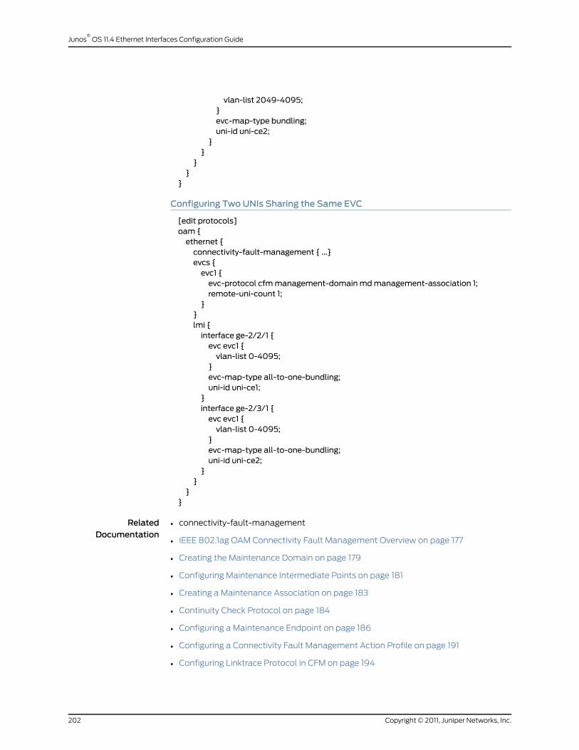
vlan-list 2049-4095;}evc-map-type bundling;uni-id uni-ce2;
}}
}}
}
Configuring TwoUNIs Sharing the Same EVC
[edit protocols]oam {ethernet {connectivity-fault-management { ...}evcs {evc1 {evc-protocol cfmmanagement-domainmdmanagement-association 1;remote-uni-count 1;
}}lmi {interface ge-2/2/1 {evc evc1 {vlan-list 0-4095;
}evc-map-type all-to-one-bundling;uni-id uni-ce1;
}interface ge-2/3/1 {evc evc1 {vlan-list 0-4095;
}evc-map-type all-to-one-bundling;uni-id uni-ce2;
}}
}}
RelatedDocumentation
connectivity-fault-management•
• IEEE 802.1ag OAM Connectivity Fault Management Overview on page 177
• Creating the Maintenance Domain on page 179
• Configuring Maintenance Intermediate Points on page 181
• Creating a Maintenance Association on page 183
• Continuity Check Protocol on page 184
• Configuring a Maintenance Endpoint on page 186
• Configuring a Connectivity Fault Management Action Profile on page 191
• Configuring Linktrace Protocol in CFM on page 194
Copyright © 2011, Juniper Networks, Inc.202
Junos®
OS 11.4 Ethernet Interfaces Configuration Guide

• Configuring Port Status TLV and Interface Status TLV on page 203
• Configuring MAC Flush Message Processing in CET Mode on page 215
• Configuring M120 and MX Series Routers for CCC Encapsulated Packets on page 218
• Configuring Rate Limiting of Ethernet OAM Messages on page 220
• Configuring 802.1ag Ethernet OAM for VPLS on page 223
• Junos OS Ethernet Interfaces Configuration Guide
Configuring Port Status TLV and Interface Status TLV
• TLVs Overview on page 203
• Various TLVs for CFM PDUs on page 203
• Support for Additional Optional TLVs on page 205
• MAC Status Defects on page 211
• Configuring Remote MEP Action Profile Support on page 212
TLVs Overview
Type, Length, and Value (TLVs) are described in the IEEE 802.1ag standard for CFM as
a method of encoding variable-length and/or optional information in a PDU. TLVs are
not aligned to any particular word or octet boundary. TLVs follow each other with no
padding between them.
Table 17 on page 203 shows the TLV format and indicates if it is required or optional.
Table 17: Format of TLVs
DescriptionOctet (sequence)Parameter
Required. If 0, no Length or Value fields follow. If not 0, at least the Lengthfield follows the Type field.
1Type
Required if the Type field is not 0. Not present if the Type field is 0. The 16 bitsof the Length field indicate the size, in octets, of the Value field. 0 in the Lengthfield indicates that there is no Value field.
2–3Length
Length specified by the Length field. Optional. Not present if the Type field is0 or if the Length field is 0.
4Value
Various TLVs for CFMPDUs
Table 18 on page 204 shows a set of TLVs defined by IEEE 802.1ag for various CFM PDU
types. Each TLV can be identified by the unique value assigned to its type field. Some
type field values are reserved.
203Copyright © 2011, Juniper Networks, Inc.
Chapter 13: Configuring IEEE 802.1ag OAM Connectivity-Fault Management

Table 18: Type Field Values for Various TLVs for CFMPDUs
Type FieldTLV or Organization
0End TLV
1Sender ID TLV
2Port Status TLV
3Data TLV
4Interface Status TLV
5Reply Ingress TLV
6Reply Egress TLV
7LTM Egress Identifier TLV
8LTR Egress Identifier TLV
9 to 30Reserved for IEEE 802.1
31Organization-Specific TLV
32 to 63Defined by ITU-T Y.1731
64 to 255Reserved for IEEE 802.1
Not every TLV is applicable for all types of CFM PDUs.
• TLVs applicable for continuity check message (CCM):
• End TLV
• Sender ID TLV
• Port Status TLV
• Interface Status TLV
• Organization-Specific TLV
• TLVs applicable for loopback message (LBM):
• End TLV
• Sender ID TLV
• Data TLV
• Organization-Specific TLV
Copyright © 2011, Juniper Networks, Inc.204
Junos®
OS 11.4 Ethernet Interfaces Configuration Guide

• TLVs applicable for loopback reply (LBR):
• End TLV
• Sender ID TLV
• Data TLV
• Organization-Specific TLV
• TLVs applicable for linktrace message (LTM):
• End TLV
• LTM Egress Identifier TLV
• Sender ID TLV
• Organization-Specific TLV
• TLVs applicable for linktrace reply (LTR):
• End TLV
• LTR Egress Identifier TLV
• Reply Ingress TLV
• Reply Egress TLV
• Sender ID TLV
• Organization-Specific TLV
The following TLVs are currently supported in the applicable CFM PDUs:
• End TLV
• Reply Ingress TLV
• Reply Egress TLV
• LTR Egress Identifier TLV
• LTM Egress Identifier TLV
• Data TLV
Support for Additional Optional TLVs
The following additional optional TLVs are supported:
• Port Status TLV
• Interface Status TLV
MX Series routers support configuration of port status TLV and interface status TLV.
Configuring the Port Status TLV allows the operator to control the transmission of the
Port Status TLV in CFM PDUs.
205Copyright © 2011, Juniper Networks, Inc.
Chapter 13: Configuring IEEE 802.1ag OAM Connectivity-Fault Management

NOTE: Although Port Status TLV configuration statements are visible in theCLI on M120 andM320 routers, Port Status TLV cannot be configured onthese systems. Port Status TLV can be enabled on aMEP interface only if itis a bridge logical interface, which is not possible on these systems.
For configuration information, see the following sections:
• Port Status TLV on page 206
• Interface Status TLV on page 208
Port Status TLV
The Port Status TLV indicates the ability of the bridge port on which the transmitting
MEP resides to pass ordinary data, regardless of the status of the MAC. The value of this
TLV is driven by the MEP variable enableRmepDefect, as shown in Table 20 on page 206.
The format of this TLV is shown in Table 19 on page 206.
Any change in the Port Status TLVs value triggers one extra transmission of that bridge
ports MEP CCMs.
Table 19: Port Status TLV Format
Octet (Sequence)Parameter
1Type = 2
2–3Length
4Value (See Table 20 on page 206)
Table 20: Port Status TLV Values
ValueOrdinary Data Passing Freely Through the PortMnemonic
1No: enableRmepDefect = falsepsBlocked
2Yes: enableRmepDefect = truepsUp
The MEP variable enableRmepDefect is a boolean variable indicating whether frames on
the service instance monitored by the maintenance associations if this MEP are enabled
to pass through this bridge port by the Spanning Tree Protocol and VLAN topology
management. It is set to TRUE if:
• The bridge port is set in a state where the traffic can pass through it.
• The bridge port is running multiple instances of the spanning tree.
• The MEP interface is not associated with a bridging domain.
Copyright © 2011, Juniper Networks, Inc.206
Junos®
OS 11.4 Ethernet Interfaces Configuration Guide

Configuring Port Status TLV
Junos OS provides configuration support for the Port Status TLV, allowing you to control
the transmission of this TLV in CCM PDUs. The Junos OS provides this configuration at
the continuity-check level. By default, the CCM does not include the Port Status TLV. To
configure the Port Status TLV, use the port-status-tlv statement at the [edit protocols
oam ethernet connectivity-fault-managementmaintenance-domain identifier
maintenance-association identifier continuity-check] hierarchy level.
NOTE: Port Status TLV configuration is not mandated by IEEE 802.1ag. TheJunos OS provides it in order to givemore flexibility to the operator; howeverit receives and processes CCMswith a Port Status TLV, regardless of thisconfiguration.
An example of the configuration statements follows:
protocols {oam {ethernet {connectivity-fault-management {maintenance-domain identifier {level number;maintenance-association identifier {continuity-check {interval number,loss-threshold number;hold-interval number;port-status-tlv; # Sets Port Status TLV
}}
}}
}}
}
You cannot enable Port Status TLV transmission in the following two cases:
• If the MEP interface under the maintenance-association is not of type bridge.
• If the MEP is configured on a physical interface.
Displaying the Received Port Status TLV
The Junos OS saves the last received Port Status TLV from a remote MEP. If the received
Port Status value does not correspond to one of the standard values listed in Table 20
on page 206, then the show command displays it as "unknown." You can display the last
saved received Port Status TLV using the show oam ethernet
connectivity-fault-managementmep-databasemaintenance-domain identifier
maintenance-association identifier local-mep identifier remote-mep identifier command,
as in the following example:
207Copyright © 2011, Juniper Networks, Inc.
Chapter 13: Configuring IEEE 802.1ag OAM Connectivity-Fault Management
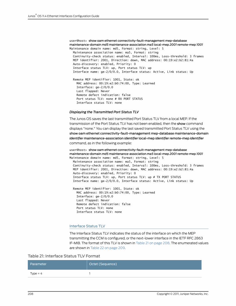
user@host> show oam ethernet connectivity-fault-managementmep-databasemaintenance-domainmd5maintenance-associationma5 local-mep 2001 remote-mep 1001Maintenance domain name: md5, Format: string, Level: 5 Maintenance association name: ma5, Format: string Continuity-check status: enabled, Interval: 100ms, Loss-threshold: 3 frames MEP identifier: 2001, Direction: down, MAC address: 00:19:e2:b2:81:4a Auto-discovery: enabled, Priority: 0 Interface status TLV: up, Port status TLV: up Interface name: ge-2/0/0.0, Interface status: Active, Link status: Up
Remote MEP identifier: 1001, State: ok MAC address: 00:19:e2:b0:74:00, Type: Learned Interface: ge-2/0/0.0 Last flapped: Never Remote defect indication: false Port status TLV: none # RX PORT STATUS Interface status TLV: none
Displaying the Transmitted Port Status TLV
The Junos OS saves the last transmitted Port Status TLV from a local MEP. If the
transmission of the Port Status TLV has not been enabled, then the show command
displays "none." You can display the last saved transmitted Port Status TLV using the
showoamethernet connectivity-fault-managementmep-databasemaintenance-domain
identifiermaintenance-association identifier local-mep identifier remote-mep identifier
command, as in the following example:
user@host> show oam ethernet connectivity-fault-managementmep-databasemaintenance-domainmd5maintenance-associationma5 local-mep 2001 remote-mep 1001Maintenance domain name: md5, Format: string, Level: 5 Maintenance association name: ma5, Format: string Continuity-check status: enabled, Interval: 100ms, Loss-threshold: 3 frames MEP identifier: 2001, Direction: down, MAC address: 00:19:e2:b2:81:4a Auto-discovery: enabled, Priority: 0 Interface status TLV: up, Port status TLV: up # TX PORT STATUS Interface name: ge-2/0/0.0, Interface status: Active, Link status: Up
Remote MEP identifier: 1001, State: ok MAC address: 00:19:e2:b0:74:00, Type: Learned Interface: ge-2/0/0.0 Last flapped: Never Remote defect indication: false Port status TLV: none Interface status TLV: none
Interface Status TLV
The Interface Status TLV indicates the status of the interface on which the MEP
transmitting the CCM is configured, or the next-lower interface in the IETF RFC 2863
IF-MIB. The format of this TLV is shown in Table 21 on page 208. The enumerated values
are shown in Table 22 on page 209.
Table 21: Interface Status TLV Format
Octet (Sequence)Parameter
1Type = 4
Copyright © 2011, Juniper Networks, Inc.208
Junos®
OS 11.4 Ethernet Interfaces Configuration Guide

Table 21: Interface Status TLV Format (continued)
Octet (Sequence)Parameter
2–3Length
4Value (See Table 22 on page 209)
Table 22: Interface Status TLV Values
ValueInterface StatusMnemonic
1upisUp
2downisDown
3testingisTesting
4unknownisUnknown
5dormantisDormant
6notPresentisNotPresent
7lowerLayerDownisLowerLayerDown
Configuring Interface Status TLV
The Junos OS provides configuration support for the Interface Status TLV, thereby allowing
operators to control the transmission of this TLV in CCM PDUs through configuration at
the continuity-check level.
NOTE: This configuration is not mandated by IEEE 802.1ag; rather it isprovided to givemore flexibility to the operator. The Junos OS receives andprocesses CCMswith the Interface Status TLV, regardless of thisconfiguration.
The interface status TLV configuration is shown below:
protocols {oam {ethernet {connectivity-fault-management {maintenance-domain identifier {level number;maintenance-association identifier {continuity-check {interval number;loss-threshold number;hold-interval number;interface-status-tlv; # Sets the interface status TLV
209Copyright © 2011, Juniper Networks, Inc.
Chapter 13: Configuring IEEE 802.1ag OAM Connectivity-Fault Management
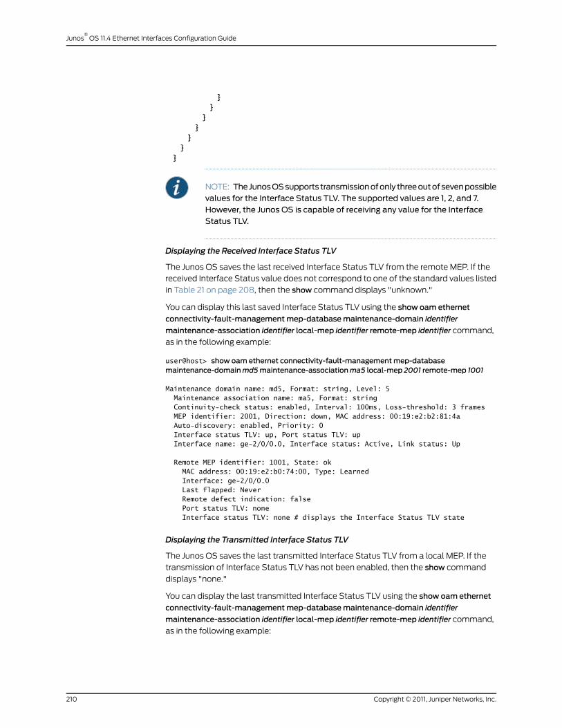
}}
}}
}}
}
NOTE: TheJunosOSsupports transmissionofonly threeoutofsevenpossiblevalues for the Interface Status TLV. The supported values are 1, 2, and 7.However, the Junos OS is capable of receiving any value for the InterfaceStatus TLV.
Displaying the Received Interface Status TLV
The Junos OS saves the last received Interface Status TLV from the remote MEP. If the
received Interface Status value does not correspond to one of the standard values listed
in Table 21 on page 208, then the show command displays "unknown."
You can display this last saved Interface Status TLV using the show oam ethernet
connectivity-fault-managementmep-databasemaintenance-domain identifier
maintenance-association identifier local-mep identifier remote-mep identifier command,
as in the following example:
user@host> show oam ethernet connectivity-fault-managementmep-databasemaintenance-domainmd5maintenance-associationma5 local-mep 2001 remote-mep 1001
Maintenance domain name: md5, Format: string, Level: 5 Maintenance association name: ma5, Format: string Continuity-check status: enabled, Interval: 100ms, Loss-threshold: 3 frames MEP identifier: 2001, Direction: down, MAC address: 00:19:e2:b2:81:4a Auto-discovery: enabled, Priority: 0 Interface status TLV: up, Port status TLV: up Interface name: ge-2/0/0.0, Interface status: Active, Link status: Up
Remote MEP identifier: 1001, State: ok MAC address: 00:19:e2:b0:74:00, Type: Learned Interface: ge-2/0/0.0 Last flapped: Never Remote defect indication: false Port status TLV: none Interface status TLV: none # displays the Interface Status TLV state
Displaying the Transmitted Interface Status TLV
The Junos OS saves the last transmitted Interface Status TLV from a local MEP. If the
transmission of Interface Status TLV has not been enabled, then the show command
displays "none."
You can display the last transmitted Interface Status TLV using the show oam ethernet
connectivity-fault-managementmep-databasemaintenance-domain identifier
maintenance-association identifier local-mep identifier remote-mep identifier command,
as in the following example:
Copyright © 2011, Juniper Networks, Inc.210
Junos®
OS 11.4 Ethernet Interfaces Configuration Guide
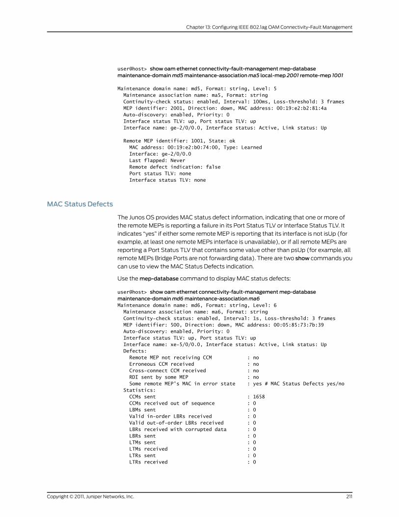
user@host> show oam ethernet connectivity-fault-managementmep-databasemaintenance-domainmd5maintenance-associationma5 local-mep 2001 remote-mep 1001
Maintenance domain name: md5, Format: string, Level: 5 Maintenance association name: ma5, Format: string Continuity-check status: enabled, Interval: 100ms, Loss-threshold: 3 frames MEP identifier: 2001, Direction: down, MAC address: 00:19:e2:b2:81:4a Auto-discovery: enabled, Priority: 0 Interface status TLV: up, Port status TLV: up Interface name: ge-2/0/0.0, Interface status: Active, Link status: Up
Remote MEP identifier: 1001, State: ok MAC address: 00:19:e2:b0:74:00, Type: Learned Interface: ge-2/0/0.0 Last flapped: Never Remote defect indication: false Port status TLV: none Interface status TLV: none
MACStatus Defects
The Junos OS provides MAC status defect information, indicating that one or more of
the remote MEPs is reporting a failure in its Port Status TLV or Interface Status TLV. It
indicates “yes” if either some remote MEP is reporting that its interface is not isUp (for
example, at least one remote MEPs interface is unavailable), or if all remote MEPs are
reporting a Port Status TLV that contains some value other than psUp (for example, all
remote MEPs Bridge Ports are not forwarding data). There are two show commands you
can use to view the MAC Status Defects indication.
Use the mep-database command to display MAC status defects:
user@host> show oam ethernet connectivity-fault-managementmep-databasemaintenance-domainmd6maintenance-associationma6Maintenance domain name: md6, Format: string, Level: 6 Maintenance association name: ma6, Format: string Continuity-check status: enabled, Interval: 1s, Loss-threshold: 3 frames MEP identifier: 500, Direction: down, MAC address: 00:05:85:73:7b:39 Auto-discovery: enabled, Priority: 0 Interface status TLV: up, Port status TLV: up Interface name: xe-5/0/0.0, Interface status: Active, Link status: Up Defects: Remote MEP not receiving CCM : no Erroneous CCM received : no Cross-connect CCM received : no RDI sent by some MEP : no Some remote MEP's MAC in error state : yes # MAC Status Defects yes/no Statistics: CCMs sent : 1658 CCMs received out of sequence : 0 LBMs sent : 0 Valid in-order LBRs received : 0 Valid out-of-order LBRs received : 0 LBRs received with corrupted data : 0 LBRs sent : 0 LTMs sent : 0 LTMs received : 0 LTRs sent : 0 LTRs received : 0
211Copyright © 2011, Juniper Networks, Inc.
Chapter 13: Configuring IEEE 802.1ag OAM Connectivity-Fault Management

Sequence number of next LTM request : 0 1DMs sent : 0 Valid 1DMs received : 0 Invalid 1DMs received : 0 DMMs sent : 0 DMRs sent : 0 Valid DMRs received : 0 Invalid DMRs received : 0 Remote MEP count: 1 Identifier MAC address State Interface 200 00:05:85:73:39:4a ok xe-5/0/0.0
Use the interfaces command to display MAC status defects:
user@host> show oam ethernet connectivity-fault-management interfaces detailInterface name: xe-5/0/0.0, Interface status: Active, Link status: Up Maintenance domain name: md6, Format: string, Level: 6 Maintenance association name: ma6, Format: string Continuity-check status: enabled, Interval: 1s, Loss-threshold: 3 frames Interface status TLV: up, Port status TLV: up MEP identifier: 500, Direction: down, MAC address: 00:05:85:73:7b:39 MEP status: running Defects: Remote MEP not receiving CCM : no Erroneous CCM received : no Cross-connect CCM received : no RDI sent by some MEP : no Some remote MEP's MAC in error state : yes # MAC Status Defects yes/no Statistics: CCMs sent : 1328 CCMs received out of sequence : 0 LBMs sent : 0 Valid in-order LBRs received : 0 Valid out-of-order LBRs received : 0 LBRs received with corrupted data : 0 LBRs sent : 0 LTMs sent : 0 LTMs received : 0 LTRs sent : 0 LTRs received : 0 Sequence number of next LTM request : 0 1DMs sent : 0 Valid 1DMs received : 0 Invalid 1DMs received : 0 DMMs sent : 0 DMRs sent : 0 Valid DMRs received : 0 Invalid DMRs received : 0 Remote MEP count: 1 Identifier MAC address State Interface 200 00:05:85:73:39:4a ok xe-5/0/0.0
Configuring RemoteMEP Action Profile Support
Based on values of interface-status-tlv and port-status-tlv in the received CCM packets,
a specific action, such as interface-down, can be taken using the action-profile options.
Multiple action profiles can be configured on the router, but only one action profile can
be assigned to a remote MEP.
Copyright © 2011, Juniper Networks, Inc.212
Junos®
OS 11.4 Ethernet Interfaces Configuration Guide
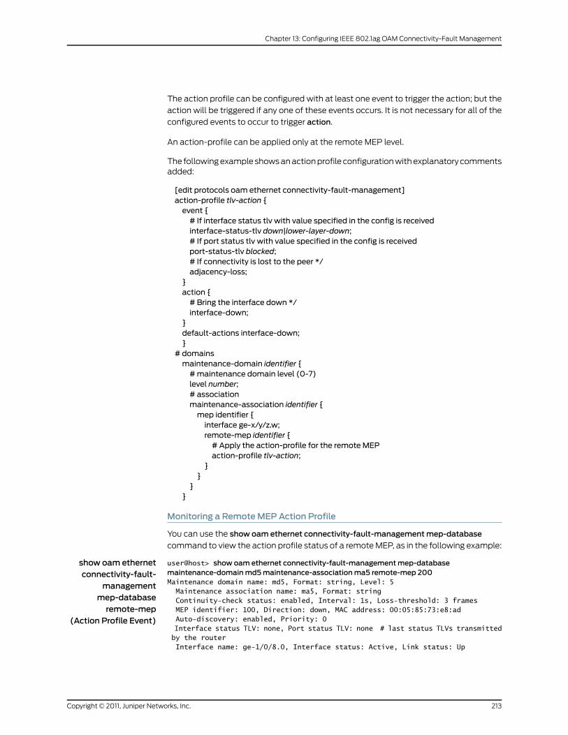
The action profile can be configured with at least one event to trigger the action; but the
action will be triggered if any one of these events occurs. It is not necessary for all of the
configured events to occur to trigger action.
An action-profile can be applied only at the remote MEP level.
The following example shows an action profile configuration with explanatory commentsadded:
[edit protocols oam ethernet connectivity-fault-management]action-profile tlv-action {event {# If interface status tlv with value specified in the config is receivedinterface-status-tlv down|lower-layer-down;# If port status tlv with value specified in the config is receivedport-status-tlv blocked;# If connectivity is lost to the peer */adjacency-loss;
}action {# Bring the interface down */interface-down;
}default-actions interface-down;}
# domainsmaintenance-domain identifier {#maintenance domain level (0-7)level number;# associationmaintenance-association identifier {mep identifier {interface ge-x/y/z.w;remote-mep identifier {# Apply the action-profile for the remote MEPaction-profile tlv-action;
}}
}}
Monitoring a RemoteMEP Action Profile
You can use the show oam ethernet connectivity-fault-managementmep-database
command to view the action profile status of a remote MEP, as in the following example:
show oam ethernetconnectivity-fault-
managementmep-databaseremote-mep
(Action Profile Event)
user@host> show oam ethernet connectivity-fault-managementmep-databasemaintenance-domainmd5maintenance-associationma5 remote-mep 200Maintenance domain name: md5, Format: string, Level: 5 Maintenance association name: ma5, Format: string Continuity-check status: enabled, Interval: 1s, Loss-threshold: 3 frames MEP identifier: 100, Direction: down, MAC address: 00:05:85:73:e8:ad Auto-discovery: enabled, Priority: 0 Interface status TLV: none, Port status TLV: none # last status TLVs transmitted by the router Interface name: ge-1/0/8.0, Interface status: Active, Link status: Up
213Copyright © 2011, Juniper Networks, Inc.
Chapter 13: Configuring IEEE 802.1ag OAM Connectivity-Fault Management

Remote MEP identifier: 200, State: ok # displays the remote MEP name and state
MAC address: 00:05:85:73:96:1f, Type: Configured Interface: ge-1/0/8.0 Last flapped: Never Remote defect indication: false Port status TLV: none Interface status TLV: lower-layer-down Action profile: juniper # displays remote MEP’s action profile identifier Last event: Interface-status-tlv lower-layer-down # last remote MEP event
# to trigger action Action: Interface-down, Time: 2009-03-27 14:25:10 PDT (00:00:02 ago) # action occurrence time
RelatedDocumentation
connectivity-fault-management•
• IEEE 802.1ag OAM Connectivity Fault Management Overview on page 177
• Creating the Maintenance Domain on page 179
• Configuring Maintenance Intermediate Points on page 181
• Creating a Maintenance Association on page 183
• Continuity Check Protocol on page 184
• Configuring a Maintenance Endpoint on page 186
• Configuring a Connectivity Fault Management Action Profile on page 191
• Configuring Linktrace Protocol in CFM on page 194
• Configuring Ethernet Local Management Interface on page 195
• Configuring MAC Flush Message Processing in CET Mode on page 215
• Configuring M120 and MX Series Routers for CCC Encapsulated Packets on page 218
• Configuring Rate Limiting of Ethernet OAM Messages on page 220
• Configuring 802.1ag Ethernet OAM for VPLS on page 223
• Junos OS Ethernet Interfaces Configuration Guide
Copyright © 2011, Juniper Networks, Inc.214
Junos®
OS 11.4 Ethernet Interfaces Configuration Guide
ConfiguringMAC FlushMessage Processing in CETMode
In carrier Ethernet transport (CET) mode, MX Series routers are used as provider edge
(PE) routers, and Nokia Siemens Networks A2200 Carrier Ethernet Switches (referred
to as E-domain devices) that run standard-based protocols are used in the access side.
On the MX Series routers, VPLS pseudowires are configured dynamically through label
distribution protocol (LDP). On the E-domain devices, topology changes are detected
through connectivity fault management (CFM) sessions running between the E-domain
devices and the MX Series PE routers. The MX Series PE routers can bring the carrier
Ethernet interface down if there is CFM connectivity loss. This triggers a local MAC flush
as well as a targeted label distribution protocol (T-LDP) MAC flush notification that gets
sent towards the remote MX Series PEs to trigger MAC flush on them.
In CET inter-op mode, MX Series routers need to interoperate with the Nokia Siemens
Networks Ax100 Carrier Ethernet access devices (referred to as A-domain devices) that
run legacy protocols. Nokia Siemens Networks A4100 and A8100 devices act as an
intermediate between the MX Series PE routers and A-domain devices. These intermediate
devices perform interworking function (IWF) procedures so that operations administration
management (OAM) sessions can be run between MX Series routers and A-domain
devices. There are no VPLS pseudowires between the MX Series PE routers and the Nokia
Siemens Networks A4100 and A8100 intermediate devices, so there is no LDP protocol
running between the PE routers to send topology change notifications. In order to
communicate topology changes, MX Series routers can trigger a MAC flush and propagate
it in the core. MX Series routers can use action profiles based upon the connection
protection type length value (TLV) event. The action profile brings down the carrier edge
logical interface in MX Series PE routers, which will trigger a local MAC flush and also
propagate the topology change to the core using LDP notification.
For VPLS there is no end-to-end connectivity monitored. The access rings are
independently monitored by running CFM down multiple end points (MEPs) on the
working and protection paths for each of the services between the E-domain devices
and the MX Series PE routers, and between the A-domain devices and the MX Series PE
routers the IWF hosted by the Nokia Siemens Networks A-4100 devices. When there is
a connectivity failure on the working path, the Nokia Siemens Networks Ax200 devices
perform a switchover to the protection path, triggering a topology change notification
(in the form of TLVs carried in CCM) to be sent on the active path.
215Copyright © 2011, Juniper Networks, Inc.
Chapter 13: Configuring IEEE 802.1ag OAM Connectivity-Fault Management
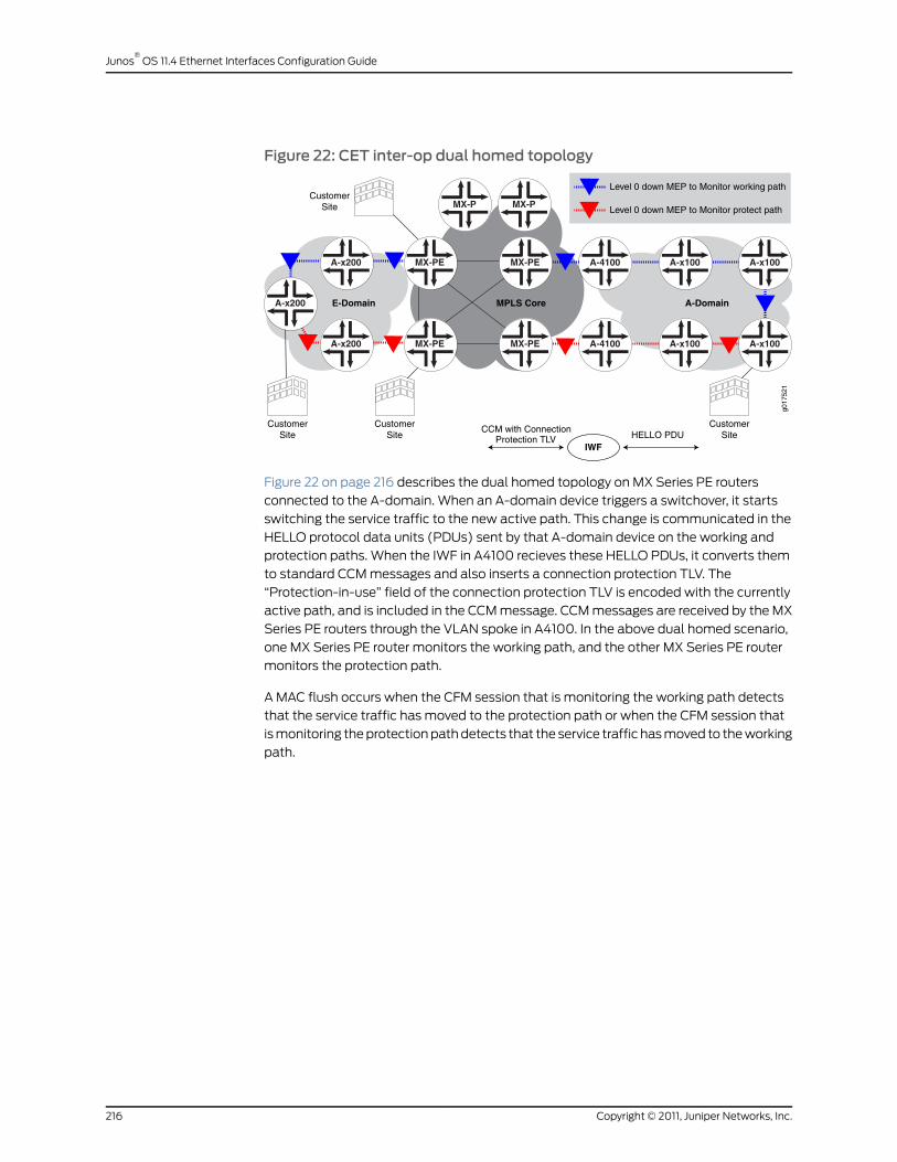
Figure 22: CET inter-op dual homed topology
MX-PE A-4100MX-PE A-x100A-x200 A-x100
MX-PE
MX-P
A-4100MX-PE A-x100A-x200 A-x100
MX-P
E-Domain MPLS Core A-Domain
CCM with ConnectionProtection TLV HELLO PDU
IWF
g017
521
A-x200
Level 0 down MEP to Monitor working path
Level 0 down MEP to Monitor protect path
CustomerSite
CustomerSite
CustomerSite
CustomerSite
Figure 22 on page 216 describes the dual homed topology on MX Series PE routers
connected to the A-domain. When an A-domain device triggers a switchover, it starts
switching the service traffic to the new active path. This change is communicated in the
HELLO protocol data units (PDUs) sent by that A-domain device on the working and
protection paths. When the IWF in A4100 recieves these HELLO PDUs, it converts them
to standard CCM messages and also inserts a connection protection TLV. The
“Protection-in-use” field of the connection protection TLV is encoded with the currently
active path, and is included in the CCM message. CCM messages are received by the MX
Series PE routers through the VLAN spoke in A4100. In the above dual homed scenario,
one MX Series PE router monitors the working path, and the other MX Series PE router
monitors the protection path.
A MAC flush occurs when the CFM session that is monitoring the working path detects
that the service traffic has moved to the protection path or when the CFM session that
is monitoring the protection path detects that the service traffic has moved to the working
path.
Copyright © 2011, Juniper Networks, Inc.216
Junos®
OS 11.4 Ethernet Interfaces Configuration Guide
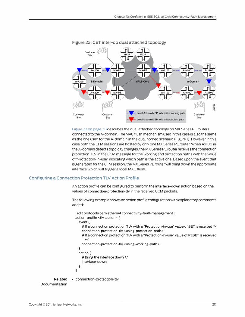
Figure 23: CET inter-op dual attached topology
MX-PE A-x100A-x200 A-x100
A-x200
MX-P
A-4100MX-PE A-x100A-x200 A-x100
MX-P
E-Domain MPLS Core A-Domain
Level 0 down MEP to Monitor working path
Level 0 down MEP to Monitor protect path
g017
522
A-4100
MX-PE
CustomerSite
CustomerSite
CustomerSite
CustomerSite
Figure 23 on page 217describes the dual attached topology on MX Series PE routers
connected to the A-domain. The MAC flush mechanism used in this case is also the same
as the one used for the A-domain in the dual homed scenario (Figure 1). However in this
case both the CFM sessions are hosted by only one MX Series PE router. When Ax100 in
the A-domain detects topology changes, the MX Series PE router receives the connection
protection TLV in the CCM message for the working and protection paths with the value
of “Protection-in-use” indicating which path is the active one. Based upon the event that
is generated for the CFM session, the MX Series PE router will bring down the appropriate
interface which will trigger a local MAC flush.
Configuring a Connection Protection TLV Action Profile
An action profile can be configured to perform the interface-down action based on the
values of connection-protection-tlv in the received CCM packets.
The following example shows an action profile configuration with explanatory comments
added:
[edit protocols oam ethernet connectivity-fault-management]action-profile <tlv-action> {event {# If a connection protection TLVwith a “Protection-in-use” value of SET is received */connection-protection-tlv <using-protection-path>;# If a connection protection TLVwith a “Protection-in-use” value of RESET is received*/
connection-protection-tlv <using-working-path>;}action {# Bring the interface down */interface-down;
}}
RelatedDocumentation
connection-protection-tlv•
217Copyright © 2011, Juniper Networks, Inc.
Chapter 13: Configuring IEEE 802.1ag OAM Connectivity-Fault Management

• IEEE 802.1ag OAM Connectivity Fault Management Overview on page 177
• Creating the Maintenance Domain on page 179
• Configuring Maintenance Intermediate Points on page 181
• Creating a Maintenance Association on page 183
• Continuity Check Protocol on page 184
• Configuring a Maintenance Endpoint on page 186
• Configuring a Connectivity Fault Management Action Profile on page 191
• Configuring Linktrace Protocol in CFM on page 194
• Configuring Ethernet Local Management Interface on page 195
• Configuring Port Status TLV and Interface Status TLV on page 203
• Configuring M120 and MX Series Routers for CCC Encapsulated Packets on page 218
• Configuring Rate Limiting of Ethernet OAM Messages on page 220
• Configuring 802.1ag Ethernet OAM for VPLS on page 223
• Junos OS Ethernet Interfaces Configuration Guide
ConfiguringM120 andMX Series Routers for CCC Encapsulated Packets
• IEEE 802.1ag CFM OAM Support for CCC Encapsulated Packets Overview on page 218
• CFM Features Supported on Layer 2 VPN Circuits on page 218
• Configuring CFM for CCC Encapsulated Packets on page 219
IEEE 802.1ag CFMOAMSupport for CCC Encapsulated Packets Overview
Layer 2 virtual private network (L2VPN) is a type of virtual private network service used
to transport customer's private Layer 2 traffic (for example, Ethernet, ATM or Frame
Relay) over the service provider's shared IP/MPLS infrastructure. The service provider
edge (PE) router must have an interface with circuit cross-connect (CCC) encapsulation
to switch the customer edge (CE) traffic to the public network.
The IEEE 802.1ag Ethernet Connectivity Fault Management (CFM) is an OAM standard
used to perform fault detection, isolation, and verification on virtual bridge LANs. M120
and MX Series routers provide CFM support for bridge/VPLS/routed interfaces and
support 802.1ag Ethernet OAM for CCC encapsulated packets.
CFM Features Supported on Layer 2 VPN Circuits
CFM features supported on L2VPN circuits are as follows:
• Creation of up/down MEPs at any level on the CE-facing logical interfaces.
• Creation of MIPs at any level on the CE-facing logical interfaces.
• Support for continuity check, loopback, and linkrace protocol.
Copyright © 2011, Juniper Networks, Inc.218
Junos®
OS 11.4 Ethernet Interfaces Configuration Guide

• Support for the Y1731 Ethernet Delay measurement protocol.
• Support for action profiles to bring the CE-facing logical interfaces down when loss of
connectivity is detected.
Figure 24: Layer 2 VPN Topology
g017
327
Level 7Level 6
Level 0
ge-1/1/1
ge-2/2/0
pseudowire
ge-0/0/0
ge-1/0/1
ge-0/0/0 ge-2/0/0PE2PE1
Level 0
Up MEPDown MEP
Up MEPDown MEP
CE1 CE2Down MEPDown MEP
To monitor the L2VPN circuit, a CFM up MEP (Level 6 in Figure 24 on page 219) can be
configured on the CE-facing logical interfaces of provider edge routers PE1 and PE2. To
monitor the CE-PE attachment circuit, a CFM down MEP can be configured on the
customer logical interfaces of CE1-PE1 and CE2-PE2 (Level 0 in Figure 24 on page 219).
Configuring CFM for CCC Encapsulated Packets
The only change from the existing CLI configuration is the introduction of a new commandto create a MIP on the CE-facing interface of the PE router.
protocols {oam {ethernet {connectivity-fault-management {# Define amaintenance domains for each default level.#; These names are specified as DEFAULT_level_numbermaintenance-domain DEFAULT_x {# L2VPN CE interfaceinterface (ge | xe)-fpc/pic/port.domain;
}{level number;maintenance-association identifier {mepmep-id {direction (up | down);# L2 VPN CE interface on which encapsulation family CCC is configured.interface (ge | xe)-fpc/pic/port.domain;auto-discovery;priority number;
}}
}}
}}
}
RelatedDocumentation
connectivity-fault-management•
• IEEE 802.1ag OAM Connectivity Fault Management Overview on page 177
• Creating the Maintenance Domain on page 179
219Copyright © 2011, Juniper Networks, Inc.
Chapter 13: Configuring IEEE 802.1ag OAM Connectivity-Fault Management
• Configuring Maintenance Intermediate Points on page 181
• Creating a Maintenance Association on page 183
• Continuity Check Protocol on page 184
• Configuring a Maintenance Endpoint on page 186
• Configuring a Connectivity Fault Management Action Profile on page 191
• Configuring Linktrace Protocol in CFM on page 194
• Configuring Ethernet Local Management Interface on page 195
• Configuring Port Status TLV and Interface Status TLV on page 203
• Configuring MAC Flush Message Processing in CET Mode on page 215
• Configuring Rate Limiting of Ethernet OAM Messages on page 220
• Configuring 802.1ag Ethernet OAM for VPLS on page 223
• Junos OS Ethernet Interfaces Configuration Guide
Configuring Rate Limiting of Ethernet OAMMessages
M Series, M320 with Enhanced III FPC, M120, M7i and M10 with CFEB, and MX Series
routers support rate limiting of Ethernet OAM messages. Depending on the connectivity
fault management (CFM) configuration, CFM packets are discarded, sent to the CPU for
processing, or flooded to other bridge interfaces. This feature allows the router to intercept
incoming CFM packets for prevention of DoS attacks.
You can apply rate limiting of Ethernet OAM messages at either of two CFM policing
levels, as follows:
• Global-level CFM policing—uses a policer at the global level to police the CFM traffic
belonging to all the sessions.
• Session-level CFM policing—uses a policer created to police the CFM traffic belonging
to one session.
To configure global-level CFM policing, include the policer statement and its options at
the [edit protocols oam ethernet connectivity-fault-management] hierarchy level.
To configure session-level CFM policing, include the policer statement at the [edit
protocols oam ethernet connectivity-fault-managementmaintenance-domain name level
numbermaintenance-association name] hierarchy level.
The following example shows a CFM policer used for rate-limiting CFM:
[edit]firewall {policer cfm-policer {if-exceeding {bandwidth-limit 8k;burst-size-limit 2k;
}
Copyright © 2011, Juniper Networks, Inc.220
Junos®
OS 11.4 Ethernet Interfaces Configuration Guide
then discard;}
}
Case 1: Global-LevelCFMPolicing
This example shows a global level policer, at the CFM level, for rate-limiting CFM. Thecontinuity-check cfm-policer statement at the global connectivity-fault-managementpolicer hierarchy level specifies the policer to use for policing all continuity check packetsof the CFM traffic belonging to all sessions. The other cfm-policer1 statement at theconnectivity-fault-management policer hierarchy level specifies the policer to use forpolicing all non-continuity check packets of the CFM traffic belonging to all sessions. Theall cfm-policer2 statement specifies to police all CFM packets with the specified policercfm-policer2. If the all policer-name option is used, then the user cannot specify theprevious continuity-check and other options.
[edit protocols oam ethernet]connectivity-fault-management {policer {continuity-check cfm-policer;other cfm-policer1 ;# all cfm-policer2;}
}
Case 2: Session-LevelCFMPolicing
This example shows a session-level CFM policer used for rate-limiting CFM. The policerstatement at the session connectivity-fault-managementmaintenance-domainmdmaintenance-associationma hierarchy level specifies the policer to use for policing onlycontinuity check packets of the CFM traffic belonging to the specified session. The othercfm-policer1 statement at the connectivity-fault-managementmaintenance-domainmdmaintenance-associationma hierarchy level specifies the policer to use for policing allnon-continuity check packets of the CFM traffic belonging to this session only. The allcfm-policer2 statement specifies to police all CFM packets with the specified policercfm-policer2. If the all policer-name option is used, then the user cannot specify theprevious continuity-check and other options.
[edit protocols oam ethernet]connectivity-fault-management {maintenance-domainmd {level number;maintenance-associationma {continuity-check {interval 1s;
}policer {continuity-check cfm-policer;other cfm-policer1;# all cfm-policer2;}mep 1 {interface ge-3/3/0.0;direction up;auto-discovery;
}}
}}
221Copyright © 2011, Juniper Networks, Inc.
Chapter 13: Configuring IEEE 802.1ag OAM Connectivity-Fault Management

In the case of global CFM policing, the same policer is shared across multiple CFM sessions.
In per-session CFM policing, a separate policer must be created to rate-limit packets
specific to that session.
NOTE:
Service-level policer configuration for any two CFM sessions on the sameinterface at different levels must satisfy the following constraints if thedirection of the sessions is the same:
• If one session is configured with policer all, then the other session cannot
have a policer all or policer other configuration.
• If onesession is configuredwithpolicerother, then theother sessioncannot
have a policer all or policer other configuration.
A commit error will occur if such a configuration is committed.
NOTE: Policers with PBB andMIPs are not supported.
RelatedDocumentation
connectivity-fault-management•
• IEEE 802.1ag OAM Connectivity Fault Management Overview on page 177
• Creating the Maintenance Domain on page 179
• Configuring Maintenance Intermediate Points on page 181
• Creating a Maintenance Association on page 183
• Continuity Check Protocol on page 184
• Configuring a Maintenance Endpoint on page 186
• Configuring a Connectivity Fault Management Action Profile on page 191
• Configuring Linktrace Protocol in CFM on page 194
• Configuring Ethernet Local Management Interface on page 195
• Configuring Port Status TLV and Interface Status TLV on page 203
• Configuring MAC Flush Message Processing in CET Mode on page 215
• Configuring M120 and MX Series Routers for CCC Encapsulated Packets on page 218
• Configuring 802.1ag Ethernet OAM for VPLS on page 223
• Junos OS Ethernet Interfaces Configuration Guide
Copyright © 2011, Juniper Networks, Inc.222
Junos®
OS 11.4 Ethernet Interfaces Configuration Guide
Configuring 802.1ag Ethernet OAM for VPLS
BEST PRACTICE: The logical interfaces in a VPLS routing instancemay havethe same or different VLAN configurations. VLAN normalization is requiredto switch packets correctly among these interfaces. VLAN normalization iseffectively VLAN translation wherein the VLAN tags of the received packetneed to be translated if they are different than the normalized VLAN tags.Configuration is described starting in “IEEE 802.1ag OAMConnectivity FaultManagement Overview” on page 177 and you should further observe theadditional requirements described in this section.
For MX Series routers, the normalized VLAN is specified using one of thefollowing configuration statements in the VPLS routing instance:
• vlan-id vlan-number
• vlan-id none
• vlan-tags outer outer-vlan-number inner inner-vlan-number
Youmust configure vlan-maps explicitly on all interfaces belonging to the
routing instance.
The following forwarding path considerationsmust be observed:
• Packet receive path:
• This is the forwarding path for packets received on the interfaces.
• 802.1ag Ethernet OAM for VPLS uses implicit interface filters andforwarding table filters to flood, accept, and drop the CFM packets.
• Packet transmit path:
• The JUNOS Software uses the router’s hardware-based forwarding forCPU-generated packets.
• For DownMEPs, the packets are transmitted on the interface on whichthe MEP is configured.
• ForUpMEPs, thepacketmust be flooded toother interfaces in theVPLSrouting instance. The router creates a flood route tied to a flood next hop(withall interfaces to flood)and thensources thepacket tobe forwardedwith this flood route.
• The router also uses implicit-based forwarding for CPU generatedpackets. The result is for the flood next hop tied to the flood route to betied to the filter term. The filter term usesmatch criteria to correctlyidentify the host- generated packets.
223Copyright © 2011, Juniper Networks, Inc.
Chapter 13: Configuring IEEE 802.1ag OAM Connectivity-Fault Management

RelatedDocumentation
connectivity-fault-management•
• Example: Configuring Ethernet CFM over VPLS
• IEEE 802.1ag OAM Connectivity Fault Management Overview on page 177
• IEEE 802.1ag OAM Connectivity Fault Management Overview on page 177
• Creating the Maintenance Domain on page 179
• Configuring Maintenance Intermediate Points on page 181
• Creating a Maintenance Association on page 183
• Continuity Check Protocol on page 184
• Configuring a Maintenance Endpoint on page 186
• Configuring a Connectivity Fault Management Action Profile on page 191
• Configuring Linktrace Protocol in CFM on page 194
• Configuring Ethernet Local Management Interface on page 195
• Configuring Port Status TLV and Interface Status TLV on page 203
• Configuring MAC Flush Message Processing in CET Mode on page 215
• Configuring M120 and MX Series Routers for CCC Encapsulated Packets on page 218
• Configuring Rate Limiting of Ethernet OAM Messages on page 220
• Junos OS Ethernet Interfaces Configuration Guide
Configuring Unified ISSU for 802.1ag CFM
A unified in-service software upgrade (ISSU) enables you to upgrade between two
different Junos OS releases with no disruption on the control plane and with minimal
disruption of traffic. Unified ISSU is automatically enabled for the Connectivity Fault
Management (CFM) protocols and interoperates between local and remote maintenance
endpoints (MEPs).
The Junos OS provides support for unified ISSU using the loss threshold type length value
(TLV), which is automatically enabled for CFM. TLVs are described in the IEEE 802.1ag
standard for CFM as a method of encoding variable-length and optional information in
a protocol data unit (PDU). The loss threshold TLV indicates the loss threshold value of
a remote MEP. The loss threshold TLV is transmitted as part of the CFM continuity check
messages.
During a unified ISSU, the control plane may go down for several seconds and cause CFM
continuity check packets to get dropped. This may cause the remote MEP to detect a
connectivity loss and mark the MEP as down. To keep the MEP active during a unified
ISSU, the loss threshold TLV communicates the minimum threshold value the receiving
MEP requires to keep the MEP active. The receiving MEP parses the TLV and updates the
loss threshold value, but only if the new threshold value is greater than the locally
configured threshold value.
Copyright © 2011, Juniper Networks, Inc.224
Junos®
OS 11.4 Ethernet Interfaces Configuration Guide

An overview of CFM is described starting in “IEEE 802.1ag OAM Connectivity Fault
Management Overview” on page 177, and you should further observe the additional
requirements described in this topic.
Table 23 on page 225 shows the Loss Threshold TLV format.
Table 23: Loss Threshold TLV Format
DescriptionOctet (sequence)Parameter
Required.1Type=31
Required.2Length=12
Organization unique identifier (OUI), which is controlled by the IEEE andis typically the first three bytes of a MAC address (Juniper OUI 0x009069).
3OUI
Organizationally defined subtype.1Subtype
Loss threshold value.4Value
Bit0 (identifies an ISSU is in progress)
Bit1-31 (reserved)
4Flag
Junos OS provides configuration support for theconvey-loss-thresholdstatement, allowing
you to control the transmission of the loss threshold TLV in continuity check messages
PDUs. The convey-loss-threshold statement specifies that the loss threshold TLV must
be transmitted as part of the continuity check messages. If the convey-loss-threshold
statement is not specified, continuity check messages transmit this TLV only when a
unified ISSU is in progress. The Junos OS provides this configuration at the
continuity-check level. By default, continuity check messages do not include the loss
threshold TLV.
To configure the convey loss threshold, use the convey-loss-threshold statement at the
[editprotocolsoamethernetconnectivity-fault-managementmaintenance-domain identifier
maintenance-association identifier continuity-check] hierarchy level.
For the remote MEP, the loss threshold TLV is transmitted only during the unified ISSU
if the convey-loss-threshold statement is not configured. The remote MEP switches back
to the default loss threshold if no loss threshold TLV is received or the TLV has a default
threshold value of 3.
An example of the configuration statements follows:
protocols {oam {ethernet {connectivity-fault-management {maintenance-domain identifier {level number;maintenance-association identifier {continuity-check {
225Copyright © 2011, Juniper Networks, Inc.
Chapter 13: Configuring IEEE 802.1ag OAM Connectivity-Fault Management
convey-loss-threshold;interval number;loss-threshold number;hold-interval number;
}}
}}
}}
}
The Junos OS saves the last received loss threshold TLV from the remote MEP. You can
display the last saved loss threshold TLV that is received by the remote MEP, using the
showoamethernet connectivity-fault-managementmep-databasemaintenance-domain
identifiermaintenance-association identifier local-mep identifier remote-mep identifier
command, as in the following example:
user@host> show oam ethernet connectivity-fault-managementmep-databasemaintenance-domainmd3maintenance-associationma5 local-mep 2 remote-mep 1Maintenance domain name: md3, Format: string, Level: 3 Maintenance association name: ma3, Format: string Continuity-check status: enabled, Interval: 1s, Loss-threshold: 3 frames MEP identifier: 2, Direction: up, MAC address: 00:19:e2:b0:76:be Auto-discovery: enabled, Priority: 0 Interface status TLV: none, Port status TLV: none Connection Protection TLV: yes Prefer me: no, Protection in use: no, FRR Flag: no Interface name: xe-4/1/1.0, Interface status: Active, Link status: Up Loss Threshold TLV: Loss Threshold: 3 , Flag: 0x0
Remote MEP identifier: 1, State: ok MAC address: 00:1f:12:b7:ce:79, Type: Learned Interface: xe-4/1/1.0 Last flapped: Never Continuity: 100%, Admin-enable duration: 45sec, Oper-down duration: 0sec Effective loss threshold: 3 frames Remote defect indication: false Port status TLV: none Interface status TLV: none Connection Protection TLV: Prefer me: no, Protection in use: no, FRR Flag: no Loss Threshold TLV: #Displays last received value Loss Threshold: 3 , Flag: 0x0
The Junos OS saves the last transmitted loss threshold TLV from a local MEP. You can
display the last transmitted loss threshold TLV and the effective loss (operational)
threshold for the remote MEP, using theshowoamethernetconnectivity-fault-management
mep-databasemaintenance-domain identifiermaintenance-association identifier local-mep
identifier remote-mep identifier command, as in the following example:
user@host> show oam ethernet connectivity-fault-managementmep-databasemaintenance-domainmd3maintenance-associationma5 local-mep 2 remote-mep 1Maintenance domain name: md3, Format: string, Level: 3 Maintenance association name: ma3, Format: string Continuity-check status: enabled, Interval: 1s, Loss-threshold: 3 frames MEP identifier: 2, Direction: up, MAC address: 00:19:e2:b0:76:be Auto-discovery: enabled, Priority: 0
Copyright © 2011, Juniper Networks, Inc.226
Junos®
OS 11.4 Ethernet Interfaces Configuration Guide

Interface status TLV: none, Port status TLV: none Connection Protection TLV: yes Prefer me: no, Protection in use: no, FRR Flag: no Interface name: xe-4/1/1.0, Interface status: Active, Link status: Up Loss Threshold TLV: #Displays last transmitted value Loss Threshold: 3 , Flag: 0x0
Remote MEP identifier: 1, State: ok MAC address: 00:1f:12:b7:ce:79, Type: Learned Interface: xe-4/1/1.0 Last flapped: Never Continuity: 100%, Admin-enable duration: 45sec, Oper-down duration: 0sec Effective loss threshold: 3 frames #Displays operational threshold Remote defect indication: falsePort status TLV: none Interface status TLV: none Connection Protection TLV: Prefer me: no, Protection in use: no, FRR Flag: no Loss Threshold TLV: Loss Threshold: 3 , Flag: 0x0
RelatedDocumentation
Example: Configuring Ethernet CFM over VPLS•
• IEEE 802.1ag OAM Connectivity Fault Management Overview on page 177
Configuring CCM for Better Scalability
This topic describes how to configure CCM for better scalability. Junos OS provides
enhancements to trigger faster protection-switching and convergence in the event of
failures in Ethernet domains for Carrier Ethernet services. These enhancements can be
used when CE devices in the Ethernet domain detect faster service failures and propagates
the information in the interface-status TLV of the continuity-check messages (CCMs).
When CCMs are received, PE devices can perform certain actions which facilitates faster
protection-switching and convergence.
• Configuring Faster Protection Switching on page 227
• Configuring Faster Convergence on page 229
• Configuring a Primary VLAN ID on page 230
• Configuring a Remote Maintenance Association on page 230
Configuring Faster Protection Switching
You can apply an action profile to provide faster protection switching for point-to-point
network topologies with local switching configured. In a normal state, CCM sessions are
configured on the working and protect interfaces. The CCM packets transmitted contain
an interface-status TLV with the value up on the working interface and value down on
the protect interface. When a link fails on the working interface, the protect interface
starts receiving the interface-status TLV as up. With the profile configuration, if the
interface-status TLV received on the protect interface is up, the working interface is
automatically marked as interface-down.
227Copyright © 2011, Juniper Networks, Inc.
Chapter 13: Configuring IEEE 802.1ag OAM Connectivity-Fault Management

To configure the interface-status-tlv down event, include the interface-status-tlv down
statement at the [edit protocols oam ethernet connectivity-fault-management
action-profile profile-name event] hierarchy level.
To configure interface-down as the action profile’s action, include the interface-down
statement at the [edit protocols oam ethernet connectivity-fault-management
action-profile profile-name action] hierarchy level.
To configure interface-down peer-interface as the clear-action, include interface-down
peer-interface at the [edit protocols oam ethernet connectivity-fault-management
action-profile profile-name clear-action] hierarchy level.
[edit protocols oam]ethernet {connectivity-fault-management {action-profile p1 {event {interface-status-tlv down;
}action {interface-down;
}clear-action {interface-down peer-interface;
}}
}}
In this action profile configuration, when the interface-status TLV is received as up, the
peer-interface is marked as down.
The peer-interface is configured in the protect-maintenance-association statement.
Consider the following example using the protect-maintenance-association statement
in the configuration:
[edit protocols oam]ethernet {connectivity-fault-management {action-profile p1 {event {adjacency-loss;
}action {interface-down;
}clear-action {interface-down peer-interface;
}}maintenance-domain nsn {level 5;maintenance-associationma1 {protect-maintenance-associationma2;continuity-check {
Copyright © 2011, Juniper Networks, Inc.228
Junos®
OS 11.4 Ethernet Interfaces Configuration Guide
interval 100ms;connection-protection-tlv;
}mep 100 {interface ge-1/1/0.0;direction down;auto-discovery;
}}maintenance-associationma2 {continuity-check {interval 100ms;connection-protection-tlv;
}mep 101 {
interface ge-1/2/0.0;direction down;auto-discovery;
}remote-mep 100action-profile p1;
}}
}}
Configuring Faster Convergence
You can apply an action profile to provide faster convergence for dual-homed
multipoint-to-multipoint network topologies. If a multipoint-to-multipoint Ethernet
service uses MAC-based forwarding and stale MAC addresses exist in the learning tables,
this can result in traffic black holes in the network where incoming traffic is silently
discarded, without informing the source that the data did not reach its intended recipient.
With the profile configuration, if the interface-status TLV received on the protect interface
is up, then the interface-status TLV on the working interface is marked as down and the
PE device for the protect interface propagates a remote MAC-flush message to the PE
devices in the virtual private LAN service (VPLS) by using TLDP-MAC-FLUSH. The MAC
flush avoids traffic blackholing due to stale mac-db entries.
To configure the interface-status-tlv down event, include the interface-status-tlv down
statement at the [edit protocols oam ethernet connectivity-fault-management
action-profile profile-name event] hierarchy level.
To configure propagate-remote-flush as the action profile’s action, include the
propagate-remote-flush statement at the [edit protocols oam ethernet
connectivity-fault-management action-profile profile-name action] hierarchy level.
To configure propagate-remote-flush as the clear-action, include the
propagate-remote-flush statement at the [edit protocols oam ethernet
connectivity-fault-management action-profile profile-name clear-action] hierarchy level.
[edit protocols oam]ethernet {connectivity-fault-management {
229Copyright © 2011, Juniper Networks, Inc.
Chapter 13: Configuring IEEE 802.1ag OAM Connectivity-Fault Management

action-profile test {event {interface-status-tlv down;
}action {propagate-remote-mac-flush;
}clear-action {propagate-remote-mac-flush;
}}
}}
In this action profile configuration, when the incoming CCM packet contains the
interface-status TLV with value down, thepropagate-remote-mac-flushaction is triggered
for the action-profile.
Configuring a Primary VLAN ID
You can assign a primary virtual LAN (VLAN) ID in the maintenance association for
increased flexibility in the number of tags. When a vlan-range or vlan-id-list is configured
on an interface, the service OAM must run on one of the VLANs. The VLAN assigned for
service monitoring is considered the primary VLAN. If a primary-vid is not configured,
Junos OS assigns the first VLAN from the vlan-range or vlan-id-list. In earlier releases,
Junos OS assigned VLAN 4095.
To configure a primary VLAN ID, you can specify the primary-vid statement at the [edit
protocolsoamethernetconnectivity-fault-managementmaintenance-domaindomain-name
maintenance-associationma-name] hierarchy level:
[edit protocols oam ethernet connectivity-fault-management]maintenance domainmd3 {level 3;maintenance-associationma3 {primary-vid 2000;continuity-check {interval 10ms;connection-protection-tlv;
}mep 2 {interface ge-2/2/0.0;direction up;auto-discovery;
}}
}
Configuring a RemoteMaintenance Association
You can configure a maintenance association to accept a different maintenance
association identifier (ID) from a neighbor by including a remote-maintenance-association
statement. The 802.1ag CCM sessions expect the same maintenance association identifier
from its neighbors. If there is a maintenance association identifier mismatch, the PDUs
are marked as error PDUs. If a remote-maintenance-association statement is configured,
Copyright © 2011, Juniper Networks, Inc.230
Junos®
OS 11.4 Ethernet Interfaces Configuration Guide

a different maintenance association identifier is accepted and the 802.1ag CCM sessions
do not mark the CCM PDUs as error PDUs when the maintenance-association name is
the same as the name specified in the remote-maintenance-association statement.
To configure a remote maintenance association, include the
remote-maintenance-association statement at the [edit protocols oam ethernet
connectivity-fault-managementmaintenance-domain domain-name
maintenance-associationma-name] hierarchy level:
[edit protocols oam ethernet connectivity-fault-management]maintenance domainmd3 {level 1;maintenance-associationma3 {remote-maintenance-association fix-ma;continuity-check {interval 10ms;connection-protection-tlv;
}mep 2 {interface ge-2/2/0.0;direction up;auto-discovery;
}}
}
Using this configuration, interoperability is improved for CCMs with low-end CE devices
supporting fixed maintenance association identifier configurations.
231Copyright © 2011, Juniper Networks, Inc.
Chapter 13: Configuring IEEE 802.1ag OAM Connectivity-Fault Management

Copyright © 2011, Juniper Networks, Inc.232
Junos®
OS 11.4 Ethernet Interfaces Configuration Guide

CHAPTER 14
Configuring ITU-T Y.1731 Ethernet ServiceOAM
• Service-Level Agreement Measurement on page 234
• Ethernet Frame Delay Measurements Overview on page 234
• Ethernet Frame Loss Measurement Overview on page 240
• On-Demand Mode on page 241
• Proactive Mode on page 242
• Ethernet Failure Notification Protocol Overview on page 243
• Configuring an Iterator Profile on page 244
• Configuring a Remote MEP with an Iterator Profile on page 246
• Configuring Statistical Frame Loss Measurement for VPLS Connections on page 247
• Guidelines for Configuring Routers to Support an ETH-DM Session on page 248
• Guidelines for Starting an ETH-DM Session on page 249
• Guidelines for Managing ETH-DM Statistics and ETH-DM Frame Counts on page 252
• Configuring Routers to Support an ETH-DM Session on page 256
• Starting an ETH-DM Session on page 259
• Managing ETH-DM Statistics and ETH-DM Frame Counts on page 261
• Managing ETH-LM Statistics on page 264
• Managing Iterator Statistics on page 266
• Managing Continuity Measurement Statistics on page 270
• Example: One-Way Ethernet Frame Delay Measurement on page 271
• Example: Configuring an Iterator on page 278
• Configuring the Failure Notification Protocol on page 280
233Copyright © 2011, Juniper Networks, Inc.

Service-Level Agreement Measurement
Service-level agreement (SLA) measurement is the process of monitoring the bandwidth,
delay, delay variation (jitter), continuity, and availability of a service (E-Line or E-LAN).
It enables you to identify network problems before customers are impacted by network
defects.
NOTE:
The Ethernet VPN services can be classified into:
• Peer-to-peer-services (E-Line services)—The E-Line services are offeredusing MPLS-based Layer 2 VPN virtual private wire service (VPWS).
• Multipoint-to-multipoint services (E-LAN services)—The E-LAN servicesare offered using MPLS-based virtual private LAN service (VPLS).
For more information, see the Junos VPNs Configuration Guide.
In Junos OS, SLA measurements are classified into:
• On-demand mode—In on-demand mode, the measurements are triggered through
the CLI. For more information, see “On-Demand Mode” on page 241.
• Proactive mode—In proactive mode, the measurements are triggered by an iterator
application. For more information, see “Proactive Mode” on page 242.
For more information about frame delay measurement, see “Ethernet Frame Delay
Measurements Overview” on page 234. For more information about frame loss
measurement, see “Ethernet Frame Loss Measurement Overview” on page 240. Note that
Ethernet frame delay measurement and Ethernet frame loss measurement are not
supported on the ae interface.
RelatedDocumentation
Proactive Mode on page 242.•
• On-Demand Mode on page 241.
• Junos OS Ethernet Interfaces Configuration Guide
Ethernet Frame DelayMeasurements Overview
• ITU-T Y.1731 Frame Delay Measurement Feature on page 235
• One-Way Ethernet Frame Delay Measurement on page 236
• Two-Way Ethernet Frame Delay Measurement on page 237
• Choosing Between One-Way and Two-Way ETH-DM on page 239
• Restrictions for Ethernet Frame Delay Measurement on page 239
Copyright © 2011, Juniper Networks, Inc.234
Junos®
OS 11.4 Ethernet Interfaces Configuration Guide
ITU-T Y.1731 Frame DelayMeasurement Feature
The IEEE 802.3-2005 standard for Ethernet Operations, Administration, and Maintenance
(OAM) defines a set of link fault management mechanisms to detect and report link
faults on a single point-to-point Ethernet LAN.
Junos OS supports key OAM standards that provide for automated end-to-end
management and monitoring of Ethernet service by service providers:
• IEEE Standard 802.1ag, also known as “Connectivity Fault Management (CFM).”
• ITU-TRecommendationY.1731, which uses different terminology than IEEE 802.1ag and
defines Ethernet service OAM features for fault monitoring, diagnostics, and
performance monitoring.
These capabilities allow operators to offer binding service-level agreements (SLAs) and
generate new revenues from rate- and performance-guaranteed service packages that
are tailored to the specific needs of their customers.
Ethernet CFM
The IEEE 802.1ag standard for connectivity fault management (CFM) defines mechanisms
to provide for end-to-end Ethernet service assurance over any path, whether a single link
or multiple links spanning networks composed of multiple LANs.
For Ethernet interfaces on M320, MX Series, and T Series routers, Junos OS supports the
following key elements of the Ethernet CFM standard:
• Fault monitoring using the IEEE 802.1ag Ethernet OAM Continuity Check protocol
• Path discovery and fault verification using the IEEE 802.1ag Ethernet OAM Linktrace
protocol
• Fault isolation using the IEEE 802.1ag Ethernet OAM Loopback protocol
In a CFM environment, network entities such as network operators, service providers, and
customers may be part of different administrative domains. Each administrative domain
is mapped into one maintenance domain. Maintenance domains are configured with
different level values to keep them separate. Each domain provides enough information
for the entities to perform their own management and end-to-end monitoring, and still
avoid security breaches.
Figure 25 on page 236 shows the relationships among the customer, provider, and operator
Ethernet bridges, maintenance domains, maintenance association end points (MEPs),
and maintenance intermediate points (MIPs).
235Copyright © 2011, Juniper Networks, Inc.
Chapter 14: Configuring ITU-T Y.1731 Ethernet Service OAM
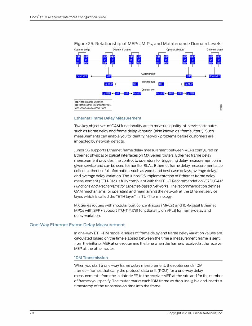
Figure 25: Relationship of MEPs, MIPs, andMaintenance Domain Levels
Ethernet Frame DelayMeasurement
Two key objectives of OAM functionality are to measure quality-of-service attributes
such as frame delay and frame delay variation (also known as “frame jitter”). Such
measurements can enable you to identify network problems before customers are
impacted by network defects.
Junos OS supports Ethernet frame delay measurement between MEPs configured on
Ethernet physical or logical interfaces on MX Series routers. Ethernet frame delay
measurement provides fine control to operators for triggering delay measurement on a
given service and can be used to monitor SLAs. Ethernet frame delay measurement also
collects other useful information, such as worst and best case delays, average delay,
and average delay variation. The Junos OS implementation of Ethernet frame delay
measurement (ETH-DM) is fully compliant with the ITU-T Recommendation Y.1731,OAM
Functions and Mechanisms for Ethernet-based Networks. The recommendation defines
OAM mechanisms for operating and maintaining the network at the Ethernet service
layer, which is called the "ETH layer" in ITU-T terminology.
MX Series routers with modular port concentrators (MPCs) and 10-Gigabit Ethernet
MPCs with SFP+ support ITU-T Y.1731 functionality on VPLS for frame-delay and
delay-variation.
One-Way Ethernet Frame DelayMeasurement
In one-way ETH-DM mode, a series of frame delay and frame delay variation values are
calculated based on the time elapsed between the time a measurement frame is sent
from the initiator MEP at one router and the time when the frame is received at the receiver
MEP at the other router.
1DM Transmission
When you start a one-way frame delay measurement, the router sends 1DM
frames—frames that carry the protocol data unit (PDU) for a one-way delay
measurement—from the initiator MEP to the receiver MEP at the rate and for the number
of frames you specify. The router marks each 1DM frame as drop-ineligible and inserts a
timestamp of the transmission time into the frame.
Copyright © 2011, Juniper Networks, Inc.236
Junos®
OS 11.4 Ethernet Interfaces Configuration Guide
1DMReception
When an MEP receives a 1DM frame, the router that contains the receiver MEP measures
the one-way delay for that frame (the difference between the time the frame was received
and the timestamp contained in the frame itself) and the delay variation (the difference
between the current and previous delay values).
One-Way ETH-DMStatistics
The router that contains the receiver MEP stores each set of one-way delay statistics in
the ETH-DM database. The ETH-DM database collects up to 100 sets of statistics for
any given CFM session (pair of peer MEPs). You can access these statistics at any time
by displaying the ETH-DM database contents.
One-Way ETH-DM Frame Counts
Each router counts the number of one-way ETH-DM frames sent and received:
• For an initiator MEP, the router counts the number of 1DM frames sent.
• For a receiver MEP, the router counts the number of valid 1DM frames received and the
number of invalid 1DM frames received.
Each router stores ETH-DM frame counts in the CFM database. The CFM database stores
CFM session statistics and, for interfaces that support ETH-DM, any ETH-DM frame
counts. You can access the frame counts at any time by displaying CFM database
information for Ethernet interfaces assigned to MEPs or for MEPs in CFM sessions.
Synchronization of SystemClocks
The accuracy of one-way delay calculations depends on close synchronization of the
system clocks at the initiator MEP and receiver MEP.
The accuracy of one-way delay variation is not dependent on system clock
synchronization. Because delay variation is simply the difference between consecutive
one-way delay values, the out-of-phase period is eliminated from the frame jitter values.
NOTE: For agivenone-wayEthernet framedelaymeasurement, framedelayand framedelayvariationvaluesareavailableonlyon the router that containsthe receiver MEP.
Two-Way Ethernet Frame DelayMeasurement
In two-way ETH-DM mode, frame delay and frame delay variation values are based on
the time difference between when the initiator MEP transmits a request frame and
receives a reply frame from the responder MEP, subtracting the time elapsed at the
responder MEP.
DMMTransmission
When you start a two-way frame delay measurement, the router sends delay
measurement message (DMM) frames— frames that carry the PDU for a two-way
237Copyright © 2011, Juniper Networks, Inc.
Chapter 14: Configuring ITU-T Y.1731 Ethernet Service OAM

ETH-DM request—from the initiator MEP to the responder MEP at the rate and for the
number of frames you specify. The router marks each DMM frame as drop-ineligible and
inserts a timestamp of the transmission time into the frame.
DMR Transmission
When an MEP receives a DMM frame, the responder MEP responds with a delay
measurement reply (DMR) frame, which carries ETH-DM reply information and a copy
of the timestamp contained in the DMM frame.
DMRReception
When an MEP receives a valid DMR, the router that contains the MEP measures the
two-way delay for that frame based on the following sequence of timestamps:
1. TITxDMM
2. TRRxDMM
3. TRTxDMR
4. TIRxDMR
A two-way frame delay is calculated as follows:
[TIRxDMR
– TITxDMM
] – [TRTxDMR
– TRRxDMM
]
The calculation show that frame delay is the difference between the time at which the
initiator MEP sends a DMM frame and the time at which the initiator MEP receives the
associated DMR frame from the responder MEP, minus the time elapsed at the responder
MEP.
The delay variation is the difference between the current and previous delay values.
Two-Way ETH-DMStatistics
The router that contains the initiator MEP stores each set of two-way delay statistics in
the ETH-DM database. The ETH-DM database collects up to 100 sets of statistics for
any given CFM session (pair of peer MEPs). You can access these statistics at any time
by displaying the ETH-DM database contents.
Two-Way ETH-DM Frame Counts
Each router counts the number of two-way ETH-DM frames sent and received:
• For an initiator MEP, the router counts the number DMM frames transmitted, the number
of valid DMR frames received, and the number of invalid DMR frames received.
• For a responder MEP, the router counts the number of DMR frames sent.
Each router stores ETH-DM frame counts in the CFM database. The CFM database stores
CFM session statistics and, for interfaces that support ETH-DM, any ETH-DM frame
counts. You can access the frame counts at any time by displaying CFM database
information for Ethernet interfaces assigned to MEPs or for MEPs in CFM sessions.
Copyright © 2011, Juniper Networks, Inc.238
Junos®
OS 11.4 Ethernet Interfaces Configuration Guide
NOTE: Foragiven two-wayEthernet framedelaymeasurement, framedelayand framedelayvariationvaluesareavailableonlyat the router that containsthe initiator MEP.
Choosing Between One-Way and Two-Way ETH-DM
One-way frame delay measurement requires that the system clocks at the initiator MEP
and receiver MEP are closely synchronized. Two-way frame delay measurement does
not require synchronization of the two systems. If it is not practical for the clocks to be
synchronized, two-way frame delay measurements are more accurate.
When two systems are physically close to each other, their one-way delay values are
very high compared to their two-way delay values. One-way delay measurement requires
that the timing for the two systems be synchronized at a very granular level, and MX
Series routers currently do not support this granular synchronization.
Restrictions for Ethernet Frame DelayMeasurement
The following restrictions apply to the Ethernet frame delay measurement feature:
• The ETH-DM feature is not supported on aggregated Ethernet interfaces or
label-switched interface. (LSI) pseudowires.
• Hardware-assisted timestamping for ETH-DM frames in the reception path is only
supported for MEP interfaces on Enhanced DPCs and Enhanced Queuing DPCs in MX
Series routers. For information about hardware-assisted timestamping, see “Guidelines
for Configuring Routers to Support an ETH-DM Session” on page 248 and “Enabling the
Hardware-Assisted Timestamping Option” on page 258.
• Ethernet frame delay measurements can be triggered only when the distributed periodic
packet management daemon (ppm) is enabled. For more information about this
limitation, see “Guidelines for Configuring Routers to Support an ETH-DM Session” on
page 248 and “Ensuring That Distributed ppm Is Not Disabled” on page 257.
• You can monitor only one session at a time to the same remote MEP or MAC address.
For more information about starting an ETH-DM session, see “Starting an ETH-DM
Session” on page 259.
• ETH-DM statistics are collected at only one of the two peer routers in the ETH-DM
session. For a one-way ETH-DM session, you can display frame ETH-DM statistics at
the receiver MEP only, using ETH-DM-specific showcommands. For a two-way ETH-DM
session, you can display frame delay statistics at the initiator MEP only, using the same
ETH-DM-specific show commands. For more information, see “Managing ETH-DM
Statistics and ETH-DM Frame Counts” on page 261.
• ETH-DM frame counts are collected at both MEPs and are stored in the respective
CFM databases.
• If graceful Routing Engine switchover (GRES) occurs, any collected ETH-DM statistics
are lost, and ETH-DM frame counts are reset to zeroes. Therefore, the collection of
ETH-DM statistics and ETH-DM frame counters has to be restarted, after the switchover
is complete. GRES enables a router with dual Routing Engines to switch from a master
239Copyright © 2011, Juniper Networks, Inc.
Chapter 14: Configuring ITU-T Y.1731 Ethernet Service OAM
Routing Engine to a backup Routing Engine without interruption to packet forwarding.
For more information, see the Junos OS High Availability Configuration Guide.
• Accuracy of frame delay statistics is compromised when the system is changing (such
as from reconfiguration). We recommend performing Ethernet frame delay
measurements on a stable system.
RelatedDocumentation
Ethernet Frame Loss Measurement Overview on page 240•
• Example: One-Way Ethernet Frame Delay Measurement on page 271
• Guidelines for Configuring Routers to Support an ETH-DM Session on page 248
• Guidelines for Starting an ETH-DM Session on page 249
• Guidelines for Managing ETH-DM Statistics and ETH-DM Frame Counts on page 252
• On-Demand Mode on page 241
• Proactive Mode on page 242
• Junos OS Ethernet Interfaces Configuration Guide
Ethernet Frame LossMeasurement Overview
The key objectives of the OAM functionality are to measure quality-of-service attributes
such as frame delay, frame delay variation (also known as “frame jitter”), and frame loss.
Such measurements enable you to identify network problems before customers are
impacted by network defects. For more information about Ethernet frame delay
measurement, see “Ethernet Frame Delay Measurements Overview” on page 234.
Junos OS supports Ethernet frame loss measurement (ETH-LM) between maintenance
association end points (MEPs) configured on Ethernet physical or logical interfaces on
MX Series routers and is presently supported only for VPWS service. ETH-LM is used by
operators to collect counter values applicable for ingress and egress service frames.
These counters maintain a count of transmitted and received data frames between a
pair of MEPs. Ethernet frame loss measurement is performed by sending frames with
ETH-LM information to a peer MEP and similarly receiving frames with ETH-LM information
from the peer MEP. This type of frame loss measurement is also known as single-ended
Ethernet loss measurement.
ETH-LM supports the following frame loss measurements:
• Near-end frame loss measurement—Measurement of frame loss associated with
ingress data frames.
• Far-end frame loss measurement—Measurement of frame loss associated with egress
data frames.
The Junos OS implementation of Ethernet frame delay measurement (ETH-DM) is fully
compliant with the ITU-T Recommendation Y.1731, as described in OAM Functions and
MechanismsforEthernet-BasedNetworks. The recommendation defines OAM mechanisms
for operating and maintaining the network at the Ethernet service layer, which is called
the "ETH layer" in ITU-T terminology.
Copyright © 2011, Juniper Networks, Inc.240
Junos®
OS 11.4 Ethernet Interfaces Configuration Guide

RelatedDocumentation
Managing Continuity Measurement Statistics on page 270•
• On-Demand Mode on page 241
• Proactive Mode on page 242
• Junos OS Ethernet Interfaces Configuration Guide
On-DemandMode
In on-demand mode, the measurements are triggered by the user through the CLI.
When the user triggers the delay measurement through the CLI, the delay measurement
request that is generated is as per the frame formats specified by the ITU-T Y.1731
standard. For two-way delay measurement, the server-side processing can be delegated
to the Packet Forwarding Engine to prevent overloading on the Routing Engine. For more
information, see “Configuring Routers to Support an ETH-DM Session” on page 256. When
the server-side processing is delegated to the Packet Forwarding Engine, the delay
measurement message (DMM) frame receive counters and delay measurement reply
(DMR) frame transmit counters are not displayed by the show command.
When the user triggers the loss measurement through the CLI, the router sends the
packets in standard format along with the loss measurement TLV. By default, the
session-id-tlv argument is included in the packet to allow concurrent loss measurement
sessions from same local MEP. You can also disable the session ID TLV by using the
no-session-id-tlv argument.
Single-ended ETH-LM is used for on-demand operation, administration, and maintenance
purposes. An MEP sends frames with ETH-LM request information to its peer MEP and
receives frames with ETH-LM reply information from its peer MEP to carry out loss
measurements. The protocol data unit (PDU) used for a single-ended ETH-LM request
is referred to as a loss measurement message (LMM) and the PDU used for a single-ended
ETH-LM reply is referred to as a loss measurement reply (LMR).
RelatedDocumentation
Ethernet Frame Delay Measurements Overview on page 234•
• Ethernet Frame Loss Measurement Overview on page 240
• Proactive Mode on page 242
• Configuring Routers to Support an ETH-DM Session on page 256.
• Junos OS Ethernet Interfaces Configuration Guide
241Copyright © 2011, Juniper Networks, Inc.
Chapter 14: Configuring ITU-T Y.1731 Ethernet Service OAM

Proactive Mode
In proactive mode, SLA measurements are triggered by an iterator application. An iterator
is designed to periodically transmit SLA measurement packets in form of
ITU-Y.1731-compliant frames for two-way delay measurement or loss measurement on
MX Series routers. This mode differs from on-demand SLA measurement, which is user
initiated. The iterator sends periodic delay or loss measurement request packets for each
of the connections registered to it. Iterators make sure that measurement cycles do not
occur at the same time for the same connection to avoid CPU overload. Junos OS supports
proactive mode for VPWS. For an iterator to form a remote adjacency and to become
functionally operational, the continuity check message (CCM) must be active between
the local and remote MEP configurations of the connectivity fault management (CFM).
Any change in the iterator adjacency parameters resets the existing iterator statistics
and restarts the iterator. Here, the term adjacency refers to a pairing of two endpoints
(either connected directly or virtually) with relevant information for mutual understanding,
which is used for subsequent processing. For example, the iterator adjacency refers to
the iterator association between the two endpoints of the MEPs.
For every DPC or MPC, only 30 iterator instances for a cycle time value of 10 milliseconds
(ms) are supported. In Junos OS, 255 iterator profile configurations and 2000 remote
MEP associations are supported.
Iterators with cycle time value less than 100 ms are supported only for infinite iterators,
whereas the iterators with cycle time value greater than 100 ms are supported for both
finite and infinite iterators. Infinite iterators are iterators that run infinitely until the iterator
is disabled or deactivated manually.
A VPWS service configured on a router is monitored for SLA measurements by registering
the connection (here, the connection is a pair of remote and local MEPs) on an iterator
and then initiating periodic SLA measurement frame transmission on those connections.
The end-to-end service is identified through a maintenance association end point (MEP)
configured at both ends.
For two-way delay measurement and loss measurement, an iterator sends a request
message for the connection in the list (if any) and then sends a request message for the
connection that was polled in the former iteration cycle. The back-to-back request
messages for the SLA measurement frames and their responses help in computing delay
variation and loss measurement.
The Y.1731 frame transmission for a service attached to an iterator continues endlessly
unless intervened and stopped by an operator or until the iteration-count condition is
met. To stop the iterator from sending out any more proactive SLA measurement frames,
the operator must perform one of the following tasks:
• Enable the deactivate sla-iterator-profile statement at the [edit protocols oamethernet
connectivity-fault-managementmaintenance-domainmd-namemaintenanceassociation
ma-namemepmep-id remote-mepmep-id] hierarchy level. For more information, see
“Example: Configuring an Iterator” on page 278.
Copyright © 2011, Juniper Networks, Inc.242
Junos®
OS 11.4 Ethernet Interfaces Configuration Guide
• Provision a disable statement under the corresponding iterator profile at the [edit
protocols oam ethernet connectivity-fault-management performance-monitoring
sla-iterator-profilesprofile-name]hierarchy level. For more information, see “Configuring
an Iterator Profile” on page 244.
Ethernet DelayMeasurements and LossMeasurement by Proactive Mode
In two-way delay measurement, the delay measurement message (DMM) frame is
triggered through an iterator application. The DMM frame carries an iterator type, length,
and value (TLV) in addition to the fields described in standard frame format and the
server copies the iterator TLV from the DMM frame to the delay measurement reply
(DMR) frame.
In one-way delay variation computation using the two-way delay measurement method,
the delay variation computation is based on the timestamps that are present in the DMR
frame (and not the 1DM frame). Therefore, there is no need for client-side and server-side
clocks to be in sync. Assuming that the difference in their clocks remains constant, the
one-way delay variation results are expected to be fairly accurate. This method also
eliminates the need to send separate 1DM frames just for the one-way delay variation
measurement purpose.
In proactive mode for loss measurement, the router sends packets in standard format
along with loss measurement TLV and iterator TLV.
RelatedDocumentation
Clearing Iterator Statistics on page 270•
• Configuring an Iterator Profile on page 244
• Configuring a Remote MEP with an Iterator Profile on page 246
• Displaying Iterator Statistics on page 266
• Ethernet Frame Delay Measurements Overview on page 234
• Ethernet Frame Loss Measurement Overview on page 240
• Example: Configuring an Iterator on page 278
• Managing Iterator Statistics on page 266
• On-Demand Mode on page 241
• Junos OS Ethernet Interfaces Configuration Guide
Ethernet Failure Notification Protocol Overview
The Failure Notification Protocol (FNP) is a failure notification mechanism that detects
failures in Point-to-Point Ethernet transport networks on MX Series routers. If a node link
fails, FNP detects the failure and sends out FNP messages to the adjacent nodes that a
circuit is down. Upon receiving the FNP message, nodes can redirect traffic to the
protection circuit.
243Copyright © 2011, Juniper Networks, Inc.
Chapter 14: Configuring ITU-T Y.1731 Ethernet Service OAM

NOTE: FNP is supported on E-Line services only.
An E-Line service provides a secure Point-to-Point Ethernet connectivity between two
user network interfaces (UNIs). E-Line services are a protected service and each service
has a working circuit and protection circuit. CFM is used to monitor the working and
protect paths. CCM intervals result in failover time in hundreds of milliseconds or a few
seconds. FNP provides service circuit failure detection and propagation in less than 50ms
and provide 50ms failover for E-Line services.
The MX router acts as a PE node and handles the FNP messages received on the
management VLAN and the FNP messages received on both the Ethernet interfaces and
PWs created for the management VPLS. MX-series routers do not initiate FNP messages
and responds only to FNP messages generated by devices in the Ethernet Access network.
FNP can be enabled only on logical interfaces that are part of a VPLS routing instance,
and no physical interfaces in that VPLS routing instance should have CCM configured.
FNP can be enabled only on one logical interface per physical interface.
All E-Line services are configured as layer 2 circuits with edge protection. A VLAN
associated with the working circuit or protection circuit must map to a logical interface.
No trunk port or access port is supported in the ring link for VLANs used by E-LINE services.
FNP does not control the logical interface associated with protection circuit. Only E-Line
service whose termination point is not in an MX node is controlled by FNP.
FNP supports graceful restart and the Graceful Routing Engine switchover (GRES)
features.
RelatedDocumentation
Configuring the Failure Notification Protocol on page 280•
• show oam ethernet fnp interface
• show oam ethernet fnp status
• show oam ethernet fnp messages
• connectivity-fault-management
• IEEE 802.1ag OAM Connectivity Fault Management Overview on page 177
• Junos OS Ethernet Interfaces Configuration Guide
Configuring an Iterator Profile
You can create an iterator profile with its parameters to periodically transmit SLA
measurement packets in the form of ITU-Y.1731-compliant frames for delay measurement
or loss measurement.
To create an iterator profile:
1. In configuration mode, go to the following hierarchy level:
[edit]
Copyright © 2011, Juniper Networks, Inc.244
Junos®
OS 11.4 Ethernet Interfaces Configuration Guide

user@host# edit protocols oam ethernet connectivity-fault-managementperformance-monitoring
2. Configure the SLA measurement monitoring iterator:
[editprotocolsoamethernetconnectivity-fault-managementperformance-monitoring]user@host# edit sla-iterator-profiles
3. Configure an iterator profile—for example, i1:
[editprotocolsoamethernetconnectivity-fault-managementperformance-monitoringsla-iterator-profiles]
user@host# set i1
4. (Optional) Configure the cycle time, which is the amount of time (in milliseconds)
between back-to-back transmission of SLA frames for one connection, with values
from 10 through 3,600,000. The default value is 1000 ms.
[editprotocolsoamethernetconnectivity-fault-managementperformance-monitoringsla-iterator-profiles i1]
user@host# set cycle-time cycle-time-value
5. (Optional) Configure the iteration period, which indicates the maximum number of
cycles per iteration (the number of connections registered to an iterator cannot exceed
this value), with values from 1 through 2000. The default value is 2000.
[editprotocolsoamethernetconnectivity-fault-managementperformance-monitoringsla-iterator-profiles i1]
user@host# set iteration-period iteration-period-value
6. Configure the measurement type as loss measurement, statistical frame-loss
measurment, or two-way delay measurement.
[editprotocolsoamethernetconnectivity-fault-managementperformance-monitoringsla-iterator-profiles i1]
user@host# setmeasurement-type (loss | statistical-frame-loss | two-way-delay)
7. (Optional) Configure the calculation weight for delay with values from 1 through
65,535. The default value is 1 (applicable only for two-way delay measurement).
[editprotocolsoamethernetconnectivity-fault-managementperformance-monitoringsla-iterator-profiles i1]
user@host# set calculation-weight delay delay-value
8. (Optional) Configure the calculation weight for delay variation with values from 1
through 65,535. The default value is 1 (applicable only for two-way delay
measurement).
[editprotocolsoamethernetconnectivity-fault-managementperformance-monitoringsla-iterator-profiles i1]
user@host# set calculation-weight delay-variation delay-variation-value
9. Configure thedisable statement to stop the iterator (that is, disable the iterator profile).
[editprotocolsoamethernetconnectivity-fault-managementperformance-monitoringsla-iterator-profiles i1]
user@host# set disable
10. Verify the configuration.
245Copyright © 2011, Juniper Networks, Inc.
Chapter 14: Configuring ITU-T Y.1731 Ethernet Service OAM

[editprotocolsoamethernetconnectivity-fault-managementperformance-monitoringsla-iterator-profiles]
user@host# show i1cycle-time cycle-time-value;iteration-period iteration-period-value;measurement-type (loss | two-way-delay);calculation-weight {delay delay-weight;delay-variation delay-variation-weight;
}
RelatedDocumentation
Proactive Mode on page 242•
• Clearing Iterator Statistics on page 270
• Configuring a Remote MEP with an Iterator Profile on page 246
• Example: Configuring an Iterator on page 278
• Displaying Iterator Statistics on page 266
• Managing Iterator Statistics on page 266
• Junos OS Ethernet Interfaces Configuration Guide
Configuring a RemoteMEPwith an Iterator Profile
You can associate a remote maintenance association end point (MEP) with more than
one iterator profile.
To configure a remote MEP with an iterator profile:
1. In configuration mode, go to the following hierarchy level:
user@host# edit protocols oam ethernet connectivity-fault-managementmaintenance-domainmd-namemaintenance-associationma-namemepmep-id
2. Configure the remote MEP with values from 1 through 8191.
[edit protocols oam ethernet connectivity-fault-managementmaintenance-domainmd-namemaintenance-associationma-namemepmep-id]
user@host# set remote-mep remote-mep-id
3. Set the iterator profile.
[edit protocols oam ethernet connectivity-fault-managementmaintenance-domainmd-namemaintenance-associationma-namemepmep-id remote-mepremote-mep-id]
user@host# set sla-iterator-profile profile-name
4. (Optional) Set the size of the data TLV portion of the Y.1731 data frame with values
from 1 through 1400 bytes. The default value is 1.
[edit protocols oam ethernet connectivity-fault-managementmaintenance-domainmd-namemaintenance-associationma-namemepmep-id remote-mep remote-mep-idsla-iterator-profile profile-name]
user@host# set data-tlv-size size
Copyright © 2011, Juniper Networks, Inc.246
Junos®
OS 11.4 Ethernet Interfaces Configuration Guide

5. (Optional) Set the iteration count, which indicates the number of iterations for which
this connection should partake in the iterator for acquiring SLA measurements, with
values from 1 through 65,535. The default value is 0 (that is, infinite iterations).
[edit protocols oam ethernet connectivity-fault-managementmaintenance-domainmd-namemaintenance-associationma-namemepmep-id remote-mep remote-mep-idsla-iterator-profile profile-name]
user@host# set iteration-count count-value
6. (Optional) Set the priority, which is the vlan-pcp value that is sent in the Y.1731 data
frames, with values from 0 through 7. The default value is 0.
[edit protocols oam ethernet connectivity-fault-managementmaintenance-domainmd-namemaintenance-associationma-namemepmep-id remote-mep remote-mep-idsla-iterator-profile profile-name]
user@host# set priority priority-value
7. Verify the configuration.
[edit protocols oam ethernet connectivity-fault-managementmaintenance-domainmd-namemaintenance-associationma-namemepmep-id remote-mepremote-mep-id]
user@host# showsla-iterator-profile profile-name {data-tlv-size size;iteration-count count-value;priority priority-value;
}
RelatedDocumentation
Proactive Mode on page 242•
• Clearing Iterator Statistics on page 270
• Configuring an Iterator Profile on page 244
• Example: Configuring an Iterator on page 278
• Displaying Iterator Statistics on page 266
• Managing Iterator Statistics on page 266
• Junos OS Ethernet Interfaces Configuration Guide
Configuring Statistical Frame LossMeasurement for VPLS Connections
Using proactive statistical frame loss measurement, you can monitor VPLS connections
on MX Series routers . Statistical frame loss measurement allows you to monitor the
quality of Ethernet connections for service level agreements (SLAs). Point-to-point and
multipoint-to-multipoint connections configured on MX Series routers can be monitored
by registering the connection on an iterator and initiating periodic SLA measurement of
frame transmissions on the connections.
Iterators periodically transmit SLA measurement packets using ITU-Y.1731 compliant
frames. The iterator sends periodic measurement packets for each of the connections
registered to it. These measurement cycles are transmitted in such a way as to not overlap,
reducing the processing demands placed on the CPU. The measurement packets are
247Copyright © 2011, Juniper Networks, Inc.
Chapter 14: Configuring ITU-T Y.1731 Ethernet Service OAM

exchanged between the source user network interface (UNI) port and the destination
UNI port, providing a sequence of timed performance measurements for each UNI pair.
The Frame Loss Ratio (FLR) and connection availability can be computed from these
measurements using statistics.
The following steps outline how to configure statistical frame loss measurement for
VPLS connections:
1. To configure proactive ETH-DM measurement for a VPLS connection, see “Guidelines
for Configuring Routers to Support an ETH-DM Session” on page 248.
2. To enable statistical loss measurement for a VPLS connection, configure an iterator
for the VPLS connection using the sla-iterator-profiles statement at the [editprotocols
oamethernetconnectivity-fault-managementperformance-monitoring]hierarchy level.
For detailed instructions, see “Configuring an Iterator Profile” on page 244.
3. As part of the iterator configuration, include the statistical-frame-loss option for the
measurement-type statement at the [edit protocols oam ethernet
connectivity-fault-management performance-monitoring sla-iterator-profiles
profile-name] hierarchy level.
4. Once you have enabled the iterator, you can display the statistical frame loss for a
VPLS connection by issuing the show oam ethernet connectivity-fault-management
sla-iterator-statistics sla-iterator identifiermaintenance-domain name
maintenance-association name local-mep identifier remote-mep identifier command.
RelatedDocumentation
Guidelines for Configuring Routers to Support an ETH-DM Session on page 248•
• Configuring an Iterator Profile on page 244
• Example: Configuring an Iterator on page 278
• Junos OS Ethernet Interfaces Configuration Guide
Guidelines for Configuring Routers to Support an ETH-DMSession
Keep the following guidelines in mind when configuring routers to support an Ethernet
frame delay measurement (ETH-DM) session:
• Configuration Requirements for ETH-DM on page 248
• Configuration Options for ETH-DM on page 249
Configuration Requirements for ETH-DM
You can obtain ETH-DM information for a link that meets the following requirements:
• The measurements can be performed between peer maintenance association endpoints
(MEPs) on two routers.
• The two MEPs must be configured on two Ethernet physical interfaces or on two
Ethernet logical interfaces. For more information, see “Configuring a Maintenance
Endpoint” on page 186.
Copyright © 2011, Juniper Networks, Inc.248
Junos®
OS 11.4 Ethernet Interfaces Configuration Guide
• The two MEPs must be configured—on their respective routers—under the same
maintenance association (MA) identifier. For more information, see “Creating a
Maintenance Association” on page 183.
• On both routers, the MA must be associated with the same maintenance domain (MD)
name. For more information, see “Creating the Maintenance Domain” on page 179.
• On both routers, periodic packet management (PPM) must be running on the Routing
Engine and Packet Forwarding Engine, which is the default configuration. You can
disable PPM on the Packet Forwarding Engine only. However, the Ethernet frame delay
measurement feature requires that distributed PPM remain enabled on the Packet
Forwarding Engine of both routers. For more information about ppm, see the Junos OS
Routing Protocols Configuration Guide.
• If the PPM process (ppm) is disabled on the Packet Forwarding Engine, you must
re-enable it. Re-enabling distributed ppm entails restarting the
ethernet-connectivity-fault-management process, which causes all connectivity fault
management (CFM) sessions to re-establish. For more information about CFM sessions,
see “Configuring Ethernet Local Management Interface” on page 195.
NOTE: The Ethernet frame delaymeasurement feature is supported only forMEPs configured on Ethernet physical or logical interfaces on DPCs in MXSeries routers. The ETH-DM feature is not supported on aggregatedEthernetinterfaces or LSI pseudowires.
Configuration Options for ETH-DM
By default, the ETH-DM feature calculates frame delays using software-based
timestamping of the ETH-DM PDU frames sent and received by the MEPs in the session.
As an option that can increase the accuracy of ETH-DM calculations when the DPC is
loaded with heavy traffic in the receive direction, you can enable hardware-assisted
timestamping of session frames in the receive direction.
RelatedDocumentation
Ethernet Frame Delay Measurements Overview on page 234•
• Configuring Routers to Support an ETH-DM Session on page 256
• Junos OS Ethernet Interfaces Configuration Guide
Guidelines for Starting an ETH-DMSession
Keep the following guidelines in mind when preparing to start an Ethernet frame delay
measurement (ETH-DM) session:
• ETH-DM Session Prerequisites on page 250
• ETH-DM Session Parameters on page 250
• Restrictions for an ETH-DM Session on page 251
249Copyright © 2011, Juniper Networks, Inc.
Chapter 14: Configuring ITU-T Y.1731 Ethernet Service OAM

ETH-DMSession Prerequisites
Before you can start an ETH-DM session, you must configure two MX Series routers to
support ETH-DM by defining the two CFM-enabled physical or logical Ethernet interfaces
on each router. This entails creating and configuring CFM maintenance domains,
maintenance associations, and maintenance association end points on each router. For
more information about enabling CFM on an Ethernet interface, see “Creating the
Maintenance Domain” on page 179.
NOTE: The Ethernet frame delaymeasurement feature is supported only formaintenanceassociationendpointsconfiguredonEthernetphysicalor logicalinterfacesonDPCs inMXSeries routers.TheETH-DMfeature isnot supportedon aggregated Ethernet interfaces or LSI pseudowires.
For specific information about configuring routers to support ETH-DM, see “Guidelines
for Configuring Routers to Support an ETH-DM Session” on page 248 and “Configuring
Routers to Support an ETH-DM Session” on page 256.
ETH-DMSession Parameters
You can initiate a one-way or two-way ETH-DM session by entering themonitor ethernet
delay-measurementoperational command at a router that contains one end of the service
for which you want to measure frame delay. The command options specify the ETH-DM
session in terms of the CFM elements:
• The type of ETH-DM measurement (one-way or two-way) to be performed.
• The Ethernet service for which the ETH-DM measurement is to be performed:
• CFM maintenance domain—Name of the existing maintenance domain (MD) for
which you want to measure Ethernet frame delays. For more information, see
“Creating the Maintenance Domain” on page 179.
• CFM maintenance association—Name of an existing maintenance association (MA)
within the maintenance domain. For more information, see “Creating a Maintenance
Association” on page 183.
• Remote CFM maintenance association end point—The unicast MAC address or the
numeric identifier of the remote maintenance association end point (MEP)—the
physical or logical interface on the remote router that resides in the specified MD
and is named in the specified MA—with which to perform the ETH-DM session. For
more information, see “Configuring a Maintenance Endpoint” on page 186.
• Optional specifications:
• Count—You can specify the number of ETH-DM requests to send for this frame delay
measurement session. The range is from 1 through 65,535 frames. The default value
is 10 frames.
Copyright © 2011, Juniper Networks, Inc.250
Junos®
OS 11.4 Ethernet Interfaces Configuration Guide

NOTE: Although you can trigger frame delay collection for up to 65,535 ETH-DM
requests at a time, a router stores only the last 100 frame delay statistics per CFM
session (pair of peer MEPs).
• Frame interval—You can specify the number of seconds to elapse between ETH-DM
frame transmittals. The default value is 1 second.
For more detailed information about the parameters you can specify to start an ETH-DM
session, see themonitor ethernet delay-measurement operational command description
in the Junos OS System Basics and Services Command Reference.
Restrictions for an ETH-DMSession
The following restrictions apply to an ETH-DM session:
• You cannot run multiple simultaneous ETH-DM sessions with the same remote MEP
or MAC address.
• For a given ETH-DM session, you can collect frame delay information for a maximum
of 65,535 frames.
• For a given CFM session (pair of peer MEPs), the ETH-DM database stores a maximum
of 100 statistics, with the older statistics being “aged out” as newer statistics are
collected for that pair of MEPs.
• For one-way delay measurements collected within the same CFM session, the 100
most recent ETH-DM statistics can be retrieved at any point of time at the router on
which the receiver MEP is defined.
• For two-way delay measurements collected within the same CFM session, the 100
most recent ETH-DM statistics can be retrieved at any point of time at the router on
which the initiator MEP is defined.
Depending on the number of frames exchanged in the individual ETH-DM sessions,
the ETH-DM database can contain statistics collected through multiple ETH-DM
sessions.
• If graceful Routing Engine switchover (GRES) occurs, any collected ETH-DM statistics
are lost, and ETH-DM frame counts are reset to zeroes. GRES enables a router with
dual Routing Engines to switch from a master Routing Engine to a backup Routing
Engine without interruption to packet forwarding. For more information, see the Junos
OS High Availability Configuration Guide.
• Accuracy of frame delay data is compromised when the system is changing (such as
from reconfiguration). We recommend performing Ethernet frame delay measurements
on a stable system.
RelatedDocumentation
Ethernet Frame Delay Measurements Overview on page 234•
• Starting an ETH-DM Session on page 259
• Guidelines for Managing ETH-DM Statistics and ETH-DM Frame Counts on page 252
• monitor ethernet delay-measurement operational command
251Copyright © 2011, Juniper Networks, Inc.
Chapter 14: Configuring ITU-T Y.1731 Ethernet Service OAM

• Junos OS Ethernet Interfaces Configuration Guide
Guidelines for Managing ETH-DMStatistics and ETH-DM Frame Counts
• ETH-DM Statistics on page 252
• ETH-DM Statistics Retrieval on page 253
• ETH-DM Frame Counts on page 254
• ETH-DM Frame Count Retrieval on page 254
ETH-DMStatistics
Ethernet frame delay statistics are the frame delay and frame delay variation values
determined by the exchange of frames containing ETH-DM protocol data units (PDUs).
• For a one-way ETH-DM session, statistics are collected in an ETH-DM database at the
router that contains the receiver MEP. For a detailed description of one-way Ethernet
frame delay measurement, including the exchange of one-way delay PDU frames, see
“Ethernet Frame Delay Measurements Overview” on page 234.
• For a two-way ETH-DM session, statistics are collected in an ETH-DM database at the
router that contains the initiator MEP. For a detailed description of two-way Ethernet
frame delay measurement, including the exchange of two-way delay PDU frames, see
“Ethernet Frame Delay Measurements Overview” on page 234.
A CFM database stores CFM-related statistics and—for Ethernet interfaces that support
ETH-DM—the 100 most recently collected ETH-DM statistics for that pair of MEPs. You
can view ETH-DM statistics by using the delay-statistics or mep-statistics form of the
showoamethernetconnectivity-fault-managementcommand to display the CFM statistics
for the MEP that collects the ETH-DM statistics you want to view.
Table 24 on page 252 describes the ETH-DM statistics calculated in an ETH-DM session.
Table 24: ETH-DMStatistics
Field DescriptionField Name
For a one-way ETH-DM session, the frame delay, in microseconds, collected at the receiver MEP.
To display frame delay statistics for a given one-way ETH-DM session, use the delay-statistics ormep-statistics form of the show oam ethernet connectivity-fault-management command at thereceiver MEP for that session.
One-way delay (μsec)†
For a two-way ETH-DM session, the frame delay, in microseconds, collected at the initiator MEP.
When you start a two-way frame delay measurement, the CLI output displays each DMR framereceipt timestamp and corresponding DMM frame delay and delay variation collected as thesession progresses.
To display frame delay statistics for a given two-way ETH-DM session, use the delay-statistics ormep-statistics form of the show oam ethernet connectivity-fault-management command at theinitiator MEP for that session.
Two-way delay (μsec)
Copyright © 2011, Juniper Networks, Inc.252
Junos®
OS 11.4 Ethernet Interfaces Configuration Guide

Table 24: ETH-DMStatistics (continued)
Field DescriptionField Name
When you start a two-way frame delay measurement, the CLI output includes a runtime displayof the average two-way frame delay among the statistics collected for the ETH-DM session only.
When you display ETH-DM statistics using a show command, the Average delay field displays theaverage one-way and two- frame delays among all ETH-DM statistics collected at the CFMsession level.
For example, suppose you start two one-way ETH-DM sessions for 50 counts each, one after theother. If, after both measurement sessions complete, you use a show command to display 100ETH-DM statistics for that CFM session, the Average delay field displays the average frame delayamong all 100 statistics.
Average delay†
When you start a two-way frame delay measurement, the CLI output includes a runtime displayof the average two-way frame delay variation among the statistics collected for the ETH-DMsession only.
When you display ETH-DM statistics using a show command, the Average delay variation fielddisplays the average one-way and two- frame delay variations among all ETH-DM statisticscollected at the CFM session level.
Average delay variation†
When you start a two-way frame delay measurement, the CLI output includes a runtime displayof the lowest two-way frame delay value among the statistics collected for the ETH-DM sessiononly.
When you display ETH-DM statistics using a show command, the Best case delay field displaysthe lowest one-way and two-way frame delays among all ETH-DM statistics collected at theCFM session level.
Best-case delay†
When you start a two-way frame delay measurement, the CLI output includes a runtime displayof the highest two-way frame delay value among the statistics collected for the ETH-DM sessiononly.
When you display ETH-DM statistics using a show command, the Worst case delay field displaysthe highest one-way and two-way frame delays among all statistics collected at the CFM sessionlevel.
Worst-case delay†
†When you start a one-way frame delay measurement, the CLI output displays NA (“not available”) for this field. One-wayETH-DM statistics are collected at the remote (receiver) MEP. Statistics for a given one-way ETH-DM session are availableonly by displaying CFM statistics for the receiver MEP.
ETH-DMStatistics Retrieval
At the receiver MEP for a one-way session, or at the initiator MEP for a two-way session,
you can display all ETH-DM statistics collected at a CFM session level by using the
following operational commands:
• show oam ethernet connectivity-fault-management delay-statistics
maintenance-domainmd-namemaintenance-associationma-name<local-mepmep-id>
<remote-mepmep-id> <count count>
253Copyright © 2011, Juniper Networks, Inc.
Chapter 14: Configuring ITU-T Y.1731 Ethernet Service OAM
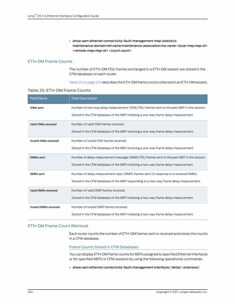
• show oam ethernet connectivity-fault-managementmep-statistics
maintenance-domainmd-namemaintenance-associationma-name<local-mepmep-id>
<remote-mepmep-id> <count count>
ETH-DM Frame Counts
The number of ETH-DM PDU frames exchanged in a ETH-DM session are stored in the
CFM database on each router.
Table 25 on page 254 describes the ETH-DM frame counts collected in an ETH-DM session.
Table 25: ETH-DM Frame Counts
Field DescriptionField Name
Number of one-way delay measurement (1DM) PDU frames sent to the peer MEP in this session.
Stored in the CFM database of the MEP initiating a one-way frame delay measurement.
1DMs sent
Number of valid 1DM frames received.
Stored in the CFM database of the MEP receiving a one-way frame delay measurement.
Valid 1DMs received
Number of invalid 1DM frames received.
Stored in the CFM database of the MEP receiving a one-way frame delay measurement.
Invalid 1DMs received
Number of delay measurement message (DMM) PDU frames sent to the peer MEP in this session.
Stored in the CFM database of the MEP initiating a two-way frame delay measurement.
DMMs sent
Number of delay measurement reply (DMR) frames sent (in response to a received DMM).
Stored in the CFM database of the MEP responding to a two-way frame delay measurement.
DMRs sent
Number of valid DMR frames received.
Stored in the CFM database of the MEP initiating a two-way frame delay measurement.
Valid DMRs received
Number of invalid DMR frames received.
Stored in the CFM database of the MEP initiating a two-way frame delay measurement.
Invalid DMRs received
ETH-DM Frame Count Retrieval
Each router counts the number of ETH-DM frames sent or received and stores the counts
in a CFM database.
Frame Counts Stored in CFMDatabases
You can display ETH-DM frame counts for MEPs assigned to specified Ethernet interfaces
or for specified MEPs in CFM sessions by using the following operational commands:
• show oam ethernet connectivity-fault-management interfaces (detail | extensive)
Copyright © 2011, Juniper Networks, Inc.254
Junos®
OS 11.4 Ethernet Interfaces Configuration Guide
• show oam ethernet connectivity-fault-managementmep-database
maintenance-domainmd-namemaintenance-associationma-name<local-mepmep-id>
<remote-mepmep-id>
One-Way ETH-DM Frame Counts
For a one-way ETH-DM session, delay statistics are collected at the receiver MEP only,
but frame counts are collected at both MEPs. As indicated in Table 25 on page 254, one-way
ETH-DM frame counts are tallied from the perspective of each router in the session:
• At the initiator MEP, the router counts the number of 1DM frames sent.
• At the receiver MEP, the router counts the number of valid 1DM frames received and
the number of invalid 1DM frames received.
You can also view one-way ETH-DM frame counts—for a receiver MEP—by using the
show oam ethernet connectivity-fault-managementmep-statistics command to display
one-way statistics and frame counts together.
Two-Way ETH-DM Frame Counts
For a two-way ETH-DM session, delay statistics are collected at the initiator MEP only,
but frame counts are collected at both MEPs. As indicated in Table 25 on page 254,
two-way ETH-DM frame counts are tallied from the perspective of each router in the
session:
• At the initiator MEP, the router counts the number of DMM frames sent, valid DMR
frames received, and invalid DMR frames received.
• At the responder MEP, the router counts the number of DMR frames sent.
You can also view two-way ETH-DM frame counts—for an initiator MEP—by using the
show oam ethernet connectivity-fault-managementmep-statistics command to display
two-way statistics and frame counts together.
RelatedDocumentation
Ethernet Frame Delay Measurements Overview on page 234•
• Managing ETH-DM Statistics and ETH-DM Frame Counts on page 261
• Example: One-Way Ethernet Frame Delay Measurement on page 271
• clear oam ethernet connectivity-fault-management statistics command
• show oam ethernet connectivity-fault-managementmep-statistics command
• show oam ethernet connectivity-fault-management delay-statistics command
• show oam ethernet connectivity-fault-management interfaces (detail | extensive)
command
• show oam ethernet connectivity-fault-managementmep-database command
• Junos OS Ethernet Interfaces Configuration Guide
255Copyright © 2011, Juniper Networks, Inc.
Chapter 14: Configuring ITU-T Y.1731 Ethernet Service OAM
Configuring Routers to Support an ETH-DMSession
• Configuring MEP Interfaces on page 256
• Ensuring That Distributed ppm Is Not Disabled on page 257
• Enabling the Hardware-Assisted Timestamping Option on page 258
• Configuring the Server-Side Processing Option on page 259
ConfiguringMEP Interfaces
Before you can start an Ethernet frame delay measurement session across an Ethernet
service, you must configure two MX Series routers to support ETH-DM.
To configure an Ethernet interface on a MX Series router to support ETH-DM:
1. On each router, configure two physical or logical Ethernet interfaces connected by aVLAN. The following configuration is typical for single-tagged logical interfaces:
[edit interfaces]interface {ethernet-interface-name {vlan-tagging;unit logical-unit-number {vlan-id vlan-id; # Both interfaces on this VLAN
}}
}
Both interfaces will use the same VLAN ID.
2. On each router, attach peer MEPs to the two interfaces. The following configurationis typical:
[edit protocols]oam {ethernet {connectivity-fault-management {maintenance-domainmd-name { # On both routerslevel number;maintenance-associationma-name { # On both routerscontinuity-check {interval 100ms;hold-interval 1;
}mepmep-id { # Attach to VLAN interfaceauto-discovery;direction (up | down);interface interface-name;priority number;
}}
}}
}}
Copyright © 2011, Juniper Networks, Inc.256
Junos®
OS 11.4 Ethernet Interfaces Configuration Guide

Ensuring That Distributed ppm Is Not Disabled
By default, the router’s period packet management process (ppm) runs sessions
distributed to the Packet Forwarding Engine in addition to the Routing Engine. This process
is responsible for periodic transmission of packets on behalf of its various client processes,
such as Bidirectional Forwarding Detection (BFD), and it also receives packets on behalf
of client processes.
In addition,ppmhandles time-sensitive periodic processing and performs such processes
as sending process-specific packets and gathering statistics. Withppmprocesses running
distributed on both the Routing Engine and the Packet Forwarding Engine, you can run
such processes as BFD on the Packet Forwarding Engine.
Distributed ppmRequired for ETH-DM
Ethernet frame delay measurement requires that ppm remains distributed to the PacketForwarding Engine. If ppm is not distributed to the Packet Forwarding Engines of bothrouters, ETH-DM PDU frame timestamps and ETH-DM statistics are not valid.
Before you start ETH-DM, you must verify that the following configuration statementis NOT present:
[edit]routing-options {ppm {no-delegate-processing;
}}
If distributed ppm processing is disabled (as shown in the stanza above) on either router,
you must re-enable it in order to use the ETH-DM feature.
Procedure to EnsurethatDistributedppmis
Not Disabled
To ensure that distributed ppm is not disabled on a router:
1. Display the packet processing management (PPM) configuration to determine whether
distributed ppm is disabled.
• In the following example, distributed ppm is enabled on the router. In this case, you
do not need to modify the router configuration:
[edit]user@host# show routing-optionsppm;
• In the following example, distributed ppm is disabled on the router. In this case,
you must proceed to Step 2 to modify the router configuration:
[edit]user@host show routing-optionsppm {no-delegate-processing;
}
257Copyright © 2011, Juniper Networks, Inc.
Chapter 14: Configuring ITU-T Y.1731 Ethernet Service OAM

2. Modify the router configuration to re-enable distributed ppm and restart the Ethernet
OAM Connectivity Fault Management process ONLY IF distributed ppm is disabled
(as determined in the previous step).
a. Before continuing, make any necessary preparations for the possible loss of
connectivity on the router.
Restarting the ethernet-connectivity-fault-management process has the following
effect on your network:
• All connectivity fault management (CFM) sessions re-establish.
• All ETH-DM requests on the router terminate.
• All ETH-DM statistics and frame counts reset to 0.
b. Modify the router configuration to re-enable distributed ppm. For example:
[edit]user@host# delete routing-options ppm no-delegate-processing
c. Commit the updated router configuration. For example:
[edit]user@host# commit and-quitcommit completeexiting configurationmode
d. To restart the Ethernet OAM Connectivity-Fault-Management process, enter the
restart ethernet-connectivity-fault-management <gracefully | immediately | soft>
operational mode command. For example:
user@host> restart ethernet-connectivity-fault-managementConnectivity fault management process started, pid 9893
Enabling the Hardware-Assisted Timestamping Option
By default, Ethernet frame delay measurement uses software for timestamping
transmitted and received ETH-DM frames. For Ethernet interfaces, you can optionally
use hardware timing to assist in the timestamping of received ETH-DM frames to increase
the accuracy of delay measurements.
Enabling hardware-assisted timestamping of received frames can increase the accuracy
of ETH-DM calculations when the DPC is loaded with heavy traffic in the receive direction.
To enable Ethernet frame delay measurement hardware assistance on the receptionpath, include the hardware-assisted-timestamping statement at the [edit protocols oamethernet connectivity-fault-management performance-monitoring] hierarchy level:
[edit protocols]oam {ethernet {connectivity-fault-management {performance-monitoring {hardware-assisted-timestamping;
}
Copyright © 2011, Juniper Networks, Inc.258
Junos®
OS 11.4 Ethernet Interfaces Configuration Guide

}}
}
Configuring the Server-Side Processing Option
You can delegate the server-side processing (for both two-way delay measurement and
loss measurement) to the Packet Forwarding Engine to prevent overloading on the
Routing Engine. By default, the server-side processing is done by the Routing Engine.
To configure the server-side processing option:
1. In configuration mode, go to the following hierarchy level:
user@host# edit protocols oam ethernet connectivity-fault-managementperformance-monitoring
2. Configure the server-side processing option.
[editprotocolsoamethernetconnectivity-fault-managementperformance-monitoring]user@host# set delegate-server-processing
3. Verify the configuration.
[edit protocols oam ethernet connectivity-fault-management]user@host# showperformance-monitoring {delegate-server-processing;
}
Starting an ETH-DMSession
• Using the monitor ethernet delay-measurement Command on page 259
• Starting a One-Way ETH-DM Session on page 260
• Starting a Two-Way ETH-DM Session on page 260
Using themonitor ethernet delay-measurement Command
After you have configured two MX Series routers to support ITU-T Y.1731 Ethernet frame
delay measurement (ETH-DM), you can initiate a one-way or two-way Ethernet frame
delay measurement session from the CFM maintenance association end point (MEP)
on one of the routers to the peer MEP on the other router.
To start an ETH-DM session between the specified local MEP and the specified remoteMEP, enter the monitor ethernet delay-measurement command at operational mode.The syntax of the command is as follows:
monitor ethernet delay-measurement(one-way | two-way)maintenance-domainmd-namemaintenance-associationma-name(remote-mac-address | mep remote-mep-id)<count frame-count><wait interval-seconds><priority 802.1p value><size>
259Copyright © 2011, Juniper Networks, Inc.
Chapter 14: Configuring ITU-T Y.1731 Ethernet Service OAM
<no-session-id-tlv><xml>
For a one-way frame delay measurement, the command displays a runtime display of
the number of 1DM frames sent from the initiator MEP during that ETH-DM session.
One-way frame delay and frame delay variation measurements from an ETH-DM session
are collected in a CFM database at the router that contains the receiver MEP. You can
retrieve ETH-DM statistics from a CFM database at a later time.
For a two-way frame delay measurement, the command displays two-way frame delay
and frame delay variation values for each round-trip frame exchange during that ETH-DM
session, as well as a runtime display of useful summary information about the session:
average delay, average delay variation, best-case delay, and worst-case delay. Two-way
frame delay and frame delay variation values measurements from an ETH-DM session
are collected in a CFM database at the router that contains the initiator MEP. You can
retrieve ETH-DM statistics from a CFM database at a later time.
NOTE: Although you can trigger frame delay collection for up to65,535 ETH-DM requests at a time, a router stores only the last 100 framedelay statistics per CFM session (pair of peer MEPs).
For a complete description of the monitor ethernet delay-measurement operational
command, see the Junos OS System Basics and Services Command Reference.
Starting a One-Way ETH-DMSession
To start a one-way Ethernet frame delay measurement session, enter themonitorethernet
delay-measurement one-way command from operational mode, and specify the peer
MEP by its MAC address or by its MEP identifier.
For example:
user@host> monitor ethernet delay-measurement one-way 00:05:85:73:39:4amaintenance-domainmd6maintenance-associationma6 count 10One-way ETH-DM request to 00:05:85:73:39:4a, Interface xe-5/0/0.01DM Frames sent : 10--- Delay measurement statistics ---Packets transmitted: 10Average delay: NA, Average delay variation: NABest case delay: NA, Worst case delay: NA
NOTE: If you attempt tomonitor delays to a nonexistent MAC address, youmust type Ctrl + C to explicitly quit themonitor ethernet delay-measurement
command and return to the CLI command prompt.
Starting a Two-Way ETH-DMSession
To start a two-way Ethernet frame delay measurement session, enter themonitorethernet
delay-measurement two-way command from operational mode, and specify the peer
MEP by its MAC address or by its MEP identifier.
Copyright © 2011, Juniper Networks, Inc.260
Junos®
OS 11.4 Ethernet Interfaces Configuration Guide

For example:
user@host> monitor ethernet delay-measurement two-way 00:05:85:73:39:4amaintenance-domainmd6maintenance-associationma6 count 10Two-way ETH-DM request to 00:05:85:73:39:4a, Interface xe-5/0/0.0DMR received from 00:05:85:73:39:4a Delay: 100 usec Delay variation: 0 usecDMR received from 00:05:85:73:39:4a Delay: 92 usec Delay variation: 8 usecDMR received from 00:05:85:73:39:4a Delay: 92 usec Delay variation: 0 usecDMR received from 00:05:85:73:39:4a Delay: 111 usec Delay variation: 19 usecDMR received from 00:05:85:73:39:4a Delay: 110 usec Delay variation: 1 usecDMR received from 00:05:85:73:39:4a Delay: 119 usec Delay variation: 9 usecDMR received from 00:05:85:73:39:4a Delay: 122 usec Delay variation: 3 usecDMR received from 00:05:85:73:39:4a Delay: 92 usec Delay variation: 30 usecDMR received from 00:05:85:73:39:4a Delay: 92 usec Delay variation: 0 usecDMR received from 00:05:85:73:39:4a Delay: 108 usec Delay variation: 16 usec
--- Delay measurement statistics ---Packets transmitted: 10, Valid packets received: 10Average delay: 103 usec, Average delay variation: 8 usecBest case delay: 92 usec, Worst case delay: 122 usec
NOTE: If you attempt tomonitor delays to a nonexistent MAC address, youmust type Ctrl + C to explicitly quit themonitor ethernet delay-measurement
command and return to the CLI command prompt.
RelatedDocumentation
Ethernet Frame Delay Measurements Overview on page 234•
• Guidelines for Starting an ETH-DM Session on page 249
• monitor ethernet delay-measurement command
• Guidelines for Managing ETH-DM Statistics and ETH-DM Frame Counts on page 252
• Managing ETH-DM Statistics and ETH-DM Frame Counts on page 261
• Junos OS Ethernet Interfaces Configuration Guide
Managing ETH-DMStatistics and ETH-DM Frame Counts
• Displaying ETH-DM Statistics Only on page 261
• Displaying ETH-DM Statistics and Frame Counts on page 262
• Displaying ETH-DM Frame Counts for MEPs by Enclosing CFM Entity on page 262
• Displaying ETH-DM Frame Counts for MEPs by Interface or Domain Level on page 263
• Clearing ETH-DM Statistics and Frame Counts on page 264
Displaying ETH-DMStatistics Only
Purpose Display ETH-DM statistics.
By default, the show oam ethernet connectivity-fault-management delay-statistics
command displays ETH-DM statistics for MEPs in the specified CFM maintenance
association (MA) within the specified CFM maintenance domain (MD).
261Copyright © 2011, Juniper Networks, Inc.
Chapter 14: Configuring ITU-T Y.1731 Ethernet Service OAM

Action To display the ETH-DM statistics collected for MEPs belonging to MA ma1 and within
MD md1:
•
user@host> show oam ethernet connectivity-fault-management delay-statisticsmaintenance-domainma1maintenance-associationma1
• To display the ETH-DM statistics collected for ETH-DM sessions for the local MEP 201
belonging to MA ma2 and within MD md2:
user@host> show oam ethernet connectivity-fault-management delay-statisticsmaintenance-domainmd2maintenance-associationma2 local-mep 201
• To display the ETH-DM statistics collected for ETH-DM sessions from local MEPs
belonging to MA ma3 and within MD md3 to remote MEP 302:
user@host> show oam ethernet connectivity-fault-management delay-statisticsmaintenance-domainmd3maintenance-associationma3 remote-mep 302
Displaying ETH-DMStatistics and Frame Counts
Purpose Display ETH-DM statistics and ETH-DM frame counts.
By default, the show oam ethernet connectivity-fault-managementmep-statistics
command displays ETH-DM statistics and frame counts for MEPs in the specified CFM
maintenance association (MA) within the specified CFM maintenance domain (MD).
Action To display the ETH-DM statistics and ETH-DM frame counts for MEPs in MA ma1 and
within MD md1:
•
user@host> show oam ethernet connectivity-fault-managementmep-statisticsmaintenance-domainmd1maintenance-associationma1
• To display the ETH-DM statistics and ETH-DM frame counts for the local MEP 201 in
MA ma2 and within MD md2:
user@host> show oam ethernet connectivity-fault-managementmep-statisticsmaintenance-domainmd2maintenance-associationma2 local-mep 201
• To display the ETH-DM statistics and ETH-DM frame counts for the local MEP in
MD md3 and within MA ma3 that participates in an ETH-DM session with the remote
MEP 302:
user@host> show oam ethernet connectivity-fault-managementmep-statisticsmaintenance-domainma3maintenance-associationma3 remote-mep 302
Displaying ETH-DM Frame Counts for MEPs by Enclosing CFM Entity
Purpose Display ETH-DM frame counts for CFM maintenance association end points (MEPs).
By default, the show oam ethernet connectivity-fault-managementmep-database
command displays CFM database information for MEPs in the specified CFM maintenance
association (MA) within the specified CFM maintenance domain (MD).
Copyright © 2011, Juniper Networks, Inc.262
Junos®
OS 11.4 Ethernet Interfaces Configuration Guide

NOTE: At the router attached to the initiator MEP for a one-way session, orat the router attached to the receiver MEP for a two-way session, you canonly display ETH-DM frame counts.
Action To display CFM database information (including ETH-DM frame counts) for all MEPs
in MA ma1 within MD md1:
•
user@host> show oam ethernet connectivity-fault-managementmep-databasemaintenance-domainma1maintenance-associationma1
• To display CFM database information (including ETH-DM frame counts) only for local
MEP 201 in MA ma1 within MD md1:
user@host> show oam ethernet connectivity-fault-managementmep-databasemaintenance-domainmd2maintenance-associationma2 local-mep 201
• To display CFM database information (including ETH-DM frame counts) only for remote
MEP 302 in MD md3 within MA ma3:
user@host> show oam ethernet connectivity-fault-managementmep-databasemaintenance-domainma3maintenance-associationma3 remote-mep 302
Displaying ETH-DM Frame Counts for MEPs by Interface or Domain Level
Purpose Display ETH-DM frame counts for CFM maintenance association end points (MEPs).
By default, the show oam ethernet connectivity-fault-management interfaces command
displays CFM database information for MEPs attached to CFM-enabled Ethernet
interfaces on the router or at a maintenance domain level. For Ethernet interfaces that
support ETH-DM, any frame counts are also displayed when you specify the detail or
extensive command option.
NOTE: At the router attached to the initiator MEP for a one-way session, orat the router attached to the receiver MEP for a two-way session, you canonly display ETH-DM frame counts.
Action To display CFM database information (including ETH-DM frame counts) for all MEPs
attached to CFM-enabled Ethernet interfaces on the router:
•
user@host> show oam ethernet connectivity-fault-management interfaces detail
• To display CFM database information (including ETH-DM frame counts) only for the
MEPs attached to CFM-enabled router interface ge-5/2/9.0:
user@host> showoamethernetconnectivity-fault-management interfacesge-5/2/9.0detail
263Copyright © 2011, Juniper Networks, Inc.
Chapter 14: Configuring ITU-T Y.1731 Ethernet Service OAM

• To display CFM database information (including ETH-DM frame counts) only for MEPs
enclosed within CFM maintenance domains (MDs) at level 6:
user@host> show oam ethernet connectivity-fault-management interfaces level 6detail
Clearing ETH-DMStatistics and Frame Counts
Purpose Clear the ETH-DM statistics and ETH-DM frame counts.
By default, statistics and frame counts are deleted for all MEPs attached to CFM-enabled
interfaces on the router. However, you can filter the scope of the command by specifying
an interface name.
Action To clear the ETH-DM statistics and ETH-DM frame counts for all MEPs attached to
CFM-enabled interfaces on the router:
•
user@host> clear oam ethernet connectivity-fault-management statistics
• To clear the ETH-DM statistics and ETH-DM frame counts only for MEPs attached to
the logical interface ge-0/5.9.0:
user@host> clear oam ethernet connectivity-fault-management statistics ge-0/5/9.0
RelatedDocumentation
clear oam ethernet connectivity-fault-management statistic command•
• show oam ethernet connectivity-fault-management delay-statistics command
• show oam ethernet connectivity-fault-management interfaces (detail | extensive)
command
• show oam ethernet connectivity-fault-managementmep-statistics command
• show oam ethernet connectivity-fault-managementmep-database command
• Junos OS Ethernet Interfaces Configuration Guide
Managing ETH-LM Statistics
• Displaying ETH-LM Statistics on page 264
• Clearing ETH-LM Statistics on page 265
Displaying ETH-LM Statistics
Purpose Display the ETH-LM statistics.
By default, the show oam ethernet connectivity-fault-management loss-statistics
maintenance-domainmd-namemaintenance-associationma-name command displays
ETH-LM statistics for MEPs in the specified CFM maintenance association (MA) within
the specified CFM maintenance domain (MD).
Copyright © 2011, Juniper Networks, Inc.264
Junos®
OS 11.4 Ethernet Interfaces Configuration Guide
The following list consists of the CFM-related operational mode commands that have
been enhanced to display ETH-LM statistics:
• The show oam ethernet connectivity-fault-management interfaces detail command is
enhanced to display ETH-DM and ETH-LM statistics for MEPs in the specified CFM
maintenance association (MA) within the specified CFM maintenance domain (MD).
• The show oam ethernet connectivity-fault-managementmep-statistics command is
enhanced to display ETH-DM and ETH-LM statistics and frame counts for MEPs in the
specified CFM maintenance association (MA) within the specified CFM maintenance
domain (MD).
• The show oam ethernet connectivity-fault-managementmep-database command is
enhanced to display ETH-DM and ETH-LM frame counters for MEPs in the specified
CFM maintenance association (MA) within the specified CFM maintenance domain
(MD).
Action To display the ETH-LM statistics for all MEPs attached to CFM-enabled interfaces on
the router:
•
user@host> show oam ethernet connectivity-fault-management loss-statistics
• To display the ETH-DM statistics collected for MEPs belonging to MA ma1 and within
MD md1:
user@host> show oam ethernet connectivity-fault-management delay-statisticsmaintenance-domainmd1maintenance-associationma1
• To display the ETH-DM statistics and ETH-DM frame counts for MEPs in MA ma1 and
within MD md1:
user@host> show oam ethernet connectivity-fault-managementmep-statisticsmaintenance-domainmd1maintenance-associationma1
• To display CFM database information (including ETH-DM frame counts) for all MEPs
in MA ma1 within MD md1:
user@host> show oam ethernet connectivity-fault-managementmep-databasemaintenance-domainmd1maintenance-associationma1
Clearing ETH-LM Statistics
Purpose Clear the ETH-LM statistics.
By default, statistics are deleted for all MEPs attached to CFM-enabled interfaces on
the router. However, you can filter the scope of the command by specifying an interface
name.
Action To clear the ETH-LM statistics for all MEPs attached to CFM-enabled interfaces on
the router:
•
user@host> clear oam ethernet connectivity-fault-management loss-statistics
265Copyright © 2011, Juniper Networks, Inc.
Chapter 14: Configuring ITU-T Y.1731 Ethernet Service OAM

RelatedDocumentation
Managing ETH-DM Statistics and ETH-DM Frame Counts on page 261•
Managing Iterator Statistics
• Displaying Iterator Statistics on page 266
• Clearing Iterator Statistics on page 270
Displaying Iterator Statistics
Purpose Retrieve and display iterator statistics.
Muliple iterators can be associated with a remote MEP. However, by default, only one
result pertaining to one iterator profile is displayed.
Action To display the iterator statistics for remote MEP 1 and iterator profile i1 with MEPs
belonging to the maintenance association ma1 and within the maintenance domain
default-1 (here, the iterator profile i1 is configured for two-way delay measurement):
•
user@host> showoamethernet connectivity-fault-management sla-iterator-statisticssla-iterator i1 maintenance-domain default-1 maintenance-associationma1 local-mep1 remote-mep 1
Iterator statistics:Maintenance domain: md6, Level: 6Maintenance association: ma6, Local MEP id: 1000Remote MEP id: 103, Remote MAC address: 00:90:69:0a:43:92Iterator name: i1, Iterator Id: 1Iterator cycle time: 10ms, Iteration period: 1 cyclesIterator status: running, Infinite iterations: trueCounter reset time: 2010-03-19 20:42:39 PDT (2d 18:24 ago)Reset reason: Adjacency flap
Iterator delay measurement statistics:Delay weight: 1, Delay variation weight: 1DMM sent : 23898520DMM skipped for threshold hit : 11000DMM skipped for threshold hit window : 0DMR received : 23851165DMR out of sequence : 1142DMR received with invalid time stamps : 36540Average two-way delay : 129 usecAverage two-way delay variation : 15 usecAverage one-way forward delay variation : 22 usecAverage one-way backward delay variation : 22 usecWeighted average two-way delay : 134 usecWeighted average two-way delay variation : 8 usecWeighted average one-way forward delay variation : 6 usecWeighted average one-way backward delay variation : 2 usec
Output fields are listed in the approximate order in which they appear.
Table 26: Displaying Iterator Statistics for Ethernet DelayMeasurement Output Fields
Output Field DescriptionOutput Field Name
Maintenance domain name.Maintenance domain
Copyright © 2011, Juniper Networks, Inc.266
Junos®
OS 11.4 Ethernet Interfaces Configuration Guide
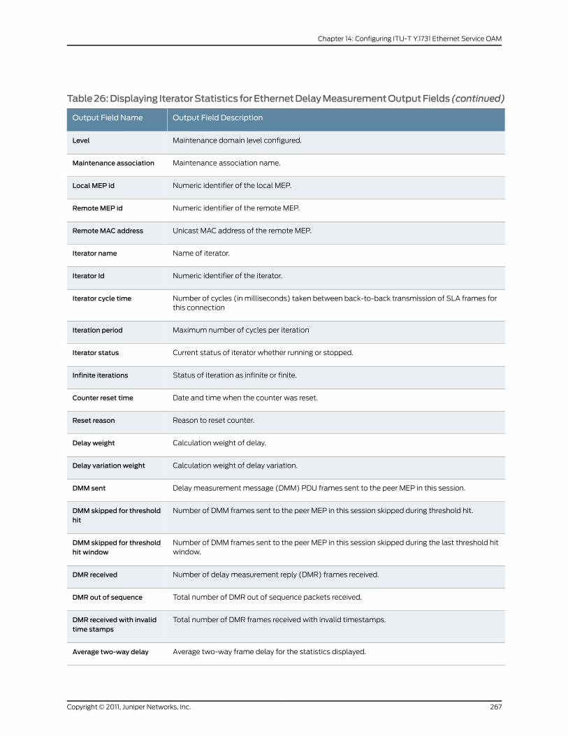
Table26:Displaying IteratorStatistics forEthernetDelayMeasurementOutputFields(continued)
Output Field DescriptionOutput Field Name
Maintenance domain level configured.Level
Maintenance association name.Maintenance association
Numeric identifier of the local MEP.Local MEP id
Numeric identifier of the remote MEP.RemoteMEP id
Unicast MAC address of the remote MEP.RemoteMAC address
Name of iterator.Iterator name
Numeric identifier of the iterator.Iterator Id
Number of cycles (in milliseconds) taken between back-to-back transmission of SLA frames forthis connection
Iterator cycle time
Maximum number of cycles per iterationIteration period
Current status of iterator whether running or stopped.Iterator status
Status of iteration as infinite or finite.Infinite iterations
Date and time when the counter was reset.Counter reset time
Reason to reset counter.Reset reason
Calculation weight of delay.Delay weight
Calculation weight of delay variation.Delay variation weight
Delay measurement message (DMM) PDU frames sent to the peer MEP in this session.DMM sent
Number of DMM frames sent to the peer MEP in this session skipped during threshold hit.DMM skipped for thresholdhit
Number of DMM frames sent to the peer MEP in this session skipped during the last threshold hitwindow.
DMM skipped for thresholdhit window
Number of delay measurement reply (DMR) frames received.DMR received
Total number of DMR out of sequence packets received.DMR out of sequence
Total number of DMR frames received with invalid timestamps.DMR receivedwith invalidtime stamps
Average two-way frame delay for the statistics displayed.Average two-way delay
267Copyright © 2011, Juniper Networks, Inc.
Chapter 14: Configuring ITU-T Y.1731 Ethernet Service OAM

Table26:Displaying IteratorStatistics forEthernetDelayMeasurementOutputFields(continued)
Output Field DescriptionOutput Field Name
Average two-way “frame jitter” for the statistics displayed.Average two-way delayvariation
Average one-way forward delay variation for the statistics displayed in microseconds.Average one-way forwarddelay variation
Average one-way backward delay variation for the statistics displayed in microseconds.Average one-way backwarddelay variation
Weighted average two-way delay for the statistics displayed in microseconds.Weighted average two-waydelay
Weighted average two-way delay variation for the statistics displayed in microseconds.Weighted average two-waydelay variation
Weighted average one-way forward delay variation for the statistics displayed in microseconds.Weighted average one-wayforward delay variation
Weighted average one-way backward delay variation for the statistics displayed in microseconds.Weighted average one-waybackward delay variation
• To display the iterator statistics for remote MEP 1 and iterator profile i2 with MEPs
belonging to the maintenance association ma1 and within the maintenance domain
default-1 (here, the iterator profile i1 is configured for loss measurement):
user@host> showoamethernet connectivity-fault-management sla-iterator-statisticssla-iterator i2maintenance-domain default-1 maintenance-associationma1 local-mep1 remote-mep 1
Iterator statistics:Maintenance domain: md6, Level: 6Maintenance association: ma6, Local MEP id: 1000Remote MEP id: 103, Remote MAC address: 00:90:69:0a:43:92Iterator name: i2, Iterator Id: 2Iterator cycle time: 1000ms, Iteration period: 2000 cyclesIterator status: running, Infinite iterations: trueCounter reset time: 2010-03-19 20:42:39 PDT (2d 18:25 ago)Reset reason: Adjacency flap
Iterator loss measurement statistics:LMM sent : 238970LMM skipped for threshold hit : 60LMM skipped for threshold hit window : 0LMR received : 238766LMR out of sequence : 43
Accumulated transmit statistics:Near-end (CIR) : 0Far-end (CIR) : 0Near-end (EIR) : 0Far-end (EIR) : 0
Accumulated loss statistics:
Copyright © 2011, Juniper Networks, Inc.268
Junos®
OS 11.4 Ethernet Interfaces Configuration Guide

Near-end (CIR) : 0 (0.00%)Far-end (CIR) : 0 (0.00%)Near-end (EIR) : 0 (0.00%)Far-end (EIR) : 0 (0.00%)
Last loss measurement statistics:Near-end (CIR) : 0Far-end (CIR) : 0Near-end (EIR) : 0Far-end (EIR) : 0
Output fields are listed in the approximate order in which they appear.
Table 27: Displaying Iterator Statistics for Ethernet LossMeasurement Output Fields
Output Field DescriptionOutput Field Name
Maintenance domain name.Maintenance domain
Maintenance domain level configured.Level
Maintenance association name.Maintenance association
Numeric identifier of the local MEP.Local MEP id
Numeric identifier of the remote MEP.RemoteMEP identifier
Unicast MAC address of the remote MEP.RemoteMAC address
Name of iterator.Iterator name
Numeric identifier of the iterator.Iterator Id
Number of cycles (in milliseconds) taken between back-to-back transmission of SLA frames forthis connection
Iterator cycle time
Maximum number of cycles per iterationIteration period
Current status of iterator whether running or stopped.Iterator status
Status of iteration as infinite or finite.Infinite iterations
Date and time when the counter was reset.Counter reset time
Reason to reset counter.Reset reason
Number of loss measurement message (LMM) PDU frames sent to the peer MEP in this session.LMM sent
Number of LMM frames sent to the peer MEP in this session skipped during threshold hit.LMM skipped for thresholdhit
Number of LMM frames sent to the peer MEP in this session skipped during the last threshold hitwindow.
LMM skipped for thresholdhit window
269Copyright © 2011, Juniper Networks, Inc.
Chapter 14: Configuring ITU-T Y.1731 Ethernet Service OAM

Table27:Displaying IteratorStatistics forEthernetLossMeasurementOutputFields (continued)
Output Field DescriptionOutput Field Name
Number of LMRs frames received.LMR received
Total number of LMR out of sequence packets received.LMR out of sequence
Frame loss associated with ingress data frames for the statistics displayed.Near-end (CIR)
Frame loss associated with egress data frames for the statistics displayed.Far-end (CIR)
Frame loss associated with ingress data frames for the statistics displayed.Near-end (EIR)
Frame loss associated with egress data frames for the statistics displayed.Far-end (EIR)
Clearing Iterator Statistics
Purpose Clear iterator statistics.
Multiple iterators can be associated with remote MEP. However, by default, only one
result pertaining to one iterator profile can be cleared.
Action To clear the iterator statistics for remote MEP 1 and iterator profile i1 with MEPs
belonging to the maintenance association ma1 and within the maintenance domain
default-1:
•
user@host> clear oam ethernet connectivity-fault-management sla-iterator-statisticssla-iterator i1 maintenance-domain default-1 maintenance-associationma1 local-mep1 remote-mep 1
• To clear the iterator statistics for remote MEP 1 and iterator profile i2 with MEPs
belonging to the maintenance association ma1 and within the maintenance
domain default-1:
user@host> clear oam ethernet connectivity-fault-management sla-iterator-statisticssla-iterator i2maintenance-domain default-1 maintenance-associationma1 local-mep1 remote-mep 1
RelatedDocumentation
Configuring an Iterator Profile on page 244•
• Configuring a Remote MEP with an Iterator Profile on page 246
• Example: Configuring an Iterator on page 278
• Proactive Mode on page 242
Managing Continuity Measurement Statistics
• Displaying Continuity Measurement Statistics on page 271
• Clearing Continuity Measurement Statistics on page 271
Copyright © 2011, Juniper Networks, Inc.270
Junos®
OS 11.4 Ethernet Interfaces Configuration Guide

Displaying Continuity Measurement Statistics
Purpose Display continuity measurement.
The show oam ethernet connectivity-fault-management delay-statistics
maintenance-domainmd1maintenance-associationma1command is enhanced to display
continuity measurement statistics for MEPs in the specified CFM maintenance association
(MA) within the specified CFM maintenance domain (MD).
Action To display the ETH-DM statistics collected for MEPs belonging to MA ma1 and within
MD md1:
•
user@host> show oam ethernet connectivity-fault-management delay-statisticsmaintenance-domainmd1maintenance-associationma1
Clearing Continuity Measurement Statistics
Purpose Clear the continuity measurement statistics
By default, statistics are deleted for all MEPs attached to CFM-enabled interfaces on
the router. However, you can filter the scope of the command by specifying an interface
name.
Action To clear the continuity measurement statistics for all MEPs attached to CFM-enabled
interfaces on the router:
•
user@host> clearoamethernetconnectivity-fault-managementcontinuity-measurementmaintenance-domainmd-namemaintenance-associationma-name local-meplocal-mep-id remote-mep remote-mep-id
Example: One-Way Ethernet Frame DelayMeasurement
• Description of the One-Way Frame Delay Measurement Example on page 271
• Steps for the One-Way Frame Delay Measurement Example on page 273
Description of the One-Way Frame DelayMeasurement Example
This example shows how you can configure two MX Series routers (MX-PE1andMX-PE2)
to support an ETH-DM session between two peer MEPs (MEP 201 and MEP 101), initiate
a one-way ETH-DM session (from MEP 101 to MEP 201), and then display the ETH-DM
statistics and frame counts collected. To increase the accuracy of the ETH-DM statistics,
enable optional hardware-assisted timestamping of received ETH-DM frames on the
router that contains the receiver MEP.
271Copyright © 2011, Juniper Networks, Inc.
Chapter 14: Configuring ITU-T Y.1731 Ethernet Service OAM

Routers Used in This Example
To support one-way ETH-DM with optional hardware timestamping of frames on the
reception path, the routers used in this example are configured as follows:
• Routers MX-PE1 and MX-PE2 are MX Series routers.
• The system clocks of routers MX-PE1 and MX-PE2 are closely synchronized.
• On router MX-PE1, interface ge-5/2/9 is an Ethernet port. The traffic load received is
heavy.
• On router MX-PE2, interface ge-0/2/5 is an Ethernet port.
ETH-DM Frame Counts for this Example
Both routers count the number of ETH-DM frames sent and received by the peer MEPs
in the session and store the frame counts in the CFM databases as follows:
• At router MX-PE2, which contains the initiator MEP 101, the CFM database stores the
ETH-DM frame counts for a one-way ETH-DM initiator (the count of 1DM frames sent).
• At router MX-PE1, which contains the receiver MEP 201, the CFM database stores the
ETH-DM frame counts for a one-way ETH-DM receiver (the count of valid 1DM frames
received and the count of invalid 1DM frames received).
ETH-DMStatistics for this Example
For a one-way frame delay measurement, only the router that contains the receiver MEP
measures and stores frame delay statistics. In this example, ETH-DM statistics collected
for the session are available only at router MX-PE1.
Copyright © 2011, Juniper Networks, Inc.272
Junos®
OS 11.4 Ethernet Interfaces Configuration Guide

Steps for the One-Way Frame DelayMeasurement Example
The following steps describe an example one-way Ethernet frame delay measurement:
1. At router MX-PE1, configure MEP 201 as a CFM maintenance association endpoint in
CFM maintenance domain md6 as follows:
a. Define the maintenance domain md6 by associating it with maintenance domain
level 6 and maintenance association identifier ma6.
b. Configure the maintenance association by specifying continuity protocol options
and specifying MEP identifier 201.
c. Configure MEP 201 by attaching it to logical interface ge-5/2/9.0, which is a
single-tag interface on VLAN 512.
The following configuration is only a partial example of a complete and functionalrouter configuration:
[edit]interfaces { # Configure a single-tag logical interface on VLAN 512ge-5/2/9 {vlan-tagging;unit 0 {vlan-id 512;
}}
}protocols {oam {ethernet {connectivity-fault-management {traceoptions {file eoam_cfm.log size 1g files 2 world-readable;flag all;
}maintenance-domainmd6 { # Define MD ’md6’ on router MX-PE1level 6;maintenance-associationma6 { # Configure MA ’ma6’ on router MX-PE1continuity-check {interval 100ms;hold-interval 1;
}mep 201 { # Configure MEP 201 on router MX-PE1interface ge-5/2/9.0; # Attach to logical interface on VLAN 512direction down;auto-discovery;
}}
}}
}}
}
273Copyright © 2011, Juniper Networks, Inc.
Chapter 14: Configuring ITU-T Y.1731 Ethernet Service OAM

2. At router MX-PE2, configure MEP 101 as a CFM maintenance association endpoint in
CFM maintenance domain md6 as follows:
a. Define the maintenance domain md6 by associating it with maintenance domain
level 6 and maintenance association identifier ma6.
b. Configure the maintenance association by specifying continuity protocol options
and specifying MEP identifier 101.
c. Configure MEP 101 by attaching it to logical interface ge-0/2/5.0, which is a
single-tag interface on VLAN 512.
The following configuration is only a partial example of a complete and functionalconfiguration for router MX-PE2:
[edit]interfaces { # Configure a single-tag logical interface on VLAN 512ge-0/2/5 {vlan-tagging;unit 0 {vlan-id 512;
}}
}protocols {oam {ethernet {connectivity-fault-management {traceoptions {file eoam_cfm.log size 1g files 2 world-readable;flag all;
}maintenance-domainmd6 { # Define MD ’md6’ on router MX-PE2level 6;maintenance-associationma6 { # Configure MA ’ma6’ on router MX-PE2continuity-check {interval 100ms;hold-interval 1;
}mep 101 { # Configure MEP 101 on router MX-PE2interface ge–0/2/5.0; # Attach to logical interface on VLAN 512direction down;auto-discovery;
}}
}}
}}
3. (Optional) To increase the accuracy of the ETH-DM statistics, modify the configurationof router MX-PE1, which contains the receiver MEP, by enabling hardware-assistedtimestamping of 1DM frames received on the router.
[edit protocols]oam {
Copyright © 2011, Juniper Networks, Inc.274
Junos®
OS 11.4 Ethernet Interfaces Configuration Guide

ethernet {connectivity-fault-management {performance-monitoring {hardware-assisted-timestamping;
}}
}}
4. At router MX-PE2, start a one-way frame delay measurement session from local
MEP 101 to remote MEP 201 on router MX-PE1:
user@MX-PE2> monitor ethernet delay-measurement one-waymep 201maintenance-domainmd6maintenance-associationma6 count 10
One-way ETH-DM request to 00:90:69:0a:43:94, Interface ge-0/2/5.01DM Frames sent : 10--- Delay measurement statistics ---Packets transmitted: 10Average delay: NA, Average delay variation: NABest case delay: NA, Worst case delay: NA
5. At router MX-PE2, which contains the initiator MEP, only the ETH-DM frame counts
are available. Furthermore, the only frame count tallied for the initiator of a one-way
frame delay measurement is the count of 1DM frames transmitted.
ETH-DM frame counts (the number of 1DM, DMM, and DMR frames exchanged during
an ETH-DM session) are stored in the CFM database of both the initiator and receiver
MEPs. When you display CFM database information, you can also display the ETH-DM
frame counts. You can display CFM database information for all interfaces on the
router, or you can limit the output to MEPs associated with certain CFM MDs and MAs.
• To display CFM database information for MEPs specified by enclosing CFM entities,
use themep-database form of theshowoamethernetconnectivity-fault-management
command. A CFM database also stores any ETH-DM frame counts.
In the example configuration for router MX-PE2, MEP 101 is the only MEP defined in
MA ma6 within MD md6. Therefore, the show oam ethernet connectivity-fault
managementmep-database command output displays CFM database information
for MEP 101 only, even though you do not filter the command output by including
the local-mep or remote-mep command options.
user@MX-PE2> show oam ethernet connectivity-fault-managementmep-databasemaintenance-domainmd6maintenance-associationma6
Maintenance domain name: md6, Format: string, Level: 6 Maintenance association name: ma6, Format: string Continuity-check status: enabled, Interval: 100ms, Loss-threshold: 3 frames MEP identifier: 101, Direction: down, MAC address: 00:90:69:0a:48:57 Auto-discovery: enabled, Priority: 0 Interface name: ge-0/2/5.0, Interface status: Active, Link status: Up Defects: Remote MEP not receiving CCM : no Erroneous CCM received : no Cross-connect CCM received : no RDI sent by some MEP : no Statistics: CCMs sent : 1590
275Copyright © 2011, Juniper Networks, Inc.
Chapter 14: Configuring ITU-T Y.1731 Ethernet Service OAM

CCMs received out of sequence : 0 LBMs sent : 0 Valid in-order LBRs received : 0 Valid out-of-order LBRs received : 0 LBRs received with corrupted data : 0 LBRs sent : 0 LTMs sent : 0 LTMs received : 0 LTRs sent : 0 LTRs received : 0 Sequence number of next LTM request : 0 1DMs sent : 10 Valid 1DMs received : 0 Invalid 1DMs received : 0 DMMs sent : 0 DMRs sent : 0 Valid DMRs received : 0 Invalid DMRs received : 0 Remote MEP count: 1 Identifier MAC address State Interface 201 00:90:69:0a:43:94 ok ge-0/2/5.0
• To display CFM database information for MEPs specified by interface name, use
the interfaces detail form of the showoamethernet connectivity-fault-management
command. A CFM database also stores any ETH-DM frame counts.
In the example configuration for router MX-PE2, MEP 101 is the only MEP assigned
to an interface on the router. Therefore, the show oam ethernet
connectivity-fault-management interfaces (detail | extensive) command output
displays CFM database information for MEP 101 only, even though you do not filter
the command output by including the ethernet-interface-name or levelmd-level
command options.
user@MX-PE2> show oam ethernet connectivity-fault-management interfaces detail
Interface name: ge-0/2/5.0, Interface status: Active, Link status: Up Maintenance domain name: md6, Format: string, Level: 6 Maintenance association name: ma6, Format: string Continuity-check status: enabled, Interval: 100ms, Loss-threshold: 3 frames MEP identifier: 101, Direction: down, MAC address: 00:90:69:0a:48:57 MEP status: running Defects: Remote MEP not receiving CCM : no Erroneous CCM received : no Cross-connect CCM received : no RDI sent by some MEP : no Statistics: CCMs sent : 1590 CCMs received out of sequence : 0 LBMs sent : 0 Valid in-order LBRs received : 0 Valid out-of-order LBRs received : 0 LBRs received with corrupted data : 0 LBRs sent : 0 LTMs sent : 0 LTMs received : 0 LTRs sent : 0 LTRs received : 0 Sequence number of next LTM request : 0
Copyright © 2011, Juniper Networks, Inc.276
Junos®
OS 11.4 Ethernet Interfaces Configuration Guide
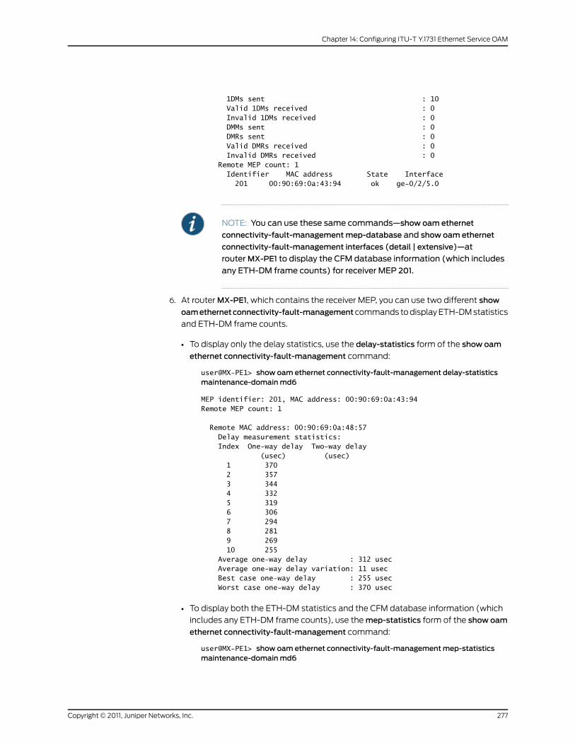
1DMs sent : 10 Valid 1DMs received : 0 Invalid 1DMs received : 0 DMMs sent : 0 DMRs sent : 0 Valid DMRs received : 0 Invalid DMRs received : 0 Remote MEP count: 1 Identifier MAC address State Interface 201 00:90:69:0a:43:94 ok ge-0/2/5.0
NOTE: You can use these same commands—show oam ethernet
connectivity-fault-managementmep-database and show oam ethernet
connectivity-fault-management interfaces (detail | extensive)—at
routerMX-PE1 to display the CFM database information (which includes
any ETH-DM frame counts) for receiver MEP 201.
6. At router MX-PE1, which contains the receiver MEP, you can use two different show
oamethernetconnectivity-fault-managementcommands to display ETH-DM statistics
and ETH-DM frame counts.
• To display only the delay statistics, use the delay-statistics form of the show oam
ethernet connectivity-fault-management command:
user@MX-PE1> show oam ethernet connectivity-fault-management delay-statisticsmaintenance-domainmd6
MEP identifier: 201, MAC address: 00:90:69:0a:43:94Remote MEP count: 1
Remote MAC address: 00:90:69:0a:48:57 Delay measurement statistics: Index One-way delay Two-way delay (usec) (usec) 1 370 2 357 3 344 4 332 5 319 6 306 7 294 8 281 9 269 10 255 Average one-way delay : 312 usec Average one-way delay variation: 11 usec Best case one-way delay : 255 usec Worst case one-way delay : 370 usec
• To display both the ETH-DM statistics and the CFM database information (which
includes any ETH-DM frame counts), use the mep-statistics form of the show oam
ethernet connectivity-fault-management command:
user@MX-PE1> show oam ethernet connectivity-fault-managementmep-statisticsmaintenance-domainmd6
277Copyright © 2011, Juniper Networks, Inc.
Chapter 14: Configuring ITU-T Y.1731 Ethernet Service OAM
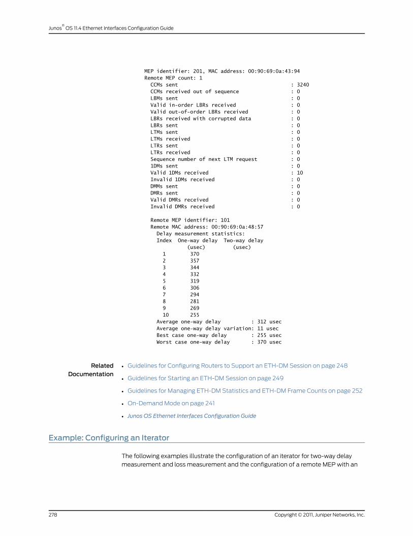
MEP identifier: 201, MAC address: 00:90:69:0a:43:94Remote MEP count: 1 CCMs sent : 3240 CCMs received out of sequence : 0 LBMs sent : 0 Valid in-order LBRs received : 0 Valid out-of-order LBRs received : 0 LBRs received with corrupted data : 0 LBRs sent : 0 LTMs sent : 0 LTMs received : 0 LTRs sent : 0 LTRs received : 0 Sequence number of next LTM request : 0 1DMs sent : 0 Valid 1DMs received : 10 Invalid 1DMs received : 0 DMMs sent : 0 DMRs sent : 0 Valid DMRs received : 0 Invalid DMRs received : 0
Remote MEP identifier: 101 Remote MAC address: 00:90:69:0a:48:57 Delay measurement statistics: Index One-way delay Two-way delay (usec) (usec) 1 370 2 357 3 344 4 332 5 319 6 306 7 294 8 281 9 269 10 255 Average one-way delay : 312 usec Average one-way delay variation: 11 usec Best case one-way delay : 255 usec Worst case one-way delay : 370 usec
RelatedDocumentation
Guidelines for Configuring Routers to Support an ETH-DM Session on page 248•
• Guidelines for Starting an ETH-DM Session on page 249
• Guidelines for Managing ETH-DM Statistics and ETH-DM Frame Counts on page 252
• On-Demand Mode on page 241
• Junos OS Ethernet Interfaces Configuration Guide
Example: Configuring an Iterator
The following examples illustrate the configuration of an iterator for two-way delay
measurement and loss measurement and the configuration of a remote MEP with an
Copyright © 2011, Juniper Networks, Inc.278
Junos®
OS 11.4 Ethernet Interfaces Configuration Guide
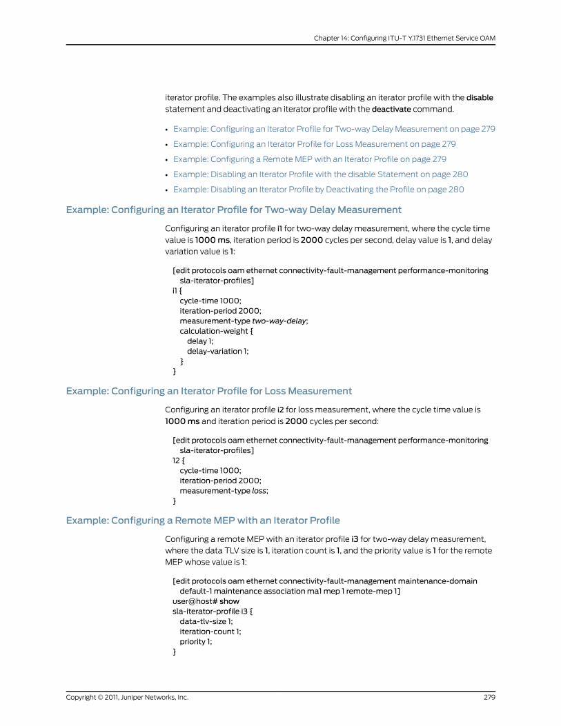
iterator profile. The examples also illustrate disabling an iterator profile with the disable
statement and deactivating an iterator profile with the deactivate command.
• Example: Configuring an Iterator Profile for Two-way Delay Measurement on page 279
• Example: Configuring an Iterator Profile for Loss Measurement on page 279
• Example: Configuring a Remote MEP with an Iterator Profile on page 279
• Example: Disabling an Iterator Profile with the disable Statement on page 280
• Example: Disabling an Iterator Profile by Deactivating the Profile on page 280
Example: Configuring an Iterator Profile for Two-way DelayMeasurement
Configuring an iterator profile i1 for two-way delay measurement, where the cycle time
value is 1000ms, iteration period is 2000 cycles per second, delay value is 1, and delay
variation value is 1:
[edit protocols oam ethernet connectivity-fault-management performance-monitoringsla-iterator-profiles]
i1 {cycle-time 1000;iteration-period 2000;measurement-type two-way-delay;calculation-weight {delay 1;delay-variation 1;
}}
Example: Configuring an Iterator Profile for LossMeasurement
Configuring an iterator profile i2 for loss measurement, where the cycle time value is
1000ms and iteration period is 2000 cycles per second:
[edit protocols oam ethernet connectivity-fault-management performance-monitoringsla-iterator-profiles]
12 {cycle-time 1000;iteration-period 2000;measurement-type loss;
}
Example: Configuring a RemoteMEPwith an Iterator Profile
Configuring a remote MEP with an iterator profile i3 for two-way delay measurement,
where the data TLV size is 1, iteration count is 1, and the priority value is 1 for the remote
MEP whose value is 1:
[edit protocols oam ethernet connectivity-fault-managementmaintenance-domaindefault-1 maintenance associationma1mep 1 remote-mep 1]
user@host# showsla-iterator-profile i3 {data-tlv-size 1;iteration-count 1;priority 1;
}
279Copyright © 2011, Juniper Networks, Inc.
Chapter 14: Configuring ITU-T Y.1731 Ethernet Service OAM

Example: Disabling an Iterator Profile with the disable Statement
Disabling an iterator profile i1 for two-way delay measurement with thedisable statement,
where the cycle time value is 1000ms, iteration period is 2000 cycles per second, delay
value is 1, delay variation value is 1:
[edit protocols oam ethernet connectivity-fault-management performance-monitoringsla-iterator-profiles i1]disable;cycle-time 1000;iteration-period 2000;measurement-type two-way-delay;calculation-weight {delay 1;delay-variation 1;
}
Example: Disabling an Iterator Profile by Deactivating the Profile
Disabling an iterator profile i2with the deactivate command for a remote MEP whose
value is 1:
[edit protocols oam ethernet connectivity-fault-managementmaintenance-domaindefault-1 maintenance associationma1mep 1]
remote-mep 1 {deactivate sla-iterator-profile i2;
}
RelatedDocumentation
Proactive Mode on page 242•
• Clearing Iterator Statistics on page 270
• Configuring an Iterator Profile on page 244
• Configuring a Remote MEP with an Iterator Profile on page 246
• Displaying Iterator Statistics on page 266
• Managing Iterator Statistics on page 266
• Junos OS Ethernet Interfaces Configuration Guide
Configuring the Failure Notification Protocol
This topic describes how to configure the Ethernet Operations, Administration, and
Maintenance (OAM) Failure Notification Protocol (FNP) on MX Series routers. The FNP
detects link failures in a Carrier Ethernet network and broadcasts FNP messages when
a failure occurs to all nodes affected by the link failure. To configure FNP functionality,
include the fnp statement at the [edit protocols oam ethernet] hierarchy level:
[edit protocols oam]ethernet {fnp {interval <100ms | 1s | 10s | 1m | 10m>;loss-threshold number
Copyright © 2011, Juniper Networks, Inc.280
Junos®
OS 11.4 Ethernet Interfaces Configuration Guide

interface interface name {domain-id domain-id
}}
}
The interval statement specifies the time between the transmission of FNP messages.
You can specify 10 minutes (10m), 1 minute (1m), 10 seconds (10s), 1 second (1s), and
100 milliseconds (100ms). The loss-threshold statement specifies how many FNP
messages can be lost before the FNP message is considered aged out and flushed. You
must include the interface interface-name statement with the domain-id domain-id
statement. The domain-id statement specifies a domain ID for the route. FNP messages
can be received and processed on MX Series routers, but generating FNP messages is
not supported.
The showoamethernet fnp interface, showoamethernet fnpstatus, and showoamethernet
fnpmessages operational commands display the configured information.
FNP can be enabled only on logical interfaces that are part of a VPLS routing instance,
and none of the logical interfaces in the VPLS routing instance should have CCM
configured. FNP can be enabled on only one logical interface per physical interface.
RelatedDocumentation
• connectivity-fault-management
• IEEE 802.1ag OAM Connectivity Fault Management Overview on page 177
281Copyright © 2011, Juniper Networks, Inc.
Chapter 14: Configuring ITU-T Y.1731 Ethernet Service OAM

Copyright © 2011, Juniper Networks, Inc.282
Junos®
OS 11.4 Ethernet Interfaces Configuration Guide

CHAPTER 15
Configuring IEEE 802.1x Port-BasedNetwork Access Control
• IEEE 802.1x Port-Based Network Access Control Overview on page 283
• Understanding the Administrative State of the Authenticator Port on page 284
• Understanding the Administrative Mode of the Authenticator Port on page 284
• Configuring the Authenticator on page 285
• Viewing the dot1x Configuration on page 285
IEEE 802.1x Port-Based Network Access Control Overview
MX Series routers support the IEEE 802.1x Port-Based Network Access Control (dot1x)
protocol on Ethernet interfaces for validation of client and user credentials to prevent
unauthorized access to a specified router port. Before authentication is complete, only
802.1x control packets are allowed and forwarded to the router control plane for
processing. All other packets are dropped.
Authentication methods used must be 802.1x compliant. Authentication using RADIUS
and Microsoft Active Directory servers is supported. The following user/client
authentication methods are allowed:
• EAP-MD5 (RFC 3748)
• EAP-TTLS requires a server certificate (RFC 2716)
• EAP-TLS requires a client and server certificate
• PEAP requires only a server certificate
You can use both client and server certificates in all types of authentication except
EAP-MD5.
NOTE: On theMXSeries router, 802.1x can be enabled on bridged ports onlyand not on routed ports.
283Copyright © 2011, Juniper Networks, Inc.

Dynamic changes to a user session are supported to allow the router administrator to
terminate an already authenticated session by using the “RADIUS disconnect” message
defined in RFC 3576.
RelatedDocumentation
Understanding the Administrative State of the Authenticator Port on page 284•
• Understanding the Administrative Mode of the Authenticator Port on page 284
• Configuring the Authenticator on page 285
• Viewing the dot1x Configuration on page 285
• Junos OS Ethernet Interfaces Configuration Guide
Understanding the Administrative State of the Authenticator Port
The administrative state of an authenticator port can take any of the following three
states:
• Force authorized—Allows network access to all users of the port without requiring
them to be authenticated. This is equivalent to not having any authentication enabled
on the port.
• Force unauthorized—Denies network access to all users of the port. This is equivalent
to disabling the port.
• Automatic—This is the default mode where the authentication server response
determines if the port is opened for traffic or not. Only the successfully authenticated
clients are allowed access, all others are denied.
In Junos OS, the default mode is “automatic.” The “force authorized” and “force
unauthorized” admin modes are not supported. You can achieve the functionality of
“force authorized” mode by disabling dot1x on the required port. You can achieve the
functionality of “force unauthorized” mode by disabling the port itself.
RelatedDocumentation
IEEE 802.1x Port-Based Network Access Control Overview on page 283•
• Understanding the Administrative Mode of the Authenticator Port on page 284
• Configuring the Authenticator on page 285
• Viewing the dot1x Configuration on page 285
• Junos OS Ethernet Interfaces Configuration Guide
Understanding the Administrative Mode of the Authenticator Port
Junos OS supports the supplicant mode “single” and not the “single secure” nor “multiple”
modes. The “Single” mode option authenticates only the first client that connects to a
port. All other clients that connect later (802.1x compliant or noncompliant) are allowed
free access on that port without any further authentication. If the first authenticated
client logs out, all other users are locked out until a client authenticates again.
Copyright © 2011, Juniper Networks, Inc.284
Junos®
OS 11.4 Ethernet Interfaces Configuration Guide
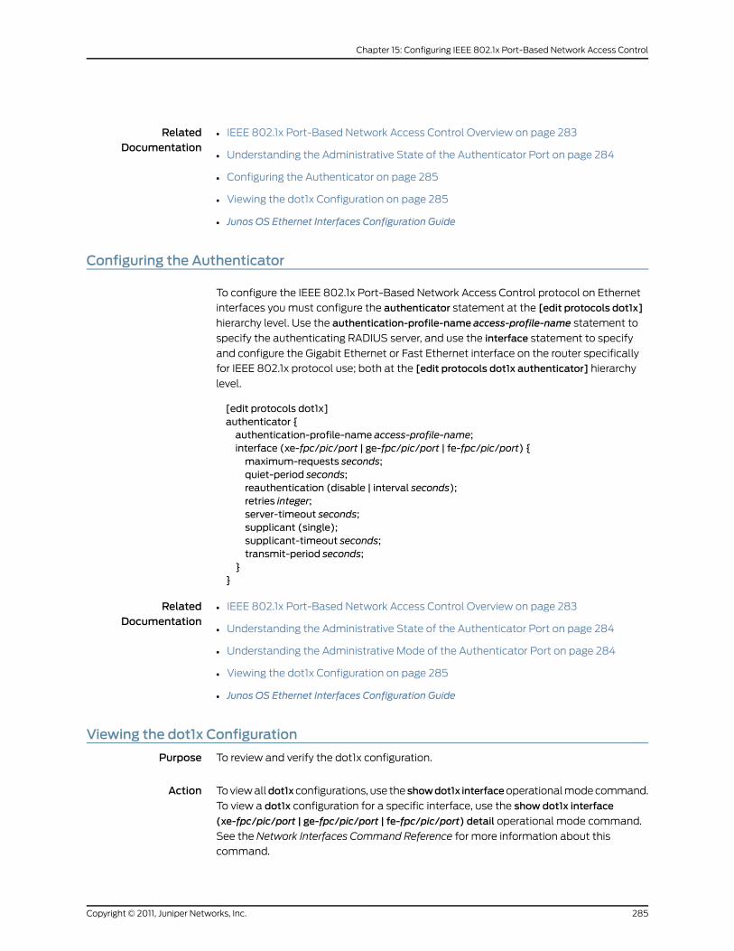
RelatedDocumentation
IEEE 802.1x Port-Based Network Access Control Overview on page 283•
• Understanding the Administrative State of the Authenticator Port on page 284
• Configuring the Authenticator on page 285
• Viewing the dot1x Configuration on page 285
• Junos OS Ethernet Interfaces Configuration Guide
Configuring the Authenticator
To configure the IEEE 802.1x Port-Based Network Access Control protocol on Ethernet
interfaces you must configure the authenticator statement at the [edit protocols dot1x]
hierarchy level. Use the authentication-profile-name access-profile-name statement to
specify the authenticating RADIUS server, and use the interface statement to specify
and configure the Gigabit Ethernet or Fast Ethernet interface on the router specifically
for IEEE 802.1x protocol use; both at the [edit protocols dot1x authenticator] hierarchy
level.
[edit protocols dot1x]authenticator {authentication-profile-name access-profile-name;interface (xe-fpc/pic/port | ge-fpc/pic/port | fe-fpc/pic/port) {maximum-requests seconds;quiet-period seconds;reauthentication (disable | interval seconds);retries integer;server-timeout seconds;supplicant (single);supplicant-timeout seconds;transmit-period seconds;
}}
RelatedDocumentation
IEEE 802.1x Port-Based Network Access Control Overview on page 283•
• Understanding the Administrative State of the Authenticator Port on page 284
• Understanding the Administrative Mode of the Authenticator Port on page 284
• Viewing the dot1x Configuration on page 285
• Junos OS Ethernet Interfaces Configuration Guide
Viewing the dot1x Configuration
Purpose To review and verify the dot1x configuration.
Action To view alldot1xconfigurations, use the showdot1x interfaceoperational mode command.
To view a dot1x configuration for a specific interface, use the show dot1x interface
(xe-fpc/pic/port | ge-fpc/pic/port | fe-fpc/pic/port) detail operational mode command.
See the Network Interfaces Command Reference for more information about this
command.
285Copyright © 2011, Juniper Networks, Inc.
Chapter 15: Configuring IEEE 802.1x Port-Based Network Access Control

RelatedDocumentation
• IEEE 802.1x Port-Based Network Access Control Overview on page 283
• Understanding the Administrative State of the Authenticator Port on page 284
• Understanding the Administrative Mode of the Authenticator Port on page 284
• Configuring the Authenticator on page 285
• Junos OS Ethernet Interfaces Configuration Guide
Copyright © 2011, Juniper Networks, Inc.286
Junos®
OS 11.4 Ethernet Interfaces Configuration Guide

CHAPTER 16
Configuring IEEE802.3ahOAMLink-FaultManagement
• IEEE 802.3ah OAM Link-Fault Management Overview on page 287
• Configuring IEEE 802.3ah OAM Link-Fault Management on page 288
• Enabling IEEE 802.3ah OAM Support on page 290
• Configuring Link Discovery on page 290
• Configuring the OAM PDU Interval on page 291
• Configuring the OAM PDU Threshold on page 292
• Configuring Threshold Values for Local Fault Events on an Interface on page 293
• Disabling the Sending of Link Event TLVs on page 294
• Detecting Remote Faults on page 295
• Configuring an OAM Action Profile on page 296
• Specifying the Actions to Be Taken for Link-Fault Management Events on page 297
• Monitoring the Loss of Link Adjacency on page 298
• Monitoring Protocol Status on page 299
• Configuring Threshold Values for Fault Events in an Action Profile on page 300
• Applying an Action Profile on page 301
• Setting a Remote Interface into Loopback Mode on page 302
• Enabling Remote Loopback Support on the Local Interface on page 303
• Example: Configuring IEEE 802.3ah OAM Support on an Interface on page 304
IEEE 802.3ah OAM Link-Fault Management Overview
Ethernet interfaces capable of running at 100 Mbps or faster on MX Series (except MX
Series routers with MPCs), M Series (except M5 and M10 routers), and T Series routers
support the IEEE 802.3ah standard for Operation, Administration, and Management
(OAM). You can configure IEEE 802.3ah OAM on Ethernet point-to-point direct links or
links across Ethernet repeaters. The IEEE 802.3ah standard meets the requirement for
OAM capabilities as Ethernet moves from being solely an enterprise technology to being
a WAN and access technology, as well as being backward-compatible with existing
Ethernet technology. Junos OS supports IEEE 802.3ah link-fault management.
287Copyright © 2011, Juniper Networks, Inc.

The features of link-fault management are:
• Discovery
• Link monitoring
• Remote fault detection
• Remote loopback
NOTE: Ethernet running on top of a Layer 2 protocol, such as Ethernet overATM, is not supported in OAM configurations.
RelatedDocumentation
Configuring IEEE 802.3ah OAM Link-Fault Management on page 288•
• Enabling IEEE 802.3ah OAM Support on page 290
• Configuring Link Discovery on page 290
• Configuring the OAM PDU Interval on page 291
• Configuring the OAM PDU Threshold on page 292
• Configuring Threshold Values for Local Fault Events on an Interface on page 293
• Disabling the Sending of Link Event TLVs on page 294
• Detecting Remote Faults on page 295
• Configuring an OAM Action Profile on page 296
• Specifying the Actions to Be Taken for Link-Fault Management Events on page 297
• Monitoring the Loss of Link Adjacency on page 298
• Monitoring Protocol Status on page 299
• Configuring Threshold Values for Fault Events in an Action Profile on page 300
• Applying an Action Profile on page 301
• Setting a Remote Interface into Loopback Mode on page 302
• Enabling Remote Loopback Support on the Local Interface on page 303
• Example: Configuring IEEE 802.3ah OAM Support on an Interface on page 304
• Junos OS Ethernet Interfaces Configuration Guide
Configuring IEEE 802.3ah OAM Link-Fault Management
You can configure threshold values for fault events that trigger the sending of link event
TLVs when the values exceed the threshold. To set threshold values for fault events on
an interface, include the event-thresholds statement at the [edit protocols oam ethernet
link-fault-management interface] hierarchy level.
Copyright © 2011, Juniper Networks, Inc.288
Junos®
OS 11.4 Ethernet Interfaces Configuration Guide

You can also configure OAM threshold values within an action profile and apply the action
profile to multiple interfaces. To create an action profile, include the action-profile
statement at the [edit protocols oam ethernet link-fault-management] hierarchy level.
You can configure Ethernet OAM either on an aggregate interface or on each of its member
links. However, we recommend that you configure Ethernet OAM on the aggregate
interface, and this will internally enable Ethernet OAM on the member links.
To view OAM statistics, use the show oam ethernet link-fault-management operational
mode command. To clear OAM statistics, use the clear oam ethernet
link-fault-management statistics operational mode command. To clear link-fault
management state information and restart the link discovery process on Ethernet
interfaces, use the clear oam ethernet link-fault-management state operational mode
command. For more information about these commands, see the Junos OS Interfaces
Command Reference.
RelatedDocumentation
event-thresholds•
• action-profile
• IEEE 802.3ah OAM Link-Fault Management Overview on page 287
• Enabling IEEE 802.3ah OAM Support on page 290
• Configuring Link Discovery on page 290
• Configuring the OAM PDU Interval on page 291
• Configuring the OAM PDU Threshold on page 292
• Configuring Threshold Values for Local Fault Events on an Interface on page 293
• Disabling the Sending of Link Event TLVs on page 294
• Detecting Remote Faults on page 295
• Configuring an OAM Action Profile on page 296
• Specifying the Actions to Be Taken for Link-Fault Management Events on page 297
• Monitoring the Loss of Link Adjacency on page 298
• Monitoring Protocol Status on page 299
• Configuring Threshold Values for Fault Events in an Action Profile on page 300
• Applying an Action Profile on page 301
• Setting a Remote Interface into Loopback Mode on page 302
• Enabling Remote Loopback Support on the Local Interface on page 303
• Example: Configuring IEEE 802.3ah OAM Support on an Interface on page 304
• Junos OS Ethernet Interfaces Configuration Guide
289Copyright © 2011, Juniper Networks, Inc.
Chapter 16: Configuring IEEE 802.3ah OAM Link-Fault Management

Enabling IEEE 802.3ah OAMSupport
To enable IEEE 802.3ah OAM support, include the interface statement at the [edit
protocols oam ethernet link-fault-management] hierarchy level:
[edit protocols oam ethernet link-fault-management interface interface-name]
When you enable IEEE 802.3ah OAM on a physical interface, the discovery process is
automatically triggered.
RelatedDocumentation
link-fault-management on page 467•
• IEEE 802.3ah OAM Link-Fault Management Overview on page 287
• Configuring IEEE 802.3ah OAM Link-Fault Management on page 288
• Configuring Link Discovery on page 290
• Configuring the OAM PDU Interval on page 291
• Configuring the OAM PDU Threshold on page 292
• Configuring Threshold Values for Local Fault Events on an Interface on page 293
• Disabling the Sending of Link Event TLVs on page 294
• Detecting Remote Faults on page 295
• Configuring an OAM Action Profile on page 296
• Specifying the Actions to Be Taken for Link-Fault Management Events on page 297
• Monitoring the Loss of Link Adjacency on page 298
• Monitoring Protocol Status on page 299
• Configuring Threshold Values for Fault Events in an Action Profile on page 300
• Applying an Action Profile on page 301
• Setting a Remote Interface into Loopback Mode on page 302
• Enabling Remote Loopback Support on the Local Interface on page 303
• Example: Configuring IEEE 802.3ah OAM Support on an Interface on page 304
• Junos OS Ethernet Interfaces Configuration Guide
Configuring Link Discovery
When the IEEE 802.3ah OAM protocol is enabled on a physical interface, the discovery
process is automatically triggered. The discovery process permits Ethernet interfaces to
discover and monitor the peer on the link if it also supports the IEEE 802.3ah standard.
You can specify the discovery mode used for IEEE 802.3ah OAM support. The discovery
process is triggered automatically when OAM IEEE 802.3ah functionality is enabled on
a port. Link monitoring is done when the interface sends periodic OAM PDUs.
Copyright © 2011, Juniper Networks, Inc.290
Junos®
OS 11.4 Ethernet Interfaces Configuration Guide
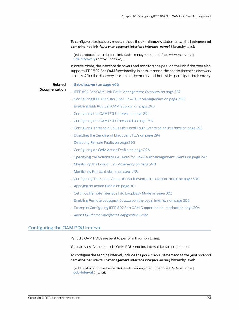
To configure the discovery mode, include the link-discovery statement at the [editprotocol
oam ethernet link-fault-management interface interface-name] hierarchy level:
[edit protocol oam ethernet link-fault-management interface interface-name]link-discovery (active | passive);
In active mode, the interface discovers and monitors the peer on the link if the peer also
supports IEEE 802.3ah OAM functionality. In passive mode, the peer initiates the discovery
process. After the discovery process has been initiated, both sides participate in discovery.
RelatedDocumentation
link-discovery on page 466•
• IEEE 802.3ah OAM Link-Fault Management Overview on page 287
• Configuring IEEE 802.3ah OAM Link-Fault Management on page 288
• Enabling IEEE 802.3ah OAM Support on page 290
• Configuring the OAM PDU Interval on page 291
• Configuring the OAM PDU Threshold on page 292
• Configuring Threshold Values for Local Fault Events on an Interface on page 293
• Disabling the Sending of Link Event TLVs on page 294
• Detecting Remote Faults on page 295
• Configuring an OAM Action Profile on page 296
• Specifying the Actions to Be Taken for Link-Fault Management Events on page 297
• Monitoring the Loss of Link Adjacency on page 298
• Monitoring Protocol Status on page 299
• Configuring Threshold Values for Fault Events in an Action Profile on page 300
• Applying an Action Profile on page 301
• Setting a Remote Interface into Loopback Mode on page 302
• Enabling Remote Loopback Support on the Local Interface on page 303
• Example: Configuring IEEE 802.3ah OAM Support on an Interface on page 304
• Junos OS Ethernet Interfaces Configuration Guide
Configuring the OAMPDU Interval
Periodic OAM PDUs are sent to perform link monitoring.
You can specify the periodic OAM PDU sending interval for fault detection.
To configure the sending interval, include the pdu-interval statement at the [edit protocol
oam ethernet link-fault-management interface interface-name] hierarchy level:
[edit protocol oam ethernet link-fault-management interface interface-name]pdu-interval interval;
291Copyright © 2011, Juniper Networks, Inc.
Chapter 16: Configuring IEEE 802.3ah OAM Link-Fault Management
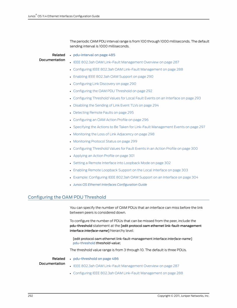
The periodic OAM PDU interval range is from 100 through 1000 milliseconds. The default
sending interval is 1000 milliseconds.
RelatedDocumentation
pdu-interval on page 485•
• IEEE 802.3ah OAM Link-Fault Management Overview on page 287
• Configuring IEEE 802.3ah OAM Link-Fault Management on page 288
• Enabling IEEE 802.3ah OAM Support on page 290
• Configuring Link Discovery on page 290
• Configuring the OAM PDU Threshold on page 292
• Configuring Threshold Values for Local Fault Events on an Interface on page 293
• Disabling the Sending of Link Event TLVs on page 294
• Detecting Remote Faults on page 295
• Configuring an OAM Action Profile on page 296
• Specifying the Actions to Be Taken for Link-Fault Management Events on page 297
• Monitoring the Loss of Link Adjacency on page 298
• Monitoring Protocol Status on page 299
• Configuring Threshold Values for Fault Events in an Action Profile on page 300
• Applying an Action Profile on page 301
• Setting a Remote Interface into Loopback Mode on page 302
• Enabling Remote Loopback Support on the Local Interface on page 303
• Example: Configuring IEEE 802.3ah OAM Support on an Interface on page 304
• Junos OS Ethernet Interfaces Configuration Guide
Configuring the OAMPDU Threshold
You can specify the number of OAM PDUs that an interface can miss before the link
between peers is considered down.
To configure the number of PDUs that can be missed from the peer, include the
pdu-threshold statement at the [edit protocol oam ethernet link-fault-management
interface interface-name] hierarchy level:
[edit protocol oam ethernet link-fault-management interface interface-name]pdu-threshold threshold-value;
The threshold value range is from 3 through 10. The default is three PDUs.
RelatedDocumentation
pdu-threshold on page 486•
• IEEE 802.3ah OAM Link-Fault Management Overview on page 287
• Configuring IEEE 802.3ah OAM Link-Fault Management on page 288
Copyright © 2011, Juniper Networks, Inc.292
Junos®
OS 11.4 Ethernet Interfaces Configuration Guide

• Enabling IEEE 802.3ah OAM Support on page 290
• Configuring Link Discovery on page 290
• Configuring the OAM PDU Interval on page 291
• Configuring Threshold Values for Local Fault Events on an Interface on page 293
• Disabling the Sending of Link Event TLVs on page 294
• Detecting Remote Faults on page 295
• Configuring an OAM Action Profile on page 296
• Specifying the Actions to Be Taken for Link-Fault Management Events on page 297
• Monitoring the Loss of Link Adjacency on page 298
• Monitoring Protocol Status on page 299
• Configuring Threshold Values for Fault Events in an Action Profile on page 300
• Applying an Action Profile on page 301
• Setting a Remote Interface into Loopback Mode on page 302
• Enabling Remote Loopback Support on the Local Interface on page 303
• Example: Configuring IEEE 802.3ah OAM Support on an Interface on page 304
• Junos OS Ethernet Interfaces Configuration Guide
Configuring Threshold Values for Local Fault Events on an Interface
You can configure threshold values on an interface for the local errors that trigger the
sending of link event TLVs.
To set the error threshold values for sending event TLVs, include the frame-error,
frame-period, frame-period-summary, and symbol-periodstatements at the [editprotocols
oamethernet link-fault-management interface interface-nameevent-thresholds]hierarchy
level:
[edit protocol oam ethernet link-fault-management interface interface-name]event-thresholds {frame-error count;frame-period count;frame-period-summary count;symbol-period count;
}
RelatedDocumentation
event-thresholds•
• frame-error
• frame-period
• frame-period-summary
• symbol-period
293Copyright © 2011, Juniper Networks, Inc.
Chapter 16: Configuring IEEE 802.3ah OAM Link-Fault Management

• IEEE 802.3ah OAM Link-Fault Management Overview on page 287
• Configuring IEEE 802.3ah OAM Link-Fault Management on page 288
• Enabling IEEE 802.3ah OAM Support on page 290
• Configuring Link Discovery on page 290
• Configuring the OAM PDU Interval on page 291
• Configuring the OAM PDU Threshold on page 292
• Disabling the Sending of Link Event TLVs on page 294
• Detecting Remote Faults on page 295
• Configuring an OAM Action Profile on page 296
• Specifying the Actions to Be Taken for Link-Fault Management Events on page 297
• Monitoring the Loss of Link Adjacency on page 298
• Monitoring Protocol Status on page 299
• Configuring Threshold Values for Fault Events in an Action Profile on page 300
• Applying an Action Profile on page 301
• Setting a Remote Interface into Loopback Mode on page 302
• Enabling Remote Loopback Support on the Local Interface on page 303
• Example: Configuring IEEE 802.3ah OAM Support on an Interface on page 304
• Junos OS Ethernet Interfaces Configuration Guide
Disabling the Sending of Link Event TLVs
You can disable the sending of link event TLVs.
To disable the monitoring and sending of PDUs containing link event TLVs in periodic
PDUs, include the no-allow-link-events statement at the [edit protocols oam ethernet
link-fault-management interface interface-name negotiation-options] hierarchy level:
[edit protocol oam ethernet link-fault-management interface interface-namenegotiation-options]
no-allow-link-events;
RelatedDocumentation
no-allow-link-events•
• IEEE 802.3ah OAM Link-Fault Management Overview on page 287
• Configuring IEEE 802.3ah OAM Link-Fault Management on page 288
• Enabling IEEE 802.3ah OAM Support on page 290
• Configuring Link Discovery on page 290
• Configuring the OAM PDU Interval on page 291
• Configuring the OAM PDU Threshold on page 292
Copyright © 2011, Juniper Networks, Inc.294
Junos®
OS 11.4 Ethernet Interfaces Configuration Guide

• Configuring Threshold Values for Local Fault Events on an Interface on page 293
• Detecting Remote Faults on page 295
• Configuring an OAM Action Profile on page 296
• Specifying the Actions to Be Taken for Link-Fault Management Events on page 297
• Monitoring the Loss of Link Adjacency on page 298
• Monitoring Protocol Status on page 299
• Configuring Threshold Values for Fault Events in an Action Profile on page 300
• Applying an Action Profile on page 301
• Setting a Remote Interface into Loopback Mode on page 302
• Enabling Remote Loopback Support on the Local Interface on page 303
• Example: Configuring IEEE 802.3ah OAM Support on an Interface on page 304
• Junos OS Ethernet Interfaces Configuration Guide
Detecting Remote Faults
Fault detection is either based on flags or fault event type, length, and values (TLVs)
received in OAM protocol data units (PDUs). Flags that trigger a link fault are:
• Critical Event
• Dying Gasp
• Link Fault
The link event TLVs are sent by the remote DTE by means of event notification PDUs.
Link event TLVs are:
• Errored Symbol Period Event
• Errored Frame Event
• Errored Frame Period Event
• Errored Frame Seconds Summary Event
RelatedDocumentation
IEEE 802.3ah OAM Link-Fault Management Overview on page 287•
• Configuring IEEE 802.3ah OAM Link-Fault Management on page 288
• Enabling IEEE 802.3ah OAM Support on page 290
• Configuring Link Discovery on page 290
• Configuring the OAM PDU Interval on page 291
• Configuring the OAM PDU Threshold on page 292
• Configuring Threshold Values for Local Fault Events on an Interface on page 293
295Copyright © 2011, Juniper Networks, Inc.
Chapter 16: Configuring IEEE 802.3ah OAM Link-Fault Management

• Disabling the Sending of Link Event TLVs on page 294
• Configuring an OAM Action Profile on page 296
• Specifying the Actions to Be Taken for Link-Fault Management Events on page 297
• Monitoring the Loss of Link Adjacency on page 298
• Monitoring Protocol Status on page 299
• Configuring Threshold Values for Fault Events in an Action Profile on page 300
• Applying an Action Profile on page 301
• Setting a Remote Interface into Loopback Mode on page 302
• Enabling Remote Loopback Support on the Local Interface on page 303
• Example: Configuring IEEE 802.3ah OAM Support on an Interface on page 304
• Junos OS Ethernet Interfaces Configuration Guide
Configuring an OAMAction Profile
You can create an action profile to define event fault flags and thresholds and the action
to be taken. You can then apply the action profile to one or more interfaces.
To configure an action profile, include the action-profile statement at the [edit protocols
oam ethernet link-fault-management] hierarchy level:
action-profile profile-name {action {syslog;link-down;send-critical-event;
}event {link-adjacency-loss;link-event-rate {frame-error count;frame-period count;frame-period-summary count;symbol-period count;
}protocol-down;
}}
RelatedDocumentation
action-profile•
• IEEE 802.3ah OAM Link-Fault Management Overview on page 287
• Configuring IEEE 802.3ah OAM Link-Fault Management on page 288
• Enabling IEEE 802.3ah OAM Support on page 290
• Configuring Link Discovery on page 290
Copyright © 2011, Juniper Networks, Inc.296
Junos®
OS 11.4 Ethernet Interfaces Configuration Guide
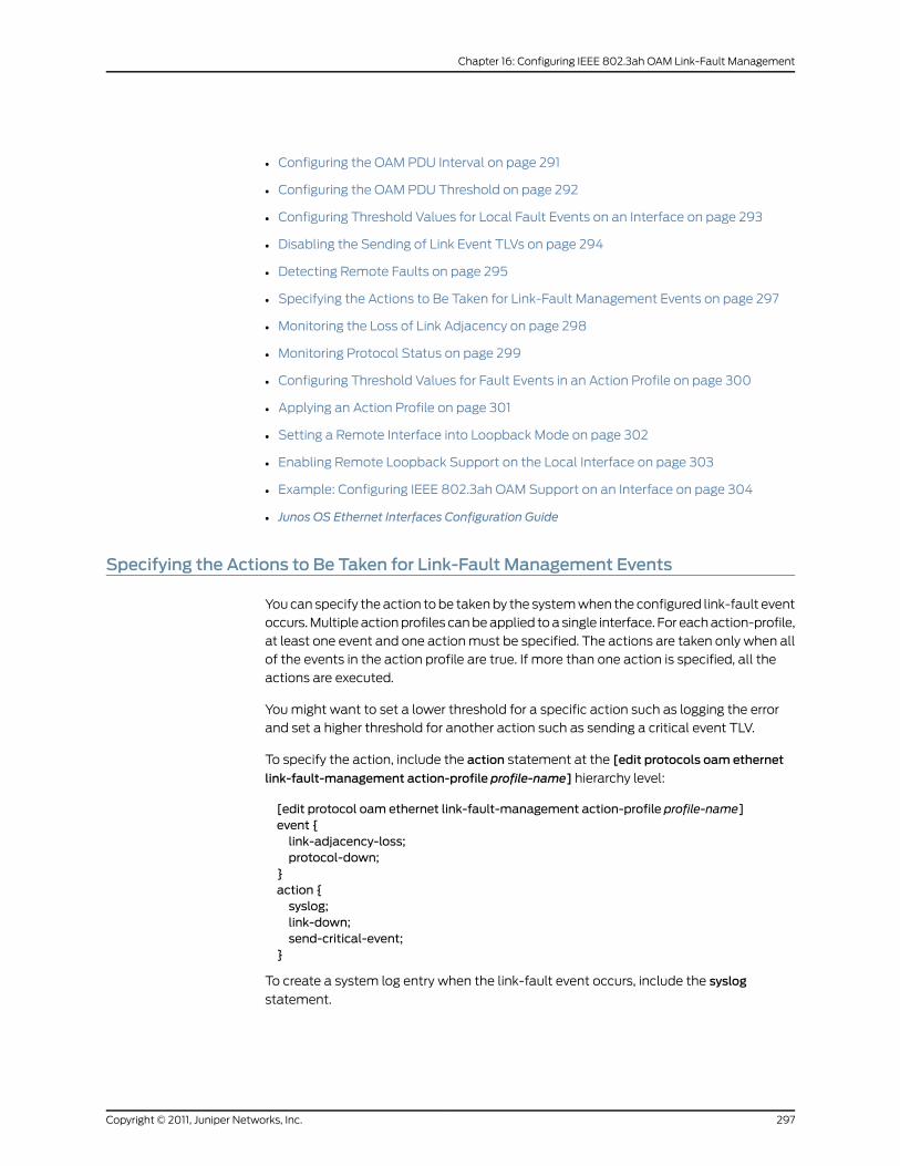
• Configuring the OAM PDU Interval on page 291
• Configuring the OAM PDU Threshold on page 292
• Configuring Threshold Values for Local Fault Events on an Interface on page 293
• Disabling the Sending of Link Event TLVs on page 294
• Detecting Remote Faults on page 295
• Specifying the Actions to Be Taken for Link-Fault Management Events on page 297
• Monitoring the Loss of Link Adjacency on page 298
• Monitoring Protocol Status on page 299
• Configuring Threshold Values for Fault Events in an Action Profile on page 300
• Applying an Action Profile on page 301
• Setting a Remote Interface into Loopback Mode on page 302
• Enabling Remote Loopback Support on the Local Interface on page 303
• Example: Configuring IEEE 802.3ah OAM Support on an Interface on page 304
• Junos OS Ethernet Interfaces Configuration Guide
Specifying the Actions to Be Taken for Link-Fault Management Events
You can specify the action to be taken by the system when the configured link-fault event
occurs. Multiple action profiles can be applied to a single interface. For each action-profile,
at least one event and one action must be specified. The actions are taken only when all
of the events in the action profile are true. If more than one action is specified, all the
actions are executed.
You might want to set a lower threshold for a specific action such as logging the error
and set a higher threshold for another action such as sending a critical event TLV.
To specify the action, include the action statement at the [edit protocols oam ethernet
link-fault-management action-profile profile-name] hierarchy level:
[edit protocol oam ethernet link-fault-management action-profile profile-name]event {link-adjacency-loss;protocol-down;
}action {syslog;link-down;send-critical-event;
}
To create a system log entry when the link-fault event occurs, include the syslog
statement.
297Copyright © 2011, Juniper Networks, Inc.
Chapter 16: Configuring IEEE 802.3ah OAM Link-Fault Management

To administratively disable the link when the link-fault event occurs, include the link-down
statement.
To send IEEE 802.3ah link event TLVs in the OAM PDU when a link-fault event occurs,
include the send-critical-event statement.
NOTE: If multiple actions are specified in the action profile, all of the actionsare executed in no particular order.
RelatedDocumentation
action•
• syslog
• link-down
• send-critical-event
• IEEE 802.3ah OAM Link-Fault Management Overview on page 287
• Configuring IEEE 802.3ah OAM Link-Fault Management on page 288
• Enabling IEEE 802.3ah OAM Support on page 290
• Configuring Link Discovery on page 290
• Configuring the OAM PDU Interval on page 291
• Configuring the OAM PDU Threshold on page 292
• Configuring Threshold Values for Local Fault Events on an Interface on page 293
• Disabling the Sending of Link Event TLVs on page 294
• Detecting Remote Faults on page 295
• Configuring an OAM Action Profile on page 296
• Monitoring the Loss of Link Adjacency on page 298
• Monitoring Protocol Status on page 299
• Configuring Threshold Values for Fault Events in an Action Profile on page 300
• Applying an Action Profile on page 301
• Setting a Remote Interface into Loopback Mode on page 302
• Enabling Remote Loopback Support on the Local Interface on page 303
• Example: Configuring IEEE 802.3ah OAM Support on an Interface on page 304
• Junos OS Ethernet Interfaces Configuration Guide
Monitoring the Loss of Link Adjacency
You can specify actions be taken when link adjacency is lost. When link adjacency is lost,
the system takes the action defined in the action statement of the action profile.
Copyright © 2011, Juniper Networks, Inc.298
Junos®
OS 11.4 Ethernet Interfaces Configuration Guide
To configure the system to take action when link adjacency is lost, include the
link-adjacency-loss statement at the [editprotocolsoamethernet link-fault-management
action-profile profile-name event] hierarchy level:
[edit protocol oam ethernet link-fault-management action-profile profile-name]link-adjacency-loss;
RelatedDocumentation
link-adjacency-loss•
• IEEE 802.3ah OAM Link-Fault Management Overview on page 287
• Configuring IEEE 802.3ah OAM Link-Fault Management on page 288
• Enabling IEEE 802.3ah OAM Support on page 290
• Configuring Link Discovery on page 290
• Configuring the OAM PDU Interval on page 291
• Configuring the OAM PDU Threshold on page 292
• Configuring Threshold Values for Local Fault Events on an Interface on page 293
• Disabling the Sending of Link Event TLVs on page 294
• Detecting Remote Faults on page 295
• Configuring an OAM Action Profile on page 296
• Specifying the Actions to Be Taken for Link-Fault Management Events on page 297
• Monitoring Protocol Status on page 299
• Configuring Threshold Values for Fault Events in an Action Profile on page 300
• Applying an Action Profile on page 301
• Setting a Remote Interface into Loopback Mode on page 302
• Enabling Remote Loopback Support on the Local Interface on page 303
• Example: Configuring IEEE 802.3ah OAM Support on an Interface on page 304
• Junos OS Ethernet Interfaces Configuration Guide
Monitoring Protocol Status
The CCC-DOWN flag is associated with a circuit cross-connect (CCC) connection, Layer
2 circuit, and Layer 2 VPN, which send the CCC-DOWN status to the kernel. The
CCC-DOWN flag indicates that the CCC is down. The CCC-DOWN status is sent to the
kernel when the CCC connection, Layer 2 circuit, or Layer 2 VPN is down. This in turn,
brings down the CE-facing PE router interface associated with the CCC connection, Layer
2 circuit, or Layer 2 VPN.
When the CCC-DOWN flag is signaled to the IEEE 802.3ah protocol, the system takes
the action defined in theaction statement of the action profile. For additional information
about Layer 2 circuits, see the Junos OS Layer 2 Circuits Feature Guide, Junos OS VPNs
Configuration Guide.
299Copyright © 2011, Juniper Networks, Inc.
Chapter 16: Configuring IEEE 802.3ah OAM Link-Fault Management
To monitor the IEEE 802.3ah protocol, on the CE-facing PE router, include the
protocol-down statement at the [edit protocols oam ethernet link-fault-management
action-profile profile-name event] hierarchy level:
[edit protocol oam ethernet link-fault-management action-profile profile-name]protocol-down;
NOTE: If multiple events are specified in the action profile, all the eventsmust occur before the specified action is taken.
RelatedDocumentation
protocol-down on page 501•
• IEEE 802.3ah OAM Link-Fault Management Overview on page 287
• Configuring IEEE 802.3ah OAM Link-Fault Management on page 288
• Enabling IEEE 802.3ah OAM Support on page 290
• Configuring Link Discovery on page 290
• Configuring the OAM PDU Interval on page 291
• Configuring the OAM PDU Threshold on page 292
• Configuring Threshold Values for Local Fault Events on an Interface on page 293
• Disabling the Sending of Link Event TLVs on page 294
• Detecting Remote Faults on page 295
• Configuring an OAM Action Profile on page 296
• Specifying the Actions to Be Taken for Link-Fault Management Events on page 297
• Monitoring the Loss of Link Adjacency on page 298
• Configuring Threshold Values for Fault Events in an Action Profile on page 300
• Applying an Action Profile on page 301
• Setting a Remote Interface into Loopback Mode on page 302
• Enabling Remote Loopback Support on the Local Interface on page 303
• Example: Configuring IEEE 802.3ah OAM Support on an Interface on page 304
• Junos OS Ethernet Interfaces Configuration Guide
Configuring Threshold Values for Fault Events in an Action Profile
You can configure link event thresholds for received error events that trigger the action
specified in the action statement. You can then apply the action profile to one or more
interfaces.
To configure link event thresholds, include the link-event-rate statement at the [edit
protocolsoamethernet link-fault-managementaction-profileprofile-nameevent]hierarchy
level:
Copyright © 2011, Juniper Networks, Inc.300
Junos®
OS 11.4 Ethernet Interfaces Configuration Guide
link-event-rate {frame-error count;frame-period count;frame-period-summary count;symbol-period count;
}
RelatedDocumentation
link-event-rate•
• IEEE 802.3ah OAM Link-Fault Management Overview on page 287
• Configuring IEEE 802.3ah OAM Link-Fault Management on page 288
• Enabling IEEE 802.3ah OAM Support on page 290
• Configuring Link Discovery on page 290
• Configuring the OAM PDU Interval on page 291
• Configuring the OAM PDU Threshold on page 292
• Configuring Threshold Values for Local Fault Events on an Interface on page 293
• Disabling the Sending of Link Event TLVs on page 294
• Detecting Remote Faults on page 295
• Configuring an OAM Action Profile on page 296
• Specifying the Actions to Be Taken for Link-Fault Management Events on page 297
• Monitoring the Loss of Link Adjacency on page 298
• Monitoring Protocol Status on page 299
• Applying an Action Profile on page 301
• Setting a Remote Interface into Loopback Mode on page 302
• Enabling Remote Loopback Support on the Local Interface on page 303
• Example: Configuring IEEE 802.3ah OAM Support on an Interface on page 304
• Junos OS Ethernet Interfaces Configuration Guide
Applying an Action Profile
You can apply an action profile to one or more interfaces.
To apply an action profile to an interface, include the apply-action-profile statement at
the [edit protocols oam ethernet link-fault-management action-profile interface
interface-name] hierarchy level:
[edit protocol oam ethernet link-fault-management interface interface-name]apply-action-profile profile-name;
RelatedDocumentation
apply-action-profile•
• IEEE 802.3ah OAM Link-Fault Management Overview on page 287
301Copyright © 2011, Juniper Networks, Inc.
Chapter 16: Configuring IEEE 802.3ah OAM Link-Fault Management
• Configuring IEEE 802.3ah OAM Link-Fault Management on page 288
• Enabling IEEE 802.3ah OAM Support on page 290
• Configuring Link Discovery on page 290
• Configuring the OAM PDU Interval on page 291
• Configuring the OAM PDU Threshold on page 292
• Configuring Threshold Values for Local Fault Events on an Interface on page 293
• Disabling the Sending of Link Event TLVs on page 294
• Detecting Remote Faults on page 295
• Configuring an OAM Action Profile on page 296
• Specifying the Actions to Be Taken for Link-Fault Management Events on page 297
• Monitoring the Loss of Link Adjacency on page 298
• Monitoring Protocol Status on page 299
• Configuring Threshold Values for Fault Events in an Action Profile on page 300
• Setting a Remote Interface into Loopback Mode on page 302
• Enabling Remote Loopback Support on the Local Interface on page 303
• Example: Configuring IEEE 802.3ah OAM Support on an Interface on page 304
• Junos OS Ethernet Interfaces Configuration Guide
Setting a Remote Interface into LoopbackMode
You can configure the software to set the remote DTE into loopback mode on the
following interfaces:
• IQ2 and IQ2-E Gigabit Ethernet interfaces
• Ethernet interfaces on the MX Series routers
Junos OS can place a remote DTE into loopback mode (if remote-loopback mode is
supported by the remote DTE). When you place a remote DTE into loopback mode, the
interface receives the remote-loopback request and puts the interface into
remote-loopback mode. When the interface is in remote-loopback mode, all frames
except OAM PDUs are looped back without any changes made to the frames. OAM PDUs
continue to be sent to the management plane and processed.
To configure remote loopback, include the remote-loopback statement at the [edit
protocol oam ethernet link-fault-management interface interface-name] hierarchy level:
[edit protocol oam ethernet link-fault-management interface interface-name]remote-loopback;
To take the remote DTE out of loopback mode, remove the remote-loopback statement
from the configuration.
Copyright © 2011, Juniper Networks, Inc.302
Junos®
OS 11.4 Ethernet Interfaces Configuration Guide

RelatedDocumentation
remote-loopback•
• IEEE 802.3ah OAM Link-Fault Management Overview on page 287
• Configuring IEEE 802.3ah OAM Link-Fault Management on page 288
• Enabling IEEE 802.3ah OAM Support on page 290
• Configuring Link Discovery on page 290
• Configuring the OAM PDU Interval on page 291
• Configuring the OAM PDU Threshold on page 292
• Configuring Threshold Values for Local Fault Events on an Interface on page 293
• Disabling the Sending of Link Event TLVs on page 294
• Detecting Remote Faults on page 295
• Configuring an OAM Action Profile on page 296
• Specifying the Actions to Be Taken for Link-Fault Management Events on page 297
• Monitoring the Loss of Link Adjacency on page 298
• Monitoring Protocol Status on page 299
• Configuring Threshold Values for Fault Events in an Action Profile on page 300
• Applying an Action Profile on page 301
• Enabling Remote Loopback Support on the Local Interface on page 303
• Example: Configuring IEEE 802.3ah OAM Support on an Interface on page 304
• Junos OS Ethernet Interfaces Configuration Guide
Enabling Remote Loopback Support on the Local Interface
You can allow a remote DTE to set a local interface into remote loopback mode on IQ2
and IQ2-E Gigabit Ethernet interfaces and all Ethernet interfaces on the MX Series routers.
When a remote-loopback request is sent by a remote DTE, the Junos OS places the local
interface into loopback mode. When an interface is in loopback mode, all frames except
OAM PDUs are looped back without any changes to the frames. OAM PDUs continue to
be sent to the management plane and processed. By default, the remote loopback feature
is not enabled.
To enable remote loopback, include the allow-remote-loopback statement at the [edit
protocoloamethernet link-fault-management interface interface-namenegotiation-options]
hierarchy level:
[edit protocol oam ethernet link-fault-management interface interface-namenegotiation-options]
allow-remote-loopback;
NOTE: Activation of OAM remote loopbackmay result in data frame loss.
303Copyright © 2011, Juniper Networks, Inc.
Chapter 16: Configuring IEEE 802.3ah OAM Link-Fault Management

RelatedDocumentation
allow-remote-loopback•
• IEEE 802.3ah OAM Link-Fault Management Overview on page 287
• Configuring IEEE 802.3ah OAM Link-Fault Management on page 288
• Enabling IEEE 802.3ah OAM Support on page 290
• Configuring Link Discovery on page 290
• Configuring the OAM PDU Interval on page 291
• Configuring the OAM PDU Threshold on page 292
• Configuring Threshold Values for Local Fault Events on an Interface on page 293
• Disabling the Sending of Link Event TLVs on page 294
• Detecting Remote Faults on page 295
• Configuring an OAM Action Profile on page 296
• Specifying the Actions to Be Taken for Link-Fault Management Events on page 297
• Monitoring the Loss of Link Adjacency on page 298
• Monitoring Protocol Status on page 299
• Configuring Threshold Values for Fault Events in an Action Profile on page 300
• Applying an Action Profile on page 301
• Setting a Remote Interface into Loopback Mode on page 302
• Example: Configuring IEEE 802.3ah OAM Support on an Interface on page 304
• Junos OS Ethernet Interfaces Configuration Guide
Example: Configuring IEEE 802.3ah OAMSupport on an Interface
Configure 802.3ah OAM support on an MX Series 10-Gigabit Ethernet interface:
[edit]protocols {oam {ethernet {link-fault-management {interface xe-0/0/0 {link-discovery active;pdu-interval 800;pdu-threshold 4;remote-loopback;negotiation-options {allow-remote-loopback;
}event-thresholds {frame-error 30;frame-period 50;frame-period summary 40;symbol-period 20;
Copyright © 2011, Juniper Networks, Inc.304
Junos®
OS 11.4 Ethernet Interfaces Configuration Guide
}}
}}
}}
RelatedDocumentation
• link-fault-management on page 467
• IEEE 802.3ah OAM Link-Fault Management Overview on page 287
• Configuring IEEE 802.3ah OAM Link-Fault Management on page 288
• Enabling IEEE 802.3ah OAM Support on page 290
• Configuring Link Discovery on page 290
• Configuring the OAM PDU Interval on page 291
• Configuring the OAM PDU Threshold on page 292
• Configuring Threshold Values for Local Fault Events on an Interface on page 293
• Disabling the Sending of Link Event TLVs on page 294
• Detecting Remote Faults on page 295
• Configuring an OAM Action Profile on page 296
• Specifying the Actions to Be Taken for Link-Fault Management Events on page 297
• Monitoring the Loss of Link Adjacency on page 298
• Monitoring Protocol Status on page 299
• Configuring Threshold Values for Fault Events in an Action Profile on page 300
• Applying an Action Profile on page 301
• Setting a Remote Interface into Loopback Mode on page 302
• Enabling Remote Loopback Support on the Local Interface on page 303
• Junos OS Ethernet Interfaces Configuration Guide
305Copyright © 2011, Juniper Networks, Inc.
Chapter 16: Configuring IEEE 802.3ah OAM Link-Fault Management

Copyright © 2011, Juniper Networks, Inc.306
Junos®
OS 11.4 Ethernet Interfaces Configuration Guide

CHAPTER 17
Configuring VRRP and VRRP for IPv6
• VRRP and VRRP for IPv6 Overview on page 307
• Configuring VRRP and VRRP for IPv6 on page 308
VRRP and VRRP for IPv6 Overview
You can configure the Virtual Router Redundancy Protocol (VRRP) and VRRP for IPv6
for the following interfaces:
• Ethernet
• Fast Ethernet
• Tri-Rate Ethernet copper
• Gigabit Ethernet
• 10-Gigabit Ethernet LAN/WAN PIC
• Ethernet logical interfaces
VRRP and VRRP for IPv6 allow hosts on a LAN to make use of redundant routers on that
LAN without requiring more than the static configuration of a single default route on the
hosts. The VRRP routers share the IP address corresponding to the default route
configured on the hosts. At any time, one of the VRRP routers is the master (active) and
the others are backups. If the master fails, one of the backup routers becomes the new
master router, thus always providing a virtual default router and allowing traffic on the
LAN to be routed without relying on a single router.
VRRP is defined in RFC 3768, Virtual Router Redundancy Protocol.
For VRRP and VRRP for IPv6 overview information, configuration guidelines, and
statement summaries, see the Junos OS High Availability Configuration Guide.
RelatedDocumentation
Configuring VRRP and VRRP for IPv6 on page 308•
• Junos OS Ethernet Interfaces Configuration Guide
307Copyright © 2011, Juniper Networks, Inc.

Configuring VRRP and VRRP for IPv6
To configure VRRP or VRRP for IPv6, include the vrrp-groupor vrrp-inet6-group statement,
respectively. These statements are available at the following hierarchy levels:
• [edit interfaces interface-name unit logical-unit-number family inet address address]
• [edit logical-systems logical-system-name interfaces interface-name unit
logical-unit-number family inet address address]
The VRRP and VRRP IPv6 configuration statements are as follows:
(vrrp-group | vrrp-inet-group) group-number {(accept-data | no-accept-data);advertise-interval seconds;authentication-key key;authentication-type authentication;fast-intervalmilliseconds;(preempt | no-preempt) {hold-time seconds;
}priority-number number;track {priority-hold-time;interface interface-name {priority-cost priority;bandwidth-threshold bits-per-second {priority-cost;
}}
}virtual-address [ addresses ];
}
You can configure VRRP IPv6 with a global unicast address.
To trace VRRP and VRRP for IPv6 operations, include the traceoptions statement at the
[edit protocols vrrp] hierarchy level:
[edit protocols vrrp]traceoptions {file <filename> <files number <match regular-expression <microsecond-stamp><size size> <world-readable | no-world-readable>;
flag flag;no-remote-trace;
}
When there are multiple VRRP groups, there is a few seconds delay between the time
the first gratuitous ARP is sent out and the rest of the gratuitous ARP are sent. Configuring
failover-delay compensates for this delay. To configure the failover delay from 500 to
2000 milliseconds for VRRP and VRRP for IPv6 operations, include the failover-delay
milliseconds statement at the [edit protocols vrrp] hierarchy level:
[edit protocols vrrp]failover-delaymilliseconds;
Copyright © 2011, Juniper Networks, Inc.308
Junos®
OS 11.4 Ethernet Interfaces Configuration Guide
To configure the startup period for VRRP and VRRP for IPv6 operations, include the
startup-silent-period statement at the [edit protocols vrrp] hierarchy level:
[edit protocols vrrp]startup-silent-period seconds;
RelatedDocumentation
• VRRP and VRRP for IPv6
• failover-delay
• traceoptions
• failover-delay
• vrrp-group
• VRRP and VRRP for IPv6 Overview on page 307
• Junos OS Ethernet Interfaces Configuration Guide
309Copyright © 2011, Juniper Networks, Inc.
Chapter 17: Configuring VRRP and VRRP for IPv6

Copyright © 2011, Juniper Networks, Inc.310
Junos®
OS 11.4 Ethernet Interfaces Configuration Guide
CHAPTER 18
Configuring Gigabit Ethernet Accountingand Policing
• Gigabit Ethernet Accounting and Policing Overview on page 311
• Configuring Gigabit Ethernet Policers on page 313
• Configuring Gigabit Ethernet Two-Color and Tricolor Policers on page 319
• Configuring MAC Address Accounting on page 322
Gigabit Ethernet Accounting and Policing Overview
For Gigabit Ethernet IQ PICs and Gigabit Ethernet PICs with SFPs (except the 10-port
Gigabit Ethernet PIC and the built-in Gigabit Ethernet port on the M7i router), you can
configure granular per-VLAN class-of-service (CoS) capabilities and extensive
instrumentation and diagnostics on a per-VLAN and per-MAC address basis.
VLAN rewrite, tagging, and deleting enables you to use VLAN address space to support
more customers and services.
VPLS allows you to provide a point-to-multipoint LAN between a set of sites in a VPN.
Ethernet IQ PICs and Gigabit Ethernet PICs with SFPs (except the 10-port Gigabit Ethernet
PIC and the built-in Gigabit Ethernet port on the M7i router) are combined with VPLS to
deliver metro Ethernet service.
For Gigabit Ethernet IQ2 and IQ2-E and 10-Gigabit Ethernet IQ2 and IQ2-E interfaces, you
can apply Layer 2 policing to logical interfaces in the egress or ingress direction. Layer 2
policers are configured at the [edit firewall] hierarchy level. You can also control the rate
of traffic sent or received on an interface by configuring a policer overhead at the [edit
chassis fpc slot-number pic slot-number] hierarchy level.
Table 28 on page 312 lists the capabilities of Gigabit Ethernet IQ PICs and Gigabit Ethernet
PICs with SFPs (except the 10-port Gigabit Ethernet PIC and the built-in Gigabit Ethernet
port on the M7i router).
311Copyright © 2011, Juniper Networks, Inc.

Table 28: Capabilities of Gigabit Ethernet IQ and Gigabit Ethernet withSFPs
GigabitEthernet (SFP)
GigabitEthernet IQ(SFP)Capability
Layer 2
YesYes802.3ad link aggregation
1023384Maximum VLANs per port
91929192Maximum transmission unit (MTU) size
YesYesMAC learning
YesYesMAC accounting
YesYesMAC filtering
960960Destinations per port
6464Sources per port
No, aggregateonly
Yes, premiumand aggregate
Hierarchical MAC policers
YesYesMultiple TPID support and IP service for nonstandardTPIDs
YesYesMultiple Ethernet encapsulations
NoYesDual VLAN tags
NoYesVLAN rewrite
Layer 2 VPNs
YesYesVLAN CCC
YesYesPort-based CCC
YesYesExtended VLAN CCC Virtual Metropolitan Area Network(VMAN) Tag Protocol
CoS
YesYesPIC-based egress queues
NoYesQueued VLANs
YesYesVPLS
Copyright © 2011, Juniper Networks, Inc.312
Junos®
OS 11.4 Ethernet Interfaces Configuration Guide
For more information about configuring VPLS, see the Junos OSVPNs Configuration Guide
and the Junos OS Feature Guides.
You can also configure CoS on logical IQ interfaces. For more information, see the Junos
OS Class of Service Configuration Guide.
RelatedDocumentation
Configuring Gigabit Ethernet Policers on page 313•
• Configuring Gigabit Ethernet Two-Color and Tricolor Policers on page 319
• Configuring MAC Address Accounting on page 322
• Configuring a Policer Overhead
• Junos OS Ethernet Interfaces Configuration Guide
Configuring Gigabit Ethernet Policers
On Gigabit Ethernet IQ and Gigabit Ethernet PICs with SFPs (except the 10-port Gigabit
Ethernet PIC and the built-in Gigabit Ethernet port on the M7i router), you can define rate
limits for premium and aggregate traffic received on the interface. These policers allow
you to perform simple traffic policing without configuring a firewall filter. First you configure
the Ethernet policer profile, next you classify ingress and egress traffic, then you can
apply the policer to a logical interface.
For Gigabit Ethernet PICs with SFPs (except the 10-port Gigabit Ethernet PIC and the
built-in Gigabit Ethernet port on the M7i router), the policer rates you configure can be
different than the rates on the Packet Forward Engine. The difference results from Layer
2 overhead. The PIC accounts for this difference.
NOTE:
OnMXSeries routerswithGigabitEthernetorFastEthernetPICs, the followingconsiderations apply:
• Interface counters do not count the 7-byte preamble and 1-byte framedelimiter in Ethernet frames.
• In MAC statistics, the frame size includesMAC header and CRC before anyVLAN rewrite/imposition rules are applied.
• In traffic statistics, the framesizeencompasses theL2headerwithoutCRCafter any VLAN rewrite/imposition rule.
For information on understanding Ethernet frame statistics, see the MX Series Layer 2
Configuration Guide.
This section contains the following topics:
• Configuring a Policer on page 314
• Specifying an Input Priority Map on page 314
• Specifying an Output Priority Map on page 315
313Copyright © 2011, Juniper Networks, Inc.
Chapter 18: Configuring Gigabit Ethernet Accounting and Policing
• Applying a Policer on page 316
• Configuring MAC Address Filtering on page 317
• Example: Configuring Gigabit Ethernet Policers on page 318
Configuring a Policer
To configure an Ethernet policer profile, include the ethernet-policer-profile statement
at the [edit interfaces interface-name gigether-options ethernet-switch-profile] hierarchy
level:
[edit interfaces interface-name gigether-options ethernet-switch-profile]ethernet-policer-profile {policer cos-policer-name {aggregate {bandwidth-limit bps;burst-size-limit bytes;
}premium {bandwidth-limit bps;burst-size-limit bytes;
}}
}
In the Ethernet policer profile, the aggregate-priority policer is mandatory; the
premium-priority policer is optional.
For aggregate and premium policers, you specify the bandwidth limit in bits per second.
You can specify the value as a complete decimal number or as a decimal number followed
by the abbreviation k (1000),m (1,000,000), or g (1,000,000,000). There is no absolute
minimum value for bandwidth limit, but any value below 61,040 bps will result in an
effective rate of 30,520 bps. The maximum bandwidth limit is 4.29 Gbps.
The maximum burst size controls the amount of traffic bursting allowed. To determine
the burst-size limit, you can multiply the bandwidth of the interface on which you are
applying the filter by the amount of time you allow a burst of traffic at that bandwidth
to occur:
burst size = bandwidth x allowable time for burst traffic
If you do not know the interface bandwidth, you can multiply the maximum MTU of the
traffic on the interface by 10 to obtain a value. For example, the burst size for an MTU of
4700 would be 47,000 bytes. The burst size should be at least 10 interface MTUs. The
maximum value for the burst-size limit is 100 MB.
Specifying an Input Priority Map
An input priority map identifies ingress traffic with specified IEEE 802.1p priority values,
and classifies that traffic as premium.
If you include a premium-priority policer, you can specify an input priority map by including
the ieee802.1 premium statement at the [edit interfaces interface-name gigether-options
ethernet-policer-profile input-priority-map] hierarchy level:
Copyright © 2011, Juniper Networks, Inc.314
Junos®
OS 11.4 Ethernet Interfaces Configuration Guide
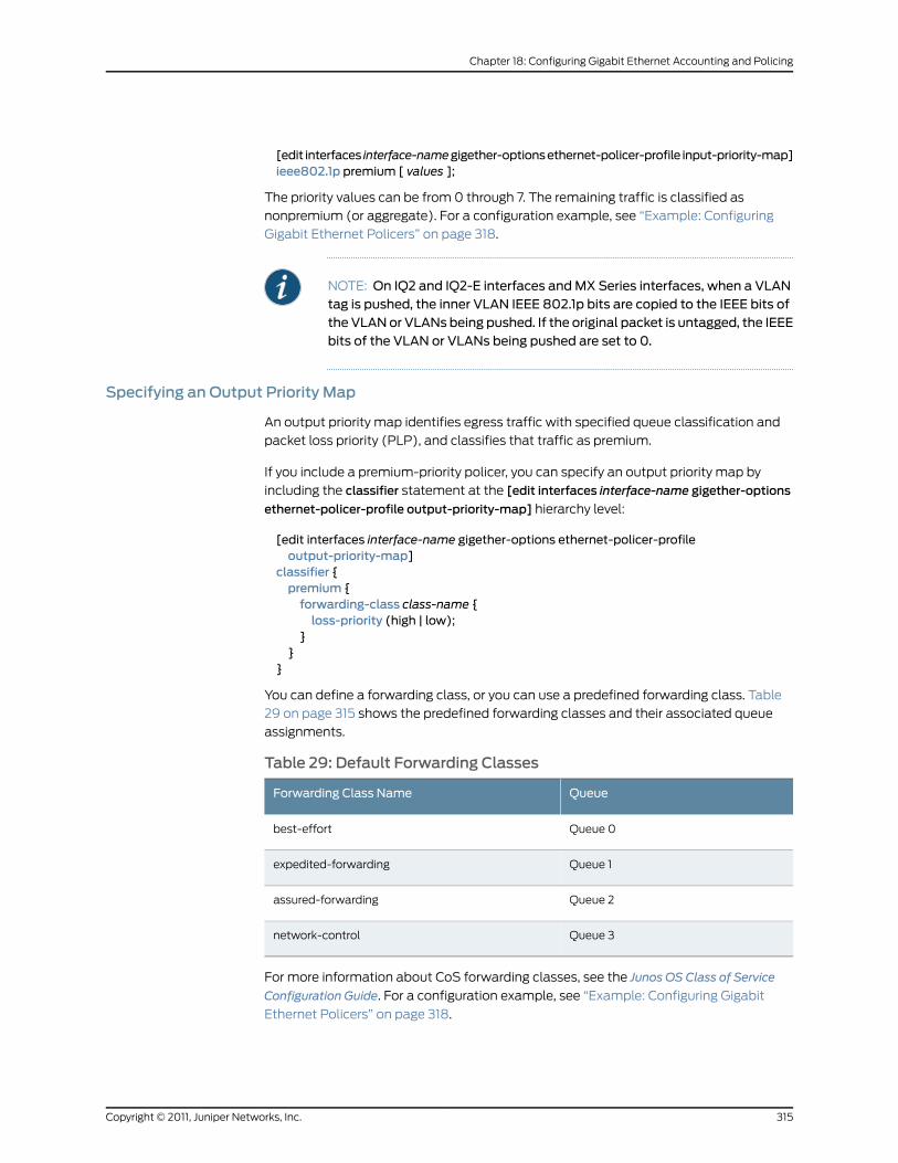
[edit interfaces interface-namegigether-optionsethernet-policer-profile input-priority-map]ieee802.1p premium [ values ];
The priority values can be from 0 through 7. The remaining traffic is classified as
nonpremium (or aggregate). For a configuration example, see “Example: Configuring
Gigabit Ethernet Policers” on page 318.
NOTE: On IQ2 and IQ2-E interfaces andMX Series interfaces, when a VLANtag is pushed, the inner VLAN IEEE 802.1p bits are copied to the IEEE bits ofthe VLANor VLANs being pushed. If the original packet is untagged, the IEEEbits of the VLAN or VLANs being pushed are set to 0.
Specifying an Output Priority Map
An output priority map identifies egress traffic with specified queue classification and
packet loss priority (PLP), and classifies that traffic as premium.
If you include a premium-priority policer, you can specify an output priority map by
including the classifier statement at the [edit interfaces interface-name gigether-options
ethernet-policer-profile output-priority-map] hierarchy level:
[edit interfaces interface-name gigether-options ethernet-policer-profileoutput-priority-map]
classifier {premium {forwarding-class class-name {loss-priority (high | low);
}}
}
You can define a forwarding class, or you can use a predefined forwarding class. Table
29 on page 315 shows the predefined forwarding classes and their associated queue
assignments.
Table 29: Default Forwarding Classes
QueueForwarding Class Name
Queue 0best-effort
Queue 1expedited-forwarding
Queue 2assured-forwarding
Queue 3network-control
For more information about CoS forwarding classes, see the Junos OS Class of Service
Configuration Guide. For a configuration example, see “Example: Configuring Gigabit
Ethernet Policers” on page 318.
315Copyright © 2011, Juniper Networks, Inc.
Chapter 18: Configuring Gigabit Ethernet Accounting and Policing

Applying a Policer
On all MX Series Router interfaces, Gigabit Ethernet IQ, IQ2, and IQ2-E PICs, and Gigabit
Ethernet PICs with SFPs (except the 10-port Gigabit Ethernet PIC and the built-in Gigabit
Ethernet port on the M7i router), you can apply input and output policers that define rate
limits for premium and aggregate traffic received on the logical interface. Aggregate
policers are supported on Gigabit Ethernet PICs with SFPs (except the 10-port Gigabit
Ethernet PIC and the built-in Gigabit Ethernet port on the M7i router).
These policers allow you to perform simple traffic policing without configuring a firewall
filter. For information about defining these policers, see “Configuring Gigabit Ethernet
Policers” on page 313.
To apply policers to specific source MAC addresses, include the accept-source-mac
statement:
accept-source-mac {mac-addressmac-address {policer {input cos-policer-name;output cos-policer-name;
}}
}
You can include these statements at the following hierarchy levels:
• [edit interfaces interface-name unit logical-unit-number ]
• [edit logical-systems logical-system-name interfaces interface-name unit
logical-unit-number]
You can specify the MAC address as nn:nn:nn:nn:nn:nn or nnnn.nnnn.nnnn, where n is a
hexadecimal number. You can configure up to 64 source addresses. To specify more
than one address, include multiple mac-address statements in the logical interface
configuration.
NOTE: On untagged Gigabit Ethernet interfaces you should not configurethe source-address-filter statement at the [edit interfaces ge-fpc/pic/port
gigether-options] hierarchy level and the accept-source-mac statement at
the [edit interfaces ge-fpc/pic/port gigether-options unit logical-unit-number]
hierarchy level simultaneously. If these statements are configured for thesame interfaces at the same time, an error message is displayed.
On tagged Gigabit Ethernet interfaces you should not configure thesource-address-filter statement at the [edit interfaces ge-fpc/pic/port
gigether-options] hierarchy level and the accept-source-mac statement at
the [edit interfaces ge-fpc/pic/port gigether-options unit logical-unit-number]
hierarchy levelwithan identicalMACaddress specified inboth filters. If thesestatements are configured for the same interfaces with an identical MACaddress specified, an error message is displayed.
Copyright © 2011, Juniper Networks, Inc.316
Junos®
OS 11.4 Ethernet Interfaces Configuration Guide

NOTE: If the remote Ethernet card is changed, the interface does not accepttraffic from the newcard because the newcard has a differentMACaddress.
The MAC addresses you include in the configuration are entered into the router’s MAC
database. To view the router’s MAC database, enter the show interfacesmac-database
interface-name command:
user@host> show interfacesmac-database interface-name
In the input statement, list the name of one policer template to be evaluated when
packets are received on the interface.
In the output statement, list the name of one policer template to be evaluated when
packets are transmitted on the interface.
NOTE: On IQ2 and IQ2-E PIC interfaces, the default value for maximumretention of entries in theMACaddress table has changed, for cases inwhichthe table is not full. The new holding time is 12 hours. The previous retentiontime of 3minutes is still in effect when the table is full.
You can use the same policer one or more times.
If you apply both policers and firewall filters to an interface, input policers are evaluated
before input firewall filters, and output policers are evaluated after output firewall filters.
ConfiguringMACAddress Filtering
You cannot explicitly define traffic with specific source MAC addresses to be rejected;
however, for Gigabit Ethernet IQ and Gigabit Ethernet PICs with SFPs (except the 10-port
Gigabit Ethernet PIC and the built-in Gigabit Ethernet port on the M7i router), and for
Gigabit Ethernet DPCs on MX Series routers, you can block all incoming packets that do
not have a source address specified in the accept-source-mac statement. For more
information about theaccept-source-mac statement, see “Applying a Policer” on page 316.
To enable this blocking, include the source-filtering statement at the [edit interfaces
interface-name gigether-options] hierarchy level:
[edit interfaces interface-name gigether-options]source-filtering;
For more information about the source-filtering statement, see “Enabling Ethernet MAC
Address Filtering” on page 42.
To accept traffic even though it does not have a source address specified in the
accept-source-mac statement, include the no-source-filtering statement at the [edit
interfaces interface-name gigether-options] hierarchy level:
[edit interfaces interface-name gigether-options]no-source-filtering;
317Copyright © 2011, Juniper Networks, Inc.
Chapter 18: Configuring Gigabit Ethernet Accounting and Policing
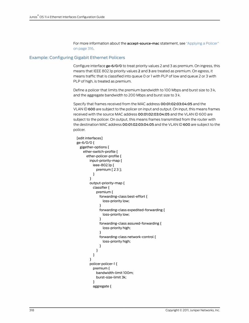
For more information about the accept-source-mac statement, see “Applying a Policer”
on page 316.
Example: Configuring Gigabit Ethernet Policers
Configure interface ge-6/0/0 to treat priority values 2 and 3 as premium. On ingress, this
means that IEEE 802.1p priority values 2 and 3 are treated as premium. On egress, it
means traffic that is classified into queue 0 or 1 with PLP of low and queue 2 or 3 with
PLP of high, is treated as premium.
Define a policer that limits the premium bandwidth to 100 Mbps and burst size to 3 k,
and the aggregate bandwidth to 200 Mbps and burst size to 3 k.
Specify that frames received from the MAC address 00:01:02:03:04:05 and the
VLAN ID 600 are subject to the policer on input and output. On input, this means frames
received with the source MAC address 00:01:02:03:04:05 and the VLAN ID 600 are
subject to the policer. On output, this means frames transmitted from the router with
the destination MAC address00:01:02:03:04:05 and the VLAN ID 600 are subject to the
policer.
[edit interfaces]ge-6/0/0 {gigether-options {ether-switch-profile {ether-policer-profile {input-priority-map {ieee-802.1p {premium [ 2 3 ];
}}output-priority-map {classifier {premium {forwarding-class best-effort {loss-priority low;
}forwarding-class expedited-forwarding {loss-priority low;
}forwarding-class assured-forwarding {loss-priority high;
}forwarding-class network-control {loss-priority high;
}}
}}policer policer-1 {premium {bandwidth-limit 100m;burst-size-limit 3k;
}aggregate {
Copyright © 2011, Juniper Networks, Inc.318
Junos®
OS 11.4 Ethernet Interfaces Configuration Guide
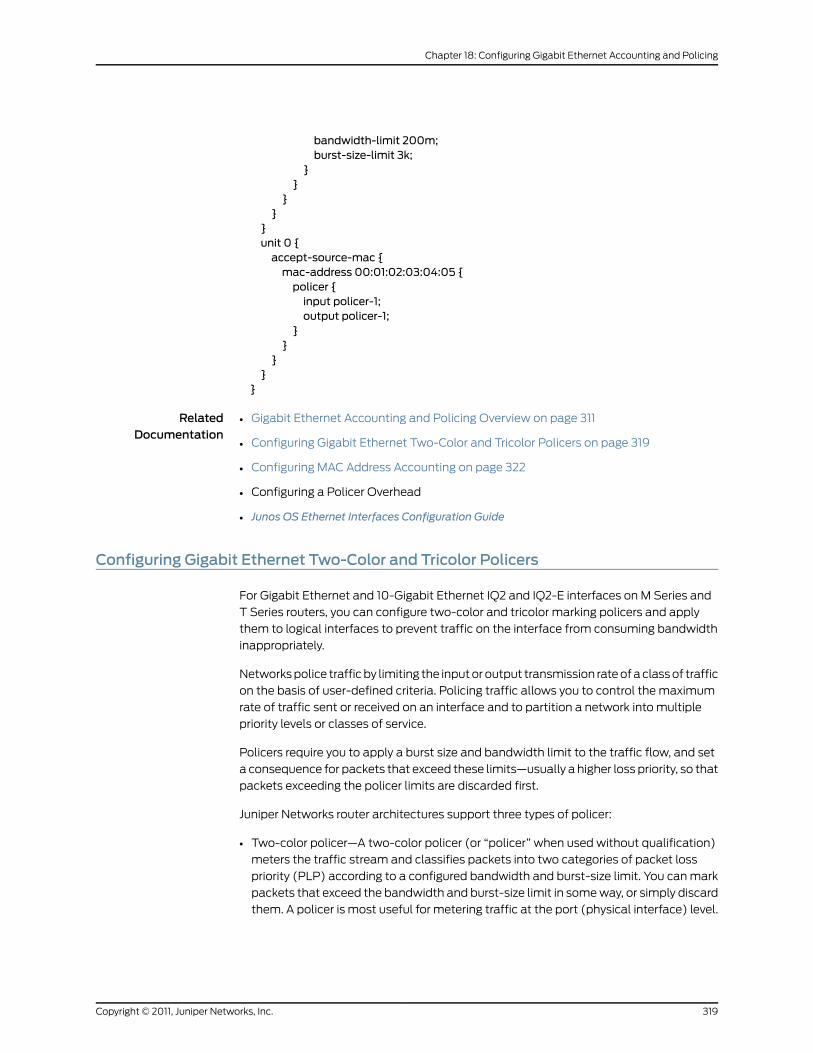
bandwidth-limit 200m;burst-size-limit 3k;
}}
}}
}unit 0 {accept-source-mac {mac-address 00:01:02:03:04:05 {policer {input policer-1;output policer-1;
}}
}}
}
RelatedDocumentation
Gigabit Ethernet Accounting and Policing Overview on page 311•
• Configuring Gigabit Ethernet Two-Color and Tricolor Policers on page 319
• Configuring MAC Address Accounting on page 322
• Configuring a Policer Overhead
• Junos OS Ethernet Interfaces Configuration Guide
Configuring Gigabit Ethernet Two-Color and Tricolor Policers
For Gigabit Ethernet and 10-Gigabit Ethernet IQ2 and IQ2-E interfaces on M Series and
T Series routers, you can configure two-color and tricolor marking policers and apply
them to logical interfaces to prevent traffic on the interface from consuming bandwidth
inappropriately.
Networks police traffic by limiting the input or output transmission rate of a class of traffic
on the basis of user-defined criteria. Policing traffic allows you to control the maximum
rate of traffic sent or received on an interface and to partition a network into multiple
priority levels or classes of service.
Policers require you to apply a burst size and bandwidth limit to the traffic flow, and set
a consequence for packets that exceed these limits—usually a higher loss priority, so that
packets exceeding the policer limits are discarded first.
Juniper Networks router architectures support three types of policer:
• Two-color policer—A two-color policer (or “policer” when used without qualification)
meters the traffic stream and classifies packets into two categories of packet loss
priority (PLP) according to a configured bandwidth and burst-size limit. You can mark
packets that exceed the bandwidth and burst-size limit in some way, or simply discard
them. A policer is most useful for metering traffic at the port (physical interface) level.
319Copyright © 2011, Juniper Networks, Inc.
Chapter 18: Configuring Gigabit Ethernet Accounting and Policing

• Single-rate tricolor marking (srTCM)—A single-rate tricolor marking policer is defined
in RFC 2697, A Single Rate Three Color Marker, as part of an assured forwarding (AF)
per-hop-behavior (PHB) classification system for a Differentiated Services (DiffServ)
environment. This type of policer meters traffic based on the configured committed
information rate (CIR), committed burst size (CBS), and excess burst size (EBS). Traffic
is marked as belonging to one of three categories (green, yellow, or red) based on
whether the packets arriving are below the CBS (green), exceed the CBS (yellow) but
not the EBS, or exceed the EBS (red). Single-rate TCM is most useful when a service
is structured according to packet length and not peak arrival rate.
• Two-rate Tricolor Marking (trTCM)—This type of policer is defined in RFC 2698, A Two
RateThreeColorMarker, as part of an assured forwarding (AF) per-hop-behavior (PHB)
classification system for a Differentiated Services (DiffServ) environment. This type
of policer meters traffic based on the configured CIR and peak information rate (PIR),
along with their associated burst sizes, the CBS and EBS. Traffic is marked as belonging
to one of three categories (green, yellow, or red) based on whether the packets arriving
are below the CIR (green), exceed the CIR (yellow) but not the PIR, or exceed the PIR
(red). Two-rate TCM is most useful when a service is structured according to arrival
rates and not necessarily packet length.
Unlike policing (described in “Configuring Gigabit Ethernet Policers” on page 313),
configuring two-color policers and tricolor marking policers requires that you configure
a firewall filter.
This section contains the following topics:
• Configuring a Policer on page 320
• Applying a Policer on page 321
• Example: Configuring and Applying a Policer on page 321
Configuring a Policer
Two-color and tricolor marking policers are configured at the [edit firewall] hierarchy
level.
A tricolor marking policer polices traffic on the basis of metering rates, including the CIR,
the PIR, their associated burst sizes, and any policing actions configured for the traffic.
To configure tricolor policer marking, include the three-color-policer statement with
options at the [edit firewall] hierarchy level:
[edit firewall]three-color-policer name {action {loss-priority high {then discard;
}}single-rate {(color-aware | color-blind);committed-information-rate bps;committed-burst-size bytes;
Copyright © 2011, Juniper Networks, Inc.320
Junos®
OS 11.4 Ethernet Interfaces Configuration Guide
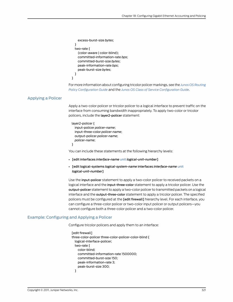
excess-burst-size bytes;}two-rate {(color-aware | color-blind);committed-information-rate bps;committed-burst-size bytes;peak-information-rate bps;peak-burst-size bytes;
}}
For more information about configuring tricolor policer markings, see the JunosOSRouting
Policy Configuration Guide and the Junos OS Class of Service Configuration Guide.
Applying a Policer
Apply a two-color policer or tricolor policer to a logical interface to prevent traffic on the
interface from consuming bandwidth inappropriately. To apply two-color or tricolor
policers, include the layer2-policer statement:
layer2-policer {input-policer policer-name;input-three-color policer-name;output-policer policer-name;policer-name;
}
You can include these statements at the following hierarchy levels:
• [edit interfaces interface-name unit logical-unit-number]
• [edit logical-systems logical-system-name interfaces interface-name unit
logical-unit-number]
Use the input-policer statement to apply a two-color policer to received packets on a
logical interface and the input-three-color statement to apply a tricolor policer. Use the
output-policer statement to apply a two-color policer to transmitted packets on a logical
interface and the output-three-color statement to apply a tricolor policer. The specified
policers must be configured at the [edit firewall] hierarchy level. For each interface, you
can configure a three-color policer or two-color input policer or output policers—you
cannot configure both a three-color policer and a two-color policer.
Example: Configuring and Applying a Policer
Configure tricolor policers and apply them to an interface:
[edit firewall]three-color-policer three-color-policer-color-blind {logical-interface-policer;two-rate {color-blind;committed-information-rate 1500000;committed-burst-size 150;peak-information-rate 3;peak-burst-size 300;
}
321Copyright © 2011, Juniper Networks, Inc.
Chapter 18: Configuring Gigabit Ethernet Accounting and Policing
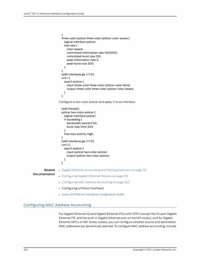
}three-color-policer three-color-policer-color-aware {logical-interface-policer;two-rate {color-aware;committed-information-rate 1500000;committed-burst-size 150;peak-information-rate 3;peak-burst-size 300;
}}[edit interfaces ge-1/1/0]unit 1 {layer2-policer {input-three-color three-color-policer-color-blind;output-three-color three-color-policer-color-aware;
}}
Configure a two-color policer and apply it to an interface:
[edit firewall]policer two-color-policer {logical-interface-policer;if-exceeding {bandwidth-percent 90;burst-size-limit 300;
}then loss-priority-high;
}[edit interfaces ge-1/1/0]unit 2 {layer2-policer {input-policer two-color-policer;output-policer two-color-policer;
}}
RelatedDocumentation
Gigabit Ethernet Accounting and Policing Overview on page 311•
• Configuring Gigabit Ethernet Policers on page 313
• Configuring MAC Address Accounting on page 322
• Configuring a Policer Overhead
• Junos OS Ethernet Interfaces Configuration Guide
ConfiguringMACAddress Accounting
For Gigabit Ethernet IQ and Gigabit Ethernet PICs with SFPs (except the 10-port Gigabit
Ethernet PIC and the built-in Gigabit Ethernet port on the M7i router), and for Gigabit
Ethernet DPCs on MX Series routers, you can configure whether source and destination
MAC addresses are dynamically learned. To configure MAC address accounting, include
Copyright © 2011, Juniper Networks, Inc.322
Junos®
OS 11.4 Ethernet Interfaces Configuration Guide
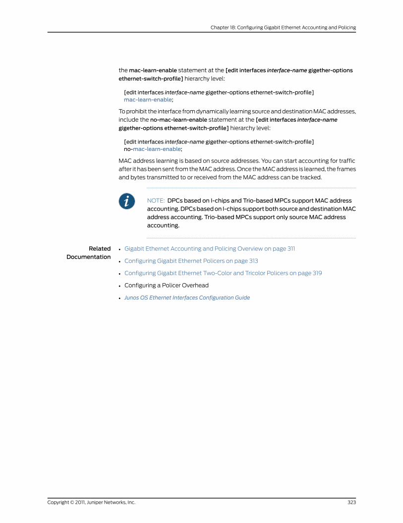
the mac-learn-enable statement at the [edit interfaces interface-name gigether-options
ethernet-switch-profile] hierarchy level:
[edit interfaces interface-name gigether-options ethernet-switch-profile]mac-learn-enable;
To prohibit the interface from dynamically learning source and destination MAC addresses,
include the no-mac-learn-enable statement at the [edit interfaces interface-name
gigether-options ethernet-switch-profile] hierarchy level:
[edit interfaces interface-name gigether-options ethernet-switch-profile]no-mac-learn-enable;
MAC address learning is based on source addresses. You can start accounting for traffic
after it has been sent from the MAC address. Once the MAC address is learned, the frames
and bytes transmitted to or received from the MAC address can be tracked.
NOTE: DPCs based on I-chips and Trio-basedMPCs support MAC addressaccounting.DPCsbasedon I-chipssupportbothsourceanddestinationMACaddress accounting. Trio-basedMPCs support only source MAC addressaccounting.
RelatedDocumentation
• Gigabit Ethernet Accounting and Policing Overview on page 311
• Configuring Gigabit Ethernet Policers on page 313
• Configuring Gigabit Ethernet Two-Color and Tricolor Policers on page 319
• Configuring a Policer Overhead
• Junos OS Ethernet Interfaces Configuration Guide
323Copyright © 2011, Juniper Networks, Inc.
Chapter 18: Configuring Gigabit Ethernet Accounting and Policing

Copyright © 2011, Juniper Networks, Inc.324
Junos®
OS 11.4 Ethernet Interfaces Configuration Guide
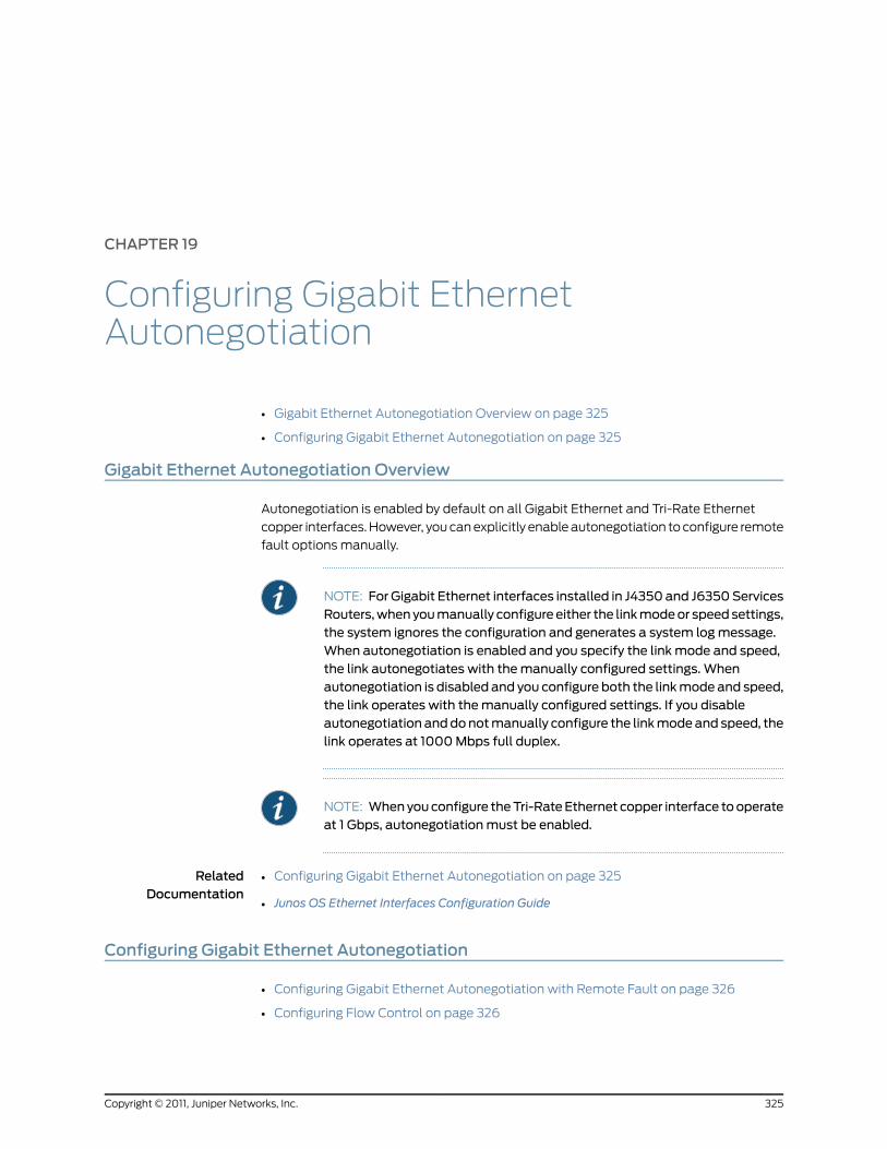
CHAPTER 19
Configuring Gigabit EthernetAutonegotiation
• Gigabit Ethernet Autonegotiation Overview on page 325
• Configuring Gigabit Ethernet Autonegotiation on page 325
Gigabit Ethernet Autonegotiation Overview
Autonegotiation is enabled by default on all Gigabit Ethernet and Tri-Rate Ethernet
copper interfaces. However, you can explicitly enable autonegotiation to configure remote
fault options manually.
NOTE: For Gigabit Ethernet interfaces installed in J4350and J6350ServicesRouters,whenyoumanually configure either the linkmodeor speedsettings,the system ignores the configuration and generates a system logmessage.When autonegotiation is enabled and you specify the link mode and speed,the link autonegotiates with themanually configured settings. Whenautonegotiation is disabled and you configure both the linkmode and speed,the link operates with themanually configured settings. If you disableautonegotiation anddonotmanually configure the linkmodeand speed, thelink operates at 1000Mbps full duplex.
NOTE: Whenyouconfigure theTri-RateEthernet copper interface tooperateat 1 Gbps, autonegotiationmust be enabled.
RelatedDocumentation
Configuring Gigabit Ethernet Autonegotiation on page 325•
• Junos OS Ethernet Interfaces Configuration Guide
Configuring Gigabit Ethernet Autonegotiation
• Configuring Gigabit Ethernet Autonegotiation with Remote Fault on page 326
• Configuring Flow Control on page 326
325Copyright © 2011, Juniper Networks, Inc.
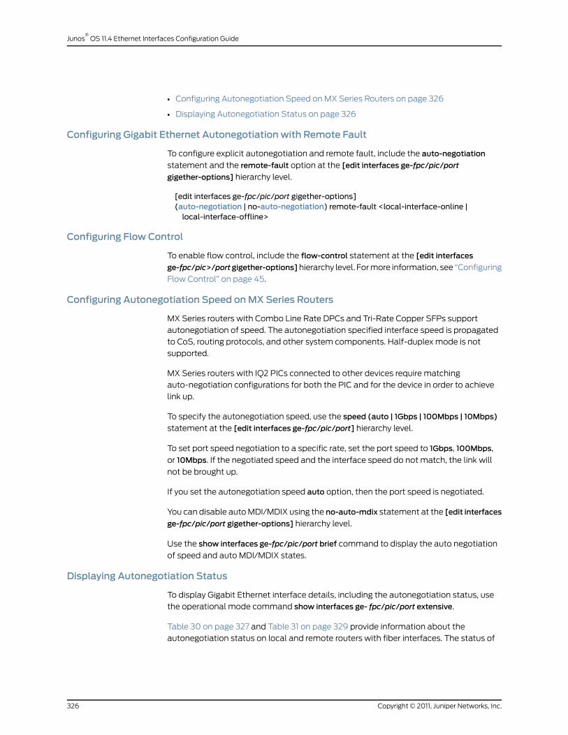
• Configuring Autonegotiation Speed on MX Series Routers on page 326
• Displaying Autonegotiation Status on page 326
Configuring Gigabit Ethernet Autonegotiation with Remote Fault
To configure explicit autonegotiation and remote fault, include the auto-negotiation
statement and the remote-fault option at the [edit interfaces ge-fpc/pic/port
gigether-options] hierarchy level.
[edit interfaces ge-fpc/pic/port gigether-options](auto-negotiation | no-auto-negotiation) remote-fault <local-interface-online |local-interface-offline>
Configuring Flow Control
To enable flow control, include the flow-control statement at the [edit interfaces
ge-fpc/pic>/portgigether-options]hierarchy level. For more information, see “Configuring
Flow Control” on page 45.
Configuring Autonegotiation Speed onMX Series Routers
MX Series routers with Combo Line Rate DPCs and Tri-Rate Copper SFPs support
autonegotiation of speed. The autonegotiation specified interface speed is propagated
to CoS, routing protocols, and other system components. Half-duplex mode is not
supported.
MX Series routers with IQ2 PICs connected to other devices require matching
auto-negotiation configurations for both the PIC and for the device in order to achieve
link up.
To specify the autonegotiation speed, use the speed (auto | 1Gbps | 100Mbps | 10Mbps)
statement at the [edit interfaces ge-fpc/pic/port] hierarchy level.
To set port speed negotiation to a specific rate, set the port speed to 1Gbps, 100Mbps,
or 10Mbps. If the negotiated speed and the interface speed do not match, the link will
not be brought up.
If you set the autonegotiation speed auto option, then the port speed is negotiated.
You can disable auto MDI/MDIX using the no-auto-mdix statement at the [edit interfaces
ge-fpc/pic/port gigether-options] hierarchy level.
Use the show interfaces ge-fpc/pic/port brief command to display the auto negotiation
of speed and auto MDI/MDIX states.
Displaying Autonegotiation Status
To display Gigabit Ethernet interface details, including the autonegotiation status, use
the operational mode command show interfaces ge- fpc/pic/port extensive.
Table 30 on page 327 and Table 31 on page 329 provide information about the
autonegotiation status on local and remote routers with fiber interfaces. The status of
Copyright © 2011, Juniper Networks, Inc.326
Junos®
OS 11.4 Ethernet Interfaces Configuration Guide
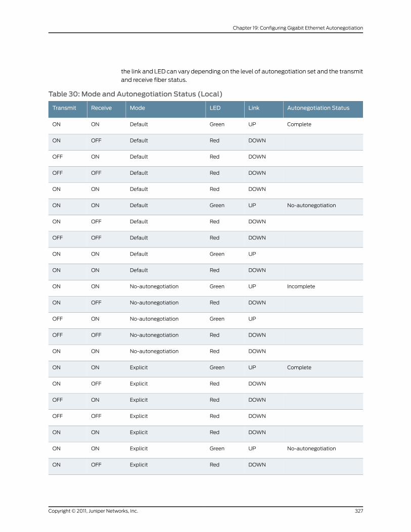
the link and LED can vary depending on the level of autonegotiation set and the transmit
and receive fiber status.
Table 30: Mode and Autonegotiation Status (Local)
Autonegotiation StatusLinkLEDModeReceiveTransmit
CompleteUPGreenDefaultONON
DOWNRedDefaultOFFON
DOWNRedDefaultONOFF
DOWNRedDefaultOFFOFF
DOWNRedDefaultONON
No-autonegotiationUPGreenDefaultONON
DOWNRedDefaultOFFON
DOWNRedDefaultOFFOFF
UPGreenDefaultONON
DOWNRedDefaultONON
IncompleteUPGreenNo-autonegotiationONON
DOWNRedNo-autonegotiationOFFON
UPGreenNo-autonegotiationONOFF
DOWNRedNo-autonegotiationOFFOFF
DOWNRedNo-autonegotiationONON
CompleteUPGreenExplicitONON
DOWNRedExplicitOFFON
DOWNRedExplicitONOFF
DOWNRedExplicitOFFOFF
DOWNRedExplicitONON
No-autonegotiationUPGreenExplicitONON
DOWNRedExplicitOFFON
327Copyright © 2011, Juniper Networks, Inc.
Chapter 19: Configuring Gigabit Ethernet Autonegotiation

Table 30: Mode and Autonegotiation Status (Local) (continued)
Autonegotiation StatusLinkLEDModeReceiveTransmit
UPGreenExplicitONOFF
DOWNRedExplicitOFFOFF
DOWNRedExplicitONON
CompleteUPGreenExplicit+RFI-OfflineONON
DOWNRedExplicit+RFI-OfflineONOFF
DOWNRedExplicit+RFI-OfflineOFFOFF
DOWNRedExplicit+RFI-OfflineONON
No-autonegotiationUPGreenExplicit+RFI-OfflineONON
DOWNRedExplicit+RFI-OfflineOFFON
UPGreenExplicit+RFI-OfflineONOFF
DOWNRedExplicit+RFI-OfflineOFFOFF
DOWNRedExplicit+RFI-OfflineONON
CompleteDOWNRedExplicit+RFI-OfflineONON
DOWNRedExplicit+RFI-OfflineOFFON
DOWNRedExplicit+RFI-OnlineONOFF
DOWNRedExplicit+RFI-OnlineOFFOFF
DOWNRedExplicit+RFI-OnlineONON
No-autonegotiation*UPGreenExplicit+RFI-OnlineONON
DOWNRedExplicit+RFI-OnlineOFFON
UPGreenExplicit+RFI-OnlineONOFF
DOWNRedExplicit+RFI-OnlineOFFOFF
UPGreenExplicit+RFI-OnlineONON
DOWNRedExplicit+RFI-OnlineONON
CompleteDOWNRedExplicit+RFI-OnlineONON
Copyright © 2011, Juniper Networks, Inc.328
Junos®
OS 11.4 Ethernet Interfaces Configuration Guide
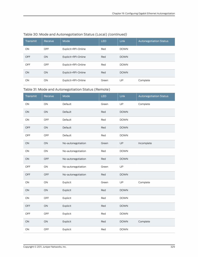
Table 30: Mode and Autonegotiation Status (Local) (continued)
Autonegotiation StatusLinkLEDModeReceiveTransmit
DOWNRedExplicit+RFI-OnlineOFFON
DOWNRedExplicit+RFI-OnlineONOFF
DOWNRedExplicit+RFI-OnlineOFFOFF
DOWNRedExplicit+RFI-OnlineONON
CompleteUPGreenExplicit+RFI-OnlineONON
Table 31: Mode and Autonegotiation Status (Remote)
Autonegotiation StatusLinkLEDModeReceiveTransmit
CompleteUPGreenDefaultONON
DOWNRedDefaultONON
DOWNRedDefaultOFFON
DOWNRedDefaultONOFF
DOWNRedDefaultOFFOFF
IncompleteUPGreenNo-autonegotiationONON
DOWNRedNo-autonegotiationONON
DOWNRedNo-autonegotiationOFFON
UPGreenNo-autonegotiationONOFF
DOWNRedNo-autonegotiationOFFOFF
CompleteUPGreenExplicitONON
DOWNRedExplicitONON
DOWNRedExplicitOFFON
DOWNRedExplicitONOFF
DOWNRedExplicitOFFOFF
CompleteDOWNRedExplicitONON
DOWNRedExplicitOFFON
329Copyright © 2011, Juniper Networks, Inc.
Chapter 19: Configuring Gigabit Ethernet Autonegotiation
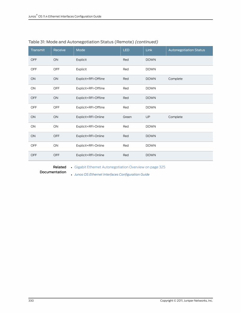
Table 31: Mode and Autonegotiation Status (Remote) (continued)
Autonegotiation StatusLinkLEDModeReceiveTransmit
DOWNRedExplicitONOFF
DOWNRedExplicitOFFOFF
CompleteDOWNRedExplicit+RFI-OfflineONON
DOWNRedExplicit+RFI-OfflineOFFON
DOWNRedExplicit+RFI-OfflineONOFF
DOWNRedExplicit+RFI-OfflineOFFOFF
CompleteUPGreenExplicit+RFI-OnlineONON
DOWNRedExplicit+RFI-OnlineONON
DOWNRedExplicit+RFI-OnlineOFFON
DOWNRedExplicit+RFI-OnlineONOFF
DOWNRedExplicit+RFI-OnlineOFFOFF
RelatedDocumentation
• Gigabit Ethernet Autonegotiation Overview on page 325
• Junos OS Ethernet Interfaces Configuration Guide
Copyright © 2011, Juniper Networks, Inc.330
Junos®
OS 11.4 Ethernet Interfaces Configuration Guide
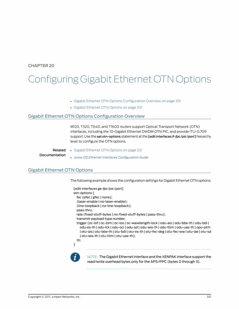
CHAPTER 20
ConfiguringGigabit EthernetOTNOptions
• Gigabit Ethernet OTN Options Configuration Overview on page 331
• Gigabit Ethernet OTN Options on page 331
Gigabit Ethernet OTNOptions Configuration Overview
M120, T320, T640, and T1600 routers support Optical Transport Network (OTN)
interfaces, including the 10-Gigabit Ethernet DWDM OTN PIC, and provide ITU-G.709
support. Use the setotn-options statement at the [edit interfaces if-fpc/pic/port]hierarchy
level to configure the OTN options.
RelatedDocumentation
Gigabit Ethernet OTN Options on page 331•
• Junos OS Ethernet Interfaces Configuration Guide
Gigabit Ethernet OTNOptions
The following example shows the configuration settings for Gigabit Ethernet OTN options:
[edit interfaces ge-fpc/pic/port]otn-options {fec (efec | gfec | none);(laser-enable | no-laser-enable);(line-loopback | no-line-loopback);pass-thru;rate (fixed-stuff-bytes | no-fixed-stuff-bytes | pass-thru);transmit-payload-type number;trigger (oc-lof | oc-lom | oc-los | oc-wavelength-lock | odu-ais | odu-bbe-th | odu-bdi |odu-es-th | odu-lck | odu-oci | odu-sd | odu-ses-th | odu-ttim | odu-uas-th | opu-ptm| otu-ais | otu-bbe-th | otu-bdi | otu-es-th | otu-fec-deg | otu-fec-exe | otu-iae | otu-sd| otu-ses-th | otu-ttim | otu-uas-th);
tti;}
NOTE: TheGigabit Ethernet interface and theXENPAK interface support theread/write overhead bytes only for the APS/PPC (bytes 0 through 3).
331Copyright © 2011, Juniper Networks, Inc.

You can use the following show commands to view the OTN configuration:
• showinterfacesextensive—See the JunosOSInterfacesCommandReference for command
details.
• showchassishardware—See the JunosOSSystemBasicsandServicesCommandReference
for command details.
• show chassis pic—See the Junos OS System Basics and Services Command Reference for
command details.
RelatedDocumentation
• Gigabit Ethernet OTN Options Configuration Overview on page 331
• Junos OS Ethernet Interfaces Configuration Guide
Copyright © 2011, Juniper Networks, Inc.332
Junos®
OS 11.4 Ethernet Interfaces Configuration Guide

CHAPTER 21
Configuring the Management EthernetInterface
• Management Ethernet Interface Overview on page 333
• Configuring a Consistent Management IP Address on page 334
• Configuring the MAC Address on the Management Ethernet Interface on page 335
Management Ethernet Interface Overview
The router’s management Ethernet interface, fxp0orem0, is an out-of-band management
interface that needs to be configured only if you want to connect to the router through
the management port on the front of the router. You can configure an IP address and
prefix length for this interface, which you commonly do when you first install the Junos
OS:
[edit]user@host# set interfaces (fxp0 | em0) unit 0 family inet address/prefix-length[edit]user@host# showinterfaces {(fxp0 | em0) {unit 0 {family inet {address/prefix-length;
}}
}}
RelatedDocumentation
Configuring a Consistent Management IP Address on page 334•
• Configuring the MAC Address on the Management Ethernet Interface on page 335
• Junos OS Ethernet Interfaces Configuration Guide
333Copyright © 2011, Juniper Networks, Inc.

Configuring a Consistent Management IP Address
On routers with multiple Routing Engines, each Routing Engine is configured with a
separate IP address for the management Ethernet interface. To access the master Routing
Engine, you must know which Routing Engine is active and use the appropriate IP address.
Optionally, for consistent access to the master Routing Engine, you can configure an
additional IP address and use this address for the management interface regardless of
which Routing Engine is active. This additional IP address is active only on the
management Ethernet interface for the master Routing Engine. During switchover, the
address moves to the new master Routing Engine.
NOTE: For M Series, MX Series, andmost T Series routers, themanagementEthernet interface is fxp0. For TXMatrix Plus routers and T1600 routers
configured in a routingmatrix, themanagement Ethernet interface is em0.
NOTE: Automated scripts that you have developed for standalone T1600routers (T1600 routers that are not in a routingmatrix) might containreferences to the fxp0management Ethernet interface. Before reusing the
scripts on T1600 routers in a routingmatrix, edit the command lines thatreference the fxp0management Ethernet interface so that the commands
reference the em0management Ethernet interface instead.
To configure an additional IP address for the management Ethernet interface, include
the master-only statement at the [edit groups] hierarchy level.
In the following example, IP address 10.17.40.131 is configured for both Routing Engines
and includes a master-only statement. With this configuration, the 10.17.40.131 address
is active only on the master Routing Engine. The address remains consistent regardless
of which Routing Engine is active. IP address 10.17.40.132 is assigned to fxp0 on re0, and
address 10.17.40.133 is assigned to fxp0 on re1.
[edit groups re0 interfaces fxp0]unit 0 {family inet {address 10.17.40.131/25 {master-only;
}address 10.17.40.132/25;
}}[edit groups re1 interfaces fxp0]unit 0 {family inet {address 10.17.40.131/25 {master-only;
}address 10.17.40.133/25;
Copyright © 2011, Juniper Networks, Inc.334
Junos®
OS 11.4 Ethernet Interfaces Configuration Guide

}}
This feature is available on all routers that include dual Routing Engines. On the TX Matrix
router, this feature is applicable to the switch-card chassis (SCC) only.
RelatedDocumentation
Management Ethernet Interface Overview on page 333•
• Configuring the MAC Address on the Management Ethernet Interface on page 335
• Junos OS Ethernet Interfaces Configuration Guide
Configuring theMACAddress on theManagement Ethernet Interface
By default, the router’s management Ethernet interface uses as its MAC address the MAC
address that is burned into the Ethernet card.
NOTE: For M Series, MX Series, andmost T Series routers, themanagementEthernet interface is fxp0. For TXMatrix Plus routers and T1600 routers
configured in a routingmatrix, themanagement Ethernet interface is em0.
NOTE: Automated scripts that you have developed for standalone T1600routers (T1600 routers that are not in a routingmatrix) might containreferences to the fxp0management Ethernet interface. Before reusing the
scripts on T1600 routers in a routingmatrix, edit the command lines thatreference the fxp0management Ethernet interface so that the commands
reference the em0management Ethernet interface instead.
To display the MAC address used by the router’s management Ethernet interface, enter
the show interface fxp0 or show interface em0 operational mode command.
To change the management Ethernet interface’s MAC address, include themac statement
at the [edit interfaces fxp0] or [edit interfaces em0] hierarchy level:
[edit interfaces (fxp0 | em0)]macmac-address;
Specify the MAC address as six hexadecimal bytes in one of the following formats:
nnnn.nnnn.nnnn (for example, 0011.2233.4455) or nn:nn:nn:nn:nn:nn (for example,
00:11:22:33:44:55).
335Copyright © 2011, Juniper Networks, Inc.
Chapter 21: Configuring the Management Ethernet Interface

NOTE: If you integrate a standalone T640 router into a routingmatrix, thePIC MAC addresses for the integrated T640 router are derived from a poolofMACaddressesmaintainedby theTXMatrix router. For eachMACaddressyou specify in the configuration of a formerly standalone T640 router, youmust specify the sameMAC address in the configuration of the TXMatrixrouter.
Similarly, if you integrate a standalone T1600 router into a routingmatrix,the PIC MAC addresses for the integrated T1600 router are derived from apool of MAC addressesmaintained by the TXMatrix Plus router. For eachMACaddressyouspecify in theconfigurationofa formerly standaloneT1600router, youmust specify the sameMAC address in the configuration of theTXMatrix Plus router.
RelatedDocumentation
• Management Ethernet Interface Overview on page 333
• Configuring a Consistent Management IP Address on page 334
• Junos OS Ethernet Interfaces Configuration Guide
Copyright © 2011, Juniper Networks, Inc.336
Junos®
OS 11.4 Ethernet Interfaces Configuration Guide
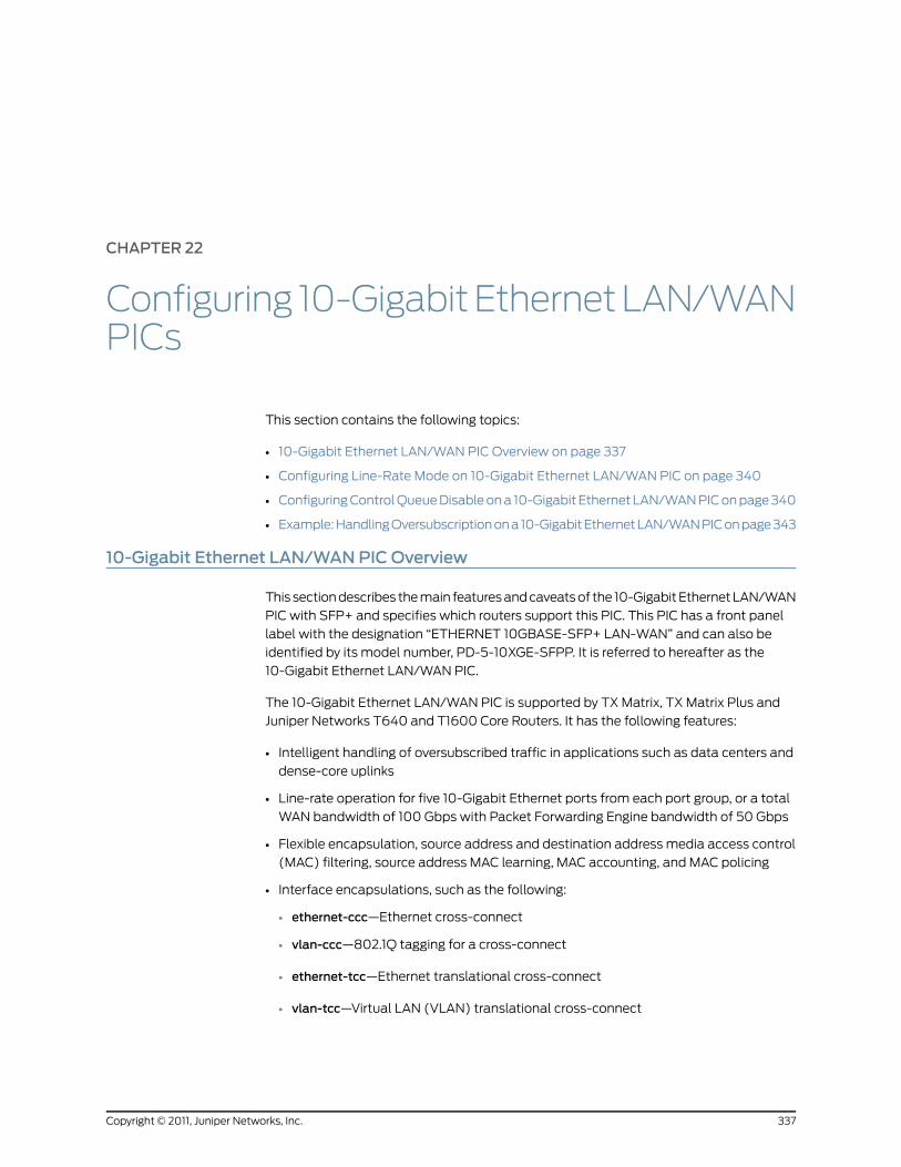
CHAPTER 22
Configuring 10-GigabitEthernetLAN/WANPICs
This section contains the following topics:
• 10-Gigabit Ethernet LAN/WAN PIC Overview on page 337
• Configuring Line-Rate Mode on 10-Gigabit Ethernet LAN/WAN PIC on page 340
• Configuring Control Queue Disable on a 10-Gigabit Ethernet LAN/WAN PIC on page 340
• Example: Handling Oversubscription on a 10-Gigabit Ethernet LAN/WAN PIC on page 343
10-Gigabit Ethernet LAN/WANPIC Overview
This section describes the main features and caveats of the 10-Gigabit Ethernet LAN/WAN
PIC with SFP+ and specifies which routers support this PIC. This PIC has a front panel
label with the designation “ETHERNET 10GBASE-SFP+ LAN-WAN” and can also be
identified by its model number, PD-5-10XGE-SFPP. It is referred to hereafter as the
10-Gigabit Ethernet LAN/WAN PIC.
The 10-Gigabit Ethernet LAN/WAN PIC is supported by TX Matrix, TX Matrix Plus and
Juniper Networks T640 and T1600 Core Routers. It has the following features:
• Intelligent handling of oversubscribed traffic in applications such as data centers and
dense-core uplinks
• Line-rate operation for five 10-Gigabit Ethernet ports from each port group, or a total
WAN bandwidth of 100 Gbps with Packet Forwarding Engine bandwidth of 50 Gbps
• Flexible encapsulation, source address and destination address media access control
(MAC) filtering, source address MAC learning, MAC accounting, and MAC policing
• Interface encapsulations, such as the following:
• ethernet-ccc—Ethernet cross-connect
• vlan-ccc—802.1Q tagging for a cross-connect
• ethernet-tcc—Ethernet translational cross-connect
• vlan-tcc—Virtual LAN (VLAN) translational cross-connect
337Copyright © 2011, Juniper Networks, Inc.

• extended-vlan-ccc—Standard Tag Protocol Identifier (TPID) tagging for a
cross-connect
• ethernet-vpls—Ethernet virtual private LAN service
• vlan-vpls—VLAN virtual private LAN service
• flexible-ethernet-services—Allows per-unit Ethernet encapsulation configuration
• Single, stacked, and flexible VLAN tagging modes
• Native VLAN configuration to allow untagged frames to be received on the tagged
interfaces
• Maximum transmission unit (MTU) size of up to 9192 bytes for Ethernet frames
• Link aggregation group (LAG) on single chassis
• Interoperability with other 10-Gigabit Ethernet PICs in M Series and T Series routers in
the LAN PHY and WAN PHY modes
• Interrupt-driven link-down detection mechanism
• Two-to-one oversubscription of traffic across a port group
Traffic from 10 ingress ports to the Packet Forwarding Engine traffic is statically mapped
to one of the 5 egress ports. 10 Gbps of bandwidth toward the Packet Forwarding
Engine is shared by two ingress ports (called aport group), thereby achieving two-to-one
oversubscription. This scheme provides two-to-one oversubscription across a port
group and not across the entire PIC.
• Four queues per physical interface on ingress and eight queues per physical interface
on egress
• A separate control queue per physical interface to ensure that the control packets are
not dropped during oversubscribed traffic. The control queue can be disabled in the
CLI.
• SFP+ optical diagnostics
SFP+ is a next-generation transceiver module form factor specified by the ANSI T11
Group for 8.5-Gbps and 10-Gbps fiber channel and Ethernet applications. The SFP+
form factor is 30 percent smaller than the XFP form factor. The benefits include higher
port density, lower power modules, and lower system costs. The 10-Gigabit Ethernet
LAN/WAN PIC supports 10GBASE-SR and 10GBASE-LR SFP+ optics.
• Behavior aggregate (BA) classification (IPv4 DSCP, IPv6 DSCP, Inet precedence, IEEE
802.1P, IEEE 802.1AD, MPLS EXP) and fixed classification
• Weighted round-robin scheduling with two queue priorities (low and strict-high)
• Committed information rate and peak information rate shaping on a per-queue basis
• Excess information rate configuration for allocation of excess bandwidth
The 10-Gigabit Ethernet LAN/WAN PIC has the following caveats:
Copyright © 2011, Juniper Networks, Inc.338
Junos®
OS 11.4 Ethernet Interfaces Configuration Guide

• Source address and destination address MAC filtering takes place after oversubscription
is handled.
• Oversubscription on the PIC operates across a port group of two ports and not at the
PIC level.
• Queuing is not supported at the logical interface level.
• Committed information rate and peak information rate configurations are not supported
at the physical interface level.
• There is limited packet buffering of 2 MB.
• Delay-bandwidth buffering configuration is not supported.
• Multifield classifiers are not supported at the PIC level.
The multifield classification can be done at the Packet Forwarding Engine using the
firewall filters, which overrides the classification done at the PIC level. The multifield
classification at the Packet Forwarding Engine occurs after the PIC handles the
oversubscribed traffic.
• Egress MAC policer statistics not supported.
• Byte counters are not supported at the queue level.
• Only TPID (0x8100) is supported.
• Line-timing mode is not supported.
• MAC-level Rx VLAN tagged frames counter is not supported.
Table 32 on page 339 lists the capabilities of 10-Gigabit Ethernet LAN/WAN PICs.
Table 32: Capabilities of 10-Gigabit Ethernet LAN/WANPICs
SupportCapability
4065Maximum VLANs per PIC
1022Maximum VLANs per port
960MAC learning per port
960MAC accounting per port
960 (64 filters per physical or logicalinterface)
960 filters across multiple logical interfaces
MAC filtering per port
128 ingress Mac policers
128 egress Mac policers
MAC policers
Eight classifiers per PIC for each BA classifiertype
Classifers
339Copyright © 2011, Juniper Networks, Inc.
Chapter 22: Configuring 10-Gigabit Ethernet LAN/WAN PICs

RelatedDocumentation
Configuring Line-Rate Mode on 10-Gigabit Ethernet LAN/WAN PIC on page 340•
• Configuring Control Queue Disable on a 10-Gigabit Ethernet LAN/WAN PIC on page 340
• Example: Handling Oversubscription on a 10-Gigabit Ethernet LAN/WAN PIC on page 343
• Junos OS Ethernet Interfaces Configuration Guide
Configuring Line-RateMode on 10-Gigabit Ethernet LAN/WANPIC
The 10-Gigabit Ethernet LAN/WAN PIC can be configured in the command-line interface
(CLI) to operate in the following two modes:
• Oversubscribed Ethernet mode (default)—In this mode, all ports are enabled on the
PIC with two-to-one oversubscription.
• Line-rate mode—In this mode, only five alternate ports (ports 0, 2, 4, 6, and 8) are
enabled. The PIC operates in line-rate mode at 50 Gbps.
To configure the PIC in line-rate mode, include the linerate-mode statement at the [edit
chassis set fpc fpc-number pic pic-number] hierarchy level:
[edit chassis]set fpc fpc-number pic pic-number linerate-mode;
To return to the default oversubscribed Ethernet mode, delete the linerate-mode
statement at the [edit chassis fpc fpc-number pic pic-number] hierarchy level.
NOTE: When themode of operation of a PIC is changed, the PIC is takenoffline and then brought back online immediately.
RelatedDocumentation
10-Gigabit Ethernet LAN/WAN PIC Overview on page 337•
• Configuring Control Queue Disable on a 10-Gigabit Ethernet LAN/WAN PIC on page 340
• Example: Handling Oversubscription on a 10-Gigabit Ethernet LAN/WAN PIC on page 343
• Junos OS Ethernet Interfaces Configuration Guide
Configuring Control Queue Disable on a 10-Gigabit Ethernet LAN/WANPIC
On a 10-port 10-Gigabit Ethernet LAN/WAN PIC, a control queue is used to queue all
control packets received on an ingress port. This ensures that control protocol packets
do not get dropped randomly when there is congestion due to oversubscription. The
following control protocols are supported:
• OSPF
• OSPF3
• VRRP
Copyright © 2011, Juniper Networks, Inc.340
Junos®
OS 11.4 Ethernet Interfaces Configuration Guide

• IGMP
• RSVP
• PIM
• BGP
• BFD
• LDP
• IS-IS
• RIP
• RIPV6
• LACP
• ARP
• IPv6 NDP
These control packets can either terminate locally or transit through the router. The
control queue has a rate limiter to limit the control traffic to 2 Mbps (fixed, not
user-configurable) per port. Hence, if transit control traffic is taking too much bandwidth,
then it can cause drops on locally terminating control traffic, as shown in Figure 26 on
page 341.
Figure 26: Control Queue Rate Limiter Scenario
End-user A End-user B
Provider network g017
487
If the end users generate a mass of malicious traffic for which the port number is 179
(BGP), the router dispatches that traffic to the ingress control queue. Further, if congestion
occurs in this ingress control queue due to this malicious traffic, the provider's network
control packets may be affected.
In some applications, this can be perceived as a new vulnerability. To address this concern,
you can disable the control queue feature. With the control queue feature disabled, you
must take precautions to protect control traffic through other means, such as mapping
control packets (using BA classification) to a queue that is marked strict-high or is
configured with a high CIR.
You can disable the control queue for all ports on the PIC. To disable the control queue,
use thesetchassis fpcnpicnno-pre-classifiercommand. By default, theno-pre-classifier
statement is not configured and the control queue is operational.
Deleting theno-pre-classifier statement re-enables the control queue feature on all ports
of the 10-Gigabit Ethernet LAN/WAN PIC.
341Copyright © 2011, Juniper Networks, Inc.
Chapter 22: Configuring 10-Gigabit Ethernet LAN/WAN PICs

NOTE:
• This functionality is applicable both in OSE and line-ratemodes.
• The control queue feature is enabled by default in both OSE and line-ratemodes, which can be overridden by the user configuration.
• When the control queue is disabled, various show queue commands will
show control queue in the output. However, all control queue counters arereported as zeros.
• Changing this configuration (enabling or disabling the control queuefeature) results in the PIC being taken offline and brought back online.
Once the control queue is disabled, the Layer 2/Layer 3 control packets are subject to
queue selection based on BA classification. However, some control protocol packets will
not be classified using BA classification, because they might not have a VLAN, MPLS, or
IP header. These are:
• Untagged ARP packets
• Untagged Layer 2 control packets such as LACP or Ethernet OAM
• Untagged IS-IS packets
When the control queue feature is disabled, untagged ARP, IS-IS, and other untagged
Layer 2 control packets will go to the restricted queue corresponding to the forwarding
class associated with queue 0, as shown in the following two examples.
Forwarding UntaggedLayer2ControlPackets
to Queue 3
With this configuration, the forwarding class (FC) associated with queue 0 is "be" (basedon the forwarding-class statement configuration). "be" maps to restricted-queue number3 (based on the "restricted-queue" configuration). Hence, with this particularconfiguration, untagged ARP, IS-IS, and other untagged Layer 2 control packets will goto ingress queue 3 (not to ingress queue 0).
[edit chassis]forwarding-classes {queue 0 be;queue 1 af-low8;queue 2 af-high;queue 3 ef;queue 4 ops_control;queue 5 net_control;queue 6 af-low10_12;}restricted-queues {forwarding-class ef queue-num0;forwarding-class af-low8 queue-num 1;forwarding-class af-low10_12 queue-num 1;forwarding-class af-high queue-num 2;forwarding-class be queue-num 3;
}
Copyright © 2011, Juniper Networks, Inc.342
Junos®
OS 11.4 Ethernet Interfaces Configuration Guide

Forwarding UntaggedLayer2ControlPackets
to Queue 3
With this configuration, the FC associated with queue 0 is "ef" (based on theforwarding-class statement configuration). "ef" maps to restricted-queue number 0(based on the restricted-queue statement configuration). Hence, with this particularconfiguration, untagged ARP, IS-IS, and other untagged Layer 2 control packets wouldgo to ingress queue 0.
For tagged ARP, IS-IS, or Layer2 control packets, users should configure an explicitdot1p/dot1ad classifier to make sure these packets are directed to the correct queue.Without an explicit dot1p/dot1ad classifier, tagged ARP, IS-IS, or Layer 2 control packetswill go to the restricted-queue corresponding to the forwarding class associated withqueue 0.
[edit chassis]forwarding-classes {queue 0 ef; <<< ef and be are interchangedqueue 1 af-low8;queue 2 af-high;queue 3 be; <<< ef and be are interchangedqueue 4 ops_control;queue 5 net_control;queue 6 af-low10_12;}restricted-queues {forwarding-class ef queue-num0;forwarding-class af-low8 queue-num 1;forwarding-class af-low10_12 queue-num 1;forwarding-class af-high queue-num 2;forwarding-class be queue-num 3;
}
RelatedDocumentation
10-Gigabit Ethernet LAN/WAN PIC Overview on page 337•
• Configuring Line-Rate Mode on 10-Gigabit Ethernet LAN/WAN PIC on page 340
• no-pre-classifier
• Example: Handling Oversubscription on a 10-Gigabit Ethernet LAN/WAN PIC on page 343
• Junos OS Ethernet Interfaces Configuration Guide
Example: Handling Oversubscription on a 10-Gigabit Ethernet LAN/WANPIC
Table 33 on page 343 lists the scenarios of handling oversubscription on the 10-Gigabit
Ethernet LAN/WAN PIC for different combinations of port groups and active ports on
the PIC.
Table 33: Handling Oversubscription on 10-Gigabit Ethernet LAN/WANPICs
Status of Oversubscription and Throughput
Total Numberof Ports UsedonPIC (C=Ax2+ B)
Number of PortGroups withOneActivePort(B)
Number of PortGroups with TwoActive Ports (A)
Oversubscription is not active. Each port will receive10 Gbps throughput.
110
343Copyright © 2011, Juniper Networks, Inc.
Chapter 22: Configuring 10-Gigabit Ethernet LAN/WAN PICs
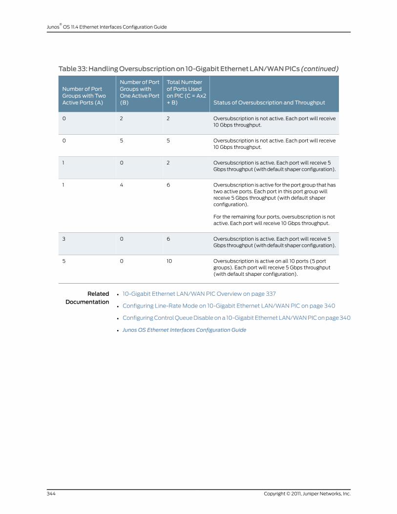
Table33:HandlingOversubscriptionon 10-GigabitEthernetLAN/WANPICs (continued)
Status of Oversubscription and Throughput
Total Numberof Ports UsedonPIC (C=Ax2+ B)
Number of PortGroups withOneActivePort(B)
Number of PortGroups with TwoActive Ports (A)
Oversubscription is not active. Each port will receive10 Gbps throughput.
220
Oversubscription is not active. Each port will receive10 Gbps throughput.
550
Oversubscription is active. Each port will receive 5Gbps throughput (with default shaper configuration).
201
Oversubscription is active for the port group that hastwo active ports. Each port in this port group willreceive 5 Gbps throughput (with default shaperconfiguration).
For the remaining four ports, oversubscription is notactive. Each port will receive 10 Gbps throughput.
641
Oversubscription is active. Each port will receive 5Gbps throughput (with default shaper configuration).
603
Oversubscription is active on all 10 ports (5 portgroups). Each port will receive 5 Gbps throughput(with default shaper configuration).
1005
RelatedDocumentation
• 10-Gigabit Ethernet LAN/WAN PIC Overview on page 337
• Configuring Line-Rate Mode on 10-Gigabit Ethernet LAN/WAN PIC on page 340
• Configuring Control Queue Disable on a 10-Gigabit Ethernet LAN/WAN PIC on page 340
• Junos OS Ethernet Interfaces Configuration Guide
Copyright © 2011, Juniper Networks, Inc.344
Junos®
OS 11.4 Ethernet Interfaces Configuration Guide

CHAPTER 23
Configuring the 10-Gigabit EthernetDWDM InterfaceWavelength
• 10-Gigabit Ethernet DWDM Interface Wavelength Overview on page 345
• Configuring the 10-Gigabit Ethernet DWDM Interface Wavelength on page 345
10-Gigabit Ethernet DWDM InterfaceWavelength Overview
For M320, M120, T320, and T640 routers, the 10-Gigabit Ethernet DWDM PIC enables
you to configure 10-Gigabit Ethernet DWDM interfaces with full C-band International
Telecommunication Union (ITU)-Grid tunable optics, as defined in the following
specifications:
• Intel TXN13600 Optical Transceiver I2C Interface and Customer EEPROM Preliminary
Specification, July 2004.
• I2C Reference Document for 300 Pin MSA 10G and 40G Transponder, Edition 4, August
04, 2003.
By default, the wavelength is 1550.12 nanometers (nm), which corresponds to 193.40
terahertz (THz).
RelatedDocumentation
Configuring the 10-Gigabit Ethernet DWDM Interface Wavelength on page 345•
• Junos OS Ethernet Interfaces Configuration Guide
Configuring the 10-Gigabit Ethernet DWDM InterfaceWavelength
To configure the wavelength on a 10-Gigabit Ethernet DWDM interface, include the
wavelength statement at the [edit interfaces ge-fpc/pic/port optics-options] hierarchy
level:
[edit interfaces ge-0/0/0 optics-options]wavelength nm;
For interface diagnostics, you can issue the show interfaces diagnostics optics ge-fpc/pic
/port operational mode command.
Table 34 on page 346 shows configurable wavelengths and the corresponding frequency
for each configurable wavelength.
345Copyright © 2011, Juniper Networks, Inc.

Table 34:Wavelength-to-Frequency ConversionMatrix
Frequency (THz)Wavelength(nm)Frequency (THz)
Wavelength(nm)Frequency (THz)
Wavelength(nm)
193.101552.52194.601540.56196.101528.77
193.001553.33194.501541.35196.001529.55
192.901554.13194.401542.14195.901530.33
192.801554.94194.301542.94195.801531.12
192.701555.75194.201543.73195.701531.90
192.601556.56194.101544.53195.601532.68
192.501557.36194.001545.32195.501533.47
192.401558.17193.901546.12195.401534.25
192.301558.98193.801546.92195.301535.04
192.201559.79193.701547.72195.201535.82
192.101560.61193.601548.52195.101536.61
192.001561.42193.501549.32195.001537.40
191.901562.23193.401550.12194.901538.19
191.801563.05193.301550.92194.801538.98
191.701563.86193.201551.72194.701539.77
RelatedDocumentation
• 10-Gigabit Ethernet DWDM Interface Wavelength Overview on page 345
• Junos OS Ethernet Interfaces Configuration Guide
Copyright © 2011, Juniper Networks, Inc.346
Junos®
OS 11.4 Ethernet Interfaces Configuration Guide

CHAPTER 24
Configuring 10-Gigabit Ethernet Framing
• 10-Gigabit Ethernet Framing Overview on page 347
• Configuring 10-Gigabit Ethernet Framing on page 347
• Understanding WAN Framing for 10-Gigabit Ethernet Trio Interfaces on page 348
10-Gigabit Ethernet Framing Overview
The 10-Gigabit Ethernet interfaces support operation in two modes:
• 10GBASE-R, LAN Physical Layer Device (LAN PHY)
• 10GBASE-W, WAN Physical Layer Device (WAN PHY)
When the external interface is running in LAN PHY mode, it bypasses the WIS sublayer
to directly stream block-encoded Ethernet frames on a 10-Gigabit Ethernet serial interface.
When the external interface is running in WAN PHY mode, it uses the WIS sublayer to
transport 10-Gigabit Ethernet frames in an OC192c SONET payload.
WAN PHY mode is supported on MX240, MX480, MX960, T640, and T1600 routers only.
Although the external interface provides a lower throughput when running in WAN PHY
mode because of the extra SONET overhead, it can interoperate with SONET section or
line level repeaters. This creates an advantage when the interface is used for
long-distance, point-to-point 10-Gigabit Ethernet links. When the external interface is
running in WAN PHY mode, some SONET options are supported. For information about
SONET options supported on this interface, see Configuring SONET/SDH Physical
Interface Properties.
RelatedDocumentation
Configuring SONET/SDH Physical Interface Properties•
• Configuring 10-Gigabit Ethernet Framing on page 347
• Understanding WAN Framing for 10-Gigabit Ethernet Trio Interfaces on page 348
• Junos OS Ethernet Interfaces Configuration Guide
Configuring 10-Gigabit Ethernet Framing
The 10-Gigabit Ethernet interfaces uses the interface type xe-fpc/pic/port. On single port
devices, the port number is always zero.
347Copyright © 2011, Juniper Networks, Inc.

The xe-fpc/pic/port interface inherits all the configuration commands that are used for
gigabit Ethernet (ge-fpc/pic/port) interfaces.
To configure LAN PHY or WAN PHY operating mode, include the framing statement with
the lan-phy or wan-phy option at the [edit interfaces xe-fpc /pic/0 ] hierarchy level.
[edit interfaces xe-fpc/pic/0 framing]framing (lan-phy | wan-phy);
To display interface information, use the operational mode command show interfaces
xe-fpc/pic/port extensive.
NOTE: If you configure theWAN PHYmode on an aggregated Ethernetinterface, youmust set the aggregated Ethernet link speed to OC192.
RelatedDocumentation
framing on page 452•
• 10-Gigabit Ethernet Framing Overview on page 347
• Understanding WAN Framing for 10-Gigabit Ethernet Trio Interfaces on page 348
• Junos OS Ethernet Interfaces Configuration Guide
UnderstandingWAN Framing for 10-Gigabit Ethernet Trio Interfaces
If you use the wan-phy statement option at the [edit interfaces xe-fpc/pic/0 framing]
hierarchy level to configure Trio WAN mode framing for 10-Gigabit Ethernet interfaces,
then the alarm behavior of the link, although in full compliance with the IEEE 802.3ae
10-Gigabit Ethernet standard, might not be as expected.
In particular:
• The interface does not distinguish between loss of light (LOL), loss of phase lock loop
(PLL), or loss of signal (LOS). If a loss of PLL or LOS alarm occurs, then both PLL and
LOS alarms are raised. LOL is also raised because there is no separate LOL indication
from the hardware.
• The interface does not raise LOS, PLL, or LOL alarms when the fiber in disconnected
from the interface port. You must remove the hardware to raise this alarm.
• The interface line-level alarm indicator signal (AIS-L) is not always raised in response
to a loss of framing (LOF) defect alarm.
• If the AIS-L or path-level AIS (AIS-P) occurs, the interface path-level loss of code
delineation (LCD-P) is not detected. LCD-P is seen during the path-level remote defect
indicator (RDI-P) alarm.
• If an AIS-L alarm occurs, the AIS-P is not detected, but the LOP alarm is detected.
None of the alarm issues are misleading, but they make troubleshooting the root cause
of problems more complex.
Copyright © 2011, Juniper Networks, Inc.348
Junos®
OS 11.4 Ethernet Interfaces Configuration Guide

RelatedDocumentation
• framing on page 452
• Configuring 10-Gigabit Ethernet Framing on page 347
• 10-Gigabit Ethernet Framing Overview on page 347
• Junos OS Ethernet Interfaces Configuration Guide
349Copyright © 2011, Juniper Networks, Inc.
Chapter 24: Configuring 10-Gigabit Ethernet Framing

Copyright © 2011, Juniper Networks, Inc.350
Junos®
OS 11.4 Ethernet Interfaces Configuration Guide

CHAPTER 25
Configuring 10-Gigabit EthernetNotification of Link Down Alarm
• 10-Gigabit Ethernet Notification of Link Down Alarm Overview on page 351
• Configuring 10-Gigabit Ethernet Notification of Link Down Alarm on page 351
10-Gigabit Ethernet Notification of Link Down AlarmOverview
Notification of link down alarm generation and transfer is supported for all 10-Gigabit
Ethernet PIC interfaces in M120, M320. and T Series routers.
RelatedDocumentation
Configuring 10-Gigabit Ethernet Notification of Link Down Alarm on page 351•
• Junos OS Ethernet Interfaces Configuration Guide
Configuring 10-Gigabit Ethernet Notification of Link Down Alarm
To configure this option, include the asynchronous-notification statement at the [edit
interfaces ge- fpc/pic/port gigether-options] hierarchy level:
[edit interfaces]ge-fpc/pic/port {gigether-options {asynchronous-notification;
}}
RelatedDocumentation
• 10-Gigabit Ethernet Notification of Link Down Alarm Overview on page 351
• Junos OS Ethernet Interfaces Configuration Guide
351Copyright © 2011, Juniper Networks, Inc.

Copyright © 2011, Juniper Networks, Inc.352
Junos®
OS 11.4 Ethernet Interfaces Configuration Guide
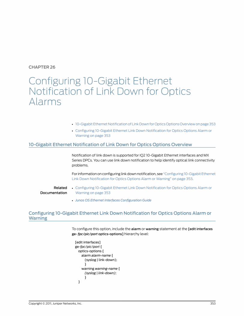
CHAPTER 26
Configuring 10-Gigabit EthernetNotification of Link Down for OpticsAlarms
• 10-Gigabit Ethernet Notification of Link Down for Optics Options Overview on page 353
• Configuring 10-Gigabit Ethernet Link Down Notification for Optics Options Alarm or
Warning on page 353
10-Gigabit Ethernet Notification of Link Down for Optics Options Overview
Notification of link down is supported for IQ2 10-Gigabit Ethernet interfaces and MX
Series DPCs. You can use link down notification to help identify optical link connectivity
problems.
For information on configuring link down notification, see “Configuring 10-Gigabit Ethernet
Link Down Notification for Optics Options Alarm or Warning” on page 353.
RelatedDocumentation
Configuring 10-Gigabit Ethernet Link Down Notification for Optics Options Alarm or
Warning on page 353
•
• Junos OS Ethernet Interfaces Configuration Guide
Configuring 10-Gigabit Ethernet Link DownNotification for Optics Options Alarm orWarning
To configure this option, include the alarm or warning statement at the [edit interfaces
ge- fpc/pic/port optics-options] hierarchy level:
[edit interfaces]ge-fpc/pic/port {optics-options {alarm alarm-name {(syslog | link-down);}
warningwarning-name {(syslog | link-down);}
}
353Copyright © 2011, Juniper Networks, Inc.

}
RelatedDocumentation
• alarm
• warning
• 10-Gigabit Ethernet Notification of Link Down for Optics Options Overview on page 353
• Junos OS Ethernet Interfaces Configuration Guide
Copyright © 2011, Juniper Networks, Inc.354
Junos®
OS 11.4 Ethernet Interfaces Configuration Guide

CHAPTER 27
Configuring 100-Gigabit Ethernet PICs
This section contains the following topics:
• 100-Gigabit Ethernet PIC Overview on page 355
• Configuring 100-Gigabit Ethernet PICs on page 358
• Configuring 100-Gigabit Ethernet PIC VLAN Steering Mode on page 361
100-Gigabit Ethernet PIC Overview
The 100-Gigabit Ethernet PIC is a 1-port 100-Gigabit Ethernet Type 4 PIC with 100-gigabit
small form-factor pluggable transceiver (CFP). The 100-Gigabit Ethernet PIC occupies
FPC slots 0 and 1 in the T1600-FPC4-ES FPC. This PIC is available only as packaged in
an assembly with the T1600-FPC4-ES FPC. For information on supported transceivers
and hardware, see 100-Gigabit Ethernet PIC with CFP (T1600 Router).
The 100-Gigabit Ethernet PIC supports flexible encapsulation and MAC accounting.
MAC learning, MAC policing, and Layer 2 rewrite functionality are not supported.
The ingress flow can be filtered based on the VLAN source and destination addresses.
Ingress frames can also be classified according to VLAN, stacked VLAN, source address,
VLAN source address, and stacked VLAN source address. VLAN manipulation on egress
frames are supported on both outer and inner VLAN tags.
The following features are supported:
• The following encapsulation protocols are supported:
• Layer 2 protocols
• Ethernet CCC, Ethernet TCC, Ethernet VPLS
• VLAN CCC
• Extended VLAN TCC
• VLAN VPLS
• Flexible Ethernet service
• Layer 3 protocols
355Copyright © 2011, Juniper Networks, Inc.

• IPv4
• Ipv6
• MPLS
• CFP MSA compliant MDIO control features (transceiver dependent).
• Graceful Routing Engine switchover (GRES) is supported in all PIC and chassis
configurations.
• Interface creation:
• When the PIC, is brought online, the router creates two 50 gigabit capable interfaces,
et-x/0/0:0 and et-x/0/0:1, where x represents the FPC slot number. Each physical
interface represents two internal 50 gigabit Ethernet Packet Forwarding Engines.
Two logical interfaces are configured under each physical interface.
• Packet Forwarding Engine 0 is physical interface 0, Packet Forwarding Engine 1 is
physical interface 1
• 802.3 link aggregation:
• Two logical interfaces are created for each 100-Gigabit Ethernet PIC. To utilize
bandwidth beyond 50 gigabits per second, an aggregate interface must be explicitly
configured on the 100-Gigabit Ethernet PIC that includes the two 50 gigabit interfaces.
• Each 100 gigabit Ethernet aggregate consumes one of the router-wide aggregated
Ethernet device pools. The number of 100-Gigabit Ethernet PICs cannot exceed the
router-wide limit, which is 128 for Ethernet.
• In each aggregate bundle, each 100-Gigabit Ethernet PIC consumes two members.
Hence, an aggregate bundle that consists purely of 100-Gigabit Ethernet PICs
supports a maximum of half of the software limit for the number of members.
Therefore, with a maximum of 16 links, up to 8 100-Gigabit Ethernet links are
supported.
• Combining 100-Gigabit Ethernet PICs into aggregate interfaces with other Ethernet
PICs is not permitted. However, other Ethernet PICs can also be configured within
the same T1600 with 100-Gigabit Ethernet PICs, and used in separate aggregate
interfaces.
• Multiple (Juniper Networks) Type 4 100-Gigabit Ethernet PICs on a T1600 router
can be combined into a static aggregated Ethernet bundle to connect to a different
type of 100 gigabit Ethernet PIC on a remote router (Juniper Networks or other
vendors). LACP is not supported in this configuration.
• Software Packet Forwarding Engine—Supports all Gigabit Ethernet PIC classification,
firewall filter, queuing model, and rewrite functionality.
• Egress traffic performance—Maximum egress throughput is 100 gigabits per second
on the physical interface, with 50 gigabits per second on the two assigned logical
interfaces.
Copyright © 2011, Juniper Networks, Inc.356
Junos®
OS 11.4 Ethernet Interfaces Configuration Guide

• Ingress traffic performance—Maximum ingress throughput is 100 gigabits per second
on the physical interface, with 50 gigabits per second on the two assigned logical
interfaces. To achieve 100 gigabits per second ingress traffic performance, use one of
the interoperability modes described below. For example, if VLAN steering mode is not
used when connecting to a remote 100 gigabits per second interface (that is on a
different 100 gigabits per second PIC on a Juniper Networks router or a different vendor’s
equipment), then all ingress traffic will try to use one of the 50 gigabits per second
Packet Forwarding Engines, rather than be distributed among the two 50 gigabits per
second Packet Forwarding Engines, resulting in a total of 50 gigabits per second ingress
performance.
• Interoperability modes—The 100-Gigabit Ethernet PIC supports interoperability with
through configuration in one of the following two forwarding option modes:
• SAmulticast mode—In this mode, the 100-Gigabit Ethernet PIC supports
interconnection with other Juniper Networks 100-Gigabit Ethernet PICs (Model:
PD-1CE-CFP) interfaces only.
• VLAN steering mode—In this mode, the 100-Gigabit Ethernet PIC supports
interoperability with 100 gigabit Ethernet interfaces from other vendors only.
RelatedDocumentation
Configuring 100-Gigabit Ethernet PICs on page 358•
• T1600 Core Router
• TX Matrix Plus Router
357Copyright © 2011, Juniper Networks, Inc.
Chapter 27: Configuring 100-Gigabit Ethernet PICs

Configuring 100-Gigabit Ethernet PICs
You can configure the following features on the 100-Gigabit Ethernet PIC:
• Flexible Ethernet services encapsulation
• Source address MAC filtering
• Destination address MAC filtering
• MAC accounting in RX
• Channels defined by two stacked VLAN tags
• Channels defined by flex-vlan-tagging
• IP service for stacked VLAN tags
The following features are not supported on the 100-Gigabit Ethernet PIC:
• Multiple TPID
• IP service for non-standard TPID
• MAC learning
• MAC policing
• Layer 2 rewrite
NOTE: For the 100-Gigabit Ethernet PIC, only the PIC0 online and offline CLI
commands are supported. ThePIC1 online and offlineCLI commands are not
supported.
Copyright © 2011, Juniper Networks, Inc.358
Junos®
OS 11.4 Ethernet Interfaces Configuration Guide

NOTE: Each 100-Gigabit Ethernet PIC creates two et- physical interfaces,
defined as 50-gigabit physical interfaces in the Routing Engine and PacketForwarding Engine. By default, these are independent physical interfacesand are not configured as an aggregated Ethernet interface.
The 100-Gigabit Ethernet PIC supports aggregated Ethernet configurationto achieve higher throughput capability, whereby configuration is similar tothe 1G/10G aggregated Ethernet interface configuration.
The 100-Gigabit Ethernet PIC has the following restrictions for aggregatedEthernet configuration:
• Both physical interfaces belonging to the same 100-Gigabit Ethernet PICmustbe included in the sameaggregatedEthernetphysical interfaces. Theaggregation of the 100-Gigabit Ethernet PIC interface is always an evennumber of physical interfaces.
• The 100-Gigabit Ethernet PIC physical interface cannot be configured inthe aggregated interface with any other type of physical interface.
• Themaximumsupported number of aggregated 100-Gigabit Ethernet PICinterfaces is half of the number that the Junos OS supports for 1G/10Gaggregated Ethernet. For example, if Junos OS supports 16 ports of10-gigabitEthernetaggregation, it supports8portsof 100-GigabitEthernetPIC aggregation. This is because each port of the 100-Gigabit Ethernet PICport using 2 physical interfaces (et-x/0/0:0 and et-x/0/0:1), where eachphysical interface represents 50 gigabits of traffic capacity.
359Copyright © 2011, Juniper Networks, Inc.
Chapter 27: Configuring 100-Gigabit Ethernet PICs

To configure a 100-Gigabit Ethernet PIC:
1. Perform the media configuration:
The 100-Gigabit Ethernet PIC features a 100 gigabit per second pipe. The media-related
configuration commands for et-x/0/0:0 and et-x/0/0:1 must both be configured at
the same time and configured with the same value, otherwise the commit operation
fails.
When configuring to activate or deactivate the interface, if the interface contains the
described media-related configuration, it must activate and deactivate both units 0
and 1 at the same time, otherwise the commit operation fails.
The following media configuration commands have the above described restriction:
• # set interfaces et-x/0/0:1 disable
• # set interfaces et-x/0/0:1 gigether-options loopback
• # set interfaces et-x/0/0:1 mtu yyy
Due to an MTU restriction, the vlan-tagging and flexible-vlan-tagging configuration
on et-x/0/0:0 and et-x/0/0:1 must be same, otherwise the commit operation fails.
2. Specify the logical interfaces:
a. Two physical interfaces are created when the 100-Gigabit Ethernet PIC is brought
online (et-x/0/0:0 and et-x/0/0:1, where x represents the FPC slot number). Each
physical interface represents two internal 50-gigabit Ethernet Packet Forwarding
Engines.
b. Two logical interfaces are configured under each physical interface: Packet
Forwarding Engine 0 is physical interface 0 and Packet Forwarding Engine 1 is
physical interface 1.
3. Configure the 802.3 link aggregation:
a. Two physical interfaces are created for each 100-Gigabit Ethernet PIC. To utilize
bandwidth beyond 50 gigabits, an aggregated interface must be explicitly
configured on the 100-Gigabit Ethernet PIC that includes these two 50-gigabit
interfaces.
b. Each 100-Gigabit Ethernet PIC aggregate consumes one of the router-wide
aggregated Ethernet device pools. In Junos OS with 100-Gigabit Ethernet PICs, you
cannot exceed the router limit of 128 Ethernet PICs.
c. In each aggregated bundle, each 100-Gigabit Ethernet PIC consumes two aggregate
members. Hence, an aggregated bundle consisting of only one 100-Gigabit Ethernet
PIC supports only up to half of the Junos OS limit for the number of members. The
Junos OS supports a maximum of 16 links for up to 8 100-Gigabit Ethernet PIC
links.
4. Configure the Packet Forwarding Engine features:
Copyright © 2011, Juniper Networks, Inc.360
Junos®
OS 11.4 Ethernet Interfaces Configuration Guide

a. The 100-Gigabit Ethernet PIC supports all classification, firewall filters, queuing
model, and rewrite functionality features of the Gigabit Ethernet PICs. To configure
these parameters, see “Configuring Gigabit Ethernet Policers” on page 313,
“Configuring MAC Address Filtering” on page 317, and “Stacking and Rewriting
Gigabit Ethernet VLAN Tags Overview” on page 125.
NOTE: Whenusingtheshowinterfacesextensivecommandwitha 100-Gigabit
Ethernet PIC, the “Filter statistics” section will not be displayed because thehardware does not include those counters.
RelatedDocumentation
100-Gigabit Ethernet PIC Overview on page 355•
• Configuring Gigabit Ethernet Policers on page 313
• Configuring MAC Address Filtering on page 317
• Stacking and Rewriting Gigabit Ethernet VLAN Tags Overview on page 125
Configuring 100-Gigabit Ethernet PIC VLAN SteeringMode
In Junos OS Release 10.4 and later, you can configure the 100-Gigabit Ethernet PIC to
interoperate with routers using 100 gigabit Ethernet interfaces from other vendors by
using the forwarding-mode statement with the vlan-steering option at the [edit chassis
fpcslotpicslot]hierarchy level. On ingress, the router compares the outer VLAN ID against
the user-defined VLAN ID and VLAN mask combination and steers the packet accordingly.
You can program a custom VLAN ID and corresponding mask for PFE0.
General information on the VLAN steering mode:
• In VLAN steering mode, the SA multicast parameters are not used for packet steering.
• In SA multicast bit steering mode, the VLAN ID and VLAN masks are not used for packet
steering.
• Configuration to set the packet distribution mode and VLAN steering rule is done
through CLI commands. Both CLI commands result in a PIC reboot.
• There are three possible tag types of ingress packet:
• Untagged ingress packet—The packet is sent to PFE1.
• Ingress packet with one VLAN—The packet is forwarded to the corresponding PFE
based on the VLAN ID.
• Ingress packet with two VLANs—The packet is forwarded to the corresponding PFE
based on the outer VLAN ID.
• If no VLAN rule is configured, all tagged packets are distributed to PFE0.
361Copyright © 2011, Juniper Networks, Inc.
Chapter 27: Configuring 100-Gigabit Ethernet PICs

• VLAN rules describe how the router distributes packets. Two VLAN rules are provided
by the CLI:
• Odd-Even rule—Odd number VLAN IDs go to PFE1; even number of VLAN IDs go to
PFE0.
• Hi-Low rule—VLAN IDs 1 through 2047 go to PFE0; VLAN IDs 2048 through 4096 go
to PFE1.
• When the 100-Gigabit Ethernet PIC is configured in VLAN steering mode, it can be
configured in a two physical interfaces mode or in aggregate Ethernet (AE) mode:
• Two physical interfaces mode—When the PIC is in the two physical interfaces mode,
it creates the physical interfaces et-x/0/0:0 and et-x/0/0:1. Each physical interface
can configure its own logical interface and VLAN. The CLI enforces the following
restrictions at the commit time:
• The VLAN ID configuration must comply with the selected VLAN rule.
• The previous restriction implies that the same VLAN ID cannot be configured on
both physical interfaces.
• AE mode—When the PIC is in aggregated Ethernet mode, the two physical interfaces
on the same PIC are aggregated into one AE physical interface. The PIC egress traffic
is based on an AE internal hash algorithm. The PIC ingress traffic steering is based
on the customized VLAN ID rule. The CLI enforces the following restrictions at the
commit time:
• The PICs AE working in VLAN steering mode includes both links of that PIC, and
only the links of that PIC.
• The PIC AE working in SA multicast steering mode can include more than one
100-Gigabit Ethernet PIC to achieve more than 100 gigabit Ethernet capacity.
To configure SA multicast mode, use the set chassis fpc slot pic slot forwarding-mode
sa-multicast command.
SAMulticast Mode To configure SA multicast mode on a Juniper Networks 100-Gigabit Ethernet PIC in FPC0, PIC 0 for interconnection with another Juniper Networks 100-Gigabit Ethernet PIC, usethe set chassis fpc slot pic slot forwarding-mode sa-multicast command. You can use theshow forwarding-mode command to view the resulting configuration, as follows:
[edit chassis fpc slot pic slot]user@host# show forwarding-modeforwarding-mode {sa-multicast;
}
Copyright © 2011, Juniper Networks, Inc.362
Junos®
OS 11.4 Ethernet Interfaces Configuration Guide

VLAN SteeringMode To configure the Juniper Networks 100-Gigabit Ethernet PIC for VLAN steering mode forinteroperation between a Juniper Networks 100-Gigabit Ethernet PIC in FPC 0, PIC 0 anda 100 gigabit Ethernet interface from another vendor’s router, use the set chassis fpc slotpicslot forwarding-modevlan-steering command with the vlan-rule (high-low|odd-even)statement. You can use the show forwarding-mode command to view the resultingconfiguration, as follows:
[edit chassis fpc slot pic slot]user@host# show forwarding-modeforwarding-mode {vlan-steering {vlan-rule odd-even;
}}
RelatedDocumentation
• forwarding-mode (100-Gigabit Ethernet) on page 451
• sa-multicast (100-Gigabit Ethernet) on page 506
• vlan-rule (100-Gigabit Ethernet) on page 535
• vlan-steering (100-Gigabit Ethernet) on page 536
363Copyright © 2011, Juniper Networks, Inc.
Chapter 27: Configuring 100-Gigabit Ethernet PICs

Copyright © 2011, Juniper Networks, Inc.364
Junos®
OS 11.4 Ethernet Interfaces Configuration Guide
CHAPTER 28
Configuring 40-Gigabit Ethernet PICs
This section contains the following topics:
• 40-Gigabit Ethernet PIC Overview on page 365
• Configuring 40-Gigabit Ethernet PICs on page 367
40-Gigabit Ethernet PIC Overview
The 40-Gigabit Ethernet PIC with CFP (PD-1XLE-CFP) is a 1-port 40-Gigabit Ethernet
Type 4 PIC with C form-factor pluggable transceiver (CFP) optics supported on T1600
and T640 routers. The 40-Gigabit Ethernet PIC occupies FPC slot 0 or 1 in the Type 4
FPC and it is similar to any regular PIC such as the 4-port 10-Gigabit Ethernet LAN/WAN
PIC with XFP (PD-4XGE-XFP) PIC. The CFP information appears under the PIC information
in the display output.
The 40-Gigabit Ethernet PIC supports flexible Ethernet services encapsulation and MAC
accounting.
MAC learning, MAC policing, and Layer 2 rewrite features are not supported.
The 40-Gigabit Ethernet PIC with CFP supports the following features:
• Encapsulation protocols such as:
• Layer 2 protocols
• Ethernet CCC, Ethernet TCC, Ethernet VPLS
• VLAN CCC
• Extended VLAN TCC
• VLAN VPLS
• Flexible Ethernet service
• Layer 3 protocols
• IPv4
• IPv6
365Copyright © 2011, Juniper Networks, Inc.

• MPLS
• CFP Multi-Source Agreement (MSA)-compliant Management Data Input/Output
(MDIO) control features (transceiver dependent).
• Graceful Routing Engine switchover (GRES) (in all PIC and chassis configurations).
• Interface creation:
• When the PIC is brought online, the router creates one interface, et-x/y/0, where x
represents the FPC slot number and y represents PIC slot number. The physical
interface represents internal Ethernet Packet Forwarding Engines.
• The FPC slot number ranges from 0 through 7 in T1600 and T640 routers. The PIC
slot numbers are 0 and 1.
• Packet Forwarding Engine 0 is the physical interface 0, and Packet Forwarding Engine
1 is the physical interface 1.
• 802.3 link aggregation:
• The configuration of the 40-Gigabit Ethernet PIC with CFP complies with that of the
existing 1-Gigabit or 10-Gigabit Ethernet PIC and aggregated Ethernet interfaces.
• An aggregate bundle that consists purely of 40-Gigabit Ethernet PICs supports a
maximum of 40-Gigabit Ethernet links depending on the system implementation.
For Junos OS configuration information about this PIC, see “Configuring 40-Gigabit
Ethernet PICs” on page 367. For hardware compatibility information, see the T1600 PICs
Supported topic in the T1600 Core Router hardware guide and the T640 PICs Supported
topic in the T640 Core Router hardware guide.
RelatedDocumentation
Configuring 40-Gigabit Ethernet PICs on page 367•
• T640 Core Router
• T1600 Core Router
• TX Matrix Plus Router
• T640 PICs Supported
• T1600 PICs Supported
Copyright © 2011, Juniper Networks, Inc.366
Junos®
OS 11.4 Ethernet Interfaces Configuration Guide

Configuring 40-Gigabit Ethernet PICs
You can configure the following features on the 40-Gigabit Ethernet PIC with CFP
(PD-1XLE-CFP):
• Flexible Ethernet services encapsulation
• Source address MAC filtering
• Destination address MAC filtering
• MAC accounting in RX and TX
• Multiple tag protocol ID (TPID) support
• Channels defined by two stacked VLAN tags
• Channels defined by flex-vlan-tagging
• IP service for stacked VLAN tags
• IP service for nonstandard TPID
The following features are not supported on the 40-Gigabit Ethernet PIC with CFP:
• MAC learning
• MAC policing
• Layer 2 rewrite
NOTE: Each 40-Gigabit Ethernet PIC with CFP creates a single et- physical
interface in the Routing Engine and Packet Forwarding Engine.
The 40-Gigabit Ethernet PIC with CFP supports aggregated Ethernetconfiguration to achieve higher throughput capability, whereby theconfiguration is similar to the 1-Gigabit or 10-Gigabit aggregated Ethernetinterface configuration. Amaximum of 40-Gigabit Ethernet PIC links can bebundled into a single aggregated Ethernet configuration depending on thesystem implementation.
To configure the 40-Gigabit Ethernet PIC with CFP:
1. Perform the media configuration.
The command used to configure the media for the 40-Gigabit Ethernet PIC with CFP
is the same as that for other Ethernet PICs, such as the 4-port 10-Gigabit Ethernet
PIC.
2. Specify the logical interfaces.
367Copyright © 2011, Juniper Networks, Inc.
Chapter 28: Configuring 40-Gigabit Ethernet PICs

A single physical interface is created when the 40-Gigabit Ethernet PIC with CFP is
brought online (et-x/y/0, where x represents the FPC slot number and y represents
the PIC slot number). For more information, see “Configuring a Logical Interface for
Access Mode” on page 75 and “Configuring a Logical Interface for Trunk Mode” on
page 76.
3. Configure the 802.3 link aggregation.
• You must explicitly configure an aggregated interface on the 40-Gigabit Ethernet
PIC with CFP that includes the 40-Gigabit Ethernet interfaces. For more information,
see “Configuring an Aggregated Ethernet Interface” on page 83.
• The configuration of the 40-Gigabit Ethernet PIC with CFP complies with the
configuration of the 1-Gigabit Ethernet PIC, 10-Gigabit Ethernet PIC, and the
aggregated Ethernet interfaces. In each aggregated bundle, Junos OS supports a
maximum of 40-Gigabit Ethernet links. For more information, see “Configuring an
Aggregated Ethernet Interface” on page 83 and “10-Gigabit Ethernet LAN/WAN PIC
Overview” on page 337.
4. Configure the Packet Forwarding Engine features.
The 40-Gigabit Ethernet PIC with CFP supports all classification, firewall filters, queuing
model, and rewrite functionality features of the Gigabit Ethernet PICs. To configure
these parameters, see “Configuring Gigabit Ethernet Policers” on page 313, “Configuring
MAC Address Filtering” on page 317, and “Stacking and Rewriting Gigabit Ethernet
VLAN Tags Overview” on page 125.
RelatedDocumentation
• 40-Gigabit Ethernet PIC Overview on page 365
• Configuring Gigabit Ethernet Policers on page 313
• Configuring MAC Address Filtering on page 317
• Stacking and Rewriting Gigabit Ethernet VLAN Tags Overview on page 125
Copyright © 2011, Juniper Networks, Inc.368
Junos®
OS 11.4 Ethernet Interfaces Configuration Guide

CHAPTER 29
Configuring Point-to-Point Protocol overEthernet
• PPPoE Overview on page 370
• Understanding PPPoE Service Name Tables on page 374
• Evaluation Order for Matching Client Information in PPPoE Service Name
Tables on page 379
• Benefits of Configuring PPPoE Service Name Tables on page 379
• Configuring PPPoE on page 380
• Disabling the Sending of PPPoE Keepalive Messages on page 388
• Configuring PPPoE Service Name Tables on page 388
• Creating a Service Name Table on page 389
• Configuring the Action Taken When the Client Request Includes an Empty Service
Name Tag on page 390
• Configuring the Action Taken for the Any Service on page 391
• Assigning a Service to a Service Name Table and Configuring the Action Taken When
the Client Request Includes a Non-zero Service Name Tag on page 392
• Assigning an ACI/ARI Pair to a Service Name and Configuring the Action Taken When
the Client Request Includes ACI/ARI Information on page 393
• Limiting the Number of Active PPPoE Sessions Established with a Specified Service
Name on page 394
• Reserving a Static PPPoE Interface for Exclusive Use by a PPPoE Client on page 395
• Enabling Advertisement of Named Services in PADO Control Packets on page 396
• Assigning a Service Name Table to a PPPoE Underlying Interface on page 396
• Example: Configuring a PPPoE Service Name Table on page 397
• Tracing PPPoE Operations on page 399
• Troubleshooting PPPoE Service Name Tables on page 401
• Verifying a PPPoE Configuration on page 403
369Copyright © 2011, Juniper Networks, Inc.

PPPoEOverview
The Point-to-Point Protocol over Ethernet (PPPoE) connects multiple hosts on an
Ethernet LAN to a remote site through a single customer premises equipment (CPE)
device. Hosts share a common digital subscriber line (DSL), a cable modem, or a wireless
connection to the Internet.
A J Series router can be configured as the CPE device for PPPoE connections. To use
PPPoE, you must configure the router as a PPPoE client, encapsulate PPP packets over
Ethernet, and initiate a PPPoE session.
NOTE: J4300 and J6300 routers with asymmetrical DSL (ADSL) PhysicalInterface Modules (PIMs) and symmetrical high-speed DSL (SHDSL) PIMscan use PPPoE over Asynchronous TransferMode (ATM) to connect throughDSL lines only, not for direct ATM connections. For information aboutconfiguring ADSL and SHDSL interfaces, see ATM-over-ADSL Overview andATM-over-SHDSL Overview.
M120, M320, and MX Series routers can be configured as a PPPoE access concentrator
server. To configure a PPPoE server on an M120, M320, or MX Series Ethernet logical
interface, specify PPPoE encapsulation, include thepp0 statement for the pseudo PPPoE
physical interface, and include the server statement in the PPPoE options under the
logical interface.
NOTE: PPPoE encapsulation is not supported onM120, M320, or MX Seriesrouters on an ATM2 IQ interface.
On the J Series router, PPPoE establishes a point-to-point connection between the client
(the Services Router) and the server, also called an access concentrator. Multiple hosts
can be connected to the Services Router, and their data can be authenticated, encrypted,
and compressed before the traffic is sent to the PPPoE session on the Services Router’s
Fast Ethernet or ATM-over-ADSL interface. PPPoE is easy to configure and enables
services to be managed on a per-user basis rather than on a per-site basis.
This overview contains the following topics:
• PPPoE Interfaces on page 370
• PPPoE Stages on page 371
• Optional CHAP Authentication on page 372
PPPoE Interfaces
The PPPoE interface to the access concentrator can be a Fast Ethernet interface on any
Services Router, a Gigabit Ethernet interface on J4350 and J6350 Services Routers, an
ATM-over-ADSL or ATM-over-SHDSL interface on all J Series Services Routers except
the J2300, or an ATM-over-SHDSL interface on a J2300 Services Router. The PPPoE
Copyright © 2011, Juniper Networks, Inc.370
Junos®
OS 11.4 Ethernet Interfaces Configuration Guide
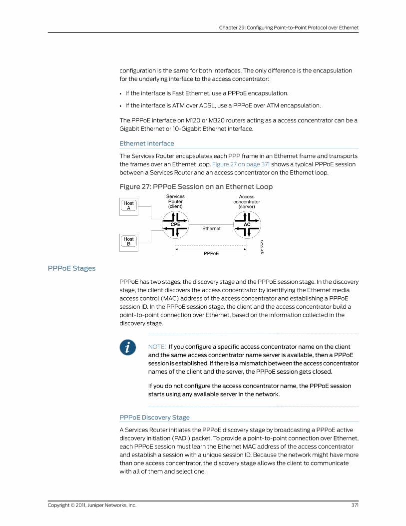
configuration is the same for both interfaces. The only difference is the encapsulation
for the underlying interface to the access concentrator:
• If the interface is Fast Ethernet, use a PPPoE encapsulation.
• If the interface is ATM over ADSL, use a PPPoE over ATM encapsulation.
The PPPoE interface on M120 or M320 routers acting as a access concentrator can be a
Gigabit Ethernet or 10-Gigabit Ethernet interface.
Ethernet Interface
The Services Router encapsulates each PPP frame in an Ethernet frame and transports
the frames over an Ethernet loop. Figure 27 on page 371 shows a typical PPPoE session
between a Services Router and an access concentrator on the Ethernet loop.
Figure 27: PPPoE Session on an Ethernet Loop
PPPoE Stages
PPPoE has two stages, the discovery stage and the PPPoE session stage. In the discovery
stage, the client discovers the access concentrator by identifying the Ethernet media
access control (MAC) address of the access concentrator and establishing a PPPoE
session ID. In the PPPoE session stage, the client and the access concentrator build a
point-to-point connection over Ethernet, based on the information collected in the
discovery stage.
NOTE: If you configure a specific access concentrator name on the clientand the same access concentrator name server is available, then a PPPoEsession isestablished. If there isamismatchbetweentheaccessconcentratornames of the client and the server, the PPPoE session gets closed.
If you do not configure the access concentrator name, the PPPoE sessionstarts using any available server in the network.
PPPoE Discovery Stage
A Services Router initiates the PPPoE discovery stage by broadcasting a PPPoE active
discovery initiation (PADI) packet. To provide a point-to-point connection over Ethernet,
each PPPoE session must learn the Ethernet MAC address of the access concentrator
and establish a session with a unique session ID. Because the network might have more
than one access concentrator, the discovery stage allows the client to communicate
with all of them and select one.
371Copyright © 2011, Juniper Networks, Inc.
Chapter 29: Configuring Point-to-Point Protocol over Ethernet
NOTE: A Services Router cannot receive PPPoE packets from two differentaccess concentrators on the same physical interface.
The PPPoE discovery stage consists of the following steps:
1. PPPoE active discovery initiation (PADI)—The client initiates a session by broadcasting
a PADI packet on the LAN to request a service.
2. PPPoE active discovery offer (PADO)—Any access concentrator that can provide the
service requested by the client in the PADI packet replies with a PADO packet that
contains it own name, the unicast address of the client, and the service requested. An
access concentrator can also use the PADO packet to offer other services to the client.
3. PPPoE active discovery request (PADR)—From the PADOs it receives, the client selects
one access concentrator based on its name or the services offered and sends it a
PADR packet to indicate the service or services needed.
4. PPPoE active discovery session-Confirmation (PADS)—When the selected access
concentrator receives the PADR packet, it accepts or rejects the PPPoE session.
• To accept the session, the access concentrator sends the client a PADS packet
with a unique session ID for a PPPoE session and a service name that identifies the
service under which it accepts the session.
• To reject the session, the access concentrator sends the client a PADS packet with
a service name error and resets the session ID to zero.
PPPoE Session Stage
The PPPoE session stage starts after the PPPoE discovery stage is over. The access
concentrator can start the PPPoE session after it sends the PADS packet to the client,
or the client can start the PPPoE session after it receives a PADS packet from the access
concentrator. A Services Router supports multiple PPPoE sessions on each interface,
but no more than 256 PPPoE sessions on all interfaces on the Services Router.
Each PPPoE session is uniquely identified by the Ethernet address of the peer and the
session ID. After the PPPoE session is established, data is sent as in any other PPP
encapsulation. The PPPoE information is encapsulated within an Ethernet frame and is
sent to a unicast address. In this stage, both the client and the server must allocate
resources for the PPPoE logical interface.
After a session is established, the client or the access concentrator can send a PPPoE
active discovery termination (PADT) packet anytime to terminate the session. The PADT
packet contains the destination address of the peer and the session ID of the session to
be terminated. After this packet is sent, the session is closed to PPPoE traffic.
Optional CHAP Authentication
For interfaces with PPPoE encapsulation, you can configure interfaces to support the
PPP Challenge Handshake Authentication Protocol (CHAP). When you enable CHAP on
an interface, the interface can authenticate its peer and be authenticated by its peer.
Copyright © 2011, Juniper Networks, Inc.372
Junos®
OS 11.4 Ethernet Interfaces Configuration Guide

If you configure an interface to handle incoming CHAP packets only (by including the
passive statement at the [edit interfaces interface-name ppp-options chap] hierarchy
level), the interface does not challenge its peer. However, if the interface is challenged,
it responds to the challenge. If you do not include the passive statement, the interface
always challenges its peer.
For more information about CHAP, see Configuring the PPP Challenge Handshake
Authentication Protocol.
RelatedDocumentation
Configuring the PPP Challenge Handshake Authentication Protocol•
• Developing a Log Storage Strategy
• Evaluation Order for Matching Client Information in PPPoE Service Name Tables on
page 379
• Benefits of Configuring PPPoE Service Name Tables on page 379
• Configuring PPPoE on page 380
• Disabling the Sending of PPPoE Keepalive Messages on page 388
• Configuring PPPoE Service Name Tables on page 388
• Creating a Service Name Table on page 389
• Configuring the Action Taken When the Client Request Includes an Empty Service
Name Tag on page 390
• Configuring the Action Taken for the Any Service on page 391
• Assigning a Service to a Service Name Table and Configuring the Action Taken When
the Client Request Includes a Non-zero Service Name Tag on page 392
• Assigning an ACI/ARI Pair to a Service Name and Configuring the Action Taken When
the Client Request Includes ACI/ARI Information on page 393
• Limiting the Number of Active PPPoE Sessions Established with a Specified Service
Name on page 394
• Reserving a Static PPPoE Interface for Exclusive Use by a PPPoE Client on page 395
• Enabling Advertisement of Named Services in PADO Control Packets on page 396
• Assigning a Service Name Table to a PPPoE Underlying Interface on page 396
• Example: Configuring a PPPoE Service Name Table on page 397
• Tracing PPPoE Operations on page 399
• Troubleshooting PPPoE Service Name Tables on page 401
• Verifying a PPPoE Configuration on page 403
• Junos OS Ethernet Interfaces Configuration Guide
373Copyright © 2011, Juniper Networks, Inc.
Chapter 29: Configuring Point-to-Point Protocol over Ethernet
Understanding PPPoE Service Name Tables
On an M120 router, M320 router, or MX Series router acting as a remote access
concentrator (AC), also referred to as a PPPoE server, you can configure up to 32 PPPoE
service name tables and assign the service name tables to PPPoE underlying interfaces.
A PPPoE service name table defines the set of services that the router can provide to a
PPPoE client. Service entries configured in a PPPoE service name table represent the
service name tags transmitted between the client and the router in a PPPoE control
packet.
This overview covers the following topics to help you understand and configure PPPoE
service name tables:
• Interaction Among PPPoE Clients and Routers During the Discovery Stage on page 374
• Service Entries and Actions in PPPoE Service Name Tables on page 375
• ACI/ARI Pairs in PPPoE Service Name Tables on page 376
• Dynamic Profiles and Routing Instances in PPPoE Service Name Tables on page 377
• Maximum Sessions Limit in PPPoE Service Name Tables on page 377
• Static PPPoE Interfaces in PPPoE Service Name Tables on page 378
• PADO Advertisement of Named Services in PPPoE Service Name Tables on page 378
Interaction Among PPPoE Clients and Routers During the Discovery Stage
In networks with mesh topologies, PPPoE clients are often connected to multiple PPPoE
servers (remote ACs). During the PPPoE discovery stage, a PPPoE client identifies the
Ethernet MAC address of the remote AC that can service its request, and establishes a
unique PPPoE session identifier for a connection to that AC.
The following steps describe, at a high level, how the PPPoE client and the remote AC
(router) use the PPPoE service name table to interact during the PPPoE discovery stage:
1. The PPPoE client broadcasts a PPPoE Active Discovery Initiation (PADI) control packet
to all remote ACs in the network to request that an AC support certain services.
The PADI packet must contain either, but not both, of the following:
• One and only one nonzero-length service name tag that represents a specific client
service
• One and only one empty (zero-length) service name tag that represents an
unspecified service
2. One or more remote ACs respond to the PADI packet by sending a PPPoE Active
Discovery Offer (PADO) packet to the client, indicating that the AC can service the
client request.
To determine whether it can service a particular client request, the router matches
the service name tag received in the PADI packet against the service name tags
configured in its service name table. If a matching service name tag is found in the
PPPoE service name table, the router sends the client a PADO packet that includes
Copyright © 2011, Juniper Networks, Inc.374
Junos®
OS 11.4 Ethernet Interfaces Configuration Guide

the name of the AC from which it was sent. If no matching service name tag is found
in the PPPoE service name table, the router drops the PADI request and does not send
a PADO response to the client.
3. The PPPoE client sends a unicast PPPoE Active Discovery Request (PADR) packet
to the AC to which it wants to connect, based on the responses received in the PADO
packets.
4. The selected AC sends a PPPoE Active Discovery Session (PADS) packet to establish
the PPPoE connection with the client.
Service Entries and Actions in PPPoE Service Name Tables
A PPPoE service name table can include three types of service entries: named services,
an empty service, and an any service. For each service entry, you specify the action to be
taken by the underlying interface when the router receives a PADI packet containing the
specified service name tag.
You can configure the following services and actions in a PPPoE service name table:
• Named service—Specifies a PPPoE client service that an AC can support. For example,
you might configure named services associated with different subscribers who log in
to the PPPoE server, such as user1-service or user2-service, or that correspond to
different ISP service level agreements, such as premium and standard. Each PPPoE
service name table can include a maximum of 512 named service entries, excluding
empty and any service entries. A named service is associated with the terminate action
by default.
• empty service—A service tag of zero length that represents an unspecified service. Each
PPPoE service name table includes one empty service. The empty service is associated
with the terminate action by default.
• any service—Acts as a default service for non-empty service entries that do not match
the named service entries or empty service entry configured in the PPPoE service name
table. Each PPPoE service name table includes one any service. The any service is
useful when you want to match the agent circuit identifier and agent remote identifier
information for a PPPoE client, but do not care about the contents of the service name
tag transmitted in the control packet. Theany service is associated with thedropaction
by default.
• Action—Specifies the action taken by the underlying PPPoE interface assigned to the
PPPoE service name table on receipt of a PADI packet from the client containing a
particular service request. You can configure one of the following actions for the
associated named service, empty service, any service, or agent circuit identifier/agent
remote identifier (ACI/ARI) pair in the PPPoE service name table on the router:
• terminate—(Default) Directs the router to immediately respond to the PADI packet
by sending the client a PADO packet containing the name of the AC that can service
the request. Named services, empty services, and ACI/ARI pairs are associated with
the terminateaction by default. Configuring the terminateaction for a service enables
you to more tightly control which PPPoE clients can access and receive services
from a particular PPPoE server.
375Copyright © 2011, Juniper Networks, Inc.
Chapter 29: Configuring Point-to-Point Protocol over Ethernet

• delay—Number of seconds that the PPPoE underlying interface waits after receiving
a PADI packet from the client before sending a PADO packet in response. In networks
with mesh topologies, you might want to designate a primary PPPoE server and a
backup PPPoE server for handling a particular service request. In such a scenario,
you can configure a delay for the associated service entry on the backup PPPoE
server to allow sufficient time for the primary PPPoE server to respond to the client
with a PADO packet. If the primary server does not send the PADO packet within the
delay period configured on the backup server, then the backup server sends the
PADO packet after the delay period expires.
• drop—Directs the router to drop (ignore) a PADI packet containing the specified
service name tag when received from a PPPoE client, which effectively denies the
client’s request to provide the associated service. The any service is associated with
the drop action by default. To prohibit the router from responding to PADI packets
that contain empty or any service name tags, you can configure the drop action for
the empty or any service. You can also use the drop action in combination with
ACI/ARI pairs to accept specific service name tags only from specific subscribers,
as described in the following information about ACI/ARI pairs.
ACI/ARI Pairs in PPPoE Service Name Tables
To specify agent circuit identifier (ACI) and agent remote identifier (ARI) information for
a named service, empty service, or any service in a PPPoE service name table, you can
configure an ACI/ARI pair. An ACI/ARI pair contains an agent circuit ID string that identifies
the DSLAM interface that initiated the service request, and an agent remote ID string that
identifies the subscriber on the DSLAM interface that initiated the service request. You
can think of an ACI/ARI pair as the representation of one or more PPPoE clients accessing
the router by means of the PPPoE service name table.
ACI/ARI specifications support the use of wildcard characters in certain formats. You
can configure a combined maximum of 8000 ACI/ARI pairs, both with and without
wildcards, per PPPoE service name table. You can distribute the ACI/ARI pairs in any
combination among the service entries in the service name table.
You must specify the action—terminate, delay, or drop—taken by the underlying PPPoE
interface when it receives a client request containing vendor-specific ACI/ARI information
that matches the ACI/ARI information configured in the PPPoE service name table on
the router. An ACI/ARI pair is associated with the terminate action by default.
For example, assume that for the user1-service named service, you configure the drop
action for the service and the terminate action for the associated ACI/ARI pairs. In this
case, the ACI/ARI pairs identify the DSLAM interfaces and associated subscribers
authorized to access the PPPoE server. Using this configuration causes the router to drop
PADI packets containing the user1-service tag unless the PADI packet also contains
vendor-specific ACI/ARI information that matches the subscribers identified in one or
more of the ACI/ARI pairs. For PADI packets containing matching ACI/ARI information,
the router sends an immediate PADO response to the client indicating that it can provide
the requested service for the specified subscribers.
Copyright © 2011, Juniper Networks, Inc.376
Junos®
OS 11.4 Ethernet Interfaces Configuration Guide
You can also associate a PPPoE dynamic profile, routing instance, and static PPPoE
interface with an ACI/ARI pair.
Dynamic Profiles and Routing Instances in PPPoE Service Name Tables
You can associate a previously configured PPPoE dynamic profile with a named service,
empty service, or any service in the PPPoE service name table, or with an ACI/ARI pair
defined for these services. The router uses the attributes defined in the profile to
instantiate a dynamic PPPoE subscriber interface based on the service name, ACI, and
ARI information provided by the PPPoE client during PPPoE negotiation. The dynamic
profile configured for a service entry or ACI/ARI pair in a PPPoE service name table
overrides the dynamic profile assigned to the PPPoE underlying interface on which the
dynamic PPPoE interface is created.
To specify the routing instance in which to instantiate the dynamic PPPoE interface, you
can associate a previously configured routing instance with a named service, empty
service, or any service in the PPPoE service name table, or with an ACI/ARI pair defined
for these services. Like dynamic profiles configured for service entries or ACI/ARI pairs,
the routing instance configured for the PPPoE service name table overrides the routing
instance assigned to the PPPoE underlying interface.
For information about configuring the PPPoE service name table to create a dynamic
PPPoE subscriber interface, see Assigning a Dynamic Profile and Routing Instance to a
Service Name or ACI/ARI Pair for Dynamic PPPoE Interface Creation in the Junos OS
Subscriber Access Configuration Guide.
MaximumSessions Limit in PPPoE Service Name Tables
To limit the number of PPPoE client sessions that can use a particular service entry in
the PPPoE service name table, you can configure the maximum number of active PPPoE
sessions using either dynamically-created or statically-created PPPoE interfaces that
the router can establish with a particular named service, empty service, or any service.
(You cannot configure the maximum sessions limit for an ACI/ARI pair.) The maximum
sessions limit must be in the range 1 through the platform-specific maximum PPPoE
sessions supported for your routing platform. The router maintains a count of active
PPPoE sessions for each service entry to determine when the maximum sessions limit
has been reached.
The router uses the maximum sessions value for a service entry in the PPPoE service
name table in conjunction with both of the following:
• The maximum sessions (max-sessions) value configured for the PPPoE underlying
interface
• The maximum number of PPPoE sessions supported on your routing platform
If your configuration exceeds either of these maximum session limits, the router cannot
establish the PPPoE session.
377Copyright © 2011, Juniper Networks, Inc.
Chapter 29: Configuring Point-to-Point Protocol over Ethernet

Static PPPoE Interfaces in PPPoE Service Name Tables
To reserve a previously configured static PPPoE interface for use only by the PPPoE client
with matching ACI/ARI information, you can specify a single static PPPoE interface for
each ACI/ARI pair defined for a named service entry, empty service entry, or any service
entry in a PPPoE service name table. (You cannot configure a static interface for a service
entry that does not have an ACI/ARI pair defined.) The static PPPoE interface associated
with an ACI/ARI pair takes precedence over the general pool of static PPPoE interfaces
associated with the PPPoE underlying interface configured on the router.
When you configure a static interface in the PPPoE service name table, make sure there
is a one-to-one correspondence between the PPPoE client and the static interface. For
example, if two clients have identical ACI/ARI information that matches the information
in the PPPoE service name table, the router reserves the static interface for exclusive use
by the first client that logs in to the router. As a result, the router prevents the second
client from logging in.
NOTE: You cannot configure a static interface for an ACI/ARI pair alreadyconfigured with a dynamic profile and routing instance. Conversely, youcannot configure a dynamic profile and routing instance for an ACI/ARI pairalready configured with a static interface.
PADOAdvertisement of Named Services in PPPoE Service Name Tables
By default, the advertisement of named services in PADO control packets sent by the
router to the PPPoE client is disabled. You can enable advertisement of named services
in the PADO packet as a global option when you configure the PPPoE protocol on the
router. Configuring PADO advertisement notifies PPPoE clients of the services that the
router (AC) can offer.
If you enable advertisement of named services in PADO packets, make sure the number
and length of all advertised service entries does not exceed the maximum transmission
unit (MTU) size supported by the PPPoE underlying interface.
RelatedDocumentation
Evaluation Order for Matching Client Information in PPPoE Service Name Tables on
page 379
•
• Benefits of Configuring PPPoE Service Name Tables on page 379
• Configuring PPPoE Service Name Tables on page 388
• Example: Configuring a PPPoE Service Name Table on page 397
• For information about creating dynamic PPPoE subscriber interfaces, see Configuring
Dynamic PPPoE Subscriber Interfaces Using Dynamic Profiles in the JunosOSSubscriber
Access Configuration Guide
• PPPoE Overview on page 370
• Junos OS Ethernet Interfaces Configuration Guide
Copyright © 2011, Juniper Networks, Inc.378
Junos®
OS 11.4 Ethernet Interfaces Configuration Guide
Evaluation Order for Matching Client Information in PPPoE Service Name Tables
When the router receives a service request from a PPPoE client, it evaluates the entries
configured in the PPPoE service name table to find a match for the client’s ACI/ARI
information so it can take the appropriate action.
The order of evaluation is as follows:
1. The router evaluates the ACI/ARI information configured for the any service entry, and
ignores the contents of the service name tag transmitted by the client.
2. If no match is found for the client information, the router evaluates the ACI/ARI
information for the empty service entry and the named service entries. If an ACI/ARI
pair is not configured for these service entries, the router evaluates the other attributes
configured for the empty service and named services.
3. If there is still no match for the client information, the router evaluates the other
attributes configured for theany service entry, and ignores both the ACI/ARI information
for the any service and the contents of the service name tag transmitted by the client.
If the any service is configured for the default action, drop, the router drops the PADR
packet. If the any service is configured for a nondefault action (terminate or delay),
the router evaluates the other attributes configured for the any service.
RelatedDocumentation
Understanding PPPoE Service Name Tables on page 374•
• Benefits of Configuring PPPoE Service Name Tables on page 379
• Configuring PPPoE Service Name Tables on page 388
• Example: Configuring a PPPoE Service Name Table for Dynamic Subscriber Interface
Creation
• PPPoE Overview on page 370
• Junos OS Ethernet Interfaces Configuration Guide
Benefits of Configuring PPPoE Service Name Tables
This topic describes the benefits of configuring PPPoE service name tables.
Configuring PPPoE service name tables provides the following benefits:
• Enables support for multiple services requested by PPPoE clients, and configuration
of an action for the underlying PPPoE interface to take (delay, drop, or terminate) upon
receipt of a PPPoE Active Discovery Initiation (PADI) packet requesting that service.
• Provides tighter control over which PPPoE clients can log in to and receive services
from a particular PPPoE server.
• Provides load balancing across a set of remote access concentrators (ACs) in a mesh
topology by enabling you to configure agent circuit identifier/agent remote identifier
(ACI/ARI) pairs for named, empty, and any service entries to specify the appropriate
AC to receive and service a particular PPPoE client request.
379Copyright © 2011, Juniper Networks, Inc.
Chapter 29: Configuring Point-to-Point Protocol over Ethernet

• Offers a more targeted approach to configuration of PPPoE sessions based on the
service name and ACI/ARI information provided by the PPPoE client during PPPoE
negotiation.
• Supports creation of dynamic PPPoE subscriber interfaces in a specified routing instance
based on configuration of a service entry or ACI/ARI pair in the PPPoE service name
table.
• Enables you to reserve a specified static PPPoE interface for use only by the PPPoE
client with matching ACI/ARI information.
• Enables you to specify the maximum number of PPPoE client sessions that can use a
particular service entry in the PPPoE service name table.
• Provides redundancy across a set of remote ACs in a mesh topology by enabling you
to configure a primary AC and a backup AC for handling a specific service request from
a PPPoE client.
For example, on the primary AC for handling a client service, you might configure the
terminate action for the associated service to direct the primary AC to immediately
send a PPPoE Active Discovery Offer (PADO) packet in response to a PADI packet
containing that service name tag. On the backup AC for the client service, you might
configure the delay action for the associated service to specify the number of seconds
the backup AC waits after receiving a PADI packet from the client before sending a
PADO packet in response. If the primary AC does not send a PADO packet to the client
within the delay period configured on the backup AC, then the backup AC sends the
PADO packet after the delay period expires.
RelatedDocumentation
Understanding PPPoE Service Name Tables on page 374•
• Configuring PPPoE Service Name Tables on page 388
• Example: Configuring a PPPoE Service Name Table on page 397
• PPPoE Overview on page 370
• Junos OS Ethernet Interfaces Configuration Guide
Configuring PPPoE
To configure PPPoE on a J Series Services Router, perform the following tasks:
1. Configure PPPoE encapsulation for an Ethernet interface or Ethernet over ATM
encapsulation for an ATM-over-ADSL interface.
2. If you are configuring ATM over ADSL, configure LLC encapsulation on the logical
interface.
3. Specify the logical Ethernet interface or the logical ATM interface as the underlying
interface for the PPPoE session.
4. Configure the operational mode as client.
5. Identify the access concentrator by a unique name.
Copyright © 2011, Juniper Networks, Inc.380
Junos®
OS 11.4 Ethernet Interfaces Configuration Guide
6. Optionally, specify how many seconds to wait before attempting to reconnect.
7. Provide a name for the type of service provided by the access concentrator.
8. Optionally, configure the maximum transmission unit (MTU) of the interface.
9. Configure the PPPoE interface address.
10. Configure the destination PPPoE interface address.
11. Optionally, configure the MTU size for the protocol family.
12. Optionally, disable the sending of keepalive messages on the logical interface.
To configure PPPoE on an M120 or M320 Multiservice Edge Router or MX Series Universal
Edge Router operating as an access concentrator, perform the following tasks:
1. Configure PPPoE encapsulation for an Ethernet interface.
2. Specify the logical Ethernet interface as the underlying interface for the PPPoE session.
3. Optionally, configure the maximum transmission unit (MTU) of the interface.
4. Configure the operational mode as server.
5. Configure the PPPoE interface address.
6. Configure the destination PPPoE interface address.
7. Optionally, configure the MTU size for the protocol family.
8. Optionally, configure one or more PPPoE service name tables and the action taken
for each service in the tables.
Setting the Appropriate Encapsulation on the PPPoE Interface
For PPPoE on an Ethernet interface, you must configure encapsulation on the logical
interface and use PPP over Ethernet encapsulation.
For PPPoE on an ATM-over-ADSL interface, you must configure encapsulation on both
the physical and logical interfaces. To configure encapsulation on an ATM-over-ADSL
physical interface, use Ethernet over ATM encapsulation. To configure encapsulation on
an ATM-over-ADSL logical interface, use PPPoE over AAL5 LLC encapsulation. LLC
encapsulation allows a single ATM virtual connection to transport multiple protocols.
NOTE: PPPoE encapsulation is not supported on anM120 orM320 router onan ATM2 IQ interface.
When you configure a point-to-point encapsulation such as PPP on a physical interface,
the physical interface can have only one logical interface (only one unit statement)
associated with it.
To configure physical interface properties, include the encapsulation statement at the
[edit interfaces interface-name] hierarchy level:
[edit interfaces interface-name]
381Copyright © 2011, Juniper Networks, Inc.
Chapter 29: Configuring Point-to-Point Protocol over Ethernet

encapsulation ethernet-over-atm;
To configure logical interface encapsulation properties, include the encapsulation
statement:
encapsulation ppp-over-ether;
You can include this statement at the following hierarchy levels:
• [edit interfaces interface-name unit logical-unit-number]
• [edit logical-systems logical-system-name interfaces interface-name unit
logical-unit-number]
Perform the task appropriate for the interface on which you are using PPPoE:
• Configuring PPPoE Encapsulation on an Ethernet Interface on page 382
• Configuring PPPoE Encapsulation on an ATM-over-ADSL Interface on page 382
Configuring PPPoE Encapsulation on an Ethernet Interface
Both the client and the server must be configured to support PPPoE. To configure PPPoE
encapsulation on an Ethernet interface, include the encapsulation statement:
encapsulation ppp-over-ether;
You can include this statement at the following hierarchy levels:
• [edit interfaces pp0 unit logical-unit-number]
• [edit logical-systems logical-system-name interfaces pp0 unit logical-unit-number]
Configuring PPPoE Encapsulation on an ATM-over-ADSL Interface
To configure the PPPoE encapsulation on a ATM-over-ADSL interface, perform the
following steps:
1. Include the encapsulation statement at the [edit interfaces interface-name] hierarchy
level, and specify ethernet-over-atm:
[edit interfaces pp0]encapsulation ethernet-over-atm;
2. Configure LLC encapsulation on the logical interface by including the encapsulation
statement and specifying ppp-over-ether-over-atm-llc:
encapsulation ppp-over-ether-over-atm-llc;
You can include this statement at the following hierarchy levels:
Copyright © 2011, Juniper Networks, Inc.382
Junos®
OS 11.4 Ethernet Interfaces Configuration Guide
• [edit interfaces pp0 unit logical-unit-number]
• [edit logical-systems logical-system-name interfaces pp0 unit logical-unit-number]
Configuring a PPPoE Interface
• Configuring the PPPoE Underlying Interface on page 383
• Identifying the Access Concentrator on page 384
• Configuring the PPPoE Automatic Reconnect Wait Timer on page 384
• Configuring the PPPoE Service Name on page 384
• Configuring the PPPoE Server Mode on page 384
• Configuring the PPPoE Client Mode on page 385
• Configuring the PPPoE Source and Destination Addresses on page 385
• Deriving the PPPoE Source Address From a Specified Interface on page 385
• Configuring the PPPoE IP Address by Negotiation on page 385
• Configuring the Protocol MTU PPPoE on page 386
• Example: Configuring a PPPoE Client Interface on a J Series Services Router on page 386
• Example: Configuring a PPPoE Server Interface on an M120 or M320 Router on page 387
NOTE: WhenyouconfigureastaticPPPoE logical interface, youmust includethe pppoe-options subhierarchy at the [edit interfaces pp0 unit
logical-unit-number] hierarchy level or at the [edit logical-systems
logical-system-name interfaces pp0 unit logical-unit-number] hierarchy level.
If youomit thepppoe-optionssubhierarchy fromtheconfiguration, thecommit
operation fails.
Configuring the PPPoE Underlying Interface
To configure the underlying Fast Ethernet, Gigabit Ethernet, 10-Gigabit Ethernet, or ATMinterface, include the underlying-interface statement:
underlying-interface interface-name;
You can include this statement at the following hierarchy levels:
• [edit interfaces pp0 unit logical-unit-number pppoe-options]
• [edit logical-systems logical-system-name interfaces pp0 unit logical-unit-number
pppoe-options]
Specify the logical Ethernet, Fast Ethernet, Gigabit Ethernet, 10-Gigabit Ethernet, or ATM
interface as the underlying interface—for example, at-0/0/1.0 (ATM VC), fe-1/0/1.0 (Fast
Ethernet interface), or ge-2/0/0 (Gigabit Ethernet interface).
383Copyright © 2011, Juniper Networks, Inc.
Chapter 29: Configuring Point-to-Point Protocol over Ethernet

Identifying the Access Concentrator
When configuring a PPPoE client, identify the access concentrator by a unique name byincluding the access-concentrator statement:
access-concentrator name;
You can include this statement at the following hierarchy levels:
• [edit interfaces pp0 unit logical-unit-number pppoe-options]
• [edit logical-systems logical-system-name interfaces pp0 unit logical-unit-number
pppoe-options]
Configuring the PPPoE Automatic ReconnectWait Timer
By default, after a PPPoE session is terminated, the session attempts to reconnectimmediately. When configuring a PPPoE client, you can specify how many seconds towait before attempting to reconnect, by including the auto-reconnect statement:
auto-reconnect seconds;
You can include this statement at the following hierarchy levels:
• [edit interfaces pp0 unit logical-unit-number pppoe-options]
• [edit logical-systems logical-system-name interfaces pp0 unit logical-unit-number
pppoe-options]
You can configure the reconnection attempt to occur in 0 through 4,294,967,295 seconds
after the session terminates.
Configuring the PPPoE Service Name
When configuring a PPPoE client, identify the type of service provided by the accessconcentrator—such as the name of the Internet service provider (ISP), class, or qualityof service—by including the service-name statement:
service-name name;
You can include this statement at the following hierarchy levels:
• [edit interfaces pp0 unit logical-unit-number pppoe-options]
• [edit logical-systems logical-system-name interfaces pp0 unit logical-unit-number
pppoe-options]
Configuring the PPPoE Server Mode
When configuring a PPPoE server, identify the mode by including the server statement:
server;
You can include this statement at the following hierarchy levels:
• [edit interfaces pp0 unit logical-unit-number pppoe-options]
Copyright © 2011, Juniper Networks, Inc.384
Junos®
OS 11.4 Ethernet Interfaces Configuration Guide
• [edit logical-systems logical-system-name interfaces pp0 unit logical-unit-number
pppoe-options]
Configuring the PPPoE Client Mode
When configuring a PPPoE client, identify the mode by including the client statement:
client;
You can include this statement at the following hierarchy levels:
• [edit interfaces pp0 unit logical-unit-number pppoe-options]
• [edit logical-systems logical-system-name interfaces pp0 unit logical-unit-number
pppoe-options]
Configuring the PPPoE Source and Destination Addresses
When configuring a PPPoE client or server, assign source and destination addresses—forexample, 192.168.1.1/32 and 192.168.1.2. To assign the source and destination address,include the address and destination statements:
address address {destination address;
}
You can include these statements at the following hierarchy levels:
• [edit interfaces pp0.0 family inet]
• [edit logical-systems logical-system-name interfaces pp0.0 family inet]
Deriving the PPPoE Source Address From a Specified Interface
For a router supporting PPPoE, you can derive the source address from a specifiedinterface—for example, the loopback interface, lo0.0—and assign a destinationaddress—for example, 192.168.1.2. The specified interface must include a logical unitnumber and have a configured IP address. To derive the source address and assign thedestination address, include the unnumbered-address and destination statements:
unnumbered-address interface-name destination address;}
You can include these statements at the following hierarchy levels:
• [edit interfaces pp0.0 family inet]
• [edit logical-systems logical-system-name interfaces pp0.0 family inet]
Configuring the PPPoE IP Address by Negotiation
You can have the PPPoE client router obtain an IP address by negotiation with the remoteend. This method might require the access concentrator to use a RADIUS authenticationserver. To obtain an IP address from the remote end by negotiation, include thenegotiate-address statement:
negotiate-address;
385Copyright © 2011, Juniper Networks, Inc.
Chapter 29: Configuring Point-to-Point Protocol over Ethernet
You can include this statement at the following hierarchy levels:
• [edit interfaces pp0.0 family (inet | inet6 | mpls)]
• [edit logical-systems logical-system-name interfaces pp0.0 family (inet | inet6 | mpls)]
Configuring the Protocol MTU PPPoE
You can configure the maximum transmission unit (MTU) size for the protocol family.Specify a range from 0 through 5012 bytes. Ensure that the size of the media MTU isequal to or greater than the sum of the protocol MTU and the encapsulation overhead.To set the MTU, include the mtu statement:
mtu bytes;
You can include this statement at the following hierarchy levels:
• [edit interfaces pp0.0 family (inet | inet6 | mpls)]
• [edit logical-systems logical-system-name interfaces pp0.0 family (inet | inet6 | mpls)]
You can modify the MTU size of the interface by including the mtu bytes statement at
the [edit interfaces pp0] hierarchy level:
[edit interfaces pp0]mtu bytes;
The default media MTU size used and the range of available sizes on a physical interface
depends on the encapsulation used on that interface.
Example: Configuring a PPPoE Client Interface on a J Series Services Router
Configure a PPPoE over ATM-over-ADSL interface:
[edit interfaces]at-2/0/0 {encapsulation ethernet-over-atm;atm-options {vpi 0;
}dsl-options {operating-mode auto;
}unit 0 {encapsulation ppp-over-ether-over-atm-llc;vci 0.120;
}}pp0 {mtu 1492;unit 0 {ppp-options {chap {access-profile A-ppp-client;local-name A-at-2/0/0.0;
}}
Copyright © 2011, Juniper Networks, Inc.386
Junos®
OS 11.4 Ethernet Interfaces Configuration Guide
pppoe-options {underlying-interface at-2/0/0;client;access-concentrator ispl.com;service-name "[email protected]";auto-reconnect 100;
}no-keepalives;family inet {negotiate-address;mtu 100;
}family inet6 {negotiate-address;mtu 200;
}family mpls {negotiate-address;mtu 300;
}}
}
Example: Configuring a PPPoE Server Interface on anM120 or M320 Router
Configure a PPPoE server over a Gigabit Ethernet interface:
[edit interfaces]ge-1/0/0 {vlan-tagging;unit 1 {encapsulation ppp-over-ether;vlan-id 10;
}}pp0 {unit 0 {pppoe-options {underlying-interface ge-1/0/0.0;server;
}ppp-options {}family inet {address 22.2.2.1/32 {destination 22.2.2.2;
}}
}}
RelatedDocumentation
PPPoE Overview on page 370•
• Junos OS Ethernet Interfaces Configuration Guide
387Copyright © 2011, Juniper Networks, Inc.
Chapter 29: Configuring Point-to-Point Protocol over Ethernet
Disabling the Sending of PPPoE Keepalive Messages
When configuring the client, you can disable the sending of keepalive messages on alogical interface by including the no-keepalives statement:
no-keepalives;
You can include this statement at the following hierarchy levels:
• [edit interfaces pp0 unit logical-unit-number]
• [edit logical-systems logical-system-name interfaces pp0 unit logical-unit-number]
RelatedDocumentation
PPPoE Overview on page 370•
• Junos OS Ethernet Interfaces Configuration Guide
Configuring PPPoE Service Name Tables
To configure PPPoE service name tables:
1. Create a PPPoE service name table.
See “Creating a Service Name Table” on page 389.
2. (Optional) Configure the action taken for the empty service.
See “Configuring the Action Taken When the Client Request Includes an Empty Service
Name Tag” on page 390.
3. (Optional) Configure the action taken for the any service.
See “Configuring the Action Taken for the Any Service” on page 391.
4. Assign a named service to the service name table and optionally configure the action
taken for the specified service name.
See “Assigning a Service to a Service Name Table and Configuring the Action Taken
When the Client Request Includes a Non-zero Service Name Tag” on page 392.
5. (Optional) Configure the action taken for an ACI/ARI pair associated with a service.
See “Assigning an ACI/ARI Pair to a Service Name and Configuring the Action Taken
When the Client Request Includes ACI/ARI Information” on page 393.
6. (Optional) Assign a dynamic profile and routing instance to a service name or ACI/ARI
pair to instantiate a dynamic PPPoE subscriber interface.
See Assigning a Dynamic Profile and Routing Instance to a Service Name or ACI/ARI
Pair for Dynamic PPPoE Interface Creation.
7. (Optional) Limit the number of active PPPoE sessions that the router can establish
with the specified service.
See “Limiting the Number of Active PPPoE Sessions Established with a Specified
Service Name” on page 394.
Copyright © 2011, Juniper Networks, Inc.388
Junos®
OS 11.4 Ethernet Interfaces Configuration Guide

8. (Optional) Assign a static PPPoE interface to an ACI/ARI pair to reserve the interface
for exclusive use by the PPPoE client with matching ACI/ARI information.
See “Reserving a Static PPPoE Interface for Exclusive Use by a PPPoE Client” on
page 395.
9. (Optional) Enable advertisement of named services in the PADO control packet sent
by the router to the client.
See “Enabling Advertisement of Named Services in PADO Control Packets” on page 396.
10. Assign a service name table to a PPPoE underlying interface.
See “Assigning a Service Name Table to a PPPoE Underlying Interface” on page 396.
11. (Optional) Configure trace options for troubleshooting the configuration.
See “Tracing PPPoE Operations” on page 399.
RelatedDocumentation
Understanding PPPoE Service Name Tables on page 374•
• Benefits of Configuring PPPoE Service Name Tables on page 379
• Example: Configuring a PPPoE Service Name Table on page 397
• PPPoE Overview on page 370
• Junos OS Ethernet Interfaces Configuration Guide
Creating a Service Name Table
You can create up to 32 PPPoE service name tables on the router. You can optionally
create named services and add them to a service name table. By default, the empty
service and the any service are present in each service name table.
A named service specifies a PPPoE client service that the router, functioning as an access
concentrator or PPPoE server, can support. The empty service is a service tag of zero
length that represents an unspecified service. The any service acts as a default service
for non-empty service entries that do not match the named or empty service entries
configured in the PPPoE service name table. Named services and the empty service are
associated with the terminate action by default, and the any service is associated with
the drop action by default.
To create a PPPoE service name table:
• Specify the table name.
[edit protocols pppoe]user@host# set service-name-tables table1
RelatedDocumentation
Configuring PPPoE Service Name Tables on page 388•
• Understanding PPPoE Service Name Tables on page 374
• PPPoE Overview on page 370
389Copyright © 2011, Juniper Networks, Inc.
Chapter 29: Configuring Point-to-Point Protocol over Ethernet

• Junos OS Ethernet Interfaces Configuration Guide
Configuring the Action TakenWhen the Client Request Includes an Empty ServiceName Tag
You can configure the action taken by the PPPoE underlying interface when it receives
a PADI packet that includes a zero-length (empty) service name tag. The empty service
is present by default in every PPPoE service name table.
To indicate that it can service the client request, the interface returns a PADO packet in
response to the PADI packet. By default, the interface immediately responds to the
request; this is the terminate action. Alternatively, you can configure the drop action to
ignore (drop) the PADI packet, or the delay action to set a delay between receipt of the
PADI packet and transmission of the PADO packet.
(Optional) To configure the action taken for the empty service in response to a PADI
packet from a PPPoE client:
• Specify the action.
[edit protocols pppoe service-name-tables table1]user@host# set service empty drop
You can also accomplish the following optional tasks when you configure the empty
service:
• Specify the agent circuit identifier (ACI) and agent remote identifier (ARI) information
to determines the action taken by the PPPoE underlying interface when it receives a
PADI packet with matching ACI/ARI information.
• Specify a dynamic profile and routing instance with which the router instantiates a
dynamic PPPoE subscriber interface.
• Limit the number of active PPPoE sessions that the router can establish with theempty
service.
RelatedDocumentation
Understanding PPPoE Service Name Tables on page 374•
• Configuring PPPoE Service Name Tables on page 388
• Assigning an ACI/ARI Pair to a Service Name and Configuring the Action Taken When
the Client Request Includes ACI/ARI Information on page 393
• Assigning a Dynamic Profile and Routing Instance to a Service Name or ACI/ARI Pair
for Dynamic PPPoE Interface Creation
• Limiting the Number of Active PPPoE Sessions Established with a Specified Service
Name on page 394
• PPPoE Overview on page 370
• Junos OS Ethernet Interfaces Configuration Guide
Copyright © 2011, Juniper Networks, Inc.390
Junos®
OS 11.4 Ethernet Interfaces Configuration Guide
Configuring the Action Taken for the Any Service
The any service acts as a default service for service name tags transmitted by the client
that do not match any of the service entries configured in the PPPoE service name table
on the router. By configuring an action for the any service, you specify the action taken
by the PPPoE underlying interface when it receives a PADI control packet from a client
that includes a non-empty service name tag that does not match any of the named
service entries or empty service entry in the PPPoE service name table.
Each PPPoE service name table includes one any service entry associated by default
with the drop action. The drop action ignores a PADI packet containing a nonmatching
service name tag. Alternatively, you can configure the terminate action to immediately
respond to the PADI packet with a PADO packet, or the delay action to specify a delay
between receipt of the PADI packet and transmission of the PADO packet.
To configure the action taken for the any service in response to a PADI packet from a
PPPoE client:
• Specify the action.
[edit protocols pppoe service-name-tables table1]user@host# set service any terminate
You can also accomplish the following optional tasks when you configure theany service:
• Specify the agent circuit identifier (ACI) and agent remote identifier (ARI) information
to determine the action taken by the PPPoE underlying interface when it receives a
PADI packet with matching ACI/ARI information.
• Specify a dynamic profile and routing instance with which the router instantiates a
dynamic PPPoE subscriber interface.
• Limit the number of active PPPoE sessions that the router can establish with the any
service.
RelatedDocumentation
Understanding PPPoE Service Name Tables on page 374•
• Configuring PPPoE Service Name Tables on page 388
• Assigning an ACI/ARI Pair to a Service Name and Configuring the Action Taken When
the Client Request Includes ACI/ARI Information on page 393
• Assigning a Dynamic Profile and Routing Instance to a Service Name or ACI/ARI Pair
for Dynamic PPPoE Interface Creation
• Limiting the Number of Active PPPoE Sessions Established with a Specified Service
Name on page 394
• PPPoE Overview on page 370
• Junos OS Ethernet Interfaces Configuration Guide
391Copyright © 2011, Juniper Networks, Inc.
Chapter 29: Configuring Point-to-Point Protocol over Ethernet
Assigning a Service to a Service Name Table and Configuring the Action TakenWhenthe Client Request Includes a Non-zero Service Name Tag
You can configure a maximum of 512 named service entries, excluding empty and any
service entries, across all PPPoE service name tables on the router. A named service
specifies a PPPoE client service that the router, functioning as an access concentrator
or PPPoE server, can support. You can optionally configure the action taken by the PPPoE
underlying interface when it receives a PADI packet that includes a matching named
service (service name tag).
To indicate that it can service the client request, the interface returns a PADO packet in
response to the PADI packet. By default, the interface immediately responds to the
request; this is the terminate action. Alternatively, you can configure the drop action to
ignore (drop) the PADI packet, or the delay action to set a delay between receipt of the
PADI packet and transmission of the PADO packet.
(Optional) To configure a named service for a PPPoE service name table, do one of the
following:
• Assign a service name to the table. The terminate action is applied to the service by
default.
[edit protocols pppoe service-name-tables table1]user@host# set service gold-service
• Specify the action taken for a service in response to a PADI packet from a PPPoE client.
[edit protocols pppoe service-name-tables table1]user@host# set service gold-service delay 25
You can also accomplish the following optional tasks when you configure a named
service:
• Specify the agent circuit identifier (ACI) and agent remote identifier (ARI) information
to determines the action taken by the PPPoE underlying interface when it receives a
PADI packet with matching ACI/ARI information.
• Specify a dynamic profile and routing instance with which the router instantiates a
dynamic PPPoE subscriber interface.
• Limit the number of active PPPoE sessions that the router can establish with the
specified named service.
RelatedDocumentation
Understanding PPPoE Service Name Tables on page 374•
• Configuring PPPoE Service Name Tables on page 388
• Assigning an ACI/ARI Pair to a Service Name and Configuring the Action Taken When
the Client Request Includes ACI/ARI Information on page 393
• Assigning a Dynamic Profile and Routing Instance to a Service Name or ACI/ARI Pair
for Dynamic PPPoE Interface Creation
Copyright © 2011, Juniper Networks, Inc.392
Junos®
OS 11.4 Ethernet Interfaces Configuration Guide

• Limiting the Number of Active PPPoE Sessions Established with a Specified Service
Name on page 394
• PPPoE Overview on page 370
• Junos OS Ethernet Interfaces Configuration Guide
Assigning an ACI/ARI Pair to a Service Name and Configuring the Action TakenWhenthe Client Request Includes ACI/ARI Information
You can configure up to 8000 agent circuit identifier/agent remote identifier (ACI/ARI)
pairs per PPPoE service name table, distributed in any combination among the named,
empty, and any service entries in the service name table. You can optionally configure
the action taken by the PPPoE underlying interface when it receives a PADI packet that
includes a service name tag and the vendor-specific tag with ACI/ARI information that
matches the ACI/ARI pair that you specify.
You can use an asterisk (*) as a wildcard character to match ACI/ARI pairs, the ACI alone,
or the ARI alone. The asterisk can be placed only at the beginning, the end, or both the
beginning and end of the identifier string. You can also specify an asterisk alone for either
the ACI or the ARI. You cannot specify only an asterisk for both the ACI and the ARI. When
you specify a single asterisk as the identifier, that identifier is ignored in the PADI packet.
For example, suppose you care about matching only the ACI and do not care what value
the ARI has in the PADI packet, or even whether the packet contains an ARI value. In this
case you can set the remote-id-string to a single asterisk. Then the interface ignores the
ARI received in the packet and the interface takes action based only on matching the
specified ACI.
To indicate that it can service the client request, the interface returns a PADO packet in
response to the PADI packet. By default, the interface immediately responds to the
request; this is the terminate action. Alternatively, you can configure the drop action to
ignore (drop) the PADI packet, or the delay action to set a delay between receipt of the
PADI packet and transmission of the PADO packet.
To configure an ACI/ARI pair for a named, empty, or any service, do one of the following:
• Assign an ACI/ARI pair to the service name. The terminate action is applied to the pair
by default.
[edit protocols pppoe service-name-tables table1]user@host# set service gold-service agent-specifier aci DSLAM:3/0/1/101 ari *user*
• Specify the action taken for the ACI/ARI pair in response to a PADI packet from a PPPoE
client.
[edit protocols pppoe service-name-tables table1]user@host# set service any agent-specifier aci velorum-ge-2/0/3 ari westford delay90
In this example, an ACI/ARI pair and the delay action are configured for the any service.
Configuring an ACI/ARI pair for the any service is useful when you want to match the
agent circuit identifier and agent remote identifier information for a specific PPPoE
393Copyright © 2011, Juniper Networks, Inc.
Chapter 29: Configuring Point-to-Point Protocol over Ethernet

client, but do not care about the contents of the service name tag transmitted by the
client in the PADI packet.
You can also accomplish the following optional tasks when you configure an ACI/ARI
pair:
• Specify a dynamic profile and routing instance with which the router instantiates a
dynamic PPPoE subscriber interface.
• Reserve a specified static PPPoE interface for exclusive use by the PPPoE client with
match ACI/ARI information.
RelatedDocumentation
Understanding PPPoE Service Name Tables on page 374•
• Configuring PPPoE Service Name Tables on page 388
• Assigning a Dynamic Profile and Routing Instance to a Service Name or ACI/ARI Pair
for Dynamic PPPoE Interface Creation
• Reserving a Static PPPoE Interface for Exclusive Use by a PPPoE Client on page 395
• PPPoE Overview on page 370
• Junos OS Ethernet Interfaces Configuration Guide
Limiting the Number of Active PPPoE Sessions Establishedwith a Specified ServiceName
To limit the number of PPPoE client sessions that can use a particular service entry in
the PPPoE service name table, you can configure the maximum number of PPPoE sessions
using static or dynamic PPPoE interfaces that the router can establish with the specified
named service, empty service, or any service. You cannot configure a maximum sessions
limit for an ACI/ARI pair in the service name table.
The maximum sessions limit must be in the range 1 through the platform-specific
maximum PPPoE sessions supported for your routing platform. The router maintains a
count of active PPPoE sessions for each service entry to determine when the maximum
sessions limit has been reached.
To limit the number of PPPoE client sessions for a particular named,empty, orany service:
• Configure the maximum sessions limit for the specified service:
[edit protocols pppoe service-name-tables tableEast]user@host# set service premium-servicemax-sessions 100
RelatedDocumentation
Understanding PPPoE Service Name Tables on page 374•
• Configuring PPPoE Service Name Tables on page 388
• PPPoE Overview on page 370
• Junos OS Ethernet Interfaces Configuration Guide
Copyright © 2011, Juniper Networks, Inc.394
Junos®
OS 11.4 Ethernet Interfaces Configuration Guide

Reserving a Static PPPoE Interface for Exclusive Use by a PPPoE Client
To reserve a static PPPoE interface for exclusive use by the PPPoE client with matching
agent circuit identifier/agent remote identifier (ACI/ARI) information, you can assign a
previously configured static PPPoE interface to an ACI/ARI pair defined for a named
service entry, empty service entry, or any service entry in a PPPoE service name table.
You cannot assign a static PPPoE interface directly to a service entry that does not have
an ACI/ARI pair defined.
Observe the following guidelines when you configure a static PPPoE interface for an
ACI/ARI pair:
• You can specify only one static PPPoE interface per ACI/ARI pair.
• If the ACI/ARI pair represents an individual PPPoE client, make sure there is a one-to-one
correspondence between the client and the static PPPoE interface.
• The static interface associated with the ACI/ARI pair takes precedence over the general
pool of static interfaces associated with the PPPoE underlying interface.
• You cannot configure a static interface for an ACI/ARI pair already configured with a
dynamic profile and routing instance. Conversely, you cannot configure a dynamic
profile and routing instance for an ACI/ARI pair already configured with a static interface.
Before you begin:
• Configure the static PPPoE interface on a M120, M320, or MX Series router.
See “Configuring PPPoE” on page 380.
To reserve a static PPPoE interface for exclusive use by the PPPoE client with matching
ACI/ARI information:
• Assign a previously configured static PPPoE interface to the ACI/ARI pair defined for
a named, empty, or any service entry:
[edit protocols pppoe service-name-tables tableEast]user@host# set service any agent-specifier aci velorum-ge-2/0/3 ari westfordstatic-interface pp0.100
RelatedDocumentation
Understanding PPPoE Service Name Tables on page 374•
• Configuring PPPoE Service Name Tables on page 388
• PPPoE Overview on page 370
• Junos OS Ethernet Interfaces Configuration Guide
395Copyright © 2011, Juniper Networks, Inc.
Chapter 29: Configuring Point-to-Point Protocol over Ethernet
Enabling Advertisement of Named Services in PADOControl Packets
You can enable advertisement of named services in PADO control packets sent by the
router to the PPPoE client to indicate the services that the router can offer. By default,
advertisement of named services in PADO packets is disabled. You can enable PADO
advertisement as a global option on the router when you configure the PPPoE protocol.
NOTE: Make sure the combined number and length of all named servicesadvertised in the PADO packet does not exceed the MTU size of the PPPoEunderlying interface.
To enable advertisement of named services in PADO packets:
• Configure the PPPoE protocol to enable PADO advertisement:
[edit protocols pppoe]user@host# set pado-advertise
RelatedDocumentation
Understanding PPPoE Service Name Tables on page 374•
• Configuring PPPoE Service Name Tables on page 388
• PPPoE Overview on page 370
• Junos OS Ethernet Interfaces Configuration Guide
Assigning a Service Name Table to a PPPoE Underlying Interface
You must assign the PPPoE service name table to a PPPoE underlying interface.
Before you begin:
• Specify PPPoE as the encapsulation method on the underlying interface.
SeeSetting theAppropriateEncapsulationon thePPPoE Interface in “Configuring PPPoE”
on page 380.
To assign a service name table to a PPPoE underlying interface:
• Specify the table name:
[edit interfaces interface-name unit logical-unit-number]user@host# set pppoe-underlying-options service-name-table table1
RelatedDocumentation
Configuring PPPoE Service Name Tables on page 388•
• Example: Configuring a PPPoE Service Name Table on page 397
• PPPoE Overview on page 370
• Junos OS Ethernet Interfaces Configuration Guide
Copyright © 2011, Juniper Networks, Inc.396
Junos®
OS 11.4 Ethernet Interfaces Configuration Guide

Example: Configuring a PPPoE Service Name Table
This example shows how you can configure a PPPoE service name table on an M120
router, M320 router, or MX Series router with service entries that correspond to different
client services. By configuring the appropriate actions (delay, terminate, or drop) and
agent circuit identifier/agent remote identifier (ACI/ARI) pairs for the service entries, you
can provide load balancing and redundancy across a set of remote access concentrators
(ACs) in a mesh topology, and determine how best to allocate service requests from
PPPoE clients to the servers in your network.
In this example, the PPPoE service name table, Table1, contains the following service
entries:
• user1-service—Named service representing the subscriber service for user1.
• user2-service—Named service representing the subscriber service for user2.
• empty service—Represents an unspecified service.
To configure a PPPoE service name table with service entries that correspond to different
subscriber services:
1. Create the PPPoE service name table and define the servicesand associated actions.
[edit protocols pppoe]service-name-tables Table1 {service empty {drop;
}service user1-service {terminate;agent-specifier {aci “east*” ari “wfd*” delay 10;aci “west*” ari “svl*” delay 10;
}}service user2-service {delay 20;
}}
This example creates a PPPoE service name table named Table1 with three service
entries, as follows:
• The empty service is configured with thedropaction. This action prohibits the router
(AC) from responding to PADI packets from the client that contain empty service
name tags.
• The user1-service named service is configured with both the terminate action, and
two ACI/ARI (agent-specifier) pairs:
• The terminate action directs the router to immediately respond to PADI packets
from the client that contain the user1-service tag, and is the default action for
named services.
397Copyright © 2011, Juniper Networks, Inc.
Chapter 29: Configuring Point-to-Point Protocol over Ethernet

• The 10-second delay configured for each ACI/ARI pair applies only to PADI packets
from the client that contains a vendor-specific tag with matching ACI and ARI
information. In this example, configuring the delay action indicates that the east
orwest server is considered the backup AC for handling these client requests, and
that you expect an AC other thaneastorwest to handle the request as the primary
server. If the primary AC does not respond to the client with a PADO packet within
10 seconds, then the east or west backup AC sends the PADO packet after the
10-second delay expires.
• The user2-service named service is configured with a 20-second delay, indicating
that you expect an AC other than the one on which this PPPoE service name table
is configured to be the primary AC for handling this client request. If the primary AC
does not respond to the client with a PADO packet within 20 seconds, then the
backup AC (that is, the router on which you are configuring the service name table)
sends the PADO packet after the 20-second delay expires.
2. Assign the PPPoE service name table to a PPPoE underlying interface configured with
PPPoE encapsulation.
[edit interfaces]ge-2/0/3 {vlan-tagging;unit 0 {vlan-id 100;encapsulation ppp-over-ethernet;pppoe-underlying-options {service-name-table Table1;
}}
}
3. (Optional) Verify the PPPoE service name table configuration.
user@host> show pppoe service-name-tables Table1
Service Name Table: Table1 Service Name: <empty> Service Action: Drop
Service Name: user1–service Service Action: Terminate ACI: east* ARI: wfd* ACI/ARI Action: Delay 10 seconds ACI: west* ARI: svl* ACI/ARI Action: Delay 10 seconds
Service Name: user2–service Service Action: Delay 20 seconds
4. (Optional) Verify whether the PPPoE service name table has been properly assigned
to the underlying PPPoE interface, and whether packet transfer between the router
(AC) and PPPoE client is working correctly.
user@host> show pppoe underlying-interfaces ge-2/0/3.0 extensive
Copyright © 2011, Juniper Networks, Inc.398
Junos®
OS 11.4 Ethernet Interfaces Configuration Guide

ge-2/0/3.0 Index 72 State: Static, Dynamic Profile: None, Max Sessions: 4000, Active Sessions: 2, Service Name Table: Table1, Duplicate Protection: Off, AC Name: east PacketType Sent Received PADI 0 2 PADO 2 0 PADR 0 2 PADS 2 0 PADT 0 1 Service name error 0 0 AC system error 0 0 Generic error 0 0 Malformed packets 0 0 Unknown packets 0 0
Examine the command output to ensure the following:
• The Service NameTable field displays the name of the correct PPPoE service name
table. This field displays none if no service name table has been associated with
the specified interface.
• The Sent and Received values for the Service name error field are 0 (zero). For
example, a nonzero value in the Received field for Service name error indicates that
there are errors in the control packets received from PPPoE clients, such as a PADI
packet that does not contain a service name tag.
RelatedDocumentation
Understanding PPPoE Service Name Tables on page 374•
• Configuring PPPoE Service Name Tables on page 388
• Troubleshooting PPPoE Service Name Tables on page 401
• PPPoE Overview on page 370
• Junos OS Ethernet Interfaces Configuration Guide
Tracing PPPoEOperations
The Junos OS trace feature tracks PPPoE operations and records events in a log file. The
error descriptions captured in the log file provide detailed information to help you solve
problems.
By default, nothing is traced. When you enable the tracing operation, the default tracing
behavior is as follows:
1. Important events are logged in a file called pppoed located in the /var/log directory.
You cannot change the directory (/var/log) in which trace files are located.
2. When the filepppoed reaches 128 kilobytes (KB), it is renamedpppoed.0, thenpppoed.1,
and finally pppoed.2, until there are three trace files. Then the oldest trace file
(pppoed.2) is overwritten.
399Copyright © 2011, Juniper Networks, Inc.
Chapter 29: Configuring Point-to-Point Protocol over Ethernet
You can optionally specify the number of trace files to be from 2 through 1000. You
can also configure the maximum file size to be from 10 KB through 1 gigabyte (GB).
(For more information about how log files are created, see the Junos OS System Log
Messages Reference.)
By default, only the user who configures the tracing operation can access log files. You
can optionally configure read-only access for all users.
To configure PPPoE tracing operations:
1. Specify that you want to configure tracing options.
[edit protocols pppoe]user@host# edit traceoptions
2. (Optional) Configure the name for the file used for the trace output.
3. (Optional) Configure the number and size of the log files.
4. (Optional) Configure access to the log file.
5. (Optional) Configure a regular expression to filter logging events.
6. (Optional) Configure flags to filter the operations to be logged.
Optional PPPoE traceoptions operations are described in the following sections:
• Configuring the PPPoE Trace Log Filename on page 400
• Configuring the Number and Size of PPPoE Log Files on page 400
• Configuring Access to the PPPoE Log File on page 401
• Configuring a Regular Expression for PPPoE Lines to Be Logged on page 401
• Configuring the PPPoE Tracing Flags on page 401
Configuring the PPPoE Trace Log Filename
By default, the name of the file that records trace output for PPPoE is pppoed. You can
specify a different name with the file option.
Configuring the Number and Size of PPPoE Log Files
You can optionally specify the number of compressed, archived trace log files to be from
2 through 1000. You can also configure the maximum file size to be from 10 KB through
1 gigabyte (GB); the default size is 128 kilobytes (KB).
The archived files are differentiated by a suffix in the format .number.gz. The newest
archived file is .0.gz and the oldest archived file is .(maximum number)-1.gz. When the
current trace log file reaches the maximum size, it is compressed and renamed, and any
existing archived files are renamed. This process repeats until the maximum number of
archived files is reached, at which point the oldest file is overwritten.
For example, you can set the maximum file size to 2 MB, and the maximum number of
files to 20. When the file that receives the output of the tracing operation, filename,
reaches 2 MB, filename is compressed and renamed filename.0.gz, and a new file called
filename is created. When the new filename reaches 2 MB, filename.0.gz is renamed
Copyright © 2011, Juniper Networks, Inc.400
Junos®
OS 11.4 Ethernet Interfaces Configuration Guide
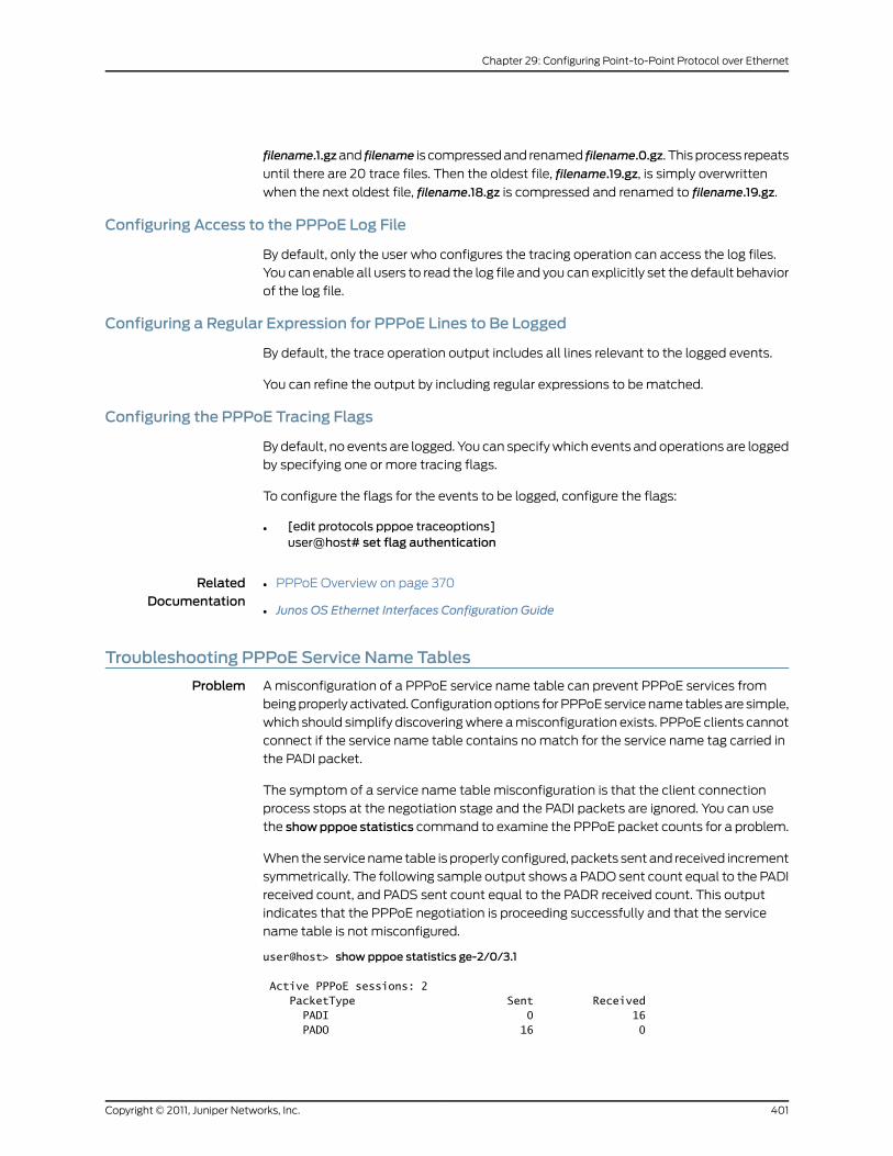
filename.1.gzand filename is compressed and renamed filename.0.gz. This process repeats
until there are 20 trace files. Then the oldest file, filename.19.gz, is simply overwritten
when the next oldest file, filename.18.gz is compressed and renamed to filename.19.gz.
Configuring Access to the PPPoE Log File
By default, only the user who configures the tracing operation can access the log files.
You can enable all users to read the log file and you can explicitly set the default behavior
of the log file.
Configuring a Regular Expression for PPPoE Lines to Be Logged
By default, the trace operation output includes all lines relevant to the logged events.
You can refine the output by including regular expressions to be matched.
Configuring the PPPoE Tracing Flags
By default, no events are logged. You can specify which events and operations are logged
by specifying one or more tracing flags.
To configure the flags for the events to be logged, configure the flags:
• [edit protocols pppoe traceoptions]user@host# set flag authentication
RelatedDocumentation
PPPoE Overview on page 370•
• Junos OS Ethernet Interfaces Configuration Guide
Troubleshooting PPPoE Service Name Tables
Problem A misconfiguration of a PPPoE service name table can prevent PPPoE services from
being properly activated. Configuration options for PPPoE service name tables are simple,
which should simplify discovering where a misconfiguration exists. PPPoE clients cannot
connect if the service name table contains no match for the service name tag carried in
the PADI packet.
The symptom of a service name table misconfiguration is that the client connection
process stops at the negotiation stage and the PADI packets are ignored. You can use
the showpppoe statistics command to examine the PPPoE packet counts for a problem.
When the service name table is properly configured, packets sent and received increment
symmetrically. The following sample output shows a PADO sent count equal to the PADI
received count, and PADS sent count equal to the PADR received count. This output
indicates that the PPPoE negotiation is proceeding successfully and that the service
name table is not misconfigured.
user@host> show pppoe statistics ge-2/0/3.1
Active PPPoE sessions: 2 PacketType Sent Received PADI 0 16 PADO 16 0
401Copyright © 2011, Juniper Networks, Inc.
Chapter 29: Configuring Point-to-Point Protocol over Ethernet

PADR 0 16 PADS 16 0 PADT 0 0 Service name error 0 0 AC system error 0 0 Generic error 0 0 Malformed packets 0 0 Unknown packets 0 0
When the service name table is misconfigured, the output of the show pppoe statistics
command indicates that the number of PADI packets received on the underlying interface
is increasing, but the number of PADO packets sent remains at zero. The following sample
output shows a PADI count of 100 and a PADO count of 0.
user@host> show pppoe statistics ge-2/0/3.1
Active PPPoE sessions: 0 PacketType Sent Received PADI 0 100 PADO 0 0 PADR 0 0 PADS 0 0 PADT 0 0 Service name error 0 0 AC system error 0 0 Generic error 0 0 Malformed packets 0 0 Unknown packets 0 0
When you believe a misconfiguration exists, use the monitor traffic interface command
on the underlying interface to determine which service name is being requested by the
PPPoE client. The following sample output shows that the client is requesting Service1
in the service name tag.
user@host> monitor traffic interface ge-2/0/3.1 print-hex print-ascii Listening on ge-2/0/3.1, capture size 96 bytes
11:49:41.436682 In PPPoE PADI [Service-Name "Service1"] [Host-Uniq UTF8] [TAG-0x120 UTF8] [Vendor-Specific UTF8] 0x0000 ffff ffff ffff 0090 1a42 0ac1 8100 029a .........B...... 0x0010 8863 1109 0000 00c9 0101 0008 5365 7276 .c..........Serv 0x0020 6963 6531 0103 0004 1200 9c43 0120 0002 ice1.......C.... 0x0030 044a 0105 00ab 0000 0de9 0124 783a 3132 .J.........$x:12 0x0040 3030 3963 009c
You can then use the show pppoe service-name-tables command to determine whether
you have misspelled the name of the service or perhaps not configured the service at all.
Cause Typical misconfigurations appear in the service name table configurations.
Solution Use the appropriate statements to correct the misconfiguration.
RelatedDocumentation
Configuring PPPoE Service Name Tables on page 388•
• show pppoe service-name-tables
• show pppoe statistics
Copyright © 2011, Juniper Networks, Inc.402
Junos®
OS 11.4 Ethernet Interfaces Configuration Guide

• show pppoe underlying-interfaces
• PPPoE Overview on page 370
• Junos OS Ethernet Interfaces Configuration Guide
Verifying a PPPoE Configuration
Purpose You can use show commands to display and verify the PPPoE configuration.
Action To verify a PPPoE configuration, you can issue the following operational mode commands:
• show interfaces at-fpc/pic/port extensive
• show interfaces pp0
• show pppoe interfaces
• show pppoe version
• show pppoe service-name-tables
• show pppoe sessions
• show pppoe statistics
• show pppoe underlying-interfaces
For more information about these operational mode commands, see the Junos OS
Administration Guide for Security Devices and the Junos OS Interfaces Command Reference.
RelatedDocumentation
• PPPoE Overview on page 370
• Junos OS Ethernet Interfaces Configuration Guide
403Copyright © 2011, Juniper Networks, Inc.
Chapter 29: Configuring Point-to-Point Protocol over Ethernet

Copyright © 2011, Juniper Networks, Inc.404
Junos®
OS 11.4 Ethernet Interfaces Configuration Guide
CHAPTER 30
ConfiguringEthernetAutomaticProtectionSwitching
• Ethernet Automatic Protection Switching Overview on page 405
• Mapping of CCM Defects to APS Events on page 408
• Example: Configuring Protection Switching Between Psuedo Wires on page 409
Ethernet Automatic Protection Switching Overview
Ethernet automatic protection switching (APS) is a linear protection scheme designed
to protect VLAN based Ethernet networks.
With Ethernet APS, a protected domain is configured with two paths, a working path and
a protection path. Both working and protection paths can be monitored using an
Operations Administration Management (OAM) protocol like Connectivity Fault
Management (CFM). Normally, traffic is carried on the working path (that is, the working
path is the active path), and the protection path is disabled. If the working path fails, APS
switches the traffic to the protection path, and the protection path becomes the active
path.
APS uses two modes of operation, linear 1+1 protection switching architecture and linear
1:1 protection switching architecture. The linear 1+1 protection switching architecture
operates with either unidirectional or bidirectional switching. The linear 1:1 protection
switching architecture operates with bidirectional switching.
In the linear 1+1 protection switching architecture, the normal traffic is copied and fed to
both working and protection paths with a permanent bridge at the source of the protected
domain. The traffic on the working and protection transport entities is transmitted
simultaneously to the sink of the protected domain, where a selection between the
working and protection transport entities is made.
In the linear 1:1 protection switching architecture, the normal traffic is transported on
either the working path or on the protection path using a selector bridge at the source of
the protection domain. The selector at the sink of the protected domain selects the entity
that carries the normal traffic.
405Copyright © 2011, Juniper Networks, Inc.

Unidirectional and Bidirectional Switching
Unidirectional switching utilizes fully independent selectors at each end of the protected
domain. Bidirectional switching attempts to configure the two end points with the same
bridge and selector settings, even for a unidirectional failure. Unidirectional switching
can protect two unidirectional failures in opposite directions on different entities.
Selective andMerging Selectors
In the linear 1:1 protection switching architecture, where traffic is sent only on the active
path, there are two different ways in which the egress direction (the direction out of the
protected segment) data forwarding can act: selective selectors and merging selectors.
A selective selector forwards only traffic that is received from both the paths regardless
of which one is currently active. In other words, with a merging selector the selection of
the currently active path only affects the ingress direction. Merging selectors minimize
the traffic loss during a protection switch, but they do not guarantee the delivery of the
data packets in order.
Revertive and Nonrevertive Switching
For revertive switching, traffic is restored to the working path after the conditions causing
the switch have cleared.
For nonrevertive switching, traffic is allowed to remain on the protection path even after
the conditions causing the switch have cleared.
NOTE: The configuration on both the provider edge (PE) routers have to beeither in revertive mode or non-revertive mode.
Protection Switching Between VPWSPseudowires
Figure 28: Connections Terminating on Single PE
CE1 PE2PE1 CE2
MPLS CoreAttachment
circuitAttachment
circuit
Customer site A Customer site B
Working LSPProtection LSP
g017
516
G.8031
In the scenario diagramed in Figure 28 on page 406, a Virtual Private Wire Service (VPWS)
is provisioned between customer sites A and B using a single pseudowire (layer 2 circuit)
in the core network, and two Multiprotocol Label Switching (MPLS) Label Switched
Paths (LSPs) are provisioned, one for the working path and the other one for the protection
Copyright © 2011, Juniper Networks, Inc.406
Junos®
OS 11.4 Ethernet Interfaces Configuration Guide
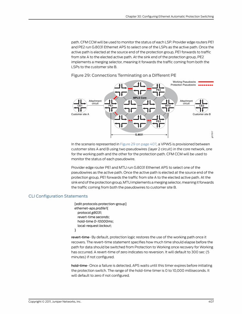
path. CFM CCM will be used to monitor the status of each LSP. Provider edge routers PE1
and PE2 run G.8031 Ethernet APS to select one of the LSPs as the active path. Once the
active path is elected at the source end of the protection group, PE1 forwards to traffic
from site A to the elected active path. At the sink end of the protection group, PE2
implements a merging selector, meaning it forwards the traffic coming from both the
LSPs to the customer site B.
Figure 29: Connections Terminating on a Different PE
CE1 MTUPE1 CE2
MPLS CoreAttachment
circuitAttachment
circuit
Customer site A Customer site B
Working PseudowireProtection Pseudowire
g017
517
G.8031
PE3
PE2
In the scenario represented in Figure 29 on page 407, a VPWS is provisioned between
customer sites A and B using two pseudowires (layer 2 circuit) in the core network, one
for the working path and the other for the protection path. CFM CCM will be used to
monitor the status of each pseudowire.
Provider edge router PE1 and MTU run G.8031 Ethernet APS to select one of the
pseudowires as the active path. Once the active path is elected at the source end of the
protection group, PE1 forwards the traffic from site A to the elected active path. At the
sink end of the protection group, MTU implements a merging selector, meaning it forwards
the traffic coming from both the pseudowires to customer site B.
CLI Configuration Statements
[edit protocols protection-group]ethernet-aps profile1{protocol g8031;revert-time seconds;hold-time 0-10000ms;local-request lockout;
}
revert-time- By default, protection logic restores the use of the working path once it
recovers. The revert-time statement specifies how much time should elapse before the
path for data should be switched from Protection to Working once recovery for Working
has occurred. A revert-time of zero indicates no reversion. It will default to 300 sec (5
minutes) if not configured.
hold-time- Once a failure is detected, APS waits until this timer expires before initiating
the protection switch. The range of the hold-time timer is 0 to 10,000 milliseconds. It
will default to zero if not configured.
407Copyright © 2011, Juniper Networks, Inc.
Chapter 30: Configuring Ethernet Automatic Protection Switching

local-request- Configuring this value to lockout or force-switch will trigger lockout or
force-switch operation on the protection groups using this profile.
RelatedDocumentation
Mapping of CCM Defects to APS Events on page 408•
• Example: Configuring Protection Switching Between Psuedo Wires on page 409
Mapping of CCMDefects to APS Events
The continuity check message (CCM) engine marks the status of working and protected
transport entities as either Down, Degraded, or Up.
Down—The monitored path is declared down if any of the following Multiple End Point
(MEP) defects occur:
• Interface down
• CCM expiry
• RDI indicating signal failure
Degraded—The monitored path is declared degraded if any of the following MEP defects
occur:
• FRR on
• FRR-ACK on
Up—The monitored path is declared up in the absence of any of the above events.
Figure 30: Understanding APS Events
APSEvent
Generator
Up
Down
Degraded
Up
Down
Degraded
g017
520
Protection
Working
As show in Figure 30 on page 408, the APS event generator generates the following APS
events based on the status of the working and protection paths:
• SF—Signal failure on working path
• RSF—Working path recovers from signal failure
• SF-P—Signal failure on protection path
• RSF-P—Protection path recovers from signal failure
Copyright © 2011, Juniper Networks, Inc.408
Junos®
OS 11.4 Ethernet Interfaces Configuration Guide

RelatedDocumentation
Ethernet Automatic Protection Switching Overview on page 405•
• Example: Configuring Protection Switching Between Psuedo Wires on page 409
Example: Configuring Protection Switching Between PsuedoWires
• Requirements on page 409
• Overview and Topology on page 409
• Configuration on page 409
Requirements
This example uses the following hardware and software components:
• Junos OS Release 11.2 or later
• 2 MX Series PE routers
Overview and Topology
The physical topology of the protection switching between psuedo wires example is
shown in Figure 31 on page 409.
Figure 31: Topology of a Network Using VPWSPsuedoWires
CE1 PE2PE1 CE2
MPLS CoreAttachment
circuitAttachment
circuit
Customer site A Customer site B
Working LSPProtection LSP
g017
516
G.8031
The following definitions describe the meaning of the device abbreviations used in Figure
31 on page 409.
• Customer edge (CE) device—A device at the customer site that provides access to the
service provider’s VPN over a data link to one or more provider edge (PE) routers.
• Provider edge (PE) device—A device, or set of devices, at the edge of the provider
network that presents the provider's view of the customer site.
Configuration
Step-by-StepProcedure
To configure protection switching between psuedo wires, perform these tasks:
Configure automatic protection switching.1.
409Copyright © 2011, Juniper Networks, Inc.
Chapter 30: Configuring Ethernet Automatic Protection Switching

protocols {protection-group {ethernet-aps {profile-1 {protocol g8031;hold-time 1000s;revert-time 5m;
}}
}
2. Configure the connectivity fault management.
ethernet {oam {connectivity-fault-management {maintenance-domainmd1 {level 5;
3. Configure the continuity check message for the working path.
maintenance-associationW {protect maintenance-association P {aps-profile profile-1;
}continuity-check {interval 1s;
}mep 100 {interface ge-1/0/0.0 working;direction down;auto-discovery;
}}
4. Configure the continuity check message for the protection path.
maintenance-association P {continuity-check {interval 1s;
}mep 100 {interface ge-1/0/0.0 protect;direction down;auto-discovery;
}}
Results Check the results of the configuration:
protocols {protection-group {ethernet-aps {profile-1 {protocol g8031;hold-time 1000s;revert-time 5m;
}
Copyright © 2011, Juniper Networks, Inc.410
Junos®
OS 11.4 Ethernet Interfaces Configuration Guide
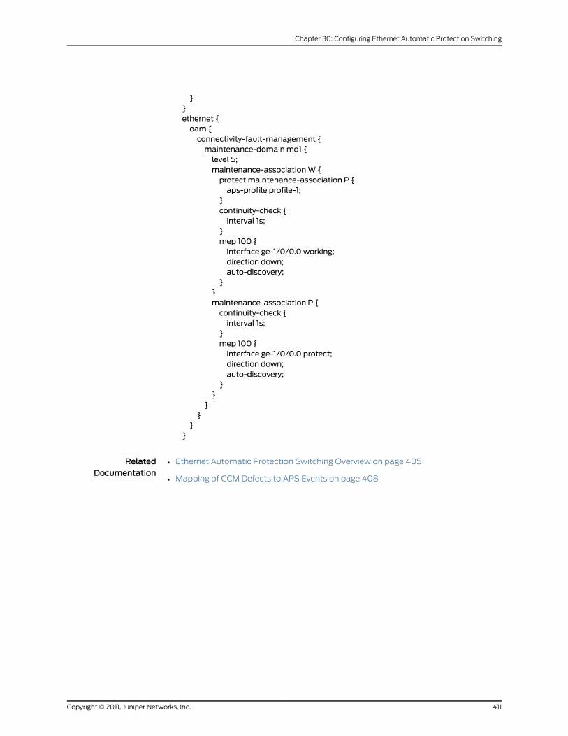
}}ethernet {oam {connectivity-fault-management {maintenance-domainmd1 {level 5;maintenance-associationW {protect maintenance-association P {aps-profile profile-1;
}continuity-check {interval 1s;
}mep 100 {interface ge-1/0/0.0 working;direction down;auto-discovery;
}}maintenance-association P {continuity-check {interval 1s;
}mep 100 {interface ge-1/0/0.0 protect;direction down;auto-discovery;
}}
}}
}}
RelatedDocumentation
• Ethernet Automatic Protection Switching Overview on page 405
• Mapping of CCM Defects to APS Events on page 408
411Copyright © 2011, Juniper Networks, Inc.
Chapter 30: Configuring Ethernet Automatic Protection Switching

Copyright © 2011, Juniper Networks, Inc.412
Junos®
OS 11.4 Ethernet Interfaces Configuration Guide
CHAPTER 31
Configuring Ethernet Ring ProtectionSwitching
• Ethernet Ring Protection Switching Overview on page 413
• Understanding Ethernet Ring Protection Switching Functionality on page 414
• Configuring Ethernet Ring Protection Switching on page 418
• Example: Ethernet Ring Protection Switching Configuration on page 419
Ethernet Ring Protection Switching Overview
MX Series routers support Ethernet ring protection switching, which helps achieve high
reliability and network stability. Links in the ring will never form loops that fatally affect
the network operation and services availability. The basic idea of an Ethernet ring is to
use one specific link to protect the whole ring. This special link is called a ring protection
link (RPL). If no failure happens in other links of the ring, the RPL blocks the traffic and is
not used. RPL is controlled by a special node called an RPL owner. There is only one RPL
owner in a ring. The RPL owner is responsible for blocking traffic over the RPL. Under ring
failure conditions, the RPL owner is responsible for unblocking traffic over the RPL. A ring
failure results in protection switching of the RPL traffic. An APS protocol is used to
coordinate the protection actions over the ring. Protection switching blocks traffic on the
failed link and unblocks the traffic on the RPL. When the failure clears, revertive protection
switching blocks traffic over the RPL and unblocks traffic on the link on which the failure
is cleared.
The following standards provide detailed information on Ethernet ring protection
switching:
• IEEE 802.1Q - 1998
• IEEE 802.1D - 2004
• IEEE 802.1Q - 2003
• Draft ITU-T Recommendation G.8032/Y.1344, Ethernet Ring protection switching
• ITU-T Y.1731, OAM functions and mechanisms for Ethernet-based networks
For additional information on configuring Ethernet ring protection switching on MX Series
routers, see the Layer 2 Configuration Guide for a complete example of Ethernet rings and
information about STP loop avoidance and prevention.
413Copyright © 2011, Juniper Networks, Inc.
RelatedDocumentation
Understanding Ethernet Ring Protection Switching Functionality on page 414•
• Configuring Ethernet Ring Protection Switching on page 418
• Example: Ethernet Ring Protection Switching Configuration on page 419
• Junos OS Ethernet Interfaces Configuration Guide
Understanding Ethernet Ring Protection Switching Functionality
• Acronyms on page 414
• Ring Nodes on page 415
• Ring Node States on page 415
• Failure Detection on page 415
• Logical Ring on page 415
• FDB Flush on page 415
• Traffic Blocking and Forwarding on page 416
• RAPS Message Blocking and Forwarding on page 416
• Dedicated Signaling Control Channel on page 417
• RAPS Message Termination on page 417
• Manual Switch on page 417
• Nonrevertive Switch on page 417
• Multiple Rings on page 417
• Node ID on page 417
• Bridge Domains with the Ring Port on page 418
Acronyms
The following acronyms are used in this section:
• MA—Maintenance association
• MEP—Maintenance association end point
• OAM—Connectivity fault management daemon
• FDB—MAC forwarding database
• STP—Spanning Tree Protocol
• RAPS—Ring automatic protection switching
• WTR—Wait to restore
• RPL—Ring protection link
Copyright © 2011, Juniper Networks, Inc.414
Junos®
OS 11.4 Ethernet Interfaces Configuration Guide
Ring Nodes
Multiple nodes are used to form a ring. For each ring node. There are two different node
types:
• Normal node—The node has no special role on the ring.
• RPL owner node—The node owns the RPL and blocks or unblocks traffic over the RPL.
This node also initiates the RAPS message.
Ring Node States
There are three different states for each node of a specific ring:
• init—Not a participant of a specific ring.
• idle—No failure on the ring, the node is performing normally. For normal node, traffic
is unblocked on both ring ports. For the RPL owner, traffic is blocked on the ring port
that connects to the RPL and unblocked on the other ring port.
• protection—A failure occurred on the ring. For normal node, traffic is blocked on the
ring port that connects to the failing link and unblocked on working ring ports. For the
RPL owner, traffic is unblocked on both ring ports if they connect to non-failure links.
There can be only one RPL owner for each ring. The user configuration must guarantee
this, because the APS protocol cannot check this.
Failure Detection
Ethernet ring operation depends on quick and accurate failure detection. The failure
condition signal failure (SF) is supported. For SF detection, an Ethernet continuity check
MEP must be configured for each ring link. For fast protection switching, a 10-ms
transmission period for this MEP group is supported. OAM monitors the MEP group's MA
and reports SF or SF clear events to the Ethernet ring control module. For this MEP group,
the action profile must be configured to update the interface device IFF_LINKDOWN flag.
OAM updates the IFF_LINKDOWN flag to notify the Ethernet ring control module.
Logical Ring
This feature currently supports only the physical ring, which means that two adjacent
nodes of a ring must be physically connected and the ring must operate on the physical
interface, not the VLAN.
FDB Flush
When ring protection switching occurs, normally an FDB flush should be executed. The
Ethernet ring control module should use the same mechanism as the STP to trigger the
FDB flush. The Ethernet ring control module controls the ring port physical interface's
default STP index to execute the FDB flush.
415Copyright © 2011, Juniper Networks, Inc.
Chapter 31: Configuring Ethernet Ring Protection Switching

Traffic Blocking and Forwarding
The Ethernet ring control module uses the same mechanism as the STP to control
forwarding or discarding of user traffic. The Ethernet ring control module sets the ring
port physical interface default STP index state to forwarding or discarding in order to
control user traffic.
RAPSMessage Blocking and Forwarding
The router treats the ring automatic protection switching (RAPS) message the same as
user traffic for forwarding RAPS messages between two ring ports. The ring port physical
interface default STP index state also controls forwarding RAPS messages between the
two ring ports. Other than forwarding RAPS between the two ring ports, as shown in
Figure 32 on page 416, the system also needs to forward the RAPS message between the
CPU (Ethernet ring control module) and the ring port. This type of forwarding does not
depend on the ring port physical interfaces STP index state. The RAPS message is always
sent by the router through the ring ports, as shown in Figure 33 on page 416. A RAPS
message received from a discarding ring port is sent to the Ethernet ring control module,
but is not sent to the other ring port.
Figure 32: Protocol Packets from the Network to the Router
Incoming ring port, R_APS multicast MAC address(01-19-a7-00-00-01)
other ring port(STP index state applies on this port and the incoming ring port)
CPU (Ethernet ring module)(STP index state does not apply on the incoming ring port)
g017
271
Figure 33: Protocol Packets from the Router to the Network
CPU, R_APS multicast MAC address(01-19-a7-00-00-01)
east ring port (STP index state does not apply)
west ring port (STP index state does not apply) g017
270
Juniper Networks routers use an implicit filter to achieve these routes. Each implicit filter
binds to a bridge domain. Therefore, the east ring port control channel and the west ring
port control channel of a particular ring instance must be configured to the same bridge
domain. For each ring port control channel, a filter term is generated to control RAPS
message forwarding. The filter number is the same as the number of bridge domains
that contain the ring control channels. If a bridge domain contains control channels from
multiple rings, the filter related to this bridge domain will have multiple terms and each
term will relate to a control channel. The filter has command parts and control-channel
related parts, as follows:
• Common terms:
• term 1: if [Ethernet type is not OAM Ethernet type (0x8902)] { accept packet }
• term 2: if [source MAC address belongs to this bridge]{ drop packet, our packet loop through the ring and come backto home}
Copyright © 2011, Juniper Networks, Inc.416
Junos®
OS 11.4 Ethernet Interfaces Configuration Guide

• term 3: if [destination is the RAPS PDUmulticast address(0x01,0x19,0xa7,0x00,0x00,0x01] AND[ring port STP status is DISCARDING]
{ send to CPU }
• Control channel related terms:
• if [destination is the RAPS PDUmulticast address(0x01,0x19,0xa7,0x00,0x00,0x01] AND[ring port STP status is FORWARDING] AND [Incoming interfaceIFL equal to control channel IFL]{ send packet to CPU and send to the other ring port }default term: accept packet.
Dedicated Signaling Control Channel
For each ring port, a dedicated signaling control channel with a dedicated VLAN ID must
be configured. In Ethernet ring configuration, only this control logical interface is configured
and the underlying physical interface is the physical ring port. Each ring requires that two
control physical interfaces be configured. These two logical interfaces must be configured
in a bridge domain in order to forward RAPS PDUs between the two ring control physical
interfaces. If the control channel logical interface is not a trunk port, only control logical
interfaces will be configured in ring port configuration. If this control channel logical
interface is a trunk port, in addition to the control channel logical interfaces, a dedicated
VLAN ID must be configured.
RAPSMessage Termination
The RAPS message starts from the originating node, travels through the entire ring, and
terminates in the originating node unless a failure is present in the ring. The originating
node must drop the RAPS message if the source MAC address in the RAPS message
belongs to itself. The source MAC address is the node's node ID.
Manual Switch
Manual switch is not supported in this release.
Nonrevertive Switch
In revertive operation, once the condition causing a switch has cleared, traffic is blocked
on the RPL and restored to the working transport entity. In nonrevertive operation, traffic
is allowed to use the RPL if it has not failed, even after a switch condition has cleared.
Nonrevertive switching is not supported in this release.
Multiple Rings
The Ethernet ring control module supports multiple rings in each node, (two logical
interfaces are part of each ring). However, interconnection of multiple rings is not
supported in this release. The interconnection of two rings means that two rings may
share the same link or share the same node.
Node ID
For each node in the ring, a unique node ID identifies each node. The node ID is the node's
MAC address. You can configure this node ID when configuring the ring on the node or
automatically select an ID such as STP. In most cases, you will not configure this and the
417Copyright © 2011, Juniper Networks, Inc.
Chapter 31: Configuring Ethernet Ring Protection Switching
router will select a node ID, like STP does. It should be the manufacturing MAC address.
The ring node ID should not be changed, even if you change the manufacturing MAC
address. Any MAC address can be used if you make sure each node in the ring has a
different node ID.
Bridge Domains with the Ring Port
From the router point of view, the protection group is seen as an abstract logical port
that can be configured to any bridge domain. Therefore, if you configure one ring port or
its logical interface in a bridge domain; you must configure the other related ring port or
its logical interface to the same bridge domain. The bridge domain that includes the ring
port acts as any other bridge domain and supports the IRB layer 3 interface.
RelatedDocumentation
Ethernet Ring Protection Switching Overview on page 413•
• Configuring Ethernet Ring Protection Switching on page 418
• Example: Ethernet Ring Protection Switching Configuration on page 419
• Junos OS Ethernet Interfaces Configuration Guide
Configuring Ethernet Ring Protection Switching
The inheritance model follows:
protection-group {ethernet-ring ring-name (node-idmac-address;ring-protection-link-owner;east-interface {control-channel channel-name {ring-protection-link-end;
}west-interface {node-idmac-address;control-channel channel-name {ring-protection-link-end;
}data-channel {vlan number;
}guard-interval number;restore-interval number;
}}
For each ring, a protection group must be configured. There may be several rings in each
node, so there should be multiple protection groups corresponding to the related Ethernet
rings.
Three interval parameters (restore-interval, guard-interval, and hold-interval) can be
configured at the protection group level. These configurations are global configurations
and apply to all Ethernet rings if the Ethernet ring doesn't have a more specific
Copyright © 2011, Juniper Networks, Inc.418
Junos®
OS 11.4 Ethernet Interfaces Configuration Guide
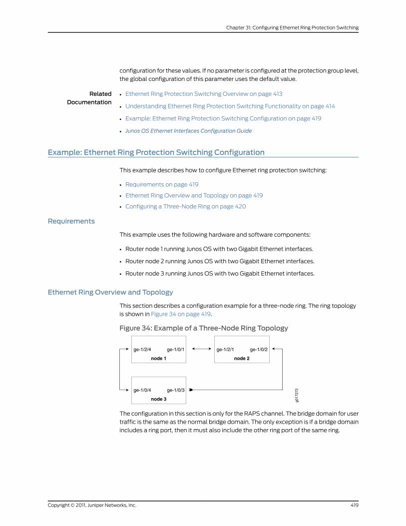
configuration for these values. If no parameter is configured at the protection group level,
the global configuration of this parameter uses the default value.
RelatedDocumentation
Ethernet Ring Protection Switching Overview on page 413•
• Understanding Ethernet Ring Protection Switching Functionality on page 414
• Example: Ethernet Ring Protection Switching Configuration on page 419
• Junos OS Ethernet Interfaces Configuration Guide
Example: Ethernet Ring Protection Switching Configuration
This example describes how to configure Ethernet ring protection switching:
• Requirements on page 419
• Ethernet Ring Overview and Topology on page 419
• Configuring a Three-Node Ring on page 420
Requirements
This example uses the following hardware and software components:
• Router node 1 running Junos OS with two Gigabit Ethernet interfaces.
• Router node 2 running Junos OS with two Gigabit Ethernet interfaces.
• Router node 3 running Junos OS with two Gigabit Ethernet interfaces.
Ethernet Ring Overview and Topology
This section describes a configuration example for a three-node ring. The ring topology
is shown in Figure 34 on page 419.
Figure 34: Example of a Three-Node Ring Topology
g017
272
ge-1/2/4 ge-1/0/1
node 1
ge-1/2/1 ge-1/0/2
node 2
ge-1/0/4 ge-1/0/3
node 3
The configuration in this section is only for the RAPS channel. The bridge domain for user
traffic is the same as the normal bridge domain. The only exception is if a bridge domain
includes a ring port, then it must also include the other ring port of the same ring.
419Copyright © 2011, Juniper Networks, Inc.
Chapter 31: Configuring Ethernet Ring Protection Switching

Configuring a Three-Node Ring
To configure Ethernet Ring Protection Switching on a three-node ring, perform these
tasks:
• Configuring Ethernet Ring Protection Switching on a Three-Node Ring on page 420
Configuring Ethernet Ring Protection Switching on a Three-Node Ring
Step-by-StepProcedure
Configuring Node 1
interfaces {ge-1/0/1 {
1.
vlan-tagging;encapsulation flexible-ethernet-services;unit 1 {encapsulation vlan-bridge;vlan-id 100;
}}ge-1/2/4 {vlan-tagging;encapsulation flexible-ethernet-services;unit 1 {encapsulation vlan-bridge;vlan-id 100;}
}}bridge-domains {bd1 {domain-type bridge;interface ge-1/2/4.1;interface ge-1/0/1.1;}
}protocols {protection-group {ethernet-ring pg101 {node-id 00:01:01:00:00:01;ring-protection-link-owner;east-interface {control-channel ge-1/0/1.1;ring-protection-link-end;}
west-interface {control-channel ge-1/2/4.1;}
}}
}protocols {oam {ethernet {connectivity-fault-management {action-profile rmep-defaults {
Copyright © 2011, Juniper Networks, Inc.420
Junos®
OS 11.4 Ethernet Interfaces Configuration Guide

default-action {interface-down;}
}maintenance-domain d1 {level 0;maintenance-association 100 {mep 1 {interface ge-1/0/1;remote-mep 2 {action-profile rmep-defaults;}
}}
}maintenance-domain d2 {level 0;maintenance-association 100 {mep 1 {interface ge-1/2/4;remote-mep 2 {action-profile rmep-defaults;}
}}
}}
}}
}}
2. Configuring Node 2
interfaces {ge-1/0/2 {vlan-tagging;encapsulation flexible-ethernet-services;unit 1 {encapsulation vlan-bridge;vlan-id 100;
}}
ge-1/2/1 {vlan-tagging;encapsulation flexible-ethernet-services;unit 1 {encapsulation vlan-bridge;vlan-id 100;
}}
}
bridge-domains {bd1 {domain-type bridge;
421Copyright © 2011, Juniper Networks, Inc.
Chapter 31: Configuring Ethernet Ring Protection Switching

interface ge-1/2/1.1;interface ge-1/0/2.1;
}}
protocols {protection-group {ethernet-ring pg102 {east-interface {control-channel ge-1/0/2.1;
}west-interface {control-channel ge-1/2/1.1;
}}
}}
protocols {oam {ethernet {connectivity-fault-management {action-profile rmep-defaults {default-action {interface-down;
}}maintenance-domain d1 {level 0;maintenance-association 100 {mep 2 {interface ge-1/2/1;remote-mep 1 {action-profile rmep-defaults;
}}
}}maintenance-domain d3 {level 0;maintenance-association 100 {mep 1 {interface ge-1/0/2;remote-mep 2 {action-profile rmep-defaults;
}}
}}
}}
}}
Copyright © 2011, Juniper Networks, Inc.422
Junos®
OS 11.4 Ethernet Interfaces Configuration Guide
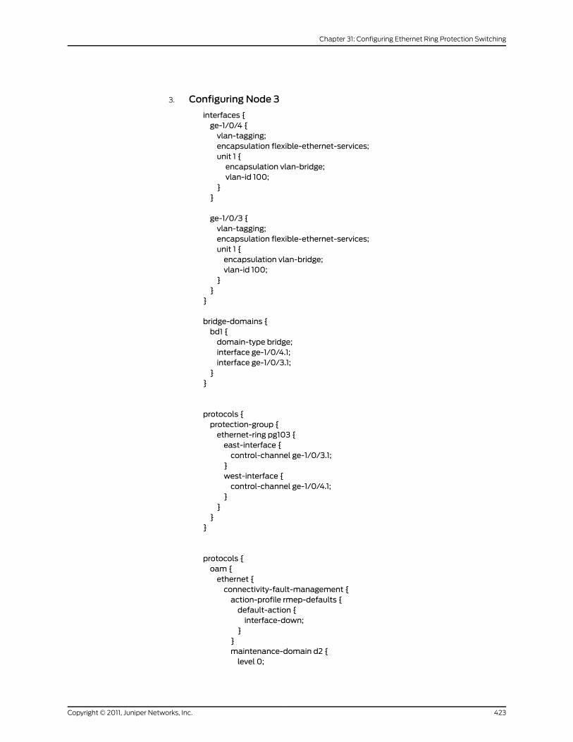
3. Configuring Node 3
interfaces {ge-1/0/4 {vlan-tagging;encapsulation flexible-ethernet-services;unit 1 {encapsulation vlan-bridge;vlan-id 100;
}}
ge-1/0/3 {vlan-tagging;encapsulation flexible-ethernet-services;unit 1 {encapsulation vlan-bridge;vlan-id 100;
}}
}
bridge-domains {bd1 {domain-type bridge;interface ge-1/0/4.1;interface ge-1/0/3.1;
}}
protocols {protection-group {ethernet-ring pg103 {east-interface {control-channel ge-1/0/3.1;
}west-interface {control-channel ge-1/0/4.1;
}}
}}
protocols {oam {ethernet {connectivity-fault-management {action-profile rmep-defaults {default-action {interface-down;
}}maintenance-domain d2 {level 0;
423Copyright © 2011, Juniper Networks, Inc.
Chapter 31: Configuring Ethernet Ring Protection Switching

maintenance-association 100 {mep 2 {interface ge-1/0/4;remote-mep 1 {action-profile rmep-defaults;
}}
}}maintenance-domain d3 {level 0;maintenance-association 100 {mep 2 {interface ge-1/0/3;remote-mep 1 {action-profile rmep-defaults;
}}
}}
}}
}}
Examples: EthernetRPSOutput
This section provides output examples based on the configuration shown in “Example:Ethernet Ring Protection Switching Configuration” on page 419. The show commandsused in these examples can help verify configuration and correct operation.
NormalSituation—RPLOwner Node
If the ring has no failure, the show command will have the following output for Node 1:
user@node1> show protection-group ethernet-ring aps
Ethernet Ring Name Request/state No Flush Ring Protection Link Blocked pg101 NR No Yes
Originator Remote Node IDYes
user@node1> show protection-group ethernet-ring interfaceEthernet ring port parameters for protection group pg101
Interface Control Channel Forward State Ring Protection Link End ge-1/0/1 ge-1/0/1.1 discarding Yes ge-1/2/4 ge-1/2/4.1 forwarding No
Signal Failure Admin StateClear IFF readyClear IFF ready
user@node1> show protection-group ethernet-ring node-stateEthernet ring APS State Event Ring Protection Link Owner pg101 idle NR-RB Yes
Restore Timer Quard Timer Operation statedisabled disabled operational
user@node1> show protection-group ethernet-ring statistics group-name pg101
Copyright © 2011, Juniper Networks, Inc.424
Junos®
OS 11.4 Ethernet Interfaces Configuration Guide

Ethernet Ring statistics for PG pg101RAPS sent : 1RAPS received : 0Local SF happened: : 0Remote SF happened: : 0NR event happened: : 0NR-RB event happened: : 1
NormalSituation—Other
Nodes
For Node 2 and Node 3, the outputs should be the same:
user@node2> show protection-group ethernet-ring apsEthernet Ring Name Request/state No Flush Ring Protection Link Blockedpg102 NR No Yes
Originator Remote Node IDNo 00:01:01:00:00:01
user@node2> show protection-group ethernet-ring interfaceEthernet ring port parameters for protection group pg102
Interface Control Channel Forward State Ring Protection Link End ge-1/2/1 ge-1/2/1.1 forwarding No ge-1/0/2 ge-1/0/2.1 forwarding No
Signal Failure Admin StateClear IFF readyClear IFF ready
user@node2> show protection-group ethernet-ring node-stateEthernet ring APS State Event Ring Protection Link Owner pg102 idle NR-RB No
Restore Timer Quard Timer Operation statedisabled disabled operational
user@node2> show protection-group ethernet-ring statistics group-name pg102Ethernet Ring statistics for PG pg101RAPS sent : 0RAPS received : 1Local SF happened: : 0Remote SF happened: : 0NR event happened: : 0NR-RB event happened: : 1
Failure Situation—RPLOwner Node
If the ring has a link failure between Node 2 and Node 3, the show command will have
the following outputs for Node 1:
user@node1> show protection-group ethernet-ring apsEthernet Ring Name Request/state No Flush Ring Protection Link Blocked pg101 SF NO No
Originator Remote Node IDNo 00:01:02:00:00:01
user@node1> show protection-group ethernet-ring interfaceEthernet ring port parameters for protection group pg101
Interface Control Channel Forward State Ring Protection Link End ge-1/0/1 ge-1/0/1.1 forwarding Yes ge-1/2/4 ge-1/2/4.1 forwarding No
Signal Failure Admin State
425Copyright © 2011, Juniper Networks, Inc.
Chapter 31: Configuring Ethernet Ring Protection Switching
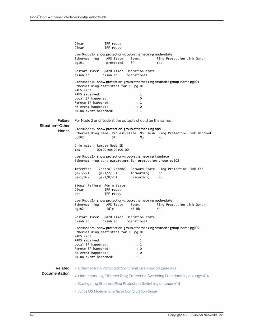
Clear IFF readyClear IFF ready
user@node1> show protection-group ethernet-ring node-stateEthernet ring APS State Event Ring Protection Link Ownerpg101 protected SF Yes
Restore Timer Quard Timer Operation statedisabled disabled operational
user@node1> show protection-group ethernet-ring statistics group-name pg101Ethernet Ring statistics for PG pg101RAPS sent : 1RAPS received : 1Local SF happened: : 0Remote SF happened: : 1NR event happened: : 0NR-RB event happened: : 1
FailureSituation—Other
Nodes
For Node 2 and Node 3, the outputs should be the same:
user@node2> show protection-group ethernet-ring apsEthernet Ring Name Request/state No Flush Ring Protection Link Blocked pg102 SF No No
Originator Remote Node IDYes 00:00:00:00:00:00
user@node2> show protection-group ethernet-ring interfaceEthernet ring port parameters for protection group pg102
Interface Control Channel Forward State Ring Protection Link End ge-1/2/1 ge-1/2/1.1 forwarding No ge-1/0/2 ge-1/0/2.1 discarding No
Signal Failure Admin StateClear IFF readyset IFF ready
user@node2> show protection-group ethernet-ring node-stateEthernet ring APS State Event Ring Protection Link Owner pg102 idle NR-RB No
Restore Timer Quard Timer Operation statedisabled disabled operational
user@node2> show protection-group ethernet-ring statistics group-name pg102Ethernet Ring statistics for PG pg101RAPS sent : 1RAPS received : 1Local SF happened: : 1Remote SF happened: : 0NR event happened: : 0NR-RB event happened: : 1
RelatedDocumentation
• Ethernet Ring Protection Switching Overview on page 413
• Understanding Ethernet Ring Protection Switching Functionality on page 414
• Configuring Ethernet Ring Protection Switching on page 418
• Junos OS Ethernet Interfaces Configuration Guide
Copyright © 2011, Juniper Networks, Inc.426
Junos®
OS 11.4 Ethernet Interfaces Configuration Guide
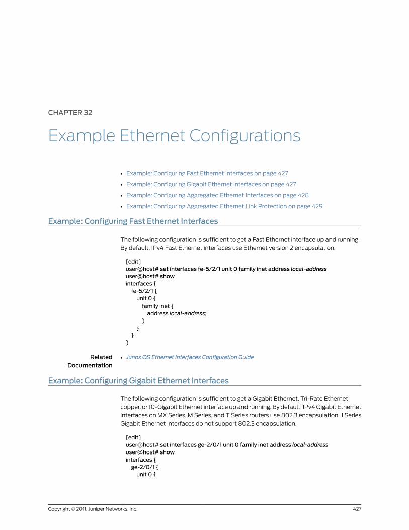
CHAPTER 32
Example Ethernet Configurations
• Example: Configuring Fast Ethernet Interfaces on page 427
• Example: Configuring Gigabit Ethernet Interfaces on page 427
• Example: Configuring Aggregated Ethernet Interfaces on page 428
• Example: Configuring Aggregated Ethernet Link Protection on page 429
Example: Configuring Fast Ethernet Interfaces
The following configuration is sufficient to get a Fast Ethernet interface up and running.
By default, IPv4 Fast Ethernet interfaces use Ethernet version 2 encapsulation.
[edit]user@host# set interfaces fe-5/2/1 unit 0 family inet address local-addressuser@host# showinterfaces {fe-5/2/1 {unit 0 {family inet {address local-address;
}}
}}
RelatedDocumentation
Junos OS Ethernet Interfaces Configuration Guide•
Example: Configuring Gigabit Ethernet Interfaces
The following configuration is sufficient to get a Gigabit Ethernet, Tri-Rate Ethernet
copper, or 10-Gigabit Ethernet interface up and running. By default, IPv4 Gigabit Ethernet
interfaces on MX Series, M Series, and T Series routers use 802.3 encapsulation. J Series
Gigabit Ethernet interfaces do not support 802.3 encapsulation.
[edit]user@host# set interfaces ge-2/0/1 unit 0 family inet address local-addressuser@host# showinterfaces {ge-2/0/1 {unit 0 {
427Copyright © 2011, Juniper Networks, Inc.

family inet {address local-address;
}}
}}
The M160, M320, M120, T320, and T640 2-port Gigabit Ethernet PIC supports two
independent Gigabit Ethernet links.
Each of the two interfaces on the PIC is named:
ge-fpc/pic/[0.1]
Each of these interfaces has functionality identical to the Gigabit Ethernet interface
supported on the single-port PIC.
RelatedDocumentation
Junos OS Ethernet Interfaces Configuration Guide•
Example: Configuring Aggregated Ethernet Interfaces
Aggregated Ethernet interfaces can use interfaces from different FPCs, DPCs, or PICs.
The following configuration is sufficient to get an aggregated Gigabit Ethernet interface
up and running.
[edit chassis]aggregated-devices {ethernet {device-count 15;
}}
[edit interfaces]ge-1/3/0 {gigether-options {802.3ad ae0;
}}ge-2/0/1 {gigether-options {802.3ad ae0;
}}ae0 {aggregated-ether-options {link-speed 1g;minimum-links 1;
}}vlan-tagging;unit 0 {vlan-id 1;family inet {address 14.0.100.50/24;
}
Copyright © 2011, Juniper Networks, Inc.428
Junos®
OS 11.4 Ethernet Interfaces Configuration Guide

}unit 1 {vlan-id 1024;family inet {address 14.0.101.50/24;
}}unit 2 {vlan-id 1025;family inet {address 14.0.102.50/24;
}}unit 3 {vlan-id 4094;family inet {address 14.0.103.50/24;
}}
}
RelatedDocumentation
Junos OS Ethernet Interfaces Configuration Guide•
Example: Configuring Aggregated Ethernet Link Protection
The following configuration enables link protection on the ae0 interface, and specifies
the ge-1/0/0 interface as the primary link and ge-1/0/1 as the secondary link.
[edit interfaces]ae0 {aggregated-ether-options {link protection;
}}[edit interfaces]ge-1/0/0 {gigether-options {802.3ad ae0 primary;
}}[edit interfaces]ge-1/0/1 {gigether-options {802.3ad ae0 backup;
}}
RelatedDocumentation
• Junos OS Ethernet Interfaces Configuration Guide
429Copyright © 2011, Juniper Networks, Inc.
Chapter 32: Example Ethernet Configurations

Copyright © 2011, Juniper Networks, Inc.430
Junos®
OS 11.4 Ethernet Interfaces Configuration Guide

PART 3
Ethernet Interface ConfigurationStatements
• Summary of Ethernet Interfaces Configuration Statements on page 433
431Copyright © 2011, Juniper Networks, Inc.

Copyright © 2011, Juniper Networks, Inc.432
Junos®
OS 11.4 Ethernet Interfaces Configuration Guide

CHAPTER 33
Summary of Ethernet InterfacesConfiguration Statements
The following descriptions explain each of the interface configuration statements. The
statements are organized alphabetically.
802.3ad
Syntax 802.3ad {aex (primary | backup);lacp {port-priority;
}}
Hierarchy Level [edit interfaces interface-name fastether-options],[edit interfaces interface-name gigether-options]
Release Information Statement introduced before Junos OS Release 7.4.
primary and backup options added in Junos OS Release 8.3.
Description Specify aggregated Ethernet logical interface number.
Options aex—Aggregated Ethernet logical interface number.
Range: 0 through 15
primary—For link protection configurations, specify the primary link for egress traffic.
backup—For link protection configurations, specify the backup link for egress traffic.
Required PrivilegeLevel
interface—To view this statement in the configuration.
interface-control—To add this statement to the configuration.
RelatedDocumentation
• Configuring an Aggregated Ethernet Interface on page 83
• Configuring Aggregated Ethernet Link Protection on page 107
433Copyright © 2011, Juniper Networks, Inc.

advertisement-interval
Syntax advertisement-interval seconds;
Hierarchy Level [edit protocols lldp],[edit routing-instances routing-instance-name protocols lldp]
Release Information Statement introduced in Junos OS Release 9.6.
Description (MX Series and T Series routers only) Configure an interval for LLDP advertisement.
Options seconds—Interval between LLDP advertisement.
Default: 30
Range: 5 through 32768
Required PrivilegeLevel
routing—To view this statement in the configuration.
routing-control—To add this statement to the configuration.
RelatedDocumentation
• Configuring LLDP on page 154
aggregate (Gigabit Ethernet CoS Policer)
Syntax aggregate {bandwidth-limit bps;burst-size-limit bytes;
}
Hierarchy Level [edit interfaces interface-name gigether-options ethernet-switch-profileethernet-policer-profile policer cos-policer-name]
Release Information Statement introduced before Junos OS Release 7.4.
Description Define a policer to apply to nonpremium traffic.
The statements are explained separately.
Required PrivilegeLevel
interface—To view this statement in the configuration.
interface-control—To add this statement to the configuration.
RelatedDocumentation
• Configuring Gigabit Ethernet Policers on page 313
• premium (Hierarchical Policer) on page 498
• ieee802.1p on page 455
Copyright © 2011, Juniper Networks, Inc.434
Junos®
OS 11.4 Ethernet Interfaces Configuration Guide
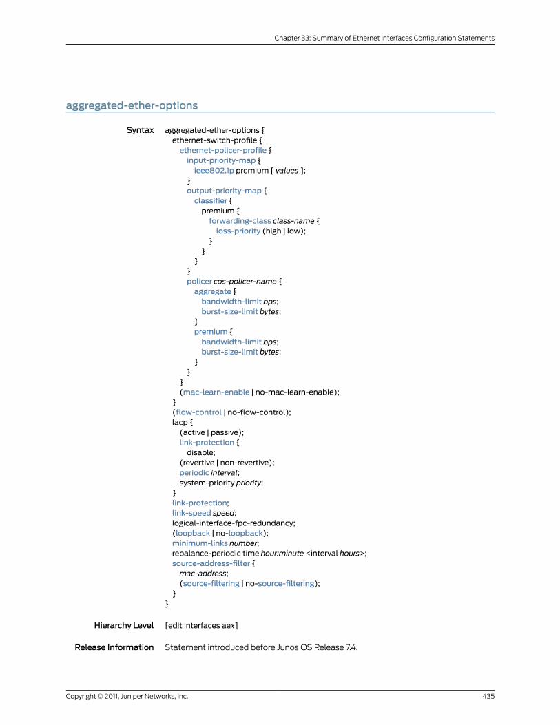
aggregated-ether-options
Syntax aggregated-ether-options {ethernet-switch-profile {ethernet-policer-profile {input-priority-map {ieee802.1p premium [ values ];
}output-priority-map {classifier {premium {forwarding-class class-name {loss-priority (high | low);
}}
}}policer cos-policer-name {aggregate {bandwidth-limit bps;burst-size-limit bytes;
}premium {bandwidth-limit bps;burst-size-limit bytes;
}}
}(mac-learn-enable | no-mac-learn-enable);
}(flow-control | no-flow-control);lacp {(active | passive);link-protection {disable;
(revertive | non-revertive);periodic interval;system-priority priority;
}link-protection;link-speed speed;logical-interface-fpc-redundancy;(loopback | no-loopback);minimum-links number;rebalance-periodic time hour:minute <interval hours>;source-address-filter {mac-address;(source-filtering | no-source-filtering);
}}
Hierarchy Level [edit interfaces aex]
Release Information Statement introduced before Junos OS Release 7.4.
435Copyright © 2011, Juniper Networks, Inc.
Chapter 33: Summary of Ethernet Interfaces Configuration Statements

Description Configure aggregated Ethernet-specific interface properties.
The statements are explained separately.
Required PrivilegeLevel
interface—To view this statement in the configuration.
interface-control—To add this statement to the configuration.
RelatedDocumentation
• Ethernet Interfaces Overview on page 35
Copyright © 2011, Juniper Networks, Inc.436
Junos®
OS 11.4 Ethernet Interfaces Configuration Guide

auto-negotiation
Syntax (auto-negotiation | no-auto-negotiation) <remote-fault (local-interface-online |local-interface-offline)>;
Hierarchy Level [edit interfaces interface-name ether-options],[edit interfaces interface-name gigether-options],[edit interfaces ge-pim/0/0 switch-options switch-port port-number]
Release Information Statement introduced in Junos OS Release 7.6.
Statement introduced in Junos OS Release 8.4 for J Series Services Routers.
Statement introduced in Junos OS Release 9.0 for EX Series switches.
Description For Gigabit Ethernet interfaces on M Series, MX Series, T Series, and TX Matrix routers,
explicitly enable autonegotiation and remote fault. For EX Series switches and J Series
Services Routers, explicitly enable autonegotiation only.
• auto-negotiation—Enables autonegotiation. This is the default.
• no-auto-negotiation—Disable autonegotiation. When autonegotiation is disabled, you
must explicitly configure the link mode and speed.
When you configure Tri-Rate Ethernet copper interfaces to operate at 1 Gbps,
autonegotiation must be enabled.
NOTE: On EX Series switches, an interface configuration that disablesautonegotiationandmanually sets the link speed to 1Gbps is acceptedwhenyou commit the configuration; however, if the interface you are configuringis a Tri-Rate Ethernet copper interface, the configuration is ignored as invalidand autonegotiation is enabled by default.
To correct the invalid configuration and disable autonegotiation:
1. Delete the no-auto-negotiation statement and commit the configuration.
2. Set the link speed to 10 or 100Mbps, set no-auto-negotiation, and commit
the configuration.
On J Series Services Routers with universal Physical Interface Modules (uPIMs) and on
EX Series switches, if the link speed and duplex mode are also configured, the interfaces
use the values configured as the desired values in the negotiation. If autonegotiation is
disabled, the link speed and link mode must be configured.
Default Autonegotiation is automatically enabled. No explicit action is taken after the
autonegotiation is complete or if the negotiation fails.
437Copyright © 2011, Juniper Networks, Inc.
Chapter 33: Summary of Ethernet Interfaces Configuration Statements

Options remote-fault (local-interface-online | local-interface-offline)—(Optional) For M Series,
MX Series, T Series, and TX Matrix routers only, manually configure remote fault on
an interface.
Default: local-interface-online
Required PrivilegeLevel
interface—To view this statement in the configuration.
interface-control—To add this statement to the configuration.
RelatedDocumentation
• Gigabit Ethernet Autonegotiation Overview on page 325
• Configuring J Series Services Router Switching Interfaces on page 40
• Configuring Gigabit Ethernet Interfaces (CLI Procedure)
• Configuring Gigabit Ethernet Interfaces (CLI Procedure)
bandwidth-limit (Policer for Gigabit Ethernet Interfaces)
Syntax bandwidth-limit bps;
Hierarchy Level [edit interfaces interface-name gigether-options ethernet-switch-profileethernet-policer-profile policer cos-policer-name aggregate],
[edit interfaces interface-name gigether-options ethernet-switch-profileethernet-policer-profile policer cos-policer-name premium]
Release Information Statement introduced before Junos OS Release 7.4.
Description Define a policer to apply to nonpremium traffic.
Options bps—Bandwidth limit, in bits per second. Specify either as a complete decimal number
or as a decimal number followed by the abbreviation k (1000), m (1,000,000), or
g (1,000,000,000).
Range: 32 Kbps through 32 gigabits per second (Gbps). For IQ2 and IQ2-E interfaces
65,536 bps through 1 Gbps. For 10-Gigabit IQ2 and IQ2-E interfaces 65,536 bps
through 10 Gbps.
Required PrivilegeLevel
interface—To view this statement in the configuration.
interface-control—To add this statement to the configuration.
RelatedDocumentation
• Configuring Gigabit Ethernet Policers on page 313
• burst-size-limit (Policer for Gigabit Ethernet Interfaces) on page 439
Copyright © 2011, Juniper Networks, Inc.438
Junos®
OS 11.4 Ethernet Interfaces Configuration Guide

burst-size-limit (Policer for Gigabit Ethernet Interfaces)
Syntax burst-size-limit bytes;
Hierarchy Level [edit interfaces interface-name gigether-options ethernet-switch-profileethernet-policer-profile policer cos-policer-name aggregate],
[edit interfaces interface-name gigether-options ethernet-switch-profileethernet-policer-profile policer cos-policer-name premium]
Release Information Statement introduced before Junos OS Release 7.4.
Description Define a policer to apply to nonpremium traffic.
Options bytes—Burst length.
Range: 1500 through 100,000,000 bytes
Required PrivilegeLevel
interface—To view this statement in the configuration.
interface-control—To add this statement to the configuration.
RelatedDocumentation
• Configuring Gigabit Ethernet Policers on page 313
• bandwidth-limit (Policer for Gigabit Ethernet Interfaces) on page 438
classifier
Syntax classifier {per-unit-scheduler {forwarding-class class-name {loss-priority (high | low);
}}
}
Hierarchy Level [edit interfaces interface-name gigether-options ethernet-switch-profileethernet-policer-profile output-priority-map]
Release Information Statement introduced before Junos OS Release 7.4.
Description For Gigabit Ethernet IQ and 10-Gigabit Ethernet interfaces only, define the classifier for
the output priority map to be applied to outgoing frames on this interface.
The statements are explained separately.
Required PrivilegeLevel
interface—To view this statement in the configuration.
interface-control—To add this statement to the configuration.
RelatedDocumentation
• Specifying an Output Priority Map on page 315
• input-priority-map on page 459
439Copyright © 2011, Juniper Networks, Inc.
Chapter 33: Summary of Ethernet Interfaces Configuration Statements

disable
Syntax disable;
Hierarchy Level [edit protocols lldp],[edit protocols lldp interface (all | interface-name)],[edit routing-instances routing-instance-name protocols lldp],[edit routing-instances routing-instance-nameprotocols lldp interface (all | interface-name)]
Release Information Statement introduced in Junos OS Release 9.6.
Description (MX Series and T Series routers only) Disable LLDP globally or on an interface.
For information about interface names, see Interface Naming Overview. For information
about interface names for TX Matrix routers, see TX Matrix Router Chassis and Interface
Names. For information about FPC numbering on TX Matrix routers, see Routing Matrix
with a TX Matrix Router FPC Numbering.
Required PrivilegeLevel
routing—To view this statement in the configuration.
routing-control—To add this statement to the configuration.
RelatedDocumentation
• Configuring LLDP on page 154
Copyright © 2011, Juniper Networks, Inc.440
Junos®
OS 11.4 Ethernet Interfaces Configuration Guide
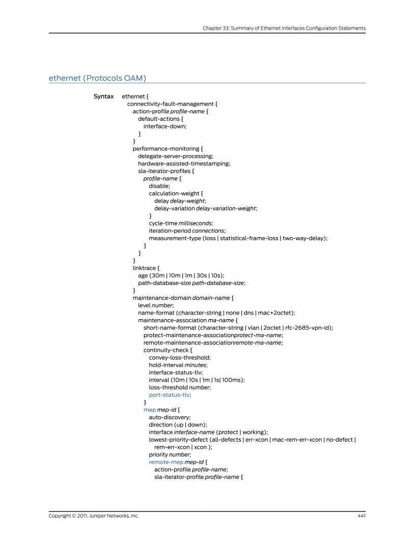
ethernet (Protocols OAM)
Syntax ethernet {connectivity-fault-management {action-profile profile-name {default-actions {interface-down;
}}performance-monitoring {delegate-server-processing;hardware-assisted-timestamping;sla-iterator-profiles {profile-name {disable;calculation-weight {delay delay-weight;delay-variation delay-variation-weight;
}cycle-timemilliseconds;iteration-period connections;measurement-type (loss | statistical-frame-loss | two-way-delay);
}}
}linktrace {age (30m | 10m | 1m | 30s | 10s);path-database-size path-database-size;
}maintenance-domain domain-name {level number;name-format (character-string | none | dns | mac+2octet);maintenance-associationma-name {short-name-format (character-string | vlan | 2octet | rfc-2685-vpn-id);protect-maintenance-associationprotect-ma-name;remote-maintenance-associationremote-ma-name;continuity-check {convey-loss-threshold;hold-intervalminutes;interface-status-tlv;interval (10m | 10s | 1m | 1s| 100ms);loss-threshold number;port-status-tlv;
}mepmep-id {auto-discovery;direction (up | down);interface interface-name (protect | working);lowest-priority-defect (all-defects | err-xcon | mac-rem-err-xcon | no-defect |rem-err-xcon | xcon );
priority number;remote-mepmep-id {action-profile profile-name;sla-iterator-profile profile-name {
441Copyright © 2011, Juniper Networks, Inc.
Chapter 33: Summary of Ethernet Interfaces Configuration Statements

data-tlv-size size;iteration-count count-value;priority priority-value;
}}
}}
}}evcs evc-id {evc-protocol cfmmanagement-domain domain-id (management-associationassociation-id | vpls (routing-instance instance-id);
remote-uni-count count;multipoint-to-multipoint;
}link-fault-management {action-profile profile-name {action {link-down;send-critical-event;syslog;
}event {link-adjacency-loss;link-event-rate {frame-error count;frame-period count;frame-period-summary count;symbol-period count;
}protocol-down;
}}interface interface-name {apply-action-profile;link-discovery (active | passive);pdu-interval interval;pdu-threshold threshold-value;remote-loopback;event-thresholds {frame-error count;frame-period count;frame-period-summary count;symbol-period count;
}negotiation-options {allow-remote-loopback;no-allow-link-events;
}}
}lmi {status-counter count;polling-verification-timer value;interface name {uni-id uni-name;
Copyright © 2011, Juniper Networks, Inc.442
Junos®
OS 11.4 Ethernet Interfaces Configuration Guide

status-counter number;polling-verification-timer value;evc-map-type (all-to-one-bundling | bundling | service-multiplexing);evc evc-name {default-evc;vlan-list vlan-id-list;
}}
}}
Hierarchy Level [edit protocols oam]
Release Information Statement introduced in Junos OS Release 8.2.
Description For Ethernet interfaces on M320, MX Series, and T Series routers, provide fault signaling
and detection for 802.3ah Operation, Administration, and Management (OAM) support.
The remaining statements are explained separately.
Required PrivilegeLevel
interface—To view this statement in the configuration.
interface-control—To add this statement to the configuration.
RelatedDocumentation
• Enabling IEEE 802.3ah OAM Support on page 290
• Example: Configuring Connectivity Fault Management for a PBB Network on MX Series
Routers
443Copyright © 2011, Juniper Networks, Inc.
Chapter 33: Summary of Ethernet Interfaces Configuration Statements
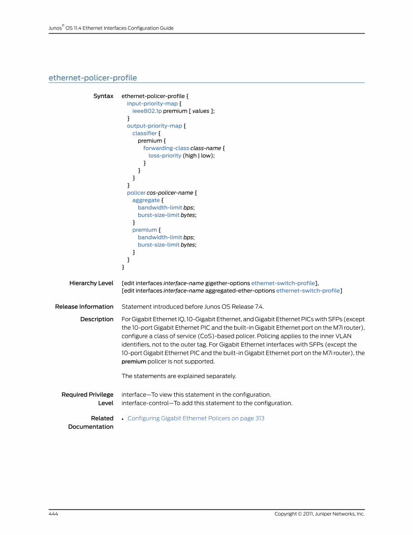
ethernet-policer-profile
Syntax ethernet-policer-profile {input-priority-map {ieee802.1p premium [ values ];
}output-priority-map {classifier {premium {forwarding-class class-name {loss-priority (high | low);
}}
}}policer cos-policer-name {aggregate {bandwidth-limit bps;burst-size-limit bytes;
}premium {bandwidth-limit bps;burst-size-limit bytes;
}}
}
Hierarchy Level [edit interfaces interface-name gigether-options ethernet-switch-profile],[edit interfaces interface-name aggregated-ether-options ethernet-switch-profile]
Release Information Statement introduced before Junos OS Release 7.4.
Description For Gigabit Ethernet IQ, 10-Gigabit Ethernet, and Gigabit Ethernet PICs with SFPs (except
the 10-port Gigabit Ethernet PIC and the built-in Gigabit Ethernet port on the M7i router),
configure a class of service (CoS)-based policer. Policing applies to the inner VLAN
identifiers, not to the outer tag. For Gigabit Ethernet interfaces with SFPs (except the
10-port Gigabit Ethernet PIC and the built-in Gigabit Ethernet port on the M7i router), the
premium policer is not supported.
The statements are explained separately.
Required PrivilegeLevel
interface—To view this statement in the configuration.
interface-control—To add this statement to the configuration.
RelatedDocumentation
• Configuring Gigabit Ethernet Policers on page 313
Copyright © 2011, Juniper Networks, Inc.444
Junos®
OS 11.4 Ethernet Interfaces Configuration Guide

ethernet-ring
Syntax ethernet-ring ring-name (east-interface {control-channel channel-name {vlan number;
}}guard-interval number;node-idmac-address;restore-interval number;ring-protection-link-owner;west-interface {control-channel channel-name {vlan number;
}}
}
Hierarchy Level [edit protocols protection-group]
Release Information Statement introduced in Junos OS Release 9.4.
Description For Ethernet PICs on MX Series routers, specify the Ethernet ring in an Ethernet ring
protection switching configuration.
Options The remaining statements are explained separately.
Required PrivilegeLevel
interface—To view this statement in the configuration.
interface-control—To add this statement to the configuration.
RelatedDocumentation
• Ethernet Ring Protection Switching Overview on page 413
445Copyright © 2011, Juniper Networks, Inc.
Chapter 33: Summary of Ethernet Interfaces Configuration Statements

ethernet-switch-profile
Syntax ethernet-switch-profile {ethernet-policer-profile {input-priority-map {ieee802.1p premium [ values ];
}output-priority-map {classifier {premium {forwarding-class class-name {loss-priority (high | low);
}}
}}policer cos-policer-name {aggregate {bandwidth-limit bps;burst-size-limit bytes;
}premium {bandwidth-limit bps;burst-size-limit bytes;
}}tag-protocol-id tpid;
}(mac-learn-enable | no-mac-learn-enable);
}
Hierarchy Level [edit interfaces interface-name gigether-options],[edit interfaces interface-name aggregated-ether-options]
Release Information Statement introduced before Junos OS Release 7.4.
Description For Gigabit Ethernet IQ, 10-Gigabit Ethernet IQ2 and IQ2-E, and Gigabit Ethernet PICs
with SFPs (except the 10-port Gigabit Ethernet PIC, aggregated Ethernet with Gigabit
Ethernet IQ interfaces, and the built-in Gigabit Ethernet port on the M7i router), configure
VLAN tag and MAC address accounting and filtering properties.
The statements are explained separately.
NOTE: When you gather interfaces into a bridge domain, theno-mac-learn-enable statement at the [edit interfaces interface-name
gigether-optionsethernet-switch-profile]hierarchy level is not supported. You
must use the no-mac-learning statement at the [edit bridge-domains
bridge-domain-name bridge-options interface interface-name] hierarchy level
to disable MAC learning on an interface in a bridge domain. For informationon disabling MAC learning for a bridge domain, see theMX Series Layer 2Configuration Guide.
Copyright © 2011, Juniper Networks, Inc.446
Junos®
OS 11.4 Ethernet Interfaces Configuration Guide

Default If theethernet-switch-profile statement is not configured, Gigabit Ethernet IQ and Gigabit
Ethernet PICs with SFPs (except the 10-port Gigabit Ethernet PIC and the built-in Gigabit
Ethernet port on the M7i router) behave like Gigabit Ethernet interfaces.
Required PrivilegeLevel
interface—To view this statement in the configuration.
interface-control—To add this statement to the configuration.
RelatedDocumentation
• Configuring Gigabit Ethernet Policers on page 313
• Configuring MAC Address Filtering on page 317
• Stacking and Rewriting Gigabit Ethernet VLAN Tags Overview on page 125
fastether-options
Syntax fastether-options {802.3ad {aex (primary | backup);lacp {port-priority;
}}(flow-control | no-flow-control);ignore-l3-incompletes;ingress-rate-limit rate;(loopback | no-loopback);mpls {pop-all-labels {required-depth number;
}}source-address-filter {mac-address;
}(source-filtering | no-source-filtering);
}
Hierarchy Level [edit interfaces interface-name]
Release Information Statement introduced before Junos OS Release 7.4.
Description Configure Fast Ethernet-specific interface properties.
The statements are explained separately.
Required PrivilegeLevel
interface—To view this statement in the configuration.
interface-control—To add this statement to the configuration.
RelatedDocumentation
• Ethernet Interfaces Overview on page 35
447Copyright © 2011, Juniper Networks, Inc.
Chapter 33: Summary of Ethernet Interfaces Configuration Statements
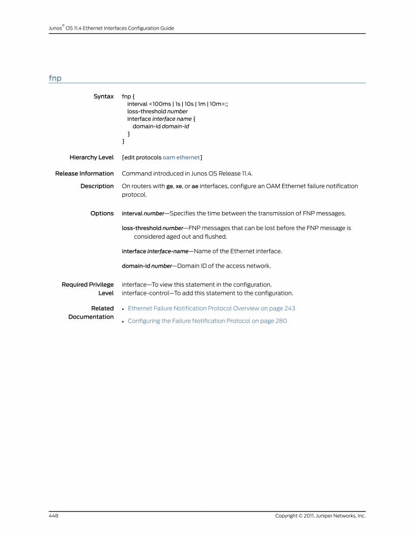
fnp
Syntax fnp {interval <100ms | 1s | 10s | 1m | 10m>;;loss-threshold numberinterface interface name {domain-id domain-id
}}
Hierarchy Level [edit protocols oam ethernet]
Release Information Command introduced in Junos OS Release 11.4.
Description On routers with ge, xe, or ae interfaces, configure an OAM Ethernet failure notification
protocol.
Options interval number—Specifies the time between the transmission of FNP messages.
loss-threshold number—FNP messages that can be lost before the FNP message is
considered aged out and flushed.
interface interface-name—Name of the Ethernet interface.
domain-id number—Domain ID of the access network.
Required PrivilegeLevel
interface—To view this statement in the configuration.
interface-control—To add this statement to the configuration.
RelatedDocumentation
• Ethernet Failure Notification Protocol Overview on page 243
• Configuring the Failure Notification Protocol on page 280
Copyright © 2011, Juniper Networks, Inc.448
Junos®
OS 11.4 Ethernet Interfaces Configuration Guide

flow-control
Syntax (flow-control | no-flow-control);
Hierarchy Level [edit interfaces interface-name aggregated-ether-options],[edit interfaces interface-name ether-options],[edit interfaces interface-name fastether-options],[edit interfaces interface-name gigether-options],[edit interfaces interface-namemultiservice-options],[edit interfaces interface-range name aggregated-ether-options],[edit interfaces interface-range name ether-options]
Release Information Statement introduced before Junos OS Release 7.4.
Statement introduced in Junos OS Release 9.0 in EX Series switches.
Description For aggregated Ethernet, Fast Ethernet, and Gigabit Ethernet interfaces only, explicitly
enable flow control, which regulates the flow of packets from the router or switch to the
remote side of the connection. Enabling flow control is useful when the remote device
is a Gigabit Ethernet switch. Flow control is not supported on the 4-port Fast Ethernet
PIC.
Default Flow control is enabled.
Required PrivilegeLevel
interface—To view this statement in the configuration.
interface-control—To add this statement to the configuration.
RelatedDocumentation
• Configuring Flow Control on page 45
• Configuring Gigabit Ethernet Interfaces (CLI Procedure)
449Copyright © 2011, Juniper Networks, Inc.
Chapter 33: Summary of Ethernet Interfaces Configuration Statements
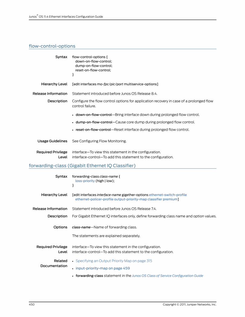
flow-control-options
Syntax flow-control-options {down-on-flow-control;dump-on-flow-control;reset-on-flow-control;
}
Hierarchy Level [edit interfacesmo-fpc/pic/portmultiservice-options]
Release Information Statement introduced before Junos OS Release 8.4.
Description Configure the flow control options for application recovery in case of a prolonged flow
control failure.
• down-on-flow-control—Bring interface down during prolonged flow control.
• dump-on-flow-control—Cause core dump during prolonged flow control.
• reset-on-flow-control—Reset interface during prolonged flow control.
Usage Guidelines See Configuring Flow Monitoring.
Required PrivilegeLevel
interface—To view this statement in the configuration.
interface-control—To add this statement to the configuration.
forwarding-class (Gigabit Ethernet IQ Classifier)
Syntax forwarding-class class-name {loss-priority (high | low);
}
Hierarchy Level [edit interfaces interface-name gigether-options ethernet-switch-profileethernet-policer-profile output-priority-map classifier premium]
Release Information Statement introduced before Junos OS Release 7.4.
Description For Gigabit Ethernet IQ interfaces only, define forwarding class name and option values.
Options class-name—Name of forwarding class.
The statements are explained separately.
Required PrivilegeLevel
interface—To view this statement in the configuration.
interface-control—To add this statement to the configuration.
RelatedDocumentation
• Specifying an Output Priority Map on page 315
• input-priority-map on page 459
• forwarding-class statement in the Junos OS Class of Service Configuration Guide
Copyright © 2011, Juniper Networks, Inc.450
Junos®
OS 11.4 Ethernet Interfaces Configuration Guide

forwarding-mode (100-Gigabit Ethernet)
Syntax forwarding-mode {(sa-multicast | ...the following vlan-steering statement...);vlan-steering {vlan-rule (high-low | odd-even);
}}
Hierarchy Level [edit chassis fpc slot pic slot]
Release Information Statement introduced in Junos OS Release 10.4.
Description Configure the interoperation mode for 100-Gigabit Ethernet PIC.
The remaining statements are explained separately.
Required PrivilegeLevel
interface—To view this statement in the configuration.
interface-control—To add this statement to the configuration.
RelatedDocumentation
• Configuring 100-Gigabit Ethernet PIC VLAN Steering Mode on page 361
• sa-multicast (100-Gigabit Ethernet) on page 506
• vlan-rule (100-Gigabit Ethernet) on page 535
• vlan-steering (100-Gigabit Ethernet) on page 536
451Copyright © 2011, Juniper Networks, Inc.
Chapter 33: Summary of Ethernet Interfaces Configuration Statements
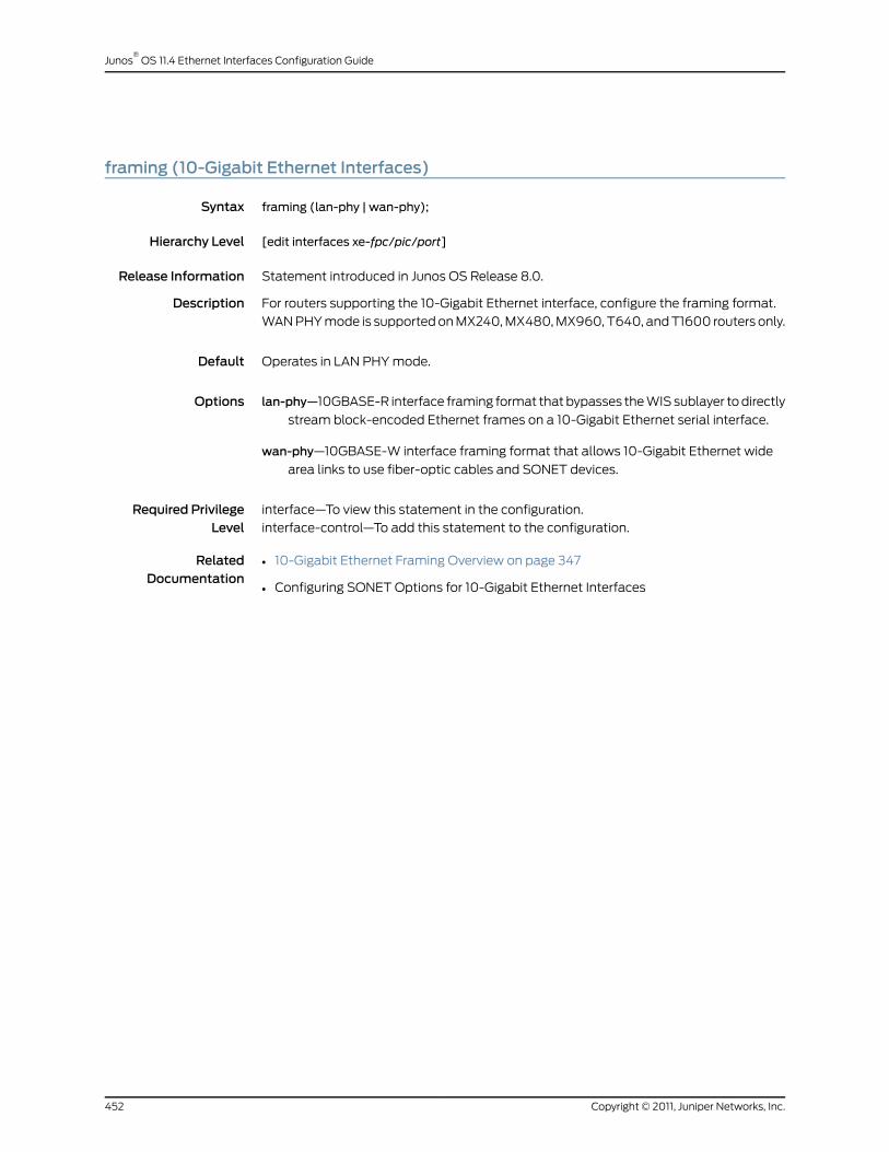
framing (10-Gigabit Ethernet Interfaces)
Syntax framing (lan-phy | wan-phy);
Hierarchy Level [edit interfaces xe-fpc/pic/port]
Release Information Statement introduced in Junos OS Release 8.0.
Description For routers supporting the 10-Gigabit Ethernet interface, configure the framing format.
WAN PHY mode is supported on MX240, MX480, MX960, T640, and T1600 routers only.
Default Operates in LAN PHY mode.
Options lan-phy—10GBASE-R interface framing format that bypasses the WIS sublayer to directly
stream block-encoded Ethernet frames on a 10-Gigabit Ethernet serial interface.
wan-phy—10GBASE-W interface framing format that allows 10-Gigabit Ethernet wide
area links to use fiber-optic cables and SONET devices.
Required PrivilegeLevel
interface—To view this statement in the configuration.
interface-control—To add this statement to the configuration.
RelatedDocumentation
• 10-Gigabit Ethernet Framing Overview on page 347
• Configuring SONET Options for 10-Gigabit Ethernet Interfaces
Copyright © 2011, Juniper Networks, Inc.452
Junos®
OS 11.4 Ethernet Interfaces Configuration Guide

gigether-options
Syntax gigether-options {802.3ad {aex (primary | backup);lacp {port-priority;
}}(asynchronous-notification | no-asynchronous-notification);(auto-negotiation | no-auto-negotiation) remote-fault <local-interface-online |local-interface-offline>;
(flow-control | no-flow-control);ignore-l3-incompletes;(loopback | no-loopback);mpls {pop-all-labels {required-depth number;
}}no-auto-mdixsource-address-filter {mac-address;
}(source-filtering | no-source-filtering);speedethernet-switch-profile {(mac-learn-enable | no-mac-learn-enable);tag-protocol-id [ tpids ];ethernet-policer-profile {input-priority-map {ieee802.1p premium [ values ];
}output-priority-map {classifier {premium {forwarding-class class-name {loss-priority (high | low);
}}
}}policer cos-policer-name {aggregate {bandwidth-limit bps;burst-size-limit bytes;
}premium {bandwidth-limit bps;burst-size-limit bytes;
}}
}}
453Copyright © 2011, Juniper Networks, Inc.
Chapter 33: Summary of Ethernet Interfaces Configuration Statements
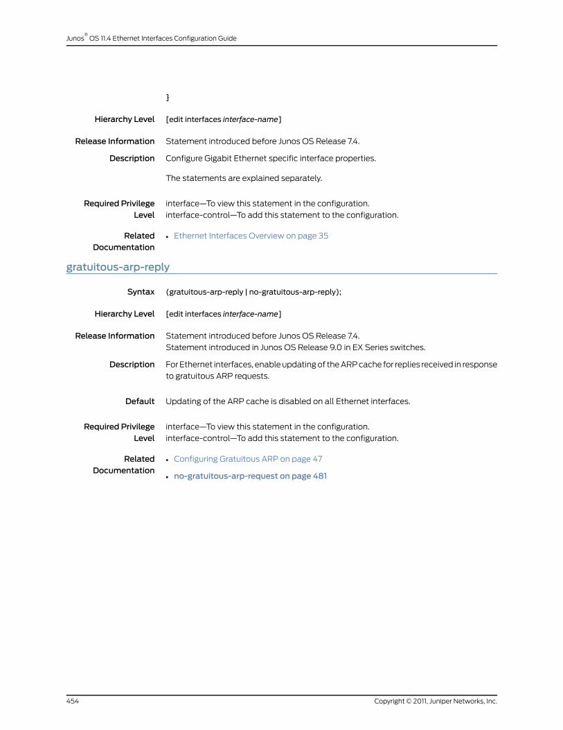
}
Hierarchy Level [edit interfaces interface-name]
Release Information Statement introduced before Junos OS Release 7.4.
Description Configure Gigabit Ethernet specific interface properties.
The statements are explained separately.
Required PrivilegeLevel
interface—To view this statement in the configuration.
interface-control—To add this statement to the configuration.
RelatedDocumentation
• Ethernet Interfaces Overview on page 35
gratuitous-arp-reply
Syntax (gratuitous-arp-reply | no-gratuitous-arp-reply);
Hierarchy Level [edit interfaces interface-name]
Release Information Statement introduced before Junos OS Release 7.4.
Statement introduced in Junos OS Release 9.0 in EX Series switches.
Description For Ethernet interfaces, enable updating of the ARP cache for replies received in response
to gratuitous ARP requests.
Default Updating of the ARP cache is disabled on all Ethernet interfaces.
Required PrivilegeLevel
interface—To view this statement in the configuration.
interface-control—To add this statement to the configuration.
RelatedDocumentation
• Configuring Gratuitous ARP on page 47
• no-gratuitous-arp-request on page 481
Copyright © 2011, Juniper Networks, Inc.454
Junos®
OS 11.4 Ethernet Interfaces Configuration Guide

hold-multiplier
Syntax hold-multiplier number;
Hierarchy Level [edit protocols lldp],[edit routing-instances routing-instance-name protocols lldp]
Release Information Statement introduced in Junos OS Release 9.6.
Description (MX Series and T Series routers only) Configure a value for the LLDP hold multiplier.
Hold timer interval in seconds to cache learned LLDP information before discarding.
Options number—Advertisement interval multiplier for LLDP cache discard.
Default: 4 (giving 120 second LLDP cache lifetime with other defaults)
Range: 2 through 10
Required PrivilegeLevel
routing—To view this statement in the configuration.
routing-control—To add this statement to the configuration.
RelatedDocumentation
• Configuring LLDP on page 154
ieee802.1p
Syntax ieee802.1p premium [ values ];
Hierarchy Level [edit interfaces interface-name gigether-options ethernet-switch-profileethernet-policer-profile input-priority-map]
Release Information Statement introduced before Junos Release 7.4.
Description For Gigabit Ethernet IQ and 10-Gigabit Ethernet interfaces only, configure premium priority
values for IEEE 802.1p input traffic.
Options values—Define IEEE 802.1p priority values to be treated as premium.
Range: 0 through 7
Required PrivilegeLevel
interface—To view this statement in the configuration.
interface-control—To add this statement to the configuration.
RelatedDocumentation
• Specifying an Input Priority Map on page 314
455Copyright © 2011, Juniper Networks, Inc.
Chapter 33: Summary of Ethernet Interfaces Configuration Statements

ignore-l3-incompletes
Syntax ignore-l3-incompletes;
Hierarchy Level [edit interfaces interface-name fastether-options],[edit interfaces interface-name gigether-options]
Release Information Statement introduced in Junos OS Release 9.0.
Description Ignore the counting of Layer 3 incomplete errors on Fast Ethernet, Gigabit Ethernet, and
10-Gigabit Ethernet interfaces.
Required PrivilegeLevel
interface—To view this statement in the configuration.
interface-control—To add this statement to the configuration.
RelatedDocumentation
• Ignoring Layer 3 Incomplete Errors on page 46
ingress-rate-limit
Syntax ingress-rate-limit rate;
Hierarchy Level [edit interfaces interface-name fastether-options]
Release Information Statement introduced before Junos OS Release 7.4.
Description Perform port-based rate limiting on ingress traffic arriving on Fast Ethernet 8-port, 12-port,
and 48-port PICs.
Options rate—Traffic rate, in megabits per second (Mbps).
Range: 1 through 100 Mbps
Required PrivilegeLevel
interface—To view this statement in the configuration.
interface-control—To add this statement to the configuration.
RelatedDocumentation
• Configuring the Ingress Rate Limit on page 50
Copyright © 2011, Juniper Networks, Inc.456
Junos®
OS 11.4 Ethernet Interfaces Configuration Guide

inner-tag-protocol-id
Syntax inner-tag-protocol-id tpid;
Hierarchy Level [edit interfaces interface-name unit logical-unit-number input-vlan-map],[edit interfaces interface-name unit logical-unit-number output-vlan-map],[edit logical-systems logical-system-name interfaces interface-nameunit logical-unit-numberinput-vlan-map],
[edit logical-systems logical-system-name interfaces interface-nameunit logical-unit-numberoutput-vlan-map]
Release Information Statement introduced in Junos OS Release 8.1.
Description For Gigabit Ethernet IQ, IQ2 and IQ2-E interfaces, and for aggregated Ethernet interfaces
using Gigabit Ethernet IQ2 and IQ2-E or 10-Gigabit Ethernet PICs on MX Series routers,
configure the IEEE 802.1Q TPID value to rewrite for the inner tag. All TPIDs you include
in input and output VLAN maps must be among those you specify at the [edit interfaces
interface-namegigether-optionsethernet-switch-profile tag-protocol-id [ tpids ]]hierarchy
level.
Default If the inner-tag-protocol-id statement is not configured, the TPID value is 0x8100.
Required PrivilegeLevel
interface—To view this statement in the configuration.
interface-control—To add this statement to the configuration.
RelatedDocumentation
• Configuring Inner and Outer TPIDs and VLAN IDs on page 131
457Copyright © 2011, Juniper Networks, Inc.
Chapter 33: Summary of Ethernet Interfaces Configuration Statements

inner-vlan-id
Syntax inner-vlan-id number;
Hierarchy Level [edit interfaces interface-name unit logical-unit-number input-vlan-map],[edit interfaces interface-name unit logical-unit-number output-vlan-map],[edit logical-systems logical-system-name interfaces interface-nameunit logical-unit-numberinput-vlan-map],
[edit logical-systems logical-system-name interfaces interface-nameunit logical-unit-numberoutput-vlan-map]
Release Information Statement introduced in Junos OS Release 8.1.
Description For Gigabit Ethernet IQ, IQ2 and IQ2-E interfaces, and for aggregated Ethernet interfaces
using Gigabit Ethernet IQ2 and IQ2-E or 10-Gigabit Ethernet PICs on MX Series routers,
specify the VLAN ID to rewrite for the inner tag of the final packet.
You cannot include the inner-vlan-id statement with the swap statement, swap-push
statement,push-pushstatement, orpush-swapstatement and the inner-vlan-idstatement
at the [edit interfaces interface-nameunit logical-unit-numberoutput-vlan-map] hierarchy
level. If you include any of those statements in the output VLAN map, the VLAN ID in the
outgoing frame is rewritten to the inner-vlan-id statement you include at the [edit
interfaces interface-name unit logical-unit-number] hierarchy level.
Options number—VLAN ID number.
Range: 0 through 4094
Required PrivilegeLevel
interface—To view this statement in the configuration.
interface-control—To add this statement to the configuration.
RelatedDocumentation
• Configuring Inner and Outer TPIDs and VLAN IDs on page 131
Copyright © 2011, Juniper Networks, Inc.458
Junos®
OS 11.4 Ethernet Interfaces Configuration Guide

inner-vlan-id-range
Syntax inner-vlan-id-range start start-id end end-id;
Hierarchy Level [edit interfaces interface-name unit logical-unit-number],[edit logical-systems logical-system-name interfaces interface-nameunit logical-unit-number],
Release Information Statement introduced in Junos OS Release 9.0.
Description The range of VLAN IDs to be used in the ATM-to-Ethernet interworking cross-connect.
Specify the starting VLAN ID and ending VLAN ID.
Options start-id—The lowest VLAN ID to be used.
end-id—The highest VLAN ID to be used.
Range: 32 through 4094
Required PrivilegeLevel
interface—To view this statement in the configuration.
interface-control—To add this statement to the configuration.
RelatedDocumentation
• Configuring ATM-to-Ethernet Interworking
input-priority-map
Syntax input-priority-map {ieee802.1p premium [ values ];
}
Hierarchy Level [edit interfaces interface-name gigether-options ethernet-switch-profileethernet-policer-profile]
Release Information Statement introduced before Junos OS Release 7.4.
Description For Gigabit Ethernet IQ and 10-Gigabit Ethernet interfaces only, define the input policer
priority map to be applied to incoming frames on this interface.
The statements are explained separately.
Required PrivilegeLevel
interface—To view this statement in the configuration.
interface-control—To add this statement to the configuration.
RelatedDocumentation
• Specifying an Input Priority Map on page 314
• output-priority-map on page 485
459Copyright © 2011, Juniper Networks, Inc.
Chapter 33: Summary of Ethernet Interfaces Configuration Statements
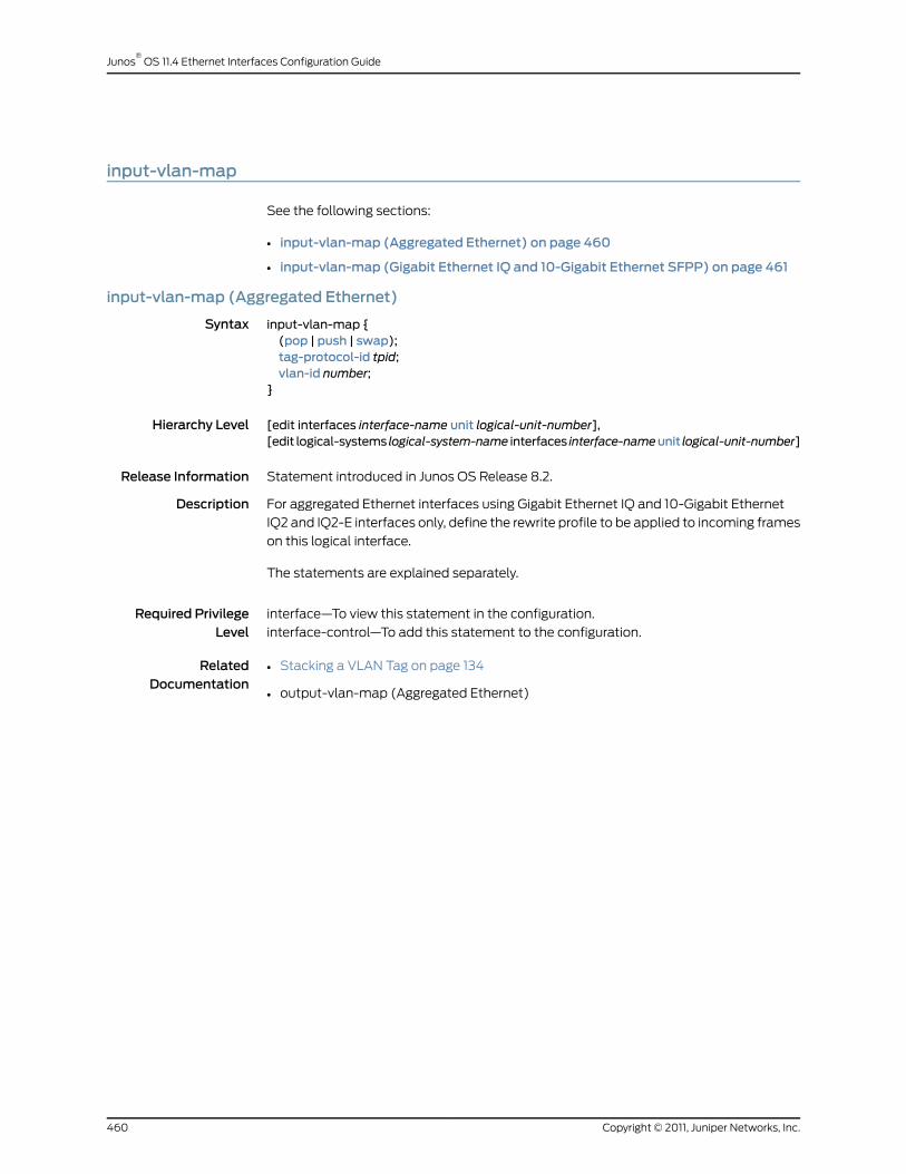
input-vlan-map
See the following sections:
• input-vlan-map (Aggregated Ethernet) on page 460
• input-vlan-map (Gigabit Ethernet IQ and 10-Gigabit Ethernet SFPP) on page 461
input-vlan-map (Aggregated Ethernet)
Syntax input-vlan-map {(pop | push | swap);tag-protocol-id tpid;vlan-id number;
}
Hierarchy Level [edit interfaces interface-name unit logical-unit-number],[edit logical-systems logical-system-name interfaces interface-nameunit logical-unit-number]
Release Information Statement introduced in Junos OS Release 8.2.
Description For aggregated Ethernet interfaces using Gigabit Ethernet IQ and 10-Gigabit Ethernet
IQ2 and IQ2-E interfaces only, define the rewrite profile to be applied to incoming frames
on this logical interface.
The statements are explained separately.
Required PrivilegeLevel
interface—To view this statement in the configuration.
interface-control—To add this statement to the configuration.
RelatedDocumentation
• Stacking a VLAN Tag on page 134
• output-vlan-map (Aggregated Ethernet)
Copyright © 2011, Juniper Networks, Inc.460
Junos®
OS 11.4 Ethernet Interfaces Configuration Guide

input-vlan-map (Gigabit Ethernet IQ and 10-Gigabit Ethernet SFPP)
Syntax input-vlan-map {(pop | pop-pop | pop-swap | push | push-push | swap | swap-push | swap-swap);inner-tag-protocol-id tpid;inner-vlan-id number;tag-protocol-id tpid;vlan-id number;
}
Hierarchy Level [edit interfaces interface-name unit logical-unit-number],[edit logical-systems logical-system-name interfaces interface-nameunit logical-unit-number]
Release Information Statement introduced before Junos OS Release 7.4.
pop-pop, pop-swap, push-push, swap-push, and swap-swap statements introduced in
Junos OS Release 8.1.
Description For Gigabit Ethernet IQ and 10-Gigabit Ethernet SFPP interfaces only, define the rewrite
profile to be applied to incoming frames on this logical interface.
The statements are explained separately.
Required PrivilegeLevel
interface—To view this statement in the configuration.
interface-control—To add this statement to the configuration.
RelatedDocumentation
• Stacking a VLAN Tag on page 134
• output-vlan-map (Gigabit Ethernet IQ and 10-Gigabit Ethernet with SFPP)
461Copyright © 2011, Juniper Networks, Inc.
Chapter 33: Summary of Ethernet Interfaces Configuration Statements

interface
Syntax interface (all | interface-name) {disable;
}
Hierarchy Level [edit protocols lldp],[edit routing-instances routing-instance-name protocols lldp]
Release Information Statement introduced in Junos OS Release 9.6.
Description (MX Series and T Series routers only) Specify an LLDP interface.
Options interface-name—A valid physical interface name.
NOTE: OnMX Series and T Series routers, you run LLDP on a physicalinterface, such as ge-1/0/0, and not at the logical interface (unit) level.
For information about interface names, see Interface Naming Overview. Forinformationabout interfacenames forTXMatrix routers, seeTXMatrixRouterChassis and Interface Names. For information about FPC numbering on TXMatrix routers, see Routing Matrix with a TXMatrix Router FPC Numbering.
all—Run LLDP on all interfaces.
disable—Disable LLDP on the specified interface
Required PrivilegeLevel
routing—To view this statement in the configuration.
routing-control—To add this statement to the configuration.
RelatedDocumentation
• Configuring LLDP on page 154
Copyright © 2011, Juniper Networks, Inc.462
Junos®
OS 11.4 Ethernet Interfaces Configuration Guide

interfaces
Syntax interfaces { ... }
Hierarchy Level [edit]
Release Information Statement introduced before Junos OS Release 7.4.
Description Configure interfaces on the router.
Default The management and internal Ethernet interfaces are automatically configured. You
must configure all other interfaces.
Required PrivilegeLevel
interface—To view this statement in the configuration.
interface-control—To add this statement to the configuration.
RelatedDocumentation
• Physical Interface Configuration Statements Overview
• Configuring Aggregated Ethernet Link Protection on page 107
463Copyright © 2011, Juniper Networks, Inc.
Chapter 33: Summary of Ethernet Interfaces Configuration Statements

lacp
See the following sections:
• lacp (802.3ad) on page 464
• lacp (Aggregated Ethernet) on page 465
lacp (802.3ad)
Syntax lacp {traceoptions {file lacpd;flag all;
}ppm (centralized | distributed);
}
Hierarchy Level [edit interfaces interface-name fastether-options 802.3ad],[edit interfaces interface-name gigether-options 802.3ad]
Release Information Statement introduced in Junos OS Release 9.3.
The ppm (centralized | distributed) option introduced in Junos OS Release 9.4.
Description For aggregated Ethernet interfaces only, configure the Link Aggregation Control Protocol
(LACP).
On MX Series routers you can specify distributed or centralized periodic packet
management (PPM).
Default If you do not specify lacp as either active or passive, LACP remains passive.
If you do not specify ppm as either centralized or distributed, PPM is distributed.
Options • active—Initiate transmission of LACP packets.
• passive—Respond to LACP packets.
• ppm—Set PPM to centralized or distributed.
The remaining statements are explained separately.
Required PrivilegeLevel
interface—To view this statement in the configuration.
interface-control—To add this statement to the configuration.
RelatedDocumentation
• Configuring Aggregated Ethernet LACP on page 109
Copyright © 2011, Juniper Networks, Inc.464
Junos®
OS 11.4 Ethernet Interfaces Configuration Guide
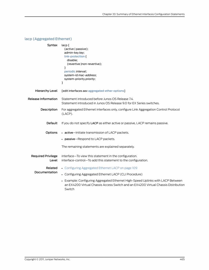
lacp (Aggregated Ethernet)
Syntax lacp {(active | passive);admin-key key;link-protection {disable;(revertive |non-revertive);
}periodic interval;system-idmac-address;system-priority priority;
}
Hierarchy Level [edit interfaces aex aggregated-ether-options]
Release Information Statement introduced before Junos OS Release 7.4.
Statement introduced in Junos OS Release 9.0 for EX Series switches.
Description For aggregated Ethernet interfaces only, configure Link Aggregation Control Protocol
(LACP).
Default If you do not specify LACP as either active or passive, LACP remains passive.
Options • active—Initiate transmission of LACP packets.
• passive—Respond to LACP packets.
The remaining statements are explained separately.
Required PrivilegeLevel
interface—To view this statement in the configuration.
interface-control—To add this statement to the configuration.
RelatedDocumentation
• Configuring Aggregated Ethernet LACP on page 109
• Configuring Aggregated Ethernet LACP (CLI Procedure)
• Example: Configuring Aggregated Ethernet High-Speed Uplinks with LACP Between
an EX4200 Virtual Chassis Access Switch and an EX4200 Virtual Chassis Distribution
Switch
465Copyright © 2011, Juniper Networks, Inc.
Chapter 33: Summary of Ethernet Interfaces Configuration Statements
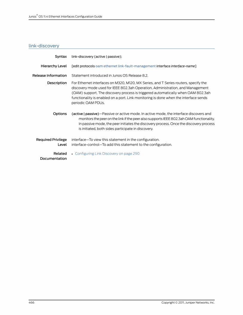
link-discovery
Syntax link-discovery (active | passive);
Hierarchy Level [edit protocols oam ethernet link-fault-management interface interface-name]
Release Information Statement introduced in Junos OS Release 8.2.
Description For Ethernet interfaces on M320, M120, MX Series, and T Series routers, specify the
discovery mode used for IEEE 802.3ah Operation, Administration, and Management
(OAM) support. The discovery process is triggered automatically when OAM 802.3ah
functionality is enabled on a port. Link monitoring is done when the interface sends
periodic OAM PDUs.
Options (active | passive)—Passive or active mode. In active mode, the interface discovers and
monitors the peer on the link if the peer also supports IEEE 802.3ah OAM functionality.
In passive mode, the peer initiates the discovery process. Once the discovery process
is initiated, both sides participate in discovery.
Required PrivilegeLevel
interface—To view this statement in the configuration.
interface-control—To add this statement to the configuration.
RelatedDocumentation
• Configuring Link Discovery on page 290
Copyright © 2011, Juniper Networks, Inc.466
Junos®
OS 11.4 Ethernet Interfaces Configuration Guide

link-fault-management
Syntax link-fault-management {action-profile profile-name {action {link-down;send-critical-event;syslog;
}event {link-adjacency-loss;link-event-rate {frame-error count;frame-period count;frame-period-summary count;symbol-period count;
}protocol-down;
}}interface interface-name {apply-action-profile profile-name;link-discovery (active | passive);pdu-interval interval;pdu-threshold threshold-value;remote-loopback;event-thresholds {frame-error count;frame-period count;frame-period-summary count;symbol-period count;
}negotiation-options {allow-remote-loopback;no-allow-link-events;
}}
}
Hierarchy Level [edit protocols oam ethernet]
Release Information Statement introduced in Junos OS Release 8.2.
Description For Ethernet interfaces on M320, M120, MX Series, and T Series routers, specify fault
signaling and detection for IEEE 802.3ah Operation, Administration, and Management
(OAM) support.
The remaining statements are explained separately.
Required PrivilegeLevel
interface—To view this statement in the configuration.
interface-control—To add this statement to the configuration.
467Copyright © 2011, Juniper Networks, Inc.
Chapter 33: Summary of Ethernet Interfaces Configuration Statements

RelatedDocumentation
• Enabling IEEE 802.3ah OAM Support on page 290
link-mode
Syntax link-modemode (automatic | full-duplex | half-duplex);
Hierarchy Level [edit interfaces interface-name],[edit interfaces interface-name ether-options],[edit interfaces ge-pim/0/0 switch-options switch-port port-number]
Release Information Statement introduced before Junos OS Release 7.4.
Statement introduced in Junos OS Release 9.0 for EX Series switches.
Description Set the device’s link connection characteristic.
Options mode—Link characteristics:
• automatic—Link mode is negotiated. This is the default for EX Series switches.
• full-duplex—Connection is full duplex.
• half-duplex—Connection is half duplex.
Default: Fast Ethernet interfaces, except the J Series ePIM Fast Ethernet interfaces, can
operate in either full-duplex or half-duplex mode. The router’s management Ethernet
interface, fxp0 or em0, the built-in Fast Ethernet interfaces on the FIC (M7i router),
and the Gigabit Ethernet ports on J Series Services Routers with uPIMs installed and
configured for access switching mode autonegotiate whether to operate in full-duplex
or half-duplex mode. Unless otherwise noted here, all other interfaces operate only
in full-duplex mode.
NOTE: On J Series ePIM Fast Ethernet interfaces, if you specify half-duplex(or if full-duplexmode is not autonegotiated), the followingmessage iswritten to the system log: "Half-duplexmode not supported on this PIC,forcing full-duplexmode."
NOTE: On EX Series switches, if no-auto-negotiation is specified in [edit
interfaces interface-name ether-options], you can select only full-duplex
or half-duplex. If auto-negotiation is specified, you can select anymode.
Required PrivilegeLevel
interface—To view this statement in the configuration.
interface-control—To add this statement to the configuration.
RelatedDocumentation
• Configuring the Link Characteristics on Ethernet Interfaces on page 46
• Understanding Management Ethernet Interfaces
Copyright © 2011, Juniper Networks, Inc.468
Junos®
OS 11.4 Ethernet Interfaces Configuration Guide

link-protection
Syntax link–protection {disable;(revertive |non-revertive);
}
Hierarchy Level [edit interfaces aex aggregated-ether-options][edit interfaces aex aggregated-ether-options lacp]
Release Information Statement introduced in Junos OS Release 8.3.
Statement introduced in Junos OS Release 9.0 for EX Series switches.
Support for disable, revertive, and non-revertive statements added in Junos OS Release
9.3.
Description On the router, for aggregated Ethernet interfaces only, configure link protection. In addition
to enabling link protection, a primary and a secondary (backup) link must be configured
to specify what links egress traffic should traverse. To configure primary and secondary
links on the router, include the primary and backup statements at the [edit interfaces
ge-fpc/pic/port gigether-options 802.3ad aex] hierarchy level or the [edit interfaces
fe-fpc/pic/port fastether-options 802.3ad aex] hierarchy level.
To configure those links on the switch, configure those statements at the [edit interfaces
ge-fpc/pic/port ether-options 802.3ad aex] hierarchy level or at the [edit interfaces
xe-fpc/pic/port ether-options 802.3ad aex] hierarchy level.
Options The statements are explained separately.
Required PrivilegeLevel
interface—To view this statement in the configuration.
interface-control—To add this statement to the configuration.
RelatedDocumentation
• Configuring Aggregated Ethernet Link Protection on page 107
469Copyright © 2011, Juniper Networks, Inc.
Chapter 33: Summary of Ethernet Interfaces Configuration Statements

link-speed (Aggregated Ethernet)
Syntax link-speed speed;
Hierarchy Level [edit interfaces aex aggregated-ether-options],[edit interfaces interface-range name aggregated-ether-options],[edit interfaces interface-range name aggregated-sonet-options]
Release Information Statement introduced before Junos OS Release 7.4.
Statement introduced in Junos OS Release 9.0 for EX Series switches.
Description For aggregated Ethernet interfaces only, set the required link speed.
Options speed—For aggregated Ethernet links, you can specify speed in bits per second either as
a complete decimal number or as a decimal number followed by the abbreviation
k (1000), m (1,000,000), or g (1,000,000,000).
Aggregated Ethernet links on the M120 router can have one of the following speed values:
• 100m—Links are 100 Mbps.
• 10g—Links are 10 Gbps.
• 1g—Links are 1 Gbps.
• oc192—Links are OC192 or STM64c.
Aggregated Ethernet links on EX Series switches can be configured to operate at one of
the following speed values:
• 10m
• 100m
• 1g
• 10g
Required PrivilegeLevel
interface—To view this statement in the configuration.
interface-control—To add this statement to the configuration.
RelatedDocumentation
• Configuring Aggregated Ethernet Link Speed on page 117
• Configuring Aggregated Ethernet Interfaces (CLI Procedure)
• Example: Configuring Aggregated Ethernet High-Speed Uplinks Between an EX4200
Virtual Chassis Access Switch and an EX4200 Virtual Chassis Distribution Switch
Copyright © 2011, Juniper Networks, Inc.470
Junos®
OS 11.4 Ethernet Interfaces Configuration Guide

lldp
Syntax lldp {advertisement-interval seconds;disable;hold-multiplier number;interface (all | interface-name) {disable;
}lldp-configuration-notification-interval seconds;ptopo-configuration-maximum-hold-time seconds;ptopo-configuration-trap-interval seconds;traceoptions {file filename <files number> <sizemaximum-file-size> <world-readable |no-world-readable>;
flag flag <disable>;}
}
Hierarchy Level [edit protocols],[edit routing-instances routing-instance-name protocols]
Release Information Statement introduced in Junos OS Release 9.6.
Description (MX Series and T Series routers only) Specify LLDP configuration parameters.
Options The statements are explained separately.
Required PrivilegeLevel
routing—To view this statement in the configuration.
routing-control—To add this statement to the configuration.
RelatedDocumentation
• Configuring LLDP on page 154
471Copyright © 2011, Juniper Networks, Inc.
Chapter 33: Summary of Ethernet Interfaces Configuration Statements
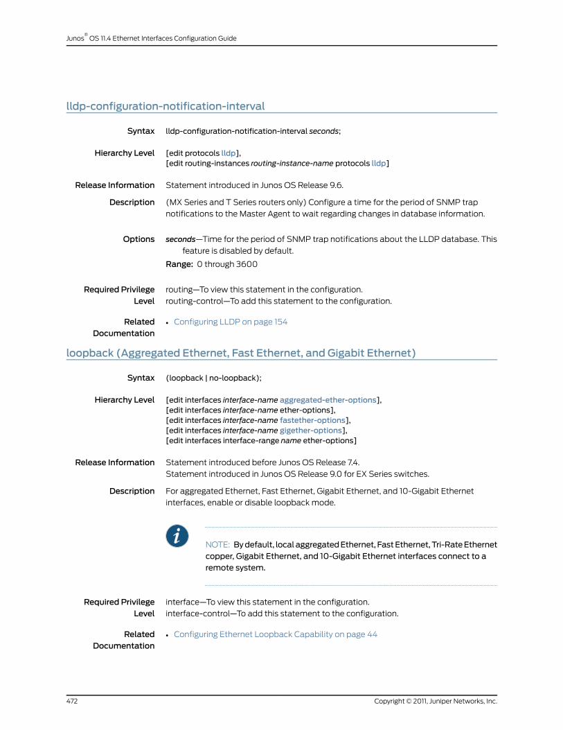
lldp-configuration-notification-interval
Syntax lldp-configuration-notification-interval seconds;
Hierarchy Level [edit protocols lldp],[edit routing-instances routing-instance-name protocols lldp]
Release Information Statement introduced in Junos OS Release 9.6.
Description (MX Series and T Series routers only) Configure a time for the period of SNMP trap
notifications to the Master Agent to wait regarding changes in database information.
Options seconds—Time for the period of SNMP trap notifications about the LLDP database. This
feature is disabled by default.
Range: 0 through 3600
Required PrivilegeLevel
routing—To view this statement in the configuration.
routing-control—To add this statement to the configuration.
RelatedDocumentation
• Configuring LLDP on page 154
loopback (Aggregated Ethernet, Fast Ethernet, and Gigabit Ethernet)
Syntax (loopback | no-loopback);
Hierarchy Level [edit interfaces interface-name aggregated-ether-options],[edit interfaces interface-name ether-options],[edit interfaces interface-name fastether-options],[edit interfaces interface-name gigether-options],[edit interfaces interface-range name ether-options]
Release Information Statement introduced before Junos OS Release 7.4.
Statement introduced in Junos OS Release 9.0 for EX Series switches.
Description For aggregated Ethernet, Fast Ethernet, Gigabit Ethernet, and 10-Gigabit Ethernet
interfaces, enable or disable loopback mode.
NOTE: Bydefault, localaggregatedEthernet, FastEthernet,Tri-RateEthernetcopper, Gigabit Ethernet, and 10-Gigabit Ethernet interfaces connect to aremote system.
Required PrivilegeLevel
interface—To view this statement in the configuration.
interface-control—To add this statement to the configuration.
RelatedDocumentation
• Configuring Ethernet Loopback Capability on page 44
Copyright © 2011, Juniper Networks, Inc.472
Junos®
OS 11.4 Ethernet Interfaces Configuration Guide
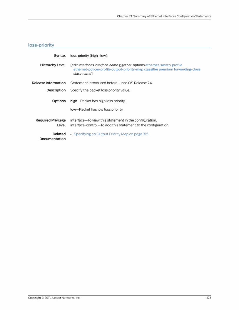
loss-priority
Syntax loss-priority (high | low);
Hierarchy Level [edit interfaces interface-name gigether-options ethernet-switch-profileethernet-policer-profile output-priority-map classifier premium forwarding-classclass-name]
Release Information Statement introduced before Junos OS Release 7.4.
Description Specify the packet loss priority value.
Options high—Packet has high loss priority.
low—Packet has low loss priority.
Required PrivilegeLevel
interface—To view this statement in the configuration.
interface-control—To add this statement to the configuration.
RelatedDocumentation
• Specifying an Output Priority Map on page 315
473Copyright © 2011, Juniper Networks, Inc.
Chapter 33: Summary of Ethernet Interfaces Configuration Statements
mac-learn-enable
Syntax (mac-learn-enable | no-mac-learn-enable);
Hierarchy Level [edit interfaces interface-name gigether-options ethernet-switch-profile]
Release Information Statement introduced before Junos OS Release 7.4.
Description For Gigabit Ethernet IQ and Gigabit Ethernet PICs with SFPs (except the 10-port Gigabit
Ethernet PIC and the built-in Gigabit Ethernet port on the M7i router), and for Gigabit
Ethernet DPCs on MX Series routers, configure whether source and destination MAC
addresses are dynamically learned:
• mac-learn-enable—Allow the interface to dynamically learn source and destination
MAC addresses.
• no-mac-learn-enable—Prohibit the interface from dynamically learning source and
destination MAC addresses.
MAC address learning is based on source addresses. You can start accounting for traffic
after there has been traffic sent from the MAC address. Once the MAC address is learned,
the frames and bytes transmitted to or received from the MAC address can be tracked.
NOTE: When you gather interfaces into a bridge domain, theno-mac-learn-enable statement at the [edit interfaces interface-name
gigether-optionsethernet-switch-profile]hierarchy level is not supported. You
must use the no-mac-learning statement at the [edit bridge-domains
bridge-domain-name bridge-options interface interface-name] hierarchy level
to disable MAC learning on an interface in a bridge domain. For informationon disabling MAC learning for a bridge domain, seeMX Series Layer 2Configuration Guide.
Required PrivilegeLevel
interface—To view this statement in the configuration.
interface-control—To add this statement to the configuration.
RelatedDocumentation
• Configuring MAC Address Filtering on page 317
Copyright © 2011, Juniper Networks, Inc.474
Junos®
OS 11.4 Ethernet Interfaces Configuration Guide

max-sessions (PPPoE Service Name Tables)
Syntax max-sessions number;
Hierarchy Level [edit protocols pppoe service-name-tables table-name service service-name],
Release Information Statement introduced in Junos OS Release 10.2.
Description Configure the maximum number of active PPPoE sessions using either static or dynamic
PPPoE interfaces that the router can establish with the specified named service, empty
service, or any service entry in a PPPoE service name table. The router maintains a count
of active PPPoE sessions for each service entry to determine when the maximum sessions
limit has been reached.
The router uses the max-sessions value for a PPPoE service name table entry in
conjunction with the max-sessions value configured for the PPPoE underlying interface,
and with the maximum number of PPPoE sessions supported on your router. If your
configuration exceeds any of these maximum session limits, the router is unable to
establish the PPPoE session.
Options number—Maximum number of active PPPoE sessions that the router can establish with
the specified PPPoE service name table entry, in the range 1 to the platform-specific
maximum PPPoE sessions supported for your router. The default value is equal to
the maximum number of PPPoE sessions supported on your routing platform.
For information about scaling values for PPPoE interfaces, access the Subscriber
Management Scaling Values (XLS) spreadsheet from the Downloads box on the
Junos OS Subscriber Management pathway page for the current release.
Required PrivilegeLevel
interface—To view this statement in the configuration.
interface-control—To add this statement to the configuration.
RelatedDocumentation
• Limiting the Number of Active PPPoE Sessions Established with a Specified Service
Name on page 394
• Configuring PPPoE Service Name Tables on page 388
• PPPoE Maximum Session Limit Overview
• For information about configuring dynamic PPPoE subscriber interfaces, see the Junos
OS Subscriber Access Configuration Guide
• For information about configuring static PPPoE interfaces, see the Junos OS Ethernet
Interfaces Configuration Guide
475Copyright © 2011, Juniper Networks, Inc.
Chapter 33: Summary of Ethernet Interfaces Configuration Statements

max-sessions-vsa-ignore (Static and Dynamic Subscribers)
Syntax max-sessions-vsa-ignore;
Hierarchy Level [edit dynamic-profiles profile-name interfaces demux0 unit logical-unit-number familypppoe],
[editdynamic-profilesprofile-name interfaces interface-nameunit logical-unit-number familypppoe],
[edit dynamic-profiles profile-name interfaces interface-name unit logical-unit-numberpppoe-underlying-options],
[edit interfaces interface-name unit logical-unit-number family pppoe],[edit interfaces interface-name unit logical-unit-number pppoe-underlying-options],[edit logical-systems logical-system-name interfaces interface-nameunit logical-unit-numberfamily pppoe],
[edit logical-systems logical-system-name interfaces interface-nameunit logical-unit-numberpppoe-underlying-options]
Release Information Statement introduced in Junos OS Release 11.4.
Description Configure the router to ignore (clear) the value returned by RADIUS in the
Max-Clients-Per-Interface Juniper Networks vendor-specific attribute (VSA) [26-143],
and restore the PPPoE maximum session value on the underlying interface to the value
configured in the CLI with the max-sessions statement. The PPPoE maximum session
value specifies the maximum number of concurrent static or dynamic PPPoE logical
interfaces (sessions) that the router can activate on the PPPoE underlying interface, or
the maximum number of active static or dynamic PPPoE sessions that the router can
establish with a particular service entry in a PPPoE service name table.
Default If you do not include themax-sessions-vsa-ignore statement, the maximum session value
returned by RADIUS in the Max-Clients-Per-Interface VSA takes precedence over the
PPPoE maximum session value configured with the max-sessions statement.
Required PrivilegeLevel
interface—To view this statement in the configuration.
interface-control—To add this statement to the configuration.
RelatedDocumentation
• Limiting the Maximum Number of PPPoE Sessions on the Underlying Interface
• PPPoE Maximum Session Limit Overview
• Guidelines for Using PPPoE Maximum Session Limit from RADIUS
• Juniper Networks VSAs Supported by the AAA Service Framework
• For information about configuring dynamic PPPoE subscriber interfaces, see the Junos
OS Subscriber Access Configuration Guide
• For information about configuring static PPPoE interfaces, see the Junos OS Ethernet
Interfaces Configuration Guide
Copyright © 2011, Juniper Networks, Inc.476
Junos®
OS 11.4 Ethernet Interfaces Configuration Guide

mep
Syntax mepmep-id {auto-discovery;direction (up | down);interface interface-name (protect | working);priority number;remote-mepmep-id {action-profile profile-name;sla-iterator-profile profile-name {data-tlv-size size;iteration-count count-value;priority priority-value;
}}
}
Hierarchy Level [editprotocolsoamethernetconnectivity-fault-managementmaintenance-domainmd-namemaintenance-associationma-name]
Release Information Statement introduced in Junos OS Release 8.4.
Description The numeric identifier of the maintenance association end point (MEP) within the
maintenance association.
Options mep-id—Specify the numeric identifier of the MEP.
Range: 1 through 8191
The remaining statements are explained separately.
Required PrivilegeLevel
interface—To view this statement in the configuration.
interface-control—To add this statement to the configuration.
RelatedDocumentation
• Configuring a Maintenance Endpoint on page 186
• Example: Configuring Connectivity Fault Management for a PBB Network on MX Series
Routers
477Copyright © 2011, Juniper Networks, Inc.
Chapter 33: Summary of Ethernet Interfaces Configuration Statements

minimum-links
Syntax minimum-links number;
Hierarchy Level [edit interfaces aex aggregated-ether-options],[edit interfaces aex aggregated-sonet-options],[edit interfaces interface-namemlfr-uni-nni-bundle-options],[edit interfaces interface-name unit logical-unit-number],[edit interfaces interface-range range aggregated-ether-options],[edit interfaces interface-range range aggregated-sonet-options],[edit logical-systems logical-system-name interfaces interface-nameunit logical-unit-number]
Release Information Statement introduced before Junos OS Release 7.4.
Statement introduced in Junos OS Release 9.0 for EX Series switches.
Description For aggregated Ethernet, SONET/SDH, multilink, link services, and voice services interfaces
only, set the minimum number of links that must be up for the bundle to be labeled up.
Options number—Number of links.
Range: 1 through 8 (1 through 16 for Ethernet and SONET interfaces on the MX Series,
M320, M120, T Series, or TX Matrix routers, and 1 through 12 for EX8200 switches)
Default: 1
Required PrivilegeLevel
interface—To view this statement in the configuration.
interface-control—To add this statement to the configuration.
RelatedDocumentation
• Configuring Aggregated Ethernet Minimum Links on page 117
• Configuring Aggregated SONET/SDH Minimum Links
• Configuring Aggregated Ethernet Interfaces (CLI Procedure)
• Example: Configuring Aggregated Ethernet High-Speed Uplinks Between an EX4200
Virtual Chassis Access Switch and an EX4200 Virtual Chassis Distribution Switch
• Junos OS Services Interfaces Configuration Guide
Copyright © 2011, Juniper Networks, Inc.478
Junos®
OS 11.4 Ethernet Interfaces Configuration Guide

mip-half-function
Syntax mip-half-function (none | default | explicit);
Hierarchy Level [edit protocols oam ethernet connectivity-fault-managementmaintenance-domainmd-name],
[edit protocols oam ethernet connectivity-fault-managementmaintenance-associationma-name]
Release Information Statement introduced in Junos OS Release 9.6.
Description Specify the OAM Ethernet CFM maintenance domain MIP half functions.
NOTE: Whenever a MIP is configured and a bridge domain is mapped tomultiple maintenance domains or maintenance associations, it is essentialthat themip-half-function value for all maintenance domains and
maintenance associations are the same.
Options none—Specify to not use the mip-half-function.
default—Specify to use the default mip-half-function.
explicit—Specify an explicit mip-half-function.
Required PrivilegeLevel
interface—To view this statement in the configuration.
interface-control—To add this statement to the configuration.
RelatedDocumentation
• Creating the Maintenance Domain on page 179
• Example: Configuring Connectivity Fault Management for a PBB Network on MX Series
Routers
• maintenance-domain
479Copyright © 2011, Juniper Networks, Inc.
Chapter 33: Summary of Ethernet Interfaces Configuration Statements

mpls
Syntax mpls {pop-all-labels {required-depth number;
}}
Hierarchy Level [edit interfaces interface-name atm-options],[edit interfaces interface-name sonet-options],[edit interfaces interface-name fastether-options],[edit interfaces interface-name gigether-options]
Release Information Statement introduced before Junos OS Release 7.4.
Description For passive monitoring on ATM and SONET/SDH interfaces and 10-Gigabit Ethernet
interfaces in WAN PHY mode, process incoming IP packets that have MPLS labels.
The remaining statements are explained separately.
Required PrivilegeLevel
interface—To view this statement in the configuration.
interface-control—To add this statement to the configuration.
RelatedDocumentation
• Removing MPLS Labels from Incoming Packets
• Removing MPLS Labels from Incoming Packet
• Junos OS Services Interfaces Configuration Guide
no-auto-mdix
Syntax no-auto-mdix;
Hierarchy Level [edit interface ge-fpc/port/pic gigether-options]
Description On MX Series routers, disable the Auto MDI/MDIX feature.
MX Series routers with Gigabit Ethernet interfaces automatically detect MDI and MDIX
port connections. Use this statement to override the default setting. Remove this
statement to return to the default setting.
Default Auto MDI/MDIX is enabled by default.
Options There are no options for this statement.
Required PrivilegeLevel
interface—To view this statement in the configuration.
interface-control—To add this statement to the configuration.
RelatedDocumentation
• Ethernet Interfaces Overview on page 35
• gigether-options on page 453.
Copyright © 2011, Juniper Networks, Inc.480
Junos®
OS 11.4 Ethernet Interfaces Configuration Guide

no-gratuitous-arp-request
Syntax no-gratuitous-arp-request;
Hierarchy Level [edit interfaces interface-name]
Release Information Statement introduced in Junos OS Release 9.6 for EX Series switches.
Description For Ethernet interfaces, do not respond to gratuitous ARP requests.
Default Gratuitous ARP responses are enabled on all Ethernet interfaces.
Required PrivilegeLevel
interface—To view this statement in the configuration.
interface-control—To add this statement to the configuration.
RelatedDocumentation
• Configuring Gratuitous ARP on page 47
• gratuitous-arp-reply on page 454
481Copyright © 2011, Juniper Networks, Inc.
Chapter 33: Summary of Ethernet Interfaces Configuration Statements

oam
Syntax oam {ethernet {connectivity-fault-management {action-profile profile-name {default-actions {interface-down;
}}performance-monitoring {delegate-server-processing;hardware-assisted-timestamping;sla-iterator-profiles {profile-name {disable;calculation-weight {delay delay-weight;delay-variation delay-variation-weight;
}cycle-timemilliseconds;iteration-period connections;measurement-type (loss | statistical-frame-loss | two-way-delay);
}}
}linktrace {age (30m | 10m | 1m | 30s | 10s);path-database-size path-database-size;
}maintenance-domain domain-name {level number;name-format (character-string | none | dns | mac+2octet);maintenance-associationma-name {short-name-format (character-string | vlan | 2octet | rfc-2685-vpn-id);protect-maintenance-associationprotect-ma-name;remote-maintenance-associationremote-ma-name;continuity-check {convey-loss-threshold;hold-intervalminutes;interface-status-tlv;interval (10m | 10s | 1m | 1s| 100ms);loss-threshold number;port-status-tlv;
}mepmep-id {auto-discovery;direction (up | down);interface interface-name (protect | working);lowest-priority-defect (all-defects | err-xcon | mac-rem-err-xcon | no-defect |rem-err-xcon | xcon );
priority number;remote-mepmep-id {action-profile profile-name;
Copyright © 2011, Juniper Networks, Inc.482
Junos®
OS 11.4 Ethernet Interfaces Configuration Guide
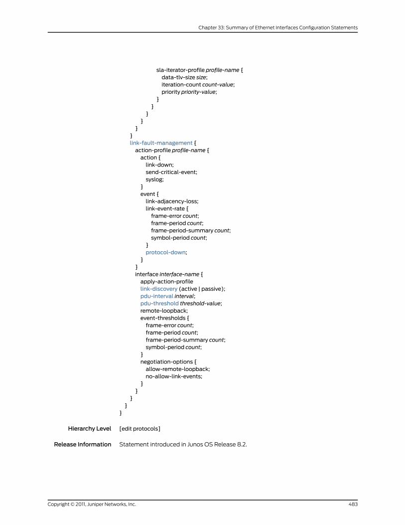
sla-iterator-profile profile-name {data-tlv-size size;iteration-count count-value;priority priority-value;
}}
}}
}}link-fault-management {action-profile profile-name {action {link-down;send-critical-event;syslog;
}event {link-adjacency-loss;link-event-rate {frame-error count;frame-period count;frame-period-summary count;symbol-period count;
}protocol-down;
}}interface interface-name {apply-action-profilelink-discovery (active | passive);pdu-interval interval;pdu-threshold threshold-value;remote-loopback;event-thresholds {frame-error count;frame-period count;frame-period-summary count;symbol-period count;
}negotiation-options {allow-remote-loopback;no-allow-link-events;
}}
}}
}
Hierarchy Level [edit protocols]
Release Information Statement introduced in Junos OS Release 8.2.
483Copyright © 2011, Juniper Networks, Inc.
Chapter 33: Summary of Ethernet Interfaces Configuration Statements

Description For Ethernet interfaces on M320, M120, MX Series, and T Series routers, provide IEEE
802.3ah Operation, Administration, and Management (OAM) support.
The remaining statements are explained separately.
Required PrivilegeLevel
interface—To view this statement in the configuration.
interface-control—To add this statement to the configuration.
RelatedDocumentation
• IEEE 802.3ah OAM Link-Fault Management Overview on page 287
optics-options
Syntax optics-options {alarm low–light–alarm {(link-down | syslog);
}warning low–light–warning {(link-down | syslog);
}wavelength nm;
}
Hierarchy Level [edit interfaces interface-name]
Release Information Statement introduced before Junos OS Release 7.4.
alarm option and warning options introduced in Junos OS Release 10.0.
Description For 10-Gigabit Ethernet dense wavelength-division multiplexing (DWDM) interfaces only,
configure full C-band International Telecommunication Union (ITU)-Grid tunable optics.
Options The alarm and warning and wavelength statements are explained separately.
Required PrivilegeLevel
interface—To view this statement in the configuration.
interface-control—To add this statement to the configuration.
RelatedDocumentation
• 10-Gigabit Ethernet DWDM Interface Wavelength Overview on page 345
Copyright © 2011, Juniper Networks, Inc.484
Junos®
OS 11.4 Ethernet Interfaces Configuration Guide
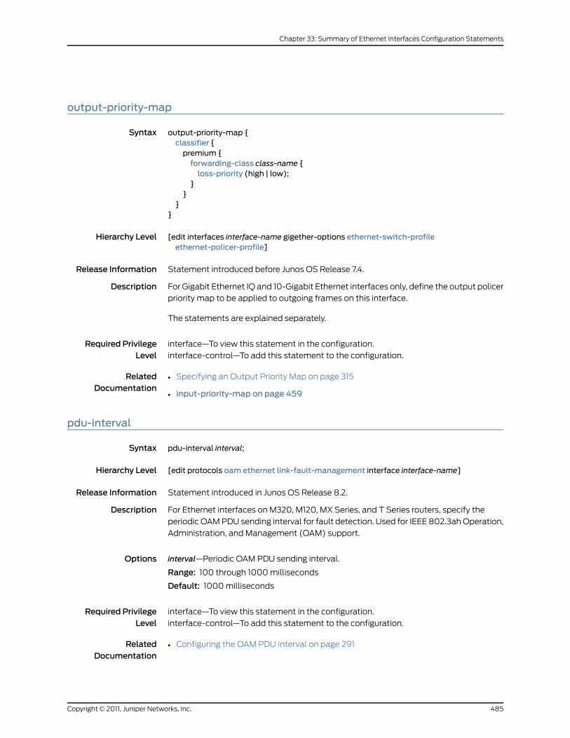
output-priority-map
Syntax output-priority-map {classifier {premium {forwarding-class class-name {loss-priority (high | low);
}}
}}
Hierarchy Level [edit interfaces interface-name gigether-options ethernet-switch-profileethernet-policer-profile]
Release Information Statement introduced before Junos OS Release 7.4.
Description For Gigabit Ethernet IQ and 10-Gigabit Ethernet interfaces only, define the output policer
priority map to be applied to outgoing frames on this interface.
The statements are explained separately.
Required PrivilegeLevel
interface—To view this statement in the configuration.
interface-control—To add this statement to the configuration.
RelatedDocumentation
• Specifying an Output Priority Map on page 315
• input-priority-map on page 459
pdu-interval
Syntax pdu-interval interval;
Hierarchy Level [edit protocols oam ethernet link-fault-management interface interface-name]
Release Information Statement introduced in Junos OS Release 8.2.
Description For Ethernet interfaces on M320, M120, MX Series, and T Series routers, specify the
periodic OAM PDU sending interval for fault detection. Used for IEEE 802.3ah Operation,
Administration, and Management (OAM) support.
Options interval—Periodic OAM PDU sending interval.
Range: 100 through 1000 milliseconds
Default: 1000 milliseconds
Required PrivilegeLevel
interface—To view this statement in the configuration.
interface-control—To add this statement to the configuration.
RelatedDocumentation
• Configuring the OAM PDU Interval on page 291
485Copyright © 2011, Juniper Networks, Inc.
Chapter 33: Summary of Ethernet Interfaces Configuration Statements

pdu-threshold
Syntax pdu-threshold threshold-value;
Hierarchy Level [edit protocols oam ethernet link-fault-management interface interface-name]
Release Information Statement introduced in Junos OS Release 8.2.
Description For Ethernet interfaces on M320, M120, MX Series, and T Series routers, specify the
number of OAM PDUs to miss before an error is logged. Used for IEEE 802.3ah Operation,
Administration, and Management (OAM) support.
Options threshold-value—The number of PDUs missed before declaring the peer lost.
Range: 3 through 10 PDUs
Default: 3 PDUs
Required PrivilegeLevel
interface—To view this statement in the configuration.
interface-control—To add this statement to the configuration.
RelatedDocumentation
• Configuring the OAM PDU Threshold on page 292
Copyright © 2011, Juniper Networks, Inc.486
Junos®
OS 11.4 Ethernet Interfaces Configuration Guide

periodic
Syntax periodic interval;
Hierarchy Level [edit interfaces aex aggregated-ether-options lacp],[edit interfaces interface-range name aggregated-ether-options lacp]
Release Information Statement introduced before Junos OS Release 7.4.
Statement introduced in Junos OS Release 9.0 for EX Series switches.
Description For aggregated Ethernet interfaces only, configure the interval for periodic transmission
of LACP packets.
Options interval—Interval for periodic transmission of LACP packets.
• fast—Transmit packets every second.
• slow—Transmit packets every 30 seconds.
Default: fast
Required PrivilegeLevel
interface—To view this statement in the configuration.
interface-control—To add this statement to the configuration.
RelatedDocumentation
• Configuring Aggregated Ethernet LACP on page 109
• Configuring Aggregated Ethernet LACP (CLI Procedure)
• Example: Configuring Aggregated Ethernet High-Speed Uplinks Between an EX4200
Virtual Chassis Access Switch and an EX4200 Virtual Chassis Distribution Switch
487Copyright © 2011, Juniper Networks, Inc.
Chapter 33: Summary of Ethernet Interfaces Configuration Statements

policer
See the following sections:
• policer (CFM Firewall) on page 488
• policer (CFMGlobal) on page 489
• policer (CFMSession) on page 490
• policer (CoS) on page 491
• policer (MAC) on page 492
policer (CFM Firewall)
Syntax policer cfm-policer {if-exceeding {bandwidth-limit 8k;burst-size-limit 2k;
}then discard;
}
Hierarchy Level [edit firewall]
Release Information Statement introduced in Junos OS Release 10.0.
Description Attach an explicit policer to CFM sessions.
Required PrivilegeLevel
interface—To view this statement in the configuration.
interface-control—To add this statement to the configuration.
RelatedDocumentation
• Configuring Rate Limiting of Ethernet OAM Messages on page 220
• policer (CFMGlobal) on page 489
• policer (CFMSession) on page 490
Copyright © 2011, Juniper Networks, Inc.488
Junos®
OS 11.4 Ethernet Interfaces Configuration Guide
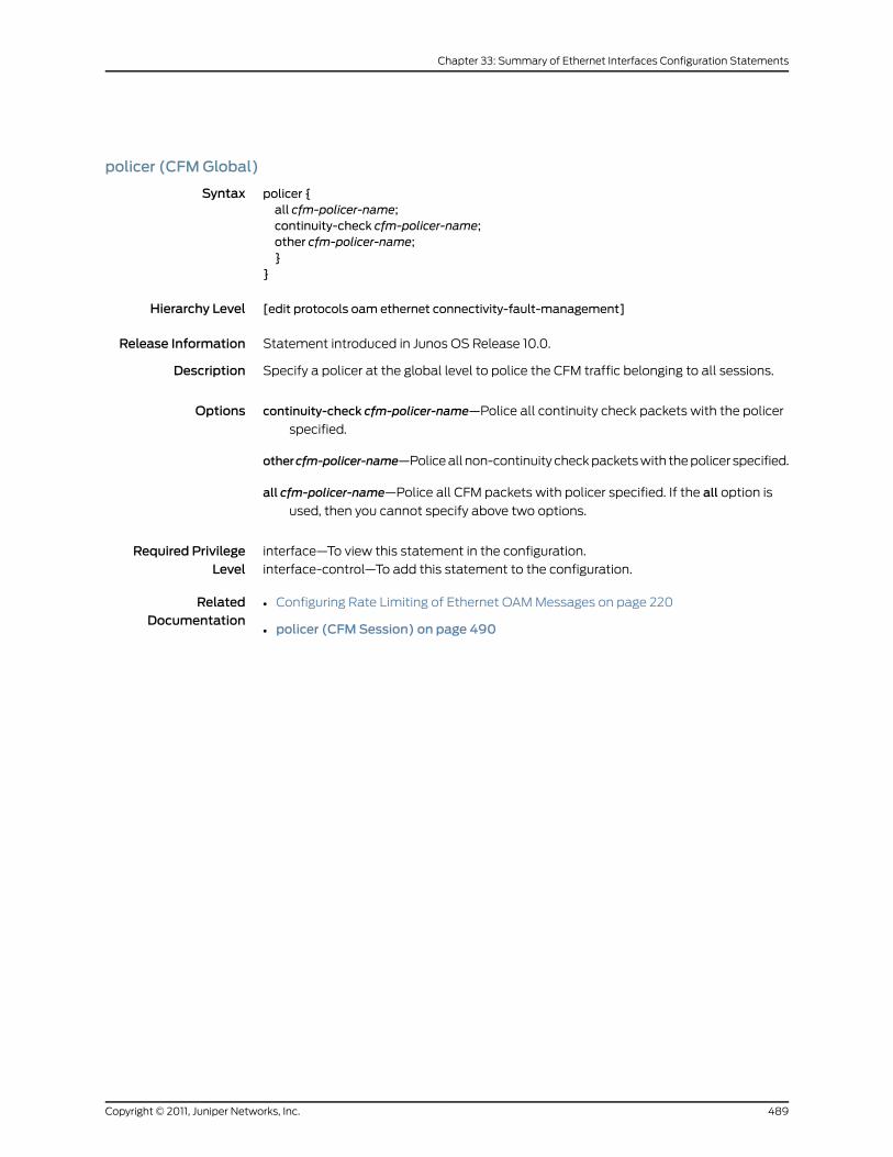
policer (CFMGlobal)
Syntax policer {all cfm-policer-name;continuity-check cfm-policer-name;other cfm-policer-name;}
}
Hierarchy Level [edit protocols oam ethernet connectivity-fault-management]
Release Information Statement introduced in Junos OS Release 10.0.
Description Specify a policer at the global level to police the CFM traffic belonging to all sessions.
Options continuity-check cfm-policer-name—Police all continuity check packets with the policer
specified.
othercfm-policer-name—Police all non-continuity check packets with the policer specified.
all cfm-policer-name—Police all CFM packets with policer specified. If the all option is
used, then you cannot specify above two options.
Required PrivilegeLevel
interface—To view this statement in the configuration.
interface-control—To add this statement to the configuration.
RelatedDocumentation
• Configuring Rate Limiting of Ethernet OAM Messages on page 220
• policer (CFMSession) on page 490
489Copyright © 2011, Juniper Networks, Inc.
Chapter 33: Summary of Ethernet Interfaces Configuration Statements

policer (CFMSession)
Syntax policer {all cfm-policer-name;continuity-check cfm-policer-name;other cfm-policer-name;}
}
Hierarchy Level [edit protocols oam ethernet connectivity-fault-managementmaintenance-domain namelevel numbermaintenance-association name]
Release Information Statement introduced in Junos OS Release 10.0.
Description Specify a separate policer to rate-limit packets specific to that session.
Options • continuity-check cfm-policer-name—Police continuity check packets belonging to this
session.
other cfm-policer-name—Police all non-continuity check packets belonging to this
session.
all cfm-policer-name—Police all CFM packets belonging to this session. If the all option
is used, then you cannot specify the above two options.
Required PrivilegeLevel
interface—To view this statement in the configuration.
interface-control—To add this statement to the configuration.
RelatedDocumentation
• Configuring Rate Limiting of Ethernet OAM Messages on page 220
• policer (CFMGlobal) on page 489
Copyright © 2011, Juniper Networks, Inc.490
Junos®
OS 11.4 Ethernet Interfaces Configuration Guide
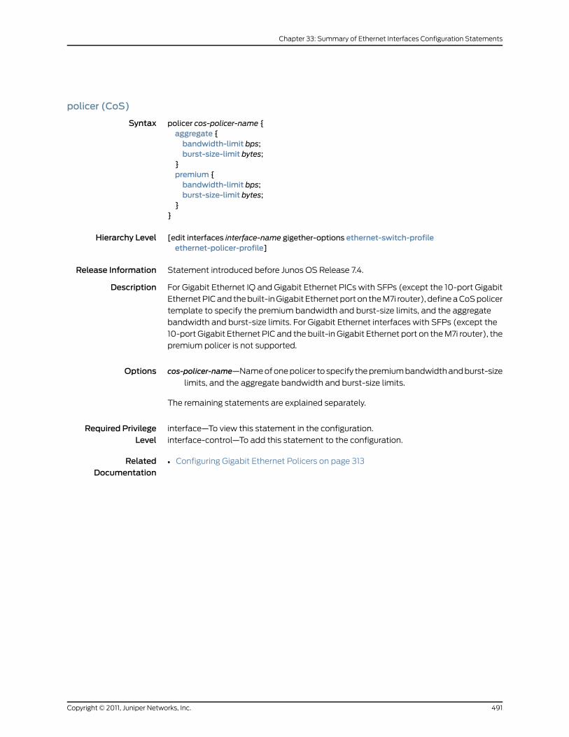
policer (CoS)
Syntax policer cos-policer-name {aggregate {bandwidth-limit bps;burst-size-limit bytes;
}premium {bandwidth-limit bps;burst-size-limit bytes;
}}
Hierarchy Level [edit interfaces interface-name gigether-options ethernet-switch-profileethernet-policer-profile]
Release Information Statement introduced before Junos OS Release 7.4.
Description For Gigabit Ethernet IQ and Gigabit Ethernet PICs with SFPs (except the 10-port Gigabit
Ethernet PIC and the built-in Gigabit Ethernet port on the M7i router), define a CoS policer
template to specify the premium bandwidth and burst-size limits, and the aggregate
bandwidth and burst-size limits. For Gigabit Ethernet interfaces with SFPs (except the
10-port Gigabit Ethernet PIC and the built-in Gigabit Ethernet port on the M7i router), the
premium policer is not supported.
Options cos-policer-name—Name of one policer to specify the premium bandwidth and burst-size
limits, and the aggregate bandwidth and burst-size limits.
The remaining statements are explained separately.
Required PrivilegeLevel
interface—To view this statement in the configuration.
interface-control—To add this statement to the configuration.
RelatedDocumentation
• Configuring Gigabit Ethernet Policers on page 313
491Copyright © 2011, Juniper Networks, Inc.
Chapter 33: Summary of Ethernet Interfaces Configuration Statements
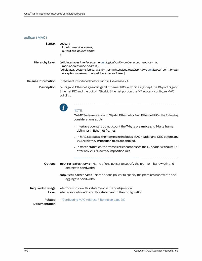
policer (MAC)
Syntax policer {input cos-policer-name;output cos-policer-name;
}
Hierarchy Level [edit interfaces interface-name unit logical-unit-number accept-source-macmac-addressmac-address],
[edit logical-systems logical-system-name interfaces interface-nameunit logical-unit-numberaccept-source-macmac-addressmac-address]
Release Information Statement introduced before Junos OS Release 7.4.
Description For Gigabit Ethernet IQ and Gigabit Ethernet PICs with SFPs (except the 10-port Gigabit
Ethernet PIC and the built-in Gigabit Ethernet port on the M7i router), configure MAC
policing.
NOTE:
OnMXSeries routerswithGigabitEthernetorFastEthernetPICs, the followingconsiderations apply:
• Interface counters do not count the 7-byte preamble and 1-byte framedelimiter in Ethernet frames.
• In MAC statistics, the frame size includesMAC header and CRC before anyVLAN rewrite/imposition rules are applied.
• In traffic statistics, the framesizeencompasses theL2headerwithoutCRCafter any VLAN rewrite/imposition rule.
Options input cos-policer-name—Name of one policer to specify the premium bandwidth and
aggregate bandwidth.
output cos-policer-name—Name of one policer to specify the premium bandwidth and
aggregate bandwidth.
Required PrivilegeLevel
interface—To view this statement in the configuration.
interface-control—To add this statement to the configuration.
RelatedDocumentation
• Configuring MAC Address Filtering on page 317
Copyright © 2011, Juniper Networks, Inc.492
Junos®
OS 11.4 Ethernet Interfaces Configuration Guide

pop
Syntax pop;
Hierarchy Level [edit interfaces interface-name unit logical-unit-number input-vlan-map],[edit interfaces interface-name unit logical-unit-number output-vlan-map],[edit logical-systems logical-system-name interfaces interface-nameunit logical-unit-numberinput-vlan-map],
[edit logical-systems logical-system-name interfaces interface-nameunit logical-unit-numberoutput-vlan-map]
Release Information Statement introduced before Junos OS Release 7.4.
Description For Gigabit Ethernet IQ and 10-Gigabit Ethernet IQ2 and IQ2-E interfaces, 10-Gigabit
Ethernet LAN/WAN PIC, and aggregated Ethernet interfaces using Gigabit Ethernet IQ
interfaces, specify the VLAN rewrite operation to remove a VLAN tag from the top of the
VLAN tag stack. The outer VLAN tag of the frame is removed.
Required PrivilegeLevel
interface—To view this statement in the configuration.
interface-control—To add this statement to the configuration.
RelatedDocumentation
• Removing a VLAN Tag on page 135
pop-pop
Syntax pop-pop;
Hierarchy Level [edit interfaces interface-name unit logical-unit-number input-vlan-map],[edit interfaces interface-name unit logical-unit-number output-vlan-map],[edit logical-systems logical-system-name interfaces interface-nameunit logical-unit-numberinput-vlan-map],
[edit logical-systems logical-system-name interfaces interface-nameunit logical-unit-numberoutput-vlan-map]
Release Information Statement introduced in Junos OS Release 8.1.
Description For Gigabit Ethernet IQ, IQ2 and IQ2-E interfaces, 10-Gigabit Ethernet LAN/WAN PIC,
and for aggregated Ethernet interfaces using Gigabit Ethernet IQ2 and IQ2-E or 10-Gigabit
Ethernet PICs on MX Series routers, specify the VLAN rewrite operation to remove both
the outer and inner VLAN tags of the frame.
Required PrivilegeLevel
interface—To view this statement in the configuration.
interface-control—To add this statement to the configuration.
RelatedDocumentation
• Removing the Outer and Inner VLAN Tags on page 135
493Copyright © 2011, Juniper Networks, Inc.
Chapter 33: Summary of Ethernet Interfaces Configuration Statements
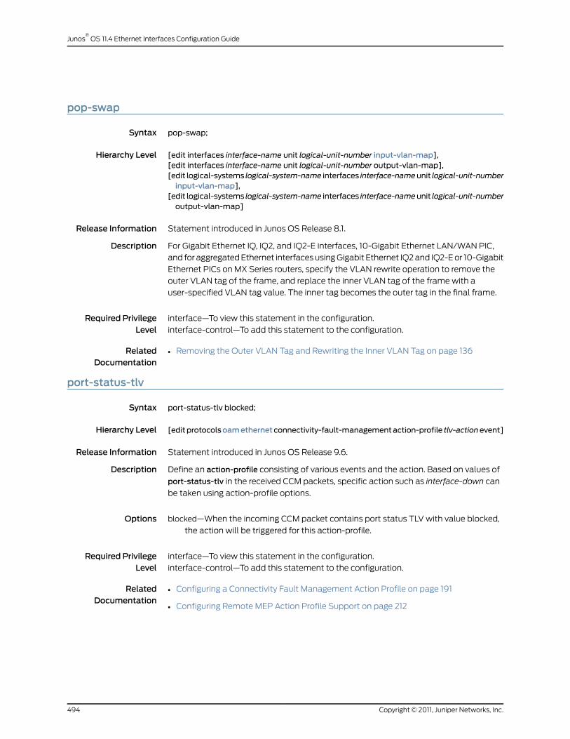
pop-swap
Syntax pop-swap;
Hierarchy Level [edit interfaces interface-name unit logical-unit-number input-vlan-map],[edit interfaces interface-name unit logical-unit-number output-vlan-map],[edit logical-systems logical-system-name interfaces interface-nameunit logical-unit-numberinput-vlan-map],
[edit logical-systems logical-system-name interfaces interface-nameunit logical-unit-numberoutput-vlan-map]
Release Information Statement introduced in Junos OS Release 8.1.
Description For Gigabit Ethernet IQ, IQ2, and IQ2-E interfaces, 10-Gigabit Ethernet LAN/WAN PIC,
and for aggregated Ethernet interfaces using Gigabit Ethernet IQ2 and IQ2-E or 10-Gigabit
Ethernet PICs on MX Series routers, specify the VLAN rewrite operation to remove the
outer VLAN tag of the frame, and replace the inner VLAN tag of the frame with a
user-specified VLAN tag value. The inner tag becomes the outer tag in the final frame.
Required PrivilegeLevel
interface—To view this statement in the configuration.
interface-control—To add this statement to the configuration.
RelatedDocumentation
• Removing the Outer VLAN Tag and Rewriting the Inner VLAN Tag on page 136
port-status-tlv
Syntax port-status-tlv blocked;
Hierarchy Level [editprotocolsoamethernetconnectivity-fault-managementaction-profile tlv-actionevent]
Release Information Statement introduced in Junos OS Release 9.6.
Description Define an action-profile consisting of various events and the action. Based on values of
port-status-tlv in the received CCM packets, specific action such as interface-down can
be taken using action-profile options.
Options blocked—When the incoming CCM packet contains port status TLV with value blocked,
the action will be triggered for this action-profile.
Required PrivilegeLevel
interface—To view this statement in the configuration.
interface-control—To add this statement to the configuration.
RelatedDocumentation
• Configuring a Connectivity Fault Management Action Profile on page 191
• Configuring Remote MEP Action Profile Support on page 212
Copyright © 2011, Juniper Networks, Inc.494
Junos®
OS 11.4 Ethernet Interfaces Configuration Guide

ppp-options
Syntax ppp-options {chap {access-profile name;default-chap-secret name;local-name name;passive;
}compression {acfc;pfc;
}dynamic-profile profile-name;lcp-max-conf-req numberlcp-restart-timermilliseconds;loopback-clear-timer seconds;ncp-max-conf-req numberncp-restart-timermilliseconds;pap {access-profile name;default-pap-password password;local-name name;local-password password;passive;
}}
Hierarchy Level [edit interfaces interface-name],[edit interfaces interface-name unit logical-unit-number],[edit logical-systems logical-system-name interfaces interface-nameunit logical-unit-number]
Release Information Statement introduced before Junos OS Release 7.4.
lcp-restart-timer statement introduced in Junos OS Release 8.1.
ncp-restart-timer statement introduced in Junos OS Release 8.1.
loopback-clear-timer statement introduced in Junos OS Release 8.5.
dynamic-profile statement introduced in Junos OS Release 9.5.
Description On interfaces with PPP encapsulation, configure PPP-specific interface properties.
For ATM2 IQ interfaces only, you can configure CHAP on the logical interface unit if the
logical interface is configured with one of the following PPP over ATM encapsulation
types:
• atm-ppp-llc—PPP over AAL5 LLC encapsulation.
• atm-ppp-vc-mux—PPP over AAL5 multiplex encapsulation.
The remaining statements are explained separately.
Required PrivilegeLevel
interface—To view this statement in the configuration.
interface-control—To add this statement to the configuration.
495Copyright © 2011, Juniper Networks, Inc.
Chapter 33: Summary of Ethernet Interfaces Configuration Statements

RelatedDocumentation
• Configuring the PPP Challenge Handshake Authentication Protocol
pppoe-options
Syntax pppoe-options {access-concentrator name;auto-reconnect seconds;(client | server);service-name name;underlying-interface interface-name;
}
Hierarchy Level [edit interfaces pp0 unit logical-unit-number],[edit logical-systems logical-system-name interfaces pp0 unit logical-unit-number]
Release Information Statement introduced before Junos OS Release 7.4.
client Statement introduced in Junos OS Release 8.5.
server Statement introduced in Junos OS Release 8.5.
Description For J Series Services Routers, M120 Multiservice Edge Routers, M320 Multiservice Edge
Service Routers, and MX Series Universal Edge Routers with PPP over Ethernet interfaces,
configure PPP over Ethernet-specific interface properties.
The remaining statements are explained separately.
Required PrivilegeLevel
interface—To view this statement in the configuration.
interface-control—To add this statement to the configuration.
RelatedDocumentation
• Configuring a PPPoE Interface on page 383
Copyright © 2011, Juniper Networks, Inc.496
Junos®
OS 11.4 Ethernet Interfaces Configuration Guide

pppoe-underlying-options (Static and Dynamic Subscribers)
Syntax pppoe-underlying-options {access-concentrator name;dynamic-profile profile-name;duplicate-protection;max-sessions number;max-sessions-vsa-ignore;service-name-table table-name;short-cycle-protection <lockout-time-minminimum-seconds lockout-time-maxmaximum-seconds>;
}
Hierarchy Level [edit interfaces interface-name unit logical-unit-number],[edit logical-systems logical-system-name interfaces interface-nameunit logical-unit-number]
Release Information Statement introduced in Junos OS Release 10.0.
Description Configure PPPoE-specific interface properties for the underlying interface on which the
router creates a static or dynamic PPPoE logical interface. The underlying interface must
be configured with PPPoE (ppp-over-ether) encapsulation.
The remaining statements are explained separately.
Required PrivilegeLevel
interface—To view this statement in the configuration.
interface-control—To add this statement to the configuration.
RelatedDocumentation
• Configuring PPPoE on page 380 (for static interfaces)
• Configuring an Underlying Interface for Dynamic PPPoE Subscriber Interfaces
• Assigning a Service Name Table to a PPPoE Underlying Interface on page 396
497Copyright © 2011, Juniper Networks, Inc.
Chapter 33: Summary of Ethernet Interfaces Configuration Statements
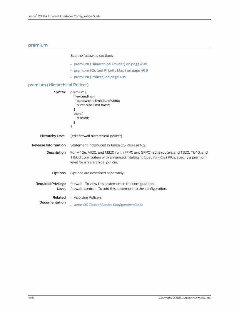
premium
See the following sections:
• premium (Hierarchical Policer) on page 498
• premium (Output Priority Map) on page 499
• premium (Policer) on page 499
premium (Hierarchical Policer)
Syntax premium {if-exceeding {bandwidth-limit bandwidth;burst-size-limit burst;
}then {discard;
}}
Hierarchy Level [edit firewall hierarchical-policer]
Release Information Statement introduced in Junos OS Release 9.5.
Description For M40e, M120, and M320 (with FFPC and SFPC) edge routers and T320, T640, and
T1600 core routers with Enhanced Intelligent Queuing (IQE) PICs, specify a premium
level for a hierarchical policer.
Options Options are described separately.
Required PrivilegeLevel
firewall—To view this statement in the configuration.
firewall-control—To add this statement to the configuration.
RelatedDocumentation
• Applying Policers
• Junos OS Class of Service Configuration Guide
Copyright © 2011, Juniper Networks, Inc.498
Junos®
OS 11.4 Ethernet Interfaces Configuration Guide
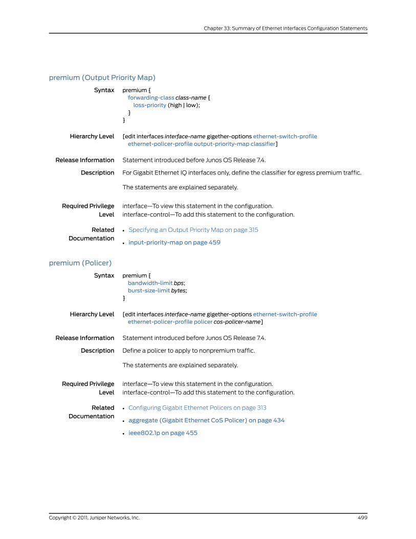
premium (Output Priority Map)
Syntax premium {forwarding-class class-name {loss-priority (high | low);
}}
Hierarchy Level [edit interfaces interface-name gigether-options ethernet-switch-profileethernet-policer-profile output-priority-map classifier]
Release Information Statement introduced before Junos OS Release 7.4.
Description For Gigabit Ethernet IQ interfaces only, define the classifier for egress premium traffic.
The statements are explained separately.
Required PrivilegeLevel
interface—To view this statement in the configuration.
interface-control—To add this statement to the configuration.
RelatedDocumentation
• Specifying an Output Priority Map on page 315
• input-priority-map on page 459
premium (Policer)
Syntax premium {bandwidth-limit bps;burst-size-limit bytes;
}
Hierarchy Level [edit interfaces interface-name gigether-options ethernet-switch-profileethernet-policer-profile policer cos-policer-name]
Release Information Statement introduced before Junos OS Release 7.4.
Description Define a policer to apply to nonpremium traffic.
The statements are explained separately.
Required PrivilegeLevel
interface—To view this statement in the configuration.
interface-control—To add this statement to the configuration.
RelatedDocumentation
• Configuring Gigabit Ethernet Policers on page 313
• aggregate (Gigabit Ethernet CoS Policer) on page 434
• ieee802.1p on page 455
499Copyright © 2011, Juniper Networks, Inc.
Chapter 33: Summary of Ethernet Interfaces Configuration Statements

protection-group
Syntax protection-group {ethernet-ring ring-name (node-idmac-address;ring-protection-link-owner;east-interface {control-channel channel-name {ring-protection-link-end;
}west-interface {node-idmac-address;control-channel channel-name {ring-protection-link-end;
}data-channel {vlan number;
}guard-interval number;restore-interval number;
}}
Hierarchy Level [edit protocols]
Release Information Statement introduced in Junos OS Release 9.4.
Description Configure Ethernet ring protection switching.
The statements are explained separately.
Required PrivilegeLevel
interface—To view this statement in the configuration.
interface-control—To add this statement to the configuration.
RelatedDocumentation
• Ethernet Ring Protection Switching Overview on page 413
• Ethernet Ring Protection Using Ring Instances for Load Balancing
• Example: Configuring Load Balancing Within Ethernet Ring Protection for MX Series
Routers
Copyright © 2011, Juniper Networks, Inc.500
Junos®
OS 11.4 Ethernet Interfaces Configuration Guide

protocol-down
Syntax protocol-down;
Hierarchy Level [edit protocols oam ethernet link-fault-management action-profile event]
Release Information Statement introduced in Junos OS Release 8.5.
Description Upper layer indication of protocol down event. When the protocol-down statement is
included, the protocol down event triggers the action specified under theaction statement.
Required PrivilegeLevel
interface—To view this statement in the configuration.
interface-control—To add this statement to the configuration.
RelatedDocumentation
• Configuring an OAM Action Profile on page 296
ptopo-configuration-maximum-hold-time
Syntax ptopo-configuration-maximum-hold-time seconds;
Hierarchy Level [edit protocols lldp],[edit routing-instances routing-instance-name protocols lldp]
Release Information Statement introduced in Junos OS Release 9.6.
Description (MX Series and T Series routers only) Configure a time to maintain dynamic topology
entries.
Options seconds—Time to maintain interval dynamic topology entries.
Default: 300
Range: 1 through 2147483647
Required PrivilegeLevel
routing—To view this statement in the configuration.
routing-control—To add this statement to the configuration.
RelatedDocumentation
• Configuring LLDP on page 154
501Copyright © 2011, Juniper Networks, Inc.
Chapter 33: Summary of Ethernet Interfaces Configuration Statements
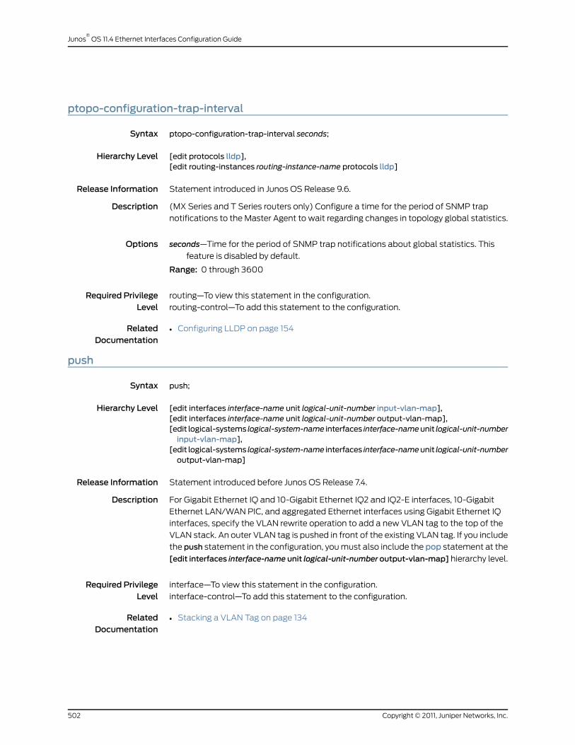
ptopo-configuration-trap-interval
Syntax ptopo-configuration-trap-interval seconds;
Hierarchy Level [edit protocols lldp],[edit routing-instances routing-instance-name protocols lldp]
Release Information Statement introduced in Junos OS Release 9.6.
Description (MX Series and T Series routers only) Configure a time for the period of SNMP trap
notifications to the Master Agent to wait regarding changes in topology global statistics.
Options seconds—Time for the period of SNMP trap notifications about global statistics. This
feature is disabled by default.
Range: 0 through 3600
Required PrivilegeLevel
routing—To view this statement in the configuration.
routing-control—To add this statement to the configuration.
RelatedDocumentation
• Configuring LLDP on page 154
push
Syntax push;
Hierarchy Level [edit interfaces interface-name unit logical-unit-number input-vlan-map],[edit interfaces interface-name unit logical-unit-number output-vlan-map],[edit logical-systems logical-system-name interfaces interface-nameunit logical-unit-numberinput-vlan-map],
[edit logical-systems logical-system-name interfaces interface-nameunit logical-unit-numberoutput-vlan-map]
Release Information Statement introduced before Junos OS Release 7.4.
Description For Gigabit Ethernet IQ and 10-Gigabit Ethernet IQ2 and IQ2-E interfaces, 10-Gigabit
Ethernet LAN/WAN PIC, and aggregated Ethernet interfaces using Gigabit Ethernet IQ
interfaces, specify the VLAN rewrite operation to add a new VLAN tag to the top of the
VLAN stack. An outer VLAN tag is pushed in front of the existing VLAN tag. If you include
the push statement in the configuration, you must also include the pop statement at the
[edit interfaces interface-name unit logical-unit-number output-vlan-map] hierarchy level.
Required PrivilegeLevel
interface—To view this statement in the configuration.
interface-control—To add this statement to the configuration.
RelatedDocumentation
• Stacking a VLAN Tag on page 134
Copyright © 2011, Juniper Networks, Inc.502
Junos®
OS 11.4 Ethernet Interfaces Configuration Guide
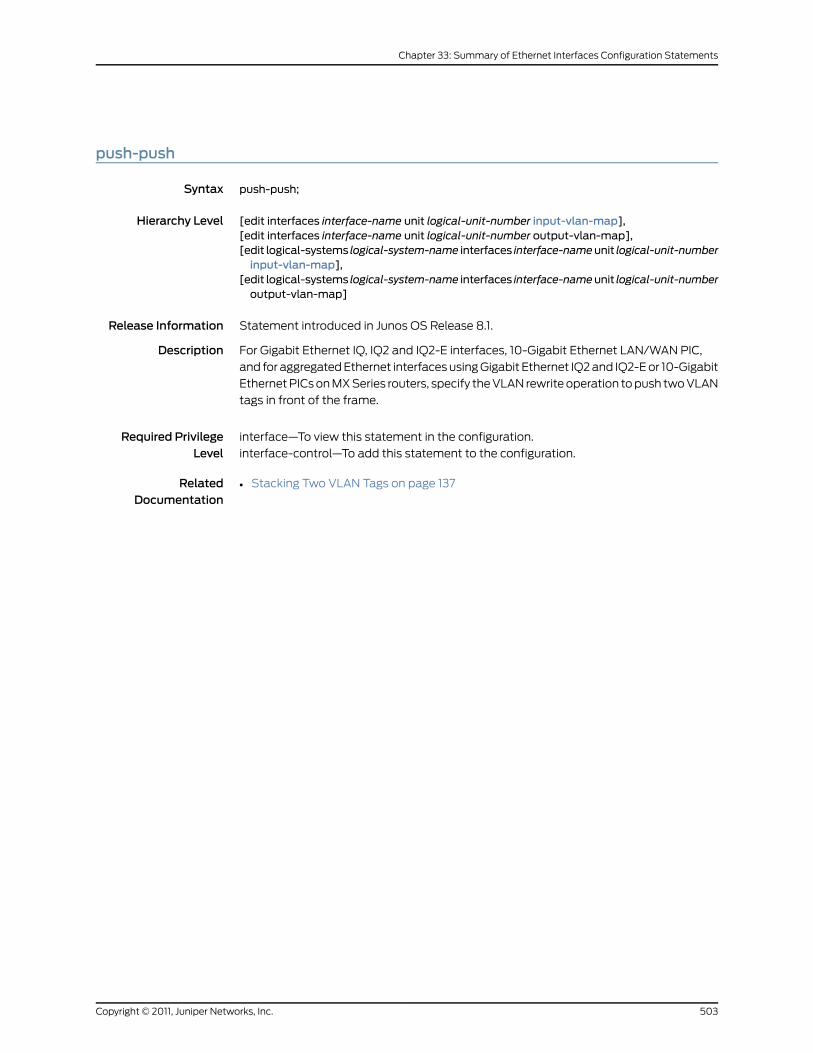
push-push
Syntax push-push;
Hierarchy Level [edit interfaces interface-name unit logical-unit-number input-vlan-map],[edit interfaces interface-name unit logical-unit-number output-vlan-map],[edit logical-systems logical-system-name interfaces interface-nameunit logical-unit-numberinput-vlan-map],
[edit logical-systems logical-system-name interfaces interface-nameunit logical-unit-numberoutput-vlan-map]
Release Information Statement introduced in Junos OS Release 8.1.
Description For Gigabit Ethernet IQ, IQ2 and IQ2-E interfaces, 10-Gigabit Ethernet LAN/WAN PIC,
and for aggregated Ethernet interfaces using Gigabit Ethernet IQ2 and IQ2-E or 10-Gigabit
Ethernet PICs on MX Series routers, specify the VLAN rewrite operation to push two VLAN
tags in front of the frame.
Required PrivilegeLevel
interface—To view this statement in the configuration.
interface-control—To add this statement to the configuration.
RelatedDocumentation
• Stacking Two VLAN Tags on page 137
503Copyright © 2011, Juniper Networks, Inc.
Chapter 33: Summary of Ethernet Interfaces Configuration Statements
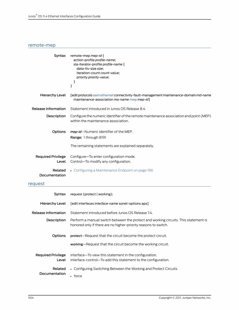
remote-mep
Syntax remote-mepmep-id {action-profile profile-name;sla-iterator-profile profile-name {data-tlv-size size;iteration-count count-value;priority priority-value;
}}
Hierarchy Level [editprotocolsoamethernetconnectivity-fault-managementmaintenance-domainmd-namemaintenance-associationma-namemepmep-id]
Release Information Statement introduced in Junos OS Release 8.4.
Description Configure the numeric identifier of the remote maintenance association end point (MEP)
within the maintenance association.
Options mep-id—Numeric identifier of the MEP.
Range: 1 through 8191
The remaining statements are explained separately.
Required PrivilegeLevel
Configure—To enter configuration mode.
Control—To modify any configuration.
RelatedDocumentation
• Configuring a Maintenance Endpoint on page 186
request
Syntax request (protect | working);
Hierarchy Level [edit interfaces interface-name sonet-options aps]
Release Information Statement introduced before Junos OS Release 7.4.
Description Perform a manual switch between the protect and working circuits. This statement is
honored only if there are no higher-priority reasons to switch.
Options protect—Request that the circuit become the protect circuit.
working—Request that the circuit become the working circuit.
Required PrivilegeLevel
interface—To view this statement in the configuration.
interface-control—To add this statement to the configuration.
RelatedDocumentation
• Configuring Switching Between the Working and Protect Circuits
• force
Copyright © 2011, Juniper Networks, Inc.504
Junos®
OS 11.4 Ethernet Interfaces Configuration Guide

ring-protection-link-end
Syntax ring-protection-link-end;
Hierarchy Level [edit protocols protection-group ethernet-ring ring-name (east-interface |west-interface)]
Release Information Statement introduced in Junos OS Release 9.4.
Description For MS Series routers, specify that the port is one side of a ring protection link (RPL) by
setting the RPL end flag.
Required PrivilegeLevel
interface—To view this statement in the configuration.
interface-control—To add this statement to the configuration.
RelatedDocumentation
• Ethernet Ring Protection Switching Overview on page 413
ring-protection-link-owner
Syntax ring-protection-link-owner;
Hierarchy Level [edit protocols protection-group ethernet-ring ring-name]
Release Information Statement introduced in Junos OS Release 9.4.
Description For MS Series routers, specify the ring protection link (RPL) owner flag in the Ethernet
protection ring. Include this statement only once for each ring (only one node can function
as the RPL owner).
Required PrivilegeLevel
interface—To view this statement in the configuration.
interface-control—To add this statement to the configuration.
RelatedDocumentation
• Ethernet Ring Protection Switching Overview on page 413
505Copyright © 2011, Juniper Networks, Inc.
Chapter 33: Summary of Ethernet Interfaces Configuration Statements
sa-multicast (100-Gigabit Ethernet)
Syntax sa-multicast;
Hierarchy Level [edit chassis fpc slot pic slot forwarding-mode]
Description Configure the 100-Gigabit Ethernet PIC to interoperate with other Juniper Networks
100-Gigabit Ethernet PICs.
See vlan-steering for information on interoperability with 100 gigabit Ethernet interfaces
from other vendors.
Required PrivilegeLevel
interface—To view this statement in the configuration.
interface-control—To add this statement to the configuration.
RelatedDocumentation
• Configuring 100-Gigabit Ethernet PIC VLAN Steering Mode on page 361
• forwarding-mode (100-Gigabit Ethernet) on page 451
• vlan-steering (100-Gigabit Ethernet) on page 536
Copyright © 2011, Juniper Networks, Inc.506
Junos®
OS 11.4 Ethernet Interfaces Configuration Guide
short-cycle-protection (Static and Dynamic Subscribers)
Syntax short-cycle-protection <lockout-time-minminimum-seconds lockout-time-maxmaximum-seconds>;
Hierarchy Level [edit dynamic-profiles profile-name interfaces demux0 unit logical-unit-number familypppoe],
[editdynamic-profilesprofile-name interfaces interface-nameunit logical-unit-number familypppoe],
[edit dynamic-profiles profile-name interfaces interface-name unit logical-unit-numberpppoe-underlying-options],
[edit interfaces demux0 unit logical-unit-number family pppoe][edit interfaces interface-name unit logical-unit-number family pppoe],[edit interfaces interface-name unit logical-unit-number pppoe-underlying-options],[edit logical-systems logical-system-name interfaces interface-nameunit logical-unit-numberfamily pppoe],
[edit logical-systems logical-system-name interfaces interface-nameunit logical-unit-numberpppoe-underlying-options]
Release Information Statement introduced in Junos OS Release 11.4.
Description Configure the router to temporarily prevent (lock out) a failed or short-lived (also known
as short-cycle) PPPoE subscriber session from reconnecting for a default or configurable
period of time. You can optionally override the default lockout time, 1 through 300 seconds
(5 minutes), by specifying the minimum lockout time and maximum lockout time as part
of the short-cycle-protection statement.
Options lockout-time-minminimum-seconds—(Optional) Minimum lockout time for failed or
short-lived PPPoE subscriber sessions. The minimum-seconds value must be less
than or equal to the maximum-seconds value. Setting minimum-seconds and
maximum-seconds to the same value causes the lockout time to become fixed at
that value.
Range: 1 through 86400 (24 hours)
Default: 1
lockout-time-maxmaximum-seconds—(Optional) Maximum lockout time for failed or
short-lived PPPoE subscriber sessions. The maximum-seconds value must be equal
to or greater than the minimum-seconds value. Setting maximum-seconds and
minimum-seconds to the same value causes the lockout time to become fixed at
that value.
Range: 1 through 86400 (24 hours)
Default: 300 (5 minutes)
Required PrivilegeLevel
interface—To view this statement in the configuration.
interface-control—To add this statement to the configuration.
RelatedDocumentation
Configuring Lockout of PPPoE Subscriber Sessions•
• PPPoE Subscriber Session Lockout Overview
• Understanding the Lockout Period for PPPoE Subscriber Session Lockout
507Copyright © 2011, Juniper Networks, Inc.
Chapter 33: Summary of Ethernet Interfaces Configuration Statements

• For information about configuring dynamic PPPoE subscriber interfaces, see the Junos
OS Subscriber Access Configuration Guide
• For information about configuring static PPPoE interfaces, see the Junos OS Ethernet
Interfaces Configuration Guide
source-address-filter
Syntax source-address-filter {mac-address;
}
Hierarchy Level [edit interfaces interface-name aggregated-ether-options],[edit interfaces interface-name fastether-options],[edit interfaces interface-name gigether-options]
Release Information Statement introduced before Junos OS Release 7.4.
Description For aggregated Ethernet, Fast Ethernet, Gigabit Ethernet, Gigabit Ethernet IQ interfaces,
and Gigabit Ethernet PICs with SFPs (except the 10-port Gigabit Ethernet PIC and the
built-in Gigabit Ethernet port on the M7i router), specify the MAC addresses from which
the interface can receive packets. For this statement to have any effect, you must include
the source-filtering statement in the configuration to enable source address filtering. This
statement is not supported on the J Series Services Routers.
Options mac-address—MAC address filter. You can specify the MAC address as nn:nn:nn:nn:nn:nn
or nnnn.nnnn.nnnn, where n is a decimal digit. To specify more than one address,
include multiple mac-address options in the source-address-filter statement.
If you enable the VRRP on a Fast Ethernet or Gigabit Ethernet interface, as described in
“VRRP and VRRP for IPv6 Overview” on page 307, and if you enable MAC source
address filtering on the interface, you must include the virtual MAC address in the
list of source MAC addresses that you specify in the source-address-filter statement.
MAC addresses ranging from 00:00:5e:00:01:00 through 00:00:5e:00:01:ff are
reserved for VRRP, as defined in RFC 3768,VirtualRouterRedundancyProtocol. When
you configure the VRRP group, the group number must be the decimal equivalent
of the last hexadecimal byte of the virtual MAC address.
On untagged Gigabit Ethernet interfaces you should not configure the source-address-filter
statement and theaccept-source-mac statement simultaneously. On tagged Gigabit
Ethernet interfaces you should not configure the source-address-filter statement
and the accept-source-mac statement with an identical MAC address specified in
both filters.
Required PrivilegeLevel
interface—To view this statement in the configuration.
interface-control—To add this statement to the configuration.
RelatedDocumentation
• Enabling Ethernet MAC Address Filtering on page 42
• source-filtering on page 509
Copyright © 2011, Juniper Networks, Inc.508
Junos®
OS 11.4 Ethernet Interfaces Configuration Guide

source-filtering
Syntax (source-filtering | no-source-filtering);
Hierarchy Level [edit interfaces interface-name aggregated-ether-options],[edit interfaces interface-name fastether-options],[edit interfaces interface-name gigether-options]
Release Information Statement introduced before Junos OS Release 7.4.
Description For aggregated Ethernet, Fast Ethernet, Gigabit Ethernet, and Gigabit Ethernet IQ
interfaces only, enable the filtering of MAC source addresses, which blocks all incoming
packets to that interface. To allow the interface to receive packets from specific MAC
addresses, include the source-address-filter statement.
If the remote Ethernet card is changed, the interface is no longer able to receive packets
from the new card because it has a different MAC address.
Default Source address filtering is disabled.
Required PrivilegeLevel
interface—To view this statement in the configuration.
interface-control—To add this statement to the configuration.
RelatedDocumentation
• Enabling Ethernet MAC Address Filtering on page 42
• accept-source-mac
• source-address-filter on page 508
509Copyright © 2011, Juniper Networks, Inc.
Chapter 33: Summary of Ethernet Interfaces Configuration Statements

speed
See the following sections:
• speed (Ethernet) on page 510
• speed (MX Series DPC) on page 511
speed (Ethernet)
Syntax speed (10m | 100m | 1g | auto);
Hierarchy Level [edit interfaces interface-name],[edit interfaces ge-pim/0/0 switch-options switch-port port-number]
Release Information Statement introduced before Junos OS Release 7.4.
Description Configure the interface speed. This statement applies to the management Ethernet
interface (fxp0orem0), Fast Ethernet 12-port and 48-port PICs, the built-in Fast Ethernet
port on the FIC (M7i router), the built-in Ethernet interfaces on J Series Services Routers,
Combo Line Rate DPCs and Tri-Rate Ethernet Copper interfaces on MX Series routers,
and on the Gigabit Ethernet ports on J Series Services Routers with uPIMs installed and
configured for access switching mode. When you configure the Tri-Rate Ethernet copper
interface to operate at 1 Gbps, autonegotiation must be enabled. When you configure
100BASE-FX SFP, you must set the port speed at 100 Mbps.
Options You can specify the speed as either 10m (10 Mbps), 100m (100 Mbps), or on J Series
routers with uPIMs installed and on MX Series routers, 1g (1 Gbps). You can specify
the auto option only on MX Series routers.
Required PrivilegeLevel
interface—To view this statement in the configuration.
interface-control—To add this statement to the configuration.
RelatedDocumentation
• Configuring the Interface Speed
• Configuring the Interface Speed on Ethernet Interfaces on page 49
• Configuring Gigabit Ethernet Autonegotiation on page 325
• Configuring J Series Services Router Switching Interfaces on page 40
Copyright © 2011, Juniper Networks, Inc.510
Junos®
OS 11.4 Ethernet Interfaces Configuration Guide

speed (MX Series DPC)
Syntax speed (auto | 1Gbps | 100Mbps | 10Mbps);
Hierarchy Level [edit interfaces ge-fpc/pic/port]
Release Information Statement introduced in Junos OS Release 9.5.
Description On MX Series routers with Combo Line Rate DPCs and Tri-Rate Copper SFPs you can
set auto negotiation of speed. To specify the auto negotiation speed, use the speed (auto
| 1Gbps| 100Mbps| 10Mbps)statement under the [edit interfacege-/fpc/pic/port]hierarchy
level. The auto option will attempt to automatically match the rate of the connected
interface. To set port speed negotiation to a specific rate, set the port speed to 1Gbps,
100Mbps, or 10Mbps.
NOTE: If the negotiated speed and the interface speed do not match, thelink will not be brought up. Half duplexmode is not supported.
Options You can specify the speed as either auto (autonegotiate), 10Mbps (10 Mbps), 100Mbps
(100 Mbps), or 1Gbps (1 Gbps).
Required PrivilegeLevel
interface—To view this statement in the configuration.
interface-control—To add this statement to the configuration.
RelatedDocumentation
• Configuring Gigabit Ethernet Autonegotiation on page 325
• no-auto-mdix on page 480
511Copyright © 2011, Juniper Networks, Inc.
Chapter 33: Summary of Ethernet Interfaces Configuration Statements
swap
Syntax swap;
Hierarchy Level [edit interfaces interface-name unit logical-unit-number input-vlan-map],[edit interfaces interface-name unit logical-unit-number output-vlan-map],[edit logical-systems logical-system-name interfaces interface-nameunit logical-unit-numberinput-vlan-map],
[edit logical-systems logical-system-name interfaces interface-nameunit logical-unit-numberoutput-vlan-map]
Release Information Statement introduced before Junos OS Release 7.4.
Description For Gigabit Ethernet IQ and 10-Gigabit Ethernet IQ2 and IQ2-E interfaces, 10-Gigabit
Ethernet LAN/WAN PIC, and aggregated Ethernet using Gigabit Ethernet IQ interfaces,
specify the VLAN rewrite operation to replace a VLAN tag. The outer VLAN tag of the
frame is overwritten with the user-specified VLAN tag information.
Required PrivilegeLevel
interface—To view this statement in the configuration.
interface-control—To add this statement to the configuration.
RelatedDocumentation
• Rewriting the VLAN Tag on Tagged Frames on page 138
swap-push
Syntax swap-push;
Hierarchy Level [edit interfaces interface-name unit logical-unit-number input-vlan-map],[edit interfaces interface-name unit logical-unit-number output-vlan-map],[edit logical-systems logical-system-name interfaces interface-nameunit logical-unit-numberinput-vlan-map],
[edit logical-systems logical-system-name interfaces interface-nameunit logical-unit-numberoutput-vlan-map]
Release Information Statement introduced in Junos OS Release 8.1.
Description For Gigabit Ethernet IQ, IQ2 and IQ2-E interfaces, 10-Gigabit Ethernet LAN/WAN PIC,
and for aggregated Ethernet interfaces using Gigabit Ethernet IQ2 and IQ2-E or 10-Gigabit
Ethernet PICs on MX Series routers, specify the VLAN rewrite operation to replace the
outer VLAN tag of the frame with a user-specified VLAN tag value. A user-specified outer
VLAN tag is pushed in front. The outer tag becomes an inner tag in the final frame.
Required PrivilegeLevel
interface—To view this statement in the configuration.
interface-control—To add this statement to the configuration.
RelatedDocumentation
• Rewriting a VLAN Tag and Adding a New Tag on page 142
Copyright © 2011, Juniper Networks, Inc.512
Junos®
OS 11.4 Ethernet Interfaces Configuration Guide

swap-swap
Syntax swap-swap;
Hierarchy Level [edit interfaces interface-name unit logical-unit-number input-vlan-map],[edit interfaces interface-name unit logical-unit-number output-vlan-map],[edit logical-systems logical-system-name interfaces interface-nameunit logical-unit-numberinput-vlan-map],
[edit logical-systems logical-system-name interfaces interface-nameunit logical-unit-numberoutput-vlan-map]
Release Information Statement introduced in Junos OS Release 8.1.
Description For Gigabit Ethernet IQ, IQ2 and IQ2-E interfaces, 10-Gigabit Ethernet LAN/WAN PIC,
and for aggregated Ethernet interfaces using Gigabit Ethernet IQ2 and IQ2-E or 10-Gigabit
Ethernet PICs on MX Series routers, specify the VLAN rewrite operation to replace both
the inner and the outer VLAN tags of the frame with a user-specified VLAN tag value.
Required PrivilegeLevel
interface—To view this statement in the configuration.
interface-control—To add this statement to the configuration.
RelatedDocumentation
• Rewriting the Inner and Outer VLAN Tags on page 142
switch-options
Syntax switch-options {switch-port port-number {(auto-negotiation | no-auto-negotiation);speed (10m | 100m | 1g);link-mode (full-duplex | half-duplex);
}}
Hierarchy Level [edit interfaces ge-pim/0/0]
Release Information Statement introduced in Junos OS Release 8.4.
Description On a J Series Services Router with multiport Gigabit Ethernet uPIMs installed and operating
in access switching mode, only one physical interface is configured for the entire multiport
Gigabit Ethernet uPIM. Configuration of the physical port characteristics is done under
the single physical interface.
Required PrivilegeLevel
interface—To view this statement in the configuration.
interface-control—To add this statement to the configuration.
RelatedDocumentation
• Configuring J Series Services Router Switching Interfaces on page 40
513Copyright © 2011, Juniper Networks, Inc.
Chapter 33: Summary of Ethernet Interfaces Configuration Statements
switch-port
Syntax switch-port port-number {(auto-negotiation | no-auto-negotiation);speed (10m | 100m | 1g);link-mode (full-duplex | half-duplex);
}
Hierarchy Level [edit interfaces ge-pim/0/0 switch-options]
Release Information Statement introduced in Junos OS Release 8.4.
Description On a J Series Services Router with Ethernet uPIMs installed and operating in access
switching mode, configuration of the physical port characteristics, done under the single
physical interface.
Default Autonegotiation is enabled by default. If the link speed and duplex are also configured,
the interfaces use the values configured as the desired values in the negotiation.
Options port-number—Ports are numbered 0 through 5 on the 6-port Gigabit Ethernet uPIM, 0
through 7 on the 8-port Gigabit Ethernet uPIM, and 0 through 15 on the 16-port Gigabit
Ethernet uPIM.
The remaining statements are explained separately.
Required PrivilegeLevel
interface—To view this statement in the configuration.
interface-control—To add this statement to the configuration.
RelatedDocumentation
• Configuring J Series Services Router Switching Interfaces on page 40
Copyright © 2011, Juniper Networks, Inc.514
Junos®
OS 11.4 Ethernet Interfaces Configuration Guide
tag-protocol-id
See the following sections:
• tag-protocol-id (TPIDs Expected to Be Sent or Received) on page 515
• tag-protocol-id (TPID to Rewrite) on page 516
tag-protocol-id (TPIDs Expected to Be Sent or Received)
Syntax tag-protocol-id [ tpids ];
Hierarchy Level [edit interfaces interface-name gigether-options ethernet-switch-profile],[edit interfaces interface-name aggregated-ether-options ethernet-switch-profile]
Release Information Statement introduced before Junos OS Release 7.4.
Description For Gigabit Ethernet IQ and 10-Gigabit Ethernet IQ2 and IQ2-E interfaces, aggregated
Ethernet with Gigabit Ethernet IQ interfaces, and Gigabit Ethernet PICs with SFPs (except
the 10-port Gigabit Ethernet PIC, and the built-in Gigabit Ethernet port on the M7i router),
define the TPIDs expected to be sent or received on a particular VLAN. For each Gigabit
Ethernet port, you can configure up to eight TPIDs using the tag-protocol-id statement;
but only the first four TPIDs are supported on IQ2 and IQ2-E interfaces.
For 10-Gigabit Ethernet LAN/WAN PIC interfaces on T Series routers, only the default
TPID value (0x8100) is supported.
Options tpids—TPIDs to be accepted on the VLAN. Specify TPIDs in hexadecimal.
Required PrivilegeLevel
interface—To view this statement in the configuration.
interface-control—To add this statement to the configuration.
RelatedDocumentation
• Configuring Frames with Particular TPIDs to Be Processed as Tagged Frames on page 129
515Copyright © 2011, Juniper Networks, Inc.
Chapter 33: Summary of Ethernet Interfaces Configuration Statements

tag-protocol-id (TPID to Rewrite)
Syntax tag-protocol-id tpid;
Hierarchy Level [edit interfaces interface-name unit logical-unit-number input-vlan-map],[edit interfaces interface-name unit logical-unit-number output-vlan-map],[edit logical-systems logical-system-name interfaces interface-nameunit logical-unit-numberinput-vlan-map],
[edit logical-systems logical-system-name interfaces interface-nameunit logical-unit-numberoutput-vlan-map]
Release Information Statement introduced before Junos OS Release 7.4.
Description For Gigabit Ethernet IQ and 10-Gigabit Ethernet IQ2 and IQ2-E interfaces only, configure
the outer TPID value. All TPIDs you include in input and output VLAN maps must be
among those you specify at the [edit interfaces interface-name gigether-options
ethernet-switch-profile tag-protocol-id [ tpids ]] hierarchy level.
For 10-Gigabit Ethernet LAN/WAN PIC interfaces on T Series routers, value the default
TPID value (0x8100) is supported.
Default If the tag-protocol-id statement is not configured, the TPID value is 0x8100.
Required PrivilegeLevel
interface—To view this statement in the configuration.
interface-control—To add this statement to the configuration.
RelatedDocumentation
• Configuring Inner and Outer TPIDs and VLAN IDs on page 131
Copyright © 2011, Juniper Networks, Inc.516
Junos®
OS 11.4 Ethernet Interfaces Configuration Guide

traceoptions
Syntax traceoptions {file filename <files number> <sizemaximum-file-size> <world-readable |no-world-readable>;
flag flag <disable>;}
Hierarchy Level [edit protocols lldp],[edit routing-instances routing-instance-name protocols lldp]
Release Information Statement introduced in Junos OS Release 9.6.
Description Set LLDP protocol-level tracing options.
Default The default LLDP protocol-level trace options are inherited from the global traceoptions
statement.
Options disable—(Optional) Disable the tracing operation. One use of this option is to disable a
single operation when you have defined a broad group of tracing operations, such
as all.
file filename—Name of the file to receive the output of the tracing operation. Enclose the
name in quotation marks. We recommend that you place spanning-tree protocol
tracing output in the file /var/log/stp-log.
files number—(Optional) Maximum number of trace files. When a trace file named
trace-file reaches its maximum size, it is renamed trace-file.0, then trace-file.1, and
so on, until the maximum number of trace files is reached. Then, the oldest trace file
is overwritten.
If you specify a maximum number of files, you must also specify a maximum file size with
the size option.
Range: 2 through 1000 files
Default: 1 trace file only
flag—Tracing operation to perform. To specify more than one tracing operation, include
multiple flag statements. The following are the LLDP-specific tracing options:
• all—Trace all operations.
• config—Log configuration events.
• interface—Trace interface update events.
• protocol—Trace protocol information.
• rtsock—Trace socket events.
• vlan—Trace vlan update events.
517Copyright © 2011, Juniper Networks, Inc.
Chapter 33: Summary of Ethernet Interfaces Configuration Statements

The following are the global tracing options:
• all—All tracing operations.
• config-internal—Trace configuration internals.
• general—Trace general events.
• normal—All normal events. This is the default. If you do not specify this option, only
unusual or abnormal operations are traced.
• parse—Trace configuration parsing.
• policy—Trace policy operations and actions.
• regex-parse—Trace regular-expression parsing.
• route—Trace routing table changes.
• state—Trace state transitions.
• task—Trace protocol task processing.
• timer—Trace protocol task timer processing.
no-world-readable—(Optional) Prevent any user from reading the log file. This is the
default. If you do not include this option, tracing output is appended to an existing
trace file.
sizemaximum-file-size—(Optional) Maximum size of each trace file, in kilobytes (KB)
or megabytes (MB). When a trace file named trace-file reaches this size, it is renamed
trace-file.0. When the trace-fileagain reaches its maximum size, trace-file.0 is renamed
trace-file.1 and trace-file is renamed trace-file.0. This renaming scheme continues
until the maximum number of trace files is reached. Then the oldest trace file is
overwritten.
If you specify a maximum file size, you must also specify a maximum number of trace
files with the files option.
Syntax: xk to specify KB, xm to specify MB, or xg to specify GB
Range: 10 KB through the maximum file size supported on your system
Default: 1 MB
world-readable—(Optional) Allow any user to read the log file.
Required PrivilegeLevel
routing—To view this statement in the configuration.
routing-control—To add this statement to the configuration.
RelatedDocumentation
• Tracing LLDP Operations on page 156
Copyright © 2011, Juniper Networks, Inc.518
Junos®
OS 11.4 Ethernet Interfaces Configuration Guide

transmit-delay
Syntax transmit-delay seconds;
Hierarchy Level [edit protocols lldp],[edit routing-instances routing-instance-name protocols lldp]
Release Information Statement introduced in Junos OS Release 9.6.
Description (MX Series and T Series routers only) Configure a delay between two successive LLDP
advertisements.
Options seconds—Delay between two successive LLDP advertisements.
Default: 2
Range: 1 through 8192
Required PrivilegeLevel
routing—To view this statement in the configuration.
routing-control—To add this statement to the configuration.
RelatedDocumentation
• Configuring LLDP on page 154
519Copyright © 2011, Juniper Networks, Inc.
Chapter 33: Summary of Ethernet Interfaces Configuration Statements

unit
Syntax unit logical-unit-number {accept-source-mac {mac-addressmac-address {policer {input cos-policer-name;output cos-policer-name;
}}
}accounting-profile name;advisory-options (downstream-rate | upstream-rate) rate;allow-any-vci;atm-scheduler-map (map-name | default);backup-options {interface interface-name;
}bandwidth rate;cell-bundle-size cells;clear-dont-fragment-bit;compression {rtp {maximum-contexts number <force>;f-max-period number;queues [ queue-numbers ];port {minimum port-number;maximum port-number;
}}
}compression-device interface-name;copy-tos-to-outer-ip-header;demux-destination family;demux-source family;demux-options {underlying-interface interface-name;
}description text;interface {l2tp-interface-id name;(dedicated | shared);
}dialer-options {activation-delay seconds;callback;callback-wait-period time;deactivation-delay seconds;dial-string [ dial-string-numbers ];idle-timeout seconds;incoming-map {caller caller-id) | accept-all;initial-route-check seconds;
Copyright © 2011, Juniper Networks, Inc.520
Junos®
OS 11.4 Ethernet Interfaces Configuration Guide

load-interval seconds;load-threshold percent;pool pool-name;redial-delay time;watch-list {[ routes ];
}}
}disable;disable-mlppp-inner-ppp-pfc;dlci dlci-identifier;drop-timeoutmilliseconds;dynamic-call-admission-control {activation-priority priority;bearer-bandwidth-limit kilobits-per-second;
}encapsulation type;epd-threshold cells plp1 cells;family family-name {... the family subhierarchy appears after the main [edit interfaces interface-name unitlogical-unit-number] hierarchy ...
}fragment-threshold bytes;inner-vlan-id-range start start-id end end-id;input-vlan-map {(pop | pop-pop | pop-swap | push | push-push | swap |swap-push | swap-swap);inner-tag-protocol-id tpid;inner-vlan-id number;tag-protocol-id tpid;vlan-id number;
}interleave-fragments;inverse-arp;layer2-policer {input-policer policer-name;input-three-color policer-name;output-policer policer-name;output-three-color policer-name;
}link-layer-overhead percent;minimum-links number;mrru bytes;multicast-dlci dlci-identifier;multicast-vci vpi-identifier.vci-identifier;multilink-max-classes number;multipoint;oam-liveness {up-count cells;down-count cells;
}oam-period (disable | seconds);output-vlan-map {(pop | pop-pop | pop-swap | push | push-push | swap |swap-push | swap-swap);
521Copyright © 2011, Juniper Networks, Inc.
Chapter 33: Summary of Ethernet Interfaces Configuration Statements
inner-tag-protocol-id tpid;inner-vlan-id number;tag-protocol-id tpid;vlan-id number;
}passive-monitor-mode;peer-unit unit-number;plp-to-clp;point-to-point;ppp-options {chap {access-profile name;default-chap-secret name;local-name name;passive;
}compression {acfc;pfc;
}dynamic-profile profile-name;lcp-restart-timermilliseconds;loopback-clear-timer seconds;ncp-restart-timermilliseconds;pap {access-profile name;default-pap-password password;local-name name;local-password password;passive;
}}pppoe-options {access-concentrator name;auto-reconnect seconds;(client | server);service-name name;underlying-interface interface-name;
}pppoe-underlying-options {access-concentrator name;dynamic-profile profile-name;max-sessions number;
}proxy-arp;service-domain (inside | outside);shaping {(cbr rate | rtvbr peak rate sustained rate burst length | vbr peak rate sustained rate burstlength);
queue-length number;}short-sequence;targeted-distribution;transmit-weight number;(traps | no-traps);trunk-bandwidth rate;
Copyright © 2011, Juniper Networks, Inc.522
Junos®
OS 11.4 Ethernet Interfaces Configuration Guide

trunk-id number;tunnel {backup-destination address;destination address;key number;routing-instance {destination routing-instance-name;
}source source-address;ttl number;
}vci vpi-identifier.vci-identifier;vci-range start start-vci end end-vci;vpi vpi-identifier;vlan-id number;vlan-id-range number-number;vlan-tags inner tpid.vlan-id outer tpid.vlan-id;family family {accounting {destination-class-usage;source-class-usage {(input | output | input output);
}}access-concentrator name;address address {... the address subhierarchy appears after the main [edit interfaces interface-name unitlogical-unit-number family family-name] hierarchy ...
}bridge-domain-type (bvlan | svlan);bundle interface-name;core-facing;demux-destination {destination-prefix;
}demux-source {source-prefix;
}duplicate-protection;dynamic-profile profile-name;filter {group filter-group-number;input filter-name;input-list [ filter-names ];output filter-name;output-list [ filter-names ];
}interface-mode (access | trunk);ipsec-sa sa-name;isid-list all-service-groups;keep-address-and-control;mac-validate (loose | strict);max-sessions number;mtu bytes;multicast-only;no-redirects;
523Copyright © 2011, Juniper Networks, Inc.
Chapter 33: Summary of Ethernet Interfaces Configuration Statements

policer {arp policer-template-name;input policer-template-name;output policer-template-name;
}primary;protocols [inet isompls];proxy inet-address address;receive-options-packets;receive-ttl-exceeded;remote (inet-address address | mac-address address);rpf-check {fail-filter filter-namemode loose;
}sampling {input;output;
}service {input {post-service-filter filter-name;service-set service-set-name <service-filter filter-name>;
}output {service-set service-set-name <service-filter filter-name>;
}}service-name-table table-name(translate-discard-eligible | no-translate-discard-eligible);(translate-fecn-and-becn | no-translate-fecn-and-becn);translate-plp-control-word-de;unnumbered-address interface-namedestinationaddressdestination-profileprofile-name;vlan-id number;vlan-id-list [number number-number];address address {arp ip-address (mac | multicast-mac)mac-address <publish>;broadcast address;destination address;destination-profile name;eui-64;master-only;multipoint-destination address {dlci dlci-identifier;epd-threshold cells <plp1 cells>;inverse-arp;oam-liveness {up-count cells;down-count cells;
}oam-period (disable | seconds);shaping {(cbr rate | rtvbr burst length peak rate sustained rate | vbr burst length peak ratesustained rate);
queue-length number;}
Copyright © 2011, Juniper Networks, Inc.524
Junos®
OS 11.4 Ethernet Interfaces Configuration Guide
vci vpi-identifier.vci-identifier;}preferred;primary;(vrrp-group | vrrp-inet6-group) group-number {(accept-data | no-accept-data);advertise–interval seconds;authentication-type authentication;authentication-key key;fast-intervalmilliseconds;(preempt | no-preempt) {hold-time seconds;
}priority number;track {interface interface-name {bandwidth-threshold bits-per-second priority-cost number;
}priority-hold-time seconds;route ip-address/prefix-length routing-instance instance-name priority-cost cost;
}virtual-address [ addresses ];virtual-link-local-address ipv6–address;vrrp-inherit-from {active-interface interface-name;active-group group-number;
}}
}}
}
Hierarchy Level [edit interfaces interface-name],[edit logical-systems logical-system-name interfaces interface-name],[edit interfaces interface-set interface-set-name interface interface-name]
Release Information Statement introduced before Junos OS Release 7.4.
Description Configure a logical interface on the physical device. You must configure a logical interface
to be able to use the physical device.
Options logical-unit-number—Number of the logical unit.
Range: 0 through 1,073,741,823 for demux and PPPoE static interfaces only. 0 through
16,385 for all other static interface types.
The remaining statements are explained separately.
Required PrivilegeLevel
interface—To view this statement in the configuration.
interface-control—To add this statement to the configuration.
525Copyright © 2011, Juniper Networks, Inc.
Chapter 33: Summary of Ethernet Interfaces Configuration Statements

RelatedDocumentation
• Configuring Logical Interface Properties
• Example: Configuring E-LINE and E-LAN Services for a PBB Network on MX Series
Routers
• Junos OS Services Interfaces Configuration Guide
Copyright © 2011, Juniper Networks, Inc.526
Junos®
OS 11.4 Ethernet Interfaces Configuration Guide

vlan-id
See the following sections:
• vlan-id (Logical Port in Bridge Domain) on page 527
• vlan-id (Outer VLAN ID) on page 528
• vlan-id (VLAN ID to Be Bound to a Logical Interface) on page 528
• vlan-id (VLAN ID to Rewrite) on page 529
vlan-id (Logical Port in Bridge Domain)
Syntax vlan-id number;
Hierarchy Level [edit interfaces interface-name unit logical-unit-number family bridge],[edit logical-systems logical-system-name interfaces interface-nameunit logical-unit-numberfamily bridge]
Release Information Statement introduced in Junos OS Release 9.2.
Description The VLAN ID configured on the logical port. Received packets with no VLAN tags are
forwarded within the bridge domain with the matching VLAN ID.
Options number—The VLAN ID.
Range: 1 through 4095
Required PrivilegeLevel
interface—To view this statement in the configuration.
interface-control—To add this statement to the configuration.
RelatedDocumentation
• Configuring a Logical Interface for Access Mode on page 75
527Copyright © 2011, Juniper Networks, Inc.
Chapter 33: Summary of Ethernet Interfaces Configuration Statements
vlan-id (Outer VLAN ID)
Syntax vlan-id outer-vlan-id;
Hierarchy Level [edit interfaces interface-name unit logical-unit-number],[edit logical-systems logical-system-name interfaces interface-nameunit logical-unit-number]
Release Information Statement introduced in Junos OS Release 9.0.
Description The outer VLAN ID to be used in ATM-to-Ethernet interworking cross-connects. Outer
VLAN IDs are converted to the ATM VPI. The outer VLAN ID must match the VPI value
configured. The allowable VPI range is 0 to 255. Do not configure the outer VLAN ID to
be greater than 255.
Options outer-vlan-id—Outer VLAN ID number.
Range: 0 through 4094
Required PrivilegeLevel
interface—To view this statement in the configuration.
interface-control—To add this statement to the configuration.
RelatedDocumentation
• Configuring ATM-to-Ethernet Interworking
vlan-id (VLAN ID to Be Bound to a Logical Interface)
Syntax vlan-id number;
Hierarchy Level [edit interfaces interface-name unit logical-unit-number],[edit logical-systems logical-system-name interfaces interface-nameunit logical-unit-number]
Release Information Statement introduced before Junos OS Release 7.4.
Description For Fast Ethernet, Gigabit Ethernet, and Aggregated Ethernet interfaces only, bind a
802.1Q VLAN tag ID to a logical interface.
Options number—A valid VLAN identifier.
Range: For aggregated Ethernet, 4-port, 8-port, and 12-port Fast Ethernet PICs, and for
management and internal Ethernet interfaces, 1 through 1023.
For 48-port Fast Ethernet and Gigabit Ethernet PICs, 1 through 4094.
VLAN ID 0 is reserved for tagging the priority of frames.
Required PrivilegeLevel
interface—To view this statement in the configuration.
interface-control—To add this statement to the configuration.
RelatedDocumentation
• Configuring Mixed Tagging on page 57
Copyright © 2011, Juniper Networks, Inc.528
Junos®
OS 11.4 Ethernet Interfaces Configuration Guide
vlan-id (VLAN ID to Rewrite)
Syntax vlan-id number;
Hierarchy Level [edit interfaces interface-name unit logical-unit-number input-vlan-map],[edit interfaces interface-name unit logical-unit-number output-vlan-map],[edit logical-systems logical-system-name interfaces interface-nameunit logical-unit-numberinput-vlan-map],
[edit logical-systems logical-system-name interfaces interface-nameunit logical-unit-numberoutput-vlan-map]
Release Information Statement introduced before Junos OS Release 7.4.
Description For Gigabit Ethernet IQ and 10-Gigabit Ethernet IQ2, 10-Gigabit Ethernet LAN/WAN PIC,
and IQ2-E interfaces and aggregated Ethernet using Gigabit Ethernet IQ interfaces, specify
the line VLAN identifiers to be rewritten at the input or output interface.
You cannot include thevlan-idstatement with the swapstatement, swap-pushstatement,
push-push statement, or push-swap statement at the [edit interfaces interface-nameunit
logical-unit-number output-vlan-map] hierarchy level. If you include any of those
statements in the output VLAN map, the VLAN ID in the outgoing frame is rewritten to
the vlan-id statement that you include at the [edit interfaces interface-name unit
logical-unit-number] hierarchy level.
Required PrivilegeLevel
interface—To view this statement in the configuration.
interface-control—To add this statement to the configuration.
RelatedDocumentation
• Rewriting the VLAN Tag on Tagged Frames on page 138
• Binding VLAN IDs to Logical Interfaces on page 59
529Copyright © 2011, Juniper Networks, Inc.
Chapter 33: Summary of Ethernet Interfaces Configuration Statements

vlan-id-list
See the following sections:
• vlan-id-list (Ethernet VLAN Circuit) on page 531
• vlan-id-list (Interface in Bridge Domain) on page 532
Copyright © 2011, Juniper Networks, Inc.530
Junos®
OS 11.4 Ethernet Interfaces Configuration Guide
vlan-id-list (Ethernet VLAN Circuit)
Syntax vlan-id-list [ vlan-id vlan-id–vlan-id ];
Hierarchy Level [edit interfaces interface-name unit logical-unit-number],[edit logical-systems logical-system-name interfaces interface-nameunit logical-unit-number]
Release Information Statement introduced in Junos OS Release 9.5.
Description (MX Series routers only) Binds a single-tag logical interface to a list of VLAN IDs.
Configures a logical interface to receive and forward any tag frame whose VLAN ID tag
matches the list of VLAN IDs you specify.
NOTE:
When you create a circuit cross-connect (CCC) using VLAN-bundledsingle-tag logical interfaces on Layer 2 VPN routing instances, the circuitautomatically uses ethernet encapsulation. For Layer 2 VPN, you need to
include the encapsulation-type statement and specify the value ethernet at
either of the following hierarchy levels:
• [edit routing-instances routing-instance-name protocols l2vpn]
• [edit logical-systems logical-system-name routing-instances
routing-instance-name protocols l2vpn]
Formore information about the encapsulation-type configuration statement
and theLayer 2 encapsulation types ethernetand ethernet-vlan, see the Junos
OS VPNs Configuration Guide.
Options [vlan-idvlan-id–vlan-id]—A list of valid VLAN ID numbers. Specify the VLAN IDs individually
by using a space to separate each ID, as an inclusive list by separating the starting
VLAN ID and ending VLAN ID with a hyphen, or as a combination of both.
Range: 1 through 4094. VLAN ID 0 is reserved for tagging the priority of frames.
NOTE: Configuring vlan-id-listwith theentire vlan-id range is anunnecessary
waste of system resources and is not best practice. It should be used onlywhen a subset of VLAN IDs (not the entire range) needs to be associatedwith a logical interface. If you specify the entire range (1-4094), it has thesame result as not specifying a range; however, it consumes PFE resourcessuch as VLAN lookup tables entries, and so on.
The following examples illustrate this further:
[edit interfaces interface-name]vlan-tagging;unit number { vlan-id-range 1-4094;}
531Copyright © 2011, Juniper Networks, Inc.
Chapter 33: Summary of Ethernet Interfaces Configuration Statements

[edit interfaces interface-name]unit 0;
Required PrivilegeLevel
interface—To view this statement in the configuration.
interface-control—To add this statement to the configuration.
RelatedDocumentation
• Binding VLAN IDs to Logical Interfaces on page 59
• encapsulation (Logical Interface)
• encapsulation (Physical Interface)
• encapsulation-type (Layer 2 VPN routing instance), see the JunosOSVPNsConfiguration
Guide
• flexible-vlan-tagging
• vlan-tagging on page 537
• vlan-tags (Dual-Tagged Logical Interface) on page 539
vlan-id-list (Interface in Bridge Domain)
Syntax vlan-id-list [ number number-number ];
Hierarchy Level [edit interfaces interface-name unit logical-unit-number family bridge],[edit logical-systems logical-system-name interfaces interface-nameunit logical-unit-numberfamily bridge]
Release Information Statement introduced in Junos OS Release 9.2.
Description Configure a logical interface to forward packets and learn MAC addresses within each
bridge domain configured with a VLAN ID that matches a VLAN ID specified in the list.
VLAN IDs can be entered individually using a space to separate each ID, entered as an
inclusive list separating the starting VLAN ID and ending VLAN ID with a hyphen, or a
combination of both.
Options number number—Individual VLAN IDs separated by a space.
number-number—Starting VLAN ID and ending VLAN ID in an inclusive range.
Range: 1 through 4095
Required PrivilegeLevel
interface—To view this statement in the configuration.
interface-control—To add this statement to the configuration.
RelatedDocumentation
• Configuring a Logical Interface for Trunk Mode on page 76
• Configuring the VLAN ID List for a Trunk Interface on page 77
Copyright © 2011, Juniper Networks, Inc.532
Junos®
OS 11.4 Ethernet Interfaces Configuration Guide

vlan-id-range
Syntax vlan-id-range vlan-id–vlan-id
Hierarchy Level [edit interfaces interface-name unit logical-unit-number],[edit logical-systems logical-system-name interfaces interface-nameunit logical-unit-number]
Release Information Statement introduced in Junos OS Release 8.4.
Description Bind a range of VLAN IDs to a logical interface.
Options number—The first number is the lowest VLAN ID in the range the second number is the
highest VLAN ID in the range.
Range: 1 through 4094
NOTE: Configuring vlan-id-rangewith the entire vlan-id range is an
unnecessarywaste of system resources and is not best practice. It should beused only when a subset of VLAN IDs (not the entire range) needs to beassociated with a logical interface. If you specify the entire range (1-4094),it has the same result as not specifying a range; however, it consumes PFEresources such as VLAN lookup tables entries, and so on.
The following examples illustrate this further:
[edit interfaces interface-name] vlan-tagging;unit number { vlan-id-range 1-4094;}
[edit interfaces interface-name] unit 0;
VLAN ID 0 is reserved for tagging the priority of frames.
Required PrivilegeLevel
interface—To view this statement in the configuration.
interface-control—To add this statement to the configuration.
RelatedDocumentation
• Binding a Range of VLAN IDs to a Logical Interface on page 61
533Copyright © 2011, Juniper Networks, Inc.
Chapter 33: Summary of Ethernet Interfaces Configuration Statements

vlan-ranges
Syntax vlan-ranges {access-profile profile-name;authentication {password password-string;username-include {circuit-type;delimiter delimiter-character;domain-name domain-name-string;interface-name;mac-address;option-82;radius-realm radius-realm-string;user-prefix user-prefix-string;
}}dynamic-profile profile-name {accept (any | dhcp-v4 | inet);ranges (any | low-tag)–(any | high-tag);
}override;
}
Hierarchy Level [edit interfaces interface-name dynamic-profile profile-name]
Release Information Statement introduced in Junos OS Release 9.5.
Description Configure multiple VLANs. Each VLAN is assigned a VLAN ID number from the range.
Options any—Any valid VLAN ID number.
vlan-id-low—Specify the first VLAN ID number for the group of VLANs.
vlan-id-high—Specify the last VLAN ID number for the group of VLANs.
Range: 1 through 4094
The remaining statements are explained separately.
Required PrivilegeLevel
routing—To view this statement in the configuration.
routing–control—To add this statement to the configuration.
RelatedDocumentation
• Configuring Single-Level VLAN Ranges for Use with VLAN Dynamic Profiles
• Configuring Dynamic Mixed VLAN Ranges
Copyright © 2011, Juniper Networks, Inc.534
Junos®
OS 11.4 Ethernet Interfaces Configuration Guide

vlan-rewrite
Syntax vlan-rewrite translate (200 500 | 201 501)
Hierarchy Level [edit interfaces interface-name unit number family bridge interface-mode trunk]
Release Information Statement introduced in Junos OS Release 9.4.
Description Translates an incoming VLAN to a bridge-domain VLAN, corresponding counter translation
at egress. Supports translation of VLAN 200 to VLAN 500 and VLAN 201 to VLAN 501.
Other valid VLANs pass through without translation.
Options translate 200 500—Translates incoming packets with VLAN 200 to 500.
translate 201 501—Translates incoming packets with VLAN 201 to 501.
translate 202 502—Translates incoming packets with VLAN 202 to 502.
Required PrivilegeLevel
interface—To view this statement in the configuration.
interface-control—To add this statement to the configuration.
RelatedDocumentation
• Rewriting a VLAN Tag and Adding a New Tag on page 142
vlan-rule (100-Gigabit Ethernet)
Syntax vlan-rule (high-low | odd-even);
Hierarchy Level [edit chassis fpc slot pic slot forwarding-mode vlan-steering]
Release Information Statement introduced in Junos OS Release 10.4.
Description Configure the interoperation mode of the 100-Gigabit Ethernet PIC when interoperating
with 100 gigabit Ethernet interfaces from other vendors.
If no VLAN rule is configured, all tagged packets are distributed to PFE0.
Options high-low—VLAN IDs 1 through 2047 are distributed to PFE0 and VLAN IDs 2048 through
4096 are distributed to PFE1.
odd-even—Odd number VLAN IDs are distributed to PFE1 and even number VLAN IDs are
distributed to PFE0.
Required PrivilegeLevel
interface—To view this statement in the configuration.
interface-control—To add this statement to the configuration.
RelatedDocumentation
• Configuring 100-Gigabit Ethernet PIC VLAN Steering Mode on page 361
• forwarding-mode (100-Gigabit Ethernet) on page 451
• vlan-steering (100-Gigabit Ethernet) on page 536
535Copyright © 2011, Juniper Networks, Inc.
Chapter 33: Summary of Ethernet Interfaces Configuration Statements
vlan-steering (100-Gigabit Ethernet)
Syntax vlan-steering {vlan-rule (high-low | odd-even);
}
Hierarchy Level [edit chassis fpc slot pic slot forwarding-mode]
Release Information Statement introduced in Junos OS Release 9.4.
Description Configure the 100-Gigabit Ethernet PIC to interoperate with 100 gigabit Ethernet interfaces
from other vendors.
See sa-multicast regarding interoperability with 100-Gigabit Ethernet PICs from Juniper
Networks.
The other statement is explained separately.
Required PrivilegeLevel
interface—To view this statement in the configuration.
interface-control—To add this statement to the configuration.
RelatedDocumentation
• Configuring 100-Gigabit Ethernet PIC VLAN Steering Mode on page 361
• forwarding-mode (100-Gigabit Ethernet) on page 451
• sa-multicast (100-Gigabit Ethernet) on page 506
• vlan-rule (100-Gigabit Ethernet) on page 535
Copyright © 2011, Juniper Networks, Inc.536
Junos®
OS 11.4 Ethernet Interfaces Configuration Guide
vlan-tagging
Syntax vlan-tagging;
Hierarchy Level [edit interfaces interface-name]
Release Information Statement introduced before Junos OS Release 7.4.
Statement introduced in Junos OS Release 9.0 for EX Series switches.
Description For Fast Ethernet and Gigabit Ethernet interfaces and aggregated Ethernet interfaces
configured for VPLS, enable the reception and transmission of 802.1Q VLAN-tagged
frames on the interface.
Required PrivilegeLevel
interface—To view this statement in the configuration.
interface-control—To add this statement to the configuration.
RelatedDocumentation
• 802.1Q VLANs Overview on page 53
• vlan-id
• Configuring a Layer 3 Subinterface (CLI Procedure)
• Configuring Tagged Aggregated Ethernet Interfaces
• Example: Configuring Layer 3 Subinterfaces for a Distribution Switch and an Access
Switch
537Copyright © 2011, Juniper Networks, Inc.
Chapter 33: Summary of Ethernet Interfaces Configuration Statements

vlan-tags
See the following sections:
• vlan-tags (Dual-Tagged Logical Interface) on page 539
• vlan-tags (Stacked VLAN Tags) on page 541
Copyright © 2011, Juniper Networks, Inc.538
Junos®
OS 11.4 Ethernet Interfaces Configuration Guide
vlan-tags (Dual-Tagged Logical Interface)
Syntax vlan-tags inner-list [vlan-id vlan-id–vlan-id ] outer <tpid.>vlan-id;
Hierarchy Level [edit interfaces interface-name unit logical-unit-number],[edit logical-systems logical-system-name interfaces interface-nameunit logical-unit-number]
Release Information Statement introduced in Junos OS Release 9.5.
Description (MX Series routers only) Binds a dual-tag logical interface to a list of VLAN IDs. Configures
the logical interface to receive and forward any dual-tag frame whose inner VLAN ID tag
matches the list of VLAN IDs you specify.
NOTE:
Tocreateacircuit cross-connect (CCC)usingVLAN-bundleddual-tag logicalinterfaces on Layer 2 VPN routing instances, youmust include theencapsulation-type statement and specify the value ethernet-vlan at the one
of the following hierarchy levels:
• [edit routing-instances routing-instance-name protocols l2vpn]
• [edit logical-systems logical-system-name routing-instances
routing-instance-name protocols l2vpn]
Formore information about the encapsulation-type configuration statement
and theLayer 2 encapsulation types ethernetand ethernet-vlan, see the Junos
OS VPNs Configuration Guide.
Options inner-list [vlan-id vlan-id vlan-id-vlan-id]—A list of valid VLAN ID numbers. Specify the
VLAN IDs individually by using a space to separate each ID, as an inclusive list by
separating the starting VLAN ID and ending VLAN ID with a hyphen, or as a
combination of both.
Range: 1 through 4094. VLAN ID 0 is reserved for tagging the priority of frames.
outer <tpid.>vlan-id—An optional Tag Protocol ID (TPID) and a valid VLAN ID.
Range: For TPID, specify a hexadecimal value in the format 0xnnnn.
Range: For VLAN ID, 1 through 4094. VLAN ID 0 is reserved for tagging the priority of
frames.
NOTE: Configuring inner-listwith the entire vlan-id range is an unnecessary
waste of system resources and is not best practice. It should be used onlywhen a subset of VLAN IDs of inner tag (not the entire range) needs to beassociated with a logical interface. If you specify the entire range (1 through4094), it has the same result as not specifying a range; however, it consumesPFE resources such as VLAN lookup tables entries, and so on.
The following examples illustrate this further:
539Copyright © 2011, Juniper Networks, Inc.
Chapter 33: Summary of Ethernet Interfaces Configuration Statements

[edit interfaces interface-name]vlan-tagging;unit number { vlan-tags outer vid inner-list 1-4094;}
[edit interfaces interface-name]vlan-tagging;unit number { vlan-id vid;}
Required PrivilegeLevel
interface—To view this statement in the configuration.
interface-control—To add this statement to the configuration.
RelatedDocumentation
• Binding VLAN IDs to Logical Interfaces on page 59
• encapsulation (Logical Interface)
• encapsulation (Physical Interface)
• encapsulation-type (Layer 2 VPN routing instance), see the JunosOSVPNsConfiguration
Guide.
• flexible-vlan-tagging
• vlan-id-list (Ethernet VLAN Circuit) on page 531
• vlan-tagging on page 537
Copyright © 2011, Juniper Networks, Inc.540
Junos®
OS 11.4 Ethernet Interfaces Configuration Guide

vlan-tags (Stacked VLAN Tags)
Syntax vlan-tags inner tpid.vlan-id inner-range vid1—vid2 outer tpid.vlan-id;
Hierarchy Level [edit interfaces interface-name unit logical-unit-number],[edit logical-systems logical-system-name interfaces interface-nameunit logical-unit-number]
Release Information Statement introduced before Junos OS Release 7.4.
Description For Gigabit Ethernet IQ and IQE interfaces only, binds TPIDs and 802.1Q VLAN tag IDs to
a logical interface. You must include the stacked-vlan-tagging statement at the [edit
interfaces interface-name] hierarchy level.
NOTE: The inner-range vid1–vid2 option is supported onMX Series with IQE
PICs only.
Options inner tpid.vlan-id—A TPID and a valid VLAN identifier.
Range: For VLAN ID, 1 through 4094. VLAN ID 0 is reserved for tagging the priority of
frames.
inner-range vid1–vid2—For MX Series routers with Enhanced IQ (IQE) PICs only; specify
a range of VLAN IDs where vid1 is the start of the range and vid2 is the end of the
range.
Range: For VLAN ID, 1 through 4094. VLAN ID 0 is reserved for tagging the priority of
frames.
outer tpid.vlan-id—A TPID and a valid VLAN identifier.
Range: For VLAN ID, 1 through 511 for normal interfaces, and 512 through 4094 for VLAN
CCC interfaces. VLAN ID 0 is reserved for tagging the priority of frames.
NOTE: Configuring inner-rangewith theentire vlan-id range isanunnecessary
waste of system resources and is not best practice. It should be used onlywhen a subset of VLAN IDs of inner tag (not the entire range) needs to beassociated with a logical interface. If you specify the entire range (1-4094),it has the same result as not specifying a range; however, it consumes PFEresources such as VLAN lookup table entries, and so on.
The following examples illustrate this further:
[edit interfaces interface-name]
stacked-vlan-tagging;unit number { vlan-tags outer vid inner-range 1-4094;}
[edit interfaces interface-name]vlan-tagging;
541Copyright © 2011, Juniper Networks, Inc.
Chapter 33: Summary of Ethernet Interfaces Configuration Statements

unit number { vlan-id vid;}
Required PrivilegeLevel
interface—To view this statement in the configuration.
interface-control—To add this statement to the configuration.
RelatedDocumentation
• Configuring Dual VLAN Tags on page 130
• stacked-vlan-tagging
vlan-tags-outer
Syntax vlan-tags-outer vlan-tag;
Hierarchy Level [edit interfaces interface-set interface-set-name interface interface-name]
Release Information Statement introduced in Junos OS Release 8.5.
Description The S-VLAN outer tag that belongs to a set of interfaces used to configure hierarchical
CoS schedulers.
Required PrivilegeLevel
interface—To view this statement in the configuration.
interface-control—To add this statement to the configuration.
RelatedDocumentation
• Junos OS Class of Service Configuration Guide
vlan-vci-tagging
Syntax vlan-vci-tagging;
Hierarchy Level [edit interfaces interface-name],[edit logical-systems logical-system-name interfaces interface-name]
Release Information Statement introduced in Junos OS Release 9.0.
Description Enable the ATM-to-Ethernet interworking cross-connect function on a Gigabit Ethernet,
10-Gigabit Ethernet, or aggregated Ethernet interface.
Required PrivilegeLevel
interface—To view this statement in the configuration.
interface-control—To add this statement to the configuration.
RelatedDocumentation
• Configuring ATM-to-Ethernet Interworking
Copyright © 2011, Juniper Networks, Inc.542
Junos®
OS 11.4 Ethernet Interfaces Configuration Guide
wavelength
Syntax wavelength nm;
Hierarchy Level [edit interfaces interface-name optics-options]
Release Information Statement introduced before Junos OS Release 7.4.
Description For 10-Gigabit Ethernet DWDM interfaces only, configure full C-band ITU-Grid tunable
optics.
Options nm—Wavelength value. It can be one of the following:
• 1528.77—1528.77 nanometers (nm), corresponds from 50 through 100 gigaherz (GHz)
• 1529.16—1529.16 nm, corresponds to 50 GHz
• 1529.55—1529.55 nm, corresponds from 50 through 100 GHz
• 1529.94—1529.94 nm, corresponds to 50 GHz)
• 1530.33—1530.33 nm, corresponds to 50 to 100 GHz
• 1530.72—1530.72 nm, corresponds to 50 GHz
• 1531.12—1531.12 nm, corresponds from 50 through 100 GHz
• 1531.51—1531.51 nm, corresponds to 50 GHz
• 1531.90—1531.90 nm, corresponds from 50 through 100 GHz
• 1532.29—1532.29 nm, corresponds to 50 GHz
• 1532.68—1532.68 nm, corresponds from 50 through 100 GHz
• 1533.07—1533.07 nm, corresponds to 50 GHz
• 1533.47—1533.47 nm, corresponds from 50 through 100 GHz
• 1533.86—1533.86 nm, corresponds to 50 GHz
• 1534.25—1534.25 nm, corresponds from 50 through 100 GHz
• 1534.64—1534.64 nm, corresponds to 50 GHz
• 1535.04—1535.04 nm, corresponds from 50 through 100 GHz
• 1535.43—1535.43 nm, corresponds to 50 GHz
• 1535.82—1535.82 nm, corresponds from 50 through 100 GHz
• 1536.22—1536.22 nm, corresponds to 50 GHz
• 1536.61—1536.61 nm, corresponds from 50 through 100 GHz
• 1537.00—1537.00 nm, corresponds to 50 GHz
• 1537.40—1537.40 nm, corresponds from 50 through 100 GHz
• 1537.79—1537.79 nm, corresponds to 50 GHz
543Copyright © 2011, Juniper Networks, Inc.
Chapter 33: Summary of Ethernet Interfaces Configuration Statements

• 1538.19—1538.19 nm, corresponds from 50 through 100 GHz
• 1538.58—1538.58 nm, corresponds to 50 GHz
• 1538.98—1538.98 nm, corresponds from 50 through 100 GHz
• 1539.37—1539.37 nm, corresponds to 50 GHz
• 1539.77—1539.77 nm, corresponds from 50 through 100 GHz
• 1540.16—1540.16 nm, corresponds to 50 GHz
• 1540.56—1540.56 nm, corresponds from 50 through 100 GHz
• 1540.95—1540.95 nm, corresponds to 50 GHz
• 1541.35—1541.35 nm, corresponds from 50 through 100 GHz
• 1541.75—1541.75 nm, corresponds to 50 GHz
• 1542.14—1542.14 nm, corresponds from 50 through 100 GHz
• 1542.54—1542.54 nm, corresponds to 50 GHz
• 1542.94—1542.94 nm, corresponds from 50 through 100 GHz
• 1543.33—1543.33 nm, corresponds to 50 GHz
• 1543.73—1543.73 nm, corresponds to 50 to 100 gGHz
• 1544.13—1544.13 nm, corresponds to 50 GHz
• 1544.53—1544.53 nm, corresponds from 50 through 100 GHz
• 1544.92—1544.92 nm, corresponds to 50 GHz
• 1545.32—1545.32 nm, corresponds from 50 through 100 GHz
• 1545.72—1545.72 nm, corresponds to 50 GHz
• 1546.12—1546.12 nm, corresponds from 50 through 100 GHz
• 1546.52—1546.52 nm, corresponds to 50 GHz
• 1546.92—1546.92 nm, corresponds from 50 through 100 GHz
• 1547.32—1547.32 nm, corresponds to 50 GHz
• 1547.72—1547.72 nm, corresponds from 50 through 100 GHz
• 1548.11—1548.11 nm, corresponds to 50 GHz
• 1548.51—1548.51 nm, corresponds from 50 through 100 GHz
• 1548.91—1548.91 nm, corresponds to 50 GHz
• 1549.32—1549.32 nm, corresponds from 50 through 100 GHz
• 1549.72—1549.72 nm, corresponds to 50 GHz
• 1550.12—1550.12 nm, corresponds from 50 through 100 GHz
• 1550.52—1550.52 nm, corresponds to 50 GHz
• 1550.92—1550.92 nm, corresponds from 50 through 100 GHz
Copyright © 2011, Juniper Networks, Inc.544
Junos®
OS 11.4 Ethernet Interfaces Configuration Guide

• 1551.32—1551.32 nm, corresponds to 50 GHz
• 1551.72—1551.72 nm, corresponds from 50 through 100 GHz
• 1552.12—1552.12 nm, corresponds to 50 GHz
• 1552.52—1552.52 nm, corresponds from 50 through 100 GHz
• 1552.93—1552.93 nm, corresponds to 50 GHz
• 1553.33—1554.33 nm, corresponds from 50 through 100 GHz
• 1553.73—1554.73 nm, corresponds to 50 GHz
• 1554.13—1554.13 nm, corresponds from 50 through 100 GHz
• 1554.54—1554.54 nm, corresponds to 50 GHz
• 1554.94—1554.94 nm, corresponds from 50 through 100 GHz
• 1555.34—1555.34 nm, corresponds to 50 GHz
• 1555.75—1555.75 nm, corresponds from 50 through 100 GHz
• 1556.15—1556.15 nm, corresponds to 50 GHz
• 1556.55—1556.55 nm, corresponds from 50 through 100 GHz
• 1556.96—1556.96 nm, corresponds to 50 GHz
• 1557.36—1557.36 nm, corresponds from 50 through 100 GHz
• 1557.77—1557.77 nm, corresponds to 50 GHz
• 1558.17—1558.17 nm, corresponds from 50 through 100 GHz
• 1558.58—1558.58 nm, corresponds to 50 GHz
• 1558.98—1558.98 nm, corresponds from 50 through 100 GHz
• 1559.39—1559.39 nm, corresponds to 50 GHz
• 1559.79—1559.79 nm, corresponds from 50 through 100 GHz
• 1560.20—1560.20 nm, corresponds to 50 GHz
• 1560.61—1560.61 nm, corresponds to 50 to 100 GHz
• 1561.01—1561.01 nm, corresponds to 50 GHz
• 1561.42—1561.42 nm, corresponds from 50 through 100 GHz
• 1561.83—1561.83 nm, corresponds to 50 GHz
• 1562.23—1562.23 nm, corresponds from 50 through 100 GHz
• 1562.64—1562.64 nm, corresponds to 50 GHz
• 1563.05—1563.05 nm, corresponds from 50 through 100 GHz
• 1563.45—1563.45 nm, corresponds to 50 GHz
• 1563.86—1563.86 nm, corresponds from 50 through 100 GHz
• Default: 1550.12—1550.12 nm, corresponds from 50 through 100 GHz
545Copyright © 2011, Juniper Networks, Inc.
Chapter 33: Summary of Ethernet Interfaces Configuration Statements
Required PrivilegeLevel
interface—To view this statement in the configuration.
interface-control—To add this statement to the configuration.
RelatedDocumentation
• 10-Gigabit Ethernet DWDM Interface Wavelength Overview on page 345
west-interface
Syntax west-interface {node-idmac-address;control-channel channel-name {ring-protection-link-end;
}
Hierarchy Level [edit protocols protection-group ethernet-ring ring-name]
Release Information Statement introduced in Junos OS Release 9.5.
Description Define one of the two interface ports for Ethernet ring protection, the other being defined
by the east-interface statement at the same hierarchy level. The interface must use the
control channel's logical interface name. The control channel is a dedicated VLAN channel
for the ring port.
NOTE: Always configure this port second, after configuring the east-interface
statement.
The statements are explained separately.
Required PrivilegeLevel
interface—To view this statement in the configuration.
interface-control—To add this statement to the configuration.
RelatedDocumentation
• Ethernet Ring Protection Switching Overview on page 413
• Ethernet Ring Protection Using Ring Instances for Load Balancing
• east-interface
• ethernet-ring on page 445
Copyright © 2011, Juniper Networks, Inc.546
Junos®
OS 11.4 Ethernet Interfaces Configuration Guide

working-circuit
Syntax working-circuit group-name;
Hierarchy Level [edit interfaces interface-name sonet-options aps]
Release Information Statement introduced before Junos OS Release 7.4.
Description Configure the working router in an APS circuit pair.
Options group-name—Circuit’s group name.
Required PrivilegeLevel
interface—To view this statement in the configuration.
interface-control—To add this statement to the configuration.
RelatedDocumentation
• Configuring Basic APS Support
• protect-circuit
547Copyright © 2011, Juniper Networks, Inc.
Chapter 33: Summary of Ethernet Interfaces Configuration Statements

Copyright © 2011, Juniper Networks, Inc.548
Junos®
OS 11.4 Ethernet Interfaces Configuration Guide

PART 4
Troubleshooting
• Investigate Fast Ethernet and Gigabit Ethernet Interfaces on page 551
549Copyright © 2011, Juniper Networks, Inc.

Copyright © 2011, Juniper Networks, Inc.550
Junos®
OS 11.4 Ethernet Interfaces Configuration Guide

CHAPTER 34
Investigate Fast Ethernet and GigabitEthernet Interfaces
• Investigate Interface Steps and Commands on page 551
• Monitor Fast Ethernet and Gigabit Ethernet Interfaces on page 554
• Use Loopback Testing for Fast Ethernet and Gigabit Ethernet Interfaces on page 563
• Locate the Fast Ethernet and Gigabit Ethernet LINK Alarm and Counters on page 573
Investigate Interface Steps and Commands
This section includes the following information to assist you when troubleshooting ATM
interfaces:
• Investigate Interface Steps and Commands Overview on page 551
• Monitor Interfaces on page 551
• Perform a Loopback Test on an Interface on page 552
• Locate Interface Alarms on page 554
Investigate Interface Steps and Commands Overview
The “Monitor Interfaces” on page 551 section helps you determine the nature of the
interface problem. The “Perform a Loopback Test on an Interface” on page 552 section
provides information to help you isolate the source of the problem. The “Locate Interface
Alarms” on page 554 section explains some of the alarms and errors for the media.
Monitor Interfaces
Problem The following steps are a general outline of how you monitor interfaces to determine the
nature of interface problems. For more detailed information on a specific interface, see
the corresponding monitor interfaces section.
Solution To monitor interfaces, follow these steps:
1. Display the status of an interface.
2. Display the status of a specific interface.
551Copyright © 2011, Juniper Networks, Inc.
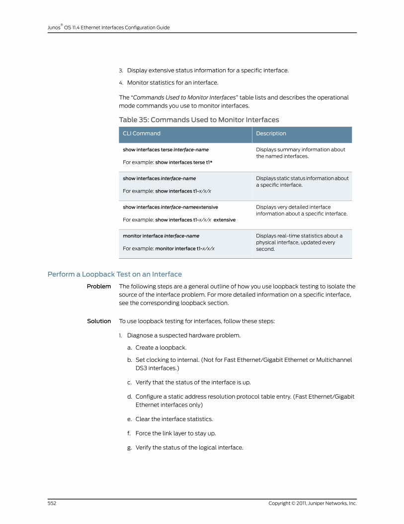
3. Display extensive status information for a specific interface.
4. Monitor statistics for an interface.
The “Commands Used to Monitor Interfaces” table lists and describes the operational
mode commands you use to monitor interfaces.
Table 35: Commands Used toMonitor Interfaces
DescriptionCLI Command
Displays summary information aboutthe named interfaces.
show interfaces terse interface-name
For example: show interfaces terse t1*
Displays static status information abouta specific interface.
show interfaces interface-name
For example: show interfaces t1-x/x/x
Displays very detailed interfaceinformation about a specific interface.
show interfaces interface-nameextensive
For example: show interfaces t1-x/x/x extensive
Displays real-time statistics about aphysical interface, updated everysecond.
monitor interface interface-name
For example: monitor interface t1-x/x/x
Perform a Loopback Test on an Interface
Problem The following steps are a general outline of how you use loopback testing to isolate the
source of the interface problem. For more detailed information on a specific interface,
see the corresponding loopback section.
Solution To use loopback testing for interfaces, follow these steps:
1. Diagnose a suspected hardware problem.
a. Create a loopback.
b. Set clocking to internal. (Not for Fast Ethernet/Gigabit Ethernet or Multichannel
DS3 interfaces.)
c. Verify that the status of the interface is up.
d. Configure a static address resolution protocol table entry. (Fast Ethernet/Gigabit
Ethernet interfaces only)
e. Clear the interface statistics.
f. Force the link layer to stay up.
g. Verify the status of the logical interface.
Copyright © 2011, Juniper Networks, Inc.552
Junos®
OS 11.4 Ethernet Interfaces Configuration Guide

h. Ping the interface.
i. Check for interface error statistics.
2. Diagnose a suspected connection problem.
a. Create a loop from the router to the network.
b. Create a loop to the router from various points in the network.
The “CommandsUsed toPerformLoopbackTestingon Interfaces” table lists and describes
the operational and configuration mode commands you use to perform loopback testing
on interfaces (the commands are shown in the order in which you perform them).
Table 36: Commands Used to Perform Loopback Testing on Interfaces
DescriptionInterface TypeCLI Statement or Command
The loopback statement at the hierarchy levelconfigures a loopback on the interface. Packetscan be looped on either the local router or theremote channel service unit (CSU).
To turn off loopback, remove the loopbackstatement from the configuration.
All interfaces[edit interfaces interface-nameinterface-options]set loopback (local | remote)
Verify the configuration before you commit it.All interfacesshow
Save the set of changes to the database andcause the changes to take operational effect.
Use after you have verified a configuration in allconfiguration steps.
All interfacescommit
The clocking statement at this hierarchy levelconfigures the clock source of the interface tointernal.
T1, T3, ATM, and SONETinterfaces
[edit interfaces interface-name]set clocking internal
Display static status information about aspecific interface.
Used for all interfacesshow interfaces interface-name
Thearp statement at this hierarchy level definesmappings between IP and Media Access Control(MAC) addresses.
Fast Ethernet and GigabitEthernet interfaces
[edit interfaces interface-name unitlogical-unit-number family inetaddress address]arp ip-address macmac-address
Display the entries in the ARP table withoutattempting to determine the hostname thatcorresponds to the IP address (the no-resolveoption).
Fast Ethernet and GigabitEthernet interfaces
show arp no-resolve
Reset the statistics for an interface to zero.All interfacesclear interfaces statistics interface-name
The encapsulation statement at this hierarchylevel sets the encapsulation to the CiscoHigh-level Data-Link Control (HDLC) transportprotocol on the physical interface.
T1, T3, SONET, andMultichannel DS3interfaces
[edit interfaces interface-name ]set encapsulation cisco-hdlc
553Copyright © 2011, Juniper Networks, Inc.
Chapter 34: Investigate Fast Ethernet and Gigabit Ethernet Interfaces
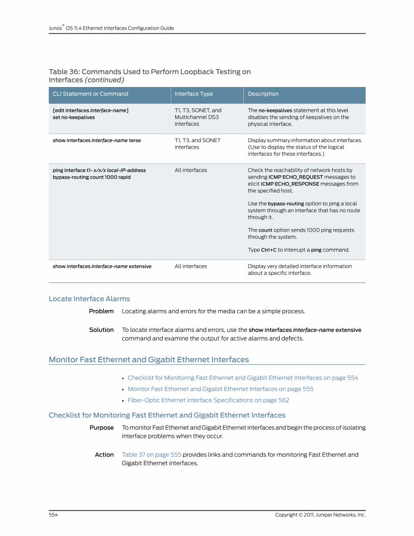
Table 36: Commands Used to Perform Loopback Testing onInterfaces (continued)
DescriptionInterface TypeCLI Statement or Command
The no-keepalives statement at this leveldisables the sending of keepalives on thephysical interface.
T1, T3, SONET, andMultichannel DS3interfaces
[edit interfaces interface-name]set no-keepalives
Display summary information about interfaces.(Use to display the status of the logicalinterfaces for these interfaces.)
T1, T3, and SONETinterfaces
show interfaces interface-name terse
Check the reachability of network hosts bysending ICMP ECHO_REQUEST messages toelicit ICMP ECHO_RESPONSE messages fromthe specified host.
Use the bypass-routing option to ping a localsystem through an interface that has no routethrough it.
The count option sends 1000 ping requeststhrough the system.
Type Ctrl+C to interrupt a ping command.
All interfacesping interface t1- x/x/x local-IP-addressbypass-routing count 1000 rapid
Display very detailed interface informationabout a specific interface.
All interfacesshow interfaces interface-name extensive
Locate Interface Alarms
Problem Locating alarms and errors for the media can be a simple process.
Solution To locate interface alarms and errors, use the show interfaces interface-name extensive
command and examine the output for active alarms and defects.
Monitor Fast Ethernet and Gigabit Ethernet Interfaces
• Checklist for Monitoring Fast Ethernet and Gigabit Ethernet Interfaces on page 554
• Monitor Fast Ethernet and Gigabit Ethernet Interfaces on page 555
• Fiber-Optic Ethernet Interface Specifications on page 562
Checklist for Monitoring Fast Ethernet and Gigabit Ethernet Interfaces
Purpose To monitor Fast Ethernet and Gigabit Ethernet interfaces and begin the process of isolating
interface problems when they occur.
Action Table 37 on page 555 provides links and commands for monitoring Fast Ethernet and
Gigabit Ethernet interfaces.
Copyright © 2011, Juniper Networks, Inc.554
Junos®
OS 11.4 Ethernet Interfaces Configuration Guide

Table 37: Checklist for Monitoring Fast Ethernet and Gigabit EthernetInterfaces
Command or ActionTasks
“Monitor Fast Ethernet and Gigabit Ethernet Interfaces” on page 555
show interfaces terse (fe* | ge*)1. Display the Status of Fast Ethernet Interfaces on page 555
show interfaces (fe-fpc/pic/port | ge-fpc/pic/port)2. Display the Status of a Specific Fast Ethernet or GigabitEthernet Interface on page 557
show interfaces (fe-fpc/pic/port | ge-fpc/pic/port) extensive3. Display Extensive Status Information for a Specific FastEthernet or Gigabit Ethernet Interface on page 558
monitor interface (fe-fpc/pic/port | ge-fpc/pic/port)4. Monitor Statistics for a Fast Ethernet or Gigabit EthernetInterface on page 561
5. Fiber-Optic Ethernet Interface Specifications on page 562
Meaning You can use the above described commands to monitor and to display the configurations
for Fast Ethernet and Gigabit Ethernet interfaces.
Monitor Fast Ethernet and Gigabit Ethernet Interfaces
By monitoring Fast Ethernet and Gigabit Ethernet interfaces, you begin to isolate Fast
Ethernet and Gigabit Ethernet interface problems when they occur.
To monitor your Fast Ethernet and Gigabit Ethernet interfaces, follow these steps:
1. Display the Status of Fast Ethernet Interfaces on page 555
2. Display the Status of Gigabit Ethernet Interfaces on page 556
3. Display the Status of a Specific Fast Ethernet or Gigabit Ethernet Interface on page 557
4. Display Extensive Status Information for a Specific Fast Ethernet or Gigabit Ethernet
Interface on page 558
5. Monitor Statistics for a Fast Ethernet or Gigabit Ethernet Interface on page 561
Display the Status of Fast Ethernet Interfaces
Purpose To display the status of Fast Ethernet interfaces, use the following Junos OS
command-line interface (CLI) operational mode command:
Action user@host> show interfaces terse (fe* | ge*)
Sample Output
user@host> show interfaces terse fe*Interface Admin Link Proto Local Remotefe-2/1/0 up upfe-2/1/0.0 up up inet 10.116.115.217/29fe-3/0/2 up downfe-3/0/2.0 up downfe-3/0/3 up up
555Copyright © 2011, Juniper Networks, Inc.
Chapter 34: Investigate Fast Ethernet and Gigabit Ethernet Interfaces

fe-3/0/3.0 up up inet 192.168.223.65/30fe-4/1/0 down upfe-4/1/0.0 up down inet 10.150.59.133/30fe-4/1/1 up upfe-4/1/1.0 up up inet 10.150.59.129/30fe-4/1/2 up downfe-4/1/2.0 up down
Meaning The sample output lists only the Fast Ethernet interfaces. It shows the status of both the
physical and logical interfaces. For a description of what the output means, see Table
38 on page 556.
Table 38: Status of Fast Ethernet Interfaces
Status DescriptionLogicalInterface
PhysicalInterface
This interface has both the physical and logical links upand running.
fe-2/1/0.0
Admin Up
Link Up
fe-2/1/0
Admin Up
Link Up
This interface has the physical link down, the link layerdown, or both down (Link Down). The logical link is alsodown as a result.
fe-3/0/2.0
Admin Up
Link Down
fe-3/0/2
Admin Up
Link Down
This interface is administratively disabled and the physicallink is healthy (Link Up), but the logical interface is notestablished. The logical interface is down because thephysical link is disabled.
fe-4/1/0.0
Admin Up
Link Down
fe-4/1/0
Admin Down
Link Up
This interface has both the physical and logical links down.fe-4/1/2.0
Admin Up
Link Down
fe-4/1/2
Admin Up
Link Down
Display the Status of Gigabit Ethernet Interfaces
Purpose To display the status of Gigabit Ethernet interfaces, use the following Junos OS
command-line interface (CLI) operational mode command:
Action user@host> show interfaces terse ge*Interface Admin Link Proto Local Remotege-2/2/0 down down
Sample Output
ge-2/2/0.0 up down inet 65.113.23.105/30ge-2/3/0 up upge-2/3/0.0 up up inet 65.115.56.57/30ge-3/1/0 up upge-3/1/0.0 up up inet 65.115.56.193/30ge-3/2/0 up down
Copyright © 2011, Juniper Networks, Inc.556
Junos®
OS 11.4 Ethernet Interfaces Configuration Guide
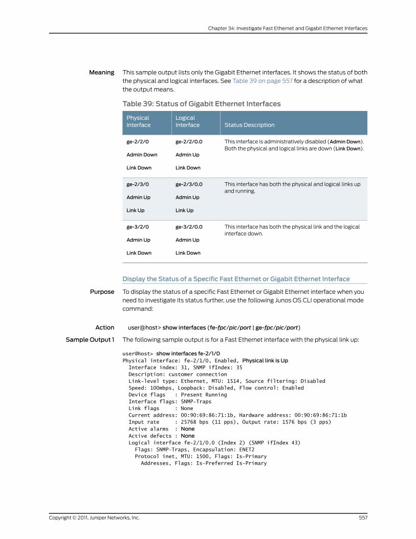
Meaning This sample output lists only the Gigabit Ethernet interfaces. It shows the status of both
the physical and logical interfaces. See Table 39 on page 557 for a description of what
the output means.
Table 39: Status of Gigabit Ethernet Interfaces
Status DescriptionLogicalInterface
PhysicalInterface
This interface is administratively disabled (Admin Down).Both the physical and logical links are down (Link Down).
ge-2/2/0.0
Admin Up
Link Down
ge-2/2/0
Admin Down
Link Down
This interface has both the physical and logical links upand running.
ge-2/3/0.0
Admin Up
Link Up
ge-2/3/0
Admin Up
Link Up
This interface has both the physical link and the logicalinterface down.
ge-3/2/0.0
Admin Up
Link Down
ge-3/2/0
Admin Up
Link Down
Display the Status of a Specific Fast Ethernet or Gigabit Ethernet Interface
Purpose To display the status of a specific Fast Ethernet or Gigabit Ethernet interface when you
need to investigate its status further, use the following Junos OS CLI operational mode
command:
Action user@host> show interfaces (fe-fpc/pic/port | ge-fpc/pic/port)
Sample Output 1 The following sample output is for a Fast Ethernet interface with the physical link up:
user@host> show interfaces fe-2/1/0Physical interface: fe-2/1/0, Enabled, Physical link is Up Interface index: 31, SNMP ifIndex: 35 Description: customer connection Link-level type: Ethernet, MTU: 1514, Source filtering: Disabled Speed: 100mbps, Loopback: Disabled, Flow control: Enabled Device flags : Present Running Interface flags: SNMP-Traps Link flags : None Current address: 00:90:69:86:71:1b, Hardware address: 00:90:69:86:71:1b Input rate : 25768 bps (11 pps), Output rate: 1576 bps (3 pps) Active alarms : None Active defects : None Logical interface fe-2/1/0.0 (Index 2) (SNMP ifIndex 43) Flags: SNMP-Traps, Encapsulation: ENET2 Protocol inet, MTU: 1500, Flags: Is-Primary Addresses, Flags: Is-Preferred Is-Primary
557Copyright © 2011, Juniper Networks, Inc.
Chapter 34: Investigate Fast Ethernet and Gigabit Ethernet Interfaces

Destination: 10.116.151.218/29, Local: 10.119.115.217 Broadcast: 10.116.151.225
Sample Output 2 The following output is for a Gigabit Ethernet interface with the physical link up:
user@host> show interfaces ge-3/1/0Physical interface: ge-3/1/0, Enabled, Physical link is Up Interface index: 41, SNMP ifIndex: 55 Description: customer connection Link-level type: Ethernet, MTU: 1514, Source filtering: Disabled Speed: 1000mbps, Loopback: Disabled, Flow control: Enabled Device flags : Present Running Interface flags: SNMP-Traps Link flags : None Current address: 00:90:69:85:71:99, Hardware address: 00:90:69:85:71:99 Input rate : 7412216 bps (1614 pps), Output rate: 2431184 bps (1776 pps) Active alarms : None Active defects : None Logical interface ge-3/1/0.0 (Index 11) (SNMP ifIndex 57) Flags: SNMP-Traps, Encapsulation: ENET2 Protocol inet, MTU: 1500 Addresses, Flags: Is-Preferred Is-Primary Destination: 10.117.65.192/30, Local: 10.115.65.193 Broadcast: 10.115.65.195
Meaning The first line of sample output 1 and 2 shows that the physical link is up. This means that
the physical link is healthy and can pass packets. Further down the sample output, look
for active alarms and defects. If you see active alarms or defects, to further diagnose the
problem, see Step 3, “Display Extensive Status Information for a Specific Fast Ethernet
or Gigabit Ethernet Interface” on page 558, to display more extensive information about
the Fast Ethernet interface and the physical interface that is down.
Display Extensive Status Information for a Specific Fast Ethernet or GigabitEthernet Interface
Purpose To display extensive status information about a specific Fast Ethernet or Gigabit Ethernet
interface, use the following Junos OS CLI operational mode command:
Action user@host> show interfaces (fe-fpc/pic/port | ge-fpc/pic/port) extensive
Sample Output The following sample output is for a Fast Ethernet interface:
user@router> show interfaces fe-1/3/3 extensivePhysical interface: fe-1/3/3, Enabled, Physical link is Up Interface index: 47, SNMP ifIndex: 38 Description: Test Link-level type: Ethernet, MTU: 1514, Source filtering: Disabled Speed: 100mbps, Loopback: Disabled, Flow control: Enabled Device flags : Present Running Interface flags: SNMP-Traps Link flags : None Current address: 00:90:69:8d:2c:de, Hardware address: 00:90:69:8d:2c:de Statistics last cleared: 2002-01-11 23:03:09 UTC (1w2d 23:54 ago) Traffic statistics: Input bytes : 373012658 0 bps Output bytes : 153026154 1392 bps Input packets: 1362858 0 pps
Copyright © 2011, Juniper Networks, Inc.558
Junos®
OS 11.4 Ethernet Interfaces Configuration Guide

Output packets: 1642918 3 ppsInput errors:Errors: 0 , Drops: 0, Framing errors: 0, Runts: 0, Policed discards: 503660
L3 incompletes: 1 , L2 channel errors: 0 , L2 mismatch timeouts: 0 FIFO errors: 0 Output errors: Carrier transitions: 0, Errors: 0, Collisions: 0, Drops: 0, Aged packets: 0 HS link CRC errors: 0, FIFO errors: 0 Active alarms : None Active defects : None MAC statistics: Receive Transmit Total octets 439703575 177452093 Total packets 1866532 1642916 Unicast packets 972137 1602563 Broadcast packets 30 2980 Multicast packets 894365 37373 CRC/Align errors 0 0 FIFO errors 0 0 MAC control frames 0 0 MAC pause frames 0 0 Oversized frames 0 Jabber frames 0 Fragment frames 0 VLAN tagged frames 0 Code violations 0 Filter statistics: Input packet count 1866532 Input packet rejects 0
Input DA rejects 503674Input SA rejects 0
Output packet count 1642916 Output packet pad count 0 Output packet error count 0 CAM destination filters: 5, CAM source filters: 0
Autonegotiation information:Negotiation status: Complete, Link partner status: OK
Link partner: Full-duplex, Flow control: None PFE configuration: Destination slot: 1, Stream number: 15 CoS transmit queue bandwidth: Queue0: 95, Queue1: 0, Queue2: 0, Queue3: 5 CoS weighted round-robin: Queue0: 95, Queue1: 0, Queue2: 0, Queue3: 5 Logical interface fe-1/3/3.0 (Index 8) (SNMP ifIndex 69) Description: Test Flags: SNMP-Traps, Encapsulation: ENET2 Protocol inet, MTU: 1500, Flags: None Addresses, Flags: Is-Preferred Is-Primary Destination: 10.115.107.192/29, Local: 10.115.107.193 Broadcast: 10.115.107.199
Meaning The sample output shows where the errors might be occurring and includes
autonegotiation information. See Table 40 on page 560 for a description of errors to look
for.
559Copyright © 2011, Juniper Networks, Inc.
Chapter 34: Investigate Fast Ethernet and Gigabit Ethernet Interfaces
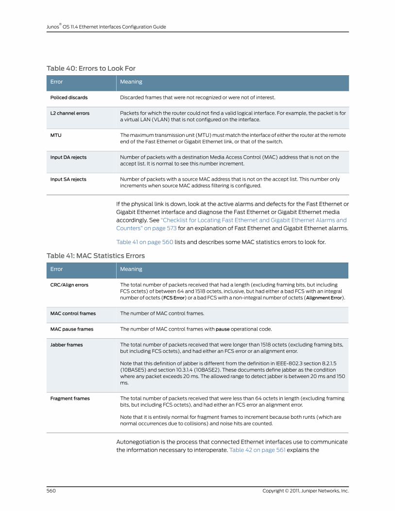
Table 40: Errors to Look For
MeaningError
Discarded frames that were not recognized or were not of interest.Policed discards
Packets for which the router could not find a valid logical interface. For example, the packet is fora virtual LAN (VLAN) that is not configured on the interface.
L2 channel errors
The maximum transmission unit (MTU) must match the interface of either the router at the remoteend of the Fast Ethernet or Gigabit Ethernet link, or that of the switch.
MTU
Number of packets with a destination Media Access Control (MAC) address that is not on theaccept list. It is normal to see this number increment.
Input DA rejects
Number of packets with a source MAC address that is not on the accept list. This number onlyincrements when source MAC address filtering is configured.
Input SA rejects
If the physical link is down, look at the active alarms and defects for the Fast Ethernet or
Gigabit Ethernet interface and diagnose the Fast Ethernet or Gigabit Ethernet media
accordingly. See “Checklist for Locating Fast Ethernet and Gigabit Ethernet Alarms and
Counters” on page 573 for an explanation of Fast Ethernet and Gigabit Ethernet alarms.
Table 41 on page 560 lists and describes some MAC statistics errors to look for.
Table 41: MAC Statistics Errors
MeaningError
The total number of packets received that had a length (excluding framing bits, but includingFCS octets) of between 64 and 1518 octets, inclusive, but had either a bad FCS with an integralnumber of octets (FCSError) or a bad FCS with a non-integral number of octets (AlignmentError).
CRC/Align errors
The number of MAC control frames.MAC control frames
The number of MAC control frames with pause operational code.MAC pause frames
The total number of packets received that were longer than 1518 octets (excluding framing bits,but including FCS octets), and had either an FCS error or an alignment error.
Note that this definition of jabber is different from the definition in IEEE-802.3 section 8.2.1.5(10BASE5) and section 10.3.1.4 (10BASE2). These documents define jabber as the conditionwhere any packet exceeds 20 ms. The allowed range to detect jabber is between 20 ms and 150ms.
Jabber frames
The total number of packets received that were less than 64 octets in length (excluding framingbits, but including FCS octets), and had either an FCS error an alignment error.
Note that it is entirely normal for fragment frames to increment because both runts (which arenormal occurrences due to collisions) and noise hits are counted.
Fragment frames
Autonegotiation is the process that connected Ethernet interfaces use to communicate
the information necessary to interoperate. Table 42 on page 561 explains the
Copyright © 2011, Juniper Networks, Inc.560
Junos®
OS 11.4 Ethernet Interfaces Configuration Guide
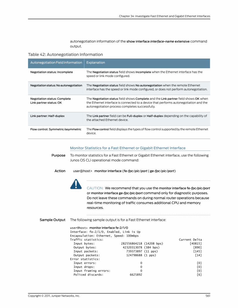
autonegotiation information of the show interface interface-name extensive command
output.
Table 42: Autonegotiation Information
ExplanationAutonegotiationField Information
The Negotiation status field shows Incomplete when the Ethernet interface has thespeed or link mode configured.
Negotiation status: Incomplete
The Negotiation status field shows No autonegotiation when the remote Ethernetinterface has the speed or link mode configured, or does not perform autonegotiation.
Negotiationstatus:Noautonegotiation
The Negotiation status field shows Complete and the Link partner field shows OK whenthe Ethernet interface is connected to a device that performs autonegotiation and theautonegotiation process completes successfully.
Negotiation status: CompleteLink partner status: OK
The Link partner field can be Full-duplex or Half-duplex depending on the capability ofthe attached Ethernet device.
Link partner: Half-duplex
TheFlowcontrol field displays the types of flow control supported by the remote Ethernetdevice.
Flow control: Symmetric/asymmetric
Monitor Statistics for a Fast Ethernet or Gigabit Ethernet Interface
Purpose To monitor statistics for a Fast Ethernet or Gigabit Ethernet interface, use the following
Junos OS CLI operational mode command:
Action user@host> monitor interface (fe-fpc/pic/port | ge-fpc/pic/port)
CAUTION: We recommend that you use themonitor interface fe-fpc/pic/port
ormonitor interface ge-fpc/pic/port command only for diagnostic purposes.
Do not leave these commands on during normal router operations becausereal-timemonitoring of traffic consumes additional CPU andmemoryresources.
Sample Output The following sample output is for a Fast Ethernet interface:
user@host> monitor interface fe-2/1/0Interface: fe-2/1/0, Enabled, Link is UpEncapsulation: Ethernet, Speed: 100mbpsTraffic statistics: Current Delta Input bytes: 282556864218 (14208 bps) [40815] Output bytes: 42320313078 (384 bps) [890] Input packets: 739373897 (11 pps) [145] Output packets: 124798688 (1 pps) [14]Error statistics: Input errors: 0 [0] Input drops: 0 [0] Input framing errors: 0 [0] Policed discards: 6625892 [6]
561Copyright © 2011, Juniper Networks, Inc.
Chapter 34: Investigate Fast Ethernet and Gigabit Ethernet Interfaces
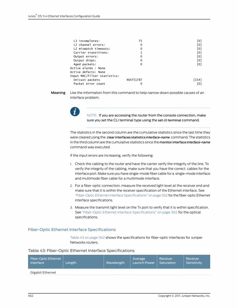
L3 incompletes: 75 [0] L2 channel errors: 0 [0] L2 mismatch timeouts: 0 [0] Carrier transitions: 1 [0] Output errors: 0 [0] Output drops: 0 [0] Aged packets: 0 [0]Active alarms : NoneActive defects: NoneInput MAC/Filter statistics: Unicast packets 464751787 [154] Packet error count 0 [0]
Meaning Use the information from this command to help narrow down possible causes of an
interface problem.
NOTE: If you are accessing the router from the console connection, makesure you set the CLI terminal type using the set cli terminal command.
The statistics in the second column are the cumulative statistics since the last time they
were cleared using the clear interfacesstatistics interface-name command. The statistics
in the third column are the cumulative statistics since themonitor interface interface-name
command was executed.
If the input errors are increasing, verify the following:
1. Check the cabling to the router and have the carrier verify the integrity of the line. To
verify the integrity of the cabling, make sure that you have the correct cables for the
interface port. Make sure you have single-mode fiber cable for a single-mode interface
and multimode fiber cable for a multimode interface.
2. For a fiber-optic connection, measure the received light level at the receiver end and
make sure that it is within the receiver specification of the Ethernet interface. See
“Fiber-Optic Ethernet Interface Specifications” on page 562 for the fiber-optic Ethernet
interface specifications.
3. Measure the transmit light level on the Tx port to verify that it is within specification.
See “Fiber-Optic Ethernet Interface Specifications” on page 562 for the optical
specifications.
Fiber-Optic Ethernet Interface Specifications
Table 43 on page 562 shows the specifications for fiber-optic interfaces for Juniper
Networks routers.
Table 43: Fiber-Optic Ethernet Interface Specifications
ReceiverSensitivity
ReceiverSaturation
AverageLaunch PowerWavelengthLength
Fiber-OpticEthernetInterface
Gigabit Ethernet
Copyright © 2011, Juniper Networks, Inc.562
Junos®
OS 11.4 Ethernet Interfaces Configuration Guide

Table 43: Fiber-Optic Ethernet Interface Specifications (continued)
ReceiverSensitivity
ReceiverSaturation
AverageLaunch PowerWavelengthLength
Fiber-OpticEthernetInterface
Duplex SC connector
-23 dBm (BER1012) for SMF
-3 dBm-3 to +2 dBm1480 to 1580nm
49.5-mile 70-km reach on8.2-micrometer SMF
LH optical interface
-19 dBm-3 dBm-11 to -3 dBm1270 to 1355 nm6.2-mile 10-km reach on9/125-micrometer SMF
1804.5-ft 550-m reach on62.5/125- and50/125-micrometer MMF
LX optical interface
-17 dBm-3 dBm-9.5 to -4 dBm830 to 860 nm656-ft 200-m reach on62.5/125-micrometerMMF
1640-ft 500-m reach on50/125-micrometer MMF
SX optical interface
Fast Ethernet 8-Port
-34 dBm-14 dBm-20 to -14 dBm1270 to 1380 nm1.24-mile 2-km reach on62.5/125-micrometerMMF
FX optical interfacewith MT-RJ connector
Use Loopback Testing for Fast Ethernet and Gigabit Ethernet Interfaces
• Checklist for Using Loopback Testing for Fast Ethernet and Gigabit Ethernet
Interfaces on page 563
• Diagnose a Suspected Hardware Problem with a Fast Ethernet or Gigabit Ethernet
Interface on page 564
• Create a Loopback on page 565
• Verify That the Fast Ethernet or Gigabit Ethernet Interface Is Up on page 567
• Configure a Static Address Resolution Protocol Table Entry on page 568
• Clear Fast Ethernet or Gigabit Ethernet Interface Statistics on page 570
• Ping the Fast Ethernet or Gigabit Ethernet Interface on page 570
• Check for Fast Ethernet or Gigabit Ethernet Interface Error Statistics on page 571
• Diagnose a Suspected Circuit Problem on page 573
Checklist for Using Loopback Testing for Fast Ethernet and Gigabit Ethernet Interfaces
Purpose To use loopback testing to isolate Fast Ethernet and Gigabit Ethernet interface problems.
Action Table 44 on page 564 provides links and commands for using loopback testing for Fast
Ethernet and Gigabit Ethernet interfaces.
563Copyright © 2011, Juniper Networks, Inc.
Chapter 34: Investigate Fast Ethernet and Gigabit Ethernet Interfaces

Table 44: Checklist for Using Loopback Testing for Fast Ethernet andGigabit Ethernet Interfaces
Command or ActionTasks
“Diagnose a Suspected Hardware Problemwith a Fast Ethernet or Gigabit Ethernet Interface” on page 564
1. Create a Loopback on page 565
Connect the transmit port to the receive port.a. Create a Physical Loopback for a Fiber-Optic Interface on page 565
Cross pin 1 (TX+) and pin 3 (RX+) together, and pin2 (TX-) and pin 6 (RX-) together.
b. Create a Loopback Plug for an RJ-45 Ethernet Interface on page 565
[edit interfaces interface-name (fastether-options |gigether-options)]set loopbackshowcommit
c. Configure a Local Loopback on page 566
show interfaces (fe-fpc/pic/port | ge-fpc/pic/port)2. Verify That the Fast Ethernet or Gigabit Ethernet Interface Is Up onpage 567
show interfaces ge-fpc/pic/port[edit interfaces interface-name unitlogical-unit-number family inet address address]set arp ip-addressmacmac-address showcommitrun show arp no-resolve
3. Configure a Static Address Resolution Protocol Table Entry on page 568
clear interfaces statistics fe-fpc/pic/port |ge-fpc/pic/port
4. Clear Fast Ethernet or Gigabit Ethernet Interface Statistics on page 570
ping remote-IP-address bypass-routing interface(fe-fpc/pic/port | ge-fpc/pic/port count 100 rapid
5. Ping the Fast Ethernet or Gigabit Ethernet Interface on page 570
show interfaces (fe-fpc/pic/port | ge-fpc/pic/port )extensive
6. Check for Fast Ethernet or Gigabit Ethernet Interface Error Statisticson page 571
Perform Steps 2 through 8 from “Diagnose aSuspected Hardware Problem with a Fast Ethernetor Gigabit Ethernet Interface” on page 564.
“Diagnose a Suspected Circuit Problem” on page 573
Diagnose a Suspected Hardware Problemwith a Fast Ethernet or Gigabit Ethernet Interface
Problem When you suspect a hardware problem, take the following steps to help verify if there is
a problem.
Solution To diagnose a suspected hardware problem with the Ethernet interface, follow these
steps:
• Create a Loopback on page 565
• Verify That the Fast Ethernet or Gigabit Ethernet Interface Is Up on page 567
Copyright © 2011, Juniper Networks, Inc.564
Junos®
OS 11.4 Ethernet Interfaces Configuration Guide
• Configure a Static Address Resolution Protocol Table Entry on page 568
• Clear Fast Ethernet or Gigabit Ethernet Interface Statistics on page 570
• Ping the Fast Ethernet or Gigabit Ethernet Interface on page 570
• Check for Fast Ethernet or Gigabit Ethernet Interface Error Statistics on page 571
Create a Loopback
You can create a physical loopback or configure a local loopback to help diagnose a
suspected hardware problem. Creating a physical loopback is recommended because
it allows you to test and verify the transmit and receive ports. If a field engineer is not
available to create the physical loopback, you can configure a local loopback for the
interface. The local loopback creates a loopback internally in the Physical Interface Card
(PIC).
1. Create a Physical Loopback for a Fiber-Optic Interface on page 565
2. Create a Loopback Plug for an RJ-45 Ethernet Interface on page 565
3. Configure a Local Loopback on page 566
Create a Physical Loopback for a Fiber-Optic Interface
Action To create a physical loopback at the port, connect the transmit port to the receive port
using a known good fiber cable.
NOTE: Make sure you use single-mode fiber for a single-mode port andmultimode fiber for amultimode port.
Meaning When you create and then test a physical loopback, you are testing the transmit and
receive ports of the PIC. This action is recommended if a field engineer is available to
create the physical loop as it provides a more complete test of the PIC.
Create a Loopback Plug for an RJ-45 Ethernet Interface
Action To create a loopback plug, cross pin 1 (TX+) and pin 3 (RX+) together, and cross pin 2
(TX-) and pin 6 (RX-) together. You need the following equipment to create the loopback:
• A 6-inch long CAT5 cable
• An RJ-45 connector
• A crimping tool
Figure 35 on page 566 illustrates how to create a loopback plug for an RJ-45 Ethernet
interface.
565Copyright © 2011, Juniper Networks, Inc.
Chapter 34: Investigate Fast Ethernet and Gigabit Ethernet Interfaces
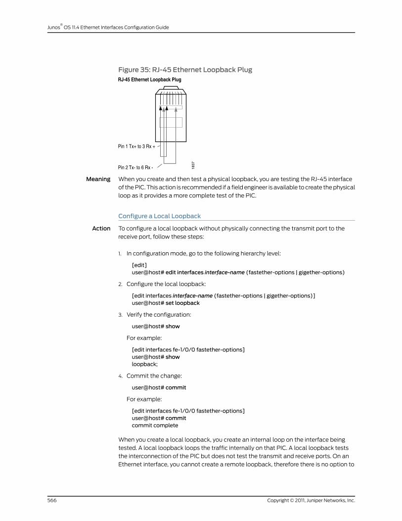
Figure 35: RJ-45 Ethernet Loopback Plug
Meaning When you create and then test a physical loopback, you are testing the RJ-45 interface
of the PIC. This action is recommended if a field engineer is available to create the physical
loop as it provides a more complete test of the PIC.
Configure a Local Loopback
Action To configure a local loopback without physically connecting the transmit port to the
receive port, follow these steps:
1. In configuration mode, go to the following hierarchy level:
[edit]user@host# edit interfaces interface-name (fastether-options | gigether-options)
2. Configure the local loopback:
[edit interfaces interface-name (fastether-options | gigether-options)]user@host# set loopback
3. Verify the configuration:
user@host# show
For example:
[edit interfaces fe-1/0/0 fastether-options]user@host# showloopback;
4. Commit the change:
user@host# commit
For example:
[edit interfaces fe-1/0/0 fastether-options]user@host# commitcommit complete
When you create a local loopback, you create an internal loop on the interface being
tested. A local loopback loops the traffic internally on that PIC. A local loopback tests
the interconnection of the PIC but does not test the transmit and receive ports. On an
Ethernet interface, you cannot create a remote loopback, therefore there is no option to
Copyright © 2011, Juniper Networks, Inc.566
Junos®
OS 11.4 Ethernet Interfaces Configuration Guide
use a local or remote statement. Simply including the loopback statement at the [edit
interfaces interface-name (fastether-options | gigether-options] hierarchy level, places
the interface into local loopback mode.
NOTE: Remember to delete the loopback statement after completing thetest.
Verify That the Fast Ethernet or Gigabit Ethernet Interface Is Up
Purpose Display the status of the Fast Ethernet or Gigabit Ethernet interface to provide the
information you need to determine whether the physical link is up or down.
Action To verify that the status of the Fast Ethernet or Gigabit Ethernet interface is up, use the
following Junos OS command-line interface (CLI) operational mode command:
user@host> show interfaces (fe-fpc/port | ge-fpc/pic/port)
Sample Output user@host# show interfaces fe-1/3/0Physical interface: fe-1/3/0, Enabled, Physical link is Up Interface index: 44, SNMP ifIndex: 35 Link-level type: Ethernet, MTU: 1514, Source filtering: Disabled Speed: 100mbps, Loopback: Disabled , Flow control: Enabled Device flags : Present Running Interface flags: SNMP-Traps Link flags : None Current address: 00:90:69:8d:2c:db, Hardware address: 00:90:69:8d:2c:db Input rate : 0 bps (0 pps), Output rate: 0 bps (0 pps)Active alarms : None
Active defects : None MAC statistics: Input octets: 0, Input packets: 0, Output octets: 0, Output packets: 0 Filter statistics: Filtered packets: 0, Padded packets: 0, Output packet errors: 0 Autonegotiation information: Negotiation status: Incomplete, Link partner status: OK Link partner: Full-duplex, Flow control: None
Meaning The sample output shows that the link is up and there are no alarms in this loopback
configuration. When an internal loopback is configured, the physical loopback should
come up without an alarm.
Sample Output When you see that the physical link is down, there may be a problem with the port. The
following output is an example of the show interfaces fe-fpc/pic/port command when
the physical link is down:
user@router> show interfaces fe-1/3/0Physical interface: fe-1/3/0, Enabled, Physical link is Down Interface index: 44, SNMP ifIndex: 35 Link-level type: Ethernet, MTU: 1514, Source filtering: Disabled Speed: 100mbps, Loopback: Disabled, Flow control: Enabled Device flags : Present Running Down Interface flags: Hardware-Down SNMP-Traps Link flags : None Current address: 00:90:69:8d:2c:db, Hardware address: 00:90:69:8d:2c:db
567Copyright © 2011, Juniper Networks, Inc.
Chapter 34: Investigate Fast Ethernet and Gigabit Ethernet Interfaces

Input rate : 0 bps (0 pps), Output rate: 0 bps (0 pps)Active alarms : LINKActive defects : LINK
MAC statistics: Input octets: 0, Input packets: 0, Output octets: 0, Output packets: 0 Filter statistics: Filtered packets: 0, Padded packets: 0, Output packet errors: 0 Autonegotiation information: Negotiation status: Incomplete, Link partner status: Down Reason: Link partner autonegotiation failure Link partner: Half-duplex, Flow control: None
Meaning The sample output shows that the physical link is down and there are active alarms and
defects.
Table 45 on page 568 presents problem situations and actions for a physical link that is
down.
Table 45: Problems and Solutions for a Physical Link That Is Down
ActionProblem
Verify that the fiber connection is correct.Cable mismatch
Verify that the fiber can successfully loop a known good port of the same type.Damaged and/or dirty cable
Verify that the attenuation is correct per the PIC optical specifications.Too much or too little opticalattenuation
Verify that the Tx power of the optics is within range of the PIC optical specification.The transmit port is not transmittingwithin the dBm optical range per thespecifications
Verify that a single-mode fiber cable is connected to a single-mode interface and thata multimode fiber cable is connected to a multimode interface. (This problem doesnot always cause the physical link to go down; errors and dropped packets aresometimes the result.)
Mismatch between the cable typeand the port
Configure a Static Address Resolution Protocol Table Entry
Purpose Configure a static Address Resolution Protocol (ARP) entry to allow a packet to be sent
out of a looped Ethernet interface.
NOTE: Remove the staticARPentry at theendof the loop test after youhavecompleted theping test, checked interfacestatistics, andmonitored interfacetraffic.
Action To configure a static ARP table entry for a Gigabit Ethernet interface, follow these steps.
You can follow the same procedure to configure a static ARP entry for a Fast Ethernet
interface.
Copyright © 2011, Juniper Networks, Inc.568
Junos®
OS 11.4 Ethernet Interfaces Configuration Guide

1. Find the Media Access Control (MAC) address for the Gigabit Ethernet interface:
user@host> show interfaces ge-fpc/pic/port
2. In configuration mode, go to the following hierarchy level:
[edit]user@host#edit interfaces interface-nameunit logical-unit-number family inet addressaddress
3. Configure the static ARP entry:
user@host# set arp ip-addressmacmac-address
NOTE: TheMACaddressusedshouldbethesameasthephysicaladdressof the port being testedbecause this allows theport to receive the frameswhen you run the ping test.
4. Verify the configuration:
user@host# show
5. Commit the configuration:
user@host# commit
6. Verify that the static ARP entry is installed:
user@host# run show arp no-resolve
Sample Output user@host> show interfaces ge-7/2/1Physical interface: ge-7/2/1, Enabled, Physical link is Down Interface index: 44, SNMP ifIndex: 35 Link-level type: Ethernet, MTU: 1514, Source filtering: Disabled Speed: 100mbps, Loopback: Disabled, Flow control: Enabled Device flags : Present Running Down Interface flags: Hardware-Down SNMP-Traps Link flags : NoneCurrent address: 00:90:69:8d:2c:db, Hardware address: 00:90:69:8d:2c:db
Input rate : 0 bps (0 pps), Output rate: 0 bps (0 pps)[edit interfaces ge-7/2/1 unit 0 family inet address 10.108.120.1/30]
user@host# set arp 10.108.120.2mac 00:90:69:8d:2c:db[edit interfaces ge-7/2/1 unit 0 family inet address 10.108.120.1/30]
user@host# showarp 10.108.120.2 mac 00:90:69:8d:2c:db;[edit interfaces ge-7/2/1 unit 0 family inet address 10.108.120.1/30]
user@host# commitcommit complete[edit interfaces ge-7/2/1 unit 0 family inet address 10.108.120.1/30]
user@host# run show arp no-resolveMAC Address Address Interface Flags00:90:69:8d:2c:db 10.108.120.2 ge-7/2/1.0 permanent00:e0:34:bb:8c:40 209.211.135.1 fxp0.0 none00:a0:a5:28:0c:70 209.211.135.8 fxp0.0 none00:a0:a5:12:12:c7 209.211.135.10 fxp0.0 none
569Copyright © 2011, Juniper Networks, Inc.
Chapter 34: Investigate Fast Ethernet and Gigabit Ethernet Interfaces
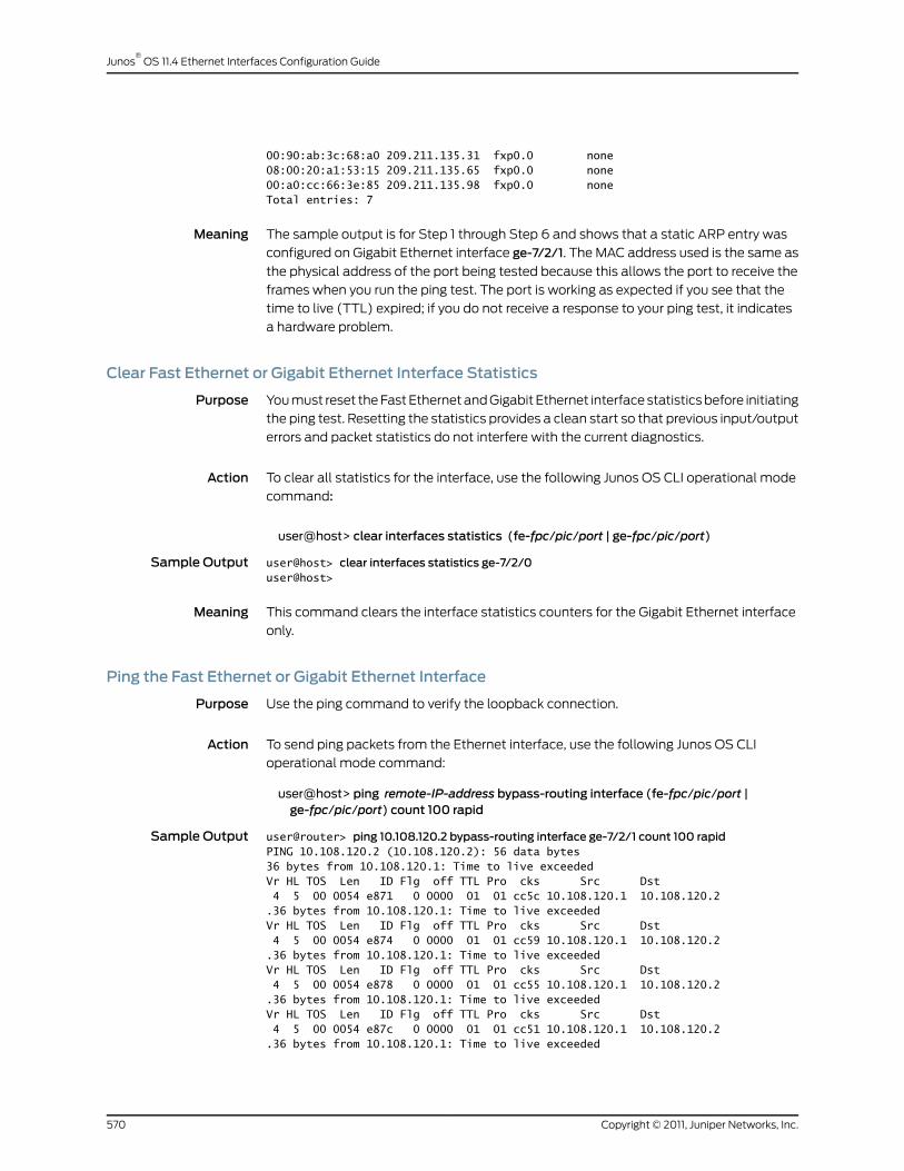
00:90:ab:3c:68:a0 209.211.135.31 fxp0.0 none08:00:20:a1:53:15 209.211.135.65 fxp0.0 none00:a0:cc:66:3e:85 209.211.135.98 fxp0.0 noneTotal entries: 7
Meaning The sample output is for Step 1 through Step 6 and shows that a static ARP entry was
configured on Gigabit Ethernet interface ge-7/2/1. The MAC address used is the same as
the physical address of the port being tested because this allows the port to receive the
frames when you run the ping test. The port is working as expected if you see that the
time to live (TTL) expired; if you do not receive a response to your ping test, it indicates
a hardware problem.
Clear Fast Ethernet or Gigabit Ethernet Interface Statistics
Purpose You must reset the Fast Ethernet and Gigabit Ethernet interface statistics before initiating
the ping test. Resetting the statistics provides a clean start so that previous input/output
errors and packet statistics do not interfere with the current diagnostics.
Action To clear all statistics for the interface, use the following Junos OS CLI operational mode
command:
user@host> clear interfaces statistics (fe-fpc/pic/port | ge-fpc/pic/port)
Sample Output user@host> clear interfaces statistics ge-7/2/0user@host>
Meaning This command clears the interface statistics counters for the Gigabit Ethernet interface
only.
Ping the Fast Ethernet or Gigabit Ethernet Interface
Purpose Use the ping command to verify the loopback connection.
Action To send ping packets from the Ethernet interface, use the following Junos OS CLI
operational mode command:
user@host> ping remote-IP-address bypass-routing interface (fe-fpc/pic/port |ge-fpc/pic/port) count 100 rapid
Sample Output user@router> ping 10.108.120.2 bypass-routing interface ge-7/2/1 count 100 rapidPING 10.108.120.2 (10.108.120.2): 56 data bytes36 bytes from 10.108.120.1: Time to live exceededVr HL TOS Len ID Flg off TTL Pro cks Src Dst 4 5 00 0054 e871 0 0000 01 01 cc5c 10.108.120.1 10.108.120.2 .36 bytes from 10.108.120.1: Time to live exceededVr HL TOS Len ID Flg off TTL Pro cks Src Dst 4 5 00 0054 e874 0 0000 01 01 cc59 10.108.120.1 10.108.120.2 .36 bytes from 10.108.120.1: Time to live exceededVr HL TOS Len ID Flg off TTL Pro cks Src Dst 4 5 00 0054 e878 0 0000 01 01 cc55 10.108.120.1 10.108.120.2 .36 bytes from 10.108.120.1: Time to live exceededVr HL TOS Len ID Flg off TTL Pro cks Src Dst 4 5 00 0054 e87c 0 0000 01 01 cc51 10.108.120.1 10.108.120.2 .36 bytes from 10.108.120.1: Time to live exceeded
Copyright © 2011, Juniper Networks, Inc.570
Junos®
OS 11.4 Ethernet Interfaces Configuration Guide
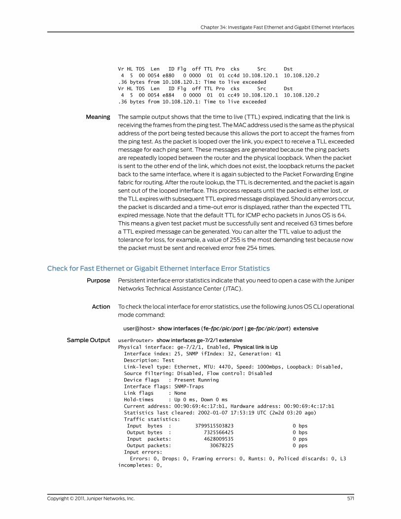
Vr HL TOS Len ID Flg off TTL Pro cks Src Dst 4 5 00 0054 e880 0 0000 01 01 cc4d 10.108.120.1 10.108.120.2 .36 bytes from 10.108.120.1: Time to live exceededVr HL TOS Len ID Flg off TTL Pro cks Src Dst 4 5 00 0054 e884 0 0000 01 01 cc49 10.108.120.1 10.108.120.2 .36 bytes from 10.108.120.1: Time to live exceeded
Meaning The sample output shows that the time to live (TTL) expired, indicating that the link is
receiving the frames from the ping test. The MAC address used is the same as the physical
address of the port being tested because this allows the port to accept the frames from
the ping test. As the packet is looped over the link, you expect to receive a TLL exceeded
message for each ping sent. These messages are generated because the ping packets
are repeatedly looped between the router and the physical loopback. When the packet
is sent to the other end of the link, which does not exist, the loopback returns the packet
back to the same interface, where it is again subjected to the Packet Forwarding Engine
fabric for routing. After the route lookup, the TTL is decremented, and the packet is again
sent out of the looped interface. This process repeats until the packed is either lost, or
the TLL expires with subsequent TTL expired message displayed. Should any errors occur,
the packet is discarded and a time-out error is displayed, rather than the expected TTL
expired message. Note that the default TTL for ICMP echo packets in Junos OS is 64.
This means a given test packet must be successfully sent and received 63 times before
a TTL expired message can be generated. You can alter the TTL value to adjust the
tolerance for loss, for example, a value of 255 is the most demanding test because now
the packet must be sent and received error free 254 times.
Check for Fast Ethernet or Gigabit Ethernet Interface Error Statistics
Purpose Persistent interface error statistics indicate that you need to open a case with the Juniper
Networks Technical Assistance Center (JTAC).
Action To check the local interface for error statistics, use the following Junos OS CLI operational
mode command:
user@host> show interfaces (fe-fpc/pic/port | ge-fpc/pic/port) extensive
Sample Output user@router> show interfaces ge-7/2/1 extensivePhysical interface: ge-7/2/1, Enabled, Physical link is Up Interface index: 25, SNMP ifIndex: 32, Generation: 41 Description: Test Link-level type: Ethernet, MTU: 4470, Speed: 1000mbps, Loopback: Disabled, Source filtering: Disabled, Flow control: Disabled Device flags : Present Running Interface flags: SNMP-Traps Link flags : None Hold-times : Up 0 ms, Down 0 ms Current address: 00:90:69:4c:17:b1, Hardware address: 00:90:69:4c:17:b1 Statistics last cleared: 2002-01-07 17:53:19 UTC (2w2d 03:20 ago) Traffic statistics: Input bytes : 3799515503823 0 bps Output bytes : 7325566425 0 bps Input packets: 4628009535 0 pps Output packets: 30678225 0 pps Input errors: Errors: 0, Drops: 0, Framing errors: 0, Runts: 0, Policed discards: 0, L3 incompletes: 0,
571Copyright © 2011, Juniper Networks, Inc.
Chapter 34: Investigate Fast Ethernet and Gigabit Ethernet Interfaces

L2 channel errors: 0, L2 mismatch timeouts: 0, FIFO errors: 0 Output errors: Carrier transitions: 14, Errors: 0, Drops: 0, Collisions: 0, Aged packets: 0, FIFO errors: 0, HS link CRC errors: 0Active alarms : None
Active defects : None MAC statistics: Receive Transmit Total octets 3883579444813 7880356346 Total packets 4628009534 30678237 Unicast packets 4627879788 29893563 Broadcast packets 30 464 Multicast packets 129716 784210 CRC/Align errors 0 0 FIFO errors 0 0 MAC control frames 0 0 MAC pause frames 0 0 Oversized frames 0 Jabber frames 0 Fragment frames 0 VLAN tagged frames 0 Code violations 0 Filter statistics: Input packet count 4628009244 Input packet rejects 0 Input DA rejects 0 Input SA rejects 0 Output packet count 30678237 Output packet pad count 856248 Output packet error count 0 CAM destination filters: 9, CAM source filters: 0 Autonegotiation information: Negotiation status: Complete, Link partner status: Ok, Link partner: Full-duplex, Flow control: None PFE configuration: Destination slot: 7 CoS transmit queue Bandwidth Buffer Priority Limit % bps % bytes 0 best-effort 0 0 0 0 low none 1 expedited-forwarding 0 0 0 0 low none 2 assured-forwarding 0 0 0 0 low none 3 network-control 0 0 0 0 low none Logical interface ge-7/2/1.0 (Index 23) (SNMP ifIndex 48) (Generation 38) Description: To Cosine Left 23/1 Flags: SNMP-Traps Encapsulation: ENET2 Protocol inet, MTU: 4456, Flags: None, Generation: 85 Route table: 0 Addresses, Flags: Is-Preferred Is-Primary Destination: 10.108.120.0/30, Local: 10.108.120.1, Broadcast: 10.108.120.3,
Generation: 81 Protocol iso, MTU: 4453, Flags: None, Generation: 86 Route table: 0
Meaning Check for any error statistics. There should not be any input or output errors. If there are
any persistent input or output errors, open a case with the Juniper Networks Technical
Assistance Center (JTAC) at [email protected], or at 1-888-314-JTAC (within the United
States) or 1-408-745-9500 (from outside the United States).
Copyright © 2011, Juniper Networks, Inc.572
Junos®
OS 11.4 Ethernet Interfaces Configuration Guide

Diagnose a Suspected Circuit Problem
Purpose When you suspect a circuit problem, it is important to work with the transport-layer
engineer to resolve the problem. The transport-layer engineer may create a loop to the
router from various points in the network. You can then perform tests to verify the
connection from the router to that loopback in the network.
Action After the transport-layer engineer has created the loop to the router from the network,
you must verify the connection from the router to the loopback in the network. Follow
Step 2 through Step 8 in “Diagnose a Suspected Hardware Problem with a Fast Ethernet
or Gigabit Ethernet Interface” on page 564. Keep in mind that any problems encountered
in the test indicate a problem with the connection from the router to the loopback in the
network.
By performing tests to loopbacks at various points in the network, you can isolate the
source of the problem.
Locate the Fast Ethernet and Gigabit Ethernet LINK Alarm and Counters
• Checklist for Locating Fast Ethernet and Gigabit Ethernet Alarms and
Counters on page 573
• Display the Fast Ethernet or Gigabit Ethernet Interface LINK Alarm on page 573
• Fast Ethernet and Gigabit Ethernet Counters on page 575
Checklist for Locating Fast Ethernet and Gigabit Ethernet Alarms and Counters
Purpose To locate LINK alarm and major counters associated with Fast Ethernet and Gigabit
Ethernet interfaces.
Action Table 46 on page 573 provides links and commands for locating LINK alarm and major
counters for Fast Ethernet and Gigabit Ethernet interfaces.
Table46:Checklist forLocatingFastEthernetandGigabitEthernetAlarmsand Counters
Command or ActionTasks
show interfaces (fe-fpc/pic/port | ge-fpc/pic/port) extensive“Display the Fast Ethernet or Gigabit EthernetInterface LINK Alarm” on page 573
“Fast Ethernet and Gigabit Ethernet Counters” onpage 575
Display the Fast Ethernet or Gigabit Ethernet Interface LINK Alarm
Problem To display the Fast Ethernet or Gigabit Ethernet LINK alarm, use the following Junos OS
command-line interface (CLI) operational mode command:
Solution user@host> show interfaces (fe-fpc/pic/port | ge-fpc/pic/port) extensive
573Copyright © 2011, Juniper Networks, Inc.
Chapter 34: Investigate Fast Ethernet and Gigabit Ethernet Interfaces

Sample Output The following sample output is for a Fast Ethernet interface:
user@host> show interfaces fe-1/3/3 extensivePhysical interface: fe-1/3/3, Enabled, Physical link is Down Interface index: 47, SNMP ifIndex: 38 Description: Test Link-level type: Ethernet, MTU: 1514, Source filtering: Disabled Speed: 100mbps, Loopback: Disabled, Flow control: Enabled Device flags : Present Running Interface flags: SNMP-Traps Link flags : None Current address: 00:90:69:8d:2c:de, Hardware address: 00:90:69:8d:2c:de Statistics last cleared: 2002-01-11 23:03:09 UTC (1w2d 23:54 ago) Traffic statistics: Input bytes : 373012658 0 bps Output bytes : 153026154 1392 bps Input packets: 1362858 0 pps Output packets: 1642918 3 pps Input errors: Errors: 0, Drops: 0, Framing errors: 0, Runts: 0, Policed discards: 503660 L3 incompletes: 1 , L2 channel errors: 0, L2 mismatch timeouts: 0 FIFO errors: 0 Output errors: Carrier transitions: 0, Errors: 0, Collisions: 0, Drops: 0, Aged packets: 0 HS link CRC errors: 0, FIFO errors: 0Active alarms : LINK
Active defects : LINK MAC statistics: Receive Transmit Total octets 439703575 177452093 Total packets 1866532 1642916 Unicast packets 972137 1602563 Broadcast packets 30 2980 Multicast packets 894365 37373 CRC/Align errors 0 0 FIFO errors 0 0 MAC control frames 0 0 MAC pause frames 0 0 Oversized frames 0 Jabber frames 0 Fragment frames 0 VLAN tagged frames 0 Code violations 0 Filter statistics: Input packet count 1866532 Input packet rejects 0 Input DA rejects 503674 Input SA rejects 0 Output packet count 1642916 Output packet pad count 0 Output packet error count 0 CAM destination filters: 5, CAM source filters: 0 Autonegotiation information: Negotiation status: Complete, Link partner status: OK Link partner: Full-duplex, Flow control: None PFE configuration: Destination slot: 1, Stream number: 15 CoS transmit queue bandwidth: Queue0: 95, Queue1: 0, Queue2: 0, Queue3: 5 CoS weighted round-robin: Queue0: 95, Queue1: 0, Queue2: 0, Queue3: 5 Logical interface fe-1/3/3.0 (Index 8) (SNMP ifIndex 69)
Copyright © 2011, Juniper Networks, Inc.574
Junos®
OS 11.4 Ethernet Interfaces Configuration Guide
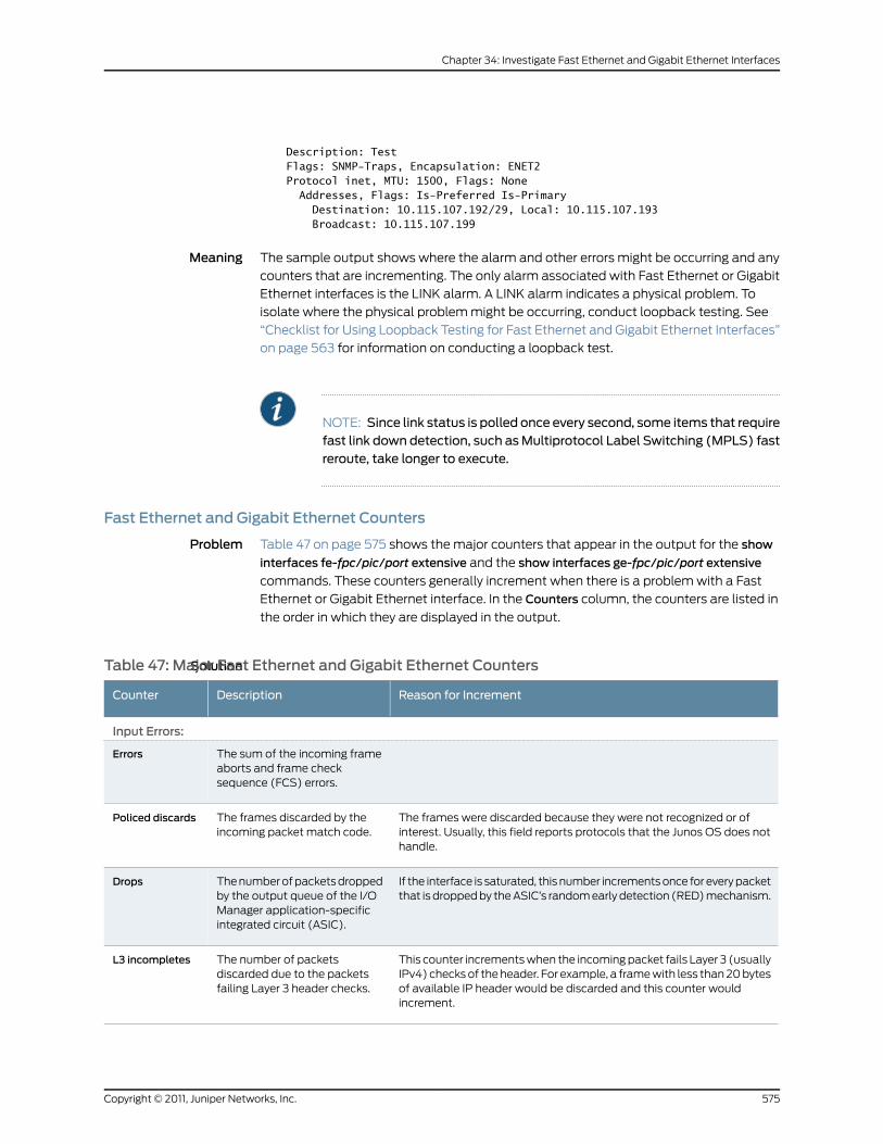
Description: Test Flags: SNMP-Traps, Encapsulation: ENET2 Protocol inet, MTU: 1500, Flags: None Addresses, Flags: Is-Preferred Is-Primary Destination: 10.115.107.192/29, Local: 10.115.107.193 Broadcast: 10.115.107.199
Meaning The sample output shows where the alarm and other errors might be occurring and any
counters that are incrementing. The only alarm associated with Fast Ethernet or Gigabit
Ethernet interfaces is the LINK alarm. A LINK alarm indicates a physical problem. To
isolate where the physical problem might be occurring, conduct loopback testing. See
“Checklist for Using Loopback Testing for Fast Ethernet and Gigabit Ethernet Interfaces”
on page 563 for information on conducting a loopback test.
NOTE: Since link status is polled once every second, some items that requirefast link down detection, such asMultiprotocol Label Switching (MPLS) fastreroute, take longer to execute.
Fast Ethernet and Gigabit Ethernet Counters
Problem Table 47 on page 575 shows the major counters that appear in the output for the show
interfaces fe-fpc/pic/port extensive and the show interfaces ge-fpc/pic/port extensive
commands. These counters generally increment when there is a problem with a Fast
Ethernet or Gigabit Ethernet interface. In the Counters column, the counters are listed in
the order in which they are displayed in the output.
SolutionTable 47: Major Fast Ethernet and Gigabit Ethernet Counters
Reason for IncrementDescriptionCounter
Input Errors:
The sum of the incoming frameaborts and frame checksequence (FCS) errors.
Errors
The frames were discarded because they were not recognized or ofinterest. Usually, this field reports protocols that the Junos OS does nothandle.
The frames discarded by theincoming packet match code.
Policed discards
If the interface is saturated, this number increments once for every packetthat is dropped by the ASIC’s random early detection (RED) mechanism.
The number of packets droppedby the output queue of the I/OManager application-specificintegrated circuit (ASIC).
Drops
This counter increments when the incoming packet fails Layer 3 (usuallyIPv4) checks of the header. For example, a frame with less than 20 bytesof available IP header would be discarded and this counter wouldincrement.
The number of packetsdiscarded due to the packetsfailing Layer 3 header checks.
L3 incompletes
575Copyright © 2011, Juniper Networks, Inc.
Chapter 34: Investigate Fast Ethernet and Gigabit Ethernet Interfaces

Table 47:Major Fast Ethernet andGigabit Ethernet Counters (continued)
Reason for IncrementDescriptionCounter
This error increments when, for example, a lookup for a virtual LAN(VLAN) fails.
The errors that occur when thesoftware could not find a validlogical interface (such asfe-1/2/3.0) for an incomingframe.
L2 channel errors
The malformed or short packets cause the incoming packet handler todiscard the frame and be unreadable.
The count of malformed or shortpackets.
L2mismatchtimeouts
The value in this field should always be 0. If this value is not zero, cablingcould be badly organized or the PIC could be broken.
The number of first in, first out(FIFO) errors in the receivedirection as reported by the ASICon the Physical Interface Card(PIC).
FIFO errors
Output Errors
The sum of outgoing frameaborts and FCS errors.
Errors
The Fast Ethernet PIC supports only full-duplex operation, so this numbershould always remain 0. If it is incrementing, there is a software bug.
The number of Ethernetcollisions.
Collisions
If the interface is saturated, this number increments once for every packetthat is dropped by the ASIC’s RED mechanism.
The number of packets droppedby the output queue of the I/OManager ASIC.
Drops
The value in this field should never increment. If it increments, it isprobably a software bug or broken hardware.
The number of packets thatremained in shared packetSDRAM for so long that thesystem automatically purgedthem.
Aged packets
The value in this field should always be 0. If it increments, either the FPCor the PIC is broken.
The number of errors on thehigh-speed links between theASICs responsible for handlingthe router interfaces.
HS link FCSerrors, FIFOerrors
Miscellaneous Counters
It is normal for this value to increment. When it increments very quicklyand no traffic is entering the router from the far-end system, either thereis a bad Address Resolution Protocol (ARP) entry on the far-end system,or multicast routing is not on and the far-end system is sending manymulticast packets to the local router (which the router is rejecting).
The number of packets that thefilter rejected because thedestination Media AccessControl (MAC) address of thepacket is not on the accept list.
Input DA rejects
Usually, padding is done only on small ARP packets, but some very smallInternet Protocol (IP) packets can also require padding. If this valueincrements rapidly, either the system is trying to find an ARP entry for afar-end system that does not exist, or it is misconfigured.
The number of packets that thefilter padded to the minimumEthernet size (60 bytes) beforegiving the packet to the MAChardware.
Output packetpad count
Copyright © 2011, Juniper Networks, Inc.576
Junos®
OS 11.4 Ethernet Interfaces Configuration Guide

Table 47:Major Fast Ethernet andGigabit Ethernet Counters (continued)
Reason for IncrementDescriptionCounter
These packets are usually aged packets or are the result of a bandwidthproblem on the FPC hardware. On a normal system, the value of thisfield should not increment.
Number of packets with anindicated error that the filter wasgiven to transmit.
Output packeterror count
There can be up to 64 source entries. If source filtering is disabled, whichis the default, the value for these fields should be 0.
The number of entries in thecontent-addressable memory(CAM) dedicated to destinationand source MAC address filters.
CAMdestinationfilters, CAMsource filters
577Copyright © 2011, Juniper Networks, Inc.
Chapter 34: Investigate Fast Ethernet and Gigabit Ethernet Interfaces

Copyright © 2011, Juniper Networks, Inc.578
Junos®
OS 11.4 Ethernet Interfaces Configuration Guide

PART 5
Index
• Index on page 581
• Index of Statements and Commands on page 595
579Copyright © 2011, Juniper Networks, Inc.

Copyright © 2011, Juniper Networks, Inc.580
Junos®
OS 11.4 Ethernet Interfaces Configuration Guide

Index
Symbols#, comments in configuration statements................xxxii
( ), in syntax descriptions.................................................xxxii
10-Gigabit Ethernet interfaces...........................................42
802.3ah OAM...............................................................304
DWDM.............................................................................345
framing.............................................................................347
10-Gigabit Ethernet IQ PIC................................................347
10-Gigabit Ethernet LAN/WAN PIC
caveats.............................................................................337
control queue disable................................................340
features............................................................................337
handling oversubscription........................................343
line rate mode..............................................................340
oversubscribed Ethernet mode
control queue disable.......................................340
oversubscribed mode................................................340
overview...........................................................................337
10-port 10-Gigabit Ethernet OSE PIC
caveats.............................................................................337
features............................................................................337
overview...........................................................................337
100-Gigabit Ethernet
configuration
forwarding-mode................................................451
interoperability modes......................................361
sa-multicast................................................361, 506
vlan-rule.................................................................535
vlan-steering...............................................361, 536
forwarding-options
sa-multicast.........................................................506
vlan-steering........................................................536
vlan-steering
vlan-rule.................................................................535
100-Gigabit Ethernet PIC
caveats............................................................................355
configuration.................................................................358
features...........................................................................355
overview..........................................................................355
Overview.........................................................................355
40-Gigabit Ethernet PIC
configuration.................................................................367
features...........................................................................365
overview..........................................................................365
Overview.........................................................................365
802.1ag Ethernet OAM for VPLS.....................................223
802.1ag OAM
configuring Ethernet interfaces................................177
802.1Q VLANs
mixed VLAN tagging.....................................................58
VLAN IDs...............................................................528, 533
values, listed by Ethernet interface
type........................................................................55
VLAN tagging................................................53, 159, 537
802.3ad statement.............................................................433
usage guidelines.............................................................83
802.3ah OAM
configuring Ethernet interfaces..............................287
example configuration..............................................304
< >, in syntax descriptions................................................xxxi
[ ], in configuration statements.....................................xxxii
{ }, in configuration statements.....................................xxxii
| (pipe), in syntax descriptions.......................................xxxii
Aaccept-source-mac statement
usage guidelines...........................................................316
access interface
interface-mode statement.........................................75
access-concentrator statement
usage guidelines..........................................................383
active statement
usage guidelines...........................................................109
active-active bridging....................................................86, 95
Address Resolution Protocol See ARP
ADSL
example configuration....................................386, 387
advertisement-interval statement................................434
aggregate statement
usage guidelines...................................................313, 314
aggregated Ethernet interfaces........................................83
configuring.........................................................................81
example configuration..............................................428
LACP.................................................................................109
example configuration........................................114
interval......................................................................110
traceoptions............................................................113
link speed..........................................................................117
minimum links.................................................................117
581Copyright © 2011, Juniper Networks, Inc.

multicast statistics.......................................................118
VLAN IDs...........................................................................55
aggregated-ether-options statement.........................435
usage guidelines.............................................................33
aging timer
ARP.....................................................................................48
alarms
Fast Ethernet interfaces, checklist........................573
Gigabit Ethernet interfaces, checklist..................573
LINK, displaying............................................................573
all (tracing flag)
VRRP..................................................................................48
APS (automatic protection switching)
unidirectional switching, bidirectional switching,
selective selectors, merging selectors,
revertive switching, non-revertive
switching....................................................................405
ARP
aging timer.......................................................................48
ARP configuration steps...................................................568
ARP proxy, unrestricted
Ethernet interfaces......................................................165
arp statement
usage guidelines...........................................................163
ARP table, static
Ethernet interfaces......................................................163
ATM-for-ADSL
example configuration..............................................386
ATM-to-Ethernet interworking........................................542
VLAN tagging......................................................459, 528
auto-negotiation statement
Gigabit Ethernet...........................................................437
usage guidelines..................................................325
J Series uPIM....................................................................40
auto-reconnect statement
usage guidelines..........................................................383
autonegotiation
configuring manually..................................................325
autonegotiation, table.........................................................561
Bbackup routers
VRRP................................................................................307
bandwidth-limit statement
policer for Gigabit Ethernet interface..................438
usage guidelines...........................................................314
braces, in configuration statements............................xxxii
brackets
angle, in syntax descriptions...................................xxxi
square, in configuration statements...................xxxii
Bridge Domain........................................................................182
bridge network
trunk interface..................................................................77
bridge-domain........................................................................182
burst-size-limit statement
policer for Gigabit Ethernet interface..................439
usage guidelines...........................................................314
Ccables
damaged or dirty.........................................................568
mismatch.......................................................................568
multimode fiber...........................................................562
single-mode fiber........................................................562
CCC
encapsulation
VLAN-bundled dual-tag logical
interfaces..........................................................539
VLAN-bundled single-tag logical
interfaces............................................................531
CCM
Configuring CCM for Better Scalability................227
Configuring Faster Convergence............................229
Configuring Faster Protection Switching.............227
Configuring Primary VLAN ID..................................230
Remote Maintenance Association.......................230
channelized STM1 interfaces
example configuration..............................................369
interface naming.........................................................369
virtual tributary mapping.........................................369
checklist for alarms
Fast Ethernet interfaces ...........................................573
Gigabit Ethernet interfaces .....................................573
checklist for monitoring
Fast Ethernet interfaces...........................................554
Gigabit Ethernet interfaces.....................................554
circuit cross-connect (CCC)
encapsulation
VLAN-bundled dual-tag logical
interfaces..........................................................539
VLAN-bundled single-tag logical
interfaces............................................................531
circuit problems
Fast Ethernet interfaces ...........................................573
Gigabit Ethernet interfaces .....................................573
Copyright © 2011, Juniper Networks, Inc.582
Junos®
OS 11.4 Ethernet Interfaces Configuration Guide

classifier statement............................................................439
usage guidelines...........................................................315
clear interfaces statistics command
Fast Ethernet interfaces...........................................562
Fast Ethernet statistics.............................................570
commands for router management,
interfaces...................................................................552, 553
comments, in configuration statements....................xxxii
configuring
LLDP..................................................................................154
Configuring a Layer 2 Circuit on a VLAN-Bundled
Logical Interface...................................................................71
Configuring a VLAN-Bundled Logical
Interface...........................................................................70, 71
Configuring CCM for Better Scalability.........................227
Configuring Faster Convergence.....................................229
Configuring Faster Protection Switching.....................227
Configuring FNP...................................................................280
Configuring Logical Link-Layer Encapsulation to
Support CCCs......................................................................69
Configuring Primary VLAN ID...........................................230
Configuring Remote Maintenance
Association.........................................................................230
Configuring Unified ISSU for 801.1ag CFM .................224
Configuring VLAN ID List-Bundled Logical Interfaces
That Connect CCCs...........................................................68
connections
configuration statements....................................24, 29
continuity measurement
displaying statistics and frame counts...............270
conventions
text and syntax.............................................................xxxi
counters...................................................................................570
cumulative statistics
Ethernet interfaces.....................................................562
curly braces, in configuration statements..................xxxii
customer support................................................................xxxii
contacting JTAC..........................................................xxxii
Ddatabase (tracing flag)........................................................48
disable statement
LLDP................................................................................440
discovery stage
PPPoE...............................................................................374
documentation
comments on...............................................................xxxii
dot1x
configuration statements...........................................25
dual-tag framing
VLAN ID list....................................................................539
dynamic PPPoE statements
max-sessions-vsa-ignore.........................................476
pppoe-underlying-options......................................497
short-cycle-protection..............................................507
dynamic subscribers
max-sessions-vsa-ignore statement..................476
pppoe-underlying-options statement................497
short-cycle-protection statement........................507
EE-LMI..........................................................................................195
e1-options statement
usage guidelines..........................................................369
edit interfaces command..................................................553
Fast Ethernet interfaces ..........................................569
Gigabit Ethernet interfaces ....................................569
edit interfaces fastether-options command ............566
edit interfaces gigether-options command..............566
em0
configuring......................................................................333
management Ethernet interface...........................333
encapsulation
extended VLAN CCC............................................67, 159
error statistics
Fast Ethernet interfaces ............................................571
Gigabit Ethernet interfaces.......................................571
errors
Ethernet interfaces.....................................................562
Fast Ethernet interfaces, table .............................560
Gigabit Ethernet interfaces, table .......................560
ETH-DM
configuring routers to support.............248, 256, 271
displaying statistics and frame
counts.........................................................252, 261, 271
overview..........................................................................234
starting an ETH-DM session.................249, 259, 271
ETH-LM
displaying statistics and frame counts...............264
overview..........................................................................240
Ethernet Automatic Protection Switching,
Configuring.........................................................................405
Ethernet bridging...........................................................151, 152
Ethernet configurations, example..................................427
Ethernet continuity measurement
displaying statistics and frame counts...............270
583Copyright © 2011, Juniper Networks, Inc.
Index

Ethernet failure notification protocol
configuring.....................................................................280
overview..........................................................................243
Ethernet frame delay measurement
configuring routers to support.............248, 256, 271
displaying statistics and frame
counts.........................................................252, 261, 271
overview..........................................................................234
starting an ETH-DM session.................249, 259, 271
Ethernet frame loss measurement
displaying statistics and frame counts...............264
overview..........................................................................240
Ethernet interfaces................................................................151
802.1ag OAM...................................................................177
802.3ah OAM................................................................287
autonegotiation, table................................................561
configuration statements...........................................33
example configuration...............................................427
Fast Ethernet interfaces..............................................33
Gigabit Ethernet interfaces........................................33
gratuitous ARP................................................................47
management Ethernet interface...........................333
mixed VLAN tagging.....................................................58
multicast statistics........................................................50
passive monitoring.......................................................173
proxy ARP, unrestricted..............................................165
RJ-45 ...............................................................................565
specifications, table...................................................562
static ARP table entries.............................................163
VLAN IDs.........................................................................528
VLAN tagging................................................53, 159, 537
VRRP................................................................................307
Ethernet link aggregation....................................................83
Ethernet Local Management Interface See E-LMI
Ethernet Ring Protection
configuration statements...........................................30
Ethernet Ring Protection Switching,
Configuring..........................................................................413
Ethernet Service OAM ........................................................233
ethernet statement..............................................................441
Ethernet switching........................................................151, 152
Ethernet switching interfaces............................................40
Ethernet TCC
applying.............................................................................161
encapsulation................................................................159
example configuration................................................161
Ethernet VLAN circuit
VLAN ID list.....................................................................531
ethernet-policer-profile statement..............................444
usage guidelines...................................................313, 314
ethernet-ring statement...................................................445
ethernet-switch-profile statement.....................318, 446
usage guidelines...................................................129, 313
event statement
port-status-tlv statement.......................................494
example
LLDP...................................................................................157
extended VLAN
CCC
applying.....................................................................67
example configuration.........................................67
TCC
applying...................................................................159
encapsulation.......................................................159
Ffailover-delay statement
usage guidelines..........................................................308
failure notification, Ethernet See Ethernet failure
notification
family bridge
VLAN ID list....................................................................532
VLAN IDs.........................................................................527
Fast Ethernet interfaces
alarms, LINK...................................................................573
autonegotiation, table................................................561
circuit problems..................................................562, 573
clear interfaces statistics command....................570
configuration statements...........................................33
counters ..........................................................................575
edit interfaces command ........................................569
Ethernet link aggregation............................................83
example configuration...............................................427
ignoring Layer 3 incomplete errors..........................46
ingress rate-limit............................................................50
LINK alarms, checklist ...............................................573
link modes........................................................................46
link protection...............................................................108
local loopback, configuring ....................................566
loopback mode..............................................................44
MAC address filtering...................................................42
monitor checklist.........................................................554
monitor interface command ...................................561
monitoring.......................................................................561
physical interface properties.....................................33
physical loopback.......................................................565
ping interface command..........................................570
Copyright © 2011, Juniper Networks, Inc.584
Junos®
OS 11.4 Ethernet Interfaces Configuration Guide

proxy ARP, unrestricted..............................................165
set arp command ......................................................569
set cli terminal command .......................................562
set loopback local command ...............................566
show interfaces command ...................557, 567, 571
show interfaces extensive
command.........................................................558, 573
show interfaces terse command ..........................555
speed..................................................................................49
static ARP entry, configuring .................................568
static ARP table entries.............................................163
statistics
checking error .......................................................571
monitoring..............................................................571
resetting.................................................................570
status
description, table................................................556
displaying...............................................................555
errors, table..........................................................560
verifying..................................................................567
usage guidelines...........................................................159
VLAN IDs.................................................................55, 528
VLAN tagging................................................53, 159, 537
VRRP................................................................................307
fastether-options statement...........................................447
usage guidelines.............................................................33
fiber-optic
connection.....................................................................562
Ethernet interface specifications, table..............562
interface, physical loopback...................................565
flow control...............................................................................45
flow-control statement.....................................................449
usage guidelines.............................................................45
flow-control-options statement...................................450
FNP............................................................................................448
configuration.................................................................280
overview..........................................................................243
fnp statement
Ethernet OAM...............................................................448
font conventions...................................................................xxxi
forwarding-class statement
usage guidelines...........................................................315
forwarding-mode statement............................................451
frame delay, Ethernet See Ethernet frame delay
measurement
frame loss, Ethernet See Ethernet frame loss
measurement
framing statement
10-Gigabit Ethernet interfaces...............................452
usage guidelines...........................................................347
fxp0 interface
configuring......................................................................333
management Ethernet interface...........................333
Gge interface
configuring otn-options.............................................331
general (tracing flag)............................................................48
Gigabit Ethernet interfaces.........................................42, 151
802.1ag .............................................................................177
802.3ah ..........................................................................287
alarms, LINK...................................................................573
autonegotiation............................................................325
autonegotiation, table................................................561
circuit problems............................................................573
configuration statements...........................................33
counters...........................................................................575
edit interfaces command.........................................569
Ethernet link aggregation............................................83
example configuration...............................................427
flow control......................................................................45
ignoring Layer 3 incomplete errors..........................46
LINK alarms, checklist ...............................................573
link protection...............................................................108
local loopback, configuring.....................................566
loopback mode..............................................................44
loopback plug, creating.............................................565
MAC address filtering...................................................42
monitor checklist.........................................................554
monitor interface command....................................561
monitoring.......................................................................561
physical loopback, creating ....................................565
ping interface command..........................................570
proxy ARP, unrestricted..............................................165
set arp command ......................................................569
set cli terminal command........................................562
set loopback local command................................566
show interfaces command.............................557, 567
show interfaces extensive
command.........................................................558, 573
show interfaces terse command..........................556
static ARP entry, configuring .................................568
static ARP table entries.............................................163
585Copyright © 2011, Juniper Networks, Inc.
Index

statistics
checking error........................................................571
monitoring..............................................................571
resetting.................................................................570
status
description, table................................................556
displaying specific..............................................557
errors, table..........................................................560
extensive................................................................558
verifying..................................................................567
usage guidelines...........................................................159
VLAN IDs........................................................55, 528, 533
VLAN tagging............................53, 159, 459, 528, 537
VRRP................................................................................307
Gigabit Ethernet IQ interfaces
configuring........................................................................311
MAC address accounting..........................................322
MAC address filtering..................................................317
policer
example configuration......................................318
rate limiting............................................................313, 314
Gigabit Ethernet OTN..........................................................331
Gigabit Ethernet uPIM interfaces
speed..................................................................................49
Gigabit Ethernet, IQ, IQ2 and IQ2-E interfaces
VLAN tag stacking and rewriting............................125
gigether-options statement.............................................453
usage guidelines.............................................................33
gratuitous ARP.........................................................................47
gratuitous-arp-reply statement.....................................454
usage guidelines.............................................................47
Hhold-multiplier statement................................................455
Iiccp
configuration statements...........................................25
ICL-PL configuration.............................................................96
icons defined, notice............................................................xxx
IEEE 802.1p policer profile
usage guidelines...........................................................314
ieee802.1p statement........................................................455
IGMP snooping for active-active MC-LAG
configuration........................................................................99
ignore-l3-incompletes statement.................................456
ignoring Layer 3 incomplete errors...................................46
ingress-rate-limit statement...........................................456
usage guidelines............................................................50
inner-tag-protocol-id statement....................................457
usage guidelines............................................................131
inner-vlan-id statement....................................................458
usage guidelines............................................................131
inner-vlan-id-range statement.......................................459
input-priority-map statement........................................459
usage guidelines...........................................................314
input-vlan-map statement.............................................460
usage guidelines...........................................................125
instance.....................................................................................182
Instance....................................................................................182
integrated routing and bridging interfaces See IRB
interface statement
LLDP.................................................................................462
usage guidelines..............................................................77
interface-mode statement
usage guidelines......................................................75, 76
interfaces
10-Gigabit Ethernet DWDM.....................................345
10-Gigabit Ethernet framing....................................347
aggregated Ethernet......................................................81
alarms .............................................................................554
configuration statements....................................3, 433
Gigabit Ethernet
configuring.............................................................325
Gigabit Ethernet IQ ......................................................311
Gigabit Ethernet IQ policer
example configuration......................................318
investigation process ................................................554
locating alarms............................................................554
loopback test commands, table...........................553
mixed VLAN tagging.....................................................58
monitoring commands, table.................................552
monitoring, general steps..........................................551
troubleshooting overview, (monitoring,
loopback testing, and locating alarms)..........551
interfaces (tracing flag).......................................................48
interfaces statement..........................................................463
investigation process
interfaces........................................................................554
IP addresses
management Ethernet interface...........................334
mapping to MAC address.................................163, 165
IQ interfaces
channelized STM1.......................................................369
Gigabit Ethernet.............................................................311
IQE interfaces
channelized STM1.......................................................369
Copyright © 2011, Juniper Networks, Inc.586
Junos®
OS 11.4 Ethernet Interfaces Configuration Guide

Iterator
example configuration...............................................278
Iterator profile
configuration.................................................................244
iterator statistics..................................................................266
iterators
VPLS connections.......................................................247
ITU-T Recommendation Y.1731.......................................233
ITU-T standards
Y.1731.................................................................................243
Y.1731 ETH-DM..............................................................234
Y.1731 ETH-LM...............................................................240
ITU-Y.1731
VPLS connections.......................................................247
JJ Series Routers.......................................................................40
jitter, Ethernet frame See Ethernet frame delay
measurement
LLACP
Ethernet aggregation..................................................109
example configuration........................................114
interval......................................................................110
traceoptions............................................................113
tracing operations.........................................................113
lacp statement
802.3ad..........................................................................464
Aggregated Ethernet.................................................465
usage guidelines...........................................................109
LAN PHY...................................................................................347
Layer 2 bridging
Ethernet............................................................................152
Layer 2.5 VPNs
Ethernet............................................................67, 159, 161
Layer 3 incomplete errors.................................................456
line-vlan-id statement
usage guidelines...........................................................125
link aggregation.......................................................................83
link layer discovery protocol See LLDP
link modes.................................................................................46
link protection
aggregated Ethernet interfaces
configuring.............................................................108
configuring primary and backup links.........108
disabling.................................................................108
reverting traffic to primary link.......................108
link speed
Ethernet aggregation....................................................117
link-discovery statement..................................................466
link-fault-management statement...............................467
link-mode statement.........................................................468
usage guidelines............................................................46
link-protection statement................................................469
link-speed statement
usage guidelines.............................................................117
LLDP
configuration statements.........................................518
configuring......................................................................154
example............................................................................157
overview...........................................................................153
tracing operations........................................................156
lldp statement
LLDP..................................................................................471
lldp-configuration-notification-interval
statement............................................................................472
log files
number of PPPoE.......................................................400
size of PPPoE...............................................................400
logical interfaces
static ARP table entries....................................163, 165
VLAN IDs...............................................................528, 533
VLAN-bundled
dual-tag.................................................................539
single-tag................................................................531
logical systems
configuration statements............................................19
loopback mode.......................................................................44
loopback statement
Aggregated Ethernet, Fast Ethernet, and Gigabit
Ethernet......................................................................472
Fast Ethernet interfaces
usage guidelines....................................................44
Gigabit Ethernet interfaces
usage guidelines....................................................44
loopback, configuring local
Fast Ethernet interfaces ..........................................566
Gigabit Ethernet interfaces.....................................566
loopback, creating physical
Fast Ethernet interfaces ..........................................565
Gigabit Ethernet interfaces ....................................565
loopback, plug.......................................................................565
loss-priority statement.......................................................473
usage guidelines...........................................................315
587Copyright © 2011, Juniper Networks, Inc.
Index
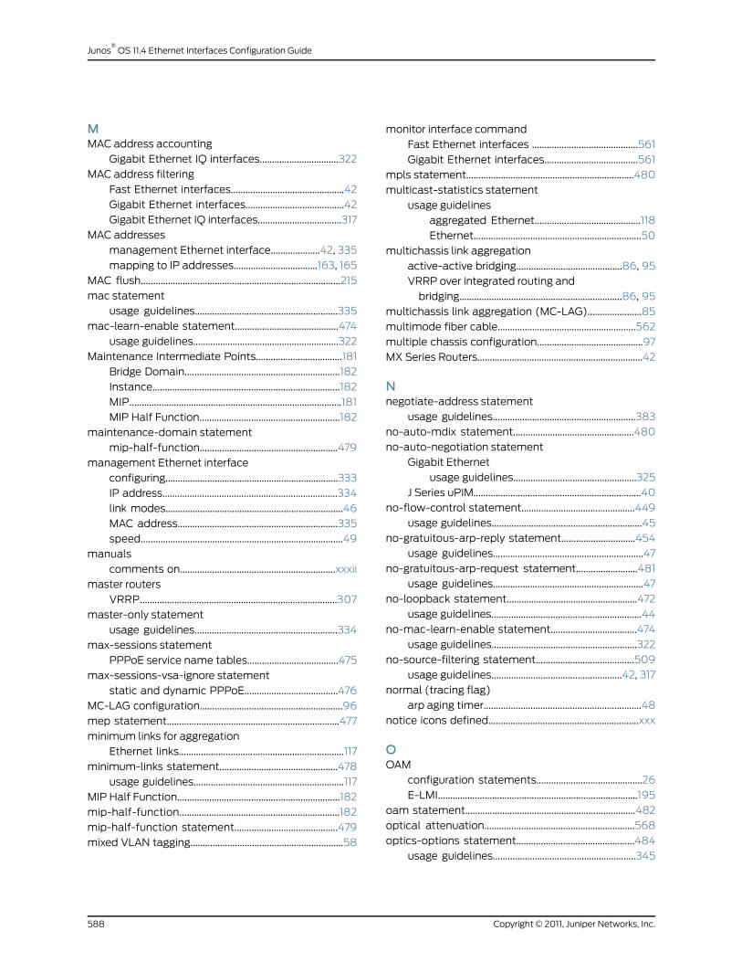
MMAC address accounting
Gigabit Ethernet IQ interfaces................................322
MAC address filtering
Fast Ethernet interfaces..............................................42
Gigabit Ethernet interfaces........................................42
Gigabit Ethernet IQ interfaces..................................317
MAC addresses
management Ethernet interface....................42, 335
mapping to IP addresses..................................163, 165
MAC flush.................................................................................215
mac statement
usage guidelines..........................................................335
mac-learn-enable statement..........................................474
usage guidelines...........................................................322
Maintenance Intermediate Points...................................181
Bridge Domain...............................................................182
Instance............................................................................182
MIP......................................................................................181
MIP Half Function.........................................................182
maintenance-domain statement
mip-half-function........................................................479
management Ethernet interface
configuring......................................................................333
IP address.......................................................................334
link modes........................................................................46
MAC address.................................................................335
speed..................................................................................49
manuals
comments on...............................................................xxxii
master routers
VRRP................................................................................307
master-only statement
usage guidelines..........................................................334
max-sessions statement
PPPoE service name tables.....................................475
max-sessions-vsa-ignore statement
static and dynamic PPPoE......................................476
MC-LAG configuration..........................................................96
mep statement......................................................................477
minimum links for aggregation
Ethernet links...................................................................117
minimum-links statement................................................478
usage guidelines.............................................................117
MIP Half Function..................................................................182
mip-half-function.................................................................182
mip-half-function statement..........................................479
mixed VLAN tagging..............................................................58
monitor interface command
Fast Ethernet interfaces ...........................................561
Gigabit Ethernet interfaces......................................561
mpls statement....................................................................480
multicast-statistics statement
usage guidelines
aggregated Ethernet...........................................118
Ethernet....................................................................50
multichassis link aggregation
active-active bridging...........................................86, 95
VRRP over integrated routing and
bridging..................................................................86, 95
multichassis link aggregation (MC-LAG)......................85
multimode fiber cable........................................................562
multiple chassis configuration...........................................97
MX Series Routers...................................................................42
Nnegotiate-address statement
usage guidelines..........................................................383
no-auto-mdix statement.................................................480
no-auto-negotiation statement
Gigabit Ethernet
usage guidelines..................................................325
J Series uPIM....................................................................40
no-flow-control statement..............................................449
usage guidelines.............................................................45
no-gratuitous-arp-reply statement..............................454
usage guidelines.............................................................47
no-gratuitous-arp-request statement.........................481
usage guidelines.............................................................47
no-loopback statement.....................................................472
usage guidelines.............................................................44
no-mac-learn-enable statement...................................474
usage guidelines...........................................................322
no-source-filtering statement........................................509
usage guidelines.....................................................42, 317
normal (tracing flag)
arp aging timer................................................................48
notice icons defined.............................................................xxx
OOAM
configuration statements...........................................26
E-LMI.................................................................................195
oam statement.....................................................................482
optical attenuation.............................................................568
optics-options statement................................................484
usage guidelines..........................................................345
Copyright © 2011, Juniper Networks, Inc.588
Junos®
OS 11.4 Ethernet Interfaces Configuration Guide
output-priority-map statement.....................................485
usage guidelines...........................................................315
output-vlan-map statement
usage guidelines...........................................................125
Ppackets (tracing flag)...........................................................48
parentheses, in syntax descriptions.............................xxxii
passive monitoring flow
Ethernet interfaces.......................................................173
passive statement
usage guidelines...........................................................109
passive-monitor-mode statement
usage guidelines............................................................173
pdu-interval statement.....................................................485
pdu-threshold statement.................................................486
periodic statement..............................................................487
usage guidelines............................................................110
physical interfaces
Ethernet link aggregation............................................83
flow control......................................................................45
link modes........................................................................46
loopback mode..............................................................44
MAC address filtering...................................................42
mixed VLAN tagging.....................................................58
VLAN tagging................................................53, 159, 537
physical link down
Fast Ethernet interfaces, table..............................568
Gigabit Ethernet interfaces, table.........................568
physical link up
Fast Ethernet interfaces..................................557, 567
Gigabit Ethernet interfaces............................558, 567
physical loopback
Fast Ethernet interfaces...........................................565
Gigabit Ethernet interfaces.....................................565
ping interface command
Fast Ethernet interfaces............................................570
Gigabit Ethernet interfaces .....................................570
policer statement
CFM firewall..................................................................488
CFM global level..........................................................489
CFM session level.......................................................490
CoS....................................................................................491
interface MAC...............................................................492
usage guidelines...........................................................313
policing
Gigabit Ethernet IQ interfaces........................313, 314
pop statement
Gigabit Ethernet IQ interfaces................................493
Gigabit Ethernet, IQ, IQ2 and IQ2-E interfaces
usage guidelines...................................................125
usage guidelines...........................................................135
pop-pop statement
Gigabit Ethernet IQ interfaces................................493
usage guidelines...........................................................135
pop-swap statement
Gigabit Ethernet IQ interfaces................................494
usage guidelines...........................................................136
Port-Based Network Access Control Protocol
IEEE 802.1x
dot1x........................................................................283
port-status-tlv statement................................................494
ppp-options statement.....................................................495
PPPoE
discovery stage.............................................................374
example configuration....................................386, 387
flags for tracing operations......................................401
log file access for tracing operations....................401
log file size and number...........................................400
log filenames for tracing operations...................400
regular expressions for tracing operations.........401
service name tables
about........................................................................374
ACI/ARI pair configuration...............................393
ACI/ARI pairs.........................................................376
any service configuration..................................391
assigning to underlying interface.................396
benefits...................................................................379
configuration example......................................397
configuration overview.....................................388
configuration troubleshooting.......................401
creating..................................................................389
dynamic PPPoE interfaces..............................377
empty service configuration..........................390
enabling PADO advertisement.....................396
evaluation order for matching client
information.......................................................379
maximum sessions limit.........................377, 394
named service configuration..........................392
PADO advertisement.........................................378
service entries and actions..............................375
static interfaces, reserving..............................395
static PPPoE interfaces....................................378
verifying the configuration..............................403
tracing operations.......................................................399
589Copyright © 2011, Juniper Networks, Inc.
Index
PPPoE client
example configuration..............................................386
reserving static interfaces for.................................395
PPPoE server
example configuration...............................................387
pppoe-options statement...............................................496
usage guidelines..........................................................383
pppoe-underlying-options statement
static and dynamic PPPoE......................................497
premium
policer..............................................................................499
premium statement
hierarchical policer.....................................................498
output priority map....................................................499
usage guidelines..........................................313, 314, 315
Proactive mode
overview..........................................................................242
protection-group
configuration statements...........................................30
protection-group statement...........................................500
protocol-down statement.................................................501
protocols connections
configuration statements....................................24, 29
protocols dot1x
configuration statements...........................................25
protocols Ethernet Ring Protection
configuration statements...........................................30
protocols iccp
configuration statements...........................................25
protocols OAM
configuration statements...........................................26
protocols VRRP
configuration statements...........................................26
proxy statement
usage guidelines............................................................161
proxy-arp statement
usage guidelines...........................................................165
ptopo-configuration-maximum-hold-time
statement............................................................................501
ptopo-configuration-trap-interval statement..........502
push statement
Gigabit Ethernet IQ interfaces................................502
Gigabit Ethernet, IQ, IQ2 and IQ2-E interfaces
usage guidelines...................................................125
usage guidelines...........................................................134
push-push statement
Gigabit Ethernet IQ interfaces................................503
usage guidelines............................................................137
Rremote MEP with iterator profile
configuration.................................................................246
remote statement
usage guidelines............................................67, 159, 161
remote-mep statement....................................................504
request statement...............................................................504
rewrite VLAN tag on untagged frame
usage guidelines...........................................................139
rewrite-on-egress statement
usage guidelines...........................................................125
rewrite-on-ingress statement
usage guidelines...........................................................125
ring-protection-link-end statement.............................505
ring-protection-link-owner statement........................505
RJ-45 Ethernet interface...................................................565
Ssa-multicast statement....................................................506
service ID configuration........................................................97
service name tables
PPPoE
about........................................................................374
ACI/ARI pair configuration...............................393
ACI/ARI pairs.........................................................376
any service configuration..................................391
assigning to underlying interface.................396
benefits...................................................................379
configuration example......................................397
configuration overview.....................................388
configuration troubleshooting.......................401
creating..................................................................389
dynamic PPPoE interfaces..............................377
empty service configuration..........................390
enabling PADO advertisement.....................396
evaluation order for matching client
information.......................................................379
maximum sessions limit.........................377, 394
named service configuration..........................392
PADO advertisement.........................................378
service entries and actions..............................375
static interfaces, reserving..............................395
static PPPoE interfaces....................................378
verifying the configuration..............................403
service-level agreement measurement
overview..........................................................................234
service-name statement
usage guidelines..........................................................383
Copyright © 2011, Juniper Networks, Inc.590
Junos®
OS 11.4 Ethernet Interfaces Configuration Guide

set arp command
Fast Ethernet interfaces ..........................................569
Gigabit Ethernet interfaces.....................................569
set cli terminal command
Fast Ethernet interfaces ..........................................562
Gigabit Ethernet interfaces .....................................562
set loopback local command
Fast Ethernet interfaces ..........................................566
Gigabit Ethernet interfaces ....................................566
short-cycle-protection statement
static and dynamic PPPoE......................................507
show interfaces command..............................................569
Fast Ethernet interfaces .........................557, 567, 571
Gigabit Ethernet interfaces ...........................557, 567
show interfaces extensive command
Fast Ethernet interfaces..................................558, 573
Gigabit Ethernet interfaces.....................................558
show interfaces terse command
Fast Ethernet interfaces ..........................................555
Gigabit Ethernet interfaces.....................................556
single-mode fiber cable.....................................................562
sla-iterator-profile statement
usage guidelines..........................................................246
sonet-options statement
usage guidelines..........................................................369
source address filtering
Fast Ethernet interfaces.......................................42, 43
Gigabit Ethernet interfaces.................................42, 43
source-address-filter statement...................................508
usage guidelines.............................................................43
source-filtering statement...............................................509
usage guidelines.....................................................42, 317
specifications for fiber-optic, table...............................562
Specifying the Interface Over Which VPN Traffic
Travels to the CE Router..................................................70
Specifying the Interface to Handle Traffic for a
CCC............................................................................................71
Specifying the Interface to Handle Traffic for a CCC
Connected to the Layer 2 Circuit...................................72
speed statement
Ethernet...........................................................................510
MX Series DPC................................................................511
usage guidelines.............................................................49
stacked VLAN-tag framing
VLAN ID list.....................................................................541
stacked-vlan-tagging statement
usage guidelines...........................................................125
startup-silent-period statement
usage guidelines..........................................................308
state (tracing flag).................................................................48
static address resolution protocol................................568
static ARP table entries
Ethernet interfaces.............................................163, 165
example configuration...............................................164
static PPPoE statements
max-sessions-vsa-ignore.........................................476
pppoe-underlying-options......................................497
short-cycle-protection..............................................507
static subscribers
max-sessions-vsa-ignore statement..................476
pppoe-underlying-options statement................497
short-cycle-protection statement........................507
statistic error
Fast Ethernet interfaces.............................................571
statistics
Fast Ethernet interfaces ...........................................561
resetting.................................................................570
Gigabit Ethernet interfaces .....................................561
resetting.................................................................570
status
Fast Ethernet interfaces..................................555, 567
Gigabit Ethernet interfaces .....................................567
status description, table
Fast Ethernet interfaces...........................................556
Gigabit Ethernet interfaces.....................................556
status extensive
Fast Ethernet interfaces...........................................558
Gigabit Ethernet interfaces ....................................558
status for specific interface
Fast Ethernet.................................................................557
Gigabit Ethernet ..........................................................557
STM1 interfaces
example configuration..............................................369
subscriber interface statements
max-sessions-vsa-ignore.........................................476
pppoe-underlying-options......................................497
short-cycle-protection..............................................507
support, technical See technical support
swap statement
Gigabit Ethernet IQ interfaces.................................512
Gigabit Ethernet, IQ, IQ2 and IQ2-E interfaces
usage guidelines...................................................125
swap-push statement
Gigabit Ethernet IQ interfaces.................................512
usage guidelines...........................................................142
swap-swap statement
Gigabit Ethernet IQ interfaces.................................513
usage guidelines...........................................................142
591Copyright © 2011, Juniper Networks, Inc.
Index

switch-options statement.................................................513
switch-port statement
access switching...........................................................514
Symmetrical Load Balancing
on 802.3ad Link Aggregation on MX
Series............................................................................120
syntax conventions..............................................................xxxi
Ttag-protocol-id statement................................................515
TPID to rewrite..............................................................516
TPIDs expected to be sent or received................515
usage guidelines....................................................125, 131
technical support
contacting JTAC..........................................................xxxii
timer (tracing flag)
Ethernet interface speed............................................48
trace operations
VRRP..................................................................................48
traceoptions (LACP) statement
usage guidelines............................................................113
traceoptions statement
LLDP...................................................................................517
usage guidelines..................................................156
VRRP
usage guidelines....................................................48
tracing operations
LACP...................................................................................113
LLDP.........................................................................156, 517
PPPoE..............................................................................399
transmit light level...............................................................562
transmit-delay statement
LLDP..................................................................................519
Tri-Rate Ethernet copper interfaces
speed..................................................................................49
trunk interface
interface-mode statement.........................................76
usage guidelines..............................................................77
vlan-id-list statement...................................................77
trunk port....................................................................................77
VLAN ID list....................................................................532
Uunit statement......................................................................520
unnumbered-interface statement
usage guidelines..........................................................383
uPIM Ethernet interfaces.....................................................40
VVirtual Router Redundancy Protocol See VRRP
VLAN
Configuring a Layer 2 Circuit on a
VLAN-Bundled Logical Interface..........................71
Configuring a VLAN-Bundled Logical
Interface..........................................................................71
Configuring Logical Link-Layer Encapsulation
to Support CCCs........................................................69
Configuring VLAN ID List-Bundled Logical
Interfaces That Connect CCCs.............................68
Specifying the Interface Over Which VPN
Traffic Travels to the CE Router............................70
Specifying the Interface to Handle Traffic for a
CCC...................................................................................71
VLAN CCC
configuration guidelines..............................................65
example configuration.................................................66
VLAN IDs..................................................................................533
values, listed by Ethernet interface type...............55
VLAN tag stacking and rewriting
Gigabit Ethernet, IQ, IQ2 and IQ2-E
interfaces.....................................................................125
VLAN tagging.........................................................53, 159, 537
VLAN VPLS
configuration guidelines..............................................65
example configuration.................................................66
vlan-id statement.................................................................527
802.1Q VLANs...............................................................528
ATM-to-Ethernet cross-connect...........................528
Ethernet interfaces.....................................................528
usage guidelines...........................................53, 159
Fast Ethernet interfaces
usage guidelines...........................................53, 159
Gigabit Ethernet interfaces
usage guidelines............................................59, 64
interface in bridge domain........................................527
rewriting at ingress or egress..................................529
usage guidelines...........................................................125
vlan-id-list..............................................................................530
vlan-id-list statement
bridge domain...............................................................532
Ethernet VLAN circuit.................................................531
Gigabit Ethernet interfaces
usage guidelines....................................................59
usage guidelines..............................................................77
Copyright © 2011, Juniper Networks, Inc.592
Junos®
OS 11.4 Ethernet Interfaces Configuration Guide

vlan-id-range statement...................................................533
Ethernet interfaces.....................................................533
Gigabit Ethernet interfaces
usage guidelines....................................................59
vlan-ranges statement......................................................534
vlan-rewrite statement......................................................535
vlan-rule statement............................................................535
vlan-steering statement....................................................536
vlan-tagging statement.....................................................537
Ethernet interfaces
usage guidelines...........................................53, 159
Fast Ethernet interfaces
usage guidelines...........................................53, 159
Gigabit Ethernet interfaces
usage guidelines....................................................53
vlan-tags statement
dual-tag framing.........................................................539
Gigabit Ethernet interfaces
usage guidelines....................................................64
stacked VLAN tags......................................................541
usage guidelines...........................................................130
vlan-tags-outer statement...............................................542
vlan-vci-tagging statement.............................................542
VLANs
configuring VLAN ranges..........................................534
VPLS
statistical frame loss measurement.....................247
VRRP.........................................................................................307
configuration statements...........................................26
trace operations.............................................................48
tracing flag.......................................................................48
VRRP over integrated routing and bridging..........86, 95
WWAN PHY
configuring......................................................................347
wavelength statement.......................................................543
usage guidelines..........................................................345
weighted random early detection.....................................51
west-interface statement................................................546
working-circuit statement.................................................547
WRED...........................................................................................51
593Copyright © 2011, Juniper Networks, Inc.
Index

Copyright © 2011, Juniper Networks, Inc.594
Junos®
OS 11.4 Ethernet Interfaces Configuration Guide

Index ofStatements andCommands
Symbols802.3ad statement.............................................................433
Aadvertisement-interval statement................................434
aggregated-ether-options statement.........................435
auto-negotiation statement
Gigabit Ethernet...........................................................437
Bbandwidth-limit statement
policer for Gigabit Ethernet interface..................438
burst-size-limit statement
policer for Gigabit Ethernet interface..................439
Cclassifier statement............................................................439
Ddisable statement
LLDP................................................................................440
dynamic PPPoE statements
max-sessions-vsa-ignore.........................................476
pppoe-underlying-options......................................497
short-cycle-protection..............................................507
Eethernet statement..............................................................441
ethernet-policer-profile statement..............................444
ethernet-ring statement...................................................445
ethernet-switch-profile statement.....................318, 446
event statement
port-status-tlv statement.......................................494
Ffastether-options statement...........................................447
flow-control statement.....................................................449
flow-control-options statement...................................450
fnp statement
Ethernet OAM...............................................................448
forwarding-mode statement............................................451
framing statement
10-Gigabit Ethernet interfaces...............................452
Ggigether-options statement.............................................453
gratuitous-arp-reply statement.....................................454
Hhold-multiplier statement................................................455
Iieee802.1p statement........................................................455
ignore-l3-incompletes statement.................................456
ingress-rate-limit statement...........................................456
inner-tag-protocol-id statement....................................457
inner-vlan-id statement....................................................458
inner-vlan-id-range statement.......................................459
input-priority-map statement........................................459
input-vlan-map statement.............................................460
interface statement
LLDP.................................................................................462
interfaces statement..........................................................463
Llacp statement
802.3ad..........................................................................464
Aggregated Ethernet.................................................465
link-discovery statement..................................................466
link-fault-management statement...............................467
link-mode statement.........................................................468
link-protection statement................................................469
lldp statement
LLDP..................................................................................471
lldp-configuration-notification-interval
statement............................................................................472
loopback statement
Aggregated Ethernet, Fast Ethernet, and Gigabit
Ethernet......................................................................472
loss-priority statement.......................................................473
Mmac-learn-enable statement..........................................474
maintenance-domain statement
mip-half-function........................................................479
595Copyright © 2011, Juniper Networks, Inc.
max-sessions statement
PPPoE service name tables.....................................475
max-sessions-vsa-ignore statement
static and dynamic PPPoE......................................476
mep statement......................................................................477
minimum-links statement................................................478
mip-half-function statement..........................................479
mpls statement....................................................................480
Nno-auto-mdix statement.................................................480
no-flow-control statement..............................................449
no-gratuitous-arp-reply statement..............................454
no-gratuitous-arp-request statement.........................481
no-loopback statement.....................................................472
no-mac-learn-enable statement...................................474
no-source-filtering statement........................................509
Ooam statement.....................................................................482
optics-options statement................................................484
output-priority-map statement.....................................485
Ppdu-interval statement.....................................................485
pdu-threshold statement.................................................486
periodic statement..............................................................487
policer statement
CFM firewall..................................................................488
CFM global level..........................................................489
CFM session level.......................................................490
CoS....................................................................................491
interface MAC...............................................................492
pop statement
Gigabit Ethernet IQ interfaces................................493
pop-pop statement
Gigabit Ethernet IQ interfaces................................493
pop-swap statement
Gigabit Ethernet IQ interfaces................................494
port-status-tlv statement................................................494
ppp-options statement.....................................................495
pppoe-options statement...............................................496
pppoe-underlying-options statement
static and dynamic PPPoE......................................497
premium
policer..............................................................................499
premium statement
hierarchical policer.....................................................498
output priority map....................................................499
protection-group statement...........................................500
protocol-down statement.................................................501
ptopo-configuration-maximum-hold-time
statement............................................................................501
ptopo-configuration-trap-interval statement..........502
push statement
Gigabit Ethernet IQ interfaces................................502
push-push statement
Gigabit Ethernet IQ interfaces................................503
Rremote-mep statement....................................................504
request statement...............................................................504
ring-protection-link-end statement.............................505
ring-protection-link-owner statement........................505
Ssa-multicast statement....................................................506
short-cycle-protection statement
static and dynamic PPPoE......................................507
sla-iterator-profile statement
usage guidelines..........................................................246
source-address-filter statement...................................508
source-filtering statement...............................................509
speed statement
Ethernet...........................................................................510
MX Series DPC................................................................511
static PPPoE statements
max-sessions-vsa-ignore.........................................476
pppoe-underlying-options......................................497
short-cycle-protection..............................................507
subscriber interface statements
max-sessions-vsa-ignore.........................................476
pppoe-underlying-options......................................497
short-cycle-protection..............................................507
swap statement
Gigabit Ethernet IQ interfaces.................................512
swap-push statement
Gigabit Ethernet IQ interfaces.................................512
swap-swap statement
Gigabit Ethernet IQ interfaces.................................513
switch-options statement.................................................513
switch-port statement
access switching...........................................................514
Ttag-protocol-id statement................................................515
TPID to rewrite..............................................................516
TPIDs expected to be sent or received................515
Copyright © 2011, Juniper Networks, Inc.596
Junos®
OS 11.4 Ethernet Interfaces Configuration Guide
traceoptions statement
LLDP...................................................................................517
transmit-delay statement
LLDP..................................................................................519
Uunit statement......................................................................520
Vvlan-id statement.................................................................527
802.1Q VLANs...............................................................528
ATM-to-Ethernet cross-connect...........................528
Ethernet interfaces.....................................................528
interface in bridge domain........................................527
rewriting at ingress or egress..................................529
vlan-id-list..............................................................................530
vlan-id-list statement
bridge domain...............................................................532
Ethernet VLAN circuit.................................................531
vlan-id-range statement...................................................533
vlan-ranges statement......................................................534
vlan-rewrite statement......................................................535
vlan-rule statement............................................................535
vlan-steering statement....................................................536
vlan-tagging statement.....................................................537
vlan-tags statement
dual-tag framing.........................................................539
stacked VLAN tags......................................................541
vlan-tags-outer statement...............................................542
vlan-vci-tagging statement.............................................542
Wwavelength statement.......................................................543
west-interface statement................................................546
working-circuit statement.................................................547
597Copyright © 2011, Juniper Networks, Inc.
Index of Statements and Commands

Copyright © 2011, Juniper Networks, Inc.598
Junos®
OS 11.4 Ethernet Interfaces Configuration Guide