Embed Size (px)
DESCRIPTION
about optical fibre
Citation preview
Ethernet training
Section 1 – Why Deploy Ethernet?
1.1 Background
Years ago, voice service drove the design and deployment of wide area networksthroughout the world. Over the past 10 years this has changed. The desire forinformation across the country and across the globe has lead to a focus on next generationdata networks in the wide area.
Initial data deployments were at low speeds and with low reliability. Typical rates werebetween 9.6 kb/s and 64 kb/s running X.25. The customer, in this case, owned the dataservice, with the provider owning the pipe.
Next generation services allowed the carrier to offer the pipe as well as the data service,offering more revenue to the carrier and more flexibility and support to the customer.The first data services were bases on the SMDS standard. Speeds were still slow, but theservice was more reliable.
The next step in data service is our current position. Technologies such as frame relayand ATM lead the way for customers to spread their data across the globe. Speeds are nolonger limited to 64kb/s. A customer can purchase data services from 64kb/s up to2.4Gbs and higher. Point-to-point or point-to-multi point services are available.
As well as ATM and frame relay, carriers are now offering Ethernet to their customers.Why would a customer want to go to Ethernet instead of staying with their existing framerelay or ATM data services?
Frame relay, a technology designed to carry data, is not widely available above a T1(1.544Mbs). In some areas, as much as a DS3 (45Mbs) frame relay pipe can be ordered.ATM offers a wider range of speeds, T1 (1.544Mbs) to an OC-12 (622Mbs), but is not asefficient with data as frame relay. ATM was designed to carry voice, video, and data allon one pipe. This added functionality adds a lot of overhead to the data stream.
Ethernet offers a range of speeds and is focused solely on data. Ethernet allows thecustomer to save time and money by not having to buy expensive routers to convert theirLAN traffic to a WAN technology. With the wide scale carrier based deployment ofEthernet, customers will be able to buy Ethernet pipes ranging from 10 Mb/s through1Gb/s. In the near future, the next generation of Ethernet will be available running at10Gb/s.
1.2 Ethernet’s CapabilitiesThe benefit of Ethernet, and its main reason to exist, is that it handles data trafficextremely well. Various technologies such as Appletalk, DECnet, TCP/IP, and IPX(Novell) are equally handled and transported by Ethernet. LAN administrators could
build a network with all of these technologies running simultaneously and Ethernet couldhandle the task.
In today’s LAN environment, there are two main types of technologies that exist withEthernet – IPX and IP. IPX is Novell’s technology designed mainly to manage printers,servers, and access to mainframes. This technology typically resides on a LAN and doesnot often traverse the wide area network. It is not often that a person in Atlanta, forexample, will want to print a document in their New York office. It is more likely theywill print it locally and fax it, if necessary.
IP (Internet Protocol) represents the bulk to the traffic that traverses Ethernet networks.This is the addressing scheme that enables the Internet and many other technologiesaround the globe to work together. IP is the main driver to Ethernet’s growth. Since IPwas created initially to support the Internet, it is critical to understand the history of theInternet.
1.3 Internet HistoryToday’s Internet was created in 1969 through a government-sponsored project calledARPANET (Advanced Research Projects Agency Network). The purpose of ARPANETwas to test and determine the viability of packet switched networks. The firstdeployment of ARPANET was at four separate locations: Stanford Research Institute, theUniversity of California at Santa Barbara, the University of California at Los Angeles,and the University of Utah.
The initial tests went well and ARPANET grew. It had become obvious to theresearchers that non-military as well as military personnel could benefit from a large,interconnected network. It was also clear that a more reliable set of protocols wasrequired to handle the ever-growing network. In 1973, ARPANET added IP, TCP, UDP,and ICMP (Ping) to the list of supported protocols. This allowed traffic to be handledquickly and easily by the end stations. It also offered error correction and retransmissionof lost data. In 1981, the NSF (National Science Foundation) approved funds for theComputer Science Network (CSNET). This network allowed both university andindustry to share information.
In 1984 ARPANET was split into two different networks – one for military and one fornon-military traffic. At the same time, the NSF expanded its funding and establishedNSFNET. NSFNET connected six supercomputers together with high-speed lines –much faster than ARPANET. Because of this, ARPANET became obsolete, and wasdismantled in the very early 1990s.
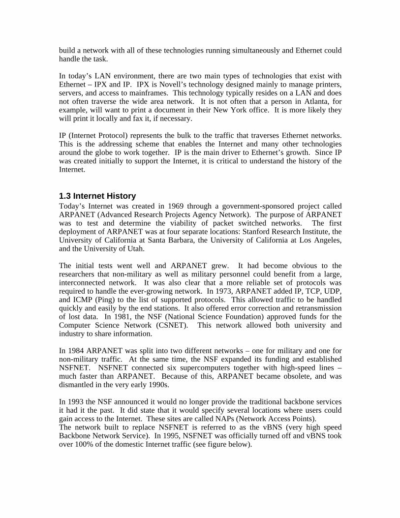
In 1993 the NSF announced it would no longer provide the traditional backbone servicesit had it the past. It did state that it would specify several locations where users couldgain access to the Internet. These sites are called NAPs (Network Access Points).The network built to replace NSFNET is referred to as the vBNS (very high speedBackbone Network Service). In 1995, NSFNET was officially turned off and vBNS tookover 100% of the domestic Internet traffic (see figure below).
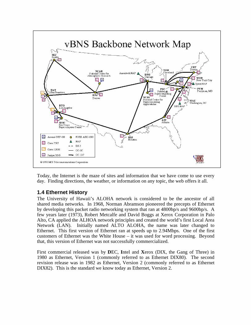
Today, the Internet is the maze of sites and information that we have come to use everyday. Finding directions, the weather, or information on any topic, the web offers it all.
1.4 Ethernet HistoryThe University of Hawaii’s ALOHA network is considered to be the ancestor of allshared media networks. In 1968, Norman Abramson pioneered the precepts of Ethernetby developing this packet radio networking system that ran at 4800bp/s and 9600bp/s. Afew years later (1973), Robert Metcalfe and David Boggs at Xerox Corporation in PaloAlto, CA applied the ALHOA network principles and created the world’s first Local AreaNetwork (LAN). Initially named ALTO ALOHA, the name was later changed toEthernet. This first version of Ethernet ran at speeds up to 2.94Mbps. One of the firstcustomers of Ethernet was the White House – it was used for word processing. Beyondthat, this version of Ethernet was not successfully commercialized.
First commercial released was by DEC, Intel and Xerox (DIX, the Gang of Three) in1980 as Ethernet, Version 1 (commonly referred to as Ethernet DIX80). The secondrevision release was in 1982 as Ethernet, Version 2 (commonly referred to as EthernetDIX82). This is the standard we know today as Ethernet, Version 2.
In 1980, the IEEE formed its Project 802 to provide a framework for the standardizationof LAN technology. Novell released Novell Netware ’86 in 1983, which used aproprietary frame format based on a preliminary specification of the IEEE 802.3specification. This is the same Novell that is used today to manage printers and servers.
In 1983, the IEEE approved the IEEE 802.3 specification, which included IEEE 802.2Logical Link Control (LLC). This made the Novell Netware proprietary formatincompatible with the latest technology. In order to resolve this incompatibility, SNAPwas created for the new IEEE 802.3.
Now that the overall packet standards were finished, the transmission medium needed tobe agreed on. In the late 1980s, SynOptics Communications developed a mechanism fortransmitting 10Mbps Ethernet signals over twisted-pair cables. It was this combinationof low cost transmission medium with an agreed standard that led to the wide deploymentof Ethernet.
The Ethernet-over-twisted-pair standard (10BASE-T) was approved by the IEEE in 1990as the IEEE 802.3i standard and quickly became the preferred Ethernet media type.
1.5 SummaryNext generation services such as managed IP and voice over IP, will require morebandwidth that is optimized for data. Ethernet is the technology that will allowcustomers access to higher speeds optimized for data.
Since Ethernet is a mature technology, is built around a solid standard, is optimized fornext generation data services, and is cheap to deploy, Ethernet demand from servicesproviders will grow tremendously over the next decade.
Section 2 - Technology OverviewBy understanding a few basic concepts, Ethernet and Ethernet turn-up/troubleshootingwill be easily within your grasp. The following sections are focused on that goal.
2.1 OSI ModelThe ISO (International Standards Organization) designed the OSI (Open SystemInterconnect) model for data communications. This model, in some form, is followed byALL data communications. Any time two or more computers pass information, theyfollow the OSI model.
The model (shown below) is a series of basic building blocks. Each block has its ownfunction and role in getting data from one point to another point.
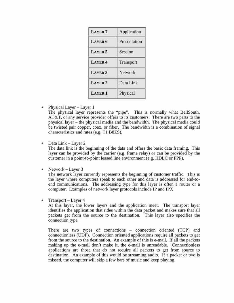
LAYER 7 Application
LAYER 6 Presentation
LAYER 5 Session
LAYER 4 Transport
LAYER 3 Network
LAYER 2 Data Link
LAYER 1 Physical
• Physical Layer – Layer 1The physical layer represents the “pipe”. This is normally what BellSouth,AT&T, or any service provider offers to its customers. There are two parts to thephysical layer – the physical media and the bandwidth. The physical media couldbe twisted pair copper, coax, or fiber. The bandwidth is a combination of signalcharacteristics and rates (e.g. T1 B8ZS).
• Data Link – Layer 2The data link is the beginning of the data and offers the basic data framing. Thislayer can be provided by the carrier (e.g. frame relay) or can be provided by thecustomer in a point-to-point leased line environment (e.g. HDLC or PPP).
• Network – Layer 3The network layer currently represents the beginning of customer traffic. This isthe layer where computers speak to each other and data is addressed for end-to-end communications. The addressing type for this layer is often a router or acomputer. Examples of network layer protocols include IP and IPX
• Transport – Layer 4At this layer, the lower layers and the application meet. The transport layeridentifies the application that rides within the data packet and makes sure that allpackets get from the source to the destination. This layer also specifies theconnection type.
There are two types of connections – connection oriented (TCP) andconnectionless (UDP). Connection oriented applications require all packets to getfrom the source to the destination. An example of this is e-mail. If all the packetsmaking up the e-mail don’t make it, the e-mail is unreadable. Connectionlessapplications are those that do not require all packets to get from source todestination. An example of this would be streaming audio. If a packet or two ismissed, the computer will skip a few bars of music and keep playing.
• Session, Presentation, and Application – Layers 5, 6, and 7In most data communication networks today, these layers merge together into justthe application. Aspects of Lotus Notes, POP3 mail, SMTP mail, and web surfingall have layers 5, 6, and 7 built into them. For purposes of this training class, wewill combine these layers together into only layer 7 and refer to this as theapplication layer.
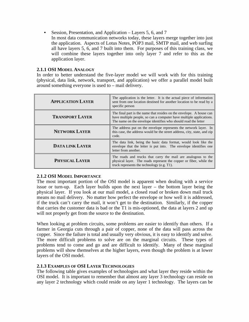
2.1.1 OSI MODEL ANALOGYIn order to better understand the five-layer model we will work with for this training(physical, data link, network, transport, and application) we offer a parallel model builtaround something everyone is used to – mail delivery.
APPLICATION LAYERThe application is the letter. It is the actual piece of informationsent from one location destined for another location to be read by aspecific person
TRANSPORT LAYERThe final part is the name that resides on the envelope. A house canhave multiple people, so can a computer have multiple applications.The name on the envelope identifies who should read the letter
NETWORK LAYERThe address put on the envelope represents the network layer. Inthis case, the address would be the street address, city, state, and zipcode.
DATA LINK LAYERThe data link, being the basic data format, would look like theenvelope that the letter is put into. The envelope identifies oneletter from another.
PHYSICAL LAYERThe roads and trucks that carry the mail are analogous to thephysical layer. The roads represent the copper or fiber, while thetruck represents the technology (e.g. T1).
2.1.2 OSI MODEL IMPORTANCEThe most important portion of the OSI model is apparent when dealing with a serviceissue or turn-up. Each layer builds upon the next layer – the bottom layer being thephysical layer. If you look at our mail model, a closed road or broken down mail truckmeans no mail delivery. No matter how perfect the envelope or how well it is addressed,if the truck can’t carry the mail, it won’t get to the destination. Similarly, if the copperthat carries the customer data is bad or the T1 is mis-optioned, the data at layers 2 and upwill not properly get from the source to the destination.
When looking at problem circuits, some problems are easier to identify than others. If afarmer in Georgia cuts through a pair of copper, none of the data will pass across thecopper. Since the failure is total and usually very obvious, it is easy to identify and solve.The more difficult problems to solve are on the marginal circuits. These types ofproblems tend to come and go and are difficult to identify. Many of these marginalproblems will show themselves at the higher layers, even though the problem is at lowerlayers of the OSI model.
2.1.3 EXAMPLES OF OSI LAYER TECHNOLOGIESThe following table gives examples of technologies and what layer they reside within theOSI model. It is important to remember that almost any layer 3 technology can reside onany layer 2 technology which could reside on any layer 1 technology. The layers can be
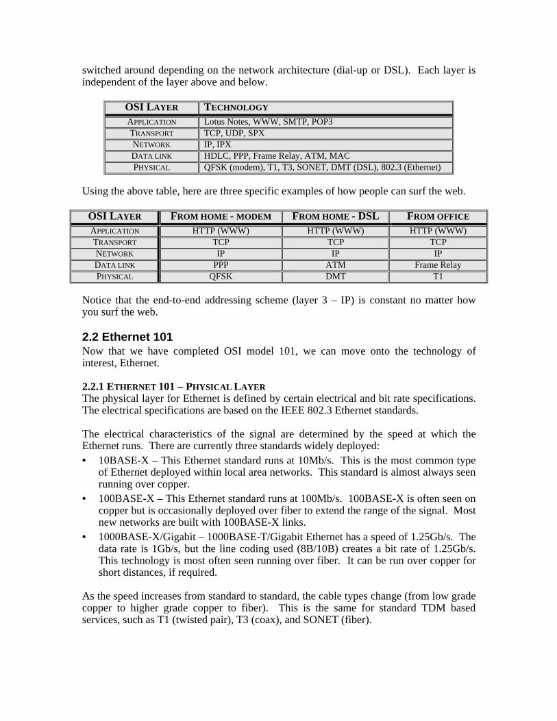
switched around depending on the network architecture (dial-up or DSL). Each layer isindependent of the layer above and below.
OSI LAYER TECHNOLOGY
APPLICATION Lotus Notes, WWW, SMTP, POP3TRANSPORT TCP, UDP, SPXNETWORK IP, IPXDATA LINK HDLC, PPP, Frame Relay, ATM, MACPHYSICAL QFSK (modem), T1, T3, SONET, DMT (DSL), 802.3 (Ethernet)
Using the above table, here are three specific examples of how people can surf the web.
OSI LAYER FROM HOME - MODEM FROM HOME - DSL FROM OFFICE
APPLICATION HTTP (WWW) HTTP (WWW) HTTP (WWW)TRANSPORT TCP TCP TCPNETWORK IP IP IPDATA LINK PPP ATM Frame RelayPHYSICAL QFSK DMT T1
Notice that the end-to-end addressing scheme (layer 3 – IP) is constant no matter howyou surf the web.
2.2 Ethernet 101Now that we have completed OSI model 101, we can move onto the technology ofinterest, Ethernet.
2.2.1 ETHERNET 101 – PHYSICAL LAYERThe physical layer for Ethernet is defined by certain electrical and bit rate specifications.The electrical specifications are based on the IEEE 802.3 Ethernet standards.
The electrical characteristics of the signal are determined by the speed at which theEthernet runs. There are currently three standards widely deployed:• 10BASE-X – This Ethernet standard runs at 10Mb/s. This is the most common type
of Ethernet deployed within local area networks. This standard is almost always seenrunning over copper.
• 100BASE-X – This Ethernet standard runs at 100Mb/s. 100BASE-X is often seen oncopper but is occasionally deployed over fiber to extend the range of the signal. Mostnew networks are built with 100BASE-X links.
• 1000BASE-X/Gigabit – 1000BASE-T/Gigabit Ethernet has a speed of 1.25Gb/s. Thedata rate is 1Gb/s, but the line coding used (8B/10B) creates a bit rate of 1.25Gb/s.This technology is most often seen running over fiber. It can be run over copper forshort distances, if required.
As the speed increases from standard to standard, the cable types change (from low gradecopper to higher grade copper to fiber). This is the same for standard TDM basedservices, such as T1 (twisted pair), T3 (coax), and SONET (fiber).
Another important physical layer characteristic of Ethernet is full duplex or half duplexoperation. A full duplex circuit is able to transmit and receive at the same time, similar toa phone where a person can speak and hear at the same time. A half duplex circuit iseither speaking or listening – it is incapable of both simultaneously.
10BASE-X Ethernet is most commonly deployed in a half duplex environment. Becauseof its speed, being the slowest Ethernet speed, this is not a problem. As Ethernet speedsgrew and the bandwidth requirements grew with them, full duplex became more critical.100BASE-X can be seen as a full duplex or half duplex, depending on the bandwidthrequirements.
Gigabit Ethernet, with its high bandwidth capabilities, is almost always seen in a fullduplex configuration. This particular type of Ethernet is what is driving the carrier basedEthernet deployment.
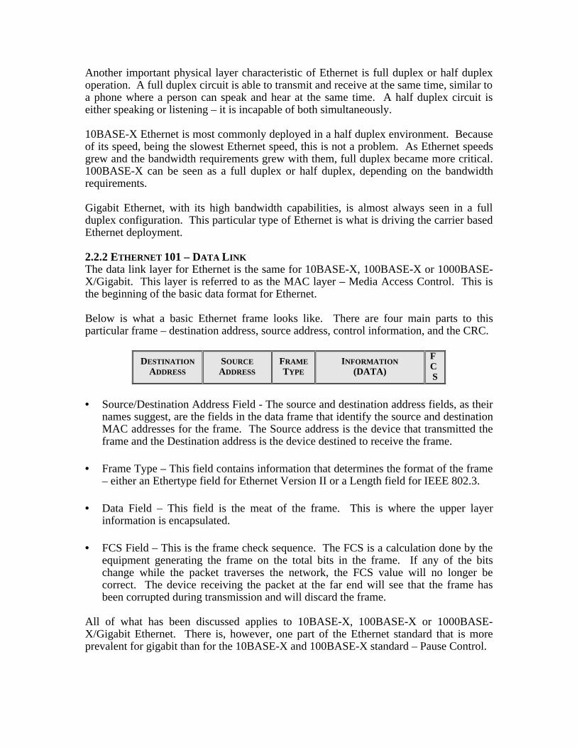
2.2.2 ETHERNET 101 – DATA LINKThe data link layer for Ethernet is the same for 10BASE-X, 100BASE-X or 1000BASE-X/Gigabit. This layer is referred to as the MAC layer – Media Access Control. This isthe beginning of the basic data format for Ethernet.
Below is what a basic Ethernet frame looks like. There are four main parts to thisparticular frame – destination address, source address, control information, and the CRC.
DESTINATIONADDRESS
SOURCEADDRESS
FRAMETYPE
INFORMATION(DATA)
FCS
• Source/Destination Address Field - The source and destination address fields, as theirnames suggest, are the fields in the data frame that identify the source and destinationMAC addresses for the frame. The Source address is the device that transmitted theframe and the Destination address is the device destined to receive the frame.
• Frame Type – This field contains information that determines the format of the frame– either an Ethertype field for Ethernet Version II or a Length field for IEEE 802.3.
• Data Field – This field is the meat of the frame. This is where the upper layerinformation is encapsulated.
• FCS Field – This is the frame check sequence. The FCS is a calculation done by theequipment generating the frame on the total bits in the frame. If any of the bitschange while the packet traverses the network, the FCS value will no longer becorrect. The device receiving the packet at the far end will see that the frame hasbeen corrupted during transmission and will discard the frame.
All of what has been discussed applies to 10BASE-X, 100BASE-X or 1000BASE-X/Gigabit Ethernet. There is, however, one part of the Ethernet standard that is moreprevalent for gigabit than for the 10BASE-X and 100BASE-X standard – Pause Control.
Pause control frames allow Ethernet elements to throttle the actual throughput of the linkreal time. Most elements could support full 10BASE-X and 100BASE-X rates. Whengigabit Ethernet was first released, many elements could not support long durations offull bandwidth routing. Because of this, pause control standard allowed a local elementto tell the far end element to slow down until the local element caught up. Although notas prevalent as a few years ago, this is still part of the Ethernet standard and can be seenin deployed networks.
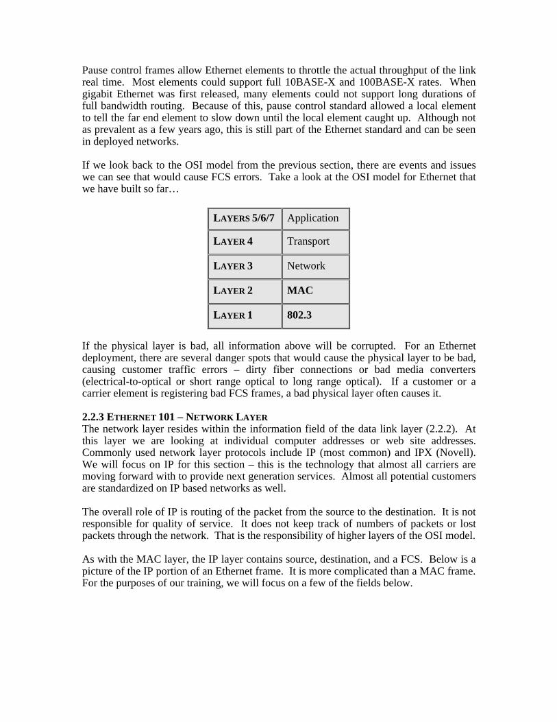
If we look back to the OSI model from the previous section, there are events and issueswe can see that would cause FCS errors. Take a look at the OSI model for Ethernet thatwe have built so far…
LAYERS 5/6/7 Application
LAYER 4 Transport
LAYER 3 Network
LAYER 2 MAC
LAYER 1 802.3
If the physical layer is bad, all information above will be corrupted. For an Ethernetdeployment, there are several danger spots that would cause the physical layer to be bad,causing customer traffic errors – dirty fiber connections or bad media converters(electrical-to-optical or short range optical to long range optical). If a customer or acarrier element is registering bad FCS frames, a bad physical layer often causes it.
2.2.3 ETHERNET 101 – NETWORK LAYERThe network layer resides within the information field of the data link layer (2.2.2). Atthis layer we are looking at individual computer addresses or web site addresses.Commonly used network layer protocols include IP (most common) and IPX (Novell).We will focus on IP for this section – this is the technology that almost all carriers aremoving forward with to provide next generation services. Almost all potential customersare standardized on IP based networks as well.
The overall role of IP is routing of the packet from the source to the destination. It is notresponsible for quality of service. It does not keep track of numbers of packets or lostpackets through the network. That is the responsibility of higher layers of the OSI model.
As with the MAC layer, the IP layer contains source, destination, and a FCS. Below is apicture of the IP portion of an Ethernet frame. It is more complicated than a MAC frame.For the purposes of our training, we will focus on a few of the fields below.
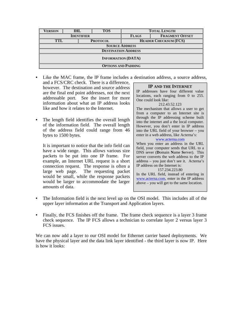
VERSION IHL TOS TOTAL LENGTH
IDENTIFIER FLAGS FRAGMENT OFFSET
TTL PROTOCOL HEADER CHECKSUM (FCS)SOURCE ADDRESS
DESTINATION ADDRESS
INFORMATION (DATA)
OPTIONS AND PADDING
• Like the MAC frame, the IP frame includes a destination address, a source address,and a FCS/CRC check. There is a difference,however. The destination and source addressare the final end point addresses, not the nextaddressable port. See the insert for moreinformation about what an IP address lookslike and how it relates to the Internet.
• The length field identifies the overall lengthof the information field. The overall lengthof the address field could range from 46bytes to 1500 bytes.
It is important to notice that the info field canhave a wide range. This allows various sizepackets to be put into one IP frame. Forexample, an Internet URL request is a shortconnection request. The response is often alarge web page. The requesting packetwould be small, while the response packetswould be larger to accommodate the largeramounts of data.
• The Information field is the next level up on the OSI model. This includes all of theupper layer information at the Transport and Application layers.
• Finally, the FCS finishes off the frame. The frame check sequence is a layer 3 framecheck sequence. The IP FCS allows a technician to correlate layer 2 versus layer 3FCS issues.
We can now add a layer to our OSI model for Ethernet carrier based deployments. Wehave the physical layer and the data link layer identified - the third layer is now IP. Hereis how it looks:
IP AND THE INTERNETIP addresses have four different valuelocations, each ranging from 0 to 255.One could look like:
212.43.52.123The mechanism that allows a user to getfrom a computer to an Internet site isthrough the IP addressing scheme builtinto the internet and a the local computer.However, you don’t enter in IP addressinto the URL field of your browser – youenter in a web address, like Acterna’s:
www.acterna.comWhen you enter an address in the URLfield, your computer sends that URL to aDNS sever (Domain Name Server). Thisserver converts the web address to the IPaddress – you just don’t see it. Acterna’sIP address on the Internet is:
157.234.223.80In the URL field, instead of entering inwww.acterna.com, enter in the IP addressabove – you will get to the same location.
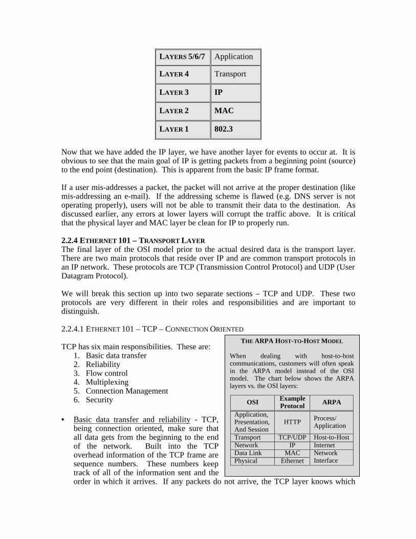
LAYERS 5/6/7 Application
LAYER 4 Transport
LAYER 3 IP
LAYER 2 MAC
LAYER 1 802.3
Now that we have added the IP layer, we have another layer for events to occur at. It isobvious to see that the main goal of IP is getting packets from a beginning point (source)to the end point (destination). This is apparent from the basic IP frame format.
If a user mis-addresses a packet, the packet will not arrive at the proper destination (likemis-addressing an e-mail). If the addressing scheme is flawed (e.g. DNS server is notoperating properly), users will not be able to transmit their data to the destination. Asdiscussed earlier, any errors at lower layers will corrupt the traffic above. It is criticalthat the physical layer and MAC layer be clean for IP to properly run.
2.2.4 ETHERNET 101 – TRANSPORT LAYERThe final layer of the OSI model prior to the actual desired data is the transport layer.There are two main protocols that reside over IP and are common transport protocols inan IP network. These protocols are TCP (Transmission Control Protocol) and UDP (UserDatagram Protocol).
We will break this section up into two separate sections – TCP and UDP. These twoprotocols are very different in their roles and responsibilities and are important todistinguish.
2.2.4.1 ETHERNET 101 – TCP – CONNECTION ORIENTED
TCP has six main responsibilities. These are:1. Basic data transfer2. Reliability3. Flow control4. Multiplexing5. Connection Management6. Security
• Basic data transfer and reliability - TCP,being connection oriented, make sure thatall data gets from the beginning to the endof the network. Built into the TCPoverhead information of the TCP frame aresequence numbers. These numbers keeptrack of all of the information sent and theorder in which it arrives. If any packets do not arrive, the TCP layer knows which
THE ARPA HOST-TO-HOST MODEL
When dealing with host-to-hostcommunications, customers will often speakin the ARPA model instead of the OSImodel. The chart below shows the ARPAlayers vs. the OSI layers:
OSI ExampleProtocol ARPA
Application,Presentation,And Session
HTTP Process/Application
Transport TCP/UDP Host-to-HostNetwork IP InternetData Link MACPhysical Ethernet
NetworkInterface
packets didn’t arrive and requests those lost packets. It is this layer that allows smallblips in local area networks and wide area networks to not be noticed by the user.
• Flow Control – Along with the sequence numbers discussed above, there is anotherportion of the header that contains a value known as a window size. As packets aresent from one end point to the other, the window size for each machine is passed.The window size gives each end the value of the buffer size of the far end. It is thisway that each end knows if it is sending to much data for the far end to handle.
• Connection Management and Security – When two end points begin a conversation,the requesting end point requests a connection to the receiving end point. Thereceiving end point manages the connection and, if implemented, will attempt toconfirm that the requesting end has the right to access the information.
• Multiplexing – We are all used to running multiple applications on our PCs at onetime. Often times we are checking our e-mail and surfing one or more websites at thesame time. TCP not only connects us to the other end point (web or e-mail), but italso manages which packets entering your computer are from the web or e-mail, andmakes sure outbound packets are properly identified by the far end.
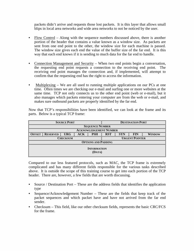
Now that TCP’s responsibilities have been identified, we can look at the frame and itsparts. Below is a typical TCP frame:
SOURCE PORT DESTINATION PORT
SEQUENCE NUMBER
ACKNOWLEDGEMENT NUMBER
OFFSET RESERVED URG ACK PSH RST SYN FIN WINDOW
CHECKSUM URGENT POINTER
OPTIONS AND PADDING
INFORMATION(DATA)
Compared to our less featured protocols, such as MAC, the TCP frame is extremelycomplicated and has many different fields responsible for the various tasks describedabove. It is outside the scope of this training course to get into each portion of the TCPheader. There are, however, a few fields that are worth discussing.
• Source / Destination Port – These are the address fields that identifies the applicationtype
• Sequence/Acknowledgement Number – These are the fields that keep track of thepacket sequences and which packet have and have not arrived from the far endsender.
• Checksum – This field, like our other checksum fields, represents the basic CRC/FCSfor the frame.
2.2.4.2 ETHERNET 101 – UDP – CONNECTIONLESS
UDP is simpler protocol than TCP. UDP is designed with the following features:1. Basic data transfer2. Connection management
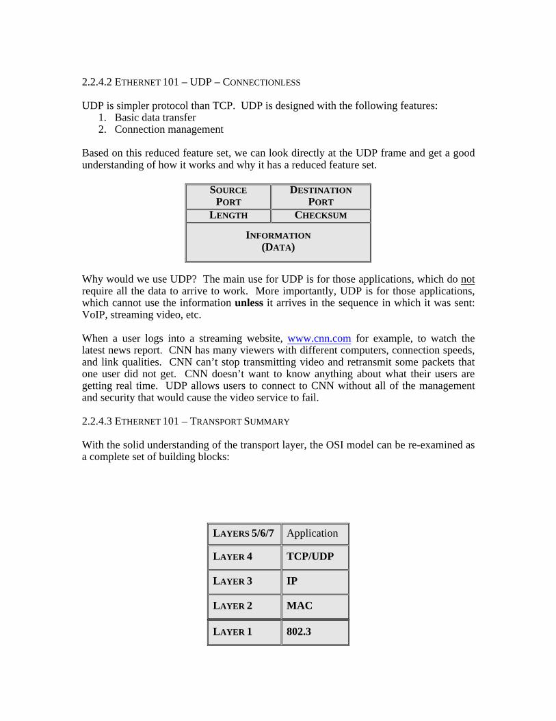
Based on this reduced feature set, we can look directly at the UDP frame and get a goodunderstanding of how it works and why it has a reduced feature set.
SOURCEPORT
DESTINATIONPORT
LENGTH CHECKSUM
INFORMATION(DATA)
Why would we use UDP? The main use for UDP is for those applications, which do notrequire all the data to arrive to work. More importantly, UDP is for those applications,which cannot use the information unless it arrives in the sequence in which it was sent:VoIP, streaming video, etc.
When a user logs into a streaming website, www.cnn.com for example, to watch thelatest news report. CNN has many viewers with different computers, connection speeds,and link qualities. CNN can’t stop transmitting video and retransmit some packets thatone user did not get. CNN doesn’t want to know anything about what their users aregetting real time. UDP allows users to connect to CNN without all of the managementand security that would cause the video service to fail.
2.2.4.3 ETHERNET 101 – TRANSPORT SUMMARY
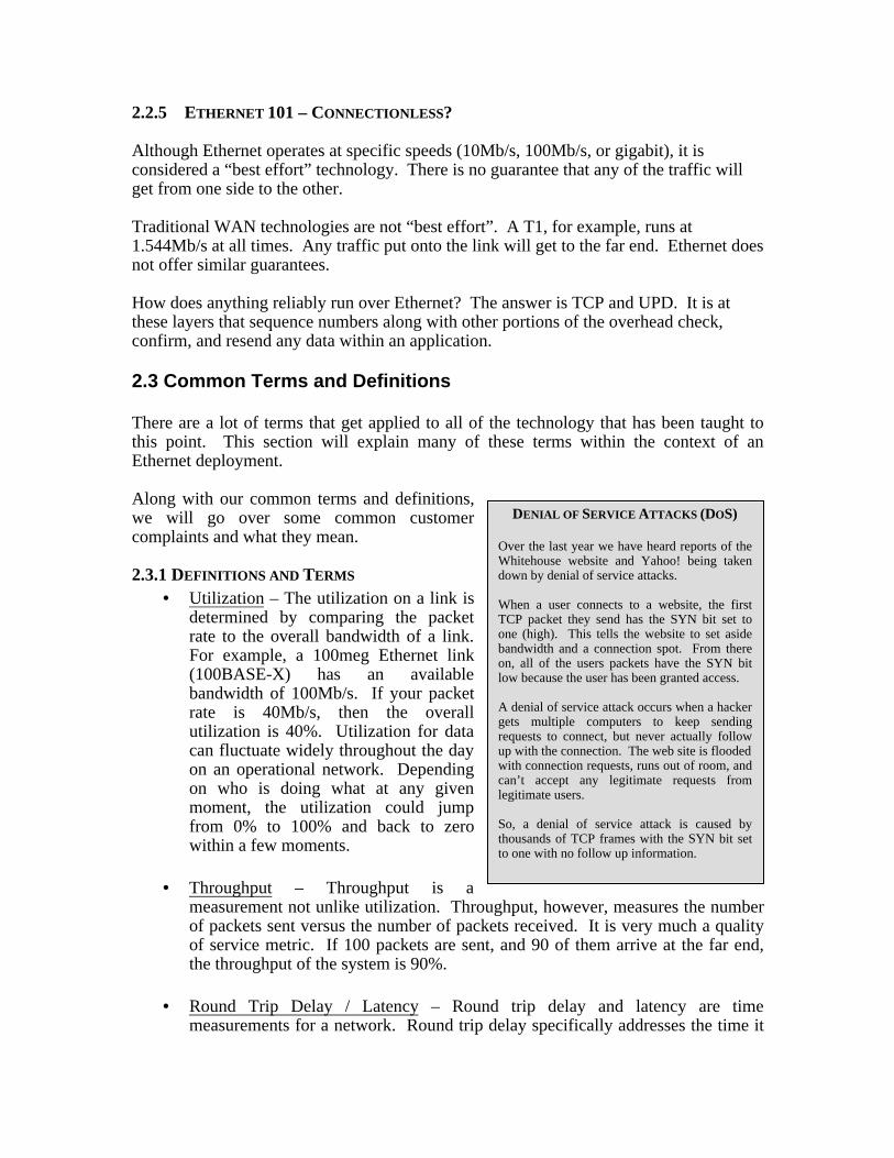
With the solid understanding of the transport layer, the OSI model can be re-examined asa complete set of building blocks:
LAYERS 5/6/7 Application
LAYER 4 TCP/UDP
LAYER 3 IP
LAYER 2 MAC
LAYER 1 802.3
2.2.5 ETHERNET 101 – CONNECTIONLESS?
Although Ethernet operates at specific speeds (10Mb/s, 100Mb/s, or gigabit), it isconsidered a “best effort” technology. There is no guarantee that any of the traffic willget from one side to the other.
Traditional WAN technologies are not “best effort”. A T1, for example, runs at1.544Mb/s at all times. Any traffic put onto the link will get to the far end. Ethernet doesnot offer similar guarantees.
How does anything reliably run over Ethernet? The answer is TCP and UPD. It is atthese layers that sequence numbers along with other portions of the overhead check,confirm, and resend any data within an application.
2.3 Common Terms and Definitions
There are a lot of terms that get applied to all of the technology that has been taught tothis point. This section will explain many of these terms within the context of anEthernet deployment.
Along with our common terms and definitions,we will go over some common customercomplaints and what they mean.
2.3.1 DEFINITIONS AND TERMS
• Utilization – The utilization on a link isdetermined by comparing the packetrate to the overall bandwidth of a link.For example, a 100meg Ethernet link(100BASE-X) has an availablebandwidth of 100Mb/s. If your packetrate is 40Mb/s, then the overallutilization is 40%. Utilization for datacan fluctuate widely throughout the dayon an operational network. Dependingon who is doing what at any givenmoment, the utilization could jumpfrom 0% to 100% and back to zerowithin a few moments.
• Throughput – Throughput is ameasurement not unlike utilization. Throughput, however, measures the numberof packets sent versus the number of packets received. It is very much a qualityof service metric. If 100 packets are sent, and 90 of them arrive at the far end,the throughput of the system is 90%.
• Round Trip Delay / Latency – Round trip delay and latency are timemeasurements for a network. Round trip delay specifically addresses the time it
DENIAL OF SERVICE ATTACKS (DOS)
Over the last year we have heard reports of theWhitehouse website and Yahoo! being takendown by denial of service attacks.
When a user connects to a website, the firstTCP packet they send has the SYN bit set toone (high). This tells the website to set asidebandwidth and a connection spot. From thereon, all of the users packets have the SYN bitlow because the user has been granted access.
A denial of service attack occurs when a hackergets multiple computers to keep sendingrequests to connect, but never actually followup with the connection. The web site is floodedwith connection requests, runs out of room, andcan’t accept any legitimate requests fromlegitimate users.
So, a denial of service attack is caused bythousands of TCP frames with the SYN bit setto one with no follow up information.
takes for a packet to go from one point on the network to another point and backagain. Latency is the time from one point to another. Latency can be measuredfor a single element (router) or for an entire network path.
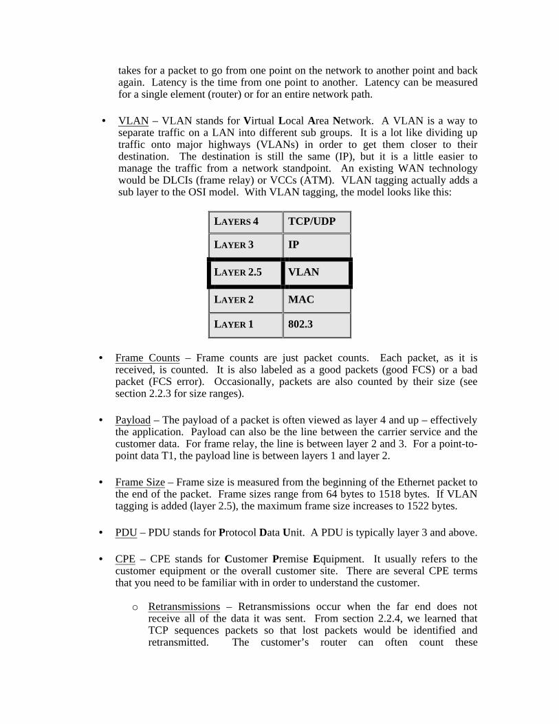
• VLAN – VLAN stands for Virtual Local Area Network. A VLAN is a way toseparate traffic on a LAN into different sub groups. It is a lot like dividing uptraffic onto major highways (VLANs) in order to get them closer to theirdestination. The destination is still the same (IP), but it is a little easier tomanage the traffic from a network standpoint. An existing WAN technologywould be DLCIs (frame relay) or VCCs (ATM). VLAN tagging actually adds asub layer to the OSI model. With VLAN tagging, the model looks like this:
LAYERS 4 TCP/UDP
LAYER 3 IP
LAYER 2.5 VLAN
LAYER 2 MAC
LAYER 1 802.3
• Frame Counts – Frame counts are just packet counts. Each packet, as it isreceived, is counted. It is also labeled as a good packets (good FCS) or a badpacket (FCS error). Occasionally, packets are also counted by their size (seesection 2.2.3 for size ranges).
• Payload – The payload of a packet is often viewed as layer 4 and up – effectivelythe application. Payload can also be the line between the carrier service and thecustomer data. For frame relay, the line is between layer 2 and 3. For a point-to-point data T1, the payload line is between layers 1 and layer 2.
• Frame Size – Frame size is measured from the beginning of the Ethernet packet tothe end of the packet. Frame sizes range from 64 bytes to 1518 bytes. If VLANtagging is added (layer 2.5), the maximum frame size increases to 1522 bytes.
• PDU – PDU stands for Protocol Data Unit. A PDU is typically layer 3 and above.
• CPE – CPE stands for Customer Premise Equipment. It usually refers to thecustomer equipment or the overall customer site. There are several CPE termsthat you need to be familiar with in order to understand the customer.
o Retransmissions – Retransmissions occur when the far end does notreceive all of the data it was sent. From section 2.2.4, we learned thatTCP sequences packets so that lost packets would be identified andretransmitted. The customer’s router can often count these
retransmissions and express them as an error condition. It is important toremember that errors in the lower layers can corrupt the higher layers, soretransmissions can be a sign of a physical layer, data link layer, or eventhe network layer.
o Ping – Another common CPE term is a “ping”. A ping is a packet that issent from a source address to a destination address and back again. Thisallows a user to determine if the network will allow traffic to go from onepoint to another. If a customer can’t “ping” the far end device, he can’tsend traffic there.
o Trace Route – A trace route is a means for a user to trace all IPaddressable devices in the network from one point to another. This allowsthe user to see all the points along the way of a packet’s journey. Ananalogy would be when FedEX scans a package as it goes through eachone of its distribution centers. The user can see each point the packagetouched on its journey.
• Ethernet Errors – There are several types of Ethernet errors that you need to beaware of in order to turn-up and troubleshoot an Ethernet service:
o Runts/Undersize – These errors are generically defined as any packet lessthen the minimum 64 byte length and does not have a CRC/FCS value.
o Jabbers/Oversize – A jabber is the opposite of a runt. These are overlylong packets (> 1518 bytes). Broken NIC cards/ports often cause jabbers
o Bad FCS – Bad FCS frames are those frames with an incorrect CRC/FCSvalue. These are counted when one or more of the bits in a packet havebeen switched (e.g. 1 to a 0).
o Collisions – On a half-duplex Ethernet link, each computer has to sharethe bandwidth with the rest of the computers. If two or more computerson the network broadcast at the same time, the packets “collide” and areunreadable. This event is known as a collision. On full-duplex links, thisis a non-event because there are separate transmit and receive paths.
o Symbol Errors – Symbol errors represent a line coding issues at thephysical layer.
Section 3 – Gigabit / 10BASE-X / 100BASE-X DeploymentMost carriers are offering two versions of the Ethernet services to date. One of theservices is based on the “transparent LAN” model. The other is based on the“addressable LAN” model.
3.1 – Deployment OptionsThe two deployment options, transparent and addressable, are based on the OSI layer thatis required for the traffic to transverse the network.
3.1.1 – TRANSPARENT LAN (OSI LAYER 1 SERVICE)By “transparent” we mean that the LAN sites on either end of the service are tied togetherby a pipe, and have no idea if the Ethernet traffic is traveling 5 feet or 50 miles.Transparent service requires only that the first layer of the OSI model (physical) isproperly formatted in order to pass traffic. If the electrical or optical characteristics of thesignal are correct, the service will pass the data. This service is ONLY point-to-point.
Typically, this type of service is offered via a DWDM (Dense Wave DivisionMultiplexing) system. Instead of a SONET card being the customer interface, the card isEthernet (typically gigabit). Whatever the card receives is transmitted over the long hauland delivered to the far end, converted back to the appropriate wavelength for theEthernet service.
Another way for transparent LANs to work is through media converters. A mediaconvert takes a signal – electrical or optical – and converts it into a long haul opticalsignal. This allows 10BASE-X or 100BASE-X to travel miles. Gigabit Ethernet,although already optical, can benefit from media converters. Normally gigabit Ethernetis available at 850nm or 1310nm – both considered short haul wavelengths. A mediaconverter can receive the 850nm or 1310nm and convert it to 1550nm.
A final option for transparent services is using a standard ADM (Add/Drop Multiplexer).Like the DWDM based option, the Ethernet signal is placed directly into the transportsystem. Unlike the DWDM option, the signal is limited by the SONET signal structure.If the SONET pipe available to the Ethernet is only an STS-12 (622Mb/s), the Ethernet islimited to an OC-12 worth of bandwidth. For 10BASE-X or 100BASE-X, this is morethan enough. For gigabit Ethernet (1.25Gb/s), however, an STS-12 circuit only offersabout 60% of the room required. The customer only has access to 60% of the totalpossible bandwidth. To overcome this, some providers are offering gigabit Ethernetencapsulated into an STS-24c or STS-48c.
3.1.2 ADDRESSABLE LAN (OSI LAYER 2 SERVICE)This type of offering has more flexibility but it is slightly more complicated to turn-upand troubleshoot. In order for this service to operate, the customer must provide sometype of addressing. In OSI terms, this requires the customer to correctly address at layer2, layer 2.5, or layer 3. By using addressing schemes, the carrier can sell the service as apoint-to-multipoint service instead of just a point-to-point.
A layer 2 service (MAC layer) is the most common available today. This type of serviceis typically offered using an OSR (Optical Switched Router). An OSR looks at theEthernet packets and routes them based on their destination MAC address. An incorrectdestination MAC address causes the OSR to ignore the packet. The core network for aMAC based service can be a traditional core, such as ATM.
A layer 2.5 service (VLAN layer) is available with some carriers today and on thehorizon for most. VLAN tagging allows the user to easily set up a point-to-multipointnetwork using a very simple addressing scheme. Also, the tags are very easy for thecarrier to read and allow for quick and efficient routing. The core network for this
service can be traditional ATM, but requires the OSR to map different VLAN tags to theappropriate ATM circuit.
A layer 3 service (IP layer) is not widely deployed today. In order for a full IPaddressable service to be offered, a large IP network would need to be set up in the core,typically a POS (Packet Over SONET) network. Without an IP core, IP addressableLANs will not come to fruition.
Another layer 3 type of service is generically called managed Ethernet. When the wordmanaged is added, the carrier owns that portion of the service. An example of a managedEthernet service would be a VPN. Many enterprise networks currently utilize VPNs, butthe VPN server is owned and operated by the enterprise customer.
3.2 Network ArchitectureFor carriers, these are the different types of equipment and architecture that will be usedto deploy Ethernet. Currently, both point-to-point services as well as point-to-multipointservices are available.
3.2.1 MEDIA CONVERTER DEPLOYMENTThis deployment is based on a transparent service using media converters. Effectively,the carrier takes a signal and converts it to a different type of signal, without corruptedany data.
For the most part, 10BASE-X and 100BASE-X circuit are converted to an optical signalfor long haul transport. Gigabit Ethernet is often converted from 850nm or 1310nm to a1550nm signal.
This signal may remain as native Ethernet over fiber from end-to-end, or it may beencapsulated in a traditional WAN service, such as SONET or ATM, while traversing thecloud. This transformation is totally transparent to the customer.
3.2.2 ROUTER/OSR POINT-TO-MULTI-POINTA router or OSR (Optical Switched Router) type deployment offers carriers moreflexibility and growth than a DWDM point-to-point Ethernet deployment. The serviceuses addressing schemes either at layer 2, layer 2.5, or layer 3.
Because the service requires addressing to route the packets, any turn-up of the servicewill require addressing on the test set. If either the technician or the customer mis-addresses packets, the pipe will not pass any of the traffic, making the circuit look downat the physical layer. The problem, however, is at higher levels.
Section 4 – Turn-up and troubleshooting of Ethernet networksFor the purposes of this section, we will discuss turn-up and troubleshooting of a basicEthernet service. The screen shots shown throughout this document will be using anActerna FST-2802 Ethernet services test tool. Other Acterna products, such as the DA-3400 and the DominoFE and DomnioGIG offer similar feature sets and could be used inplace of the FST-2802.
HOW LONG TO GENERATE TRAFFIC?
The time required to fully test a circuit varieswith the speed of the circuit. Lower speedscircuits, such as a T1, have test lengthrequirements of 15 to 45 minutes (ANSIT1.510). Higher speed circuits require evenlonger test times.
A circuit tested for a short time period (30seconds to just a few minutes) is not trulyproven to be error free. To have any sense thata circuit is going to be reliable, a test should berun for at least 15 full minutes error free.
4.1 Overview of turn-up and troubleshootingAs with any service, turn-up and troubleshooting of Ethernet networks is critical toconfirm that the service works prior to the hand-off. To confirm Ethernet services thetechnician will generate traffic and measure that traffic for various different parameters.This section covers those types of traffic that will need to be generated as well as themeasurements to be made on that traffic.
4.2 Turn-up testing
4.2.1 TRAFFIC GENERATIONAn Ethernet service is a pipe offered to the customer to transport traffic from one point toanother point. In order to confirm that the pipe is clean and will transport the customer’straffic, the technician must generate traffic and confirm that all of the traffic traverses thenetwork without being corrupted.
When setting up a test set to generate traffic, there are three main parameters that must bespecified: utilization, frame size, and traffic profile.
• Utilization – This is the most critical setting. Depending on the service, theEthernet pipe may pass 1.25Gb/s orless. The carrier and type ofnetwork will determine themaximum throughput. Thereforegenerating traffic at the maximumline rate and confirming that thetraffic is not corrupted is critical
• Frame Size – Different frame sizescan affect elements. Smaller framescause elements to work harder thanlarger frames. The reason is thatsmall frames have a smaller payloadand less time for the element toprocess a frame before the nextframe arrives. At high utilizations, the element may drop or corrupt some frames.
• Payload – The payload is the PDU portion of the frame. For the most part, thisportion is irrelevant to the Ethernet service. From a customer standpoint, this isthe most critical portion of the service. Because of this, the ability to edit thepayload may be a requirement for some turn-ups.
4.2.1.1 TRAFFIC RATE – CONSTANT BANDWIDTHWhen setting utilization, there are several different units of measure. The two main unitsof measure are actual bit rate (megabits per second) or percent of the total availablebandwidth. Stating bandwidth in terms of percent of the total available bandwidth is themost common way.
When turning up a circuit, generating traffic at the maximum rate is the only way toconfirm that the circuit can pass the customer data at the guaranteed rate and withouterrors. Depending on how the carrier is offering the Ethernet service, the maximumbandwidth available to the end user may vary.
The maximum bandwidth test should run error free and offer the customer proof that thecircuit will pass traffic appropriately.
4.2.1.2 TRAFFIC RATE – RAMPAnother option for generating traffic is to step up the traffic rate over time. Setting aconstant bandwidth, waiting for a short time, and then restarting the test at a higherbandwidth can accomplish this. The easier way to accomplish this is to have the test setdo it for you.
By stepping up the traffic at specific intervals, the service can be proven to be error freeat all rates, not just at the maximum bandwidth being offered. If there are errors on thelink, the step function will identify the rate at which the errors are being caused.
When setting up a ramp test, there are a couple of extra parameters over the constant ratetest. To begin generating any traffic, the user must enter the step rate (2%, 5%, 10%,etc). Now that you know the step size, the user needs to set the time at each step (20seconds, 1 minute, 5 minutes, etc).
The ramp test, like the constant rate test, confirms that the service works and will pass allof the customer’s traffic without errors.
4.2.1.3 TRAFFIC RATE – BURSTYBursty traffic is a way to simulate real customer data, similar to the QRSS test pattern fora standard T1 BER (Bit Error Rate) test. When the test set is set to bursty, the test setvaries the traffic in two important ways. Firstly, the traffic utilization is adjusted arounda particular rate. If the user sets the average at 50%, the utilization will fluctuate aroundthe 50%, much like customer traffic will.
The frame size (section 2.3.1) is also varied by the test set. Customer traffic has a widevariety of frame sizes due to different applications and their different requirements. Bygenerating the different frames real time, the test set is able to emulate customer datamore easily.
4.2.2 RESULTSAfter setting up and generating traffic, the results of the test need to be analyzed toconfirm that the service will or will not work per the standard.
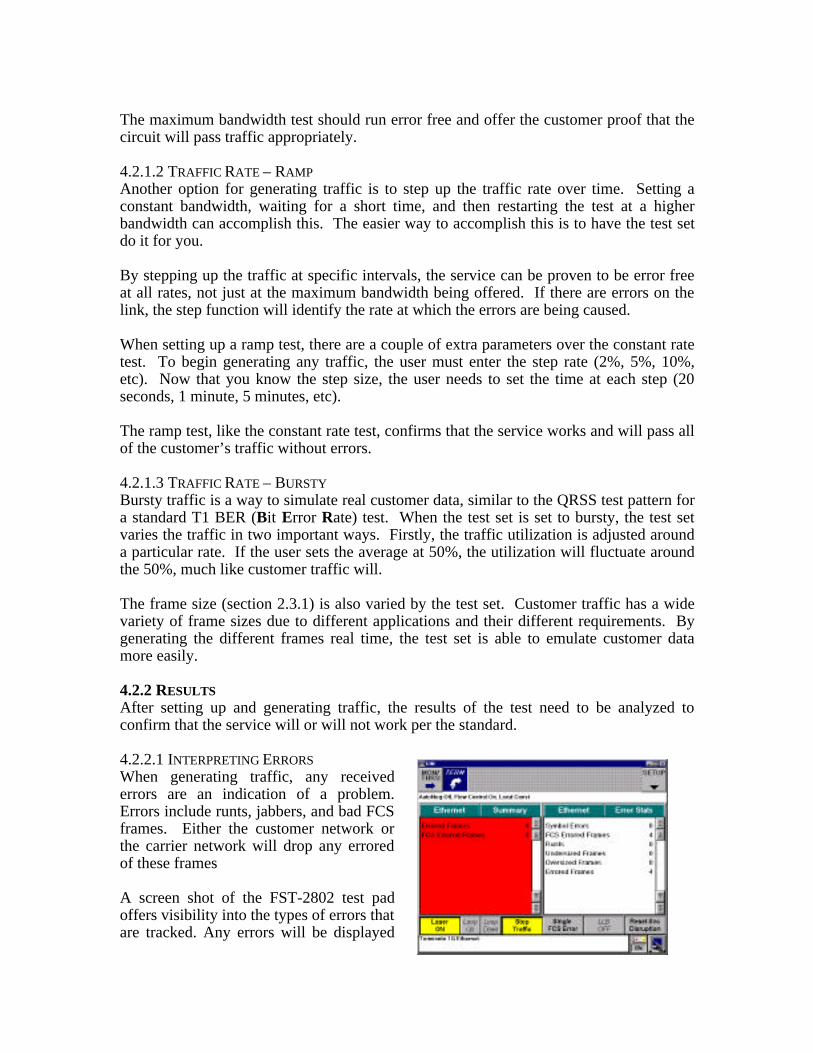
4.2.2.1 INTERPRETING ERRORSWhen generating traffic, any receivederrors are an indication of a problem.Errors include runts, jabbers, and bad FCSframes. Either the customer network orthe carrier network will drop any erroredof these frames
A screen shot of the FST-2802 test padoffers visibility into the types of errors thatare tracked. Any errors will be displayed
for the user to see. Errors will be displayed in two different categories – Error Stats andSummary. The summary view scans all results and picks out anything out ofspecification that is seen by the test unit.
One important error result seen in the summary portion of the picture is the lost framesresult. The FST-2802, as one of its packet generation options, can generate an Acternatest packet. This packet has a sequence number (similar to the TCP sequence number)and a time stamp. This allows the FST-2802 to do real time QoS/SLA analysis includinglost packet rate and round trip delay.
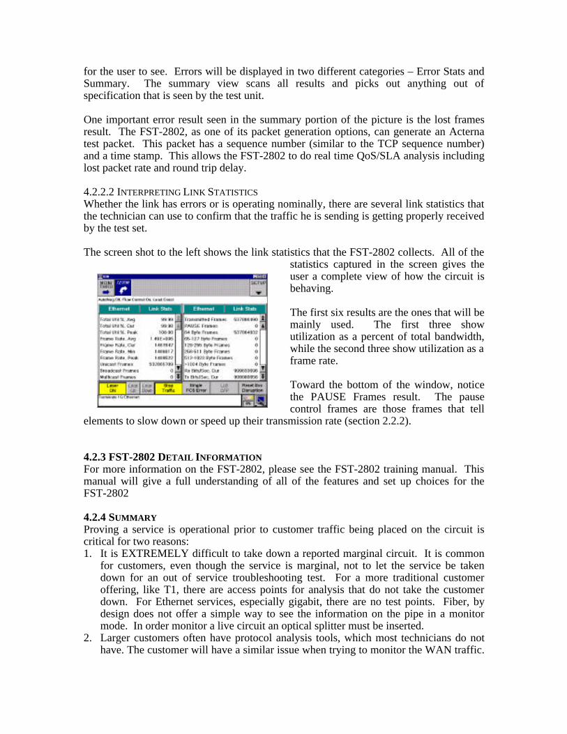
4.2.2.2 INTERPRETING LINK STATISTICSWhether the link has errors or is operating nominally, there are several link statistics thatthe technician can use to confirm that the traffic he is sending is getting properly receivedby the test set.
The screen shot to the left shows the link statistics that the FST-2802 collects. All of thestatistics captured in the screen gives theuser a complete view of how the circuit isbehaving.
The first six results are the ones that will bemainly used. The first three showutilization as a percent of total bandwidth,while the second three show utilization as aframe rate.
Toward the bottom of the window, noticethe PAUSE Frames result. The pausecontrol frames are those frames that tell
elements to slow down or speed up their transmission rate (section 2.2.2).
4.2.3 FST-2802 DETAIL INFORMATIONFor more information on the FST-2802, please see the FST-2802 training manual. Thismanual will give a full understanding of all of the features and set up choices for theFST-2802
4.2.4 SUMMARYProving a service is operational prior to customer traffic being placed on the circuit iscritical for two reasons:1. It is EXTREMELY difficult to take down a reported marginal circuit. It is common
for customers, even though the service is marginal, not to let the service be takendown for an out of service troubleshooting test. For a more traditional customeroffering, like T1, there are access points for analysis that do not take the customerdown. For Ethernet services, especially gigabit, there are no test points. Fiber, bydesign does not offer a simple way to see the information on the pipe in a monitormode. In order monitor a live circuit an optical splitter must be inserted.
2. Larger customers often have protocol analysis tools, which most technicians do nothave. The customer will have a similar issue when trying to monitor the WAN traffic.
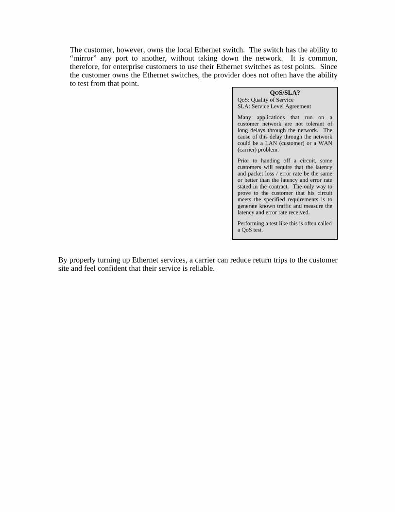
QOS/SLA?QoS: Quality of ServiceSLA: Service Level Agreement
Many applications that run on acustomer network are not tolerant oflong delays through the network. Thecause of this delay through the networkcould be a LAN (customer) or a WAN(carrier) problem.
Prior to handing off a circuit, somecustomers will require that the latencyand packet loss / error rate be the sameor better than the latency and error ratestated in the contract. The only way toprove to the customer that his circuitmeets the specified requirements is togenerate known traffic and measure thelatency and error rate received.
Performing a test like this is often calleda QoS test.
The customer, however, owns the local Ethernet switch. The switch has the ability to“mirror” any port to another, without taking down the network. It is common,therefore, for enterprise customers to use their Ethernet switches as test points. Sincethe customer owns the Ethernet switches, the provider does not often have the abilityto test from that point.
By properly turning up Ethernet services, a carrier can reduce return trips to the customersite and feel confident that their service is reliable.