Embed Size (px)
Citation preview
Ethernet and Vision PLCs 11/09

The information in this document reflects products at the date of printing. Unitronics reserves the right, subject to all applicable laws, at any time, at its sole discretion, and without notice, to discontinue or change the features, designs, materials and other specifications of its products, and to either permanently or temporarily withdraw any of the forgoing from the market.
All information in this document is provided "as is" without warranty of any kind, either expressed or implied, including but not limited to any implied warranties of merchantability, fitness for a particular purpose, or non-infringement. Unitronics assumes no responsibility for errors or omissions in the information presented in this document. In no event shall Unitronics be liable for any special, incidental, indirect or consequential damages of any kind, or any damages whatsoever arising out of or in connection with the use or performance of this information.
The tradenames, trademarks, logos and service marks presented in this document, including their design, are the property of Unitronics (1989) (R"G) Ltd. or other third parties and you are not permitted to use them without the prior written consent of Unitronics or such third party as may own them.

v
Table of Contents Ethernet........................................................................................................ 1
Using Ethernet............................................................................................. 1 General................................................................................................... 1 Default Socket Configuration ..................................................................... 2 MODBUS ................................................................................................. 3
Set PLC Name ........................................................................................... 10 TCP\IP: Card Init ....................................................................................... 10 TCP\IP: Socket Init .................................................................................... 11 TCP\IP: TCP Connect \ TCP Close ................................................................. 12 Ping ......................................................................................................... 13 Send e-mail .............................................................................................. 15
Determining the Protocol Type ................................................................. 15 Determining the IP ................................................................................. 15 Intranet (LAN) mail ................................................................................ 16 How to Configure and Send Messages ....................................................... 16 Configuring the Send e-mail Function........................................................ 17
Ethernet TCP\IP: PC to Vision ...................................................................... 19 TCP/IP Project Settings ........................................................................... 19 TCP/IP Favorites..................................................................................... 21 Vision Communication - PC Settings--Selecting the target PLC ..................... 22
UDP Raw Send/Receive............................................................................... 22 Send..................................................................................................... 22 Scan..................................................................................................... 23
Ethernet: Socket 0, UDP ports ..................................................................... 24 TCP Raw Send/Receive ............................................................................... 24
Send..................................................................................................... 25 Scan..................................................................................................... 25
SNMP ....................................................................................................... 27 Ethernet TCP\IP: SBs & SI .......................................................................... 28 About Ethernet .......................................................................................... 34
About Networks ..................................................................................... 34 What is an IP address?............................................................................ 34 IP Addresses and Networks ..................................................................... 35 Subnet.................................................................................................. 35 Gateway................................................................................................ 36 Socket .................................................................................................. 37 Protocols: UDP and TCP........................................................................... 37 Local Port .............................................................................................. 38 Glossary................................................................................................ 40
Index.......................................................................................................... 43

1
EthernetUsing Ethernet
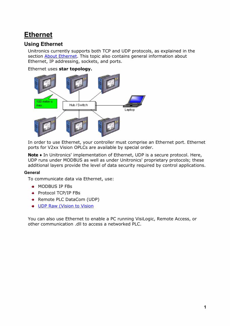
Unitronics currently supports both TCP and UDP protocols, as explained in the section About Ethernet. This topic also contains general information about Ethernet, IP addressing, sockets, and ports.
Ethernet uses star topology.
In order to use Ethernet, your controller must comprise an Ethernet port. Ethernet ports for V2xx Vision OPLCs are available by special order.
Note ♦ In Unitronics' implementation of Ethernet, UDP is a secure protocol. Here, UDP runs under MODBUS as well as under Unitronics' proprietary protocols; these additional layers provide the level of data security required by control applications.
General To communicate data via Ethernet, use:
MODBUS IP FBs
Protocol TCP/IP FBs
Remote PLC DataCom (UDP)
UDP Raw (Vision to Vision
You can also use Ethernet to enable a PC running VisiLogic, Remote Access, or other communication .dll to access a networked PLC.
Unitronics
2
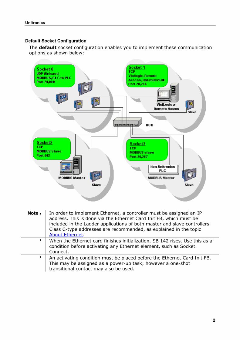
Default Socket Configuration The default socket configuration enables you to implement these communication options as shown below:
Note ♦ In order to implement Ethernet, a controller must be assigned an IP address. This is done via the Ethernet Card Init FB, which must be included in the Ladder applications of both master and slave controllers. Class C-type addresses are recommended, as explained in the topic About Ethernet.
♦ When the Ethernet card finishes initialization, SB 142 rises. Use this as a condition before activating any Ethernet element, such as Socket Connect.
♦ An activating condition must be placed before the Ethernet Card Init FB. This may be assigned as a power-up task; however a one-shot transitional contact may also be used.
Ethernet and Vision PLCs
3
Ethernet Operations
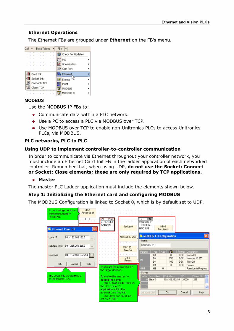
The Ethernet FBs are grouped under Ethernet on the FB's menu.
MODBUS Use the MODBUS IP FBs to:
Communicate data within a PLC network.
Use a PC to access a PLC via MODBUS over TCP.
Use MODBUS over TCP to enable non-Unitronics PLCs to access Unitronics PLCs, via MODBUS.
PLC networks, PLC to PLC
Using UDP to implement controller-to-controller communication
In order to communicate via Ethernet throughout your controller network, you must include an Ethernet Card Init FB in the ladder application of each networked controller. Remember that, when using UDP, do not use the Socket: Connect or Socket: Close elements; these are only required by TCP applications.
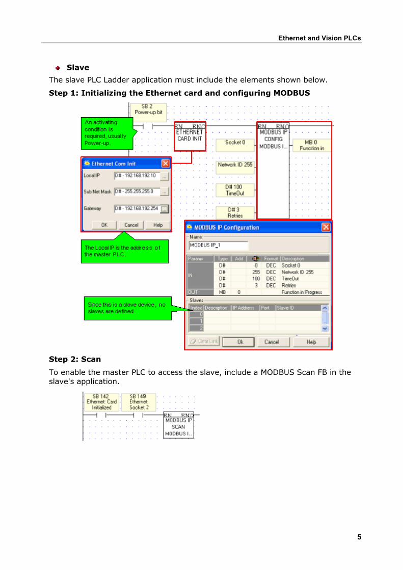
Master
The master PLC Ladder application must include the elements shown below.
Step 1: Initializing the Ethernet card and configuring MODBUS
The MODBUS Configuration is linked to Socket 0, which is by default set to UDP.
Unitronics
4
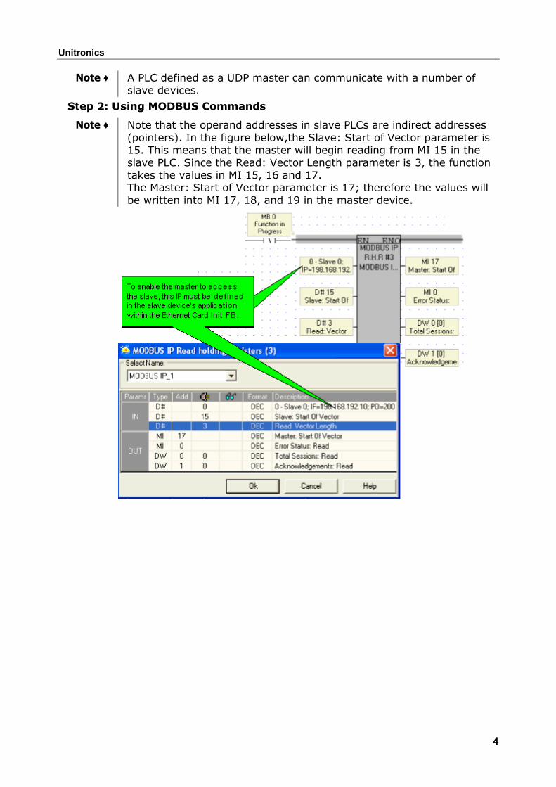
Note ♦ A PLC defined as a UDP master can communicate with a number of slave devices.
Step 2: Using MODBUS Commands
Note ♦ Note that the operand addresses in slave PLCs are indirect addresses (pointers). In the figure below,the Slave: Start of Vector parameter is 15. This means that the master will begin reading from MI 15 in the slave PLC. Since the Read: Vector Length parameter is 3, the function takes the values in MI 15, 16 and 17. The Master: Start of Vector parameter is 17; therefore the values will be written into MI 17, 18, and 19 in the master device.
Ethernet and Vision PLCs
5
Slave
The slave PLC Ladder application must include the elements shown below.
Step 1: Initializing the Ethernet card and configuring MODBUS
Step 2: Scan
To enable the master PLC to access the slave, include a MODBUS Scan FB in the slave's application.
Unitronics
6
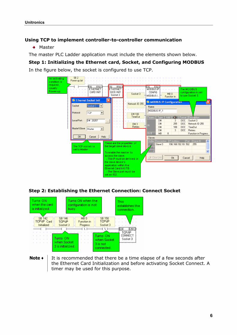
Using TCP to implement controller-to-controller communication
Master
The master PLC Ladder application must include the elements shown below.
Step 1: Initializing the Ethernet card, Socket, and Configuring MODBUS
In the figure below, the socket is configured to use TCP.
Step 2: Establishing the Ethernet Connection: Connect Socket
Note ♦ It is recommended that there be a time elapse of a few seconds after the Ethernet Card Initialization and before activating Socket Connect. A timer may be used for this purpose.
Ethernet and Vision PLCs
7
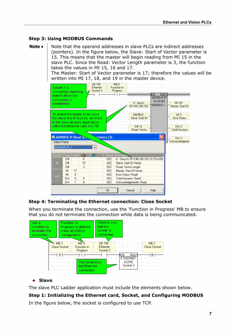
Step 3: Using MODBUS Commands
Note ♦ Note that the operand addresses in slave PLCs are indirect addresses (pointers). In the figure below, the Slave: Start of Vector parameter is 15. This means that the master will begin reading from MI 15 in the slave PLC. Since the Read: Vector Length parameter is 3, the function takes the values in MI 15, 16 and 17. The Master: Start of Vector parameter is 17; therefore the values will be written into MI 17, 18, and 19 in the master device.
Step 4: Terminating the Ethernet connection: Close Socket
When you terminate the connection, use the 'Function in Progress' MB to ensure that you do not terminate the connection while data is being communicated.
Slave
The slave PLC Ladder application must include the elements shown below.
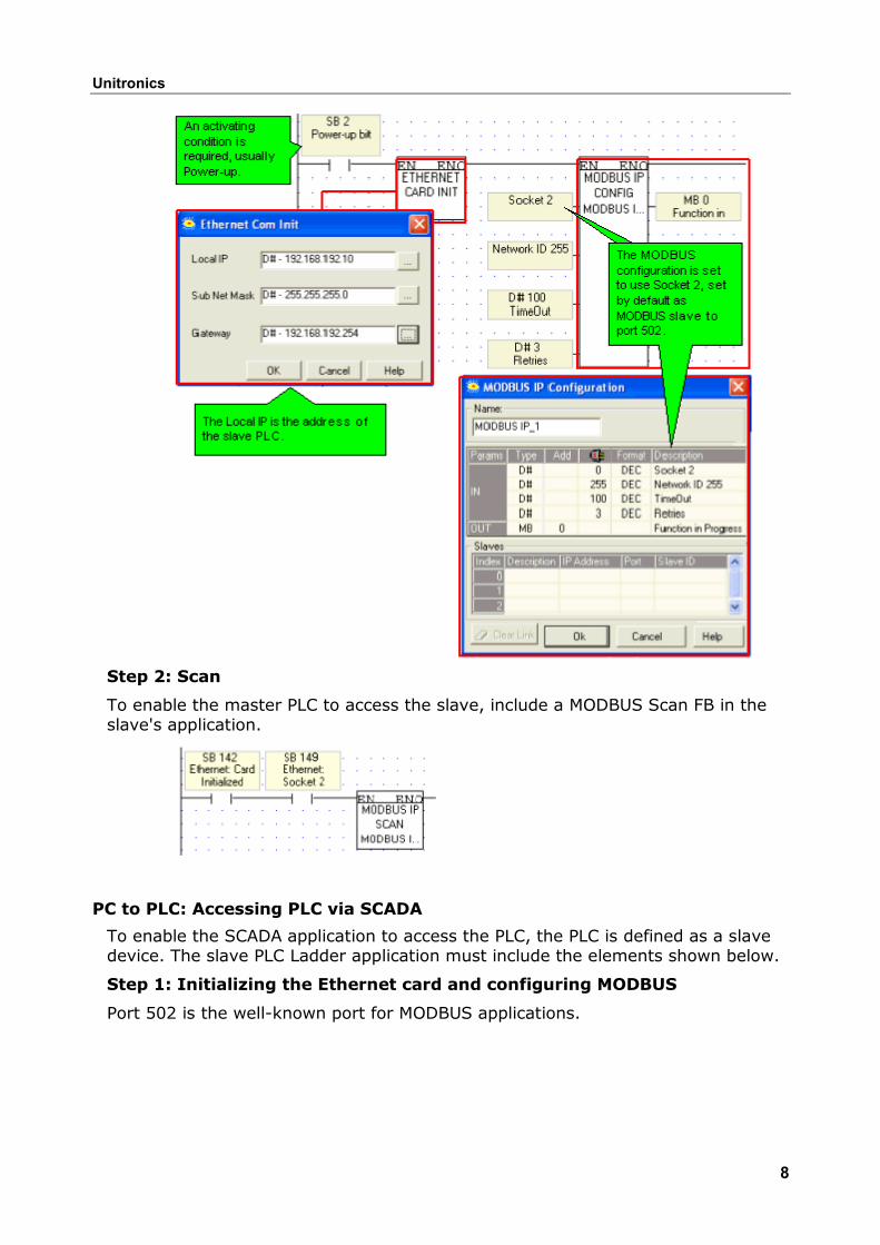
Step 1: Initializing the Ethernet card, Socket, and Configuring MODBUS
In the figure below, the socket is configured to use TCP.
Unitronics
8
Step 2: Scan
To enable the master PLC to access the slave, include a MODBUS Scan FB in the slave's application.
PC to PLC: Accessing PLC via SCADA
To enable the SCADA application to access the PLC, the PLC is defined as a slave device. The slave PLC Ladder application must include the elements shown below.
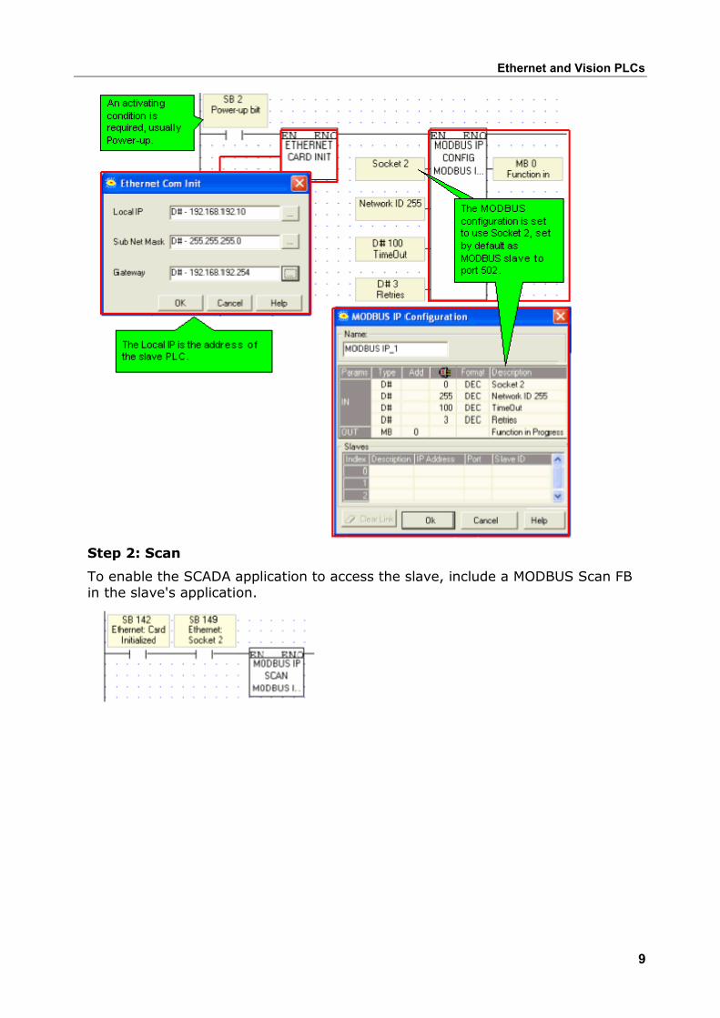
Step 1: Initializing the Ethernet card and configuring MODBUS
Port 502 is the well-known port for MODBUS applications.
Ethernet and Vision PLCs
9
Step 2: Scan
To enable the SCADA application to access the slave, include a MODBUS Scan FB in the slave's application.
Unitronics
10
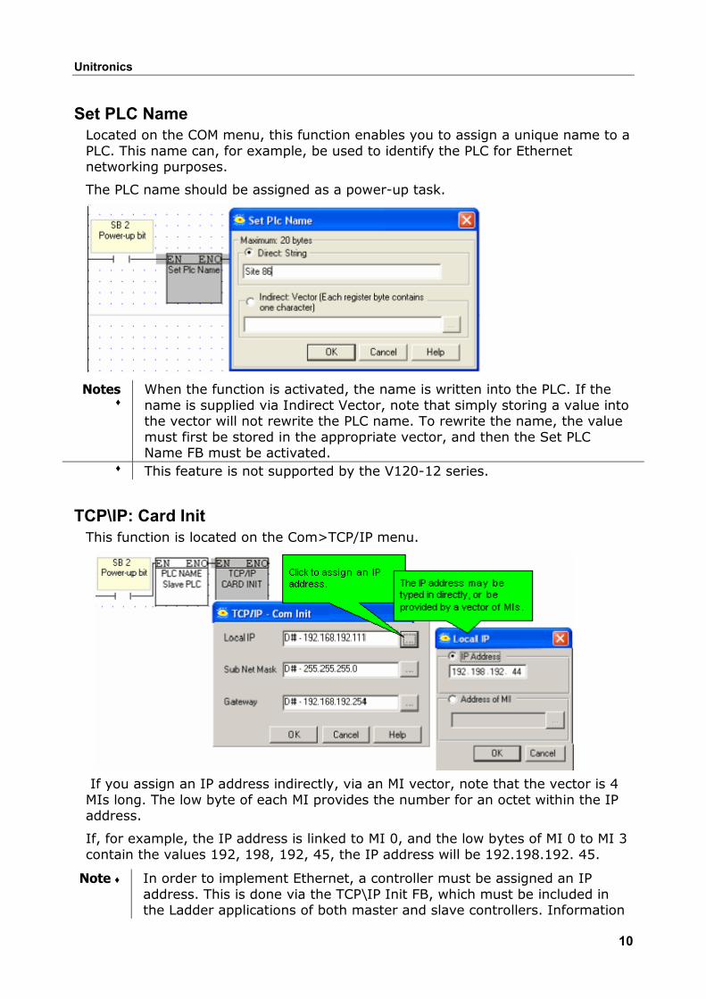
Set PLC Name Located on the COM menu, this function enables you to assign a unique name to a PLC. This name can, for example, be used to identify the PLC for Ethernet networking purposes.
The PLC name should be assigned as a power-up task.
Notes ♦
When the function is activated, the name is written into the PLC. If the name is supplied via Indirect Vector, note that simply storing a value into the vector will not rewrite the PLC name. To rewrite the name, the value must first be stored in the appropriate vector, and then the Set PLC Name FB must be activated.
♦ This feature is not supported by the V120-12 series.
TCP\IP: Card Init This function is located on the Com>TCP/IP menu.
If you assign an IP address indirectly, via an MI vector, note that the vector is 4 MIs long. The low byte of each MI provides the number for an octet within the IP address.
If, for example, the IP address is linked to MI 0, and the low bytes of MI 0 to MI 3 contain the values 192, 198, 192, 45, the IP address will be 192.198.192. 45.
Note ♦ In order to implement Ethernet, a controller must be assigned an IP address. This is done via the TCP\IP Init FB, which must be included in the Ladder applications of both master and slave controllers. Information
Ethernet and Vision PLCs
11
on IP addressing is given in the topic About Ethernet♦ When the Ethernet card finishes initialization, SB 142 rises. Use this as a
condition before activating any Ethernet element, such as Socket: Connect.
♦ An activating condition must be placed before the Ethernet Card Init FB. This may be assigned as a power-up task; however a one-shot transitional contact may also be used.
♦ If you have linked the IP address to a vector of MIs, and this condition is not activated, the IP address will not be assigned to the controller. Make sure, for example, that if you have used a power-up condition, that the controller does go through power-up.
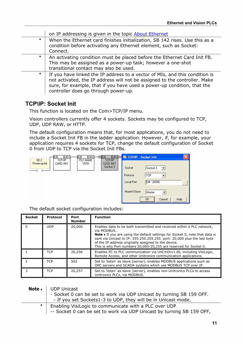
TCP\IP: Socket Init This function is located on the Com>TCP/IP menu.
Vision controllers currently offer 4 sockets. Sockets may be configured to TCP, UDP, UDP RAW, or HTTP.
The default configuration means that, for most applications, you do not need to include a Socket Init FB in the ladder application. However, if, for example, your application requires 4 sockets for TCP, change the default configuration of Socket 0 from UDP to TCP via the Socket Init FBs.
The default socket configuration includes:
Socket Protocol Port Number
Function
0 UDP 20,000 Enables data to be both transmitted and received within a PLC network, via MODBUS. Note ♦ If you are using the default settings for Socket 0, note that data is sent via Unicast to IP: 255.255.255.255. port: 20,000 plus the last byte of the IP address originally assigned to the device. This is why Port numbers 20,000-20,255 are reserved for Socket 0.
1 TCP 20,256 Enables PC to PLC communication via UnCmDrv1.dll, including VisiLogic, Remote Access, and other Unitronics communication applications.
2 TCP 502 Set to 'listen' as slave (server), enables MODBUS applications such as OPC servers and SCADA systems which use MODBUS TCP over IP.
3 TCP 20,257 Set to 'listen' as slave (server), enables non-Unitronics PLCs to access Unitronics PLCs, via MODBUS.
Note ♦ UDP Unicast - Socket 0 can be set to work via UDP Unicast by turning SB 159 OFF. - If you set Sockets1-3 to UDP, they will be in Unicast mode.
♦ Enabling VisiLogic to communicate with a PLC over UDP-- Socket 0 can be set to work via UDP Unicast by turning SB 159 OFF,
Unitronics
12
and then running Socket Init to initialize Socket 0 to UDP. ♦ Select TCP Master to configure a socket to enable the PLC to send e-mail.♦ Select HTTP to configure a socket to enable the PLC to function as a Web
Server.
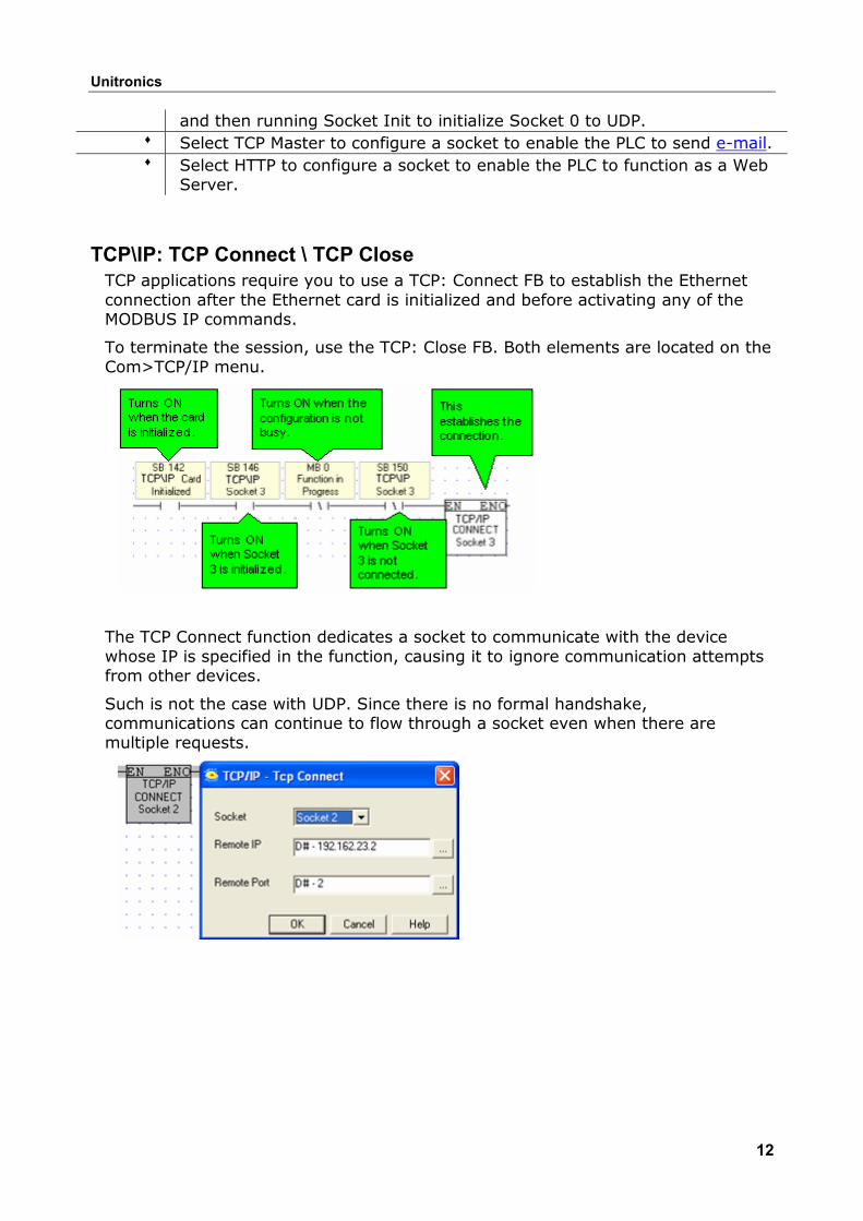
TCP\IP: TCP Connect \ TCP Close TCP applications require you to use a TCP: Connect FB to establish the Ethernet connection after the Ethernet card is initialized and before activating any of the MODBUS IP commands.
To terminate the session, use the TCP: Close FB. Both elements are located on the Com>TCP/IP menu.
The TCP Connect function dedicates a socket to communicate with the device whose IP is specified in the function, causing it to ignore communication attempts from other devices.
Such is not the case with UDP. Since there is no formal handshake, communications can continue to flow through a socket even when there are multiple requests.
Ethernet and Vision PLCs
13
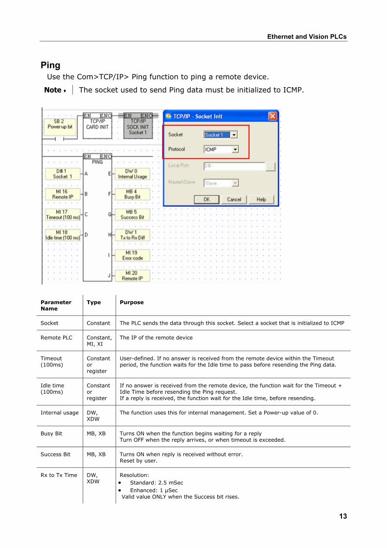
Ping
Use the Com>TCP/IP> Ping function to ping a remote device.
Note ♦ The socket used to send Ping data must be initialized to ICMP.
Parameter Name
Type Purpose
Socket Constant The PLC sends the data through this socket. Select a socket that is initialized to ICMP
Remote PLC Constant, MI, XI
The IP of the remote device
Timeout (100ms)
Constant or register
User-defined. If no answer is received from the remote device within the Timeout period, the function waits for the Idle time to pass before resending the Ping data.
Idle time (100ms)
Constant or register
If no answer is received from the remote device, the function wait for the Timeout + Idle Time before resending the Ping request. If a reply is received, the function wait for the Idle time, before resending.
Internal usage DW, XDW
The function uses this for internal management. Set a Power-up value of 0.
Busy Bit MB, XB Turns ON when the function begins waiting for a reply Turn OFF when the reply arrives, or when timeout is exceeded.
Success Bit MB, XB Turns ON when reply is received without error. Reset by user.
Rx to Tx Time DW, XDW
Resolution: • Standard: 2.5 mSec • Enhanced: 1 µSec Valid value ONLY when the Success bit rises.
Unitronics
14
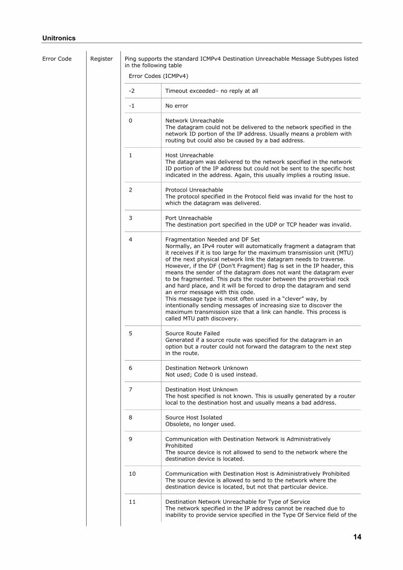
Error Code Register Ping supports the standard ICMPv4 Destination Unreachable Message Subtypes listed in the following table
Error Codes (ICMPv4)
-2 Timeout exceeded– no reply at all
-1 No error
0 Network Unreachable The datagram could not be delivered to the network specified in the network ID portion of the IP address. Usually means a problem with routing but could also be caused by a bad address.
1 Host Unreachable The datagram was delivered to the network specified in the network ID portion of the IP address but could not be sent to the specific host indicated in the address. Again, this usually implies a routing issue.
2 Protocol Unreachable The protocol specified in the Protocol field was invalid for the host to which the datagram was delivered.
3 Port Unreachable The destination port specified in the UDP or TCP header was invalid.
4 Fragmentation Needed and DF Set Normally, an IPv4 router will automatically fragment a datagram that it receives if it is too large for the maximum transmission unit (MTU) of the next physical network link the datagram needs to traverse. However, if the DF (Don't Fragment) flag is set in the IP header, this means the sender of the datagram does not want the datagram ever to be fragmented. This puts the router between the proverbial rock and hard place, and it will be forced to drop the datagram and send an error message with this code. This message type is most often used in a “clever” way, by intentionally sending messages of increasing size to discover the maximum transmission size that a link can handle. This process is called MTU path discovery.
5 Source Route Failed Generated if a source route was specified for the datagram in an option but a router could not forward the datagram to the next step in the route.
6 Destination Network Unknown Not used; Code 0 is used instead.
7 Destination Host Unknown The host specified is not known. This is usually generated by a router local to the destination host and usually means a bad address.
8 Source Host Isolated Obsolete, no longer used.
9 Communication with Destination Network is Administratively Prohibited The source device is not allowed to send to the network where the destination device is located.
10 Communication with Destination Host is Administratively Prohibited The source device is allowed to send to the network where the destination device is located, but not that particular device.
11 Destination Network Unreachable for Type of Service The network specified in the IP address cannot be reached due to inability to provide service specified in the Type Of Service field of the
Ethernet and Vision PLCs
15
datagram header.
12 Destination Host Unreachable for Type of Service The destination host specified in the IP address cannot be reached due to inability to provide service specified in the datagram's Type Of Service field.
13 Communication Administratively Prohibited The datagram could not be forwarded due to filtering that blocks the message based on its contents.
14 Host Precedence Violation Sent by a first-hop router (the first router to handle a sent datagram) when the Precedence value in the Type Of Service field is not permitted.
15 Precedence Cutoff In Effect Sent by a router when receiving a datagram whose Precedence value (priority) is lower than the minimum allowed for the network at that time.
Remote IP The IP from the replying device. Note that it might be different than the “input Remote IP” due to network topology.
Send e-mail This function enables a controller to send an e-mail in response to Ladder conditions. In order to send e-mail, the controller must comprise a TCP/IP port, and must be connected to an Ethernet network with access to a mail server.
Before you begin you need the following information:
The type of protocol your mail server uses, SMTP or ESMTP
Your mail server's IP address
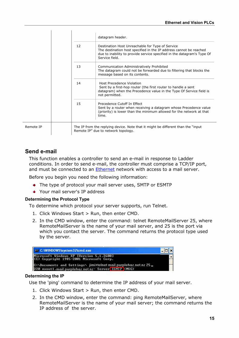
Determining the Protocol Type To determine which protocol your server supports, run Telnet.
1. Click Windows Start > Run, then enter CMD.
2. In the CMD window, enter the command: telnet RemoteMailServer 25, where RemoteMailServer is the name of your mail server, and 25 is the port via which you contact the server. The command returns the protocol type used by the server.
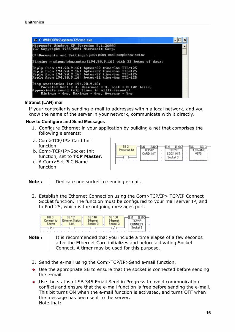
Determining the IP Use the 'ping' command to determine the IP address of your mail server.
1. Click Windows Start > Run, then enter CMD.
2. In the CMD window, enter the command: ping RemoteMailServer, where RemoteMailServer is the name of your mail server; the command returns the IP address of the server.
Unitronics
16
Intranet (LAN) mail If your controller is sending e-mail to addresses within a local network, and you know the name of the server in your network, communicate with it directly.
How to Configure and Send Messages 1. Configure Ethernet in your application by building a net that comprises the
following elements:
a. Com>TCP/IP> Card Init function.
b. Com>TCP/IP>Socket Init function, set to TCP Master.
c. A Com>Set PLC Name function.
Note ♦ Dedicate one socket to sending e-mail.
2. Establish the Ethernet Connection using the Com>TCP/IP> TCP/IP Connect Socket function. The function must be configured to your mail server IP, and to Port 25, which is the outgoing messages port.
Note ♦ It is recommended that you include a time elapse of a few seconds after the Ethernet Card initializes and before activating Socket Connect. A timer may be used for this purpose.
3. Send the e-mail using the Com>TCP/IP>Send e-mail function.
Use the appropriate SB to ensure that the socket is connected before sending the e-mail.
Use the status of SB 345 Email Send in Progress to avoid communication conflicts and ensure that the e-mail function is free before sending the e-mail. This bit turns ON when the e-mail function is activated, and turns OFF when the message has been sent to the server. Note that:
Ethernet and Vision PLCs
17
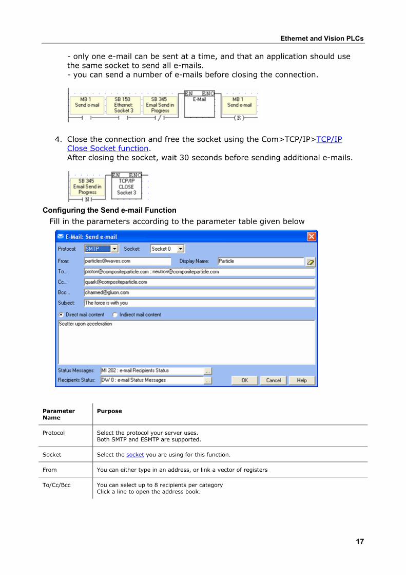
- only one e-mail can be sent at a time, and that an application should use the same socket to send all e-mails. - you can send a number of e-mails before closing the connection.
4. Close the connection and free the socket using the Com>TCP/IP>TCP/IP Close Socket function.After closing the socket, wait 30 seconds before sending additional e-mails.
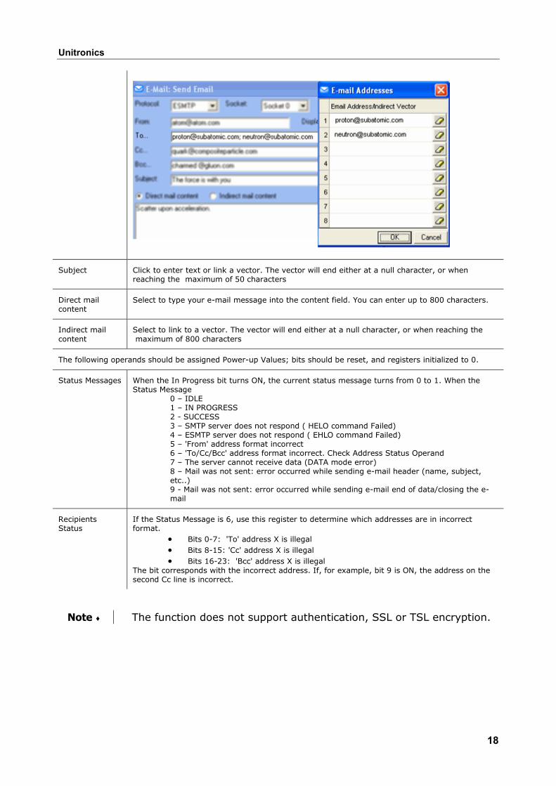
Configuring the Send e-mail Function Fill in the parameters according to the parameter table given below
Parameter Name
Purpose
Protocol Select the protocol your server uses. Both SMTP and ESMTP are supported.
Socket Select the socket you are using for this function.
From You can either type in an address, or link a vector of registers
To/Cc/Bcc You can select up to 8 recipients per category Click a line to open the address book.
Unitronics
18
Subject Click to enter text or link a vector. The vector will end either at a null character, or when reaching the maximum of 50 characters
Direct mail content
Select to type your e-mail message into the content field. You can enter up to 800 characters.
Indirect mail content
Select to link to a vector. The vector will end either at a null character, or when reaching the maximum of 800 characters
The following operands should be assigned Power-up Values; bits should be reset, and registers initialized to 0.
Status Messages When the In Progress bit turns ON, the current status message turns from 0 to 1. When the Status Message
0 – IDLE 1 – IN PROGRESS 2 - SUCCESS 3 – SMTP server does not respond ( HELO command Failed) 4 – ESMTP server does not respond ( EHLO command Failed) 5 – 'From' address format incorrect 6 – 'To/Cc/Bcc' address format incorrect. Check Address Status Operand 7 – The server cannot receive data (DATA mode error) 8 – Mail was not sent: error occurred while sending e-mail header (name, subject, etc..) 9 - Mail was not sent: error occurred while sending e-mail end of data/closing the e-mail
Recipients Status
If the Status Message is 6, use this register to determine which addresses are in incorrect format.
• Bits 0-7: 'To' address X is illegal • Bits 8-15: 'Cc' address X is illegal • Bits 16-23: 'Bcc' address X is illegal
The bit corresponds with the incorrect address. If, for example, bit 9 is ON, the address on the second Cc line is incorrect.
Note ♦ The function does not support authentication, SSL or TSL encryption.
Ethernet and Vision PLCs
19
Ethernet TCP\IP: PC to Vision In order to use a PC to access a Vision controller via Ethernet:
1. The Vision PLC must contain an Ethernet port. Ethernet ports for V2xx Vision OPLCs are available by special order.
2. Both the PC and PLC must be connected to an Ethernet network, and be assigned valid IP addresses; the PLC must be assigned a unique name via the Set PLC Name.
3. The PLC must be defined in either TCP\IP's Ethernet Project Settings or in TCP\IP Favorites .
4. In VisiLogic's Vision Communication - PC Settings: - Ethernet must be selected - the target PLC must be selected from either Favorites or TCP\IP Project Settings.
These conditions enable VisiLogic to access a PLC via Ethernet in order to download programs and carry out other tasks.
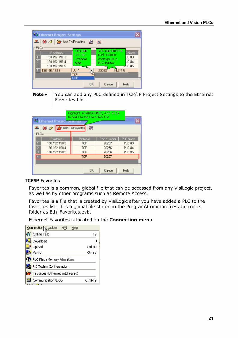
TCP/IP Project Settings TCP/IP Project Settings enable VisiLogic to access a Vision PLC via an Ethernet connection. Each PLC included in the project will be accessed according to the protocol and port number assigned to it.
TCP/IP Project Settings contain IP addresses and settings that are specific to a particular VisiLogic project. However, you can add any of the IP addresses it contains to the Favorites file, which is a common, global file that can be accessed from any VisiLogic project.
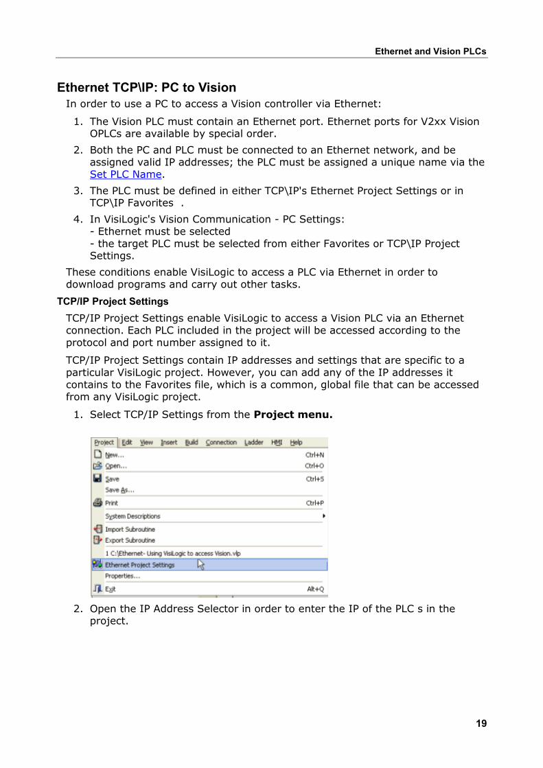
1. Select TCP/IP Settings from the Project menu.
2. Open the IP Address Selector in order to enter the IP of the PLC s in the project.
Unitronics
20
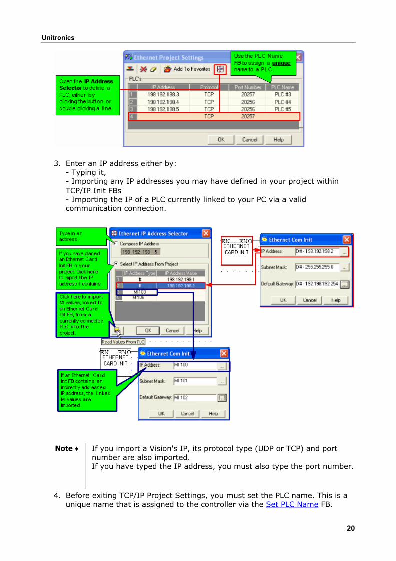
3. Enter an IP address either by: - Typing it, - Importing any IP addresses you may have defined in your project within TCP/IP Init FBs - Importing the IP of a PLC currently linked to your PC via a valid communication connection.
Note ♦ If you import a Vision's IP, its protocol type (UDP or TCP) and port number are also imported. If you have typed the IP address, you must also type the port number.
4. Before exiting TCP/IP Project Settings, you must set the PLC name. This is a unique name that is assigned to the controller via the Set PLC Name FB.
Ethernet and Vision PLCs
21
Note ♦ You can add any PLC defined in TCP/IP Project Settings to the Ethernet Favorites file.
TCP/IP Favorites Favorites is a common, global file that can be accessed from any VisiLogic project, as well as by other programs such as Remote Access.
Favorites is a file that is created by VisiLogic after you have added a PLC to the favorites list. It is a global file stored in the Program\Common files\Unitronics folder as Eth_Favorites.evb.
Ethernet Favorites is located on the Connection menu.
Unitronics
22
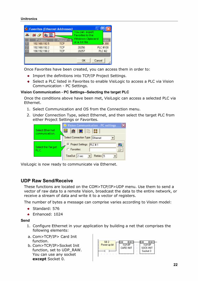
Once Favorites have been created, you can access them in order to:
Import the definitions into TCP/IP Project Settings.
Select a PLC listed in Favorites to enable VisiLogic to access a PLC via Vision Communication - PC Settings.
Vision Communication - PC Settings--Selecting the target PLC Once the conditions above have been met, VisiLogic can access a selected PLC via Ethernet.
1. Select Communication and OS from the Connection menu.
2. Under Connection Type, select Ethernet, and then select the target PLC from either Project Settings or Favorites.
VisiLogic is now ready to communicate via Ethernet.
UDP Raw Send/Receive These functions are located on the COM>TCP/IP>UDP menu. Use them to send a vector of raw data to a remote Vision, broadcast the data to the entire network, or receive a stream of data and write it to a vector of registers.
The number of bytes a message can comprise varies according to Vision model:
Standard: 576
Enhanced: 1024
Send 1. Configure Ethernet in your application by building a net that comprises the
following elements:
a. Com>TCP/IP> Card Init function.
b. Com>TCP/IP>Socket Init function, set to UDP_RAW. You can use any socket except Socket 0.
Ethernet and Vision PLCs
23
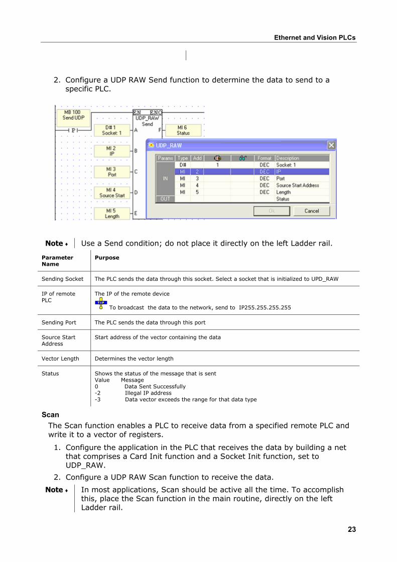
2. Configure a UDP RAW Send function to determine the data to send to a specific PLC.
Note ♦ Use a Send condition; do not place it directly on the left Ladder rail.
Parameter Name
Purpose
Sending Socket The PLC sends the data through this socket. Select a socket that is initialized to UPD_RAW
IP of remote PLC
The IP of the remote device
To broadcast the data to the network, send to IP255.255.255.255
Sending Port The PLC sends the data through this port
Source Start Address
Start address of the vector containing the data
Vector Length Determines the vector length
Status Shows the status of the message that is sent Value Message 0 Data Sent Successfully -2 Illegal IP address -3 Data vector exceeds the range for that data type
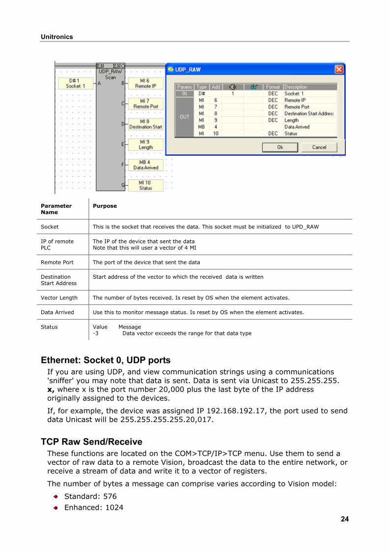
Scan The Scan function enables a PLC to receive data from a specified remote PLC and write it to a vector of registers.
1. Configure the application in the PLC that receives the data by building a net that comprises a Card Init function and a Socket Init function, set to UDP_RAW.
2. Configure a UDP RAW Scan function to receive the data.
Note ♦ In most applications, Scan should be active all the time. To accomplish this, place the Scan function in the main routine, directly on the left Ladder rail.
Unitronics
24
Parameter Name
Purpose
Socket This is the socket that receives the data. This socket must be initialized to UPD_RAW
IP of remote PLC
The IP of the device that sent the data Note that this will user a vector of 4 MI
Remote Port The port of the device that sent the data
Destination Start Address
Start address of the vector to which the received data is written
Vector Length The number of bytes received. Is reset by OS when the element activates.
Data Arrived Use this to monitor message status. Is reset by OS when the element activates.
Status
Value Message -3 Data vector exceeds the range for that data type
Ethernet: Socket 0, UDP ports If you are using UDP, and view communication strings using a communications 'sniffer' you may note that data is sent. Data is sent via Unicast to 255.255.255. x, where x is the port number 20,000 plus the last byte of the IP address originally assigned to the devices.
If, for example, the device was assigned IP 192.168.192.17, the port used to send data Unicast will be 255.255.255.255.20,017.
TCP Raw Send/Receive
These functions are located on the COM>TCP/IP>TCP menu. Use them to send a vector of raw data to a remote Vision, broadcast the data to the entire network, or receive a stream of data and write it to a vector of registers.
The number of bytes a message can comprise varies according to Vision model:
Standard: 576
Enhanced: 1024
Ethernet and Vision PLCs
25
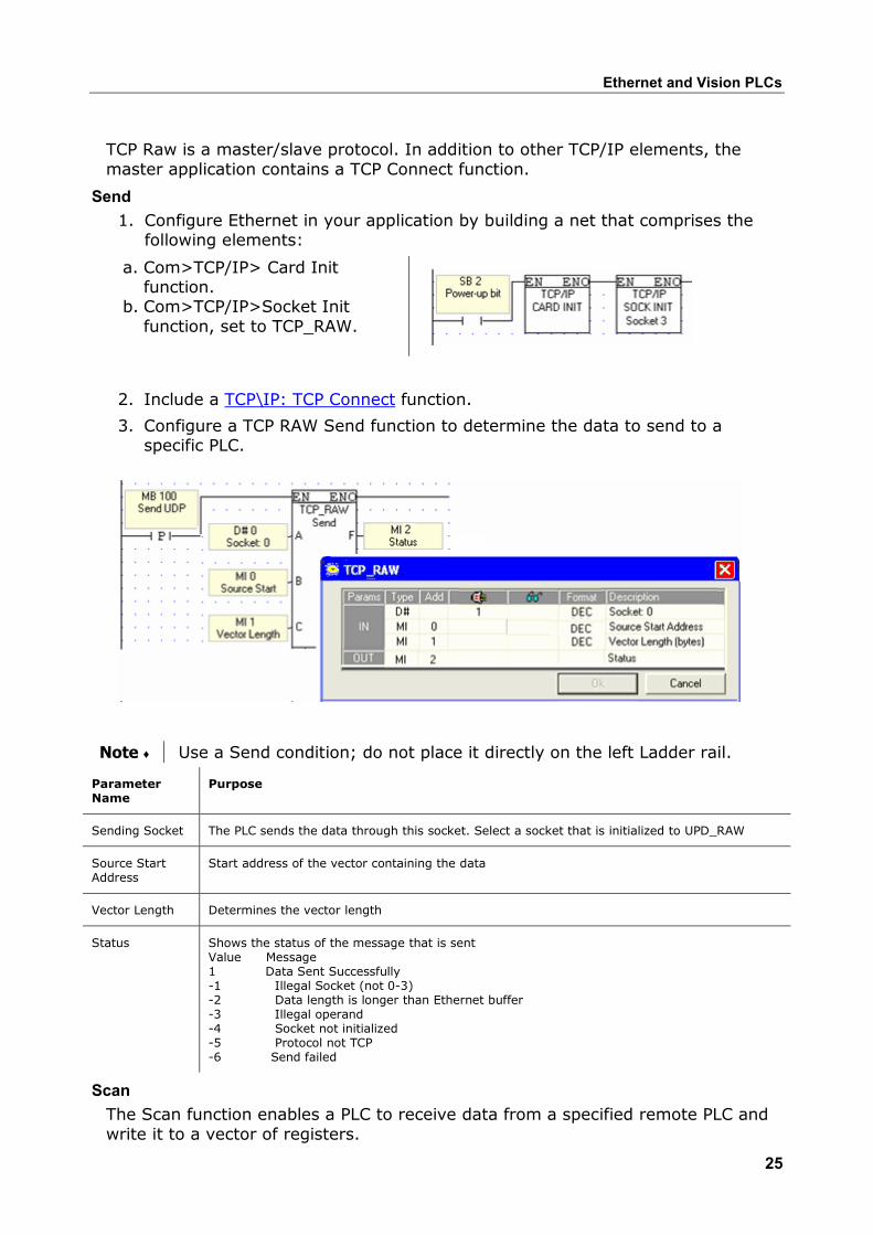
TCP Raw is a master/slave protocol. In addition to other TCP/IP elements, the master application contains a TCP Connect function.
Send 1. Configure Ethernet in your application by building a net that comprises the
following elements:
a. Com>TCP/IP> Card Init function.
b. Com>TCP/IP>Socket Init function, set to TCP_RAW.
2. Include a TCP\IP: TCP Connect function.
3. Configure a TCP RAW Send function to determine the data to send to a specific PLC.
Note ♦ Use a Send condition; do not place it directly on the left Ladder rail.
Parameter Name
Purpose
Sending Socket The PLC sends the data through this socket. Select a socket that is initialized to UPD_RAW
Source Start Address
Start address of the vector containing the data
Vector Length Determines the vector length
Status Shows the status of the message that is sent Value Message 1 Data Sent Successfully -1 Illegal Socket (not 0-3) -2 Data length is longer than Ethernet buffer -3 Illegal operand -4 Socket not initialized -5 Protocol not TCP -6 Send failed
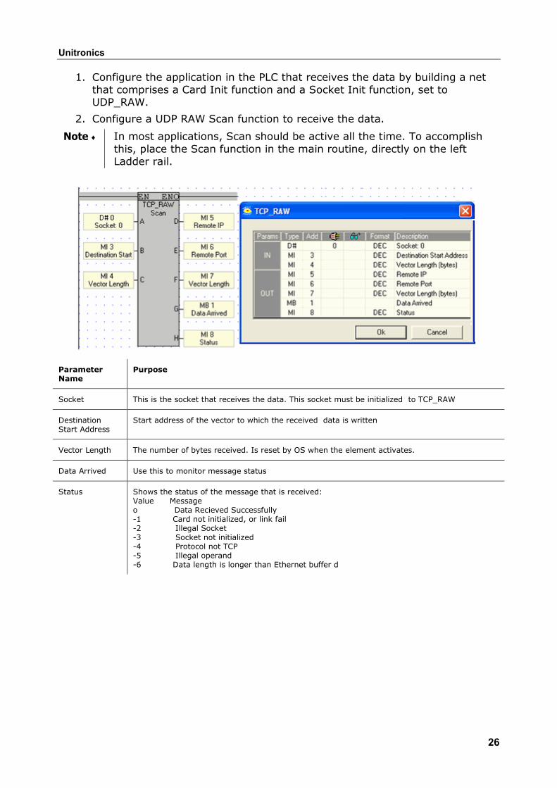
Scan The Scan function enables a PLC to receive data from a specified remote PLC and write it to a vector of registers.
Unitronics
26
1. Configure the application in the PLC that receives the data by building a net that comprises a Card Init function and a Socket Init function, set to UDP_RAW.
2. Configure a UDP RAW Scan function to receive the data.
Note ♦ In most applications, Scan should be active all the time. To accomplish this, place the Scan function in the main routine, directly on the left Ladder rail.
Parameter Name
Purpose
Socket This is the socket that receives the data. This socket must be initialized to TCP_RAW
Destination Start Address
Start address of the vector to which the received data is written
Vector Length The number of bytes received. Is reset by OS when the element activates.
Data Arrived Use this to monitor message status
Status
Shows the status of the message that is received: Value Message o Data Recieved Successfully -1 Card not initialized, or link fail -2 Illegal Socket -3 Socket not initialized -4 Protocol not TCP -5 Illegal operand -6 Data length is longer than Ethernet buffer d
Ethernet and Vision PLCs
27
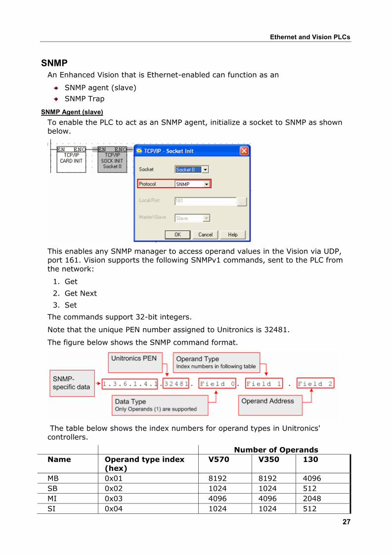
SNMP An Enhanced Vision that is Ethernet-enabled can function as an
SNMP agent (slave)
SNMP Trap
SNMP Agent (slave)To enable the PLC to act as an SNMP agent, initialize a socket to SNMP as shown below.
This enables any SNMP manager to access operand values in the Vision via UDP, port 161. Vision supports the following SNMPv1 commands, sent to the PLC from the network:
1. Get
2. Get Next
3. Set
The commands support 32-bit integers.
Note that the unique PEN number assigned to Unitronics is 32481.
The figure below shows the SNMP command format.
The table below shows the index numbers for operand types in Unitronics' controllers.
Number of Operands Name Operand type index
(hex) V570 V350 130
MB 0x01 8192 8192 4096 SB 0x02 1024 1024 512 MI 0x03 4096 4096 2048 SI 0x04 1024 1024 512
Unitronics
28
ML 0x05 512 512 256 SL 0x06 64 64 56 MF 0x07 64 64 24 MDW 0x10 256 256 64 SDW 0x24 64 64 64 XB 0x40 1024 1024 1024 XI 0x41 512 512 512 XL 0x42 256 256 256 XDW 0x43 64 64 64
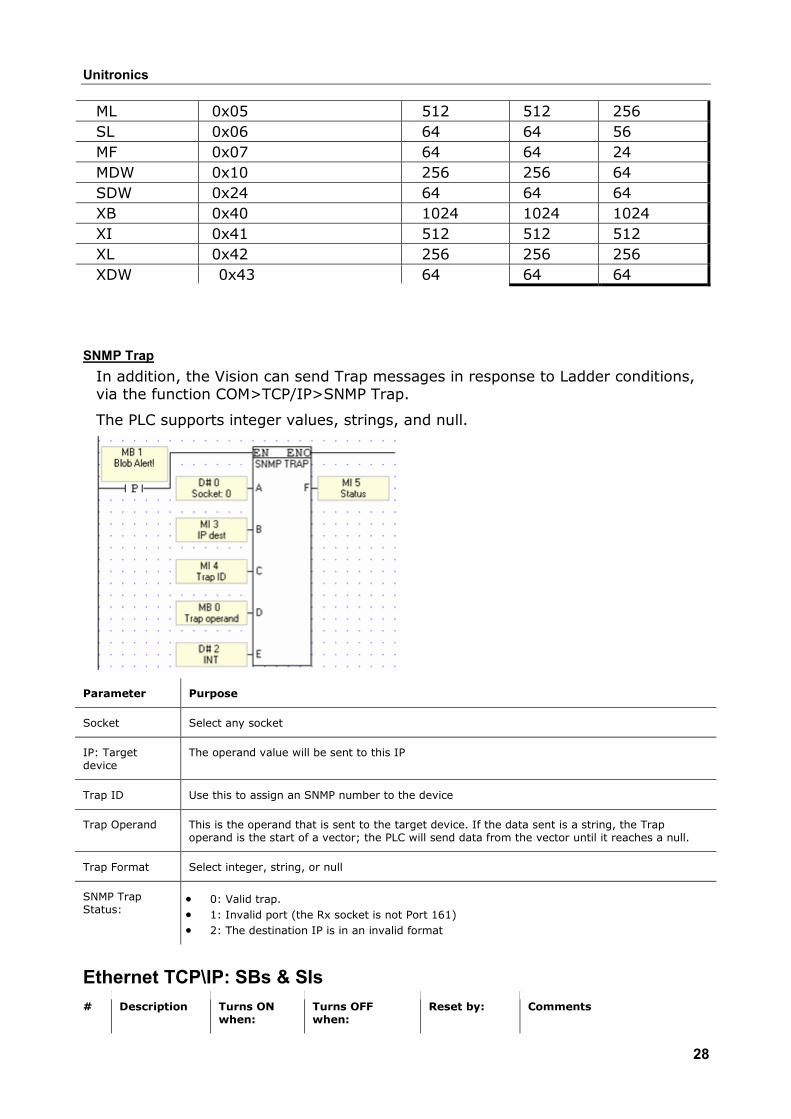
SNMP TrapIn addition, the Vision can send Trap messages in response to Ladder conditions, via the function COM>TCP/IP>SNMP Trap.
The PLC supports integer values, strings, and null.
Parameter Purpose
Socket Select any socket
IP: Target device
The operand value will be sent to this IP
Trap ID Use this to assign an SNMP number to the device
Trap Operand This is the operand that is sent to the target device. If the data sent is a string, the Trap operand is the start of a vector; the PLC will send data from the vector until it reaches a null.
Trap Format Select integer, string, or null
SNMP Trap Status:
• 0: Valid trap. • 1: Invalid port (the Rx socket is not Port 161) • 2: The destination IP is in an invalid format
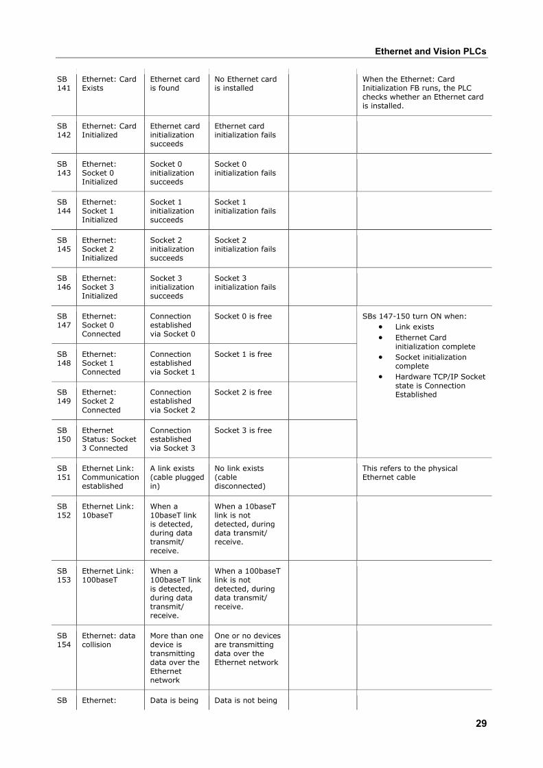
Ethernet TCP\IP: SBs & SIs # Description Turns ON
when: Turns OFF when:
Reset by: Comments
Ethernet and Vision PLCs
29
SB 141
Ethernet: Card Exists
Ethernet card is found
No Ethernet card is installed
When the Ethernet: Card Initialization FB runs, the PLC checks whether an Ethernet card is installed.
SB 142
Ethernet: Card Initialized
Ethernet card initialization succeeds
Ethernet card initialization fails
SB 143
Ethernet: Socket 0 Initialized
Socket 0 initialization succeeds
Socket 0 initialization fails
SB 144
Ethernet: Socket 1 Initialized
Socket 1 initialization succeeds
Socket 1 initialization fails
SB 145
Ethernet: Socket 2 Initialized
Socket 2 initialization succeeds
Socket 2 initialization fails
SB 146
Ethernet: Socket 3 Initialized
Socket 3 initialization succeeds
Socket 3 initialization fails
SB 147
Ethernet: Socket 0 Connected
Connection established via Socket 0
Socket 0 is free
SB 148
Ethernet: Socket 1 Connected
Connection established via Socket 1
Socket 1 is free
SB 149
Ethernet: Socket 2 Connected
Connection established via Socket 2
Socket 2 is free
SB 150
Ethernet Status: Socket 3 Connected
Connection established via Socket 3
Socket 3 is free
SBs 147-150 turn ON when: • Link exists • Ethernet Card
initialization complete • Socket initialization
complete • Hardware TCP/IP Socket
state is Connection Established
SB 151
Ethernet Link: Communication established
A link exists (cable plugged in)
No link exists (cable disconnected)
This refers to the physical Ethernet cable
SB 152
Ethernet Link: 10baseT
When a 10baseT link is detected, during data transmit/ receive.
When a 10baseT link is not detected, during data transmit/ receive.
SB 153
Ethernet Link: 100baseT
When a 100baseT link is detected, during data transmit/ receive.
When a 100baseT link is not detected, during data transmit/ receive.
SB 154
Ethernet: data collision
More than one device is transmitting data over the Ethernet network
One or no devices are transmitting data over the Ethernet network
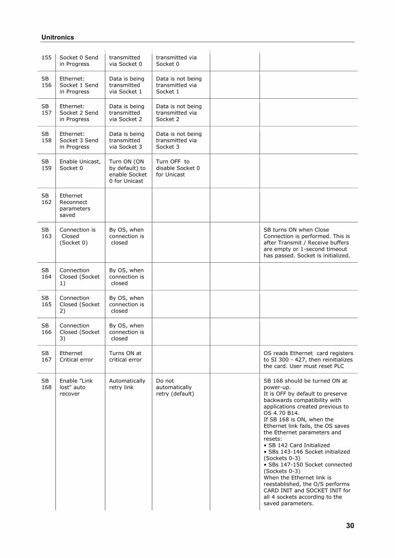
SB Ethernet: Data is being Data is not being
Unitronics
30
155 Socket 0 Send in Progress
transmitted via Socket 0
transmitted via Socket 0
SB 156
Ethernet: Socket 1 Send in Progress
Data is being transmitted via Socket 1
Data is not being transmitted via Socket 1
SB 157
Ethernet: Socket 2 Send in Progress
Data is being transmitted via Socket 2
Data is not being transmitted via Socket 2
SB 158
Ethernet: Socket 3 Send in Progress
Data is being transmitted via Socket 3
Data is not being transmitted via Socket 3
SB 159
Enable Unicast, Socket 0
Turn ON (ON by default) to enable Socket 0 for Unicast
Turn OFF to disable Socket 0 for Unicast
SB 162
Ethernet Reconnect parameters saved
SB 163
Connection is Closed
(Socket 0)
By OS, when connection is closed
SB turns ON when Close Connection is performed. This is after Transmit / Receive buffers are empty or 1-second timeout has passed. Socket is initialized.
SB 164
Connection Closed (Socket 1)
By OS, when connection is closed
SB 165
Connection Closed (Socket 2)
By OS, when connection is closed
SB 166
Connection Closed (Socket 3)
By OS, when connection is closed
SB 167
Ethernet Critical error
Turns ON at critical error
OS reads Ethernet card registers to SI 300 - 427, then reinitializes the card. User must reset PLC
SB 168
Enable "Link lost" auto recover
Automatically retry link
Do not automatically retry (default)
SB 168 should be turned ON at power-up. It is OFF by default to preserve backwards compatibility with applications created previous to OS 4.70 B14. If SB 168 is ON, when the Ethernet link fails, the OS saves the Ethernet parameters and resets: • SB 142 Card Initialized • SBs 143-146 Socket initialized (Sockets 0-3) • SBs 147-150 Socket connected (Sockets 0-3) When the Ethernet link is reestablished, the O/S performs CARD INIT and SOCKET INIT for all 4 sockets according to the saved parameters.
Ethernet and Vision PLCs
31
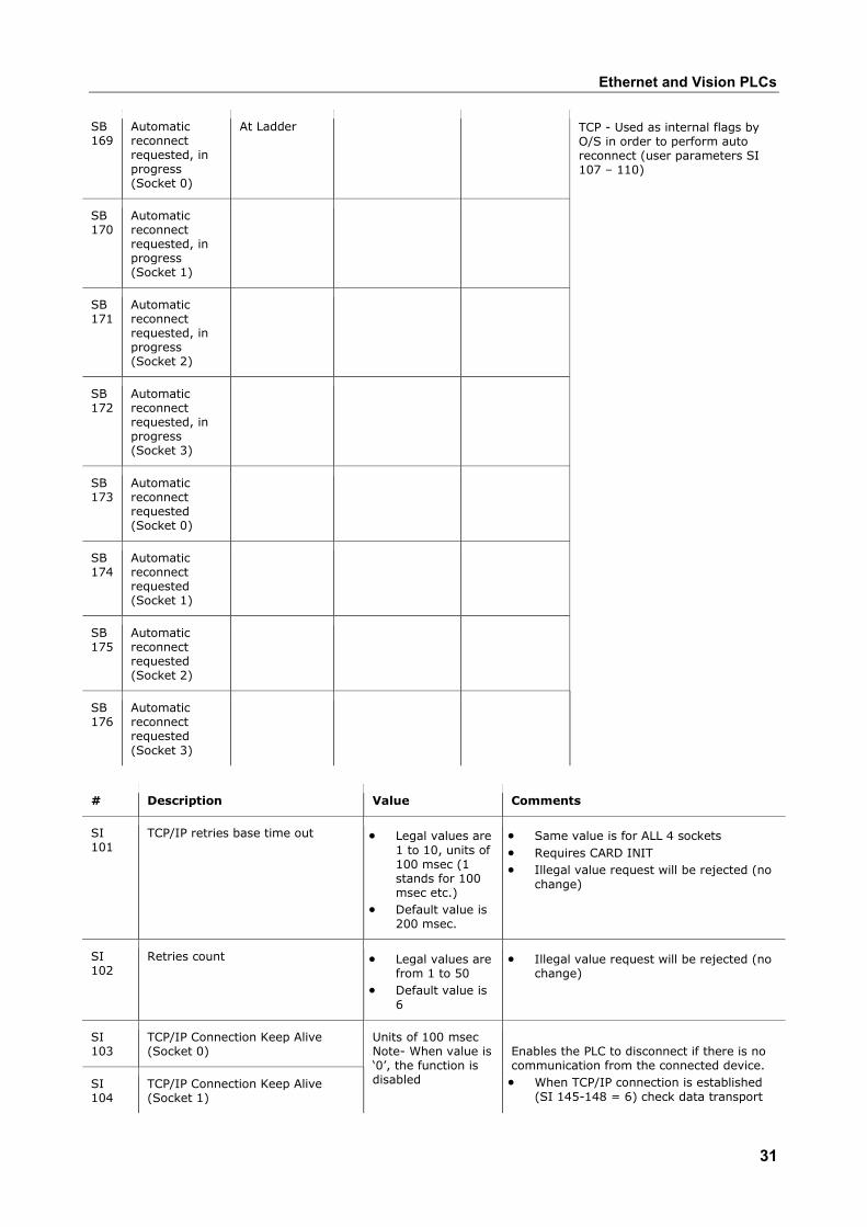
SB 169
Automatic reconnect requested, in progress (Socket 0)
At Ladder
SB 170
Automatic reconnect requested, in progress (Socket 1)
SB 171
Automatic reconnect requested, in progress (Socket 2)
SB 172
Automatic reconnect requested, in progress (Socket 3)
SB 173
Automatic reconnect requested (Socket 0)
SB 174
Automatic reconnect requested (Socket 1)
SB 175
Automatic reconnect requested (Socket 2)
SB 176
Automatic reconnect requested (Socket 3)
TCP - Used as internal flags by O/S in order to perform auto reconnect (user parameters SI 107 – 110)
# Description Value Comments
SI 101
TCP/IP retries base time out • Legal values are 1 to 10, units of 100 msec (1 stands for 100 msec etc.)
• Default value is 200 msec.
• Same value is for ALL 4 sockets • Requires CARD INIT • Illegal value request will be rejected (no
change)
SI 102
Retries count • Legal values are from 1 to 50
• Default value is 6
• Illegal value request will be rejected (no change)
SI 103
TCP/IP Connection Keep Alive (Socket 0)
SI 104
TCP/IP Connection Keep Alive (Socket 1)
Units of 100 msec Note- When value is ‘0’, the function is disabled
Enables the PLC to disconnect if there is no communication from the connected device. • When TCP/IP connection is established
(SI 145-148 = 6) check data transport
Unitronics
32
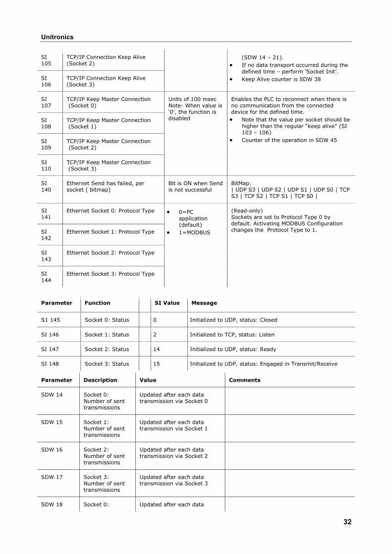
SI 105
TCP/IP Connection Keep Alive (Socket 2)
SI 106
TCP/IP Connection Keep Alive (Socket 3)
(SDW 14 – 21). • If no data transport occurred during the
defined time – perform ‘Socket Init’. • Keep Alive counter is SDW 38
SI 107
TCP/IP Keep Master Connection (Socket 0)
SI 108
TCP/IP Keep Master Connection (Socket 1)
SI 109
TCP/IP Keep Master Connection (Socket 2)
SI 110
TCP/IP Keep Master Connection (Socket 3)
Units of 100 msec Note- When value is ‘0’, the function is disabled
Enables the PLC to reconnect when there is no communication from the connected device for the defined time. • Note that the value per socket should be
higher than the regular “keep alive” (SI 103 – 106)
• Counter of the operation in SDW 45
SI 140
Ethernet Send has failed, per socket ( bitmap)
Bit is ON when Send is not successful
BitMap: | UDP S3 | UDP S2 | UDP S1 | UDP S0 | TCP S3 | TCP S2 | TCP S1 | TCP S0 |
SI 141
Ethernet Socket 0: Protocol Type
SI 142
Ethernet Socket 1: Protocol Type
SI 143
Ethernet Socket 2: Protocol Type
SI 144
Ethernet Socket 3: Protocol Type
• 0=PC application (default)
• 1=MODBUS
(Read-only) Sockets are set to Protocol Type 0 by default. Activating MODBUS Configuration changes the Protocol Type to 1.
Parameter Function SI Value Message
S1 145 Socket 0: Status 0 Initialized to UDP, status: Closed
SI 146 Socket 1: Status 2 Initialized to TCP, status: Listen
SI 147 Socket 2: Status 14 Initialized to UDP, status: Ready
SI 148 Socket 3: Status 15 Initialized to UDP, status: Engaged in Transmit/Receive
Parameter Description Value Comments
SDW 14 Socket 0: Number of sent transmissions
Updated after each data transmission via Socket 0
SDW 15 Socket 1: Number of sent transmissions
Updated after each data transmission via Socket 1
SDW 16 Socket 2: Number of sent transmissions
Updated after each data transmission via Socket 2
SDW 17 Socket 3: Number of sent transmissions
Updated after each data transmission via Socket 3
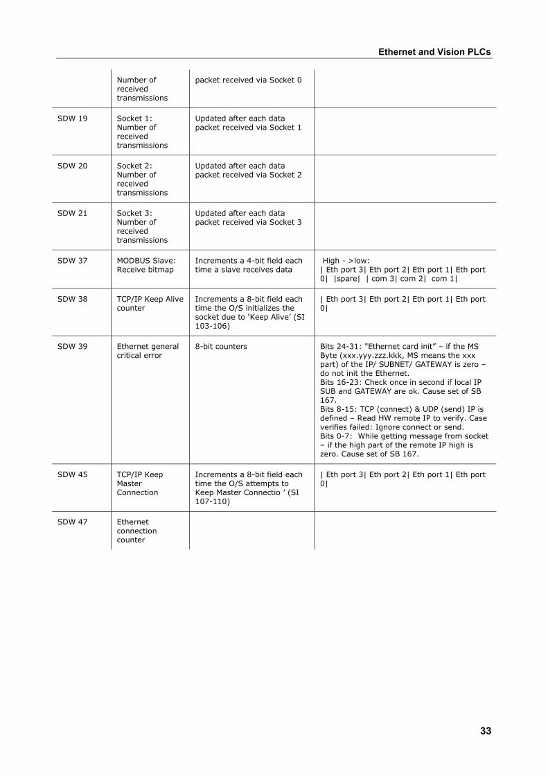
SDW 18 Socket 0: Updated after each data
Ethernet and Vision PLCs
33
Number of received transmissions
packet received via Socket 0
SDW 19 Socket 1: Number of received transmissions
Updated after each data packet received via Socket 1
SDW 20 Socket 2: Number of received transmissions
Updated after each data packet received via Socket 2
SDW 21 Socket 3: Number of received transmissions
Updated after each data packet received via Socket 3
SDW 37 MODBUS Slave: Receive bitmap
Increments a 4-bit field each time a slave receives data
High - >low: | Eth port 3| Eth port 2| Eth port 1| Eth port 0| |spare| | com 3| com 2| com 1|
SDW 38 TCP/IP Keep Alive counter
Increments a 8-bit field each time the O/S initializes the socket due to ‘Keep Alive’ (SI 103-106)
| Eth port 3| Eth port 2| Eth port 1| Eth port 0|
SDW 39 Ethernet general critical error
8-bit counters Bits 24-31: "Ethernet card init” – if the MS Byte (xxx.yyy.zzz.kkk, MS means the xxx part) of the IP/ SUBNET/ GATEWAY is zero – do not init the Ethernet. Bits 16-23: Check once in second if local IP SUB and GATEWAY are ok. Cause set of SB 167. Bits 8-15: TCP (connect) & UDP (send) IP is defined – Read HW remote IP to verify. Case verifies failed: Ignore connect or send. Bits 0-7: While getting message from socket – if the high part of the remote IP high is zero. Cause set of SB 167.
SDW 45 TCP/IP Keep Master Connection
Increments a 8-bit field each time the O/S attempts to Keep Master Connectio ’ (SI 107-110)
| Eth port 3| Eth port 2| Eth port 1| Eth port 0|
SDW 47 Ethernet connection counter
Unitronics
34
About Ethernet General information regarding the parameters required to implement Ethernet is given below. A glossary of Ethernet terms is included at the bottom of this topic. To learn how to specifically define parameters within the VisiLogic Ethernet FBs, refer to Using Ethernet.
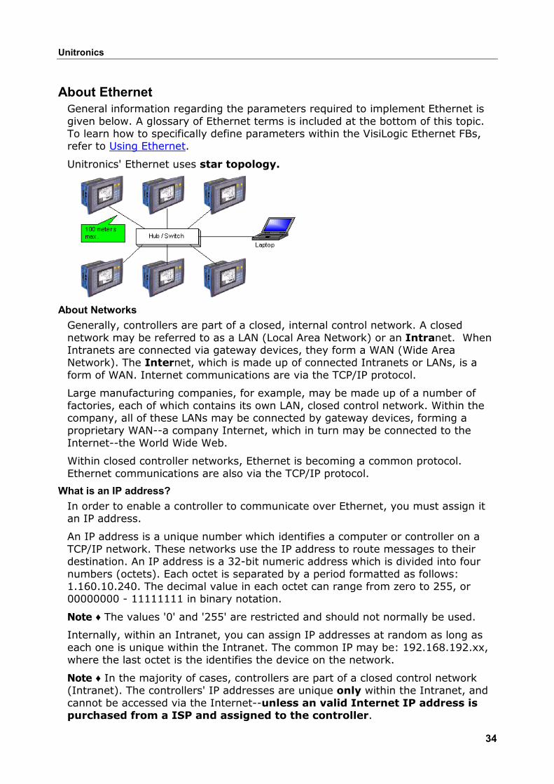
Unitronics' Ethernet uses star topology.
About Networks Generally, controllers are part of a closed, internal control network. A closed network may be referred to as a LAN (Local Area Network) or an Intranet. When Intranets are connected via gateway devices, they form a WAN (Wide Area Network). The Internet, which is made up of connected Intranets or LANs, is a form of WAN. Internet communications are via the TCP/IP protocol.
Large manufacturing companies, for example, may be made up of a number of factories, each of which contains its own LAN, closed control network. Within the company, all of these LANs may be connected by gateway devices, forming a proprietary WAN--a company Internet, which in turn may be connected to the Internet--the World Wide Web.
Within closed controller networks, Ethernet is becoming a common protocol. Ethernet communications are also via the TCP/IP protocol.
What is an IP address? In order to enable a controller to communicate over Ethernet, you must assign it an IP address.
An IP address is a unique number which identifies a computer or controller on a TCP/IP network. These networks use the IP address to route messages to their destination. An IP address is a 32-bit numeric address which is divided into four numbers (octets). Each octet is separated by a period formatted as follows: 1.160.10.240. The decimal value in each octet can range from zero to 255, or 00000000 - 11111111 in binary notation.
Note ♦ The values '0' and '255' are restricted and should not normally be used.
Internally, within an Intranet, you can assign IP addresses at random as long as each one is unique within the Intranet. The common IP may be: 192.168.192.xx, where the last octet is the identifies the device on the network.
Note ♦ In the majority of cases, controllers are part of a closed control network (Intranet). The controllers' IP addresses are unique only within the Intranet, and cannot be accessed via the Internet--unless an valid Internet IP address is purchased from a ISP and assigned to the controller.
Ethernet and Vision PLCs
35
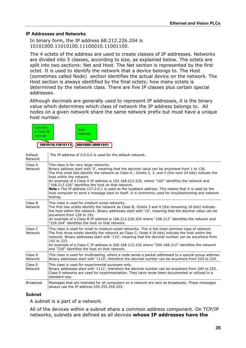
IP Addresses and Networks In binary form, the IP address 68.212.226.204 is 10101000.11010100.11100010.11001100.
The 4 octets of the address are used to create classes of IP addresses. Networks are divided into 5 classes, according to size, as explained below. The octets are split into two sections: Net and Host. The Net section is represented by the first octet. It is used to identify the network that a device belongs to. The Host (sometimes called Node) section identifies the actual device on the network. The Host section is always identified by the final octets; how many octets is determined by the network class. There are five IP classes plus certain special addresses.
Although decimals are generally used to represent IP addresses, it is the binary value which determines which class of network the IP address belongs to. All nodes on a given network share the same network prefix but must have a unique host number.
Default Network
The IP address of 0.0.0.0 is used for the default network.
Class A Network
This class is for very large networks. Binary address start with '0', meaning that the decimal value can be anywhere from 1 to 126. The first octet bits identify the network as Class A ; Octets 2, 3, and 4 (the next 24 bits) indicate the host within the network. An example of a Class A IP address is 102.168.212.226, where "102" identifies the network and "168.212.226" identifies the host on that network. Note ♦ The IP address 127.0.0.1 is used as the loopback address. This means that it is used by the host computer to send a message back to itself. It is commonly used for troubleshooting and network testing.
Class B Network
This class is used for medium-sized networks. The first two octets identify the network as Class B; Octets 3 and 4 (the remaining 16 bits) indicate the host within the network. Binary addresses start with '10', meaning that the decimal value can be anywhere from 128 to 191. An example of a Class B IP address is 168.212.226.204 where "168.212" identifies the network and "226.204" identifies the host on that network.
Class C Network
This class is used for small to medium-sized networks. This is the most common type of network. The first three octets identify the network as Class C; Octet 4 (8 bits) indicate the host within the network. Binary addresses start with '110', meaning that the decimal number can be anywhere from 192 to 223. An example of a Class C IP address is 200.168.212.226 where "200.168.212" identifies the network and "226" identifies the host on that network.
Class D Network
This class is used for multicasting, where a node sends a packet addressed to a special group address.Binary addresses start with '1110', therefore the decimal number can be anywhere from 224 to 239.
Class E Network
This class is used for experimental purposes only. Binary addresses start with '1111', therefore the decimal number can be anywhere from 240 to 255. Class E networks are used for experimentation. They have never been documented or utilized in a standard way.
Broadcast Messages that are intended for all computers on a network are sent as broadcasts. These messages always use the IP address 255.255.255.255.
Subnet A subnet is a part of a network.
All of the devices within a subnet share a common address component. On TCP/IP networks, subnets are defined as all devices whose IP addresses have the
Unitronics
36
same prefix. Devices within a particular subnet might, for example, have IP addresses that start with 100.100.100.
Subnetting enables the network administrator to further divide the host part of the address into two or more subnets. In this case, a part of the host address is reserved to identify the particular subnet.
Subnet Mask One of the crucial tasks for any router is knowing when a packet of information stays on its local network. For this, it uses a 'subnet mask'.
A network mask indicates which portion of the address identifies the network and which portion of the address identifies the node. Class A, B, and C networks have default masks, also known as natural masks, as shown below.
Class A: 255.0.0.0 - binary - 11111111.00000000.00000000.00000000
Class B: 255.255.0.0 - binary - 11111111.11111111.00000000.00000000
Class C: 255.255.255.0 - binary - 11111111.11111111.11111111.00000000
Since class C networks are the most common type, the most commonly used subnet mask usually reads "255.255.255.xx.". This tells the router that all messages with the sender and receiver having an address sharing the first three groups of numbers are on the same network, and shouldn't be sent out to another network. For example: The computer at address 192.168.192.254 sends a request to the computer at 192.168.192.252. The router, which sees all the packets, matches the first three groups in the address of both sender and receiver (192.168.192.), and keeps the packet on the local network.
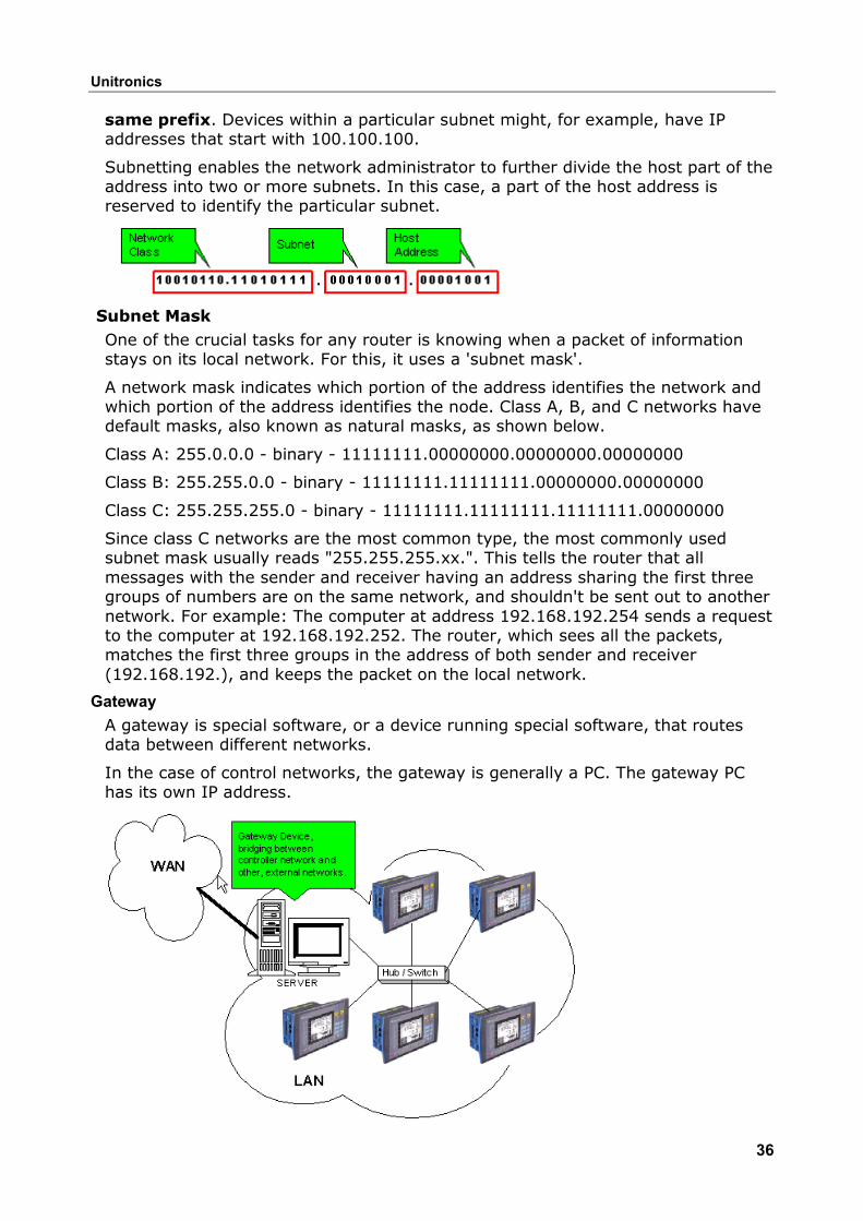
Gateway A gateway is special software, or a device running special software, that routes data between different networks.
In the case of control networks, the gateway is generally a PC. The gateway PC has its own IP address.
Ethernet and Vision PLCs
37
For example, a proxy server provides a gateway between a private network to the Internet. The proxy server is configured to enable a workstation to communicate with remote services on the Internet. In this case, the gateway acts as a barrier that allows a device to request information from the Internet and to receive information, but does not allow access to the host network by unauthorized users.
Note ♦ The IP address assigned to the gateway device is generally the last available address.
Socket A software mechanism that connects an application to a network protocol. A program can, for example, send and receive TCP/IP messages by opening a socket and reading and writing data to and from the socket. Note that a socket is a software object, not a physical component.
Note that when TCP is used, the formal 'handshake' required by the protocol means that when communications are flowing through via a defined socket, other communications cannot flow through this same socket until the current session has been terminated.
However, note that communication can flow through other sockets.
Such is not the case with UDP. Since there is no formal handshake, communications can continue to flow through a socket even when there are multiple requests.
Protocols: UDP and TCP UDP stands for User Datagram Protocol. It is a connectionless protocol that, like TCP, runs on top of IP networks. Unlike TCP/IP, UDP/IP provides very few error recovery services, offering instead a direct way to send and receive datagrams over an IP network. It's used primarily for broadcasting messages over a network.
Note ♦ In Unitronics' implementation of Ethernet, UDP is a secure protocol. Here, UDP runs under MODBUS as well as under Unitronics' proprietary protocols; these additional layers provide the level of data security required by control applications.
TCP stands for Transmission Control Protocol. TCP is one of the main protocols in TCP/IP networks. Whereas the IP protocol deals only with packets, TCP enables two hosts to establish a connection and exchange streams of data. TCP guarantees delivery of data and also guarantees that packets will be delivered in the same order in which they were sent.
UDP takes messages from application process, attaches source and destination port number fields for the multiplexing/demultiplexing service, adds two other fields of minor importance, and passes the resulting "segment" to the network layer. The network layer encapsulates the segment into an IP datagram and then makes a best-effort attempt to deliver the segment to the receiving host. If the segment arrives at the receiving host, UDP uses the port numbers and the IP source and destination addresses to deliver the data in the segment to the correct application process. Note that with UDP there is no handshaking between sending and receiving transport-layer entities before sending a segment. For this reason, UDP is said to be connectionless.
TCP uses a three-way handshake before it starts to transfer data. UDP just blasts away without any formal preliminaries. Thus UDP does not introduce any delay to establish a connection. This is probably the principle reason why DNS runs over
Unitronics
38
UDP rather than TCP -- DNS would be much slower if it ran over TCP. HTTP uses TCP rather than UDP, since reliability is critical for Web pages with text. But the TCP connection establishment delay in HTTP is an important contributor to the "world wide wait".
TCP maintains connection state in the end systems. This connection state includes receive and send buffers, congestion control parameters, and sequence and acknowledgment number parameters. UDP, on the other hand, does not maintain connection state and does not track any of these parameters. For this reason, a server devoted to a particular application can typically support many more active clients when the application runs over UDP rather than TCP.
The TCP segment has 20 bytes of header overhead in every segment, whereas UDP only has 8 bytes of overhead.
TCP has a congestion control mechanism that throttles the sender when one or more links between sender and receiver becomes excessively congested. This throttling can have a severe impact on real-time applications, which can tolerate some packet loss but require a minimum send rate. On the other hand, the speed at which UDP sends data is only constrained by the rate at which the application generates data, the capabilities of the source (CPU, clock rate, etc.) and the access bandwidth to the Internet. We should keep in mind, however, that the receiving host does not necessarily receive all the data - when the network is congested, a significant fraction of the UDP-transmitted data could be lost due to router buffer overflow. Thus, the receive rate is limited by network congestion even if the sending rate is not constrained.
Local Port In TCP/IP and UDP networks, a port is an endpoint to a logical connection and the way a client program specifies a specific server program on a computer in a network.
The port numbers are divided into three ranges: the Well Known Ports, the Registered Ports, and the Dynamic and/or Private Ports.
The Well Known Ports, sometimes called the contact port, are those from 0 through 1023. The Well Known Ports numbers are assigned by the IANA and on most systems can only be used by system (or root) processes or by programs executed by privileged users. Note ♦ Port 502 is reserved for SCADA.
The Registered Ports are those from 1024 through 4915. The Registered Ports are listed by the IANA and on most systems can be used by ordinary user processes or programs executed by ordinary users.
The Dynamic and/or Private Ports are those from 49152 through 65535
To the extent possible, these same port assignments are used with the UDP [RFC768].
Port Number Description 1 TCP Port Service Multiplexer (TCPMUX) 5 Remote Job Entry ( RJE) 7 ECHO 18 Message Send Protocol ( MSP) 20 FTP -- Data
Ethernet and Vision PLCs
39
21 FTP -- Control 22 SSH Remote Login Protocol 23 Telnet 25 Simple Mail Transfer Protocol ( SMTP) 29 MSG ICP 37 Time 42 Host Name Server ( Nameserv) 43 WhoIs 49 Login Host Protocol ( Login) 53 Domain Name System (DNS) 69 Trivial File Transfer Protocol ( TFTP) 70 Gopher Services 79 Finger 80 HTTP 103 X.400 Standard 108 SNA Gateway Access Server 109 POP2 110 POP3 115 Simple File Transfer Protocol ( SFTP) 118 SQL Services 119 Newsgroup ( NNTP) 137 NetBIOS Name Service 139 NetBIOS Datagram Service 143 Interim Mail Access Protocol ( IMAP) 150 NetBIOS Session Service 156 SQL Server 161 SNMP 179 Border Gateway Protocol ( BGP) 190 Gateway Access Control Protocol ( GACP) 194 Internet Relay Chat ( IRC) 197 Directory Location Service ( DLS) 389 Lightweight Directory Access Protocol ( LDAP) 396 Novell Netware over IP 443 HTTPS 444 Simple Network Paging Protocol ( SNPP) 445 Microsoft-DS 458 Apple QuickTime 502 MODBUS 546 DHCP Client 547 DHCP Server 563 SNEWS 569 MSN 1080 Socks
Unitronics
40
Glossary ARP
Address Resolution Protocol associates an IP address to a hardware address by requesting the sending machine for additional information called a MAC address. This only applies to Ethernet based networks.
Client
The client is generally an application that runs on a personal computer or workstation and relies on a server to perform some operations. For example, an e-mail client is an application that enables you to send and receive e-mail.
Client/server architecture
In this type of network architecture, each computer or process on the network is either a client or a server. Servers are powerful computers or processes dedicated to managing disk drives (file servers), printers (print servers), or network traffic (network servers ). Clients are PCs or workstations on which users run applications. Clients rely on servers for resources, such as files, devices, and even processing power.
Another type of network architecture is known as a peer-to-peer architecture because each node has equivalent responsibilities. Both client/server and peer-to-peer architectures are widely used, and each has unique advantages and disadvantages.
DHCP
Dynamic Host Configuration Protocol is a protocol for organizing and simplifying the administration of IP addresses for local machines. In many cases (such as with WinRoute) A DHCP server is built into the gateway for further simplification.
DNS
Domain Name System is a naming scheme for IP addressing. For example www.kerio.com is a domain name and has an associated IP address. A DNS server matches domain names to an IP address. We use the domain name system because it is easier to remember a domain name than a string of numbers.
Firewall
A filtering module located on a gateway machine that examines all incoming and outgoing traffic to determine if it may be routed to its destination. WinRoute Lite is a simple Firewall based on Network Address Translation.
Gateway
The point of entrance from one network to another. A gateway is responsible for the proper distribution of data coming in and going out of a local area network. WinRoute must be installed on the gateway machine, also referred to as the host computer or network router.
ICMP
Internet Control Message Protocol uses datagrams to report errors in transmission between the host and the gateway.
IP address
Ethernet and Vision PLCs
41
An IP address is the unique 32-bit number, which identifies a computer in a network. In order to communicate across wide area networks, each computer must have a unique IP address. Local area networks cannot directly communicate across wide area networks because they are defined by a private class of IP's.
Local Area Network
A Local Area Network (LAN) is a group of interconnected computers with the ability to share resources without having to access a wide area network.
MAC Address
A Media Access Control (MAC) address is a hard-coded interface identification used by layer 2 devices (switch or bridge) for proper forwarding of frames between computers on a network.
NAT
Network Address Translation is an Internet standard that enables a local-area network (LAN) to use one set of IP addresses for internal traffic and a second set of addresses for external traffic. A NAT box located where the LAN meets the Internet makes all necessary IP address translations.
NAT serves three main purposes:
Provides a type of firewall by hiding internal IP addresses
Enables a company to use more internal IP addresses. Since they're used internally only, there's no possibility of conflict with IP addresses used by other companies and organizations.
Allows a company to combine multiple ISDN connections into a single Internet connection.
Network interface
A network interface may be an Ethernet card, modem, ISDN card, etc. The computer sends and receives packets by means of the network interface.
Network Mask
A Network mask is used to group IP addresses together. Routers use a subnet mask to define the group (or IP subnet) to which an IP address belongs so that it can identify the correct interface from which it should forward an IP packet.
Packet
When data is transmitted over the network it is broken up into smaller pieces called packets and individually routed to their destination. This way if one packet is not properly received, the receiving party can request resubmission of the single packet, as opposed to the entire piece of data. Each packet contains headers, which are responsible for the successful transmission of the packet, and a data part, which contains a portion of the original data being transmitted over the network. The term packet is used when referring to layer 3 devices (i.e. a router). A frame is the term used when referring to layer two devices (i.e. a switch).
Peer-to-peer architecture
A type of network in which each workstation has equivalent capabilities and responsibilities. This differs from client/server architectures, in which some computers are dedicated to serving the others. Peer-to-peer networks are generally simpler, but they usually do not offer the same performance under heavy loads.
Unitronics
42
Port
A port, in terms of TCP/IP, is a 16-bit number (the allowed range being 1 through 65535) used by the protocols of the transport layer - the TCP and UDP protocols. Ports are used to address applications. In other words, when a packet is received by the computer, the operating system uses port information to determine which application will receive the data within the packet.
Port Mapping
Port mapping is an advanced feature of WinRoute that allows servers to be hosted securely behind NAT. When a packet is received by the WinRoute host it can be forwarded (by translating the destination information in the packet header) to another computer in the local network.
Protocol
Defines rules for the transmission of data.
RAS
Remote Access Service refers to the ability to dial into another computer or network remotely. In the context of WinRoute, RAS simply refers to a dial-up connection.
TCP/IP
TCP/IP is a suite of networking protocols used for communication across networks. It is the standard form of communication over the Internet. The two most significantly used Internet Protocols are TCP and UDP. Transmission Control Protocol (TCP) is a connection oriented protocol intended to provide reliability and to ensure that all data is transferred successfully from one computer to another. User Datagram Protocol (UDP) is a connectionless protocol that does not require any confirmation from the receiving party. UDP is more commonly used for multimedia and streaming applications.
43
IndexCCommunications.... 10, 11, 12, 13, 19,
22, 24, 27 Network................ 1, 10, 11, 12, 34
Eemail ...........................................15 e-mail ..........................................15 Ethernet.1, 10, 11, 12, 13, 19, 22, 24,
27, 28, 34 FFavorites ......................................19 IIP Addresses.................................19
NNetwork .................................11, 12 PPC COM Parameters...................... 19 Project ........................................ 19 SSocket ........................................ 12 System Operands ......................... 28 TTCP/IP .10, 11, 12, 13, 15, 19, 22, 24,
27, 28 Troubleshooting ........................... 28