Embed Size (px)
DESCRIPTION
Red Ethernet
Citation preview
EtherNet/IP Design and Configuration
Designing an EtherNet/IP Cable System
Pinging a Module’s EtherNet/IP Address
Configuring and Modifying EtherNet/IP Addresses Using
BOOTP-DHCP Server Software
Configuring and Modifying EtherNet/IP Addresses Using
RSLinx Software
Producing and Consuming Data over an EtherNet/IP Network

2
EtherNet/IP Network Overview CIP (Common Industrial Protocol):
• Enables I/O control over an EtherNet/IP network • Bridges EtherNet/IP devices with devices on
networks such as ControlNet and DeviceNet that also use CIP at the application layer
Tip: Standard EtherNet/IP and Ethernet CIP safety modules can communicate on the same network.

3
EtherNet/IP Network Overview
OSI (Open System Interconnection) Model:
• Consists of seven layers
• Each layer uses services of layer below it and supplies higher level services to layer above it to communicate

4
EtherNet/IP Network Overview
IP Network
TCP, UDP Transport
Session
Presentation CIP, CSP, HTTP
FTP,TELNET
Application
Protocol Layer
Correlating the seven layers with common protocols:
10/100baseT, Transceiver, etc.
Physical
Ethernet Data Link

5
EtherNet/IP Network Hardware Components
Switch:
Incoming messages
are only transmitted
to desired node.
Switches selectively
route packets of
information to specific
devices.

6
Switch Selection
Benefits of a managed switch: • Monitor the performance of the network
• Set up broadcast domains
• Run single computers on managed switch ports

7
Switch Selection
VLAN (Virtual (or logical) Local Area Network):
Accounting Engineering
Production Human Resources
• Can change or add workstations
• Can manage load balancing and bandwidth allocation more easily than with a physical picture of the LAN:

8
Switch Selection
Controller 1 PC Controller 2
VLAN 1 VLAN 2
I/O I/O I/O I/O
I/O
1 3 2
4 5 6 7 8
With VLANs, a switch can be configured to share two isolated networks without the traffic from one network burdening the other.

9
Copper Cabling
Shielded cables should not be used in
environments that are likely to have
ground offsets due to electrical storms or
poorly grounded buildings/installations.
Two types of copper cabling:
– Shielded, balanced twisted-pair (STP/ScTP)
– Unshielded twisted pair (UTP)

10
EtherNet/IP Network Topologies
Bus Topology:
Tip: This topology is used with many existing Ethernet network architectures but it is seldom used in new architectures.
• Are used when coax media is desired

11
EtherNet/IP Network Topologies
Star Topology:
Tip: This is the most common topology used in EtherNet/IP network architectures.
• Best suited for environments using twisted pair and/or fiber optic wire

12
EtherNet/IP Network Topologies Tree (Combination) Topology:
Tip: The tree topology should also be given careful consideration when designing an EtherNet/IP network as it effectively blends the advantages of a star and bus topology.

13
Overview of IP Addresses
IP (Internet Protocol) Address:
• User-defined software address assigned to a device
• Identifies network and node
• 32-bit address normally grouped into 4 bytes (e.g., 10.88.244.130).

14
Overview of IP Addresses
Sample view of an IP address (131.107.16.200)

15
Overview of IP Addresses
MAC (Media Access Control) Address:
MAC Address (also referred to as a module's Ethernet address)

16
Classes of IP Addresses
Four different classes of IP addresses:
Net ID Host ID 0 1 1 Class C
Net ID Host ID 0 1 Class B
Net ID Host ID 0
0 1 2 8 16 24 31
Class A
Class D Used for Multicast Messages
• IP address used determines number of possible networks and end devices.
• Classes are determined by first few bits of each IP address:

17
Classes of IP Addresses
Class Initial Byte Values Typical Users/Uses
A 1 - 127 Very large networks
B 128 - 191 Medium-sized networks
C 192 - 223 Small to mid-size businesses
D 224 - 239 Multicast messaging

18
Private IP Addresses
Class Private IP Addresses
A 10.0.0.0 - 10.255.255.255
B 172.16.0.0 - 172.31.255.255
C 192.168.0.0 - 192.168.255.255
• Finite number of IP addresses have been designated as private IP
addresses.
• Private IP addresses prohibit message traffic from being routed to Internet
thereby avoiding conflicts that would otherwise arise whenever two or more
enterprises used same IP address.
19
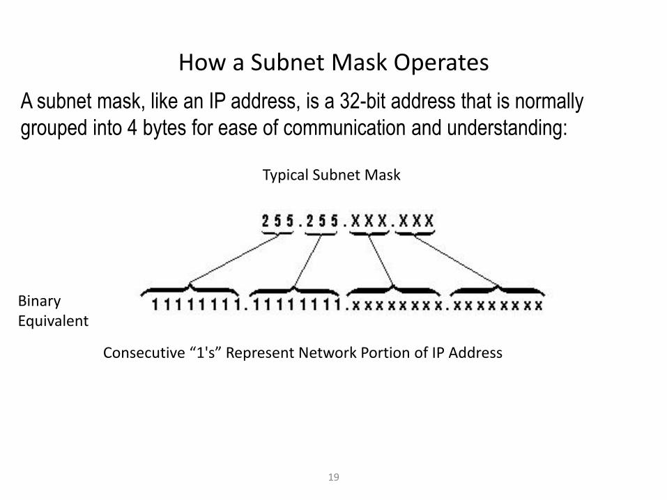
How a Subnet Mask Operates
A subnet mask, like an IP address, is a 32-bit address that is normally
grouped into 4 bytes for ease of communication and understanding:
Typical Subnet Mask
Binary Equivalent
Consecutive “1's” Represent Network Portion of IP Address

20
How a Subnet Mask Operates
A subnet mask uses "1's" to do bit-by-bit comparison of two IP addresses to
see if devices associated with IP address are on same subnet:
• As long as IP address bits match each other (independent of the subnet
mask value) whenever there is a corresponding “1” in the subnet mask,
devices are on same subnet.
• If network portions:
– Match up, devices communicate directly with each other
– Don't match up, they are on separate networks and then communicate through a
router (commonly referred to as a gateway).

21
Example
Compare addresses of 2 devices and determine if they are on same subnet:
EtherNet/IP Address: 165.88.73.129
EtherNet/IP Address: 165.88.74.187
Subnet Mask: 255.255.240.0
Converting these decimal values to their binary equivalent yields:
EtherNet/IP Address:
EtherNet/IP Address:
Subnet Mask:
Corresponding bits match each other; therefore, these two devices are on the same subnet.
22
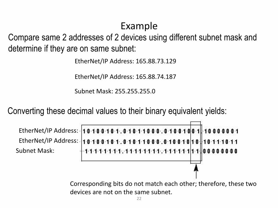
Example Compare same 2 addresses of 2 devices using different subnet mask and
determine if they are on same subnet:
EtherNet/IP Address: 165.88.73.129
EtherNet/IP Address: 165.88.74.187
Subnet Mask: 255.255.255.0
Converting these decimal values to their binary equivalent yields:
EtherNet/IP Address:
EtherNet/IP Address:
Subnet Mask:
Corresponding bits do not match each other; therefore, these two devices are not on the same subnet.

23
Ping
Ping Command
Device Is Active on the Network
Device Is Not Active on the
Network

24
Ping
Successful (ping) returns are an indication that:
A successful ping command does not
guarantee that a particular device is active.
A successful ping identifies that a device
with the identified IP address is active on the
network.
• A device is active on the network with the IP address used by the ping
command.
• Error is not caused by a faulty cable
• Error is not the result of a problem with the router or switch

25
ARP (Address Resolution Protocol)
The arp (arp -a) command is a protocol for mapping an Internet Protocol
address (IP address) to a MAC address that is recognized in the local network.
To be most effective in mapping the two different addresses together, it should
be executed after the ping command has been executed on one or more IP
addresses.
IP and MAC address pairing list

26
BOOTP-DHCP Server Software
• BOOTP (Bootstrap Protocol)
• BOOTP Server
• BOOTP-DHCP (Bootstrap Protocol-Dynamic Host Configuration Protocol) Server Software

27
BOOTP-DHCP Server Software
Relation List:
• Entering corresponding MAC and IP addresses into BOOTP table allows
simultaneous assignment of IP addresses to multiple modules.
Address assignments do not take
effect unless the device is
configured for BOOTP operation
and a power-cycle occurs on the
device.

28
BOOTP-DHCP Server Software
BOOTP-DHCP Server software main window:
Relation List Pane
Relation List
Request History
Pane
Request Type

29
BOOTP-DHCP Server Software
• in BOOTP Server by right-clicking an entry in the Relation List and
selecting Reset Module's Network Settings to Factory Defaults
• in the RSWho window of RSLinx software via the Module Configuration
dialog box
Tip: BOOTP-DHCP Server can only change a device's IP address if its
setting for Network Configuration Type is dynamic (obtain IP address from
BOOTP Server). This setting can be restored using one of the following
methods:

Copyright © 2008 Rockwell Automation, Inc. All rights reserved.
30
BOOTP-DHCP Server Software
BOOTP-DHCP Server software configuration screens:
Relationship between a Device's MAC Address and its IP Address
Network and Host Part Identification
Address of Gateway (or Router) Capable of Routing Messages to Remote Network

31
RSLinx Software
From within the RSLinx RSWho window, a module’s EtherNet/IP address or subnet mask can be modified.
32
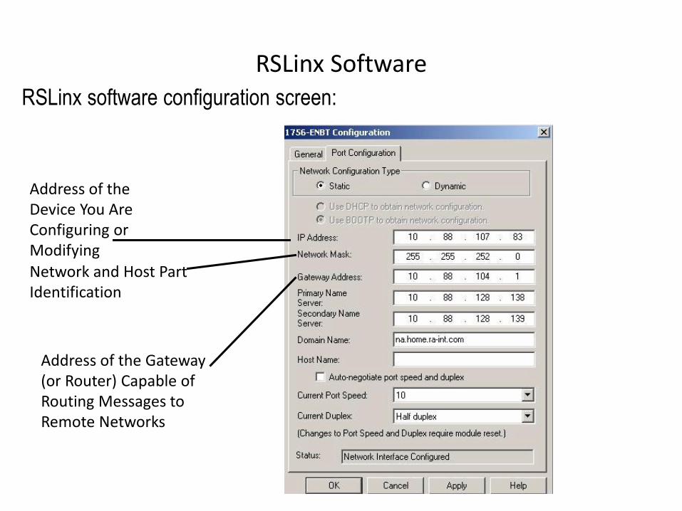
RSLinx Software
RSLinx software configuration screen:
Address of the Device You Are Configuring or Modifying
Network and Host Part Identification
Address of the Gateway (or Router) Capable of Routing Messages to Remote Networks

33
Produce/Consume Model Communication model based on content of data rather than source or destination of data:
• Devices that need data (consumers) recognize data they need and consume it (at a specified rate).
• Data is sent on network in single message, no matter how large the number of nodes to which it
needs to go.
• All consumer nodes receive and “consume” information simultaneously.
• Receipt of information is synchronized:
– Bandwidth is conserved since information is "produced" once to multiple
“consumers.”

34
Produce/Consume Model
To limit the number of connections
used, consider grouping data into
an array or a user-defined data type
and producing only that array or
structure.

35
Produced and Consumed Tag Requirements
• Tags must be data type that is:
– 32 bits or larger (e.g., DINT, REAL, TIMER, COUNTER, etc.)
– Array of these data types
– User-defined data type.
• Data must be less than or equal to 500 bytes.
Data that meets following requirements can be shared by controllers without using ladder logic (i.e.,
message instructions):

36
Produced and Consumed Arrays
• Create user-defined data type containing single member:
– Make single member array of desired type
• Copy this user-defined data type to both controllers
• Produce and consume tags of this data type
If a user-defined structure is
produced, there must be a structure
with the identical size and layout in
the consuming controller. To ensure
accuracy, copy the structures
between projects.
BOOL, SINT, and INT arrays can be indirectly produced and consumed:

37
Produced and Consumed Arrays
38
Produced and Consumed Arrays
• Define a user-defined data type with two members:
– Name first member Status and assign it a DINT data type
– Make second member an array of INTs
You can consume an array of INTs from a PLC-5C controller over a ControlNet network:

39
Creating a Produced Tag
Produce Option
Maximum Number of Consumers
Tag Name - Required to Configure Consumed Tag(s)

40
Creating a Consumed Tag
Must Be in Consuming Controller's I/O Configuration
Tag Name
RPI for Consumed Tag
Exact Match Required
Must Be Exact Name of the Produced Tag

41
Creating a Consumed Tag
A produced tag should be
consumed by only one tag in a
consuming controller. Multiple
consumed tags within a controller
using the same produced tag will
result in unpredictable controller-to-
controller behavior.
If a consumed tag connection
faults, all other tags being
consumed from the producing
controller will also stop receiving
data.

42
Creating a Consumed Tag
The Remote Data (source tag
name) must be exactly the same as
the produced tag name in the
producing controller.
Tip: For accuracy, the source project should be opened and the tag names should be copied.