Embed Size (px)
Citation preview
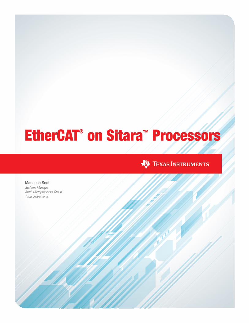
EtherCAT® on Sitara™ Processors
Maneesh SoniSystems Manager Arm® Microprocessor GroupTexas Instruments
2 EtherCAT® on Sitara™ Processors December 2017
EtherCAT® is among the leading communications standards based on Ethernet that is used increasingly for networking and communications in the industrial or factory environment.
The EtherCAT communication technology was invented by Beckhoff Automation in
Germany and later standardized by the EtherCAT Technology Group (ETG).
Texas Instruments, Inc. (TI) is the first semiconductor company to license EtherCAT
technology. TI has integrated EtherCAT into several Sitara™ processors, including
the AM335x Arm® Cortex-A8, AMIC110 Arm Cortex-A8, AM437x Arm Cortex-A9,
and the AM57x Arm Cortex-A15 devices. To enable EtherCAT, TI has built upon
its programmable real-time unit (PRU) technology to create a unified front-end for
industrial communications and bring EtherCAT and other industrial standards to its
growing platform of Arm-based microprocessors.
TI has also brought the software, hardware and
tools together to streamline the development of
EtherCAT-based products with Sitara devices.
Additionally, the industrial grade temperature and
long life-cycle support make Sitara a compelling
choice for EtherCAT and other industrial networking
applications.
The integration of EtherCAT into Sitara processors
enables best-in-class functionality at lower cost.
For example, the Sitara AM335x processor-based
integration of EtherCAT meets or exceeds all
required features and performance benchmarks,
including key EtherCAT features such as distributed
clocking and end-to-end latency of less than 700
nanoseconds (ns). In addition to the capabilities of
Sitara processors, TI streamlines the development of
EtherCAT products by supporting design engineers
with a wide range of related software, hardware and
development tools.
Introduction to EtherCAT
EtherCAT (Ethernet for Control Automation
Technology) is a real-time industrial Ethernet
standard for industrial automation applications,
such as input/output (I/O) devices, sensors and
programmable logic controllers (PLCs). It was
originally developed by Beckhoff Automation GmbH
but is now overseen by the EtherCAT Technology
Group that was set up to help with proliferation
of the EtherCAT standard. Today, there are over
1,900 member companies from 52 countries that
create and deploy EtherCAT-compatible products.
Ethernet has seen unparalleled adoption in diverse
applications, but in industrial environments it is
still not efficient enough for small amounts of data
exchange, it has low determinism for real-time
operation, and it works with only star topology
in which the network nodes must be connected
through switches. EtherCAT technology adds
certain features on Ethernet and enforces certain
3 EtherCAT® on Sitara™ Processors December 2017
configurations to make it a very efficient network
technology for automation while fully conforming
to the Ethernet specifications. The design of
EtherCAT enables any standard PC to be used
as an EtherCAT master and communicate with
EtherCAT slaves, which are specialized devices
compliant with the EtherCAT specification. Together,
the master and slave EtherCAT devices can be used
in all devices in the factory network – automation
controllers, operator interfaces, remote input/output
units, sensors, actuators, drives and others.
Technology
EtherCAT improves upon traditional Ethernet by
implementing “on-the-fly” processing where the
nodes in the EtherCAT network read the data from
a frame as it passes through. All EtherCAT frames
originate from the EtherCAT master which sends
commands and data to the slaves. Any data to be
sent back to master is written by the slave into the
frame as it passes through.
This helps eliminate the need for point-to-point
exchange of small-sized frames between master
and individual slaves and drastically improves the
efficiency of communication. However, it also means
that each slave must have two Ethernet ports and
be able to let the frame pass through while reading
from or writing to the passing frame and therefore,
specialized hardware is required in the slave devices.
As a result of these improvements, the usable
bandwidth in a 100-Mbps network running EtherCAT
is more than 90 percent as compared to less than
5 percent for networks where the master must
separately communicate with each slave node.
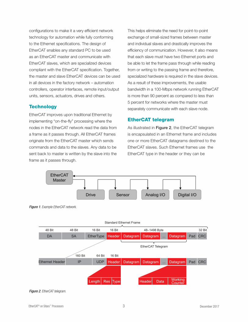
EtherCAT telegram
As illustrated in Figure 2, the EtherCAT telegram
is encapsulated in an Ethernet frame and includes
one or more EtherCAT datagrams destined to the
EtherCAT slaves. Such Ethernet frames use the
EtherCAT type in the header or they can be
Figure 1. Example EtherCAT network.
Figure 2. EtherCAT telegram.
Drive Sensor Digital I/OAnalog I/O
EtherCAT Master
DA
Ethernet Header IP UDP
48 Bit 48 Bit
160 Bit 64 Bit 16 Bit
16 Bit 16 Bit 32 Bit
Standard Ethernet Frame
EtherCAT Telegram
48–1498 Byte
SA EtherType Header Datagram Datagram Datagram Pad CRC...
Header Datagram Datagram Datagram Pad
WorkingCounterDataHeaderLength Res Type
CRC...
4 EtherCAT® on Sitara™ Processors December 2017
packed with the IP/UDP header. When the IP
header is used, the EtherCAT protocol can also be
used across network routers.
Each EtherCAT datagram is a command that consists
of a header, data and a working counter. The header
and data are used to specify the operation that the
slave must perform, and the working counter is
updated by the slave to let the master to know that
a slave has processed the command.
Protocol
Each slave processes EtherCAT packets “on-the-
fly” in that it receives the frame, parses it and takes
action if the address specified in an EtherCAT
datagram matches its own address, and forwards
the entire datagram from its second port while also
updating the contents and the CRC of the packet.
Through the datagrams, the EtherCAT master
addresses the entire address space of up to 4 GB
in which up to 65,536 EtherCAT slaves, each with
65,536 addresses, can be located. The EtherCAT
datagrams do not have any restriction on the order
in which the slaves are addressed with respect to
the actual position of slave nodes in the network.
There are different types of EtherCAT data
transmissions – cyclic and acyclic. Cyclic data are
the process data that are transferred at periodic
intervals or cycle times. Acyclic data is usually non-
time-critical data that can be large in size and usually
exchanged in response to a controller command.
Some acyclic data, such as diagnostic data, can be
critical and have demanding timing requirements.
EtherCAT handles these different data transmission
requirements through optimized addressing
schemes – physical addressing, logical addressing,
multiple addressing and broadcast addressing.
To handle various addressing schemes, each slave
has a fieldbus memory management unit (FMMU).
The FMMU units in each slave enable the EtherCAT
protocol to treat various slave devices as part of
a 4-GB large memory space with slave spaces
mapped in it. The EtherCAT master assembles a
complete process image during the initialization
phase and then makes even bit-level accesses
to slave devices via a single EtherCAT command.
This capability makes it possible to communicate
practically with any number of input/output (I/O)
channels across large and small devices spanning
the entire fieldbus network via a standard Ethernet
controller and standard Ethernet cable.
Performance
As a result of hardware-based FMMU and on-the-
fly processing, the EtherCAT network performs at
very high levels of efficiency. It enables cycle times
of the order of microseconds to communicate from
controllers to field devices. The communication
efficiency is no longer a bottleneck in industrial
networks and brings it in line with the computation
speeds of contemporary industrial PCs. For
instance, the increased performance makes it
possible to run the current loop, in addition to the
position loop, for distributed drives over EtherCAT.
Topology
The EtherCAT standard supports any topology –
line, star or tree – and the bus structures common
in fieldbus networks can also be realized with
EtherCAT. Since the EtherCAT interface is present
on I/O devices, there is no requirement for any
Ethernet switching hardware. With the 100-m range
of copper links and even longer with optical links,
EtherCAT can span over thousands of devices
spread across a large geographical area. For short
distances, such as on back-plane, EtherCAT uses
E-bus, a differential signaling technology.
5 EtherCAT® on Sitara™ Processors December 2017
Distributed clocking
To realize simultaneous actions in industrial nodes
installed away from each other, it is necessary
to synchronize their internal clocks. EtherCAT
accomplishes this by sampling the timestamps for
the ingress and egress of an EtherCAT packet on
every slave node as it traverses the network. The
master uses the timestamp information provided by
the slaves to accurately calculate the propagation
delay for each individual slave. The clocks in each
slave node are adjusted based on this calculation
and thus, these clocks are synchronized to within
1 μs of each other. An additional advantage
of the accurately synchronized clocks is that
any measurements taken can be linked to the
synchronized time and remove the uncertainty
associated with the jitter in the communication
between devices.
Device profiles
In industrial automation, use of device profiles is a
very common method to describe the functionality
and parameters of the devices. EtherCAT provides
interfaces to existing device profiles so that legacy
fieldbus devices can be easily upgraded to use
EtherCAT. Some of such interfaces are CAN
application layer over EtherCAT (CoE) and Servo
drive profile over EtherCAT (SoE) that enable use of
CANOpen® and SERCOS® by taking advantage of
the mapping of their data structures to EtherCAT.
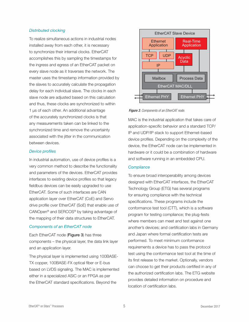
Components of an EtherCAT node
Each EtherCAT node (Figure 3) has three
components – the physical layer, the data link layer
and an application layer.
The physical layer is implemented using 100BASE-
TX copper, 100BASE-FX optical fiber or E-bus
based on LVDS signaling. The MAC is implemented
either in a specialized ASIC or an FPGA as per
the EtherCAT standard specifications. Beyond the
MAC is the industrial application that takes care of
application-specific behavior and a standard TCP/
IP and UDP/IP stack to support Ethernet-based
device profiles. Depending on the complexity of the
device, the EtherCAT node can be implemented in
hardware or it could be a combination of hardware
and software running in an embedded CPU.
Compliance
To ensure broad interoperability among devices
designed with EtherCAT interfaces, the EtherCAT
Technology Group (ETG) has several programs
for ensuring compliance with the technical
specifications. These programs include the
conformance test tool (CTT), which is a software
program for testing compliance; the plug-fests
where members can meet and test against one
another’s devices; and certification labs in Germany
and Japan where formal certification tests are
performed. To meet minimum conformance
requirements a device has to pass the protocol
test using the conformance test tool at the time of
its first release to the market. Optionally, vendors
can choose to get their products certified in any of
the authorized certification labs. The ETG website
provides detailed information on procedure and
location of certification labs.
Figure 3. Components of an EtherCAT node.
EtherCAT Slave Device
EtherCAT MAC/DLL
EthernetApplication
IP
Mailbox
Ethernet PHY Ethernet PHY
Process Data
Real-TimeApplication
TCP UDP AcyclicData
6 EtherCAT® on Sitara™ Processors December 2017
Typical EtherCAT® node
A typical EtherCAT node that is in use today has
architecture similar to one of the illustrations below.
Many of the simple EtherCAT devices such as digital
I/O can be created using single FPGA or ASIC
solutions available today. A simplified version of such
architecture is shown in Figure 4. Such architecture
is well suited for cost-sensitive simple I/O nodes
that do not require software and all functionality is
implemented in hardware.
In the EtherCAT nodes where additional processing
power is needed, an external processor, often
with on-chip Flash memory, is connected to the
EtherCAT ASIC/FPGA for handling the application-
level processing. Such devices could be sensor
applications, for instance, where the processor is
required to operate the sensor, implement the device
driver and run the EtherCAT protocol stack. The cost
of such architecture is higher than that for simple
digital I/O devices and it comes with the flexibility
that developers can select a processor that suits
their needs and cost targets.
In yet another approach, the EtherCAT
implementation is one of the peripherals in the
device that has an integrated CPU. Many FPGA
devices have the capability to configure a processor
in the FPGA or already have an integrated processor.
Some vendors provide ASICs with both EtherCAT
and a suitable processor on the device. The FPGAs
are flexible but depending on the CPU selection,
there is a risk that cost or operating frequency
targets are challenging to meet.
EtherCAT solution from TI
TI has integrated EtherCAT functionality into the
Sitara processors. These devices integrate an
Arm processing core with a cornucopia of other
peripherals and interfaces that make them attractive
devices for building industrial automation equipment.
The Sitara processors integrate the programmable
real-time unit industrial communication subsystem
(PRU-ICSS), which supports very low-level
interaction with the MII interfaces. This capability
enables the PRU-ICSS to implement specialized
communication protocols such as EtherCAT.
DigitalI/O
EtherCATASIC/FPGA
PHY
PHY
EtherCATASIC/FPGAProcessor Host
Interface
PHY
PHY
Figure 4. Basic Digital I/O EtherCAT device.
EtherCATPeripheral
Arm/ProprietaryProcessor
PHY
PHY
PRU-ICSS with EtherCAT
Sitara processor
MII ×2
UART
PRU ×2SharedMemory
Arm Cortex-A
CPUPHY
PHY
Figure 5. EtherCAT with ASIC and external processor.
Figure 6. Integrated EtherCAT with processor.
Figure 7. EtherCAT slave on TI Sitara AM335x/AMIC110/AM437x/AM57x processors .
7 EtherCAT® on Sitara™ Processors December 2017
The entire EtherCAT MAC layer can be encapsulated
in the PRU-ICSS through firmware. The PRU-ICSS
processes EtherCAT telegrams on-the-fly, parses
them, decodes the address and executes
EtherCAT commands. Interrupts are used for any
communication required with the Arm processor
where the EtherCAT stack (Layer 7) and the
industrial application is running. The PRU-ICSS also
performs frame forwarding in the reverse direction.
Since the PRU-ICSS can implement all EtherCAT
functionality, the Arm processor can be utilized for
complex applications or a lower-speed Arm core
can be deployed for simpler and cost-constrained
applications, such as distributed I/O.
To complete the EtherCAT solution with the Sitara
processors, Ethernet PHY devices such as TI’s
TLK105L, TLK106L, DP836X0 , DP83822 or
DP8384x are required. For instance TLK110 is
optimized for low latency between the MII and
PHY interfaces, which is an important attribute
for EtherCAT performance. The TLK110 also has
advanced cable diagnostics features that can quickly
locate cable faults.
Sitara processors block diagram
The Sitara AMIC110 and AM335x processors are
based on Arm Cortex-A8, and the AM437x and
AM57x are based on Arm Cortex-A9 and Arm
Cortex-A15 RISC cores, respectively. All of the Sitara
processors feature a broad range of integrated
peripherals. For industrial applications, the Sitara
processors support multiple operating frequency
ranges from 300 MHz for simple applications up
to 1.5 GHz for complex applications that require
high performance, such as industrial drives. Both
the AM335x and AM437x processors at any
performance level can implement EtherCAT. The
AMIC110 and AM335x processors are configured
with one PRU coprocessor (two real-time cores) while
the AM437x and AM57x processors feature two
PRUs with a total of four real-time cores. The block
diagrams of the Sitara AMIC110, AM335x, AM437x,
and AM57x processors are shown in Figures 8, 9,
10, and 11. Additional information about all of the
devices, their on-chip peripherals and features are
available at ti.com/amic110, ti.com/am335x,
ti.com/am437x, or ti.com/am57x.
ARM
Cortex -A8
®
®
Up to 1 GHz*Graphics
AccelerationPac
SGX530
PRU
System Services
Connectivity and I/Os
Security
AccelerationPac
LCD
Controller
32K/32K L1
45 nm
Industrial
Communication
Subsystem
EtherCAT ,
PROFINET ,EtherNet/IP™
®
®
24-Bit LCD Cont.
Touch ScreenController
(1)
256K L2 w/ ECC
64K RAM
EDMA WDT RTC
NAND/
NOR
(16-Bit ECC)
MMC/
SD/SDIO
×3
McASP
×2
GPIO
UART ×6
PWM ×3EMAC
2-Port w/Switch
10/100/1Gw/ 1588
USB2OTG +PHY×2
CAN ×2
eCAP/eQEP ×3 SPI ×2
I C ×32
12-Bit ADC(1)
JTAG/ETB Timers ×8
64KB L3 Shared RAM
LPDDR1/DDR2/DDR3/DDR3L Crypto
ARM
Cortex -A9
®
®
800 MHz,
1 GHz
Graphics
Acceleration
SGX530
Quad-Core
PRU-ICSS
System Services
Connectivity and I/Os
Security
AccelerationPac
Display
Subsystem
32K/32K L1
45 nm
Industrial
Communication
Subsystem
EtherCAT ,
PROFINET ,EtherNet/IP™ +Motor feedback
protocols +Sigma Delta
®
®
24-Bit LCD
ProcessingOverlay,Resizing,
Color SpaceConversion, etc.
Touch ScreenController
256K L2/L3
64K RAM
EDMA WDT RTC
NAND/
NOR
(16-Bit ECC)
3 MMC/
SD/SDIO
McASP
×2
GPIO
UART ×6
PWM ×6CAN ×2CameraI/F (2×
Parallel)
EMAC2-PortSwitch
10/100/1Gw/ 1588
USB2OTG +PHY×2 HDQQSPI
eCAP/eQEP ×3 SPI ×5
I C ×32
2 12-Bit ADCsDebug 12 Timers SyncTimer 32KSimple Pwr Seq
256KB L3 Shared RAM
32-Bit
LPDDR2/DDR3/DDR3L Crypto, Secure Boot
Figure 8. AM335x processor block diagram.
Figure 9. AM437x Sitara processor block diagram.* 800 MHz / 1 GHz only available on 15×15 package. 13×13 supports up to 600 MHz.(1) Use of TSC will limit available ADC channels.
8 EtherCAT® on Sitara™ Processors December 2017
EtherCAT software architecture
Three major software components comprise an
EtherCAT slave implementation on one of TI’s
Sitara processors. The first is the micro-code that
implements Layer 2 functionality in the PRU; the
second is the EtherCAT slave stack that runs on
the Arm processor and the third is an industrial
application that is dependent on the end equipment
in which this solution is used. Additional
supporting components, such as the
protocol adaptation layer and device
drivers are provided by TI in the
Processor Software Development Kit
(SDK). Irrespective of whether a TI-tested
EtherCAT stack is used or another, the
architecture illustrated in Figure 12 on
the following page is designed to work
without changes. This EtherCAT solution
is also independent of the OS and any
adaptations can be made by referring to
the PRU-ICSS firmware API guides.
In EtherCAT Layer 2, the PRU real-time
cores share the tasks of datagram
processing, distributed clocking, address
mapping, error detection and handling
and host interface.
PRUs also emulate EtherCAT register space in the
internal shared memory. With their deterministic
realtime processing capability, the PRUs handle
EtherCAT datagrams with consistent and predictable
processing latency. The Sitara processor with TI’s
DP83822 Ethernet PHY device exhibits a low latency
which makes TI’s implementation one of the leading
EtherCAT slave solutions.
ARMCortex -A8
®
®
300 MHz
PRU-ICSS
System Services
Connectivity and I/Os
32K/32K L1
45 nm
IndustrialCommunication
SubsystemEtherCAT ,
PROFINET ,EtherNet/IP™,
PROFIBUS,HSR/PRPand more
®
®
256K L2 w/ ECC
64K RAM
EDMA WDT RTC
GPMC/NAND/NOR(16-Bit ECC)
MMC/SD/SDIO
×3
McASP×2
GPIO
UART ×6
USB2OTG +PHY×2
CAN ×2
PWM ×3
SPI ×2
I C ×32
12-Bit ADC(1)JTAG/ETB Timers ×8
64KB L3 Shared RAM
LPDDR1/DDR2/DDR3/DDR3L
Embedded VisionAcceleration
Video AccelerationIVA HD 1080p Video,VPE
Graphics Acceleration
PRU (Quad Core)
System Services
Serial I/O
SecurityAcceleration
Display Subsystem
Video Input Ports
28 nmHigh Speed Interconnect
IndustrialCommunication
SubsystemEtherCAT ,
PROFINET ,EtherNet/IP™ ,
PROFIBUS,POWERLINK,
SERCOS 3
®
®
3 LCD HDMI 1.4aEVE1
EVE3 1080p Blend/Scale/Convert
2DCAN
8McASP
4McSPI
5I2C
Industrail and Programmable I/O
GbE 2-port switch w/1588G/MII,RMII,RGMII
GPIO
USB2USB3/2
2PCIe
3 PWM/CAP/QEP
EDMA RTC13 mailbox
2.5MB L3 Shared RAM w/ECC
32-Bit DDR3/3L w/ECC 32-Bit DDR3/3L AES, MD5/SHA-256,SHA-512, 3DES, TRNG
ARMCortex
-M4
®
®
ARM®
Cortex -A15®
32K/32K L1
2MB L2 32KB L164KB RAM
C66x DSP32K/32K L1288KB L2
+ - * =
EVE2
EVE4C66x DSP32K/32K L1288KB L2
+ - * =
ARMCortex
-M4
®
®
ARM®
Cortex -A15®
32K/32K L1
3D GPU2x SGX544
BB2DGC320
2x24b,2x8b
2x24b,2x8b
2x16b
Camera Port1xCS12
10UART
QSPI
Storage I/O
SATA3 SD/SDIO
1 eMMC/SD/SDIO
NAND/NOR
SDMA WDT KBDSecure WDT Spinlock 16 Timer
Figure 10. AMIC110 block diagram.
Figure 11. AM57x block diagram.
TLK110
AM335x
Ethernet PHY
Industrial Application
EtherCAT Slave Stack
PRU Subsystem Driver (API)
Protocol Adaptation Layer
PRU Subsystem with 2xMII
PRU Firmware
Layer 7 - Application
Layer 2 – Data Link
Layer 1 - Physical
Customer
Third Party
TI
ARM
PRUSubsystem
Figure 12. Software architecture for EtherCAT slave.
9 EtherCAT® on Sitara™ Processors December 2017
Sitara Arm-based processor
700 ns
DP83822DP83822
EtherCAT Slave Stack
EtherCATRegisters
SharedMemory
Digital I/O
PRU1
RX0 / TX1Distributed Clocking
Error Handling
RX1 / TX0Host Interface
Sync ManagersFMMU
PRU0
Events
RX1 RX0TX0
Hardware Interfaces – MII, MDIO, Digital I/O
TX1
PRU Subsystem Driver / Host API
Figure 13. EtherCAT firmware architecture.
Figure 14. EtherCAT RX-TX latency.
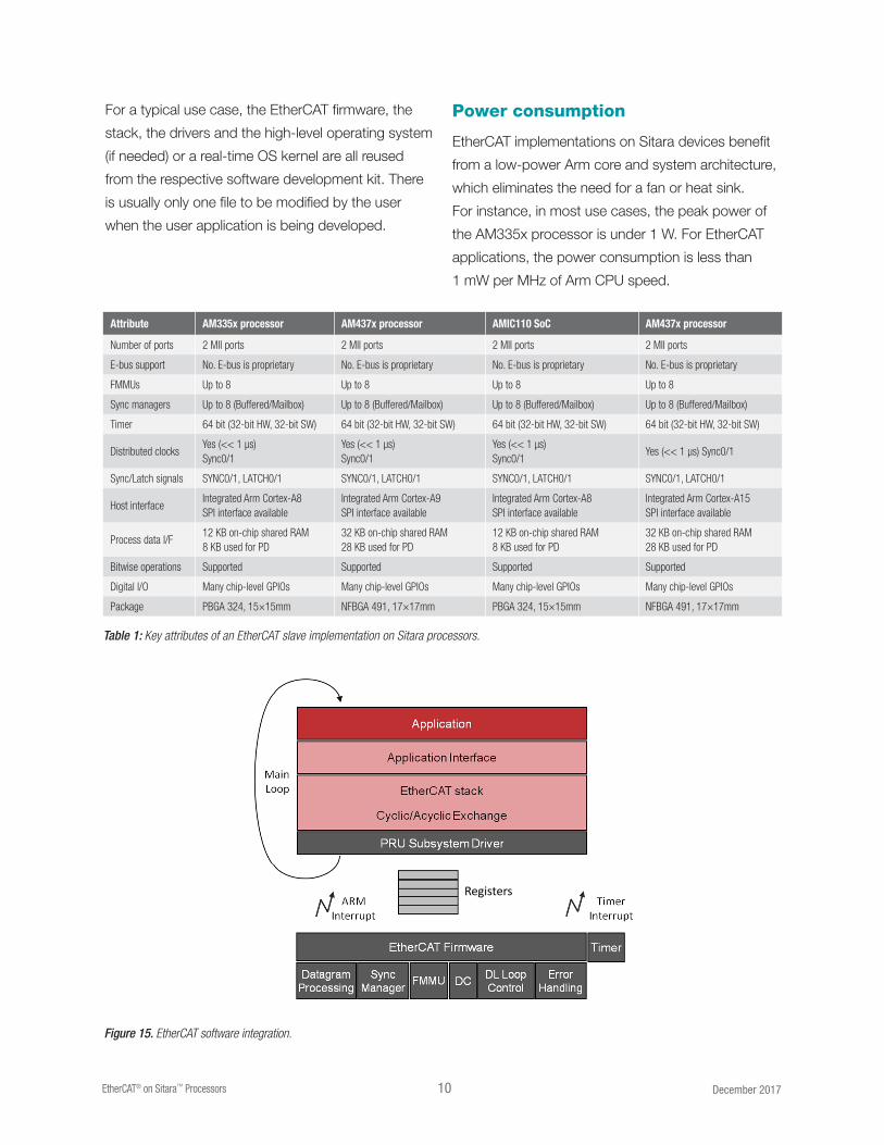
Key EtherCAT parameters
The key attributes of an EtherCAT slave implementa-
tion on the Sitara AM335x and AM437x processors
are provided in Table 1.
Easy EtherCAT integration
TI has streamlined the process of integrating
EtherCAT with the Sitara processors. All the tools and
software code required to integrate EtherCAT slaves
are available as part of these processors’ software
development kits (SDK). On each development
platform, the SDK includes firmware for the Ether-
CAT protocol, software drivers, hardware initialization
routines, adaptation layer for the stack API, EtherCAT
protocol stack and the application itself. The
supporting documentation with the SDK enables one
to modify and build new features into the application.
To facilitate the integration of the EtherCAT protocol
stack, TI has also closely collaborated with Beckhoff
Automation to validate EtherCAT Slave Stack Code on
the Sitara processors. The Beckhoff code has been
adapted to work on the Sitara processors and it has
been tested to ensure that the integration is seamless
for customers. Customers are expected to become
ETG members (required to market EtherCAT products)
and get entitled to obtain a free copy of the Beckhoff
stack directly via the ETG website before taking their
product to market. A copy of the EtherCAT stack from
Beckhoff is also included in the Processor SDK for
evaluation, development and test purposes.
10 EtherCAT® on Sitara™ Processors December 2017
For a typical use case, the EtherCAT firmware, the
stack, the drivers and the high-level operating system
(if needed) or a real-time OS kernel are all reused
from the respective software development kit. There
is usually only one file to be modified by the user
when the user application is being developed.
Power consumption
EtherCAT implementations on Sitara devices benefit
from a low-power Arm core and system architecture,
which eliminates the need for a fan or heat sink.
For instance, in most use cases, the peak power of
the AM335x processor is under 1 W. For EtherCAT
applications, the power consumption is less than
1 mW per MHz of Arm CPU speed.
Attribute AM335x processor AM437x processor AMIC110 SoC AM437x processor
Number of ports 2 MII ports 2 MII ports 2 MII ports 2 MII ports
E-bus support No. E-bus is proprietary No. E-bus is proprietary No. E-bus is proprietary No. E-bus is proprietary
FMMUs Up to 8 Up to 8 Up to 8 Up to 8
Sync managers Up to 8 (Buffered/Mailbox) Up to 8 (Buffered/Mailbox) Up to 8 (Buffered/Mailbox) Up to 8 (Buffered/Mailbox)
Timer 64 bit (32-bit HW, 32-bit SW) 64 bit (32-bit HW, 32-bit SW) 64 bit (32-bit HW, 32-bit SW) 64 bit (32-bit HW, 32-bit SW)
Distributed clocksYes (<< 1 µs)Sync0/1
Yes (<< 1 µs)Sync0/1
Yes (<< 1 µs)Sync0/1
Yes (<< 1 µs) Sync0/1
Sync/Latch signals SYNC0/1, LATCH0/1 SYNC0/1, LATCH0/1 SYNC0/1, LATCH0/1 SYNC0/1, LATCH0/1
Host interfaceIntegrated Arm Cortex-A8SPI interface available
Integrated Arm Cortex-A9SPI interface available
Integrated Arm Cortex-A8SPI interface available
Integrated Arm Cortex-A15 SPI interface available
Process data I/F12 KB on-chip shared RAM8 KB used for PD
32 KB on-chip shared RAM28 KB used for PD
12 KB on-chip shared RAM8 KB used for PD
32 KB on-chip shared RAM28 KB used for PD
Bitwise operations Supported Supported Supported Supported
Digital I/O Many chip-level GPIOs Many chip-level GPIOs Many chip-level GPIOs Many chip-level GPIOs
Package PBGA 324, 15×15mm NFBGA 491, 17×17mm PBGA 324, 15×15mm NFBGA 491, 17×17mm
Table 1: Key attributes of an EtherCAT slave implementation on Sitara processors.
Figure 15. EtherCAT software integration.
Registers
Integrating EtherCAT on end products
In order to integrate EtherCAT slave into industrial
equipment, customers can use TI’s EtherCAT slave
implementation and complete their design process
using the evaluation copy of the EtherCAT Slave
Stack Code provided in the Processor SDK. The
Slave Stack Code is originally obtained from Beckhoff
and it is available to all ETG members for no charge.
Customers can also use a slave stack from a different
vendor or develop their own. The customer should use
Conformance Test Tool to pass all tests. Optionally,
they can then get the product certified by EtherCAT
certification labs and may also perform broader
interoperability tests at the EtherCAT plug fests.
Devices for EtherCAT implementation
TI provides several Sitara processors for EtherCAT
implementations, as well as complementary analog
products for the signal chain and power circuitry.
A brief description of these products is provided
in Table 2 below. These products are available in
industrial grade temperature range and have long-
term availability.
Product Description
AM335x Arm® Cortex™-A8 32-bit microprocessor available in two speed grades. Integrated EtherCAT® slave/master
AM3517 Arm Cortex-A8 microprocessor for EtherCAT master applications
AM437x Arm Cortex-A9 32-bit processor available in speed grades up to 1 GHz. Integrated EtherCAT slave/master
AMIC110 Arm Cortex-A8 processor optimized for industrial communications available in 300 MHz speed grade. Integrated EtherCAT slave/master
AM57x Dual or single Arm Cortex-A15 processor available in speed grades up to 1.5 GHz. Integrated EtherCAT slave/master
DP83822 Low power Ethernet PHY optimized for connection via MII, RMII, or RGMII
TLK110 Ethernet PHY optimized for high-performance industrial Ethernet such as EtherCAT
TPS65910 Advanced low-footprint power management solution for AM335x microprocessors
Table 2: TI EtherCAT devices.
Development tools for EtherCAT implementation
TI provides Evaluation Module (EVM) development
platforms for its Sitara processors with
comprehensive design data to assist customers
with their implementations. All design data for these
EVMs such as schematics and layout is available for
accelerating development of customer designs. For
more information on the tools available for specific
processors, click here.
In addition, TI also collaborates with external vendors
for an additional development platform targeted for
industrial applications.
Summary
TI offers integrated EtherCAT slave and master capability on Sitara processors targeted for industrial I/O, sensor, PLC and human machine interface (HMI) systems. The integration of EtherCAT with a powerful yet low-power Arm core results in lower-cost end products without compromise on the functional or operational requirements. TI also offers the transceivers with built-in isolation for the industrial communication interfaces such as EtherCAT, PROFIBUS, CAN, RS-485 and more. With comprehensive software and hardware development tools, worldwide support and an active E2E™ developer community, customers can look forward to greatly simplified EtherCAT integration with the added benefit of significant cost savings – as much as 30 percent!
© 2017 Texas Instruments Incorporated SPRY187G
The platform bar and Sitara are trademarks of Texas Instruments. All other trademarks are the property of their respective owners.
Important Notice: The products and services of Texas Instruments Incorporated and its subsidiaries described herein are sold subject to TI’s standard terms and conditions of sale. Customers are advised to obtain the most current and complete information about TI products and services before placing orders. TI assumes no liability for applications assistance, customer’s applications or product designs, software performance, or infringement of patents. The publication of information regarding any other company’s products or services does not constitute TI’s approval, warranty or endorsement thereof.
IMPORTANT NOTICE FOR TI DESIGN INFORMATION AND RESOURCES
Texas Instruments Incorporated (‘TI”) technical, application or other design advice, services or information, including, but not limited to,reference designs and materials relating to evaluation modules, (collectively, “TI Resources”) are intended to assist designers who aredeveloping applications that incorporate TI products; by downloading, accessing or using any particular TI Resource in any way, you(individually or, if you are acting on behalf of a company, your company) agree to use it solely for this purpose and subject to the terms ofthis Notice.TI’s provision of TI Resources does not expand or otherwise alter TI’s applicable published warranties or warranty disclaimers for TIproducts, and no additional obligations or liabilities arise from TI providing such TI Resources. TI reserves the right to make corrections,enhancements, improvements and other changes to its TI Resources.You understand and agree that you remain responsible for using your independent analysis, evaluation and judgment in designing yourapplications and that you have full and exclusive responsibility to assure the safety of your applications and compliance of your applications(and of all TI products used in or for your applications) with all applicable regulations, laws and other applicable requirements. Yourepresent that, with respect to your applications, you have all the necessary expertise to create and implement safeguards that (1)anticipate dangerous consequences of failures, (2) monitor failures and their consequences, and (3) lessen the likelihood of failures thatmight cause harm and take appropriate actions. You agree that prior to using or distributing any applications that include TI products, youwill thoroughly test such applications and the functionality of such TI products as used in such applications. TI has not conducted anytesting other than that specifically described in the published documentation for a particular TI Resource.You are authorized to use, copy and modify any individual TI Resource only in connection with the development of applications that includethe TI product(s) identified in such TI Resource. NO OTHER LICENSE, EXPRESS OR IMPLIED, BY ESTOPPEL OR OTHERWISE TOANY OTHER TI INTELLECTUAL PROPERTY RIGHT, AND NO LICENSE TO ANY TECHNOLOGY OR INTELLECTUAL PROPERTYRIGHT OF TI OR ANY THIRD PARTY IS GRANTED HEREIN, including but not limited to any patent right, copyright, mask work right, orother intellectual property right relating to any combination, machine, or process in which TI products or services are used. Informationregarding or referencing third-party products or services does not constitute a license to use such products or services, or a warranty orendorsement thereof. Use of TI Resources may require a license from a third party under the patents or other intellectual property of thethird party, or a license from TI under the patents or other intellectual property of TI.TI RESOURCES ARE PROVIDED “AS IS” AND WITH ALL FAULTS. TI DISCLAIMS ALL OTHER WARRANTIES ORREPRESENTATIONS, EXPRESS OR IMPLIED, REGARDING TI RESOURCES OR USE THEREOF, INCLUDING BUT NOT LIMITED TOACCURACY OR COMPLETENESS, TITLE, ANY EPIDEMIC FAILURE WARRANTY AND ANY IMPLIED WARRANTIES OFMERCHANTABILITY, FITNESS FOR A PARTICULAR PURPOSE, AND NON-INFRINGEMENT OF ANY THIRD PARTY INTELLECTUALPROPERTY RIGHTS.TI SHALL NOT BE LIABLE FOR AND SHALL NOT DEFEND OR INDEMNIFY YOU AGAINST ANY CLAIM, INCLUDING BUT NOTLIMITED TO ANY INFRINGEMENT CLAIM THAT RELATES TO OR IS BASED ON ANY COMBINATION OF PRODUCTS EVEN IFDESCRIBED IN TI RESOURCES OR OTHERWISE. IN NO EVENT SHALL TI BE LIABLE FOR ANY ACTUAL, DIRECT, SPECIAL,COLLATERAL, INDIRECT, PUNITIVE, INCIDENTAL, CONSEQUENTIAL OR EXEMPLARY DAMAGES IN CONNECTION WITH ORARISING OUT OF TI RESOURCES OR USE THEREOF, AND REGARDLESS OF WHETHER TI HAS BEEN ADVISED OF THEPOSSIBILITY OF SUCH DAMAGES.You agree to fully indemnify TI and its representatives against any damages, costs, losses, and/or liabilities arising out of your non-compliance with the terms and provisions of this Notice.This Notice applies to TI Resources. Additional terms apply to the use and purchase of certain types of materials, TI products and services.These include; without limitation, TI’s standard terms for semiconductor products http://www.ti.com/sc/docs/stdterms.htm), evaluationmodules, and samples (http://www.ti.com/sc/docs/sampterms.htm).
Mailing Address: Texas Instruments, Post Office Box 655303, Dallas, Texas 75265Copyright © 2017, Texas Instruments Incorporated