Embed Size (px)
Citation preview
AMIC110
Arm®
Cortex®-A8
Connectivity
PRU_ICSS GPMC
SPII2C
CANUART
McASP
Flash
DDR
Power Management
UART
Industrial EPHY
Industrial EPHY
1TIDUE46–February 2018Submit Documentation Feedback
Copyright © 2018, Texas Instruments Incorporated
DDR-less EtherCAT® Slave on AMIC110 Reference Design
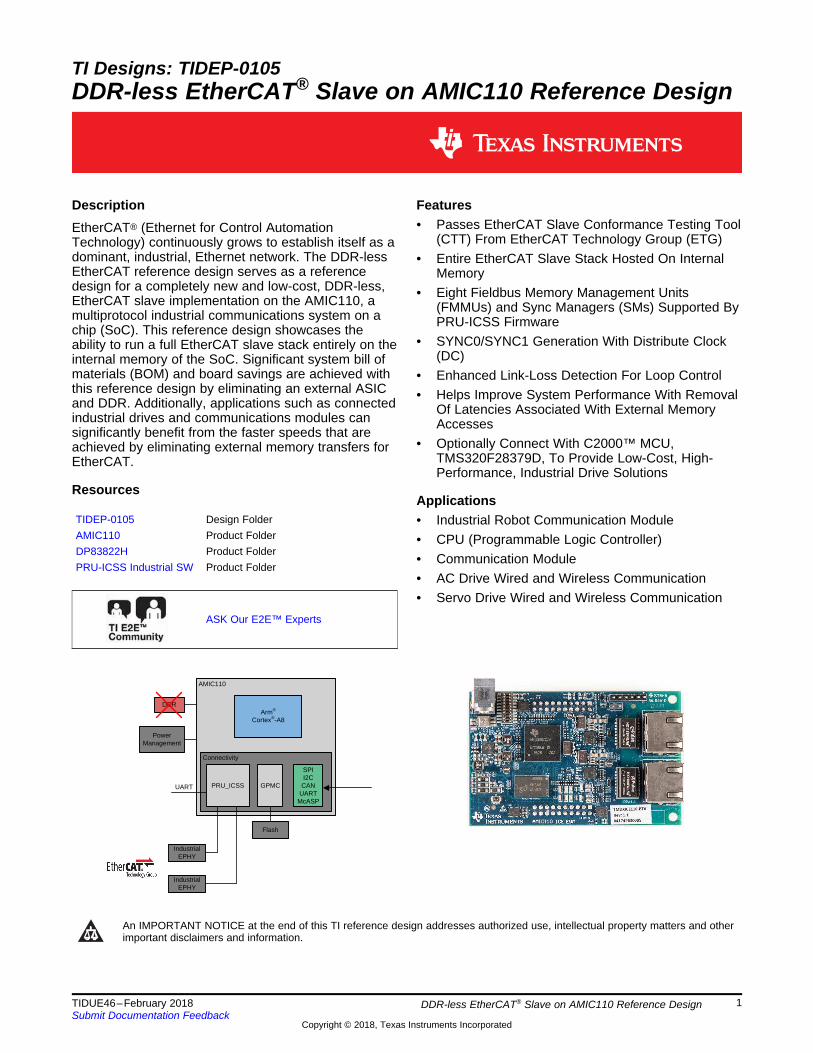
TI Designs: TIDEP-0105DDR-less EtherCAT® Slave on AMIC110 Reference Design
DescriptionEtherCAT® (Ethernet for Control AutomationTechnology) continuously grows to establish itself as adominant, industrial, Ethernet network. The DDR-lessEtherCAT reference design serves as a referencedesign for a completely new and low-cost, DDR-less,EtherCAT slave implementation on the AMIC110, amultiprotocol industrial communications system on achip (SoC). This reference design showcases theability to run a full EtherCAT slave stack entirely on theinternal memory of the SoC. Significant system bill ofmaterials (BOM) and board savings are achieved withthis reference design by eliminating an external ASICand DDR. Additionally, applications such as connectedindustrial drives and communications modules cansignificantly benefit from the faster speeds that areachieved by eliminating external memory transfers forEtherCAT.
Resources
TIDEP-0105 Design FolderAMIC110 Product FolderDP83822H Product FolderPRU-ICSS Industrial SW Product Folder
ASK Our E2E™ Experts
Features• Passes EtherCAT Slave Conformance Testing Tool
(CTT) From EtherCAT Technology Group (ETG)• Entire EtherCAT Slave Stack Hosted On Internal
Memory• Eight Fieldbus Memory Management Units
(FMMUs) and Sync Managers (SMs) Supported ByPRU-ICSS Firmware
• SYNC0/SYNC1 Generation With Distribute Clock(DC)
• Enhanced Link-Loss Detection For Loop Control• Helps Improve System Performance With Removal
Of Latencies Associated With External MemoryAccesses
• Optionally Connect With C2000™ MCU,TMS320F28379D, To Provide Low-Cost, High-Performance, Industrial Drive Solutions
Applications• Industrial Robot Communication Module• CPU (Programmable Logic Controller)• Communication Module• AC Drive Wired and Wireless Communication• Servo Drive Wired and Wireless Communication
An IMPORTANT NOTICE at the end of this TI reference design addresses authorized use, intellectual property matters and otherimportant disclaimers and information.

System Description www.ti.com
2 TIDUE46–February 2018Submit Documentation Feedback
Copyright © 2018, Texas Instruments Incorporated
DDR-less EtherCAT® Slave on AMIC110 Reference Design
1 System DescriptionEtherCAT, invented by Beckhoff Automation in Germany and later standardized by the ETG, is a real-time, industrial, Ethernet standard for industrial automation applications, such as input/output (I/O)devices, communication modules, sensors, and programmable logic controllers (PLCs).
Traditional Ethernet has seen unparalleled adoption in diverse applications, but in industrial environmentsit is still not efficient enough for small amounts of data exchange, due to its lower determinism for real-timeoperation and also works in which the network nodes must be connected through switches. EtherCATimproves upon traditional Ethernet by implementing on-the-fly processing, where the nodes in theEtherCAT network read the data from a frame as it passes through. All EtherCAT frames originate fromthe EtherCAT master, which sends commands and data to the slaves. Any data to be sent back to themaster is written by the slave onto the frame as it passes through.
Many simple EtherCAT devices such as digital I/Os can be created using single FPGA or ASIC solutionsavailable today. In EtherCAT nodes where additional processing power is needed, an external processor,often with on-chip Flash memory, is connected to the EtherCAT ASIC/FPGA for handling application-levelprocessing. The cost of such architecture is higher than that of simple digital I/O devices, but it comes withflexibility in that developers can select a processor that suits their needs. In yet another approach, theEtherCAT implementation is one of the peripherals in the device that has an integrated CPU. Many FPGAdevices can configure a processor in the FPGA or already have an integrated processor. The FPGAs areflexible, but depending on the CPU selection there is a risk that costs or operating frequency targets willbe challenging to meet.
To meet the demand of cost-sensitive, industrial automation applications, this TI Design presents areference design for a completely new, compact implementation that provides a low-cost, DDR-less,EtherCAT Slave with the AMIC110, a multiprotocol programmable industrial communications SoC.Significant system BOM and board savings are achieved with the solution by eliminating an external ASICand DDR. In addition, the software- and firmware-based architecture and the PRU-ICSS IndustrialCommunications suite can scale to support multiple industrial Ethernet and fieldbus communicationstandards.
1.1 Key System Specifications
Table 1. Key System Specifications
PARAMETER SPECIFICATIONS DETAILS
EtherCAT commands NOP, ARPD, APWR, APRW, FPRD, FPWR, FPRW, BRD,BWR, BRW, LRD, LWR, LRW, ARMW and FRMW All supported
Number of ports 2 MII ports Connection between the PHY(DP83822) and MAC (AMIC110)
Number of FMMUs and SMs Up to 8 Fieldbus memory management unitand sync managers
Process data RAM 8KB From PRU shared RAM
Distributed clock Yes Supports SYNC0, SYNC1,LATCH0 and LATCH1 signals
Conformance test Pass Section 3.2.2.2
AMIC110
Proc SDK
Industrial Application
API
Protocol Stack
API
Protocol Driver
Protocol Firmware
SPI Master I/F to Customer HW
SPI API
Ethernet PHYSPI
Customer Drive or Data Acquisition System
(for example, C2000�)
TI-RTOS
Bootloader
Tools
Periph Drivers
Application
Data Link
PhysicalBeckhoff, other thirdparty or Customer
TI Source
TI Binary
TI Example andCustomer application
ARM
PRUSS
www.ti.com System Overview
3TIDUE46–February 2018Submit Documentation Feedback
Copyright © 2018, Texas Instruments Incorporated
DDR-less EtherCAT® Slave on AMIC110 Reference Design
2 System Overview
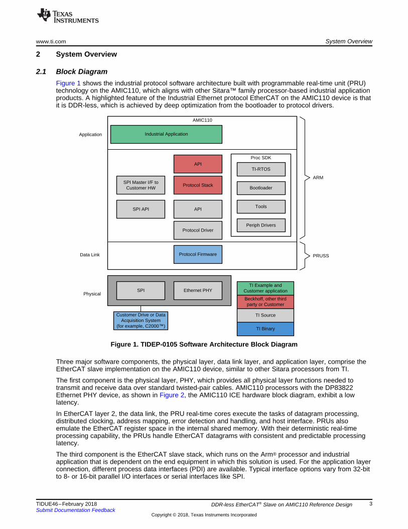
2.1 Block DiagramFigure 1 shows the industrial protocol software architecture built with programmable real-time unit (PRU)technology on the AMIC110, which aligns with other Sitara™ family processor-based industrial applicationproducts. A highlighted feature of the Industrial Ethernet protocol EtherCAT on the AMIC110 device is thatit is DDR-less, which is achieved by deep optimization from the bootloader to protocol drivers.
Figure 1. TIDEP-0105 Software Architecture Block Diagram
Three major software components, the physical layer, data link layer, and application layer, comprise theEtherCAT slave implementation on the AMIC110 device, similar to other Sitara processors from TI.
The first component is the physical layer, PHY, which provides all physical layer functions needed totransmit and receive data over standard twisted-pair cables. AMIC110 processors with the DP83822Ethernet PHY device, as shown in Figure 2, the AMIC110 ICE hardware block diagram, exhibit a lowlatency.
In EtherCAT layer 2, the data link, the PRU real-time cores execute the tasks of datagram processing,distributed clocking, address mapping, error detection and handling, and host interface. PRUs alsoemulate the EtherCAT register space in the internal shared memory. With their deterministic real-timeprocessing capability, the PRUs handle EtherCAT datagrams with consistent and predictable processinglatency.
The third component is the EtherCAT slave stack, which runs on the Arm® processor and industrialapplication that is dependent on the end equipment in which this solution is used. For the application layerconnection, different process data interfaces (PDI) are available. Typical interface options vary from 32-bitto 8- or 16-bit parallel I/O interfaces or serial interfaces like SPI.
SPI_D1_McASP1_FSX_MFSRB
Input 5 V DC jack
3.3-V TTL,fail-save I/O
JTAG HDR
SPI Flash
DDR3 EEPROM
Board ID
10/100 Mb/sEthernet PHY1
DP83822
AMIC110
SPI JTAG UART0 Status LEDs
Magnetics RJ45
10/100 Mb/sEthernet PHY2
DP83822
Status LEDs
Magnetics RJ45
Status LED perEtherCAT® standard
requirements
UART1_TXUART1_RXUART1_DE
PR
OF
IBU
S®
ECAT_LATCH0ECAT_LATCH1ECAT_SYNC0ECAT_SYNC1IRQFirmware_LoadedSYS_RESETn
EC
AT
&S
ys
McASP1_AXR0_MDRBMcASP1_AXR1_MDRBMcASP1_ACLKR_MCLKXBMcASP1_ACLKX_MCLKXBMcASP1_FSR_MFSXB
MC
AS
P
SPICLKSPI_D1SPICSSPI_D0
SP
I
6-pin headerfor 3.3-V TTLserial-to-USB
cable
PMICTPS650250
EMI filter
HDR3V33V3
1V81V51V1
I/O c
onne
ctor
s
C2000�MCUwithEtherCAT®
stack anddriver forET1100
Fai
l-sav
e I/O
(3.
3 V
)
System Overview www.ti.com
4 TIDUE46–February 2018Submit Documentation Feedback
Copyright © 2018, Texas Instruments Incorporated
DDR-less EtherCAT® Slave on AMIC110 Reference Design
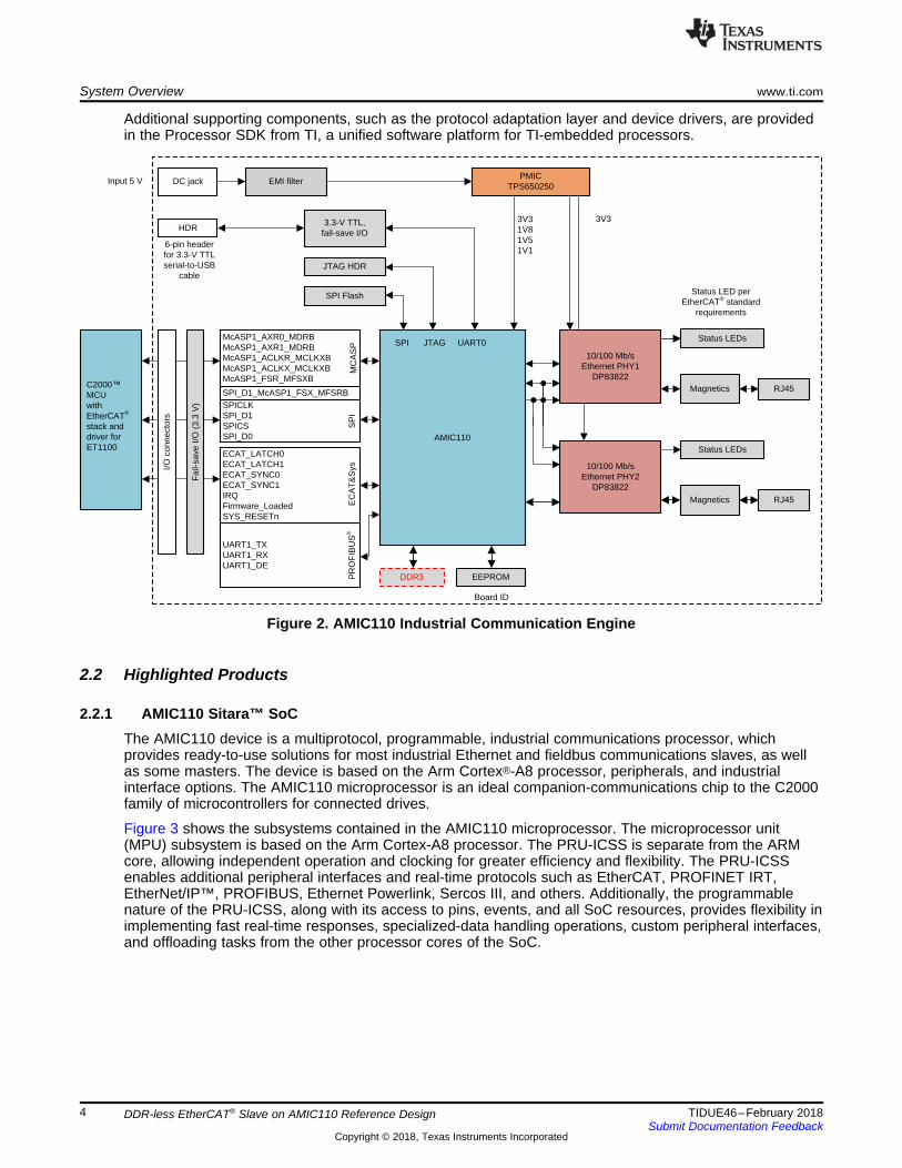
Additional supporting components, such as the protocol adaptation layer and device drivers, are providedin the Processor SDK from TI, a unified software platform for TI-embedded processors.
Figure 2. AMIC110 Industrial Communication Engine
2.2 Highlighted Products
2.2.1 AMIC110 Sitara™ SoCThe AMIC110 device is a multiprotocol, programmable, industrial communications processor, whichprovides ready-to-use solutions for most industrial Ethernet and fieldbus communications slaves, as wellas some masters. The device is based on the Arm Cortex®-A8 processor, peripherals, and industrialinterface options. The AMIC110 microprocessor is an ideal companion-communications chip to the C2000family of microcontrollers for connected drives.
Figure 3 shows the subsystems contained in the AMIC110 microprocessor. The microprocessor unit(MPU) subsystem is based on the Arm Cortex-A8 processor. The PRU-ICSS is separate from the ARMcore, allowing independent operation and clocking for greater efficiency and flexibility. The PRU-ICSSenables additional peripheral interfaces and real-time protocols such as EtherCAT, PROFINET IRT,EtherNet/IP™, PROFIBUS, Ethernet Powerlink, Sercos III, and others. Additionally, the programmablenature of the PRU-ICSS, along with its access to pins, events, and all SoC resources, provides flexibility inimplementing fast real-time responses, specialized-data handling operations, custom peripheral interfaces,and offloading tasks from the other processor cores of the SoC.

45nm
PRU_ICSS
Industrial Communication Subsystem
EtherCAT®, PROFINET®, EtherNET/IPTM,
PROFIBUS, HSR/PRP, and more
256 K L2 w/ECC
64K RAM
64KB L3 Shared RAM
LODDR1/DDR2/DDR3/DDR3L
Arm® Cortex®-A8300 MHz
32K/32K L1
EDMA JTAG/ETB Timers x8 WDT RTC12-bit ADC(1)
System Services
AMIC110
Connectivity and IOs
USB2OTG
+PHY x2CAN x2
PWM x3
SPI x2
I2C
McASP x2
GPIO
UART x6
GPMc/NAND/NOR(16bit ECC)
MMC/SD/SDIO x3
www.ti.com System Overview
5TIDUE46–February 2018Submit Documentation Feedback
Copyright © 2018, Texas Instruments Incorporated
DDR-less EtherCAT® Slave on AMIC110 Reference Design
Figure 3 shows the AMIC110 microprocessor functional block diagram.
Figure 3. AMIC110 Microprocessor Functional Block Diagram
Key features:• Up to 300-MHz Sitara, ARM Cortex-A8, 32‑bit RISC processor:
– NEON™ single instruction multiple data (SIMD) coprocessor– 32KB of L1 instruction and 32KB of data cache with single-error detection (parity)– 256KB of L2 cache with error correcting code (ECC)– 176KB of on-chip boot ROM– 64KB of dedicated RAM– Interrupt controller (up to 128 interrupt requests)
• On-chip memory (shared L3 RAM):– 64KB of general-purpose, on-chip memory controller (OCMC) RAM– Accessible to all masters
• Industrial communication subsystem (PRU-ICSS):– Supports protocols such as EtherCAT, PROFIBUS, PROFINET, EtherNet/IP, and more– Two PRUs– 32-bit load/store RISC processor, capable of running at 200 MHz– 8KB of instruction RAM with single-error detection (parity)– Single-cycle, 32-bit multiplier with 64-bit accumulator– Enhanced GPIO module provides shift-in/out support and parallel latch on the external signal
Status LEDs
25-MHz / 50-MHzClock Source
DP8382210/100 MbpsEthernet PHY
MAC
MIIRMII
RGMII
Capacitors
Magnetics
Fiber Optic Transceiver
RJ-45
100BASE-Te100BASE-TX
100BASE-FX
System Overview www.ti.com
6 TIDUE46–February 2018Submit Documentation Feedback
Copyright © 2018, Texas Instruments Incorporated
DDR-less EtherCAT® Slave on AMIC110 Reference Design
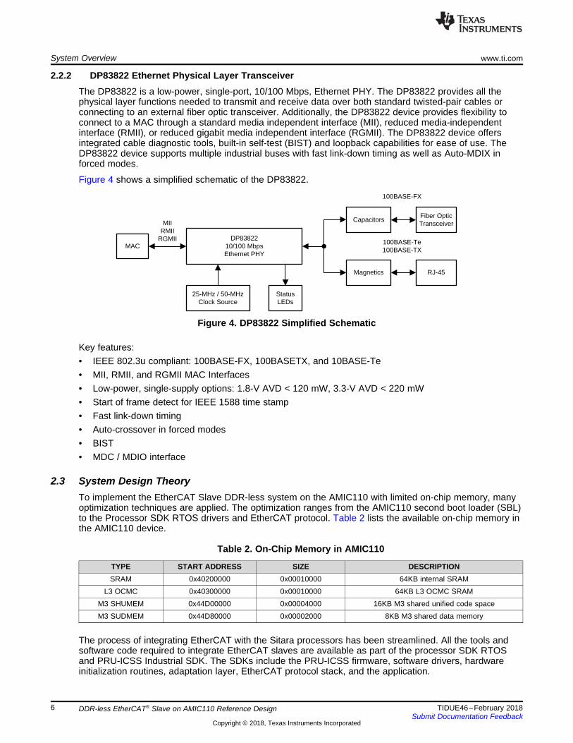
2.2.2 DP83822 Ethernet Physical Layer TransceiverThe DP83822 is a low-power, single-port, 10/100 Mbps, Ethernet PHY. The DP83822 provides all thephysical layer functions needed to transmit and receive data over both standard twisted-pair cables orconnecting to an external fiber optic transceiver. Additionally, the DP83822 device provides flexibility toconnect to a MAC through a standard media independent interface (MII), reduced media-independentinterface (RMII), or reduced gigabit media independent interface (RGMII). The DP83822 device offersintegrated cable diagnostic tools, built-in self-test (BIST) and loopback capabilities for ease of use. TheDP83822 device supports multiple industrial buses with fast link-down timing as well as Auto-MDIX inforced modes.
Figure 4 shows a simplified schematic of the DP83822.
Figure 4. DP83822 Simplified Schematic
Key features:• IEEE 802.3u compliant: 100BASE-FX, 100BASETX, and 10BASE-Te• MII, RMII, and RGMII MAC Interfaces• Low-power, single-supply options: 1.8-V AVD < 120 mW, 3.3-V AVD < 220 mW• Start of frame detect for IEEE 1588 time stamp• Fast link-down timing• Auto-crossover in forced modes• BIST• MDC / MDIO interface
2.3 System Design TheoryTo implement the EtherCAT Slave DDR-less system on the AMIC110 with limited on-chip memory, manyoptimization techniques are applied. The optimization ranges from the AMIC110 second boot loader (SBL)to the Processor SDK RTOS drivers and EtherCAT protocol. Table 2 lists the available on-chip memory inthe AMIC110 device.
Table 2. On-Chip Memory in AMIC110
TYPE START ADDRESS SIZE DESCRIPTIONSRAM 0x40200000 0x00010000 64KB internal SRAM
L3 OCMC 0x40300000 0x00010000 64KB L3 OCMC SRAMM3 SHUMEM 0x44D00000 0x00004000 16KB M3 shared unified code spaceM3 SUDMEM 0x44D80000 0x00002000 8KB M3 shared data memory
The process of integrating EtherCAT with the Sitara processors has been streamlined. All the tools andsoftware code required to integrate EtherCAT slaves are available as part of the processor SDK RTOSand PRU-ICSS Industrial SDK. The SDKs include the PRU-ICSS firmware, software drivers, hardwareinitialization routines, adaptation layer, EtherCAT protocol stack, and the application.
www.ti.com System Overview
7TIDUE46–February 2018Submit Documentation Feedback
Copyright © 2018, Texas Instruments Incorporated
DDR-less EtherCAT® Slave on AMIC110 Reference Design
2.3.1 SBL OptimizationThe SBL sets up the PLL clocks, powers on the I/O Peripherals, initializes the DDR, loads the applicationimage into DDR, and brings the slave cores out of reset for applicable SoCs. A variety of boot modes suchas QSPI, UART, MMCSD, NAND, and MCSPI are available in typical Sitara devices. The SBL uses part ofthe internal memory that has to be reduced to allow the EtherCAT stack and application to fit in.
2.3.1.1 Reducing SBL SizeEarlier versions of the AM335x/AMIC110 SBL in the Processor SDK RTOS for MCSPI boot mode: 34KB(release) and 57KB (debug).
The following changes have been implemented to reduce the size of the SBL for this use case:• Bypass or remove SBL code and data for DDR setup• Remove board and SoC detect functions to make the SBL specific for the AMIC110• Remove console utilities to allow direct application boot
Implementation:• Setup using the build option USE_DDR to configure the DDRLESS option in the source code• Implementation generates cut-down version of board, utilities, device and bootloader components
2.3.1.2 Wakeup PRUThe EtherCAT application contains two, 8KB, constant arrays which contain the PRU firmware that getscopied into the OCMC memory and gets copied into the PRU IRAM memory. To avoid the copy, amechanism was implemented in the SBL to load the application from the flash to PRU0 and PRU1 IRAM,which also avoids use of an additional 16KB of memory in the OCMC. To load the PRU0 and PRU1IRAMs, the Arm needs to enable the PRU using PRCM.
Implementation:• Setup build option ENABLE_PRU to perform the PRU wake-up sequence in the bootloader code.• The option wakes up PRU0 and PRU1 and with flush data RAM
2.3.1.3 Storing and Loading Copy of TIESC EEPROM Data and PRU IRAM BinariesThe EtherCAT application has a requirement to save TIESC EEPROM data in nonvolatile memory thatcan be used to restore the setup. This data is also stored as a constant in the application and copied, tobe used by the EtherCAT application during normal operation. This data was moved to the SPI flash andloaded in by the bootloader for the application to consume.
Implementation:• Put binary images into TI Image format and load them based on the configuration file that specifies the
number of binaries to load and the offset from which they are read into the device memory.• Customization allows for loading of PRU firmware in IRAM and DATA RAM and also additional
industrial constant arrays, like TIESC, into device memory

FrameProc( )
hostProc( )
PRU IRAM
0x4a334000 8KB ± PRU00x4a334000 8KB ± PRU1
.stack
free (4KB)
M3SHDMEM
0x44d80000 4KB0x44d90000 4KB
MMU table
M3SHUMEM
0x44d00000 16KB
.bss
SRAM + OCMC
0x402f0400 20KB
.text
«...
0x402f5400
107KB
.ARM.exidx
.data
free (16KB)
tiesc_eeprom( )0x403F0400 3KB
MLO
tiesc_eeprom( )
0
0x10000
FrameProc( )
hostProc( )
app
McSPI Flash
0x14000
0x19000
0x20000
bootloader
System Overview www.ti.com
8 TIDUE46–February 2018Submit Documentation Feedback
Copyright © 2018, Texas Instruments Incorporated
DDR-less EtherCAT® Slave on AMIC110 Reference Design
Figure 5 shows the SBL and EtherCAT memory map on the AMIC110 device. The .bss section of theEtherCAT application is designed to overlap with the SBL for maximum use of on-chip memory, becausethe .bss section is loaded only after the SBL has loaded the application and exited.
Figure 5. SBL and EtherCAT® Memory Map on AMIC110
2.3.2 Host Driver and Protocol Optimization
2.3.2.1 Memory Use AnalysisUsing the object dump tool (arm-none-eabi-objdump.exe) from Arm GCC, the memory sections of theEtherCAT slave can be retrieved from the executable ARM binary (see Table 3).
Table 3. Memory Sections From Arm® GCC Compiler
LOADED SECTION UNLOADED SECTION.c_int00 .comment
ti.sysbios.family.arm.a8.mmuTableSection .ARM.attributesxdc.meta .debug_aranges
.text .debug_info.rodata .debug_abbrev.vectors .debug_line
.ARM.exidx .debug_frame.data .debug_str.bss .debug_loc
.stack .debug_ranges
These sections can be categorized into two types during code execution – loaded and unloaded. Theloaded sections are the areas being investigated.
www.ti.com System Overview
9TIDUE46–February 2018Submit Documentation Feedback
Copyright © 2018, Texas Instruments Incorporated
DDR-less EtherCAT® Slave on AMIC110 Reference Design
2.3.2.2 Optimization TechniquesA number of techniques were used to reduce the EtherCAT application fit into the AMIC110 on-chipmemory.1. The first step is to eliminate code support for unused features of the device, the ICE board, and in TI-
RTOS. For example, in this application the I2C interface, SPI write, and the UART/ text/ printf supportcould be eliminated in both the application and in RTOS.
2. The next step is to minimize the RTOS debug and error handing components to what is necessary forthe runtime application. Here, the error handlers and exception stack size are reduced, andunnecessary functions such as RTOS logging, RTS Thread protection, and stack overrun checking areeliminated.
3. The third step is to eliminate any unnecessary operations and optimize the remaining functions. Forexample, because the application runs only on a dedicated hardware configuration, the deviceconfiguration is static and does not need to be read from an EEPROM. Reduce functionalrepresentations to an optimum size. This reduction can be done by using bit arrays in place of wordarrays. Optimize SYSBIOS to use a custom code configuration of just the necessary components.Evaluate the Stack and Heap use and set their reserved sizes to optimum values.
4. The last step is to compile the code and link the code with the appropriate settings to minimize theexecutable size and pack the executable into the available memory regions. These optimizationsfollow:
• Use Thumb mode.• Optimize for size -Os.• Use NEON and hardware floating point.• Place each function in its own section.• Place data items in their own sections.• Disable all debugging information.• Enable global GNU optimizations, -flto, -fuse-linker-plugin.• Separate portions of the program and data to achieve good memory use.• Partition each relatively self-contained code block into sections, because external section references
require additional program memory and cycles.
Hardware, Software, Testing Requirements, and Test Results www.ti.com
10 TIDUE46–February 2018Submit Documentation Feedback
Copyright © 2018, Texas Instruments Incorporated
DDR-less EtherCAT® Slave on AMIC110 Reference Design
3 Hardware, Software, Testing Requirements, and Test Results
3.1 Required Hardware and Software
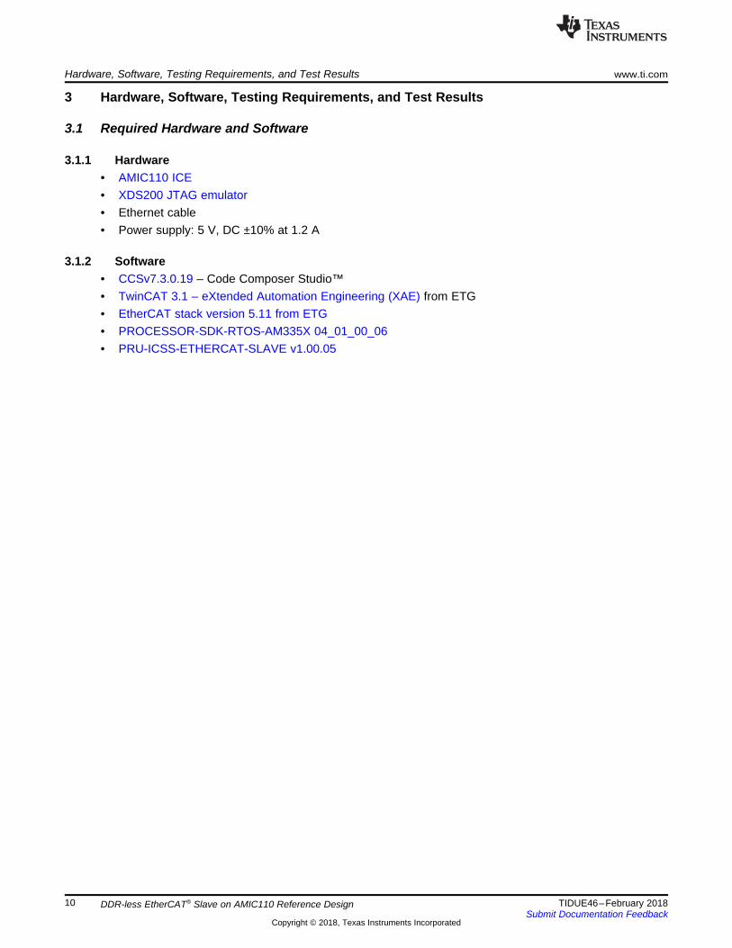
3.1.1 Hardware• AMIC110 ICE• XDS200 JTAG emulator• Ethernet cable• Power supply: 5 V, DC ±10% at 1.2 A
3.1.2 Software• CCSv7.3.0.19 – Code Composer Studio™• TwinCAT 3.1 – eXtended Automation Engineering (XAE) from ETG• EtherCAT stack version 5.11 from ETG• PROCESSOR-SDK-RTOS-AM335X 04_01_00_06• PRU-ICSS-ETHERCAT-SLAVE v1.00.05
www.ti.com Hardware, Software, Testing Requirements, and Test Results
11TIDUE46–February 2018Submit Documentation Feedback
Copyright © 2018, Texas Instruments Incorporated
DDR-less EtherCAT® Slave on AMIC110 Reference Design
3.2 Testing and Results
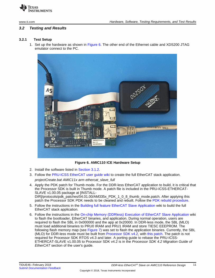
3.2.1 Test Setup1. Set up the hardware as shown in Figure 6. The other end of the Ethernet cable and XDS200 JTAG
emulator connect to the PC.
Figure 6. AMIC110 ICE Hardware Setup
2. Install the software listed in Section 3.1.2.3. Follow the PRU-ICSS EtherCAT user guide wiki to create the full EtherCAT stack application.
projectCreate.bat AMIC11x arm ethercat_slave_full4. Apply the PDK patch for Thumb mode. For the DDR-less EtherCAT application to build, it is critical that
the Processor SDK is built in Thumb mode. A patch file is included in the PRU-ICSS-ETHERCAT-SLAVE v1.00.05 package at [INSTALL-DIR]/protocols/pdk_patches/04.01.00/AM335x_PDK_1_0_8_thumb_mode.patch. After applying thispatch the Processor SDK PDK needs to be cleaned and rebuilt. Follow the PDK rebuild procedure.
5. Follow the instructions in the Building full feature EtherCAT Slave Application wiki to build the fullEtherCAT stack application.
6. Follow the instructions in the On-chip Memory (DDRless) Execution of EtherCAT Slave Application wikito flash the bootloader, EtherCAT binaries, and application. During normal operation, users arerequired to flash the SBL in 0x000000 and the app at 0x20000. In DDR-less mode, the SBL (MLO)must load additional binaries to PRU0 IRAM and PRU1 IRAM and store TIESC EEEPROM. Thefollowing flash memory map (see Figure 7) was set to flash the application binaries. Currently, the SBL(MLO) for DDR-less mode must be built from Processor SDK v4.2, with this patch. The patch is notrequired for Processor SDK RTOS v4.3 and later. A porting guide to rebase the PRU-ICSS-ETHERCAT-SLAVE v1.00.05 to Processor SDK v4.2 is in the Processor SDK 4.2 Migration Guide ofEtherCAT section of the user's guide.

MLO
tiesc_eeprom (2K)
ecat_host_interface (8K)
ecat_frame_handler (8K)
app
0x00000
0x10000
0x14000
0x19000
0x20000
Hardware, Software, Testing Requirements, and Test Results www.ti.com
12 TIDUE46–February 2018Submit Documentation Feedback
Copyright © 2018, Texas Instruments Incorporated
DDR-less EtherCAT® Slave on AMIC110 Reference Design
Figure 7. Flash Memory Map
7. Reboot the AMIC110 ICE after the binaries are flashed to the SPI flash memory.
3.2.2 Test Results
3.2.2.1 Detect DDR-Less EtherCAT® Slave Device With TwinCATFollow these instructions to set up the TwinCAT.1. Launch the TwinCAT and create a new project, for example iceAMIC110, as shown in Figure 8.
Figure 8. New Project in TwinCAT
www.ti.com Hardware, Software, Testing Requirements, and Test Results
13TIDUE46–February 2018Submit Documentation Feedback
Copyright © 2018, Texas Instruments Incorporated
DDR-less EtherCAT® Slave on AMIC110 Reference Design
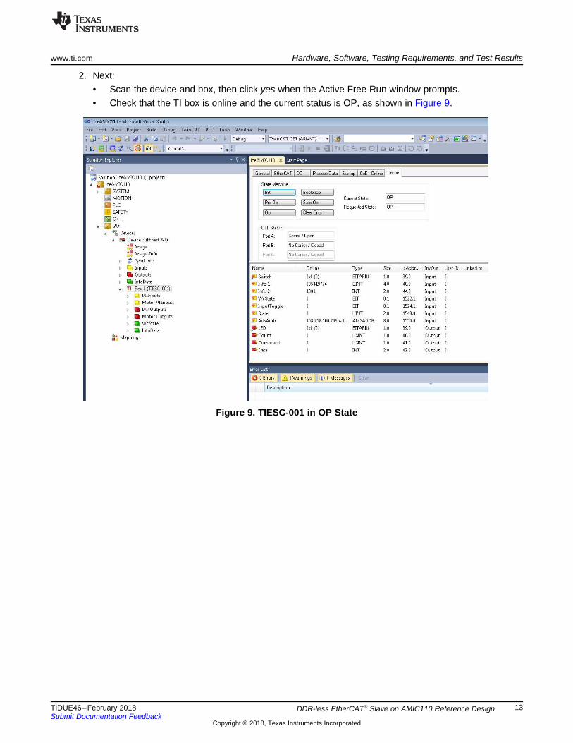
2. Next:• Scan the device and box, then click yes when the Active Free Run window prompts.• Check that the TI box is online and the current status is OP, as shown in Figure 9.
Figure 9. TIESC-001 in OP State

Hardware, Software, Testing Requirements, and Test Results www.ti.com
14 TIDUE46–February 2018Submit Documentation Feedback
Copyright © 2018, Texas Instruments Incorporated
DDR-less EtherCAT® Slave on AMIC110 Reference Design
3.2.2.2 Conformance TestThe DDR-less EtherCAT slave on the AMIC110 device successfully passes the CTT from ETG. Figure 10and Figure 11 show zero errors when using the EtherCAT device.
Figure 10. EtherCAT® Conformance Test Result
Figure 11. EtherCAT® Conformance Test Report

www.ti.com Design Files
15TIDUE46–February 2018Submit Documentation Feedback
Copyright © 2018, Texas Instruments Incorporated
DDR-less EtherCAT® Slave on AMIC110 Reference Design
4 Design Files
4.1 SchematicsTo download the schematics, see the design files at TIDEP-0105.
4.2 Bill of MaterialsTo download the bill of materials (BOM), see the design files at TIDEP-0105.
4.3 PCB Layout Recommendations
4.3.1 Layout PrintsTo download the layer plots, see the design files at TIDEP-0105.
4.4 Altium ProjectTo download the Altium project files, see the design files at TIDEP-0105.
4.5 Gerber FilesTo download the Gerber files, see the design files at TIDEP-0105.
4.6 Assembly DrawingsTo download the assembly drawings, see the design files at TIDEP-0105.
5 Software FilesTo download the software files, see the design files at TIDEP-0105.
6 Related Documentation
1. Texas Instruments, EtherCAT® on Sitara™ Processors Marketing White Paper2. Texas Instruments, EtherCAT® Slave and Multi-Protocol Industrial Ethernet Reference Design3. Texas Instruments, AM335x and AMIC110 Sitara™ Processors Technical Reference Manual4. Texas Instruments, DP83822 Robust, Low Power 10/100 Mbps Ethernet Physical Layer Transceiver
Data Sheet
6.1 TrademarksE2E, C2000, Sitara, Code Composer Studio are trademarks of Texas Instruments.NEON is a trademark of Arm Limited (or its subsidiaries).Arm, Cortex are registered trademarks of Arm Limited (or its subsidiaries).EtherCAT is a registered trademark of Beckhoff Automation GmbH.EtherNet/IP is a trademark of ODVA, Inc.All other trademarks are the property of their respective owners.
About the Authors www.ti.com
16 TIDUE46–February 2018Submit Documentation Feedback
Copyright © 2018, Texas Instruments Incorporated
DDR-less EtherCAT® Slave on AMIC110 Reference Design
7 About the AuthorsGARRETT DING is a software applications engineer for the Embedded Processing Group at TexasInstruments, where he is responsible for developing reference design solutions and providing technicalsupport to customers for the industrial segment. Garrett earned his master of science in electricalengineering (MSEE) from NanJing University of Science and Technology, China.
MANMOHAN MANDHANA is a software engineer for the Embedded Processing Group at TexasInstruments, where he is responsible for developing Industrial Communication/Fieldbus and Controlprotocols using PRU-ICSS technology available in the Embedded Processor Sitara and Keystone productlines. Manmohan earned his bachelor of technology in electrical engineering from the Indian Institute ofTechnology Bombay, India.
DAVID ZAUCHA is an applications engineer at Texas Instruments, where he is responsible for supportingcustomer applications in the Industrial Communications segment. David has been with TI since 1999 andhas been involved in designing and supporting products in analog and embedded systems. David earnedhis bachelor of science (BSEE) at the University of Massachusetts and his MSEE at the University ofRochester.
RAHUL PRABHU is a software applications engineer for the Embedded Processing Group at TexasInstruments, where he is responsible for supporting customer applications using the Sitara and Keystoneproduct lines. Rahul brings to this role his extensive experience and knowledge in RTOS applicationdevelopment and system integration. Rahul earned MS in electrical and computer engineering from theUniversity of Houston.
IMPORTANT NOTICE FOR TI DESIGN INFORMATION AND RESOURCES
Texas Instruments Incorporated (‘TI”) technical, application or other design advice, services or information, including, but not limited to,reference designs and materials relating to evaluation modules, (collectively, “TI Resources”) are intended to assist designers who aredeveloping applications that incorporate TI products; by downloading, accessing or using any particular TI Resource in any way, you(individually or, if you are acting on behalf of a company, your company) agree to use it solely for this purpose and subject to the terms ofthis Notice.TI’s provision of TI Resources does not expand or otherwise alter TI’s applicable published warranties or warranty disclaimers for TIproducts, and no additional obligations or liabilities arise from TI providing such TI Resources. TI reserves the right to make corrections,enhancements, improvements and other changes to its TI Resources.You understand and agree that you remain responsible for using your independent analysis, evaluation and judgment in designing yourapplications and that you have full and exclusive responsibility to assure the safety of your applications and compliance of your applications(and of all TI products used in or for your applications) with all applicable regulations, laws and other applicable requirements. Yourepresent that, with respect to your applications, you have all the necessary expertise to create and implement safeguards that (1)anticipate dangerous consequences of failures, (2) monitor failures and their consequences, and (3) lessen the likelihood of failures thatmight cause harm and take appropriate actions. You agree that prior to using or distributing any applications that include TI products, youwill thoroughly test such applications and the functionality of such TI products as used in such applications. TI has not conducted anytesting other than that specifically described in the published documentation for a particular TI Resource.You are authorized to use, copy and modify any individual TI Resource only in connection with the development of applications that includethe TI product(s) identified in such TI Resource. NO OTHER LICENSE, EXPRESS OR IMPLIED, BY ESTOPPEL OR OTHERWISE TOANY OTHER TI INTELLECTUAL PROPERTY RIGHT, AND NO LICENSE TO ANY TECHNOLOGY OR INTELLECTUAL PROPERTYRIGHT OF TI OR ANY THIRD PARTY IS GRANTED HEREIN, including but not limited to any patent right, copyright, mask work right, orother intellectual property right relating to any combination, machine, or process in which TI products or services are used. Informationregarding or referencing third-party products or services does not constitute a license to use such products or services, or a warranty orendorsement thereof. Use of TI Resources may require a license from a third party under the patents or other intellectual property of thethird party, or a license from TI under the patents or other intellectual property of TI.TI RESOURCES ARE PROVIDED “AS IS” AND WITH ALL FAULTS. TI DISCLAIMS ALL OTHER WARRANTIES ORREPRESENTATIONS, EXPRESS OR IMPLIED, REGARDING TI RESOURCES OR USE THEREOF, INCLUDING BUT NOT LIMITED TOACCURACY OR COMPLETENESS, TITLE, ANY EPIDEMIC FAILURE WARRANTY AND ANY IMPLIED WARRANTIES OFMERCHANTABILITY, FITNESS FOR A PARTICULAR PURPOSE, AND NON-INFRINGEMENT OF ANY THIRD PARTY INTELLECTUALPROPERTY RIGHTS.TI SHALL NOT BE LIABLE FOR AND SHALL NOT DEFEND OR INDEMNIFY YOU AGAINST ANY CLAIM, INCLUDING BUT NOTLIMITED TO ANY INFRINGEMENT CLAIM THAT RELATES TO OR IS BASED ON ANY COMBINATION OF PRODUCTS EVEN IFDESCRIBED IN TI RESOURCES OR OTHERWISE. IN NO EVENT SHALL TI BE LIABLE FOR ANY ACTUAL, DIRECT, SPECIAL,COLLATERAL, INDIRECT, PUNITIVE, INCIDENTAL, CONSEQUENTIAL OR EXEMPLARY DAMAGES IN CONNECTION WITH ORARISING OUT OF TI RESOURCES OR USE THEREOF, AND REGARDLESS OF WHETHER TI HAS BEEN ADVISED OF THEPOSSIBILITY OF SUCH DAMAGES.You agree to fully indemnify TI and its representatives against any damages, costs, losses, and/or liabilities arising out of your non-compliance with the terms and provisions of this Notice.This Notice applies to TI Resources. Additional terms apply to the use and purchase of certain types of materials, TI products and services.These include; without limitation, TI’s standard terms for semiconductor products http://www.ti.com/sc/docs/stdterms.htm), evaluationmodules, and samples (http://www.ti.com/sc/docs/sampterms.htm).
Mailing Address: Texas Instruments, Post Office Box 655303, Dallas, Texas 75265Copyright © 2018, Texas Instruments Incorporated