Embed Size (px)
Citation preview

Revised Sep 29, 2004
Firmware Version 1.0
ET-6600
Encrypted Ethernet TunnelUser’s Guide


FCC Statement
This device complies with the limits for a Class B digital device, pursuant to Part 15 of the FCC rules.Operation is subject to the following two conditions:
(1) This device may not cause harmful interference.
(2) This device must accept any interference received, including interference that may cause undesiredoperation.
Copyright 2004. All rights reserved.
Version 1.0
All trademarks and trade names are the properties of their respective owners.


i
TABLE OF CONTENTS
Chapter 1 Introduction........................................1EtherSeries ET-6600 Applications.....................................1
Other Features......................................................................2
Physical Details ....................................................................3
Configuration Switches...............................................5
LED Indicators..............................................................5
Package Contents ........................................................6
Software Requirements ...............................................6
Chapter 2 Installation..........................................7Overview...............................................................................7
Quick Start ............................................................................7
Installation............................................................................7
Help Screens and Field Edits ..........................................10
Chapter 3 The Configuration Process...............11Overview.............................................................................11
Using the Configuration Flexibility.................................11
Configuration Process Examples .....................................12
Chapter 4 Configuration....................................13Overview.............................................................................13
Administration ...................................................................14
Admin Password................................................................14
Admin Access Control .....................................................15
Set Clock.............................................................................17
Set All Defaults ..................................................................18
Configuration File ..............................................................18
Firmware Upgrade..............................................................19
System Reboot...................................................................20
Version Information Screen..............................................21
DNS......................................................................................21
Ethernet A/B Configuration.............................................22
Static Routes Screen .........................................................23
Address Filters Screen......................................................24
Serial A/B Operating Mode Screen.................................25
Serial A/B PPP Options Screen........................................27
Serial A/B Static Routes Screen ......................................29
Serial A/B Modem Options Screen.................................31
PPP Users Screen...............................................................33

ii
Ping Screen........................................................................33
Dial Tools Screen..............................................................34
ISP Fail-over Screen ..........................................................35
Traceroute Screen.............................................................36
Packet Sniffer Screen.........................................................37
Interface Status Screen....................................................39
Serial A/B Log Screen......................................................39
User Log Screen................................................................40
User Summary Screen ......................................................40
Routing Table Screen.......................................................41
Store Configuration Screen.............................................41
Tunnel Log Screen ...........................................................42
Tunnel Nodes Screen.......................................................42
Tunnel Addresses Screen...............................................43
DHCP Client Log Screen..................................................43
ISP Fail-over Log Screen ..................................................44
Chapter 5 Operation..........................................45Common Uses – Overview...............................................45
Remote LAN to Local LAN via PPP................................45
Remote LAN to Local LAN via Broadband Internet....45
Remote LAN to Local LAN via Dedicated Serial Link.45
Remote LAN to Local LAN via PPP with Dial on Demand 46
Chapter 6 Troubleshooting ...............................47Hardware Problems ............................................................47
Can't Connect via the LAN..............................................47
Other Problems ...................................................................48
Checking Bridge Operation..............................................48
Appendix A Specifications .................................49EtherSeries ET-6600 Bridge Specifications....................49
RS-232 PIN Assignments .................................................50
Control Signal Operation..................................................50
CABLES ..............................................................................52
Appendix B Open Source Software Information53Introduction........................................................................53
Obtaining the Source Code..............................................53
Appendix C ET-6690 Internal Modem Option.54Introduction........................................................................54
Configuration Differences ................................................54
ET-6690 Front Panel..........................................................54

Introduction
iii


1
Chapter 1
IntroductionThis chapter provides an overview of the EtherSeries Encrypted Ethernet Tunnel’sfeatures and capabilities.
ongratulations on the purchase of your new EtherSeries Encrypted Ethernet Bridge. This is a simple,easily configured tunneling device containing (depending upon individual model) up to one 10/100BaseTEthernet interface, one 10BaseT Ethernet interface, and two asynchronous RS-232 serial interfaces. Somemodels contain other interfaces or firmware options.
Two or more bridges connect using standard TCP/IP using ethernet or serial PPP via any asynchronousWAN media such as digital radios, DSUs, satellite, modems or any insecure IP connection path. Theytunnel all Ethernet packets from the secure interface of each device to the other devices.
The bridge transports all valid Ethernet protocols. It provides a virtual private network by bridging the twoLANs with an IP tunnel that is encrypted using the AES algorithm.
When used in its simplest mode, two bridges might “extend” a secure LAN segment to another physicallocation via an insecure path. They may be used behind firewalls and NAT routers.
EtherSeries ET-6600 Applications
The ET-6600 connects multiple LAN segments by using standard IP protocols between the bridges. It iscommonly used to connect a remote LAN to a central LAN when using an asynchronous PPP link betweenthe two segments. In this application, the bridges connect via PPP, negotiate an encrypted link, and thenbridge all traffic between the two LANs. Or, is used to connect two LAN locations via a broadband or IPWAN link.
The encrypted ethernet bridge is also used to connect a single location to multiple remote sites. In thisapplication, remote sites may be “daisy-chained” to allow multiple locations to communicate via insecurelinks.
In Dial-out mode, it may be configured for always-up connections, dial-upon demand, or dial-upon commandmodes. It may also be configured to auto-answer an incoming PPP call.
In an installation using a serial port connection, the bridge may be configured to auto-dial upon demand. Inthis mode, it will dial a remote bridge through a connected modem whenever it senses that a packet needs tobe sent off the local LAN segment. It may be configured to dial upon power-up, and disconnect uponinactivity timers.
An auto-answer modem may be used to allow dial-in on a remote LAN segment. Dial-in and Dial-on-demandmay be used on the same bridge port.
When using the broadband (Ethernet) connection, the unit may be configured to obtain an external IPaddress via DHCP. If configured in this manner, it may be used in a “plug-and-play” mode for mobileapplications. Simply plug it into an ethernet port at any location offering a dynamic DHCP IP address, and itwill self-configure and connect to the bridge at the home location… providing a virtual private networkbetween the two locations.
C

EtherSeries Bridge User’s Guide
2
Other Features
Multi-port Version
The ET-6600 is available with two asynchronous ports and two LAN ports. One LAN port (the“secure” LAN) is auto sensing for 10BaseT or 100BaseT, the second port (for broadbandconnections) is 10BaseT only.
Serial Ports
Serial port speeds may be any asynchronous speed between 300 bps and 230.4 Kbps.
Protocols
The bridge uses the IP protocol to connect to its remote peer. It does pass IP, IPX, AppleTalk, and othernon-routable protocols through the encrypted IP tunnel.
DHCP Protocol
The bridge supports the DHCP protocol as a client.
Upgradeable Firmware
Firmware upgrades may be installed using any web browser.
Security and Firewall Features
The bridge supports a number of security features. On the “insecure” side, all traffic is encrypted, includingthe ET-6600 to ET-6600 negotiation. The encryption methodology is industry-standard 128 bit AES. Onlyworkstations on the “secure” side of the unit may be used to configure or control it.
On-board Tools
The bridge contains diagnostic tools such as extensive logging, traceroute, ping, and a simple packet snifferto aid in network troubleshooting.
Optional Internal Modem
The ET6690 bridge contains an internal V.92 modem in the place of the second serial port.

Introduction
3
Physical Details
Front Panel
The ET-6600 front panel is shown below.
Some units do not contain all ports shown, some units contain an internal modem in the place of Serial B.
Figure 1a: ET-6600 Bridge Front Panel
Figure 1b: IP-6690 Bridge Front Panel
1 Red LED Status Indicator
2 Red LED Power Indicator
3 DE-9P Serial Port B
4 Red LED Port B Activity
5 Red LED Port A Activity
6 DE-9P Serial Port A

EtherSeries Bridge User’s Guide
4
Rear Panel
The ET-6600 rear panel is shown below.
Some units do not contain all ports shown.
Figure 1: EtherSeries Bridge Rear Panel
1 Power port Connect the power adapter here.
2 Switch Bank Configuration Switches
3 Red LED LAN B Activity Indicator
4 Red LED LAN B Link Indicator.
5 Ethernet Port B 10BaseT Ethernet Port
6 Red LED LAN A Activity Indicator
7 Red LED LAN A Link Indicator.
8 Ethernet Port A 10/100BaseT Ethernet Port

Introduction
5
Configuration Switches
The rear panel contains four small switches, numbered 1 through four (left to right). These are used forconfiguration.
The normal position for all switches is DOWN.
Switch 1
This switch immediately resets the unit . When placed in the UP position, it resets the bridge just as if it hadbeen power cycled.
Switch 2
This switch places the bridge in basic configuration mode. It is used to provide a terminal interface for initialconfiguration. Powering up the bridge with this switch UP, provides a terminal attached to the Serial-A portwith a login prompt and the ability to manage the bridge with a command line. This method is used to installan initial IP address in the bridge.
Switch 3
Factory use only.
Switch 4
Factory use only.
LED Indicators
There are two red LED indicators on the rear panel adjacent to each LAN connector and four red LEDindicators on the front panel near each 9-pin serial connector.
Rear Panel LED Indicators
• The lower red LED is the Ethernet Status indicator. It is lit when there is a valid Ethernet connection
• The upper red LED is a LAN activity indicator. This LED flashes with activity on the Ethernet (even ifthe activity isn't directly to this unit).
Front Panel LED Indicators
• Lower Left LED is a power indicator.
• Upper Left LED is a status indicator. It should be on.
• Upper right LED flickers with activity on Serial Port B.
• Lower right LED flickers with activity on Serial Port A.

EtherSeries Bridge User’s Guide
6
Package Contents
You should find the following items packaged with your EtherSeries Bridge:
• The Bridge Unit
• Power Adapter
• This User’s Guide CDROM
• Short cable with RJ-45 connectors
• 9-pin PC-direct adapter
• 9-pin Remote-PC adapter
• 25-pin modem adapter
If any of the above are missing, contact your dealer immediately.
Software Requirements
The bridge supports IP and associated protocols such as UDP, ICMP, serial PPP, DHCP, multi-cast, and anyprotocol built upon IP or TCP/IP. It also bridges any valid Ethernet protocol. The initial IP address may beentered using any terminal or terminal emulation software on a PC.
Any standard web browser may be used for configuration once the bridge is configured with a valid IPaddress.
The ET-6600 will link only with other ET-6600 bridges, however it will connect to the other bridge throughany valid link, such as standard serial PPP, or Ethernet IP.

7
Chapter 2
InstallationThis Chapter details the installation process for the EtherSeries Bridge.
Overview
The bridge is configured using a web browser directed to its address. If the default address of 192.168.0.1 isappropriate for your network, then plug it in and simply direct your web browser to the bridge and continuewith configuration. If this address is not appropriate for your network, the bridge’s IP address must beconfigured using the initial terminal method below.
The ET-6600 may be pre-configured and centrally managed for remote plug and play operation.
Quick Start
Quick start instructions are on the next page. Installation is an easy process, but you are must have athorough understanding of IP networking, subnetting, and routing. You should have a network diagramillustrating IP addresses, subnetting, and all IP routing that you intend to use prior to installing the bridge.
Installation
1. Configure the Bridge’s IP address
This requires several steps. If the bridge’s default address (192.168.0.1) is appropriate for your network,skip this step.
1. Place configuration switch 2 in the UP position with all other switches DOWN.
2. Attach a terminal device to serial port A. The terminal should be configured for 9600 bps, 8 data bits, 1stop bit, and no parity. Parts required for this connection are provided with the bridge. Use the“REMOTE PC” adapter on one end of the provided cable and the “PC-DIRECT” adapter on the otherend of that cable. Connect the cable between serial port A and your PC’s COM: port. Either end may beused to connect to the PC.
3. Power up the bridge. After about 5 seconds, a login screen will appear on the terminal screen.
Login Screen
Welcome to the ET-6600 v1.00
To start the Serial Setup Program, login with
the name: setup
localhost login:
EtherSeries Bridge User’s Guide
8
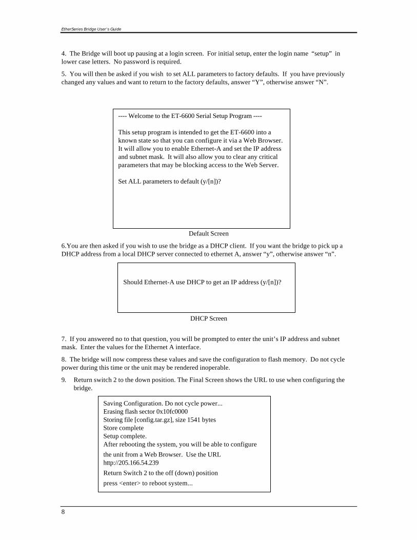
4. The Bridge will boot up pausing at a login screen. For initial setup, enter the login name “setup” inlower case letters. No password is required.
5. You will then be asked if you wish to set ALL parameters to factory defaults. If you have previouslychanged any values and want to return to the factory defaults, answer “Y”, otherwise answer “N”.
Default Screen
6.You are then asked if you wish to use the bridge as a DHCP client. If you want the bridge to pick up aDHCP address from a local DHCP server connected to ethernet A, answer “y”, otherwise answer “n”.
DHCP Screen
7. If you answered no to that question, you will be prompted to enter the unit’s IP address and subnetmask. Enter the values for the Ethernet A interface.
8. The bridge will now compress these values and save the configuration to flash memory. Do not cyclepower during this time or the unit may be rendered inoperable.
9. Return switch 2 to the down position. The Final Screen shows the URL to use when configuring thebridge.
---- Welcome to the ET-6600 Serial Setup Program ----
This setup program is intended to get the ET-6600 into aknown state so that you can configure it via a Web Browser.It will allow you to enable Ethernet-A and set the IP addressand subnet mask. It will also allow you to clear any criticalparameters that may be blocking access to the Web Server.
Set ALL parameters to default (y/[n])?
Should Ethernet-A use DHCP to get an IP address (y/[n])?
Saving Configuration. Do not cycle power...Erasing flash sector 0x10fc0000Storing file [config.tar.gz], size 1541 bytesStore completeSetup complete.After rebooting the system, you will be able to configure
the unit from a Web Browser. Use the URLhttp://205.166.54.239
Return Switch 2 to the off (down) position
press <enter> to reboot system...

Configuration
9
10. The bridge will now reboot.
2. Connect the Ethernet Cable
Connect a 10BaseT or 100Base T LAN cable to Ethernet Port A. Reboot the bridge with a power cycle or thereset switch. The bridge will now be available to any web browser on the same LAN segment. If your webbrowser does not see the bridge, verify that you do not have a proxy server configured in the browser. Ifso, properly configure the browser to bypass the proxy server for this URL.
3. Verify the IP Address Configuration
Enter the URL from step 1.8 (or http://192.168.0.1 ) into your web browser. The login screen below shouldbe displayed.
Login Screen
Log in using the user name “admin” and no password (blank field). If this screen doesn’t display, check theTroubleshooting Section in Chapter 6.
EtherSeries Bridge User’s Guide
10
4. Enter Your Configuration
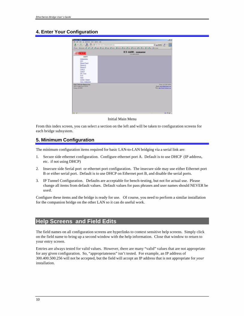
Initial Main Menu
From this index screen, you can select a section on the left and will be taken to configuration screens foreach bridge subsystem.
5. Minimum Configuration
The minimum configuration items required for basic LAN-to-LAN bridging via a serial link are:
1. Secure side ethernet configuration. Configure ethernet port A. Default is to use DHCP (IP address,etc. if not using DHCP)
2. Insecure side Serial port or ethernet port configuration. The insecure side may use either Ethernet portB or either serial port. Default is to use DHCP on Ethernet port B, and disable the serial ports.
3. IP Tunnel Configuration. Defaults are acceptable for bench-testing, but not for actual use. Pleasechange all items from default values. Default values for pass phrases and user names should NEVER beused.
Configure these items and the bridge is ready for use. Of course, you need to perform a similar installationfor the companion bridge on the other LAN so it can do useful work.
Help Screens and Field Edits
The field names on all configuration screens are hyperlinks to context sensitive help screens. Simply clickon the field name to bring up a second window with the help information. Close that window to return toyour entry screen.
Entries are always tested for valid values. However, there are many “valid” values that are not appropriatefor any given configuration. So, “appropriateness” isn’t tested. For example, an IP address of300.400.500.256 will not be accepted, but the field will accept an IP address that is not appropriate for yourinstallation.

Configuration
11
Chapter 3
The Configuration ProcessThis Chapter describes configuration management process on the ET-6600 bridge usinga Web Browser.
Overview
The ET-6600 bridge contains a quite flexible configuration management system. By using this systemcorrectly, one can remotely configure the bridge, save copies of that configuration to a PC, changeconfiguration changes for later activation, and remote transfer firmware upgrades to the bridge.
There may be up to three configuration “images” in use at any time.
1. The active configuration. Normally, this is the configuration that was loaded from memory when thebridge was last booted. However it may have been changed since boot time as described below. Thisis the configuration that is currently running the bridge.
2. The pending configuration: This is the current configuration that was loaded form memory when thebridge was last booted WITH any changes made by using the configuration screens. Thisconfiguration is NOT the configuration running the bridge at present.
3. The stored configuration. This is the configuration that was last written to the bridge’s non-volatileRAM. The next time the bridge boots, it will start running this configuration.
Note that any configuration transfer (with the Administration Configuration Transfer screen) is the workingconfiguration. You can load a configuration file from the PC, then either activate it to test it. Or, save itwithout activation if you don’t want to change the currently running.
Using the Configuration Flexibility
When the bridge starts from a power-off condition, it loads an active configuration from its non-volatilememory. This active configuration is also copied to the working configuration.
Whenever the configuration screens are used to change values, only the pending configuration ischanged… not the active configuration.
Using the configuration screens will change the pending configuration. You may change the activeconfiguration by copying the pending configuration over it. This change is performed using the “ActivateConfiguration” screen. Going to this screen activates the pending configuration by copying the pendingconfiguration over the top of the active configuration. This does not store the configuration in non-volatilememory. When the bridge is next reset or powered up, it will begin using the old stored configuration frombefore the changes and activate command. Unless…
Using the store configuration screen will copy the pending configuration into Non-volatile memory. It willnot cause this configuration to begin running the bridge. However, upon the next reset or power cycle, thebridge will begin using the stored configuration.
It is possible to activate the pending configuration using the Activate Configuration screen and then storethe configuration using the Store Configuration screen. This two step process will cause all threeconfigurations to be identical.

EtherSeries Bridge User’s Guide
12
Configuration Process Examples
Make configuration changes, test them with Activate, then save them withSave.
This is the most commonly used method for changing the bridge configuration. It allows you to test theconfiguration prior to saving it. If, during the testing, you notice an abnormality; you can reset the bridge toreturn to the last good configuration.
Make configuration changes, save them, reset the bridge to activate thechanges.
This method allows one to configure the bridge via a bridge link that will not work using the newconfiguration. Make the changes to the pending configuration and save them. Your current session willnot be affected, but when the bridge is reset, it will begin using the new configuration. This method isuseful when you are configuring a bridge to use a new LAN address range while it is on the old LAN. It’salso used when a dial-up PPP connection is the management path, and the new configuration will not allowthat PPP connection.
Transfer a saved configuration to the bridge, save it, reset the bridge toactivate the changes.
It is useful to transfer an existing bridge configuration to a PC text file for future use. Then if the bridge mustbe replaced, simply transfer that stored configuration to the new bridge.
If the PC is in the default IP address range of the new bridge (192.168.0.x subnet), then a new, out-of-the-boxbridge is easily configured using this method. Start the bridge, transfer a stored configuration file, and storeit. When the bridge is restarted, it will have the proper configuration.
Note regarding saved configurations
The saved configuration file is a simply formatted raw text file. Advanced users may wish to edit this fileusing an appropriate text editor , then transfer the changed configuration to a bridge.
Use care when performing configuration with this technique as the text configuration file must be in theproper format.
This method is ideal for automating the configuration of many bridges in a large corporate environment.

Configuration
13
Chapter 4
ConfigurationThis Chapter describes configuration screens and some configuration hints for theEtherSeries ET-6600 Bridge
Overview
The EtherSeries bridge is configured using forms displayed on a web browser. In this chapter, we illustrateall entry forms, and describe their use. This is not a tutorial on IP, PPP, or routing. Familiarity with IP andrelated information is required before you can configure any ethernet product.
All configuration screens are accessed from the main index screen shown below. They are divided intosections with only one layer of screens below the top level.
Configuration screens should only be made available via the secure interface. This default operation maybe changed during configuration, but it is highly recommended that configuration be locked to the secureinterface.
ET-6600 Splash Screen
From this index, click on a menu keyword to open the appropriate screen. In this manual, screens arediscussed in the order shown on the index screen.
EtherSeries Bridge User’s Guide
14
Administration
The Administration section contains eight screens used to configure system-wide settings and perform afew high level operations.
Admin Password
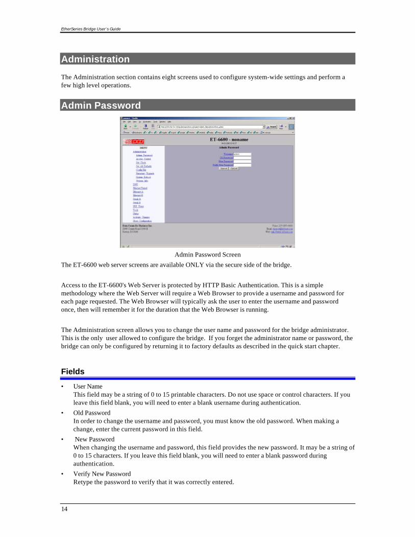
Admin Password Screen
The ET-6600 web server screens are available ONLY via the secure side of the bridge.
Access to the ET-6600's Web Server is protected by HTTP Basic Authentication. This is a simplemethodology where the Web Server will require a Web Browser to provide a username and password foreach page requested. The Web Browser will typically ask the user to enter the username and passwordonce, then will remember it for the duration that the Web Browser is running.
The Administration screen allows you to change the user name and password for the bridge administrator.This is the only user allowed to configure the bridge. If you forget the administrator name or password, thebridge can only be configured by returning it to factory defaults as described in the quick start chapter.
Fields
• User NameThis field may be a string of 0 to 15 printable characters. Do not use space or control characters. If youleave this field blank, you will need to enter a blank username during authentication.
• Old PasswordIn order to change the username and password, you must know the old password. When making achange, enter the current password in this field.
• New PasswordWhen changing the username and password, this field provides the new password. It may be a string of0 to 15 characters. If you leave this field blank, you will need to enter a blank password duringauthentication.
• Verify New PasswordRetype the password to verify that it was correctly entered.

Configuration
15
Notes
• If you forget your username or password, you can use the Serial Port Setup to erase the currentsettings and return the unit to factory defaults.
• Security Note: HTTP Basic Authentication may be easily hacked if the attacker has the ability to sniffnetwork packets. The username is transmitted in the clear and the password is transmitted in anobfuscated but easily reversed format. For this reason, configuration should only be available via thesecure ethernet interface on the bridge. This operation is configurable via the Admin Access Controlscreen.
Admin Access Control
Administrative Access Control Screen
Access Control allows you to place further restrictions on access to the ET-6600's internal web server.
Fields
• Web Server Port This is the TCP Port to use for the ET-6600's internal Web Server. Typically it is set to port 80.
However you may set it to any value between 1 and 65535.
There are several reasons that you may want to change the web server port. By changing it to a non-standard value, you reduce the chance that a random attacker will find the ET-6600's web interface and

EtherSeries Bridge User’s Guide
16
attempt to break in. A different port may be needed to accommodate local firewalling.
If you change the web server port number to any value other that 80, remember that you will have toinclude the port number in your URL. For example, http://192.168.0.1:7995
• Respond to PingThis item allows you to block ping requests to the ET-6600. Ping is a valuable tool for diagnosingnetwork problems, but can also become a security problem. Disabling ping causes the ET-6600 to notrespond to ping requests for one of its IP addresses. It has no effect on the ET-6600's passing of pingrequest and responses from other network nodes.
• Web AccessThese options allow you to block web access through the specified interface. If you are using thetunnel to bridge across a public network, you are strongly advised to disable web access from theinterface attached to the public network.
• Accepted Web IP Source AddressThis table allows you to control what hosts or networks have access to the ET-6600's web server. If
empty, any host may access the unit.
Entries are made by specifying a Target and Netmask. For example, if you want to allow only the host192.168.10.16 access, you would enter:Target: 192.168.10.16 Netmask:255.255.255.255.
If you wanted to allow access to all hosts in the range 192.168.10.1 to 192.168.10.255, you would enter:
Target: 192.168.10.0 Netmask: 255.255.255.0
• Target Host or Network address.
• Netmask If blank or set to 255.255.255.255, target is assumed to be a host address. Otherwise, target istreated as a network address.
Notes
Remember to submit the change by clicking the “SUBMIT” button.

Configuration
17
Set Clock
Set Clock Screen
This form allows you to set the ET-6600's software clock. The setting will take effect when you "ActivateChanges".
Fields
• Year Year in the range 2000 to 2035.
• Month Numeric value of month in the range 1 to 12.
• Day Day of month in the range 1 to 31.
• Hour Hour of the day in the range 0 to 23.
• Minute Minutes in the range 0 to 59.
Notes
• If you save the time to non-volatile memory, the clock will be set to the specified time at each reboot.
• The ET-6600 does not contain a real-time clock, nor has the ability to remember the current time acrossreboots. The software clock is used for time stamping log entries.
• The default values shown on this screen are the “boot” values… not the current time.

EtherSeries Bridge User’s Guide
18
Set All Defaults
Set All Defaults Screen
This form will allow you to set all tunnel parameters to their default value. Before you "Activate Changes",you should configure the interface that you are using to access the tunnel. Otherwise, all interfaces exceptEthernet-A will be disabled and Ethernet-A will be configured with the IP address of 192.168.0.1.
Configuration File
Configuration File Screen
This form will allow you to copy the bridge’s configuration to a file on your PC. You can also use the formto transfer a configuration file from your PC to the bridge.
Fields
• File to Transfer This is the name of the configuration file on your PC to be transferred to the bridge.

Configuration
19
• Transfer file to PC (action)Transfers the current bridge configuration file to this PC.
• Transfer file to Bridge (action)Transfers the named file to the bridge.
Notes
• The configuration file is a specially formatted text file. It may be edited with any text editor.
• You may save multiple configuration files on the PC by using different names for them.
• After transferring a configuration file to the bridge, you may either activate the changes (with theactivate screen), or store the changes (with the store configuration screen). If you activate thechanges, the bridge will immediately begin using the new configuration. If the changes are stored, thebridge will use the new configuration only after a reboot or reset.
• Be sure that you can access the bridge using its new configuration if you activate the newconfiguration. Otherwise, it may be necessary to return to the old stored configuration with a reset.
• You must SECURE this text file on your PC with encryption, or move it to a secure place. Access to thesaved configuration file may compromise the security of your ET-6600
Firmware Upgrade
Firmware Upgrade Screen
This form will allow you to load new firmware into the ET-6600. The firmware will be saved to non-volatilememory, replacing the current firmware.

EtherSeries Bridge User’s Guide
20
Fields
• File NameThis is the name of the firmware image file to be transferred to the bridge.
• Upgrade Firmware (action)Pressing this button transfers the firmware image to the bridge and upgrades it.
Notes
You should only use a firmware image obtained directly from DCB.
System Reboot
System Reboot Screen
This form will allow you to reboot the ET-6600. If you have configuration changes that have not been savedto non-volatile memory, they will be lost.
This is a way to revert back to your previously stored configuration.
Fields
• Reboot System (action)This causes the bridge to reboot and use its stored configuration.
Notes
• The current configuration is not retained unless it has been previously stored.

Configuration
21
Version Information Screen
Version Information Screen
This screen displays current firmware and hardware version information as well as some copyright notices.
DNS
DNS Screen
The Domain Name System, DNS, is a distributed database used by applications to map between IPaddresses and hostnames. The ET-6600 has support for the client side of DNS. It does not act as a DNSserver. The DNS settings are passed to remote PPP users and DHCP clients. Use of DNS is optional.
Fields
• HostName The name given to the ET-6600. If you enter a name, it will also be displayed on the title of the webpages.

EtherSeries Bridge User’s Guide
22
• Domain The name of the local domain. For example: widgets.com
• Primary DNS Server The IP address of the primary DNS server. This value will be provided to remote PPP users duringoption negotiation.
• Secondary DNS Server The IP address of the secondary DNS server. This value will be provided to remote PPP users duringnegotiation.
Notes
• The bridge does not act as a DNS server.
• The DNS settings are passed to remote PPP users
• Use of DNS is optional.
Ethernet A/B Configuration
Ethernet Configuration Screen
The ET-6600 may contain two Ethernet interfaces. Ethernet-A is a 10/100 controller configured for auto-sense. Ethernet-B is 10BaseT only. Ethernet port A is the local, secure side of the tunnel. The publicnetwork interface may be either Ethernet port B, or one of the two serial ports. If used, ethernet B is alwaysthe insecure side, and is usually used with a broadband WAN connection. This screen is used to configureboth IP parameters and DHCP server parameters (if the DHCP server function is used)
Fields
• Enable/Disable Each interface may be individually enabled or disabled. If you do not plan to use an interface, it is agood idea to disable it. Doing so will free up system resources.
• DHCP Fields Dynamic Host Configuration Protocol, DHCP, is a client/server protocol automating the configurationof systems using TCP/IP. Client systems will broadcast a request asking for configuration. Serversystems will respond, assigning the client system an IP address and providing other relatedconfiguration information such as subnet mask, DNS, and gateway addresses.

Configuration
23
If you enable DHCP Client, the tunnel will request for configuration from a DHCP server. It is commonto enable DHCP client on a broadband interface to an Internet Service Provider. In the case of thetunnel, that would be Ethernet-B.
When DHCP Client is enabled, the IP Address and Netmask fields are ignored.
• IP Address an IP address is a numeric identifier given to an interface. It consists of four 8-bit numbers and isrepresented in a dotted notation. An example of an IP address is "192.168.0.10". An Ethernet IP addressmust be unique within your network. If you are directly connected to the Internet, it must globallyunique.This field is not used if DHCP Client has been enabled. The DHCP server will assign the IP address.
• Subnet Mask A subnet mask is a bit mask applied against the IP address. It specifies which portion of the IP addressis the subnet identifier and which portion is the host identifier. For example, many subnets have a maskof 255.255.255.0. This means the first 24 bits of the address is the subnet identifier and the last 8 bits isthe host identifier.
This field is not used if DHCP Client has been enabled. The subnet mask will be assigned by the DHCPserver.
Notes
• If DHCP client mode is used, the IP address fields are ignored.
• For maximum throughput, always disable unused interfaces.
Static Routes Screen
Static Routes Screen
The tunnel maintains four tables of Static Routes. There is one for each possible interface, namely Ethernet-A, Ethernet-B, Serial-A, and Serial-B. The routes defined in the associated table are applied when aninterface comes up and are removed when an interface goes down. It is important that routes be placed inthe correct table. The rule-of-thumb is to apply a route to the interface that the routed packet should go out.For example, if you want your default route to go out the PPP link on Serial-A, you would add the default

EtherSeries Bridge User’s Guide
24
routing entry to Serial-A's static routing table. If you want packets to address 192.168.10.54 to go outEthernet-A, you would add a routing entry to Ethernet-A's table.
The tunnel will automatically create a route for each interface. For Ethernet, this will be a network entrybased on the IP address and netmask of the interface. For PPP links, this will be a host entry for the IPaddress of the remote PPP device.
You can view that Active Routing Table from the Status Menu/Routing Table.
Fields
• Target Destination Host or Network address. Use a target address of 0.0.0.0 to specify a default route.
• Netmask If left blank or set to 255.255.255.255, the target is assumed to be a host address. Otherwise, the targetis assumed to be a network address and the netmask specifies which address bits are significant.
• Gateway The IP address of where to forward packets to. The Gateway field is only available for Ethernetinterfaces. If you leave it blank, the ET-6600 will assume the target is on the local network segment.
Notes
• Use a netmask of 0.0.0.0 to specify a default route.
• PPP links do not need a gateway address as the remote PPP device is the only possible gateway
Address Filters Screen
Address Filters Screen
The tunnel can be configured to drop all packets except those with an approved source address. This isconfigured separately for each interface and occurs as packets are received on the interface.

Configuration
25
This feature allows one to limit tunnel client connections from the public side of the bridge.
If all entries in the table are blank, all addresses are accepted.
Fields
• IP Address Host or Network source IP address to allow.
• Netmask If the Netmask is blank or 255.255.255.255, the IP address is treated as a host address. Otherwise the IPaddress is treated as a network address and the netmask indicates the significant bits.
Notes
CAUTION: Keep in mind that you may prevent access to the ET-6600's internal web server through theassociated interface filters.
Serial A/B Operating Mode Screen
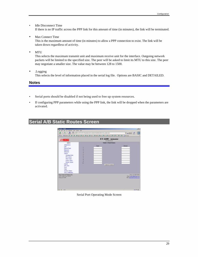
Serial Port Operating Mode Screen
This form sets the operating mode and parameters for the serial ports..
Fields

EtherSeries Bridge User’s Guide
26
Mode Sets the operating mode of the port. Currently PPP is the only mode supported. The port should be disabledif it is not being used. This will free up system resources.
• Baud Rate Serial port Baud rate.
• Word Size Number of data bits in each character. For PPP, this field is ignored and the number of bits is set to 8.
• ParityEnable parity generation and testing.
• Stop BitsSelect 1 or 2. The ET-6600 does not support 1.5 stop bits.
• Flow ControlHardware flow control enable. The ET-6600 uses the RTS and CTS signals for hardware flow control.RTS is an output from the ET-6600. It will be asserted when the ET-6600 is ready to receive data and de-asserted when the ET-6600 is not ready to receive data. CTS is an input to the ET-6600. The ET-6600 willmonitor CTS and will only transmit data when CTS is asserted.
Notes
• Serial ports should be disabled if not being used to free up system resources.
• If configuring PPP parameters while using the PPP link, the link will be dropped when the parameters areactivated.

Configuration
27
Serial A/B PPP Options Screen
Serial Port PPP Options Screen
This form is used to configure the PPP options for the serial interface
Fields
• This option effectively enables and disables the modem dialing optionsWhen set to direct, the ET-6600 assumes a hard-wired connection and directly attempts to establish aPPP connection. Modem related options are ignored.
• Dial-INWhen set to yes, the modem is configured to answer incoming calls. The PPP session will beestablished when the serial ports DCD (data carrier detect) signal goes active.This feature may be used in conjunction with dial-out on-demand. YES.
• Dial-OUTWhen set to yes, the ET-6600 will immediately try to establish a PPP session by dialing the phone.When set to on-demand, the ET-6600 will create a pseudo PPP session and wait for outbound traffic.When traffic is detected, it will attempt to dial-out and establish a real PPP session.
Note: When on-demand is selected, you must set Local IP and Remote IP addresses. You also need toset at least one entry in Static Routes for the remote network. This is the information needed by the ET-6600 to determine outbound traffic.
• Phone NumberThis is the phone number to use when making a dial-out call. This field is not only limited to phonenumbers. If necessary, you may embed modem commands. This field is simply appended to the ModemOptions - Dial field when making an outgoing call.
• Local IPEach side of a PPP connection must have an IP address. This is the IP address to use for the local PPPdevice. You can leave this field blank, but the remote PPP device must be configured to assign anaddress.

EtherSeries Bridge User’s Guide
28
With the ET-6600, it is possible to borrow the IP address of one of the Ethernet interfaces for the LocalIP address. However, this bad practice as it might expose the web configuration screens to the publicinterface.
• When Dial-out on-demand is enabled, you must specify a Local IP. This may pose a problem whendialing an ISP that dynamically assigns the local address. To get around it, set the Local IP address tothe address of one of the Ethernet interfaces. The ET-6600 will switch to the server assigned PPPaddress when the connection is established.
• Remote IPEach side of a PPP connection must have an IP address. This is the IP address to assign to the remotePPP device. You can leave this field blank, but the remote PPP device must be configured with a LocalIP address.
When Dial-out on-demand is enabled, you must specify a Remote IP. This may pose a problem whendialing an ISP where you don't know what the address of the remote device will be. In reality, you don'thave to know the exact address. Something close will do. Choose the address of a device on the remotenetwork such as a next-hop bridge, DNS server, or mail server. When the real PPP connection isestablished, the ET-6600 will switch to the server's real IP address.
• Force Remote IPWhen this option is enabled, the peer will be forced to use the Remote IP address, overriding the peer'sconfiguration. If it refuses, the connection will be terminated. When this option is disabled, the peer's IPaddress will be used, if it has been configured with one. You would typically enable this if the tunnel isbeing used as a dial-in server.
• UserNameThis is the user-name to use when authenticating to a remote system. In other words, this is the user-name sent to the remote system. This field is optional. If the remote system does not requireauthentication, you may leave this field blank. The user-name may be a string of 1 to 15 printablecharacters. No space or control characters.
• PasswordThis is the password to use when authenticating to the remote system. In other words, this is thepassword sent to the remote system. This field is optional. If the remote system does not requireauthentication, you may leave this field blank. The password may be a string of 1 to 15 printablecharacters. No space or control characters.
• AuthenticationWhen set to pap or chap the remote system must provide a user-name and password in order toconnect to the local system. The list of valid user-names and passwords are entered in the PPP Userstable. When pap is selected, the remote system must use the Password Authentication Protocol (PAP).
When chap is selected, the remote system must use the Challenge Handshake Authentication Protocol(CHAP). This includes MSCHAP V1 and V2
Note: CHAP is considered the better of the two authentication methods.
• DNS Addresses
When set to request, the local tunnel will request DNS addresses from the remote tunnel during PPPoption negotiation. When set to provide, the local tunnel will provide DNS addresses to the remotetunnel during PPP option negotiation.
Note: Typically you would select request if you are dialing into an ISP. You would select provide if youare using the tunnel as a dial-in server.
Configuration
29
• Idle Disconnect TimeIf there is no IP traffic across the PPP link for this amount of time (in minutes), the link will be terminated.
• Max Connect TimeThis is the maximum amount of time (in minutes) to allow a PPP connection to exist. The link will betaken down regardless of activity.
• MTUThis selects the maximum transmit unit and maximum receive unit for the interface. Outgoing networkpackets will be limited to the specified size. The peer will be asked to limit its MTU to this size. The peermay negotiate a smaller size. The value may be between 128 to 1500.
• .LoggingThis selects the level of information placed in the serial log file. Options are BASIC and DETAILED.
Notes
• Serial ports should be disabled if not being used to free up system resources.
• If configuring PPP parameters while using the PPP link, the link will be dropped when the parameters areactivated.
Serial A/B Static Routes Screen
Serial Port Operating Mode Screen

EtherSeries Bridge User’s Guide
30
The tunnel maintains four tables of Static Routes. There is one for each possible interface, namely Ethernet-A, Ethernet-B, Serial-A, and Serial-B. The routes defined in the associated table are applied when aninterface comes up and are removed when an interface goes down. It is important that routes be placed inthe correct table. The rule-of-thumb is to apply a route to the interface that the routed packet should go out.For example, if you want your default route to go out the PPP link on Serial-A, you would add the defaultrouting entry to Serial-A's static routing table. If you want packets to address 192.168.10.54 to go outEthernet-A, you would add a routing entry to Ethernet-A's table.
The tunnel will automatically create a route for each interface. For Ethernet, this will be a network entrybased on the IP address and netmask of the interface. For PPP links, this will be a host entry for the IPaddress of the remote PPP device.
You can view that Active Routing Table from the Status Menu/Routing Table.
Fields
• Target Destination Host or Network address. Use a target address of 0.0.0.0 to specify a default route.
• Netmask If left blank or set to 255.255.255.255, the target is assumed to be a host address. Otherwise, the target isassumed to be a network address and the netmask specifies which address bits are significant. Use anetmask of 0.0.0.0 to specify a default route.
Notes
• The ET-6600 will automatically create a route for each interface. For Ethernet, this will be a networkentry based on the IP address and netmask of the interface. For PPP links, this will be a host entry forthe IP address of the remote PPP device.
• You can view that Active Routing Table from the Status Menu/Routing Table.
• There is no gateway field as all routes terminate at the other end of the serial link.
The Port Forwarding screen is identical to the Ethernet Port Forwarding screen. See that section for details.

Configuration
31
Serial A/B Modem Options Screen
Serial Port Modem Options Screen
The Modem Options are used when the PPP Connect Type has been set to modem. They specify thevarious commands to send to the modem, depending on the selected PPP options.
When configuring your modem, there are several items you should consider in order for the tunnel tocorrectly inter-operate with it.
* The tunnel monitors Data Carrier Detect (DCD) to bring up and take down PPP sessions The modemshould assert (DCD) when a connection is established and drop DCD when a connection is lost.
* The tunnel will assert DTR when it is ready to establish a PPP session and will drop DTR when a PPPsession is terminating. The modem should hang up the phone if DTR is inactive. Likewise it should notanswer an incoming call if DTR is inactive.
* Do not suppress the "OK" message. The tunnel looks for this message to determine when commandshave been accepted.
* Suppress echo.
* The tunnel will look for the messages "BUSY", "NO CARRIER", "CARRIER", "NO DIALTONE", and"NO ANSWER" when dialing a connection. You should not suppress result messages
Fields
Init 1The ET-6600 will send this command prior to starting each PPP connection. You should use it to put themodem into a known state. For DCB's D-Series modem, you should use the string:"AT&FE0V1&C1&D2&K3N1X4"
Init 2 The ET-6600 will send this command after sending the first initialization command and receiving an
"OK" response. This is to allow for additional configuration or to allow for modems that can not be resetand configured with a single command string.
DialThis command will be used when the ET-6600 needs to dial-out. It will be concatenated with the phone

EtherSeries Bridge User’s Guide
32
number specified in the PPP options. For most modems, the command is "ATDT" to do touch-tone dialingand "ATDP" to do pulse-code dialing.
Answerhis command will be used when the ET-6600 needs to enable auto-answer mode. For most modems, thecommand is "ATS0=1", where the 1 specifies how many rings to wait for before answering.
No AnswerThis command will be used when the ET-6600 needs to disable auto-answer mode. For most modems, thecommand is "ATS0=0".
HangupThis is the command used to hang-up the connection. For most modem, the command is "ATH". The ET-6600 will initially use the DTR signal to hang-up a connection. However, if the modem does not drop theDCD signal, the ET-6600 will issue "+++" wait for an "OK" response, then send this command.
Sample Modem ConfigurationsThere are several sample configurations for DCB and other brand modems. When one of these is selected,the default values above are set correctly for the modem type selected.
Notes
The ET-6600 will look for the messages "BUSY", "NO CARRIER", "CARRIER", "NO DIALTONE", and "NOANSWER" when dialing a connection. You should not suppress result messages
Configuration
33
PPP Users Screen
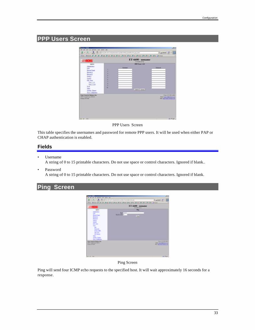
PPP Users Screen
This table specifies the usernames and password for remote PPP users. It will be used when either PAP orCHAP authentication is enabled.
Fields
• UsernameA string of 0 to 15 printable characters. Do not use space or control characters. Ignored if blank..
• PasswordA string of 0 to 15 printable characters. Do not use space or control characters. Ignored if blank.
Ping Screen
Ping Screen
Ping will send four ICMP echo requests to the specified host. It will wait approximately 16 seconds for aresponse.

EtherSeries Bridge User’s Guide
34
Fields
• Host IP address of the target host. If hostname DNS is enabled, you may use a hostname.
• SizeNumber of data bytes to send.
Notes
• Ping and traceroute are useful tools to determine if routing is correct.
• Ping may also be used to ”force” a dial-up connection to dial.
Dial Tools Screen
Dial Tools Screen
This screen is used to test and manage the serial lines. The action buttons allow a dial operation to beforced or a connection to be terminated on each interface.
Notes
• Check the port status screens to verify that the disconnect or dial operation was performed correctly.
Configuration
35
ISP Fail-over Screen
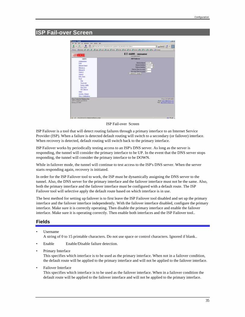
ISP Fail-over Screen
ISP Failover is a tool that will detect routing failures through a primary interface to an Internet ServiceProvider (ISP). When a failure is detected default routing will switch to a secondary (or failover) interface.When recovery is detected, default routing will switch back to the primary interface.
ISP Failover works by periodically testing access to an ISP's DNS server. As long as the server isresponding, the tunnel will consider the primary interface to be UP. In the event that the DNS server stopsresponding, the tunnel will consider the primary interface to be DOWN.
While in failover mode, the tunnel will continue to test access to the ISP's DNS server. When the serverstarts responding again, recovery is initiated.
In order for the ISP Failover tool to work, the ISP must be dynamically assigning the DNS server to thetunnel. Also, the DNS server for the primary interface and the failover interface must not be the same. Also,both the primary interface and the failover interface must be configured with a default route. The ISPFailover tool will selective apply the default route based on which interface is in use.
The best method for setting up failover is to first leave the ISP Failover tool disabled and set up the primaryinterface and the failover interface independently. With the failover interface disabled, configure the primaryinterface. Make sure it is correctly operating. Then disable the primary interface and enable the failoverinterface. Make sure it is operating correctly. Then enable both interfaces and the ISP Failover tool..
Fields
• UsernameA string of 0 to 15 printable characters. Do not use space or control characters. Ignored if blank..
• Enable Enable/Disable failure detection.
• Primary Interface This specifies which interface is to be used as the primary interface. When not in a failover condition,the default route will be applied to the primary interface and will not be applied to the failover interface.
• Failover Interface This specifies which interface is to be used as the failover interface. When in a failover condition thedefault route will be applied to the failover interface and will not be applied to the primary interface.
EtherSeries Bridge User’s Guide
36
• Failover Time If the primary interface is down for this period of time the tunnel switches to failover mode. This time isset in seconds. The actual test interval will be 1/5 this time. 5 consecutive failures will trigger thefailover.
Make sure you do not set this value too low for the primary interface. For example, if the primaryinterface is through a modem, make sure to allow for dial and connect time. This could be more than 30seconds. If the primary interface is through an Ethernet port make sure to allow time for 10/100negotiation and DHCP service.
• Recovery Time If the primary interface is up for this period of time the tunnel will switch out of failover mode. This timeis set in seconds. The actual test interval will be 1/5 this time. 5 consecutive responses will triggerrecovery.
Notes
Make sure to add a static default route for both the primary and failover interface. The tunnel will selectivelyapply the default route depending whether or not there is a failover condition. For Ethernet interfaces, this isnot necessary if DHCP client is enabled and the DHCP server supplies a default route.
Don't be to aggressive on your Failover Time setting. If the value is too low, the tunnel may get stuck in asituation where it never recovers.
Each time the tunnel switches interfaces, both primary and failover interfaces are taken down then broughtback up. This is necessary to clear out any NAT associations and to clear out all old cached routes from therouting table. For dial-up connections, this means that the modem will be disconnect if currently connected.
Traceroute Screen
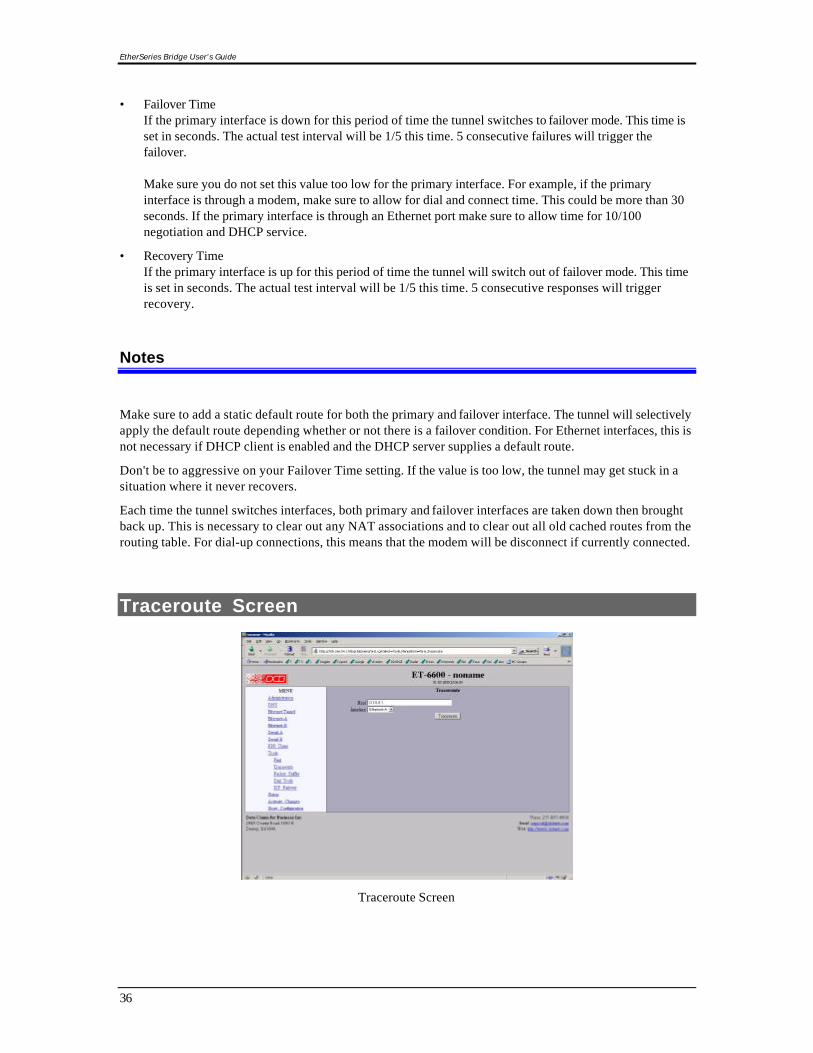
Traceroute Screen
Configuration
37
Traceroute displays the route that a packet will take to reach another host. This is performed by sendingUDP packets to port 33434 with progressively larger Time-to-Live values and listening for ICMP TIME-EXCEEDED responses from the bridges along the way.
Fields
HostIP address of the target host. If hostname DNS is enabled, you may use a hostname.
InterfaceWhich interface to use. The routing table is bypassed.
Notes
Packet Sniffer Screen
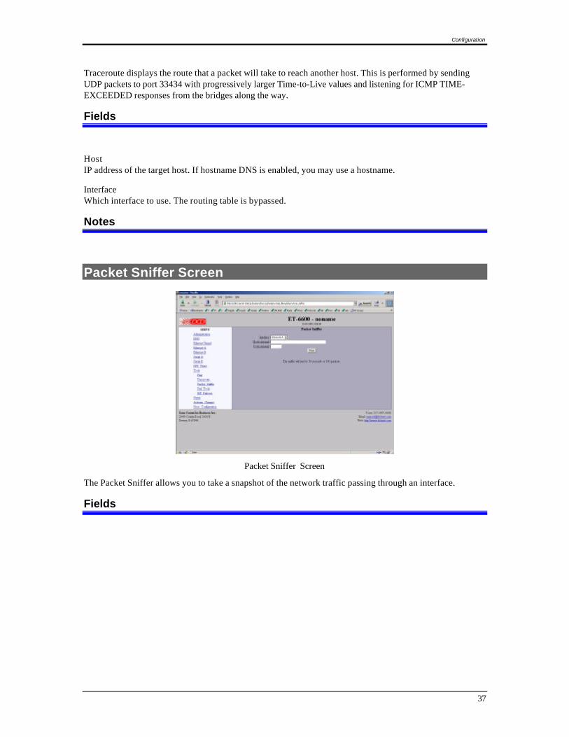
Packet Sniffer Screen
The Packet Sniffer allows you to take a snapshot of the network traffic passing through an interface.
Fields
EtherSeries Bridge User’s Guide
38
• Interface Which interface to use. If the interface is a serial port, you will only see the traffic that is passingthrough the IP layer of PPP. You will not see low-level PPP traffic.
• HostThis applies a host filter. Only packets with a matching source or destination IP address will be includedin the trace.
• PortThis applies a port number filter. Only TCP or UDP packets with a matching source or destination portnumber will be included in the trace..
Notes
• Only packet headers are shown with the. You will not be able to see the data contents of the packets.

Configuration
39
Interface Status Screen
Status Screen
The Interface Status screen shows port status and packet counters for each interface on the ET-6600
Serial A/B Log Screen
Interface Log Screen
The Interface Log screen shows important events logged for each interface on the ET-6600
EtherSeries Bridge User’s Guide
40
User Log Screen
User Log Screen
The User Log screen shows connect and disconnect events logged at the system level on the ET-6600. Nologging is performed if PPP authentication is disabled.
User Summary Screen
User Summary Screen
The User Summary screen shows connection detail by user on the ET-6600

Configuration
41
Routing Table Screen
Routing Table Screen
The Routing Table screen shows all routes configured in the ET-6600
Store Configuration Screen
Store Configuration Screen
The Store configuration screen is used to store the current configuration to non-volatile memory. Thisdoes not activate configuration changes. Configuration changes are made to a temporary area. They maybe “activated” using the Activate Changes screen, in which case they will become immediately active,overwriting the pre-existing configuration for the duration of this session; or,, they may be “stored” usingthis screen, in which case they will be written to non-volatile memory and used at the next reset or power-up.

EtherSeries Bridge User’s Guide
42
Tunnel Log Screen
Tunnel Log Screen
The Tunnel Log File Screen displays a record of all key changes, connections, authentications, anddisconnects.
Tunnel Nodes Screen
Tunnel Nodes Screen
The Tunnel Nodes Screen displays currently connected remote nodes. These are other ET-6600 units thathave authenticated with this unit.
Configuration
43
Tunnel Addresses Screen
Tunnel Addresses Screen
The Tunnel Addresses Screen displays the MAC address, interface location, number of packets passed,and time of the last packet received from tunneled nodes.
DHCP Client Log Screen
DHCP Client Log Screen
The DHCP Client Log Screen displays recent history of DHCP client activity.

EtherSeries Bridge User’s Guide
44
ISP Fail-over Log Screen
ISP Failover Log Screen
The ISP Failover Log Screen displays recent history of ISP Fail-over operation.

45
Chapter 5
OperationThis Chapter explains how to use the ET-6600, once it is installed and configured.
Common Uses – Overview
Some of the most commonly used configurations are for:
• Remote LAN connected to local LAN via dial-in PPP
• Remote LAN connected to local LAN via broadband ISP Internet connection
• Remote LAN connected to local LAN via a dedicated communications link.
• LAN-to-LAN connection using dial on demand (DOD).
Any of these connection methods may have the data transverse the Internet, a private network, variousfirewalls, NAT servers, and other routes. Although any ethernet protocol may be bridged (including UDP,IP, Netbios, Appletalk, etc) the connection between two ET-6600 units is via TCP/IP, therefore a TCPconnection is required between the two ET-6600 units. The ET-6600 serial ports support PPP.
These configurations are detailed in this chapter. Some sample configuration files may be downloaded fromthe DCB support web site and then transferred to your bridge.
The local or remote LAN may be a full-fledged network or a single PC using an ethernet cross-over cable.
The ET-6600 link requires one unit to be configured as a server, and one or more units configured as clients.A single ET-6600 may function as both a server and a client.
Remote LAN to Local LAN via PPP
A server ET-6600 is connected to the host remote LAN and configured for dial-in PPP on one serial port.The remote ET-6600 client is configured as a PPP dial-in client, and a laptop is connected to its Ethernet Aport via a cross-over cable.
Remote LAN to Local LAN via Broadband Internet
The server ET-6600 is connected to the host remote LAN and eventually connected to the Internet via someISP. The remote client ET-6600 is connected to a broadband router via Ethernet B, and a local LAN isconnected to Ethernet A. All PCs on the local LAN are bridged to the remote LAN.
Remote LAN to Local LAN via Dedicated Serial Link
A server ET-6600 is connected to the host remote LAN and configured for direct-connect PPP on one serialport. The remote ET-6600 client is configured as a PPP direct connect client, and a laptop is connected to itsEthernet A port via a cross-over cable, or the remote LAN is connected to Ethernet A. A dedicated seriallink connects the serial PPP ports on the two ET-6600 units.

EtherSeries Bridge User’s Guide
46
Remote LAN to Local LAN via PPP with Dial on Demand
Similar to the PPP connection above, however the PPP is simply configured for Dial on Demand. Wheneverthe ET-6600 senses a packet to transfer to the other LAN, it dials up the remote site automatically.

Troubleshooting
47
Chapter 6
TroubleshootingThis chapter outlines some problems that may occur during installation or operation andsome possible solutions to them.
If you follow the suggested troubleshooting steps and the EtherSeries bridge still does not functionproperly, please contact your dealer for further advice.
Hardware Problems
Before anything else, check that all cables are wired correctly and properly connected.
P: All the LEDs are off.S: Check the power supply or power connection.
P: When using 10/100Base-T cabling, the unit does not work.S: Check the Hub’s link LED for the port to which the bridge is connected. If it is off, make sure the
network cable between the bridge and hub is in good condition.
Can't Connect via the LAN
P: Can't connect with a Web Browser.S: Check the following:
• Start troubleshooting from a known state. Power the bridge OFF and ON to reboot.
• Is a proper IP address configured in the bridge and PC?
• “Ping” the bridge to see if it responds. From the Windows command prompt or “Run” dialog box,use the command:
ping IP_Address
Where IP_Address is the IP Address of the bridge (e.g. ping 192.168.0.1 ). If it does notrespond, then check all LAN connections. If the LAN connection are OK, the problem is in theLAN addresses or routing The most common problem cause is incorrect IP addressconfigurations. Make sure the workstation and bridge have compatible IP addresses.
• It may be that your "ARP table" contains invalid entries. You can clear the "ARP table" byrebooting, or, on Windows95 , by typing the following command at the command prompt or Rundialog box.: ARP * -d
• Check that you are using the proper Ethernet connection on the bridge. Only Ethernet Port Aworks at 100BaseT, and the port in use must be enabled. Ethernet Port A is the local, secure side.
• The bridge is meant to be connected to a hub or ethernet switch. If connected directly to a PC, anethernet cross cable must be used.

EtherSeries Bridge User’s Guide
48
• In some cases, “smart” hubs and switches must be power-cycled to clear their internal ARP cache.This is often a problem on test bench setups where IP addresses are moved between differentequipment or a unit is moved between ethernet switch receptacles.
Other Problems
P: Can’t run the initial configuration program using a serial cable connection.S: Check that:
• The communication parameters are set properly.
• Disconnect and reconnect the power supply to the bridge with switch two UP.
• Power is available... an LED is on.
• The terminal program is operating properly. Try a loopback connector at the bridge end of thecable to verify program operation and the proper COM: port.
• The most common problems causing this symptom are incorrect RS-232 wiring or the WindowsHyperterm program not operating correctly.
Checking Bridge Operation
Once the bridge is installed on your Network, you verify proper operation by testing its functionality.Attempt to send packets through it, to verify its operation. The procedure is as follows.
From a PC on one side of the bridge, ping a PC on the other side of the bridge, or attempt a web connectionto a web server on the other side of the bridge. If either method succeeds, then two-way operation isconfirmed.
If any one PC on one side of the bridge can communicate with any single PC or server on the other side ofthe bridge, then the bridge configuration is likely correct and other problems should be investigated with alarger view of the network in mind.
Remember that this unit is a bridge, not a router. All IP addresses should be in the same IP subnet addressrange.

49
Appendix A
Specifications
EtherSeries ET-6600 Bridge Specifications
• Flash Memory: 4 Mbytes
• SRAM: 8 Mbytes
• LAN A Interface: 10/100BaseTx, Autosense
• LAN B Interface: 10BaseT
• RS-232: Two male DE-9 connectors (PC –9 Pin)
• RS-232 speed: Up to 230.4.2 Kbps
• CPU: Motorola Coldfire 5272 CPU 66 Mhz
• OS: uClinux
• Power: 9 to 12 VDC 600mA or Optional power supplies
• Switch: Configuration, Reset
• LED:8 (Status, Serial Activity, LAN Activity, Power)
• Default IP address: 192.168.0.1
• Browser Management port: 80
• Operational Temperature -40C to +85C subject to power supply limitations
EtherSeries Bridge User’s Guide
50
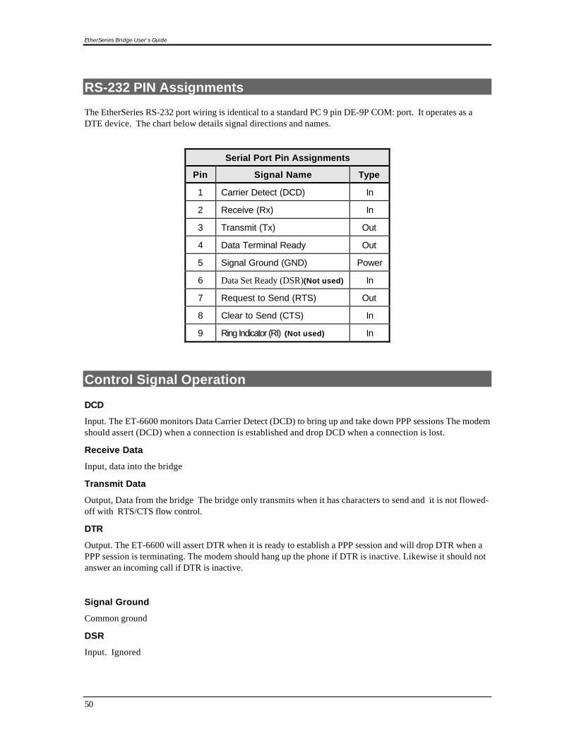
RS-232 PIN Assignments
The EtherSeries RS-232 port wiring is identical to a standard PC 9 pin DE-9P COM: port. It operates as aDTE device. The chart below details signal directions and names.
Serial Port Pin Assignments
Pin Signal Name Type
1 Carrier Detect (DCD) In
2 Receive (Rx) In
3 Transmit (Tx) Out
4 Data Terminal Ready Out
5 Signal Ground (GND) Power
6 Data Set Ready (DSR)(Not used) In
7 Request to Send (RTS) Out
8 Clear to Send (CTS) In
9 Ring Indicator (RI) (Not used) In
Control Signal Operation
DCD
Input. The ET-6600 monitors Data Carrier Detect (DCD) to bring up and take down PPP sessions The modemshould assert (DCD) when a connection is established and drop DCD when a connection is lost.
Receive Data
Input, data into the bridge
Transmit Data
Output, Data from the bridge The bridge only transmits when it has characters to send and it is not flowed-off with RTS/CTS flow control.
DTR
Output. The ET-6600 will assert DTR when it is ready to establish a PPP session and will drop DTR when aPPP session is terminating. The modem should hang up the phone if DTR is inactive. Likewise it should notanswer an incoming call if DTR is inactive.
Signal Ground
Common ground
DSR
Input. Ignored

Specifications
51
RTS
Output. Input flow control. When the internal buffer reaches the “Flow Off” buffer level, this signal islowered. When the buffer level decreases to the “Flow ON” buffer level, this signal is raised. When pin 6input is LOW, the serial interface turns OFF the pin 4 (DTR) and 7 (RTS) output signals.
CTS
Input. When Flow Control is set for CTS/RTS, lowering this signal will halt data flow from the bridge's RS-232 port.
Ring Indicator
Not used

EtherSeries Bridge User’s Guide
52
CABLES
Commonly used cable connections:
To PC 9-pin COM: port
IP6600
1,6234578
P C
432
1,6587
This null-modem crossover cable is easily constructed by combining a “PC-Direct” adapter hood and a“Remote-PC” adapter hood along with a straight through 10BaseT cable. This cable is used forconfiguration and is provided with the bridge.
Bridge to Modem
Use any commercially available PC-to-modem cable. OR, use a “Remote-PC” adapter hood and an“Asynchronous Modem” adapter hood along with a straight through 10BaseT cable. This cable isprovided with the bridge by replacing the above cable adapter hood with the “Asynchronous Modem”adapter hood.
Bridge to hub or ethernet switch
Use any commercially available 10/100BaseT cable. If using 100BaseT, an appropriately rated cable isrequired.
Bridge to PC crossover ethernet cable
A crossover cable may be constructed to allow the bridge ethernet port to directly connect to a PC withoutusing a hub.
Use the following pinout:
ET-6600 - PC
1 - 3
2 - 6
3 - 1
6 - 2

Specifications
53
Appendix B
Open Source Software InformationThe ET-6600 bridge was designed in conjunction with Open Source Linux software..
Introduction
The ET-6600 bridge was designed and programmed with Open Source Linux software in mind. The coreLinux operating system is uClinux, available from http://www.uclinux.org . DCB supports the Open Sourcesoftware effort and is appreciative of the contribution many open source developers have made to thecommunity
Other open source software used in this product may be obtained from the original developers, and is madeavailable in accordance with GNU licensing terms.
Obtaining the Source Code
For more information on obtaining the source modules for open source code used in this product, send awritten request to the following address. Code is provided on CDROM. According to GNU licensing terms,a duplication fee may be charged.
Open Source Software AdministratorData Comm for Business, Inc.2949 CR 1000 EDewey, IL. 61840

EtherSeries Bridge User’s Guide
54
Appendix C
ET-6690 Internal Modem OptionThe ET-6600 family consists of various models with different internal hardware orfirmware options. The ET-6690 includes an internal V.92 modem.
Introduction
The ET-6690 model bridge contains an internal V.92 modem instead of RS-232 Serial Port B. Theconfiguration is similar to the ET-6600 model with the following changes.
Configuration Differences
The internal modem conforms to V.92 specifications. Serial B Operating Modes are either PPP orDisabled. Modem configuration string options may be changed to suit your environment, howeverthe default value of “Internal Modem” is recommended.
ET-6690 Front Panel
The front panel contains modem indicator LEDs for RD, CD, TD, and DTR along with an RJ-11telephone line jack. Any standard RJ-11 telephone cable may be used for the phone lineconnection.
Figure C: EtherSeries Bridge Front Panel
Label Name OperationRD Receive Data Flickers along with data received from the telephone lineTD Transmit Data Flickers along with data transmitted to the telephone lineCD Carrier Detect Indicates carrier is received from another modemDTR Data Terminal Ready Indicates the bridge has raised the internal DTR signal
Figure C1 LED Indicators