Embed Size (px)
Citation preview

1/15/2016
1
ET 332b
Ac Motors, Generators and Power Systems
1lesson14_et332b.pptx
Learning Objectives
lesson14_et332b.pptx 2
After this presentation you will be able to:
� List the characteristics of NEMA Design motors.� Identify and interpret motor nameplate data.� Use kVA codes to compute motor starting
currents.� Explain the effects of reduced motor voltage and
frequency on machine performance.� Compute the changes in motor speed and torque
when voltage and frequency change.
1/15/2016
2
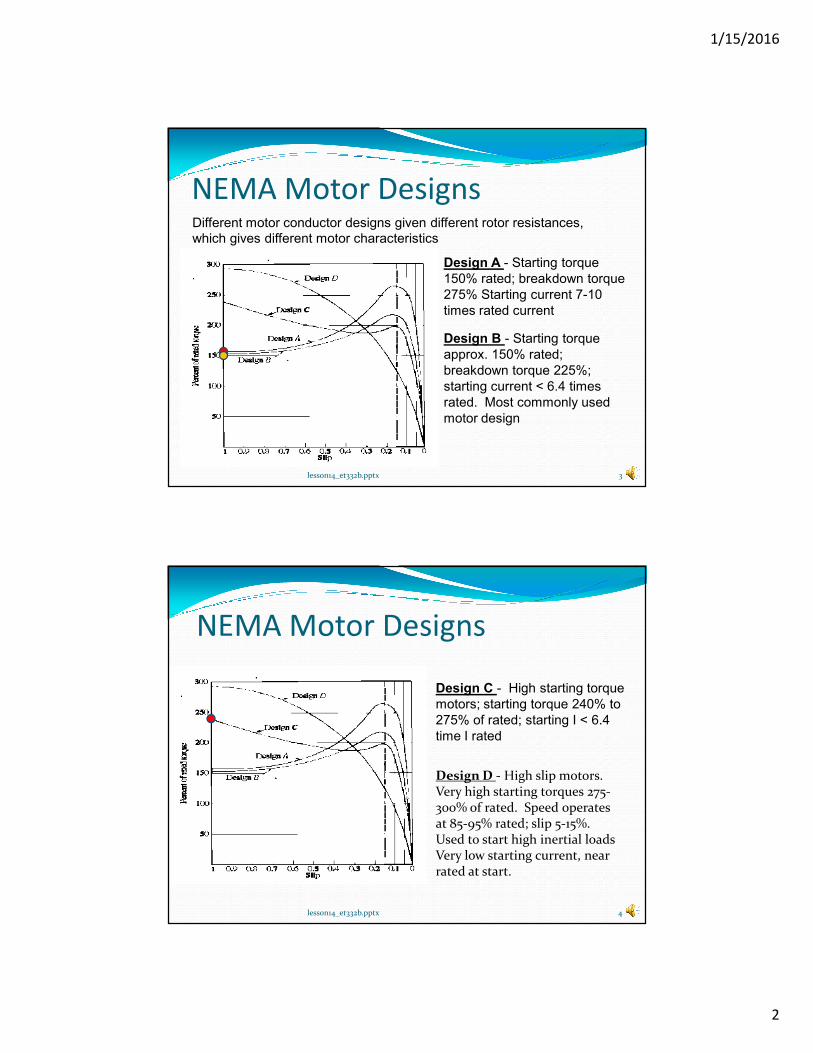
NEMA Motor DesignsDifferent motor conductor designs given different rotor resistances,
which gives different motor characteristics
3lesson14_et332b.pptx
Design A - Starting torque
150% rated; breakdown torque
275% Starting current 7-10
times rated current
Design B - Starting torque
approx. 150% rated;
breakdown torque 225%;
starting current < 6.4 times
rated. Most commonly used
motor design
lesson14_et332b.pptx 4
NEMA Motor Designs
Design C - High starting torque
motors; starting torque 240% to
275% of rated; starting I < 6.4
time I rated
Design D - High slip motors. Very high starting torques 275-300% of rated. Speed operates at 85-95% rated; slip 5-15%. Used to start high inertial loads Very low starting current, near rated at start.
1/15/2016
3
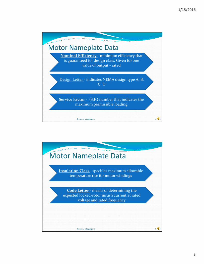
Motor Nameplate Data
lesson14_et332b.pptx 5
Nominal Efficiency - minimum efficiency that is guaranteed for design class. Given for one
value of output - rated
Design Letter - indicates NEMA design type A, B, C, D
Service Factor - (S.F.) number that indicates the maximum permissible loading
lesson14_et332b.pptx 6
Motor Nameplate Data
Insulation Class - specifies maximum allowable temperature rise for motor windings
Code Letter - means of determining the expected locked-rotor inrush current at rated
voltage and rated frequency
1/15/2016
4
lesson14_et332b.pptx 7
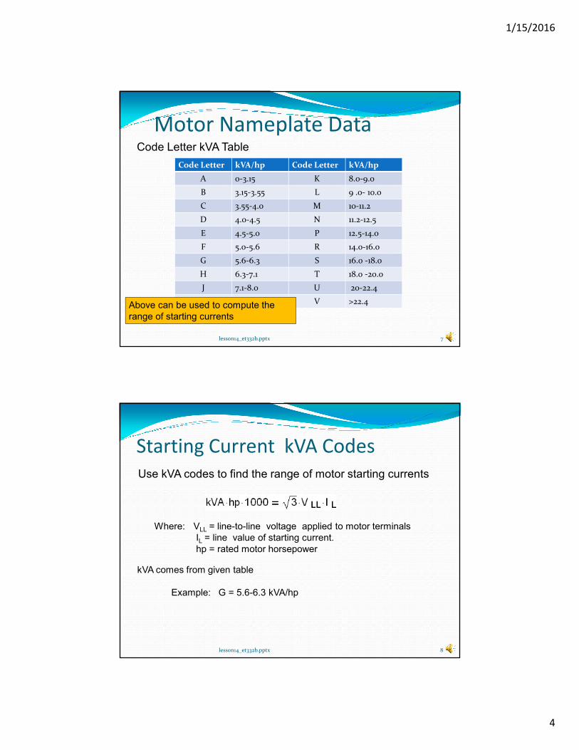
Motor Nameplate DataCode Letter kVA Table
Code Letter kVA/hp Code Letter kVA/hp
A 0-3.15 K 8.0-9.0
B 3.15-3.55 L 9 .0- 10.0
C 3.55-4.0 M 10-11.2
D 4.0-4.5 N 11.2-12.5
E 4.5-5.0 P 12.5-14.0
F 5.0-5.6 R 14.0-16.0
G 5.6-6.3 S 16.0 -18.0
H 6.3-7.1 T 18.0 -20.0
J 7.1-8.0 U 20-22.4
V >22.4Above can be used to compute the
range of starting currents
Starting Current kVA Codes
lesson14_et332b.pptx 8
Use kVA codes to find the range of motor starting currents
kVA comes from given table
Example: G = 5.6-6.3 kVA/hp
Where: VLL = line-to-line voltage applied to motor terminals
IL = line value of starting current.
hp = rated motor horsepower
1/15/2016
5
lesson14_et332b.pptx 9
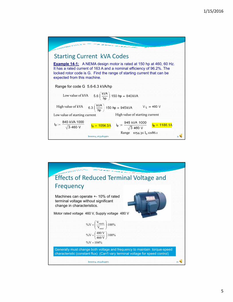
Starting Current kVA CodesExample 14-1: A NEMA design motor is rated at 150 hp at 460, 60 Hz.
It has a rated current of 163 A and a nominal efficiency of 96.2%. The
locked rotor code is G. Find the range of starting current that can be
expected from this machine.
Range for code G 5.6-6.3 kVA/hp
Low value of kVA
High value of kVA
Low value of starting current
Ilr840 kVA⋅ 1000⋅
3 460⋅ V⋅:= Ilr 1054.3=
High value of starting current
Range 1054.3≤ Ilr ≤1186.1
A A
Effects of Reduced Terminal Voltage and
Frequency
lesson14_et332b.pptx 10
Machines can operate +- 10% of rated
terminal voltage without significant
change in characteristics.
Motor rated voltage 460 V, Supply voltage 480 V
%104V%
%100V 460
V 480V%
%100V
VV%
rated
plysup
=
⋅
=
⋅
=
Generally must change both voltage and frequency to maintain torque-speed
characteristic (constant flux) (Can't vary terminal voltage for speed control)
1/15/2016
6
Effects of Changing Voltage and Frequency on
Torque
lesson14_et332b.pptx 11
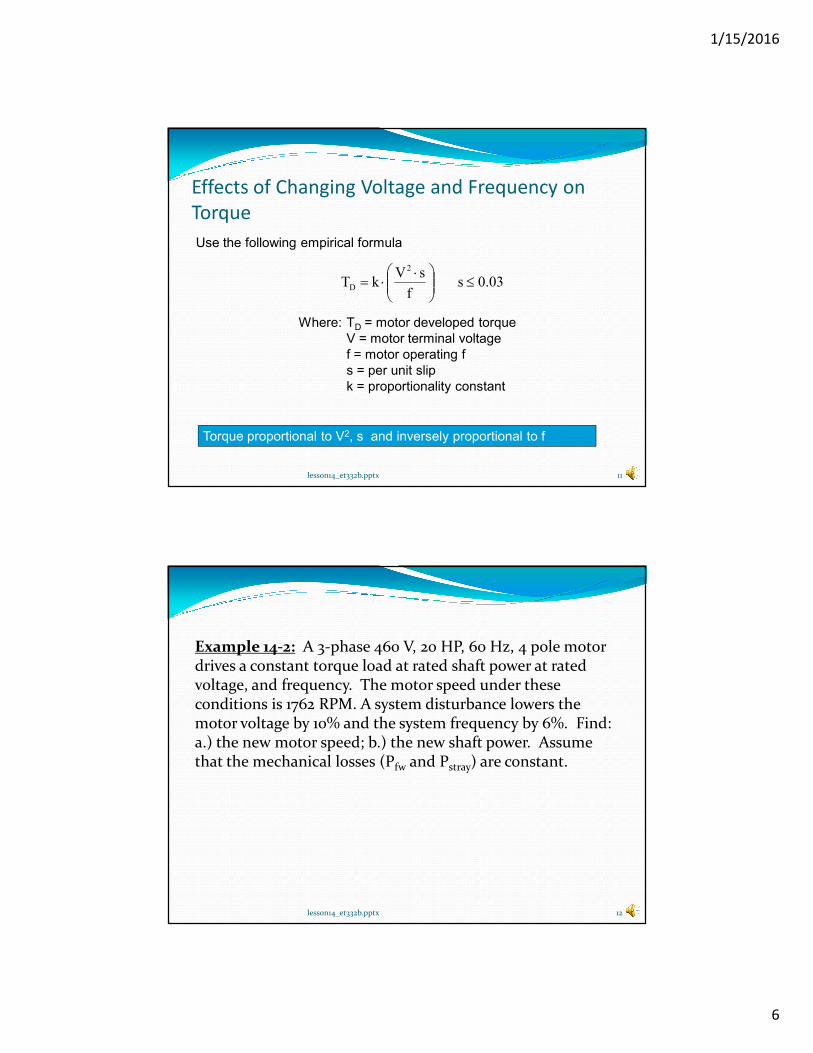
Use the following empirical formula
0.03s f
sVkT
2
D ≤
⋅⋅=
Where: TD = motor developed torque
V = motor terminal voltage
f = motor operating f
s = per unit slip
k = proportionality constant
Torque proportional to V2, s and inversely proportional to f
lesson14_et332b.pptx 12
Example 14-2: A 3-phase 460 V, 20 HP, 60 Hz, 4 pole motor drives a constant torque load at rated shaft power at rated voltage, and frequency. The motor speed under these conditions is 1762 RPM. A system disturbance lowers the motor voltage by 10% and the system frequency by 6%. Find: a.) the new motor speed; b.) the new shaft power. Assume that the mechanical losses (Pfw and Pstray) are constant.
1/15/2016
7
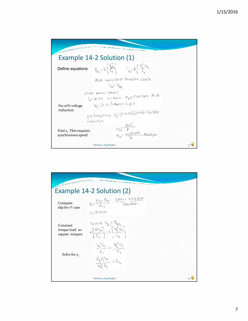
Example 14-2 Solution (1)
lesson14_et332b.pptx 13
Define equations
For 10% voltagereduction
Find s1. This requires synchronous speed
Example 14-2 Solution (2)
lesson14_et332b.pptx 14
Computeslip for 1st case
Constanttorque load soequate torques
Solve for s2
1/15/2016
8
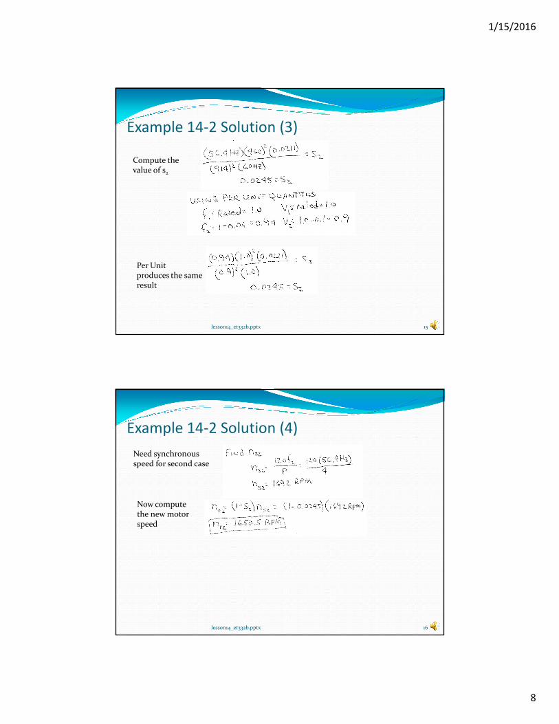
lesson14_et332b.pptx 15
Example 14-2 Solution (3)
Compute thevalue of s2
Per Unitproduces the sameresult
lesson14_et332b.pptx 16
Example 14-2 Solution (4)
Need synchronousspeed for second case
Now computethe new motorspeed
1/15/2016
9
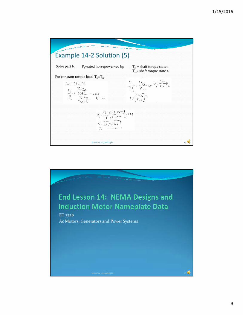
lesson14_et332b.pptx 17
Example 14-2 Solution (5)
Solve part b. P1=rated horsepower=20 hp Ts1 = shaft torque state 1Ts2= shaft torque state 2
For constant torque load Ts1=Ts2
ET 332b
Ac Motors, Generators and Power Systems
lesson14_et332b.pptx 18