Embed Size (px)
Citation preview

I I I /
I
EsTIMAToR'S PIPING MAN'HOUR MANUAL
/ F I F T H
I E D I T I 0 N
/
I /
I /
I /
I I
Man-Hour Manuals and Other Books by John S. Page
Conceptual Cost Estimating Manual
Cost Estimating Man-Hour Manual for Pipelines and Marine Structures
Estimator's Electrical Man-Hour Manualf3rd Edition
Estimator's Equipment Installation Man-Hour Manual/3rd Edition
Estimator's General Construction Man-Hour Manual/2nd Edition
Estimator's Man-Hour Manual on Heating, Air Conditioning, Ventilating, and Plumbing/2nd Edition
Estimator's Piping Man-Hour Manual/5th Edition
J o h n S. Page has wide experience in cost and labor estimat-
l l l /
l /
l / /
l ing, having worked for some of the largest construction finns in the world. He has made and assembled numerous types of esti- mates including lump-sum, hard-priced, and scope, and has conducted many time and method studies in the field and in fabricating shops. Mr. Page has a B.S. in civil engineering from the University of Arkansas and received the Award of Merit from the American Association of Cost Engineers in recogni- tion of outstanding service and cost engineering.
l / /
l l /
/ /
I / m PIPIN(
/ F I F T H
U E D I T I 0 N
I / / /
JOHN S. PAGE
I I
G P u Gulf Professional Publishing An Imprint of Elsevier
I
Estimator's Piping Man-Hour Manual Fifth Edition
Copyright �9 1958, 1967, 1976, 1987, 1999 by Butterworth- Heinemann. All rights reserved. Printed in the United States of America. This book, or parts thereof, may not be reproduced in any form without permission of the publisher.
Permi,ss4ons may be sought d~rectly from Elsevm~"s Science and Technology R~ghts Departrr~t in Oxford. UK Phone: (44) 1865 843830. Fax: (44) 1865 853333. e-mail: perm~ss=ons@elsevN~'.co.uk You may also complete your request on-hne via the Elsevmr homepa<3e: http://ww~v.e(sev~r.com by sekecbng "Customer Support" and then "Obta~mng Perm~s,s4ons'.
Originally Published by" Gulf Publishing Company An Impnnt of Elsevier Houston, TX
109
Library of Congress Cataloging-in Publication Data
Page. John S. Estimator's piping man-hour manual / John S. Page.-Sth ed.
p. cm. Includes bibliographical references and index. 1. Pipe-fitting-Estimates-United States. 2. Labor time.
TH6721.P3 1999 696'.2'0299-dc21
ISBN - 13" 978-0-88415-259-0 ISBN - ! 0" 0-884 ! 5-259-6
Printed on acid-free paper (00)
I.Title.
99-18583 CIP
For information, please contact: Manager of Special Sales Butterworth-Heinemann 225 Wildwood Avenue Woburn, MA 0 i 801-2041 Tel: 781-904-2500 Fax: 781-904-2620 For information on all Butterworth-Heinemann publications available, contact out World Wide Web home page at: http://www.bh.com
I / / / / / / / / / / / / /
I /
/ /
I /
I /
I / / / / / / / / /
C O N T E N T S
Preface, xi The Human Fac tor in Estimating, xi
Introduct ion, xii
S e c t i o n O n e - - - S H O P F A B R I C A T I O N OF P I P E A N D F I T T I N G S
Section In t roduct ion . . . . . . . . . . . . . . . . . . . . . . . . . . . . . . . . . . . . . . . . . . . . . . . . . 1 Shop Handling Scheduled Pipe for Fabr icat ion . . . . . . . . . . . . . . . . . . . . . . . . . . . . 2 Shop Handling Heavy Wall Pipe for Fabr icat ion . . . . . . . . . . . . . . . . . . . . . . . . . . . 3 Shop Handling Large O.D. Pipe for Fabr ica t ion . . . . . . . . . . . . . . . . . . . . . . . . . . . 4 Notes On Pipe Bends . . . . . . . . . . . . . . . . . . . . . . . . . . . . . . . . . . . . . . . . . . . . . . . . . 5 Standard Types of Bends . . . . . . . . . . . . . . . . . . . . . . . . . . . . . . . . . . . . . . . . . . . . . . 6 Pipe B e n d s - - S c h e d u l e 20 to 100 Inclusive . . . . . . . . . . . . . . . . . . . . . . . . . . . . . . . 7 Pipe B e n d s - - S c h e d u l e 120, 140 and 160 . . . . . . . . . . . . . . . . . . . . . . . . . . . . . . . . . 8 Pipe B e n d s - - H e a v y Wall- -45 ~ or Less . . . . . . . . . . . . . . . . . . . . . . . . . . . . . . . . . . . 9 Pipe B e n d s - - H e a v y Wal l - -Over 45 ~ to 90 ~ Inclusive . . . . . . . . . . . . . . . . . . . . . . . 10 Pipe B e n d s - - L a r g e O.D. Sizes . . . . . . . . . . . . . . . . . . . . . . . . . . . . . . . . . . . . . . . . . . 11 Attaching F l a n g e s - - S c r e w e d Type . . . . . . . . . . . . . . . . . . . . . . . . . . . . . . . . . . . . . . 12 Attaching F l a n g e s - - S c r e w e d Type . . . . . . . . . . . . . . . . . . . . . . . . . . . . . . . . . . . . . . 13 Attaching Flanges-- -Screwed Type . . . . . . . . . . . . . . . . . . . . . . . . . . . . . . . . . . . . . . 14 Attaching Flanges---Slip-On Type . . . . . . . . . . . . . . . . . . . . . . . . . . . . . . . . . . . . . . . 15 Attaching F langes- -S l ip -On Type . . . . . . . . . . . . . . . . . . . . . . . . . . . . . . . . . . . . . . . 16 Attaching F langes - -Weld Neck Type . . . . . . . . . . . . . . . . . . . . . . . . . . . . . . . . . . . . 17 Attaching Orifice Flanges---Slip-On and Threaded Types . . . . . . . . . . . . . . . . . . . . 18 Attaching Orifice F langes - -Weld Neck Type . . . . . . . . . . . . . . . . . . . . . . . . . . . . . . 19 General Welding Notes . . . . . . . . . . . . . . . . . . . . . . . . . . . . . . . . . . . . . . . . . . . . . . . 20 Butt We lds - - l ne r t Gas Shielded Root Pass . . . . . . . . . . . . . . . . . . . . . . . . . . . . . . . 21 Machine Butt Welds . . . . . . . . . . . . . . . . . . . . . . . . . . . . . . . . . . . . . . . . . . . . . . . . . . 22 Manual Butt Welds---Scheduled . . . . . . . . . . . . . . . . . . . . . . . . . . . . . . . . . . . . . . . . 23 Manual Heavy Wall Butt Welds . . . . . . . . . . . . . . . . . . . . . . . . . . . . . . . . . . . . . . . . . 24 Manual Large O.D. Butt Welds . . . . . . . . . . . . . . . . . . . . . . . . . . . . . . . . . . . . . . . . . 25 90 ~ Welded Nozzles . . . . . . . . . . . . . . . . . . . . . . . . . . . . . . . . . . . . . . . . . . . . . . . . . . 26 90 ~ Welded Nozzles---Reinforced . . . . . . . . . . . . . . . . . . . . . . . . . . . . . . . . . . . . . . . 27 Large O.D. 90 ~ Nozzle Welds . . . . . . . . . . . . . . . . . . . . . . . . . . . . . . . . . . . . . . . . . . . 28 Large O.D. 90 ~ Nozzle Welds - -Re in fo rced . . . . . . . . . . . . . . . . . . . . . . . . . . . . . . . . 28 45 ~ Welded Nozzles . . . . . . . . . . . . . . . . . . . . . . . . . . . . . . . . . . . . . . . . . . . . . . . . . . 29 45 ~ Welded Nozzles---Reinforced . . . . . . . . . . . . . . . . . . . . . . . . . . . . . . . . . . . . . . . 30 Large O.D. 45 ~ Nozzle Welds . . . . . . . . . . . . . . . . . . . . . . . . . . . . . . . . . . . . . . . . . . . 31 Large O.D. 45 ~ Nozzle Welds - -Re in fo rced . . . . . . . . . . . . . . . . . . . . . . . . . . . . . . . . 31 Concentr ic Swedged Ends . . . . . . . . . . . . . . . . . . . . . . . . . . . . . . . . . . . . . . . . . . . . 32 Eccentr ic Swedged Ends . . . . . . . . . . . . . . . . . . . . . . . . . . . . . . . . . . . . . . . . . . . . . . 33 End C l o s u r e s - - P r e s s u r e Type . . . . . . . . . . . . . . . . . . . . . . . . . . . . . . . . . . . . . . . . . . 34 Heavy Wall End C l o s u r e - - P r e s s u r e Type . . . . . . . . . . . . . . . . . . . . . . . . . . . . . . . . . 35 Large O.D. Pipe End C l o s u r e s - - P r e s s u r e Type . . . . . . . . . . . . . . . . . . . . . . . . . . . . 36 90 ~ Coupling Welds and Socket Welds . . . . . . . . . . . . . . . . . . . . . . . . . . . . . . . . . . . 37 'Olet Type Welds . . . . . . . . . . . . . . . . . . . . . . . . . . . . . . . . . . . . . . . . . . . . . . . . . . . . . 38
Flame Cutting P ipe - -Schedu led . . . . . . . . . . . . . . . . . . . . . . . . . . . . . . . . . . . . . . . . 39 Flame Cutting P ipe - -Heavy Wall . . . . . . . . . . . . . . . . . . . . . . . . . . . . . . . . . . . . . . . 40 Flame Cutting P ipe- -Large O.D. Sizes . . . . . . . . . . . . . . . . . . . . . . . . . . . . . . . . . . . 41 Machine Cutting Pipe---Scheduled . . . . . . . . . . . . . . . . . . . . . . . . . . . . . . . . . . . . . . 42 Machine Cutting P ipe - -Heavy Wall . . . . . . . . . . . . . . . . . . . . . . . . . . . . . . . . . . . . . 43 Machine Cutting P ipe - -Large O.D. Sizes . . . . . . . . . . . . . . . . . . . . . . . . . . . . . . . . . 44 Flame Beveling Pipe--- ' l m Type . . . . . . . . . . . . . . . . . . . . . . . . . . . . . . . . . . . . . . . . 45 Machine Beveling Pipe--- 'U ~ Type, ~V" Type and Double Angle . . . . . . . . . . . . . . . 46 Beveling Heavy Wall Pipe . . . . . . . . . . . . . . . . . . . . . . . . . . . . . . . . . . . . . . . . . . . . . 47 Beveling Large O.D. Pipe . . . . . . . . . . . . . . . . . . . . . . . . . . . . . . . . . . . . . . . . . . . . . . 48 Threading P ipe- - Inc lud ing Cut . . . . . . . . . . . . . . . . . . . . . . . . . . . . . . . . . . . . . . . . . 49 Welded Carbon Steel At tachments . . . . . . . . . . . . . . . . . . . . . . . . . . . . . . . . . . . . . . 50 Drilling Holes in Welded At tachments . . . . . . . . . . . . . . . . . . . . . . . . . . . . . . . . . . . 50 Machining Inside of Pipe . . . . . . . . . . . . . . . . . . . . . . . . . . . . . . . . . . . . . . . . . . . . . . 51 Machining Inside of Large O.D. Pipe . . . . . . . . . . . . . . . . . . . . . . . . . . . . . . . . . . . . 52 Boring Inside Diameter of Pipe and Installing Straightening Vanes . . . . . . . . . . . . 53 Installing Flow Nozzles . . . . . . . . . . . . . . . . . . . . . . . . . . . . . . . . . . . . . . . . . . . . . . . 54 Preheat ing Butt Welds and Any Type Flange Welds . . . . . . . . . . . . . . . . . . . . . . . . 55 Preheat ing Heavy Wall Pipe Butt Welds . . . . . . . . . . . . . . . . . . . . . . . . . . . . . . . . . . 56 Preheat ing Large O.D. Pipe Butt Welds . . . . . . . . . . . . . . . . . . . . . . . . . . . . . . . . . . 57 Preheat ing 90 ~ Nozzle Welds . . . . . . . . . . . . . . . . . . . . . . . . . . . . . . . . . . . . . . . . . . . 58 Preheat ing Large O.D. 90 ~ Nozzle Welds . . . . . . . . . . . . . . . . . . . . . . . . . . . . . . . . . 59 Local Stress Rel iev ing- -Scheduled . . . . . . . . . . . . . . . . . . . . . . . . . . . . . . . . . . . . . . 60 Local Stress Rel ieving--Heavy Wall . . . . . . . . . . . . . . . . . . . . . . . . . . . . . . . . . . . . . 61 Local Stress Rel ieving--Large O.D. Sizes . . . . . . . . . . . . . . . . . . . . . . . . . . . . . . . . . 62 Full Furnace Stress Relieving and Heating Trea tment . . . . . . . . . . . . . . . . . . . . . . 63 Radiographic In spec t ion - -Schedu led . . . . . . . . . . . . . . . . . . . . . . . . . . . . . . . . . . . 64 Radiographic Inspec t ion - -Heavy Wall . . . . . . . . . . . . . . . . . . . . . . . . . . . . . . . . . . . 65 Radiographic Inspec t ion- -Large O.D. Sizes . . . . . . . . . . . . . . . . . . . . . . . . . . . . . . . 66 Magnetic or Dye Penet ran t Inspect ion of Welded Joints . . . . . . . . . . . . . . . . . . . . 67 Magnetic or Dye Penet ran t Inspect ion of Welded Joints . . . . . . . . . . . . . . . . . . . . 68 Testing Fabr ica ted Assemblies---Flanged Ends . . . . . . . . . . . . . . . . . . . . . . . . . . . . 69 Testing Fabr ica ted Assemblies---Plain or Beveled Ends . . . . . . . . . . . . . . . . . . . . . 70 Testing Fabr ica ted Assembl i e s - -Heavy Wall . . . . . . . . . . . . . . . . . . . . . . . . . . . . . . 71 Access Holes . . . . . . . . . . . . . . . . . . . . . . . . . . . . . . . . . . . . . . . . . . . . . . . . . . . . . . . 72 Miscel laneous Fabricat ion Opera t ions . . . . . . . . . . . . . . . . . . . . . . . . . . . . . . . . . . . 73 Man Hours Per Foot of Cylindrical Coil Fabricat ion Bending Only . . . . . . . . . . . . 74
S e c t i o n Two F I E L D F A B R I C A T I O N A N D E R E C T I O N
Section Int roduct ion . . . . . . . . . . . . . . . . . . . . . . . . . . . . . . . . . . . . . . . . . . . . . . . . . 75 Handling and Erect ing Straight Run Pipe---Scheduled . . . . . . . . . . . . . . . . . . . . . . 76 Handling and Erect ing Straight Run P ipe - -Heavy Wall . . . . . . . . . . . . . . . . . . . . . 77 Handling and Erect ing Straight Run P ipe - -Large O.D. Size . . . . . . . . . . . . . . . . . . 78 Handling and Erect ing Fabr ica ted Spool P i ece s - -Schedu l ed . . . . . . . . . . . . . . . . 79 Handling and Erect ing Fabr ica ted Spool P i eces - -Heavy Wall . . . . . . . . . . . . . . . . 80 Handling and Erect ing Fabr icated Spool P i eces - -La rge O.D. Sizes . . . . . . . . . . . 81 Making on Screwed Fittings and Valves . . . . . . . . . . . . . . . . . . . . . . . . . . . . . . . . . . 82 Field Handling Valves . . . . . . . . . . . . . . . . . . . . . . . . . . . . . . . . . . . . . . . . . . . . . . . . 83 Field Erect ion Bolt-Ups . . . . . . . . . . . . . . . . . . . . . . . . . . . . . . . . . . . . . . . . . . . . . . . 84 Attaching F l a n g e s - - S c r e w e d Type . . . . . . . . . . . . . . . . . . . . . . . . . . . . . . . . . . . . . . 85 Attaching F l a n g e s - - S c r e w e d Type . . . . . . . . . . . . . . . . . . . . . . . . . . . . . . . . . . . . . . 86
/ / / / / / / /
l l / / / /
l /

/ / / / / / / /
l / /
l / / / /
Attaching F l a n g e s - - S c r e w e d Type . . . . . . . . . . . . . . . . . . . . . . . . . . . . . . . . . . . . . . 87 Attaching F langes- -S l ip -On Type . . . . . . . . . . . . . . . . . . . . . . . . . . . . . . . . . . . . . . . 88 Attaching F langes - -Weld Neck Type . . . . . . . . . . . . . . . . . . . . . . . . . . . . . . . . . . . . 89 Attaching Orifice Flanges---Slip-On and Threaded Types . . . . . . . . . . . . . . . . . . . . 90 Attaching Orifice F langes - -Weld Neck Type . . . . . . . . . . . . . . . . . . . . . . . . . . . . . . 91 General Welding Notes . . . . . . . . . . . . . . . . . . . . . . . . . . . . . . . . . . . . . . . . . . . . . . . 92 Manual Butt Welds - -Schedu le . . . . . . . . . . . . . . . . . . . . . . . . . . . . . . . . . . . . . . . . . 93 Manual Butt Welds - -Heavy Wall . . . . . . . . . . . . . . . . . . . . . . . . . . . . . . . . . . . . . . . . 94 Manual Butt Welds - -Large O.D. Sizes . . . . . . . . . . . . . . . . . . . . . . . . . . . . . . . . . . . 95 90 ~ Welded Nozzles . . . . . . . . . . . . . . . . . . . . . . . . . . . . . . . . . . . . . . . . . . . . . . . . . . 96 90 ~ Welded Nozz les - -Re in fo rced . . . . . . . . . . . . . . . . . . . . . . . . . . . . . . . . . . . . . . . 97 Large O.D. 90 ~ Nozzle Welds . . . . . . . . . . . . . . . . . . . . . . . . . . . . . . . . . . . . . . . . . . . 98 Large O.D. 90 ~ Nozzle Welds - -Re inforced . . . . . . . . . . . . . . . . . . . . . . . . . . . . . . . . 98 45 ~ Welded Nozzles . . . . . . . . . . . . . . . . . . . . . . . . . . . . . . . . . . . . . . . . . . . . . . . . . . 99 45 ~ Welded Nozz les - -Re in fo rced . . . . . . . . . . . . . . . . . . . . . . . . . . . . . . . . . . . . . . . 100 Large O.D. 45 ~ Nozzle Welds . . . . . . . . . . . . . . . . . . . . . . . . . . . . . . . . . . . . . . . . . . . 101 Large O.D. 45 ~ Nozzle Welds - -Re inforced . . . . . . . . . . . . . . . . . . . . . . . . . . . . . . . . 101 Concentr ic Swedged Ends . . . . . . . . . . . . . . . . . . . . . . . . . . . . . . . . . . . . . . . . . . . . 102 Eccentr ic Swedged Ends . . . . . . . . . . . . . . . . . . . . . . . . . . . . . . . . . . . . . . . . . . . . . . 103 End C l o s u r e s - - P r e s s u r e Type . . . . . . . . . . . . . . . . . . . . . . . . . . . . . . . . . . . . . . . . . . 104 Heavy Wall End C l o s u r e s - - P r e s s u r e Type . . . . . . . . . . . . . . . . . . . . . . . . . . . . . . . . 105 Large O.D. Pipe End C l o s u r e s - - P r e s s u r e Type . . . . . . . . . . . . . . . . . . . . . . . . . . . . 106 90 ~ Coupling Welds and Socket Welds . . . . . . . . . . . . . . . . . . . . . . . . . . . . . . . . . . . 107 'Olet Type Welds . . . . . . . . . . . . . . . . . . . . . . . . . . . . . . . . . . . . . . . . . . . . . . . . . . . . . 108 Flame Cutting P i p e - - S c h e d u l e d . . . . . . . . . . . . . . . . . . . . . . . . . . . . . . . . . . . . . . . . 109 Flame Cutting P i p e - - H e a v y Wall . . . . . . . . . . . . . . . . . . . . . . . . . . . . . . . . . . . . . . . 110 Flame Cutting Pipe---Large O.D. Sizes . . . . . . . . . . . . . . . . . . . . . . . . . . . . . . . . . . . 111 Flame Beveling Pipe--- 'V ~ Type . . . . . . . . . . . . . . . . . . . . . . . . . . . . . . . . . . . . . . . . 112 Flame Beveling P ipe - -La rge O.D. Sizes . . . . . . . . . . . . . . . . . . . . . . . . . . . . . . . . . . 113 Threading Pipe---Including Cut . . . . . . . . . . . . . . . . . . . . . . . . . . . . . . . . . . . . . . . . . 114 Welded Carbon Steel At tachments . . . . . . . . . . . . . . . . . . . . . . . . . . . . . . . . . . . . . . 115 Drilling Holes in Welded At tachments . . . . . . . . . . . . . . . . . . . . . . . . . . . . . . . . . . . 116 Machining Inside of Pipe . . . . . . . . . . . . . . . . . . . . . . . . . . . . . . . . . . . . . . . . . . . . . . 117 Machining Inside of Large O.D. Pipe . . . . . . . . . . . . . . . . . . . . . . . . . . . . . . . . . . . . 118 Boring Inside Diameter of Pipe and Installing Straightening Vanes . . . . . . . . . . . . 119 Installing Flow Nozz les - -Hold ing Ring Type . . . . . . . . . . . . . . . . . . . . . . . . . . . . . . 120 Preheat ing Butt Welds and Any Type Flange Welds . . . . . . . . . . . . . . . . . . . . . . . . 121 Preheat ing Heavy Wall Pipe Butt Welds . . . . . . . . . . . . . . . . . . . . . . . . . . . . . . . . . . 122 Preheat ing Large O.D. Pipe Butt Welds . . . . . . . . . . . . . . . . . . . . . . . . . . . . . . . . . . 123 Preheat ing 90 ~ Nozzle Welds . . . . . . . . . . . . . . . . . . . . . . . . . . . . . . . . . . . . . . . . . . . 124 Preheat ing Large O.D. 90 ~ Nozzle Welds . . . . . . . . . . . . . . . . . . . . . . . . . . . . . . . . . 125 Local Stress Relieving---Scheduled . . . . . . . . . . . . . . . . . . . . . . . . . . . . . . . . . . . . . . 126 Local Stress Rel iev ing- -Heavy Wall . . . . . . . . . . . . . . . . . . . . . . . . . . . . . . . . . . . . . 127 Local Stress Rel ieving--Large O.D. Sizes . . . . . . . . . . . . . . . . . . . . . . . . . . . . . . . . . 128 Radiographic Inspect ion-- -Scheduled . . . . . . . . . . . . . . . . . . . . . . . . . . . . . . . . . . . 129 Radiographic In spec t i onmHeavy Wall . . . . . . . . . . . . . . . . . . . . . . . . . . . . . . . . . . . 130 Radiographic In spec t ion - -La rge O.D. Sizes . . . . . . . . . . . . . . . . . . . . . . . . . . . . . . . 131 Hydrostat ic Tes t ing - -Schedu led . . . . . . . . . . . . . . . . . . . . . . . . . . . . . . . . . . . . . . . . 132 Hydrostat ic Tes t ing- -Heavy Wall . . . . . . . . . . . . . . . . . . . . . . . . . . . . . . . . . . . . . . . 133 Hydrostat ic Tes t ingmLarge O.D. Sizes . . . . . . . . . . . . . . . . . . . . . . . . . . . . . . . . . . . 134 Access Holes . . . . . . . . . . . . . . . . . . . . . . . . . . . . . . . . . . . . . . . . . . . . . . . . . . . . . . . 135 Ins t rument and Control Piping . . . . . . . . . . . . . . . . . . . . . . . . . . . . . . . . . . . . . . . . . 136 Soldered Non-Ferrous Fittings . . . . . . . . . . . . . . . . . . . . . . . . . . . . . . . . . . . . . . . . . 136
vii
PVC-Plastic Pipe . . . . . . . . . . . . . . . . . . . . . . . . . . . . . . . . . . . . . . . . . . . . . . . . . . . . . 137 Saran Lined Steel Pipe and Fittings . . . . . . . . . . . . . . . . . . . . . . . . . . . . . . . . . . . . . 138 Schedule 30 or 40 Rubber-Lined Steel Pipe and Fittings . . . . . . . . . . . . . . . . . . . . . 139 Schedule 40 Lead IAned Steel Pipe and Fittings . . . . . . . . . . . . . . . . . . . . . . . . . . . 140 Flanged Cast Iron Cement IAned Pipe and Fittings . . . . . . . . . . . . . . . . . . . . . . . . . 141 Schedule 40 Cement Lined Carbon Steel Pipe with Standard Fittings . . . . . . . . . . 142 Double Tough Pyrex Pipe and Fittings . . . . . . . . . . . . . . . . . . . . . . . . . . . . . . . . . . . 143 Overhead Transite Pressure P ipe- -Class 1 50 . . . . . . . . . . . . . . . . . . . . . . . . . . . . . 144
S e c t i o n T h r e e - - - A L L O Y A N D N O N - F E R R O U S F A B R I C A T I O N
Section Introduct ion . . . . . . . . . . . . . . . . . . . . . . . . . . . . . . . . . . . . . . . . . . . . . . . . . 145 Shop Handling Pipe for Fabricat ion . . . . . . . . . . . . . . . . . . . . . . . . . . . . . . . . . . . . . 146 Handle and Erect Fabricated Spool Pieces . . . . . . . . . . . . . . . . . . . . . . . . . . . . . . . 147 Handle and Erect Straight Run Pipe . . . . . . . . . . . . . . . . . . . . . . . . . . . . . . . . . . . . . 148 Pipe Bends . . . . . . . . . . . . . . . . . . . . . . . . . . . . . . . . . . . . . . . . . . . . . . . . . . . . . . . . . 149 Attaching Flanges . . . . . . . . . . . . . . . . . . . . . . . . . . . . . . . . . . . . . . . . . . . . . . . . . . . 150 Make-Ons through 12-in. Handle Valves through 42-in . . . . . . . . . . . . . . . . . . . . . . . 151 Field Erect ion Bolt-Ups . . . . . . . . . . . . . . . . . . . . . . . . . . . . . . . . . . . . . . . . . . . . . . . 153 All Welded Fabricat ion . . . . . . . . . . . . . . . . . . . . . . . . . . . . . . . . . . . . . . . . . . . . . . . 154 Flame Cutting or Beveling . . . . . . . . . . . . . . . . . . . . . . . . . . . . . . . . . . . . . . . . . . . . . 155 Machine Cutting and Beveling Pipe . . . . . . . . . . . . . . . . . . . . . . . . . . . . . . . . . . . . . 156 Threading Pipe . . . . . . . . . . . . . . . . . . . . . . . . . . . . . . . . . . . . . . . . . . . . . . . . . . . . . . 157 Welded At tachments and Drilling Holes in Welded Attachments . . . . . . . . . . . . . . 158 Local Stress Relieving . . . . . . . . . . . . . . . . . . . . . . . . . . . . . . . . . . . . . . . . . . . . . . . . 159 Radiographic Inspection . . . . . . . . . . . . . . . . . . . . . . . . . . . . . . . . . . . . . . . . . . . . . . 160 Magnetic or Dye Penetrant Inspection . . . . . . . . . . . . . . . . . . . . . . . . . . . . . . . . . . . 161 Hydrostat ic Testing . . . . . . . . . . . . . . . . . . . . . . . . . . . . . . . . . . . . . . . . . . . . . . . . . . 162 Access Holes . . . . . . . . . . . . . . . . . . . . . . . . . . . . . . . . . . . . . . . . . . . . . . . . . . . . . . . 163
S e c t i o n F o u r - - P N E U M A T I C M E C H A N I C A L
I N S T R U M E N T A T I O N
Section Introduct ion . . . . . . . . . . . . . . . . . . . . . . . . . . . . . . . . . . . . . . . . . . . . . . . . . 164 Liquid Level Gauge Glasses---Transparent Type . . . . . . . . . . . . . . . . . . . . . . . . . . . 165 Liquid Level Gauge Glasses - -Transparen t Type . . . . . . . . . . . . . . . . . . . . . . . . . . . 166 Liquid Level Gauge Glasses - -Transparen t Type . . . . . . . . . . . . . . . . . . . . . . . . . . . 167 Liquid Level Gauge Glasses---Transparent Type . . . . . . . . . . . . . . . . . . . . . . . . . . . 168 Liquid Level Gauge Glasses---Reflex Type . . . . . . . . . . . . . . . . . . . . . . . . . . . . . . . . 169 Liquid Level Gauge Glasses - -Ref lex Type . . . . . . . . . . . . . . . . . . . . . . . . . . . . . . . . 170 Liquid Level Gauge Glasses---Reflex Type . . . . . . . . . . . . . . . . . . . . . . . . . . . . . . . . 171 Liquid Level Gauge Glasses---Reflex Type . . . . . . . . . . . . . . . . . . . . . . . . . . . . . . . . 172 Pressure Gauges . . . . . . . . . . . . . . . . . . . . . . . . . . . . . . . . . . . . . . . . . . . . . . . . . . . . . 173 Pneumat ic Liquid Level Instruments---Local Mounted . . . . . . . . . . . . . . . . . . . . . . 174 Pneumat ic Liquid Level Ins t ruments - -Loca l Mounted . . . . . . . . . . . . . . . . . . . . . . 175 Pneumat ic Pressure Ins txuments- -Local Mounted . . . . . . . . . . . . . . . . . . . . . . . . . 176 Pneumat ic Temperature Ins t ruments - -Loca l Mounted . . . . . . . . . . . . . . . . . . . . . 177 Thermomete r s and ThermoweUs . . . . . . . . . . . . . . . . . . . . . . . . . . . . . . . . . . . . . . . 178 Thermomete r s and Thermowel ls . . . . . . . . . . . . . . . . . . . . . . . . . . . . . . . . . . . . . . . 179
viii
l l l / / / / / / / / / / / /
l
l /
l / / / / / / / /
l / /
l /
T h e r m o w e U s and T h e r m o c o u p l e s . . . . . . . . . . . . . . . . . . . . . . . . . . . . . . . . . . . . . . 180 Relief Valves- - -Screwed . . . . . . . . . . . . . . . . . . . . . . . . . . . . . . . . . . . . . . . . . . . . . . . 181 Relief Valves---Flanged . . . . . . . . . . . . . . . . . . . . . . . . . . . . . . . . . . . . . . . . . . . . . . . 182 Relief Valves-- -Flanged . . . . . . . . . . . . . . . . . . . . . . . . . . . . . . . . . . . . . . . . . . . . . . . 183 Pneuma t i c F low Transmi t t e r s . . . . . . . . . . . . . . . . . . . . . . . . . . . . . . . . . . . . . . . . . . 184 Flow Indicat ing Transmi t te rs , F low Reco rde r s and Flow Cont ro l l e r s . . . . . . . . . . 185 Pneumat i c Liquid Level Transmi t t e r s . . . . . . . . . . . . . . . . . . . . . . . . . . . . . . . . . . . . 186 Contro l Panel Ins ta l la t ion . . . . . . . . . . . . . . . . . . . . . . . . . . . . . . . . . . . . . . . . . . . . . 187 Connec t ing Pneumat i c Panel Board In s t rumen t s . . . . . . . . . . . . . . . . . . . . . . . . . . 188 Connec t ing Pneumat i c Panel Board In s t rumen t s . . . . . . . . . . . . . . . . . . . . . . . . . . 189
S e c t i o n F i v e - - U N D E R G R O U N D P I P I N G
Sect ion In t roduc t ion . . . . . . . . . . . . . . . . . . . . . . . . . . . . . . . . . . . . . . . . . . . . . . . . . 190 Machine Excava t ion . . . . . . . . . . . . . . . . . . . . . . . . . . . . . . . . . . . . . . . . . . . . . . . . . 191 Hand Excava t ion . . . . . . . . . . . . . . . . . . . . . . . . . . . . . . . . . . . . . . . . . . . . . . . . . . . . 192 Rock Excava t ion . . . . . . . . . . . . . . . . . . . . . . . . . . . . . . . . . . . . . . . . . . . . . . . . . . . . 193 Shor ing and Bracing Trenches . . . . . . . . . . . . . . . . . . . . . . . . . . . . . . . . . . . . . . . . . 193 Disposal of Excava t ed Material . . . . . . . . . . . . . . . . . . . . . . . . . . . . . . . . . . . . . . . . 194 Backf'dling and Tamping . . . . . . . . . . . . . . . . . . . . . . . . . . . . . . . . . . . . . . . . . . . . . . 195 U n d e r g r o u n d 150 Lbs. B. & S. Cast Iron Pipe . . . . . . . . . . . . . . . . . . . . . . . . . . . . . 195 U n d e r g r o u n d Vitrified Clay and Conc re t e Pipe . . . . . . . . . . . . . . . . . . . . . . . . . . . . 196 Socke t C lamps for Cast Iron Pipe . . . . . . . . . . . . . . . . . . . . . . . . . . . . . . . . . . . . . . . 197 Pipe Coa ted with Tar and Field Wrapped by Machine . . . . . . . . . . . . . . . . . . . . . . 197
S e c t i o n S i x - - H A N G E R S A N D S U P P O R T S
Sect ion In t roduc t ion . . . . . . . . . . . . . . . . . . . . . . . . . . . . . . . . . . . . . . . . . . . . . . . . . 198 Hangers and Suppor t s . . . . . . . . . . . . . . . . . . . . . . . . . . . . . . . . . . . . . . . . . . . . . . . . 199
S e c t i o n S e v e n - - P A I N T I N G
Sect ion In t roduc t ion . . . . . . . . . . . . . . . . . . . . . . . . . . . . . . . . . . . . . . . . . . . . . . . . . 200 Surface Area of Pipe for Paint ing . . . . . . . . . . . . . . . . . . . . . . . . . . . . . . . . . . . . . . . 201 Sand Blast and Paint Pipe . . . . . . . . . . . . . . . . . . . . . . . . . . . . . . . . . . . . . . . . . . . . . 202
S e c t i o n E i g h t - - P A T E N T S C A F F O L D I N G
Sect ion In t roduc t ion . . . . . . . . . . . . . . . . . . . . . . . . . . . . . . . . . . . . . . . . . . . . . . . . . 203 Erec t and Dismant le . . . . . . . . . . . . . . . . . . . . . . . . . . . . . . . . . . . . . . . . . . . . . . . . . 204
S e c t i o n N i n e - - - I N S U I ~ T I O N
Sect ion In t roduc t ion . . . . . . . . . . . . . . . . . . . . . . . . . . . . . . . . . . . . . . . . . . . . . . . . . 205 Indoor The rma l Type . . . . . . . . . . . . . . . . . . . . . . . . . . . . . . . . . . . . . . . . . . . . . . . . . 206 I n s u l a t i o n - - H o t Pipe . . . . . . . . . . . . . . . . . . . . . . . . . . . . . . . . . . . . . . . . . . . . . . . . . 207
Ix
S e c t i o n T e n - - - S A M P L E E S T I M A T E
Sect ion In t roduc t ion . . . . . . . . . . . . . . . . . . . . . . . . . . . . . . . . . . . . . . . . . . . . . . . . . 208 Sample Job Es t imate Fo rm . . . . . . . . . . . . . . . . . . . . . . . . . . . . . . . . . . . . . . . . . . . . 209 Shop F a b r i c a t i o n - - C a r b o n Steel . . . . . . . . . . . . . . . . . . . . . . . . . . . . . . . . . . . . . . . 210 Shop F a b r i c a t i o n - - A l l o y . . . . . . . . . . . . . . . . . . . . . . . . . . . . . . . . . . . . . . . . . . . . . . 211 Field Erec t - - -Shop Fabr ica ted Piping . . . . . . . . . . . . . . . . . . . . . . . . . . . . . . . . . . . . 211 Field Fabr i ca t e and E r e c t - - S c r e w e d . . . . . . . . . . . . . . . . . . . . . . . . . . . . . . . . . . . . 212 Field Fabr i ca t e and E r e c t - - W e l d e d . . . . . . . . . . . . . . . . . . . . . . . . . . . . . . . . . . . . . 213 Erec t V a l v e s - - S c r e w e d and F langed . . . . . . . . . . . . . . . . . . . . . . . . . . . . . . . . . . . . 214 Hangers and Suppor t s . . . . . . . . . . . . . . . . . . . . . . . . . . . . . . . . . . . . . . . . . . . . . . . . 215 Sandb las t and Paint Pipe . . . . . . . . . . . . . . . . . . . . . . . . . . . . . . . . . . . . . . . . . . . . . . 215 Insula t ion . . . . . . . . . . . . . . . . . . . . . . . . . . . . . . . . . . . . . . . . . . . . . . . . . . . . . . . . . . 215 Hand E x c a v a t e . . . . . . . . . . . . . . . . . . . . . . . . . . . . . . . . . . . . . . . . . . . . . . . . . . . . . . 215 U n d e r g r o u n d Piping . . . . . . . . . . . . . . . . . . . . . . . . . . . . . . . . . . . . . . . . . . . . . . . . . . 215 Es t ima te S u m m a r y . . . . . . . . . . . . . . . . . . . . . . . . . . . . . . . . . . . . . . . . . . . . . . . . . . . 216
S e c t i o n E l e v e n - - - T E C H N I C A L I N F O R M A T I O N
Sect ion In t roduc t ion . . . . . . . . . . . . . . . . . . . . . . . . . . . . . . . . . . . . . . . . . . . . . . . . . 217 C i r c u m f e r e n c e of Pipe for Comput ing Welding Material . . . . . . . . . . . . . . . . . . . . 218 C i r c u m f e r e n c e of Pipe for Comput ing Welding M a t e r i a l - - H e a v y Wall . . . . . . . . . 219 C i r c u m f e r e n c e of Pipe for Comput ing Welding Ma te r i a l - -La rge O.D. Sizes . . . . . 220 Weights of Piping M a t e r i a l s - - G e n e r a l Notes . . . . . . . . . . . . . . . . . . . . . . . . . . . . . . 221 Weights of Piping Mater ia l s - - - l " . . . . . . . . . . . . . . . . . . . . . . . . . . . . . . . . . . . . . . . . 222 Weights of Piping Mater ials---I � 8 8 . . . . . . . . . . . . . . . . . . . . . . . . . . . . . . . . . . . . . . 223 Weights of Piping M a t e r i a l s - - 1 W ' . . . . . . . . . . . . . . . . . . . . . . . . . . . . . . . . . . . . . . . 224 Weights of Piping Materials---2" . . . . . . . . . . . . . . . . . . . . . . . . . . . . . . . . . . . . . . . . 225 Weights of Piping Materials---2~A " . . . . . . . . . . . . . . . . . . . . . . . . . . . . . . . . . . . . . . . 226 Weights of Piping Materials---3" . . . . . . . . . . . . . . . . . . . . . . . . . . . . . . . . . . . . . . . . 227 Weights of Piping Ma te r i a l s - - -3~" . . . . . . . . . . . . . . . . . . . . . . . . . . . . . . . . . . . . . . . 228 Weights of Piping Ma te r i a l s - -4 " . . . . . . . . . . . . . . . . . . . . . . . . . . . . . . . . . . . . . . . . 229 Weights of Piping Materials---5" . . . . . . . . . . . . . . . . . . . . . . . . . . . . . . . . . . . . . . . . 230 Weights of Piping Materials---6" . . . . . . . . . . . . . . . . . . . . . . . . . . . . . . . . . . . . . . . . 231 Weights of Piping Materials---8" . . . . . . . . . . . . . . . . . . . . . . . . . . . . . . . . . . . . . . . . 232 Weights of Piping Materials---10" . . . . . . . . . . . . . . . . . . . . . . . . . . . . . . . . . . . . . . . 233 Weights of Piping Materials---12" . . . . . . . . . . . . . . . . . . . . . . . . . . . . . . . . . . . . . . . 234 Weights of Piping Ma te r i a l s - -14" . . . . . . . . . . . . . . . . . . . . . . . . . . . . . . . . . . . . . . . 235 Weights of Piping Ma te r i a l s - -16" . . . . . . . . . . . . . . . . . . . . . . . . . . . . . . . . . . . . . . . 236 Weights of Piping Ma te r i a l s - -18" . . . . . . . . . . . . . . . . . . . . . . . . . . . . . . . . . . . . . . . 237 Weights of Piping Ma te r i a l s - -20" . . . . . . . . . . . . . . . . . . . . . . . . . . . . . . . . . . . . . . . 238 Weights of Piping Materials---24" . . . . . . . . . . . . . . . . . . . . . . . . . . . . . . . . . . . . . . . 239 Hanger Load C a l c u l a t i o n s - - G e n e r a l Notes . . . . . . . . . . . . . . . . . . . . . . . . . . . . . . . 240 Hanger Diagram . . . . . . . . . . . . . . . . . . . . . . . . . . . . . . . . . . . . . . . . . . . . . . . . . . . . . 241 Table of Weights . . . . . . . . . . . . . . . . . . . . . . . . . . . . . . . . . . . . . . . . . . . . . . . . . . . . . 241 Hange r Load Calcula t ions . . . . . . . . . . . . . . . . . . . . . . . . . . . . . . . . . . . . . . . . . . . . . 241 Minutes to Decimal Hours - - -Convers ion Table . . . . . . . . . . . . . . . . . . . . . . . . . . . . 248
I I / /
I I I /
I /
l l / /
I I
/
/
/ /
l /
/
l / / / /
/
/ /
/
P R E F A C E
Updated with the addition of 26 new tables on pneumatic mechanical instrumentation, this fifth edition is written for the majority of estimators who have not had the advan- tages of years of experience and/or of being associated with a firm that spends thou- sands of dollars for time studies and research analyses. I believe that the book will decrease the chance of errors and help the partially experienced estimator to deter- mine more accurately the actual direct labor cost for the complete fabrication and installation of process piping for a given industrial or chemical plant.
This book is strictly for estimating direct labor in man hours only. You will not find any costs for materials, equipment usage, warehousing and storing, fabricating, shop set- up, or overhead. These costs can be readily obtained by a good estimator who can visualize and consider job schedule, size, and location. If a material take-off is avail- able, this cost can be obtained from vendors who will furnish the materials. These items must be considered for each individual job.
The following direct man hours (or in the case of alloy and nonferrous materials, the per- centages) were determined by gathering hundreds of time and method studies coupled with actual cost of various operations, both in the shop and field on many piping jobs located throughout the country, ranging in cost from $1,000,000 to $5,000,000. By careful- ly analyzing these many reports, I established an average productivity rate of 70%. The man hours or percentages compiled throughout this manual are based on this percentage.
I wish to call your attention to the introduction on the following pages entitled "Pro- duction and Composite Rate," which is the key to this method of estimating.
The Human Factor in Estimating
In this high-tech world of sophisticated software packages, including several for labor and cost estimating, you might wonder what a collection of man-hour tables offers that a computer program does not. The answer is the human factor. In preparing a complete estimate for a refinery, petrochemical, or other heavy industrial project one often con- fronts 12-18 major accounts, and each account has 5--100 or more sub-accounts, depend- ing on the project and its engineering design. While it would seem that such numerous variables provide the perfect opportunity for computerized algorithmic solution, accu- rate, cost-effective, realistic estimating is still largely a function of human insight and expertise. Each project has unique aspects that still require the seasoned consideration of an experienced professional, such as general economy, projects supervision, labor relations, job conditions, construction equipment, and weather, to name a few.
Computers are wonderful tools. They can solve problems as no human can, but I do not believe construction estimating is their fort6. I have reviewed several construction estimating software packages and have yet to fmd one that I would completely rely on. Construction estimating is an art, a science, and a craft, and I recommend that it be done by those who understand and appreciate all three of these facets. This manual is intended for those individuals.
John Page Houston, Texas
xi

{ { {
INTRODUCTION Production and Composite Rate
This is the golden key that unlocks the gate to the wealth of p ~ pipe estimating informa- tion that follows. The most impo~t area to be considered before calculating labor dollars is productivity efficiency. This is a must if the many man-hour tables that follow are to be cor- rectly applied. Productivity efficiency in conjunction with the production elements must be con- sidered for each individual project.
I have found after comparing many projects that production percentages can be classified into five categories and the production elements can be grouped into six different classifications. The six different classes of production elements are:
1. General economy 2. Project supervision 3. Labor relations 4. Job conditions 5. Equipment 6. Weather
The five ranges of productivity efficiency percentages are:
Type Percentage Range
1. Very Low 10-40 2. Low 41-60 3. Average 61-80 4. Very Good 81-90 5. Excellent 91-100
Although you may agree with the ranges described here, you may still wonder with such a wide percentage range how to determine a definite percentage. To illustrate how simply this is done we will evaluate each of the six elements and give an example with each.
I. GENERAL ECONOMY
This is simply the state of the nation or area in which your project is to be developed. Things that should be evaluated under this category are:
xU
{ { { { { { { { { { { {
/ /
/
/ /
/
I / / / / /
/
/
1 /
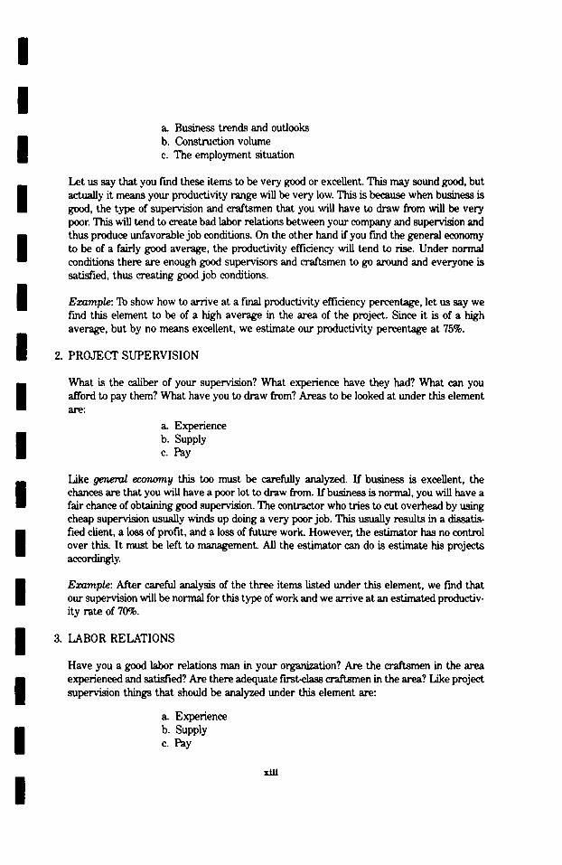
a_ Business trends and outlooks b. Construction volume c. The employment situation
Let us say that you find these items to be very good or excellent. This may sound good, but actually it means your productivity range will be very low. This is because when business is good, the type of supervision and craftsmen that you will have to draw from will be very poor. This will tend to create bad labor relations between your company and supervision and thus produce unfavorable job conditions. On the other hand if you fred the general economy to be of a fairly good average, the productivity efficiency will tend to rise. Under normal conditions there are enough good supervisors and craftsmen to go around and everyone is satisfied, thus creating good job conditions.
Example: To show how to arrive at a final productivity efficiency percentage, let us say we fred this element to be of a high average in the area of the project. Since it is of a high average, but by no means excellent, we estimate our productivity percentage at 75%.
2. PROJEC'r SUPERVISION
What is the caliber of your supervision? What experience have they had? What can you afford to pay them? What have you to draw from? Areas to be looked at under this element are:
a. Experience b. Supply c. Pay
Like genera/economy this too must be c a m p y analyzed. If business is excellent, the chances are that you will have a poor lot to draw from. If business is normal, you will have a fair chance of obtaining good supervision. The contractor who tries to cut overhead by using cheap supervision usually winds up doing a very poor job. This usually results in a dissatis- fied client, a loss of profit, and a loss of future worL However, the estimator has no control over this. It must be left to management. All the estimator can do is estimate his projects accordingly.
Example: Mter careful analysis of the three items listed under this element, we fred that our supervision will be normal for this type of work and we arrive at an estimated productiv- ity rate of 70%.
3. LABOR RELATIONS
Have you a good labor relations man in your organization? Are the craflzmen in the area experienced and satisfied? Are there adequate f'wst•lass craRsmen in the area? Like project supervision things that should be analyzed under this element are:
a. Experience b. Supply c. Pay
xUl

/
The area where your project is to be constructed should be checked to see if the proper experienced craftsmen are available locally or if you will have to rely on travelers to fill your needs. Can and will your organization pay the prevailing wage rates?
Example: Let us say that for a project in a given area we have found our labor relations to be fair but feel that they could be a little better. Since this is the case, we arrive at an effi- ciency rating of 65% for this element.
4. JOB CONDITIONS
What is the scope of the work and just what is involved in the job? Is the schedule fight or do you have ample time to complete the project? What is the condition of the site? Is it high and dry and easy to drain or is it low and muddy and hard to drain? Will you be working around a plant already in production? Will there be fie-ins making it necessary to shut down various systems of the plant? What will be the relationship between production personnel and con- struction personnel? Will most of your operations be manual or mechanized? What kind of material pmcm~ment will you have? There are many items that could be considered here, dependent on the project; however, we feel that the most important of these items that should be analyzed under this element are as follows:
a. Scope of work b. Site conditions c. Material procurement d. Manual and mechanized operations
By careful study and analysis of the plans and specifications coupled with a site visitation you should be able to correctly estimate a productivity efficiency percentage for this item.
Example: Let us say that the project we are estimating is a completely new plant and that we have ample time to complete the project but the site location is low and muddy. There- fore, after evaluation we estimate a productivity rating of only 60%.
5. EQUIPMENT
Do you have ample equipment to do your job? What kind of shape is it in? Will you have good maintenance and repair help? The main items to study under this element are:
a. Usability b. Condition c. Maintenance and repair
This should be the simplest of all elements to analyze. Every estimator should know what type and kind of equipment his company has as well as what kind of mechanical shape it is in.
Example: Let us assume that our company equipment is in very good shape, that we have an ample supply to draw from, and that we have average mechanics. Since this is the case we estimate a productivity percentage of 70%.
xiv
/
I 1 1
1 /
/ / / /
/
/
1 /
1
1 1 I 1 1 1 1 1 1 I 1 1 1 1 1
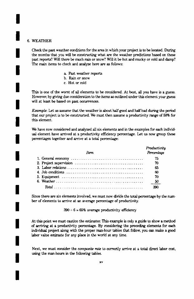
6. WEATHER
Check the past weather conditions for the area in which your project is to be located. During the months that you will be constructing what are the weather predictions based on these past reports? Will there be much rain or snow? Will it be hot and mucky or cold and damp? The main items to check and analyze here are as follows:
& Past weather reports b. Rain or snow c. Hot or cold
This is one of the worst of all elements to be considered. At best, all you have is a guess. However, by giving due consideration to the items as outlined under this element your guess will at least be based on past occttrrences.
Example: Let us assume that the weather is about half good and half bad during the period that our project is to be constructed. We must then assume a productivity range of 50% for this element.
We have now considered and analyzed all six elements and in the examples for each individ- ual element have arrived at a productivity efficiency percentage. Let us now group these percentages together and arrive at a total percentage:
Item
I. General economy . . . . . . . . . . . . . . . . . . . . . . . . . . . . . . . . . . . . . . .
2. Project supervision ..................................... 3. Lair relations ......................................... 4. Job conditions .......................................... 5. Equipment ............................................ 6. Weather ...............................................
Tota~ ................................................
Productivity Percentage
75 70 65 60 70 50
Since there are six elements involved, we must now divide the total percentage by the num- ber of elements to arrive at an average percentage of productivity.
390 + 6 = 65% average productivity efficiency
At this point we must caution the estimator. This example is only a guide to show a method of arriving at a productivity percentage. By considering the preceding elements for each individual project along with the proper man-hour tables that follow, you can make a good labor value estimate for any place in the world at any time.
Next, we must consider the cumpos~ rate to correctly arrive at a total direct labor cost, using the man-hours in the following tables.
IV
1
/
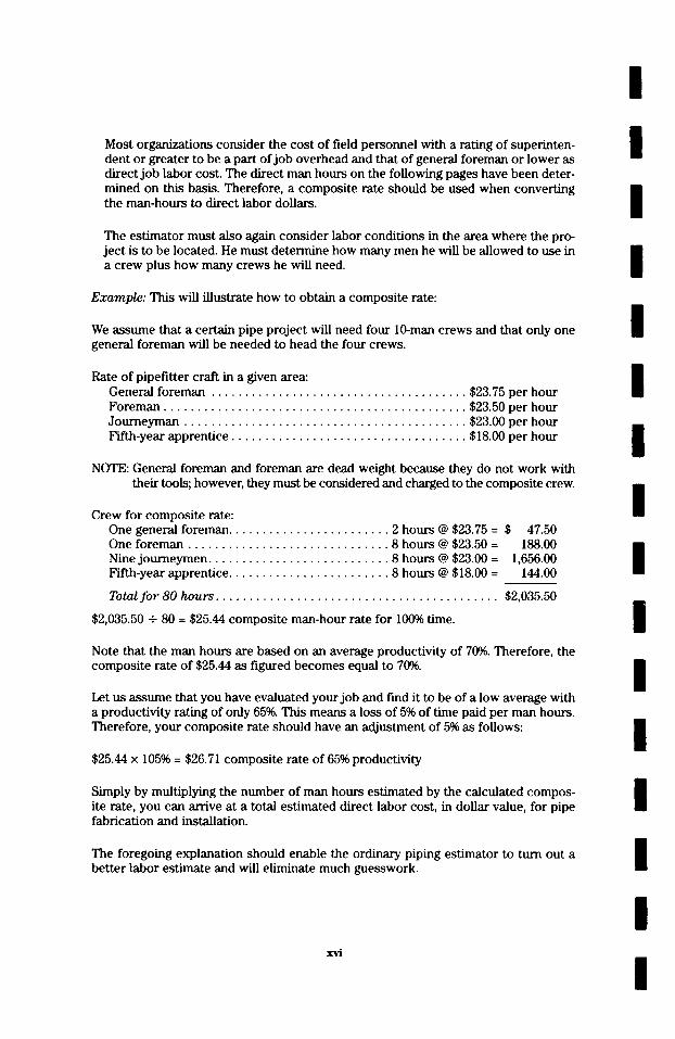
Most organizations consider the cost of field personnel with a rating of superinten- dent or greater to be a part of job overhead and that of general foreman or lower as direct job labor cost. The direct man hours on the following pages have been deter- mined on this basis. Therefore, a composite rate should be used when converting the man-hours to direct labor dollars.
The est imator must also again consider labor conditions in the area where the pro- ject is to be located. He must determine how many men he will be allowed to use in a crew plus how many crews he will need.
E x a m p l e : This will illustrate how to obtain a composite rate:
We assume that a certain pipe project will need four 10-man crews and that only one general foreman will be needed to head the four crews.
Rate of pipefitter craft in a given area: General foreman . . . . . . . . . . . . . . . . . . . . . . . . . . . . . . . . . . . . . . $23.75 per hour Foreman . . . . . . . . . . . . . . . . . . . . . . . . . . . . . . . . . . . . . . . . . . . . . $23.50 per hour Journeyman . . . . . . . . . . . . . . . . . . . . . . . . . . . . . . . . . . . . . . . . . . $23.00 per hour Fifth-year apprentice . . . . . . . . . . . . . . . . . . . . . . . . . . . . . . . . . . . $18.00 per hour
NOTE: General foreman and foreman are dead weight because they do not work with their tools; however, they must be considered and charged to the composite crew.
Crew for composite rate: One general foreman . . . . . . . . . . . . . . . . . . . . . . . . 2 hours @ $23.75 = $ One foreman . . . . . . . . . . . . . . . . . . . . . . . . . . . . . . 8 hours @ $23.50 = Nine journeymen . . . . . . . . . . . . . . . . . . . . . . . . . . . 8 hours @ $23.00 = Fifth-year apprentice . . . . . . . . . . . . . . . . . . . . . . . . 8 hours @ $18.00 =
47.50 188.00
1,656.00 144.00
Total f o r 80 hours . . . . . . . . . . . . . . . . . . . . . . . . . . . . . . . . . . . . . . . . . . $2,035.50
$2,035.50 + 80 = $25.44 composite man-hour rate for 10(}% time.
Note that the man hours are based on an average productivity of 7096. Therefore, the composi te rate of $25.44 as figured becomes equal to 70%.
Let us assume that you have evaluated your job and find it to be of a low average with a productivity rating of only 65%. This means a loss of 5% of time paid per man hom,s. Therefore, your composite rate should have an adjustment of 5% as follows:
$25.44 x 10⁵% - $26.71 composite rate of 65% productivity
Simply by multiplying the number of man hours estimated by the calculated compos- ite rate, you can arrive at a total estimated direct labor cost, in dollar value, for pipe fabrication and installation.
The foregoing explanation should enable the ordinary piping estimator to turn out a bet ter labor estimate and will eliminate much guesswork.
xvi
/
/
I /
I
I
I / / /
/
/
/ /
/
/
/
/
/
/
/ /
S e c t i o n O n e
S H O P F A B R I C A T I O N
O F P I P E A N D F I T T I N G S
/
/
l / /
/
/ /
/
It is the intent and e x p r e s s pu rpose of this s e c - tion to cover as nea r ly as poss ib le al l opera t ions which may be encountered in a shop engaged in the p re fab r i ca t ion of p r o c e s s piping for any type of indus t r i a l o r chemica l plant .
The man hours l is ted for the va r ious opera t ions a r e for labor only, and have no bea r ing on ma- t e r i a l s which must be added in all c a s e s for a comple te labor and m a t e r i a l e s t ima te .
All labor for unloading f rom r a i l r o a d c a r s on t rucks , s to r ing in fabr ica t ion y a r d or warehouse , hauling to fabr ica t ion a r e a , fabr ica t ing and r e - turning to s to rage a r e a or loading for de l ivery to e rec t ion s i te have been given due c o n s i d e r a - tion in the man hours l is ted. No consideration has been g~ven to overhead or prof i t in any way.
For alloy and n o n - f e r r o u s fabr ica t ion , apply the p e r c e n t a g e s which appear under Section Three to the following pages l i s t ing the va r ious shop fabr ica t ion opera t ions .
I
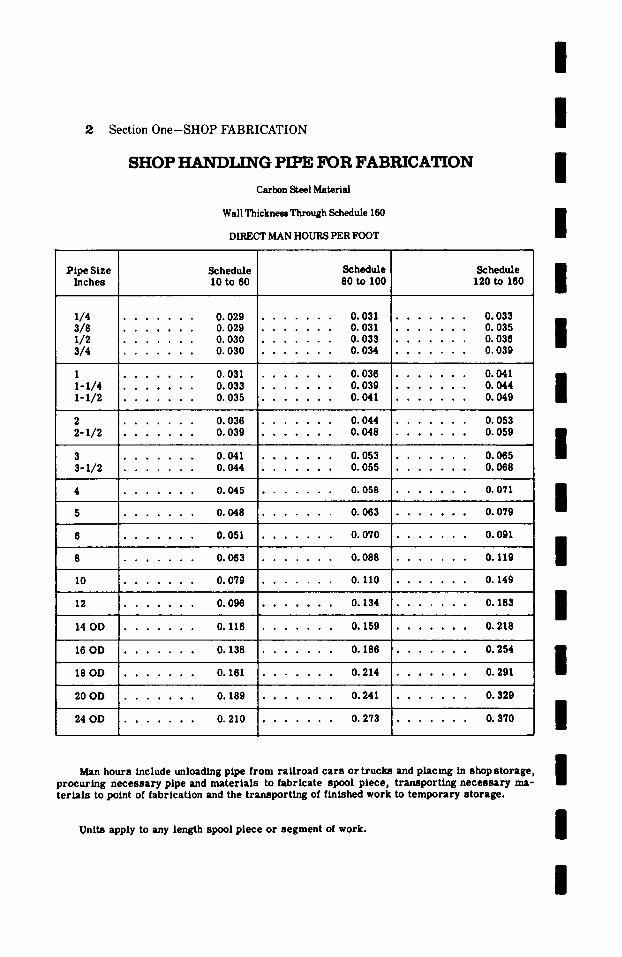
2 Section One-SHOP FABRICATION
S H O P H A N D L r N G PIPE FOR F A B R I C A T I O N
Carbon Steel Material
Wall Thickness Through Schedule 160
DIRECT MAN H O U R S PER FOOT
/
/
/ P i p e Size
I n c h e s
~/4 3/8 1 / 2 3/4
1 I-i/4 i - i /2
2 2-1/2
3 3 - I / 2
S c h e d u l e I 0 to 60
. . . . . . . 0 . 0 2 9
. . . . . . . O. 029
. . . . . . . O. 030
. . . . . . . O. 030
. . . . . . . 0 . 0 3 1
. . . . . . . 0 . 0 3 3
. . . . . . . 0. 035
. . . . . . . 0. 036
. . . . . . . 0 . 0 3 9
. . . . . . . 0 . 0 4 1
. . . . . . . 0. 044
S c h e d u l e 80 to I00
. . . . . . . O. 031
. . . . . . . O. 031
. . . . . . . O. 033
. . . . . . . O. 034
. . . . . . . 0. 036
. . . . . . . 0 . 0 3 9
. . . . . . . 0 . 0 4 1
. . . . . . . 0 . 0 4 4
. . . . . . . 0 . 0 4 8
. . . . . . . 0. 053
. . . . . . . 0. 055
S c h e d u l e 120 to 160
. . . . . . . O. 033
. . . . . . . 0 . 0 3 5
. . . . . . . O. 036
. . . . . . . 0 . 0 3 9
. . . . . . . 0 . 0 4 1
. . . . . . . O. 044
. . . . . . . 0 . 0 4 9
O. 053 . . . . . , .
O. 059
. . . . . . . 0 . 0 6 5
. . . . . . . 0. 068
4 . . . . . . . 0. 045 . . . . . . . 0. 058 . . . . . . . 0. 071
5 . . . . . . . 0. 048 . . . . . . . 0. 063 . . . . . . . 0. 079
6 . . . . . . . 0. 051 . . . . . . . 0. 070 . . . . . . . 0. 091
8 . . . . . . . 0. 063 . . . . . . . 0. 088 . . . . . . . 0. 119
10 . . . . . . . 0. 079 . . . . . . . 0. 110 . . . . . . . 0. 149
12 . . . . . . . 0. 096 . . . . . . . 0. 134 . . . . . . . 0. 183
14 O D . . . . . . . 0. 116 . . . . . . . 0. 159 . . . . . . . 0. 218
16 O D . . . . . . . 0. 138 . . . . . . . 0. 186 . . . . . . . 0. 254
18 O D . . . . . . . 0. 161 . . . . . . . 0. 214 . . . . . . . 0. 291
20 O D . . . . . . . 0. 189 . . . . . . . 0. 241 . . . . . . . 0. 329
24 O D . . . . . . . 0. 210 . . . . . . . 0. 273 . . . . . . . 0. 370
/
/
/
/ / / /
/
/ M a n h o u r s i n c l u d e u n l o a d i n g p i p e f r o m r a i l r o a d c a r s o r t r u c k s a n d p l a c i n g in s h o p s t o r a g e ,
p r o c u r i n g n e c e s s a r y p i p e a n d m a t e r i a l s to f a b r i c a t e s p o o l p i e c e , t r a n s p o r t i n g n e c e s s a r y m a - t e r i a l s to p o i n t of f a b r i c a t i o n a n d the t r a n s p o r t i n g of f i n i s h e d w o r k to t e m p o r a r y s t o r a g e .
U n i t s a p p l y to a n y l e n g t h s p o o l p i e c e o r s e g m e n t of w o r k .
/
/
/
/ / /
I /
Section One-SHOP FABRICATION 3
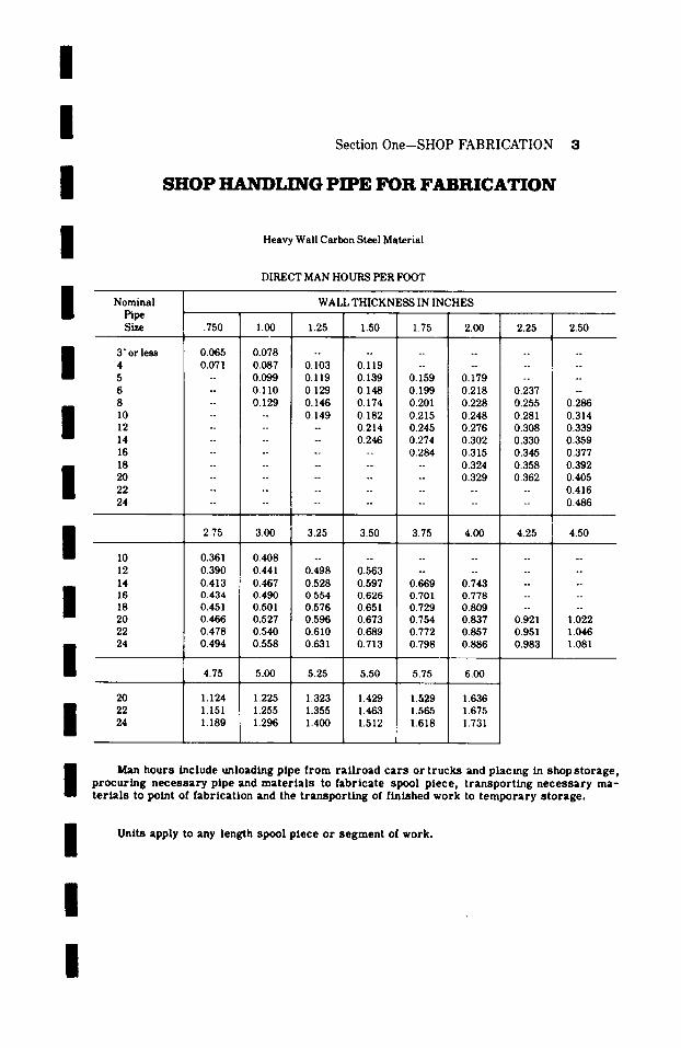
SHOP HANDLING PIPE FOR F A B R I C A T I O N
Heavy Wall Carbon Steel Material
DIRECT MAN HOURS PER FOOT
Nominal WALL THICKNESS IN INCHES Pipe Size .750 1.00 1.25 1.50 1.75 2.00 2.25 2.50
3" or less 0.065 0.078 . . . . . . . . . . . . 4 0.071 0.087 0.103 0.119 . . . . . . . . 5 -- 0.099 0.119 0.139 0.159 0.179 . . . . 6 -- 0.110 0.129 0.148 0.199 0.218 0.237 -- 8 -- 0.129 0.146 0.174 0.201 0.228 0.255 0.286
I I0 . . . . 0.149 0.182 0.215 0.248 0.281 0.314 12 . . . . . . 0.214 0.245 0.276 0.308 0.339 14 . . . . . . 0.246 0.274 0.302 0.330 0.359 16 . . . . . . . . 0.284 0.315 0.345 0.377 18 . . . . . . . . . . 0.324 0.358 0.392 20 . . . . . . . . . . 0.329 0.362 0.405 22 . . . . . . . . . . . . . . 0.416 24 . . . . . . . . . . . . . . 0.486
2.75 3.00 3.25 3.50 3.75 4.00 4.25 4.50
10 0.361 0.408 . . . . . . . . . . . . 12 0.390 0.441 0.498 0.563 . . . . . . . . 14 0.413 0.467 0.528 0.597 0.669 0.743 . . . .
I 16 0.434 0.490 0.554 0.626 0.701 0.778 . . . . 18 0.451 0.501 0.576 0.651 0.729 0.809 . . . . 20 0.466 0.527 0.596 0.673 0.754 0.837 0.921 1.022 22 0.478 0.540 0.610 0.689 0.772 0.857 0.951 1.046 24 0.494 0.558 0.631 0.713 0.798 0.886 0.983 1.081
I 4.75 5.00 5.25 5.50 5.75 6.00
20 1.124 1.225 1.323 1.429 1.529 1.636 22 1.151 1.255 1.355 1.463 1.565 1.675 24 1.189 1.296 1.400 1.512 1.618 1.731
I Man h o u r s inc lude un load ing p ipe f r o m r a i l r o a d c a r s or t r u c k s and p l a c i n g in shop s t o r a g e , p r o c u r i n g n e c e s s a r y p ipe and m a t e r i a l s to f a b r i c a t e spoo l p i e c e , t r a n s p o r t i n g n e c e s s a r y m a - t e r i a l s to po in t of f a b r i c a t i o n and the t r a n s p o r t i n g of f i n i shed w o r k to t e m p o r a r y s t o r a g e .
I [
Uni ts app ly to any l eng th spoo l p i e c e o r s e g m e n t of work .
/

I
4 Section One-SHOP FABRICATION
SHOP HANDLING PIPE FOR FABRICATION
Large O.D. Sizes Carbon Steel Material
DIRECT MAN HOURS PER FOOT
O.D. PIPE
INCHES 26 28 30 32 34 36 38 40 42 44 46 48 54 60
26 28 30 32 34 36
26 28 30 32 34 36
WALL THICKNESS IN INCHES .50O
Or Less .750 1.00 1.25 1.50 1.75 2.00 2.25 0.222 0.234 0.270 0.285 0.303 0.360 0.376 0.410 0.251 0.264 0.290 0.322 0.352 0.380 0.410 0.440 0.268 0.282 0.307 0.338 0.363 0.403 0.451 0.490 0.286 0.301 0.334 0.364 0.402 0.434 0.469 0.502 0.304 0.320 0.352 0.387 0.427 0.461 0.502 0.534 0.336 0.354 0.386 0.421 0.453 0.503 0.563 0.610 0.353 0.372 0.407 0.445 0.479 0.532 0.593 0.642 0.372 0.392 0.428 0.468 0.504 0.560 0.624 0.676 0.405 0.426 0.464 0.506 0.543 0.603 0.675 -- 0.422 0.444 0.484 0.528 0.568 0.634 0.708 -- 0.442 0.465 0.506 0.552 0.593 0.662 0.741 -- 0.473 0.498 0.543 0.592 0.633 0.703 0.780 -- 0.542 0.570 0.621 0.677 0.723 0.803 0.891 -- 0.610 0.642 0.700 0.763 0.813 0.902 1.001 --
2.50 2.75 3.00 3.25 3.50 3.75 4.00 4.25 0.446 0.514 0.570 0.640 0.720 0.808 0.900 0.993 0.453 0.521 0.580 0.650 0.726 0.819 0.910 1.000 0.505 0.530 0.588 0.658 0.734 0.830 0.927 1.020 0.517 0.543 0.595 0.670 0.740 0.842 0.940 1.041 0.550 0.578 0.607 0.690 0.750 0.860 0.954 1.073 0.628 0.659 0.692 0.734 0.778 0.877 0.970 1.105
4.50 4.75 5.00 5.25 5.50 5.75 6.00 1.100 1.194 1.305 1.410 1.520 1.630 1.751 1.120 1.244 1.370 1.453 1.570 1.695 1.810 1.135 1.299 1.440 1.480 1.600 1.765 1.880 1.170 1.359 1.480 1.520 1.660 1.830 1.960 1.204 1.400 1.520 1.570 1.690 1.855 1.995 1.233 1.480 1.560 1.600 1.740 1.895 2.100
Man h o u r s inc lude un load ing p ipe f r o m r a i l r o a d c a r s or t r u c k s and p l ac ing in shop s t o r a g e , p r o c u r i n g n e c e s s a r y p ipe and m a t e r i a l s to f a b r i c a t e spool p i ece , t r a n s p o r t i n g n e c e s s a r y m a - t e r i a l s to point of f a b r i c a t i o n and the t r a n s p o r t i n g of f in i shed work to t e m p o r a r y s t o r a g e .
Uni ts apply to any length spool p i ece o r s e g m e n t of work.
I I I I I I I / / /
/
/
/
/
/

I
I I
I
I
Section One-SHOP FABRICATION 5
NOTES ON PIPE BENDS
Minimum Bending Radii: Man hours shown for pipe bends are based upon a minimum bending radii of 5 nominal pipe size diameters, with the exception oflarge sizes and/or lighter walls which must be bent on longer rsdii. For bends having a radius of less than 5 diameters add 50~ to man hours shown.
Welding Long Bends: When it is n e c e s s a r y to weld together two or more p ieces of pipe to produce the length requ i red in the pipe bend, add the man hours for welding.
I Compotmd Bends: Man hours of pipe bends o ther than the s tandard types i l lus t ra ted or with bends in more than one plane a r e obtained by adding together the man hours of the com- ponent bends that a r e combined to produce the compound bend.
I / / /
I I /
Bends Without Tangents: For Pipe Bends (Sch. 160 and less) o r d e r e d without tangents , add 15c~ to man hours shown.
Bends With LongArcs: For pipe bending with an arc exceeding 10 feet; add 100% to the bending man hours shown for each additional 10 feet ofarc or part thereof.
Connecting Tangents: No. 5 Offset Bends and No. 7 U-Bends a r e to be cons idered as such only when the bends a re continuous a r c s or li the tangent between a r c s of the s a m e radius is 1 ' - 0 " long or less . If the tangent between a r c s is longer than 1 ' - 0 " , the bends should be cons idered as compound bends, i. e . , double angle bends, double qua r t e r bends, etc.
No. 9 Expansion U-Bends a re to be cons idered as such only when the bends a r e continuous a r c s or if the tangents between the "IT" and the 90 ~ bends, of the s ame radius a r e 1 ' - 0 " or less . When such tangents a r e longer than 1 ' - 0 " the bends should be man houred as one "U" and two 90 ~ Pipe Bends. Bends f rom 181 ~ to 359 ~ should be man houred at the s ame man hours as a No. 11 Bend.
Offset Bends: No. 5 Offset Bends a r e cons idered as such only when each angle is 90 ~ or less and the connecting tangents between a r c s a r e within the maximum of 1 ' - 0 " specif ied in the preceding note.
Beveled Ends: If Pipe Bends a r e to have the ends beveled for welding add the man hours for beveling.
Thread Ends: If Pipe Bends a r e to have the ends threaded only, add the man hours for threading.
Flcmged Ends: If Pipe Bends a r e to have the ends fitted with sc rewed flanges, s l ip-on weld f langes, welding neck f langes, or lap joints add the man hours appl icable for this operat ion.
I Preparation Fur Intermediate F~eld Welds: When Pipe Bends, pa r t i cu l a r l y No. 9, 10 or 11, a r e too bulky for t r anspor t ing or handling and the re fo re , must be furnished in two or more sect ions for a s sembly in the field, an ex t ra charge should be made for the addit ional cuts and bevels .
/ Unlisted Sizes: For unlisted s izes , use the man hours of the next l a r g e r shown s ize .
/
/
8 Section One-SHOP FABRICATION
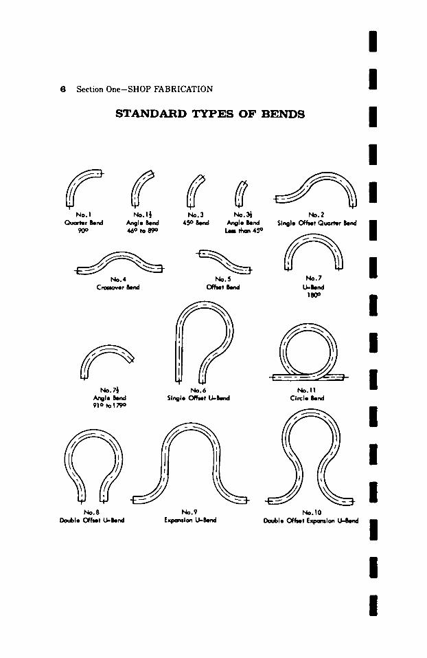
S T A N D A R D T Y P E S O F B E N D S
/ /
No.l No.1�89 No.3 No.~ Qvarter Bend Angle Bend 45 ~ Bend Angle Bend
90 ~ 46 ~ to 89o b i than 45 ~
No.4 No.5 Crm,over Bend Off~t Bend
No.7�89 Angle Bend 91o to179 o
No.6 Single O f ~ t U-Bend
No.8 No.9 Double Offer U-Bend E~mndon U-Bend
/
No.2 Single C~T~t Quarter Bend B
II
~.7 / U--h~l
, m
No.11 Circle Bend
I I I
I'4o.10 Double ~ t Expomion U-Bend
I / / / /
I /
Sect ion O n e - S H O P F A B R I C A T I O N 7
/
I
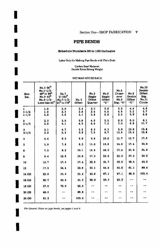
PIPE B E N D S
S c h e d u l e N u m b e r s 2 0 to 1 O0 I n c l u s i v e
Labor Only for Making Pipe Bends with Plain Ends
I / /
Size Ins.
No. l -90 ~ No .1 - I / 2 - 48 ~ to 89 ~ No.7 No.3-45 ~ U- 180 ~ No.3-1/2- No.7-1/2-
Less than 45 ~ 91 ~ to 179 ~
Carbon Steel Material Double Extra Strong Weight
NET MAN HOURS EACH
No. 5 Offset
NO.4 NO.2 NO.6 C r o s s - No.8
Single Single over Double Offset Offset No. 9 Offset
Quar ter "U" Exp. "U . . . . U"
1 1-i/4 1-1/2
2 2-i/2
s-1/2
4
8 / . 10
14 OD
1.6 2.0 2.4 1.8 2.3 2.8 2.0 2.6 3.1
2.3 3.0 3.6 2.9 4.1 4 .5
3.1 4 .7 5.2 3.9 5.2 5.9
4.4 6.3 6.9
5.9 7.8 8.3
7.2 9.2 10.1
9.4 12.6 12.8
12.7 17.4 17.4
17.3 24.4 23.8
22.0 35.4 31.4
No.10 Double Offset
Exp. No . l l
Circ le
3.0 3.6 3.5 4.4 4.9 3.4 4.5 4.6 5.2 5.7 3.8 5.0 5.2 5.9 8.6
4.6 5.5 6.0 6.0 8.1 5.8 7.2 7.5 8.9 11.7
6.3 8.3 8.9 10.0 12.8 7.8 9. 7 10.4 12.4 15.8
8.6 10.8 11.7 13.7 17.3
11.0 13.6 14.6 17.4 22.0
12.8 16.0 17.4 21.9 25.8
17.3 23.5 25.0 27.3 33.0
/
/
16 OD 28.7 M. 4 41 .3
18 OD 37.0 72.0 52.3
20 OD 48.0 - - 66.8
24 OD 81.2 - - 103.4
22.8 31.7 33.8 38.4 43. 9
32.1 44.8 45.6 61. I 69.4
42.8 67. I 67.1 88.8 103.4
I For Ge~wral Notes on pipe bends, see pages 5 and 6.
56.9 83.2 83.2
/

8 Section One-SHOP FABRICATION
P I P E B E N D S
S c h e d u l e N u m b e r s 1 2 0 , 1 4 0 a n d 1 6 0
Labor Only for Making Pipe Bends with Plain Ends
Carbon Steel Material Double Extra Strong Weight
NET MAN HOURS EACH
Size Ins.
1 I-I/4 1-1/2
2 2-1/2
10
12
14 OD
16 OD
18 OD
20 OD
24 OD
No. l -90 ~ N o . I - 1 / 2 - 46 ~ to 89 ~ No.3-45 ~ No.3-1 /2-
Les s than 45 ~
2 .0 2.1 2.4
2.'7 3.4
3.9
5.5
6.0
8.5
11.4
14.8
20.3
26.6
34.4
44.0
54.4
89.2
NO.'/ u-18o o
No.'7-1/2- 91 ~ to 179 ~
2.3 2.6 3.1
3.6 4.'7
5.5
'7.3
9.2
11.0
14.8
20.8
28.3
45.8
64.6
82. '7
No.5 Offset
2.8 3.2 3.8
4 .4 5.'7
6.1
8.5
10.0
11.8
15.2
20. 9
28.8
39. '7
50.9
64.'7
No.4 No.2 No.6 C r o s s - Single Single over Offset Offset No.9
Quar te r "U" Exp."U"
3.6 4 .0 4.'7 4 .2 5.2 5.5 4 .6 6.2 6 .5
5.4 6.9
'7.'7
10.1
12.8
15.5
20.3
26. '7
36.6
50.9
66.4
'7.0 8.6
9.'7
13.4
16.4
19.2
2'7.5
3?.0
53.0
?5.8
103.4
'7.5 9.2
10.4
14.3
1'7.4
20. 1
29.3
39.3
54.9
'75.8
103.4
t'br Ge,eral Notes ( ) , pipe be,ds, see pages 5 a , d 6.
NO.8 Double Offset
ttUtt
5.4 6 .5 '7.3
8.1 10.3
11.?
15.5
20.3
24.8
32.1
45.4
65.8
No.10 Double Offset Exp. No.ll Circle
6.2 "/.2 8.6
9.4 11.'7
14.6
18.9
25. '7
32.1
40. 3
59.5
8'7.8
I I I I I I I I I I I I I I I I
[
I / / /
Section One-SHOP FABRICATION 9
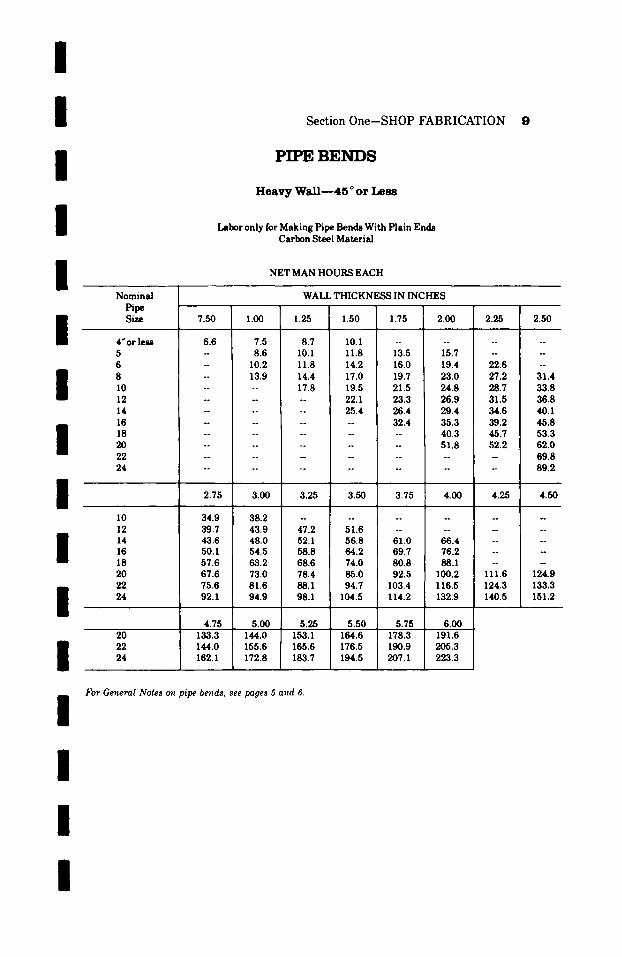
PIPE BENDS
H e a v y W a l l - - 4 5 o or L e s s
Labor only for Making Pipe Bends With Plain Ends Carbon Steel Material
NET MAN H O U R S EACH
I / / / / /
I I I /
Nomina l Pipe Size 7.50 1.00
4" or less 6.6 7.5 5 - 8.6 6 -- 10.2 8 -- 13.9 10 . . . . 12 . . . . 14 . . . . 16 - -- 18 . . . . 2 0 . . . .
22 ! . . . . 24 . . . .
2.75 3.00
10 34.9 38.2 12 39.7 43.9 14 43.6 48.0 16 50.1 54.5 18 ; 57.6 63.2 20 67.6 73.0 22 75.6 81.6 24 92.1 94.9
WALL T H I C K N E ~ IN I N C H E S
1.25 1.50 1.75 2.00 2.25 2.50
8.7 10.1 . . . . . . . 10.1 11.8 13.5 15.7 - - 11.8 14.2 16.0 19.4 22.6 - 14.4 17.0 19.7 23.0 27.2 31.4 17.8 19.5 21.5 24.8 28.7 33.8 -- 22.1 23.3 26.9 31.5 36.8 -- 25.4 26.4 29.4 34.6 40.1 . . . . 32.4 35.3 39.2 45.8 . . . . . . 40.3 45.7 53.3 . . . . . . 51.8 52.2 62.0 . . . . . . . . . 69.8 . . . . . . . . . 89.2
,
3.25 3.50 3.75 4.00 4.25 4.50 _ _ _ _ _ ~
4 7 . 2 5 1 . 6 . . . . . .
52.1 56.8 61.0 66.4 -- 58.8 64.2 69.7 76.2 68.6 74.0 80.8 88.1 -- - 78.4 85.0 92.5 100.2 111.6 124.9 88.1 94.7 103.4 116.5 124.3 133.3 98.1 104.5 114.2 132.9 140.5 151.2
4.75 5.00 20 133.3 144.0 22 144.0 155.6 24 162.1 172.8
5.25 5.50 5.75 ] 6.00 153.1 164.6 178.3 1 191.6 165.6 176.5 190.9 205.3 183.7 194.5 207.1 223.3
For General Notes on pipe bends, see pages 5 and 6.
I
10 Section One-SHOP FABRICATION
PIPE B E N D S
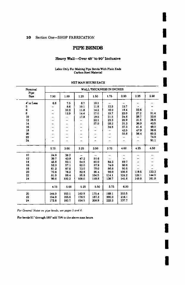
H e a v y W a l l - - O v e r 4 5 ~ t o 9 0 ~ I n c l u s i v e
Labor Only For M a k i n g Pipe Bends Wi th P la in Ends Ca rbon Steel Ma te r i a l
N E T M A N H O U R S E A C H
Nominal WALL THICKNESS IN INCHES Pipe Size 7.50 1.00 1.25 1.50 1.75 2.00
4"or M 6.6 7.5 8.7 10.1 -- - 5 -- 8.6 10.1 11.8 13.5 15.7 6 - 10.2 11.8 14.2 16.0 19.4 8 -- 13.9 14.4 17.0 19.7 23.0 10 . . . . 17.8 19.5 21.5 24.8 12 . . . . . . 22. I 23.3 26.9 14 . . . . . . 27.0 28.2 31.3 16 . . . . . . . . 34.6 37.3 18 . . . . . i .. 42.5 20 . . . . . . . 55.8 22 . . . . . . . . . . . . 24 . . . . . . . . . . .
2.25
. .
22.6 27.2 28.7 31.5 36.0 41.4 47.9 56.4
. .
. ~
2.50
~ 1 7 6
31.4 33.8 36.8 42.5 48.0 56.6 65.2 74.0 91.1
2.75 3.00 3.25 3.50 I 3.75 4.00 4.25 4.50
10 34.9 38.2 . . . . I . . . . . . . . 12 39.7 43.9 47.2 51.6 . . . . . . . . 14 45.8 50.1 54.5 60.0 64.3 69.7 . . . . 16 52.3 57.1 63.0 i 67.9 74.0 80.6 -- - 18 61.2 67.6 73.0 I 79.0 86.8 93.6 . . . . 20 70.8 76.2 82.8 90.4 98.0 106.8 119.5 133.3 22 81.0 88.4 95.8 104.5 114.1 124.2 132.1 144.0 24 96.0 100.2 109.0 119.8 130.7 141.6 149.8 161.0
4.75 5.00 5.25 5.50 5.75 6.00
20 144.0 153.1 163.9 175.4 189.1 203.5 22 154.9 165.6 176.5 187.3 200.3 216.1 24 172.8 183.7 194.5 208.9 223.3 237.7
For General Notes o~l pipe beard.s, see pages 5 and 6.
For bends 91 ~ t h r o u g h 180 ~ add 75% to the above m a n hours.
I I I I I I I I I I I
I
I
I I
I
/ / /
l /
Section One--SHOP FABRICATION 11
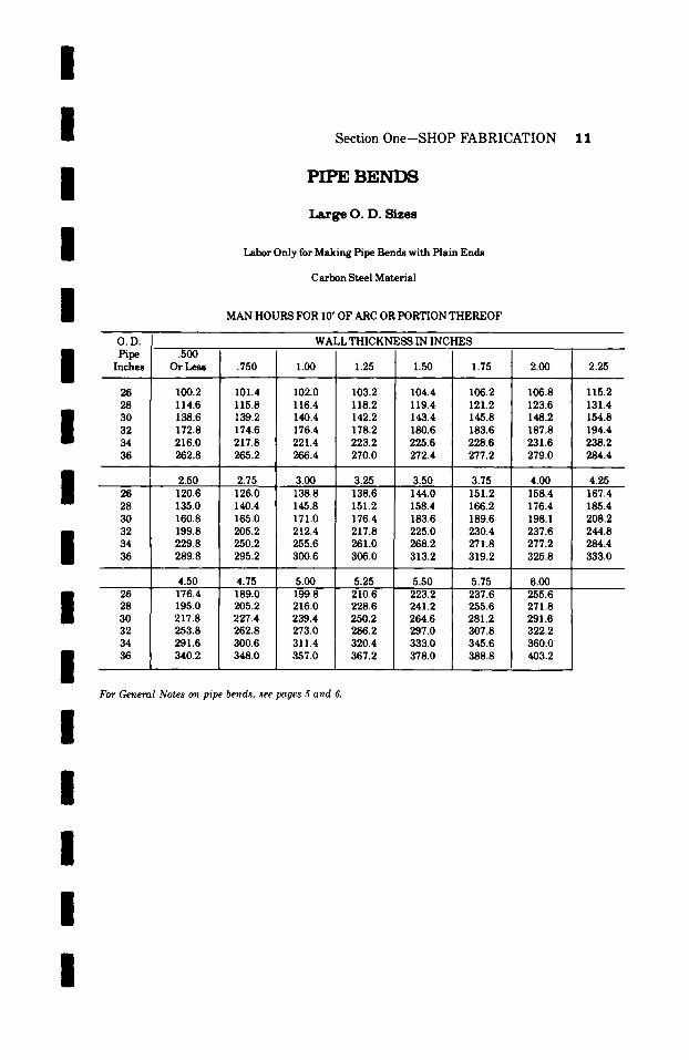
PIPE B E N I ~
Large O. D. Sizes
Labor Only for Making Pipe Bends with Plain Ends
Carbon Steel Material
MAN HOURS FOR I0' OF ARC OR PORTION THEREOF
/ /
I l I I /
I /
I
O.D. Pipe
Inches
26 28 30 32 34 36
26 28
34
26 28 30 32 34 36
.500 Or Less
WALL THICKNESS IN INCHES
�9 750 1.00 1.25 1.50 1.75 2.00
100.2 101.4 102.0 103.2 104.4 106.2 106.8 114.6 115.8 116.4 118.2 119.4 121.2 123.6 138.6 139.2 140.4 142.2 143.4 145.8 148.2 172.8 174.6 176.4 178.2 180.6 183.6 187.8 216.0 217.8 221.4 223.2 225.6 228.6 231.6 262.8 265.2 266.4 270.0 272.4 277.2 279.0
2.50 2.75 3.00 3.25 3.50 3.75 120.6 126.0 138.8 138.6 144.0 151.2 158.4 135.0 140.4 145.8 151.2 158.4 166.2 176.4 160.8 165.0 171.0 176.4 183.6 189.6 198.1 199.8 205.2 212.4 217.8 225.0 230.4 237.6 229.8 250.2 255.6 261.0 268.2 271.8 277.2 289.8 295.2 300.6 306.0 313.2 319.2 325.8
4.50 4.75 5.00 5.25 5.50 5.75 6.00 176.4 189.0 199.8 210.6 223.2 237.6 255.6 195.0 205.2 216.0 228.6 241.2 255.6 271.8 217.8 227.4 239.4 250.2 264.6 281.2 291.6 253.8 262.8 273.0 286.2 297.0 307.8 322.2 291.6 300.6 311.4 320.4 333.0 345.6 360.0 340.2 348.0 357.0 367.2 378.0 388.8 403.2
2.25
115.2 131.4 154.8 194.4 238.2 284.4
4.00 4.25 167.4 185.4 208.2 244.8 284.4 333.0
For General Notes on pipe bends, see pages 5 and 6.
I

1 2 S e c t i o n O n e - S H O P F A B R I C A T I O N
A ~ I ' r A C H I N G F L A N G E S - - - S C R E W E D T Y P E
Labor--Cutting and Threading Pipe--Making on Screwed Flanges and Refacing
Carbon Steel Material For Bends, Headers, Necks and Straight Runs of Pipe
NET MAN HOURS EACH
I I I l I
P i p e
S i z e
I n c h e s
2 o r l e s s . . . .
2-1/2 . . . .
, �9 �9 �9
3-1/2 . . . .
1 2 5 L b . C a s t I r o n
a n d
1 5 0 L b . S t e e l
. . . . . 1 . 0 . . . . . .
I 0
12
14 O D . . . .
1 6 O D . . . .
18 O D . . . .
2 0 O D . . . .
24 O D . . . .
. . . . . 1. I . . . . . .
. . . . . 1 . 2 . . . . . .
. . . . . 1 . 4 . . . . . .
. . . . . 1 � 9 . . . . . .
. . . . . 1 . 6 . . . . . .
. . . . . 1 . 8 . . . . . .
. . . . . 2 � 9 . . . . . .
. . . . . 2 � 9 . . . . . .
. . . . . 3 � 9 . . . . . .
. . . . . 3 . 8 . . . . . .
. . . . . 4 . 6 . . . . . .
. . . . . 5 . 5 . . . . . .
. . . . . 6 . 5 . . . . . .
. . . . . 9 . 3 . . . . . .
250 Lb�9 C a s t I r o n
a n d
S t e e l 3 0 0 L b . a n d H i g h e r
. . . . . . 1 .2
. . . . . . 1 . 3
. . . . . . 1 . 4
. . . . . . 1 . 6
. . . . . . 1 . 7
. . . . . . 1 . 9
. . . . . . 2 . 0
. . . . . . 2 . 4
. . . . . . 2 . 9
. . . . . . 3 . 5
. . . . . . 4 . 3
. . . . . . 5 . 2
. . . . . . 6 . 2
. . . . . . ' / . 4
. . . . . . 1 0 . 6
I I I I l I l
Flanges: M a n h o u r s a r e f o r l a b o r o n l y � 9 T h e p r i c e o f t h e f l a n g e m u s t b e a d d e d in a l l c a s e s � 9
l~pe Thickness : Man h o u r s a r e f o r a n y w a l l t h i c k n e s s o f p i p e u s e d w i t h l i s t e d f l a n g e .
Unlisted Sizes: U n l i s t e d s i z e s t a k e t h e n e x t h i g h e r l i s t i n g .
l l I l
/ /
I / /
S e c t i o n 0 n e - S H O P F A B R I C A T I O N 1 3
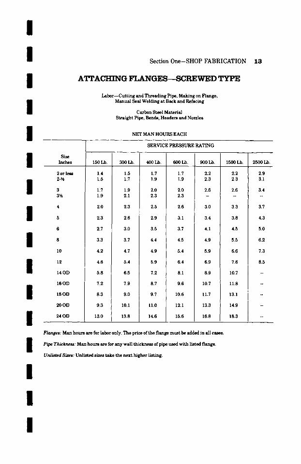
A'I~ACHING F L A N G E S - - S C R E W E D TYPE
Labor--Cutting and Threading Pipe, Making on Flange, Manual Seal Welding at Back and Refacing
Carbon Steel Material Straight Pipe, Bends, Headers and Nozzles
NET MAN HOURS EACH
I I I I I I I
Size Inches
2 or less 2-�89
3 3~
10
12
14OD
16OD
18OD
20OD
24 OD
150 Lb.
1.4 1.5
1.7 1.9
2.0
2.3
2.7
3.3
4.2
4.8
5.8
7.2
8.3
9.3
13.0
SERVICE PRESSURE RATING
300 Lb.
1.5 1.7
1.9 2.1
2.3
2.6
3.0
3.7
4.7
5.4
6.5
7.9
9.0
10.1
13.8
400 Lb.
1.7 1.9
2.0 2.3
2.5
2.9
3.5
4.4
4.9
5.9
7.2
8.7
9.7
11.0
14.6
600 Lb.
1.7 1.9
2.0 2.3
2.6
3.1
3.7
4.5
5.4
6.4
8.1
9.6
10.6
12.1
15.6
900 Lb.
2.2 2.3
2.6
3.0
3.4
4.1
4.9
5.9
6.9
8.9
10.7
11.7
13.3
16.8
1500 Lb.
2.2 2.3
2.6 ~
3.3
3.8
4.5
5.5
6.6
7.6
10.7
11.8
13.1
14.9
18.3
2500 Lb.
2.9 3.1
3.4 . .
3.7
4.3
5.0
6.2
7.3
8.5
/
I I
Flanges: Man hours are for labor only. The price of the flange must be added in all cases.
Pipe Thickness: Man hours are for any wall thickness of pipe used with listed flange.
Unlisted Sizes: Unlisted sizes take the next higher listing.
/

1 4 Sec t ion O n e - S H O P F A B R I C A T I O N
~ A C H r N G F L A N G E S - - S C R E W E D TYPE
Labor--Cutting and Threading Pipe, Making on Flange, Manual Seal Welding at Back and Front and Refacing
Carbon Steel Material, Straight Pipe, Bends, Headers and Nozzles
NET MAN HOURS EACH
Pipe SERVICE P~URE RATING Size
Inches 150 Lb. 300 Lb. 400 Lb. 600 Lb. 900 Lb. 1500 Lb. 2500 Lb.
I I I I
I
2 or less 2�89
3 3�89
10
14OD
16OD
18OD
20OD
24 OD
1.7 1.9
2.1 2.3
2.5
2.9
3.4
4.1
5.3
6.0
7.2
9.0
10.4
11.6
16.2
1.9 2.1
2.3 2.5
2.8
3.2
3.8
4.7
5.8
6.8
8.1
9.9
11.3
12.7
17.3
2.1 2.3
2.5 2.8
3.1
3.6
4.4
5.5
6.2
7.4
8.9
10.9
12.3
13.8
18.2
2.1 2.3
2.5 2.8
3.3
3.9
4.6
5.6
6.8
7.9
9.9
12.1
13.5
15.2
19,6
2.7 2.9
3.2 ~ 1 7 6
3.7
4.2
5.1
6.2
7.5
8.5
11.1
13.6
14.7
16.6
21.0
2.7 2.9
3.2 ~ 1 7 6
4.2
4.8
5.6
6.9
8.3
9.2
12.2
15.0
16.2
18.1
22.5
3.4 3.7
4.0 ~ 1 7 6
4.6
5.3
6.1
7.6
9.3
I0.0
I /
I / / /
/ Flanges: Man hours are for labor only. The price of the flange must be added in all cases.
Pipe Thickness: Man hours are for any wall thickness of pipe used with listed flange.
Unlisted Sizes: Unlisted sizes take the next higher listing. I I I I
/
I I I
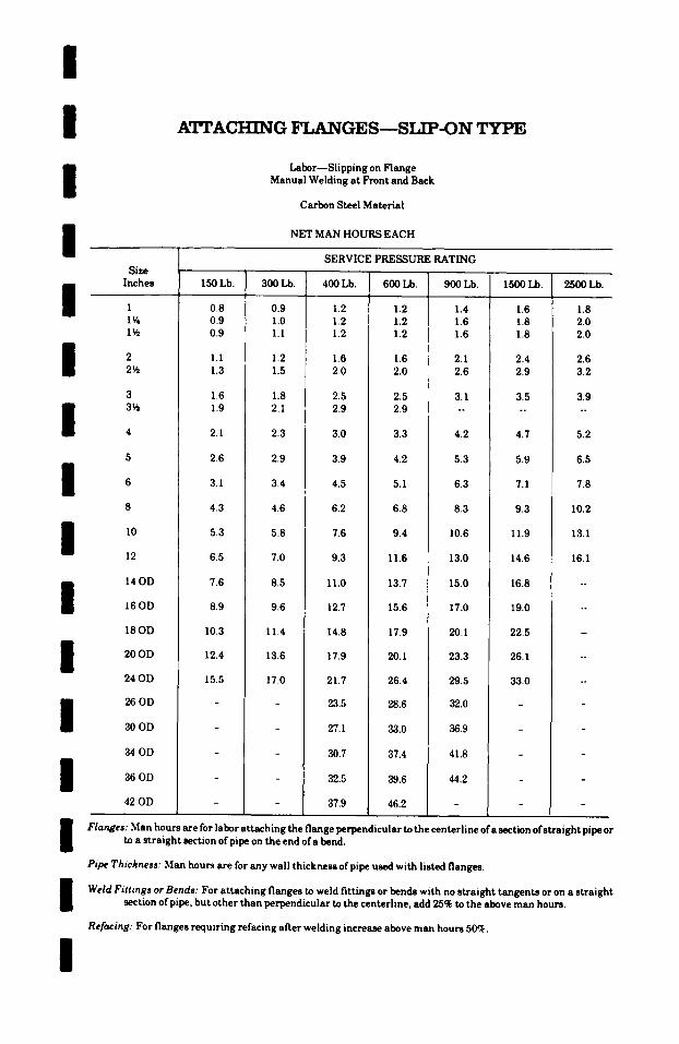
A'ITACHING F L A N G E S - - S I A P - O N TYPE
Labor--Slipping on Flange Manual Welding at Front and Back
Carbon Steel Material
NET MAN HOURS EACH
I I I I I I I I I I I I
SERVICE PRESSURE RATING Size
Inches
1 1�88 1�89
2 2�89
3 3�89
12
14OD
16OD
18OD
20OD
24OD
26 OD
300D
3 4 0 D
3 6 0 D
42 OD
150 Lb.
0.8 0.9 0.9
1.1 1.3
1.6 1.9
2.1
2.6
3.1
4.3
5.3
6.5
7.6
8.9
10.3
12.4
15.5
300 Lb.
0.9 1.0 1.1
1.2 1.5
1.8 2.1
2.3
2.9
3.4
4.6
5.8
7.0
8.5
9.6
11.4
13.6
17.0
400 Lb.
1.2 1.2 1.2
1.6 2.0
2.5 2.9
3.0
3.9
4.5
6.2
7.6
9.3
11.0
12.7
14.8
17.9
21.7
23.5
27.1
30.7
32.5
37.9
600 Lb.
1.2 1.2 1.2
1.6 2.0
2.5 2.9
3.3
4.2
5.1
6.8
9.4
11.6
13.7
15.6
17.9
20.1
26.4
28.6
33.0
37.4
39.6
46.2
900 Lb.
1.4 1.6 1.6
2.1 2.6
3.1 ~ 1 7 6
4.2
5.3
6.3
8.3
10.6
13.0
15.0
17.0
20.1
23.3
29.5
32.0
36.9
41.8
44.2
1500 Lb.
1.6 1.8 1.8
2.4 2.9
3.5 . ~
4.7
5.9
7.1
9.3
11.9
14.6
16.8
19.0
22.5
26.1
33.0
2500 Lb.
1.8 2.0 2.0
2.6 3.2
3.9 ~ 1 7 6
5.2
6.5
7.8
10.2
13.1
16.1
Flanges: Man hours are for labor at taching the flange perpendicular to the centerline of a section of s traight pipe or to a straight section of pipe on the end of a bend.
Pipe Thickness: Man hours are for any wall thickness of pipe used with listed flanges.
Weld Fittings or Bends: For attaching flanges to weld fittings or bends with no straight tangents or on a straight section of pipe, but other than perpendicular to the centerline, add 25% to the above man hours.
Refacing: For flanges requiring refacing after welding increase above man hours 50%.
16 Section One-SHOP FABRICATION
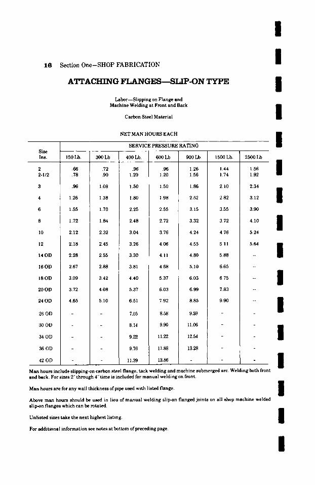
A'I'rACHING FLANGES---SLIP-ON TYPE
Labor--Slipping on Flange and Machine Welding at Front and Back
Carbon Steel Material
NET MAN HOURS EACH
I I I I I [ SERVICE PRESSURE RATING
Size Ins. 150 Lb. 300 Lb. 400 Lb. 600 Lb. 900 Lb. 1500 Lb. 2500 Lb.
2 2-I/2
I0
12
14OD
16OD
18OD
20 OD
24 OD
26 OD
300D
340D
36 OD
42 OD
.66
.78
.96
1.26
1.55
1.72
2.12
2.18
2.28
2.67
3.09
3.72
4.65
.72
.90
1.08
1.38
1.70
1.84
2.32
2.45
2.55
2.88
3.42
4.08
5.10
.96 1.20
1.50
1.80
2.25
2.48
3.04
3.26
3.30
3.81
4.40
5.37
6.51
7.05
8.14
9.22
9.76
11.39
.96 1.20
1.50
1.98
2.55
2.72
3.76
4.06
4.11
4.68
5.37
6.03
7.92
8.58
9.90
11.22
11.88
13.86
1.26 1.56
1.86
2.52
3.15
3.32
4.24
4.55
4.80
5.10
6.03
6.99
8.85
9.59
11.06
12.54
13.28
1.44 1.74
2.10
2.82
3.55
3.72
4.76
5.11
5.88
6.65
6.75
7.83
9.90
1.92
2.34
3.12
3.90
4.10
5.24
5.64
I I I I I I I
Man hours include slipping-on carbon steel flange, tack welding and machine submerged arc. Welding both front and back. For sizes 2" through 4" time is included for manual welding on front.
i
Man hours are for any wall thickness of pipe used with listed flange. / /
Above man hours should be used in lieu of manual welding slip-on flanged joints on all shop machine welded slip-on flanges which can be rotated.
am
Unlisted sizes take the next highest listing, l
For additional information see notes at bottom of preceding page.
I

/ / / /
Section One-SHOP FABRICATION 17
A T T ~ H I N G F L A N G E S - - W E L D N E C K T Y P E
I.abor-Aligning Flange and Butt Welding
Carbon Steel Material NET MAN HOURS EACH
I / / / / / / / /
] SERVICE PRESSURE RATING Size Ins. 1"50 Lb. ~ l,b. 400 l,b. 600 l,b. 900 Lb. 1500 l,b. ] 2500 Lb.
1
2 1.05 1.20 1.20 1.'50 1.50 1.60 1.70
21/,z
12
14 OD
16 OD
18 OD
2 0 0 D
24 OD
26 OD
30 OD
OD
36 OD
42 OD
1.40
1.70
2.10
2 . ~
3.60
4.50
5.25
6.10
7.10
8.30
9.10
10.20
1.60
1.90
2.,30
3.20
3.90
4.80
5.70
6.60
7.70
8.90
9.90
11.10
1.60
1.90
2.30
3.20
3.90
4.80
5.70
6.60
7.70
8.90
9.90
11.10
12.03
13.88
15.73
16.65
19.43
1.80
2.20
2.60
3.50
4.30
5.30
6.30
7.40
8.60
10.10
11.20
12.70
13.76
15.88
18.00
19.06
22.23
1.80
2.20
2.60
3.50
4.30
5.30
6.30
7.40
8.60
10.10
11.20
12.70
13.76
15.88
18.00
19.06
1.90
2.30
2.90
3.90
4.90
6.10
7.40
8.90
11.30
12.00
14.30
16.30
2.20
2.40
3.00
4.00
5.10
6.20
8.00
/ /
Man hours include aligning and tack welding carbon steel weld neck flange and machine submerged arc butt welding to pipe.
Man hours are for any wall thickness of pipe used with listed flanges.
Unlisted sizes take the next highest listing.
/

1 8 Section One-SHOP FABRICATION
A T T A C H I N G O R I F I C E F L A N G E S - - SLIP-ON A N D T H R E A D E D T Y P E S
Carbon Steel Material
MAN HOURS PER PAIR
I SERVICE PRESSURE RATING
Slip-On Type Threaded Types Size Ins. 300 Lb. 300 Lb. 400-600 Lb. 900-1500 Lb.
/ / / / /
10
20
26
3O
36
42
5.3
6.5
9.0
12.2
15.5
18.3
22.0
25.1
28.7
33.9
41.0
53.4
60.5
69.0
74.1
80.1
4.7
6.5
8.0
9.9
12.8
16.1
18.5
21.2
24.5
27.8
35.3
7.4
9.3
12.9
15.8
18.9
8.3
9.5
12.0
14.8
18.2
21.6
/
l l / / / / /
Slip-On Types: Man hours include slipping on, welding, placement of paddle-type plates, and bolting of pair of orifice flanges.
Threaded Types: Man hours include screwing on, placement of paddle-type plates, and bolting up of pair of orifice-
type flanges.
All man hours exclude cutting, beveling, or threading of pipe. See respective tables for these man hours.
/ /
l
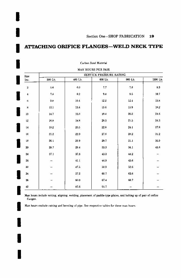
/ / / /
Section One-SHOP FABRICATION 19
A T T A C H I N G O R I F I C E F L A N G E S - - W E L D N E C K T Y P E
Carbon Steel Material
MAN HOURS PER PAIR
Size Ins.
3
/ ' 6
8 10
SERVICE PRESSURE RATING
3(}() I,b. 400 Lb. 600 Lb. 900 Lb.
5.6 6.0 7.7 7.8
7.8 8.2 9.4 9.5
9.8 10.4 12.2 12.4
13.1 13.4 15.6 15.9
14.7 15.0 19.4 20.2
12 16.8 18.8 20.3 21.5
19.2 20.5 22.8 24.1
16 21.2 22.0 27.6 28.2
26.1 26.9 29.7 31.1
28.7 29.4 3,3.3 34.1
37.1 37.8 43.3 44.2
4 I. 1 44.9 45.6
:30 47.5 50.9 52.6
I 57.2 60.7 62.6
60.0 67.4 68.7
42 87.6 91.7
14
18
20
24
l 34
36
1500 Lb.
8.3
10.7
13.8
18.2
21.6
24.3
27.8
31.2
35.9
41.6
/ Man hours include setting, aligning, welding, placement of paddle-type plates, and bolting up of pair of orifice
flanges.
Man hours exclude cutting and beveling of pipe. See respective tables for t h e ~ man hours.
/
l l
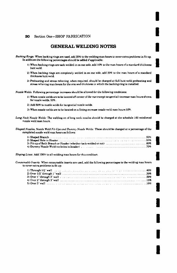
20 Section One-SHOP FABRICATION
GENERAL WET.DING NOTES
I I I
Backing Rings: When backing rings are used, add 25% to the welding man hours to cover extra problems in fit.up. In addition the following percentages should be added if applicable: I
| I) When backing rings are tack welded in on one side, add I0~ to the man hours of a standard thickness butt weld.
2) When backing rings are completely welded in on one side, add 30ch to the man hours of a standard thickness butt weld. B
m 3) Preheating and stress relieving, when required, should be charged at full butt weld preheating and stress relieving man hours for the size and thickness in which the backing ring is installed.
Nozzle Welds: Following percentage increases should be allowed for the following conditions:
1) When nozzle welds are to be located off-center ofthe run(except tangential) increase man hours shown for nozzle welds, 50~.
2) Add 80~ to nozzle welds for tangential nozzle welds.
3) When nozzle welds are to be located on a fitting increase nozzle weld man hours 50~.
Long Neck Nozzle Welds: The welding-on of long neck nozzles should be charged at the schedule 160 reinforced nozzle weld man hours.
Shaped Nozzles, Nozzle Weld Fit-Ups and Dummy Nozzle Welds: These should be charged at a percentage of the completed nozzle weld man hours as follows:
11 Shaped Branch . . . . . . . . . . . . . . . . . . . . . . . . . . . . . . . . . . . . . . . . . . . . . . . . . . . . . . . . . . . . . . . . . . . . . . . . . . 5 ~ 2) Shaped Hole in Header . . . . . . . . . . . . . . . . . . . . . . . . . . . . . . . . . . . . . . . . . . . . . . . . . . . . . . . . . . . . . . . . . . . 50% 3) Fit-up of Both Branch or Header {whether tack-welded or not) . . . . . . . . . . . . . . . . . . . . . . . . . . . . . . . 60~ 4) Dummy Nozzle Weld (no holes in header) . . . . . . . . . . . . . . . . . . . . . . . . . . . . . . . . . . . . . . . . . . . . . . . . . . 70qr
Sloping Lines: Add 100% to all welding man hours for this condition.
Consumable Inserts: When consumable inserts are used, add the following percentages to the welding man hours to cover extra problems in fit-up:
I) Through 1/2" wall ....................................................................... 40c~ 2) Over I/2" through I" wall ................................................................ 30~ 3) Over 1" through 2" wall .................................................................. 20~ 4) Over 2" through 3" wall .................................................................. 15% 5) Over 3" wall ............................................................................ 10%,
I I I I I I I I I I I
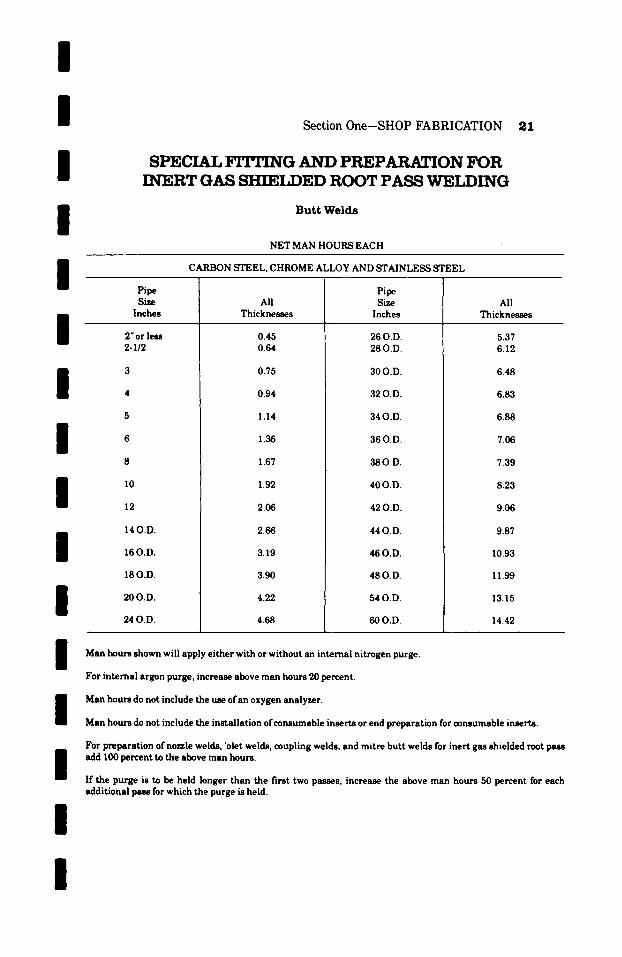
I I I I
Section One-SHOP FABRICATION 21
SPECIAL FITTING AND PREPARATION FOR INERT GAS SI-WET,DED ROOT PASS WET,f l iNG
B u t t W e l d s
NET MAN HOURS EACH
I Pipe
CARBON STEEL, CHROME ALLOY AND STAINLESS STEEL
Pipe
I I I I I I
Size Inches
2" or less 2-I12
10
140.D.
16 O.D.
18 O.D.
200.D.
24 O.D.
All Thicknesses
0.45 0.64
0.75
0.94
1.14
1.36
1.67
1.92
2.06
2.66
3.19
3.90
4.22
4.68
Size Inches
26 O.D. 28 O.D.
300.D.
32 O.D.
34 O.D.
36 O.D.
38 O.D.
40 O.D.
42 O.D.
44 O.D.
480.D.
48 O.D.
54 O.D.
60 O.D.
All Thicknesses
5.37 6.12
6.48
6.83
6.88
7.06
7.39
8.23
9.06
9.87
10.93
11.99
13.15
14.42
I I I I
Man hours shown will apply either with or without an internal nitrogen purge.
For internal argon purge, increase above man hours 20 percent.
Man hours do not include the use of an oxygen analyzer.
Man hours do not include the installation of consumable inserts or end preparation for consumable inserts.
For preparation of nozzle welds, 'olet welds, coupling welds, and mitre butt welds for inert gas shielded root pass add 100 percent to the above man hours.
If the purge is to be held longer than the first two passes, increase the above man hours 50 percent for each additional pass for which the purge is held.
I
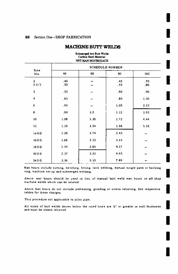
Section One-SHOP FABRICATION
M A C H I N E BTj'.rr ~VET.T'~3 Submerg~ Arc Butt Welds
Carbon Steel Material NET MAN HOURS EACH
S C H E D U L E NUMBER
I I I I
Size Ins.
2 2 -1 /2
I0
12
14OD
160.D
180.D.
20OD
24 O D
40
.40
.50
.55
.65
.90
.99
1.08
1.19
1.26
1.68
2.19
2.37
3.36
60
1.0
1.36
1.54
1.74
2.13
2.85
3.51
5.10
80
.45
.55
.60
.80
1.05
1.12
1.72
1.96
2.43
3.15
4.17
4.95
7.89
160
.70
.80
.90
1.30
2.15
2.92
4.44
5.32
/ / / I / /
Man hours inc lude cu t t ing , beve l ing , f i t t i ng , tack we ld ing , manual s ing le pass or back ing r ing, machine set-up and submerged we ld ing .
Above man hours should be used in l ieu of manual but t we ld man hours on a l l shop machine we lds wh ich can be rotated.
Above man hours do not inc lude preheat ing, g r ind ing or s t ress re l i ev ing . See respec t i ve tab les for these charges.
Th is procedure not applzcable to a l loy pipe.
A l l s izes of butt we lds shown below the ru led l i nes are �88 or greater in wa l l t h i ckness and must be s t ress re l ieved.
/ / / / / I
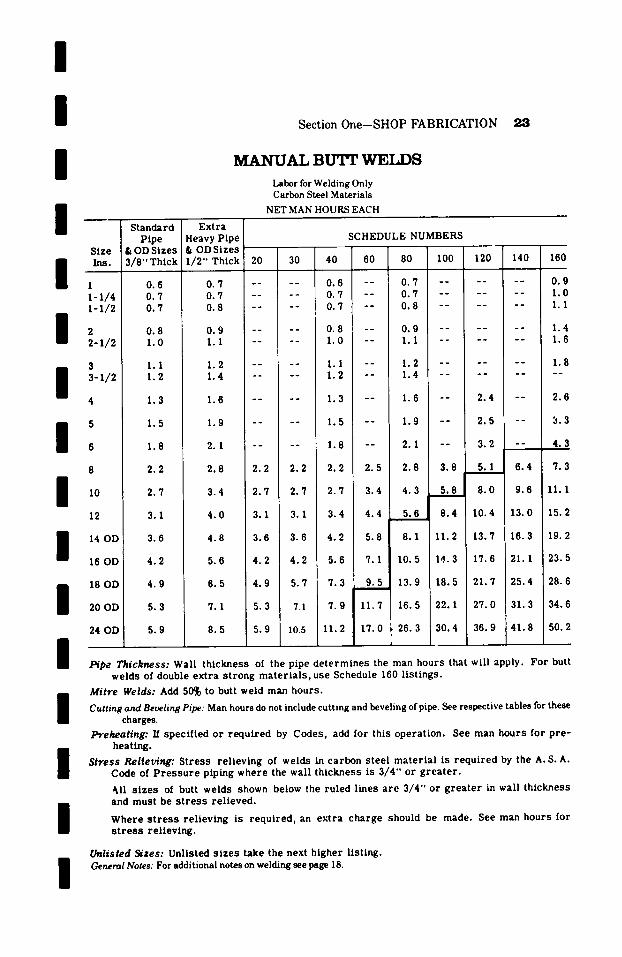
/ /
Section One-SHOP FABRICATION 2,3
I I
Size
I Ins. 1 i-I/4 I-I/2
~.-1/2
3 3-1/2
4
I 5 6
10
12
I 14 OD 16 OD
i 18 OD
20 OD
24 OD
I I /
I /
S t a n d a r d P i p e
& OD S i z e s 3 / 8 " T h i c k
0 . 6 0 . 7 0 . 7
0 . 8 1 . 0
1.1 1.2
1.3
1.5
1.8
2.2
2.7
3.1
3.6
4.2
4.9
5.3
5.9
M A N U A L BU'I 'r WET,DS
Labor for Welding Only Carbon Steel Materials
NET MAN HOURS EACH
E x t r a H e a v y P i p e & OD Sizes ' I/2" Thick 20 30 ' 4C
SCHEDULE NUMBERS
60 80 i I00 120 140 160
0 . 7 . . . . 0 . 6 - - 0 . 7 . . . . . . 0 . 9 0 . 7 . . . . 0 . 7 - - 0 . 7 . . . . . . 1 . 0 0 . 8 . . . . 0 . 7 - - 0 . 8 . . . . . . 1 .1
0.9 . . . .
1.1 ....
1.2 --
1.4 --
1.6 --
1.9 --
2. I --
2.8 2.2 2.2
3 . 4 2 . 7 2 . 7
4 . 0 3.1 3.1
0.8 1.0
1.1 1.2
1.3
1.5
1.8
2.2
2.7
3.4
4.2
5.6
4.8 3.6 3.6
5.6 4.2 4.2
0.9 . . . . . . 1.4 1.1 . . . . . . 1.6
- - 1 . 2 . . . . . . 1 . 8
- - 1 . 4 . . . . . . . .
- - 1.6 - - 2.4 2.6
-- 1.9 -- 2.5 -- 3.3
-- 2.1 -- 3.2 -- 4.3
2 . 5 2 . 8 3 . 8 5 . 1 6 . 4
3 . 4 4 . 3 5 . 8 1 8 . 0 9.6
7 . 3
1 1 . 1
4.4 5 .61 8.4 10.4 13.0 15.2
5 . 8 8 . 1 1 1 . 2 1 3 . 7 1 6 . 3 1 9 . 2
7. I 10.5 la.. 3 17.6 2l. 1 23.5
6.5 4.9 5.7 7.3 9.5 13.9 18.5 21.7 25.4 28.6
7. I 5.3 7.1 7.9 11.7 16.5 22.1 27.0 31.3 34.6
8.5 5.9 10.5 11.2 17.0 . 26.3 30.4 i 36.9 41.8 50.2
Pipe Thickness: Wall thickness of the pipe determines the man hours that will apply. For butt welds of double extra strong materials, use Schedule 160 listings.
Mitre Welds: Add 50% to butt weld man hours.
Cutting and Belling Pipe: Man hours do not include cutting and beveling of pipe. See respective tables for these charges.
Preheating: If specified or required by Codes, add for this operation. See man hours for pre- heating.
Stress Relfet~ng: Stress relieving of welds in carbon steel material is required by the A. S. A. Code of Pressure piping where the wall thickness is 3/4" or greater.
~ll sizes of butt welds shown below the ruled lines are 3/4" or greater in wall thickness and must be stress relieved.
Where stress relieving is required, an extra charge should be made. See man hours for stress relieving.
~isted Sizes: Unlisted sizes take the next higher listing. General Notes: For additional notes on welding see page 18.

2.,4
Nominal
Section One-SHOP FABRICATION
1VL~NUAL H E A V Y W.AT,T, B u T r V~T,T~
Labor for Welding Only
Carbon Steel Material
NET MAN HOURS EACH
WALL T H I C K N ~ IN INCHES
I / / / /
Pipe Size .750 1.00
3 2.3 3.1 4 2.8 3.5 5 -- 4.0 6 -- 5.4 8 -- 7.4 10 . . . . 12 . . . . 14 . . . . 16 -- - 18 . . . . 20 . . . . 22 . . . . 24 . . . .
2.75 3.00
10 31.1 35.7 12 36.3 41.6 14 41.4 47.0 16 47.7 54.8 18 53.3 61.8 20 63.9 71.6 22 69.8 78.6 24 75.8 83.9
4.75 5.00
20 160.8 172.3 22 173.6 186.3 24 189.4 203.9
1 .25
~ 1 7 6
4.8 5.7 7.2 8.6
11.4 o .
~ 1 7 6
~
~ 1 7 6
~ 1 7 6
. ~
3.25
. ~
46.9 53.3 61.8 70.2 82.1 89.4 96.9
5.25
183.8 203.9 222.8
1 .50
. ~
5.8 6.8 8.8
11.1 13.7 16.6 19.9
~ 1 7 6
. .
3.50
~ 1 7 6
53.5 60.4 70.2 80.5 92.6
101.1 109.5
5.50
191.4 214.1 233.5
1.75
~ 1 7 6
~
8.5 11.3 14.0 17.0 19.7 22.5 25.3
. ~
. ~
3.75
~ 1 7 6
o .
68.8 80.8 91.9
105.2 114.9 124.9
5.75
213.1 234.6 252.7
2.00
. ~
. ~
10.5 13.2 16.3 19.7 23.2 26.4 30.2 33.7 39.3
~ 1 7 6
4.00
o .
o .
77.2 91.2
105.2 119.3 130.6 141.9
6.00
227.2 250.1 270.3
For General Notes o , welding, see pages "20 and 23.
2.25
~ 1 7 6
~
~ 1 7 6
15.4 19.2 23.1 27.5 30.9 35.2 39.3 46.4
~ 1 7 6
. .
4.25
~
. ~
~ 1 7 6
~
~
135.3 148.1 160.8
2.50
~ 1 7 6
~
~
~
23.2 27.2 31.8 36.5 42.1 46.4 56.1 61.3 66.7
4.50
. ~
~
~ 1 7 6
~ 1 7 6
~ 1 7 6
146.7 163.9 177.4
I I I I / /
I / / / /

i / i i i / / / i
i
i
i
i
Section One-SHOP FABRICATION
MANUAL LARGE O.D. BU'I~ W E L I ~
Labor for Welding Only
Carbon Steel Material
NET MAN HOURS EACH
O.D. PIPE
INCHES
26 28 30 32 34 36 38 40 42 44 46 48 54 60
26 28 30 32 34 36
26 28 30 32 34 36
WALL THICKNESS IN INCHES
.375 .500 .750 I 1.00 1.25 1.50 I 1.75 2.00
7.1 9.7 12.8 17.1 22.6 29.2 36.8 44.5 8.5 11.1 13.9 18.8 24.8 31.6 39.3 47.2
10.6 12.9 16.0 20.4 26.9 33.7 42.0 49.9 13.1 15.2 18.2 22.6 29.6 36.4 44.7 52.6 16.4 18.2 20.7 25.0 33.3 39.1 47.7 55.4 19.5 20.9 23.6 28.1 38.3 44.1 52.8 60.8 22.9 24.5 27.1 31.4 44.1 49.8 58.1 66.2 26.8 29.0 31.2 35.2 50.6 56.2 63.9 72.2 31.3 34.2 36.0 39.5 58.3 63.6 70.2 78.7 36.3 39.5 42.3 48.3 63.5 70.5 76.5 85.8 40.9 45.0 49.4 57.5 70.1 77.5 83.3 92.9 46.2 50.8 57.7 67.0 77.0 84.7 90.5 100.1 52.0 57.3 67.4 78.1 84.5 92.6 98.3 107.9 58.5 64.6 78.7 91.0 92.8 101.2 106.8 116.3
2.75 2.50 2.75 3.00 3.25 3.50 3.75 4.00
52.3 72.0 81.6 93.2 104.7 117.4 135.3 152.9 55.1 77.1 88.5 99.6 117.1 127.4 148.1 165.4 57.9 84.3 95.7 107.2 122.2 136.5 157.0 177.4 60.5 88.1 100.8 112.6 129.7 144.2 166.9 188.9 65.2 93.2 107.2 120.5 136.8 152.9 177.4 201.6 70.3 99.6 114.3 127.7 145.5 162.9 188.6 211.9
4.25 4.50 4.75 5.00 5.25 5.50 5.75 6.00
172.3 191.4 206.7 221.8 234.6 252.7 274.3 293.0 186.3 207.5 221.5 237.4 253.9 272.9 292.8 311.4 199.1 219.0 238.6 255.2 273.1 291.0 314.5 339.0 211.9 234.8 252.7 270.6 291.0 310.0 334.4 359.9 227.2 252.7 270.6 288.9 310.9 331.8 357.3 382.8 239.4 265.4 285.9 305.8 328.0 349.7 377.7 405.3
For General Notes on welding, see pages '20 alwl 23.
I
i
I
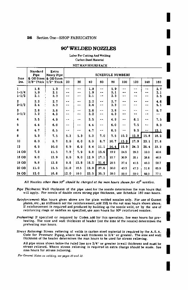
I
Section One-SHOP FABRICATION
90 ~ WEt.bED NOZZLES Labor For Cutting And Welding
Carbon Steel Material
NET MAN HOURS EACH
I I I
Size Ins.
1 1-1/4 ~-1/9.
2 2 - 1 / 2
3 3-1/2
4
5
6
8
10
12
14 OD
16 OD
18 OD
20 OD
24 OD
Standard Pipe
& OD Sizes 3 / 8 " Thick
1.8 1 .9 2.1
2 .2 2 .4
2 .8 3 .2
3 .5
4 .4
4 .7
5.3
6 . 0
6 .9
7 .9
9 .0
9 .8
11.0
12.0
E x t r a H e a v y P i p e & OD Sizes 1/2" Thick 20 30
1.9 . . . . 2.1 . . . . 2.3 . . . .
2.7 . . . . 3.3 . . . .
3.8 . . . . 4.3 . . . .
4.9 . . . .
6.0 . . . .
6.5 . . . .
7.5 5.3 5 .3
8 .7 6 .0 6 .0
10.0 6 .9 6 .9
11.5 7 . 9 ! 7 .9
12.9 9 .0 9 .0
13.8 9 .8 12.8
15.5 11.0 15.5
16.8 12.0 180
40
1.8 1 .9 2.1
2 .2 2 .4
2 .8 3 .2
3 .5
4 .4
4 .7
5.3
6 .0
8 .4
9 .8
12.9
SCHEDULE NUMBERS
60 80 100 120 140 160 n m
m J i
-- 1.9 . . . . . . 2.'/ - - 2.1 . . . . . . 3 .1 - - 2.3 . . . . . . 3.5 n / - - 2 . 7 . . . . . . 4 . 6 - - 3 . 3 . . . . . . 5 . 1
- - 3 .8 . . . . . . 5 .7 - - 4 .3 . . . . . . . .
- - 4 .9 6 .1 - - 7 .5
- - 6 . 0 7 . 5 - - 9 . 3
I - - 6 .5
7 .0 7 .5
8 .7 10.7
- - 9 .5 - - 12.1 /
10.2 12.9 i 15.8 18.2
13.9 i 17.9 23.1 27.8
II. I 14.4 19.9 24.3 29.4 33.2 n
l 13.6 19.2 24.5 29.3 33.0 40.6
17. I 22.7 30.9 35.1 38.8 46.9
16.2 , 21.6 25.5 37.4 41.5 45.0 58.7 n
/ 18.9 27.6 30.0 43.3 473 51.6 65.9
23.5 35.3 39.0 55.0 59.0 660 77. I
n
All Nozz les other than 90 ~ should be charged at the man hours shown f o r 45 ~ nozzles . 1
m Pipe Thickness: Wall th ickness of the pipe used for the nozzle d e t e r m i n e s the man hours that
will apply. For nozzle of double ext ra s t rong pipe th ickness , use Schedule 160 man hours . m
Reinforcement: Man hours given above a r e for plain welded nozzles only. For use of Gusse t 1 p la tes , e t c . , a s s t i f f ene r s not for r e in fo rcemen t , add 25% to the net man hours shown above. 1 If r e i n f o r c e m e n t ts r equ i r ed and produced by building up the nozzle weld, or by the use of r e in fo rc ing r tngs or saddles as speci f ied , use man hours for 900 r e in fo rced nozzles .
1
Preheating: If speci f ied or r equ i r ed by Codes, add for this opera t ion . See man hours for p r e - 1 heating. The s ize and wall th ickness of header (not the s ize of the nozzle) d e t e r m i n e s the /
p rehea t ing man hours .
Stress Relieving: St re s s re l iev ing of welds in carbon s tee l ma te r i a l Is r equ i r ed by the A. S.A. 1 Code for P r e s s u r e Piping, where the wall th ickness is 3 / 4 " or g r e a t e r . The s ize and wall II th ickness of the header d e t e r m i n e s the man hours to be used for s t r e s s re l iev ing .
All pipe s i ze s shown below the ru led line a r e 3 /4" or g r e a t e r In wall th ickness and must be s t r e s s re l i eved . Where s t r e s s re l i ev ing is r equ i r ed an ext ra charge should be made. See 1 man hours for s t r e s s re l ieving. l
For General Notes on welding, see pages .20 and Z3.
I
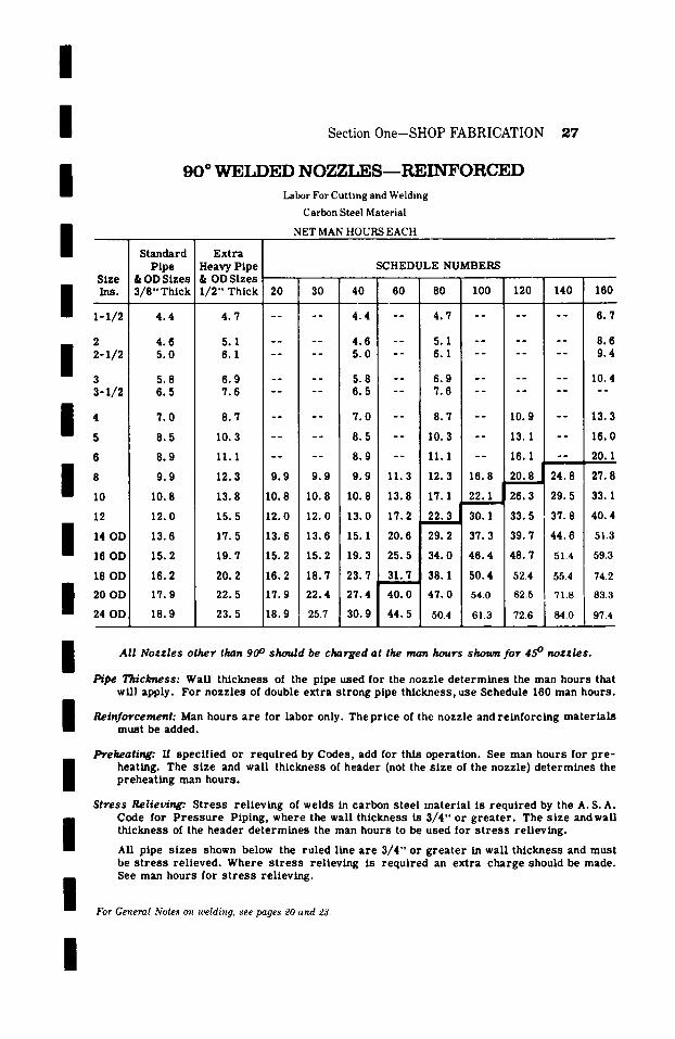
/
I /
/
Section 0ne-SHOP FABRICATION 2 7
9 0 ~ W E L D E D N O g T ~ , E S - - - R E I N F O R C E D
Labor For Cutt ing and Welding
Carbon Steel Material
NET MAN HOURS EACH
S t a n d a r d E x t r a
S ize
1-1/~-
2 z-1/2
s s-1/z
m 4 5
8 I0
12
I 14 OD 16 OD
18 OD 20 OD 24 OD
P i p e & OD S izes 3 / 8 " Th ick
4 . 4
4 . 6 5 . 0
5 .8 6 . 5
7 . 0
8 . 5
8 . 9
9 . 9
10 .8
12 .0
13 .6
15 .2
16 .2
17 .9
18 .9
Heavy P i p e SCHEDULE NUMBERS & OD S izes 1 / 2 " Th i ck 20 30 40 60 80 100 120 140
4 . 7 . . . . 4 . 4 - - 4 . 7 . . . . . .
5 .1 . . . . 4 . 6 - - 5 .1 . . . . . . 6 .1 . . . . 5 . 0 - - 6 .1 . . . . . .
6 . 9 . . . . 5 .8 - - 6 . 9 . . . . . . 7 . 6 . . . . 6 . 5 - - 7 .6 . . . . . .
8 . 7 . . . . 7 . 0 - - 8 . 7 - - 10 .9 - -
10 .3 . . . . 8 . 5 - - 10 .3 - - 13.1 - -
11.1 . . . . 8 . 9 - - 11.1 - - 16.1 - - h
12.3 9 . 9 9 . 9 9 . 9 11 .3 12 .3 16 .8 2 0 . 8 J 24 .8
13 .8 10 .8 10 .8 10 .8 13 .8 17 .1 22 .1 26 .3 29 .5
15 .5 12 .0 12 .0 13 .0 17 .2 22 .3 30 .1 33 .5 37 .8
17 .5 13 .6 13 .6 15.1 20 .6 29 .2 37 .3 39 .7 4 4 . 6
19 .7 15 .2 15 .2 19 .3 25 .5 3 4 . 0 4 6 . 4 4 8 . 7 51.4
2 0 . 2 16 .2 18 .7 2 3 . 7 31 .7 38 .1 50 .4 524 554
22 .5 17 .9 2 2 . 4 27 .4 4 0 . 0 4 7 . 0 54.0 62.5 71.8
2 3 . 5 18 .9 257 30 .9 4 4 . 5 50.4 613 726 840
160
6 . 7
8 .6 9 .4
10 .4 _ _
13.3
16 .0
20. 1
27 .8
33 .1
4 0 . 4
51.3
59.3
74.2
83.3
97.4
I I
Al l N o z z l e s o ther than 90 ~ should be charged at the man hours shown f o r 45 ~ n o z z l e s .
t~pe Th ickness : W a l l t h i c k n e s s of the p ipe used fo r the n o z z l e d e t e r m i n e s the man h o u r s that wil l apply . F o r n o z z l e s of double e x t r a s t r o n g p ipe t h i c k n e s s , u se Schedu le 160 man h o u r s .
Re in fo rcemen t : Man h o u r s a r e for l a b o r only. The p r i c e of the n o z z l e and r e i n f o r c i n g m a t e r i a l s m u s t be added.
Preheating:. If s p e c i f i e d or r e q u i r e d by C o d e s , add for th is o p e r a t i o n . See man h o u r s for p r e - hea t ing . The s i z e and wa l l t h i c k n e s s of h e a d e r (not the s i z e of the nozz l e ) d e t e r m i n e s the p r e h e a t i n g man h o u r s .
S t re s s Relieving:. S t r e s s r e l i e v i n g of we lds in c a r b o n s t e e l m a t e r i a l i s r e q u i r e d by the A. S. A. Code for P r e s s u r e P ip ing , w h e r e the wa l l t h i c k n e s s ts 3 / 4 " o r g r e a t e r . The s i z e and wa l l t h i c k n e s s of the h e a d e r d e t e r m i n e s the man h o u r s to be used for s t r e s s r e l i e v i n g .
All p ipe s i z e s shown below the r u l e d l ine a r e 3 / 4 " o r g r e a t e r in wa l l t h i c k n e s s and m u s t be s t r e s s r e l i e v e d . W h e r e s t r e s s r e l i e v i n g is r e q u i r e d an e x t r a c h a r g e shou ld be made . See man h o u r s for s t r e s s r e l i e v i n g .
I For General Notes on welding, see pages 20 and 23.
I
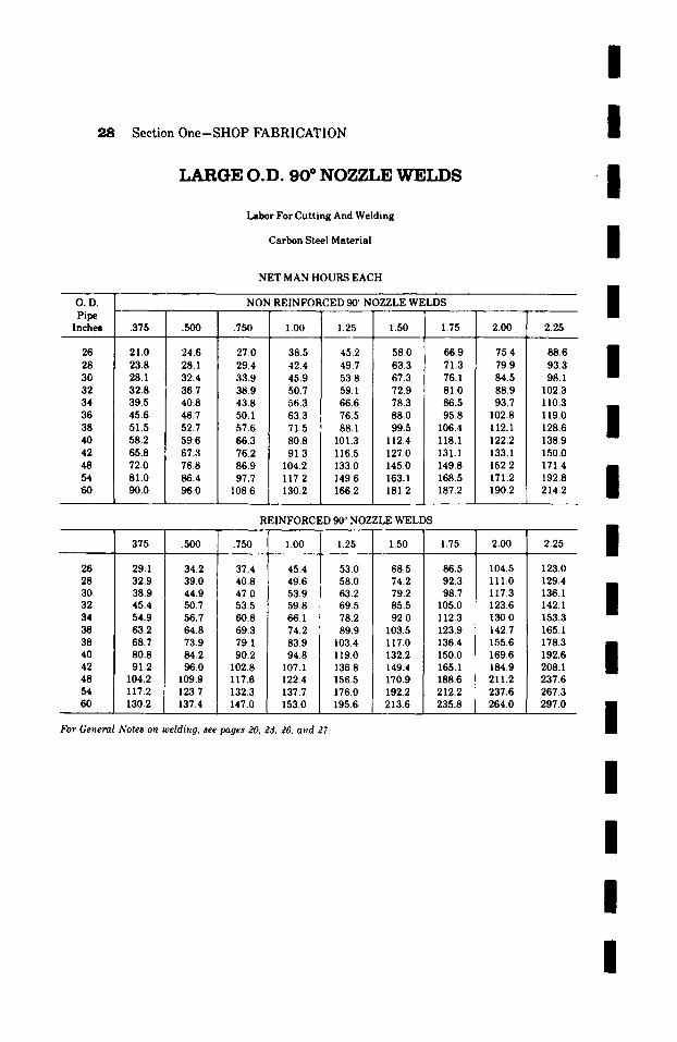
I
Section One-SHOP FABRICATION I L A R G E O . D . 9 0 ~ N O Z Z L E W E L D S
Labor For Cutting And Welding
Carbon Steel Material
NET MAN HOURS EACH
O.D. Pipe Inches
26 28 30 32 34 36 38 40 42 48 54 60
/
I n
NON REINFORCED 90 ~ NOZZLE WELDS m
.375 .500 .750 1.00 1.25 1.50 1.75 2.00 2.25
21.0 24.6 27.0 38.5 45.2 58.0 66.9 75.4 88.6 n
| 23.8 28.1 29.4 42.4 49.7 63.3 71.3 79.9 93.3 28.1 32.4 33.9 45.9 53.8 67.3 76.1 84.5 98.1 32.8 36.7 38.9 50.7 59.1 72.9 81.0 88.9 102.3 39.5 40.8 43.8 56.3 66.6 78.3 86.5 93.7 110.3 45.6 46.7 50.1 63.3 76.5 88.0 95.8 102.8 119.0 51.5 52.7 57.6 71.5 88.1 99.5 106.4 112.1 128.6 m 58.2 59.6 66.3 80.8 101.3 112.4 118.1 122.2 138.9 65.8 67.3 76.2 91.3 116.5 127.0 131.1 133.1 150.0 72.0 76.8 86.9 104.2 133.0 145.0 149.8 152.2 171.4 n 81.0 86.4 97.7 117.2 149.6 163.1 168.5 171.2 192.8 N 90.0 96.0 108.6 130.2 166.2 181.2 187.2 190.2 214.2
For
REINFORCED 90 ~ NOZZLE WELDS
.750
37.4 40.8 47.0 53.5 60.8 69.3 79.1 90.2
102.8 117.6 132.3 147.0
1.00
45.4 49.6 53.9 59.8 66.1 74.2 83.9 94.8
107.1 122.4 137.7 153.0
1.25
53.0 58.0 63.2 69.5 78.2 89.9
103.4 119.0 136.8 156.5 176.0
1.50
68.5 74.2 79.2 85.5 92.0
103.5 117.0 132.2 149.4 170.9 192.2
195.6 [ 213.6
.375 .500 1.75
86.5 92.3 98.7
105.0 112.3 123.9 136.4 150.0 165.1 188.6 212.2 235.8
2.00
104.5 111.0 117.3 123.6 130.0 142.7 155.6 169.6 184.9 211.2 237.6 264.0
2.25
123.0 129.4 136.1 142.1 153.3 165.1 178.3 192.6 208.1 237.6 267.3 297.0
26 29.1 34.2 28 32.9 39.0 30 38.9 44.9 32 45.4 50.7 34 54.9 56.7 36 63.2 64.8 38 68.7 73.9 40 80.8 84.2 42 91.2 96.0 48 104.2 109.9 54 117.2 123.7 60 130.2 137.4
General Notes o~z weldi,g, see pages 20, 23, 26, a~d 27.
I
I
I
I
l
I
I
I
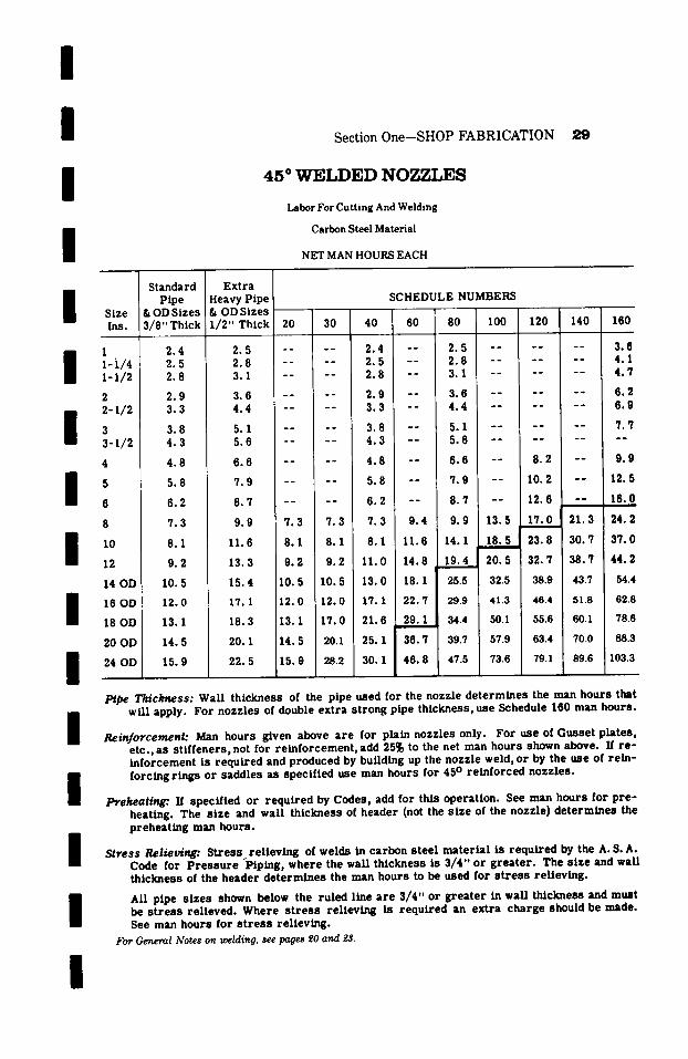
m m Section One-SHOP FABRICATION 29
/
/
4 5 ~ W E L D E D N O Z Z L E S
Labor For Cutting And Welding
Carbon Steel Material
NET MAN HOURS EACH
Size Ins.
/ ' 1-i/4 1-1/2
2 2-1/2
3-1/~.
4
5
S
12
14 OD
m 16 OD
18 OD
20 OD
m 24 OD
/ /
m m
Standard P ipe
& OD Sizes 3 / 8 " Thick
2 .4 2 . 5 2 .8
2 . 9 3 .3
3 .8 4 . 3
4 . 8
5 .8
6 . 2
7 . 3
8 .1
9 . 2
10 .5
12 .0
13.1
14 .5
15 .9
E x t r a Heavy P ipe SCHEDULE NUMBERS & OD Sizes ~ ' �9 ' I / 2 " Thick 20 30 40 60 80 100 120 140 160
2 .5 . . . . 2 .4 - - 2 . 5 . . . . . . 3 .6 2 . 8 . . . . 2 .5 - - 2 . 8 . . . . . . 4 .1 3 .1 . . . . 2 .8 - - 3 .1 . . . . . . 4 . 7
3 .6 . . . . 2 .9 - - 3 .6 - " I . . . . 6 . 2 4 . 4 . . . . 3 .3 - - 4 . 4 . . . . . . 6 . 9
5 . 1 = - - - - 3 . 8 - - 5 . 1 . . . . . . 7 . 7
5 .6 . . . . 4 . 3 - - 5 .6 . . . . . . . .
6 . 6 - - 4 . 8 6 . 6 - - 8 . 2 - - 9 . 9
7 . 9 - - 5 .8 7 . 9 - - 10 .2 - - 12 .5
8.7 . . . . 6 . 2 - - 8.7 - - 12 .6 - - 16.0 9 .9 7 .3 7 .3 7 .3 9 .4 9 .9 13 .5 17 .0 .L 21 .3 24 .2
11 .6 8 .1 8 .1 8 .1 11 .6 1 4 . 1 . , 18 .5 ~ 23 .8 , 3 0 . 7 3 7 . 0
13 .3 9 .2 9 .2 11 .0 14 .8 19 .4 L 2 0 . 5 32 .7 38 .7 4 4 . 2
15 .4 tO. 5 10 .5 13 .0 18.1 25.5 32.5 38.9 43.7 54.4
17 .1 12 .0 12 .0 17.1 22 .7 29.9 41.3 46.4 i 51.8 62.8
18 .3 13.1 17 .0 21 .6 29 .1 34.4 50.1 55.6 60.1 78.6
20. I 14 .5 20.1 25. I 36 .7 39.7 57.9 63.4 70.0 88.3 I
2 2 . 5 15 .9 28.2 30. I 4 6 . 8 47.5 73.6 79.1 89.6 103.3
PlDe Thickness: WaU t h i c k n e s s of the p ipe used for the nozz le d e t e r m i n e s the man h o u r s that wil l apply. F o r n o z z l e s of double e x t r a s t r o n g pipe t h i c k n e s s , use Schedule 100 man h o u r s .
Reinforcement: Man h o u r s given above a r e for p la in nozz l e s only. F o r use of G u s s e t p l a t e s , e tc . , as s t l f f e n e r s , not for r e I n f o r c e m e n t , add 25~ to the net man h o u r s shown above. If r e - I n f o r c e m e n t is r e q u i r e d and p r o d u c e d by bui ldIng up the nozz le weld, o r by the use of r e i n - fo rc ing r i n g s o r s a d d l e s as spec i f i ed use man h o u r s for 45 ~ r e I n f o r c e d n o z z l e s .
Preheating:. If spec i f i ed or r e q u i r e d by Codes , add for th is ope ra t i on . See man h o u r s for p r e - hea t ing . The s i z e and wal l t h i c k n e s s of h e a d e r (not the s i z e of the nozz le ) d e t e r m I n e s the p r e h e a t i n g man h o u r s .
Stress Relieving: S t r e s s r e l i e v l n g of we lds In c a r b o n s t e e l m a t e r i a l Is r e q u i r e d by the A. S. A. Code for P r e s s u r e P ip ing , w h e r e the wal l t h i c k n e s s Is 3 / 4 " o r g r e a t e r . The s i z e and wal l t h i c k n e s s of the h e a d e r d e t e r m i n e s the man h o u r s to be used for s t r e s s r e l i e v i n g .
ALl p ipe s i z e s shown below the ru l ed lIne a r e 3 / 4 " o r g r e a t e r In wal l t h i cknes s and m u s t be s t r e s s r e l i e v e d . W h e r e s t r e s s r e l i e v i n g Is r e q u i r e d an e x t r a c h a r g e should be made. See man h o u r s for s t r e s s r e l i e v i n g .
For General Notes on welding, see pages ~0 and 9~S.
I
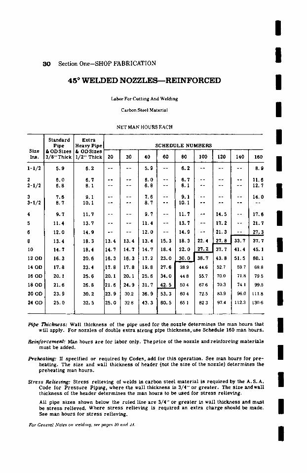
3 0 Section One-SHOP FABRICATION
4 5 ~ W E I ~ E D N O Z Z L E S - - - R E I N F O R C E D
Labor For Cutting And Welding
Carbon Steel Material
NET MAN HOURS EACH
Size Ins.
I-i/2
2 2 - I / 2
3 3 - 1 / 2
4
5
6
8
10
12 OD
14 OD
16 OD
18 OD
20 OD
24 OD
S tanda rd P lpe
& O D S i z e s 3 / 8 " Th ick
5 .9
6 . 0 6 .8
7 .6 8 .7
9 .7
11.4
12 .0
13.4
14.7
16.3
17.8
20.1
21 .6
23 .9
25 .0
E x t r a Heavy P ipe SCHEDULE NUMBERS & OD Sizes 1 / 2 " Th ick 20 30 40 60 80 I00 120 140 160
6 .2 . . . . 5 .9 - - 6 . 2 . . . . . . 8 . 9
6 . 7 . . . . 6 . 0 - - 6 . 7 . . . . . . 11.6 8 .1 . . . . 6 .8 - - 8 .1 . . . . . . 12 .7
9 .1 . . . . 7 .6 - - 9 .1 . . . . . . 14 .0 10.1 . . . . 8 . 7 - - 10.1 . . . . . . . .
11 .7 . . . . 9 . 7 i - - 11 .7 - - 14 .5 - - 17.6 i
13.7 . . . . 11 .4 - - 13 .7 - - 17.2 - - 21 .7
14.9 . . . . 12 .0 - - 14 .9 - - 21 .3 - - 27 .3 I
18 .3 13 .4 13 .4 13 .4 15 .3 18 .3 22 .4 2 7 . 8 3 3 . 7 3 7 . 7
18.4 14.7 I 14 .7 14 .7 18 .4 2 2 . 0 2 7 . 2 ! 3 7 . 7 4 1 . 4 45 .1 I
20.6 16.3 16.3 17.2 23 .0 30 .0 38 .7 43 .8 51 .5 60. 1
23 .4 17.8 17.8 19.8 27 .6 389 446 52.7 597 688
25 .6 20. 1 20.1 25 .6 34 .0 44.8 55.7 70.0 71.8 79.5
26 .8 21 .6 24 .9 31 .7 42 .5 50.4 67.6 70.3 74.1 99.5
30 .2 23 .9 302 36 .9 53 .3 604 725 83.9 960 111.8
32 .5 25 .0 328 43 .3 60 .5 651 823 97.4 112.3 130.6
Pipe Thickness: Wall t h i c k n e s s of the pipe used for the nozz le d e t e r m i n e s the man h o u r s that wil l apply. F o r nozz l e s of double e x t r a s t r o n g pipe t h i c k n e s s , use Schedule 160 man hou r s .
Rein forcement : Man hours a r e for l abor only. The p r i c e of the nozz le and r e i n f o r c i n g m a t e r i a l s m u s t be added.
Preheating: If spec i f i ed or r e q u i r e d by Codes , add for th i s ope ra t i on . See man h o u r s for p r e - hea t ing . The s i ze and wal l t h i c k n e s s of h e a d e r (not the s i ze of the nozz le ) d e t e r m i n e s the p r e h e a t i n g man hou r s .
S t ress Relieving: S t r e s s r e l i e v i n g of welds in c a r b o n s t e e l m a t e r i a l is r e q u i r e d by the A. S. A. Code for P r e s s u r e P ip ing , whe re the wall t h i c k n e s s is 3 / 4 " or g r e a t e r . The s i z e and wal l t h i c k n e s s of the h e a d e r d e t e r m i n e s the man h o u r s to be used for s t r e s s r e l i e v i n g .
All pipe s i z e s shown below the r u l e d l ine a r e 3 / 4 " or g r e a t e r in wal l t h i c k n e s s and m u s t be s t r e s s r e l i e v e d . W h e r e s t r e s s r e l i e v i n g is r e q u i r e d an ex t r a c h a r g e should be made . See man h o u r s for s t r e s s r e l i ev i n g .
For General Notes on welding, see pages 20 and 23.
i i I i i I I I I I I I
i
I
i
i
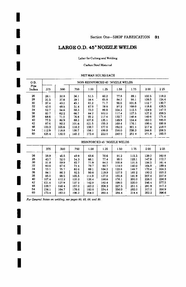
/ /
Section One-SHOP FABRICATION 31
/
77.5 87.6
L A R G E O . D . 4 5 ~ N O Z Z L E W E L D S
Labor for Cutting and Welding
Carbon Steel Material
NET MAN HOURS EACH
I O.D. NON-REINFORCED 45 ~' NOZZLE WELDS Pipe [ Inches .375 .500 .750 1.00 [ 1.25 1.50 1.75 2.00
I 26 28.1 32.8 36.1 51.5 60.2 77.8 89.1 28 31.5 37.6 39 1 56.4 I 65.8 84.2 95.1 30 37.4 43.2 45.1 61.2 [ 71.7 90.0 101.6 32 43.6 48.8 51.4 67.9 ] 78.8 97.2 108.0 34 52.7 54.6 58.3 75.0 88.8 104.3 115.5 36 60.7 62.2 66.7 84.2 102.0 117.4 127.5
40 42
/
48 100.3
I 54 112.9 60 125.4
.375 .500 .750 1.00 1.25
For
26 28 30 32 34 36 38 40 42 48 54 60
71.0 80.9 92.2
105.6 118.8 132.0
76.8 95.2 I 117.4 132.7 140.4 88.3 107.6 ] 135.1 149.9 154.4
101.6 121.5 ] 155.3 169.4 176.1 116.2 138.7 ] 177.6 192.0 201.1 130.7 156.1 199.8 216.0 226.3 145.2 173.4 222.0 240.0 251.4
I I
REINFORCED 45 ~ NOZZLE WELDS
/
1.50
38.9 45.5 43.7 52.0 51 8 59.9 60.6 67.6 73.1 75.7 84.1 86.3 95.0 98.5
107.4 112.2 121.4 127.9 138.7 146.4 156.1 164.7 173.4 183.0
49.9 63.6 70.6 54.3 66.1 77.4 62.7 71.9 84.2 71.4 79.7 92.7 81.0 88.1 104.3 92.5 99.0 119.9
105.5 111.9 137.9 120.3 126.4 158.6 137.2 142.9 182.4 157.0 163.2 208.3 176.6 183.6 234.4 196.2 204.0 260.4
1
General Notes on welding, see pages 20, 2& 29, and 30.
1.75 2.00
91.2 99.0
105.8 114.0 122.6 137.9 155.8 176.1 199.0 227.5 256.0 284.4
100.5 106.5 112.7 118.8 124.9 137.2 149.6 163.0 190.4 217.4 244.6 271.8
/
115.3 123.1 131.5 140.0 149.7 165.2 181.9 200.0 220.0 251.5 283.0 314.4
139.3 147.9 156.3 164.8 173.4 190.2 207.4 226.0 246.4 281.8 317.0 352.2
2.25
I18.2 124.4 130.7 136.5 147.3 158.5 171.4 185.0 199.8 228.0 256.5 285.0
2.25
163.8 172.7 181.4 189.4 204.3 220.2 237.9 256.9 277.5 317.3 356.9 396.6
/ / /
I
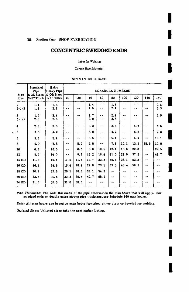
32 Section One-SHOP FABRICATION
CONCENTRIC SWEDGED ENDS
Labor for Welding
Carbon Steel Material
NET MAN HOURS EACH
Standard Extra
/ I / I /
Pipe & O D S izes 3 / 8 " T h i c k
1.4 1.6
1.7 2 .0
2 .3
3 .0
3 .6
5 .0
6 .6
8 .7
11.5
16.4
20. 1
23.3
31 .0
SCHEDULE NUMBERS Heavy Pipe & OD Sizes 1 /2" Thick 20 30 40 60 80 I00 120 140
1.8 . . . . 1 .4 - - 1.8 . . . . . . 2 .1 . . . . 1 .6 - - 2.1 . . . . . .
2 .4 . . . . 1 . 7 - - 2.4 . . . . . . 2.8 . . . . 2 . 0 - - 2 . 8 . . . . . .
3 . 3 . . . . 2 . 3 - - 3 . 3 - - 4 . 7 - -
4 . 2 . . . . 3 . 0 - - 4 . 2 - - 6 . 6 - -
5 . 4 . . . . 3 . 6 - - 5 . 4 - - 8 . 9 - -
7 . 8 - - 5 . 0 5 . 0 - - 7 . 8 10 .1 13 .2 1 5 . 5
1 0 . 5 - - 6 . 6 6 . 6 1 0 . 5 12 .4 1 5 . 8 2 2 . 6 - -
1 4 . 0 - - 8 . 7 13 .2 1 6 . 4 2 1 . 0 2 7 . 9 3 7 . 2 - -
19 .4 11.5 11.5 18.7 23.3 30. 3 38.1 52.8 - -
2 4 . 8 16 .4 1 6 . 4 2 4 . 8 2 9 . 5 3 3 . 5 4 3 . 4 58.3 - -
3 2 . 6 20. 1 3 0 . 3 3 8 . 1 5 4 . 3 . . . . . . . .
36.5 23.3 36.5 42 .7 65.1 . . . . . . . .
50. 5 31 .0 50. 5 . . . . . . . . . . . .
160 /
2 . 8 3 . 3
3., /
5.6
,8 l 10.1
17.0
2 9 . 5 /
42 .7
PiPe Thickness: The wall th ickness of the pipe d e t e r m i n e s the man hours that wiU apply. For swedged ends on double ex t ra s t rong pipe th ickness , use Schedule 160 man hours .
E~ds: All man hours a r e based on ends being furn ished e i ther plain or beveled for welding.
Unlisted Sizes: Unlisted s i z e s take the next h igher l l s ~ .
I
I
I I
I

I I I I I Standard
Section One-SHOP FABRICATION
E C C E N T R I C S W E D G E D E N D S
Labor for Welding
Carbon Steel Material
NET MAN HOURS EACH
E x t r a
S ize I n s .
2 2 - 1 / 2
m 3 3 - 1 / 2
I 5 6
I I0 12
/ /
14 OD
16 OD
18 OD
20 OD
24 OD
Pipe & OD Sizes 3/8"Thick
1 .6 1 . 7
2 . 0 2 . 3
2 . 7
3 . 5
4 . 3
6 . 2
8 . 1
1 1 . 6
1 6 . 4
2 3 . 2
2 7 . 5
3 0 . 5
4 3 . 5
H e a v y P i p e S C H E D U L E N U M B E R S & OD tiizes" - r " 1/2" Thick 20 30 40 60 80 100 120 140 160
| o ! ! t - t
1 . 9 . . . . 1 . 6 " - 1 . 9 . . . . . . 3 . 4
2 , 5 . . . . 1 . 7 - - I 2 . 5 . . . . . . 4 . 0
2 . 8 . . . . 2 . 0 - - 2 . 8 . . . . . . 4 . 5
3 . 3 . . . . 2 . 3 - - 3 . 3 . . . . . . . .
3 . 9 . . . . 2 . 7 - - 3 . 9 - - 6 . 2 6 . 6
5 . 2 . . . . 3 . 5 - - 5 . 2 - - 6 . 2 i - - 9 . 0 I
6 . 2 . . . . 4 . 3 - - 6 . 2 - - 11 .1 - - 1 2 . 5
10 .1 6 . 2 6 . 2 6 . 2 - - 10 .1 12 .4 1 7 . 0 1 8 . 7 2 0 . 4
1 3 . 7 8. I 8 . 1 8 . 1 1 3 . 7 1 7 . 0 2 1 . 0 2 7 . 2 - - 3 8 . 8 I
1 7 . 9 1 1 . 6 1 1 . 6 1 7 . 9 2 1 . 7 2 7 . 9 3 7 . 2 4 8 . 1 - - 5 4 . 2
2 5 . 6 16 .4 1 6 . 4 2 6 . 3 3 1 . 8 3 8 . 8 4 9 . 7 6 8 . 2 - -
34 .1 2 3 . 2 2 3 . 2 3 4 . 1 4 0 . 3 4 4 . 3 5 8 . 3 7 6 . 0
4 6 . 5 2 7 . 5 2 7 . 5 5 1 . 2 7 2 . 2 - - i . . . . i
5 3 . 3 3 0 . 5 30. 5 5 8 . 3 8 5 . 3 . . . .
6 9 . 8 4 3 . 5 4 3 . 5 . . . . . . . .
/ t~pe Thickness: T h e w a l l t h i c k n e s s of the p i p e d e t e r m i n e s the m a n h o u r s tha t w i l l a p p l y . F o r
s w e d g e d e n d s on d o u b l e e x t r a s t r o n g p i p e t h i c k n e s s , u se S c h e d u l e 160 m a n h o u r s .
Ends: All m a n h o u r s a r e b a s e d on e n d s b e i n g f u r n i s h e d e i t h e r p l a i n o r b e v e l e d fo r w e l d i n g .
Unlisted 3izes: U n l i s t e d s i z e s t a k e the n e x t h i g h e r l i s t i n g .
/
I /
/
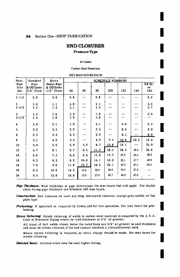
/
3 4 S e c t i o n O n e - S H O P F A B R I C A T I O N
END C I ~ S U R E S P r e s s u r e T y p e
All Labor
Carbon Steel Materials
NET MAN HOURS EACH
Som. Pipe Size Ins.
1-1//2
2 2 - 1 / 2
3 3-I/2
4
5
6
8
10
12
14
16
18
20
24
Standard Pipe
& ODSizes 3/8" Thick
0.8
1.0 1.1
1.3 1.4
1.6
2 .0
2 .3
3.1
3 .9
4 .7
5 .6
6 .3
7 .6
8 .2
9 .0
E x t r a Heavy Pipe & OD Sizes I/2" Thick
0 .9
1.1 1.3
1.6 1.8
2.1
2.5
2.9
4.0
5.0
6.1
7.3
8.2
9.6
10.6
12.6
40
0 .8
1 .0 1.1
1 .3 1.4
1 .6
2 . 0
2 .3
3 .1
3 .9
5 .7
6 .8
8 .2
1 1 . 8
14.2
16.6
SCHEDU]~E NUMBERS XX Hy.
o r 60 80 100 120 140 160
-- 0 .8 . . . . . . 2.0
- - 1.1 . . . . . . 3 .0 - - 1 .3 . . . . . . 3. V
i - - 1 .6 . . . . . . 3 .9 - - 1 .8 . . . . . . . .
- - 2.1 - - 4 . 9 - - 5.2
-- 2.5 -- 6.5 -- 6.9
-- 2.9 -- 8.1 -- 8.9
-- 4.0 7.5 10.6 12.5 13.2
5.0 8.7 10.8 18. I -- 20.9
6.5 1 I. 0 16.0 24.2 19.5 28.6
8 .4 12.8 17.7 27.9 26.4 39.2
10.6 14.1 19.9 32.1 37.7 49.8
13.7 18.5 25.1 36.3 47.5 60.4
16.8 22.9 30.3 40.5 57.3 - -
I 19.9 i 27.3 35.7 44.2 67.0 - -
I I I I I I I I I I
P~pe Thickness: Wall t h i c k n e s s of pipe d e t e r m i n e s the man h o u r s that wil l apply. Fo r double EE e x t r a s t r o n g pipe t h i c k n e s s use Schedule 160 man hou r s . /
ConstrucNo~. End c l o s u r e s as such a r e shop f a b r i c a t e d c l o s u r e s ; o r a n g e p e e l , s a d d l e , o r flat p la te type.
Preheating:. If spec i f i ed or r e q u i r e d by Codes , add for th is ope ra t i on . See man hour s for p r e - / hea t ing . m
Stress Rel~uin~F. S t r e s s r e l i e v i n g of welds in c a r b o n s t ee l m a t e r i a l is r e q u i r e d by the A. S. A. Code of Pressure Piping where the wall thickness is 3/4" or greater. I
| All sizes of butt welds shown below the ruled lines are 3/4 .~ or greater in wall thickness nnd must be stress relieved, if the end closure involves a circumferential weld.
Where stress relieving is required, an extra charge should be made. See man hours for stress relieving. I
~ted Sizes: Unlisted sizes take the next higher listing.
I
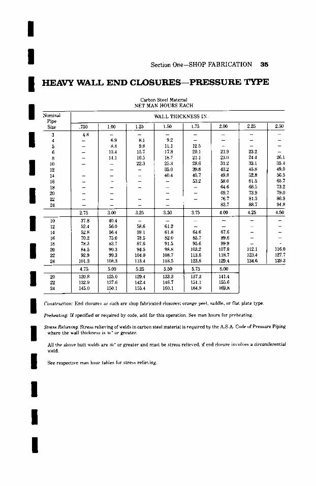
/ / / /
Section One-SHOP FABRICATION 35
H E A V Y W A L L E N D C L O S U R E S - - P R E S S U R E T Y P E
Carbon Steel Material NET MAN HOURS EACH
Nominal WAI, L THICKNESS IN.
I / / I /
Pipe Size
10 12 14 16 18 20 22 24
.750 1.00 1.25
6.9 8.4
13.4 14.1
8.1 9.8
15.7 16.5 22.3
1.50 1.75
4.6 9.2
11.1 17.8 18.7 25.3 35.0 40.4
12.5 20.1 21.1 28.6 39.6 45.7 53.2
2.00
21.9 23.0 31.2 43.2 49.8 58.0 64.6 69.7 76.7 83.7
2.25
23.2 24.4 33.1 45.8 52.8 61.5 68.5 73.9 81.3 88.7
l 20 22 24
2.75
37.8 52.4 52.8 70.2 78.3 84.5 92.9
101.3
4.75 120.8 132.9 145.0
2.50
40.4 56.0 56.4 75.0 83.7 ,90.3 99.3
108.3
26.: ,35. 49.( 56.~ 65. 73.1 79.q 86.! 94.1
3.00 3.25 3.50 3.75 4.00 4.25 4.5(3 u
58.6 59.1 78.5 87.6 94.5
104.0 113.4
5.25
129.4 142.4 155.4
61.2 61.8 82.0 91.5 98.8
108.7 118.5
5.50
133.3 146.7 160.1
m
64.6 85.7 95.6
103.2 113.6 123.8
5.75
137.3 151.1 164.9
67.6 89.6 99.9
107.8 118.7 129.4
6.00
141.4 155.6 169.8
112.1 123.4 134.6
5.00
125.0 137.6 150.1
l16.q 127. 139.:
/ Construction: End closures as such are shop fabricated closures; orange peel, ~ddle, or flat plate type.
Preheating." If specified or required by code, add for this operation. ~r man hours for preheating.
I Stress Relieving: Stress relieving of welds in carbon steel material is required by the A.S.A. Code of Pressure Piping where the wall thickness is :~4" or greater.
All the above butt welds are :r or greater and must be stress relieved, if end closure involves a circumferential weld.
See respective man hour tables for stress relieving.
/
l /
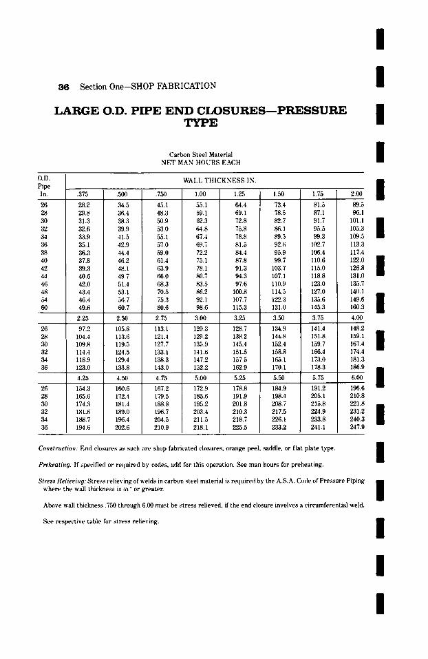
36 Section One-SHOP FABRICATION
L A R G E O.D. P I P E E N D C I X ) S U R E S - - P R E S S U R E T Y P E
Carbon Steel Material NET MAN HOURS EACH
l / / /
O.D. Pipe In.
26 28 30 32 34 36
40 42 44 46 48 54 60
26 28 30 32 34 36
26 28 ,30 ,q2 34 36
WALL THICKNESS IN.
.375
28.2 29.8 31.3 32.6 33.9 35.1 36.3 37.8 39.3 40.6 42.0 43.4 46.4 49.6
.500
,34.5 36.4 38.3 39.9 41.5 42.9 44.4 46.2 48.1 49.7 51.4 53.1 56.7 60.7
.750
45.1 48.3 50.9 53.0 55.1 57.0 59.0 61.4 63.9 66.0 68.3 70.5 75.3 80.6
1.00
55.1 59.1 62.3 64.8 67.4 69.7 72.2 75.1 78.1 80.7 83.5 86.2 92.1 98.6
1.25
64.4 69.1 72.8 75.8 78.8 81.5 84.4 87.8 91.3 94.3 97.6
100.8 107.7 115.3
1.50
73.4 78.5 82.7 86.1 89.5 92.6 95.9 99.7
103.7 107.1 110.9 114.5 122.3 131.0
2.25 2.50 2.75 3 .~ 3.25 3.50
113.1 121.4 127.7 133.1 138.3 143.0
97.2 104.4 109.8 114.4 118.9 123.0
128.7 1,38.2 145.4 151.5 157.5 162.9
105.8 113.6 119.5 124.5 129.4 133.8
120.3 129.2 135.9 141.6 147.2 152.2
134.9 144.8 152.4 158.8 165.1 170.1
4.25 4.50 4.75 5 .~ 5.25 5.50
167.2 179.5 188.8 196.7 204.5 210.9
178.8 191.9 201.8 210.3 218.7 225.5
172.9 185.6 195.2 203.4 211.5 218.1
160.6 172.4 181.4 189.0 196.4 202.6
154.3 165.6 174.3 181.6 188.7 194.6
184.9 198.4 208.7 217.5 226.1 233.2
1.75 81.5 87.1 91.7 95.5 99.3
102.7 106.4 110.6 115.0 118.8 123.0 127.0 135.6 145.3
3.75
141.4 151.8 159.7 166.4 173.0 178.3
5.75
191.2 205.1 215.8 224.9 233.8 241.1
89.5 96.1
101.1 / 105.3 109.5 113.3 117.4 122.0 / 126.8 131.0 135.7 140.1 149.6 / 160.3
4.00
148.2
159.1 l 167.4 174.4 181.3 186.9
6.00 /
198.6 210.8 221.8
231.2 l 240.3 247.9
Construction: End closures as such are shop fabricated closures; orange peel, ~ddle, or flat plate type.
Preheating: If specified or required by codes, add for this operation. See man hours for preheating.
Stlvss Reliering: Stress relieving of welds in carbon steel material is re(luired by the A.S.A. Code of Pressure Piping where the wall thickness is :v4" or greater.
Above wall thickness .750 through 6.00 must be stress relieved, if the end closure involves a circumferential weld.
See respective table for stress relieving.
/
/ / /
l
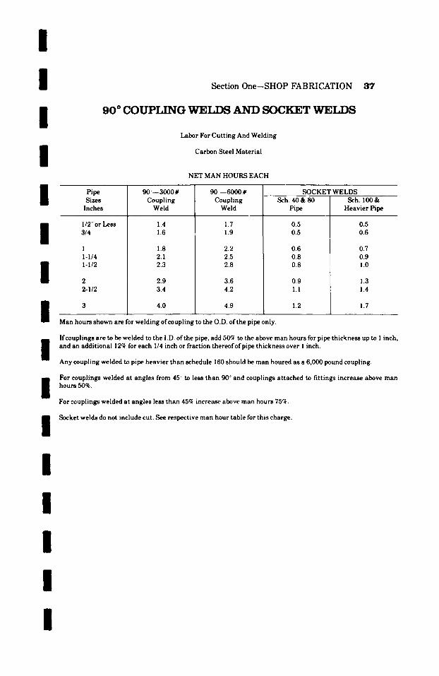
/ /
I /
I /
I
I
Section One-SHOP FABRICATION 37
9 0 ~ C O U P L I N G W E L I ~ A N D S O C K E T W E T . D S
Labor For Cutting And Welding
Carbon Steel Material
NET MAN HOURS EACH
Pipe Sizes Inches
I12'" or Less 314
1 I-I/4 I-I/2
2 2-I/2
90~--3000# Coupling
Weld
1.4 1.6
1.8 2.1 2.3
2.9 3.4
4.0
90--6000# Coupling
Weld
1.7 1.9
2.2 2.5 2.8
3.6 4.2
SOCKET WELDS Sch. 40& 80
Pipe
0.5 0.5
0.6 0.8 0.8
0.9 1.1
4.9 1.2
Sch. 100& Heavier Pipe
0.5 0.6
0.7 0.9 1.0
1.3 1.4
1.7
Man hours shown are for welding ofcoapling to the O.D. of the pipe only.
/
I / /
I
I I
If couplings are to be welded to the I.D. ofthe pipe, add 50~ to the above man hours for pipe thickness up to 1 inch, and an additional 12~ for each 1/4 inch or fraction thereof of pipe thickness over 1 inch.
Any coupling welded to pipe heavier than schedule 160 should be man houred as a 6,000 pound coupling.
For couplings welded at angles from 45 ~ to less than 90 ~ and couplings attached to fittings increase above man hours 50~.
For couplings welded at angles less than 45ck increase above man hours 75~.
Socket welds do not include cut. See respective man hour table for this charge.
/
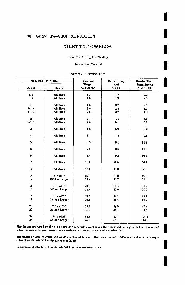
Section 0ne-SHOP FABRICATION
'OT,ET TYPE ~TET,T"~S
Labor For Cutting And Welding
Carbon Steel Material
NET MAN HOURS EACH
NOMINAL PIPE SIZE
Outlet
I/2 3/4
I I-I/4 I-I/2
2 2-I/2
16 16
18 18
20 20
24 24
Header
All Sizes All Sizes
All Sizes All Sizes All Sizes
All Sizes All Sizes
All Sizes
All Sizes
All Sizes
All Sizes
All Sizes
All Sizes
All Sizes
14" and 16" 18" And Larger
16" and 18"' 20" and Larger
18" and 20" 24" and Larger
20" and 24" 26" and Larger
24" and 26" 28" and Larger
Standard Weight
And 2000#
1.3 1.6
1.8 2.0 2.5
3.4 4.0
4.6
6.1
6.9
7.6
8.4
Extra Strong And
3000#
1.7 1.9
2.2 2.5 3.2
4.2 5.1
5.9
7.4
8.1
8.6
9.2
11.8
16.5
20.7 18.4
24.7 21.8
29.3 25.8
35.6 31.0
54.5 45.9
16.9
19.6
23.0 20.7
26.4 23.8
32.1 28.4
39.0 34.7
63.7 55.1
Greater Than Extra Strong And 6000#
2.2 2.6
2.9 3.3 4.3
5.6 6.7
9.2
9.8
11.9
13.9
16.4
26.3
38.9
46.9 51.0
61.2 66.3
79.1 85.2
87.8 94.6
105.3 113.5
I I I I I I I I I I I I I
Man hours are based on the outlet size and schedule except when the run schedule is greater than the outlet schedule, in which case the man hours are based on the outlet size and run schedule.
For elbolet or latrolet welds, and weldolets, threadolets, etc., that are attached to fittings or welded at any angle other than 90 ~ add 50~ to the above man hours.
For sweepolet attachment welds, add 150% to the above man hours.
I I I
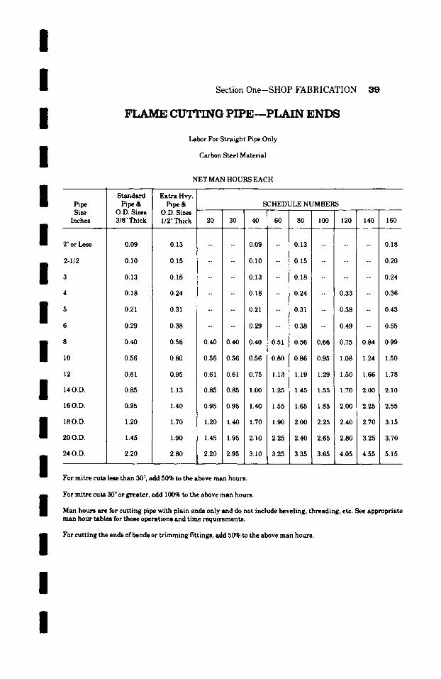
I I Section 0ne-SHOP FABRICATION
/ /
I / /
FLAME ~ G P I P E - - P ~ E N D S
Labor For Straight Pipe Only
Carbon Steel Material
NET MAN HOURS EACH
Pipe Size
Inches
2"or Less
2-I/2
I 5 6
I I I
10
12
14 O.D.
160.D.
18 O.D.
20 O.D.
24 O.D.
Standard Pipe&
O.D. Sizes 3/8" Thick
0.09
0.I0
0.13
0.18
0.21
0.29
0.40
0.56
0.61
0.85
0.95
1.20
1.45
2.20
Extra Hvy. Pipe&
O.D. Sizes 1/2" Thick
SCHEDULE NUMBERS
20 30 40 60 80 I00 120 140 160
0.13 0.09 i 0.13 . . . . . . 0.18
0.15 .... 0.10 -- 0.15 . . . . . . 0.20
0.18 . . . . 0.13 -- 0.18 . . . . . . 0.24
0.24 . . . . 0.18 -- 0.24 -- 0.33 -- 0.36
0.31 . . . . 0.21 -- 0.31 -- 0.38 -- 0.43
0.38 . . . . 0.29 -- 0.38 -- 0.49 -- 0.55
0.56 0.40 0.40 0.40 0.51 0.56 0.66 0.75 0.84 0.99
0.80 0.56 0.56 0.56 0.80 0.86 0.95 1.08 1.24 1.50
0.95 0.61 0.61 0.75 1.13 1.19 1.29 1.50 1.66 1.78
1.13 0.85 0.85 1.00 1.25 1.45 1.55 1.70 2.00 2.10
1.40 0.95 0.95 1.40 1.55 1.65 1.85 2.00 2.25 2.55
1.70 1.20 1.40 1.70 1.90 2.00 2.25 2.40 2.70 3.15
1.90 1.45 1.95 2. I0 2.25 2.40 2.65 2.80 3.25 3.70
/ 2.80 2.20 2.95 3.10 3.25 3.35 3.65 4.05 4.55 5.15
For mitre cuts less than 30 ~ , add 50% to the above man hours.
i For mitre cuts 30 ~ or greater, add 100% to the above man hours.
Man hours are for cutting pipe with plain ends only and do not include beveling, threading, etc. See appropriate man hour tables for these operations and time requirements.
/ For c u t t i n g the ends of bends or t r i m m i n g f i t t ings , add 50% to the above m a n hours .
I I
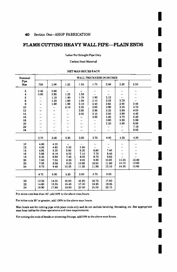
40 Section One-SHOP FABRICATION
FLAME cIPrPING HEAVY W.at.t. PIPE~PL~TN ENDS
Labor For Straight Pipe Only
Carbon Steel Material
NET MAN HOURS EACH
Nominal WALL THICKNESS IN INCHES
I I I I I Pipe ~ '
Size .750 1.00 1.25 1.50 1.75 2.00 2.25 2.50
3 0.45 0.80 . . . . . . . . . . . . 4 0.80 0.95 1.35 1.50 . . . . . . . . 5 -- I . I0 1.40 1.70 1.90 2.15 . . . . 6 -- 1.35 1.60 1.90 2.15 2.35 2.70 -- 8 -- 1.60 1.90 2.10 2.45 2.65 2.95 3.45
10 . . . . 2.10 2.35 2.65 2.90 3.25 3.70 12 . . . . . . 2.65 2.85 3.25 3.60 4.05 14 . . . . . . 3.05 3.15 3.50 3.90 4.45 16 . . . . . . . . 3.65 4.20 4.75 5.20 18 . . . . . . . . . . 3.90 5.20 5.80 20 . . . . . . . . . . 5.20 5.80 6.55 22 . . . . . . . . . . . . . . 7.10 24 . . . . . . . . . . . . . . 8.05
2.75 3.00 3.25 3.50 3.75 4.00 4.25 4.50
I0 4.00 4.25 . . . . . . . . . . . . 12 4.50 4.85 5.20 5.60 . . . . . . . . 14 4.95 5.35 5.60 6.35 6.80 7.45 . . . . 16 5.65 6.10 6.55 7.10 7.70 8.45 . . . . 18 6.35 6.80 7.45 8.05 8.70 9.65 . . . . 20 7.00 7.55 8.30 9.05 9.80 10.65 11.55 12.40 22 7.85 8.50 9.05 10.05 10.95 11.80 12.70 13.65 24 8.70 9.45 10.25 11.20 11.80 13.10 14.30 15.65
4.75 5.00 5.25 5.50 5.75 6.00
I / / I I I
20 13.25 14.05 15.00 15.80 16.75 17.60 22 14.60 15.55 16.40 17.30 18.25 19.25 24 16.90 17.80 18.90 20.00 21.00 22.15 $
For mi t re cuts less than 30 ~ add 50~ to the above man hours.
For mitre cuts 30 ~ or greater, add 100% to the above man hours. R
II Man hours are for cutting pipe with plain ends only and do not include beveling, threading, etc. See appropriate man hour tables for these operations and time requirements.
For cutting the ends of bends or trimming fittings, add 50% to the above man hours. I I I

/ I I / I I / I I I I / / / /
Section One-SHOP FABRICATION 41
FLAME CUTTING LARGE O. D. PIPE---PLAIN E N D S
Labor For Straight Pipe Only
Carbon Steel Material
NET MAN HOURS EACH
O.D. Pipe
Inches
26 28 30 32 34 36 38 40 42 44 46 48 54 60
26 28 30 32 34 36
26 28 30 32 34 36
WALL THICKNESS IN INCHES
�9 375 .500 .750 1.00 1.25 1.50 1.75 2.00
3.50 4.65 5.25 5.65 5.80 6.10 6.35 6.55 4.05 5.05 5.65 6.10 6.30 6.60 6.70 6.95 4.30 5.45 6.10 6.35 6.70 6.95 7.15 7.45 4.75 5.80 6.40 6.80 7.10 7.45 7.70 7.85 5.20 6.40 6.90 7.30 7.55 I 7.85 8.15 8.35 5.80 6.95 7.45 7.85 8.15 8.45 8.70 9.00 6.55 7.15 8.05 8.45 8.70 9.10 9.60 9.90 7.30 8.15 8.80 9.05 9.45 9.85 10.25 10.65 8.15 9.30 9.65 9.90 10.25 10.80 11.20 11.55 9.25 10.20 10.65 10.95 11.40 11.75 12.15 12.55
10.35 11.20 11.70 11.95 12.35 12.85 13.30 13.65 11.70 12.30 12.70 13.10 13.50 13.90 14.45 14.80 13.16 13.83 14.28 14.74 15.18 15.63 16.25 16.65 14.62 15.37 15.87 16.37 16.87 17.37 I 18.06 18.50
2.25 2.50 2.75 3.00 3.25 3.50 3.75 4.00
6.90 8.90 9.65 10.40 11.20 12.15 12.70 14.05 7.45 9.45 9.85 10.65 11.50 12.55 13.15 14.40 7.85 9.90 10.20 10.95 12.00 12.95 13.50 14.85 8.30 10.40 10.80 11.40 12.40 13.35 13.90 15.25 8.80 10.95 11.35 11.75 12.90 13.75 14.30 15.65 9.30 11.40 11.80 12.15 13.30 14.30 14.85 16.20
4.25 i 4.50 4.75 5.00 5.25 5.50 5.75 6.00
15.25 ! 16.55 17.75 18.90 20.10 21.35 22.55 23.75 15.65 17.00 18.15 19.45 20.50 21.75 22.95 24.15 16.05 17.30 18.65 19.85 21.00 22.15 25.35 24.55 16.55 17.80 19.05 20.25 21.40 22.60 23.75 25.00 17.00 18.30 19.50 20.65 21.85 23.10 24.30 25.50 17.40 18.75 20.00 21.20 22.40 23.50 24.75 26.05
For mitre cuts less than 30 ~ , add 50% to the above man hours.
For mitre cuts 30 ~ or greater, add 100~ to the above man hours.
Man hours are for cutting pipe with plain ends only and do not include beveling, threading, etc. See appropriate man hour tables for these operations and time requirements.
For cutting the ends of bends or t r imming fittings, add 50% to the above man hours.
/
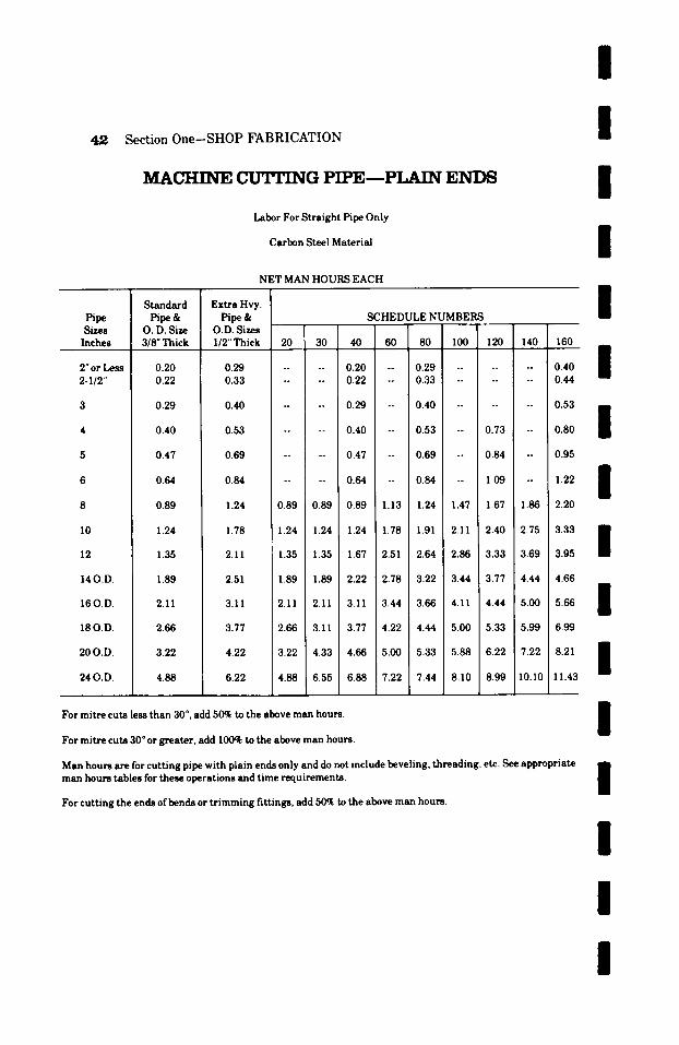
/
4,2 Section One-SHOP FABRICATION I M A C H I N E C U ' I T I N G P I P E - - P L A I N E N D S
Labor For Straight Pipe Only
Carbon Steel Material
I I
NET MAN HOURS EACH
Pipe Sizes
Inches
2" or Less 2-1/2"
Standard Pipe &
O. D. Size 3/8". Thick
0.20 0.22
0.29
0.40
0.47
0.64
0.89
Extra Hvy. Pipe&
O.D. Sizes I12" Thick
0.29 0.33
0.40
0.53
0.69
0.84
SCHEDULE NUMBERS
20 30 40 60 80 100 120 140 160
0.20 0.29 -- 0.40 0.22 0.33 -- 0.44
0.29 0.40
0.40 0.53 -- 0.73
0.47 -- 0.69 -- 0.84
0.~ -- 0.~ -- I.~
1.24 0.89 0.89 0.89 1 . 1 3 1 . 2 4 1 . 4 7 1 . 6 7 1.86
I0
14 O.D.
16 O.D.
18 O.D.
20 O.D.
24 O.D.
1.24
1.35
1.89
2.11
2.66
3.22
4.88
1.78
2.11
2.51
3.11
3.77
4.22
6.22
I I
0.53
0.80 /
0.95
1.22 i 2.20
1.24 1.24 1.24 1.78 1.91 2.11 2.40 2.75 3.33 B
| 1.35 1.35 1.67 2.51 2.64 2.86 3.33 3.69 3.95
1.89 1 . 8 9 2.22 2.78 3.22 3.44 3.77 4.44 4.66
2.11 2 . 1 1 3 . 1 1 3.44 3.66 4 . 1 1 4.44 5.00 5.66 i
2.66 3 . 1 1 3.77 4.22 4.44 5.00 5.33 5.99 6.99
3.22 4.33 4.66 5.00 5.33 5.88 6.22 7.22 8.21 D
/ 4.88 6.55 6.88 7.22 7.44 8.10 8.99 10.10 11.43
i For mitre cuts less than 30 ~ add 50~ to the above man hours, i
i For mitre cuts 30 ~ or greater, add I00~ to the above man hours.
Man hours are for cutting pipe with plain ends only and do not include beveling, threading, etc. See appropriate man hours tables for these operations and time requirements. | For cutting the ends of bends or trimming fittings, add 50ok to the above man hours.
I I I
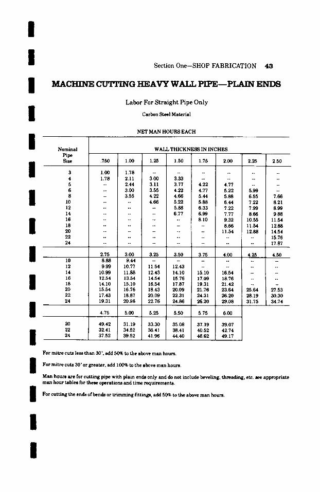
i / /
i /
i / / / / / / / /
n
Section One-SHOP FABRICATION 43
MACHINE CUTTING HEAVY W~IJ, PIPE---PLAIN E N D S
Labor For Straight Pipe Only
Carbon Steel Material
NET MAN HOURS EACH
Nominal Pipe Size
3 4 5 6 8
10 12 14 16 18 20 22 24
10 12 14 16 18 20 22 24
20 22 24
WALL THICKNESS IN INCHES
.750 1.00 1.25 1.50 1.75 2.00 2.25 2.50
1 .00 1 . 7 8 . . . . . . . . . . . .
1.78 2.11 3.00 3.33 . . . . . . . . -- 2.44 3.11 3.77 4.22 4.77 . . . . -- 3.00 3.55 4.22 4.77 5.22 5.99 -- - 3.55 4.22 4.66 5.44 5.88 6.55 7.66 . . . . 4.66 5.22 5.88 6.44 7.22 8.21 . . . . . . 5.88 6.33 7.22 7.99 8.99 . . . . . . 6.77 6.99 7.77 8.66 9.88 . . . . . . . . 8.10 9.32 10.55 11.54 . . . . . . . . . . 8.66 11.54 12.88
. . . . . . . . . 11.54 12.88 14.54
. . . . . . . . . . . . . 15.76
. . . . . . . . . . . . . . 17.87
2.75 3.00 3.25 3.50 3.75 4.00 4.25 4.50 8 . 8 8 9 . 4 4 . . . . . . . . . . .
9.99 10.77 11.54 12.43 . . . . . . . . 10.99 11.88 12.43 14.10 15.10 16.54 . . . . 12.54 13.54 14.54 15.76 17.09 18.76 -- ! -- 14.10 15.10 16.54 17.87 19.31 21.42 . . . . 15.54 16.76 18.43 20.09 21.76 23.64 25.64 27.53 17.43 18.87 20.09 22.31 24.31 26.20 28.19 30.30 19.31 20.98 22.76 24.86 26.20 29.08 31.75 34.74
4.75 5.00 5.25 5.50 5.75 6.00
49.42 31.19 33.30 35.08 37.19 39.07 32.41 34.52 36.41 38.41 40.52 42.74 37.52 39.52 41.96 44.40 46.62 49.17
For mitre cuts less than 30 ~ add 50~ to the above man hours.
For mitre cuts 30~ greater, add 100% to the above man hours.
Man hours are for cutt ing pipe with plain ends only and do not include beveling, threading, etc. see appropriate man hour tables for these operations and time requirements.
For cutt ing the ends ofbends or t r imming fittings, add 50% to the above man hours.
I
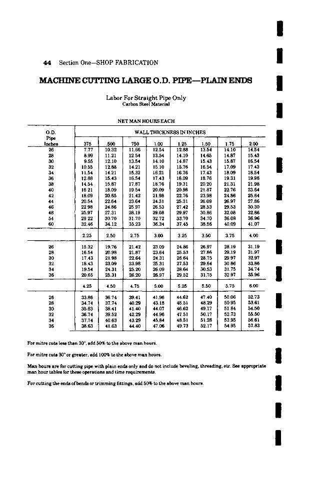
44 Section One-SHOP FABRICATION
MACHINE cuTrING LARGE O.D. PIPE--PLAIN ENDS
Labor For Straight Pipe Only Carbon Steel Material
NET MAN HOURS EACH
I /
I /
O.V. Pipe
Inches .375 .500 .750 1.00 1.25 1.50 1.75 2.00 26 7.77 10.32 11.66 12.54 12.88 13.54 14.10 14.54 28 8.99 11.21 12.54 13.54 14.10 14.65 14.87 15.43 30 9.55 12.10 13.54 14.10 14.87 15.43 15.87 16.54 32 10.55 12.88 14.21 15.10 15.76 16.54 17.09 17.43 34 11.54 14.21 15.32 16.21 16.76 17.43 18.09 18.54 36 12.88 15.43 16.54 17.43 18.09 18.76 19.31 19.98 38 14.54 15.87 17.87 18.76 19.31 20.20 21.31 21.98 40 16.21 18.09 19.54 20.09 20.98 21.87 22.76 23.64 42 18.09 20.65 21.42 21.98 22.76 23.98 24.86 25.64 44 20.54 22.64 23.64 24.31 25.31 26.09 26.97 27.86 46 22.98 24.86 25.97 26.53 27.42 28.53 29.53 30.30 48 25.97 27.31 28.19 29.08 29.97 30.86 32.08 32.86 54 29.22 30.70 31.70 32.72 33.70 34.70 36.08 36.96 60 32.46 34.12 35.23 36.34 37.45 38.56 40.09 41.07
WALL THICKNESS IN INCHES
2.25 2.50 2.75 3.00 3.25 3.50 3.75 4.00
26 15.32 19.76 21.42 23.09 24.86 26.97 28.19 31.19 28 16.54 20.98 21.87 23.64 25.53 27.86 29.19 31.97 30 17.43 21.98 22.64 24.31 26.64 28.75 29.97 32.97 32 18.43 23.09 23.98 25.31 27.53 29.64 30.86 33.86 34 19.54 24.31 25.20 26.09 28.64 30.53 31.75 34.74 36 20.65 25.31 26.20 26.97 29.52 31.75 32.97 35.96
4.25 4.50 4.75 5.00 5.25 5.50 5.75 6.00
26 33.86 36.74 39.41 41.96 44.62 47.40 50.06 52.73 28 34.74 37.74 40.29 43.18 45.51 48.29 50.95 53.61 30 35.63 38.41 41.40 44.07 46.62 49.17 51.84 54.50 32 36.74 39.52 42.29 44.96 47.51 50.17 52.73 55.50 34 37.74 40.63 43.29 45.84 48.51 51.28 53.95 56.61 36 38.63 41.63 44.40 47.06 49.73 52.17 54.95 57.83
For mitre cuts less than 30 ~ , add 50% to the above man hours.
For mitre cuts 30 ~ or greater, add 100% to the above man hours.
Man hours are for cutting pipe with plain ends only and do not include beveling, threading, etc. See appropriate man hour tables for these operations and time requirements.
For cutting the ends of bends or t r imming fittings, add 50% to the above man hours.
/ I / / I /
I / / /
I I
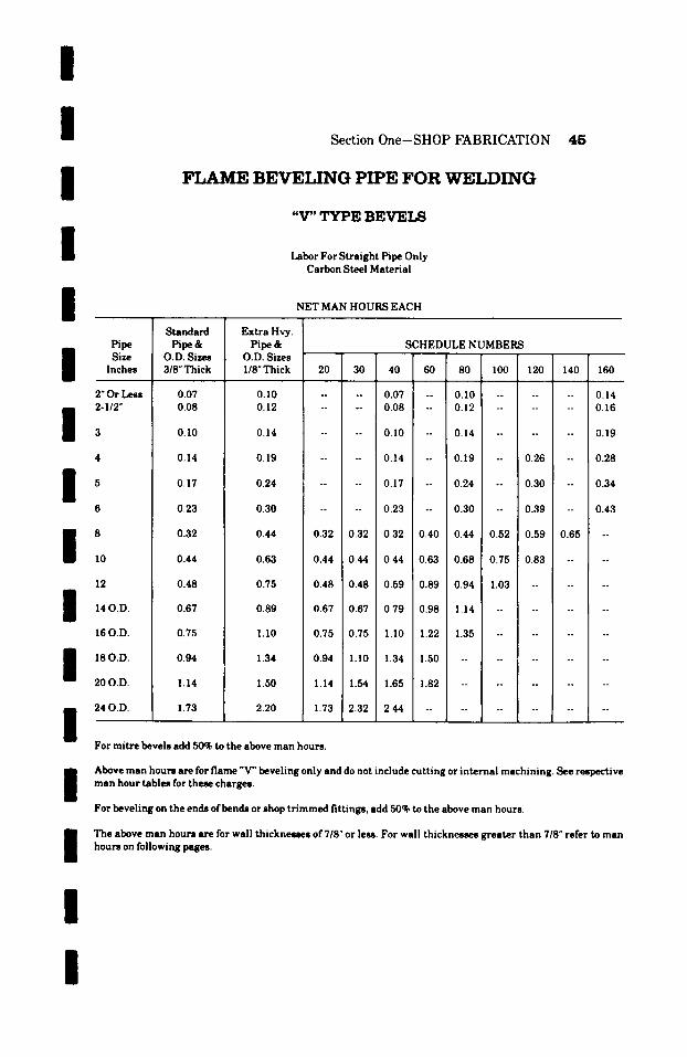
/ /
Section One-SHOP FABRICATION 4 5
/
I
F L A M E B E V E L I N G P I P E F O R W E L D I N G
"V" TYPE BEVELS
Labor For Straight Pipe Only Carbon Steel Material
I I
Pipe Size
Inches
2"Or L e ~ 2-1/2"
I 5
I 8 I0
12
I 14 O.D. 16 O.D.
I 18 O.D.
20 O.D.
i 24 O.D.
S t a n d a r d
P i p e & O.D. Sizes 3/8"Thick
0.07 0.08
0.10
0.14
0.17
0.23
0.32
0.44
Extra Hvy. Pipe&
O.D. Sizes 118" Thick
NET MAN HOURS EACH
SCHEDULE NUMBERS
20 30 40 60 80 100 120 140 160
0.10 . . . . 0.07 -- 0.10 . . . . . . 0.14 0.12 . . . . 0.08 -- 0.12 . . . . . . 0.16
0.14 . . . . 0. I0 -- 0.14 . . . . . . 0.19
0.19 . . . . 0.14 -- 0.19 -- 0.26 -- 0.28
0.24 . . . . 0.17 -- 0.24 -- 0.30 -- 0.34
0.48
0.67
0.75
0.94
1.14
1.73
0.30 . . . . 0.23 -- 0.30 -- 0.39 -- 0.43
0.44 0.32 0.32 0.32 0.40 0.44 0.52 0.59 0.65
0.63 0.44 0.44 0.44 0.63 0.68 0.75 0.83 --
0.75 0.48 0.48 0.59 0.89 0.94 1.03 . . . .
0.89 0.67 0.67 0.79 0.98 1.14 . . . . . .
1.10 0.75 0.75 1.10 1.22 1.35 . . . . . .
1.34 0.94 1.10 1.34 1.50 . . . . . . .
1.50 1.14 1.54 1.65 1.82 . . . . . . . .
2.20 1.73 2.32 2.44 . . . . . . . . .
For m i t r e bevels add 50% to the above m a n hours .
/ Above m a n hours a re for f lame "V" beve l ing only and do not include cu t t i ng or i n t e r n a l mach in ing . See respec t ive m a n hou r t ab les for these charges .
For beve l ing on the ends o f b e n d s or shop t r i m m e d f i t t ings , add 50% to the above m a n hours .
I The above m a n hours a re for wall t h i cknesses of 718" or less. For wall t h i cknesses g r e a t e r t h a n 718" refer to m a n hours on following pages.
I I
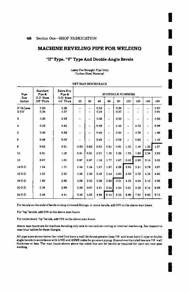
4 6 Section One--SHOP FABRICATION
MACHINE BEVELING PIPE FOR WELDING
"IT' Type, "V" Type And Double-Angle Bevels
Labor For Straight Pipe Only Carbon Steel Material
NET MAN HOURS EACH
I I I I I
l~pe Size
Inches
2"Or Le~ 2-I/2"
l0
12
14 O.D.
16 O.D.
18 O.D.
20 O.D.
24 O.D.
Standard Pipe &
O.D. Sizes 3/8" Thick
0.33 0.34
0.36
0.39
0.40
0.46
0.63
0.91
0.97
1.34
1.50
1.89
2.28
3.46
Extra Hvy. Pipe &
O.D. Sizes I/2" Thick
0.36 0.37
0.39
0.42
0.50
0.59
SCHEDULE NUMBERS
20 30 40 60 80 100 120 140 160
-- 0.33 -- I 0.36 . . . . . . 0.87 -- 0.34 -- 0.37 . . . . . . 0.91
0.36 -- 0.39 . . . . . . 0.93
0.39 -- 0.42 -- 0.72 -- 0.99
0.40 -- 0.50 -- 0.78 -- 1.06
0.46 -- 0.59 -- 0.83 -- 1 16
0.91 0.63 0.63 0.63 0.81 0.91 1.05 1.18 1.32 1.87
1.26
1.50
1.77
0.91 0.91 0.91 1.26 1.36 1.50 1.69 2.34 2.83
0.97 0.97 1.18 1.77 1.87 ~ 2 . 0 3 2.83 3.14 3.35
1.34 1.34 1.57 1.97 2.28 2.93 3.21 3.78 3.97
2.20 1.50 1.50 2.20 2.44 2.60 3.50 3.78 4.25 4.82
2.68 1.89 2.20 2.68 2.99 3.21 4.25 4.54 5.10 5.95
2.99
4.41
2.28 3.07 3.31 3.54 4.54 5.01 5.29 6.14 6.99
3.46 4.65 4.88 6['~'14 6.33 6.90 7.65 8.60 9.73 /
/ /
I I I I I For bevels on the ends of bends or shop tr immed fittings, or mitre bevels, add 50% to the above man hours.
For "lip" bevels, add 50q~ to the above man hours. m
For rolled down "lip" bevels, add 75q~ to the above man hours. I
Above man hours are for machine beveling only and do not include cutting or internal machining. See respective man hour tables for these charges, n
| All pipe sizes shown below the ruled line have a wall thickness greater than 7/8" and must have U-type or double angle bevels in accordance with ANSI and ASME codes for pressure piping. Sizes above the ruled line are 7/8' wall thickness or less. The man hours shown above the ruled line are for bevels as required for inert arc root pass welding. /
/

/
I / / /
Section One-SHOP FABRICATION 4 7
BEVET,TNG H E A V Y WALL PIPE FOR WET.PING
" U " T y p e O r D o u b l e A n g l e B e v e l s
Labor For Straight Pipe Only Carbon Steel Material
NET MAN HOURS EACH
I I I I
Nominal Pipe S=e
WALL THICKNESS IN INCHES
�9 750 1.00 1.25 1.50 1.75 2.00 2.25 2.50
3 1.54 1.57 . . . . . . . . . . 4 1.57 1.61 1.70 1.89 . . . . . . 5 -- 1.73 1.76 2.14 2.39 2.71 -- - 6 -- 1.86 2.02 2.39 2.71 2.96 3.40 -- 8 -- 1.95 2.29 2.65 3.09 3.34 3.72 4.35
10 . . . . 2.65 2.96 3.34 3.65 4.09 4.66 12 . . . . . . 3.34 3.59 4.09 4.54 5.10 14 . . . . . . 3.84 3.97 4.41 4.91 5.61 16 . . . . . . . 4.60 5.29 5.98 6.55 18 . . . . . . . . . 5.98 6.55 7.31 20 . . . . . . . . . . 6.55 7.31 8.25 22 . . . . . . . . . . . . . . 8.94 24 . . . . . . . . . . . . . . 10 .14
2.75 3.00 3.25 3.50 3.75 4.00 4.25 4.50
10 5.04 5.35 . . . . . . . . . 12 5.67 6.11 6 .55 7 .06 . . . . . . 14 6.24 6.74 7.06 8.00 8.60 9.39 -- 16 7.12 7.69 8.25 8.94 9.70 10.65 -- 18 8.00 8.60 9.39 10.14 10.96 12.16 -- 20 8.82 9.51 10.46 11.40 12.35 13.42 14.55
I 22 9.89 10.71 11.40 12.66 13.80 14.87 16.00 24 10.96 11.91 12.91 14.11 14.87 16.50 18.02
/ /
I /
4.75 5.00 5.25 5.50 5.75 6.00
20 16.69 17.70 18.90 19.91 21.10 22.17 22 18.39 19.59 20.66 21.80 22.99 24.25 24 21.29 22.43 23.81 25.20 26.46 27.91
For General Notes, see the bottom of pages ],5 and ],6.
~ 1 7 6
~ 1 7 6
~ 1 7 6
15.62 17.20 19.72
/
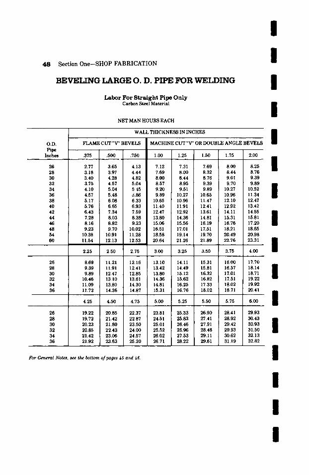
48 Section One--SHOP FABRICATION
BEVELING LARGE O. D. PIPE FOR WET.PING
Labor Fo r Straight Pipe Only Carbon Steel Material
NET MAN HOURS EACH
i l i I
O . V .
Pi~ Inches
26 28 30 32 34 36 38 40 42 44 46 48 54 60
WALL THICKNESS IN INCHES
FLAME CUT "V" BEVELS MACHINE CUT "V" OR DOUBLE ANGLE BEVELS /
.375 .500 .750 1.00 1.25 1.50 1.75 2.00 �9 --" '" /
$ 2.77 3.65 4.13 7.12 7.31 7.69 8.00 8.25 3.18 3.97 4.44 7.69 8.00 8.32 8.44 8.76 3.40 4.28 4.82 8.00 8.44 8.76 9.01 9.39 3.75 4.57 5.04 8.57 8.95 9.39 9.70 9.89 / 4.10 5.04 5. :15 9.20 9.51 9.89 10.27 10.52 ! 4.57 5.48 5.86 9.89 10.27 10.65 10.96 11.34 5.17 6.08 6.33 10.65 10.96 11.47 12.10 12.47 5.76 6.65 6 . 9 3 1 11.40 11.91 12.41 12.92 13.42 6.43 7.34 7.59 12.47 12.92 13.61 14.11 14.55 a 7.28 8.03 8.38 13.80 14.36 14.81 15.31 15.81 $ 8.16 8.82 9.23 15.06 15.56 16.19 16.76 17.20 9.23 9.70 10.02 16.51 17.01 17.51 18.21 18.65
10.38 10.91 11.28 18.58 19.14 19.70 20.49 20.98 11.54 12.13 12.53 �9 20.64 21.26 21.89 22.76 23.31 B
l 2.25 2.50 2.75 3.00 3.25 3.50 3.75 4.00
26 8.69 11.21 12.16 13.10 14.11 15.31 16.00 17.70 28 9.39 11.91 12.41 13.42 14.49 15.81 16.57 18.14 30 9.89 12.47 12.85 13.80 15.12 16.32 17.01 18.71 $ 32 10.46 13.10 13.61 14.36 15.62 16.82 17.51 19.22 34 11.09 13.80 14.30 14.81 16.25 17.33 18.02 19.92 36 11.72 14.36 14.87 15.31 16.76 18.02 18.71 20.41
�9 " �9 i $ 4.25 4.50 4.75 5.00 5.25 5.50 5.75 6.00 . .
26 19.22 20.85 22.37 23.81 25.33 26.90 28.41 29.93 28 19.72 21.42 22.87 24.51 25.83 27.41 28.92 30.43 30 20.23 21.80 23.50 25.01 26.46 27.91 29.42 30.93 32 20.85 22.43 24.00 25.52 26.96 28.48 29.93 31.50 34 21.42 23.06 24.57 26.02 27.53 29.11 30.62 32.13 36 21.92 23.63 25.20 26.71 28.22 29.61 31.19 32.82
For General Notes, see the bottom of pages ~5 and ~6.
I
I
i
I I

I I I I
Section One-SHOP FABRICATION 4 9
T H R E A D I N G P I P E - - I N C L U D I N G CUT
Labor for Cutting and Threading Only Carbon Steel Material
NET MAN HOURS EACH
Pipe
Inches
2" or less 2-1/2
4
5
8
10
12
14 O.D.
1 6 0 . D .
I 18 O.D.
20 O.D.
24 O.D.
Standard Pipe&
O.D. Sizes 3/8" Thick
0.17 0.23
0.25
0.36
0.46
0.59
0.82
1.17
1.30
1.75
2.01
2.50
3.00
4.39
E x t r a t tvy. P i p e &
O.D. Sizes 1/2" Thick
0.25 0.34
0.36
0.49
0.66
0.79
SCHEDULE N U M B E R S
20 30 40 60 80 100 120 140 160
0.17 -- 0.25 0.36 0.23 -- 0.34 0.40
0.25 -- 0.36 -- 0.49
0.36 -- 0.49 -- 0.71 0.76
0.46 -- 0.66 -- 0.77 0.91
0.59 -- 0.79 -- 1.00 1.14
1.14 0.82 0.82 0.82 , 1.07 1.14 1.39 1.55 1.73 2.02
1.56 1.17 1.17 1.17 1.56 1.79 2.07 2.19 2.61 3.09
2.07 1.30 1.30 1.75 2.33 2.46 2.69 3.09 3.51 3.71
2.26 1.75 1.75 2 . 2 6 2.50 2.87 3.26 3.51
2.92 2.01 2.01 2.92 3.14 3.51 3.71 4.13
3.51 2.50 3.09 3.51 3.71 4.13 4.59
3.00 4.00 4.81 5.22 5.50 --
4.39 6.13 6.50 6.72 7.09 --
4.00
5.84
I Above m a n hours a re for die cut IPS pipe t h r eads only.
For shop m a k e ~ n o f sc rewed f i t t ings use 50ck of the above man hours.
For t h r e a d i n g the ends of bonds, add 100~ to the above m a n hours.
/ / / /

50 Section One-SHOP FABRICATION
WET,bED CARBON STEEL A~FACHMENTS NET MAN HOURS PER LINEAL INCH
I I I
Thickness of Plate, etc. Inches
1/2 or less
3/4
1-1/4
1-1/2
1-3/4
** Layout and Flame Cutting per Lin. Inch
0.04
0.04
0.04
0.06
0.06
0.07
0.08
Fillet Welding per Lin. Inch
0.04
0.06
0.08
0.1
0.1
0.2
0.2
/ / / /
**Figure labor on basis of total lineal inches to be cut and fillet welded. Unlisted thicknesses take the next higher listing. Man hours do not include machining of bases, anchors, supports, lugs, etc. If preheating is required, add 100oh to the above man hours.
DRH,LING HO!,ES IN WET,bED A2~ACHMENTS Carbon Steel Material
MAN HOURS EACH
/ /
Thickness of HOLE SIZE Plates, Angles Etc. in Inches 3/4" and Smaller 7/8", l "and 1-1/8" 1-1/4", 1-1/2"and 2" 2-1/4" and 2-1/2"
I/2" or less 3/4
1 1-1/4 1-1/2 1-3/4
2 2-I/2
3 3-1/2
0.20 0.24
0.26 0.33 0.41 0.46
0.59 0.68
0.76 0.84
1.01
0.24 0.28
0.33 0.41 0.46 0.59
0.68 0.73
0.93 1.01
1.18
0.28 0.36
0.41 0.46 0.59 0.72
0.84 0.93
1.10 1.27
1.44
0.39 0.46
0.51 0.59 0.76 0.93
I.I0 1.35
I / /
1.52 i 1.78
2.03
Unlisted thicknesses of plate or sizes of holes take the next higher listing, i Ifholes are to be tapped--Add 33-1/3%. | Drilling of Sentinel, Safety or Tell Tale holes will be charged at .05 man hours.
The above man hours are for drilling holes in fiat carbon steel plate and structural shapes only.
For drilling holes in pipe or other contoured objects, perpendicular to contoured surface, add 10(O to the above i man hours. 8 For drilling holes in pipe or other contoured objects, oblique to contoured surface, add 175% to the above man hours.
/
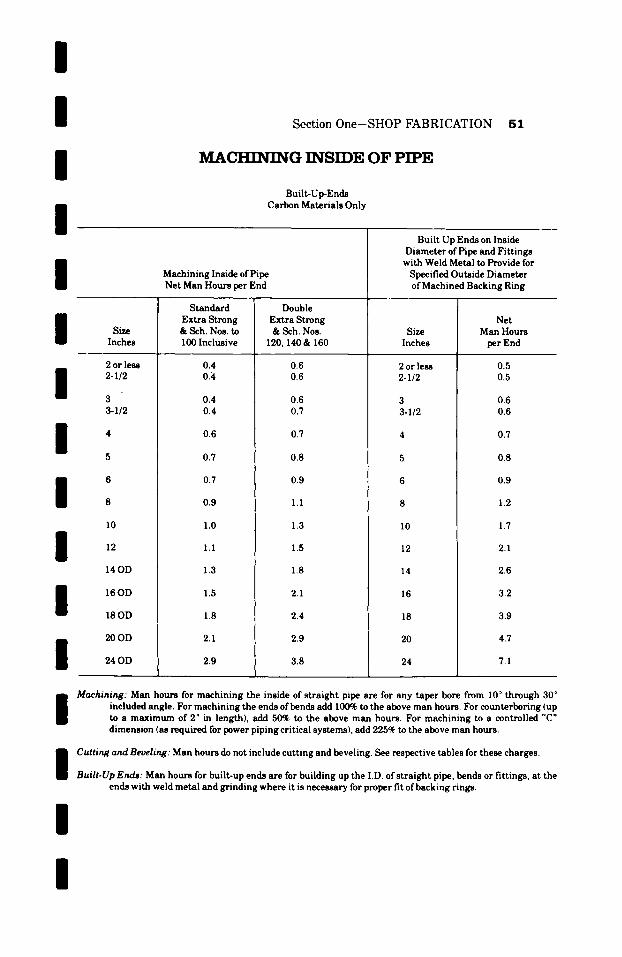
/ / / /
Section One-SHOP FABRICATION 51
MACHINING INSIDE OF PIPE
Built-Up-Ends Carbon Materials Only
I I Size
Inches
I I I 6
8
I I I
2 or less 2-I/2
3 3-I/2
10
12
14OD
16OD
18OD
20OD
24OD
Machining Inside of Pipe Net Man Hours per End
Standard Extra Strong & Sch. Nos. to 100 Inclusive
0.4 0.4
0.4 0.4
0.6
0.7
0.7
0.9
1.0
1.1
1.3
1.5
1.8
2.1
2.9
Double Extra Strong & Sch. Nos.
120,140 & 160
0.6 0.6
0.6 0.7
0.7
0.8
0.9
1.1
1.3
1.5
1.8
2.1
2.4
2.9
3.8
Built Up Ends on Inside Diameter of Pipe and Fittings with Weld Metal to Provide for Specified Outside Diameter of Machined Backing Ring
Size Inches
2 or less 2-1/2
3 3-I/2
I0
12
14
16
20
24
Net Man Hours per End
0.5 0.5
0.6 0.6
0.7
0.8
0.9
1.2
1.7
2.1
2.6
3.2
3.9
4.7
7.1
i Machining: Man hours for machining the inside of straight pipe are for any taper bore from I0 ~ through 30 ~ included angle. For machining the ends of bends add 100% to the above man hours. For counterboring (up to a maximum of 2 ~ in length), add 50% to the above man hours. For machining to a controlled "C" dimension (as required for power piping critical systems), add 225~ to the above man hours.
I Cutting and Beveling: Man hours do not include cutting and beveling. See respective tables for these charges.
Built.Up Ends: Man hours for built-up ends are for building up the I.D. of straight pipe, bends or fittings, at the ends with weld metal and grinding where it is necessary for proper fit of backing rings.
I I
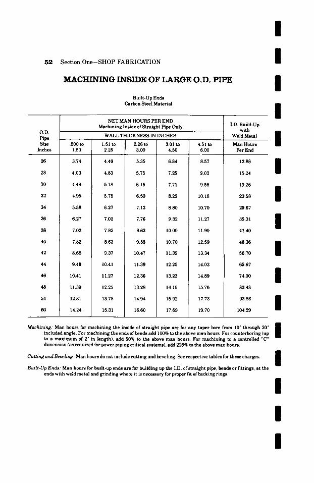
52 Section One-SHOP FABRICATION
MACHINING INSIDE OF LARGE O.D. PIPE
Built-Up Ends Carbon Steel Material
I I I I
O.D. Pipe Size
Inches
26
28
30
32
34
36
38
40
42
44
46
48
54
60
NET MAN HOURS PER END Machining Inside of Straight Pipe Only
WALL THICKNESS IN INCHES
.500 to 1.50
3.74
4.03
4.49
4.95
5.58
6.27
7.02
7.82
8.68
9.49
10.41
11.39
12.81
14.24
1.51 to 2.25
4.49
4.83
5.18
5.75
6.27
7.02
7.82
8.63
9.37
10.41
11.27
12.25
13.78
15.31
2.26 to 3.00
5.35
5.75
6.15
6.50
7.13
7.76
8.63
9.55
10.47
11.39
12.36
13.28
14.94
16.60
3.01 to 4.50
6.84
7.25
7.71
8.22
8.80
9.32
10.00
10.70
11.39
12.25
13.23
14.15
15.92
17.69
4.51 to 6.00
8.57
9.03
9.55
10.18
10.70
11.27
11.90
12.59
13.34
14.03
14.89
15.76
17.73
19.70
I.D. Build-Up with
Weld Metal
Man Hours Per End
/ 12.88 m
15.24
19.26
23.58
29.67
35.31
41.40
I I
56.70
65.67
74.00
83.43
93.86
104.29
I I m
Machining: Man hours for machining the inside of straight pipe are for any taper bore from 10 ~ through 30 ~ included angle. For machining the ends of bends add 100% to the above man hours. For counterboring (up | to a maximum of 2" in length), add 50% to the above man hours. For machining to a controlled "C" dimension (as required for power piping critical systems), add 225% to the above man hours.
Cutting and Beveling: Man hours do not include cutting and beveling. See respective tables for these charges.
Built-Up Ends: Man hours for built-up ends are for building up the I.D. of straight pipe, bends or fittings, at the ends with weld metal and grinding where it is necessary for proper fit of backing rings.
I I I I
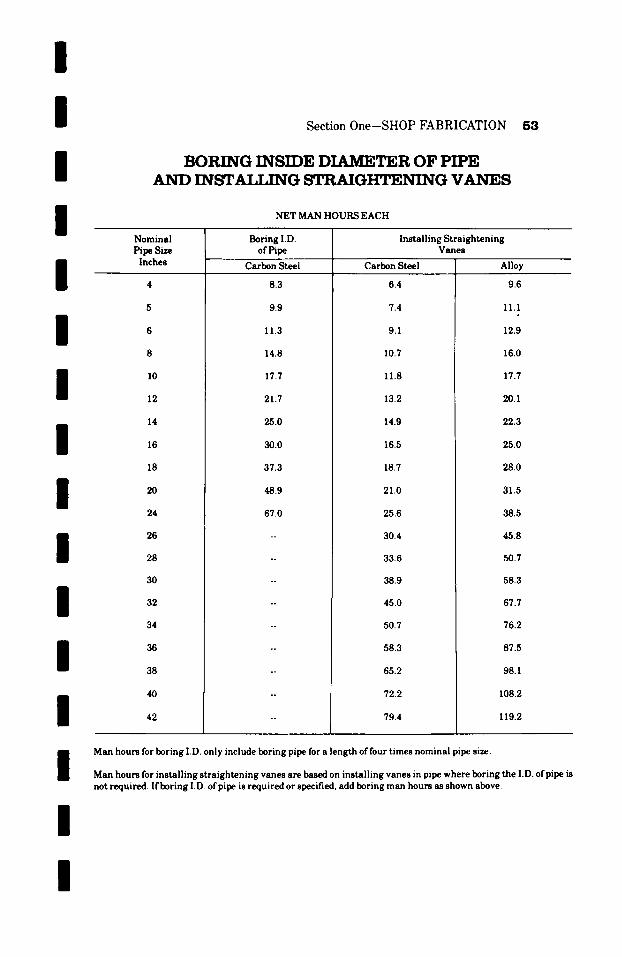
/ / /
I
Section One-SHOP FABRICATION 5,3
BORING INSIDE DIAMETER OF PIPE A N D INSTALLrNG STRAIGttT~:NING V A N E S
NET MAN HOURS EACH
/ / /
l / / / /
l
Nominal Pipe Size
Inches
12
14
18
20
24
26
28
30
32
34
36
38
40
42
Boring I.D. of Pipe
Carbon Steel
8.3
9.9
11.3
14.8
17.7
21.7
25.0
30.0
37.3
48.9
67.0
Installing Straightening Vanes
Carbon Steel
6.4
7.4
9.1
10.7
11.8
13.2
14.9
16.5
18.7
21.0
25.6
30.4
33.6
38.9
45.0
50.7
58.3
65.2
72.2
79.4
Alloy
9.6
11.1
12.9
16.0
17.7
20.1
22.3
25.0
28.0
31.5
38.5
45.8
50.7
58.3
67.7
76.2
87.5
98.1
108.2
119.2
/
l
Man hours for boring I.D. only include boring pipe for a length of four times nominal pipe size.
Man hours for installing straightening vanes are based on installing vanes in pipe where boring the I.D. ofpipe is not required. If boring I.D. ofpipe is required or specified, add boring man hours as shown above.
l

K4 Section One-SHOP FABRICATION
INST/t!ff.ING FIL)W NOZZLES Holding Ring Type
Carbon Steel and Alloy Materials
NET MAN HOURS EACH
l I I I
Pipe S~e
Inches
I0
12
140.D.
16 O.D.
180.D.
20 O.D.
24 O.D.
Flow Nozzles Carbon Steel
32.9
35.7
39.8
46.8
53.4
60.2
65.8
74.2
83.7
94.1
118.9
Alloy
38.4
41.4
46.1
53.0
61.6
70.0
77.3
87.6
99.3
113.3
144.7
Pipe O.D. Inches
26
28
30
32
34
36
38
40
42
Flow Nozzles Carbon Steel
140.3
160.7
184.2
210.6
240.4
270.4
303.0
339.4
380.1
Alloy
168.4
188.1
211.8
239.2
268.0
302.9
342.4
386.9
407.3
/ / /
I / /
Man hours include internal machining and nozzle installation.
For installing welding type flow nozzles, add for the bevels, butt weld, butt weld preheat, and any other labor operation or non-destructive testing operation required for the butt weld. See respective tables for these charges.
/
I / / /
t

I I Section One-SHOP FABRICATION
/
/
/
/
/
/
I / / /
/
/ /
P R E H E A T I N G B u T r WET,DS AND ANY TYPE OF FLANGE WET,DS
Labor Only
Carbon Steel, or Alloy Materials For Temperatures Up To 400 ~F.
NET MAN HOURS EACH
S~e Ins.
2 2-I/2
3 3-I/2
10
12
14 OD
16 OD
18 OD
2 0 0 D
24 OD
Standard Pipe
& OD Sizes 3/8"Thick
0.2 0.3
0.4 0.4
0.5
0.6
0.7
0.8
1.1
1.3
1.6
1.9
2.2
2.6
3.1
Extra Heavy Pipe & OD Sizes I/2"Thick
SCHEDULE NUMBERS
20 30 40 60 80 1 1 0 0 120 140 160
0.3 0.2 -- 0.3 . . . . . . 0.4 0.4 0.3 -- 0.4 . . . . . . 0.5
0.5 0.4 -- 0.5 0.6 0.5 0.4 -- 0.5 0.8
0.6 0.5 -- 0.6 -- 0.8 0.8
0.8 0.6 -- 0.8 -- 0.8 0.9
0.9 0.7 -- 0.9 -- I.I -- 1.3
I . I 0.8 0.8 0.8 I . I I . I 1.5 1.6 2.0 2.1
1.5 I.I 1.1 1.1 1.5 1.7 2.0 2.3 2.8 3.2
1.7 1.3 1.3 1.6 1.9 2.4 2.8 3.2 3.7 4.5
2.1 1.6 1.6 1.9 2.5 3.0 3.7 4.2 4.9 5.6
2.8 1.9 1.9 2.5 3.2 3.8 4.6 5.1 6.2 7.2
3.0 2.2 2.6 3.5 4.2 5.1 5.9 6.7 7.2 8.9
3.5 2.6 3.5 4.4 5.3 6.3 7.4 8.3 9.4 10.9
4.2 3.1 4.5 5.4 6.6 7.9 8.8 9.9 11.3 12.9 . = .
Pipe Thickness: The wall thickness of the material determines the man hours that will apply. For preheating of double extra strong material, use Schedule 160 man hours.
Mitre Welds: For preheating of mitre welds, add 50% to above man hours.
Man Hours: Man hours for preheating are additional to charges for welding operations.
Preheating: For preheating to temperatures above 400~ but not exceeding 600~ add 100~ to the above man hours.
I
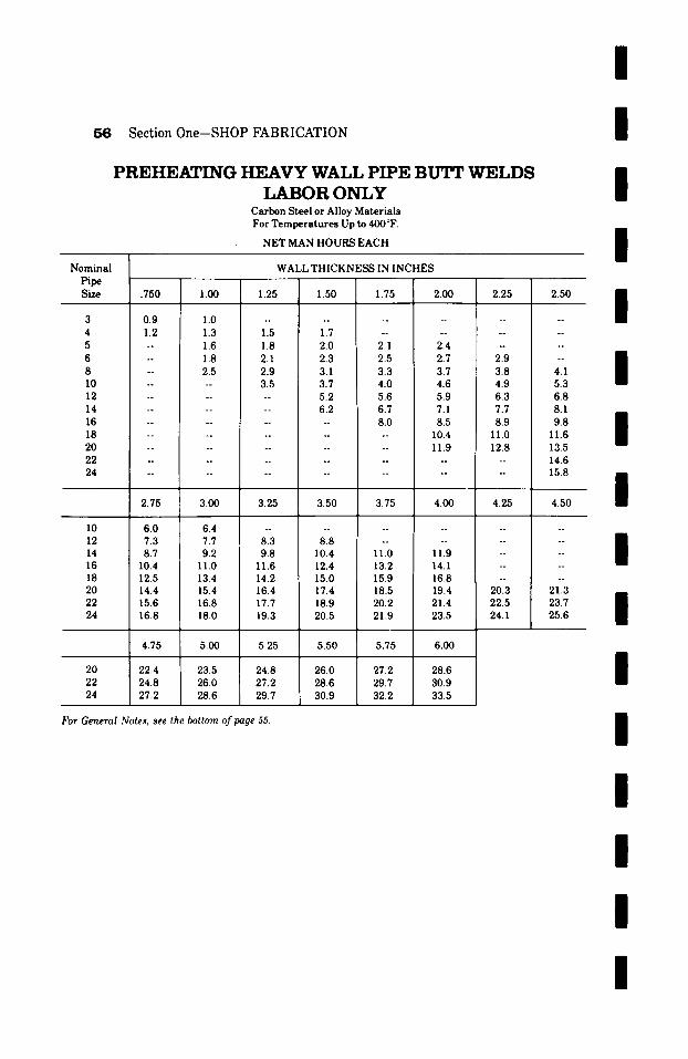
I 56 Section One-SHOP FABRICATION
P R E H E A T I N G H E A V Y WALL PIPE BUTT W E L D S L A B O R O N L Y
Carbon Steel or Alloy Mater ia ls For Tempera tu re s Up to 400 ~
N E T MAN H O U R S E A C H
i
i /
Nomina l Pipe SLze
WALL T H I C K N E S S IN I N C H E S
.750 1.00 1.25 1.50 1.75 2.00 2.25 2.50
B | �9
3 0.9 1.0 . . . . . . . . . . . . 4 1.2 1.3 1.5 1.7 . . . . . . . . 5 -- 1.6 1.8 2.0 2.1 2.4 . . . . 6 -- 1.8 2.1 2.3 2.5 2.7 2.9 --
i 8 -- 2.5 2.9 3.1 3.3 3.7 3.8 4.1 10 . . . . 3.5 3.7 4.0 4.6 4.9 5.3 12 . . . . . . 5.2 5.6 5.9 6.3 6.8 14 . . . . . . 6.2 6.7 7.1 7.7 8.1 16 . . . . . . . . 8.0 8.5 8.9 9.8 i
i 18 . . . . . . . . . . 10.4 11.0 11.6 20 . . . . . . . . . . 11.9 12.8 13.5 22 . . . . . . . . . . . . . . 14.6 24 . . . . . . . . . . . . . . 15.8
m 2.75 3.00 3.25 3.50 3.75 4.00 4.25 4.50 i
10 6.0 6.4 . . . . . . 12 7.3 7.7 . . . . . . 14 8.7 9.2 11.0 11.9 -- 16 10.4 11.0 13.2 14.1 -- 18 12.5 13.4 15.9 16.8 -- 20 14.4 15.4 18.5 19.4 20.3 22 15.6 16.8 20.2 21.4 22.5 24 16.8 18.0 21.9 23.5 24.1
4.75 5.00
20 22.4 23.5 22 24.8 26.0 24 27.2 28.6
8.3 8.8 9.8 10.4
11.6 12.4 14.2 15.0 16.4 17.4 17.7 18.9 19.3 20.5
5.25 5.50 5.75 6.00
24.8 26.0 27.2 28.6 27.2 28.6 29.7 30.9 29.7 30.9 32.2 33.5
For General Notes, see the bottom of page 55.
o o
~ 1 7 6
o ~
o ~
~ 1 7 6
21.3 23.7 25.6
/ /
i
i
i
i
i
i
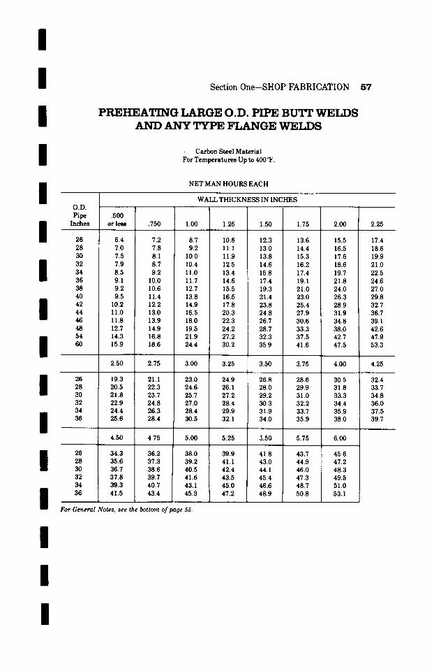
I i /
i /
Section One-SHOP FABRICATION 57
P R E H E A T I N G LARGE O.D. PIPE B D T r WrET,]'}S A N D A N Y TYPE F L A N G E ~T,~
Carbon Steel Material For Temperatures Up to 400 ~F.
NET MAN HOURS EACH
/
i / / /
i /
i /
i
WALL THICKNESS IN INCHES O . D .
Pipe .500 Inches or less .750 1.00 1.25 1.50
26 6.4 7.2 8.7 10.6 12.3 28 7.0 7.8 9.2 11.1 13.0 30 7.5 ! 8.1 10.0 11.9 13.8 32 7.9 8.7 10.4 12.5 14.6 34 8.5 9.2 11.0 13.4 15.8 36 9.1 10.0 11.7 14.6 17.4 38 9.2 10.6 12.7 15.5 19.3 40 9.5 11.4 13.8 16.5 21.4 42 10.2 12.2 14.9 17.8 23.8 44 11.0 13.0 16.5 20.3 24.8 46 11.8 13.9 18.0 22.3 26.7 48 12.7 14.9 19.5 24.2 28.7 54 14.3 16.8 21.9 27.2 32.3 60 15.9 18.6 24.4 30.2 35.9
1.75
13.6 14.4 15.3 16.2 17.4 19.1 21.0 23.0 25.4 27.9 30.6 33.3 37.5 41.6
2.50 2.75 3.00 3.25 3.50 3.75
26 19.3 21.1 23.0 24.9 26.8 28.6 28 20.5 22.3 24.6 26.1 28.0 29.9 ~M) 21.8 23.7 25.7 27.2 29.2 31.0 i 32 ~ 22.9 24.8 27.0 28.4 30.3 32.2 34 i 24.4 26.3 28.4 29.9 31.9 33.7 36 25.6 28.4 30.5 32.1 34.0 35.9
4.50 4.75 5.00 5.25 5.50 5.75
26 34.3 36.2 38.0 39.9 41.8 43.7 28 35.6 37.3 39.2 41.1 43.0 44.9 30 36.7 38.6 40.5 42.4 44.1 46.0 32 37.8 39.7 41.6 43.5 45.4 47.3 34 39.3 40.7 43.1 45.0 46.6 48.7 36 41.5 43.4 45.3 47.2 48.9 50.8
2.00
15.5 16.5 17.6 18.6 19.7 21.8 24.0 26.3 28.9 31.9 34.8 38.0 42.7 47.5
4.00
30.5 31.8 33.3 34.4 35.9 38.0
6.00
45.6 47.2 48.3 49.5 51.0 53.1
2.25
17.4 18.6 19.9 21.0 22.5 24.6 27.0 29.8 32.7 36.7 39.1 42.6 47.9 53.3
4.25
32.4 33.7 34.8 36.0 37.5 39.7
For General Notes, see the bottom of page 55.
I
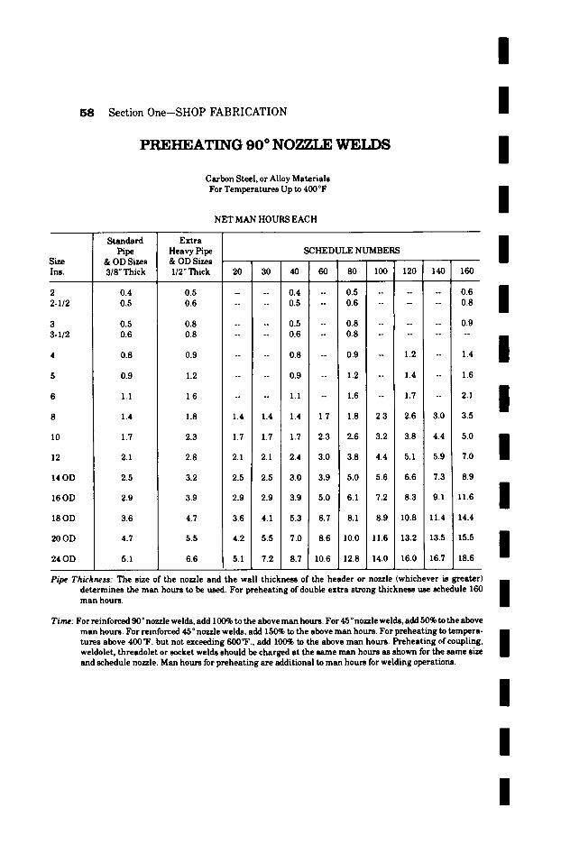
/
5 8 Section One-SHOP FABRICATION
P R E H E A T I N G 9 0 ~ NOT, ZI.E W E L D S
Carbon Steel, or Alloy Materials For Temperatures Up to 400~
NET MAN HOURS EACH
I I I
Size Ins.
2 2-I/2
3 3-I/2
10
12
14OD
16OD
18OD
20OD
24 OD
Standard Pipe
& OD Sizes 318"Thick
0.4 0.5
0.5 0.6
0.8
0.9
1.1
1.4
1.7
2.1
2.5
2.9
3.6
4.7
5.1
Extra Heavy Pipe & OD Sizes l /2"Thick
SCHEDULE NUMBERS
20 30 40 60 80 1 0 0 ' 1 2 0 1 4 0 1 1 6 0 II n
0.5 ~ ~176 0.4 *~ 0.5 . . . . . 0.6
0 . 6 . . . . 0 . 5 - 0 . 6 . . . . . 0 . 8 II 0.8 .... 0.5 -- 0.8 . . . . . . 0.9 0.8 .... 0.6 -- 0.8 . . . . . . . .
0.9 .... 0.8 -- 0.9 - 1.2 -- 1.4
1.2 .... 0.9 -- 1.2 -- 1.4 -- 1.6
1.6 .... I.I -- 1.6 -- 1.7 -- 2.1
1.8 1.4 1.4 1.4 1.7 1.8 2.3 2.6 3.0 3.5
2.3 1.7 1.7 1.7 2.3 2.6 3.2[3.8 4.4 5.0
2.8 2.1 2.1 2.4 3.0 3.8 4.4 5.1 5.9 7.0
3.2 2 . 5 2.5 3.0 3.9 5.0 5.6 6.6 7.3 8.9
3.9 2.9 2.9 3.9 5.0 6.1 7.2 8.3 9.1 11.6
4.7 3.6 4.1 5.3 6.7 8.1 8.9 10.8 11.4 14.4
5.5 4.2 5.5 7.0 8.6 I0.0 11.6 13.2 13.5 15.5
6.6 5.1 7.2 8.7 10.6 12.8 14.0 16.0 16.7 18.6
I I I I I
Pipe Thickness: The size of the nozzle and the wall thickness of the header or nozzle (whichever is greater) n determines the man hours to be used. For preheating of double extra strong thickness use schedule 160 man hours. |
Time: For reinforced 90 o nozzle welds, add 100% to the above man hours. For 45 o nozzle welds, add 50% to the above man hours. For reinforced 450 nozzle welds, add 150% to the above man hours. For preheating to tempera- n tures above 400~F. but not exceeding 600~ add 100% to the above man hours. Preheating of coupling, I weldolet, threadolet or socket welds should be charged at the same man hours as shown for the same size and schedule nozzle. Man hours for preheating are additional to man hours for welding operations.
I I I
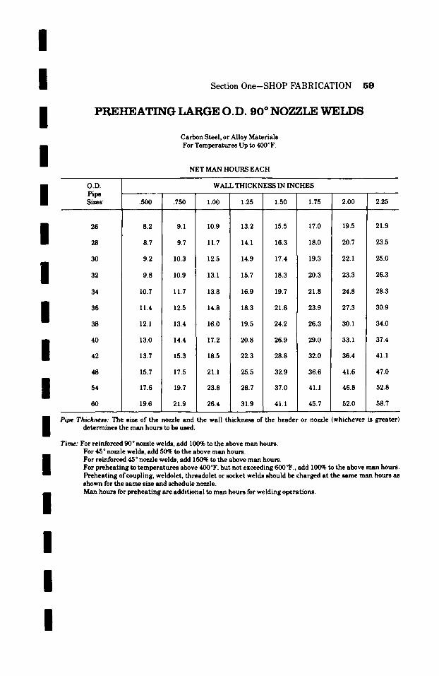
l / /
/
S e c t i o n 0 n e - S H O P F A B R I C A T I O N 5 9
P R E H E A T I N G L A R G E O.D. 9 0 ~ N O Z Z L E W E I . D S
Carbon Steel, or Alloy Materials For Temperatures Up to 400~
NET MAN HOURS EACH
/
/
/
/ / / / /
/
O.D. Pipe Sizes-
26
28
30
32
34
36
38
40
42
48
54
60
WALL THICKNESS IN INCHES
�9 500 .750 1.00 1.25 1.50 1.75 2.00 2.25
8.2 10.9 13.2 15.5 17.0 19.5 21.9
8.7 11.7 14.1 16.3 18.0 20.7 23.5
9.2 12.5 14.9 17.4 19.3 22.1 25.0
9.8 13.1 15.7 18.3 20.3 23.3 26.3
10.7 13.8 16.9 19.7 21.8 24.8 28.3
11.4 14.8 18.3 21.8 23.9 27.3 30.9
12.1 16.0 19.5 24.2 26.3 ! 30.1 34.0
13.0 17.2 20.8 26.9 29.0 33.1 37.4
13.7 18.5 22.3 28.8 32.0 36.4 41.1
15.7 21.1 25.5 32.9 36.6 41.6 47.0
17.6 23.8 28.7 37.0 41.1 46.8 52.8
19.6 26.4 31.9 41.1 45.7 52.0 58.7
Pipe Thickness: The size of the nozzle and the wall thickness of the header or nozzle (whichever is greater) determines the man hours to be used.
Time: For reinforced 90 ~ nozzle welds, add 100% to the above man hours. For 45 ~ no~le welds, add 50% to the above man hours. For reinforced 45 ~ nozzle welds, add 150% to the above man hours. For preheating to temperatures above 400~ but not exceeding 600~F., add 100% to the above man hours. Preheating of coupling, weldolet, threadolet or socket welds should be charged at the same man hours as shown for the same size and schedule nozzle. Man hours for preheating are additional to man hours for welding operations.
I I I

I I f )CAL STRESS RELr~,VING
Gas or Electric Method--Butt Welds--Nozzle Welds or Any Type of Flange Welds Carbon Steel Materials Temperatures to 1400~
NET MAN HOURS EACH
I I
~IZe
Ins.
2 2-1/2
3 3-1/2
10
12
14OD
16OD
18 OD
2 0 0 D
24OD
Standard Pipe
a r uu ~ lZe8
3 / 8 " T h i c k
2.3 2.4
2.5 2.6
2.6
3.0
3.2
3.6
Extra Heavy Pipe SCHEDULE NUMBERS a ; uu ~ i ze8 - -
1/2" Thick 20 30 40 60 80 100
2.4 . . . . 2.3 -- 2.4 . . . . . 2.6 2.5 . . . . 2.4 -- 2.5 . . . . . . 2.7
I B
2.6 - -- 2.5 -- 2.6 . . . . . 3.0 2.7 . . . . 2.6 -- 2.7 . . . . . 3.3 m
3.0 . . . . 2 . 6 -- 3.0 - 3.1 -- 3.4
3.2 . . . . 3.0 -- 3.2 -- 3.5 -- 3.7
3.9
4.3
4.7
5.0
5.4
5.6
6.0
3.6 . . . . 3.2 -- 3.6 -- 3.7 -- 4.3
4.0 3.6 3.6 3.6 3.7 4.0 4.3 4.5 4.7 5.0
4.3 3.9 3.9 3 . 9 ! 4 . 3 4.5 4.8 5.0 5.3 5.7
4.7 4.3 4.3 4.5 4.9 5.1 5.5 5.8 6.0 6.3
5.0 4.7 4.7 5.0 5 . 3 r 5 . 7 6.0 6.4 6.7 7.0
5.4 5.0 5.0 5.4 5.8 6.1 6.6 6.8 7.2 7.8
7.4 7.8 8.6
8.1 8.5 9.4
5.8 5.4 5.6 5.8 6.2 6.6 7.0
5.9 5.6 5.8 6.2 6.6 7.0 7.8
6.2 6.0 6.4 6.8 ! 7.2 I 7.8 8.6 8.9 9.5 10.6
I
I
I I I Pipe Thicl~wss: F o r S t r e s s r e l i e v i n g but t we lds and f lange we lds , the wal l t h i c k n e s s of the p ipe
d e t e r m i n e s the man hour s tha t wi l l apply . F o r s t r e s s r e l i e v i n g nozz l e we lds , the s i z e and t h i c k n e s s of the h e a d e r to which the n o z z l e is a t t a c h e d d e t e r m i n e s the man h o u r s tha t wi l l m apply . F o r loca l s t r e s s r e l i e v i n g of double e x t r a s t r o n g m a t e r i a l , u se Schedu le 160 man I h o u r s .
Man Hours: The total man hours for stress relieving shall be determined as follows: (1) By computing the total of all welds contained in the complete requirement figure on the basis of local
stress relieving unit man hours; (2) By totaling all pieces included in the complete requirement which can be full furnace stress relieved as
units, classifying them in their applicable groups, and computing the total man hours. Whichever of these two methods develops the lower man hours should be used in determining the man hours for stress relieving.
Valves: S t r e s s r e l i e v i n g may be done by the l oca l s t r e s s r e l i e v i n g p r o c e s s , o r , u n l e s s v a l v e s have been welded into the a s s e m b l y , the c o m p l e t e f a b r i c a t e d a s s e m b l y may be full f u r n a c e s t r e s s r e l i e v e d as a unit.
I
I The s t r e s s r e l i e v i n g of but t we lds jo in ing v a l v e s to f a b r i c a t e d a s s e m b l i e s m u s t be man i hou red as the man hou r s c o v e r i n g l o c a l s t r e s s r e l i e v i n g , even though a d j a c e n t a s s e m b l i e s | can be full f u r n a c e s t r e s s r e l i e v e d a s a unit .
Code Requirements: All we lds in p ip ing m a t e r i a l s hav ing a wal l t h i c k n e s s of 3 / 4 " or g r e a t e r m u s t be s t r e s s r e l i e v e d to comply wi th the r e q u i r e m e n t s of the A. S. A. Code for P r e s s u r e P ip ing . Man h o u r s shown below the r u l e d l ine . in the a b l e s c h e d u l e c o v e r s i z e s having a wa l l t h i c k n e s s of 3 / 4 " o r g r e a t e r . B
I
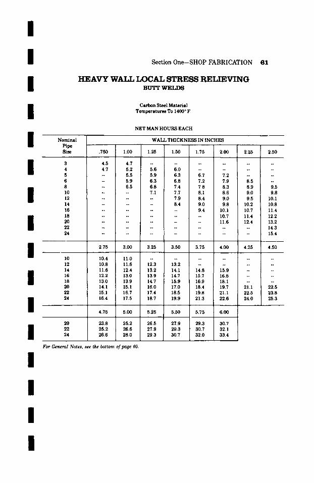
/
/ /
/
Section One-SHOP FABRICATION 61
HEAVY WALL I f )CAL STRESS RELIEVING BU'FF WELDS
Carbon Steel Ma te r i a l T e m p e r a t u r e s To 1400 ~ F.
NET MAN HOURS EACH
N o m i n a l W A L L T H I C K N ~ IN I N C H E S Pipe " " 1 " Size .750 1.00 1.25 1.50 1.75 2.00 2.25 2.50
! 9 J i 6 J
3 4 . 5 4 . 7 . . . . . . . . . . .
4 4 . 7 5 . 2 5 . 6 6 . 0 . . . . . . .
5 -- 5.5 5.9 6.3 6.7 7.2 -- - 6 - 5.9 6.3 6.8 7.2 7.9 8.5 -- 8 - 6.5 6.8 7.4 7.8 8.3 8.9 9.5 10 - -- 7.1 7.7 8.1 8 .6 9.0 9 .8 12 . . . . . . 7.9 8.4 9.0 9.5 10.1 14 . . . . 8.4 9.0 9.8 10.2 10.8 16 . . . . . . . 9.4 10.1 10.7 11.4
I 18 . . . . . . . 10.7 11.4 12.2 20 . . . . . . . . . 11.6 12.4 13.2 22 . . . . . . . . . . . 14.3 24 . . . . . . . . . . . . 15.4
/ / /
2.75 3.00 3.25 3.50 3.75 4.00 4.25 4.50
I0 10.4 I I . 0 . . . . . . . . . . . 12 10.8 11.6 12.3 13.2 . . . . . . . 14 11.6 12.4 13.2 14.1 14.8 15.9 - -- 16 12.2 13.0 13.9 14.7 15.7 16.8 . . . . 18 13.0 13.9 14.7 15.9 16.9 18.1 . . . . 20 14.1 15.1 16.0 17.0 18.4 19.7 21.1 22.5 22 15.1 16.7 17.4 18.5 19.8 21.1 22.5 23.8 24 16.4 17.5 18.7 19.9 21.3 22.6 24.0 25.3
4.75 5.00 5.25 5.50 5.75 6.00
20 23.8 25.2 26.5 27.9 29.3 30.7 I 22 25.2 26.6 27.9 29.3 30.7 32.1
24 26.6 28.0 29.3 30.7 32.0 33.4
For General Notes, see the bottom @page 60.
I
I
I
I

/
6 2 Section One-SHOP FABRICATION
LARGE O.D. LOCAL STRESS RELIEVING Butt Welds, Nozzle Welds or Any Type of Flange Weld
Carbon Steel Material Temperatures to 1400 ~ F.
NET MAN HOURS EACH
O . D .
I~pe Size
WALL THICKNESS IN INCHES
�9 375 .500 .750 1.00 1.25 1.50 1.75 I 2.00 I 2.25
26 7.9 8.5 9.8 10.3 11.0 12.3 14.2 18.5 28 8.3 9.1 10.6 11.0 12.0 13.2 15.4 19.9 30 9.0 9.8 11.4 12.1 12.8 14.5 16.7 21.4 32 9.8 10.7 12.4 13.0 13.7 15.7 18.1 23.0 34 10.8 11.7 13.5 14.1 14.9 17.0 19.6 24.5 36 11.8 12.8 14.8 15.7 16.8 18.7 21.3 26.6 38 12.8 14.0 16.3 17.4 18.8 20.8 23.5 29.1 40 14.0 15.3 17.9 19.4 21.1 23.1 25.8 31.7 42 15.5 16.9 19.7 21.4 23.7 25.7 28.3 34.5 44 17.3 18.7 21.5 23.5 25.8 28.3 31.1 37.2 46 19.0 20.5 23.4 26.0 28.4 31.3 34.2 40.4 I 48 21.2 22.6 25.4 28.4 31.1 34.2 37.3 43.3 54 24.8 25.4 28.6 32.0 35.0 38.5 42.0 48.7 60 26.4 28.2 31.8 35.5 38.9 42.8 46.6 55.3
2.50 2.75 3.00 3.25 3.50 3.75 4.00 I 4.25 I 4.50
26 20.7 23.0 25.3 27.6 29.9 32.2 34.5 I 36.8 I 39.1 28 22.2 24.5 26.8 29.1 31.4 33.7 36.0 I 38.3 I 40.5 30 23.7 26.0 28.3 30.6 32.9 35.1 37.4 I 39.7 I 42.0 32 25.3 27.6 29.8 32.1 34.4 36.7 39.0 I 41.3 I 43.6 34 26.8 29.1 31.4 33.0 36.0 38.3 40.6 I 42.9 I 45.2 36 28.9 31.2 32.4 35.1 38.1 40.4 42.7 I 45.0 I 47.3
4.75 5.00 5.25 5.50 5.75 6.00
43.7 45.9 48.2 50.5 52.8 45.1 47.4 49.7 52.0 54.3 46.6 48.9 51.1 53.4 55.7 48.2 50.5 52.7 55.0 57.3 49.8 52.1 54.3 56.6 58.9 51.8 54.1 56.4 58.7 61.0
26 41.4 28 42.8 30 44.3 32 45.9 34 47.5 36 49.9
For General Notes, see the bottom of page 60.
I
I
I
I
I
I
I I
I
I
I
I
I
I
I

I
I I I
Section One-SHOP FABRICATION
F U L L F U R N A C E S T R E S S R E L I E V I N G A N D H E A T I N G T R E A T M E N T
Carbon Steel and Alloy Mater ia ls
/ NET MAN HOURS
/
/
Fahrenhei t Tempera tu re
0 ~ to 1250 ~ Inclusive . . . . . . . . . . . . . . . . . . . . .
1251 ~ to 1400 ~ Inclusive . . . . . . . . . . . . . . . . . . . .
1401 ~ to 1700 ~ Inclusive . . . . . . . . . . . . . . . . . . . .
1701 ~ to 2200 ~ Inclusive . . . . . . . . . . . . . . . . . . . .
P e r Hundred Pounds
0.3
0 .4
0.7
1.1
/ / / / /
Exposed sec t ions of p ieces too large to be placed ent i re ly within the furnace will be included in subsequent furnace heat or heats until all pa r t s of the piece have been s t r e s s re l ieved or heat t rea ted . To calculate the man hours for this operaUon use: total weight of fabr icated piece Umes man hours pe r pound depending on t empera tu re , t imes total number of Umes piece must be heated to get full coverage.
Quenching is included in the above man hours. Mater ia ls to be quenched af ter annealing must not exceed ove r -a l l furnace dimension.
/ [
I /
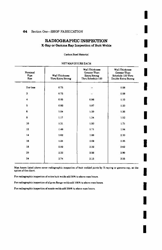
/
Section 0ne--SHOP FABRICATION
RADIOGRAPHIC INSPECTION X-Ray or Gamma Ray Inspection of Butt Welds
Carbon Steel Material
NET MAN HOURS EACH
I I I
Nominal Pipe Size
2 or less
10
12
14
16
18
20
24
Wall Thickness Thru Extra Strong
0.75
0.75
0.85
0.93
1.04
1.17
1.31
1.49
1.62
1.81
2.02
2.22
2.74
Wall Thickness Greater Than Extra Strong
Thru Schedule 120
0.98
1.07
1.20
1.34
1.50
1.71
1.86
2.08
2.32
2.56
3.15
Wall Thickness m Greater Than
Schedule 120 Thru Double Extra Strong
0.98
0.98
1.10
1.20
1.36
1.52
1.71
1.94
2.10
2.35
2.62
2.90
3.55
/
/
I / / /
Man hours listed above cover radiographic inspection of butt welded joints by X-raying or gamma-ray, at the option of the client, n
m For radiographic inspection of mitre butt welds add 50% to above man hours.
For radiographic inspection of slip-on flange welds add 100% to above man hours.
| For radiographic inspection of nozzle welds add 200% to above man hours.
I
I /
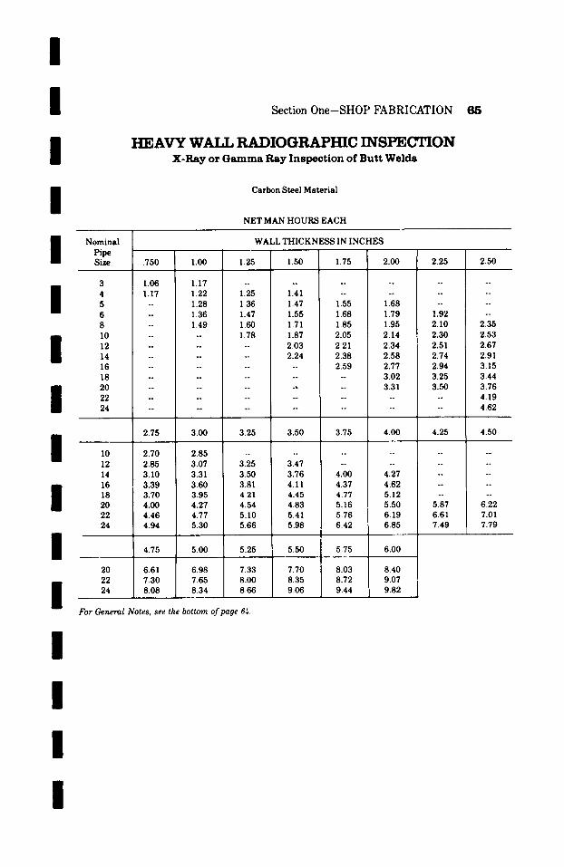
I I I I
Section One-SHOP FABRICATION 85
HEAVY WA T.I. RADIOGRAPHIC INSPECTION X - R a y o r G a m m a R a y I n s p e c t i o n o f B u t t W e l d s
Carbon Steel Material
NET MAN HOURS EACH
I Nominal WALL THICKNESS IN INCHES Pipe - Size .750 1.00 1.25 1.50 1.75
3 1.06 1.17 . . . . . .
I 4 1.17 1.22 1.25 1.41 ; -- 5 -- 1.28 1.36 1.47 1.55 6 -- 1.36 1.47 1.55 1.68 8 -- 1.49 1.60 1.71 1.85 10 . . . . 1.78 1.87 2.05 12 . . . . . . 2.03 2.21 14 . . . . . . 2.24 2.38 16 . . . . . . . . 2.59 18 . . . . . . . . . . 20 . . . . . . . . . . 22 . . . . . . . . . . 24 . . . . . . . . . .
2.75 3.00 3.25 3.50 3.75
I I0 2.70 2.85 . . . . . . 12 2.85 3.07 3.25 3.47 -- 14 3.10 3.31 3.50 3.76 4.00
I 16 3.39 3.60 3.81 4. I I 4.37 18 3.70 3.95 4.21 4.45 4.77 20 4.00 4.27 4.54 4.83 5.16 22 4.46 4.77 5.10 5.41 5.76 24 4.94 5.30 5.66 5.98 6.42
I 4.75 5.00 5.25 5.50 5.75
20 6.61 6.98 7.33 7.70 8.03 22 7.30 7.65 8.00 8.35 8.72 24 8.08 8.34 8.66 9.06 9.44
For General Notes, see the bottom of page 6~.
I
2.00
~ 1 7 6
. .
1.68 1.79 1.95 2.14 2.34 2.58 2.77 3.02 3.31
. .
. ~
4.00
. .
. ~
4.27 4.62 5.12 5.50 6.19 6.85
6 . 0 0
8.40 9.07 9.82
2.25
~
~
. ~
1.92 2.10 2.30 2.51 2.74 2.94 3.25 3.50
. ~
. ~
4.25
~
. ~
~
~ 1 7 6
~ 1 7 6
5.87 6.61 7.49
2.50
~
~
~
. ~
2.35 2.53 2.67 2.91 3.15 3.44 3.76 4.19 4.62
4.50
~
. ~
~
6.22 7.01 7.79
I I
I
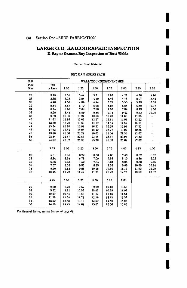
I
6 6 Section One-SHOP FABRICATION
LARGE O.D. RADIOGRAPHIC INSPECTION X-Ray or Gamma Ray Inspection of Butt Welds
Carbon Steel Material
NET MAN HOURS EACH
I / /
O . D .
Pipe Size
26 28 30 32 34 36 38 40 42 44 46 48 54 60
26 28 30 32 34 36
26 28 30 32 34 36
WALL THICKNESS IN INCHES .750
or Less 1.00 1.25 1.50 1.75 2.00 2.25
3.15 3.31 3.44 3.71 3.97 4.27 4.56 3.65 3.78 3.94 4.19 4.46 4.75 5.07 4.40 4.56 4.69 4.94 5.23 5.50 5.79 5.44 5.57 5.70 5.98 6.27 6.54 6.80 6.74 6.90 7.02 7.30 7.57 7.84 8.13 8.29 8.45 8.59 8.86 9.14 9.42 9.73 9.89 10.06 10.24 10.50 10.78 11.06 11.38
11.62 11.86 12.03 12.27 12.61 12.91 13.22 13.50 13.70 13.89 14.19 14.54 14.82 15.14 15.54 15.70 15.92 16.22 16.59 16.91 17.22 17.63 17.84 18.08 18.40 18.77 19.07 19.36 19.86 20.06 20.29 20.61 21.04 21.30 21.62
I 22.34 22.57 22.83 23.18 23.67 23.96 24.32 24.82 25.07 25.36 25.76 26.30 26.62 27.02
2.50
4.90 5.42 6.18 7.17 8.50
10.05 o o
o o
o ~
o o
~ 1 7 6
~
N
~ 1 7 6
2.75 3.00 3.25 3.50 3.75 4.00 4.25 4.50
5.31 5.81 6.22 6.56 7.06 7.49 8.32 8.70 5.84 6.54 6.78 7.09 7.58 8.10 8.86 9.22 6.56 7.33 7.52 7.84 8.34 8.86 9.58 9.95 7.57 8.32 8.51 8.83 9.33 9.86 10.59 10.94 8.90 9.63 9.86 10.16 10.66 11.17 11.92 12.29
10.48 11.22 11.42 11.73 12.22 12.75 13.50 13.87
4.75 5.00 5.25 5.50 5.75 6.00
9.00 9.26 9.52 9.92 10.18 10.56 9.52 9.81 10.05 10.43 10.69 11.09
10.29 10.54 10.80 11.17 11.46 11.84 11.28 11.54 11.79 12.16 13.15 13.57 12.59 12.88 13.10 13.50 14.50 15.26 14.18 14.45 14.69 15.07 16.06 15.85
For General Notes, see the bottom of page 61,.
I I I I I
I
I
I
I
I
I
I
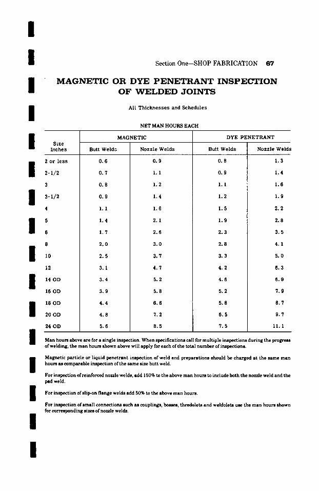
I t
o
/
Section 0ne-SHOP FABRICATION 87
M A G N E T I C O R D Y E P E N E T R A N T I N S P E C T I O N
O F W E L D E D J O I N T S
All Thicknesses and Schedules
NET MAN HOURS EACH
/
t I
Size Inches
2 or less
2-1/2
3-1/2
I 5
6
8
12
I 14 OD
16 OD
18 OD
20 OD
24 OD
Butt Welds
0.6
0.7
0.8
0.9
1.1
1.4
1.7
2.0
2.5
3.1
3.4
3.9
4.4
4.8 5.6
MAGNETIC
Nozzle Welds
0.9
1.1
1.2
1.4
1.6
2.1
2.6
3 .0
3.7
4 .7
5.2
5.8
6.6
7.2
DYE PENETRANT
Butt Welds
0.8
0.9
1.1
1.2
1.5
1.9
2.3
2.8
3.3
4 .2
4.6
5.2
5.8
6.5
8 .5 7 .5
Nozzle Welds
1.3
1.4
1.6
1.9
2.2
2.8
3.5
4.1
5.0
6 .3
6.9
7.9
8 .7
9.7
/ 11.1
Man hours above are for a single inspection. When specifications call for multiple inspections during the progress of welding, the man hours shown above will apply for each of the total number of inspections.
Magnetic particle or liquid penetrant inspection of weld end preparations should be charged at the same man hours as comparable inspection of the same size butt weld.
For inspection of reinforced nozzle welds, add 150% to the above man hours to include both the nozzle weld and the pad weld.
For inspection of slip-on flange welds add 50% to the above hours. man
For inspection of small connections such as couplings, bosses, thredolets and weldolets use the man hours shown for corresponding sizes of nozzle welds.
I l
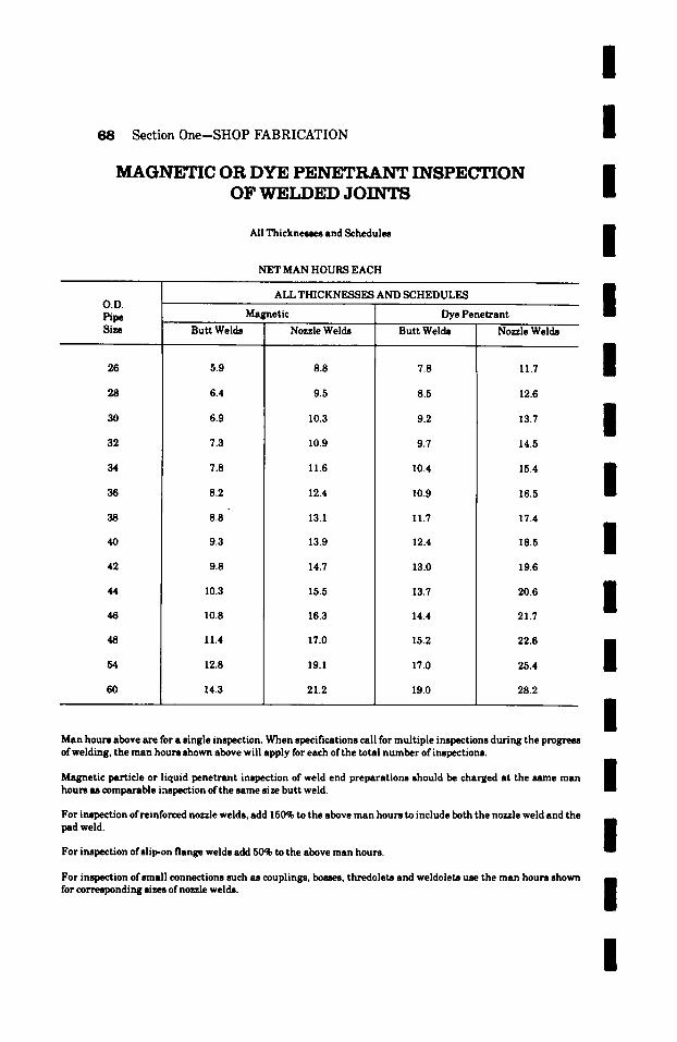
Section 0ne-SHOP FABRICATION
MAGNETIC OR DYE P E N E T R A N T INSPECTION OF WELDED JOINTS
All Thicknesses and Schedules
NET MAN HOURS EACH
ALL THICKNESSES AND SCHEDULES
Magnetic ] Dye Penetrant
/
/
I /
O.V. Pipe Size
26
28
30
32
34
36
38
40
42
44
46
48
54
60
Butt Welds
5.9
6.4
6.9
7.3
7.8
8.2
8.8
9.3
9.8
10.3
10.8
11.4
12.8
Nozzle Welds
8.8
9.5
10.3
10.9
11.6
12.4
13.1
13.9
14.7
15.5
16.3
17.0
19.1
14.3 21.2
Butt Welds
7.8
8.5
9.2
9.7
10.4
10.9
11.7
12.4
13.0
13.7
14.4
15.2
17.0
19.0
Nozzle Welds
11.7
12.6
13.7
14.5
/
/
/ 15.4 /
16.5
17.4
18.5
19.6
20.6
21.7
22.6
25.4
28.2
/
I /
I Man hours above are for a single i ~ t i o n . When specifications call for multiple inspections during the progress of welding, the man hours shown above will apply for each of the total number of inspections. ~m
Magnetic particle or liquid penetrant inspection of weld end preparations should be charged at the same man / hours as comparable i,-mpection of the same size butt weld. B
For i ~ i o n ofreinforeed nozzle welds, add 150% to the above man hours to include both the nozzle weld and the
pad weld. i
For inspection of slip-on flange welds add 50% to the above man hours.
For inspection of small connections such u couplings, bosses, thredolets and weldolets use the man hours shown for corresponding sizes of nozzle welds. I
/
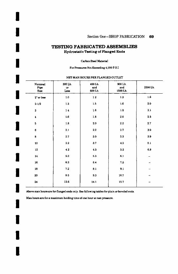
I I I I I
Section One-SHOP FABRICATION 64}
TESTING FABRICATED ASSEMBLIES H y d r o s t a t i c T e s t i n g o f F l a n g e d E n d s
Carbon Steel Material
For Pressures Not Exceeding 4,000 P.S.I.
NET MAN HOURS PER FLANGED OUTLET
/
I / /
I / /
Nominal Pipe Size
2 ~ or less
2-1/2
10
14
16
18
20
24
300 Lb. or
Less
1.0
1.3
1.4
1.6
1.8
2.1
2.7
3.2
4.2
5.0
6.3
7.2
8.5
12.6
400 Lb. and
600 Lb.
1.2
1.5
1.6
1.8
2.0
2.2
3.0
3.7
4.5
5.3
6.4
8.1
9.3
14.1
900 Lb. and
1500 Lb.
1.3
1.6
1.8
2.0
2.2
2.7
3.3
4.2
5.2
6.1
7.5
9.1
10.7
15.7
Above man hours are for flanged ends only. See following tables for plain or beveled ends.
2500 Lb.
1.6
2.0
2.1
2.5
2.7
3.0
3.9
5.1
6.8
/
I /
Man hours are for a maximum holding time ofone hour at test pressure.
I
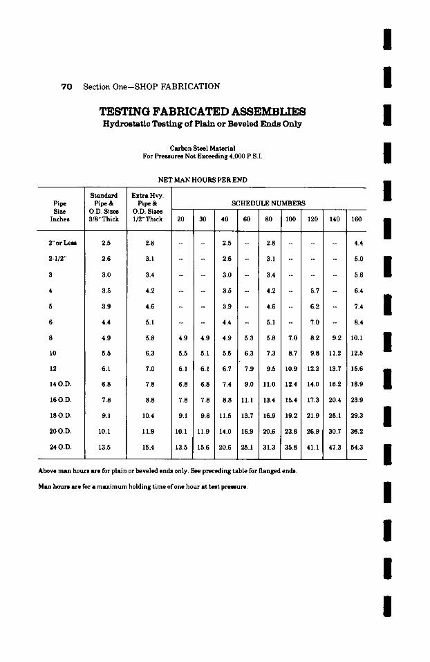
7 0 S e c t i o n O n e - - S H O P F A B R I C A T I O N
TESTING FABRICATED ASSEMBLIES H y d r o s t a t i c T e s t i n g o f P l a i n o r B e v e l e d E n d s O n l y
Carbon Steel Material For Pressures Not Exceeding 4,000 P.S.I.
NET MAN HOURS PER END
Pipe Size
Inches
2" or Less
2- I /2"
10
12
14 O . D .
16 O.D.
18 O . D .
2 0 0 . D .
24 O.D.
S t a n d a r d
Pipe & O.D. Sizes 3/8" Thick
2.5
2.6
3.0
3.5
3.9
4 . 4
4 . 9
5.5
6.1
6 . 8
7.8
9 .1
10.1
13.5
E x t r a Hvy. P i p e &
O.D. Sizes I / 2 " T h i c k
S C H E D U L E N U M B E R S
20 30 40 60 80 100 120 140 160
2.8 . . . . 2.5 -- 2.8 . . . . . . 4.4
3.1 . . . . 2.6 -- 3.1 --
3.4 - -- 3.0 -- 3.4 --
5.0
5.6
4.2 -- - 3.5 -- 4.2 -- 5.7 -- 6.4
4 . 6 . . . . 3 . 9 - 4 . 6 -- 6 . 2 -- 7 . 4
5.1 . . . . 4.4 -- 5.1 - 7.0 -- 8.4
5.8 4.9 4.9 4.9 5.3 5 . 8 7.0 8.2 9.2 10.1
6.3 5.5 5.1 5.5 6.3 7.3 8.7 9.8 11.2 12.5
7.0 6.1 6.1 6.7 7.9 9.5 10.9 12.2 13.7 15.6
7.8 6.8 6.8 7.4 9.0 11.0 12.4 14.0 16.2 18.9
8.8 7.8 7.8 8.8 11.1 13.4 115 .4 17.3 20.4 23.9
10.4 9.1 9.8 11.5 13.7 16.9 19.2 21.9 25.1 29.3
11.9 10.1 11.9 14.0 16.9 20.6 23.8 26.9 30.7 36.2
15.4 13.5 15.6 20.6 25.1 31.3 35.8 41.1 47.3 54.3
Above m a n hours a re for p la in or beveled ends only. See preced ing tab le for f langed ends.
Man hours a re for a m a x i m u m hold ing t ime of one hour a t t es t p ressure .
/
I / / / /
I /
I I /
/ /
/ / /

I /
I / / / / /
I / / / / /
I
Section One-SHOP FABRICATION 71
HEAVY WALL TESTING FABRICATED ASSEMBLIES H y d r o s t a t i c T e s t i n g o f P l a i n o r B e v e l e d E n d s O n l y
Carbon Steel Material
For Pressures Not Exceeding 4,000 P.S.I.
NET MAN HOURS PER END
Nominal t~pe Size
WALL THICKNESS IN INCHES
.750 1.00 1.25 1.50 1.75 2.00 2.25 2.50
3" or less 6.3 6.9 . . . . . . . . . . 4 7.2 7.5 7.9 8.5 . . . . . . . 5 -- 8.2 8.7 9.2 10.5 12.9 . . . . 6 - 9.5 10.3 10.8 13.9 16.3 19.0 - 8 - 11.5 12.1 13.6 17.3 20.1 23.7 28.6 10 . . . . 13.5 16.9 21.0 24.3 28.5 33.5 12 . . . . . . 20.5 24.3 28.6 33.9 39.2 14 . . . . . . 23.4 27.7 32.5 38.1 45.0 16 . . . . . . . 31.1 37.2 43.4 51.9 18 . . . . . . . . . . 41.5 48.4 57.2 20 . . . . . . . . 48.4 57.2 69.2 22 . . . . . . . . . . . . 75.6 24 . . . . . . . . . . . . . 82.2
2.75 3.00 3.25 3.50 3.75 4.00 4.25 4.50
10 38.3 44.0 . . . . . . . . . . . 12 44.8 51.3 57.8 66.0 . . . . . . 14 51.1 58.0 65.7 74.4 84.8 95.2 - -- 16 58.8 67.5 76.2 86.5 98.7 112.5 . . . . 18 65.7 76.2 86.5 99.3 113.3 129.7 -- -- 20 78.8 88.3 101.2 114.2 129.7 147.1 166.8 180.9 22 86.0 96.9 110.3 124.6 141.7 161.0 182.5 202.0 24 93.5 103.4 119.5 135.1 154.0 174.9 198.3 218.7
4.75 5.00 5.25 5.50 5.75 6.00
20 198.3 212.4 226.6 236.0 262.7 280.1 22 214.0 229.7 251.4 264.0 289.2 308.3 24 233.5 251.4 274.7 287.9 311.5 333.2
Above man hours are for plain or beveled ends only. See preceeding table for flanged ends.
Man hours are for a maximum holding t ime of one hour at test pressure.
!
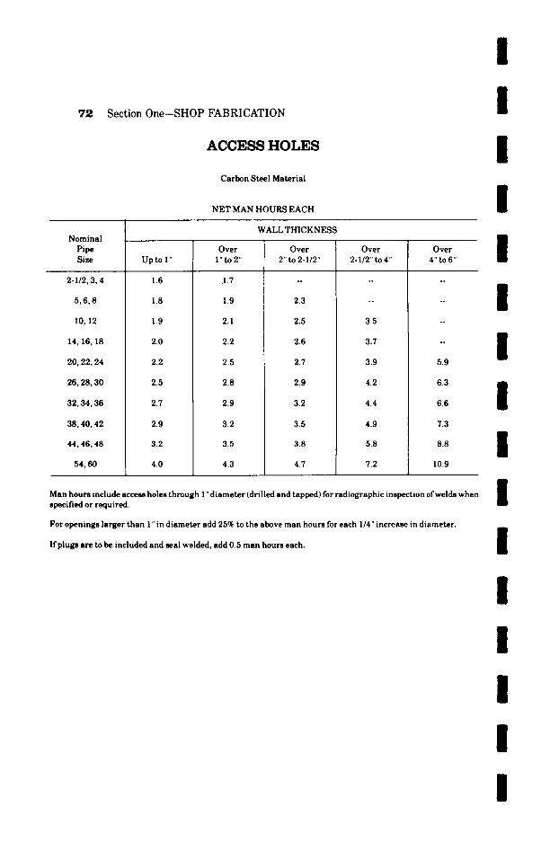
72 Section One-SHOP FABRICATION
ACCESS HOLES
Carbon Steel Material
NET MAN HOURS EACH
I /
I /
Nominal Pipe Size
2-1/2, 3, 4
5,6,8
10,12
14, 16, 18
20,22,24
26,28,30
32, 34, 36
38, 40, 42
44, 46, 48
54, 60
WALL THICKNESS
Upto I"
1.6
1.8
1.9
2.0
2.2
2.5
2.7
2.9
3.2
4.0
Over l" to 2"
.I .7
1.9
2.1
2.2
2.5
2.8
2.9
3.2
3.5
4.3
Over 2"to 2-I/2"
2.3
2.5
2.6
2.7
2.9
3.2
3.5
3.8
4.7
Over 2-1/2" to 4"
3.5
3.7
3.9
4.2
4.4
4.9
5.8
7.2
Over 4"to 6"
5.9
6.3
6.6
7.3
8.8
10.9
I I I / /
Man hours include access holes through 1 "diameter (drilled and tapped) for radiographic inspection of welds when specified or required.
For openings larger than 1" in diameter add 25% to the above man hours for each 1/4" increase in diameter.
If plugs are to be included and seal welded, add 0.5 man hours each.
/ / / / /
I /
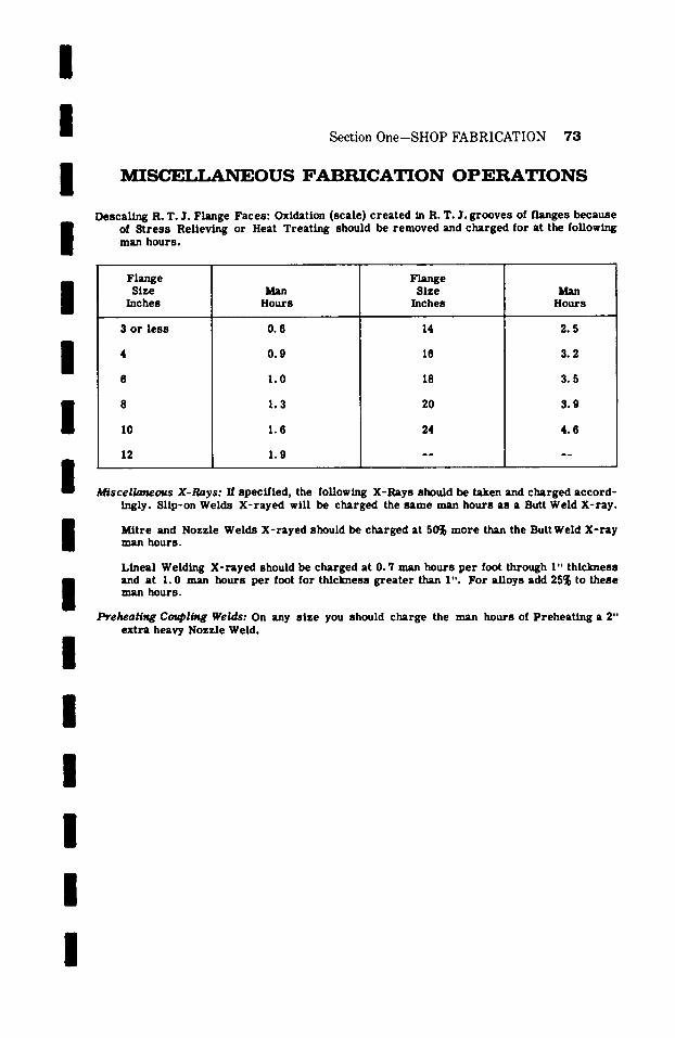
I I I I
Section One-SHOP FABRICATION 73
M I S C E I J _ , A N E O U S F A B R I C A T I O N O P E R A T I O N S
D e s c a l i ~ R. T. J'. Flange Faces : Oxidation (scale) c rea ted in R. T. ~. grooves of f langes because of S t r e s s Relieving or Heat Treat ing should be removed and charged for at the following man hours .
I /
I I
F ~ e Size
Inches
3 or l e s s
I0
12
Man Hours
0.6
0 .9
1.0
1.3
1.6
1 .9
FLz.ge Size
Inches
14
16
18
20
24
Man Hours
2.5
3.2
3.5
3.9
4 .6
Miscella~ous X-Rays: If specif ied, the following X-Rays should be taken and charged acco rd -
I I I I I I I
Ingly. Sllp-on Welds X- r ayed will be charged the same man hours as a Butt Weld X- ray .
Mitre and Nozzle Welds X - n y e d should be charged at 50~ more than the Butt Weld X - r a y man hours.
Lineal Welding X- r ayed should be charged at 0. " /man hours pe r foot through I" th ickness and at I. 0 man hours per foot for thickness g r ea t e r than I" . For al loys add 25~ to these man hours.
Preheafl,g Co$~bli~g Welds: On any s ize you should charge the man hours of Prehea t ing a 2" ext ra heavy Nozzle Weld.
I
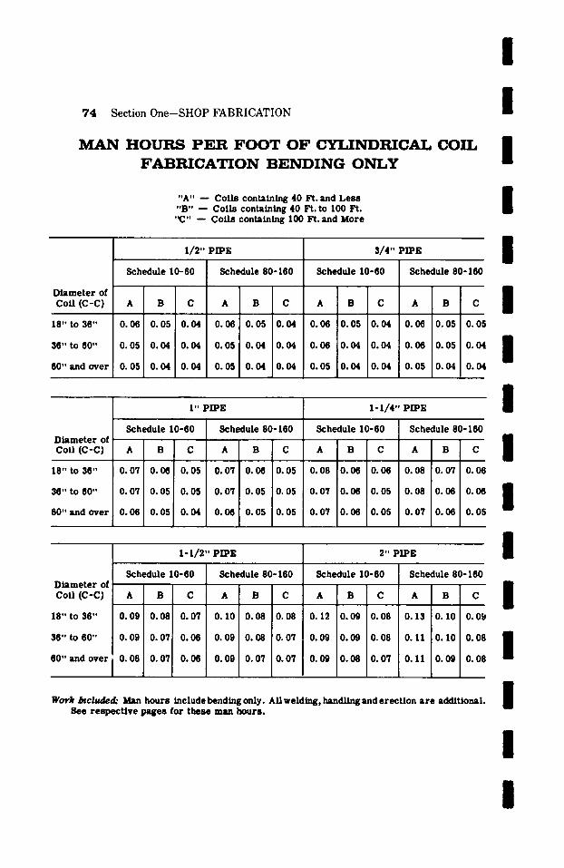
7 4 Sec t ion O n e - S H O P F A B R I C A T I O N
M A N H O U R S P E R F O O T O F C Y L I N D I ~ C ~ - ] ' , C O I L F A B R I C A T I O N B E N D I N G O N L Y
"A" - - Coils containing 40 Ft. and Less "B" - - Coils containing 40 Ft. to I00 Ft.
" C " - - Coils containing I00 Ft. and More
Diamete r of CoU (C-C)
18" to 36"
36" to 60"
60" and over
1/~.,, pipe
Schedule 10-60
A B C
0.06 0.05 0.04
0.05 0.04 0.04
0.05 0.04 0.04
Schedule 80-160
A B C
0.08 0.05 0.04
0.05 0.04 0.04
0.05 0.04 0.04
s/4,, Pil,~:
Schedule 10.60
A B C
0.08 0.05 0.04
0.06 0.04 0.04
0.05 0.04 0.04
/ /
I I
. /
I" PIPE
Schedule 80-160
A B C
0.06 0.05 0.0!
0.08 0.05 0.04
0.05 0.04 0.0~
1-1/4,, P~E
/ / /
Diamete r of cou (c-c)
18" to 36"
36" to 60"
60" and over
Schedule 10-60
A B C
0.07 0.06 0.05
0.07 0.05 0.05
0.08 0.05 0.04
Schedule 80.160
0. 07
0 .07
0.06
B C
0.06 0.05
0.05 0. 05
O. 05 O. 05
Schedule 10-60
A B C
0.08 0.06 0.06
0.07 0.06 0.05
0.07 0.06 0.05
Schedule 80-160
A B C
0.08 0.07 0.06
0.08 0.08 0.06
0.07 0.06 0.05
1 - I / 2 " PIPE 2" PIPE
Schedule 10.80 Schedule 80-160 Schedule 10-60 Schedule 80-160
I I /
Diamete r of Coll (C-C)
18" to 36"
36" to 60"
60" and over
A B C
0.09 0.08 0.07
0.09 0.07 0.06
0.08 0.07 0.06
A B
0 .10 0.08 0.08
0.09 0.08 0.07
0.09 0.07 0.07
~, B C
O. 12 0 .09 0.08
0.09 0.09 0.08
0.09 0.08 0.07
A B C
0.13 0. I0 0.09 I
0.11 0. I0 0.08 I
a 0. I I 0.09 0.08
W o r h / n c ~ d . " Man hours include bending only. All welding, handling and erec t ion a r e additional. See r e spec t ive pages for these man hours . I
I I
I n i i i I I I i I i n i I m I
S e c t i o n T w O
F I E L D
F A B R I C A T I O N A N D E R E C T I O N
This section is intended to suffice for the com- plete labor involved in the installat ion and field fabrication as may be necessa ry to put a sys tem of p roces s piping into operat ion in an industr ial or chemical plant.
The man hours l isted are for labor only and do not have any bearing on mate r i a l s or equipment.
All labor for unloading from ra i l road ca r s or t rucks hauling to and unloading at s torage facil- i t ies, hauling from s torage to erect ion site and rigging or hoisting into place have been given due considerat ion in the man hours l isted for the var ious operat ions. While it is t rue that the aforementioned operat ions involve more t ime than is required mere ly to haul ma te r i a l s from and on the job, fabricating shop or s torage area , never the less , we have found that these are op- erat ions that will balance themselves out over a complete piping job. No considerat ion has been given to overhead or profit .
For the field fabrication and erect ion of alloy and non- fe r rous piping and fittings, apply the percentages which appear under Section Three to the following pages l ist ing the var ious field operat ions.
75
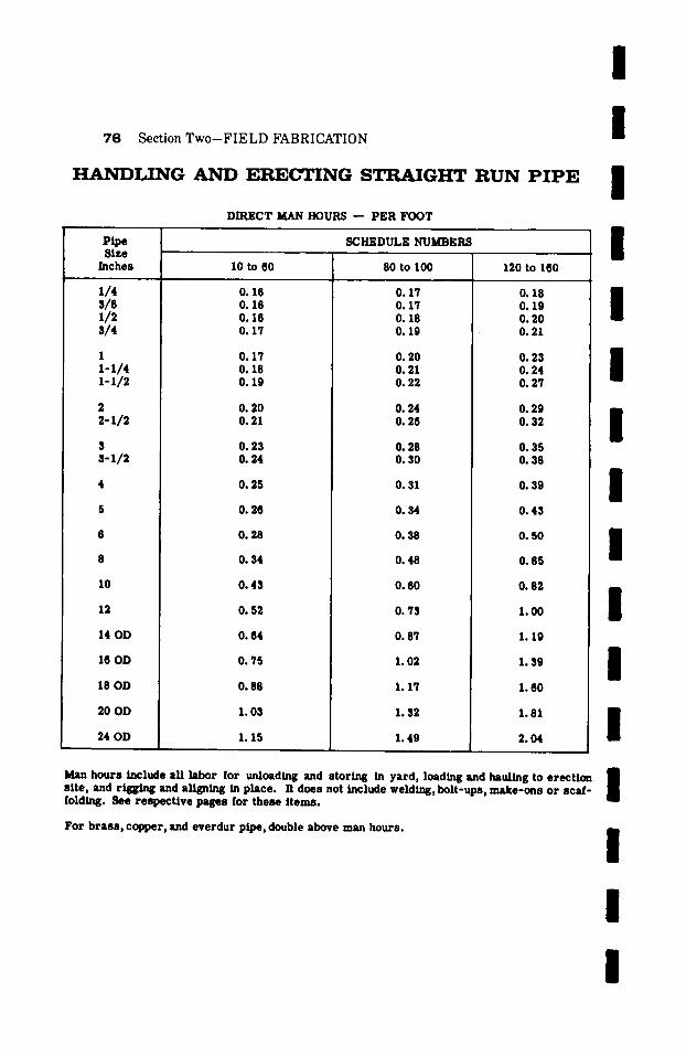
7 6 Section T w o - F I E L D F A B R I C A T I O N
H A N D L I N G A N D E R E C T I N G S T R A I G H T R U N P I P E
DIRECT MAN HOURS -- PER FOOT
Pipe Size
Inches I0 to 60
1/4 O. 16 3/8 0.16 x/2 O.le 3/4 O. 17
1 0.17 1-1/4 o.18 1-1/2 o.19
2 0. 20 2-1/2 o.21
3 0.23 3-x/2 o. 24
4 0.25
5 O. 28
0. 28
0.34
10 0.43
12 0.52
14 OD O. 64
18 OD O. 75
18 OD O. 88
20 OD 1.03
24 OD 1.15
SCHEDULE NUMBERS
80 to 100
0.17 0.17 0.18 0.19
O. 20 0.21 0.22
0.24 O. 26
O. 28 O. 30
0.31
0.34
O. 38
O. 48
0. 80
0.73
0.87
I. 02
1.17
1.32
1.49
120 to 160
0.18 0.19 0.20 0.21
0.23 0.24 O. 27
0. 29 0.32
0.35 0. 38
0.39
0.43
0. 50
0.65
0.82
1.00
1.19
1.39
1.60
1.81
2.04
I I I I I I I I I I I I
Man hours include all labor for unloading and storing in yard, loading and hauling to erection site, and rigging and aligning in place. It does not include welding, bolt-ups, make-ons or scal-
E folding. See respecUve pages for these items.
For brass , copper, and everdur pipe, double above man hours.
I I I

/
I / /
Section Two-FIELD FABRICATION 77
H A N D L I N G A N D ERECTING H E A V Y WALL STRAIGHT R U N PIPE
Carbon Steel Material
NET MAN HOURS PER FOOT
Nominal WALL THICKNESS IN INCHES Pipe Size .750 1.00 1.25 1.50 1.75 2.00 2.25 2.50
I 3" or less 0.36 0.43 . . . . . . . . . . . 4 0.40 0.48 0.56 0.65 . . . . . . . . 5 -- 0.54 0.65 0.76 0.87 0.98 . . . . 6 -- 0.60 0.71 0.81 1.09 1.19 1.30 -- 8 -- 0.71 0.80 0.95 1.10 1.25 1.40 1.57
I 10 . . . . 0.95 1.00 1.18 1.36 1.54 1.72 12 . . . . . . 1.17 1.34 1.51 1.69 1.86 14 . . . . . . 1.35 1.50 1.66 1.81 1.97 16 . . . . . . . 1.56 1.73 1.89 2.07 18 . . . . . . . . . . 1.78 1.96 2.15
I 20 . . . . . . . . . . 1.80 1.98 2.22 22 . . . . . . . . . . . . . . 2.28 24 . . . . . . . . . . . . . . 2.33
I / /
I /
I /
2.75 3.00 3.25 3.50
10 1.98 2.24 . . . . 12 2.14 2.42 2.73 3.09 14 2.26 2.56 2.89 3.27 16 2.38 2.69 3.04 3.43 18 2.47 2.79 3.16 3.57 20 2.55 2.89 3.27 3.69 22 2.62 2.96 3.34 3.78 24 2.71 3.06 3.46 3.91
4.75 5.00 5.25 5.50
20 6.16 6.71 7.25 7.55 22 6.31 6.88 7.43 8.02 24 6.52 7.10 7.67 8.29
3.75
~
3.67 3.84 3.99 4.13 4.23 4.37
5.75
8.38 8.58 8.87
4.00 4.25 4.50
4.07 . . . . 4.26 . . . . 4.43 . . . . 4.59 5.09 5.60 4.70 5.21 5.73 4.86 5.39 5.92
. .
6.00
8.97 9.18 9.49
Man hours include all labor for unloading and storing in yard, loading and haul ing to erection site, and rigging and aligning in place.
Man hours do not include welding, bolt-ups, make-ons or scaffolding. See respective tables for these items.
/
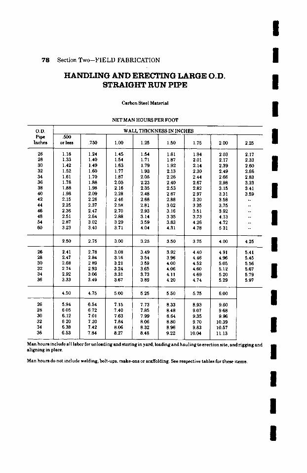
7 8 Section Two--FIELD FABRICATION
H A N D L I N G A N D ERECTING LARGE O.D. STRAIGHT R U N PIPE
Carbon Steel Material
NET MAN HOURS PER FOOT
/ /
I /
O.D. Pipe .500
Inches or less
WALL THICKN~ IN INCHES
�9 750 1.00 1.25 1.50 [ 1.75 2.00 2.25 I 26 1.18 1.24 1.45 1.54 1.61 1.94 2.03 2.17 28 1.33 1.40 1.54 1.71 1.87 2.01 2.17 2.33 m 30 1.42 m 1.49 1.63 1.79 1.92 2.14 2.39 2.60 l 32 1.52 1.60 1.77 1.93 2.13 2.30 2.49 2.66 34 1.61 1.70 1.87 2.05 2.26 2.44 2.66 2.83 36 1.78 1.88 2.05 2.23 2.40 2.67 2.98 3.23 m m
38 1.88 1.98 2.16 2.35 2.53 2.82 3.15 3.41 m 40 1.98 2.09 2.28 2.48 2.67 2.97 3.31 3.59 | 42 2.15 2.26 2.46 2.68 2.88 3.20 3.58 -- 44 2.25 2.37 2.58 2.81 3.02 3.35 3.75 46 2.36 2.47 2.70 2.93 3.16 3.51 3.92 m 48 2.51 2.64 2.88 3.14 3.35 i 3.73 4.13 ! 54 2.87 3.02 3.29 3.59 3.83 4.26 4.72 60 3.23 3.40 3.71 : 4.04 4.31 4.78 5.31
2.50 2.75 3.00 3.25 3.50 3.75 4.00 4.25
26 2.41 2.78 3.08 3.49 3.92 4.40 4.91 5.41 28 2.47 2.84 3.16 3.54 3.96 4.46 4.96 5.45 30 2.68 2.89 3.21 3.59 4.00 4.52 5.05 5.56 32 2.74 2.93 3.24 3.65 4.06 4.60 5.12 ) 5.67 34 2.92 3.06 3.31 3.73 4.11 4.69 5.20 I 5.79 36 3.33 3.49 3.67 3.89 4.20 4.74 5.29 5.97
4.50 4.75 5.00 5.25 5.50 5.75 6.00
26 5.94 6.54 7.15 7.73 8.33 8.93 9.60 28 6.05 6.72 7.40 7.85 8.48 9.07 9.68 30 6.12 7.01 7.63 7.99 8.64 9.35 9.96 32 6.20 7.20 7.84 8.06 8.80 9.70 10.39 34 6.38 7.42 8.06 8.32 8.96 9.83 10.57 36 6.53 7.84 8.27 8.48 9.22 10.04 11.13
Man hours include all labor for unloading and storing in yard, loading and hauling to erection site, and rigging and aligning in place.
Man hours do not include welding, bolt-ups, make-ons or scaffolding. See respective tables for these items.
I / /
I / /
I /
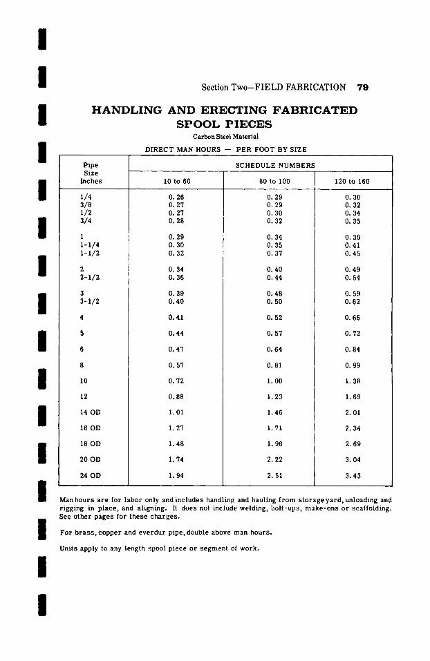
I I I /
Section Two-FIELD FABRICATION 79
H A N D L I N G A N D E R E C T I N G F A B R I C A T E D
S P O O L P I E C E S Carbon Steel Material
DIRECT MAN HOURS - - PER FOOT BY SIZE
I I I I I I I I I
Pipe Size
Inches
1/4 3/8 1/2 3/4
1 1-1/4 1-1/2
2 2-1/2
3 3-1/2
I0
12
14 OD
16 OD
18 OD
20 OD
24 OD
SCHEDULE NUMBERS
10 to 60
0.26 0.27 0.27 O. 28
0 .29 0 .30 0.32
0.34 0 .36
0 .39 0 .40
0.41
0 .44
0.47
0.57
80 to 100
0 .29 0 .29 0 .30 0.32
0.34 0 .35 0 .37
O. 40 O. 44
O. 48 O. 50
0 .52
0 .57
O. 64
O. 72
0.88
1.01
1.27
1.48
1.74
1.94
0.81
1. O0
1.23
1.46
1.71
1.96
2.22
2.51
120 to 160
0 .30 0 .32 0.34 0 .35
0 .39 0.41 0 .45
0 .49 0. 54
0 .59 0 .62
0 .66
0 .72
0.84
0 .99
1.38
1.69
2.01
2.34
2.69
3.04
3.43
Man hours a r e for labor only and includes handling and hauling f rom s to r age yard , unloading and
/
I
r igging in p lace , and aligning. It does not include welding, bo l t -ups , make -ons or scaffolding. See o ther pages for these cha rges .
For b r a s s , copper and eve rdu r pipe, double above man hours .
Units apply to any length spool p iece or segment of work.
/
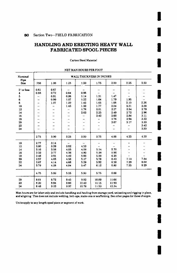
80 Section Two-FIELD FABRICATION
H A N D L I N G A N D E R E C T I N G H E A V Y W A L L F A B R I C A T E D S P O O L P I E C E S
Carbon Steel Material
NET MAN HOURS PER FOOT
I I I I
WALL THICKNESS IN INCHES Nominal Pipe Size .750 1.00 1.25 1.50 1.75 2.00 2.25
3" or less 0.61 0.67 . . . . . . . . . . 4 0.68 0.72 0.84 0.98 . . . . . . 5 -- 0.81 0.98 I. 14 1.31 1.47 -- 6 -- 0.90 1.07 1.22 1.64 1.79 1.95 8 -- 1.07 1.20 1.43 1.65 1.88 2.10 10 . . . . 1.43 1.50 1.77 2.04 2.31 12 . . . . . . 1.76 2.01 2.27 2.54 14 . . . . . . 2.03 2.25 2.49 2.72 16 . . . . . . . . 2.42 2.60 2.84 18 . . . . . . . . . . . 2.76 2.94 20 . . . . . . . . . . 3.07 3.17 22 . . . . . . . . . . . . . . 24 . . . . . . . . . . . . . .
2.75 3.00 3.25 3.50 3.75 4.00 4.25
10 2.77 3.14 . . . . . . . . . . 12 3.00 3.39 3.82 4.33 . . . . . . 14 3.16 3.58 4.05 4.58 5.14 5.70 -- 16 3.33 3.77 4.26 4.80 5.38 5.96 -- 18 3.46 3.91 4.42 5.00 5.59 6.20 -- 20 3.57 4.05 4.58 5.17 5.78 6.43 7.13 22 3.67 4.14 4.68 5.29 5.92 6.58 7.29 24 3.79 4.28 4.84 5.47 6.12 6.80 7.55
2.50
~ 1 7 6
~ 1 7 6
~ 1 7 6
~ 1 7 6
2.36 2.58 2.79 2.96 3.11 3.23 3.33 3.42 3.50
4.50
~ 1 7 6
~ 1 7 6
~ 1 7 6
~ 1 7 6
o ~
7.84 8.02 8.29
4.75 5.00 5.25 5.50 5.75 6.00
20 8.01 8.72 9.43 9.82 10.89 11.66 22 8.20 8.94 9.66 10.43 1 I. 15 11.93 24 8.48 9.23 9.97 10.78 11.53 12.34
Man hours are for labor only and include handling and hauling from storage yard, unloading and rigging in place, and aligning. This does not include welding, bolt-ups, make-ons or scaffolding. See other pages for these charges.
Units apply to any length spool piece or segment of work.
/ / / / I I I I I I I I
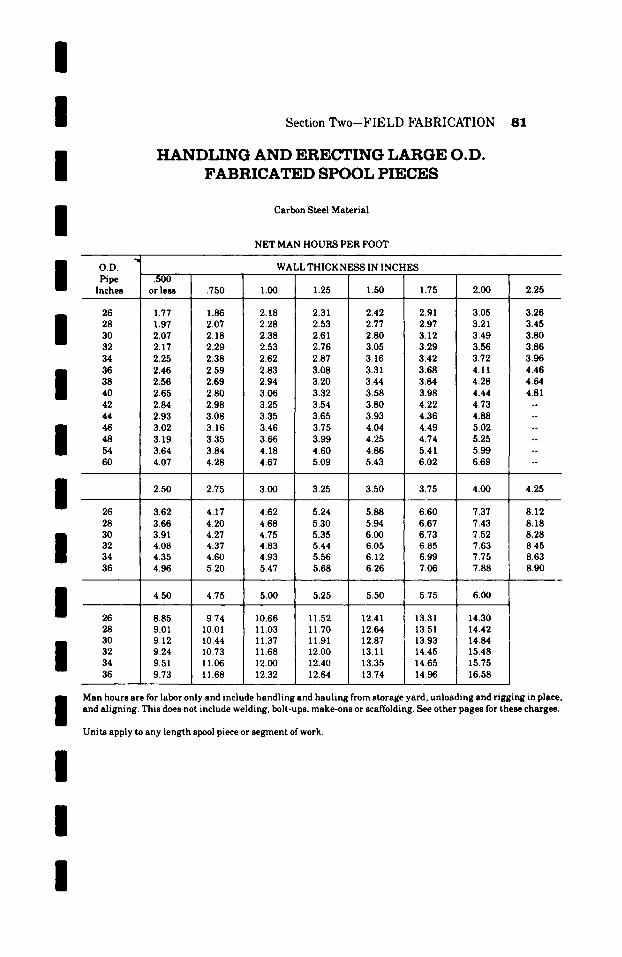
/
I I /
Section Two-FIELD FABRICATION 81
H A N D L I N G A N D ERECTING LARGE O.D. FABRICATED SPOOL PIECES
Carbon Steel Material
NET MAN HOURS PER FOOT
I O.D. WALL THICKNESS IN INCHES Pipe .5OO 1
Inches or less .750 1.00 1.25 1.50 1.75 2.00 2.25
26 1.77 1.86 2.18 2.31 2.42 2.91 3.05 3.26 28 1.97 2.07 2.28 2.53 2.77 2.97 3.21 3.45 30 2.07 2.18 2.38 2.61 2.80 3.12 3.49 3.80 32 2.17 2.29 2.53 2.76 3.05 3.29 3.56 3.86 34 2.25 2.38 2.62 2.87 3.16 3.42 3.72 3.96 36 2.46 2.59 2.83 3.08 3.31 3.68 4.11 4.46 38 2.56 2.69 2.94 3.20 3.44 3.84 4.28 4.64 40 2.65 2.80 3.06 3.32 3.58 3.98 4.44 4.81 42 2.84 2.98 3.25 3.54 3.80 4.22 4.73 -- 44 2.93 3.08 3.35 3.65 3.93 4.36 4.88 -- 46 3.02 3.16 3.46 3.75 4.04 4.49 5.02 -- 48 i 3.19 3.35 3.66 3.99 4.25 4.74 5.25 -- 54 i 3.64 3.84 4.18 4.60 4.86 5.41 5.99 -- 60 4.07 4.28 4.67 5.09 5.43 6.02 6.69 --
I I I I I I /
2.50 2.75 3.00 3.25 3.50 3.75 4.00 4.25
26 3.62 4.17 4.62 5.24 5.88 6.60 7.37 8.12 28 3.66 4.20 4.68 5.30 5.94 6.67 7.43 8.18 30 3.91 4.27 4.75 5.35 6.00 6.73 7.52 8.28 32 4.08 4.37 4.83 5.44 6.05 6.85 7.63 8.45 34 4.35 4.60 4.93 5.56 6.12 6.99 7.75 8.63 36 4.96 5.20 5.47 5.68 6.26 7.06 7.88 8.90
4.50 4.75 5.00 5.25 5.50 5.75 6.00
26 8.85 9.74 10.66 11.52 12.41 13.31 14.30 28 9.01 10.01 11.03 11.70 12.64 13.51 14.42 30 9.12 10.44 11.37 I 1.91 12.87 13.93 14.84 32 9.24 10.73 I 1.68 12.00 13. I I 14.45 15.48 34 9.51 11.06 12.00 12.40 13.35 14.65 15.75 36 9.73 I 1.68 12.32 I 12.64 13.74 14.96 16.58
Man hours are for labor only and include handling and hauling from storage yard, unloading and rigging in place, and aligning. This does not include welding, bolt-ups, make-ons or scaffolding. See other pages for these charges.
Units apply to any length spool piece or segment of work.
I
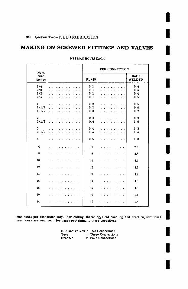
8@, Section T w o - - F I E L D FABRICATION
M A K I N G O N S C R E W E D F I T T I N G S A N D V A L V E S
NET MAN HOURS EACH
PER CONNECTION Nora. S i z e
I n c h e s
1 / 4 . . . . . . . . . .
3 / 8 . . . . . . . . . .
1/2 . . . . . . . . . . 3 / 4 ..........
I . . . . . . . . . .
1-1/4 . . . . . . . . . .
1-1/2 . . . . . . . . . .
2 . . . . . . . . . .
2 - I / 2 . . . . . . . . . .
3 . . . . . . . . . .
3 - I / 2 . . . . . . . . . .
20
24
PLAIN
0 . 1 . . . . . . . .
0 . I . . . . . . . .
0 . 1 . . . . . . . .
0 . I . . . . . . . .
0 . 2 . . . . . . . .
0 . 2 . . . . . . . .
0 . 3 . . . . . . . .
0 . 3 . . . . . . . .
0 . 4 . . . . . . . .
0 . 4 . . . . . . . .
0 . 4 . . . . . . . .
0 . 5 . . . . . . . .
. 7 �9 �9 �9
.9 �9 �9 �9
1 .1 . . . . . .
1 . 2 . . . . . .
1 . 3
1 . 4
l . S
1 . 6
1 . 7
B A C K
W E L D E D
0.4 0.4 0.4 0.5
0 . 5
0 . 6
0 . 7
0.9 1 . 0
1 . 2
1 . 4
1.6
2 . 3
2 . 8
3 . 4
3 . 9
4 . 2
4 . 5
4 . 8
5 . 1
5 . 5
I I I I I I I I I I I I
M a n h o u r s p e r c o n n e c t i o n o n l y . F o r c u t t i n g , t h r e a d i n g , f i e l d h a n d l i n g a n d e r e c t i o n , a d d i t i o n a l
m a n h o u r s a r e r e q u i r e d . See p a g e s p e r t a i n i n g t o t h e s e o p e r a t i o n s .
E l l s a n d V a l v e s = T w o C o n n e c t i o n s
T e e s = T h r e e C o n n e c t i o n s
C r o s s e s = F o u r C o n n e c t i o n s
I I I I
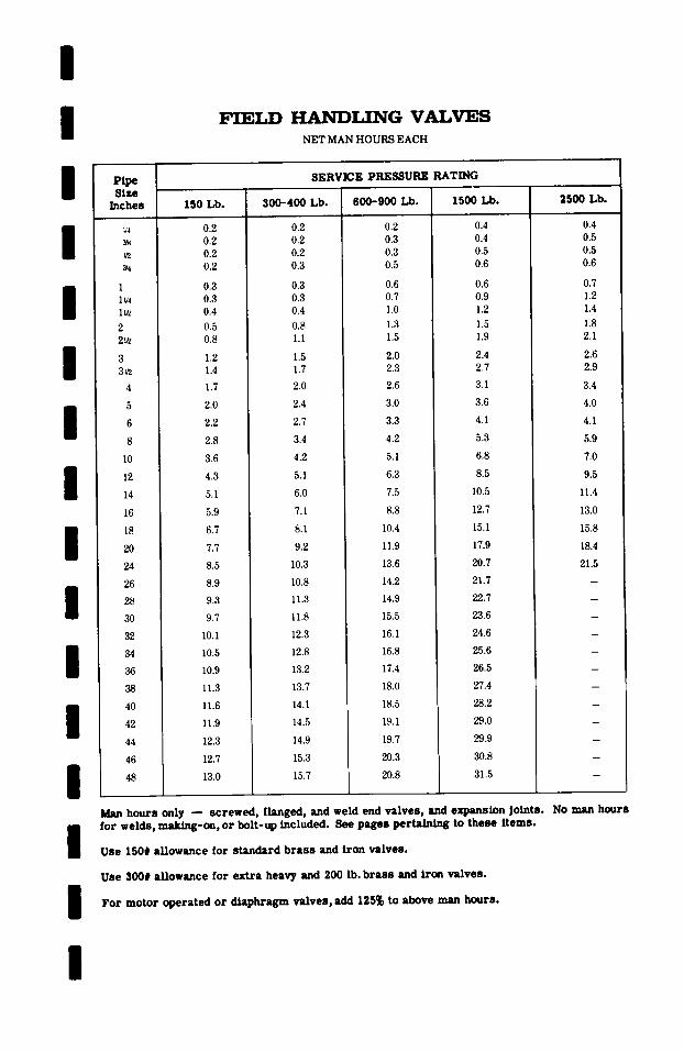
I /
H A N D L I N G VALVES NET MAN HOURS EACH
Pipe Size
Inches
/
I I / / / / / / / / /
Y2
1 1L/4 1~,2
2 2~
3 3v2
4
5
6
8
10
12
14
16
18
20
24
26
28
30
32
34
36
38
4O
42
44
46
48
I
150 Lb.
SERVICE PRESSURE RATING
300-400 Lb.
0.2 0.2 0.2 0.2 0.2 0.2 0.2 0.3
0.3 0.3 0.3 0.3 0.4 0.4
0.5 0.8 0.8 1.1
1.2 1.5 1.4 1.7
1.7 2.0
2.0 2.4
2.2 2.7
2.8 3.4
3.6 4.2
4.3 5.1
5.1 6.O
5.9 7.1
6.7 8.1
7.7 9.2
8.5 10.3
8.9 10.8
9.3 11.3
9.7 11.8
10.1 12.3
10.5 12.8
10.9 13.2
11.3 13.7
11.6 14.1
11.9 14.5
12.3 14.9
12.7 15.3
13.0 I 15.7
600-900 Lb.
0.2 0.3 0.3 0.5
0.6 0.7 1.0
1.3 1.5
2.0 2.3
2.6
3.0
3.3
4.2
5.1
6.3
7.5
8.8
10.4
11.9
13.6
14.2
14.9
15.5
16.1
16.8
17.4
18.0
18.5
19.1
19.7
20.3
20.8
1500 Lb.
0.4 0.4 0.5 0.6
0.6 0.9 1.2
1.5 1.9
2.4 2.7
3.1
3.6
4.1
5.3
6.8
8.5
10.5
12.7
15.1
17.9
20.7
21.7
22.7
23.6
24.6
25.6
26.5
27.4
28.2
29.0
29.9
30.8
31.5
2500 Lb.
0.4 0.5 0.5 0.6
0.7 1.2 1.4
1.8 2.1
2.6 2.9
3.4
4.0
4.1
5.9
7.0
9.5
11.4
13.0
15.8
18.4
21.5
Man hours only - - screwed, flanged, and weld end valves, and expansion Joints. No man hours for welds, m a k i ~ - o n , or bolt-up included. See pages pertaining to these items.
Use I50# allowance for standard brass and iron valves.
Use 300# allowance for extra heavy and 200 lb. brass and iron valves.
For motor operated or diaphragm valves, add 125% to above man hours.
/
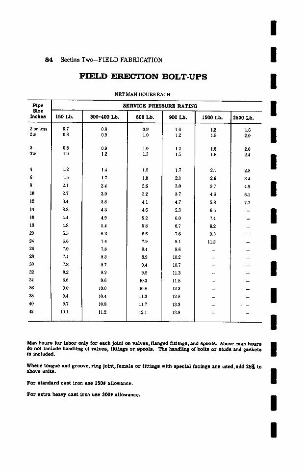
84 Section Two-FIELD FABRICATION
F I E L D E R E ~ O N B O L T - U P S
NET MAN HOURS EACH
/ / /
Pipe Size
Inches
2 or less 2vz
3 3~
4
6
8
10
12
14
16
18
20
24
26
28
30
32
34
36
38
40
42
150 Lb.
0.7 0.8
0.8 1.0
1.2
1.5
2.1
2.7
3.4
3.8
4.4
4.8
5.5
6.6
7.0
7.4
7.8
8.2
8.6
9.0
9.4
9.7
10.1
SERVICE PRESSURE RATING
300-400 Lb.
0.8 0.9
0.9 1.2
1.4
1.7
2.4
3.0
3.8
4.3
4.9
5.4
6.2
7.4
7.8
8.3
8.7
9.2
9.6
10.0
10.4
10.8
11.2
600 Lb.
0.9 1.0
1.0 1.3
1.5
1.8
2.6
3.2
4.1
4.6
5.2
5.8
6.6
7.9
8.4
8.9
9.4
9.9
10.3
10.8
11.3
11.7
12.1
900 Lb.
1.0 1.2
1.2 1.5
1.7
2.1
3.0
3.7
4.7
5.3
6.0
6.7
7.6
9.1
9.6
10.2
10.7
11.3
11.8
12.3
12.8
13.3
13.8
1500 Lb.
1.2 1.5
1.5 1.8
2.1
2.6
3.7
4.6
5.8
6.5
7.4
8.2
9.3
11.2
2500 Lb.
1.6 2.0
2.0 2.4
2.8
3.4
4.9
6.1
7.7
I I I I I l I l I
Man hours for labor only for each joint on va lves , flanged f i t t ings, and spools . Above man hours m do not include handling of va lves , f i t t ings or spools . The handling of bol ts o r s tuds and gaske t s l is included.
Where tongue and groove, r ing Joint, female or f i t t ings with spec ia l facings a r e used, add 25% to above units .
For standard cast iron use 150# allowance.
For extra heavy cast Won use 300# allowance.
/
l /
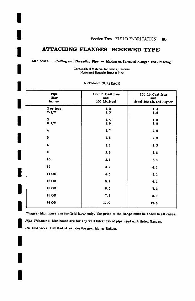
I I I I I
Section Two-FIELD FABRICATION 85
A T T A C H I N G F L A N G E S - S C R E W E D T Y P E
Man hours - - Cutting and Threading Pipe --- Making on Screwed Flanges and Refacing
Carbon Steel Material for Bends, Headers, Necks and Straight Runs of Pipe
NET MAN HOURS EACH
/
I /
I I / /
Pipe Size
Inches
2 or l ess 2-1/2
3 3-1/2
10
12
14 OD
16 OD
18 OD
20 OD
24 OD
125 Lb. Cast Iron and
150 Lb. Steel
1.2 1.3
1.4 1.6
1.7
1.8
2.1
2 .5
3.1
3 .7
4 .5
5.4
6 .5
7.7
11.0
250 Lb. Cast Iron and
Steel 300 Lb. and Higher
1.4 1.5
1.6 1.8
2.0
2.2
2.3
2.8
3.4
4.1
5.1
8.1
7.3
8.7
12.5
/ / /
FL~ges: Man hours a r e for field labor only. The p r i ce of the flange must be added in all cases .
Pfpe T~ckness: Man hours a r e for any wall th ickness of pipe used with l i s ted flanges.
Unlisted Sizes. Unlisted s izes take the next higher l isting.
/
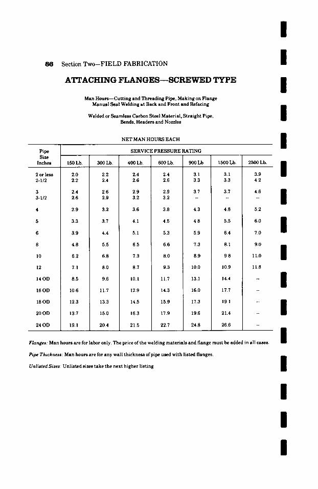
Section Two--FIELD FABRICATION
A 2 ~ A C H I N G F L A N G E S - - S C R E W E D TYPE
Man Hours- -Cut t ing and Threading Pipe, Making on Flange Manual Seal Welding at Back and Front and Refacing
Welded or Seamless Carbon Steel Material, Straight Pipe, Bends, Headers and Nozzles
NET MAN HOURS EACH
Pipe SERVICE PRESSURE RATING Size
Inches 150 Lb. 300 Lb. 400 Lb. 600 Lb. 900 Lb. 1500 Lb. 2500 Lb.
I I I I I
2 or less 2-I12
3 3-1/2
14 OD
16 OD
18 OD
20OD
24OD
2.0 2.2
2.4 2.6
2.9
3.3
3.9
4.8
6.2
7.1
8.5
10.6
12.3
13.7
19.1
2.2 2.4
2.6 2.9
3.2
3.7
4.4
5.5
6.8
8.0
9.6
11.7
13.3
15.0
20.4
2.4 2.6
2.9 3.2
3.6
4.1
5.1
6.5
7.3
8.7
I0. I
12.9
14.5
16.3
21.5
2.4 2.6
2.9 3.2
3.8
4.5
5.3
6.6
8.0
9.3
11.7
14.3
15.9
17.9
22.7
3.1 3.3
3.7 ~
4.3
4.8
5.9
7.3
8.9
10.0
13.1
16.0
17.3
19.6
24.8
3.1 3.3
3.7 ~
4.8
5.5
6.4
8.1
9.8
10.9
14.4
17.7
19.1
21.4
26.6
3.9 4.2
4.6 ~
5.2
6.0
7.0
9.0
11.0
11.8
Flanges: Man hours are for labor only. The price ofthe welding materials and flange must be added in all cases.
I I I I I I I
Pipe Thickness: Man hours are for any wall thickness ofpipe used with listed flanges.
Unlisted Sizes- Unlisted sizes take the next higher listing. I I I I

/ / / / /
l~pe
Section Two-FIELD FABRICATION 87
ATTACHING FLANGES--SCREW~ED TYPE
Man Hours- -Cut t ing and Threading Pipe, Making on Flange Manual Seal Welding at Back and Refacing
Carbon Steel Material, Straight Pipe, Bends, Headers and Nozzles
NET MAN HOURS EACH
SERVICE PRESSURE RATING
l l l l l l
Size Inches
2 or less 2-I/2
3 3-1/2
10
12
14 OD
16 OD
18 OD
20 OD
24 OD
150 Lb.
1.6 1.7
2.0 2.2
2.3
2.6
3.1
3.9
5.0
5.7
6.8
8.5
9.9
11.0
15.3
300 Lb.
1.7 2.0
2.2 2.4
2.6
3.0
3.5
4.4
5.5
6.4
7.7
9.3
10.6
11.9
16.3
400 Lb.
2.0 2.2
2.3 2.6
2.9
3.3
4.0
5.2
5.8
7.0
8.5
10.3
11.4
13.0
17.2
600 Lb.
2.0 2.2
2.3 2.6
3.0
3.6
4.3
5.3
6.4
7.6
9.6
11.3
12.5
14.3
18.4
900 Lb.
2.5 2.6
3.0 . ~
3.5
3.9
4.7
5.8
7.0
8.1
10.5
12.6
13.8
15.7
19.8
1500 Lb.
2.5 2.6
3.0 ~
3.8
4.4
5.2
6.5
7.8
9.0
12.6
13.9
15.5
17.6
21.6
2500 Lb.
3.3 3.5
3.9 ~ 1 7 6
4.2
4.9
5.7
7.3
9.8
10.0
l l l l
Flanges: Man hours are for field labor only. The price of the flange must be added in all cases.
Pipe Thickness: Man hours are for any wall thickness ofpipe used with listed flanges.
Unlisted Sizes: Unlisted sizes take the next higher listing.
l

/
Section Two-FIELD FABRICATION
ATTACHING FLANGES--SLIP-ON TYPE
Man Hours Slipping on Flange, Manual Welding at Front and Back
Carbon Steel Material, Straight Pipe, Bends, Headers and Nozzles
NET MAN HOURS EACH
Pipe Size
Inches
1 I-I/4 1-1/2
2 2-I/2
3 3-1/2
4 5 6 8 I0 12 14 O.D. 16 O.D. 18 O.D. 20 O.D. 24 O.D.
26 O.D. 30 O.D. 34 O.D. 36 O.D. 42 O.D.
150 LB.
0.9 1.0 1.0
1.3 1.5
1.8 2.2
2.4 3.0 3.6 5.1 6.3 7.7 9.0
10.5 12.2 14.6 18.3
300 LB.
1.0 1.2 1.3
1.4 1.7
2.1 2.4
2.6 3.3 3.9 5.4 6.8 8.3
10.0 11.3 13.5 16.0 20.1
SERVICE PRESSURE RATING
400 LB. 600 LB. 900 LB.
1.4 1.4 1.6 1.4 1.4 1.8 1.4 1.4 1.8
1.8 1.8 2.4 2.3 2.3 3.0
2.9 2.9 3.6 3.3 3.3 --
3.5 3.8 4.8 4.5 4.8 6.1 5.2 5.9 7.2 7.3 8.0 9.9 9.0 11.1 12.5
11.0 13.7 15.3 13.0 16.2 17.7 15.0 18.4 20.1 17.5 21.1 23.7 21.1 23.7 27.5 25.6 31.2 34.8
27.7 33.7 37.8 32.0 38.9 43.5 36.2 44.1 49.3 38.4 46.7 52.2 44.7 54.5
1500 LB.
1.8 2.1 2.1
2.7 3.3
4.0 ~ 1 7 6
5.4 6.7 8.1
2500 LB.
2.1 2.3 2.3
3.0 3.6
4.4 . .
5.9 7.4 8.9
11.0 14.0 17.2 19.8 22.4 26.6 30.8 38.9
12.0 15.5 19.0
. .
. .
~
* *
Flanges: Man hours are for field labor only. The price of welding materials and the flange must be added in all C ~ .
Pipe Thickness: Man hours are for any wall thickness of pipe used with listed flanges.
Preheating: If specified or required by codes, add for this operation. See man hours for pre-heating.
Stress Relieving: If specified or required by codes, add for this operation. See man hours for stress relieving.
Unlisted Sizes: Unlisted sizes take the next higher listing.
/ / / / /
I / /
I / / /
I / /
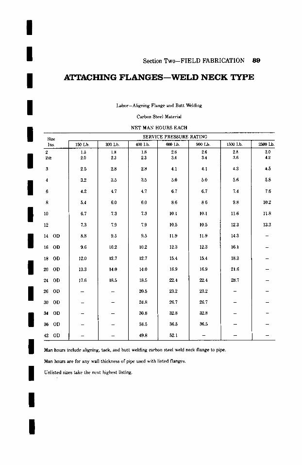
l l l
Section Two-FIELD FABRICATION
A T T A C H I N G F L A N G E S - - W E L D N E C K T Y P E
/
/ Size
Labor-Aligning Flange and Butt Welding
Carbon Steel Materi',d
NET MAN HOURS EACH
SERVICE PRESSURE RATING
Ins.
2
3
4
/ ~ 8
~o
12
/ 14 OD
16 OD
/ /
18 OD
20 OD
24 OD
26 OD
30 OD
3 4 0 D
36 OD
42 OD
150 Lb.
1.5 2.0
2.5
3.2
4.2
5.4
6.7
7.3
8.8
9.6
12.0
13.3
17.6
300 Lb.
1.8 2.3
2.8
3.5
4.7
6.0
7.3
7.9
9.5
10.2
12.7
14.0
18.5
400 Lb.
1.8 2.3
2.8
3.5
4.7
6.0
7.3
7.9
9.5
10.2
12.7
14.0
18.5
20.5
24.8
30.8
34.5
49.8
600 Lb.
2.6 3.4
4.1
5.0
6.7
8.6
10.1
10.5
11.9
12.3
15.4
16.9
22.4
23.2
26.7
32.8
36.5
52.1
900 Lb.
2.6 3.4
4.1
5.0
6.7
8.6
10.1
10.5
11.9
12.3
15.4
16.9
22.4
23.2
26.7
32.8
36.5
/ Man hours include aligning, tack, and butt welding carbon steel weld neck flange to pipe.
1500 I,b.
2.8 3.6
4.3
5.6
7.4
9.8
11.6
12.3
14.3
16.1
18.3
21.6
28.7
2500 Lb.
3.0 4.2
4.5
5.8
7.6
10.2
11.8
13.3
/ /
Man hours are for any wall thickness of pipe used with listed flanges.
Unlisted sizes take the next highest listing.
/
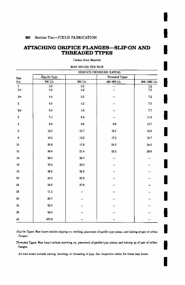
/
90 Section Two-FIELD FABRICATION
ATTACHING ORIFICE F L A N G E S - - S L I P - O N A N D T H R E A D E D T Y P E S
Carbon Steel Material
MAN HOURS PER PAIR
/
/
/ SERVICE PRESSURE RATING
Size Slip-On Type Threaded Types
Ins. 300 Lb. 300 Lb. 400-600 Lb. 900-1500 Lb.
1 lv4
lu2
2~z
10
12
20
24
26
30
36
42
3.8 4.2
4.4
4.6
5.3
7.1
8.6
12.0
16.2
20.6
24.4
29.3
33.5
38.2
45.2
54.6
71.2
80.7
92.0
98.8
107.6
5.2 5.2
5.2
5.2
5.8
6.3
8.6
10.7
13.2
17.0
21.4
24.7
28.3
32.6
37.0
47.0
9.8
12.4
17.2
21.0
25.2
7.2 7.2
7.2
7.2
7.7
11.0
12.7
16.0
19.7
/
/
/
/
28.8
/ /
/
/
Slip-On Types: Man hours include slipping on, welding, placement of paddle-type plates, and bolting of pair of orifice
flanges.
/ Threaded Types: Man hours include screwing on, placement of paddle-type plates, and bolting up of pair of orifice E
| flanges.
All man hours exclude cutting, beveling, or threading of pipe. See respective tables for these man hours.
/
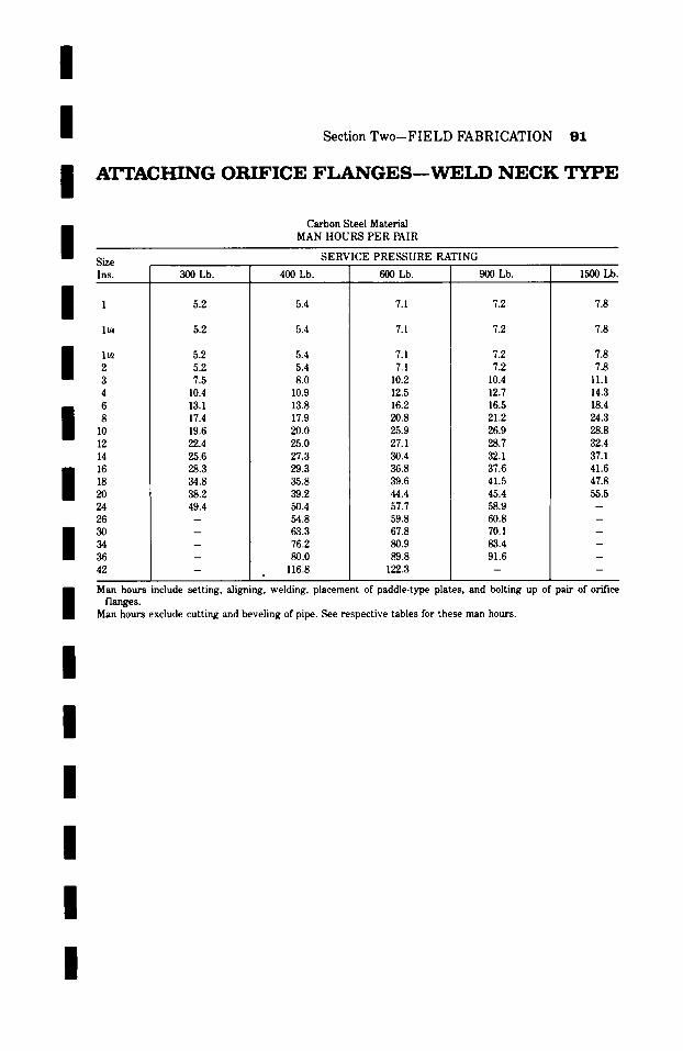
/ / /
Section Two-FIELD FABRICATION 91
A T T A C H I N G OR I FI C E F L A N G E S - - ~ L D N E C K T Y P E
Carbon Steel Material MAN HOURS PER PAIR /
Si~ Ins.
/ 1
1~ 2 3 4 6
10 12 14 16 18 20
30 34 36
SERVICE PRESSURE RATING
300 Lb. 400 Lb. 600 Lb. 900 Lb. 1500 Lb.
5.2
5.2
5.2 5.2 7.5
10.4 13.1 17.4 19.6 22.4 25.6 28.3 34.8 38.2 49.4
5.4
5.4
5.4 5.4 8.0
10.9 13.8 17.9 20.0 25.0 27.3 29.3 35.8 39.2 50.4 54.8 63.3 76.2 80.0
116.8
7.1
7.1
7.1 7.1
10.2 12.5 16.2 20.8 25.9 27.1 30.4 36.8 39.6 44.4 57.7 59.8 67.8 80.9 89.8
122.3
7.2
7.2
7.2 7.2
10.4 12.7 16.5 21.2 26.9 28.7 32.1 37.6 41.5 45.4 58.9 60.8 70.1 83.4 91.6
7.8
7.8
7.8 7.8
11.1 14.3 18.4 24.3 28.8 32.4 37.1 41.6 47.8 55.5
Man hours include setting, aligning, welding, placement of paddle-type plates, and bolting up of pair of orifice flanges.
Man hours exclude cutting and beveling of pipe. See respective tables for these man hours.
I / /
/ /
I
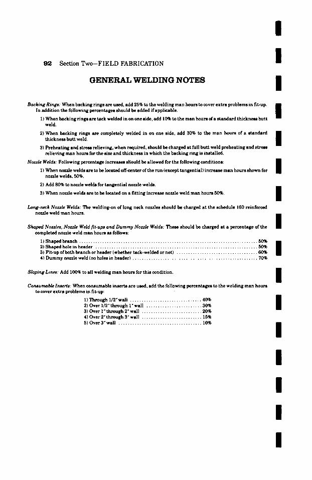
I
9 2 Section Two--FIELD FABRICATION
GENERAL WELDING NOTES
/
/ Backing Rings: When backing rings are used, add 25% to the welding man hours to cover extra problems in fit-up. �9
In addition the following percentages should be added if applicable. | 1) When backing rings are tack welded in on one side, add 10% to the man hours of a standard thickness butt
weld.
2) When backing rings are completely welded in on one side, add 30% to the man hours of a standard thickness butt weld.
3) Preheating and stress relieving, when required, should be charged at full butt weld preheating and stress relieving man hours for the size and thickness in which the backing ring is installed.
I Nozzle Welds: Following percentage increases should be allowed for the following conditions: R
| 1) When nozzle welds are to be located off-center of the run (except tangential) increase man hours shown for nozzle welds, 50%.
2) Add 80% to nozzle welds for tangential nozzle welds.
3) When nozzle welds are to be located on a fitting increase nozzle weld man hours 50%.
Long-neck Nozzle Welds: The welding-on of long neck nozzles should be charged at the schedule 160 reinforced nozzle weld man hours.
Shaped Nozzles, Nozzle Weld fit-ups and Dummy Nozzle Welds: These should be charged at a percentage of the completed nozzle weld man hours as follows:
1) Shaped branch . . . . . . . . . . . . . . . . . . . . . . . . . . . . . . . . . . . . . . . . . . . . . . . . . . . . . . . . . . . . . . . . . . . . . . . . . . . . . 50% 2) Shaped hole in header . . . . . . . . . . . . . . . . . . . . . . . . . . . . . . . . . . . . . . . . . . . . . . . . . . . . . . . . . . . . . . . . . . . . . . 50% 3) Fit-up of both branch or header (whether tack-welded or not) . . . . . . . . . . . . . . . . . . . . . . . . . . . . . . . . . . . 60% 4) Dummy nozzle weld (no holes in header) . . . . . . . . . . . . . . . . . . . . . . . . . . . . . . . . . . . . . . . . . . . . . . . . . . . . . . 70%
Sloping Lines: Add 100~ to all welding man hours for this condition.
Consumable Inserts: When consumable inserts are used, add the following percentages to the welding man hours to cover extra problems in fit-up:
1) Through 1/2 N wall . . . . . . . . . . . . . . . . . . . . . . . . . . . . . . . 40% 2) Over 1/2" through 1" wall . . . . . . . . . . . . . . . . . . . . . . . . 30% 3) Over 1" through 2" wall . . . . . . . . . . . . . . . . . . . . . . . . . . 20% 4) Over 2" through 3" wall . . . . . . . . . . . . . . . . . . . . . . . . . . 15% 5) Over 3" wall . . . . . . . . . . . . . . . . . . . . . . . . . . . . . . . . . . . . 10%
l
/ / / /
/
/
/
/
l
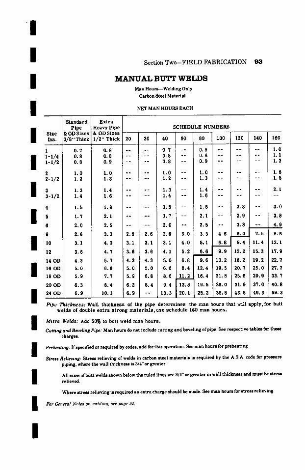
/
/ Section Two--FIELD FABRICATION 93
/
/
M A N U A L B U ' I T W E L D S
Man Hours--Welding Only
Carbon Steel Material
NET MAN HOURS EACH
I Size Ins .
1 I 1-I/4 x-x/2
2 2-x/2
I ~-i12 4
6 8 / 12
14 OD
m 16 OD 18 OD
20 OD
I 24 OD
Standard Pipe
& OD Sizes 3 / 8 " Th i ck
0 . 7 0 . 8 0 . 8
1 .0 1 .2
1 .3 1 .4
1 .5
1 .7
2 . 0
2 .6
3 .1
3 . 6
4 . 3
5 . 0
5 . 9
6 . 3
6 . 9
E x t r a Heavy P i p e & OD S izes 1 / 2 " Th i ck
S C H E D U L E NUMBERS P
2o I 30 4o 6o so 100 /~20 '140 160 . l 0 # t ! ! ! "
0 . 8 . . . . . 0 . 7 - - 0 . 8 . . . . . . . 1 . 0 0 . 8 . . . . . 0 . 8 - - 0 . 8 . . . . . . 1 . 1 0 . 9 - - ; - - 0 . 8 - - 0 . 9 . . . . . . 1 .3
1 . 0 . . . . . 1 . 0 - - 1 .0 . . . . . . 1 .6 1 .3 . . . . . 1 .2 - - 1 .3 . . . . . . 1 .8
1 .4 . . . . . 1 .3 - - 1 .4 . . . . . . 2 .1 1 .6 . . . . . 1 .4 - - 1 .6 . . . . . . . .
1 .8 . . . . . 1 .5 - - 1 .8 - - 2 . 8 I - - 3 . 0 i
2 .1 . . . . . 1 .7 - - 2.'1. - - 2 . 9 - - 3 . 8
2 . 5 . . . . . 2 . 0 - - 2 . 5 - - 3 . 8 - - 4 . 9 i'
3 . 3 2 .6 I 2 . 6 2 . 6 3 . 0 3 . 3 4 . 6 6 . 0 l 7 . 5 8 . 6 2
4 . 0 3 .1 i 3 .1 3 .1 4 . 0 5 .1 6 . 8 1 9 . 4 11 .4 13.1 i f |
4 . 7 3 .6 3 .6 4 . 1 5 .2 , 6 . 6 ~ 9 . 9 12 .2 15 .3 1 7 . 9
5 .7 4 . 3 4 . 3 5 . 0 6 . 8 9 . 6 13 .2 16 .2 19 .2 2 2 . 7
6 . 6 5 . 0 5 . 0 6 . 6 8 . 4 12 .4 19 .5 20 .7 2 5 . 0 2 7 . 7
7 . 7 5 . 9 6 . 8 8 . 6 11 .2 16 .4 2 1 . 8 2 5 . 6 2 9 . 9 33 .7 ' ' t
8 .4 6 . 3 8 . 4 9 . 4 13 .8 19 .5 2 6 . 0 3 1 . 9 3 7 . 0 4 0 . 8 l
10.1 6 . 9 - - 13 .3 20 .1 2 5 . 2 3 5 . 8 4 3 . 5 4 9 . 3 59 .3
Pipe Thickness: Wal l t h i c k n e s s of the p ipe d e t e r m i n e s the man h o u r s tha t wi l l app ly , for but t we ld s of double e x t r a s t r o n g m a t e r i a l s , u se s c h e d u l e 160 man h o u r s .
I Mitre Welds: Add 50% to but t we ld man h o u r s .
Cutting and Beveling Pipe: Man hours do not include cutting and beveling of pipe. See respective tables for these
charges.
I Preheating: If specified or required by codes, add for this operation. See man hours for preheating.
Stress Relieving: Stress relieving of welds in carbon steel materials is required by the A.S.A. code for pressure piping, where the wall thickness is 3/4" or greater.
I All sizes of butt welds shown below the ruled lines are 314" or greater in wall thickness and must be stress relieved.
Where stress relieving is required an extra charge should be made. See man hours for stress relieving.
I For General Notes on welding, see page 92.
I
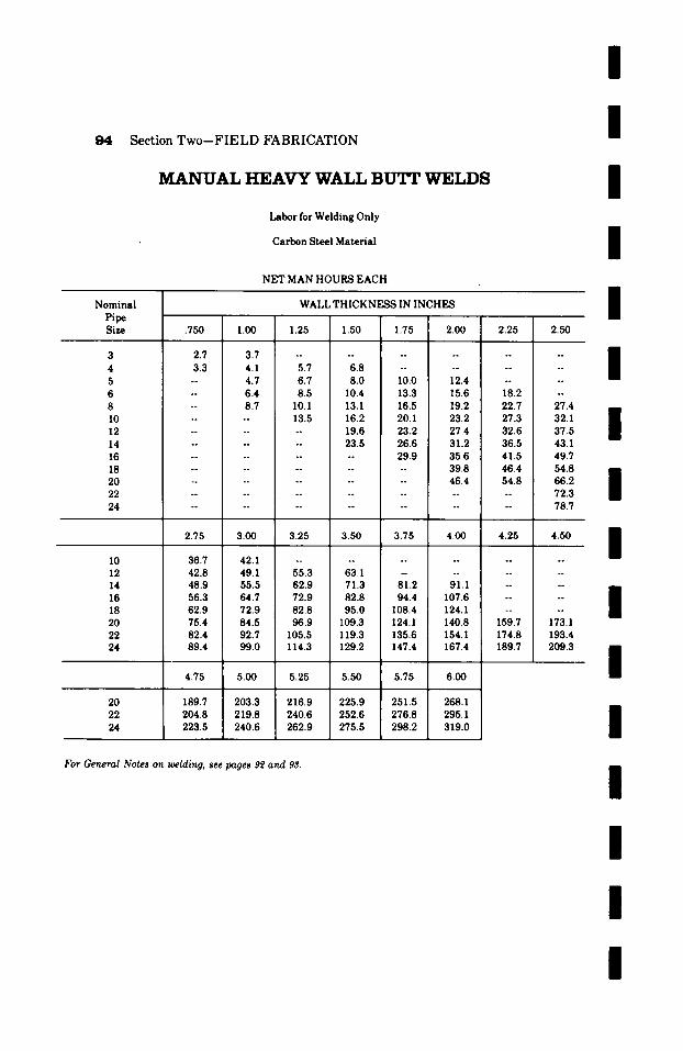
/
Section Two--FIELD FABRICATION
MANUAL HEAVY WALL B U'IT WELDS
Labor for Welding Only
Carbon Steel Material
NET MAN HOURS EACH
I
I
I m
N o m i n a l WALL T H I C K N E S S IN I N C H E S BB Bi Pipe
Size .750 1.00 1.25 1.50 1.75 2.00 2.25 2.50 e
3 2.7 3.7 . . . . . . . . . . . .
| 4 3.3 4.1 5.7 6.8 . . . . . . . . 5 -- 4.7 6.7 8.0 10.0 12.4 . . . . 6 -- 6.4 8.5 10.4 13.3 15.6 18.2 -- 8 -- 8.7 10.1 13.1 16.5 19.2 22.7 27.4 i
10 . . . . 13.5 16.2 20.1 23.2 27.3 32.1 i 12 . . . . . . 19.6 23.2 27.4 32.6 37.5 g 14 . . . . . . 23.5 26.6 31.2 36.5 43.1 16 . . . . . . . . 29.9 35.6 41.5 49.7
18 . . . . . . . . . . 39.8 46.4 54.8 NB 20 . . . . . . . . . . 46.4 54.8 66.2 I 22 . . . . . . . . . . . . . . 72.3 24 . . . . . . . . . . . . . . 78.7
2.75 3.00 3.25 3.50 3.75 4.00 4.25 4.50
I0 36.7 42. I . . . . . . . . . . . . 12 42.8 49.1 55.3 63.1 . . . . . . . . 14 48.9 55.5 62.9 71.3 81.2 91.1 . . . . 16 56.3 64.7 72.9 82.8 94.4 107.6 . . . . 18 62.9 72.9 82.8 95.0 108.4 124.1 . . . . 20 75.4 84.5 96.9 109.3 124.1 140.8 159.7 173.1 22 82.4 92.7 105.5 119.3 135.6 154. I 174.8 193.4 24 89.4 99.0 114.3 129.2 147.4 167.4 189.7 209.3
4.75 5.00 5.25 5.50 5.75 6.00
20 189.7 203.3 216.9 225.9 251.5 268.1 22 204.8 219.8 240.6 252.6 276.8 295. I 24 223.5 240.6 262.9 275.5 298.2 319.0
For C_,eneml Notes on welding, see pages 9~ and 93.
I
I
I
I
I
I
I
I
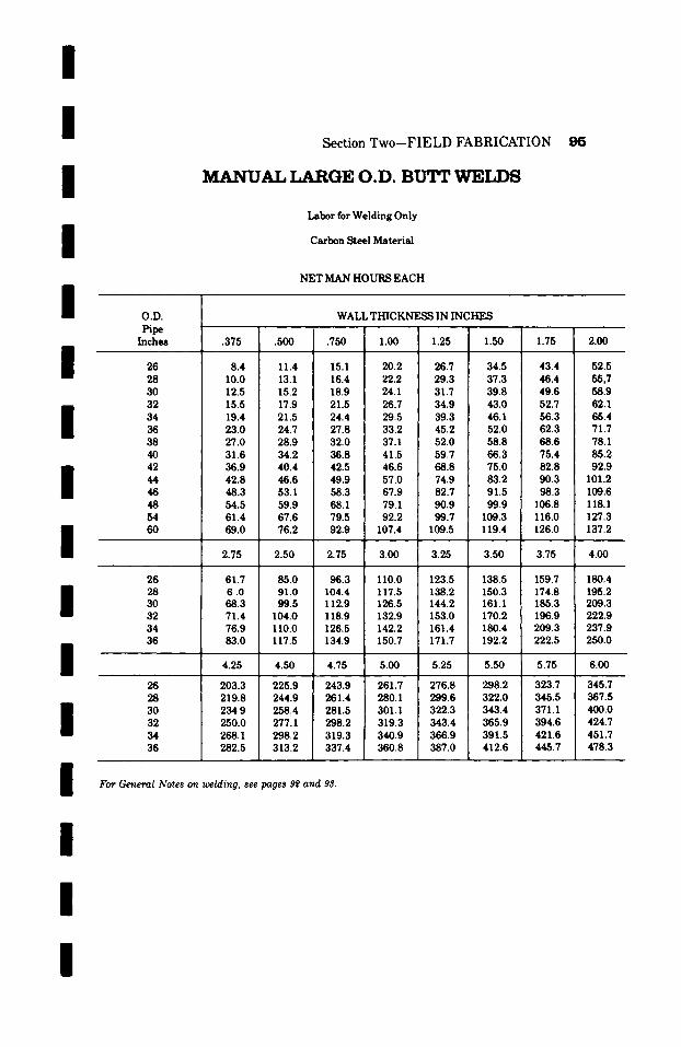
/ / / / / / / I i / / / / /
I
Section Two-FIELD FABRICATION 9 5
MANUAL LARGE O.D. B U T t WrETJ"~3
Labor for Welding Only
Carbon Steel Material
NET MAN HOURS EACH
O.D. WALL THICKNESS IN INCHES Pipe
Inches .375 .500 .750 1.00 1.25 1.50 1.75 2.00
26 8.4 11.4 15.1 20.2 26.7 34.5 43.4 52.5 28 10.0 13.1 16.4 22.2 29.3 37.3 46.4 55,7 30 12.5 15.2 18.9 24.1 31.7 39.8 49.6 58.9 32 15.5 17.9 21.5 26.7 34.9 43.0 52.7 62.1 34 19.4 21.5 24.4 29.5 39.3 46.1 56.3 65.4 36 23.0 24.7 27.8 33.2 45.2 52.0 62.3 71.7 38 27.0 28.9 32.0 37.1 52.0 58.8 68.6 78.1 40 31.6 34.2 36.8 41.5 59.7 66.3 75.4 85.2 42 36.9 40.4 42.5 46.6 68.8 75.0 82.8 92.9 44 42.8 46.6 49.9 57.0 74.9 83.2 90.3 101.2 46 48.3 53.1 58.3 67.9 82.7 91.5 98.3 109.6 48 54.5 59.9 68.1 79.1 90.9 99.9 106.8 118.1 54 61.4 67.6 79.5 92.2 99.7 109.3 116.0 127.3 60 69.0 76.2 92.9 107.4 109.5 119.4 126.0 137.2
2.75 2.50 2.75 3.00 3.25 3.50 3.75 4.00
26 61.7 85.0 96.3 110.0 123.5 138.5 159.7 180.4 28 6 .0 91.0 104.4 117.5 138.2 150.3 174.8 195.2 30 68.3 99.5 112.9 126.5 144.2 161.1 185.3 209.3 32 71.4 104.0 118.9 132.9 153.0 170.2 196.9 222.9 34 76.9 110.0 126.5 142.2 161.4 180.4 209.3 237.9 36 83.0 117.5 134.9 150.7 171.7 192.2 222.5 250.0
4.25 4.50 4.75 5.00 5.25 5.50 5.75 6.00
26 203.3 225.9 243.9 261.7 276.8 298.2 323.7 345.7 28 219.8 244.9 26 1.4 280.1 299.6 322.0 345.5 367.5 30 234.9 258.4 281.5 301.1 322.3 343.4 371.1 400.0 32 250.0 277.1 298.2 319.3 343.4 365.9 394.6 424.7 34 268.1 298.2 319.3 340.9 366.9 391.5 421.6 451.7 36 282.5 313.2 337.4 360.8 387.0 412.6 445.7 478.3
For General Notes on welding, see pages ~ and 93.
I

/
9 6 Section Two--FIELD FABRICATION
9 0 ~ W E L D E D N O Z Z L E S Labor for Cut t ing and Welding Carbon Steel Mater ial
NET MAN HOURS EACH
I
I
Size Ins.
1 1-1/4 1-1/2
2 2-I/2
3 3-1/2
10
12
14OD
16OD
18OD
20OD
24OD
Standard Pipe
& OD Sizes 3/8"Thick
2.1 2.2 2.4
2.5 2.8
3.2 3.7
4.0
5.1
5.4
6.3
7.1
8.1
9.3
10.6
11.6
13.0
14.2
Extra Heavy Pipe & OD Sizes I/2"Thick
SCHEDULE NUMBERS
20 30 40 60 80 100 120 140 160
2.2 -- - 2.1 -- 2.2 -- 3.1 2.4 . . . . 2.2 -- 2.4 - 3.6 i
2.6 -- - 2.4 -- 2.6 - 4.0
3.1 . . . . 2.5 -- 3.1 -- 5.3 3.8 . . . . 2.8 -- 3.8 -- 5.9
4.4 -- 3.2 -- 4.4 -- 6.6 4.9 -- 3.7 - 4 . 9 --
5.6 - 4.0 -- 5.6 7.0 -- 8.6
6.9 -- 5.1 - 6.9 8.6 -- 10.7
7.5 -- 5.4 -- 7.5
8.9 6.3 6.3 6.3 8.3 8.9 12.0
10.3 7.1 7.1 7.1 10.3 12.6 16.4
10.9 -- 13.9
21.1 27.~ 32.8
11.8 8.1 8.1 9.9 13.1 17.0 I[ 23.5 28.7 34.7 39.2
13.6 9.3 9.3 11.6 16.0 22.7 28.9 34.6 38.9 47.9
15.2 10.6 10.6 15.2 2 0 . 2 26.8 36.5 41.4 45.7 55.3
16.3 11.6 15.1 i 19.1 2 5 . 4 30.1 44.1 49.0 53.0 69.2
18.3 13.0 18.3 22.3 32.6 35.4 51.0 55.9 60.8 77.7
19.8 14.2 21.2 27.7 41.7! 46.0 64.8 69.71 77.8 90.9
All nozzles other than 90 ~ be charged at the man hours shown for 45 ~ nozzles.
Pipe Thickness: Wall thickness of the pipe used for the nozzle determines the man hours tha t will apply. For nozzles of double extra strong pipe thickness, use schedule 160 man hours.
Reinforcement: Man hours given above are for plain welded nozzles only. For use ofgusset plates, etc., as stiffeners not for reinforcement, add 25% to the net man hours shown above. If reinforcement is required and produced by building up the nozzle weld, or by the use of reinforcing rings or saddles as specified use man hours for 90 ~ reinforced nozzles.
Preheating: If specified or required by codes, add for this operation. See man hours for preheating. The size and wall thickness of the header (not the size of the nozzle) determines the preheat ing man hours.
Stress Relieving: Stress relieving of welds in carbon steel mater ia ls is required by the A.S.A. code for pressure piping, where the wall thickness is 3/4" or greater . The size and wall thickness ofthe header determines the man hours to be used for stress relieving.
All pipe sizes shown below the ruled line are 3/4" or grea ter in wall thickness and must be stress relieved. Where stress relieving is required an extra charge should be made. See man hours for stress relieving.
For General Notes on welding, see page 9~.
I
I
I
I
I I
I
I
I
I
I
I
I
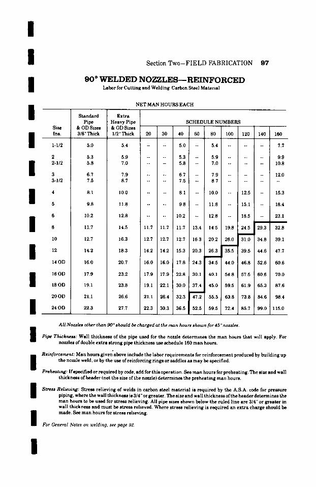
/
/ /
I
I /
/ /
I / / /
/
I /
Section Two-FIELD FABRICATION 97
9 0 ~ W E L D E D N O Z Z L E S - - R E I N F O R C E D Labor for Cut t ing and Welding Carbon Steel Material
NET MAN HOURS EACH
Size Ins.
I-I/2
2 2-I/2
3 3-1/2
10
12
14 OD
16 OD
18 OD
20OD
24 OD
Standard Pipe
& OD Sizes 3/8" Thick
5.0
5.3 5.8
6.7 7.5
8 . 1
9 . 8
10.2
11.7
12.7
14.2
Extra Heavy Pipe & OD Sizes l /2"Thick
SCHEDULE NUMBERS
20 30 40 60 80 100 120 140 160
5.4 . . . . 5.0 -- 5.4 . . . . . . 7.7
5.9 . . . . 5.3 -- 5.9 . . . . . . 9.9 7.0 . . . . 5.8 -- 7.0 . . . . . . 10.8
7.9 6.7 -- 7.9 . . . . . 12.0 8.7 7.5 -- 8.7 . . . . . . . .
I 0 . 0 . . . . 8 . 1 - - 1 0 . 0 - - 1 2 . 5 - - 1 5 . 3
1 1 . 8 . . . . 9 . 8 - - 1 1 . 8 - - 1 5 . 1 - - 1 8 . 4
16.0
17.9
19.1
21.1
22.3
12.8 . . . . 10.2 -- 12.8 -- 18.5 -- 23.1
14.5 11.7 11.7 11.7 13.4 14.5 19.8 24.5 29.3 32.8
16.3 12.7 12.7 12.7 16.3 20.2 26.0 [ 31.0 34.8 39.1 |
I
18.3 14.2 14.2 15.3 20.3 26.3 35.5 39.5 44.6 47.7
20.7 16.0 16.0 17.8 24.3 34.5 44.0 46.8 52.6 60.6
23.2 17.9 17.9 22.8 30.1 40.1 54.8 57.5 60.6 70.0
23.8 19.1 22.1 30.0 37.4 45.0 59.5 61.9 65.3 87.6
26.6 21.1 26.4 32.3 47.2 55.5 63.8 73.8 84.6 98.4
27.7 22.3 30.3 3 6 . 5 5 2 . 5 ' 5 9 . 5 72.4 85.7 99.0 115.0
All Nozzles other than 90 o should be charged at the man hours shown for 45 ~ nozzles.
Pipe Thickness: Wall th ickness of the pipe used for the nozzle determines the man hours tha t will apply. For nozzles of double extra strong pipe thickness use schedule 160 man hours.
Reinforcement: Man hours given above include the labor requi rements for reinforcement produced by building up the nozzle weld, or by the use of reinforcing r ings or saddles as may be specified.
Preheating: Ifspecified or required by code, add for this operation. See man hours for preheat ing. The size and wall th ickness of header (not the size of the nozzle) determines the prehea t ing man hours.
Stress Relieving: Stress rel ieving of welds in carbon steel mater ia l is required by the A.S.A. code for pressure piping, where the wall thickness is 3/4" or greater. The size and wall th ickness of the header determines the man hours to be used for stress relieving. All pipe sizes shown below the ruled line are 3/4" or grea ter in wall thickness and must be stress relieved. Where stress relieving is required an ext ra charge should be made. See man hours for stress relieving.
For General Notes r melding, see page 9"2.
I
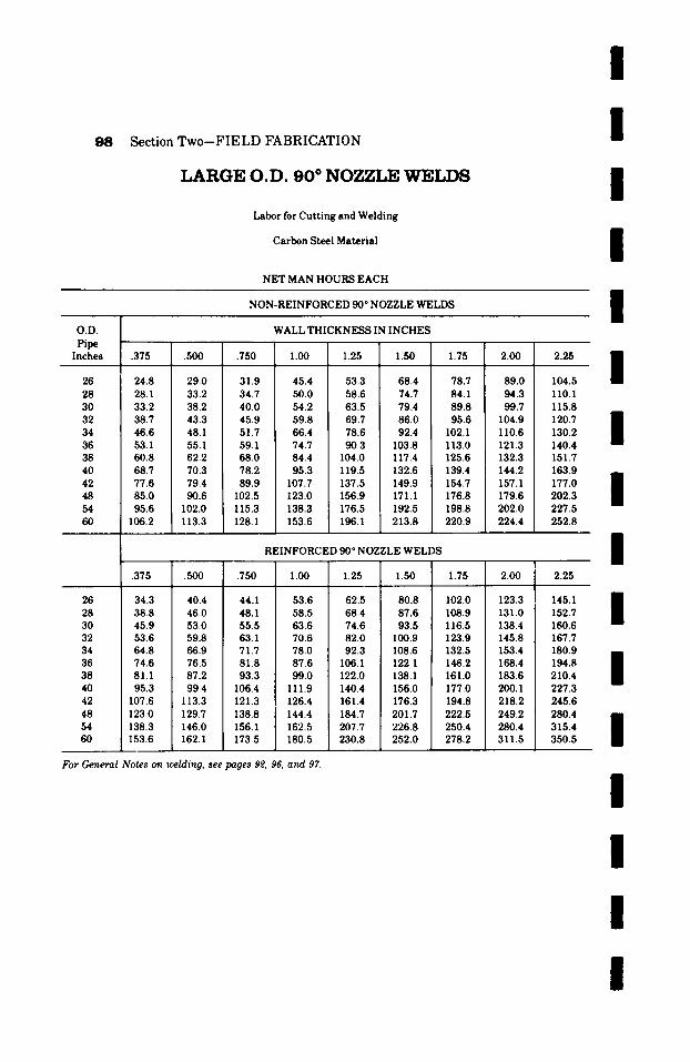
/
Section Two--FIELD FABRICATION
L A R G E O . D . 9 0 ~ N O Z Z L E W E L D S
Labor for Cutting and Welding
Carbon Steel Material
NET MAN HOURS EACH
NON-REINFORCED 90 ~ NOZZLE WELDS
I I i i
O.D. tripe Inches
26 28 30 32 34 36 38 40 42 48 54 60
26 28 30 32 34 36 38 40 42 48 54 60
.375 .500 .750
24.8 29.0 31.9 28.1 33.2 34.7 33.2 38.2 40.0 38.7 43.3 45.9 46.6 48.1 51.7 53.1 55.1 59.1 60.8 62.2 68.0 68.7 70.3 78.2 77.6 79.4 89.9 85.0 90.6 102.5 95.6 102.0 115.3
106.2 113.3 128.1
.375 .500 .750
WALL THICKNESS IN INCHES
1.00 1.25 1.50 1.75 2.00
45.4 53.3 68.4 78.7 89.0 50.0 58.6 74.7 84.1 94.3 54.2 63.5 79.4 89.8 99.7 59.8 69.7 86.0 95.6 104.9 66.4 78.6 92.4 102.1 110.6 74.7 90.3 103.8 113.0 121.3 84.4 104.0 117.4 125.6 132.3 95.3 119.5 132.6 139.4 144.2
107.7 137.5 149.9 154.7 157.1 123.0 156.9 171.1 176.8 179.6 138.3 176.5 192.5 198.8 202.0 153.6 196.1 213.8 220.9 224.4
REINFORCED 90 ~ NOZZLE WELDS
1.00 1.25 1.50 1.75 2.00
34.3 40.4 44.1 53.6 62.5 80.8 102.0 123.3 38.8 46.0 48.1 58.5 68.4 87.6 108.9 131.0 45.9 53.0 55.5 63.6 74.6 93.5 116.5 138.4 53.6 59.8 63.1 70.6 82.0 100.9 123.9 145.8 64.8 66.9 71.7 78.0 92.3 108.6 132.5 153.4 74.6 76.5 81.8 87.6 106.1 122.1 146.2 168.4 81.1 87.2 93.3 99.0 122.0 138.1 161.0 183.6 95.3 99.4 106.4 111.9 140.4 156.0 177.0 200.1
107.6 113.3 121.3 126.4 161.4 176.3 194.8 218.2 123.0 129.7 138.8 144.4 184.7 201.7 222.5 249.2 138.3 146.0 156.1 162.5 207.7 226.8 250.4 280.4 153.6 162.1 173.5 180.5 230.8 252.0 278.2 311.5
For General Notes on welding, see pages 9~, 96, and 97.
2.25
104.5 110.1 115.8 120.7 130.2 140.4 151.7 163.9 177.0 202.3 227.5 252.8
2.25
145.1 152.7 160.6 167.7 180.9 194.8 210.4 227.3 245.6 280.4 315.4 350.5
i i i i / / / i i i
i

/ /
Section Two-FIELD FABRICATION 99
/ /
4 5 ~ W E L D E D N O Z Z L E S
Labor for Cutting and Welding
Carbon Steel Material
NET MAN HOURS EACH
Standard Extra Pipe Heavy Pipe
Size & OD Sizes & OD Sizes . . . . . . . 1 Ins. 3 / 8 " T h i c k 1 / 2 " T h i c k 20 30 40 / 60 80 100 120 140 160
I I ' . . . . . .
2 . 8 2 . 9 I . . . . 2 . 8 - - 2 . 9 . . . . . . 4 . 1 - 1 / 4 2 . 9 3 . 2 . . . . 2 . 9 - - 3 . 2 - . . . . . 4 . 7
1 - 1 / 2 3 . 2 3 . 6 . . . . 3 . 2 i - - 3 . 8 . . . . . . 5 . 4
SCHEDULE NUMBERS
I 2 3 . 3 4 . 1 . . . . 3 . 3 - - 4 . 1 . . . . . . 7. I 2 - I / 2 3 . 8 5. I . . . . 3 . 8 - - 5. I . . . . . . 7 . 9
3 3-I/2
I 4 5.5 7 . e . . . . 5 . 5 - - 7 . e - - ~ . 4 - - I~.4 i
~ ~ , . . . . ~ . . ~ , _ . , , ~ . . , ,
, , ~ ~ , , o o . . . . ~ - - , o o - - , , ~ - - , ,
[ 8 8.8 11.7 8.8 8.6 8.8 11.1 11.7 15.9 2 0 . 1 | 25.1 28.8
10 9.6 13.7 9.6 9.6 9.6 13.7 16.6 21.8 | 9,8.1 36.2 43.7 ! [
12 1 0 . 9 1 5 . ? 1 0 . 9 1 0 . 9 1 3 . 0 1 7 . 5 , 2 2 . 9 2 4 . 2 3 8 . 6 4 5 . ? 5 2 . 2
, , o o , 5 , , o , . ,
24 OD 18.8 26.6 18.8 31.8 35.5 48.0 55.0 86.8 93.4 104.3 121.8 L
I I I I
4 . 4 5 . 9 . . . . 4 . 4 - - 5 . 9 . . . . . . 8 . 9 4 . 9 6 . 4 . . . . 4 . 9 - - 8 . 4 . . . . . . . .
P ~ ~ c ~ s s : WaU thickness of the pipe used for the nozzle determines the man hours that will apply. For nozzles of double extra strong pipe thickness, use schedule 180 man hours.
Re~forcem~t: Man hours given above are for plain nozzles only. For use of gmmet plates, etc. , a s stiffeners, not for reinforcement, add 25~ to the net man hours shown above. If reinforcement is required and produced by building up the nozzle weld, or by the use of reinforcing rings or saddles as specified use man hours for 45 ~ reinforced nozzles.
PreheaHng: If specified or required by codes, add for this oDeraflon. See man hours for pre- heating. The size and wall thickness of the header (not the size of the nozzle) determines the preheating man hom-s.
Stress l ~ l ~ t ~ . Stress relieving of welds in carbon steel mater ial is required by the A. S. A. code for p ressu re piping, where the wall thickness is 3/4" or greater . The size and wall thickness of the header determines the man hours to be used for s t r e s s relieving. All pipe sizes shown below the ruled line are 3/4" or greater In wall thickness and must be s t r e s s relieved. Where s t r e s s relieving is required an extra charge should be made. See man hours for s t r e s s relieving.
Noter For additional notes on welding see page 92.
/
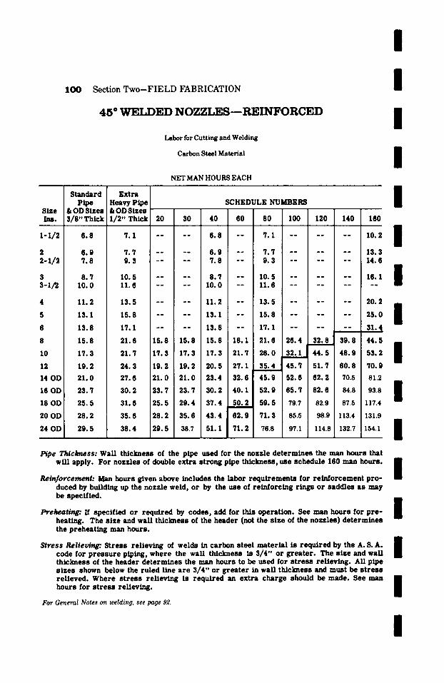
I
1OO Section Two-FIELD FABRICATION /
4 5 ~ W E L D E D N O Z Z L E S - - R E I N F O R C E D
Labor for Cutting and Welding
Carbon Steel Material
NET MAN HOURS EACH
Size Ins.
~-1/2
2-1/2
3 3-1/~
4
5
6
8
10
12
14 OD
16 OD
18 OD
20 OD
24 OD
Standard p~e
& OD Sizes 3/8,, Th~k
Extra Heavy Pipe &ODSizes 1 /2" Thick 20 30 40
7.1 . . . . 6 .8
7 .7 . . . . 6 .9 9.3 . . . . 7 .8
10.5 . . . . 8 .7 11.6 . . . . 10.0
13.5 . . . . 11.2
15.8 . . . . 13.1
17 .1 . . . . 1 3 . 8
21.6 15.8 15.8 15.8
21.7 17.3 17.3 17.3
24.3 19.2 19.2 20.5
27.6 21.0 21.0 23.4
30. 2 23.7 23.7 30.2
31.6 25.5 29.4 37.4
35.6 28.2 35.8 43.4
38.4 29.5 38.7 51.1
6 . 8
6 .9 7 .8
8 .7 10.0
11.2
13.1
1 3 . 8
15.8
17.3
19.2
21.0
23.7
25.5
28.2
29.5
SCHEDULE NUMBERS
80 80 100 120 140 160
- - 7.1 . . . . . . 10.2
- - 7 .7 . . . . . . 13.3 - - 9 .3 . . . . . . 14.6
/ I / I I I
- - 10.5 . . . . . . 16.1 m - - 11.6 . . . . . . . . lib
18.1 21.7
27.1
32.6
40. 1
50. 2
62.9
71.2
13.5 . . . . . . 20.2 ,,m
15.8 . . . . . . 25.0 B m
17.1 . . . . . . 31.4
21.6 26.4 32.8 39.8 44.5 ms 26.0 32.1 44.5 48.9 53.2 B
m 35.4 45.7 51.7 60. 8 70.9
45.9 52.6 82.2 70.5 81.2
52.9 65.7 82.6 84.8 93.8 B BE 59. 5 79.7 82.9 87.5 117.4
71.3 85.5 98.9 113.4 131.9
76.8 97.1 114.8 132.7 154.1 I
Pipe T ~ c k ~ s s : Wal/ th/ckness of the pipe used for the nozzle de t e rmines the man hours that wf l / app ly . For nozzles of double ext ra s t rong pipe th/ckness , use schedule 160 man hours .
Rei~fo,rcement: Man hours given above includes the labor r equ i r emen t s for r e /n fo rcemen t p r o - duced by bufld/ng up the nozzle weld, or by the use of re lnforc /ng r ings or saddles as may be specified.
Ib'ehea~. If specif ied or requ i red by codes, add for this operat ion. See man hours for p r e - heating. The s ize and wan tMckness of the header (not the s ize of the nozzles) de t e rmines the prehea t ing man hours .
S t ress R e l i e v ~ . Stress re l ieving of welds in carbon s tee l ma te r i a l is r equ i r ed by the A. S. A. code for p r e s s u r e piping, where the wan thickness is 3 /4" or g r ea t e r . The s ize and waLi thickness of the header de t e rmines the man hours to be used for s t r e s s rel ieving. ALl pipe s izes shown below the ruled llne a r e 3 /4" or g r e a t e r in wan thickness and must be s t r e s s re l ieved . Where s t r e s s re l ieving is r equh 'ed an ext ra charge should be made. See man hours for s t r e s s rel /evlng.
For General Notes on welding, see page 9'2.
I
I
I
I
I

/ / / / /
Section Two-FIELD FABRICATION
L A R G E O . D . 4 5 ~ N O Z Z L E W E L D S
Labor for Cutting and Welding
Carbon Steel Material
NET MAN HOURS EACH
NON-REINFORCED 45 o NOZZLE WELDS
1 0 1
I
I
I I I I I I
I I
O . V . z - i l ~
Inches
26 28 30 32 34 36 38 40 42 48 54 60
26 28 30 32 34 36 38 40 42 48 54 60
WALL THICKNESS IN INCHES !
�9 375 .500 .750 1.00 1.25 [ 1.50 1.75 2.00 i
33.2 38.7 42.6 60.8 71.0 91.8 105.1 118.6 37.2 44.4 46.1 66.6 77.6 99.4 112.2 125.7 44.1 51.0 53.2 72.2 84.6 106.2 119.9 133.0 51.4 57.6 60.7 80.1 93.0 114.7 127.4 140.2 62.2 64.4 68.8 88.5 104.8 123.1 136.3 147.4 71.6 73.4 78.7 99.4 120.4 138.5 150.5 161.9 80.9 83.8 90.6 112.3 138.5 156.6 165.7 176.5 91.5 95.5 104.2 127.0 159.4 176.9 182.2 192.3
103.4 108.8 119.9 143.4 183.3 199.9 207.8 224.7 118.4 124.6 137.1 163.7 209.6 226.6 237.3 256.5 133.2 140.2 154.2 184.2 235.8 254.9 267.0 288.6 148.0 155.8 171.3 204.6 262.0 283.2 296.7 320.7
REINFORCED 45" NOZZLE WELDS
.375 .500 .750 1.00 1.25 1.50 1.75 2.00
45.9 53.7 58.9 75.0 83.3 107.6 136.1 164.4 51.6 61.4 64.1 78.0 91.3 116.8 145.3 174.5 61.1 70.7 74.0 84.8 99.4 124.8 155.2 184.4 71.5 79.8 84.3 94.0 109.4 134.5 165.2 194.5 86.3 89.3 95.6 104.0 123.1 144.7 176.6 204.6 99.2 101.8 109.2 116.8 141.5 162.7 194.9 224.4
112.1 116.2 124.5 132.0 162.7 183.8 214.6 244.7 126.7 132.4 142.0 149.2 187.1 207.8 236.0 266.7 143.3 150.9 161.9 168.6 215.2 234.8 259.6 290.8 163.7 172.8 185.3 192.6 245.8 268.5 296.8 332.5 184.2 194.3 208.4 216.8 276.6 302.1 333.9 374.1 204.6 215.9 231.5 240.7 307.3 335.6 371.0 415.6
For General Notes on welding, see pages ~ , 96, and 97.
2.25
139.5 146.8 154.2 161.1 173.8 187.0 202.3 218.3 235.8 269.0 302.7 336.3
2.25
193.3 203.8 214.1 223.5 241.1 259.8 280.7 303.1 327.5 374.4 421.1 468.0
/

1 0 2 Section Two-FIELD FABRICATION
CONCENTRIC SWEDGED ENDS
Labor For Welding
Carbon Steel Material
Size Ins.
2 2-1/2
s s-1/2 4
5 6 8 10
12
14 OD
16 OD
18 OD
20 OD
24 OD
Standard Pipe
& OD Sizes 3~8"Thick
1 .6 1 .8
2 . 0 2 . 3
2 .6
S. 5
4 . 1
5 .9
7 . 8
10 .3
13 .6
19 .4
23 .7
27. 5
36 .6
NET MAN HOURS EACH
Ext ra Heavy Pipe SCHEDULE NUMBERS 4 s U U D ] L ~ e B "
1/2" Thick 20 30 40 60 80 100 6 | t
2 .1 . . . . 1 .6 - - 2 .1 - - 2.4 . . . . 1 .8 - - 2 .4 - -
2 . 8 . . . . 2 . 0 I - - 2 . 8 - - 3 .2 - - - - 2 . 3 - - 3 . 2 - -
i 3 .8 - - 2 .6 - - 3 .8 - -
4 .8 . . . . 3 .5 - - 4 .8 - -
6 . 2 . . . . 4 . 1 - - 6 . 2 - -
9 . 2 - - 5 . 9 5 .9 - - 9 . 2 11 .9
12 .4 . . i 7 . 8 7 .8 12 .4 14 .6 18.6
16 .5 - - I 10 .3 15.6 19.4 24 .8 32 .9
22 .9 1 3 . 6 13 .6 22 .1 27. 5 35 .8 4 5 . 0
29 .3 19 .4 19 .4 29 .3 34 .7 39 .5 51 .2
38.5 23.7 35. 8 45 .0 64.1 . . . .
43 .1 27 .5 43 .1 50. 4 76 .8 . . . .
59 .6 36 .6 59 .6 . . . . . . . .
120 140 160
. . . . 3 . 2
. . . . 3 . 8
. . . . 4 . 5
. . , , , . . , , . , ,
5.4 6 .4
7 .6 9 .0
10.2 - - 11.0
15.6 18.3 20.1
26 .7 - - 34.8
43 .9 50.4
6 2 . 3 - -
68 .8
Pipe T ~ c ~ s s : The wall th ickness of the pipe d e t e r m i n e s the man hours that wtU apply. F o r swedged ends on double ex t ra s t rong pipe Udckness , use schedule 160 man hours .
Em~s: All man hours a r e based on ends being furn i shed e i the r plain or beve led for welding.
Osltsted ~lzes: Unlis ted s i z e s take the next h igher l l s t l r~ .
I / / I / / / / / I / / I / / /
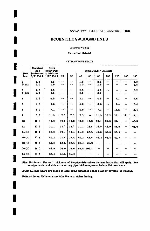
/ / /
I I /
Section T w o - F I E L D F A B R I C A T I O N 1 0 3
ECCENTRIC SWEDGED E N D S
Labor For Welding
Carbon Steel Material
NET MAN HOURS EACH
SCHEDULE NUMBERS Size Ins. 30 40 60 80 I00 120 140 160
2 - - 1.8 - - 2 .2 . . . . . . 3 .9 2 - 1 / 2 - - 2 .0 - - 2 .9 . . . . . . 4 .8
I 3 - - 2 .3 - - 3 .2 . . . . . . 5 .2 3 - I / 2 - - 2 .6 - - 3 .8 . . . . . . . .
I / I / I I /
Standard E x t r a Pipe Heavy Pipe
& OD Sizes & OD Sizes S/S"Th~k 1/2"Thtck ~-0
1.8 2 .2 - - 2 .0 2 .9 - -
2.3 3 .2 - - 2 .6 3 .8 - -
4 3.1 4 .5 . . . . 3 .1 - - 4 .5 - - 7 .1 - - 7 .6
I
5 4 . 0 6 . 0 . . . . 4 . 0 - - 6 . 0 - - 9 . 4 - - 1 0 . 4
6 4 . 9 7 . 1 . . . . 4 . 9 - - 7 . 1 - - 1 3 . 8 - - 1 4 . 4
8 7.3 11.9 7 .3 7 .3 7 .3 - - 11.9 20. 5 20. 1 22.1 24.1
10 10.0 16.2 10.0 10.0 10.0 16.2 20. 1 24.8 32.1 - - 45.8
12 13.7 21.1 13.7 13.7 21.1 25.6 32.9 43 .9 56.8 - - 64 .0
14 OD 19.4 30.2 19.4 19.4 31.0 37.5 45.8 58.6 80. 5 . . . .
16 OD 27.4 40. 2 27.4 27.4 40. 2 47.6 52.3 68.8 89.7 . . . .
18 OD 32.5 54.9 32.5 32.5 60. 4 85.2 . . . . . . . . . .
20 OD 36.0 62.9 36.0 36.0 68.8 100. 7 . . . . . . . . . .
24 OD 51.3 82.4 51.3 51.3 �9 .
P~pe T~clmess: The wall thickness of the pipe determines the man hours that will apply. For swedged ends on double extra strong pipe thickness, use schedule 160 man hours.
Ends: All man hours are based on ends being furnished either plain or beveled for welding.
thri l led ~ e s : Unlisted s izes take the next higher listing.
/

104 Section Two--FIELD FABRICATION
E N D C L O S U R E S - - P R E S S U R E T Y P E
Carbon Steel Material
Nora. Pipe Size Ins.
1-1/2
2 ~-1/2
3 s-l/~
10
12
14
16
18
20
24
Standard Pipe
& OD Sizes 3/8" Thick
0 .9
1 . 2 1 . 3
1.5 1.6
1 . 8
2 . 3
2 . 6
3.7
4 . 6
5.5
8 .6
7.4
9 .0
9 .7
1 0 . 6
NET MAN HOURS EACH
SCHEDULE NUMBERS Ext ra
Heavy Pipe F XX Hy. & OD Sizes or 1 /2" Thick 40 60 80 100 120 140 160
1.0 0 .9 - - 0 .9 . . . . . . 2 .3
1.3 1.2 - - 1.3 . . . . . . 3 .5 1.5 1.3 - - 1.5 . . . . . . 4 .3
1.8 1.5 - - 1.8 . . . . . . 4 .5 2.1 1.6 - - 2.1 . . . . . . . .
2 .4 1.8 - - 2 .4 - - 5.8 - - 6 .0
2 . 9 2 . 3 - - 2 . 9 - - 7 . 5 - - 7 . 9
3 . 3 2 . 8 - - 3 . 3 - - 9 . 3 - - 1 0 . 2
4 .7 3 .7 - - 4 .7 8 .9 12.5 14.8 15.8
5.9 4 .6 5.9 10. 3 12.7 21.4 23.0 24.7
7 . 2 6 . 7 7 . 7 1 3 . 0 1 8 . 9 2 8 . 6 31.2 3 3 . 7
8.8 8 .0 9 .9 15. I 20. 9 32.9 44.5 46.3
9 .7 9 .7 12.5 16.6 23.5 37.9 56.1 ~.8
11.3 13.9 16.2 21.8 29.6 42.8 67.6 71.3
12.5 16.8 19.8 27.0 35.8 47.8 79.1
14.9 19.6 23.5 32.2 42.1 52.2 - -
P~pe Th~clmess: WaLl th ickness of pipe d e t e r m i n e s the man hours that will apply. Fo r double s t rong pipe th ickness use schedule 160 man hours .
Construction: End c losu re s such as orange peel , saddle, or flat plate type.
Preheating:. If specif ied or r equ i red by codes, add for thls operat ion. See man hours for p r e - heating.
Stress Retlevin~. St r e s s re l ieving of welds in carbon s tee l ma t e r i a l is r equ i red by the A. S. A. Code for p r e s s u r e piping where the wall th ickness is 3 /4" o r g r e a t e r .
All s i ze s of butt welds shown below the ruled l ines a r e 3 /4" or g r e a t e r /nwal l th ickness and must be s t r e s s re l ieved, ff the end c losure involves a c i r cumfe ren t i a l weld. Where s t r e s s re l iev ing is requi red , an ex t ra charge should be made. See man hours for s t r e s s re l ieving.
Unlisted ~lzes: Unlisted s i zes take the next higher list/rig.
I I I I I I I
I I I I I I
I I I

/
I / /
Section Two-FIELD FABRICATION 105
H E A V Y W A L L E N D C L O S U R E S - - P R E S S U R E T Y P E
Carbon Steel Material NET MAN HOURS EACH
Nomin',d WALL THICKNESS IN.
/
I I I I / /
I / /
I
Pipe L Size .750 1.00 1.25
5.4 - - 3 4
5 6 8
10 12 14 16 18 20 22 24
10 12 14 16 18 20 22 24
20 22 24
8.1 9.9
15.8 16.6
9.6 11.6 18.5 19.5 26.3
2.75 3.00 3.25
47.7 66.1 66.6 88.5 98.8
106.6 117.2 127.8
44.6 61.8 62.3 82.8 92.4 99.7
109.6 119.5
69.1 69.7 92.6
103.4 111.5 122.7 133.8
4.75 5.00 5.25
142.5 156.8 171.1
147.5 162.4 177.1
152.7 168.0 183.4
1.50
10.9 13.1 21.0 22.1 29.9 41.3 47.7
3.50
1.75 2.00 2.25 2.50
14.8 23.7 24.9 33.7 46.7 53.9 62.8
25.8 27.1 ',~.8 51.0 58.8 68.4 76.2 82.2 90.5 98.8
27.4 28.8 39.1 54.0 62.3 72.6 80.8 87.2 95.9
104.7
30.8 41.8 57.8 66.7 77.5 86.4 93.2
102.5 111.9
3.75 4.00 4.25 4.50
79.8 105.7 117.9 127.2 140.1 152.7
6.00
166.9 183.6 200.4
132.3 145.6 158.8
72.2 72.9 76.2 96.8 101.1
108.0 112.8 116.6 121.8 128.3 1~.0 139.8 146.1
5.50 5.75
157.3 162.0 173.1 178.3 188.9 194.6
136.9 150.7 164.4
Construction: End closures as such are field fabricated closures; orange peel, ~ddle , or flat plate type.
Preheating." If specified or required by codes, add for this operation. See man hours for preheating.
Stress Relieving: Stress relieving of welds in carbon steel material is required by the A.S.A. Code of Pressure Piping where the wall thickness is :g4" or greater.
All the above butt welds are :g4" or greater and must be stress relieved, if end closure involves a circumferential weld.
See respective man hour tables for stress relieving.
I
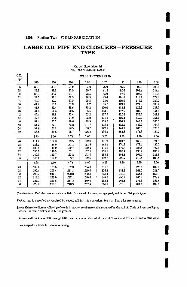
106 Section Two--FIELD FABRICATION
L A R G E O.D . P I P E E N D C I X ) S U R E S - - P R E S S U R E T Y P E
Carbon Steel Material NET MAN HOURS EACH
l / / /
O.D. Pipe In.
26 28 30 32 34 36 38 40 42 44 46 48 54 60
26 28 30 32 34 36
26 28 30 32 34 36
WALL THICKNESS IN.
.375 .500 .750 1.00 1.25
33.3 35.2 36.9 38.5 40.0 41.4 42.8 44.6 46.4 47.9 87.4 51.2 54.8 58.5
2.25
114.7 123.2 129.6 135.0 140.3 145.1
40.7 43.0 45.2 47.1 49.0 50.6 52.4 54.5 56.8 58.6 60.7 62.7 66.9 71.6
2.50
124.8 134.0 141.0 146.9 152.7 157.9
53.2 57.0 60.1 62.5 65.0 67.3 69.6 72.5 75.4 77.9 80.6 83.2 88.9 95.1
2.75
133.5 143.3 150.7 157.1 163.2 168.7
65.0 69.7 73.5 76.5 79.5 82.2 85.2 88.6 92.2 95.2 98.5
101.7 108.7 116.3
3.00
142.0 152.5 160.4 167.1 173.7 179.6
76.0 81.5 85.9 89.4 93.0 96.2
100.0 103.6 107.7 111.3 115.2 118.9 127.1 136.1
3.25
151.9 163.1 171.6 178.8 185.9 192.2
1.50 1.75
86.6 92.6 97.6
101.6 105.6 109.3 113.2 117.6 122.4 126.4 130.9 135.1 144.3 154.6
3.50
159.2 170.9 179.8 187.4 194.8 200.7
96.2 102.8 108.2 112.7 117.2 121.2 125.6 130.5 135.7 140.2 145.1 149.9 160.0 171.5
3.75
166.9 179.1 188.4 196.4 204.1 210.4
4.25 4,50 4.75 5.00 5.25 5.50 5.75
182.1 195.4 205.7 214.3 222.7 229.6
197.3 211.8 222.8 232.1 241.3 248.9
218.2 234.1 246.3 256.7 266.8 275.2
211.0 226.4 238.1 248.2 258.1 266.1
204.0 219.0 230.3 240.0 249.6 257.4
203.4 214.1 223.0 231.8 239.1
225.6 242.0 254.6 265.4 275.9 284.5
2oo l 105.6 113.4 119.3 124.3 / 129.2 133.7 138.5 144.0 / 149.6 154.6 160.1 165.3 176.5 / 189.2
4.00
174.9
187.7 I 197.5 205.8 213.9 220.5
232.0 248.7 261.7 272.8 / 283.6 292.5
Construction: End closures as such are field fabricated closures; orange peel, saddle, or flat plate type.
Preheating: If specified or required by codes, add for this operation. See man hours for preheating.
Stress Relieving: Stress relieving of welds in carbon steel material is required by the A.S.A. Code of Pressure Piping where the wall thickness is 3/4" or greater.
Above wall thickness .750 through 6.00 must be stress relieved, if the end closure involves a circumferential weld.
See respective table for stress relieving.
l l /
l /
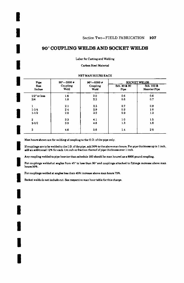
I I I /
I /
I I
Section Two--FIELD FABRICATION
90~ COUPLING WELDS AND SOCKET WELDS
Labor for Cutting and Welding
Carbon Steel Material
NET MAN HOURS EACH
107
Pipe 90~ # Size Coupling
Inches Weld
1/2" or less 1.6 3/4 1.8
1 2.1 1-1/4 2.4 1-1/2 2.6
2 3.3 2-1/2 3.9
3 4.6
90~ # Coupling Weld
2.0 2.2
2.5 2.9 3.2
4.1 4.8
5.6
SOCKET WELDS Sch. 40 & 80
Pipe
0.6 0.6
0.7 0.9 0.9
1.0 1.3
1.4
Sch. 100 & Heavier Pipe
0.6 0.7
0.8 1.0 1.2
1.5 1.6
2.0
I I I I I I I
Man hours shown are for welding ofcoupling to the O.D. ofthe pipe only.
If couplings are to be welded to the I.D. ofthe pipe, add 50% to the above man hours. For pipe thickness up to 1 inch, add an additional 12% for each 1/4 inch or fraction thereof ofpipe thickness over 1 inch.
Any coupling welded to pipe heavier than schedule 160 should be man houred as a 6000 pound coupling.
For couplings welded at angles from 45 ~ to less than 90 ~ and couplings attached to fittings increase above man hours 50%.
For couplings welded at angles less than 45% increase above man hours 75%.
Socket welds do not include cut. See respective man hour table for this charge.
I
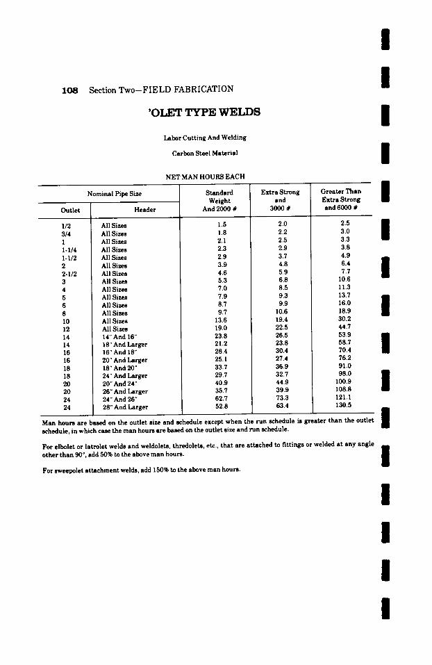
1 0 8 Section Two--FIELD FABRICATION
'OT.ET TYPE WELDS
Labor Cutting And Welding
Carbon Steel Material
NET MAN HOURS EACH
Outlet
1/2 3/4 I I-I/4 I-I/2 2 2-I/2 3 4 5 6 8 I0 12 14 14 16 16 18 18 20 20 24 24
Nominal Pipe Size
Header
All Sizes All Sizes All Sizes All Sizes All Sizes All Sizes All Sizes All Sizes All Sizes All Sizes All Sizes All Sizes All Sizes All Sizes 14'" And 16 ~ 18" And Larger 16" And 18" 20" And Larger 18" And 20" 24" And Larger 20" And 24" 26" And Larger 24" And 26" 28" And Larger
Standard Weight
And 2000 #
1.5 1.8 2.1 2.3 2.9 3.9 4.6 5.3 7.0 7.9 8.7 9.7
13.6 19.0 23.8 21.2 28.4 25.1 33.7 29.7 40.9 35.7 62.7 52.8
Extra Strong and
3000 #
2.0 2.2 2.5 2.9 3.7 4.8 5.9 6.8 8.5 9.3 9.9
10.6 19.4 22.5 26.5 23.8 30.4 27.4 36.9 32.7 44.9 39.9 73.3 63.4
Greater Than Extra Strong and 6000 #
/ / /
l l
3.0 3.3 3.8 4.9
6.4 i 7.7 10.6 11.3
13.7 I 16.0 18.9 30.2 44.7 53.9 / 58.7 70.4 76.2 91.0 98.0 /
100.9 108.8 121.1 130.5
Man hours are based on the outlet size and schedule except when the run schedule is greater than the outlet schedule, in which case the man hours are based on the outlet size and run schedule.
/ For elbolet or latrolet welds and weldolets, thredolets, etc., that are attached to fittings or welded at any angle i other than 90 ~ , add 50% to the above man hours. i For sweepolet attachment welds, add 150% to the above man hours.
l l I l
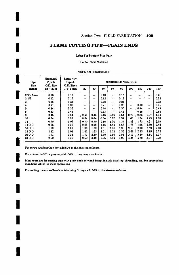
/
/ Section Two--FIELD FABRICATION 109
I
I
I Pipe Size
Inches / ' 2" OT L e ~ 2-1/2 3 4
6 8 10 12 14 O.D. 16 O.D. 18 O.D. 2 0 0 . D .
i 24 O.D.
F L A M E C U T T I N G P I P E - - P L A I N E N D S
Labor For S t r a i g h t Pipe Only
Ca rbon Steel Ma te r i a l
Standard Pipe&
O.D. Size 3/8" Thick
0.10 0.12 0.15 0.21 0.24 0.33 0.46 0.64 0.70 0.98 1.09 1.42 1.71 2.60
E x t r a Hvy.
Pipe & O.D. Sizes 1/2" Th ick
0.15 0.17 0.21 0.28 0.36 0.45 0.64 0.92 1.09 1.30 1.61 2.01 2.24 3.30
NET MAN HOURS EACH
SCHEDULE NUMBERS
20 30 40 60 80 100 120 140 160
. . . . 0.10 -- 0.15 . . . . . 0.21
. . . . 0.12 -- 0.17 . . . . . 0.23 - -- 0.15 -- 0.21 . . . . . . 0.28 -- - 0.21 -- 0.28 -- 0.38 -- 0.41 . . . . 0.24 -- 0.36 - 0.44 -- 0.49 -- - 0.33 -- 0.45 -- 0.56 -- 0.63
0.46 0.46 0.46 0.59 0.64 0.76 0.86 0.97 1.14 0.64 0.64 0.64 0.92 0.99 1.09 1.24 1.43 1.73 0.70 0.70 0.86 1.30 1.37 1.48 1.73 1.91 2.05 0.98 0.98 1.15 1.44 1.67 1.78 1.96 2.30 2.42 1.09 1.09 1.61 1.78 1.90 2.13 2.30 2.59 2.93 1.42 1.65 2.01 2.24 2.36 2.66 2.83 3.19 3.72 1.71 2.30 2.48 2.66 2.83 3.13 3.30 3.84 4.37 2.60 3.48 3.66 3.84 3.95 4.31 4.78 5.37 6.08
For m i t r e cu ts less t h a n 30 ~ , add 50% to the above m a n hours.
/
/
For mi t r e cu ts 30 ~ or g rea te r , add 100% to the above m a n hours.
Man hours a re for c u t t i n g pipe wi th p la in ends only and do not include bevel ing , t h r ead ing , etc. See app rop r i a t e m a n hour t ab le s for these opera t ions .
For cu t t i ng the ends of bends or t r i m m i n g f i t t ings , add 50% to the above m a n hours .
I /
I /
/

1 1 0 Section Two--FIELD FABRICATION
FLAME C ~ G HEAVY W~,TJ. PIPE--PL~W~I E N D S
Labor For S t ra igh t Pipe Only
Carbon Steel Mater ial
NET MAN HOURS EACH
I I I I
Nominal Pi~ Size
3 4 5 6 8 10 12 14 16 18 20 22 24
10 12 14 16 18 20 22 24
20 22 24
WALL THICKNESS IN INCHES I �9 750 1.00 1.25 1.50 1.75 2.00 2.25 2.50
0.53 0.94 . . . . . . . . . . . i
H 0.94 1.12 1.59 1.77 . . . . . . . . -- 1.30 1.65 2.00 2.24 2.54 . . . . -- 1.59 1.89 2.24 2.54 2.77 3.19 -- -- 1.89 2.24 2.48 2.89 3.13 3.48 4.07 . . . . 2.48 2.77 3.13 3.42 3.84 4.37
$ . . . . . . 3.13 3.36 3.84 4.25 4.78 . . . . . 3.60 3.72 4.13 4.60 5.25 . . . . . . . . 4.31 4.96 5.61 6.14 . . . . . . . . . 4.60 6.14 6.84
i
. . . . . . . . . . 6.14 6.84 7.73 i
$ . . . . . . . . . . . . . . 8.38 . . . . . . . . . . . . . 9.50
2.75 3.00 3.25 3.50 3.75 4.00 4.25 4.50
4.72 5.02 . . . . . . . . . . . . 5.31 5.72 6.14 6.61 . . . . . . . . 5.84 6.31 6.61 7.49 8.02 8.79 . . . . 6.67 7.20 7.73 8.38 9.09 9.97 . . . . 7.49 8.02 8.79 9.50 10.27 11.39 . . . . 8.26 8.91 9.79 10.68 11.56 12.57 13.63 14.63 9.26 10.03 10.68 11.86 12.92 13.92 14.99 16.11
10.27 11.15 12.10 13.22 13.92 15.46 16.87 18.47
4.75 5.00 5.25 5.50 5.75 6.00
17.70 18.64 19.77 20.77 19.35 20.41 21.54 22.72 22.30 23.60 24.78 26.14
15.64 16.58 17.23 18.35 19.94 21.00
For mitre cuts less than 30 ~ add 50~ to the above man hours.
For mitre cuts 30 ~ or greater , add 100% to the above man hours.
Man hours are for cut t ing pipe with plain ends only and do not include beveling, threading, etc. See appropriate man hour tables for these operations.
For cut t ing the ends ofbonds or t r imming fittings, add 50% to the above man hours.
I / / / / / /
I
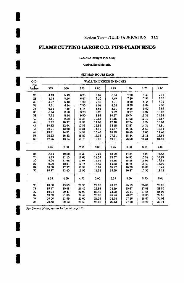
II II II II II II II II / /
I I / / /
Section Two-F IELD FABRICATION 111
FLAME C ~ G LARGE O.D. PIPE-PLAIN E N D S
Labor for Straight Pipe Only
Carbon Steel Material
NET MAN HOURS EACH
O . D .
Pipe Inches
26 28 30 32 34 36 38 40 42 44 46 48 54 60
26 28 30 32 34 36
26 28 30 32 34 36
.375
4.13 4.78 5.07 5.61 6.14 6.84 7.72 8.61 9.62
10.92 12.21 13.81 15.53 17.25
2.25
8.14 8.79 9.26 9.79
10.38 10.97
4.25
18.00 18.47 18.94 19.53 20.06 20.53
WALL THICKNESS IN INCHES
.500 .750 1.00 1.25 1.50 1.75 2.00
5.49 6.20 6.67 6.84 7.20 7.49 7.73 5.96 6.67 7.20 7.49 7.29 7.91 8.20 6.43 7.20 7.49 7.91 8.20 8.44 i 8.79 6.84 7.55 8.02 8.38 8.79 9.09 9.26 7.55 8.14 8.61 8.91 9.26 9.62 9.85 8.20 8.79 9.26 9.62 9.97 10.27 10.62 8.44 9.50 9.97 10.27 10.74 11.33 11.68 9.62 10.38 10.68 11.15 11.62 12.10 12.57
10.97 11.39 11.68 12.10 12.74 13.22 13.63 12.04 12.57 12.92 13.45 13.87 14.34 14.81 13.22 13.81 14.10 14.57 15.16 15.69 16.11 14.51 14.99 15.46 15.93 16.40 17.05 17.46 16.32 16.85 17.39 17.91 18.44 19.18 19.65 18.14 18.73 19.32 19.91 20.50 21.31 21.83
2.50 2.75 3.00 3.25 3.50 3.75 4.00
10.50 11.39 12.27 13.22 14.34 14.99 16.58 11.15 11.63 12.57 13.57 14.81 15.52 16.99 11.68 12.04 12.92 14.16 15.28 15.93 17.52 12.27 12.74 13.45 14.63 15.75 16.40 18.00 12.92 13.39 13.87 15.22 16.23 16.87 18.47 13.45 13.92 14.34 15.69 16.87 17.52 19.12
4.50 4.75 5.00 5.25 5.50 5.75 6.00
19.53 20.95 22.30 23.72 25.19 26.61 28.03 20.06 21.42 22.95 24.19 25.67 27.08 28.50 20.41 22.00 23.42 24.78 26.14 27.55 28.97 ! 21.00 22.48 23.90 25.25 26.67 I 28.03 29.50 21.59 23.00 24.37 25.78 j 27.26 28.67 30.09 22.13 23.60 25.00 26.43 27.73 29.21 30.74
For General Notes, see the bottom of page 110.
I

112 Section Two--FIELD FABRICATION
F L A M E BEVET,TNG PIPE F O R WET.PING
"V" Type Bevels
Labor for Straight Pipe Only
Carbon Steel Material
NET MAN HOURS EACH
I I I I I
Pipe S tanda rd Ex t ra Hvy.
Size Pipe & Pipe & S C H E D U L E N U M B E R S Inches O.D. Sizes O.D. Sizes
3/8" Thick I/2" Thick 20 30 40 60 80 I00 120 140 160
2"or less 0.08 0.12 . . . . 0.08 0.12 -- 0.16 2-I /2" 0.09 0.14 . . . . 0.09 0.14 : -- 0.18
3 0.12 0.16 -- - 0.12 - 0.16 . . . . . . 0.22
4 0.16 0.22 . . . . 0.16 -- 0.22 -- 0.30 -- 0.32
5 0.20 0.28 . . . . 0.20 -- 0.28 -- 0.35 -- 0.39
6 0.26 0.35 . . . . 0.26 -- 0.35 -- 0.45 -- 0.49
8 0.37 0.51 0.37 0.37 0.37 0.46 0.51 0.60 0.68 0.75 --
I0 0.51 0.72 0.51 0.51 0.51 0.72 0.78 0.86 0.95
12 0.55 0.86 0.55 0.55 0.68 1.02 1.08 1.18 . . . . . .
14 O.D. 0.57 1.02 0.77 0.77 0.91 1.13 1.31 . . . . . . . .
16 O.D. 0.86 1.27 0.86 0.86 1.27 1.40 1.55 . . . . . . . .
18 O.D. 1.11 1.58 I. 11 1.30 1.58 1.77 . . . . . . . . . .
20 O.D. 1.35 1.77 1.35 1.82 1.95 2.15 . . . . . . . . . .
24 O.D. 2.04 2.60 2.04 2.74 2.88 . . . . . . . . . . . .
For mi t re bevels add 50% to the above man hours.
Above m a n hours are for f lame "V" beveling only and do not include cut t ing or in terna l machining. See respective man hour tables for these charges.
For bevel ing on the ends of bends or shop t r immed fit t ings, add 50% to the above man hours.
I / /
I /
I /
I / / /

/ /
I / / /
l / / / /
Section Two--FIELD FABRICATION 113
FLAME BEVET.TNG LARGE O.D. PIPE FOR WET.PING
Labor For Straight Pipe Only
Carbon Steel Material
NET MAN HOURS EACH
O. D. Pipe Size
Inches
26
28
30
32
34
36
38
40
42
44
46
48
54
60
WALL THICKNESS IN INCHES
.375
3.27
3.75
4.00
4.43
4.84
5.39
6.10
6.80
7.59
8.59
9.63
10.89
12.25
13.62
.5OO
4.31
4.68
5.05
5.39
5.95
6.47
7.17
7.85
8.66
9.48
10.41
11.45
12.87
14.31
.750
4.87
5.24
5.69
5.95
6.43
6.91
7.47
8.18
8.96
9.89
10.89
11.82
13.31
14.79
I I
For Mitre Bevels add 50% to the above man hours.
Above man hours are for flame "V" beveling only and do not include cutting or internal machining. See respective man hour tables for these charges.
For beveling on the ends of bends or shop trimmed fittings, add 50% to the above man hours.
I l l

/
1 1 4 Section Two-FIELD FABRICATION /
THREADING PIPE- - INCLUDING CUT I Labor For Cut and Thread Only
Carbon Steel Material I NET MAN HOURS EACH
Pipe Size
Inches
2" or Less 2-I/2"
Standard Pipe&
O.D. Sizes 3/8"Thick
0.20 0.27
0.30
0.42
0.54
0.70
0.97
Extra Hvy. Pipe&
O.D. Sizes I/2"Thick
0.30 0.40
SCHEDULE NUMBERS /
20 30 40 60 80 100 120 140 160
. . . . 0.20 -- 0.30 . . . . . 0.42
. . . . 0.27 -- 0.40 . . . . . . 0.47
0.42 -- - 0.30 -- 0.42 -- 0.58 I
0.58 . . . . 0.42 -- 0.58 -- 0.84 -- 0.90
0.78 . . . . 0.54 -- 0.78 -- 0.91
10
12
14 O.D.
16 O.D.
18 O.D.
20 O.D.
24 O.D.
1.38
1.53
2.07
2.37
2.95
3.54
5.18
0.93 . . . . 0.70 -- 0.93 -- 1.18
1.07 /
1.35
1.35 0.97 0.97 0.97 1.26 1.35 1.64 1.83 2.04 2.38
1.84 1.38 1.38 1.38 1.84 2.11 2.44 2.58 3.08 3.65 i
2.44 1.53 1.53 2.07 2.75 2.90 3.17 3.65 4.14 4.38
2.67 2.07 2.07 2.67 2.95 3.39 3.85 4.14
3.45 2.37 2.37 3.45 3.71 4.14 4.38 4.87
4.14 2.95 3.65 4.14 4.38 4.87 5.42
4.72 3.54 4.72 5.68 6.16 6.49
6.89 5.18 7.23 7.67 7.93 8.37
Above man hours are for die cut IPS pipe threads only.
For threading the ends of bends, add 100% to the above man hours.
I /
I / / / /

I I
Sec t ion T w o - - F I E L D F A B R I C A T I O N 1 1 5
I I I I I
V ~ E L D E D C A R B O N S T E E L A T r A C H M E N T S
NET MAN HOURS ]PER LINEAL FOOT
Thickness of Pla te
E t c . , Inches
1/2 or l ess 3 / 4
1 i-I/4 1-1/2 i-3/4
Layout & Flame Cutting Pe r Lineal Inch
....... O. 05
....... 0.05
0. 05 �9 �9 , �9 �9 �9 �9
. . . . . . . 0. 07
. . . . . . . 0. 07
. . . . . . . 0. 08
O. 09
Fil le t Welding P e r
Lineal Inch
...... O. 05
...... O. 07
. . . . . . O. 09
. . . . . . 0 .10
. . . . . . 0 .10
. . . . . . 0 .20
0.20
Figure labor on bas is of total l ineal inches to be cut and fillet welded.
Unlisted thickness take the next higher listing.
I Any machining of bases , anchors , supports , lugs, e t c . , should be charged as an extra .
If preheating is required, add 100% to the above man hours.
I I I I I I I I

1 1 6 Sec t ion T w o - - F I E L D F A B R I C A T I O N
DRTTJJNG HOT,ES IN ~rET.T~~ A T r A ~
Carbon Steel Material
NET MAN HOURS EACH
/
I / /
Thickness of Plates, Angles, Etc. in Inches
1/2" or less 3/4
1 1-1/4 1-1/2 1-3/4
2 2-1/2
3 3-1/2
HOLE SIZE
3/4" and smaller
0.24 0.29
0.31 0.40 0.49 0.55
0.71 0.82
0.91 1.01
1.21
7/8", 1" and I-I/8"
0.29 0.34
0.40 0.49 0.55 0.71
0.82 0.91
1.12 1.21
1.42
I-I/4", I-I/2
0.34 0.43
0.49 0.55 0.71 0.86
1.00 1.12
1.32 1.52
1.73
"and2" 2-I/4" and 2-I/2"
0.47 0.64
0.67 0.71 0.91 1.12
1.32 1.62
I / /
1.82 I 2.14
2.44
I Unlisted thickness of plate or size ofholes take the next higher listing.
If holes are to be tapped--Add 33-1/3%.
Drilling ofsentinel safety or tell tale holes should be charged at .05 man hours each net. n
m The above man hours are for drilling holes in fiat carbon steel plate and structural shapes only.
For drilling holes in pipe or other contoured objects, perpendicular to contoured surface, add 100% to above man
hours. I
For drilling holes in pipe or other contoured objects, oblique to contoured surface, add 175% to above man hours.
I I I I I
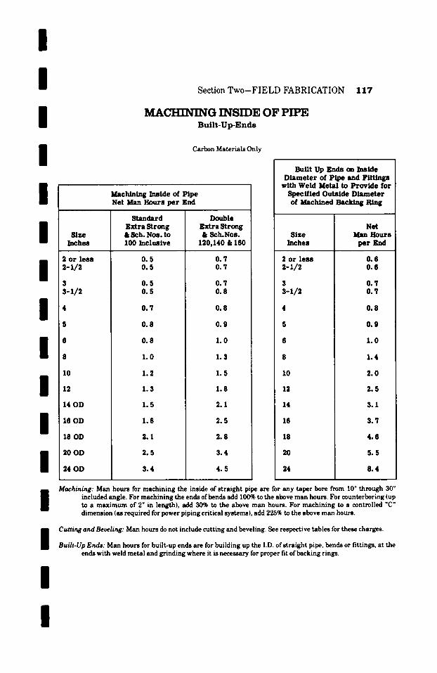
/ / / / / / / / / / /
I
Sect ion T w o - F I E L D F A B R I C A T I O N 1 1 7
M A ~ G INSIDE OF PIPE B u i l t - U p - E n d s
Carbon Materials Only
Size Inches
2 or less 2-1/2
3 s-1/2
10
12
14 OD
16 OD
18 OD
20 OD
2 4 0 D
Machining Inside of Pipe Net Man Hours per grid
Standard Extra Strong & Sch. Noe. to 100/nchmive
0.5 0.5
0.5 0.5
0.7
0.8
0 .8
1.0
1.2
1 .3
1.5
1.8
2.1
2 .5
3 .4
Double Extra S t rm~ & 8ch.Nos.
120,140 & 160
0.7 0.7
0.7 0.8
0 .8
0.9
1.0
1.3
1.5
1.8
2.1
2.5
2.8
3 .4
4.5
Built Up Ends ms Inside Diameter of Pipe and Fittings
with Weld Metal to Provide for Specified Outside Diameter of Machined Backing Ring
Size Inches
2 or leas 2-1/~
3 3-1/2
Net Man Hours
pe r Knd
0.6 0.6
0.7 0.7
10
12
14
16
18
20
24
0 .8
0 .9
1.0
1.4
2 .0
2.5
3.1
3.7
4 .6
5 .5
8 .4
Machining: Man hours for machining the inside of straight pipe are for any taper bore from 10 ~ through 30 ~ included angle. For machining the ends ofbends add 100% to the above man hours. For counterboring (up to a maximum of 2" in length), add 30% to the above man hours. For machining to a controlled "C" dimension (as required for power piping critical systems), add 225q~ to the above man hours.
I /
Cutting and Beveling: Man hours do not include cutting and beveling. See respective tables for these charges.
Built-Up Ends: Man hours for built-up ends are for building up the I.D. of straight pipe, bends or fittings, at the ends with weld metal and grinding where it is necessary for proper fit of backing rings.
/
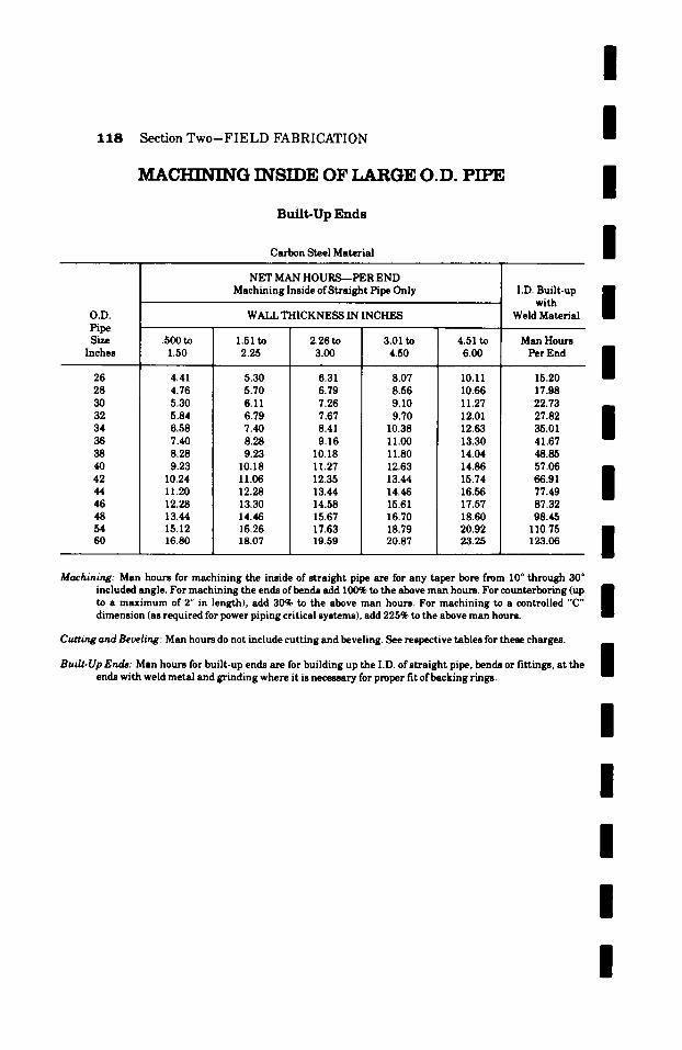
1 1 8 S e c t i o n T w o - - F I E L D F A B R I C A T I O N
MACHINING INSIDE OF LARGE O.D. PIPE
B u i l t - U p E n d s
Carbon Steel Material
/ /
I /
O.V. Pipe Size
Inches
26 28 30 32 34 36 38 40 42 44 46 48 54 60
NET MAN HOURS--PER END Machining Inside of Straight Pipe Only
WALL THICKNESS IN INCHES
.500 to 1.50
4.41 4.76 5.30 5.84 6.58 7.40 8.28 9.23
10.24 11.20 12.28 13.44 15.12 16.80
1.51 to 2.25
5.30 5.70 6.11 6.79 7.40 8.28 9.23
10.18 11.06 12.28 13.30 14.46 16.26 18.07
2.26 to 3.00
6.31 6.79 7.26 7.67 8.41 9.16
10.18 11.27 12.35 13.44 14.58 15.67 17.63 19.59
3.01 to 4.50
8.07 8.56 9.10 9.70
10.38 11.00 11.80 12.63 13.44 14.46 15.61 16.70 18.79 20.87
4.51 to 6.00
10.11 10.66 11.27 12.01 12.63 13.30 14.04 14.86 15.74 16.56 17.57 18.60 20.92 23.25
I.D. Built-up with
Weld Material
Man Hours Per End
15.20 17.98 22.73 27.82 35.01 41.67 48.85 57.06 66.91 77.49 87.32 98.45
110.75 123.06
N N I I I
Machining: Man hours for machining the inside of straight pipe are for any taper bore from 10 ~ through 30 ~ included angle. For machining the ends of bends add 100% to the above man hours. For counterboring (up n to a maximum of 2" in length), add 30% to the above man hours. For machining to a controlled "C" | dimension (as required for power piping critical systems), add 225% to the above man hours.
Cutting and Beveling: Man hours do not include cutting and beveling. See respective tables for these charges.
Built-Up Ends: Man hours for built-up ends are for building up the I.D. of straight pipe, bends or fittings, at the ends with weld metal and grinding where it is neces~____ry for proper fit of backing rings.
/
I /
I / /
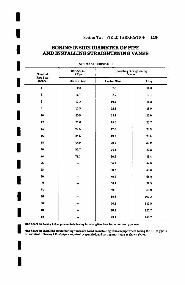
I I I I
Section Two-FIELD FABRICATION
BORING INSIDE DIAMETER OF PIPE A N D INST~T.T.TNG STRAIGI~T~:NING VANES
NET MAN HOURS EACH
Boring I.D. Installing Straightening
1 1 9
I m 5
6
I I I I
Nominal Pipe Size Inches
12
14
18
20
24
26
28
30
32
I I
34
36
38
40
42
of Pipe
Carbon Steel
9.8
11.7
13.3
17.5
20.9
25.6
29.5
35.5
44.0
57.7
79.1
Carbon Steel
7.6
8.7
10.7
12.6
13.9
15.6
17.6
19.5
22.1
24.8
30.2
35.9
39.6
45.9
53.1
59.8
68.8
76.9
85.2
93.7
Vanes
Alloy
11.3
13.1
15.2
18.9
20.9
23.7
26.3
29.5
33.0
37.2
45.4
54.0
59.8
68.8
79.9
89.9
103.3
115.8
127.7
140.7
Man hours for boring I.D. of pipe include boring for a length of four times nominal pipe size.
Man hours for L, mt~ling straightening vanes are based on installing vanes in pipe where boring the I.D. of pipe is not required. If boring I.D. ofpipe is required or specified, add boring man hours as shown above.
/
/
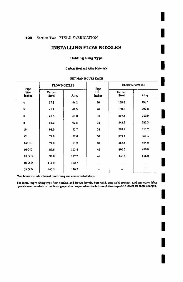
/
1 2 0 Section Two--FIELD FABRICATION
I N S T A I J . M ~ G F L O W N O Z Z L E S
Holding Ring Type
Carbon Steel and Alloy Materials
NET MAN HOURS EACH
I /
I /
Pipe Size
Inches
10
12
140.D.
16 O.D.
18 O.D.
20 O.D.
24 O.D.
FLOW NOZZLES
Carbon Steel
37.8
41.1
45.8
55.2
63.0
71.0
77.6
87.6
98.8
111.0
140.3
Alloy
44.2
47.3
53.0
62.5
72.7
82.6
91.2
103.4
117.2
133.7
170.7
Pipe O.D.
Inches
26
28
30
32
FLOW NOZZLES
Carbon Steel
165.6
189.6
217.4
248.5
Alloy
198.7
222.0
249.9
282.3
34
36
38
40
42
283.7
319.1
357.5
400.5
448.5
316.2
357.4
/
/
/
456.5
516.0
/ n
Man hours include internal machining and nozzle installation. B
m For installing welding type flow nozzles, add for the bevels, butt weld, butt weld preheat, and any other labor operation or non-destructive testing operation required for the butt weld. See respective tables for these charges.
/
/ / /
/
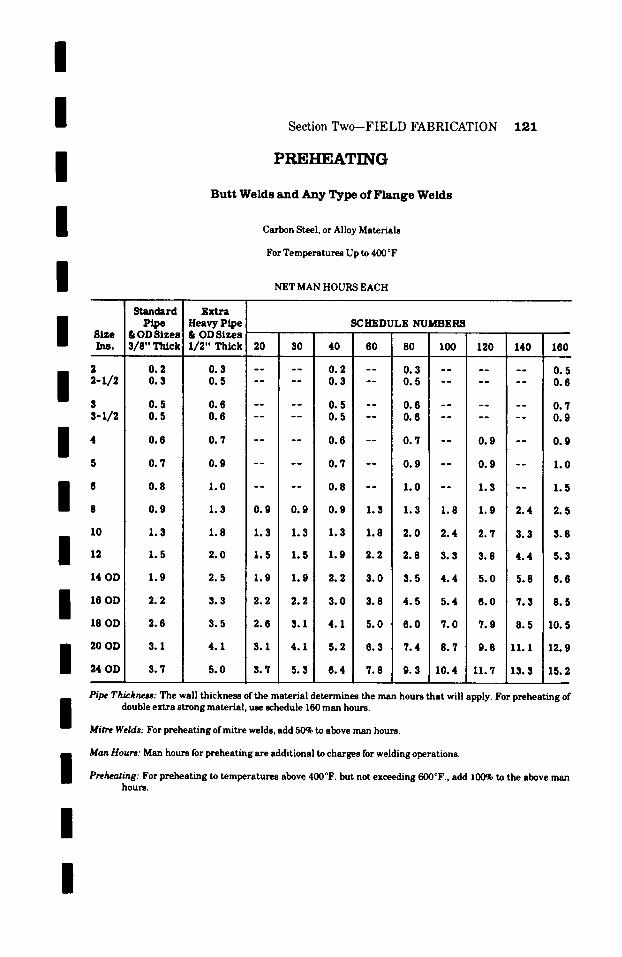
/
/ / /
/
Section Two--FIELD FABRICATION
PREHEATING
B u t t W e l d s a n d A n y T y p e o f F l a n g e W e l d s
Carbon Steel, or Alloy Materials
For Temperatures Up to 4(X)~
NET MAN HOURS EACH
1 2 1
81ze Ins.
2
I 2-x/2 s s-x/2
m 4
8
I , 10
14 OD
16 OD
18 OD
20 OD
24 OD
Standard
& OD Sizes 3/8" Thick
0 .2 0 .3
0 .5 0 .5
0 .6
0 .7
0 .8
0 .9
1.3
1 .5
1.9
2 .2
2 .6
3 .1
3 .7
Extra Heavy Pipe & OD Sizes i/2-Thick
SCHEDULE NUMBERS
20 30 40 60 80 100 120 140 160
0.3 . . . . 0.2 - - 0.3 . . . . . . 0.5 0.5 . . . . 0.3 - - 0.5 . . . . . . 0.6
0 .6 . . . . 0 .5 - - 0 .6 . . . . . . 0 .7 0 .6 . . . . 0 .5 - - 0 .6 . . . . . . 0 .9
0 . 7 . . . . 0 .6 - - 0 .7 - - 0 .9 - - 0 . 9
0 .9 . . . . 0 .7 - - 0 .9 - - 0 .9 - - 1 .0
1 .0 . . . . 0 .8 - - 1 .0 - - 1 .3 - - 1 .5
1 .3 0 .9 0 .9 0 .9 1.3 1 .3 1 .8 1 .9 2 .4 2 .5
1 .8 1 .3 1 .3 1 .3 1 .8 2 .0 2 .4 2 .7 3.3 3.8
2.0 1.5 1.5 1.9 2.2 2.8 3.3 3.8 4.4 5.3
2.5 1.9 1.9 2.2 3.0 3.5 4.4 5.0 5.8 6.6
3.3 2.2 2.2 3.0 3.8 4.5 5.4 6.0 7.3 8.5
3 .5 2 .6 3.1 4 .1 5 .0 6 . 0 7 .0 7 . 9 8 .5 10.5
4 .1 3 .1 4 .1 5 .2 6 .3 7 .4 8 .7 9 .8 11.1 12.9
5 .0 3 .7 5 .3 6 .4 7 .8 9 .3 10.4 11 .7 13.3 15.2
/ Pipe Thickness: The wall thickness of the material determines the man hours that will apply. For preheating of double extra strong material, use schedule 160 man hours.
Mitre Welds: For preheating of mitre welds, add 50~ to above man hours.
i Man Hours: Man hours for preheating are additional to charges for welding operations.
Preheating: For preheating to temperatures above 400~ but not exceeding 600~ add 10(~ to the above man hours.
/
I
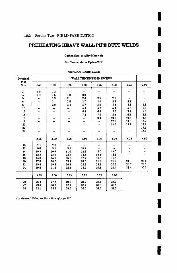
/
12~ Section Two-FIELD FABRICATION
P R E H E A T I N G H E A V Y W~T J, PIPE BIH'r ~]ET.YJS
Carbon Steel or Alloy M a t e r i a l s
For T e m p e r a t u r e s Up to 400~
N E T MAN H O U R S E A C H
Nominal t-ipe
Size
3 4 5 6 8 10 12 14 16 18 20 22 24
10 12 1 4
16 1 8
20 22 24
20 22 24
.750 1.00
1.0 1.2 1.4 1.5 -- 1.9 -- 2.1 -- 3.0 . . . .
. . . .
. .
. .
. . . .
. . . .
. .
2.75 3.00
7.1 7.6 8.6 i 9.1
10.3 10.9 12.3 13.0 14.8 15.8 17.0 18.2 18.4 19.8 19.8 21.2
4.75 5.00
26.4 27.7 29.3 30.7 32.1 33.7
W A L L T H I C K N E S S IN I N C H E S
1.25 1.50 1.75 2.00 2.25 2.50
I
I
I
I . . . . . . . . . . m
1.8 2.0 . . . . . . 2.1 2.4 2.5 2.8 . . . . 2.5 2.7 3.0 3.2 3.4 -- 3.4 3.7 3.9 4.4 4.5 4.8 4.1 4.4 4.7 5.4 5.8 6.3
| -- 6.1 6.6 7.0 7.4 8.0 - 7.3 7.9 8.4 9.1 9.6 - -- 9.4 10.0 1 0 . 5 1 1 . 6
. . . . . 12.3 13.0 13.7
. . . . 14.0 15.1 15.9
| . . . . . . . . 17.2 . . . . . . . . . 18.6
3.25 3.50 3.75 4.00 4.25 4.50
9.8 10.4 . . . . . . 11.6 12.3 13.0 14.0 - - 13.7 14.6 15.d 16.6 -- - 16.8 17.7 18.8 19.8 - -- 19.4 20.5 21.8 22.9 24.0 25.1 20.9 22.3 23.8 25.3 26.6 28.0 22.8 24.2 25.8 27.7 28.4 30.2
5.25 5.50 5.75 6.00
29.3 30.7 32.1 33.7 32.1 33.7 35.0 36.5 34.5 36.5 38.0 39.5
For General Notes, see the bottom @page 121.
I
I
I
I
I
I
I
I
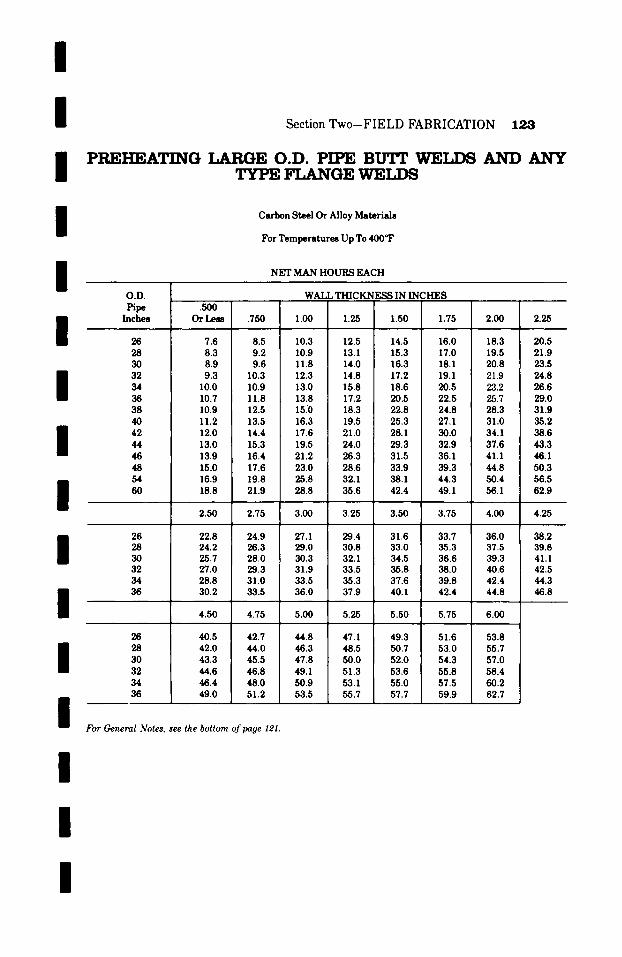
/
/ Section Two-FIELD FABRICATION 123
i PREHEATING LARGE O.D. PIPE BTTIT WELDS A N D A N Y TYPE FLANGE ~T]i~T,T")S
/
i
Carbon Steel Or Alloy Materials
For Temperatures Up To 400 OF
NET MAN HOURS EACH
/
/
I
I 1 / /
/
i
O.D. Pipe
Inches
26 28 30 32 34 36 38 40 42 44 46 48 54 60
26 28 30 32 34 36
26 28 30 32 34 36
WALL THICKNESS IN INCHES .5OO ~ I
Or Less .750 1.00 1.25 1.50 1.75 2.00 2.25
7.6 8.5 10.3 12.5 14.5 16.0 18.3 20.5 8.3 9.2 10.9 13.1 15.3 17.0 19.5 21.9 8.9 9.6 11.8 14.0 16.3 18.1 20.8 23.5 9.3 10.3 12.3 14.8 17.2 19.1 21.9 24.8
10.0 10.9 13.0 15.8 18.6 20.5 23.2 26.6 10.7 11.8 13.8 17.2 20.5 22.5 25.7 29.0 10.9 12.5 15.0 18.3 22.8 24.8 28.3 31.9 11.2 13.5 16.3 19.5 25.3 27.1 31.0 35.2 12.0 14.4 17.6 21.0 28.1 30.0 34.1 38.6 13.0 15.3 19.5 24.0 29.3 32.9 37.6 43.3 13.9 16.4 21.2 26.3 31.5 36.1 41.1 46.1 15.0 17.6 23.0 28.6 33.9 39.3 44.8 50.3 16.9 19.8 25.8 32.1 38.1 44.3 50.4 56.5 18.8 21.9 28.8 35.6 42.4 49.1 56.1 62.9
2.50 2.75 3.00 3.25 , 3.50 3.75 4.00 4.25
22.8 24.9 27.1 29.4 31.6 33.7 36.0 38.2 24.2 26.3 29.0 30.8 33.0 35.3 37.5 39.8 25.7 28.0 30.3 32.1 34.5 36.6 39.3 41.1 27.0 29.3 31.9 33.5 35.8 38.0 40.6 42.5 28.8 31.0 33.5 35.3 37.6 39.8 42.4 44.3 30.2 33.5 36.0 37.9 40.1 42.4 44.8 46.8
4.50 4.75 5.00 5.25 5.50 5.75 6.00
40.5 42.7 44.8 47.1 49.3 51.6 53.8 42.0 44.0 46.3 48.5 50.7 53.0 55.7 43.3 45.5 47.8 50.0 52.0 54.3 57.0 44.6 46.8 49.1 51.3 53.6 55.8 58.4 46.4 48.0 50.9 53.1 55.0 57.5 60.2 49.0 51.2 53.5 55.7 57.7 59.9 62.7
For C, eneml .Votes, see the bottom of page 121.
I
I

/
1 2 4 S e c t i o n T w o - - F I E L D F A B R I C A T I O N
P R E H E A T I N G 9 0 ~ N O Z Z L E W E L D S
Carbon Steel, or Alloy Materials
For Temperatures Up To 400~F
NET MAN HOURS EACH
S i z e Ins.
~-1/2 3 3-1/2
10
12
14 OD
16 OD
18 OD
20 OD
24 OD
S t a n d a r d P i p e
& OD S i z e s 3/8" Thick
0 . 5 0 . 6
0 . 6 0 . 7
0 . 9
1 . 0
1 . 3
1 .8
2 . 0
2 . 5
3 . 0
3 . 4
4 . 2
5 . 0
8 . 0
E x t r a Heavy P i p e & OD S i z e s 1 / 2 " T h i c k
S C H E D U L E N U M B E R S
20 30 40 60 80 100 120 140 160
0 . 6 . . . . 0 . 5 - - 0 . 6 . . . . . . 0 . 7 0 . 7 . . . . 0 . 6 - - 0 . 7 . . . . . . 0 . 9
0 . 9 . . . . 0 . 6 - - 0 . 9 . . . . . . 1 . 0 0 . 9 . . . . 0 . 7 - - 0 . 9 . . . . . . . .
1 . 0 . . . . 0 . 9 1 . 0 - - 1 . 4 - - 1 . 7
/ /
/
/
/
/ 1 .4 . . . . 1 . 0 1 . 4 - - 1 . 7 - - 1 . 8 i
g 1 . 8 [ - - 1 . 3 i - - 1 . 8 - - 2 . 0 - - 2 . 4
2 . 1 1 . 7 1 . 7 1 . 7 2 . 0 2 . 1 2 . 7 3 . 1 3 . 5 4 . 1
2 . 7 2 . 0 2 . 0 2 . 0 2 . 7 3 . 1 3 . 8 4 . 5 - - 5 . 9
3.3 2.5 2.5 2.8 3.5 4.5 5.2 6.0 - - 8.3
3 . 8 3 . 0 3 . 0 3 . 5 ! 4 . 6 5 . 9 6 . 6 7 . 8 - - 1 0 . 5
4 . 6 3 . 4 3 . 4 4 . 6 5 . 9 7 . 2 8 . 5 9 . 8 - - 1 3 . 7
5 . 5 4 . 2 4 . 8 6 . 3 7 . 9 9 . 6 1 0 . 5 1 2 . 7 - - 1 7 . 0
6 . 5 5 . 0 6 . 5 8 . 3 1 0 . 1 1 1 . 8 1 3 . 7 1 5 . 6 - -
7 . 8 6 . 0 8 . 5 1 0 . 3 1 2 . 5 15 .1 1 6 . 5 1 8 . 9 - -
Pipe Thickness: The size of the nozzle and the wall thickness of the header or nozzle (whichever is greater) determines the man hours to be used. For preheating of double extra strong thickness use schedule 160 man hours.
I /
/
/ i
Time: For reinforced 90 ~ nozzle welds, add 100% to the above man hours. 1 For 45~ nozzle welds, add 50% to the above man hours. l For reinforced 45 ~ nozzle welds, add 150% to the above man hours. For preheat ing to tempera tures above 400~F. but not exceeding 600~F., add 100% to the above man hours. Prehea t ing of coupling, weldolet, threadolet or socket welds should be charged at the same man hours as mm shown for the same size and schedule nozzle. 1 Man hours for preheat ing are additional to man hours for welding operations.
/
I

/
/ / /
Section Two-FIELD FABRICATION 125
P R E H E A T I N G L A R G E O.D. 9 0 ~ N O Z Z L E ~TETJ')6
Carbon Steel or Alloy Materials
For Temperatures Up To 400~
NET MAN HOURS EACH
/
/ / /
/ / /
O.V. Pipe Sizes
26 28 30 32 34 36 38 40 42 48 54 60
.5O0 .750
9.7 10.7 10.3 11.4 10.9 12.2 11.6 12.9 12.6 13.8 13.5 14.8 14.3 15.8 15.3 17.0 16.2 18.1 18.5 20.7 20.8 23.2 23.1 25.8
WALL THICKNESS IN INCHF~
1.00 1.25 1.50 1.75 2.00 2.25
12.9 15.6 18.3 20.1 23.0 25.8 13.8 16.6 19.2 21.2 24.4 27.7 14.8 17.6 20.5 22.8 26.1 29.5 15.5 18.5 21.6 24.0 27.5 31.0 16.3 19.9 23.2 25.7 29.3 33.4 17.5 21.6 25.7 28.2 32.2 36.5 18.9 23.0 28.6 31.0 35.5 40.1 20.2 24.5 31.7 34.2 39.1 44.1 21.8 26.3 34.0 37.8 43.0 48.5 24.9 30.1 38.8 43.2 49.1 55.5 28.1 33.9 43.7 48.5 55.2 62.3 31.2 37.6 48.5 53.9 61.4 69.3
Pipe Thickness: The size of the nozzle and the wall thickness determines the man hours to be used. For preheating of man hours.
of the header or nozzle (whichever is greater) double extra strong thickness use schedule 160
Time- For reinforced 90 ~ nozzle welds, add 100% to the above man hours. For 45 ~ nozzle welds, add 50% to the above man hours. For reinforced 45 o nozzle welds, add 150% to the above man hours. For preheating to temperatures above 400~ but not exceeding 600~ add 100% to the above man hours. Preheating of coupling, weldolet, threadolet or socket welds should be charged at the same man hours as shown for the same size and schedule nozzle. Man hours for preheating are additional to man hours for welding operations.
/
/
/
l /
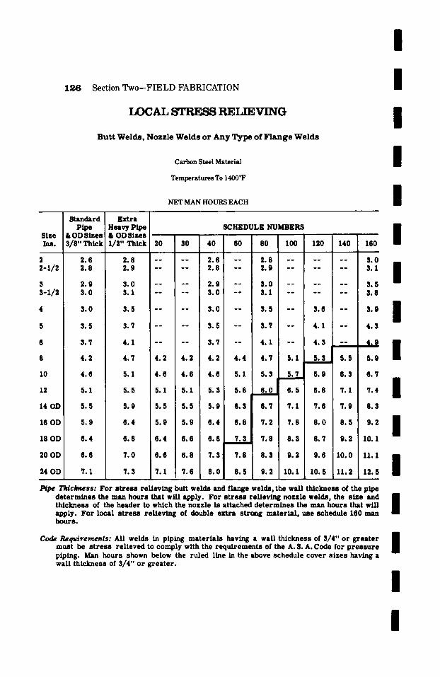
I
1 2 6 Section T w o - F I E L D F A B R I C A T I O N
IDCAL STRESS REI.T~.VING
B u t t W e l d s , N o z z l e W e l d s o r A n y T y p e o f F l a n g e W e l d s
Carbon Steel Material
Temperatures To 1400~
D l g O
Ins.
2 2-1/2 $ 3-1/2
8
10
12
14 OD
16 OD
18 OD
20 OD
24 OD
NET MAN HOURS EACH
/ / / /
Standard Ex t ra Pipe Heavy Pipe SCHEDULE NUMBEI~ /
4B t J U O L Z O 5 I U ~ O I F . ~ m ~
3 / 8 " Th ick 1 /2 " Th ick 20 30 40 60 80 100 120 140 160
2 .6 2 .8 . . . . 2 .6 - - 2 .8 . . . . . . 3 . 0 2 .8 2 .9 . . . . 2 .8 - - 2 .9 . . . . . . 3 .1
2 .9 ! 3.0 . . . . 2 .9 - - 3 .0 . . . . . . 3.5 3.0 3.1 . . . . 3 .0 - - 3.1 . . . . . . 3 .8
3 .0 3 .5 . . . . 3 .0 - - 3 .5 - - 3 .6 3 .9
3 .5 3 .7 . . . . 3 .5 - - 3 .7 - - 4 .1 4 . 3
3.7 4.1 . . . . 3.7 - - 4.1 - - 4.3 - ~ . ~ . . . . . . . ~
5.1 5.3 4.2 4 .7 4 .2 4 .2 4 .2 4 .4 4 .7
4 .6 5 .1 4 . 6 4 . 6 4 . 6 5 .1 5 .3 ! 5 .7 5 .9 6 .3 6 . 7
/ / /
Z i / 5.1 5.5 5.1 5.1 5.3 5.8 6 .8 7.1 7 .4
5 .5 5.9 5 .5 5 .5 5 .9 6 .3 6 .7 7.1 7 .6 7 .9 8 .3
5.9 6 .4 5 .9 5 .9 6 . 4 6 .8 7 .2 7 .8 8 . 0 8 . 5 9 .2
6.4 6.8 I 6 .4 6 .6 6 .8 7 .3 7 .8 8 .3 8 .7 9 .2 10.1
6.6 7.0 ! 6.6 6.8 7.3 7.8 I 8.3 9.2 9.6 I 0 . 0 I I . I
' / .1 7 .3 7. I 7 .6 8 . 0 8 . 5 i 9 .2 10.1 10.5 11.2 12.5
I
I I~pe T I d c ~ s s : For s t r e s s relieving butt welds and flange welds, the wall thickness of the pipe
determines the man hours that will apply. For s t r e s s relieving nozzle welds, the size and thickness of the header to wMch the nozzle is attached determines the man hours that will S apply. For local s t r e s s relieving of double extra stroag material , use schedule 160 man hours.
Code Requirements: All welds in piping mater ials having a wall thickness of 3/4" or greater B must be s t r e s s relieved to comply with the requirements of the A. S. A. Code for p res su re S piping. Man hours shown below the ruled llne in the above schedule cover s izes having a wall thickness of 3/4" or greater .
I
I
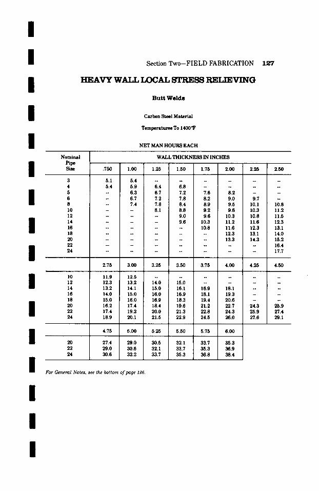
/
I I / /
Section Two-FIELD FABRICATION
HEAVY W.AT.T.I.XX~AL STRESS RETIRVING
Butt Welds
Carbon Steel Ma te r i a l
T e m p e r a t u r e s To 1400~
N E T M A N HOURS E A C H
127
I
I / / / /
I
I / /
N o m i n a l Pipe Siffie
3 4 5 6 8
10 12 14 16 18
20 22 24
10 12 14 16 18
20 22 24
20 22 24
W A L L T H I C K ~ IN I N C H E S
�9 750 1.00 1.25 1.50 1.75 2.00 2.25 2.50
5.1 5.4 . . . . . . 5.4 5.9 6.4 6.8 . . . . - 6.3 6.7 7.2 7.6 8.2 - -
- 6.7 7.2 7.8 8.2 9.0 9.7 -
- 7 . 4 7 . 8 8 . 4 8 . 9 9 . 5 1 0 . 1 1 0 . 8
- -- 8 . 1 8 . 8 9 . 2 9 . 8 1 0 . 3 1 1 . 2
- - - 9.0 9.6 10.3 10.8 11.5 - - - 9.6 10.3 11.2 11.6 12.3 . . . . . 10.8 11.6 12.3 13.1 . . . . . . . . 12.3 13.1 14.0 . . . . . . . 13.3 14.3 15.2 . . . . . . . . 16.4 . . . . . . . . 17.7
2.75 3.00 3.25 3.50 3.75 4.00 4.25 4.50
11.9 12.5 . . . . . . . . 12.3 13.2 14.0 15.0 . . . . . 13.2 14.1 15.0 ! 16.1 16.9 18.I - - 14.0 15.0 16.0 16.9 18.1 19.3 - - 15.0 16.0 16.9 18.3 19.4 20.6 - - 16.2 17.4 18.4 19.6 21.2 22.7 24.3 25.9 17.4 19.2 20.0 21.3 22.8 24.3 25.9 27.4 18.9 20.1 21.5 22.9 24.5 26.0 27.6 29.1
4.75 5.00 5.25 5.50 5.75 6.00
27.4 29.0 30.5 32.1 33.7 35.3 29.0 30.6 32.1 33.7 35.3 36.9 30.6 32.2 33.7 35.3 36.8 38.4
For General Notes, see the bottom @page I~6.
I

/
1 2 8 Section Two--FIELD FABRICATION
LARGE O.D. IX)CAL STRESS RET,]E, VING
Butt Welds, NovAe Welds or Any Type Flange Weld
Carbon Steel Material
Temperatures To 1400~
NET MAN HOURS EACH
I
I / /
O.V. Pipe S~e
WALL T H I C K ~ IN INCHES
.375 .500 I .750 1.00 1.25 I 1.50 I 1.75 I 2.00 I 2.25 / 26 9.1 9.8 11.3 11.8 12.7 14.1 ! 16.3 I 21.3 28 9.5 10.5 12.2 12.7 13.8 15.2 17.7 22.9 30 10.4 11.3 13.1 13.9 ! 14.7 16.7 19.2 24.6 BB 32 11.2 12.3 14.3 15.0 15.8 18.1 20.8 26.5 I 34 12.4 13.5 15.5 16.2 17.1 19.6 22.5 28.2 36 13.6 14.7 17.0 18.1 19.3 21.5 24.5 30.6 38 14.7 16.1 18.7 20.0 21.6 23.9 27.0 33.5 40 16.1 17.6 20.6 22.3 24.3 26.6 29.7 36.5 B! 42 17.8 19.4 22.7 24.6 27.3 29.6 32.5 39.7 I 44 19.9 21.5 24.7 27.0 29.7 32.5 35.8 42.8 46 21.9 23.6 26.9 29.9 32.7 36.0 39.3 46.5 48 24.4 26.0 29.2 32.7 35.8 39.3 42.9 49.8 I B 54 28.5 29.2 32.9 36.8 40.3 45.4 49.6 57.5 $ 60 30.4 32.4 36.6 41.9 44.7 49.2 53.6 63.6
2.50 2.75 3.00 3.25 3.50 3.75 4.00 I 4.25 I 4.50
26 23.8 26.5 29.1 31.7 34.4 37.0 39.7 [ 42.3 I 45.0 28 25.5 28.2 30.8 33.5 36.1 38.8 41.4 I 44.0 I 46.6 30 27.3 29.9 32.5 35.2 37.8 40.4 43.0 I 45.7 ! 48.3 32 29.1 31.7 34.3 36.9 39.6 42.2 44.9 47.5 50.1 34 30.8 33.5 36.1 38.0 41.4 44.0 46.7 I 49.3 I 52.0 36 33.2 35.9 37.3 40.4 43.8 46.5 49.1 I 51.8 I 54.4
4.75 5.00 5.25 5.50 5.75 6.00
26 47.6 50.3 52.8 55.4 58.1 60.7 28 49.2 51.9 54.5 57.2 59.8 62.4 30 50.9 53.6 56.2 58.8 61.4 64.1 32 52.8 55.4 58.1 60.6 63.3 65.9 34 54.6 57.3 59.9 62.4 65.1 67.7 36 56.9 59.6 62.2 64.9 67.5 70.2
For General Notes, see the bottom of page I~6.
I
I
I
I
I
I
I

/ /
I [
I
Section T w o - F I E L D FABRICATION 129
RADIOGRAPHIC INSPECTION
Field X-Ray Of Butt Welds
Carbon Steel Material
NET MAN HOURS EACH
I /
I I I [ / / [
I
Nominal Pipe Size
2Or Less
10
12
14
16
18
20
24
Wall Thickness Thru Extra Strong
0.86
0.86
0.98
1.07
1.20
1.35
1.51
1.71
1.86
2.08
2.32
2.55
3.15
Wall Thickness Greater Than Extra Strong
Thru Schedule 120
1.13
1.23
1.40
1.54
1.73
1.97
2.14
2.39
2.67
2.94
3.62
Wall Thickness Greater Than
Schedule 120 Thru Double Extra Strong
1.13
1.13
1.27
1.40
1.56
1.75
1.97
2.23
2.42
2.70
3.01
3.34
4.08
Man hours listed above cover radiographic inspection of butt welded joints by x-raying.
For radiographic inspection of mitre butt welds, add 50% to above man hours.
For radiographic inspection of slip-on flange welds, add 100% to above man hours.
For radiographic inspection of nozzle welds add 200% to above man hours.
I
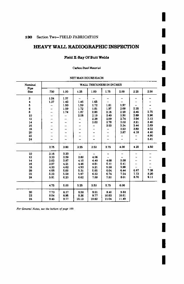
130
N o m i n a l
Section Two--FIELD FABRICATION
HEAVY WAT,T, RADIOGRAPHIC INSPEC'HON
Field X-Ray Of Butt Welds
Carbon Steel Material
N E T MAN H O U R S E A C H
WALL T H I C K N E S S IN I N C H E S
/
/
I /
I Pipe S ~ e
3 4 5 6 8 10 12 14 16 18 20 22 24
10 12 14 1 6
18 20 22 24
20 22 24
.750 1.00 1.25 1.50 1.75 2.00 2.25 2.50 �9 / 1 . 2 4 1.37 . . . . . . . . . . 1.37 1.43 1.46 1.65 . . . . .
- 1 . 5 0 1 . 5 9 1 . 7 2 1 . 8 1 1 . 9 7 - -
- 1.59 1.72 1.81 1.97 2.09 2.25 - -- 1.74 1.87 2.00 2.16 2.28 2.46 2.75 . . . . 2.08 2.19 2.40 2.50 2.69 2.96 / . . . . . 2.38 2.59 2.74 2.94 3.12 . . . . . . 2.62 2.78 3.02 3.21 3.40 . . . . . . . 3.03 3.24 3.44 3.69 . . . . . . . . 3 .53 3 .80 4 .02
. . . . . . . . . 3.87 4.10 4.40 |
. . . . . . . . . . . . 4.90
. . . . . . . . . . . 5.41
2.75 3.00 ! 3.25 3.50 3.75 4.00 4.25 4.50
3.16 3.33 . . . . . . . . . . 3.33 3.59 3.80 4.06 . . . . . . . 3.63 3.87 4.10 4.40 4.68 5.00 . . . . 3.97 4.21 4.46 4.81 5.11 5.41 -- - 4.33 4.62 4.93 5.21 5.58 5.98 . . . . 4.68 5.00 5.31 5.65 6.04 6.44 6.87 7.28 5.22 5.58 5.97 6.33 6.74 7.24 7.73 8.20 5.81 6.20 6.62 7.00 7.51 8.01 8.76 9.11
4.75 5.00 5.25 5.50 5.75 6.00
7.73 8.17 8.58 9.01 9.40 9.83 8.54 8.95 9.36 9.77 10.03 10.61 9.45 9.77 10.13 10.60 11.04 11.49
For General Notes, see the bottom of page I ~9.
I
I
I
I
I
I
I
I
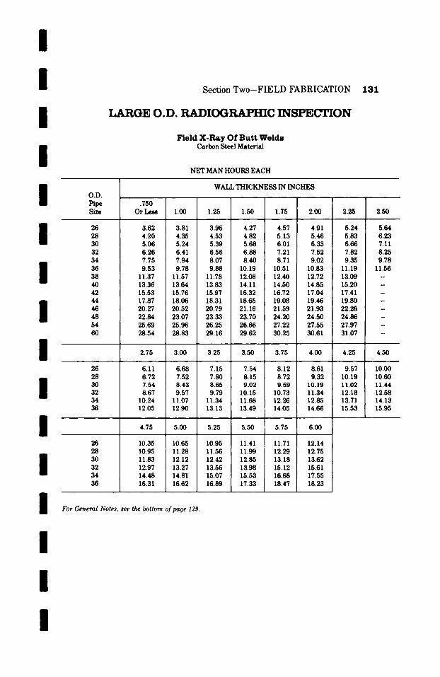
/ / / /
Section Two-FIELD FABRICATION
LARGE O.D. RADIOGRAPHIC INSPECTION
Field X-Ray Of Butt Welds Carbon Steel Material
NET MAN HOURS EACH
131
I / I / I I I I I I I
O . V .
Pipe Size
26 28 30 32 34 36 38 40 42 44 46 48 54 60
26 28 30 32 34 36
26 28 30 32 34 36
WALL THICKNESS IN INCHES
.750 Or Less 1.00 1.25 1.50 1.75 2.00 2.25
3.62 3.81 3.96 4.27 4.57 4.91 5.24 4.20 4.35 4.53 4.82 5.13 5.46 5.83 5.06 5.24 5.39 5.68 6.01 6.33 6.66 6.26 6.41 6.56 6.88 7.21 7.52 7.82 7.75 7.94 8.07 8.40 8.71 9.02 9.35 9.53 9.78 9.88 10.19 10.51 10.83 11.19
11.37 11.57 11.78 12.08 12.40 12.72 13.09 13.36 13.64 13.83 14.11 14.50 14.85 15.20 15.53 15.76 15.97 16.32 16.72 17.04 17.41 17.87 18.06 18.31 18.65 19.08 19.46 19.80 20.27 20.52 20.79 21.16 21.59 21.93 22.26 22.84 23.07 23.33 23.70 24.20 24.50 24.86 25.69 25.96 26.25 26.66 27.22 27.55 27.97 28.54 28.83 29.16 29.62 30.25 30.61 31.07
2.50
5.64 6.23 7.11 8.25 9.78
11.56 . .
N
N
2.75 3.00 3.25 3.50 3.75 4.00 4.25 4.50
6.11 6.68 7.15 7.54 8.12 8.61 9.57 10.00 6.72 7.52 7.80 8.15 8.72 9.32 10.19 10.60 7.54 8.43 8.65 9.02 9.59 10.19 11.02 11.44 8.67 9.57 9.79 10.15 10.73 11.34 12.18 12.58
10.24 11.07 11.34 11.68 12.26 12.85 13.71 14.13 12.05 12.90 13.13 13.49 14.05 14.66 15.53 15.95
4.75 5.00 5.25 5.50 5.75 6.00
10.35 10.65 10.95 11.41 11.71 12.14 10.95 11.28 11.56 11.99 12.29 12.75 11.83 12.12 12.42 12.85 13.18 13.62 12.97 13.27 13.56 13.98 15.12 15.61 14.48 14.81 15.07 15.53 16.68 17.55 16.31 16.62 16.89 17.33 18.47 18.23
For General Notes, see the bottom @page I'29.
I

1 3 2 S e c t i o n T w o - - F I E L D F A B R I C A T I O N
HYDROSTATIC TESTING
F o r P r e s s u r e s N o t E x c e e d i n g 4 , 0 0 0 P . S . I .
Carbon Steel Material
NET MAN HOURS PER LINEAR Fo(Yr
Standard Extra Hvy.
I I i i I
Pipe Size
Inches
2"Or Less 2-1/2"
3 4 5 6 8 10 12 14 O.D. 160.D. 18 O.D. 20 O.D. 24 O.D.
Pipe& O.D. Sizes 318"Thick
0.014 0.015
0.017 0.020 0.022 0.025 0.027 0.031 0.034 0.038 0.044 0.051 0.057 0.076
Pipe& O.D. Sizes I/2" Thick
0.016 0.017
0.019 0.024 0.026 0.029 0.032 0.035 0.039 0.044 0.049 0.058 0.067 0.086
20 30 40
~ 1 7 6
N N
N u
0.027 0.027 0.031 0.031 0.034 0.034 0.O38 0.038 0.044 0.044 0.051 0.055 0.057 0.067 0.076 0.087
0.014 0.015
0.017 0.020 0.022 0.025 0.027 0.031 0.038 0.041 0.049 0.064 0.078 0.115
SCHEDULE NUMBERS
60 80 I00 120 140 160
-- 0.016 . . . . . 0.025 -- 0.017 . . . . . . 0.028
-- 0.019 - - - 0.031 - 0.024 - 0.032 -- 0.036 - 0.026 -- 0.035 -- 0.041 -- 0.029 - 0.039 - 0.047
0.030 0.032 0.039 0.046 0.052 0.057 0.035 0.041 0.049 0.055 0.063 0.070 0.044 0.053 0.061 0.068 0.077 0.087 0.050 0.062 0.069 0.078 0.091 0.106 0.062 0.075 0.086 0.097 0.114 0.134 0.077 0.095 0.108 0.123 0.141 0.164 0.095 0.115 0.133 0.151 0.172 0.203 0.141 0.175 0.200 0.230 0.265 0.304
Above man hours are average for testing completed process systems, for a maximum holding time ofone hour, and include time for the following operations when required:
1) Place and remove blinds and blanks as required. 2) Opening and closing of valves. 3) Removal and replacement of valves, orifice plates, expansion joints, and short pieces of pipe as may be
required. 4) Block up and block removal of spring-supported or counterweight-sul;ported lines. 5) Air purging of lines before hydro-test. 6) Soap testing joints where required. 7) Drain lines after testing.
If individual segments or spools are to be tested separately multiply above man hours by a factor often (10).
/ / I I i i
i i I /
i
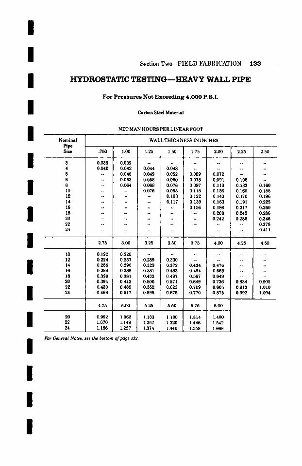
I /
I I I
Section Two-FIELD FABRICATION
HYDROSTATIC TESTING---HEAVY WALL PIPE
F o r P r e s s u r e s N o t E x c e e d i n g 4 , 0 0 0 P . S . I .
Carbon Steel Material
NET MAN HOURS PER LINEAR FOOT
Nominal WALL THICKNESS IN INCHES
133
I I I I I I I I I I
Pipe Size
3 4 5 6 8 10 12 14 16 18 20 22 24
I0 12 14 16 18 20 22 24
20 22 24
.750 1.00 1.25
0.035 0.039 - 0.040 0.042 0.044
- 0.046 0.049 -- 0.053 0.058 -- 0.064 0.068 - -- 0.076
1.50 1.75 2.00 2.25 2.50
0.048 . . . . . . . . 0.052 0.059 0.072 . . . . 0.060 0.078 0.091 i 0.106 --
i
0.076 0.097 0.113 0.133 0.160 0.095 0.118 0.136 0.160 0.188 0.103 0.122 0.143 0.170 0.196
I
0.117 0.139 0.163 0.191 0.225 -- 0.156 0.186 0.217 0.260 . . . . 0.208 0.242 0.286 . . . . 0.242 0.286 0.346 . . . . . . . . 0.378 . . . . . . . . 0.411
2.75 3.00 3.25 3.50 3.75 4.00 4.25 4.50
0.220 0.257 0.290 0.338 0.381 0.442 0.485 0.517
~ 1 7 6
0.289 0.329 0.381 0.433 0.506 0.552 0.598
0.192 0.224 0.256 0.294 0.328 0.394 0.430 0.468
0 . 3 3 0 . . . . . . . 0 . 3 7 2 0 . 4 2 4 0 . 4 7 6 . . . .
0.433 0.494 0.563 . . . . 0.497 0.567 0.649 . . . . 0.571 0.649 0.736 0.834 0.905 0.623 0.709 0.805 0.913 1.010 0.676 0.770 0.875 0.992 1.094
4.75 5.00 5.25 5.50 5.75 6.00 �9 , ,
0.992 1.062 1.133 1.180 1.314 1.400 1.070 1.149 1.257 1.320 1.446 1.542 1.168 1.257 1.374 1.440 1.558 1.666
For General Notes, see the bottom of page 132.
I

134 Section Two--FIELD FABRICATION
HYDROSTATIC T E S T I N G - - L A R G E O.D. P I P E
For P r e s s u r e s N o t E x c e e d i n g 4 , 0 0 0 P . S . I .
Carbon Steel Material
NET MAN HOURS PER LINEAR FOOT
/ / / /
I O.V. Pipe
Inches
26 28 30 32 34 36 38 40 42 44 46 48 54 60
26 28 30 32 34 36
26 28 30 32 34 36
.500 or Less .750
0.140 0.161 0.162 0.186 0.194 0.223 0.241 0.277 0.299 0.344 0.368 0.423 0.438 0.504 0.517 0.595 0.600 0.690 0.690 0.794 0.780 0.897 0.881 1.013 0.987 1.135 1.096 1.260
WALL THICKNESS IN INCHES
1.00 1.25 1.50 1.75 2.00 2.25
0.185 0.213 0.245 0.281 0.323 0.389 0.214 0.246 0.283 0.326 0.375 0.431 0.257 0.296 0.340 0.391 0.450 0.518 0.319 0.367 0.422 0.485 0.558 0.642 0.396 0.455 0.523 0.601 0.691 0.795 0.487 0.560 0.644 0.741 0.852 0.980 0.580 0.667 0.767 0.882 1.014 1.166 0.684 0.787 0.905 1.041 1.197 1.377 0.794 0.913 1.050 1.208 1.389 1.597 0.913 1.050 1.208 1.389 1.597 1.837 1.032 1.187 1.365 1.570 1.806 2.077 1.165 1.340 1.541 1.772 2.038 2.344 1.305 1.501 1.726 1.985 2.283 2.626 1.449 1.666 1.916 2.203 2.534 2.914
2.50 2.75 3.00 3.25 3.50 3.75 4.00 4.25
0.447 0.509 0.562 0.650 0.735 0.837 0.951 1.078 0.492 0.561 0.617 0.716 0.809 0.922 1.051 1.188 0.551 0.628 0.691 0.802 0.906 1.033 1.178 1.331 0.738 0.841 0.925 1.073 1.213 1.383 1.577 1.782 0.914 1.042 1.146 1.329 1.502 1.712 1.952 2.206 1.127 1.285 1.414 1.640 1.853 2.112 2.408 2.721
4.50 4.75 5.00 5.25 5.50 5.75 6.00
1.189 1.269 1.260 1.348 1.361 1.456 1.960 2.097 2.427 2.597 2.993 3.203
For General Notes, see the bottom of page 13~.
1.366 1.493 1.565 1.693 1.810 1.456 1.587 1.666 1.799 1.925 1.573 1.715 1.801 1.945 2.081 2.265 2.469 2.593 2.800 2.996 2.805 3.058 3.211 3.468 3.711 3.459 3.770 3.959 4.276 4.575
I /
I /
I / / /
I / /

I /
I /
Section Two--FIELD FABRICATION
ACCESS HOLES
Carbon Steel Material
NET MAN HOURS EACH
135
I I I I I
Nominal Pipe Size
2- I/2, 3, 4
5 , 6 , 8
10,12
14, 16, 18
20,22,24
26, 28, 30
32,34,36
38,40,42
44,46,48
54,60
WALL THICKNESS
UpTo I"
1.8
2.0
2.2
2.3
OVER l"to 2"
2.0
2.2
2.4
2.5
OVER 2" to 2- I/2"
2.6
2.9
3.0
OVER 2-1/2" to 4"
4.0
4.3
2.5
2.9
3.1
3.3
3.7
4.6
2.9
3.2
3.3
3.7
4.0
4.9
3.1
3.3
3.7
4.0
4.4
5.4
4.5
4.8
5.1
5.6
6.7
8.3
OVER 4" to6"
6.8
7.2
7.6
8.4
10.1
12.5
/ / / / /
I
Man hours include access holes through 1" diameter (drilled and tapped) for radiographic inspection of welds when specified or required.
For openings larger than 1" in diameter, add 25% to the above man hours for each �88 increase in diameter.
If plugs are to be included and seal welded, add 0.75 man hours each.
I
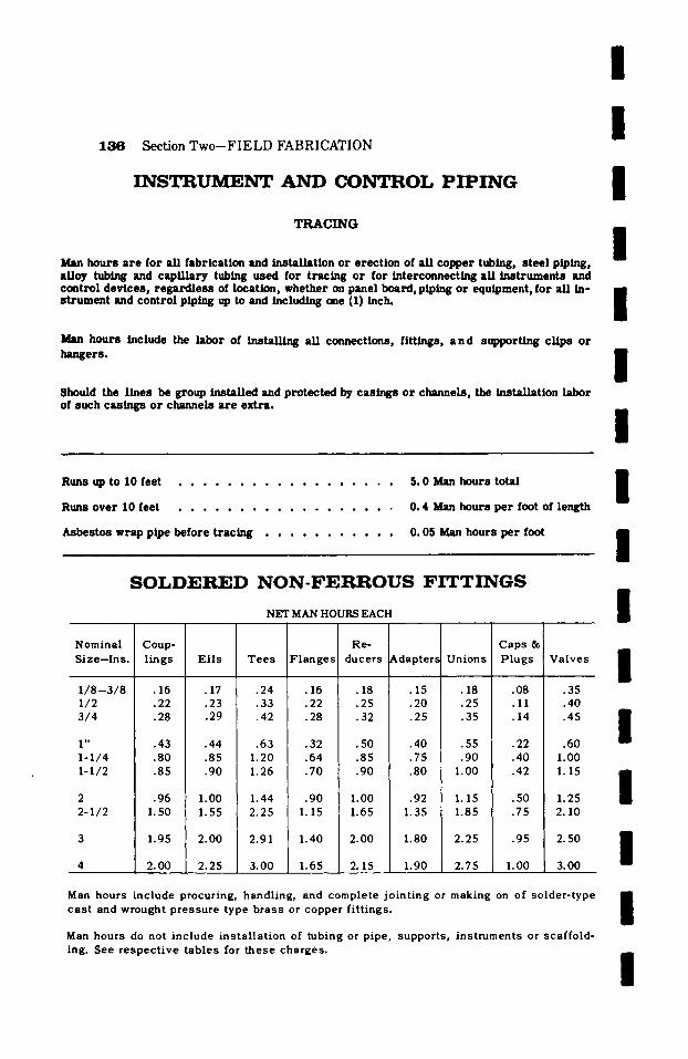
1 3 6 Sec t ion T w o - - F I E L D F A B R I C A T I O N
I N S T R U M 3 ~ N T A N D (X)N'rKOL P I P I N G
T R A C I N G
Man hours a r e for all fabricat ion and instal lat ion or erect ion of al l copper tubing, s tee l piping, alloy tubing and cap/ l la ry tubing used for t rac ing or for interconnect ing all ins t ruments and ccmtrol devices , r e g a r d l e s s of location, whether on panel board, piping or equipment, for all in- s t rumen t and control piping up to and including one (1) inch.
Man hours include the labor of instal l ing all connections, fittings, a n d suplmrting c l ips o r hangers .
Should the l ines be g roup /ns t aUed and pro tec ted by cas ings o r channels , the instal lat ion labor of such casings or channels are extra .
/ /
I /
I I I
R u n s up t o 1 0 f e e t . . . . . . . . . . . . . . . . . .
R u n s o v e r 1 0 f e e t . . . . . . . . . . . . . . . . . .
Asbestos wrap pipe before t rac ing . . . . . . . . . . .
5. 0 Man hours total
0. 4 Man hours pe r foot of length
0. 05 Man hours pe r foot
S O L D E R E D N O N - F E R R O U S F I T T I N G S
NET MAN HOURS EACH
Nominal Size-Ins.
1 / 8 - 3 / 8 1/2 3 /4
1" I-1/4 I-1/2
2 2-1 /2
Coup- Re- lings Ells Tees Flanges ducers Adapters Unions
�9 16 .17 .24 .16 .18 .15 .18 �9 22 .23 .33 .22 .25 .20 .25 �9 28 .29 .42 .28 .32 .25 .35
.43 .44 .63 .32 .50 .40
.80 .85 1.20 .64 .85 .75
.85 .90 1.26 .70 .90 .80
�9 9 6 1. O0 1 . 4 4 �9 9 0 1. O0 �9 92 1.50 1.55 2.25 1.15 1.65 1.35
I. 9 5 2.00 2.91 I. 40 2.00 I. 80
2.00 2.25 3.00 1.65 2. 15 1.90
.55
.90 1.00
1.15 1.85
2.25
2.75
Caps & P lugs
. 0 8
.11
.14
.22
.40
.42
.50
.75
.95
1.00
Valves
.35
.40
.45
.60 1.00 1.15
1.25 2.10
2.50
3.00
Man hours include procuring, handling, and complete jointing or making on of solder-type cast and wrought pressure type brass or copper fittings.
Man hours do not inc lude i n s t a l l a t i on of tubing or pipe, suppor ts , ins t ruments or scaf fo ld- ing. See r e s p e c t i v e t ab l e s for t he se charges .
I I
I I I I I I I

I I I I I I I I I
Size Ins.
1/2 3 /4
1
1-1/4 1-1/2
2 2-I/2
10
12
Section T w o - F I E L D FABRICATION 137
P V C - P L A S T I C P I P E
MAN HOURS P E R UNITS L I S T E D
Handle Pipe PerL. F.
.07
.07
.07
.08
.08
.09
.09
.10
.11
.12
.14
.17
.20
Cemented Socke t J o i n t s - Ea.
.20
.22
.25
.27 �9 29
.33
.38
.45
.55
.70
.80
1.00
Saddles Each
.38
.39
.40
.43
.45
.50
.55
.63
.73
.90
1.00
1.20
1.25 1.40
Hand le V a l v e s PCV Body -- Ea.
.13
.16
.17
.20
.25
.35
.58
.85
1.25
1.60
1.95
2.50
3. O0
I I I I I I
Handle Pipe Units: Man hours include handling, hauling rigging and aligning in place.
Cement Socket Joint Units: Man hours include cut, square, ream, fit-up and make joint.
Saddle Units: Man hours include fit-up, drill hole in header and cement saddle to header. Maximum hole size is assumed to be 11/~ inch. For larger branch lines the use of tees should be estimated. The size of the header not the size of the saddle determines the man hours that apply.
Handle Valve Units: Man hours include handling, hauling and positioning of valve only. Connections of the type as required must be added.
Units are for all wall thickness.
Uni ts do not inc lude scaf fo ld ing �9 See r e s p e c t i v e tab le for th is charge .
I
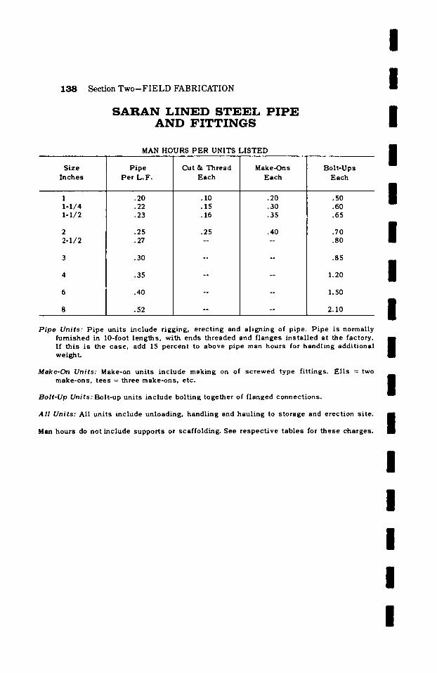
1 3 8 Section Two--FIELD FABRICATION
S A R A N L I N E D S T E E L P I P E A N D F I T T I N G S
MAN HOURS P E R UNITS LISTED
I I I I
Size Inches
1 1 -1 /4 1-1/2
2 2 - I / 2
P ipe Pe r L . F .
.20
.22
.23
.25
.27
.30
.35
.40
.52
Cut & Thread Each
. I0
.15
.16
.25
Make-Ons Each
.20
.30
.35
.4O
Bolt -Ups Each
.50
.60
.65
I 7o l .80
.85
1.20
1.50
2.10
/ /
Pipe Units: Pipe uni t s inc lude rigging, e rec t ing and a l ign ing of pipe. P i p e is normally furn ished in 10-foot lengths , with ends th readed and f langes i n s t a l l ed at the factory, i If th is is the case , add 15 percen t to above pipe man hours for handl ing addi t iona l $ weight.
Make-On Units: Make-on un i t s inc lude making on of s c r ewed type f i t t ings. E l l s = two make-ons , t ee s = three make-ons , etc.
Bolt-Up Units: Bolt-up uni t s inc lude bol t ing toge ther of f langed connec t ions .
Al l Units: All un i t s inc lude unloading, handl ing and hau l ing to s torage and e rec t ion s i te .
Man hours do not inc lude suppor t s or scaffolding. See r e s p e c t i v e t ab les for t he se charges .
I / / /
I / /
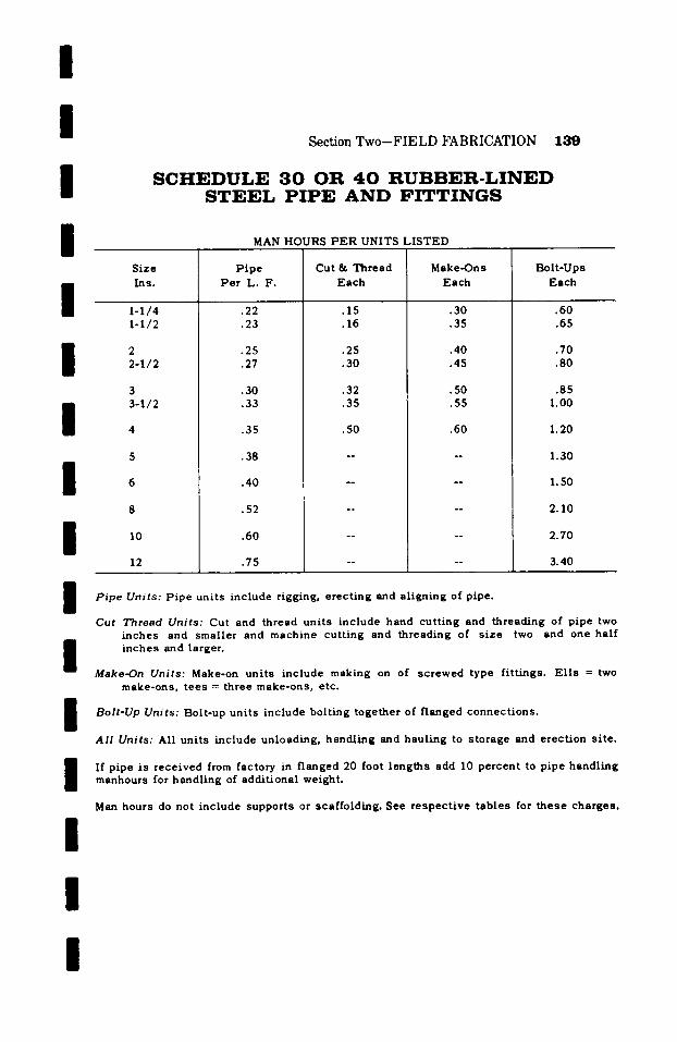
/
I / /
Section Two-FIELD FABRICATION 139
S C H E D U L E 3 0 O R 4 0 R U B B E R - L I N E D S T E E L P I P E A N D F I T T I N G S
MAN HOURS P E R UNITS LI S TED
I I I I I I I I I I I
Size Ins.
1-1/4 1-1/2
2 2-1 /2
3 3-1/2
I0
12
Pipe Per L. F.
.22
.23
.25
.27
.30
.33
.35
.38
.40
.52
.60
.75
Cut & Thread Each
.15
.16
.25
.30
.32
.35
Make-Ons Each
.30
.35
.40
.45
.50
.55
.50 .50
Bol t -Ups Each
.60
.65
.70
.80
.85 I. O0
1.20
1.30
1.50
2.10
2.70
3.40
P i p e Uni t s : Pipe uni t s inc lude rigging, e rec t ing and a l igning of pipe.
Cut T h r e a d Uni t s : Cut and thread un i t s inc lude hand cu t t ing and th read ing of pipe two inches and smal le r and machine cu t t ing and threading of s i z e two and one ha l f i nches and larger.
Make-On Uni t s : Make-on un i t s inc lude making on of s c r ewed type f i t t ings . E l l s = two make-ons , t e e s = three make-ons , etc.
Bolt-Up Units: Bolt-up units include bolting together of flanged connections.
All Units: All units include unloading, handling and hauling to storage and erection site.
If pipe is r ece ived from factory in f langed 20 foot l eng ths add I0 pe rcen t to p ipe hand l ing manhours for hand l ing of addi t iona l weight .
Man hours do not inc lude suppor t s or scaf fo ld ing . See r e s p e c t i v e t a b l e s for t h e s e charges .
I

1 4 0 Section Two-FIELD FABRICATION
S C H E D U L E 4 0 L E A D L I N E D S T E E L P I P E A N D F I T T I N G S
MAN HOURS P E R UNITS LI S TED
I I l l
Pipe Size
1-1/4 1-1/2
2 2 -1 /2
3 3-112
10
12
Handle P ipe
Per L. F.
.22
.25
.33
.35
.40
.45
.50
.65
.80
1.20
1.60
2.25
Cut and Thread Each
.15
.16
.25
.30
.33
.35
.50
Make*Ons Each
.30
.35
.38
.40
.45
.47
.55
Butt Welds Incl. Lead Boming Each
.90 1.10
1.30 1.45
1.55 1.65
1.85
2.20
2.80
3.40
4.30
5.55
Bolt-Ups Each
.60
.65
.70
.80
.85 1.00
I. 20
1.35
1.50
2.10
2.70
3.40
Pipe Units: Pipe units include rigging, erecting and aligning of pipe. It is customary to
I l I I l l
order th is type piping p re fab r i ca t ed with lead l ined f i t t ings in p lace . Should this be the c a s e add 20 pe rcen t to handl ing pipe uni t s for e l iminat ion of f ield make-ons and handl ing of addi t iona l weight .
Cut and Thread Units: Cut and thread units include hand cutting and threading of pipe two inches and smaller and machine cutting and threading of sizes two and one half inches and larger.
Make-On Units: Make-on units include making on of screwed type fittings. Ells = two make-ons, tees = three make-ons, etc.
Butt Welds: Butt welds including lead burning units include circumfemtial manual elec- tric weld and fusing together of lead at joint.
Bolt-Up Units: Bolt-up units include bolting together of flanged connections.
All Units: All units include unloading, handling and hauling to storage and erection site.
Man hours do not inc lude suppor t s or scaf fo ld ing . See r e s p e c t i v e t ab les for t h e s e charges .
I I I I I l
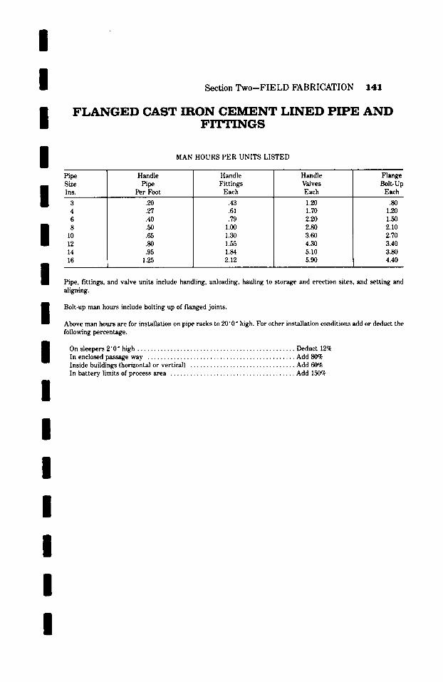
/ / / I
Section Two-FIELD FABRICATION 141
F L A N G E D CAST IRON C E M E N T L I N E D P I P E A N D F I T T I N G S
MAN HOURS PER UNITS LISTED
/ / /
Pipe Size Ins.
3 4 6 8
10 12 14 16
Handle Pipe
Per Foot
.20
.27
.40
.50
.65
.80
.95 1.25
Handle Fittings Each
.43
.61
.79 1.00 1.30 1.55 1.84 2.12
Handle Valves Each
1.20 1.70 2.20 2.80 3.60 4.30 5.10 5.90
Flange Bolt-Up
Each
.80 1.20 1.50 2.10 2.70 3.40 3.80 4.40
Pipe, fittings, and valve units include handling, unloading, hauling to storage and erection sites, and setting and
/ / / / / / /
I
aligning.
Bolt-up man hours include bolting up of flanged joints.
Above man hours are for installation on pipe racks to 20'0" high. For other installation conditions add or deduct the follo~ng percentage.
On sleepers 2'0" high ................................................ Deduct 12% In enclosed passage way ............................................. Add 80% Inside buildings (horizontal or vertical) ................................ Add 60~ In battery limits of process area ...................................... Add 150~
I

142 Section Two-FIELD FABRICATION
S C H E D U L E 4 0 C E M E N T L I N E D C A R B O N S T E E L P I P E W I T H S T A N D A R D F I T T I N G S
MAN HOURS PER UNITS LISTED
I I I I Pipe
Size Ins.
10
12
14
16
18
20
24
H a n d l e P i p e
P e r F o o t
.40
.50
.65
.80
.95
1.25
1.40
1.75
2.20
C u t t i n g P i p e
P e r Cut
.65
1.00
1.20
1.45
2.30
2 .95
3 .70
4 .65
5.90
But t Welds E a c h
2.0
2.6
3.1
4.1
5.0
6.6
8.6
9.4
13.3
S l e e v e Joint With Two
Welds Each
3.30
4.60
5.70
6 .90
7.90
9.20
10.40
12.40
15.50
90 ~ Welded Nozzle Each
6.05
7.30
8 .30
11.35
13.90
18.15
22.80
26.95
33.60
Smooth On Cemen t
P e r J o i n t
.35
.50
.60
.65
.80
.95
I. I0
1.25
1.50
I I I I I
Handle Pipe Units" Man hours include handling, unloading, hauling to storage and erec- tion site and setting and aligning.
Cuttin~ Pipe Units" Man hours include cutting pipe and lining. Lining to be cut square and flush with ends.
Butt Weld Units: Man hours include making complete electric weld. Cement lining should be wet with water around welding area.
Sleeve Joint Units: Man hours include slipping on of sleeve, aligning and welding at both ends.
90 ~ Welded Nozzle Units: Man hours include complete operations for welding nozzle.
Smooth on Cement Units: Man hours include mixing and patching weld joints with cement.
Man hours do not include excavation or racks or supports. See respeotive tables for these charges.
I I I I I I I

/
I /
I / / /
Section Two-FIELD FABRICATION 143
D O U B L E T O U G H P Y R E X P I P E A N D F I T T I N G S
MAN HOURS PER UNITS LISTED
Pipe Size
1 1-I/2
Erect Spool P iece
Pipe P e r L . F.
.35
.45
.55
.66
.75
1.00
1.30
Standard Bolt-Up Each
.35
.40
.45
.55
.85
.95
1.00
Split Flange Bolt-Up Each
.50
.70
.80
.90
1.33
1.50
2.00
I I I I I I I I
Pyrex pipe is usual ly ordered from factory prefabricated into spool p ieces with all necessary fittings and standard flanges in place. Should pipe be ordered without factory ins ta l led flanges it is good pract ice to ins ta l l spli t type flanges in the field.
Above man hours are based on installing factory fabricated spool pieces, up to 10 feet long, in the field and include all handling, unloading and hauling to storage and erection site.
Spool Piece Units: Spool piece units include rigging, erecting and aligning.
Standard Bolt-Up Units: Standard bolt-up units include bolting up of factory furnished fabricated flanges.
Split Flange Bolt-Up Units: Split flange bolt-up units include all operations necessary for the slipping on of flanges and gaskets and bolting-up.
Man hours do not include installation of hangers or supports or the erection of scaffold- ing. See respective tables for these charges.
I
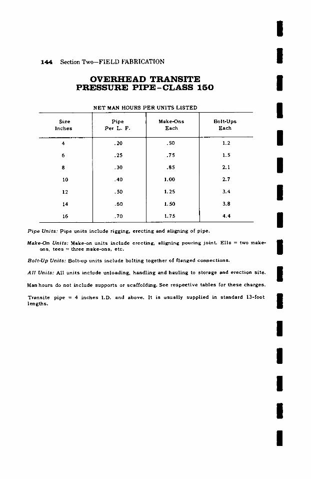
/
1 4 4 S e c t i o n T w o - - F I E L D F A B R I C A T I O N /
O V E R H E A D T R A N S I T E P R E S S U R E P I P E - C L A S S 1 5 0 I
NET MAN HOURS PER UNITS LISTED I Size
Inches
10
12
14
16
Pipe Per L. F.
.20
.25
.30
.40
.50
.60
.70
Make*Ons Each
.50
.75
.85
1.00
1.25
1.50
1.75
B o l t - U p s
E a c h
1.2
1.5
2.1
2.7
3.4
3.8
4.4
I I I I
Pipe Units: Pipe units include rigging, erecting and aligning of pipe.
Make-On Uni t s : Make-on u n i t s i n c l u d e e r e c t i n g , a l i g n i n g pour ing jo in t . E l l s = two make* ons, t e e s = th ree m a k e - o n s , e tc .
Bolt-Up Units: Bolt-up units include bolting together of flanged connections.
All Units: All units include unloading, handling and hauling to storage and erection site.
Man hours do not include supports or scaffolding. See respective tables for these charges.
Transite pipe = 4 inches I.D. and above. It is usually supplied in standard 13-foot lengths.
l I I I I I I I
I / / S e c t i o n T h r e e
A L L O Y
I AND N O N - F E R R O U S F A B R I C A T I O N
/ / /
This section is intended to cover the complete shop fabrication and field fabrication and erection of alloy and non-ferrous piping. Alloy and non-ferrous piping operations are to be man houred on the same basis as corresponding carbon steel materials, plus the percentage given in the following tables applicable to the carbon steel man hours listed in sections one and two.
/ / /
I / / / /
146
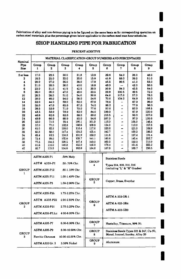
Fabrication of alloy and non-ferrous piping is to be figured on the same basis as for corresponding operation on carbon steel materials, plus the percentage given below applicable to the carbon steel man hour schedules.
SHOP HANDI.ING PIPE FOR FABRICATION
PERCENT ADDITIVE
I I I
MATERIAL CLASSIFICATION-GROUP NUMBERS AND PERCENTAGES Nominal /
Pipe Group Group Group Group Group Group Group Group Group Size 1 2 3 4 5 6 7 8 9
2 or less 17.0 22.5 30.0 31.8 13.0 39.0 84.0 36.0 46.0 3 18.5 25.0 33.0 35.0 15.0 41.0 88.0 39.0 51.0 4 20.0 27.0 36.0 38.0 17.0 45.5 90.5 41.0 55.0 5 21.0 28.0 38.0 40.0 18.0 49.0 - - 42.0 58.0 6 23.0 31.0 41.5 42.5 20.0 50.0 94.0 43.5 64.0 8 26.0 35.0 47.0 48.0 33.5 59.0 100.5 49.5 72.0
10 28.5 38.0 51.0 54.0 ! 50.0 64.0 117.0 57.0 78.0 12 30.0 40.0 54.0 58.0 54.0 70.0 134.0 64.0 83.0 14 33.0 44.0 ! 59.0 62.0 67.0 78.0 -- 67.0 90.0 16 35.0 47.0 63.0 67.0 74.0 86.0 - 77.0 96.0 18 39.5 53.0 71.0 75.0 77.0 92.0 - 82.0 108.5 20 43.5 58.0 78.0 83.0 84.0 100.0 - 87.0 120.0 22 46.0 62.0 83.0 88.0 89.0 103.5 j -- 93.0 127.0 24 49.0 66.0 88.0 93.0 94.0 107.0 - 97.0 135.0 26 53.0 71.5 95.4 100.1 101.9 116.0 -- 105.0 146.4 28 57.0 77.0 102.8 108.6 109.8 124.9 -- 113.0 157.6 30 61.0 82.5 110.0 116.4 117.6 133.8 -- 121.0 168.9 32 65.3 88.0 117.4 124.2 125.4 142.7 -- 129.3 180.2 34 69.4 93.5 124.8 131.9 133.3 151.6 -- 137.4 191.4 36 73.4 99.0 132.0 139.7 141.1 160.6 -- 145.4 202.7 38 77.5 104.5 139.5 147.4 149.0 169.5 -- 153.5 213.9 40 81.6 110.0 146.8 155.2 156.8 178.4 -- 161.6 225.2 42 85.7 115.5 154.0 163.0 164.6 187.3 -- 169.7 236.5
/ / / I /
GROUP 1
GROUP 2
GROUP 3
ASTM A335-P1 .50% Moly
ASTM A335-P2 .50-.70% Chr.
ASTM A335-P12 .85-1.10% Chr.
ASTM A335-P11 1.05-1.45% Chr.
ASTM A335-P3 1.50-2.00% Chr.
ASTM A335-P3b 1.75-2.25% Chr.
ASTM A335-P22 2.00-2.50% Chr.
ASTM A335-P21 2.75-3.25% Chr.
ASTM A335-P5,b,c 4.00-6.00% Chr.
ASTM A335-P7 6.00-8.00% Chr.
ASTM A335-P9 8.00- I0.00~ Chr.
Ferritic Chromes I0.00-15.00% Chr.
ASTM A333 Gr. 3 3.50% Nickel
GROUP 4
GROUP 5
GROUP 6
GROUP 7
GROUP 8
GROUP
Stainless Steels
Types 304, 309, 310,316 (including "L" & "H" Grades)
Copper, Brass, Everdur
ASTM A-333-GR- 1
ASTM A-333-GR4
ASTM A-333-GR9
Hastelloy, Titanium, 99% Ni.
Stainless Steels Types 321 & 347, Cu-Ni, Monel, Inconel, lncoloy, Alloy 20
Aluminum
I / / /
I / /
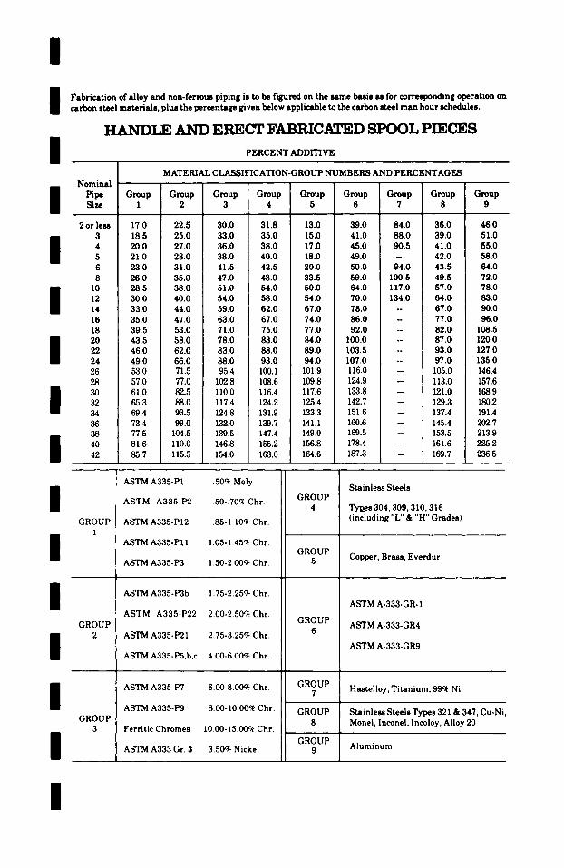
l l l
Fabrication of alloy and non-ferrous piping is to be t '~ured on the same basis as for corresponding operation on carbon steel materials, plus the percentage given below applicable to the carbon steel man hour schedules.
HANDI,R AND ERECT FABRICATED SPOOL PIECES
PERCENT ~ D m V E
MATERIAL CLASSIFICATION-GROUP NUMBERS AND PERCENTAGES Nominal
Pipe Group Group Group Group Group Group Group Group Size 1 2 3 4 5 6 7 8
2 or less 17.0 22.5 30.0 31.8 13.0 39.0 84.0 36.0 3 18.5 25.0 33.0 35.0 15.0 41.0 88.0 39.0
I 4 20.0 27.0 36.0 38.0 17.0 45.0 90.5 41.0 5 21.0 28.0 38.0 40.0 18.0 49.0 -- 42.0 6 23.0 31.0 41.5 42.5 20.0 50.0 94.0 43.5 8 26.0 35.0 47.0 48.0 33.5 59.0 100.5 49.5
10 28.5 38.0 51.0 54.0 50.0 64.0 117.0 57.0 12 30.0 40.0 54.0 58.0 54.0 70.0 134.0 64.0 14 33.0 44.0 59.0 62.0 67.0 78.0 -- 67.0 16 35.0 47.0 63.0 67.0 74.0 86.0 - 77.0 18 39.5 53.0 71.0 75.0 77.0 92.0 -- 82.0 20 43.5 58.0 78.0 83.0 84.0 100.0 -- 87.0 22 46.0 62.0 83.0 88.0 89.0 103.5 - 93.0 24 49.0 66.0 88.0 93.0 94.0 107.0 -- 97.0 26 53.0 71.5 95.4 100.1 101.9 116.0 -- 105.0 28 57.0 77.0 102.8 108.6 109.8 124.9 -- 113.0 30 61.0 82.5 110.0 116.4 117.6 133.8 -- 121.0 32 65.3 88.0 117.4 124.2 125.4 142.7 -- 129.3 34 69.4 93.5 124.8 131.9 133.3 151.6 -- 137.4 36 73.4 99.0 132.0 139.7 141.1 160.6 -- 145.4 38 77.5 104.5 139.5 147.4 149.0 169.5 -- 153.5 40 81.6 110.0 146.8 155.2 156.8 178.4 -- 161.6 42 85.7 115.5 154.0 163.0 164.6 187.3 -- 169.7
Group 9
46.0 51.0 55.0 58.0 64.0 72.0 78.0 83.0 90.0 96.0
108.5 120.0 127.0 135.0 146.4 157.6 168.9 180.2 191.4 202.7 213.9 225.2 236.5
l l l l l l
GROUP I
GROUP 2
GROUP 3
ASTM A335-P1 .50c~ Moly
ASTM A335-P2 .50-.70% Chr.
ASTM A335-PI2 .85-I.I0~ Chr.
ASTM A335-PI 1 1.05-1.45% Chr.
ASTM A335-P3 1.50-2.00c~ Chr.
ASTM A335-P3b 1.75-2.25% Chr.
ASTM A335-P22 2.00-2.50% Chr.
ASTM A335-P21 2.75-3.25~ Chr.
ASTM A335-P5,b,c 4.00-6.00~ Chr.
ASTM A335-P7 6.00-8.00~ Chr.
ASTM A335-P9 8.00-10.00c~ Chr.
Ferritic Chromes 10.00-15.00~ Chr.
ASTM A333 Gr. 3 3.50~ Nickel
GROUP 4
GROUP 5
GROUP 6
GROUP 7
GROUP 8
GROUP 9
Stainless Steels
Tyl~es 304,309, 310,316 (including "L" & "H" Grades)
Copper, Brass, Everdur
ASTM A-333-GR- 1
ASTM A-333-GR4
ASTM A-333-GR9
Hastelloy, Titanium, 99~ Ni.
Stainless Steels Types 321 & 347, Cu-Ni, Monel, lnconel, lncoloy, Alloy 20
Aluminum
/
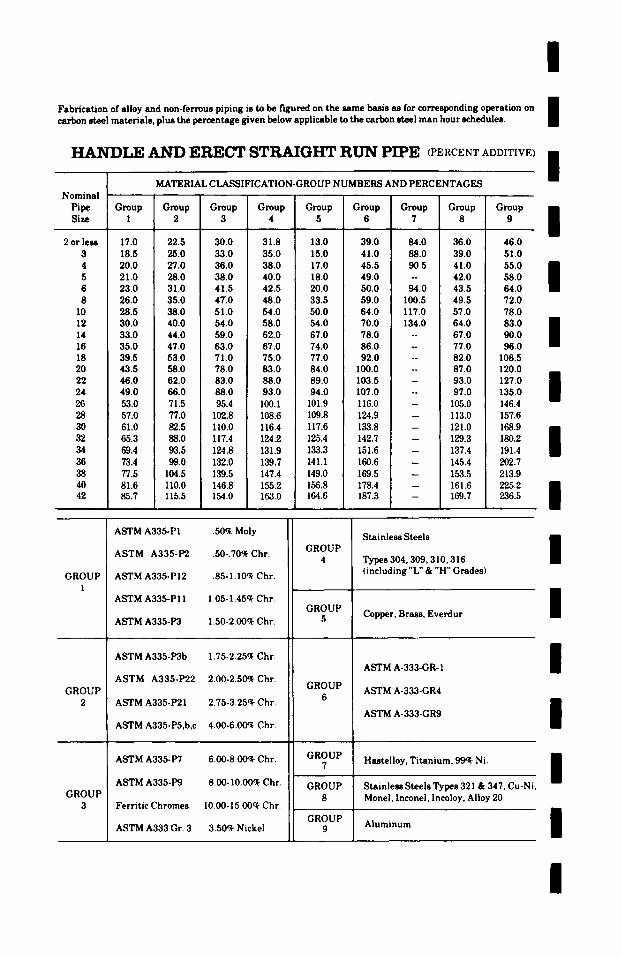
i Fabrication of alloy and non-ferrous piping is to be figured on the same basis as for corresponding operation on carbon steel materials, plus the percentage given below applicable to the carbon steel man hour schedules.
H A N D L E A N D ERECT STRAIGHT R U N PIPE (PERCENT ADDITIVE)
i / / / / / /
MATERIAL CLASSIFICATION-GROUP NUMBERS AND PERCENTAGES Nominal
Pipe Group Group Group Group Group Group Group Group Group Size 1 2 3 4 5 6 7 8 9
2 or less 17.0 22.5 30.0 31.8 13.0 39.0 84.0 36.0 46.0 3 18.5 25.0 33.0 35.0 15.0 41.0 88.0 39.0 51.0 4 20.0 27.0 36.0 38.0 17.0 45.5 90.5 41.0 55.0 5 21.0 28.0 38.0 40.0 18.0 49.0 -- 42.0 58.0 6 23.0 31.0 41.5 42.5 20.0 50.0 94.0 43.5 64.0 8 26.0 35.0 4T.0 48.0 33.5 59.0 100.5 49.5 72.0
10 28.5 38.0 51.0 54.0 50.0 64.0 117.0 57.0 78.0 12 30.0 40.0 54.0 58.0 54.0 70.0 134.0 64.0 83.0 14 33.0 44.0 59.0 62.0 67.0 78.0 -- 67.0 90.0 16 35.0 47.0 63.0 67.0 74.0 86.0 - 77.0 96.0 18 39.5 53.0 71.0 75.0 77.0 92.0 -- 82.0 108.5 20 43.5 58.0 78.0 83.0 84.0 I00.0 -- 87.0 120.0 22 46.0 62.0 83.0 88.0 89.0 103.5 - 93.0 127.0 24 49.0 66.0 88.0 93.0 94.0 107.0 -- 97.0 135.0 26 53.0 71.5 95.4 100.1 101.9 116.0 105.0 146.4 28 57.0 77.0 102.8 108.6 109.8 124.9 113.0 157.6 30 61.0 82.5 II0.0 116.4 117.6 133.8 121.0 168.9 32 65.3 88.0 117.4 124.2 125.4 142.7 129.3 180.2 34 69.4 93.5 124.8 131.9 133.3 151.6 137.4 191.4 36 73.4 99.0 132.0 139.7 14 I. 1 160.6 145.4 202.7 38 77.5 104.5 139.5 147.4 149.0 169.5 153.5 213.9 40 81.6 1 I0.0 146.8 155.2 156.8 178.4 161.6 225.2 42 85.7 115.5 154.0 163.0 164.6 187.3 169.7 236.5
_
GROUP 1
GROUP 2
GROUP 3
ASTM A335-PI .50% Moly
ASTM A335-P2 .50-.70q~ Chr.
ASTM A335-P12 .85-1.10~ Chr.
ASTM A335-P11 1.05-1.45~c Chr.
ASTM A335-P3 1.50-2.00% Chr.
ASTM A335-P3b 1.75-2.25q~ Chr.
ASTM A335-P22 2.00-2.50~ Chr.
ASTM A335-P21 2.75-3.25~ Chr.
ASTM A335-P5,b,c 4.00-6.00~ Chr.
ASTM A335-P7 6.00-8.00q~ Chr.
ASTM A335-P9 8.00-10.0(O Chr.
Ferritic Chromes I0.00-15.00c~ Chr.
ASTM A333 Gr. 3 3.50~ Nickel
GROUP 4
GROUP 5
GROUP 6
GROUP 7
GROUP 8
GROUP
Stainless Steels
Types 304,309, 310, 316 (including "L" & "H" Grades)
Copper, Brass, Everdur
ASTM A-333-GR- 1
ASTM A-333-GR4
ASTM A-333-GR9
Hastelloy, Titanium, 99~ Ni.
Stainless Steels Types 321 & 347, Cu-Ni, Monei, Inconel, Incoloy, Alloy 20
Aluminum
i
i i i I I I i
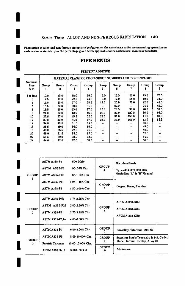
/
/ /
/
Section Three--ALLOY AND NON-FERROUS FABRICATION 1 4 9
Fabrication of alloy and non-ferrous piping is to be figured on the same basis as for corresponding operation on carbon steel materials, plus the percentage given below applicable to the carbon steel man hour schedules.
PIPE BENDS
PERCENT ADDITIVE
/ / / / I
Nominal Pipe Size
2 or less 3 4 5 6 8
10 12 14 16 18 20 22 24
MATERIAL CLASSIFICATION-GROUP NUMBERS AND PERCENTAGES
Group Group Group Group Group Group Group Group Group 1 2 3 4 5 6 7 8 9
10.0 13.0 18.0 19.0 6.0 13.5 50.0 15.0 27.5 12.5 17.0 22.5 24.0 9.0 17.0 65.0 19.0 34.0 15.0 20.0 27.0 28.5 12.0 20.0 75.0 22.0 41.0 16.5 22.0 30.0 31.0 - 22.0 -- 24.0 45.0 19.5 26.0 35.0 37.0 15.0 23.0 90.0 26.0 53.5 24.0 32.0 43.0 46.0 20.0 27.0 120.0 30.0 66.0 27.5 37.0 49.5 52.0 22.0 37.0 150.0 41.0 69.0 30.0 40.0 54.0 57.0 25.0 39.0 165.0 43.0 82.5 34.0 45.5 61.0 64.5 . . . . . . 46.0 - 36.5 49.0 66.0 69.0 . . . . . . 49.0 - 40.0 53.5 72.0 76.0 . . . . . . 50.0 - 46.0 61.5 83.0 87.0 . . . . . 52.0 - 51.5 69.0 93.0 98.0 . . . . . 54.0 -- 54.0 72.0 97.0 103.0 . . . . 56.0 --
/ / /
/
/ /
GROUP 1
GROUP 2
GROUP 3
ASTM A335-PI .50% Moly
ASTM A335-P2 .50-.70% Chr.
ASTM A335-PI2 .85- I.I0~ Chr.
ASTM A335-P11 1.05-1.45% Chr.
ASTM A335-P3 1.50-2.00~ Chr.
ASTM A335-P3b 1.75-2.25% Chr.
ASTM A335-P22 2.00-2.50% Chr.
ASTM A335-P21 2.75-3.25% Chr.
ASTM A335-P5,b,c 4.00-6.00% Chr.
ASTM A335-P7 6.00-8.00% Chr.
ASTM A335-P9 8.00-I0.00~ Chr.
Ferritic Chromes 10.00-15.00% Chr.
ASTM A333 Gr. 3 3.50% Nickel
GROUP 4
GROUP 5
GROUP 6
GROUP 7
GROUP 8
GROUP 9
Stainless Steels
Types 304,309, 310, 316 (including "L" & "H" Grades)
Copper, Brass, Everdur
ASTM A-333-GR- 1
ASTM A-333-GR4
ASTM A-333-GR9
Hastelioy, Titanium, 99~ Ni.
Stainless Steels Types 321 & 347, Cu-Ni, Monel, Inconel, Incoloy, Alloy 20
Aluminum
I
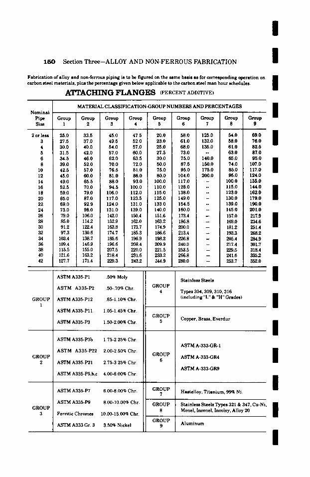
I
150 Section Three-ALLOY AND NON-FERROUS FABRICATION /
Fabrication of alloy and non-ferrous piping is to be figured on the same basis as for corresponding operation on carbon steel materials, plus the percentage given below applicable to the carbon steel man hour schedules. |
AI~I~ACHING F L A N G E S (PERCENT ADDITIVE)
MATERIAL CLASSIFICATION-GROUP NUMBERS AND PERCENTAGES Nominal r
Pipe Group Group Group G r o u p G r o u p Group Group Group Group Size 1 2 3 4 i 5 6 7 8 9
2 or less 25.0 33.5 45.0 47.5 ! 20.0 58.0 125.0 54.0 69.0 3 27.5 37.0 49.5 52.0 23.0 61.0 132.0 58.0 76.0 4 30.0 40.0 54.0 57.0 25.0 68.0 135.0 61.0 82.5 5 31.5 42.0 57.0 60.0 27.5 73.0 -- 63.0 87.0 6 34.5 46.0 62.0 63.5 30.0 75.0 140.0 65.0 95.0 8 39.0 52.0 70.0 72.0 50.0 87.5 150.0 74.0 107.0
10 42.5 57.0 76.5 81.0 75.0 95.0 175.0 85.0 117.0 12 45.0 60.0 81.0 86.0 80.0 104.0 200.0 95.0 124.0 14 49.0 65.5 88.0 93.0 I00.0 117.0 - I00.0 135.0 16 52.5 70.0 94.5 100.0 110.0 128.0 - 115.0 144.0 18 59.0 79.0 106.0 112.0 115.0 138.0 - 123.0 162.0 20 65.0 87.0 117.0 123.5 125.0 149.0 - 130.0 179.0 22 69.0 92.9 124.0 131.0 133.0 154.5 - 139.0 190.0 24 73.0 98.0 131.0 139.0 140.0 160.0 -- 145.0 201.0 26 79.0 106.0 142.0 150.4 ; 151.6 173.4 -- 157.0 217.9 28 85.0 114.2 152.9 162.0 163.2 186.8 -- 169.0 234.6 30 91.2 122.4 163.8 173.7 174.9 200.0 -- 181.2 251.4 32 97.3 130.6 174.7 185.3 186.6 213.4 -- 193.3 268.2 34 103.4 138.7 185.6 196.9 i 198.2 226.8 - 205.4 284.9 36 109.4 146.9 196.6 208.4 209.9 240.0 - 217.4 301.7 38 115.5 155.0 207.5 220.0 221.5 253.5 -- 229.5 318.4 40 121.6 163.2 218.4 231.6 233.2 266.8 -- 241.6 3352 42 127.7 171.4 229.3 243.2 244.9 280.0 -- 253.7 352.0
ASTM A335-PI .50% Moly Stainless Steels
I I I I I I I
GROUP I
GROUP 2
GROUP 3
ASTM A335-P2 .50-.70% Chr.
ASTM A335-PI2 .85- I.I0~- Chr.
ASTM A335-PI I 1.05-1.45~ Chr.
ASTM A335-P3 1.50-2.00% Chr.
ASTM A335-P3b 1.75-2.25% Chr.
ASTM A335-P22 2.00-2.50~ Chr.
ASTM A335-P21 2.75-3.25% Chr.
ASTM A335-P5,b,c 4.00-6.00% Chr.
ASTM A335-P7 6.00-8.00% Chr.
ASTM A335-P9 8.00-I0.00~ Chr.
Ferritic Chromes 10.00-15.00% Chr.
ASTM A333 Gr. 3 3.50% Nickel
GROUP 4
GROUP 5
GROUP 6
GROUP 7
GROUP 8
GROUP
Types 304,309, 310,316 (including "L" & "H" Grades)
Copper, Brass, Everdur
ASTM A-333-GR- 1
ASTM A-333-GR4
ASTM A-333-GR9
Hastelloy, Titanium, 99% Ni.
Stainless Steels Types 321 & 347, Cu-Ni Monel, Inconel, lncoloy, Alloy 20
Aluminum
/
/
/
/ /
/

I I Section Three--ALLOY AND NON-FERROUS FABRICATION 1 5 1
Fabricat ion of alloy and non-ferrous piping is to be figured on the same basis as for corresponding operation on carbon steel mater ia ls , plus the percentage given below applicable to the carbon steel m a n hour schedules.
I M A K E - O N S T H R O U G H 12-IN.
H A N D L E VALVES T H R O U G H 42-IN.
PERCENT ADDITIVE
/ MATERIAL CLASSIFICATION-GROUP NUMBERS AND PERCENTAGES
No ! I I i Size Group Group Group Group Group Group Group Group Group Inches 1 | 2 | 3 [ 4 5 6 7 8 9
I 114 318 112 314
I 1-1/4 1-1/2 2 2-I/2
3-1/2 4 6 8
10 12 14
20
26 28
32 34 36 38 / ~ 42
/
17.0 7.0 21.0 45.0 20.0 25.0 19.0 8.0 23.0 50.0 22.0 28.0 21.0 9.0 26.0 56.0 24.0 31.0 23.0 10.0 29.0 62.0 27.0 34.0 26.0 11.0 32.0 69.0 30.0 38.0 29.0 12.0 36.0 76.5 33.0 42.0 32.0 13.5 40.0 85.0 37.0 47.0 36.0 15.0 44.0 94.0 41.0 52.0 37.5 16.0 45.5 97.0 42.5 55.0 39.0 17.0 46.0 99.0 44.0 57.0 42.0 18.0 49.5 100.0 45.0 60.5 43.0 19.0 51.0 101.0 46.0 62.0 45.5 19.4 55.3 105.0 51.4 66.0 60.7 25.9 73.8 140.0 68.6 88.0 75.9 I 32.4 92.2 175.0 85.7 110.0 91.1 38.9 110.6 210.0 102.8 132.0
106.3 45.4 129.0 -- 120.0 154.0 121.4 51.8 147.5 -- 137.0 176.0 136.6 58.3 166.0 -- 154.3 198.0 151.8 64.8 184.4 -- 171.4 220.0 167.0 71.3 202.8 -- 188.5 242.0 182.2 77.8 221.3 I 205.7 264.0 i m
197.3 84.2 239.7 -- 222.8 286.0 212.5 90.7 258.2 -- 240.0 308.0 227.7 97.2 276.6 -- 257.0 330.0 242.9 103.7 295.0 -- 274.2 352.0 258.1 110.2 313.5 -- 291.4 374.0 273.2 116.6 331.9 -- 308.5 396.0 288.4 123.0 350.4 -- 325.6 418.0 303.6 129.6 368.8 -- 342.8 440.0 318.8 136.0 387.2 -- 359.9 462.0
(table continued on next page)
I
I
I
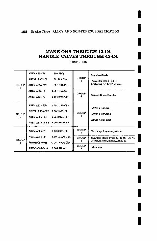
/
1 5 2 Section Three-ALLOY AND NON-FERROUS FABRICATION
M A K E - O N S T H R O U G H 12-IN. H A N D L E VALVES T H R O U G H 42-IN.
(CONTINUED)
/
/
/
/
GROUP 1
GROUP 2
GROUP 3
ASTM A335-PI .50% Moly
ASTM A335-P2 .50-.70% Chr.
ASTM A335-PI2 .85-1.10% Chr.
ASTM A335-PI I 1.05-1.45% Chr.
ASTM A335-P3 1.50-2.00~ Chr.
ASTM A335-P3b 1.75-2.25% Chr.
ASTM A335-P22 2.00-2.50% Chr.
ASTM A335-P21 2.75-3.25% Chr.
ASTM A335-P5,b,c 4.00-6.0(00 Chr.
ASTM A335-P7 6.00-8.00~ Chr.
ASTM A335-P9 8.00-10.00~ Chr.
Ferritic Chromes 10.00-15.00% Chr.
ASTM A333 Gr. 3 3.50% Nickel
GROUP 4
GROUP 5
GROUP 6
GROUP 7
GROUP 8
GROUP
Stainless Steels
Types 304, 309, 310,316 (including "L" & "H" Grades)
Copper, Brass, Everdur
ASTM A-333-GR- 1
ASTM A-333-GR4
ASTM A-333-GR9
Hastelloy, Titanium, 99~ Ni.
Stainless Steels Types 321 & 347, Cu-Ni Monel, Inconel, Incoloy, Alloy 20
Aluminum
I
I
I I I I
I
I
I I
I
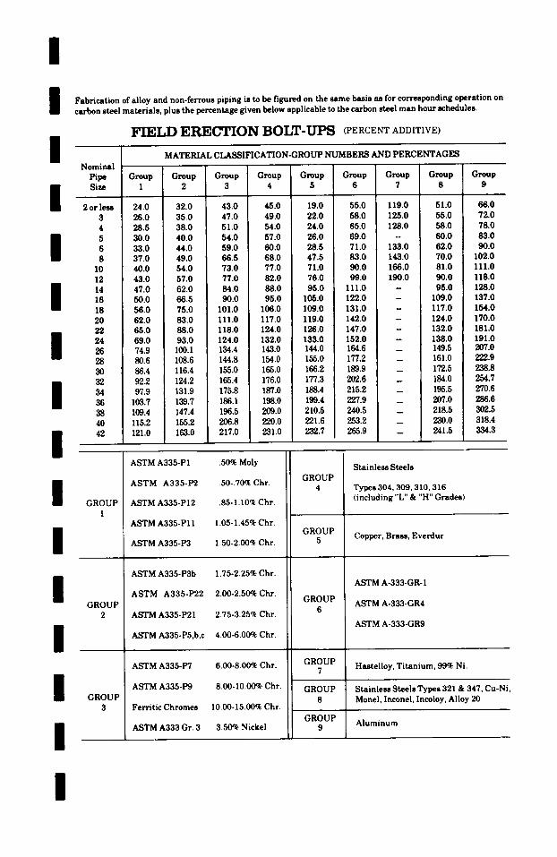
/ Fabrication of and non-ferrous piping is to be figured on the same basis as for corresponding operation on alloy carbon steel materials, plus the percentage given below applicable to the carbon steel man hour schedules.
FIELD ERECTION BOLT-UPS (PERCENT ADDITIVE) / Nominal [L
Pipe Group Group Group ! Group Group Group Group Group Group Size 1 2 3 4 5 6 7 8 9
2 or leas 24.0 32.0 43.0 45.0 19.0 55.0 119.0 51.0 66.0 3 26.0 35.0 47.0 49.0 22.0 58.0 125.0 55.0 72.0 4 28.5 38.0 51.0 54.0 24.0 65.0 1 28.0 58.0 78.0 5 30.0 40.0 54.0 57.0 26.0 69.0 -- 60.0 83.0 6 33.0 44.0 59.0 60.0 28.5 71.0 133.0 62.0 90.0 8 37.0 49.0 66.5 68.0 47.5 83.0 143.0 70.0 102.0
10 40.0 54.0 73.0 77.0 71.0 90.0 166.0 81.0 111.0 12 43.0 57.0 77.0 82.0 76.0 99.0 190.0 90.0 118.0
l 14 47.0 62.0 84.0 88.0 95.0 111.0 - 95.0 128.0 16 50.0 66.5 90.0 95.0 105.0 122.0 - 109.0 137.0 18 56.0 75.0 101.0 106.0 109.0 131.0 - 117.0 154.0 20 62.0 83.0 111.0 117.0 119.0 142.0 - 124.0 170.0 22 65.0 88.0 118.0 124.0 126.0 147.0 - 132.0 181.0 24 69.0 93.0 124.0 132.0 133.0 152.0 - 138.0 191.0 26 74.9 100.1 134.4 143.0 144.0 164.6 _ 149.5 207.0 28 80.6 108.6 144.8 154.0 155.0 177.2 _ 161.0 222.9 30 86.4 116.4 155.0 165.0 166.2 189.9 _ 172.5 238.8 32 92.2 124.2 165.4 176.0 177.3 202.6 _ 184.0 254.7 34 97.9 131.9 175.8 187.0 188.4 215.2 _ 195.5 270.6 36 103.7 139.7 186.1 198.0 199.4 227.9 _ 207.0 286.6 38 109.4 147.4 196.5 209.0 210.5 240.5 _ 218.5 302.5 40 115.2 155.2 206.8 220.0 221.6 253.2 _ 230.0 318.4 42 121.0 163.0 217.0 231.0 232.7 265.9 _ 241.5 334.3
h
i ' 1
/
l /
/
/
/
GROUP 1
GROUP 2
GROUP 3
MATERIAL CLASSIFICATION-GROUP NUMBERS AND PERCENTAGES
ASTM A335-PI .50% Moly
ASTM A335-P2 .50-.70% Chr.
ASTM A335-PI2 .85-1.10% Chr.
ASTM A335-PI 1 1.05-1.45% Chr.
ASTM A335-P3 1.50-2.00% Chr.
ASTM A335-P3b 1.75-2.25% Chr.
ASTM A335-P22 2.00-2.50% Chr.
ASTM A335-P21 2.75-3.25% Chr.
ASTM A335-P5,b,c 4.00-6.00% Chr.
ASTM A335-P7 6.00-8.00% Chr.
ASTM A335-P9 8.00-10.00% Chr.
Ferritic Chromes I0.00-15.00% Chr.
ASTM A333 Gr. 3 3.50~ Nickel
GROUP 4
GROUP 5
GROUP 6
GROUP 7
GROUP 8
GROUP 9
Stainless Steels
Types 304,309,310,316 (including "L" & "H" Grades)
Copper, Brass, Everdur
ASTM A-333-GR- 1
ASTM A-333-GR4
ASTM A-333-GR9
Hastelloy, Titanium, 99% Ni.
Stainless Steels Types 321 & 347, Cu-Ni, Monel, Inconel, Incoloy, Alloy 20
Aluminum
/
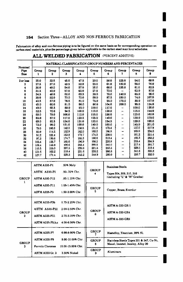
/
154 Section Three-ALLOY AND NON-FERROUS FABRICATION
Fabrication of alloy and non-ferrous piping is to be figured on the same basis as for corresponding operation on carbon steel materials, plus the percentage given below applicable to the carbon steel man hour schedules.
ALL W E L D E D F A B R I C A T I O N (PERCENT ADDITIVE)
I I
MATERIAL CIASSIFICATION-GROUP NUMBERS AND PERCENTAGES Nominal !
Pipe Group Group Group Group Group Group Group Group Size I 2 3 4 5 6 7 8
/ Group
9 �9 . . �9 l �9 n
i 2 or less 25.0 33.5 45.0 47.5 20.0 58.0 125.0 54.0 69.0 3 27.5 37.0 49.5 52.0 23.0 61.0 132.0 58.0 76.0 4 30.0 40.0 54.0 57.0 25.0 68.0 135.0 61.0 82.5
i
5 31.5 42.0 57.0 60.0 27.5 73.0 - 63.0 87.0 6 34.5 46.0 62.0 63.5 30.0 75.0 140.0 65.0 95.0 i 8 39.0 52.0 70.0 72.0 50.0 87.5 150.0 74.0 107.0 /
10 42.5 57.0 76.5 I 81.0 75.0 95.0 175.0 85.0 117.0 12 45.0 60.0 81.0 86.0 80.0 104.0 200.0 95.0 124.0 14 49.0 65.5 88.0 93.0 100.0 117.0 - 100.0 135.0 16 52.5 70.0 94.5 I00.0 1 I0.0 128.0 - 115.0 144.0 i 18 59.0 79.0 106.0 112.0 115.0 138.0 123.0 162.0 $ 20 65.0 87.0 117.0 123.5 125.0 149.0 i - i - 130.0 179.0 22 69.0 92.5 124.0 131.0 133.0 154.5 - 139.0 190.0 24 73.0 98.0 131.0 139.0 140.0 160.0 -- 145.0 201.0 26 79.0 106.0 142.0 150.5 151.6 173.4 -- 157.0 217.9 B 28 85.0 114.2 152.9 162.0 163.2 186.8 - 169.0 234.6 = 30 ] 91.2 122.4 163.8 173.7 174.9 200.0 - 181.2 251.4 32 97.3 130.6 174.7 185.3 186.6 213.4 - 193.3 268.2 34 103.4 138.7 185.6 196.9 198.2 226.8 - 205.4 284.9 36 109.4 146.9 196.6 208.4 209.9 240.0 -- 217.4 301.7 i 38 115.5 155.0 207.5 : 220.0 221.5 253.5 -- , 229.5 318.4 m 40 121.6 163"2 218.4 231.6 233.2 266.8 -- 241.6 335.2 42 127.7 171.4 229.3 243.2 244.9 280.0 -- 253.7 352.0
GROUP I
GROUP 2
ASTM A335-PI .50~ Moly
ASTM A335-P2 .50-.70% Chr.
ASTM A335-PI2 85-1.10% Chr.
ASTM A335-PI I 1.05- 1.45% Chr.
ASTM A335-P3 1.50-2.00% Chr.
ASTM A335-P3b 1.75-2.25% Chr.
ASTM A335-P22 2.00-2.50% Chr.
ASTM A335-P21 2.75-3.25% Chr.
ASTM A335-P5,b,c 4.00-6.00% Chr.
ASTM A335-P7 6.00-8.00% Chr.
ASTM A335-P9 8.00-10.00% Chr.
Ferritic Chromes 10.00-15.00% Chr.
ASTM A333 Gr. 3 3.50% Nickel
GROUP 4
GROUP 5
GROUP 6
GROUP 7
Stainless Steels I
Types 304,309, 310,316 i (including "L" & "H" Grades) I Copper, Brass, Everdur
ASTM A-333-GR-I
ASTM A-333-GR4
ASTM A-333-GR9
GROUP 8
GROUP 9
Hutel loy, Titanium, 99% Ni.
/
/
GROUP 3
I
I Aluminum
m Stainless Steels Types 321 & 347, Cu-Ni, i Monel, Inconel, Incoloy, Alloy 20 S
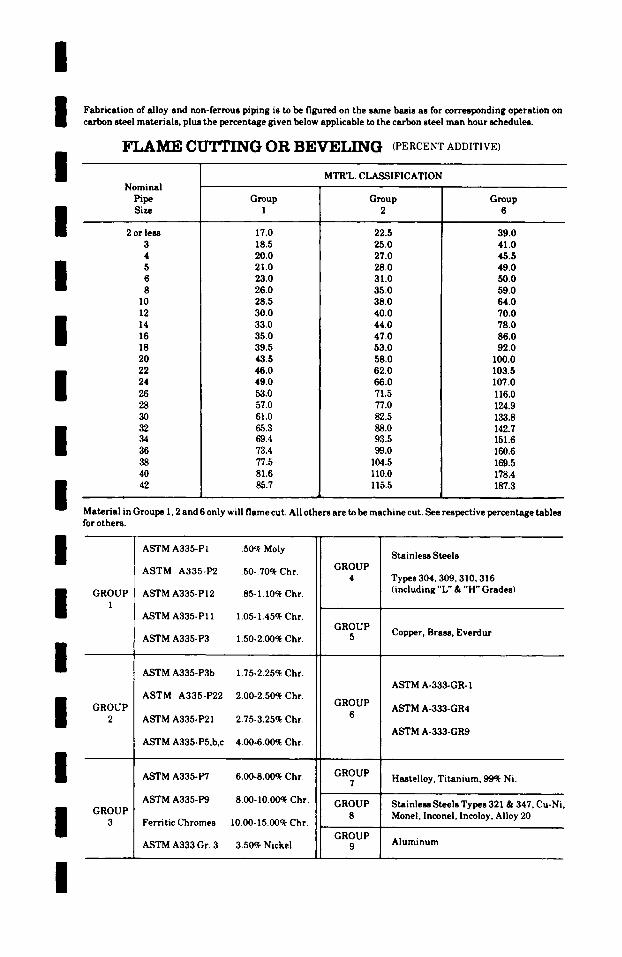
/ /
I
Fabrication of alloy and non-ferrous piping is to be figured on the same basis as/'or corresponding operation on carbon steel materials, plus the percentage given below applicable to the carbon steel man hour schedules.
FLAME CUTTING OR BEVELING (PERCENT ADDITIVE)
MTR'L. CLASSIFICATION
I I I I I /
Nominal Pipe Size
2 or less 3 4 5 6 8
I0 12 14 16 18 20 22 24 26 28 3O 32 34 36 38 40 42
Group 1
17.0 18.5 20.0 21.0 23.0 26.0 28.5 30.0 33.0 35.0 39.5 43.5 46.0 49.0 53.0 57.0 61.0 65.3 69.4 73.4 77.5 81.6 85.7
Group 2
22.5 25.0 27.0 28.0 31.0 35.0 38.0 40.0 44.0 47.0 53.0 58.0 62.0 66.0 71.5 77.0 82.5 88.0 93.5 99.0
104.5 110.0 115.5
Group 6
39.0 41.0 45.5 49.0 50.0 59.0 64.0 70.0 78.0 86.0 92.0
I00.0 103.5 107.0 116.0 124.9 133.8 142.7 151.6 160.6 169.5 178.4 187.3
Material in Groups 1, 2 and 6 only will flame cut. All others are to be machine cut. See respective percentage tables
I I I I I I
for others.
GROUP 1
GROUP 2
GROUP 3
ASTM A335-P1 .50~ Moly
ASTM A335-P2 .50-.70% Chr.
ASTM A335-P12 .85-1.10% Chr.
ASTM A335-P11 1.05-1.45% Chr.
ASTM A335-P3 1.50-2.00% Chr.
ASTM A335-P3b 1.75-2.25% Chr.
ASTM A335-P22 2.00-2.50% Chr.
ASTM A335-P21 2.75-3.25% Chr.
ASTM A335-P5,b,c 4.00-6.00% Chr.
ASTM A335-P7 6.00-8.00% Chr.
ASTM A335-P9 8.00-10.00% Chr.
Ferritic Chromes 10.00-15.00% Chr.
ASTM A333 Gr. 3 3.50% Nickel
GROUP 4
GROUP 5
GROUP 6
GROUP 7
GROUP 8
GROUP 9
Stainless Steels
Types 304,309, 310,316 (including "L" & "H" Grades)
Copper, Brass, Everdur
ASTM A-333-GR- 1
ASTM A-333-GR4
ASTM A-333-GR9
Hastelloy, Titanium, 99~ Ni.
Stainless Steels Types 321 & 347, Cu-Ni Monel, Inconel, Incoloy, Alloy 20
Aluminum
I
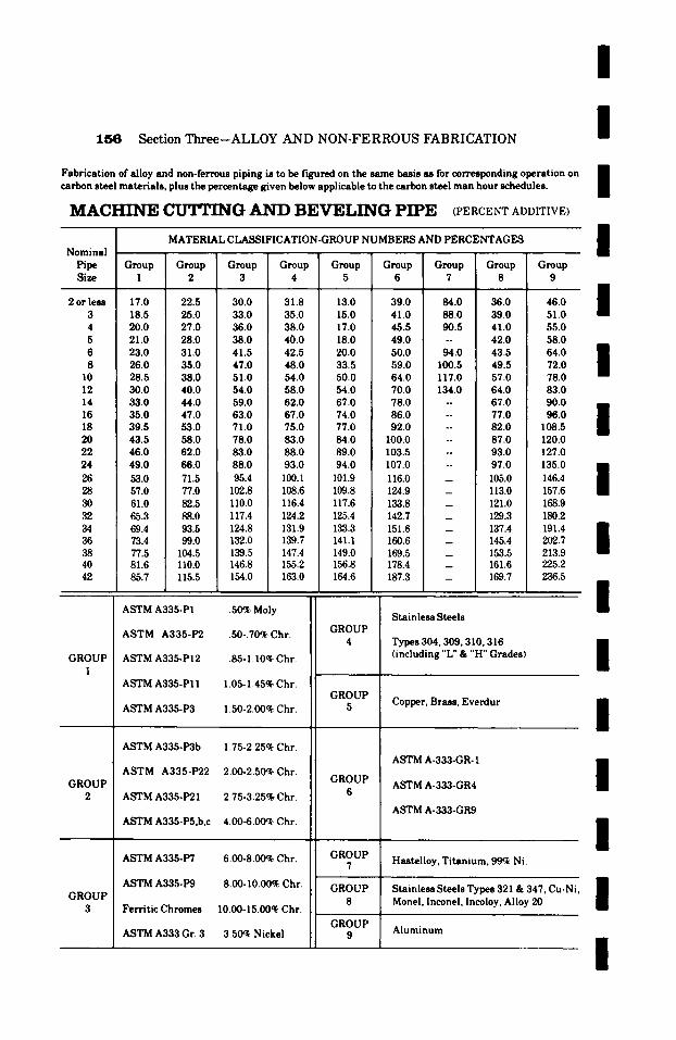
/
1 5 6 Section Three--ALLOY AND NON-FERROUS FABRICATION
Fabrication of alloy and non-ferrous piping is to be f'~ured on the same basis as for corresponding operation on carbon steel materials, plus the percentage given below applicable to the carbon steel man hour schedules.
M A C H I N E C U T T I N G A N D B E V E L I N G P I P E (PERCENT ADDITIVE)
/ / m
MATERIAL CLASSIFICATION-GROUP NUMBERS AND PERCENTAGES I Nominal Pipe Group Group Group Group Group Group Group Group Group Size 1 2 3 4 5 6 7 8 9
m
2 or less 17.0 22.5 30.0 31.8 13.0 39.0 84.0 36.0 46.0 / m 3 18.5 25.0 33.0 35.0 15.0 41.0 88.0 39.0 51.0
4 20.0 27.0 36.0 38.0 17.0 45.5 90.5 41.0 55.0 5 21.0 28.0 38.0 40.0 18.0 49.0 -- 42.0 58.0
m
6 23.0 31.0 41.5 42.5 20.0 50.0 94.0 43.5 64.0
$ 8 26.0 35.0 47.0 48.0 33.5 59.0 100.5 49.5 72.0 10 28.5 38.0 51.0 54.0 50.0 64.0 117.0 57.0 78.0 12 30.0 40.0 54.0 58.0 54.0 70.0 134.0 64.0 83.0 14 33.0 44.0 59.0 62.0 67.0 78.0 -- 67.0 90.0 mm 16 35.0 47.0 63.0 67.0 74.0 86.0 -- 77.0 96.0 18 39.5 53.0 71.0 75.0 77.0 92.0 -- 82.0 108.5 | 20 43.5 58.0 78.0 83.0 84.0 100.0 -- 87.0 120.0 22 46.0 62.0 83.0 88.0 89.0 103.5 -- 93.0 127.0 24 49.0 66.0 88.0 93.0 94.0 107.0 -- 97.0 135.0 mm
$ 26 53.0 71.5 95.4 100.1 101.9 116.0 -- 105.0 146.4 28 57.0 77.0 102.8 108.6 109.8 124.9 -- 113.0 157.6 30 61.0 82.5 110.0 116.4 117.6 133.8 -- 121.0 168.9 32 65.3 88.0 117.4 124.2 125.4 142.7 -- 129.3 180.2 34 69.4 93.5 124.8 131.9 133.3 151.6 -- 137.4 191.4 n 36 73.4 99.0 132.0 139.7 141.1 160.6 -- 145.4 202.7 $ 38 77.5 104.5 139.5 147.4 149.0 169.5 153.5 213.9 40 81.6 110.0 146.8 155.2 156.8 178.4 -- 161.6 225.2 42 85.7 115.5 154.0 163.0 164.6 187.3 -- 169.7 236.5
1 GROUP
1
GROUP 2
GROUP 3
ASTM A335-PI .50% Moly
ASTM A335-P2 .50-.70% Chr.
ASTM A335-P12 .85-1.10~ Chr.
ASTM A335-PI 1 1.05-1.45% Chr.
ASTM A335-P3 1.50-2.00% Chr.
ASTM A335-P3b 1.75-2.25% Chr.
ASTM A335-P22 2.00-2.50% Chr.
ASTM A335-P21 2.75-3.25% Chr.
ASTM A335-P5,b,c 4.00-6.00~ Chr.
ASTM A335-P7 6.00-8.00% Chr.
ASTM A335-P9 8.00-10.00~ Chr.
Ferritic Chromes I0.00-15.00q~ Chr.
ASTM A333 Gr. 3 3.50~ Nickel
GROUP 4
GROUP 5
GROUP 6
GROUP 7
Stainless Steels
Types 304,309, 310,316 (including "L" & "H" Grades)
Copper, Brass, Everdur
ASTM A-333-GR- 1
ASTM A-333-GR4
ASTM A-333-GR9
Hastelloy, Titanium, 99~ Ni.
GROUP 8
GROUP 9
Stainless Steels Types 321 & 347, Cu-Ni, Monel, Inconel, Incoloy, Alloy 20
Aluminum
/
/
/
I
I /
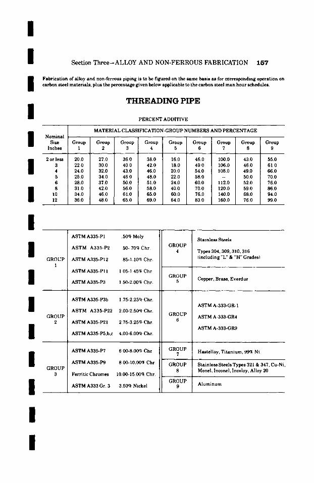
I / / /
Section Three-ALLOY AND NON-FERROUS FABRICATION 157
Fabrication of alloy and non-ferrous piping is to be figured on the same basis as for corresponding operation on carbon steel materials, plus the percentage given below applicable to the carbon steel man hour schedules.
T H R E A D I N G PIPE
PERCENT ADDITIVE
I I I I
Nominal Size
Inches
2 or leas 3 4 5 6 8
10 12
MATERIAL CLASSIFICATION-GROUP NUMBERS AND PERCENTAGE
Group Group Group Group Group Group Group Group Group 1 2 3 4 5 6 7 8 9
20.0 27.0 36.0 38.0 16.0 46.0 100.0 43.0 55.0 22.0 30.0 40.0 42.0 18.0 49.0 106.0 46.0 61.0 24.0 32.0 43.0 46.0 20.0 54.0 108.0 49.0 66.0 25.0 34.0 46.0 48.0 22.0 58.0 -- 50.0 70.0 28.0 37.0 50.0 51.0 24.0 60.0 112.0 52.0 76.0 31.0 42.0 56.0 58.0 40.0 70.0 120.0 59.0 86.0 34.0 46.0 61.0 65.0 60.0 76.0 140.0 68.0 94.0 36.0 48.0 65.0 69.0 64.0 83.0 160.0 76.0 99.0
I I I I I I
GROUP 1
GROUP 2
GROUP 3
ASTM A335-PI .50~ Moly
ASTM A335-P2 .50-.70ck Chr.
ASTM A335-P12 .85-1.10ck Chr.
ASTM A335-PI 1 1.05-1.45ck Chr.
ASTM A335-P3 1.50-2.00~ Chr.
ASTM A335-P3b 1.75-2.25ck Chr.
ASTM A335-P22 2.00-2.50ck Chr.
ASTM A335-P21 2.75-3.25ck Chr.
ASTM A335-P5,b,c 4.00-6.00% Chr.
ASTM A335-P7 6.00-8.00ck Chr.
ASTM A335-P9 8.00- I0.0(~ Chr.
Ferritic Chromes I0.00-15.00~ Chr.
ASTM A333 Gr. 3 3.50~ Nickel
GROUP 4
GROUP 5
GROUP 6
GROUP 7
GROUP 8
GROUP 9
Stainless Steels
Types 304,309, 310, 316 (including "L" & "H" Grades)
Copper, Brass, Everdur
ASTM A-333-GR- 1
ASTM A-333-GR4
ASTM A-333-GR9
Hastelloy, Titanium, 99~ Ni.
Stainless Steels Types 321 & 347, Cu-Ni Monel, Inconel, Incoloy, Alloy 20
Aluminum
/
/
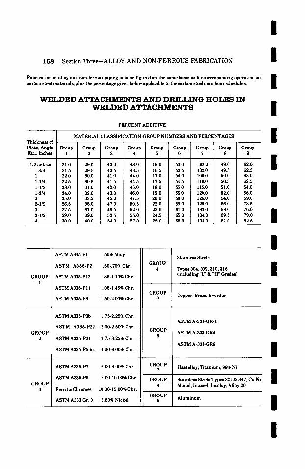
158 Section Three-ALLOY AND NON-FERROUS FABRICATION
Fabrication of alloy and non-ferrous piping is to be f~gured on the same basis as for corresponding operation on carbon steel materials, plus the percentage given below applicable to the carbon steel man hour schedules.
WELDED ATTACHMENTS A N D D ~ G HOLES IN WELDED A~'rACHMENTS
PERCENT ADDITIVE
Thickness of Plate, Angle Etc., Inches
1/2 or less 3/4
1 1-1/4 1-1/2 1-3/4 2 2-1/2 3 3-1/2 4
MATERIAL CLASSIFICATION-GROUP NUMBERS AND PERCENTAGES
/
l / / /
Group Group Group Group Group Group Group Group Group 1 2 3 4 5 6 7 8 9
i 21.0 29.0 40.0 43.0 16.0 53.0 98.0 49.0 62.0 1
/ 21.5 29.5 40.5 43.5 16.5 53.5 102.0 49.5 62.5 22.0 30.0 41.0 44.0 17.0 54.0 106.0 50.0 63.0 22.5 30.5 41.5 44.5 17.5 54.5 110.0 50.5 63.5 i 23.0 31.0 42.0 45.0 18.0 55.0 115.0 51.0 64.0 l 24.0 32.0 43.0 46.0 19.0 56.0 120.0 52.0 66.0 m 25.0 33.5 45.0 47.5 20.0 58.0 125.0 54.0 69.0 26.5 35.0 47.0 50.5 22.0 59.0 129.0 56.0 73.5 27.5 37.0 49.5 52.0 23.0 61.0 132.0 58.0 76.0 I l l 29.0 39.0 52.5 55.0 24.5 65.0 134.0 59.5 79.0 1 30.0 40.0 54.0 57.0 25.0 68.0 135.0 61.0 82.5
/
GROUP 1
GROUP 2
GROUP 3
ASTM A335-PI .50% Moly
ASTM A335-P2 .50-.70% Chr.
ASTM A335-P12 .85-1.10% Chr.
ASTM A335-PI 1 1.05-1.45% Chr.
ASTM A335-P3 1.50-2.00% Chr.
ASTM A335-P3b 1.75-2.25% Chr.
ASTM A335-P22 2.00-2.50% Chr.
ASTM A335-P21 2.75-3.25% Chr.
ASTM A335-P5,b,c 4.00-6.00% Chr.
ASTM A335-P7 6.00-8.00% Chr.
ASTM A335-P9 8.00-10.00% Chr.
Ferritic Chromes I0.00-15.00% Chr.
ASTM A333 Gr. 3 3.50% Nickel
GROUP 4
GROUP 5
GROUP 6
GROUP 7
GROUP 8
GROUP
Stainless Steels
Types 304,309, 310,316 (including "L" & "H" Grades)
Copper, Brass, Everdur
ASTM A-333-GR- 1
ASTM A-333-GR4
ASTM A-333-GR9
Hastelloy, Titanium, 99% Ni.
Stainless Steels Types 321 & 347, Cu-Ni Monel, Inconel, Incoloy, Alloy 20
Aluminum
l /
l / /
l /
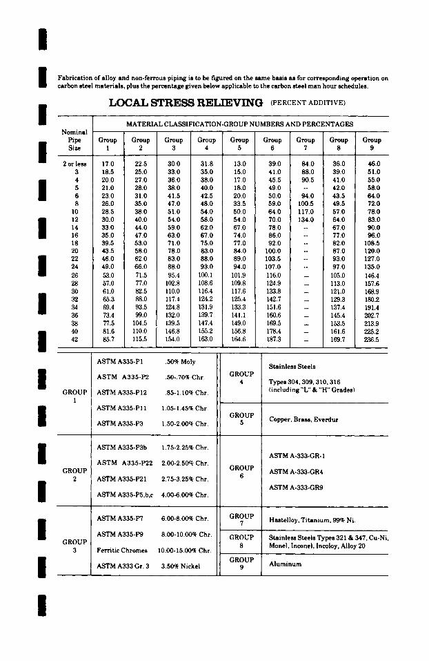
/
I /
Fabrication of alloy and non-ferrous piping is to be figured on the same basis as for corresponding operation on carbon steel materials, plus the percentage given below applicable to the carbon steel man hour schedules.
LOCAL STRESS RELIEVING (PERCENT ADDITIVE)
I I I I I I
MATERIAL CLASSIFICATION-GROUP NUMBERS AND PERCENTAGES Nominal
Pipe Group Group Group Group Group Group Group Group Group Size 1 2 3 4 5 6 7 8 9
2 or less 17.0 22.5 30.0 31.8 13.0 39.0 84.0 36.0 46.0 3 18.5 25.0 33.0 35.0 15.0 41.0 88.0 39.0 51.0 4 20.0 27.0 36.0 38.0 17.0 45.5 90.5 41.0 55.0 5 21.0 28.0 38.0 40.0 18.0 49.0 -- 42.0 58.0 6 23.0 31.0 41.5 42.5 20.0 50.0 94.0 43.5 64.0 8 26.0 35.0 47.0 48.0 33.5 59.0 100.5 49.5 72.0
10 28.5 38.0 51.0 54.0 50.0 64.0 117.0 57.0 78.0 12 30.0 40.0 54.0 58.0 54.0 70.0 134.0 64.0 83.0 14 33.0 44.0 59.0 62.0 67.0 78.0 -- 67.0 90.0 16 35.0 47.0 63.0 67.0 74.0 86.0 -- 77.0 96.0 18 39.5 53.0 71.0 75.0 77.0 92.0 -- 82.0 108.5 20 43.5 58.0 78.0 83.0 84.0 I00.0 -- 87.0 120.0 22 46.0 62.0 83.0 88.0 89.0 103.5 -- 93.0 127.0 24 49.0 66.0 88.0 93.0 94.0 107.0 -- 97.0 135.0 26 53.0 71.5 95.4 100.1 101.9 116.0 -- 105.0 146.4 28 57.0 77.0 102.8 108.6 109.8 124.9 -- 113.0 157.6 30 61.0 82.5 110.0 116.4 117.6 133.8 -- 121.0 168.9 32 65.3 88.0 117.4 124.2 125.4 142.7 -- 129.3 180.2 34 69.4 93.5 124.8 131.9 133.3 151.6 -- 137.4 191.4 36 73.4 99.0 132.0 139.7 141.1 160.6 - 145.4 202.7 38 77.5 104.5 139.5 147.4 149.0 169.5 -- 153.5 213.9 40 81.6 110.0 146.8 155.2 156.8 178.4 -- 161.6 225.2 42 85.7 115.5 154.0 163.0 164.6 187.3 -- 169.7 236.5
I I I I I I
GROUP 1
GROUP 2
GROUP 3
ASTM A335-PI .50% Moly
ASTM A335-P2 .50-.70% Chr.
ASTM A335-P12 .85-1.10% Chr.
ASTM A335-PI 1 1.05-1.45% Chr.
ASTM A335-P3 1.50-2.00ck Chr.
ASTM A335-P3b 1.75-2.25% Chr.
ASTM A335-P22 2.00-2.50~ Chr.
ASTM A335-P21 2.75-3.25q~ Chr.
ASTM A335-P5,b,c 4.00-6.00% Chr.
ASTM A335-P7 6.00-8.00~ Chr.
ASTM A335-P9 8.00-I0.00~ Chr.
Ferritic Chromes 10.00-15.00q~ Chr.
ASTM A333 Gr. 3 3.50% Nickel
GROUP 4
GROUP 5
GROUP 6
GROUP 7
GROUP 8
GROUP 9
Stainless Steels
Types 304,309, 310,316 (including "L" & "H" Grades)
Copper, Brass, Everdur
ASTM A-333-GR- I
ASTM A-333-GR4
ASTM A-333-GR9
Hastelloy, Titanium, 99% Ni.
Stainless Steels Types 321 & 347, Cu-Ni, Monel, Inconel, Incoloy, Alloy 20
Aluminum
/
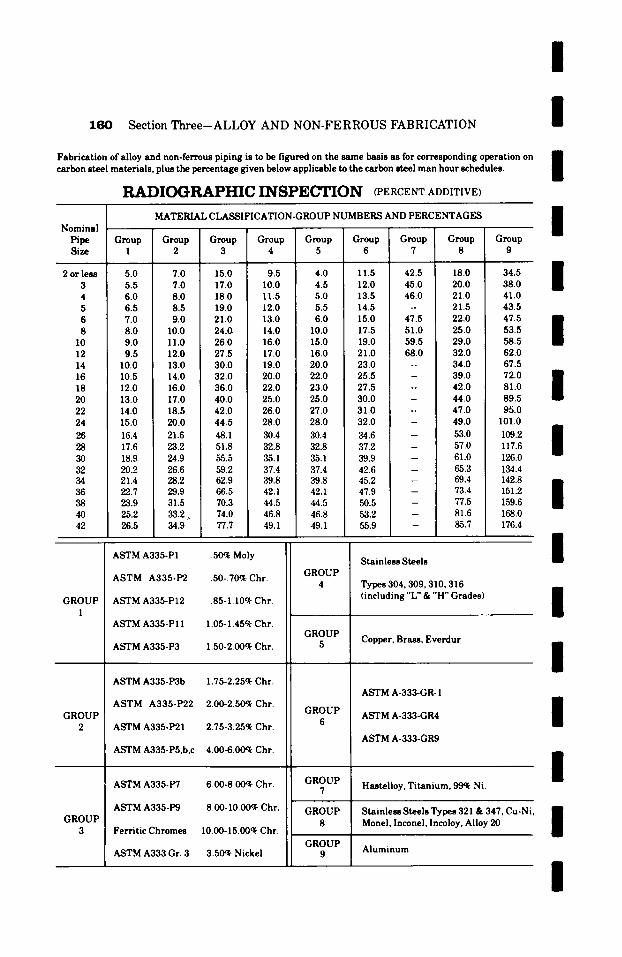
160 Section Three-ALLOY AND NON-FERROUS FABRICATION
Fabrication of alloy and non-ferrous piping is to be figured on the same basis as for corresponding operation on carbon steel materials, plus the percentage given below applicable to the carbon steel man hour schedules.
RADIOGRAPI~C INSPECTION (PERCENT ADDITIVE)
/ /
I MATERIAL CIJuSSIFICATION-GROUP NUMBERS AND PERCENTAGES
Nominal Pipe Group Group Group Group Group Group Group Group Group Size I 2 3 4 5 6 7 : 8 9
I i
2 or less 5.0 7.0 15.0 9.5 4.0 I 1.5 42.5 18.0 34.5 i 3 5.5 7.0 17.0 I0.0 4.5 12.0 45.0 20.0 38.0 m 4 6.0 8.0 18.0 11.5 5.0 13.5 46.0 21.0 41.0 5 6.5 8.5 19.0 12.0 5.5 14.5 -- 21.5 43.5 6 7.0 9.0 21.0 13.0 6.0 15.0 47.5 22.0 47.5 i 8 8.0 I0.0 24.0 14.0 I0.0 17.5 51.0 25.0 53.5 l
10 9.0 11.0 26.0 16.0 15.0 19.0 59.5 29.0 58.5 12 9.5 12.0 27.5 17.0 16.0 21.0 68.0 32.0 62.0 14 10.0 13.0 30.0 19.0 20.0 23.0 -- 34.0 67.5 16 10.5 14.0 32.0 20.0 22.0 25.5 -- 39.0 72.0 n 18 12.0 16.0 36.0 22.0 23.0 27.5 -- 42.0 81.0 $ 20 13.0 17.0 40.0 25.0 25.0 30.0 - 44.0 89.5 22 14.0 18.5 42.0 26.0 27.0 31.0 -- 47.0 95.0 24 15.0 20.0 44.5 28.0 28.0 32.0 -- 49.0 I01.0 i
26 16.4 21.6 48.1 30.4 30.4 34.6 53.0 109.2 28 17.6 23.2 51.8 32.8 32.8 37.2 57.0 117.6 m 30 18.9 24.9 55.5 35.1 35.1 39.9 61.0 126.0 32 20.2 26.6 59.2 37.4 37.4 42.6 65.3 134.4 34 21.4 28.2 62.9 39.8 39.8 45.2 69.4 142.8 mm 36 22.7 29.9 66.5 42. I 42. I 47.9 73.4 151.2 [ 38 23.9 31.5 70.3 44.5 44.5 50.5 77.5 159.6 40 25.2 33.2 .. 74.0 46.8 46.8 53.2 81.6 168.0 42 26.5 34.9 77.7 49. I 49. I 55.9 85.7 176.4
GROUP 1
GROUP 2
ASTM A335-P1 .50% Moly
ASTM A335-P2 .50-.70% Chr.
ASTM A335-P12 .85-1.10% Chr.
ASTM A335-PI 1 1.05- 1.45% Chr.
ASTM A335-P3 1.50-2.00~ Chr.
ASTM A335-P3b 1.75-2.25% Chr.
ASTM A335-P22 2.00-2.50~ Chr.
ASTM A335-P21 2.75-3.25% Chr.
ASTM A335-P5,b,c 4.00-6.00~ Chr.
ASTM A335-P7 6.00-8.00% Chr.
ASTM A335-P9 8.00-I0.00% Chr.
Ferritic Chromes I0.00-15.00% Chr.
ASTM A333 Gr. 3 3.50~ Nickel
GROUP 4
GROUP 5
GROUP 6
GROUP 7
GROUP 8
GROUP 9
Stainless Steels
Types 304,309,310,316 (including "L" & "H" Grades)
Copper, Brass, Everdur
ASTM A-333-GR- I
ASTM A-333-GR4
ASTM A-333-GR9
Hastelloy, Titanium, 99% Ni.
Stainless Steels Types 321 & 347, Cu-Ni Monel, Inconel, Incoloy, Alloy 20
Aluminum
GROUP 3
I I I I I I I
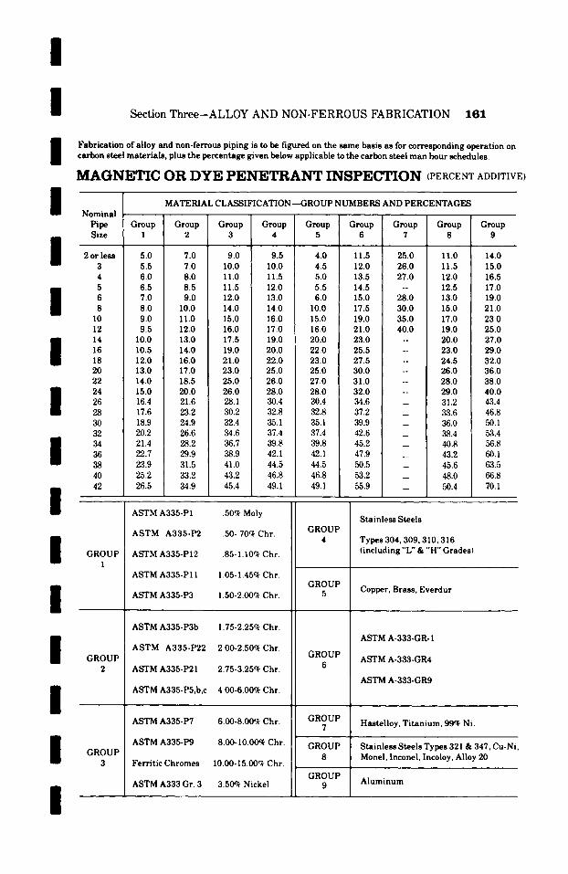
/ / / /
Section Three-ALLOY AND NON-FERROUS FABRICATION 181
Fabrication of alloy and non-ferrous piping is to be figured on the same basis as for corresponding operation on carbon steel materials, plus the percentage given below applicable to the carbon steel man hour schedules.
MAGNETIC OR DYE PENETRANT INSPE~ON (PERCENT ADDITIVE)
Nominal MATERIAL CLASSIFICATION--GROUP NUMBERS AND PERCENTAGES
Pipe Group Group Group Group Group Group Group Group Group Size 1 2 3 4 5 6 7 8 9
" .
2 or less 5.0 7.0 9.0 9.5 4.0 I 1.5 25.0 I 1.0 14.0 3 5.5 ! 7.0 10.0 10.0 4.5 12.0 26.0 11.5 15.0 4 6.0 ! 8.0 11.0 11.5 5.0 13.5 27.0 12.0 16.5
i 5 6.5 [ 8.5 11.5 12.0 5.5 14.5 -- 12.5 17.0 6 7.0 9.0 12.0 13.0 6.0 15.0 28.0 13.0 19.0 8 8.0 ~ 10.0 14.0 14.0 10.0 17.5 30.0 15.0 21.0
10 9.0 11.0 15.0 16.0 15.0 19.0 35.0 17.0 23.0 12 9.5 12.0 16.0 17.0 16.0 21.0 40.0 19.0 25.0
I 14 I0.0 13.0 17.5 19.0 20.0 23.0 -- 20.0 27.0 16 10.5 14.0 19.0 20.0 22.0 25.5 -- 23.0 29.0 18 12.0 16.0 21.0 22.0 23.0 27.5 -- 24.5 32.0 20 13.0 17.0 23.0 25.0 25.0 30.0 -- 26.0 36.0 22 14.0 18.5 25.0 26.0 27.0 31.0 -- 28.0 38.0
I 24 15.0 20.0 26.0 28.0 28.0 32.0 -- 29.0 40.0 26 16.4 21.6 28.1 30.4 30.4 34.6 31.2 43.4 28 17.6 23.2 30.2 32.8 32.8 37.2 33.6 46.8 30 18.9 24.9 32.4 35.1 35.1 39.9 36.0 50.1 32 20.2 26.6 34.6 37.4 37.4 42.6 38.4 5~3.4
I 34 21.4 28.2 36.7 39.8 39.8 45.2 40.8 56.8 36 22.7 29.9 38.9 42.1 42.1 47.9 43.2 60.1 38 23.9 31.5 41.0 44.5 44.5 50.5 45.6 63.5 40 25.2 33.2 43.2 46.8 46.8 53.2 _ 48.0 66.8
i 42 26.5 34.9 45.4 49.1 49.1 55.9 _ 50.4 70.1
I I I I I I
GROUP I
GROUP 2
GROUP 3
ASTM A335-P1 .50ck Moly
ASTM A335-P2 .50-.70ck Chr.
ASTM A335-PI2 .85-1.10~ Chr.
ASTM A335-PI I 1.05-1.45c~ Chr.
ASTM A335-P3 1.50-2.00% Chr.
ASTM A335-P3b 1.75-2.25% Chr.
ASTM A335-P22 2.00-2.50~ Chr.
ASTM A335-P21 2.75-3.25~ Chr.
ASTM A335-P5,b,c 4.00-6.00% Chr.
ASTM A335-P7 6.00-8.00~ Chr.
ASTM A335-P9 8.00-10.00~ Chr.
Ferritic Chromes I0.00-15.00c~ Chr.
ASTM A333 Gr. 3 3.50~ Nickel
GROUP 4
GROUP 5
GROUP 6
GROUP 7
GROUP 8
GROUP 9
Stainless Steels
Types 304,309, 310, 316 (including "L" & "H" Grades)
Copper, Brass, Everdur
ASTM A-333-GR- 1
ASTM A-333-GR4
ASTM A-333-GR9
Hastelloy, Titanium, 99~ Ni.
Stainless Steels Types 321 & 347. Cu-Ni Monel, Inconel, Incoloy, Alloy 20
Aluminum
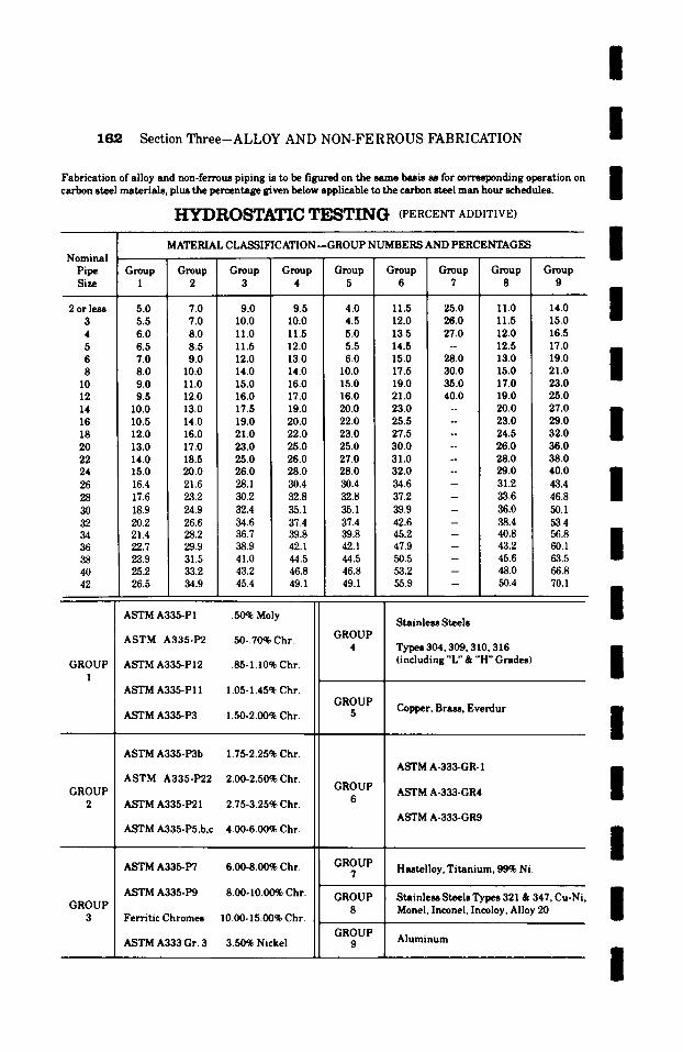
162 Section Three--ALLOY AND NON-FERROUS FABRICATION
Fabrication of alloy and non-ferrous piping is to be figured on the same basis as for corresponding operation on carbon steel materials, plus the percentage given below applicable to the carbon steel man hour schedules.
HYDROSTATIC TESTING (PERCENT ADDITIVE)
/
/
/
MATERIAL CLASSIFICATION--GROUP NUMBERS AND PERCENTAGES l Nominal - -
Pipe G r o u p Group Group Group Group Group Group Group Group Size 1 2 3 4 5 6 7 8 9
i �9 o w 1
1 2 or less 5.0 7.0 9.0 9.5 4.0 11.5 25.0 11.0 14.0 3 5.5 7.0 10.0 10.0 4.5 12.0 26.0 11.5 15.0 4 6.0 8.0 11.0 11.5 5.0 13.5 27.0 12.0 16.5 5 6.5 8.5 11.5 12.0 5.5 14.5 -- 12.5 17.0 i 6 7.0 9.0 12.0 13.0 6.0 15.0 28.0 13.0 19.0 8 8.0 10.0 14.0 14.0 10.0 17.5 30.0 15.0 21.0 |
10 9.0 11.0 15.0 16.0 15.0 19.0 35.0 17.0 23.0 12 9.5 ! 12.0 16.0 17.0 16.0 21.0 40.0 19.0 25.0 14 10.0 13.0 17.5 19.0 20.0 23.0 -- 20.0 27.0 16 10.5 14.0 19.0 20.0 22.0 25.5 - 23.0 29.0 I 18 12.0 16.0 21.0 22.0 23.0 27.5 -- 24.5 32.0 20 13.0 17.0 23.0 25.0 25.0 30.0 -- 26.0 36.0 22 14.0 18.5 25.0 26.0 27.0 31.0 -- 28.0 38.0 24 15.0 20.0 26.0 28.0 28.0 32.0 -- 29.0 ! 40.0 26 16.4 21.6 28.1 30.4 30.4 34.6 31.2 43.4 I 28 17.6 23.2 30.2 32.8 32.8 37.2 - 33.6 46.8 30 18.9 24.9 32.4 35.1 35.1 39.9 - 36.0 50.1 32 20.2 26.6 34.6 37.4 37.4 42.6 - 38.4 53.4 34 21.4 28.2 36.7 39.8 39.8 45.2 40.8 56.8 1 36 22.7 29.9 38.9 42.1 42.1 47.9 -- 43.2 60.1 | 38 23.9 31.5 41.0 44.5 44.5 50.5 45.6 63.5 40 25.2 33.2 43.2 46.8 46.8 53.2 -- 48.0 66.8 42 26.5 34.9 45.4 49.1 49.1 55.9 50.4 70.1
�9 1 ASTM A335-PI .50% Moly Stainless Steels
GROUP 1
GROUP 2
GROUP 3
ASTM A335-P2 .50-.70% Chr.
ASTM A335-PI2 .85-1.10% Chr.
ASTM A335-PI 1 1.05-1.45% Chr.
ASTM A335-P3 1.50-2.00% Chr.
ASTM A335-P3b 1.75-2.25% Chr.
ASTM A335-P22 2.00-2.50%Chr.
ASTM A335-P21 2.75-3.25% Chr.
ASTM A335-P5,b,c 4.00-6.00% Chr.
ASTM A335-P7 6.00-8.00% Chr.
ASTM A335-P9 8.00-10.00~ Chr.
Ferritic Chromes 10.00-15.00% Chr.
ASTM A333 Gr. 3 3.50% Nickel
GROUP 4
GROUP 5
GROUP 6
GROUP 7
GROUP 8
GROUP
Types 304,309, 310,316 (including "L" & "H" Grades)
Copper, Brass, Everdur
ASTM A-333-GR- 1
ASTM A-333-GR4
ASTM A-333-GR9
Hastelloy, Titanium, 99% Ni.
Stainless Steels Types 321 & 347, Cu-Ni. Monel, Inconel, Incoloy, Alloy 20
Aluminum
l /
/
/
l /
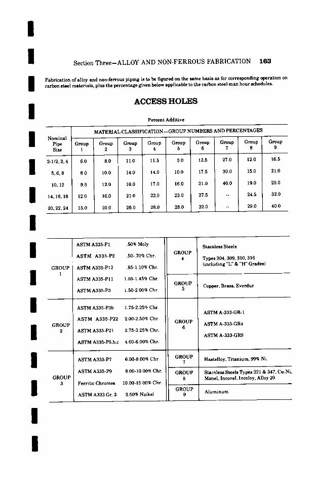
I I I /
Section Three--ALLOY AND NON-FERROUS FABRICATION 183
Fabrication of alloy and non-ferrous piping is to be figured on the same basis as for corresponding operation on carbon steel materials, plus the percentage given below applicable to the carbon steel man hour schedules.
ACCESS HOLES
Percent Additive
I I I I B I I I I I I
Nominal Pipe Size
2-I/2, 3, 4
5,6,8
I0, 12
14, 16, 18
20, 22, 24
MATERIAL CLASSIFICATION--GROUP NUMBERS AND PERCENTAGES
Group Group Group Group Group Group Group Group Group 1 2 3 4 5 6 7 8 9
6.0 8.0 II.0 11.5 5.0 13.5 27.0 12.0 16.5
8.0 10.0 14.0 14.0 10.0 17.5 30.0 15.0 21.0
9.5 12.0 16.0 17.0 16.0 21.0 40.0 19.0 25.0
12.0 16.0 21.0 22.0 23.0 27.5
15.0 20.0 26.0 28.0 28.0 32.0
24.5 32.0
29.0 40.0
GROUP 1
GROUP 2
GROUP 3
ASTM A335-PI .50~ Moly
ASTM A335-P2 .50-.70% Chr.
ASTM A335-PI2 .85-I.I0q~ Chr.
AST.M A335-PI 1 1.05-1.45~ Chr.
ASTM A335-P3 1.50-2.00q~ Chr.
ASTM A335-P3b 1.75-2.25% Chr.
ASTM A335-P22 2.00-2.50~ Chr.
ASTM A335-P21 2.75-3.25% Chr.
ASTM A335-P5,b,c 4.00-6.00~ Chr.
ASTM A335-P7 6.00-8.00% Chr.
ASTM A335-P9 8.00-I0.00~ Chr.
Ferritic Chromes I0.00-15.00% Chr.
ASTM A333 Gr. 3 3.50% Nickel
GROUP 4
GROUP 5
GROUP 6
GROUP 7
GROUP 8
GROUP 9
Stainless Steels
Types 304,309, 310,316 (including "L" & "H" Grades)
Copper, Brass, Everdur
ASTM A-333-GR- I
ASTM A-333-GR4
ASTM A-333-GR9
Hastelloy, Titanium, 99~ Ni.
Stainless Steels Types 321 & 347, Cu-Ni, Monel, Inconel, Incoloy, Alloy 20
Aluminum
/
S e c t i o n F o u r
P N E U M A T I C M E C H A N I C A L I N S T R U M E N T A T I O N
l l / / / /
This section is included to cover the complete man hours required for installing pneumat ic mechanical m instrumentat ion, as may be required for the monitor- ing of various process systems.
The man hours listed are for labor only and do not have any bearing on material or equipment cost.
All labor m a n hours are inc luded for unloading, f rom ra i l road cars or t rucks , haul ing to and unload- ing at job s to rage facilities, haul ing f rom s to rage to e rec t ion site, ca l ibra t ing w h e n necessary , posi t ion- ing in place, test ing, and final check.
l / / / /
l
164
/
l l /
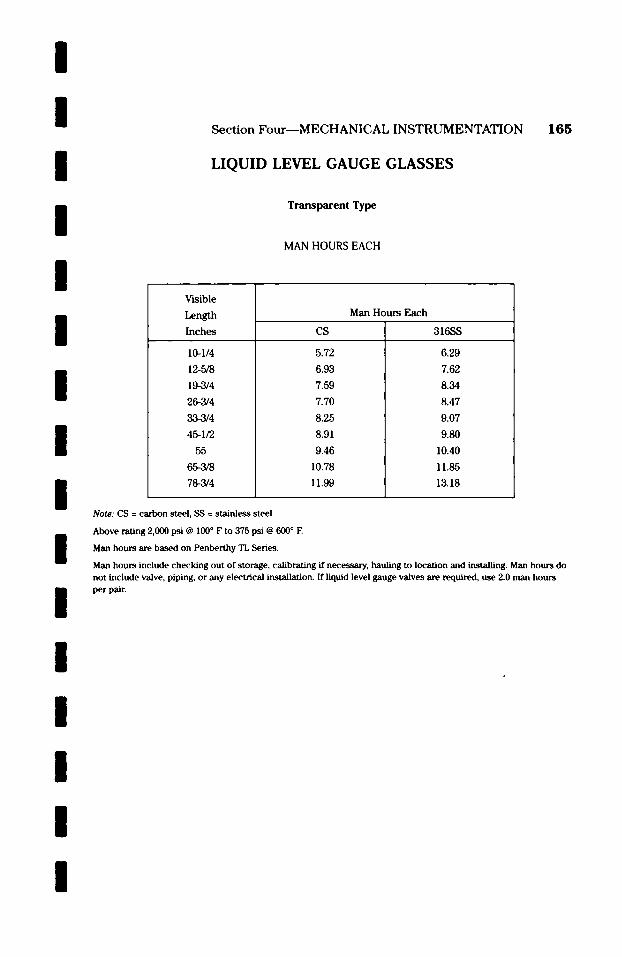
/ /
I I I / / / / /
I / /
I /
Section Four--MECHANICAL INSTRUMENTATION
LIQUID LEVEL GAUGE GLASSES
T r a n s p a r e n t Type
MAN HOURS EACH
165
V'mible
Length Inches
10-1/4
12-5/8
19-3/4
26-3/4
33-3/4
45-1/2
55
65-3/8
78-3/4
Man Hours Each
CS
5.72
6.93
7.59
7.70
8.25
8.91
9.46
10.78
11.99
316SS
6.29
7.62
8.34
8.47
9.07
9.80
10.40
11.85
13.18
Note: CS = carbon steel, SS = stainless steel
Above rating 2,000 psi @ 100 ~ F to 375 psi @ 600 ~ E
Man hours are based on Penberthy TL Series.
Man hours include checking out of storage, calibrating if necessary, hauling to location and installing. Man hours do not include valve, piping, or any electrical installation. If liquid level gauge valves are required, use 2.0 matt hours per pair.
I
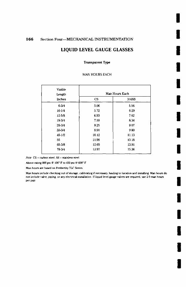
1 6 6 Section Four- -MECHANICAL INSTRUMENTATION
LIQUID LEVEL GAUGE GLASSES
T r a n s p a r e n t Type
MAN HOURS EACH
Visible
Length
Inches
6-3/4
10-1/4
12-5/8
19-,3/4
26-3/4
33-3/4
45-1/2
55
65-3/8
78-3/4
CS
5.06
5.72
6.93
7.59
8.25
8.91
10.12
11.99
12.65
13.97
Man Hours Each
316SS
5.56
6.29
7.62
8.34
9.07
9.80
11.13
13.18
13.91
15.36
Note: CS = carbon steel, SS = stainless steel
Above rating 800 psi @ 100 ~ F to 450 psi @ 600 ~ F
Man hours are based on Penberthy TLC Series.
Man hours include checking out of storage, calibrating if necessary, hauling to location and installing. Man hours do not include valve, piping, or any electrical installation. If liquid level gauge valves are required, use 2.0 man hours per pair.
I I I l l l l I l l l l I l l l
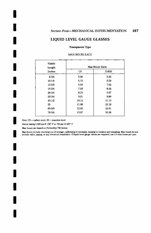
l / /
l /
l / /
l /
l I / / /
Section Four--MECHANICAL INSTRUMENTATION 167
LIQUID LEVEL GAUGE GLASSES
Transparent Type
MAN HOURS EACH
Visible
Length I n c h e s
6-3/4
10-1/4
12-5/8
19-3/4
26-3/4
33-3/4
45-1/2
55
65-3/8
78-3/4
CS
5.06
5.72
6.93
7.59
8.25
8.91
10.12
11.99
12.65
13.97
Man H o u r s E a c h
316SS
5.56
6.29
7.62
8.34
9.07
9.80
11.13
13.18
13.91
15.36
Note: CS = carbon steel, SS = stainless steel
Above rating 2,500 psi @ 100 ~ F to 750 psi @ 600 ~ F.
Man hours are based on Penberthy TM Series.
Man hours include checking out of storage, calibrat2ng ff necessary, hauling to location and installing. Man hours do not include valve, piping, or any electrical installation. If liquid level gauge valves are required, use 2.0 man hours per pair.
/

1 6 8 Section Four--MECHANICAL INSTRUMENTATION
LIQUID LEVEL GAUGE GLASSES
T r a n s p a r e n t Type
MAN HOURS EACH
Visible
Length Inches
6-3/4
10-1/4
12-5/8
19-3/4
26-3/4
33-1/4
45-1/2
55
65-3/8
78-3/4
CS
4.40
5.06
6.38
6.93
6.98
7.59
8.25
8.91
10.12
11.44
Man Hours Each
316SS
4.84
5.56
7.01
7.62
7.67
8.34
9.07
9.80
11.13
12.58
Note: CS = carbon steel, SS = stainless steel
Above rating 3,000 psi @ 100 ~ F to 1,500 psi @ 600 ~ E
Man hours are based on Penberthy TH Series.
Man hours include checking out of storage, calibrating if necessary, hauling to location and installing. Man hours do not include valve, piping, or any electrical installation. If liquid level gauge valves are required, use 2.0 man hours per pair.
/ / / /
l / / / / / / /
l l /
l
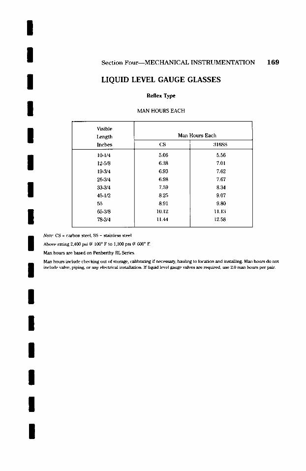
/
l / / / /
l /
l /
l / / / /
Section F o u r - - M E C H A N I C A L INSTRUMENTATION 169
LIQUID LEVEL GAUGE GLASSES
Reflex Type
MAN HOURS EACH
Visible
Leng th
I n c h e s
10-1/4
12-5/8
19-3/4
26-3/4
33-3/4
45-1/2
55
65-3/8
78-3/4
CS
5.06
6.38
6.93
6.98
7.59
8.25
8.91
10.12
11.44
Man Hour s E a c h
316SS
5.56
7.01
7.62
7.67
8.34
9.07
9.80
11.13
12.58
Note: CS = carbon steel, SS = stainless steel
Above rating 2,400 psi @ 100 ~ F to 1,300 psi @ 600 ~ E
Man hours are based on Penberthy RL Series.
Man hours include checking out of morage, calibrating if necessary, hauling to location and installing. Man hours do not include valve, piping, or any elec~xical installation. If liquid level gauge valves are required, use 2.0 man hours per pair.
/
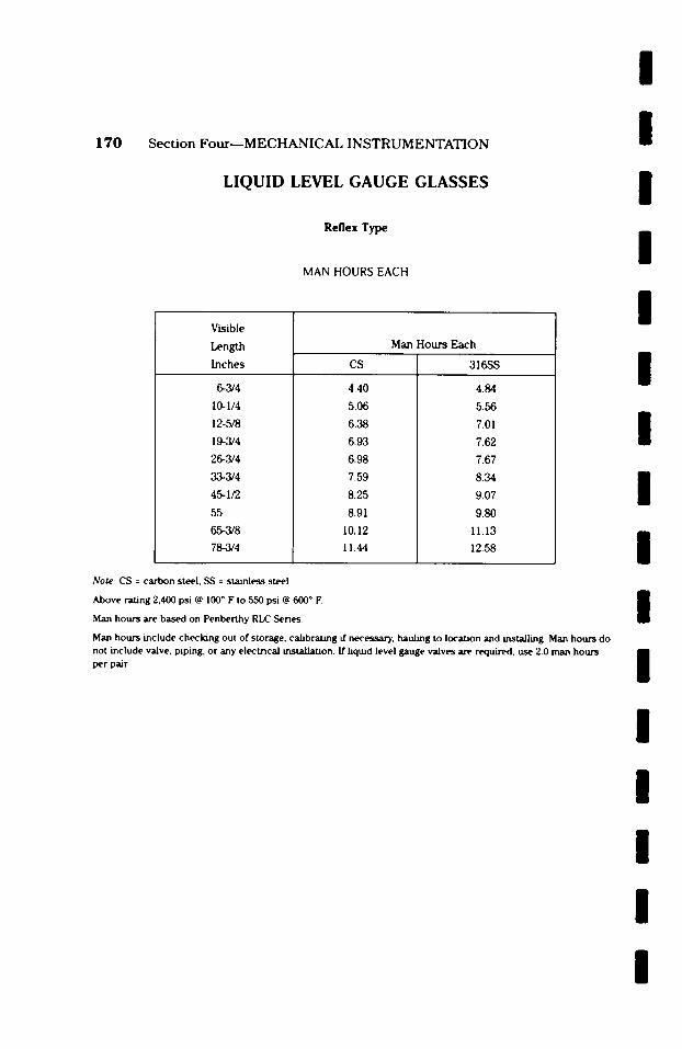
170 Section Four--MECHANICAL INSTRUMENTATION
LIQUID LEVEL GAUGE GLASSES
Reflex Type
MAN HOURS EACH
Visible
Length Inches
6-3/4
10-1/4
12-5/8
19-3/4
26-3/4
33-3/4
45-1/2
55
65-3/8
78-,3/4
CS
4.40
5.06
6.38
6.93
6.98
7.59
8.25
8.91
10.12
11.44
Man Hour s Each
316SS
4.84
5.56
7.01
7.62
7.67
8.34
9.07
9.80
11.13
12.58
Note: CS = carbon steel, SS = stainless steel
Above rating 2,400 psi @ 100 ~ F to 550 psi ~ 600 ~ F'.
Man hours are based on Penberthy RLC Senes.
Man hours include checking out of storage, calibrating if necessary, hauling to location and installing. Man hours do not include valve, piping, or any electrical installation. [f liquid level gauge valves are requirt~, use 2.0 man hours per pair.
I I I I I I I I I I I I I I I I
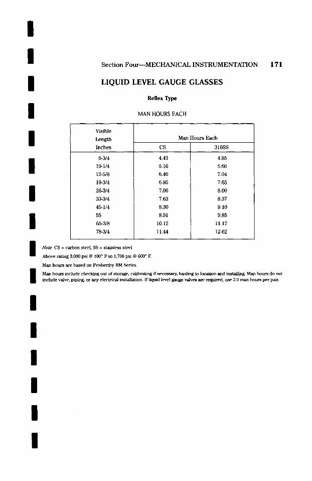
/ / / / /
l / / / / / / /
l /
Section Four--MECHANICAL INSTRUMENTATION 171
LIQUID LEVEL GAUGE GLASSES
Reflex Type
MAN HOURS EACH
Visible
Length I n c h e s
6-3/4
10-1/4
12-5/8
19-3/4
26-3/4
33-3/4
45-1/4
55
65-3/8
78-3/4
CS
4.43
5.10
6.40
6.95
7.00
7.63
8.30
8.91
10.12
11.44
Man Hour s E a c h
316SS
4.85
5.60
7.04
7.65
8.00
8.37
9.10
9.85
11.17
12.62
Note: CS = carbon steel, SS = stainless steel
Above rating 3,000 psi @ 100 ~ F to 1,700 psi @ 600 ~ E
Man hours are based on Penberthy RM Series.
Man hours include checking out of storage, calibrating if necessary, hauling to location and installing. Man hours do not include valve, piping, or any electrical installation. If liquid level gauge .valves are required, use 2.0 man hours per pair.
l
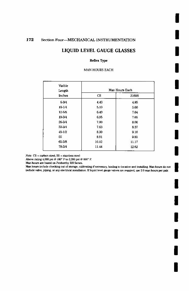
1 7 2 Section Four--MECHANICAL INSTRUMENTATION
LIQUID LEVEL GAUGE GLASSES
Reflex Type
MAN HOURS EACH
~rlsible
Length Inches
6-3/4
10-1/4
12-5/8
19-3/4
26-3/4
33-3/4
45-1/2
55
65-3/8
78-3/4
CS
4.43
5.10
6.40
6.95
7.00
7.63
8.30
8.91
10.12
11.44
Man Hours Each
316SS
4.85
5.60
7.04
7.65
8.00
8.37
9.10
9.85
11.17
12.62
/ / / / / / / / /
Note: CS = carbon steel, SS = stainless steel Above rating 4,000 psi @ 100 ~ F to 2,200 psi @ 600 ~ E Man hours are based on Penberthy RH Series. mm Man hours include checking out of storage, calibrating if necessary, hauling to location and ~ Man hours do not 1 include valve, piping, or any electrical installation. If liquid level gauge valves are required, use 2.0 man hours per pair.
/ / / / / /
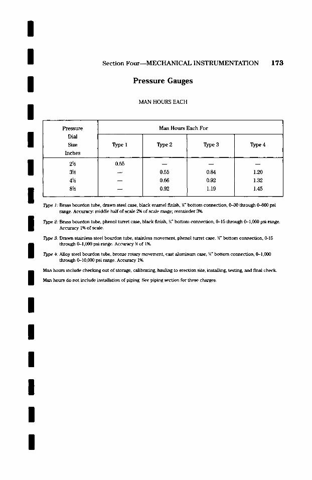
/ / / /
Section Four--MECHANICAL INSTRUMENTATION
P r e s s u r e Gauges
MAN HOURS EACH
173
/
l l
Pressure
Dial
Size
Inches
2~4
3~
4~4
8~
Man Hours Each For
Type I
0.55
T y p e 2
0.55
0.66
0.92
Type 3
0.84
0.92
1.19
T y p e 4
1.20
1.32
1.45
l / /
l l / / /
Type I: Brass bourdon tube, drawn steel case, black enamel finish, �88 bottom connection, 0-30 through 0-600 psi range. Accuracy: middle haft of scale 2% of scale range; remainder 3%
Type 2: Brass bourdon tube, phenol turret case, black finish, �88 bottom connection, 0-15 through 0-1,000 psi range. Accuracy 1% of scale.
Type 3: Drawn stainless steel bourdon tube, stainless movement, phenol turret case, �88 bottom connection, 0-15 through 0--I,000 psi range. Accuracy �89 of I~
Type 4: Alloy steel bourdon tube, bronze rotary movement, cast aluminum case, �88 bottom connection, 0-1,000 through 0-I0,000 psi range. Accuracy I%
Man hours include checking out of storage, calibrating, hauling to erection site, installing, testing, and f'mal check.
Man hours do not include installation of piping. See piping section for these charges.
l
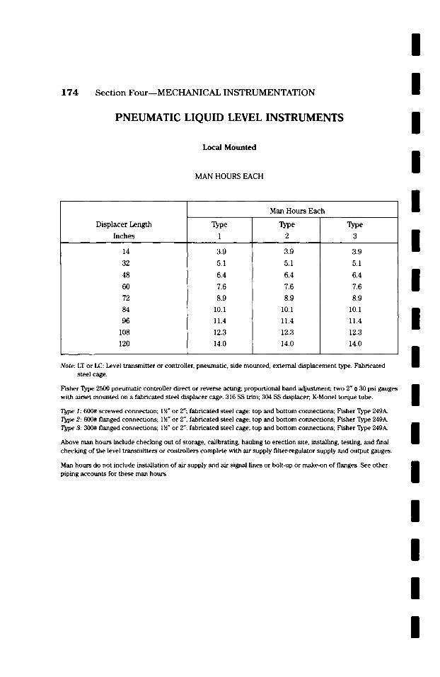
174 Section FourmMECHANICAL INSTRUMENTATION
PNEUMATIC LIQUID LEVEL INSTRUMENTS
Loca l M o u n t e d
MAN HOURS EACH
Man Hours Each
/ / / / /
Displacer Length
Inches
14
32
48
60
72
84
96
108
120
Type
1
3.9
5.1
6.4
7.6
8.9
10.1
11.4
12.3
14.0
Type
2
3.9
5.1
6.4
7.6
8.9
10.1
11.4
12.3
14.0
3
3.9
5.1
6.4
7.6
8.9
10.1
11.4
12.3
14.0
Note: LT or LC: Level transmitter or controller, pneumatic, side mounted, external displacement type. Fabricated
l l l l
steel cage.
Fisher Type 2500 pneumatic controller direct or reverse acting; proportional band adjustment; two 2" ~ 30 psi gauges with airset mounted on a fabricated steel displacer cage. 316 SS trim; 304 SS displacer, K-Monel torque tube.
Type I: 6(}0# screwed connection; ! �89 or 2"; fabricated steel cage; top and bottom connections; Fisher Type 249A. 2: 600# flanged connections; 1�89 or 2"; fabricated steel cage; top and bottom connections; Fisher Type 249A.
Type 3: 300# flanged connections; 1�89 or 2"; fabricated steel cage; top and bottom connections; Fisher Type 249A.
Above man hours include checking out of storage, calibrating, hauling to erection site, installing, testing, and final checking of the level transmitters or controllers complete with air supply filter-regulator supply and output gauges.
Man hours do not include installation of air supply and air signal lines or bolt-up or make-on of flanges. See other piping accounts for these man hours.
/ /
l / / /
l
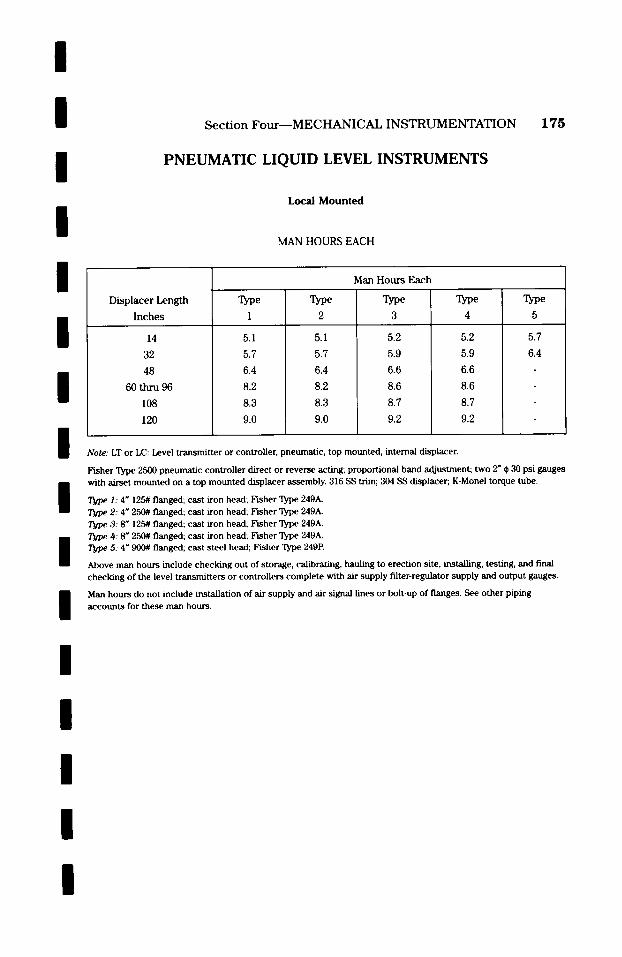
/
/ / /
/
/ /
/
Section Four--MECHANICAL INSTRUMENTATION
PNEUMATIC LIQUID LEVEL INSTRUMENTS
Local Mounted
MAN HOURS EACH
Displacer Length
Inches
14
32
48
60 thru 96
108
120
Type
1
5.1
5.7
6.4
8.2
8.3
9.0
Type
2
5.1
5.7
6.4
8.2
8.3
9.0
Man Hours Each
Type
3
5.2
5.9
6.6
8.6
8.7
9.2
Type 4
5.2
5.9
6.6
8.6
8.7
9.2
Note: LT or LC: Level transmitter or controller, pneumatic, top mounted, internal displacer.
175
Type
5
5.7
6.4
/
Fisher Type 2500 pneumatic controller direct or reverse acting; proportional band adjustment; two 2" 0 30 psi gauges with airset mounted on a top mounted displacer assembly. 316 SS trim; 304 SS displacer, K-Monel torque tube.
I Type I: 4" 125# flanged; cast iron head; Fisher Type 249A~ Type 2: 4" 250# flanged; cast iron head; Pisher Type 249~ Type 3: 8" 125# flanged; cast iron head; Fisher Type 249A. Type 4: 8" 2,50# flanged; cast iron head; Fisher Type 249A.
l Type 5: 4" 900# flanged; cast steel head; Fisher Type 249P.
Above man hours include checking out of storage, calibrating, hauling to erection site, installing, testing, and final checking of the level transmitters or controllers complete with air supply filter-regulator supply and output gauges.
Man hours do not include installation of air supply and air signal lines or bolt-up of flanges. See other piping accounts for these man hours.
/ /
l /
/
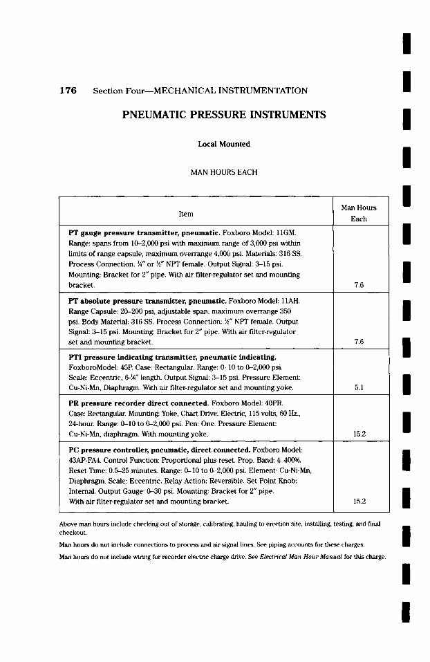
/
176 S e c t i o n F o u r m M E C H A N I C A L I N S T R U M E N T A T I O N
PNEUMATIC PRESSURE INSTRUMENTS
Local Mounted
MAN HOURS EACH
Man Hours
/
/
/
/ Item
PT gauge pressure transmitter, pneumatic. Foxboro Model: I lGM.
Range: spans from 10-2,000 psi with maximum range of 3,000 psi within
limits of range capsule, maximum overrange 4,000 psi. Materials: 316 SS.
Process Connection: �88 or ~" NPT female. Output Signal: 3-15 psi.
Mounting: Bracket for 2" pipe. with air filter-regulator set and mounting
bracket.
PT absolute pressure t ransmit ter , pneumatic. Foxboro Model: 11AH.
Range Capsule: 20-200 psi, adjustable span, maximum overrange 350 psi. Body Material: 316 SS. Process Connection: ~" NPT female. Output Signal: 3-15 psi. Mounting: Bracket for 2" pipe. With air filter-regulator set and mounting bracket.
PTI p ressure indicat ing t ransmi t te r , pneumat ic indicating. FoxboroModel: 45P. Case: Rectangular. Range: 0-10 to 0-2,000 psi. Scale: Eccentric, 6-~" length. Output Signal: 3-15 psi. Pressure Element: Cu-Ni-Mn, Diaphragm. With air filter-regulator set and mounting yoke.
PR pressure recorder d i rect connected. Foxboro Model: 40PR. Case: Rectangular. Mounting: Yoke, Chart Drive: Electric, 115 volts, 60 Hz., 24-hour. Range: 0-10 to 0-2,000 psi. Pen: One. Pressure Element:
Cu-Ni-Mn, diaphragm. With mounting yoke.
PC pressure controller, pneumatic, direct connected. Foxboro Model: 43AP-FA4. Control Function: Proportional plus reset. Prop. Band: 4--4(X)%.
Reset Time: 0.5-25 minutes. Range: 0-10 to 0-2,000 psi. Element: Cu-Ni-Mn, Diaphragm. Scale: Eccentric. Relay Action: Reversible. Set Point Knob:
Internal. Output Gauge: 0-30 psi. Mounting: Bracket for 2" pipe. With air filter-regulator set and mounting bracket.
Each
7.6
7.6
5.1
15.2
15.2
/
/
/ / / /
/
/ Above man hours include checking out of storage, calibrating, hauling to erection site, installing, testing, and final checkout.
Man hours do not include connections to process and air signal lines. See piping accounts for these charges.
Man hours do not include wiring for recorder electric charge drive. See Electrical Man Hour Manual for this charge.
/
/
/
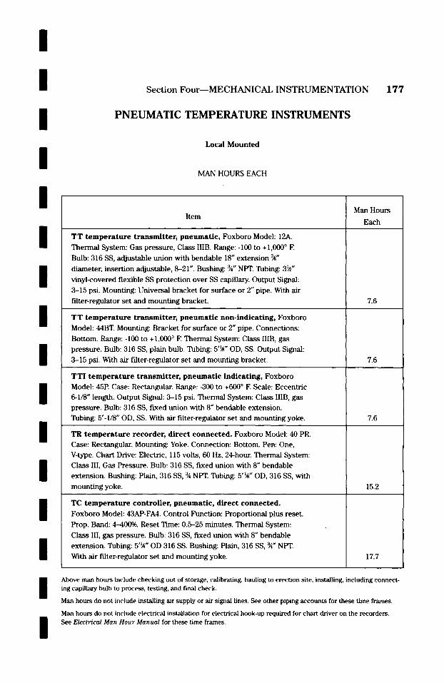
I /
/ /
/
Section Four--MECHANICAL INSTRUMENTATION 177
P N E U M A T I C TEMPERATURE I N S T R U M E N T S
Local Mounted
MAN HOURS EACH
Man Hours
/
/
/ / / /
I /
/
Item
T T t e m p e r a t u r e transmitter, pneumatic, Foxboro Model: 12A.
Thermal System: Gas pressure, Class IIIB. Range: -I00 to + 1,000 ~ F.
Bulb: 316 SS, adjustable union with bendable 18" extension '~"
diameter, insertion adjustable, 8--21". Bushing: ~" NPT. Tubing: 3~"
vinyl-covered flexible SS protection over SS capillary. Output Signal:
3--15 psi. Mounting: Universal bracket for surface or 2" pipe. With air
filter-regulator set and mounting bracket.
T T t e m p e r a t u r e t r ansmi t t e r , pneumatic non-indicating, Foxboro Model: 44BT. Mounting: Bracket for surface or 2" pipe. Connections:
Bottom. Range: -I00 to + 1,000 ~ F. Thermal System: Class IIIB, gas
pressure. Bulb: 316 SS, plain bulb. Tubing: 5%" OD, SS. Output Signal: 3-15 psi. With air filter-regulator set and mounting bracket.
TTI temperature transmitter, pneumatic indicating, Foxboro
Model: 45P. Case: Rectangular. Range: -300 to +600 ~ F. Scale: Eccentric 6-1/8" length. Output Signal: 3-15 psi. Thermal System: Class IIIB, gas
pressure. Bulb: 316 SS, fLxed union with 8" bendable extension.
Tubing: 5'-1/8" OD, SS. With air filter-regulator set and mounting yoke.
Tit temperature recorder, direct connected. Foxboro Model: 40 PR. Case: Rectangular. Mounting: Yoke. Connection: Bottom. Pen: One,
V-type. Chart Drive: Electric, 115 volts, 60 Hz, 24-hour. Thermal System:
Class llI, Gas Pressure. Bulb: 316 SS, fLxed union with 8" bendable
extension. Bushing: Plain, 316 SS, ~ NPT. Tubing: 5' ~" OD, 316 SS, with
mounting yoke.
TC temperature controller, pneumatic, direct connected. Foxboro Model: 43AP-FA4. Control Function: Proportional plus reseL
Prop. Band: 4-400%. Reset Time: 0.5--25 minutes. Thermal System:
Class III, gas pressure. Bulb: 316 SS, fixed union with 8" bendable
extension. Tubing: 5'Ni" OD 316 SS. Bushing: Plain, 316 SS, :�88 NPT.
With air filter-regulator set and mounting yoke.
Each
7.6
7.6
7.6
15.2
17.7
/
I
Above man hours include checking out of storage, calibrating, hauling to erection site, installing, including connect- ing capillary bulb to process, testing, and final check.
Man hours do not include installing air supply or air signal lines. See other piping accounts for these time frames.
Man hours do not include electrical installation for electrical hook-up required for chart driver on the recorders. See Electrical Man Hour Manual for these time frames.

/
1 7 8 S e c t i o n F o u r m M E C H A N I C A L I N S T R U M E N T A T I O N
THERMOMETERS AND THERMOWELLS
MAN HOURS EACH
/
/
/ Thermometer
Description
Straight form 7" scale, 3~" stem
Straight form 9" scale, 6" stem
Straight form 12" scale, 12" stem
Angle form 7" scale, 3~" stem
Angle form 9" scale, 6" stem
Angle form 12" scale, 12" stem
Every angle adjustable, 7" scale, 3~" stem
Every angle adjustable, 9" scale, 6" stem
Every angle adjustable, 12" scale, 12" stem
Man Hour
Each
0.77
0.84
0.92
0.77
0.84
0.92
0.77
0.84
0.92
Man hours are for thermometers, mercury in glass type, epoxy-coated aluminum case, red-reading mercury; -40 ~ F
l
/
/
/ minimum to 750 ~ F maximum range (600 ~ F maximum temperature differential span), stainless steel stem and including separable 316 stainless steel well with �90 NPT (external thread).
Man hours include checking out of storage, hauling to erection site, installing, checking, and testing.
Man hours do not include pipe or pipe fittings. See piping tables for these man hours. N / /
/
N
N /
l

l / /
/
Section Four--MECHANICAL INSTRUMENTATION
T HE RM OM E T E RS AND THERMOWELLS
MAN HOURS EACH
179
/ /
/
/
Thermomete r
Descript ion
Bot tom Connect ion, 3" Dial, 4" Stem
Bot tom Connect ion, 5" Dial, 6" Stem
Bot tom Connect ion, 5" Dial, 12" Stem
Back Connect ion, 3" Dial, 4" Stem
Back Connect ion, 3" Dial, 6" Stem
Back Connect ion, 5" Dial, 12" Stem
Every Angle Adjustable, 5" Dial, 4" Stem
Every Angle Adjustable, 5" Dial, 6" Stem
Every Angle Adjustable, 5" Dial, 12" Stem
Man Hour
Each
0.77
0.84
0.84
0.77
0.77
0.84
0.84
0.84
0.84
/ / / /
Man hours are for thermometers, dial type, bi-metal, 18-8 stainless steel case and stem, scale length approximately two times dial diameter;, - 80 ~ F minimum to 500 ~ F maximum (500 ~ F maximum temperature differential span); and including separable 316 stainless steel well with ~" NPT (external thread).
Man hours include checking out of storage, hauling to erection site, installing, checking, and testing.
Man hours do not include pipe or pipe fittings. See piping tables for these man hours.
T H E R M O M E T E R S AND THERMOWELLS
MAN HOURS EACH
l
l
Thermomete r Descript ion
4~" Dial, 3~" Immers ion on Bulb
6" Dial, 6" Immers ion on Bulb
8" Dial, 12" Immers ion on Bulb
Man Hours
Each
1.10
1.20
1.30
/
l
Above man hours are for thermometers, dial type, remote reading, t'dled system type, mercury actuated, lower or back connected phenolic case for wall or flush mounting, stainless steel movement, complete with 188 stainless steel bulb, flexible extension and 5 lineal feet of copper capillary; -20 ~ F minimum to 1,0000 F maximum range, (800 ~ F maximum temperature differential span). ~" NIP union connection including 316 stainless steel well with ~" NPT (external thread).
Man hours include checking out of storage, hauling to erection site, installing, checking, and testing.
Man hours do not include pipe or pipe fittings. See piping tables for these man hours.
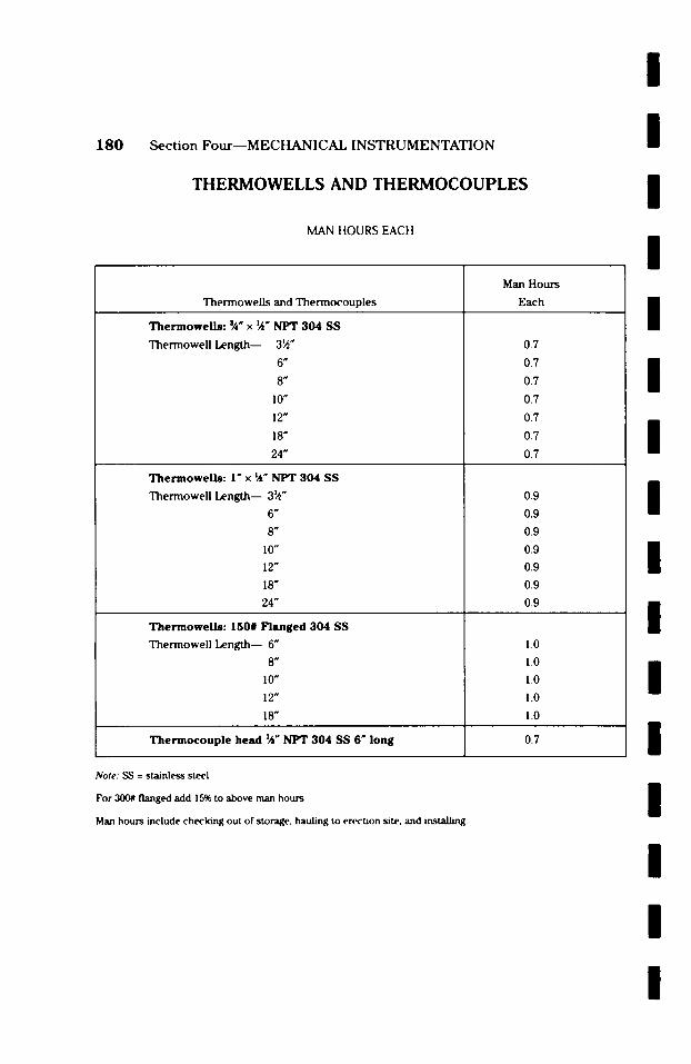
I
180 Section Four- -MECHANICAL INSTRUMENTATION
THERMOWELLS AND THERMOCOUPLES
MAN HOURS EACH
/
/
/ Thermowells and Thermocouples
T h e m o w e l l s : ~ " x ~" NFT 304 SS
Thermowell Length-- 3~"
6"
8"
I0"
12"
18"
24"
T h e r m o w e l l s : I" x ~" NPT 304 SS
Thermowell Length-- 3~"
6"
8"
I0"
12"
18"
24"
T h e m o w e l l s : 150# Flanged 304 SS
Thermowell Length-- 6"
8"
10"
12"
18"
T h e r m o c o u p l e head ~" NFT 304 SS 6" long
Man Hours
Each
0.7
0.7
0.7
0.7
0.7
0.7
0.7
0.9
0.9
0.9
0.9
0.9
0.9
0.9
l.O
1.0
1.0
1.0
1.0
0.7
/
/
/
I / / /
/ Note: SS = stainless steel
For 300# flanged add 15% to above man hours
Man hours include checking out of storage, hauling to erection site, and installing. I I I I

/
/ /
l / /
l / /
Section Four--MECHANICAL INSTRUMENTATION
RELIEF VALVES
181
M A N HOURS EACH
Type Size
Inches
~ x l
:~4xl
l x l
~ x l
h x l
l x l
Man Hour
Each
0.9
1.0
1.0
0.9
1.0
1.0
Type A: Screwed relief valve, carbon steel body, carbon steel spring, pressure limit 2,000#, maximum temperature 600 ~ F.
Type B: Screwed relief valve, carbon steel body, alloy steel spring, pressure limit 2,0(X)#, maximum temperature 750 ~ F.
Man hours include checking out of storage, hauling to erection site, installing, testing, and checking.
Man hours do not include piping to or from the valve or supports if required. See other piping tables for these requirements.
/ / /
l
l /
/

/
182 S e c t i o n F o u r m M E C H A N I C A L I N S T R U M E N T A T I O N
FLANGED RELIEF VALVES
MAN HOURS EACH
/
/
/ Inlet and Out le t
Size
Inches
Ix2
l~x2
l~x2~
150#
l~x3
2x3
2~x4
3x4
4x6
6x8
6x10
8x10
1.4
1.5
1.5
1.5
1.6
2.0
2.7
3.6
Man Hours Each
Flange Rating
4.8
3OO#
1.6
1.6
1.7
1.7
2.3
2.3
3.1
4.1
4.7
5.4
6OO#
1.8
1.8
1.9
1.9
2.5
2.5
3.3
4.4
5.0
5.8
/
/
/
/ Above are standard relief valves A-216 grade WCB carbon steel body, closed bonnet with screwed cap, carbon steel spring. Maximum temperature 4,50 ~ F.
Man hours include checking out of storage, hauling to erection site, installing, testing, and checking ouL
Man hours do not include piping to or from the valve or supports if required. See other piping tables for these requirements.
/ / /
/
/
/
/
/
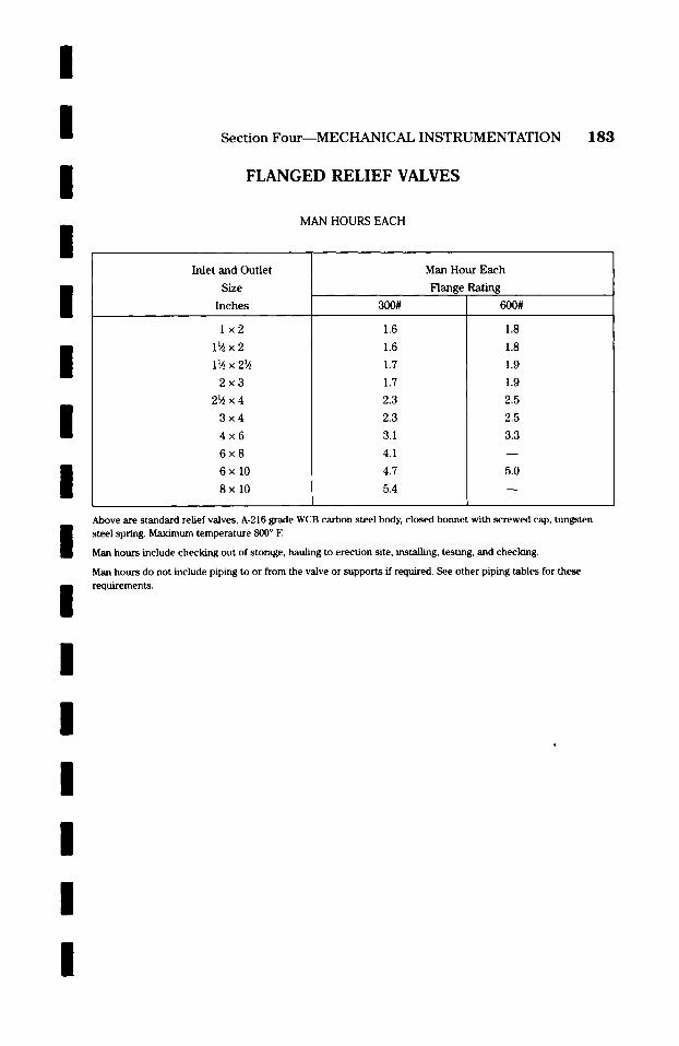
/ / / /
Section Four--MECHANICAL INSTRUMENTATION
F L A N G E D RELIEF VALVES
MAN HOURS EACH
183
/ / /
I
Inlet and Outlet
Size
Inches
Ix2
l~x2
l~x2~
300#
1.6
1.6
1.7
Man Hour Each
Flange Rating
6O0#
1.8
1.8
1.9
2x3
29~x4
3x4
4x6
6x8
6xlO
8xlO
1.7
2.3
2.3
3.1
4.1
4.7
5.4
1.9
2.5
2.5
3.3
5.0
/ / /
Above are standard relief valves, A-216 grade WCB carbon steel body, closed bonnet with screwed cap, tungsten steel spring. Maximum temperature 800 ~ E
Man hours include checking out of storage, hauling to erection site, installing, testing, and checking.
Man hours do not include piping to or from the valve or supports if required. See other piping tables for these requirements.
/
/ / /
/
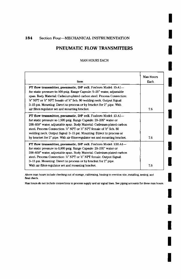
/
184 S e c t i o n F o u r m M E C H A N I C A L I N S T R U M E N T A T I O N
PNEUMATIC FLOW TRANSMITTERS
MAN HOURS EACH
/ /
/ Item
FT flow t ransmi t t e r , pneumat ic , D/P cell. Foxboro Model: 15-A1
for static pressure to 500 psig. Range Capsule: 5-25" water, adjustable
span. Body Material: Cadmium-plated carbon steel. Process Connection:
�88 NPT or 9i" NPT female of 9i" Sch. 80 welding neck. Output Signal:
3-15 psi. Mounting: Direct to process or by bracket for 2" pipe. With
air filter-regulator set and mounting bracket.
FT flow t ransmi t t e r , pneumat ic , D/P cell. Foxboro Model: 13-A1--
for static pressure to 1,500 psig. Range Capsule: 20-205" water or
2 ~ water, adjustable span. Body Material: Cadmium-plated carbon
steel. Process Connection: �88 NPT or 9i" NPT female of 9!" Sch. 80 welding neck. Output Signal: 3-15 psi. Mounting: Direct to process or
by bracket for 2" pipe. With air filter-regulator set and mounting bracket.
FT flow t ransmi t t e r , pneumat ic , D/P cell. Foxboro Model: 13H-AI for static pressure to 6,000 psig. Range Capsule: 20-205" water or 20(0-850" water, adjustable span. Body Material: Cadmium-plated carbon steel. Process Connection: �88 NPT or 91" NPT female. Output Signal:
3-15 psi. Mounting: Direct to process or by bracket for 2" pipe. With air filter-regulator set and mounting bracket.
Man Hours
Each
7.6
7.6
7.6
/
/
/
l l /
Above man hours include checking out of storage, calibrating, hauling to erection site, installing, testing, and f'mal check.
Man hours do not include connections to process supply and air signal lines. See piping accounts for these man hours. l l l l l l
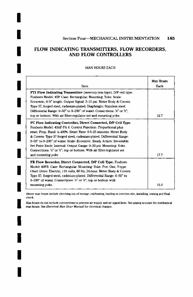
/ / / /
Section Four--MECHANICAL INSTRUMENTATION
FLOW INDICATING TRANSMITTERS, FLOW RECORDERS, AND FLOW CONTROLLERS
MAN HOURS EACH
185
l / / / / / /
Item
FTI Flow Indica t ing T ransmi t t e r (mercury-less type), D/P cell type.
Foxboro Model: 45P. Case: Rectangular. Mounting: Yoke. Scale:
Eccentric, 6-~i" length. Output Signal: 3-15 psi. Meter Body & Covers:
Type 37, forged steel, cadmium-plated. Diaphragm: Stainless steel.
Differential Range: 0-50" to 0-200" of water. Connections: �88 or ~";
top or bottom. With air filter-regulator set and mounting yoke.
FC Flow Indicating Controller, Direct Connected, D/P Cell Type.
Foxboro Model: 43AP-FA 4. Control Function: Proportional plus
reset. Prop. Band: 4-40(0. Reset Tune: 0.5-25 minutes. Meter Body
& Covers: Type 37 forged steel, cadmium-plated. Differential Range:
0-50" to 0-200" of water. Scale: Eccentric. Ready Action: Reversible.
Set Point Knob: Internal. Output Gauge: 0-30 psi. Mounting: Yoke.
Connections: �88 or ~4"; top or bottom. With air filter-regulator set
and mounting yoke.
FR Flow Recorder, Direct Connected, D/P Cell Type. Foxboro
Model: 40PR. Case: Rectangular. Mounting: Yoke. Pen: One, V-type. Chart Drive" Electric, 115 volts, 60 Hz, 24-hour. Meter Body & Covers:
Type 37, forged steel, cadmium-plated. Differential Range: 0-50" to
0-200" of water. Connections: �88 or ~"; top or bottom with
mounting yoke.
Man Hours
Each
12.7
17.7
15.2
/ Above man hours include checking out of storage, calibrating, hauling to erection site, installing, testing and final check.
Man hours do not include connections to process air supply and air signal lines. See piping account for mechanical man hours. See Electrical Man Hour Manual for electrical charges.
/
l /
/
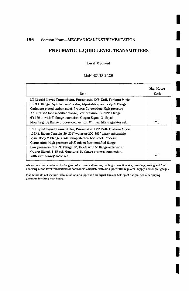
l
1 8 6 Section Four--MECHANICAL INSTRUMENTATION
PNEUMATIC LIQUID LEVEL TRANSMITTERS
Local Mounted
MAN HOURS EACH
Item
LT Liquid Level Transmi t te r , Pneumat i c , D/P Cell. Foxboro Model:
15FAI. Range Capsule: 5-25 # water, adjustable span. Body & Flange:
Cadmium-plated carbon steel. Process Connection: High pressure-
ANSI raised face modified flange; Low pressure- ~ NPT. Flange:
6"; 150-1b with 5 ~ flange extension. Output Signal: 3-15 psi.
Mounting: By flange process connection. With air filter-regulator set.
LT Liquid Level Transmitter, Pneumatic, D/P Cell. Foxboro Model:
13FA1. Range Capsule: 20--205" water or 2(D-850" water, adjustable
span. Body & Flange: Cadmium-plated carbon steel. Process
Connection: High pressure-ANSI raised face modified flange;
Low pressure- ~ NPT. Flange: 3"; 150-1b with 5" flange extension. Output Signal: 3-15 psi. Mounting: By flange process connection.
With air filter-regulator set.
Man Hours
Each
7.6
7.6
/
/
/
/
/
/
/
l Above man hours include checking out of storage, calibrating, hauling to erection site, installing, testing and final checking of the level transmitters or controllers complete with air supply filter-regulator, supply, and output gauges.
Man hours do not include installation of air supply and air signal lines or bolt-up of flanges. See other piping accounts for these man hours.
/ /
/
/
l /
l
I /
Section Four--MECHANICAL INSTRUMENTATION 187
I
I
I
I
I
Control Panel Installation
Control pane ls are usual ly fabr ica ted by a sub -con t r ac to r who special izes in this type of work. The ins t rumen t s that are to be instal led on the panel boa rd or cabine t are usual ly furn ished to the sub -con t r ac to r by the general contrac tor . Panel b o a r d s are usually fabr icated in sec t ions up to approxi- mate ly 12'0" in length.
To un load cont ro l panel f rom carrier, move into posi t ion, and set on foun- dation. Per l inear foot of contro l boa rd length . . . . . . . . . . . . 1.5 man hours
If more than one sec t ion of cont ro l panel is required, add an addi t ional t ime for each connec t ion . . . . . . . . . . . . . . 2.5 man hours
I I / / /
I /
I
I
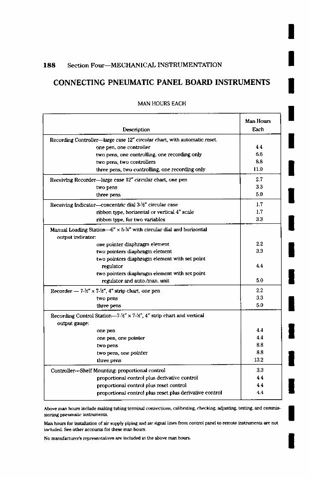
188 Section Four--MECHANICAL INSTRUMENTATION
CONNECTING PNEUMATIC PANEL BOARD INSTRUMENTS
MAN HOURS EACH
Man Hours
l l /
/ Description
Recording Controller--large case 12" circular chart, with automatic reset
one pen, one controller
two pens, one controlling, one recording only
two pens, two controllers
three pens, two controlling, one recording only
Receiving Recorder--large case 12" circular chart, one pen
two pens
three pens
Receiving Indicator---concentric dial 3-~i" circular case
ribbon type, horizontal or vertical 4" scale
ribbon type, for two variables
Manual Loading Station---6" x 5-�88 with circular dial and horizontal
output indicator.
one pointer diaphragm element
two pointers diaphragm element
two pointers diaphragm element with set point
regulator
two pointers diaphragm element with set point
regulator and autoJman, unit
Recorder 7-~" x 7-~", 4" strip chart, one pen
two pens
three pens
Recording Control Station--7-~" x 7-~", 4" strip chart and vertical
output gauge:
one pen
one pen, one pointer
two pens
two pens, one pointer
three pens
Controller--Shelf Mounting: proportional control
proportional control plus derivative control
proportional control plus reset control
proportional control plus reset plus derivative control
Each
4.4
6.6
8.8
11.0
2.7
3.3
5.0
1.7
1.7
3.3
2.2 3.3
4.4
5.0
2.2
3.3
5.0
4.4
4.4
8.8
8.8
13.2
3.3
4.4
4.4
4.4
l l l l l l l l l l
Above man hours include making tubing terminal connections, calibrating, checking, adjusting, testing, and commis- sioning pneumatic instruments.
Man hours for installation of air supply piping and air signal lines from control panel to remote instruments are not included. See other accounts for these man hours.
No manufacturer's representatives are included in the above man hours.
l l

l l /
l
Section Four--MECHANICAL INSTRUMENTATION 189
CONNECTING PNEUMATIC PANEL BOARD INSTRUMENTS
MAN HOURS EACH
/
l /
l l / / / / /
Description
Controller with Local/Remote Set Point---shelf mounting, proportional
control
proportional control plus derivative control
proportional control plus reset control
proportional control plus reset plus derivative control
Manual Loading Stations--shelf-mounted with output indication
shelf-mounted with input and output indication
Auto./Manual Switching Station--shelf-mounted with input and output
indication
Ratio Station--shelf-mounted with manual ratio setting
add for input indication
Receiver Recorder--shelf-mounted, 2 units wide, roll or scan-fold
chart: one pen
two pens
three pens
four pens
Flow Integrator--6-digit actual flow indicator
Multipoint Temperature Recorder, per pt.
Multipoint Temperature Indicator, per pt.
Miscellaneous Pneumatic Panel Instruments, Rear of Panel Mounting:
Analog computer for multiplying two variables, or dividing one
variable by a second one, or extracting square root of one variable,
or squaring one variable
Man Hours
Each
3.9
5.0
5.0
5.0
2.2
2.2
2.2
3.3
1.1
2.2
3.3
5.0
6.6
2.2
1.1
3.3
Square Root Extractor, Input 3-15 psi 2.2
Reversing Relay, 1:1 Ratio 1.1
Booster Relay, 1:1 Ratio 1.1
Selector Relay, High or Low of 2 Pressures 1.1
Limit Relay, high limit 1.1
Limit Relay, low limit 1.1
/
l
Above man hours include making tubing terminal connections, calibrating, checking, adjusting, testing and commis- sioning pneumatic instruments.
Man hours for installation of air supply piping and air signal lines from control panel to remote instruments is not included. See other accounts for these man hours.
No manufacturer's representatives are included in the above man hours.
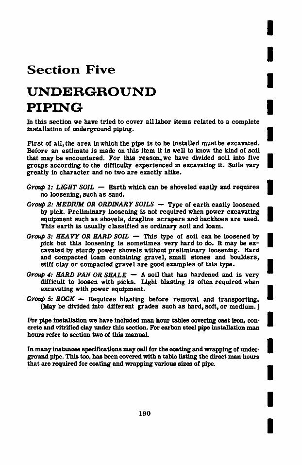
S e c t i o n F i v e
U N D E R G R O U N D P I P I N G In this section we have tr ied to cover all labor items related to a complete installation of underground piping.
F i r s t of all, the area in which the pipe is to be installed must be excavated. Before an estimate is made on this item it is well to know the kind of soft that may be encountered. For this reason, we have divided soil into five groups according to the difficulty experienced in excavating it. Soils vary greatly in character and no two are exactly alike.
/
l / / /
l /
Group 1: LIGHT SOIL - - Earth which can be shoveled easily and requires i no loosening, such as sand. i
Group 2: MEDIUM OR ORDINARY SOILS - - Type of earth easily loosened by pick. Prel iminary loosening is not required when power excavating i equipment such as shovels, dragline sc rapers and backhoes are used. m This earth is usually classified as ordinary soft and loam.
Group 3: H E A V Y OR HARD SOIL - - This type of soil can be loosened by i pick but this loosening is sometimes very hard to do. It may be ex- | cavated by sturdy power shovels without prel iminary loosening. Hard and compacted loam containing gravel, small stones and boulders, stiff clay or compacted gravel are good examples of this type. i
Group 4: HARD PAN OR SHALE - - A soft that has hardened and is very difficult to loosen with picks. Light blasting is often required when excavating with power equipment, i
i Group 5: R O C K - - R e q u i r e s blasting before removal and transporting. (May be divided into dflferent grades such as hard, soft, or medium. )
For pipe installation we have included man hour tables covering cast iron, con- crete and vitrified clay under this section. For carbon steel pipe installation man hours refer to section two of this manua l
In many inBtances specifications may call for the coating and wrapping of under- ground pipe. This too, has been covered with a table listing the direct man hours that are required for coating and wrapping various sizes of pipe.
190
I l / / /
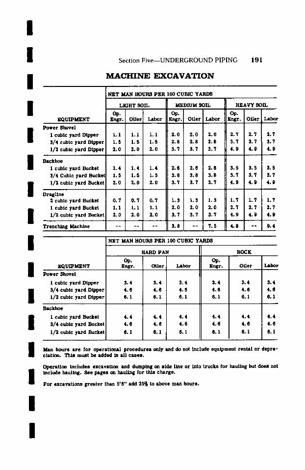
I I /
I
I I /
I /
I / / / /
I
Section Five--UNDERGROUND PIPING 191
M A C H I N E E X C A V A T I O N
NET MAN HOURS PER I00 CUBIC YARDS
~ U I P I ~ N T
Power Shovel ] I cubic yard Dipper 1.1 1.1 1.1 2.0 2.0 ~. 0 3/4 cubic yard Dipper 1.5 1.5 1.5 2.8 2.8 2.8 1/2 cubic yard Dipper 2.0 2.0 2.0 3.7 3.7 3.7
LIGHT SOIL MEDIUM SOIL HEAVY SOIL
Engr. Offer Labor _Engr. Offer Labor gngr. Offer Labo~
2.7 2.7 2.7 3.7 3.7 3.7 4.9 4.9 4.9
Backhoe 1 cubic yard Bucket 1.4 1.4 1.4 2.6 2.6 2.6 3.5 3. 5 3. 5 3/4 Cubic yard Bucket 1.5 I. 5 1.5 3.8 3.8 3.8 3.7 3.7 3.7 1/2 cubic yard Bucket 2.0 2.0 2.0 3.7 3.7 3.7 4.9 4. 9 4.9
Dragllne 2 cubic yard Bucket 0. 7 0. 7 0. 7 I. $ 1.3 1.3 1.7 1.7 1 cubic yard Bucket 1.1 1.1 1.1 2.0 2.0 2.0 2.7 2. 7 1/2 cubic yard Bucket 2.0 2.0 2.0 3. 7 3.7 3. 7 4.9 4. 9
=.
Trenching Machine - - 3.8 - - 7.5 4.8 - -
1.7 2.7 4.9
9.4
NET MAN HOURS PER I00 CUBIC YARDS
KQUIPMENT
Power Shovel
I cubic yard Dipper 3/4 cubic yard Dipper 1/2 cubic yard Dipper
Backho~
1 cubic yard Bucket 3/4 cubic yard Bucket
1/2 cubic yard Bucket
HARD PAN
Ope gngr. Oiler Labor
3.4 3 .4 3 .4 4.6 4.6 4.6 6.1 6.1 6.1
4.4 4.4 4.4 4.6 4.6 4.6
6.1 6.1 6.1
Ope F~gr.
3.4 4 .6 6 .1
ROCK
Offer
3.4 4.6 6.1
4.4 4.6
6.1
4.4 4.6
6.1
L a b o l r
3.4 4.6 6.1
4.4 4.6
6.1
Man hours are for operational procedures only and do not include equipment rental or depre- ciation. This must be added in all cases.
OperaUon includes excavation and dumping on side Line or into trucks for hauling but does not include hauling. See pages on hauling for this charge.
For excavations greater than 5'6" add 25% to above man hours.
I
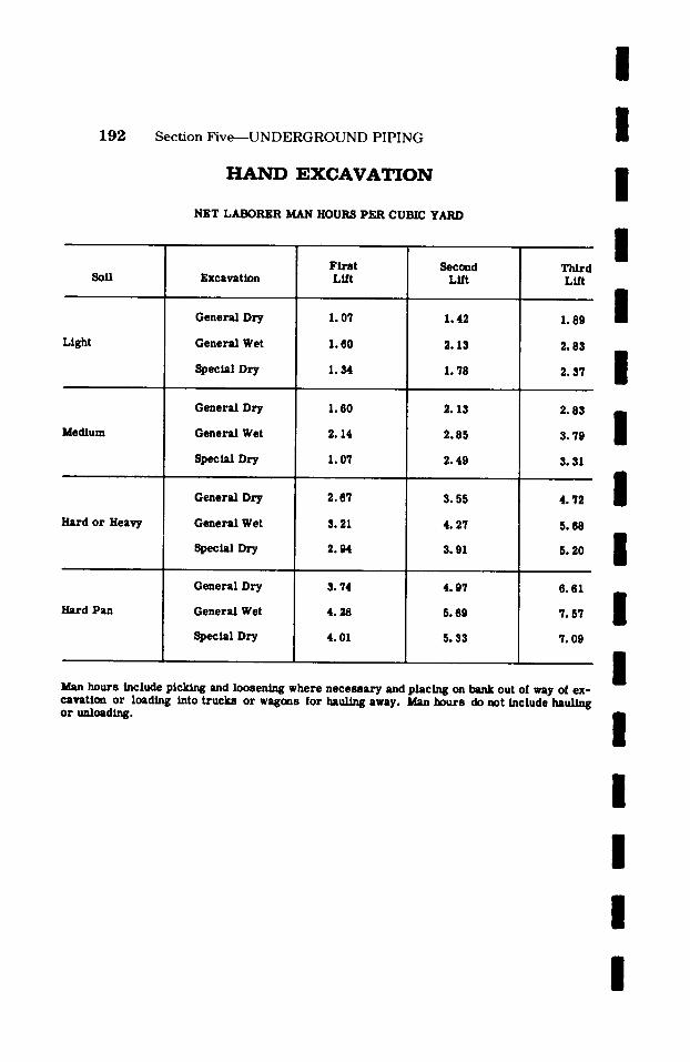
192 Section F ive- - -UNDERGROUND PIPING
E X C A V A T I O N
Soft
Light
Medium
Hard or Heavy
Hard Pan
NET LABORER MAN HOURS PER CUBIC YARD
Excavation
General Dry
General Wet
Special Dry
General Dry
General Wet
Spec~ Dry
General Dry
General Wet
Special Dry
General Dry
General Wet
Special Dry
Fi rs t Lift
1.07
1.60
1.34
1.60
2.14
1.07
2.67
3.21
2.94
3. 74
4 .28
4.01
Second Lift
1.42
2.13
1.78
2.13
2.85
2.49
3.55
4. 27
3.91
4.97
5. 89
5.33
Third LLR
1.89
2.83
2. 3'/
2.83
3.79
3.31
4. 72
5.68
5. 20
6.61
7.57
7. 09
Man hours include picking and loosening where necessary and placing on bank out of way of ex- cavation or loading into trucks or wagons for hauling away. Man hours do not include haul/rig or unloading.
I I I I I I I I I I I I I I I I

I I Sec t ion F i v e - - - U N D E R G R O U N D P I P I N G 193
I I
R O C K E X C A V A T I O N
Net Man Hours for Drilling, Blasting and Loading per Cubic Yard of Rock in Place in Ground
I / /
Operation
Hand Drill, Plug and Feathers
Hand Drill, Blasting
Machine Drill, Plug and Feathers
Machine Drill, Blasting
Soft
15.0
13.0
8 .0
4 .0
Labor Hours per Cubic Yard
Medium
21.0
16.0
11.0
6.0
Hard
30.0
22.0
14.0
7.0
Man hours are for above described operations only.
I For hauling see respective man hour page.
Equipment and materials must be added in all cases.
I I S H O R I N G A N D B R A C I N G T R E N C H E S
Net Man Hours per 100 Square Feet
I Operation
Placing
Removing
Laborers
3.0
2 .5
Carpenters
3.0
Truck Drivers
0 .4
0 .4
I Man hours include hauling, erecting and stripping.
I I I
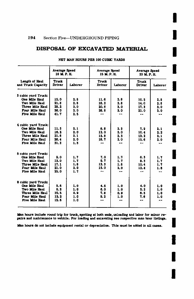
I 1 9 4 S e c t i o n F i v e - - - U N D E R G R O U N D P I P I N G I
D I S P O S A L O F EXCAVAT~L~ M A T ~ T .
NET MAN HOURS PER 100 CUBIC YARDS
Length of Haul md Truck Capacity
I cubic yard Truck: One Mile Haul Two Mile Haul Three Mile Haul Four Mile Haul Five Mile Haul
t cubic yard Truck: One Mile Haul Two Mile Haul Three Mile Haul Four Mile Haul Five Mile Haul
5 cubic yard Truck: One MAle Haul Two Mile Haul Three MAle Haul Four Mile Haul Five Mile Haul
B cubic yard Truck: One Mile Haul Two Mlle Haul Three MAle Haul Four MAle Haul Five Mile Haul
Average Speed 10 M.P.H.
Truck Driver Laborer
15.0 21.8 28.2 36.0 41.7
2.8 2.8 3.0 3.0 2.5
11.3 16.2 21.6 26.4 31.3
9.0 13.0 17.1 21.0 25.0
5.6 8.2
10.5 13.2 15.6
2.1 2 .0 2.1 2 .0 1.3
1.7 1.7 1.8 2.0 1.7
1.0 1.0 0.9 1.0 1.0
Average Speed 15 M.P.H.
Truck Driver
11.6 16.2 20. 6 26.8
8.8 12.0 15.8 18.1
7.0 9.7
12.3 15.0
4.8 6.0 7.8 9.2
Laborer
2.8 2.8 3.0 3.0
. . . . ,
2.3 2.0 2.3 2.0
. . , . .
1.7 1.7 1.8 2.0
1.0 1.0 0.9 1.0
Average Speed 20 M.P.H.
Truck Driver
10.5 14.0 17.3 21.0
7.9 10.4 13.2 15.6
6.3 8.3
10.4 12.4
4.0 5.2 6.5 7.6 . , . , , , . ,
Laborer
2.8 2.8 3.0 3.0
2.1 2 .2 2.1 2 .0
1.7 1.7 1.7 1.6
1.0 1.0 1.0 1.0
I I I I I I I I I I
Man hours include round trip for tnsck, spotUng at both ends, unloading and labor for minor re- pairs and maintenance to vehicle. For loading and excavating see respective man hour listings.
Man hours do not include equipment rental or depreciation. This must be added in all cases. I / I /
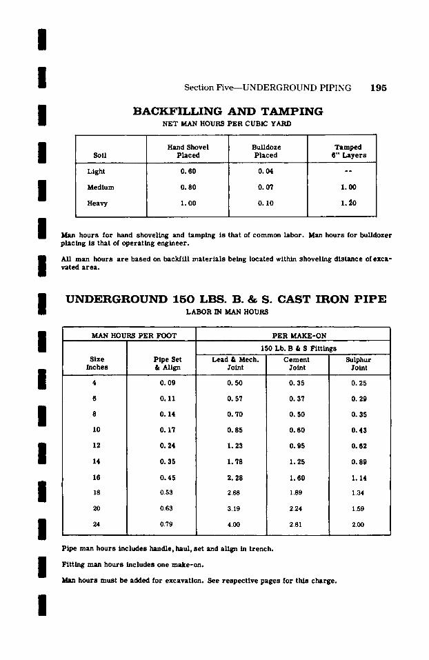
/ /
I Section Five--UNDERGROUND PIPING
B A C K F I I J . , I N G A N D T A M P I N G NET MAN HOURS PER CUBIC YARD
195
/
I
Soft
Light
Medium
Heavy
Hand Shovel Placed
0.60
0.80
I. 00
BuLldoze Placed
0.04
0.07
0.10
Tamped 6" Layers
1.00
1.~0
I I /
Man hours for hand shoveling and tamping is that of common labor. Man hours for bulldozer placing is that of operating engineer.
All man hours a re based on backfill mater ia l s being located within shoveling distance of exca- vated area .
U N D E R G R O U N D 1 5 0 L B S . B. & S. C A S T I R O N P I P E LABOR IN MAN HOURS
I I / /
I /
MAN HOURS PER FOOT PER MAKE-ON ,
Size Inches
. .
10
12
14
16
18
20
24
Pipe Set & Align
0. 09
0.11
0.14
0.17
Lead & Mech. Joint
0. 50
0.57
0. 70
0.85
150 Lb. B & S Fittings
Cement Joint
0.35
0. 37
0.50
0. 60
Sulphur Joint
0.25
O. 29
0.35
0.43
0.24
0.35
0.45
0.53
0.63
0.79
1.23
1.78
2.28
2.68
3.19
4.00
0.95
1.25
I. 60
1.89
2.24
2.81
0.62
0.89
1.14
1.34
1.59
200
/ /
Pipe man hours includes handle, haul, set and align in trench.
Fitting man hours includes one make-on.
hours must be added for excavation. See respect ive pages for this charge.
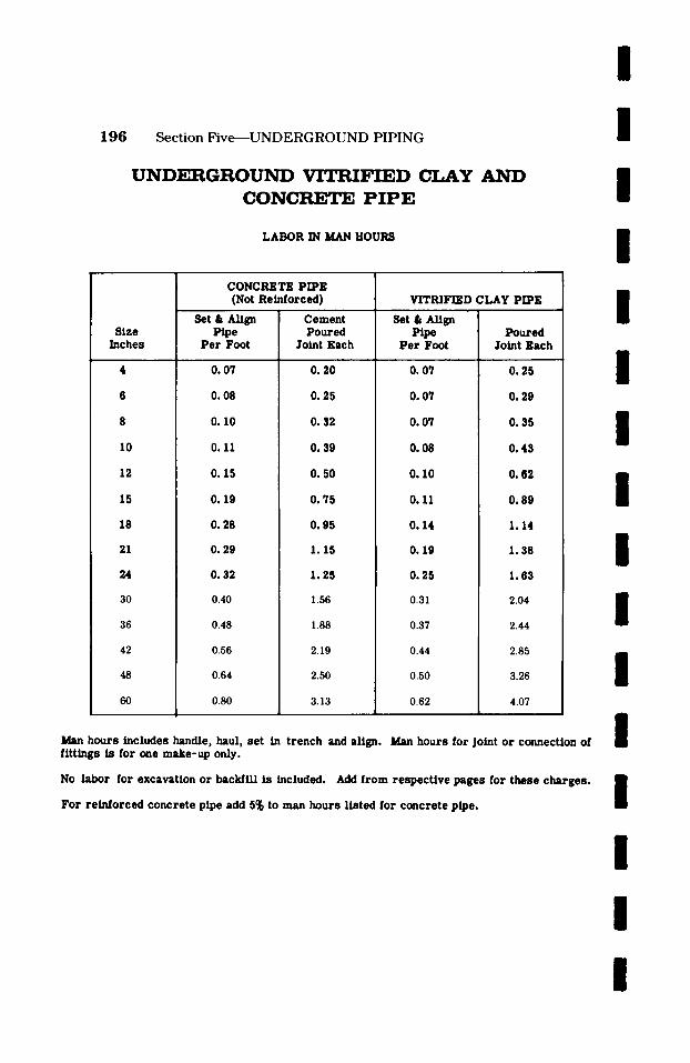
1 9 6 S e c t i o n F i v e - - - U N D E R G R O U N D P I P I N G
U N D E R G R O U N D V i T I ~ I F I E D CLAY A N D C O N C R E T E P I P E
LABOR IN MAN HOURS
I I I I
Size Inches
10
12
15
18
21
24
30
36
42
48
60
CONCRETE PIPE (Not Reinforced)
Set & Align Pipe
P e r Foot
0. 07
O. 08
0.10
Cement Poured
Joint Each
0. 20
0.25
0.32
VITRIFIED CLAY PIPE
Set & Align
P e r Foot
O. 07
O. 07
0.11
0.15
0.19
O. 28
0. 29
0.32
0.40
0.48
0.56
0.64
0.80
O. 39
O. 50
O. 75
0.95
1.15
1.25
1.56
1.88
2.19
2.50
3.13
0.07
O. 08
0.10
0.11
0.14
0.19
0.25
0.31
0.37
0.44
0.50
0.62
Poured Joint Each
0.25
O. 29
0.35
0.43
0.62
0.89
1.14
1.38
1.63
2.04
2.44
2.85
3.26
4.07
Man hours includes handle, haul, set in t rench and align. Man hours for Joint or connection of
/ /
I /
I /
I /
fittings is for one make-up only.
No labor for excavation or backfill is included. Add from respec t ive pages for these charges . /
I For re inforced concre te pipe add 5~ to man hours l is ted for concrete pipe.
/
I /

/
I I I / /
I / /
I
Section Five--UNDERGROUND PIPING 197
S O C K E T C L A M P S F O R C A S T I R O N P I P E
N E T LABOR IN MAN HOURS
Pipe F r i c t i o n Size C l a m p s
Inches Comple t e
4 . . . . . . . . . . . 0 . 2 5
6 . . . . . . . . . . . O. 28
8 . . . . . . . . . . . 0 . 3 3
10 . . . . . . . . . . . O. 38
12
14
16
18
20
24
Pos i t i ve C l a m p s
Comple t e
O. 30
0.33
O. 38
0.43
. . . . . . . . . . . 0 .45
. . . . . . . . . . . 0 .52
. . . . . . . . . . . O. 60
0 . 6 8 I �9 �9 �9 �9 �9 �9 �9 �9 �9 �9
. . . . . . . . . . 0. 75
. . . . . . . . . . O. 88
. . . . . . . . 0 .52
0 . 6 2 �9 �9 �9 �9 �9 �9 �9 �9
0 .75 . . . . . . . .
0 . 8 5 . . . . . . . .
. . . . . . . . 0 . 95
. . . . . . . . I. I0
Man hours a r e for l abor only and include handling, haul ing and the c o m p l e t e ins ta l la t ion in all cLses.
PIPE COATED W I T H TAR AND FIELD WRAPPED BY MACHINE
NET MAN HOURS PER LINEAL FOOT
I / I /
Nominal Pipe Size
3/4 1 1-1/4 1-1/2 2 2-1/2 3 4 5 6 8 10 12 14 16 18 20
Man Hours Per Foot
0.04 0.04 0.05 0.06 0.07 0.08 0.09 0.12 0.13 0.16 0.20 0.25 0.28 0.32 0.37 0.41 0.45
Nominal Pipe Size
22 24 26 28 3O 32 34 36 38 40 42 44 46 48 54 6O
. o
Man Hours Per Foot
0.50 0.54 0.59 0.63 0.68 0.73 0.78 0.82 0.87 0.91 0.96 1.00 1.05 I.I0 1.24 1.38
. .
I /
Man hours include: Sandblast commercially Apply one prime coat of pipeline primer Apply 3/32" pipeline enamel
Apply two ply of 15# tarred felt Apply one seal coat of pipeline enamel
For hand coating and wrapping add I00~ to above man hours.

S e c t i o n S i x
H A N G E R S
A N D
S U P P O R T S
I / / / /
The following table is intended to cover labor in man hours for the hanging and/or supporting of a process piping system.
It includes labor man hours for the installation of patented clevis, band, ring, expansion and trapeze types as well as fabricated hangers and supports made from structural angles, channels, etc.
In many cases, the drawings will not show hangers and supports but the specifications will state that they are to be fu rnkhed and installed by the contrac- tor. Thus, this becomes the estimator's problem for the purpose of bidding the job. You will find under Section Ten entitled "Technical Information" on pages 214 through 221, diagrams, tables, formulas and solutions as to how a process piping system should be hung and/or supported.
I I I / /
I /
198
I I I I

I /
I /
Section Six--HANGERS AND SUPPORTS 1 9 9
H A N G E R S A N D S U P P O R T S
Fabrication: Labor only for fabr ica t ion of o ther than s t andard manufac tu red h a n g e r s and sup- po r t s can be p e r f o r m e d at 0 .07 man hours pe r pound.
Field Erection:
I
I
I I I I I I
I
I
I
Type of Hanger
PATENT
~levis Hanger Band Hanger Ring Hanger Expansion Hanger
PATENT
t r a p e z e Hanger [ r - 4' Bar)
Hanger Suspended F r o m
Welded Clip Angle
CLip Angle - - Ramse t
F e m a l e Stud or Male Stud & Coupling - - Ramse t
F e m a l e Stud or Male _ Nelson Stud Welder Stud & C o u p l l n g
Beam Clamp or Corn CLamp
Cinch Anchor
Bolt o r St rap
Band and Rod
Man Hours P e r Hanger*
Hanger Fas t ened To
Concre te Ex i s t - o r ins
Steel Masonry Wood Pipe
1 . 5 0 - -
. 00 - -
. 6 0 . 6 0
. 6 0 - -
I . 30 - -
- - 2 .00
I. 60 - -
. . . . . . 1 .00
Welded CUp Angles 2 .00 - -
CLip Angle - - Ramse t 1 . 5 0 - -
F e m a l e Stud or Male _. Ramse t 1 .20 - - Stud & Coupling
F e m a l e Stud or Male _ NeLson Stud Welder 1 .20 - - Stud it CoupLing
Beam Clamp or Corn Clamp 2 .00 - -
Cinch Anchor - - 4 . 00
*The patent hanger allmmnces are for supporting p~pe through 4" size.
Fabricated ttmgers (Angles, Channels, Etc. ): O. 08 man hours pe r pound with a min imum t ime of 1 man hour r e g a r d l e s s of weight.
The following fac to rs should be applied for s i z e s over 4": 6" - - 1 .20 man hours 8" - - 1.50 man hours 10" - - 1 .80 man hours 12" - - 2 .20 man hours
I
S e c t i o n S e v e n
P A I N T I N G
This section deals solely with the sandblast ing
and painting of a piping sys tem and is so a r -
ranged as to include the direct man hours by
pipe size for six (6) different types or speci-
fications.
We have not covered color coding under this
section due to the fact that the scope of the work
involved in thls operation can vary so great ly.
As an example, you may be able to se t -up in one
location and band as many as a dozen lines, on
the other hand the same set -up may be required
to band one line. Therefore , we feel that this
operation must be Iooked at individually accord-
lng to piping specif icat ions and locations.
/ / / / / / / /
I / / /
200
I I I I
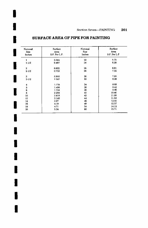
/ / /
Section Seven - -PAINTING
S U R F A C E A R E A OF P I P E F O R P A I N T I N G
201
I I I I I
Nominal Size
Inches
1 1-I/2
2 2-1/2
3 3-I/2
4 5 6 8 10 12 14 16 18 20
Surface Area
S.F. Per L.F.
0.344 0.497
0.622 0.753
0.916 1.047
1.178 1.456 1.734 2.258 2.810 3.142 3.67 4.19 4.71 5.24
Nominal Size
Inches
22 24
26 28
30 32
34 36 38 40 42 44 46 48 54 60
Surface Area
S.F. Per L.F.
5.75 6.28
6.81 7.32
7.85 8.38
8.89 9.42 9.96
10.46 II .00 11.52 12.03 12.57 14.13 15.71
I I I I I I I I

202 Section Seven--PAINTING
SAND BLAST A N D PAINT PIPE
COMMERCIAL BLAST
NET MAN HOURS PER LINEAL FOOT
l i l I
Nominal Size Inches
2 2-1/2
3 $-I12
4 5 6 8 10 12 14 16 18 20 22 24 26 28 30 32 34 36 38 40 42 44 46 48 54 60
4-Coats Conventional
Paint
0.05 0.05
0.08 0.07
0.08 0.09 0.10 0.13 0.16 0.18 0.19 0.22 0.25 0.28 0.31 0.34 0.37 0.40 0.42 0.45 0.48 0.50 0.53 0.56 0.59 0.62 0.64 0.65 0.73 0.85
4-Coats Chlorinated
Rubber
0.05 0.06
0.07 0.08
0.08 0.10 0.12 0.15 0.18 0.19 0.21 0.24 0.27 0.31 0.34 rs 0.40 0.43 0.46 0.49 0.52 0.56 0.59 0.62 0.65 0.68 0.71 0.72 0.87 0.93
4-Coats Vinyl Paint
0.06 0.08
0.09 0.I0
0.10 0.13 0.15 0.19 0.23 0.25 0.27 0.31 0.35 0.40 0.44 0.47 0.52 0.56 0.59 0.64 0.68 0.71 0.76 0.80 0.83 0.88 0.92 0.96 1.08 1.19
1-Coat Dimetcote
#3
0.05 0.07
0.08 0.09
0.10 0.11 0.13 0.17 0.20 0.21 0.24 0.27 0.31 0.34 0.38 0.42 0.46 0.49 0.52 0.56 0.60 0.63 0.67 O.70 0.74 0.77 0.81 0.84 0.95 1.05
5-Coats Epoxy Paint
0.08 0.10
0.12 0.13
0.14 0.17 0.19 0.24 0.29 0.32 0.35 0.40 0.45 0.50 0.55 0.60 0.65 0.70 0.75 0.80 0.85 0.90 0.95 1.00 1.06 1.10 1.15 1.20 1.35 1.51
1/16" Barretts
10-70
0.04 0.05
0.06 0.07
0.07 0.08 0.10 0.13 0.15 0.16 0.18 0.21 0.24 0.26 0.29 0.32 0.35 0.37 0.40 0.43 0.45 0.48 0.51 0.53 0.56 0.59 0.61 0.64 0.72 0.80
/ / / / / / I /
Man hours for painting pipe only. Labor for scaffolding must be added.
Man hours for galvanizing exterior of pipe only is approximately 80% of conventional paint.
Man hours to galvanize exterior and interior of pipe is approximately the same as dimetcote.
/ /
I /
/ / / / / / / / / / /
I / /
l l
S e c t i o n E i g h t
P A T E N T S C A F F O L D I N G
This section covers labor in man hours for the
erection and dismantling of patent tubular steel
type scaffolding.
In the p rocess of making the piping mater ia l
take-off, the est imator should give due consider-
ation to the lengths of run, the height, e tc . , so
that the number and height of sections of scaf-
folding may be determined for the entire piping
job.
We have not attempted to cover Job fabricated
homemade scaffolding due to the fact that this type of scaffolding for a piping job is so out-
rageously high. If this type of scaffolding is de-
s i red, you must look elsewhere or draw from
your past experience.
203

204 S e c t i o n E i g h t - - P A T E N T S C A F F O L D I N G
E R E C ~ A N D D I S M A N ' r v _ . ~
DIRECT LABOR - - MAN HOURS PER SECTION
Patent Tubular Steel Scaffolding - - 2" Planking Top. Sections - - 7' L x 5* W x 5' H
Includes: Transport ing scaffolding and mater ia ls from storage. Erection of scaffolding including leveling and securing. InstallaUon of 2" planking. Dismantling of scaffolding. Transport ing scaffolding and mater ia ls to s torage.
/ /
I / / /
One to two sections long
Three to five sections long
Six sections and more long
MAN HOURS PER SECTION
One or Two Sections High
Erect
1.40
0. 90
O. 70
Dismantle
1.00
0. 60
Total
2.40
1.50
0.40 1.10
More than Two Sections High
Erect Dismantle Total
1.70
1. O0
O. 90
1.20
0.70
2.90
1.70
0. 50 1.40
I / /
/ / / / / /
I

/ / / / /
p
l /
l l l l / / /
l
S e c t i o n N i n e
I N S U L A T I O N
The hardest of all piping i tems for which to try
to set a s tandard man hour ra te is insulation.
This is due largely to the fact that this is a very
special i tem which is usually subcontracted to
an organization who special izes in this field.
Too, an insulation contractor will consider many
factors before he submits his bid - - such as,
"Do I want or need this Job, is the Job large or
small , e t c . " The cost of moving in and setting
up is Just as great r ega rd le s s of the size of the
Job.
The man hours which appear in the following
tables a re the average of many Jobs and we
believe they will work fine for the types of in-
sulation they cover. However, we believe that for
projec ts where much and var ied insulation is to
be used a contractor who special izes in this type
of work should be consulted on this mat ter .
205

/
2 0 6 S e c t i o n N i n e - - I N S U L A T I O N I
thick- ness Inches
1.0
1.5
2 .5
3 .5
I N D O O R T H E R M A L T Y P E NET MAN HOURS
Pipe Size
1/2 .18 .28 .56 1.50 .75 1.50 i . 28 .18 3/4 .19 .29 .59 1.58 .79 1.58 .29 .19 1 .21 .31 .63 1.69 .84 1.69 .31 I .21 1 - 1 / 2 �9 24 �9 36 �9 72 1.92 i . 96 1.92 �9 36 �9 24 2 .25 .38 .76 2.04 1.02 2 .04 ! .38 .25 3 �9 31 �9 47 �9 94 2 .52 1.26 2.52 .47 �9 31 4 .37 .56 1.12 2 .99 1.49 2 .99 I .74 .37 6 �9 4 3 �9 6 4 1 . 2 9 3 . 4 5 1 . 7 2 3 . 4 5 �9 8 6 �9 43
1/2 .28 .43 .86 2 .30 1.15 2 .30 .43 .28 3/4 .30 .45 .90 2.42 ! 1.21 2.42 .45 . 30 1 .31 .47 .95 2 .54 1.27 2 .54 .47 .31 1 -1 /2 .35 �9 53 1.06 2.84 1.42 2.84 .53 .35 2 .37 �9 56 1.13 3.01 1 .50 3.01 �9 56 .37 3 .44 .66 1.34 3 .57 1.78 3 .57 .66 .44
4 .50 .76 1.52 4 .06 2.03 4 .06 1.01 .50 6 .57 .86 1.73 4 .63 2.31 4 .63 1.15 .57 8 . 67 1.01 2 .03 5.43 2.71 5.43 1.69 . 67 10 . 80 I. 21 2 .43 6 .48 3.24 6 .48 2 .02 . 80 12 . 91 1.36 2 .73 7 .30 3 .65 7 .30 2 .73 . 91
14 1.01 1.52 3 .05 8 .14 4 .07 8. 14 3 .05 1.01 16 1.14 1.71 3 .43 9. 15 4 .57 9 .15 4 .56 1.14 18 1.27 1.90 3 .80 10. 17 5.08 10. 17 6 .35 1. 27 20 1.39 2 .08 4 .17 11.13 5.56 11.13 6 .94 1 .39 24 1.62 2 .43 4 .87 12.99 6 .49 12.99 9 .74 1.62
1/2 �9 47 . 71 1.42 3 .79 I. 89 3 .79 �9 71 . 47 3 /4 �9 48 . 72 1 .45 3.88 I. 94 3.88 �9 72 �9 48 1 .50 �9 76 1.52 4 .06 2 .03 4 .06 �9 76 �9 50 1 -1 /2 �9 55 �9 82 1 .65 4 .41 2 .20 4 .41 �9 82 �9 55 2 .58 .87 1.74 4 .65 2.32 4 .65 i .87 .58 3 �9 68 1.02 2.04 5 .30 2.72 5. 30 1.02 �9 68
I
4 . 78 1.16 2 .33 6.21 3 .10 6.21 1.55 �9 78 6 .86 1.28 I 2 .58 6 .88 3.44 6 .88 1.72 .88 8 .97 1.46 ! 2 .93 7.81 3 .90 7.81 2 .43 .97
i J �9 �9 , o �9 .
1/2 .74 1.12 I 2 .24 6 .00 3 .00 6 .00 1.12 .74 3/4 .78 1.18 2 .36 6 .31 3. 15 6. 31 1.18 .78 1 .80 i 1 .20 2 .40 6 .42 3.21 6 .42 1 .20 . 80 1 -1 /2 .86 1.29 2 .59 6 .91 3.45 6.91 1.29 .86 2 .91 1.37 2 .74 7 .32 3.66 7 .32 1.37 .91 3 1.02 1.54 3 .08 8 .22 4 .11 8 .22 1.54 1.02 4 1.11 1.67 3 .34 8 .93 4 .46 8 .93 2 .23 1.11 6 1 . 2 1 1 . 8 1 3 . 6 3 9 . 6 9 4 . 8 4 9 . 6 9 2 . 4 2 1 . 2 1
l ' 8 1.35 2.03 4 .06 10.84 5.42 10.84 3 .38 I 1 .35
�9 - ,
Straight Bent F langes Valves Valves, F i t t ings F i t t ings Hangers lNozzles Pipe Pipe Line Flgd. S& W Flanged S & W Pipe ! p e r
p e r L F p e r L F p e r Ea. pe r Ea. p e r E a , p e r E a , p e r E a , p e r E a . Each
/
18 / . 1 9
24 25
.31
.37 �9 43~ /
�9 28 �9 30 .31 �9 35 /
37 44
�9 50 .57
.67 I 80 �9
1.01
~ .14 / 27
1�9
48 50
�9 55 �9 58 �9 68 / �9 7 8
�9 86 �9
7, l 78 80
.86
.91 1.02 / 1.11 1.21 1.35
/ Thermal Insulation: Cons i s t s of applying hydraul ic se t t ing, insula t ing cement by spray ing , b r u s h - ing, t rowel ing or palming, coat ing wttfi vinyl emuls ion , double wrapping with g lass f iber cloth and coat ing with vinyl emuls ion sea l coat�9
Outside Use: Add 10% to above man hours �9 Foamglass: Use s a m e man hours as appear above for this type insulat ion. This will include 1
labor for but te r joints with "Seal Koat" and s e c u r e with 16 and 14 gauge galvanized wire on / 9" cen t e r s � 9 F in i sh with one coat "Seal Koat" for indoor piping and 55# a s b e s t o s roofing felt s e c u r e d with 16 gauge wi re 6" on c e n t e r over the l aye r of "Seal Koat" on outs ldeptp ing .
Note: $ & W denotes screwed and weldea. /
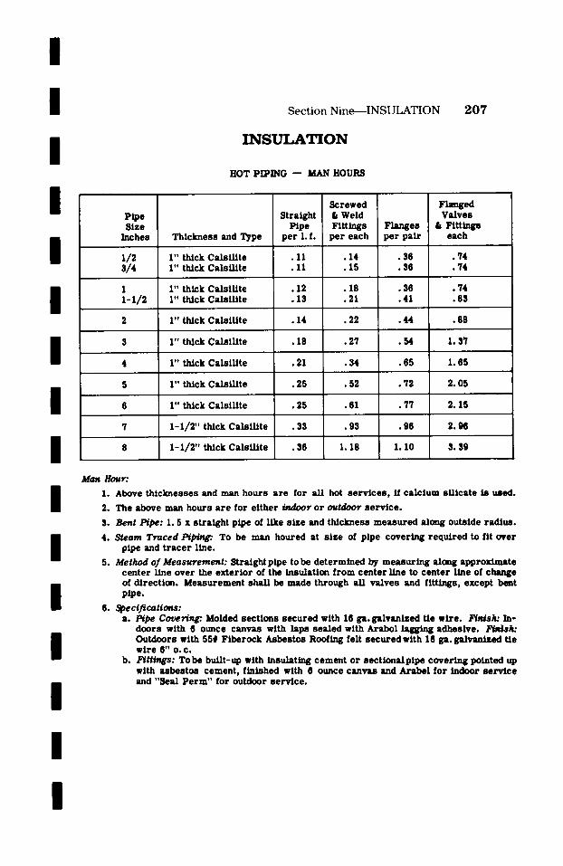
/
/
/
/
/
/
/
/ / / / / /
I
S e c t i o n N i n e - - - I N S U L A T I O N
I N S U L A T I O N
2 0 7
HOT PIPING - - MAN HOURS
Pipe S i z e
Inches
3/4
1 1-1/2
Thickness and Type
I" thick Cals i l l te I" thick Cals l l l te
I " th/ck Cals l l l te I" thick Cals l l l te
I " thick Cals l l l te
1" thick Cals i l / te
1" th/ck CalsiI l te
1" thick CalsUlte
1" thlck Cais i l l te
1-1/2" thick Cals l l l te
1-1/2" tbAck Cals i l i te
Straight Pipe
pe r l . f .
.11
.11
.12
.13
. 1 4
Screwed & Weld Fitt ings
pe r each
.14
.15
.18
.21
�9 22
�9 18 . 2 7
. 2 1 . 3 4 t
. 25 .52 !
. 25 .61 |
�9 33 . 9 3
�9 36 1 . 1 8
Flanges pe r pa i r
�9 36 �9 36
. 3 6
.41
. 4 4
. 5 4
. 6 5
�9 72
. 7 7
. 9 6
1.10
F~mged Valves
t Fittings each
. 7 4
. 7 4
. 7 4
. 8 3
.88
1.37
1.65
2. 05
2 .15
2 . 9 e
3.39
Man Hour:
1. Above th /cknesses and man hours a r e for al l hot s e rv i ce s , ff ca lc ium s i l ica te is used.
2. The above man hours a r e for e i ther b u h ~ r or outdoor se rv ice .
3. Bent Pipe: I. 5 x s t ra ight pipe of llke s ize and thickness m e a s u r e d along outside radlus .
4. Steam Traced I ~ ~ To be man houred at s ize of pipe covering r equ i l ed to flt over pipe and t r a c e r Line.
5. Method of Measurement: Straight pipe to be de te rmined by measur ing along approximate cen te r line over the ex te r io r of the insulation from cen te r Line to cen te r line of change of dh 'ect ion. Measurement shal l be made through al l va lves and f i t U n ~ , except bent pipe.
6. Specifications: a. /~pe Covering: Molded sect ions s ecu red with 16 ga. galvanized Ue wile . F i ~ k : In-
doors with 6 ounce canvas with laps sea led with Arabol lagging adhesive. Fbds/t : Outdoors with 55# Flberock Asbestos Roofing felt s ecu red with 16 ga. galvanized tle wi le 6" O.C.
b. F ~ ~ : TO be built-up with insulating cement or sectlonalpipe covering pointed up with asbestos cement, finished with 6 ounce canvas and Arabel for indoor service and "Seal Perm" for outdoor service.
I
I
/
S e c t i o n T e n
S A M P L E
E S T I M A T E
/
/
/
This section is presented for the purpose of showing the
work ability of a few of the man hour char ts as appear
throughout this manual. It does not mean that a take-off
must be made in this manner before the man hour charts
will work. It is merely a suggested method.
I
I
I You will note on the following take-off sheets at the top of
the page a predetermined composite rate, a r r ived at as out- n
lined in the Introduction of this manual. Simply by multiply- [ Ing this composite ra te by the total man hours Involved, a
total est imated direct labor dollar value can be easily and n accurately obtained. [
We do not show in this sample est imate any mater ia l cost, n
nevertheless , you will find ample space provided for this $ item. You will also find space provided for both unit and
total weights of pipe and fittings. We feel that this item has n
much value such as an est imate check using the weight $ method, or for the estimation of warehousing, equipment
usage and fabrication shop set-up.
We purposely have not included material , miscellaneous
supplies, equipment usage, overhead and profit in this est i-
mate. As is stated in the Preface of this manual, its sole
purpose is for the estimation of direct labor in man hours
only.
/
/
/
208
[
[
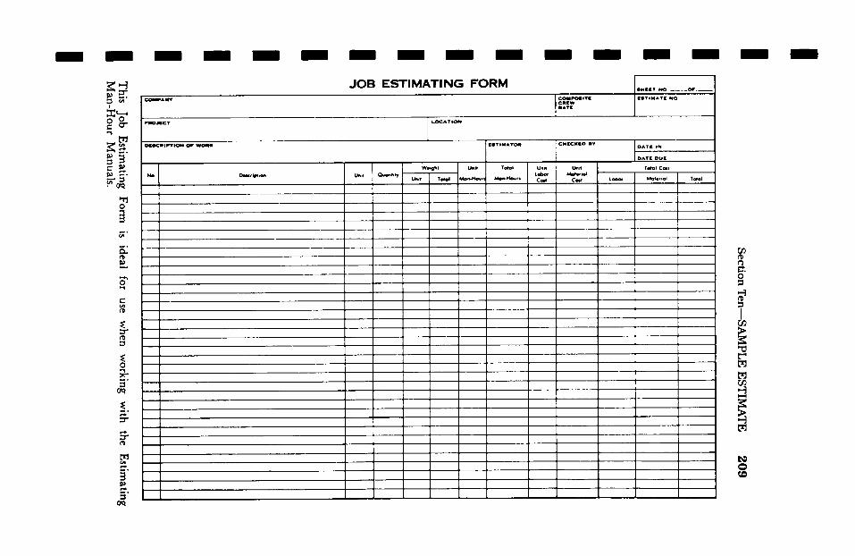
l / /-Y
!i
/ /
O
Ig
/ ~ Z
/
UO
I
[
il~J i
o
�9 ,ff
Section T
en---SA
MP
LE
ES
TIM
AT
E
20
9
l / / U i
This
Job E
stimating
Form
is
ideal for
use w
hen w
orking w
ith the
Estim
ating M
an-Hour
Manuals.
/
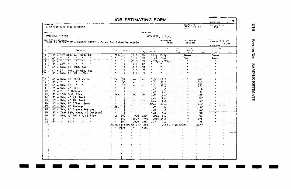
/
21
0
Section
Ten
--SA
MP
LE
ES
TIM
AT
E
I
o
:E E 0 h L~ z m F-
:E .I I- I/I b.l
m 0 "-I
o
i
Pt
o1I~1 uuil
0 0
u
o
C
I
co
::z: II.,
I ~'~
g ~
g~
~ -
~~
~
~,
~~
i~
l~
~'
~~
u �9
~ z
r..l '. I'~ .Lr,'~ -,,? I~'~ i,,~ IL'-. .~0 <:~, ;~
il~l ,-I ,--I ,--] I,-I i,--I I,,-II,'-I I,--I I I~/;
(~ ,
1 1
l 1
; 1_
r: �9
j .
..
.
I 1
1 i
1 1
. 1
" "/"
:
' i
i ,
, ,
I
': i
, ,,
, ,
. .
,
,~" I:
I~ :=
,= =
II~ !,.
k i.
!- I~
i1~ i~
!- !.,
!. I~
I~
Z,~ I
: I
' I
I �9
' '
~ '
' l
! '
i .
, ,
,. ,
i '
i I
, ,
I "
. '
I ~ ..i~
! '
�9 .
i .~o.~~
.~.~=.~..~ ~I~
~i ,,o
,~, ~o',,~
r- r,-
. r-4'
.~: i !:
' ~
i '
= ~
= =
,= ,~
= In=
=i =
I= "
' I
' ;
t '
. '
i i
' ~
, i,,
: ~
. ..
i ~I
i i. 1 ~'
i i
.1"~ �9
'1,
~ ::
i i
, '(.,,,(~ ~,~
,~,~i4~io ,.~
~ :
I~. o ~: ~io~ ,,,,,,,
~~
~
~1~,~~ �
9 '"~
" ..... :
['' :i
i" ~
" ~
' .~
,,,t..." ..........
o~ ,
~,.~
..~.~
,~
.~ ~.~ .~
',~~
. �9
el �9
o' e:
i, '
;:~ H
:)1= ~-
�9 ;.
..
..
..
..
..
.
~ �9
.~, 1
. .
�9 I ~-.
�9 ;
..
..
..
..
.
~o~~"~ i
~,I i '''I~
'~'~~
' P~'
~' '
I '
' "
T ~
' '
~ "'"
, ,
i '~
; .
! '
. '
' I
i ~i~,~
~ (~
(~ ~
H,~IH ~
~ '
"~'
::'''.'' i!l,::'i'.~
': ,~,.!~-
i ...........
'~ '
i~ ,.
~ '
~,: ~
~:,= '
= =
= ,-
,. =.
~= =.,-,,-
~.:=i,= ,
= =
...~.. :,...
;.1, ,
.... .~
, ....
i
' i
: ,.
�9 .
~ .
. I() ipt
' tli .i~:
,f=.1 I~'
I~ ;
"tO ,.-4
I
"ID '
IP ~
�9 "lli'll.lZ~=
ill:: I
'll'C'. ,~=
= i~.~
I~I~ ~.1:
I) I~
: '
o'=
[= =
~ ~
.~ .
~1
~
�9 '.-.'�
9 ~--~~.
-,,1' :
_~ ~
m
(D
~ .W
'~uO ~
]r-,l~ la.
: "
~" /
,,.,~ M'IO',!O
~l~lg ~'=
-~ :
�9 o
~c
o ool~-ioc'oo'o%o'
,o' o,
I=, :~ ~
~=
.~: -,~I~ r~
.~.~I~0 ...~
0 ~"
�9 J:
el �9
o0
~
"~.O
lO,It~
tlill t~
II:=i=
!
~1
~
;11~' ",,~' 0"} �9 ('~(,/") (/"J I~
re'i(/'} ,I= .=,4'l/~ll/~
I/) l/)
{/} ~'~
l,
/~
',
i.
' I
I I',I
I I
I,( I
I I
I'I'I ;
I I
I I
I I"
I I I,
I', I'
.,~ ~::) I
..
..
..
.
I 1'" / / / / / / I / / / / / / /
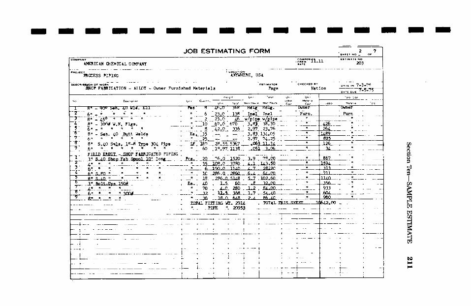
/ / Section
Ten--SA
MP
LE
E
STIM
AT
E
211
I I I I I I I I I I I I I
lj ~ i
o I J..
LO z m l- ,d:
I-
i,I
m 0 -)
i
, b
"" "
, I..
= =
t 1
'
o. ;"
=. ~I
=
:::) u
t:i
t '
,
5~~ !
' i
I .
; +
i T
t +
I '
i I
_ '
~ ".,I
,~.~~ .-,
c ~
~.-~l-~,p,~,,,~C~/I ~.
.~. !~'
:,. l
. ~
~t..:] l.,,i
' !~- ~"
o ,~ c,~
.,,?I 0 '
I,
~1 :
'~ / ~'-'
~' .,
! 1
~ T,~c,.,
I ~
;~'~
",~
,'~
I I'~
~ J
�9 +
, +
' �9
I ]
�9 ..-
~ ,J
I
o .,-~
' r,.% r,,~, 0o- ,,c)
t ',
I ,
, I~
�9 ; ~,
,~ ;
~ ~
IO '
. '
IO ' ~'
- =
= -=
"s: "[z)
: '~-~--
�9
/
!
a.'. : -=
l: "r-4
=" ac
.~ ':
'|
::: -'
= k~O=
,~ s~
= ~,
,-.4 +.)'
"
I, I
I I,
I
1:11: l...
s: s:
=" I:
=
. I
'ji l'
i I~:~'~ :
i ~
: i
' ,
i '
' /
! ii
L '
i /
�9 '
i .
; ,
i I i
, ,I
,
�9 '
I !
! i
�9 ,.
.--~-..
, '
! I
o~ ,.-
c,, -,,'t ~
a. N
I~ "-~'
/ I
I
c'~, '''
..
..
..
..
O
, i
! ,
~ ~
. I
!,~ i
'
~,~.! ~'~*=,':
,: '
' "t
" " !
"' "-
'~i ,
' ~
' i
.. ;
+; ~ .
..
..
..
..
.
:.. ........
i
a~ ....
t
li 50,., tc
I S:
I:
i i
i I
j i
, I
_4._ ~
..
..
..
..
..
1 1
, i
i
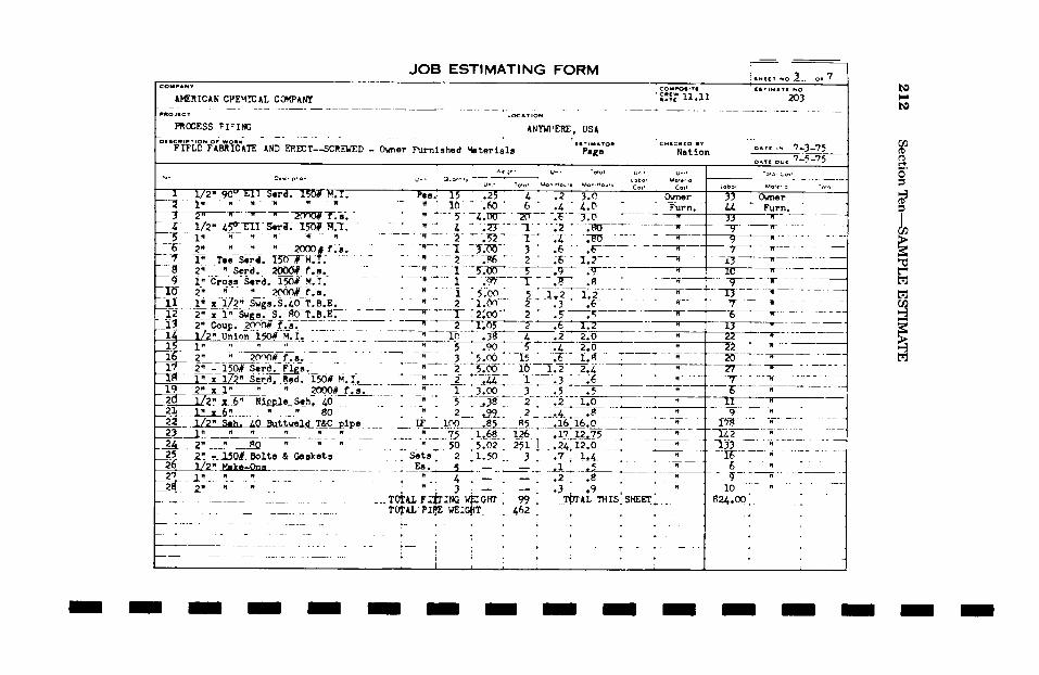
/
212 S
ection
Ten
--SA
MP
LE
E
ST
IMA
TE
/
II ,41,. 8
~ Ij :: ,q
uuI
~r,
z_
.~o ~
u
n' 0 b.
o Z n i-
ra
I- ul bJ
m
0 =1
.,w
o ~
" ~
m I
r
I..ir
t ,
I i
:
�9 i
' !
" I
I ,
I !1~
i' '
i i
!
I ,
. '
"
!i,,: I ........
! i
i
ii i
8 !~
I: i r
:=
l: I~
t: I=
i 1
. ~
�9 �9
'. .
..
..
,.
~, ~,~~o~oo �9
ti!i'tli- ti I i!J"
~iz r
..
..
..
,
. ,
�9 :
.
i i
I '
|
~~
,~,,b,
~.~
o~,o1~,o'~-~
~. '
C~.~
,. ,~
�9 �9
,. ,~,
~ �9
�9 ~r
'~';,~i . ~ ,~, ; "~ir "~ "'~:"~'~""
"" !
, ,=-41,-4' ,.=4 '
[..-, ~ ;
~ '.,-. ~
. .~.
....... -,4'
I ~ ,'~'~,~.,,,,,~
~ c',~'l,-
,~'e~ ~
i . :..,
..... .. .
..
.
.~........, .:
./..... :4 �9 �9
, I
I '-';/
' "'
i ~''i
! '
' T ',
*' '
~ '
L. �9 t
! !.i
; .....
! ........... .
. ;H:.,-~'
~ .El~i~
. I
I I
(~,s
; r
, .:ii~ii'.~/
' i.
"~ /
i!~
;~
.~
..
'.~
.
..
..
..
..
J
'~ :~i~o
~~~~_~,~~ g,~,:~J~~,~,,,~o,,,,,,
} 1'
~ t
~ t
i *
. 4-
�9 ~
* �9
t .
..
..
.
..
..
..
..
..
,,,c. i,,, ~.~ ~ ~, ;-.,,,-,,,-, ,,, I,-,
"':'","".. I'-'i"' (',, ~:.~o
..... ,',, ,,~ ~,",.q, i~=..,
,-4r-~, .
! ;
. I
i ~
, I
- ,.-t:
; .
/ "
H .
" I
! I
�9 '
�9 i
, '
�9 ,.
.i
l,
,
..
..
~
. '
t ~,
"'"
~*
........ ~"
.............
I
J �9
!
�9 ,,,,4
d.,-: ,,; ~i~ .~
, a
i.d .:~
I ~',*i
�9 ~
' 0'~
"f-~',,-4 ;~.~
~-I
z: -
" NI Ig
I I
"'" I
i
"" i
~..
, ..... .4
.§ !
/ I / / / / / / I / / / / /
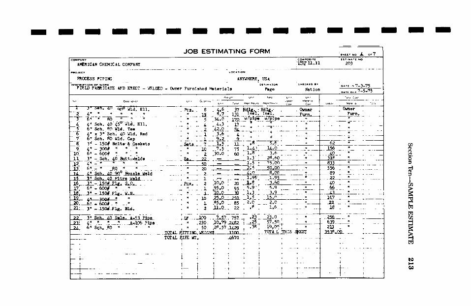
/ / S
ection
T
en--S
AM
PL
E
ES
TIM
AT
E
213
/ / / / I I / / / / / / I
o o~
I[ ~; i:
w 0 I, 0 z m
I-- < I- (/) bJ
m 0 ,-)
�9 t'.,1
" .
~ I
:"-' |
| =
I m
" t,...1
10 �9
~ ,a
"t: "
�9 : ~,t
m '
~1 ~' I=
~1,'~
. .~4.['-'.
3l~(,...1 Q,~'
4,.): I
Ol
~ =
i I~
~. -~'
_ �9 ~'
= '~1
I .~.,.J
~ e"~
~ ,m
t~
' I~
C~ '0
: "
�9 r__,,' *
~ ~1:
It: Ik
I I:
O '~
.<I"~ a,
d~l I
o r
,I ,
*
!:,~ "1 ',.~."
.'::,"" '-'~ - - 'o;'
Io8,' "'~: .-~,,
~' -, ,,. ~
.~~
.,~
,~..
. .~
.~
, O
, .,~
~ ,
.... :.,.~
.o, .,~
i1~
. .
,
i l
" '
-,,,0 -4,0
,-, -4.,0
,,',,-,',~ --z,"
~I,o','~ ~
,'*
' :
+ "
~ I
: ~..,,,.~,,-:,,,,,.. o.,-,,,,,,~ J J.,,f,..~4-,,~ ~
i ~ .~
r i
', ,
, ,-~,,-~i,-~,-~,-~,-~,-~,-~,-~,-~e~
I :
l �9 :.
I I
I i
t '.
,l
ll
l
!I
ll
o I
l-i ItJ
::Z:: I~
Ot-~
,~ ~
z ~,
u i
�9 '
i !
:1 ;
::'''' ;'-'
..
..
..
..
..
.
J .
, i
.~ ,
; ~
;, r
;
";'" ~o
,~i: .'.
:i. i
' : '~:'''''
~ ~
",
~
~ I
! :
I '.
I I
i .
.
I 8
. .
: '
'~
l~
,,
~
. �9
:/~ ~.
" ~
: '
: J
: :
i'
I 1~
,' II,
1 l~';!~i~:::::;'i
~- o~
"~- ~
i "
I ,
, i
- I
; i
, "
- ,
~,
~
" '
I �9
I '
, :
'
= =:~-,j
i :
I
~': ~.r~.:,
,,.' Itl'~i' ~":
t' ....
l.~:.:.k'--L-- -.~
, I
' '
. ',
' '
' ~
I '
'
~~ i
i: !=
, ,iiJ'li
I' ~
: .
,__._.. .
. ..
, ,,4!
t "+-'~
" ,, ,,
.~r .~
",-/" '
'~ .4,..,
. ~,-- ~-.
�9 ,~ o
~1 '
"~' ',
.... ~:
"1,.;.~~.4 "~;.
4.,.,,,~: '
" "'
"'~ ~
. "~1~..~,
' "
" "
' '
' '
='; =
,,
'
/I., /
: =
' !
- .~
-!~).
.t~..~
,. "~
{T
~'
~.''
;~'
;~
...................... I
-- _~
u,, ~
, ~c
".,*l~c ~ ~:v,
c!o',.~c,o, ~v,
o t~
:,~:.~c '-.
" ~:.~"
............... .t ......
.' �9
�9 �9
'~.~.~. :
-" ~
.~-,'-. ',
i .~,~
,-~'~,~1~ ~,,r.,
~n~ ~
- ~
~,--, 'd
..., '
~ '
,I ,;
,,4 ,,",
i~ a
- ,...,~~,~
~,...~ ,/t!l, ~:~~:~,,:,~ ,,,,~~l,..
"~ -.
e.- / '
oi,,0 ~
o. i
i i
olo.o,o:oo .....
....... I
' '~"
~" '
'~c~ ,
| i
-,,~ -, -, o, ' ,-, o, I ~ ~- o I
I l:
ii I o~oI~,-,
i �9 ,
.... ,
! ......
{1
.. ~
."~
."t- r
....... ~ ........
~:t O
I O
~
~ ._,
,_, ,,.,.,,
. .
. t~.,,,.,~,
.... . .... ,
..... =
a ,
, ,,
; :
~ ,
, ,
. "I
' '
'~ ~
'' '~
~ I ~
~
.... I
: '
i �9
I
~ t
!,i '
-4 t:
i: t~;
"4 12
i i
~'~, ,
:
" -
i '~
..
..
..i-
..
..
/
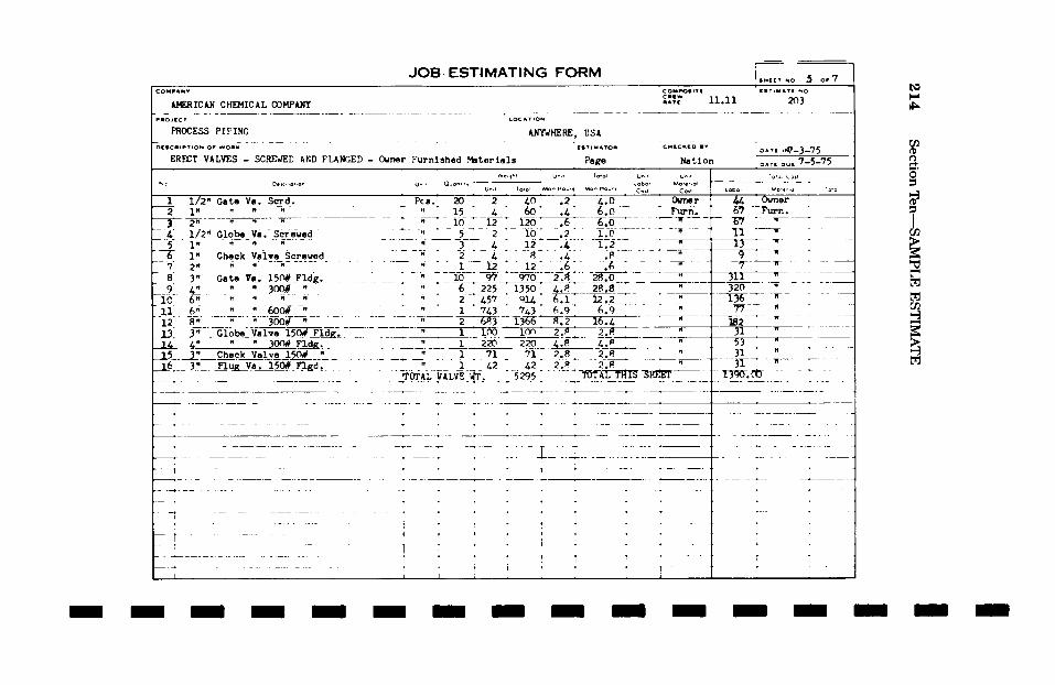
/
214 Section
Ten---SAM
PLE ESTIM
ATE
I
IJ.
b.I
m 0 -I
! i
i J
i I
" :
l '
I ,
.', ~,'t
, ,
�9 , .....
~ ,
, ,
~ ,
1 ,
, ;
+ ;-
i .
..
..
..
.
o '?"
~ :
, ',
I '
' '
o~ ~
~ Ji~.,...,
: :
~ i
�9 <~.
/i' I
I: '
. :
. '
' .
, '
: ..
, i
, I
i I
I t
i i
; .
. t
I~t i
. +
~ �9 i
�9 �9 :
.... ; ....
'
I , ~
,~D, I~
~,~,,,,~ +
. "
o I
i I
!
�9 '~
7~ L,
�9 t
' I
'. io
.,~ ~
~ :~
: '
i :
I !
l[i ~
"~ ,,il,
l~,i~
~+~ "
" '""
~ ~.,.. ~._ .,,.. !
T i :"
0 c/olo'~:~
o,~'e~ a', ~
" ~/+e/ou I
- ~
�9
.....
'.
-'
..
.~
t
! i
!
II I
' '
�9 ,
' -
I '
I
) ~
-.4~ ~'.,,~'.,4.,o!~,~
,.-4 o, e~Ll~
~.~, �9
:~ I,
" "1"~
"~ ".
": "!d'41~'gl='!di4
d'd} "
+ +++~, ~ +;:, .m++:,.+:, i i
"~ ~
~ :~
~ ~
u'~ ~
,C
~
~ :
I ',',, ~'~
,,,., ,-,' ~ �9
, ,
. i
,' !
' "
+ t
I '
! i
i t
" |
t f
" ~'+
i .
..
..
..
..
..
..
..
:"
o ,,.,to
.,,., ,-.,'.,.+ ,-, oh:>,.,, ,--,I,-,, ,-, ,.-, ,-,.,-,
+.,,' "~
+' '+" "'"-'.
' '
i"! -
' I
. '~
'
~ +
~... '
' I
' '
' �9
I '<
' l+
I .'t'
" '+
[ i
+~.,+ .
..
..
..
..
..
..
..
..
.
- __
. .~,.,.
....... =i=~=
i. ,
! �9
~ ~
=1~,= .
,
~ "
+ "i
~I ~
: u
,, i!!
t +~i'
t .
..
..
..
..
..
..
..
.
<~ '
I '
I t, i
0 I
~ I i
t~
o ,-,
~ en u
j~ j
I
+.
!�9 ~
:
, '
~ ~
~ ~
;
�9 ,;
-.
.
. ~;~.3
i'
t- O
's: @
'= 4,~
" =
=: =
, 0 r
�9 I
�9 ,
i 1
,.-4 I~ t~'~'.m
~ '~
"e0' ~i o',-4'
e~'~ "
"- "
r ...... ~
- i.
"~ "~ "~ ~
, ,
I '
/ / / i / / / / / / / / / /
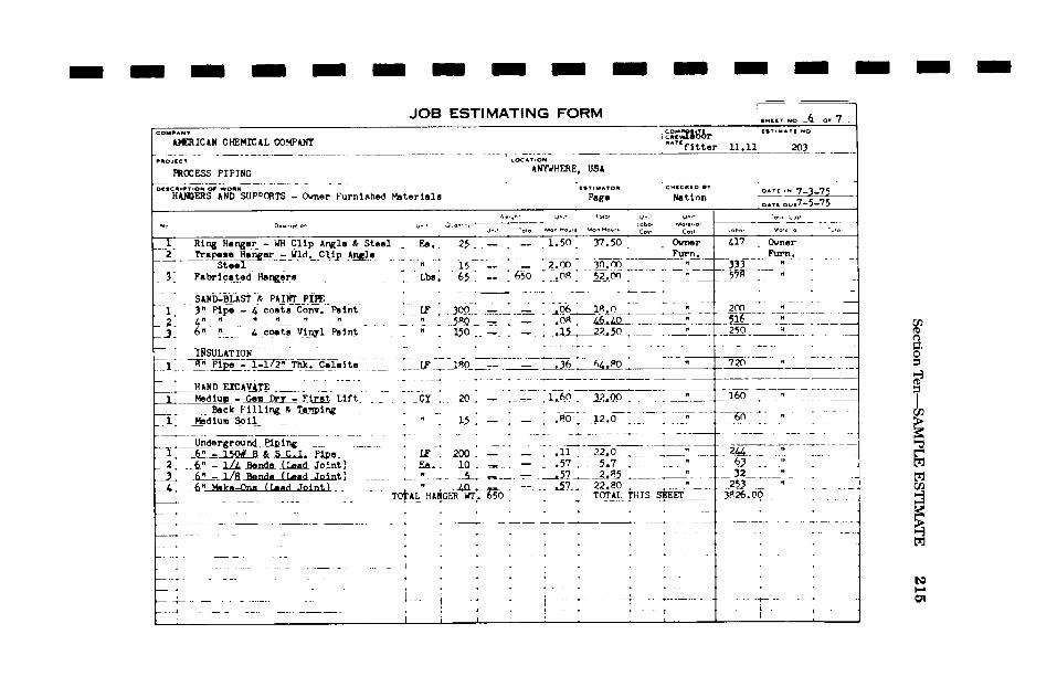
i / S
ection
Ten
--SA
MP
LE
E
ST
IMA
TE
215
/ / / I / / / i I / / i / I'l o
o i
4
iL: ,
z m
I-
ra 0
.. ~
I i i i @
i .
'i .
i !
' �9
, .
. ,
. i
! .
�9 '
I ~
~1 ~ .~
, ;
, ~
t
~~ ~#~
~"
i
I :
I i i i i
: I
: ,
, t
i .
i !
1,,,, t
, ,
i
i~~, ~
, ,
, '
I '
~ i
; I
�9 �9
~ J
�9 i
, ,
, :
.i .
..
..
..
..
I i
:: !!oi
...... ;_~_
~i~l~,~ i~ I
' I
i' ~i~i ,~
..
..
..
.
, .
i
~i~' "" "c,~, ~
I~ }'~" I~.o~o,
~..~ ......... : ~i
~~~ I~~ ~'
i ]
I 1.:,
, ........
;---
I '
i ~
" .
I I.~
I I
I ~ I
.I, I
' 'IIII
i ,
, H
i
�9 lt''t ~ ....
i'''' ...........
, !
:1 t
I
,,,.. ..i
i .
..
.
i ~,~ u"~ ~-~
~ '
'.i~ '
�9 �9
t i
" ,
: ~ i
~ t ~
,' ~
' '
~ t~
�9 ~
, i
, ~
. '
t ,
~. j
I ',
. �9 ~
... ~
~: .
..
..
..
..
.
i
| "~
~o ~,
.~
: )i
i ['~i
' Il[''i
:
;'~;'-,d" s~
,,,,? .,,II
r-~.,-4,
I I ' '9r
'(,I., @
3 �9
I ~, '~411Zl"
"~
~r~ - ~,~ -,,?',,~D ,~-~
-~',~1 H ', ,~~,4,
,-~, i-~
,~',
(-.,
i !
I ,
! ! ~
~1 ,
: .
I
[ ~..t~'.J.~
i" T t'
' -~~
/
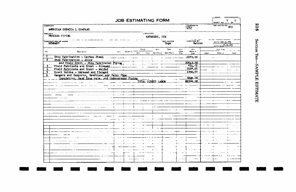
I
216
O
Z
m
b-
W
m
O
[J3 .
,j
i ..... 4 S
ection
Ten----~C
~AM
PLE
ES
TIM
AT
E
/ /
i il
lii ,
I
i i
I :
I
" "
/
I '
/ �9
.-~ 4.
-I- ...... 4---t --~
i! I|
,i,
' I
i '
I
/ / / I /
I / / S e c t i o n E l e v e n
T E C H N I C A L / I N F O R M A T I O N
I I I
I I I I I
As we stated in the Preface of this book, its intention is solely for
the estimation of labor and is not intended for the design of pip-
ing. Therefore, this section has been held to a minimum and
includes only information that we feel will benefit the estimator
in the preparation of his estimate.
Included in this section are tables showing the circumferences of
pipes for welding purposes, the amount of materials needed for
insulation, the weights ofpipe, fittings and valves and methods of
hanging and supporting pipe and fittings.
We wish to acknowledge and to express our appreciation to the
Grinnell Company, Inc., of Providence, Rhode Island, who has so
graciously allowed us to reproduce the following tables.
/
/
/
l 217
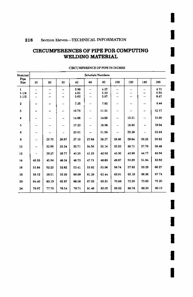
218 S e c t i o n E l e v e n - - T E C H N I C A L I N F O R M A T I O N
CIRCUMFERENCES OF PIPE FOR COMPUTING WELDING MATERIAL
CIRCUMFERENCE OF PIPE IN INCHES
/ /
I /
Nominal Pipe Size
1 1-1/4 1-1/2
I0
12
Schedule Numbers
20 30 40 60 80 100 120 140 160
3.98 -- 4.27 4.81 -- 5.13 5.62 -- 5.97
7.25 -- 7.65
10.78 -- 11.31
14.06 -- 14.68
17.33 -- 18.06
20.61 -- 21.56
15.31
18.85
22.38
4.71 5.50 6.47
8.44
12.17
15.90
19.64
22.44
26.70 26.87 27.16 27.68 28.27 28.86 29.64 30.23 30.83
32.99 33.34 33.71 34.56 35.14 35.93 36.71 37.70 38.48
39.27 39.77 40.25 41.23 42.02 43.00 43.98 44.77 45.94
14 45.55 45.94 46.34 46.73 47.71 48.69 49.87 50.85 51.84 52.82
16 51.84 52.23 52.62 53.41 53.82 55.56 56.74 57.92 59.29 60.27
18 58.12 58.51 59.29 60.09 61.26 62.44 63.81 65.19 66.36 67.74
20 64.40 65.19 65.97 66.56 67.93 69.31 70.88 72.26 73.83 75.20
24 76.97 77.75 78.54 79.71 81.48 83.05 85.02 86.78 88.35 i 90.12
/
/
/ / / /
I /
/
/ /
/

I /
I
I
Section Eleven--TECHNICAL INFORMATION
C I R C U M F E R E N C E S O F H E A V Y W A L L P I P E ' F O R C O M P U T I N G W E L D I N G M A T E R I A L
CIRCUMFERENCE OF PIPE IN INCHES
2 1 9
I /
I I /
/ /
I / /
I
Nominal : Pipe
Size
Wall Thickness in Inches
�9 500 .750 1.00 1.25 1.50 1.75 2.00 2.25
3 12.57 14.14 15.71 17.28 18.85 20.42 21.99 23.56 4 15.71 17.28 18.85 20.42 21.99 23.56 25.13 26.70 5 18.85 20.42 21.99 23.56 25.13 26.70 28.27 29.85 6 21.99 23.56 25.13 26.70 28.27 29.85 31.42 32.99 8 28.27 29.85 31.42 32.99 34.56 36.13 37.70 39.27 10 34.56 36.13 37.70 39.27 40.84 42.41 43.98 45.55 12 40.84 42.41 43.98 45.55 47.12 48.69 50.27 51.84 14 47.12 48.69 50.27 51.84 53.41 54.98 56.55 58.12 16 53.41 54.98 56.55 58.12 59.69 61.26 62.83 64.40 ~8 59.69 61.26 62.83 64.40 65.97 67.54 69.12 70.69 20 65.97 67.54 69.12 70.69 72.26 73.83 75.40 76.37 22 72.26 73.83 75.4C 76.97 78.54 80.11 81.68 83.25 24 78.54 80.11 81.68 83.25 84.82 86.39 87.96 89.54
2.50 2.75 3.00 3.25 3.50 3.75 4.00 4.25
10 47.12 48.69 50.27 51.84 53.41 54.98 56.55 58.12 12 53.41 54.98 56.55 58.12 59.69 61.26 62.83 64.40 14 59.69 61.26 62.83 64.40 65.97 67.54 69.12 70.69 16 65.97 67.54 69.12 70.69 72.26 73.83 75.40 76.97 18 72.26 73.83 75.40 76.97 78.54 80.11 81.68 83.25 20 78.54 80.11 81.68 83.25 84.82 86.39 87.96 89.54 22 84.82 86.3~ 87.96 89.54 91.11 92.68 94.25 95.82 24 91.11 92.68 94.25 95.82 97.39 98.96 100.53 102.10
4.50 4.75 5.00 5.25 5.50 5.75 6.00
20 91.11 92.68 94.25 95.82 97.39 98.96 100.53 22 97.39 98.96 100.53 102.10 103.67 105.24 106.81 24 103.67 105.24 106.81 108.39 109.96 111.53 113.10
/
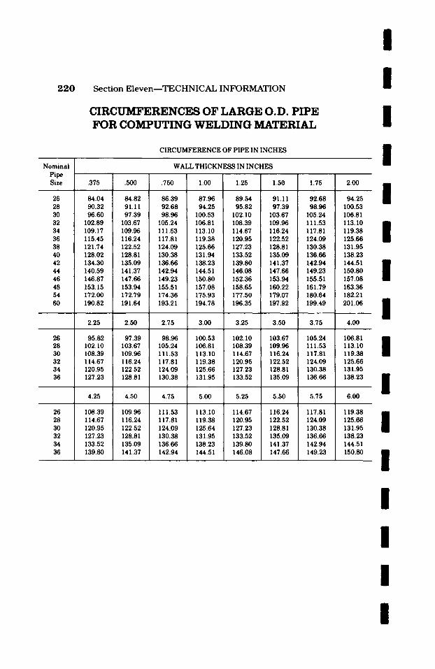
2 2 0 Section E l even - -TECHNICAL INFORMATION
CIRCITMFERENCES OF LARGE O.D. PIPE FOR COMPI.PrING WELDING MATERIAL
CIRCUMFERENCE OF PIPE IN INCHES
I I I I Nominal
Pipe Size
26 28 30 32 34 36 38 40 42 44 46 48 54 60
26 28 30 32 34 36
26 28 30 32 34 36
WALL T H I C K N ~ IN INCHES
�9 375 .500 .750 1.00 1.25 1.50 1.75 2.00
84.04 84.82 86.39 87.96 89.54 91.11 92.68 94.25 90.32 91.11 92.68 94.25 95.82 97.39 98.96 100.53 96.60 97.39 98.96 100.53 102.10 103.67 105.24 106.81
102.89 103.67 105.24 106.81 108.39 109.96 111.53 113. I0 109.17 109.96 111.53 113.10 114.67 116.24 117.81 119.38 115.45 116.24 117.81 119.38 120.95 122.52 124.09 125.66 121.74 122.52 124.09 125.66 127.23 128.81 130.38 131.95 128.02 128.81 130.38 131.94 133.52 135.09 136.66 138.23 134.30 135.09 136.66 138.23 139.80 141.37 142.94 144.51 140.59 141.37 142.94 144.51 146.08 147.66 149.23 150.80 146.87 147.66 149.23 150.80 152.36 153.94 155.51 157.08 153.15 153.94 155.51 157.08 158.65 160.22 161.79 163.36 172.00 172.79 174.36 175.93 177.50 179.07 180.64 182.21 190.82 191.64 193.21 194.78 196.35 197.92 199.49 201.06
2.25 2.50 2.75 3.00 I 3.25 3.50 3.75 4.00
95.82 97.39 98.96 100.53 102. I0 103.67 105.24 106.81 102. I0 103.67 105.24 106.81 108.39 109.96 111.53 113. I0 108.39 109.96 111.53 113.10 114.67 116.24 117.81 119.38 114.67 116.24 117.81 119.38 120.95 122.52 124.09 125.66 120.95 122.52 124.09 125.66 127.23 128.81 130.38 131.95 127.23 128.81 130.38 131.95 133.52 135.09 136.66 138.23
4.25 4.50 4.75 5.00 5.25 5.50 5.75 6.00
108.39 109.96 111.53 113.10 114.67 116.24 117.81 119.38 114.67 116.24 117.81 119.38 120.95 122.52 124.09 125.66 120.95 122.52 124.09 125.64 127.23 128.81 130.38 131.95 127.23 128.81 130.38 131.95 133.52 135.09 136.66 138.23 133.52 135.09 136.66 138.23 139.80 141.37 142.94 144.51 139.80 141.37 142.94 144.51 146.08 147.66 149.23 150.80
I I
I
I I I I
I I
I I I
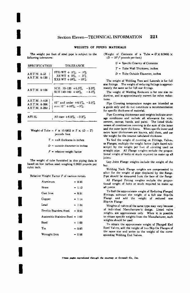
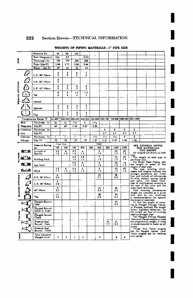
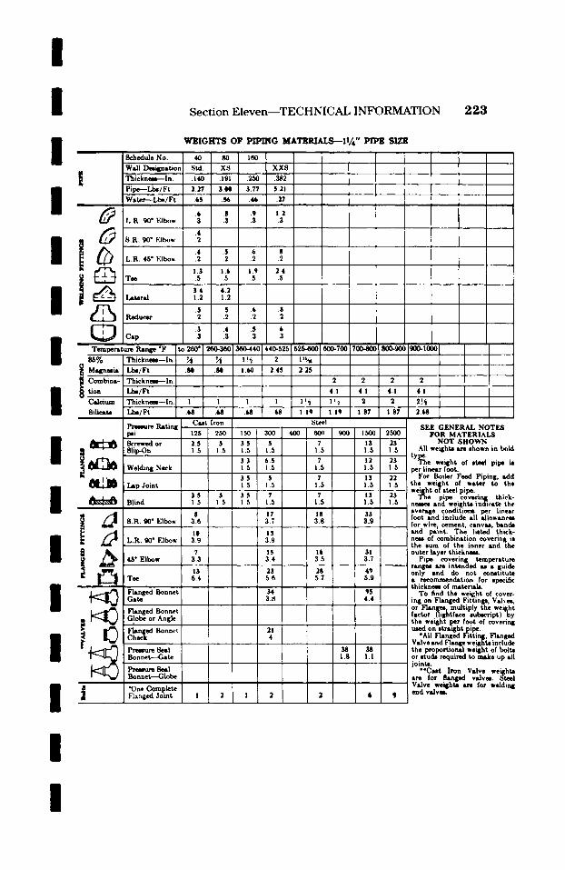
I /
S e c t i o n E l e v e n - - T E C H N I C A L I N F O R M A T I O N 2 2 3
I W E I G H T S OF P I P I N G M A T E R I A L S - - I 1 / ~ " P IPI t SIZE
�9 S c h e d u l e No. , 40 . 80 160 I 1
Wall I)mi4pmtion Sad. XS XX8 I " t ";rhicknem---In. " " .191 .2,50 .382 "
I "Pipe--Lbe/Ft " 2.~/ " 3.N 3.77 5.21 ~ " l " r . Water---Ll~/Ft .65 .~ .I~ .17 1
| | | , ~ | .6 .8 .9 1.2 i
L.R. 90" Elbow .3 .3 .3 .3
.4 I ~ 8.R. 90" Elbow .2 �9 . . - ,
"" , .s .6 S L.R. 45" Elbow .2 .2 .2 .2
1.3 1.6 i .9 2.4 Tee .5 .5 .5 .5 1
I 3.4 4.2 L,teral 1.2 1.2
.2 .2 .2 .2
.3 .4 .5 .6
I C.p t .3 .3 .3 .3 �9
8 6 % Thicknem--In. ~ ~ ! !~ 2 1 '~t I �9 . o . �9 i .
Magnesia �9 Lbs/Ft .841 .80 �9 I.~0 24S 2 . 2 5
Combine-. Thicknme--ln. . , . 2 . 2 , 2 2
I tion Lbs/Ft 4.1 4.1 4.1 4.1 CMeium . Thicknem--ln. I I I I I!4 I :'2 2 ~ 2 2~
�9 . ,
Silicate Ia:m/Ft .68 .68 .61; 68 1.19 1.15 1.87 1.87 2.68
~re Ratin~ Cut Iron Steel ~ SEE GENERAL NOTES .i m I 2~ ~5o 3oo 4oo[ ~ o o o l , ~ 2 5 o o F O R M A T Z R : A L S
1 " Welding Neck 1 5 1 5 per linear foot.
' For Boiler Feed Piping, adc i 3.5 15.5 17.5 13 ~ the weil[ht of water to th, Lap Joint i.5 we'~ht of steel pipe.
Blind 1.5 I 5 1.5 1.5 n m and weights indiea~ th, " ~ . average conditiotm per liner
8.R. 90" Elbow 308 :~7_ 18 33 foot and include all allowance ., 3.8 3 . 9 for wire. cement canvu ban& I t , . , .
1O 13 and pamt. The Imted thick I L.R. 90" Elbow 3.9 _ 3.9 nero of combination covering it
i
the sum of the inner and tl~
3.4 .. 3.7 i Pipe covering temperatun rangm i r e intended u s gui&
t3 23 28 45 only and do not cormtitub Tee 54 5.6 5.7 l 5.9 a recommendation for epecifi,
4.4 ing on Flanged Fittinlp,, Vshee Flanged Bonnet - I or Fierily.multiply the weigh'
factor (lightface subscript)b3
C F ~ e d used on ,tm~ght pipe. Bonnet ~41 *All Flanged Fitting, Flange~ I Valve and Flange weil~h~ inclu&
~" Prt~ure Seal 38 38 the proportional weight of bolt Bonnet--Gate 1.8 1.1 or stud, required to make up al
iointe. �9 *Cut Iron Valve weight
Bonnet--Globe are for flanged valvm. Stee ] Valve wei~hte ire for weldin~
�9 One Complete end valves. FL~rq~ed Joint 1 2 1 2 2 6 ~ 9
I
I
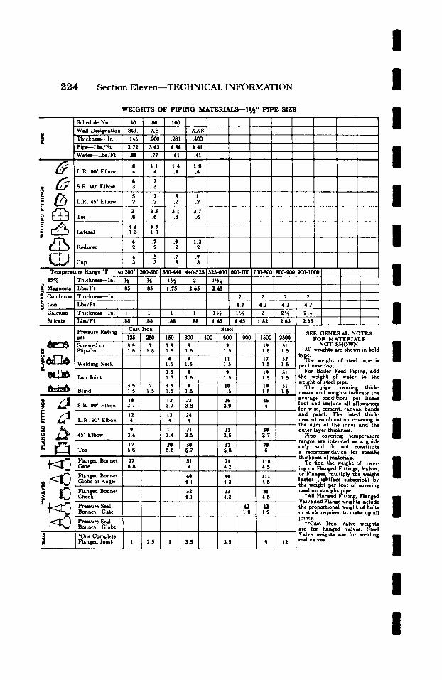
I 2 2 4 Section Eleven--TECHNICAL INFORMATION I
Schedule No. Wall Design�9
E "Thickness--ln. Pipe--Lbe/Ft W�9
L.R. 90" Elbow
, L.R. 45" Elbow
Reducer
Temperature Range *F SS%
i Magnesia
Calcium 8ilicste
Thickness---In. Lbe/Ft Thickne~--ln. Lbs/Ft Thickness--ln. Lbs/Ft
Pressure RAting psi Screwed or
i ~ SUp-On
Welding Neck
Lap Joint
Blind
~ ~ L.B. 90*Elbow
i ~ 45" Elbow
Tee
~langed Bonnet G�9
Flang~ Bonnet Globe or Ang._.____________~
Fish Bonnet
Bonnet--~ste
Pro�9 Seal Bonnet--Globe
a *One Complete Flanged Joint
W E I G H T S OF P I P I N G M A T E ~ I Z / = " P IPE SIZE
8reel SEE GENERAL NOTES FOR MATERIALS
NOT SHOWN All weights arc shown in bold
tYl~'l~e" weight of steel pipe is per linear foot.
For Boiler Feed Piping, sdd the wei~;ht of water to the weight of steel pipe.
The pipe covering thick- neeses �9 we~hts indicate the average conditmns per linesr foot and include all allowances for wire., cement, canvas, bands and psint. The listed thick- nees of combination covering is the sum of the inner and the outer layer thickness.
Pipe covering temperature ranges are intended as �9 guide only and do not constitute �9 recommendation for specific thickness of msteriab.
To find the weight of cover- ing on Flanged Fittings, Valves, or Flanges,multiply the weight fsctor (lightface subscript)by the weight per foot of covering used on stra'ght pipe.
"All Flanged Fitting, Flanged Valve and Flange weights include the proportional weight of bolts or studs required to make up all joints.
**Cast Iron Valve weights �9 re for f lanpd valves. Steel Valve weights are for welding end valves.
I I I I I I I I I
I I I I I

l
l S e c t i o n E l e v e n - - T E C H N I C A L I N F O R M A T I O N 2 2 5
I
l
W E I G H T S O F P I P I N G M A T E R I A L S - - 2 " P I P E S I Z E
Schedule No. : 40 ! 80 ~ 160
~ i i f i ~ t i , , n ; ~t2 x~ - - T-h-iel(nP~.~-- I n. " I i ~
~--~,~:~,.7~:t -~ *.6~
. . . . . . . . . . . . . i. ."; R. 90 ~ I . : l t~,w 3
. . . . . . . . . . . . 8 I , .R . 45 ~ Eib<,w 2
r l -,,+ ~ +_+._+ L i S.02__~ 7.__~
' ' + I V 1.3
I I ] l b .2 i "2
I ~7 1 s Tee fi .G 1 .6
. . . . ;6. , : ! 9~. /-- l .ateral I 4 I 14
. . . . . . . . . "7- - i +---(7-', --7~ R~,~ .... , -----L--a 1- - ' - - + .L .a
- - - ~ - + ~ ....
~ . i+_s ~.--_:. - ~ ?.03_.[_,__ .97 .77
+#
s.7 i
f l '
i __.. : ~ . . . . . ~__ 1.9 ' t '
I ~ ', i .---77-1 + i ,.+ 1 '.~ I ; I -
~ , + " " ~ L + . i ' L ~ . , 1_ i i �9 ,.,,.,, ..... ~ ..... , , + , ~. l.. ~ . ~ ~ . ~ l ~ . + . o +++~.~ .+~>+o +~oo 1~o+~ 1 ~ ~ I ~ , ~
M,~n,~ia L-~,.,:~ . i - + - - ~ - + ~ - F ~ g - + ,s + ++ ' i ' , )n ,b ina . Thick . . . . . In ; r i I t 2*, 23.,
n +.oo + ~ , m - .... t + , t : , , , , t ' a lc ium "l 'hivkne~- - I n I ! 1 1 | ! l ~ 1 L2 2 2
' ~-rcwed or
~ . - ~ t ,,,.,,,rag Xe,-k
IJC-,.L2"_LI+ , I l l i n d
'~ ~ S R .qo ~ EIh,)w ~ " .
/ [ !
l ' r e~ tz re RatmK ( 'a.~t l r , ,n .~._ pat 125 250 1 1,50 ,34)0 , __
S l i p - ( ) n 1.5 1.5 I !
6 I0 i 5 ! . 5 _
6 5 , 0
, 65 I 0 4 8 I tO n 1 1.5 15 I ! . 5
' i I 16 I 24 l q 29 i 3R 1 3 8 3 S 3 8 ,,
18 l 27 22 L.R. 90 ~ Ellmw . -1 1 I 4 ! 4 I . . . . . . . . . . . . . . .
14 22 16 24 45 ~ F l b o w 3 4 . . . . . . . 3 5 3 .t 3 5 [
23 ~7 #7 ; 4 1 Tee 5.7 . , T , , , , ,
l i
(;ate. 6 9 ~ 7 3.9 I, Fl,,,,,~,...~ ...... ,. 3o - - + ~ .2 i s i = ( ; lobe or Angle 7 : 7.3 4 : 4 3
r [ ? ' : + ' + i Premmure ,~'al I ' , I +, . . . . . . t - - G a t e 4 . . . . . . . . . . . ' I
. . . . . ,+ . . . . . P r ~ u r e .'~eai I i ~- Bonvwt - ( ; l o b e / , I I
I
I +s +
I +
St~.l
4OO 600
II 15
13 15
~ ! _ _ I1 1 1.5 '
i 35 ~ 4 i
,L~LI__
i Z 83 4 , 4
| 78 " 4.4
4.4
. . . . . T _
9OO
, 4-,- 3L'+ ~ 3~'k 7T-[ -4.] 2 ~ z [ 2t.'2 3a, i ~a+
~ (5)vt t i , lc t~ I ' Flattged Ju ln t J 1.$ 3.5 " 1.5 4
L .___L 4 . 5
. [. ,
- - - i ,
I,NI0 2,NI0
32 48 1 5 i 5 _.. 2q 48 1 5 1.5
-32 4~ 1.5 1 5
31 4 9 ! .5 1 .5
4 . 2 .... t
L I .j
'+ I 3.9 .
129 I 6.3 =
154
157 l 4R . . . . . . . . 106 [ 4 8 . . . . ~ _ _ _ _ _ 75 I 1.4
. . . . . 135
, 2 .1 .
SEE G E N E R A L N O T E S FOR M A T E R I A L S
N O T S H O W N All weights are shown in bold
tYtl%~e"~ weight of steel pipe i4 per l inear foot.
For Boiler Feed Piping, add the weight of water to the wenRht of s tal l pipe.
The p t |~ covering thick. ne.~mm+ and weight~ indieat+ th, average com|itiovm per lineal foot anti include all aliowaneel for wire, cement , canvas, ban& and pamt. The listed thick, n,.~.~ of combinat ion covering h tht. sum of the inner and thq outer layer thu kn~s .
Pipe covering tcmperatur l rangt.~ are in tended t m � 9 guidq only and do not cormtitut4 a r ecommenda t ion for specific thickne.+ of material&
To find the wetght of cover, ink on Flanged Fittings. %'aires or Flange. , mult iply the weight factor (i tghtfaee submeript) by the weight per foot of covering u.+ed on s t ra ight pilm.
"All Flanged Fttt ing, Flanged Valve anti Flange wetl~hts include the prolx>rtionai weight of boifa or s tuds required to make up all joints.
"~ Iron Valve w e i g h ~ are for flanged valve, . Steel
"~ ', Valve weighta axe for welding end v~lvee. 12.5 ] 21
l /

2 2 6 S e c t i o n E l e v e n - - T E C H N I C A L I N F O R M A T I O N
S~-hedule No. Wall D~ignation
~, Thicknc~--ln. Pipe--Lbe/Ft Water - [,ha, Ft
I , R 90" Elbow
~ .~R. 90" Elbow
i L.R. 45" Elbow 6)
i ~ Lateral
Reducer
Cap ~ . _ . . _ . . . . . _ ~ Temperature Range ~
85% Thickness--In. ~: Magnesia I,bs, Ft
i Combin---------~ tion l,bs / Ft Calcium [ Thickness--In. Silicate Lbs/Ft
Pressure Rating psi ~rewed or
a Slip-On
l ~ Welding Neck
~ . ~ l,ap Joint
~ [ Blind
I ~ [ S.R. 90" Elbow
L R. 90" Elbow
O 45" Elbow
WEIGHTS OF PIPING MATERIALS-2t/2" PIPE SIZE
I I
/ I
J I ] n
('ast Iron
~ ' Flanged Bonnet !Gate
Flanged Bonnet Globe or Angle
Flanged Bonnet Che,-k Prmaure Seal Bonnet--~,ate
Pressure ,~k,a I Bonnet -(;',',t~ "One Complete ' " Flanged Joint ~ ~
Steel
' I i l
I I /
SEE GENERAL NOTES FOR MATERIALS
NOT SHOWN / All weights are shown in bold
tYli~he" weight of steel pipe is per linear foot.
For Boiler Feed Piping, add the weight of water to the weight of steel pipe. n
The pipe covering thick- / nesses and weights indicate the average conditions per linear foot and include all allowances for wire, cement, canvas, bandl and paint. The listed thick- ne~s of combination covering is the sum of the inner and th,~ / outer layer thickness.
Pipe covering temperature ranges are intended as a guide o,dv and do not constntute [ ~ recommendation for specific
, thickness of materials. i
To find the weight of cover- ing on Flanged Fittings, Valves, / or Flanges, multiply the weight factor (lightface subscript) by the weq~ht per foot of covering used on straight pipe.
~ Flanged Fitting, Flanged Valve and Flange weights include the proportional weight of bolts
I or studs required to make up all joints.
"'Cast Iron Valve weights are for flanged valves. Steel Valve weights Jure for weldinf
I end vtlveL / / /
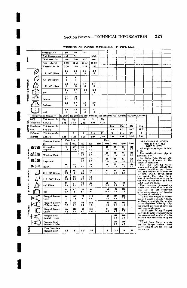
/
I Section Eleven--TECHNICAL INFORMATION 2 2 7
I I / /
I I /
I / / / /
8e.hedule No. " ~ 1 Deaignation Thic.kness--ln.
E l~pe--Lbe/Ft Wa~r- - l ,be , 'F t
L.R. 90 ~ F'lbow
I..R. 45 ~ Elbow
~ ~ T ~
d~i , Cap
Temperature Range *F 85% Thi,'kness--ln.
z ~ Magnesia l.bs/Ft
i ~ Thi,.kneaa--ln. t i o n l,bst l"t
Calcium t Thiekne~--In. Silicate Lbs/Ft
Pressure Rating psi
~ No'reded or ,~lip-()n
z~ r ~ Welding Neck
~ - ~ l ~p Joint
Blind
i ~ 45 ~ Elbow
"Fee F
F'langed Bonnet Gate
Flanged Bonnet Globe or Angle
Flanged Bon=,et Cheek
�9 ~ Pressure .Seal Bonnet--(;ate
~ Pressure ,~,eal Bonnet- -(;lobe
�9 ~ *One Complete Flanged Joint
W E I G H T S OF P I P I N G M A T E R I A L S - - 3 " P I P E SIZE
xx~ ~__ ~ . . . . . . . . . . i ~ ' ~ ~ -T~I ] i 1 , ,.5~- --~___~ _~_I : - - ' ,
('ast lrolf
1.5
15 I 6 _._
15
1.5
Steel SEE GENERAL NOTES
FOR MATERIALS NOT SIIOWN
All weights art shown in bold
tYllYhe-- weight of steel pii~ iJ per li,ear foot.
For Ik.ler Feed Piping, add the weight of water to the weight of steel pipe.
The pipe covering thick- nesses and weights indicate the average ,.onditlons per linear foot and include all allowan~'es for vdre. ,.eme,t. ,.anvu, banda :l,d paint. The listed thick- , e~ of ,.ombi,ation covering i. the sum of the inner and the outer layer thickness.
Pipe ,-overing temperature ranges are intended M a guide o111~' and do ~lot constitute a be~..,,mendation for specific thickness of materials.
To find the weight of cover- ing on Flanged Fittings, Valves, or Flanges. multiply the weight factor (lightface sube~.ript) b y the weight per foot of covering uaed on straight pipe.
*All Flanged Fitting, Fhnged Valve and Flange weights include the proportional weight of h~lts or studs required to make up all joiwt.s.
**('ut Iron Valve weights are for flanged valves. Steel Valve weights arc for ,eldlng elad valves.
/
I
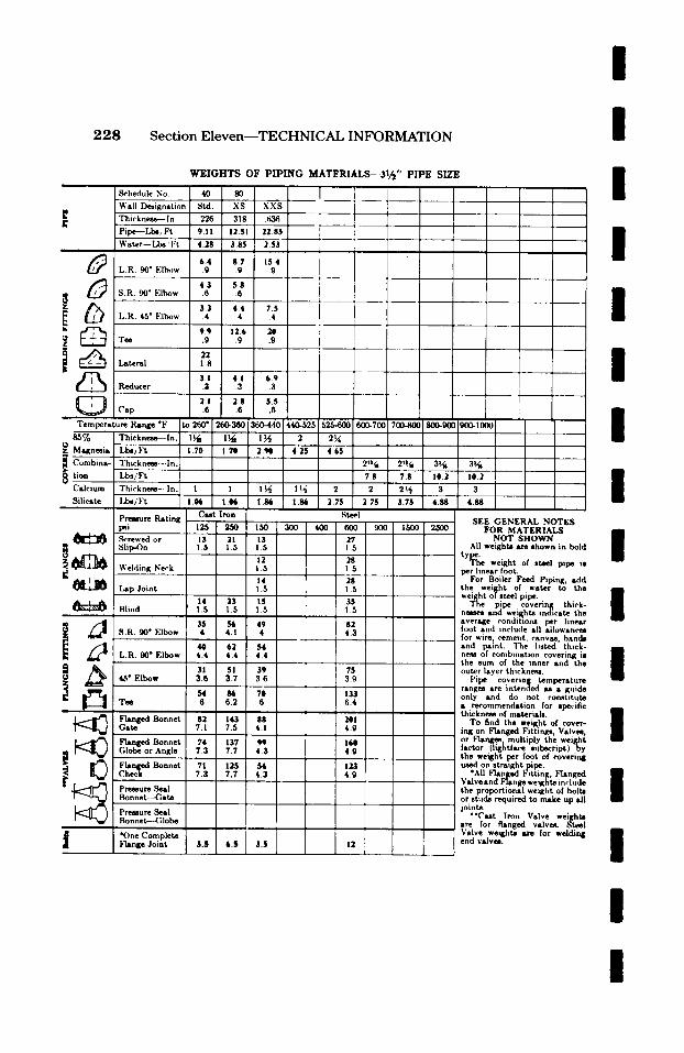
I 2 2 8 S e c t i o n E l e v e n - - T E C H N I C A L I N F O R M A T I O N I
W E I G H T S O F P I P I N G M A T E R I A L S - . 3 1 / 2 " P I P E SIZE
Schedule No. 40
Wall Designation ' Std.
r T h i c k n e ~ I n " I .226 i,
Pipe---Lbe, Ft 9.11
r Water - -Ll~ 'F t w 4 2 8 i,
~ 6.4 L.R. 90 ~ EIb~)w .9
r �9 ! 4.3
S.R. 90* Flbow .6 ~ , ,
~ , 3.3 i L.R. 45" Elbow .4
r t
Tee
Lateral !
Wf~l ' Reducer r !
Cap
Temperature R ~ g e "F to 260"
85% " Thickness--In. 1~ '
Magnesi~ ' Lbel Ft 1.70 ~ Combint- ' Thickness---In.
i tion ' Lbs/Ft ! ! Calcium Thickness-. In.
Silicate LI~/Ft
9.9 .9
Pressure Rating psi ~rewed or
f
~ . ~ Lap Joint
22 1.8
I i XS XXS , i .318 .636
I i 12.51 22.85 1
3.85 2 5 3 i
8.7 15.4 [ .9 .9
t 5.8 i �9 ~ ,
4.4 7.5 i
A
.4 .4 I
1 2 6 20 .9 .9 i
3.1 4.1 6 . 9 .3 .3 .3
268 5.5 �9 .~
, 1 ~ . , l ~ j 2 � 8 8 .
1.71D 2.90 4.25 4 . 6 5
1 I
I .o4~ I .N,
C u t Iron
125 25O p i
13 21 1.5 1.5
14 23 IS ' Blind ' 1.5 1.5 1.5 ! l ! .l
, ~ 35 56 49 S.R. 90" Elbow 4 4.1 4
40 62 54 L . R . 90 ~ Elbow 4.4 4.4 4.4
,, , . .
, ~ 31 51 39 45" Flbow 3.6 3.7 3.6
f i i l
Tee 6 6.2
GaFl~ed Bonnet 82 143 88 7.1 7.5 4.1
! Flanged Bonnet ' 74 I 137 ' 99 Globe or Angle ' 7.3 7.7 4.3
' Bonnet I 71 ' 1 2 5 ' 54 CL~hhe~n~ged 7.3 7.7 4.3
~i ' Pre~ure Sr Bonnet--Gate ,
Pressure Seal Bonnetf.--Globe
FlAnge Joint 3.5 6.5 3.5
2'*~, 21s~ I 3 4 |
7.8 ! 7.8 10.2
, .~ t .~ 27s 27s 3 . 7 s . 88 Steel
150 3OO 40O 6OO 9OO 1 5 0 0 250O 13 27 ! .5 1 .,5
12 28 i .5 1.5
14 28 1.5 1.5 i i
35 1.5
82 4 .3
75 3.9
133 6.4
4.9
160 4 .9
123 4 .9
3 4 10 .2 Z ; ; - -
t t i 23
4 . 8 8 [ 1 ,
SEE GENERAL NOTES FOR MATERIALS
NOT SHOWN All weights are shown in bok
tY~?l~e"~ weight of steel pipe ia per linear foot.
For Boiler Feed Piping, �9 the weilsht of water to th, weight o/steel pipe.
The pipe covering thick. nemes and weights indicate th, average conditions per line~ loot and include all allowance, for wire. cement canvas, ban& c and paint. The listed thick heSS of combination covering il the sum of the inner and th, outer layer thickness.
Pipe covering temperaturl ranges �9 intended as �9 guid, only amd do not constitut4 �9 recommendation for specific thickness of materials.
To find the weight of eove~ lng on Flanged Fittings, Valves or Flanges, multiply the weighl factor (lightface subscript) by the weight per foot of coverin I used on stratght pipe.
"All Flanged ~ itting, ~lange~ Valve and Flange weights in,.luth the proportional weight of boltl or studs required to make up all joints.
" ' C u t Iron Valve we~ht~ are for flanged valve~ Steel Valve weights ~rv for we]di~ end valveL
/
I /
I I I /
I /
I I I / /
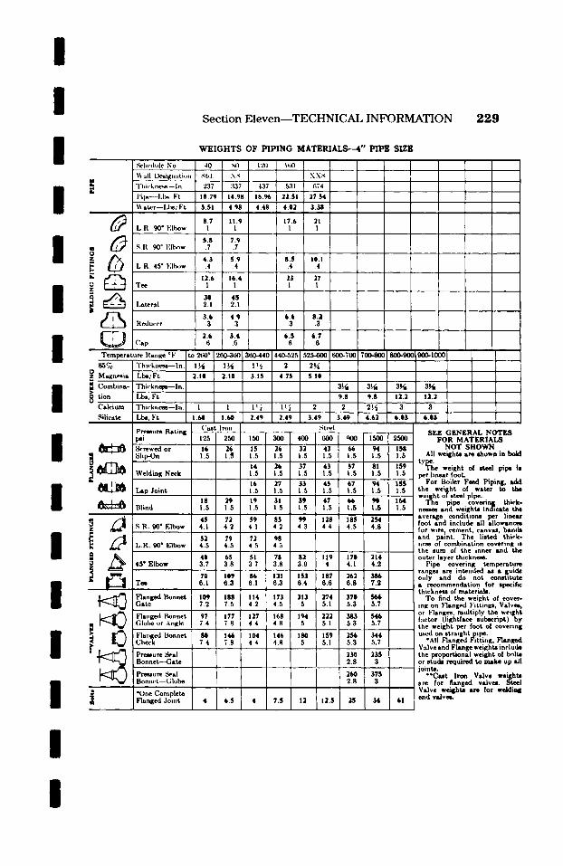
I / /
I /
I /
I / / /
I /
I /
.'~-h~lulc No. Wall lk~ignatio.
I~ "l'hi,-kne~ --In. E
l'il~.~- i.t~ Ft ~Yater--l~s/Ft
L.R. 90" Elbow
m / ~ S.It. go ~ I.:ll~w O
L.R. 45 ~ Elbow
" D
i Ii~ Lateral Rea.,'er Cap ~ _ _ . . . . . . . . _ ~
Temperature lla,ge ~ 85% i "l'hwk,.rs~-In.
z O Magn~is ' l . l~/Ft Combina- i Thi,'knem~--ln.
i Lbs' Ft Calcium Thi('k,,c~--I.. Silicate : LI~/Ft
i Pressure i~ting psi
~ I~rewed or Slip-On
~ l ~ I Lap Joint
~ Blind
L.R. 90 ~ Elbow
~ _ ~ 4 5 " Elbow
Tee
~ ] ~ Flanged Bonnet Gate
Fla.ged I~onnet Giulm or Angle Fta.ged Bonnet
I Check Pressure Seal Bonnet--Gate
Pressure ~ I Bon,,.t--Globe
~I *One Complete ][ Flanged Joint
Section Eleven--TECHNICAL INFORMATION 2 2 9
W E I G H T S OF P I P I N G M A T E R I A L S - - 4 " P I P E SIZE
( ' ~ t In)n I ,~t~l Sgl~- GENERAL NOTE3
FOR MATERIALS NOT SHOWN
All weights ,we shown in bold
tY~l~e" weight of steel pipe hs per linear foot~
For Boiler Feed Piping, add the weil~ht of water to the weight of steel pipe.
The pipe covering thick- nesses sad weights indicate the ~ verage conditions per linear oot and include all allowances
for wire t cement, canvM, bsmht and paint. The listed thick- ne~m of combination covering is the sum of the inner sad the outer layer thickness.
Pipe covering temperature ranges are intended M �9 guide only and do not constitute �9 recommendation for specifi�9 thickness of material&
To find the weight of covel,- ink on Flanged Fittinl~, Valves, or F3anges, multiply the weight factor (lightface subscript) by the weight per foot of covering u~d on struightpipe.
*All Flanged Fitting, Flange[ Valve and Flange weights includs the proportional weight of bolts or studs required to make up all joints.
" 'Cast Iron Valve weights are for flanged vslveL Steel Valve weights are for welding end vsiveL.
/

2 3 0 Section E leven- -TECHNICAL INFORMATION
No.
WEIGHTS OF P IP ING MATERIALS- -5" PIPE SIZE
Wall Designation XS J ~ . . �9 I 2.r~q I 37L I .r~l~l I 625 I 7.r~3 I I
Pipe-- l,bsJ Ft ~ - O 4 32.-% 381"55 8bb 789 709 b35 S b2 V'-~ Water--l,bs. Ft
G J I,.R. 90" Elbow
L.R. 45" Elbow
f t ~ t e ~
~ Reducer
Cap
Temperature .~ange ~ Thicknesa---ln. Lbs/Ft Thieknem~-ln. Lbs/Ft Thieknem--ln. Lbe/Ft
~ %
tion 8 ~
8ilicate
Premure Rating "~"
Screwed or
~ ~ ~ t Blind ~ 8.R. 90" Elbow
L.R. 90" Elbow
•'••I ~mged Bonnet Gate
Flanged Bonnet .Gl~ o= Angle I
~'langed Bonnet I Che~.k
P~ure Seal Bonnet. -Gate
i P~mure ,'~al ~ . Bonnet - ( ; I ~
B *One Complete 1 Flanged Joint
Steel
23q 4.3
SEE GENERAL NOTES FOR MAXERIALS
NOT SHOW~i All weights are shown in bold
tY~'~l~e" weight of steel pipe is per linear foot.
For Boiler Feed Piping, add the weil$ht of water to the weight ol steel pipe.
The pipe covering thick- nmees and weights indicate the average conditions per linear foot and include all allowancm for wire t cement, canvas, bands and paint. The listed thick- ne~ of combination covering is the sum of the inner and the outer layer thickness.
Pipe covering temperature ranges are intended as a {uide only and do not constitute a recommendation for specific thicknms of materials.
To find the weight of cover- ing on Flanged Fittings, Valves, or Flanges, multiply the weight factor(lightface subscript) by the weight per foot of covering used on straight pipe.
*All Flanged Fitting, Flanged Valve and Flange weights include the proportional weight of bolts or studs required to make up all joints.
**Cast Iron Valve we~hts are for flanged valves. Steel Valve weights am for welding end valves.
I / I I / I I / I / I / / / / /
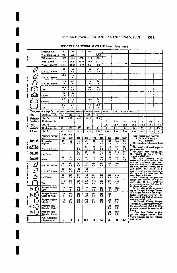
I I I I I I I I I I I I I I I
Schedule No. l~ignation
E Thicknem--In. Pipe--Lbs/Ft Water--Lbs/Ft
L.R. to" Elbow
I ~ S.R. to* Elbow
L.R. 45" Elbow
Reducer
Cap
Tcznper�9 Range ~ 8S%
I Ma4lnmia
� 9 Calcium Silicate
Thickness--ln. Lbs/Ft Thickness---In Lbs/Ft Thickness--In Lbs/Ft
Premure Rating
~rewed or
i ~ Welding Neck
~ - ~ Lap Joint
Blind
~ S.R. to" Elbow
i L.R. to" Elbow
t~ 45* Elbow
w ,w
F]anged Bonnet Globe or Angle
~ P r ~ m Seal Bonnet---Gate
Bonn~---GI~
Flanged Jo~mt
Section Eleven--TECHNICAL INFORMATION 231
WEIGHTS OF PIPING MATERIALS---6" PIPE SIZE
Steel S E E G E N E R A L N O T E S
F O R MATERIALS NOT SHOWN
All weights are shown in bold
tY~?l~e" weight of steel pipe is per linear foot.
For Boiler Feed Piping, add the weight of water to the weight of steel pipe.
The pipe covering thick- nesses and weights indicate the average conditions per line~ foot and include all allowances for wire. cement, canvas, bands and I~nt. The listed thick- hess of combination covering is the sum of the inner and the outer layer thickness.
Pipe covering temperttum ranges are intended u �9 !~ide only and do not const,tute �9 recommendation for specific thickness of material�9
To find the weight of eove~- in~ on Flanged Fittinp, Valves, or F1~q~, multiply the weight factor (light/see 0ubscript)by the .weight per foot of covering used on stra~ht pipe.
�9 All FIant~ Fitting, F1ant~ Valve and Flange weights include the proportional weight of bolts or studs required to make up all joints.
�9 "Cut Iron Valve weishts for f l az~ valves. 8�9
Valve weights are for weldi~ end valveL
/
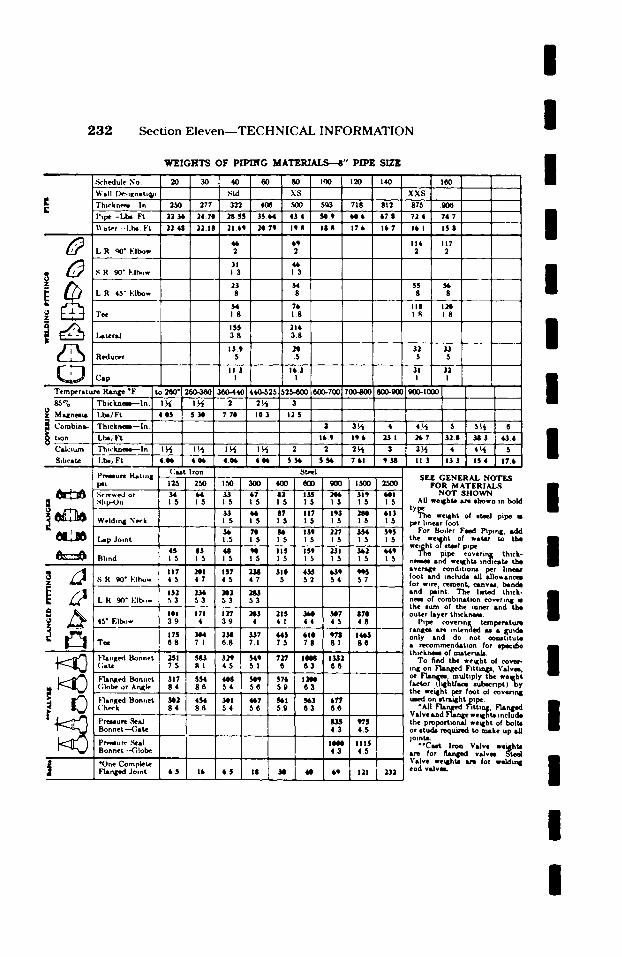
2 3 2 Sect ion E l e v e n - - T E C H N I C A L INFORMATION
:~chedule No. Wall 13m-~Kn�9
I~' Thlcknem , in [ l',pe. - LJ:~ Ft ~at~r,,-!.1~, Ft
L R qO" Elbow
L R. 45" Elbow
O ~ - ~ Tee z w
_ Reducer
C�9 Tern p e r � 9 R~n~ "F 8~%
O Z M .4tnesul
Combini.-
tion
C,dclum
Stl~cstr
Th ickn~- - - I n.
Lbe/Ft
T h l c k n ~ i ~ l n
Lbs/Ft T h w ~ I n
I.I~/Ft
t)re~ur~ last ,n | psi Screwed or
:1 s l , ~ .
~ ~ Weld,rq~ Neck
L~p Joint
Bhnd
45" Elbow
Tee
F'lanKed Bonnet (;at~
Fl i r t ed Bonnet (;lobe or An~le
F'lanKed Bonnet ('heck r ~ ~'n~ure ~
, Bonnet--G�9
Pr~sure .~al Bonnet--C.lobe
*One C~m plete Z F'~ n { ~ Joint
W E I G H T S O F P f P [ N G M A T E R Z ~ " P[]PE SIZE
(?,.it Iron I ~t4~i SEE GENERAL NOTES
FOR M ATERIAL.~ NOT $11OWN
All we~ht, ,u l 8bown in bold
tYi~" weq~ht of etmel pipe iB per hnear foot
For Boiler Feed Piping, add the weq~ht of water to the wei_~ht of steel p,pe
The pipe covenrq[ thick- ne~a and weq~ht~ indic�9 the a v e r ~ eond,t|on8 per llne .u, foot and include all 1allow�9 for wlr% cement, canvu, b inds and psint. The l i~c l thick- ne~ of comblmstton coverlr~ iB the ram of the loner and tbo outer layer thickrmm
Pipe r g tcmperatu~ ranlEm Lrl intended u �9 {~ulde only and do not eo~tituto �9 reeomnnsendAtion for ep~iJ~ thlckne~ of tmsterU~.
To find the weq~ht of r Inl on Ftsn(~d Fittmlp,. Vidvm. or F~nceo.mudtlply the weqlbt f,~'tor (lqKht/~ce eubecnpt)by the wei1[ht ~ foot of coverm~ used on otrlu~htpipe.
"AJI Franked F, ttin&, F ' m ~ V�9 Lnd F~n&e weqihto include the proportborud weq[bt of bolt= or etud, m q u u ~ to make up &il jolntIL
" ' C u t Iron V,dve we~hto tu~ for tlsmll~l valvm. St~l Valve weq~ht= m for weklU~ end wdv~.
I I I I I I I I I I I I I I I I

/ /
I Section Eleven--TECHNICAL INFORMATION
W E I G H T S OF PIPING MATERIALS-- I0" PIPE SIZE
,%'|w(h,h' N,, 20 I :~, ,,, ' ,~ -I--- . . . . i
2 3 3
! t
r.
# /
Wall lk---mnat ,,.,
"l 'hi, 'ktH .'s- In lhlw l . l , s l"t ~ :tt, 'r - l . h - - I t
I , .R. 90 ~ El l~,w
2."X) :~7 2S " ~ 34 24 35 77 34 9~
i
3oi5 ,~0
40 5 54.7
.~2 3 L .~4 1
' 5 2 5
.~ R. 90 ~ l.:It~,~ .... ! . . . . .,
. ~ ~o I . .R . 15 ~ F:I I , ,~ ]. . . . . . . . , ~____
"I'~ ; 2 1
I l ,a te ra l ', ' I 4 4
R,,dueer ~ .___~_6
? 7 ~ 2.1
4.4
.6
I l ' ~ I ~ m ' ~ ' ~ o ' l c n q w r a t u r e f lange ~
;J .Magnesia Z
I i ( ;o,nbina- tion
( ' a l , 1urn S i l i ra te
"rhi,.kn~ ..x~ - lu. i l ,hs, F t " l ' h i , ' kne~ I,, l .b~, Ft i
l"hieknc-.q l,,.l
1.1~-~ F't
l 're-.~,,re Rating l),, I
~li l~-()n
~ ,I.',.|. I illll~ .~ c,.k
I ~ l.~tl, .h,1,1t
Bhnd
�9 ~. I( ~.~0 ~ l-:lh,,w z
~. I , .R. 90 ~ F'll~m-
~Z 45 ~ F'IN~w
Flanged Bonne t . ( , a t e
~ I"lm qled Bonnet (;lobe or Angle
Pre~ure Seal Bonnet -Ga te
l'rt.~qure Seal Bonnet - - - ( ;lobe
i 01 )he ( 'omplcte Flanged Joint
__1__ ] 260 ~ 2q~O-,~kq .
5.20 6.60
$ I0 5 1 0
125 2.50 ~
5 3 97 1 . 5 ! .5
71 136 1 . 5 1 . 5
190 3 2 3 4 . 8 4 . 9
24s a s s I ~ o I 43s
160 273 I t85 I 2S8 4.1 4.2
7.2 7.4
471 899 I st3 I as s 7.7 8.3 I 4 . 7 1 5.3
9.1 9.1
453 I 751 I 413 I 5sb
I S 33 1 I S I 38
I
t ; [ , .
:')l.El . - l ~ [ ~ | : ~ ' I (X)0"- I ., l l~:, i 64 .t 76 9 8q 2 104 I I I I.~ 7
3,1 " "" 2q 5 2~, 0 -26 I / 24 6 " �9 I
: i 22b : : ' " :: '2" I , .; . . . . . ~ . . . . . . . . . . . . . . . ~ _ _ ..
I
' I . . . . . . . ': I 109 "
222 , i
- - - . . . - . . . . . . . . . . . ~ . - 1 . . . . . ' - - 1 I
'~ . . . . ~ - i - - - - - ~
I I '
- - - - - - - - - - - 4 - - i . . . . ~ . '~ ~ ~4 t !
- - r
3 3 ~ 4s,f, - .
2 3 . 5 28 0
~ s.76 lo .s
.~t,.,.I
1.5 1 5
447 1129 15 I 5
589 1131 I,~ 15
I.,5
.5 fi I 5 ~, ,
332 I 572 I 732
578 I 10eT[ 1 4 ~ 7 8 I ~.4 I 8.7
I 25861 7.1
1800 I 1910 4 . 9 1 5.2
52 I 72 I 95 I 184 L 4 4 5
I _ i
i ._.-
i i I
6
SEE GENERAL NOTES FOR M A T E R I A L S
NOT S H O W N ALl weights are shown in bold
tY~l~e" weight of steel pipe is per ! inear foot.
For Boiler Feed Piping, add the wei!~ht of water to the weight of steel pipe.
The pipe covering thick- neeees and weights indicate the average condiUons per linear foot and include all aliowanem for wire z cement, canvas, bands and paint. The listed thick- nese of combination covering is the sum of the inner and the outer layer thickness.
Pipe covering tempera ture ranges are intended as s guide only and do not constitute a recommendation for specific thickneee of materials.
To find the weight of cover- ing on Flanged F i t t i n p , Valves, or Flanges, mult iply the weight factor ( l i g h t f ~ s u b e c r i p t ) b y the weight ~ foot of covering used on stratght pipe.
�9 All Flanged Fitting, Flanged Valve and Flange weights include the proportional weight of bolts or. studs required to make up all joints.
" 'Cas t Iron Valve weights are for flanged valves. S t ~ l Valve weights are for welding end valves.
I
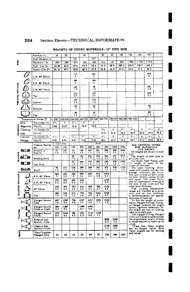
/
2 3 4 Section E leven- -TECHNICAL INFORMATION I
W E I G H T S O F P I P I N G M A T E R I A L S - - 1 2 " P I P E S IZE
Sch~lule No. 20 30 Wall Designati-n Thieknex~ In .~50 330 Pipe- l .bs/Ft 33.38 43.8 Water- - l .bs /Ft 51 I0 49.7
L.R. 90* Elbow
/ ~ S.R. 90* Elbow
! L.R. 45* Elbow
Tee ..
Lateral
/ L - ~ Reducer
I J Temperature Range *F t 1:
~ ~ o - - - ~ - - ~ "l'h ic k ncsg--I n ." Magnesia [ l.b~/l"t
az ~ Combina- " l ' h i , . kne~ ln .
tion - i~s , l"t Calcium Thwkv~ess--lw. '
Silicate -L-~/Ft I
Presaure lLatsng psi Screwed or .qlip-()n
~ ~ Welding Neck
Lap Joint
Blind
~z ~ i S 'R 900 Flbow
~ L.R. 90*FIbow
0 45* Elbow
Flanged Bonnet Gate
Flanged Bonnet Globe or Angle
Flanged Bonnet Check
Prtaaure Seal Bonnet.-(,ate
119 3 _~ _
80 2
Preasure Seal Bonnet--Globe
tOne Complete Flanged Joint
8
1
13
112
104 2 4 78
536 I 5.4
i 375 , i
I 181 I 1.3 ! 3 6 0 1
i i
/ / /
I 1.5
L ! L__
i 3'J~ ' 4
_ _ , ,
Cast Iron I Steel ! 25 250 150 300 400 600 900 71 137 ~'25 114 ~ 163 261 388 1.5 1.5 . 1.5 1.5 1.5
~9 .5
17 .5
96 177 18 1.5 1.5 .5
265 453 45 5 52 5
375 553 ,85 6.2 6.2 ~.2
235 383 ~82 4.3 4.3 ~.3
403 684 ;I $ 1361 7.5 7.8 '.5 8 7
687 1298 t26 33', 161 2'283 /
7.8 8 5 1.8 7.1
8418 1200 40 q 1491 9.4 9 5 5.5 6.8
674 1160 rot ;74 II1: 1168 9.4 9.5 ~.5 5.5 6.8 7.1
42 181 233 361 .5 1.5 1.5 1.5
69 193 293 445. 5 1.5 1.5 1.5
~9 260 341 475 5 ! 5 i .5 1.5
~ 9 669 815 1474 ~.2 b 5 5.8 6.2 ~24 1598 ~2 6.2
t 14 469 70.5 I 124 |3 4 5 4.7 4.8
iS4 94.t 1928 r.8 8.3 9.3
324~ 5 6.8 7.8
5.5
21541 5.5
15 44 15 ,19 69 91 124
1500 82O 1.5
691 15
92O 1.5
928 1.5
/ /
SEE GENERAl. NOTES 2.500 FOR MATERIALS /
NOT SllOWN
I Ii~.~.~nn All weights are shown in bold tv .
1671 "~he weight of steel pipe is per linear ft~)t.
For Boiler Piping, 115~ I Feed add the weight of water to the
I - - " ~e,ght of steel pipe. / The pipe covering thick- n ~ e s and weights ,ndi,.ate the average comhtions per I~v,car Joot and include all alh,~vances for w:re, cement, canva.s, bands and paint. The l:st~l t h . k - nesa of combination covering Is / the sum of the tnner and the outer layer thickne~.
Ptpe covering temperature raages are intended as a guide only and do not constitute a recommendation for specific thicknem of materials.
I To find the weight of cover- ing on Flanged Fittings, Valves, or I-%ngea multiply the weight factor. (lightface subacr ip t )by
2400 5.9
366 622
the weight per foot of covering used on stra~htpipe.
"All Flanged Fitting, Flanged Valve and Flange weights include / the proportional weight of bolts or studs required to make up all joints.
"*Cant Iron Valve weights am for flanged valves. Steel Valve weighta are for welchng end valve=. |
/ /
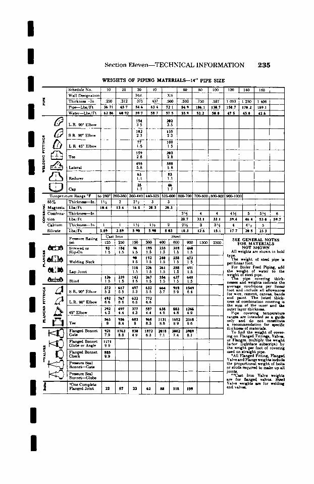
I /
Section Eleven--TECHNICAL INFORMATION 2 3 5
Schedule No. ! Wall Designation
' Thicknesa--ln.
Water - -Lbs /Ft
L.R. 90 ~ Elbow
,O' . 8 .R . 90" Elbow
~ _ Reducer
W E I G H T S O F P I P I N G M A T E R I A L S - - 1 4 " P I P E S I Z E
I0 1 20 30 40 60 , SO l l00 120 Std. X:5 [
.250 .312 .375 437 .500 .593 .750 .937 1.093
36.71 45.7 S4.6 63.4 72.1 84.9 106.1 130.7 150.7 �9 �9 �9
62.06 60.92 59.7 58.7 57.5 55.9 53.2 50.0 47.5
IS4 202 3.5 3.5
102 135 2.3 2.3
77 I00 1.5 1.5
159 203 2.8 2.8
495 588 5.8 5.8
63 83 1 . 1 1 . 1
140 160 F
1 250 I 1.406
170.2 i 189.1
4 5 . 0 4 2 . 6
35 46 Cap ! .7 1.7
8,5% Thickness---In. ! ~ 2 2~ 3 3
~z Magnesia ' Lbe/Ft 10.4 13.4 " 16.8 20.3" 20.3 " "
~ C ombina- " Thickness--In. " [ 3!,~ 4 4 4~ 5 " 5!~ 6
I . . . .
tion I,b~/Ft 28.7 33.1 33.1 39.4 46.4 53.0 59.7
Calcium Thickness--ln. I I I I/~ I ~2 2 2~ 3 3!~ 4 4 !.~ 5 , , , o Silicate Lbe/Ft 3.89 3.89 5.90 5.~ 8.03 10.3 12.6 15.1 17.7 20.5 233 . . . .
Pressure Ratin~ Cast Iron Steel psi " 125 250 150 300 400 600 9(}0 1500 2500 SEE GENERAL NOTES FOR MATERIALS Screwed or 95 184 % 195 235 318 46@ NOT SHOWN
i' i ' ' -- - - Welding Neck 1.5 1.5 1.5 1.5 1.5 per linear foot.
' ' ' 116 226 261 358 491 For Boiler Feed Piping, add I Lap Joint 1.5 !.5 1.5 1.5 1.5 the weight of water to the
. . . . weight o! steel pipe. 126 239 142 267 354 437 648 The pipe covering thick.
Blind 1.5 1.5 1.5 1.5 1.5 ! .5 1.5 nemes and weights indicate the , | s s _ i 372 617 497 632 664 918 1549 average condttions per lineau
S.R. 90 ~ Elbow 5.3 5.5 5.3 5.5 5.7 5.9 6.4 foot and include all allowanc~ . . . . i for wire r cement, canvas, bsnda
and l:mmt. The listed thick- 11 2 . . . 7 7
L.R. 90" Elbow 6.6 6.6 6.6 6.6 ness of combination covering i8
! ' ' 883 142946 outerthe sumlayerOfthickness.the inner and the 292 49"7 377 587 638 45 ~ Elbow 4.3 4.4 4.3 4.4 4 6 4.8 �9 Pipe covet-in[ temperature Tee T 956 T ranges are intended a s s guide 8.4 ~.3 1 1 3 1 1652 2318 only and do not constitute
t h i c k n ~ of n ~ t e r i ~ . Flanged Bonnet 921 1762 1872 ~ S 3082 3989 To find the weight of cover- Gate 7.9 8.8 6.3 . 7.4 8.1 ink on Flanged Fittin@s, Valvm, Flanged Bonnet 1171 "' or ~3anges. multiply the weight
factor (lightface subsc r ip t )by - - Globe or Angle 99 the weight per foot of eoverinj
Flanged Bonnet O.~ used on stratghtpipe. C Check "All Flanged Fitting, Flamed
~ , Valve and Flange weights include Pressure Seal the proportional weight of bolts BonneV--Gate or. studs required to make up all
jomts.
' i Pressure Seal " 'Cast Iron Valve weights Bonneb---Globe are for flanged valvm. 8tael
| | s
Flanged Joint 22 57 22 62 88 118 159 end valves.
I I
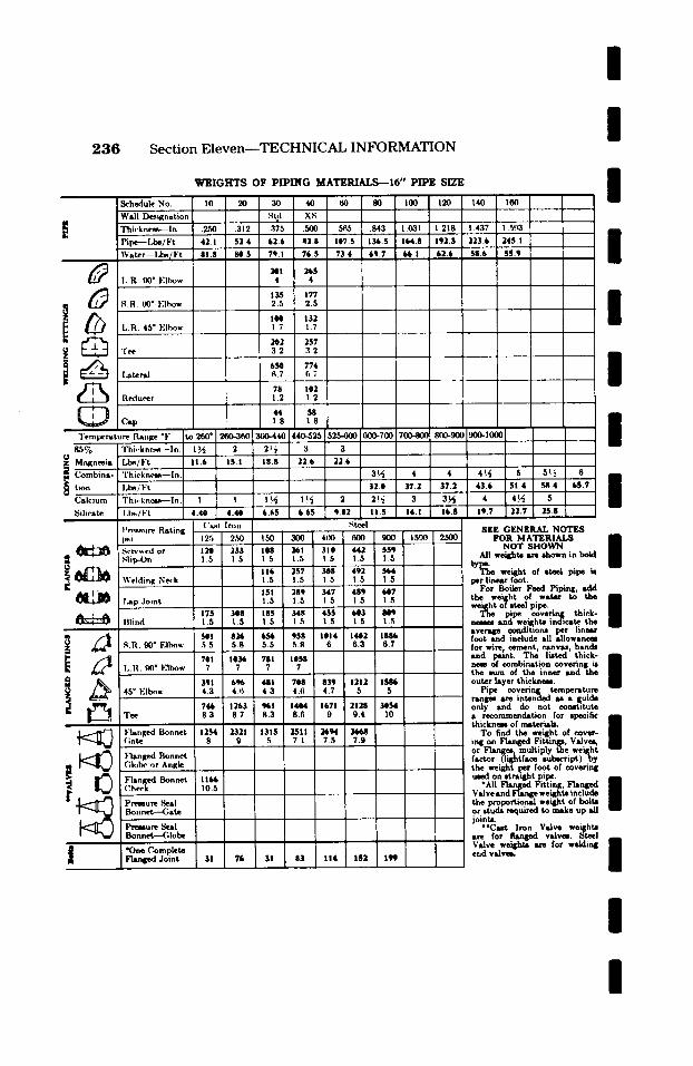
/
236 Section Eleven--TECHNICAL INFORMATION / I
W E I G H T S O F P I P I N G M A T E ~ I 6 " P I P E S I Z E
m Schedule No. 10 20 40 60 100 120 140 160
Wall V~lgnat ion 0 Sial. XS Th ickne~- - In . .250 .312 .375 .500 .56,5 .843 1.031 ! .218 ! .437 I. 5'.k3
| , 1 ! ! t ! ! 1 P i p e - - l , b s / F t 42. I 52 4 62 .6 82 .8 107.5 136.5 164.8 192.3 223 .6 245. I
J 6 O ! V i L W a t e r - - L b ~ [ F t 8 1 . 8 8 0 . 5 7 q . I 7 6 . 5 7 3 . 4 6 9 . 7 i ~ . l * 6 2 . 6 5 8 . 6 $ 5 . 9 v
i I,.R. 90 ~ l.'lbow 4 L i J , o ,i, ! ~
S.R. 90 ~ Elbow 2.5 2.5 : . . . . . . 104 132
L.R. 45 ~ Elbow 1.7 1.7 A o I I, ! ! 1
i 2O2 257 �9 Tee i . 3.2 3 2 , , , t v
I.~teral 6.7 G.7 i I, | , t - 4 , ! !
78 102 I Reducer 1.2 1.2 !
! ! 1
i , ! T - ~,,,~, c'/o i Thi,-knc,~-~--I n. 1 ~ , 2 26~ , 3 3
t , i I, 1
Combina- L "l'hickncs~--In. i , , 3 ~ 4 5 5n.~ 6 ! ! ! ! ! tion Lbs /F t , 32.8 37.2 3 2 , S1.4 $8.4 65.7
Calcium , Thi, knce~--In. ! , ! !1~ , 1!4 2 2!~ 3 ~ 4 4 ~ .
Silicate l . l~ l Ft 4.40 4.40 6.65 665 9.02 i i L_ I ' r ~ u r e Rat ing ( ' ~ t I ron . . . . .~tcel , SEE G E N E R A L N O T E S
, psi 12.5 2.50 150 300 4(10 600 900 1500 2500 F O R M A T E R I A I ~ n ~. r~wedor ' 120 * 233 ' 108 * 261 ' 310 ' 442 ' 559 ' ~ " NOT SHOWN
B .~lip-On 1.5 1.5 1.5 1.5 1.5 1.5 1.5 All weights am shown in bold . . . .
116 257 308 492 564 t ~ weight of 0reel pipe is Welding Ne~.k !.5 i !.5 15 1.5 1.5 per ~ foot.
For Boiler Feed Piping, ~ . ~ 151 289 347 489 647 the weight of water to tlm I
laLp Joint ! .5 1.5 1.5 1.5 1.5 , , weight of steel pipe. ' 1 7 5 ' 348 185 ' .~1r * 455 * 6@3 ~ ' The pipe coveting thiek- l IHind 1 5 1.5 1.5 ! .S 1.5 1.5 i I ..5 ncmcs sad we~hts indicate tho
i ~ I ' '~ averNle ~r per l i n e r i 581 82~b 656 958 I014 1642 1886 foot and include all allowances S.R. 90 ~ Elbow .5.5 5.8 5.5 .5.8 6 6.3 6.7 for wire, cement, canve:,, bands
L . . . . . . . , ' sad psint. The listed thick- I 701 1036 781 1058 i I , .R. 90 ~ F lbow 7 7 7 7 theneSs sum~ combinatiOnof the innercoVeringsad thei* I / ~ ' 391 6 % 481 708 I 839 1212 1586 outer layer thickness.
45 ~ E|b~w 4.3 4.6 4 3 4.6 4.7 5 5 Pipe covering temperature . . . . . . . . ' ' r a n l ~ sre intenr u a guide
~ . . 746 1263 %1 14@4 1671 2128 34)54 only and do not constitut~ Tee i 8.3 8.7 8.3 8.6 9 9.4 I0 a recommendation for specific n
I , t h i c k n ~ of mter~-_~, I Flanged Bonnet 1154 2~21 1315 2511 2tq~ 3668 To find the weight of cover- I (;ate 8 9 5 7.1 7.5 7.9 ~ ing on Flanged F i t t i np , Valves,
. . . . . . . . . or Flanges .mul t ip ly the weight Flanged Bonnet factor (lightface subscript) b y
~ ~ Globe or Angle ' the weight pe~r. foot of covering I used on ,tmqlhtpipe.
Flanged Bonnet 1166 *ALl ~ Fitting, Check _ _ 10.5 Valve and Flange weights include
I" Pressure Seal the proportional weight of bolts Bonnet - -Gate or studs required to make up sU
, * * , * , , ; ; jo ints. Pressure Seal **Cast Iron Valve we~hts
"- * Valve ~ am for welding I * O , Complete I I ead v, lvc, .
Flanged Joint 31 76 31 83 114 IS2 199
I /

/
I / /
I / / / / / / / / / /
Schedule No I ~ Wall l)e, dgnat, m
I~ q'h wkm.~,~ -1,. g Pipe -l.t~, l"t ~ 474
Watcr--l.b../F~
~ I..R. 90" EIb,,- ] t " 1
i L.R 45 ~ Et~ .... & !
~ Tee ~
Reducer ] ~
_ _ ~ ~ c,p__L____ J Temperature Range OF
85% Thicknesa--ln. z O Magn~ia Lb~,, Ft g Thi,.kne~--ln IM ~ tinn Lbs, Ft
Cal,'ium Thickness- In. Silicate I,b,, l"t
Pressure ltatmg psi ~rewed or Slip-On
~ ~ Welding Neck
Lap Joint
I ~ , l i n d
~ ~ - - ~ .~ R. 90 ~ Elbow
I L.R 90 ~ Elbow
45* Elbow
l.'Isnged Bonnet Gate
["~n~d Bonnet Globe or Angte
r ~ ~ Pn~u~ Seal Bonnet---Gate
Pressure 8r BOn net--G Io . . . . . . . . . . . . bebe
i "One Complete Flanged Joint
Sec t ion E l e v e n - - T E C H N I C A L I N F O R M A T I O N 2 3 7
W E I G H T S OF PIPING MATERIALS-- 18" PIPE SIZE
i i i
1
('a.st I ron I .~tevl SEE GENERAL NOTES
FOR MATERIALS NOT SHOWN
All weq~hts are shown in bold
tY~l~e" weight of steel pipe is per linear foot,
For Boiler Feed Piping, add the weight of water to the weight of steel pipe.
1'he pipe covering thick- nmses and we,'~hts indicate the sversgv condittorm per linear foot and include all allowanom for wire, cement, canvas, bands and paint. The listed thick- ncm of combination covvring is the sum of the inner and the outer layer thiclmem.
Pipe covering temperature ranges are intended ms s guide only and do not oonst,tute a rvoommendation for specific thickncm of materia~
To find the weight 0[ cover- ing on Flanged Fittings, Valves, or Flanges, "multiply the weight factor (light/ace subscript)by the weight I~. foot of oovering used on straight pipe.
"All Fhu~vd Fitting, F1angvd Valve and Flange weights include the proportional weight of bolts or studs required to make up all joints.
"'Cast Iron Valve weights are for flanged valves. 8reel Valve weights are for welding end valves.
/

/
2 3 8 S e c t i o n E l e v e n - - T E C H N I C A L I N F O R M A T I O N /
i Schedule No. Wall D~ignation Th iek m ~ . - - I n .
. I'ipe--l,bs, Ft W a t e r - - l , h ~ / F t
I,.R. 90" Elbow
L.R. 45" Elbow
~ Tee
~ ~ Reducer
Cap
Temperature Range ~ 85% l Thickness--In
Z O- M ~ I , b s / F t
tio__.~r l,be/Ft Calcium Thickness--In. Silicate l,ba/Ft i
Pressure Rating psi Screwed or slip~)n
~ Welding Neck
Lap Joint
Blind
45 ~ Elbow
i,, ,q
Flanged Bonnet Gate
~ Flanged l~nnet Globe or Angle
Flanged Bonnet ~. Check
�9 ~ ~ l'res,su re Seal Bonnetr--Gate
Pre.~ure Seal Bonnet--Gh~be
8 *One Complete F'tanged Joint
WEIGHTS OF PIPING M A T E R I ~ 2 0 " PIPE SIZE
St~,el
i
i I
=
/ / / / / /
SEE GENERAL NOTgS FOR MATERIALS
NOT SllOWN I All weights are shown in bold
tYti?l~e" weight of steel pipe is per linear foot.
For Boiler Feed Piping, add the weil~ht of water to the weight ol ~teel pipe. I B
The pipe covering thick- / n e ~ s and weights indicate the average conditions per linear foot and include all allowancea for wire, cement, canvas, bandit and paint. The listed thick- nesa-of combination covering ia / the sum of the inner and the / outer layer thickness.
Pipe covering temperature ranges are intended as a guide only and do not constitute a recommendation for specific thickness of materiats.
To find the weight of cover- ing on Flanged Fittings, Valve, | or Flanges, multiply the weight factor (lightface subscript) b y the weight per foot of covering tL~d on stralghtpipe.
[ "All lqanged Fitting, FLanged _ ~ Valveand Flange weights include /
the proportional weight of bolts or studs required to make up all
' joints. �9 "Ca~t Iron Valve weighta
are for flanged valves. Steel j alve weighta are for welding
end valvm.
I / /
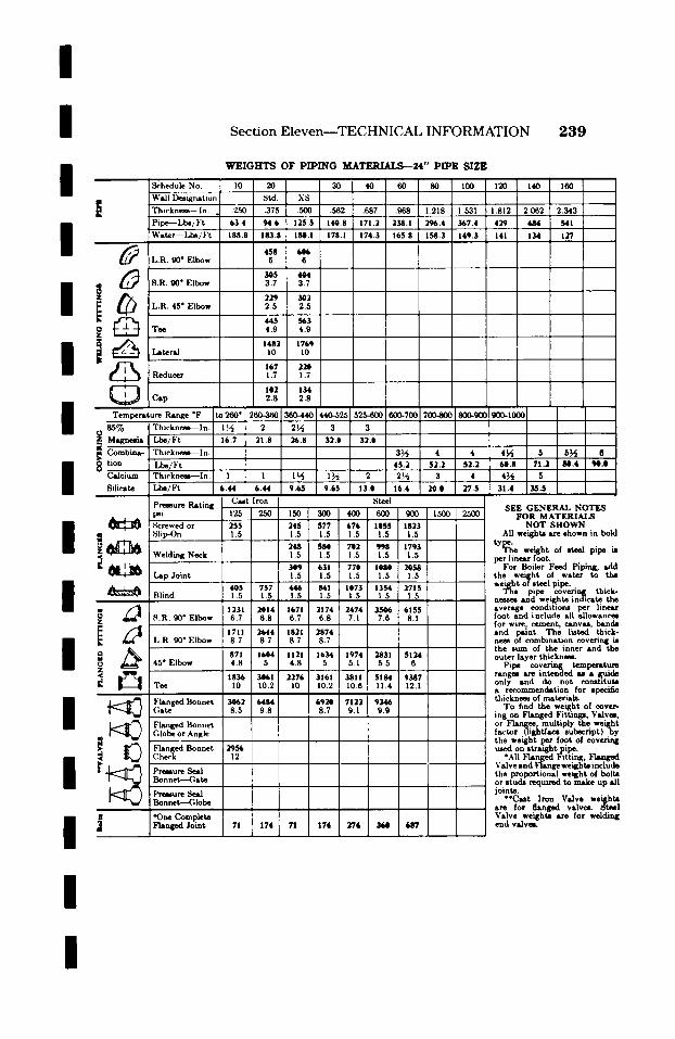
/
/ Section Eleven--TECHNICAL INFORMATION 2 3 9
/ /
/
/
/
/
/ / /
/
/
/
Schedule No. I)eaignation
E ~ Pipe----Lb./Ft Water--Lb~i Ft
L.R. 90" Elbow
g 8.R. 90" Elbow
"L.R. 45" Elbow
Reducer
Cap
Temperature RAnge ~ t
8 5 ~ Thicknem--In. I ~ Magncma Lbe/Ft j
Thieknem--In.
8 ~ Silicate I .~ /Ft
Premure Rating psi ~rewed or Slip-On
i ~ Welding Neck
~ .Lap Joint
~ Blind...._ d_...__~.
i L.R. 90* Elbow
45" Elbow
~ Flanged Bonnet (;ate
Globe or Angle
F h m Bonnet
Pressure Seal Bonnet---Gate
Pressure Seal Bonnet--Globe
W E I G H T S OF PIPING MATERIALS- -24" P IPE SIZE
8reel SEE GENERAL NOTES
FOR MATERIALS NOT SHOWN
All weights are shown in bold
tY[~l~e"~ weight of steel pipe is per linear foot.
For Boiler Feed Piping, add the weight of water to the weight of steel pipe.
The pipe covering thick- neaes and weights indicate the average condtUons per linear foot and include all allowances for wire. cement canvas bands i ~ . ~ . and paint. The lmted thmk- ne~ of combination covering is the sum of the inner and the outer layer thickness.
Pipe covering temperature ranges are intended al a guide only and do not constitute a recommendation for specific thicknesw of materials.
To find the weight of cover- ing on Flanged Fittings, Valves, or Flanges, multiply the weight factor (lightftce subscript)by the weight per foot of covering used on straight pipe.
"All Flanged Fitting, Flanged Valve and Flange weights include the proportional weight of bolts or studs required to make up all joints.
"'Cast Iron Valve weights are for flanged valvr Steel Valve weights are for welding end valveL
/
I
/
2 4 0 S e c t i o n E l e v e n - - T E C H N I C A L I N F O R M A T I O N
HANGER LOAD CALCULATIONS
T h e thermal deflection of piping in modern high pressure and high temperature power stations has made it necessary to specify flexible supports, thereby requiring the designer to give considerable thought to the calculations of hanger loads for the steam pipe lines. Most manufacturers of power station equipment place limitations on the allowable loads at terminal points. Boiler and turbine manufacturers are especially concerned about the pipe weight on their equipment and sometimes specify that the reactions at pipe con- nections shall be zero. Piping engineers are interested in knowing the proper procedure to follow in calculating the loads at various points of support on a pipe line and also to determine the position of support on a pipe line where the pipe load at the anchor or terminal point is limited.
Pipe lines should be supported so that the load on the terminal points is not greater than the allowable load throughout the full range of thermal expansion.
Therefore, it is desirable to know the supporting force at each pipe suspension point and to have the total supporting forces equal to the calculated weight of the piping system.
With these conditions in mind, it is quite evident that the pipe support engineer has l~eed for a method of calculating the supports that will be clear, concise and easily understood.
In the example problems to follow it is assumed that the hangers have been located. The approach and the assumptions made in solving a hanger load problcm could be numerous, depending on the designer. The solution that follows is not intended as being the only method but rather as a method of producing a good balanced system for the problem under consideration. Of the approaches that could be made in the solution of any problem there will be one solution that produces the best balanced system. Individual loads will very likely be different but the total of each combination of hanger loads plus reactions obtained should be approximately the same in every case.
A well balanced suspension system will result in values for the loads on the hangers to be in close proximity to one another provided all pipe is of the same size or there are no highly concentrated loads located near a hanger; where there are concentrated
/
m loads within the system the supporting forces required
of the adjacent hangers will be correspondingly m large. |
Figure 1 illustrates a pipe line drawn in isometric with all the necessary dimensions shown in the same plane as the related section of pipe. This illustration is mm
limited to as few pipe sections as possible but incorpo- | rates most of the problems commonly encountered in power station piping support. The type of support, spring or rigid, is not covered here as this is a function mm
of the piping system's thermal deflection and should be m treated as a separate study. m
The first step in the solution of a problem of this kind is to prepare a table of weights. Such a table, for the m pipe line shown in Figure 1, is given on the following m
m page. Calculation of loads is accomplished by taking
moments about an unknown value and solving for a m
second unknown value, or if all loads except one are m known, summation of the individual loads will produce II the unknown load. It is preferred in this explanation that the summation method be used as check method on the accuracy of the computations made in the moment m
m
method. | The calculation of loads for hangers of a piping
system involves first dividing the system into conven- ient sections at the following points in the system and m the order of preference is as listed: (1) Hangers, | (2) Bends (either vertical or horizontal), and (3) Risers.
The next step is to isolate each section for study m beginning with the section of pipe supported by | hangers H-I and H-2. The solution of each section should be prefaced by the drawing of a free body diagram. This will provide a clearer picture of the m steps involved in the solution. |
Section I I D r a w a single line sketch, preferably to scale, as in
Figure 2, and show all dimensions and weights. (The m weight should be shown at the center of gravity of each | piece of pipe, valve or fitting.)
T ~ ~ reprodm~d t ~ the ~ o/ O d n n ~ Co. Inc. /
l

/
/ Section Eleven--TECHNICAL INFORMATION
/
/ Figure 1
No, rg: Maximum AIh)wable Losd at B - 6501b
I Table of Weights
2 4 1
~ , o r 1 6 2
/ / /
/
De~nption
12~-Schedule 160 Pipe
6~ IN) Pipe
12~ Stop anti Ch,-ck Valve
12~ l,ap F~lsngle
12" X 12" • 6"-:,001~ Flanged Tee
12"-9001b F'htlig~| (;Site Valve
12"-,g<'hedule leO Weld 1.31
6~ Flange
6"-,.~hedule 160 W,.hl HI
6"-900~ Flanged Globe Valve
12"-9001b Flsnl~d Elbow
Weight in Pounds
161
45 3
39e0
445
16g3
4024
4 ~
!16
59
II00
159g
Insulation Weight in Pounds
3 6 5
24 2
3940
54 75
321 0
3 9 4 0
109 5
3 6 3
3 6 3
217.8
2263
Total Weight
...
197 5
69 5
4354 0
499 75
2O040
441~ 0
569 5
152 3
95 3
1317 8
18'24 3
Weight Used in Calculations Unit
197.5
6 9 5
4354 0
5000
20040
4418.0
570 0
152 0
95 0
1318 0
1824 0
Per Ft
Per Ft
Each
F_~eh
Each
Each
E~eh
Each
Each
Each
Each
/
I /

I 2 4 2 S e c t i o n E l e v e n - - T E C H N I C A L I N F O R M A T I O N
/ 4 { 6 4 ~K)O H-t
1 7.4111'
E ~1 II_l l l l l ' F
Figure 4
A. . , 151
1o J ]
force on H-I due to the line A-(H-I ) plus RH-i reacting st 0.
3.708 (H- 1 )" - 4354 (1.183) 4- 500 (3.291 )4-638(11.166) - 6s92.3s2 + 1645.5+ 7123.90s - 15,661.79
( H - I ) " - 4224m
Of
(H-!)" - 4354 + fd)0 + 638 - 1268 - 42241b
Total load on H-I - (H-I) ' -t- (H-I)" - 841 -t- 42'24- 50651b
Sect/on 2
Consider next the section d pipe between H-2 and H-3. Figure 5 shows the section in elevation with the loads indicated as in Figure 2. In this section we will consider Rs.2, which as yet has not been balanced.
The weight d the vertical bend is considered as acting at the center of gravity d the bend. Figure 3 can be used to determine this location.
C - 5 X 0.637 - 3.183' - 3'-2~"
All forces are in the vertical plane. Take moments about H-2, solve for (H-3)', the load
on H-3 due to the line (H-2)-(H-3).
14.5(H-3)' - -477(9) 4- 790(2) 4- 1550(7.187) 4- 3173(9) + 1550(10.183) 4- 99(14.25)
- -4293 4- 1580 4- 11,139.&5 4- 28,557 4- 16,760.15 4- 1410.75
- 55,154.75 (H-3)' - 380411>
Take moments about H-3 to solve for (H-2)", the load on H-2 due to line (H-2) to (H-3).
14.5(H-2)" - 99(0.25) 4- 1550(3.683) + 3173(5.5) + 1550(7.317)+ 790(12.5) + 477 (23.5)
- 24.75 + 5708.e~ + 17,451.5 + 11,341.35 + 9s75 + 11,2o9.s
- 55,610.75 (H-2)" - 38351b
or
(H-2 ) " - 99 + 1550 + 3173 + 1550 + 790 + 477 -- 3804 - 3835lb
Total load on H-2 -- (H-S)' + (H-2)" - 927 + 3835 - 47621b.
t . i L I t
4{~t
I : - f l " _ ~ I ' ~ I ' ~ L ~JSrJ_', I"l{
IOOO =
Fi lu~ 5
i
l i T ]
/
/
/
/ /
, / ' I r
, . / / Section $
The section of pipe between H-4 and H-,5 has an impoeed load of the 6 ~ line through the flanged tee. This load must now be determined and at the same time m solve for loads on Hangers H-6 and H-7. See F i g - / ure 6.
The load and the imaginary beam reactions for the 45 ~ bend are calculated as in Section 1. The load due to line (H-6)-Ru.7 results in the reaction Rs.7 which is to be carried by H-7. The load due to line | Ru.e-(H-7) results in the reaction Rx4 which is to be carried by H-6.
Taking moments about H-6 solve for RR.7, me Irgu re 7. /
2Ru.7 - 62(0.437) 4- 146(1.206) - 27.094 4- 176.368 - 203.462
R s . 7 - 102Ib /
/
/

/ /
S e c t i o n E l e v e n - - T E C H N I C A L I N F O R M A T I O N 2 4 3
/ g,
w z o
ttJ =g 0
I : z
Q
/
l l l l l T l l l l l l l l l l l l ~ L ~ l l l l l ] I l l l l l l ~ J | I l I l l l ~ l l l I l l l I ]
CALCULATED ARC ~STANGES FOR I.I ~ USE WITH HORIZONTAL BENDS I [ 1 1 1 . . . .
AND WELDING ELBOWS . . . . . . . . . l l l l l l i l l l I l I i l i
I l l I l l l I i I l l l l l l [ ~ I I I I l l l 1 I I I ! I I [ [ I l l l l l I ~
_ L [ I I I I I I I l i l I ] ~ i
e IN DEGREES IO0 I10 120 ~K) ~ 0 I lK) lit0 170 I1~
i i ,.,
- 1.0
1 1 - L.
.6 I I _ I I I I . 1 ,I
I ii ,.
ii ii rl
I - . 2 t
,. . |
! : 100 II0 I~0 130 140 ~ I~0 170 100
/
/ I
/ . / " /
0 10 20 30 40 50 60
I I | I I W ~ | I I m l | | f J l l l i I O I F | I l l i l l i J l l l l i l l e A l l l l l I I V . I l n l l I F d l l I l l l 1 4 8 1 1 1 1 1 1 ~ l l l l l l l l l l l l l l l l l I I I l l l l l l I I I I I I I I I I l l l l l l l l l l l l l l l l l I l l l l l l l l l l l l l l l l ( l l l l l l l l l l l l l l l l l l I l l l l l l l l l l l l l l l l l l l l l l l l l l i l l l l l l l l l l l l l l l l i l l l l l l l l l I l f l l l l l l l l l l P ~ d l l l P ~ d l l l l : d a g i i l U l l
70 eO gO
.8
.1'
.5
.4
0
CENTER OF GRAVITY OF AN ARC FOR USE WITH VERTICAL BENDS AND WELDING ELBOWS ~ ~ ~ 4 ~ ' ~ ; i ~ l l [ t i
, l [ I l l l l l l l l l l l l ~ r ' ~ . ~ l l l l l l l l l l l l l l l l l l I - l l l l l I ] I l l l I l ' l l l I I I i l l I l l l l I l l I ! J l l l l l I I 1 1 1 I I I 1 1 I I 1 1 I I ! I I
A" 2R ~ N e
O �9 R ( I - ~ e}
C# R S IN9 e
+H-H+F . ~ ~ l I l l l l ] I [ ! I ] i i - l ~ t l : l l l t - ~ - ~ ~ L L U I I I ] [ I 2 r ~ l l l l t l l t l Z l l l
, i i
j ~ l l | I l l l l I l | ; q l I l i [ l i i l I I & L 1 1 1 1 1 1 1 1 I I I I I 1
"1 l l l l l l l l l l l l l I 1 1 1 1 1 1 1 I I I I I I I .
I 1 1 1 1 1 1 1 1 1 1 1 ; I 1
I I I m i m I I i m I I p~ i l l I l l i l l i | | | |
H I I i l l
B 0 I0 20 30 40 50 60 TO 80 90
H H D I I H I I I I I I I I I I I I I I H I m m m q m m l l l m m m m m m
I = I I | : , , ~ ,= I I | I | l i g i O i l m m i l l l l l i j i m m m m l i l i l m l n m B o i o o i o g l o m m O l O l O O l i l i m o l n m m g e e m g e n n l n u e I O H O O O O O D H H i i l l l a m e l i m i l l l m l p m B m m m o m i o o | i . ~ ' l l i l l l i i l l O i l = a l ~ : i l U l f l l l I l l h = ; ' q l H I I I l l l l l l l l i . q q l l l l l l l l l l l l l f l l i . ~ I l l l l l l l l l f l H I I H I I I I I I H I I I H I l I I I l l l l l l I I I I I I I I I I l i l i I l l l l l l l l l l l l l I l l l l l l l l l l l l l I l l l l l l l l l l l l l I l l l l l l l l l l l l l l l l l l l l l l l l l l l I l l l l l l l l l l l l l I l l l l l l l l l l l l l I l l l l l l l l l l l l l I l l l l l l l l l l l l l I l l l l l l l l l l l l l I l l l l l l l l l l l l l I l l l l l l l l l l l l l I l l l l l l l l l l l l l I l l l l l l l l l l l l l I l l l l l l l l l l l l l l l l l l l l l l l l l l l
1.0
I | | D | | | B | | D O I I I I l l l i l l l l m l ~ q O O O m O l O O U O | l b ~ B O i B i O g U m n i n m : m i m i l i i n n l g g n b ~ g U m e n m l l e l l i l ~ q O l l l i l g n n n i i h ~ O l i | l m n B n l l i i ~ q O I I o n o l o o n o o l : q n m m o o o o m m a o b
.4
.2
. m i l l e i l m l l l n l I m m m 0
I00 IX) 120 130 140 l{K) 160 11'0 l l e
�9 IN DEGREES F~ure a
/ /
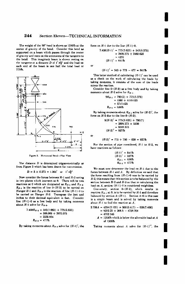
/
2 4 4 Section Eleven--TECHNICAL INFORMATION /
The weight of the 90 ~ bend is shown as 1550Ib at the center of gravity of the bend. Consider this bend as supported on a beam which passes through the center of gravity and rests on the extensions of the tangents to the bend. This imaginary beam is shown resting on the tangents at a distance D of 1'-4~ ~ and the load on each end of the beam is one half the total load or 7751b.
&
force on H-I due to the line (H-I)-4).
7.458(H-1)' = 775(3.625) + 543(6.375) - 2809 .375 + 3460.625 = 6270
(H-l) ' = 84ttb
or
(H-l ) ' = 543 + 775 - 477 - 84111)
/
/ This latter method of calculating ( t t -1) ' can be used
k \ / as a check on the work of calculating the loads by 1 �9 ' /~ .~___ taking moments, it consists of the sum of the hinds 1 ' ~ 43s4 minus the reaction.
~ ~. ~ Consider line 0-(H-2) as a free b(xty and by taking ; .L
2
.
-, :,f
R,, t
~ ~o H - I
R. 1 0
Y-r ' / t "
7gO
H-2
L ~ 3,~' ... J
Figure 2. Horizontal Bend--Plan View
The distance D is determined trigonometrically or from Figure 3 which has been drawn for convenience.
D - S X 0 . 2 7 3 = 1.365' or 1'-4�89
N o w consider the forces between H-I and H-2 acting in two planes which intersect at 0. There will be two reactions at 0 which are designated as Ru. t and Ru.2. Ru-t is the reaction of line 0-(H-2) to be carried on Hanger H-I and Ru.2 is the reaction of line (H-I) -0 to be carried on Hanger H-2. Transpose the feet and inches to their decimal equivalent in feet. Consider line (H-I)-0 as a free body and by taking moments about H-I solve for RH.#.
7.458Ru.2 = 543(1.083) + 775(3.833) = 588.069 + 2970.575 = 3558.664
R#.2 ffi 4771"o
By taking moments about RH.~ solve for (H-I) ' , the
moments about H-2 solve for Ru. t . n
9Ru. t = 790(2) + 775(5.375) B = 1580 + 41tk5.625 II - 5745.625
R U . t = 6,~81"0
By taking moments about Ru. t solve for (H-2)', the n force on H-2 due to the line 0-(H-2). $
9(H-2)' - 775(3.625) + 790(7) ffi 2809.375 + 5530 = 8339.375
(H-2)' = 927Ib
o r
(H-2)' - 775 + 790 - 638 - 927Ib
For the section of pipe. considered, H-I to H-2, we have reactions as follows:
(H-I) ' = 84lib (H-2)' = 92711)
R u . t = 6381"o Ru.2 = 477I"o
/ / /
We must now determine the load on H-I due to the forces between H-I and A. By definition we said that the force resulting from ( t t -1) -0 was to be carried by 1 H-2, this means that this .section is to be balanced by the | section between H-2 and H-3 so that in calculating the load on A, section (H-I)-4) is considered weightless.
Conversely, section 0-(H-2), which results in reaction Ru. t at 0, is to be carried by H-I and therefore n balanced by section A-(H-1 ). Section A-4) in this case | is a simple beam and is solved by taking momenta about t l -! to find the reaction at A.
3.708A = 4354(2.125) + 500(0.417) -638(7.458) n = 9252.25 + 208.5 - 4758.204 l = 4702.546
A = 12681b which is below the allowable load at A of 1500Ib
Taking moments about A solve for (H-l)" , the /
/
/
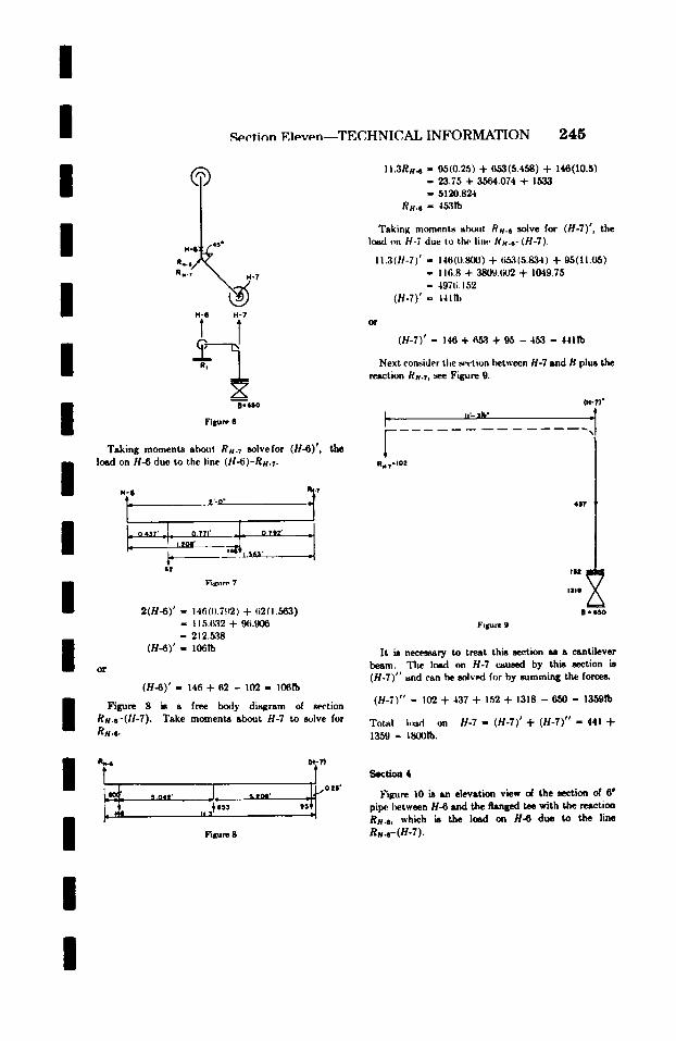
/
l / /
l / / /
,q~cticm Eleven--TECHNICAL INFORMATION 2 4 5
H So
. . . . I ,< , R..i ~ - 7
H-6
T H-?
B - ~ O
Figure 6
Taking moments aboqt RH.7 solve for (H-6)', the losd on H-6 due to the line (ii-6)-RH.~.
/ H-6 ~ V
0 431' _ c 0.711' _ _ 0 ? l / ' I . lO l '
. . . . . f
/ l o r
F i l o l r r 7
2 ( H - 6 ) ' = 146(().7~Y2) + l i2(1.563) = I 15.~tq2 + g6.906 = 212.5~8
(H-O) ' = 106ro
(H-6)' - 146 + 62 - 102 - 10611)
Figure 8 is a free b(xly diagram of section Rli-s-(H-7). Take moments about H-7 ix) solve for Rs.6.
m Y S_O41' J . , S.lOQ'
II 1 It 653
04-7}"
T ~ G l $ '
,;;J Figure 8
11.3R,4 = 95(0.25) + 653(5.458) + 146(10.5) - 23.75 + 3564.074 + 1533 - 5120.824
R H .6 " 4531b
Taking moment~ l t l ~ i l RH.6 solve for (H-7)', the load on H-7 due to the lille I/s.~-(H-7).
11.3(H-7)' - 146(0.800) + ti~3(5.834) + 95(11.05) - 116.8 + 3809.1i02 + 1049.75 = 497ti. 152
(H-7)' - 4411b
o r
(H-7)' - 146 + 653 + 95 - 453 - 4411b
Next consider the ,~.~.tion between H-7 and B plus the reaction Re.7, see Figure 9.
I_ 11'- ] h?
F _ _ .
R,,.T'IOZ
{H-T)" _l _
- - -,,,, %
4111'
Figure 9
IIIIII y
B m$~
It is necessary to treat this section as a cantilever beam. Tile load on H-7 cemsed by this section is (H-7)" and can be solved for by summing the force~
( H - 7 ) " - 102 + 437 + 152 + 1318 - 650 - 13591b
Total h~d on H-7 - (H-7)' + (H-7)" - 441 +
1359 = 18001b.
Section t
Figure 10 is an elevation view d the section of 6" pipe I~tween H-6 and the flanged tee with the reaction Rs4, which is the load on H-6 due to the line
Rs4-(H-7).
/ /
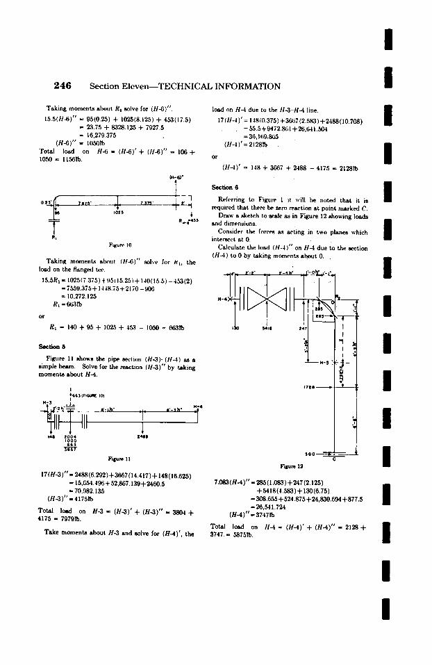
/
2 4 6 Sect ion E l e v e n - - T E C H N I C A L I N F O R M A T I O N /
Taking moments about R~ solve for (tl-6)".
15.5(!1-6)" - 95(0.25) + 1025(8.125) + 453(17.5) = 23.75 + 8328.125 + 7927.5 = 16,279.375
(H-6)" = 1050Ib Total load on H-6 = (H-6)' + (H-6)" = 106 + 1050 = 11561b.
T R,
?It?S* J_ T3/~' I 0~5
Figune l0
04-6) ~
R~6-453
Taking momenta about (I!~)" solve for ~1, the load on the flanged tee.
15.5R, = 1025(7.375)+95( 1,5.2,5)+ 140(15.5) -453(2) = 7559.375+ 1448.75+2170 -906 ffi 10,272.125
R, = 6~3 ro
o r
Rl = 140 + 95 + 1025 + 453 - 1050 = 663P0
Section 5
Figure 11 shows the pipe. section (H-3)-(1t-4) as a simple beam. Solve for the reaction (H-3)" by taking moment8 about H-4.
I 4i 5G 3 (F,G4.~ ool I
H - 3 j . - , , ,
II 140 ZOO4 IO00 663 l-t 'gT
Figure l I
7-
i t4,011
s'-3~"
17 (H-3)"= 2488(6.292)+3667 (14.417) + 148 (16.625) -- 15,C~54.496 + 52,867.139+ 2460.5 - 70.982.135
( H - 3 ) " - 4175ro
Total load on H - 3 = ( H - 3 ) ' + ( H - 3 ) " = 3 8 0 4 + 4175 = 79791b.
Take moments about H-3 and solve for (H-4)', the
load on H-4 due to the !1-3-H-4 line.
17 (tl-4)' = 148(0.375) + 364;7 (2.583) + 2488(10.708) = 55.5+9472.801 +26,641.504 = 36, I(i9~865
(11-4)' = 21281b
o r
(H-4)' = 148 + 3667 + 2488 - 4175 - 21281"0
Section 6
Referring to Figure 1 it -'ill be noted that it is required that there be. zero reaction at point marked C.
Draw a sketch to,scale as in Figure 12 showing loads and dimensions.
Consider the forces a.s acting in two planes which intersect ~t 0.
Calculate the I(~xl (H-4)" on H-4 due to the section (H-4) to 0 by taking moments about 0 . .
54o0 24i ~ -5 ,
17tO
Figure 12
5 0 0
/ /
I i
�9 I /
I I /
/ 7.083 ( H - 4 ) ' - 285(1.083) + 247 (2.125)
+ 5418(4.583)+ 130(6.75) - 308.655 + 524.875 + 24,830.694 + 877.5 - 26,541.724
( H - 4 ) ' - 37471b
Total load on H - 4 = ( H - 4 ) ' + ( H - 4 ) " = 2 1 2 8 + 3747. = 5875Ib.
/ /
/ /
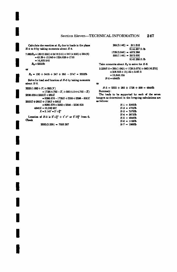
/
I / /
I I I I I I / / /
I /
Sect ion E l e v e n - - T E C H N I C A L INFORMATION 2 4 7
Calculate the reaction at Rs due to loads in the plane H-4 to 0 by taking moments about H-4.
7.083Rs - 130(0.333) + 5418(2.5) + 247 (4.958) + 285(6) - 4 3 . 2 9 + 13,545+ 1224.626+ 1710 - 16,522.916
Rtl - 130 -t- 5418 + 247 + 28,5 - 3747 - 23331b
8olve for load and location of H~5 by taking momenta about H ~ .
~(Z.0S3+X)+2SS(X) - 1728(4.792 - X ) +500(4.5-}-4.792 - X )
2526.639+ 2333X + 285X - 8280.576 - 1728X + 2 2 5 0 + 2 3 ~ - 500X
~&3,3X + 285X + I 728X + 500X - 8280.576+22.50+2396 - 2526.639
4 8 4 6 X - 10,399.937 X - 2.146' - 2'-1 ~"
Loeatkm d H-5 k 2C1~" + 1~-1" or 3~-2~" from 0. Cheek
2333(3 .229) - 7533.257
2ss(~.t4e)- 6z1.6~o 8144.867 ft Ib
1728(2.646) - 4572.288 500(7.146) - 3573.000
8145.288 ft Ib
Take momenta about Rz to solve for H-&
3.229H-5 - 285(1.083)+ 1728(5.875)+500(10.375) -308.655+10,152+5187.5 - 15,648.155
H-6-48461b
H ~ - 2333 + 285 + 1728 -4- 500 - 4S461b Sumner: The loads to be supported by eae~ d the seven
hangers M determined in the foregoing r are u follows:
H-I - f~651b H-2 - 47621b H - 3 - 79791b H-4 - 58751b H~5 - 48461b H - 6 - I1561b H - 7 - 180011)
/
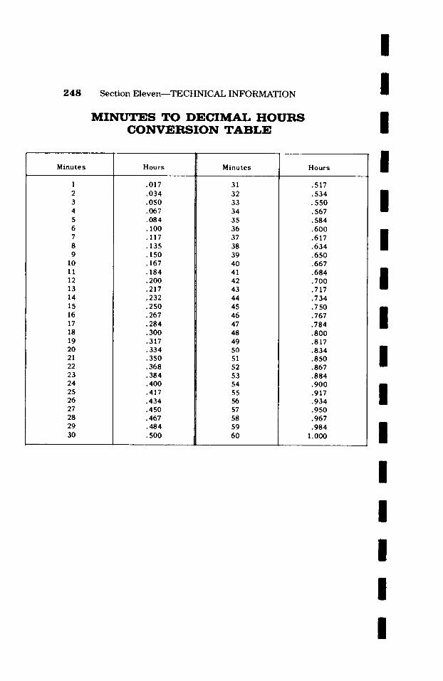
248
M i n u t e s
1 2 3 4 5 6 7 8 9
10 I1 12 13 14 15 16 17 18 19 20 21 22 23 24 25 26 27 28 29 3O
S e c t i o n E l e v e n - - T E C H N I C A L I N F O R M A T I O N
M I N U T E S T O D E C I M A L H O U R S C O N V E R S I O N T A B L E
H o u r s
.017
.034
.050
.067 �9 084 �9 100 .117 �9 .150 .167 .184 �9 200 .217 .232 .250 .267 .284 �9 300 .317 �9 334 .350 �9 368 �9 384 �9 400 .417 .434 �9 �9 467 .484 �9 500
M i n u t e s
31 32 33 34 35 36 37 38 39 40 41 42 43 44 45 46 47 48 49 50 51 52 53 54 55 56 57 58 59 60
H o u r s
.517
.534 �9 550 .567 .584 .600 �9 .634 .650 .667 .684 .700 .717 .734 .750 .767 .784 .800 �9 . 834 .850 .867 .884 .900 .917 .934 �9 .967 �9
1.000
/
I I / / / / /
II
II
II / /
II / /

I I I I I I I I I I I I I I I I
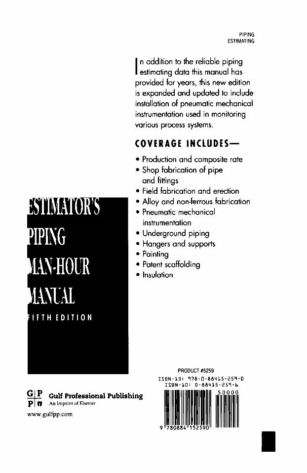
PIPING ESTIMATING
I n addition to the reliable piping estimating data this manual has
provided for years, this new edition is expanded and updated to include installation of pneumatic mechanical instrumentation used in monitoring various process systems.
COVERAGE INCLUDES--
G P P o
Gulf Professional Publishing An Imprint of Elsevier
www.gulfpp.com
�9 Production and composite rate �9 Shop fabrication of pipe
and fittings �9 Field fabrication and erection �9 Alloy and non-ferrous fabrication �9 Pneumatic mechanical
instrumentation �9 Underground piping �9 Hangers and supports �9 Painting �9 Patent scaffolding �9 Insulation
PRODUCT #5259 ISBN-13: 978-0-88415-259-0
ISBN-10:0-88415-259-6
80884 152
50000
//