Embed Size (px)
Citation preview

This work was supported by the US National Science Foundation under the Grant EFRI #0836017.
2010 IREP Symposium- Bulk Power System Dynamics and Control – VIII (IREP), August 1-6, 2010, Buzios, RJ, Brazil
Estimation of Voltage Stability Index in a Power System with Plug-in Electric Vehicles
K. Joseph Makasa
Real-Time Power and Intelligent Systems Laboratory
Missouri University of Science and Technology Rolla, MO 65409, USA
Ganesh K. Venayagamoorthy Real-Time Power and Intelligent Systems
Laboratory Missouri University of Science and Technology
Rolla, MO 65409, USA [email protected]
Abstract A Multilayer Perceptron (MLP) neural network based approach for estimation of the voltage stability L-index in a power system with Plug-in Electric Vehicles (PEVs) is presented. This technique overcomes the limitations of direct calculation of L-index from measurements at a load bus. The L-index calculation is dependent upon the no-load voltage phasor for any given system topology and operating condition. In practice it is difficult to obtain no-load voltage phasor at a bus each time the system topology or operating point changes. An MLP neural network based method capable of estimating voltage stability L-index at a load bus using direct measurements and that does is independent of the no-load voltage phasor of the bus is presented. Results show that the MLP accurately estimates the voltage stability L-index for different cases of system topologies and operating conditions. Introduction Power system voltage stability has become an issue of great concern for both power system planning and operation in recent years, as a result of a number of major black outs that have been experienced in many countries due to voltage stability problems [1,2]. This has been mainly due to power systems being operated closer to their stability limits because of increased demand for electricity [1]. Many studies have been carried out done to determine voltage stability indices in order to take necessary action to preclude eminent instability and thereby improving voltage stability in a power system. References [3, 4] present comparative studies and analysis of six different voltage stability indices, while [5] introduces the voltage stability L-index to be a simple but effective means of measuring the distance of a power system to its stability limit. The disadvantage of using the L-index, is that its calculation depends upon the no-load
voltage phasor at the load bus for a given topology of the system. Since the no-load voltage is dependent upon the system topology and operating point, it varies as the system topology or operating point changes. In practice it is difficult to obtain no-load voltage at a bus. The proposed Multilayer Perceptron (MLP) approach capable of estimating the L-index without directly obtaining the no-load voltage overcomes this limitation of and facilitates on-line determination and use of L-index. The electric power grid is rapidly growing and demanding new technologies for efficient and rapid control in order to ensure reliable and secure power networks [6]. Reference [7] carries out a study of the impact of Plug-in Electric Vehicles (PEVs) parking lots (SmartParks) on the stability of a power system. In particular, the study shows voltage characteristics following changes in power demand of PEVs. When PEVs discharge into the power network, system voltage support is enhanced, while charging action is accompanied by voltage drop in the load area. The method for estimation of voltage stability L-index developed in this study is applied for monitoring voltage stability in a power system with SmartParks included. Power System with Plug-in Electric Vehicles Figure 1 shows the 11 bus voltage stability test system with plug-in electric vehicle parking lots models included. The power system consists of two generators, G1 and G2 supplying the load area through five long (200km) parallel transmission lines, and one local generator, G3 providing voltage support in the load area. Bus 11 is a voltage controlled bus using an on-load transformer tap changer. System parameters and loading conditions of the system used in this paper are those given in Appendix E of reference [1]. The original system with 10 buses was modified by adding two SmartPark buses 12 and 13.
978-1-4244-7465-3/10/$26.00 ©2010 IEEE

5
Infinite Bus
G1
13.8 kV
1
500 kV
G2
13.8 kV
2
G3
13.8 kV
3
96
500 kV500 kV
11
10
Residential load
115kV
115 kV
7
200 km transmission lines
8
3000MW, 1800MVAr
13.8kV
PL7 PL8 PL9 PL10 PL11 PL12
SmartPark bus 12
2200MVA
5000MVA 1600MVA
13.8kV
PL1
PL2
PL3
PL4
PL5
PL6
3000MW
Smar
tPar
kbu
s 13
Industrialload
Fig. 1. Power System with plug-in electric vehicle parking lots (SmartParks).
The nominal (industrial) load at bus 8, load is 3000MW, 1800MVAr modeled as a constant power load, while load (residential) at bus 11 is 3000MW modeled as constant power load. Plug-in electric vehicle parking lots represent six SmartParks at bus 12 and 13 with capacity +/-180 MW each. Bus 8 is a load bus located in an industrial area and bus 11 is a load bus in a residential area. Voltage Stability Index Estimation Reference [8] presents the formulation of a voltage stability load index at a load bus using voltage equations. The technique uses measurements of voltage phasors and no-load voltage at the bus to calculate the voltage stability L-index. The complete mathematical derivation of the L-index is presented in the Appendix. The index gives the distance of the bus to the voltage stability limit. The voltage stability L-index is given by the equation:
( ) ( )[ ]
20
L022
LL0L0
VθθcosVθθcosVV4 −−−=L
……......(1)
Where, Vo is the no load voltage at the node and VL is load voltage. When the value of L at every load bus in the system is less than 1.0, the system is voltage stable. As the value of L approaches 1.0 at any bus, the system approaches its stability limit and becomes unstable when L is exceeds 1.0 at the referred bus [8]. VSI Estimation using a Multilayer Perceptron A feedforward multilayer perceptron neural network can be used to estimate voltage stability L-index at a bus. Equations (12) to (16) in the Appendix show that voltage
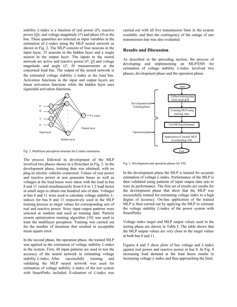
stability L-index is a function of real power (P), reactive power (Q), and voltage magnitude (V) and phase (θ) at the bus. These quantities are selected as input variables in the estimation of L-index using the MLP neural network as shown in Fig. 2. The MLP consists of four neurons in the input layer, 35 neurons in the hidden layer and a single neuron in the output layer. The inputs to the neural network are active and reactive power (P, Q) and voltage magnitude and angle (V, θ) measurements at the concerned load bus. The output of the neural network is the estimated voltage stability L-index at the load bus. Activation functions in the input and output layers are linear activation functions while the hidden layer uses sigmoidal activation functions.
.
.
.
.
.
θ
V
P
Q
L-index
Hidden layer
Output layerInput layer
Fig. 2. Multilayer perceptron structure for L-index estimation. The process followed in development of the MLP involved two phases shown in a flowchart in Fig. 3. In the development phase, training data was obtained, with no plug-in electric vehicles connected. Values of real power and reactive power at non generator buses as well as voltages at the load buses were taken with the load at bus 8 and 11 varied simultaneously from 0.8 to 1.2 load factor in small steps to obtain one hundred sets of data. Voltages at bus 8 and 11 were used to calculate voltage stability L-indices for bus 8 and 11 respectively used in the MLP training process as target values for corresponding sets of real and reactive power. Sixty input output patterns were selected at random and used as training data. Particle swarm optimization training algorithm [10] was used to train the multilayer peceptron. Training was carried out for the number of iterations that resulted in acceptable mean square error. In the second phase, the operation phase, the trained MLP was applied in the estimation of voltage stability L-index in the system. First, 40 input patterns are used to test the accuracy of the neural network in estimating voltage stability L-index. After successfully training and validating the MLP neural network was used for estimation of voltage stability L-index of the test system with SmartParks included. Evaluation of L-index was
carried out with all five transmission lines in the system available, and then the contingency of the outage of one transmission line was also evaluated. Results and Discussion As described in the preceding section, the process of developing and implementing an MLP/ESN for estimation of voltage stability L-index involved two phases; development phase and the operation phase.
Start
Training MLP usingtraining data
Test MLP performance
Application of trained MLPin estimating VSI
Collect training dataform smart grid
End
Development andTraining phase
Operation phase
Fig. 3. Development and operation phases for VSI. In the development phase the MLP is trained for accurate estimation of voltage L-index. Performance of the MLP is then validated using patterns of input output data sets to tests its performance. The first set of results are results for the development phase that show that the MLP was successfully trained for estimating voltage index to a high degree of accuracy. On-line application of the trained MLP is then carried out by applying the MLP to estimate the voltage stability L-index of the power system with SmartParks. Voltage index target and MLP output values used in the testing phase are shown in Table I. The table shows that the MLP output values are very close to the target values at both bus 8 and 11. Figures 4 and 5 show plots of bus voltage and L-index against real power and reactive power at bus 8. In Fig. 4 increasing load demand at the load buses results in increasing voltage L-index and thus approaching the limit.

Table I: Bus Load Flow and Calculated and Estimated Voltage Stability L-index
Bus 8 Voltage P(MW) Q(MVar) L-index
(Calculated) L-index
(estimated) (pu) (deg)
1.0470 -27.49 2960 -197.4 0.6311 0.6251
1.0444 -27.71 2971 -180.7 0.6381 0.6319
1.0417 -27.93 2982 -164.2 0.6450 0.6388
1.0391 -28.14 2993 -147.8 0.6519 0.6458
1.0365 -28.36 3004 -131.6 0.6587 0.6531
1.0339 -28.57 3014 -115.6 0.6654 0.6603
1.0313 -28.78 3025 -99.66 0.6720 0.6677
1.0287 -28.99 3035 -83.92 0.6786 0.6750
1.0261 -29.2 3045 -68.34 0.6851 0.6823
1.0235 -29.41 3055 -52.91 0.6915 0.6896
1.0209 -29.61 3064 -37.63 0.6978 0.6967
1.0183 -29.82 3074 -22.51 0.7041 0.7039
1.0157 -30.02 3083 -7.536 0.7103 0.7108
1.0132 -30.22 3092 7.282 0.7164 0.7176
1.0106 -30.42 3101 21.95 0.7224 0.7242
1.0081 -30.62 3110 36.48 0.7284 0.7308
1.0055 -30.81 3118 50.85 0.7342 0.7370
1.0030 -31 3126 65.08 0.7399 0.7431
1.0004 -31.2 3135 79.16 0.7457 0.7492
0.9979 -31.39 3143 93.1 0.7513 0.7549
0.9954 -31.58 3151 106.9 0.7568 0.7605
0.9929 -31.76 3158 120.5 0.7622 0.7658
0.9903 -31.95 3166 134.1 0.7676 0.7711
0.9878 -32.14 3173 147.4 0.7730 0.7762
0.9853 -32.32 3181 160.7 0.7781 0.7811
0.9829 -32.5 3188 173.8 0.7833 0.7857
0.9804 -32.68 3195 186.7 0.7883 0.7903
0.9779 -32.86 3202 199.6 0.7933 0.7946
Voltage decreases with increasing load. After 3200 MW bus 11 is the critical bus. Testing results have validated the MLP in accurately estimating voltage stability L-index of the power system. MSE obtained using an MLP: 8.7536 × 10⁻⁵. The trained neural network is used to estimate the voltage stability L-index of the 11 bus test system with SmartParks included at bus 12 and 13. In Figures 6 and 7, negative values of power represent charging of electric vehicles where real power flow is from the grid to the SmartPark and positive values of power represent discharging action where power flow is
from the SmartPark to the grid. Table II: Bus 8 Load Flow and Calculated and Estimated Voltage Stability L-index
Bus 11 Voltage P(MW) Q(MVar) L-index
(Calculated) L-index
(estimated) (pu) (deg)
1.0530 -33.81 2980 -963.9 0.5716 0.5704
1.0503 -34.08 2991 -959 0.5819 0.5810
1.0477 -34.35 3003 -954.1 0.5921 0.5918
1.0450 -34.62 3013 -949.3 0.6022 0.6021
1.0423 -34.89 3024 -944.4 0.6122 0.6124
1.0396 -35.15 3035 -939.6 0.6218 0.6221
1.0370 -35.41 3045 -934.8 0.6314 0.6320
1.0343 -35.68 3055 -930 0.6411 0.6417
1.0317 -35.94 3065 -925.3 0.6504 0.6511
1.0290 -36.19 3074 -920.5 0.6595 0.6603
1.0264 -36.45 3084 -915.8 0.6686 0.6693
1.0237 -36.7 3093 -911.1 0.6774 0.6784
1.0211 -36.96 3102 -906.4 0.6863 0.6873
1.0184 -37.21 3111 -901.8 0.6949 0.6959
1.0158 -37.46 3120 -897.1 0.7034 0.7045
1.0132 -37.7 3128 -892.5 0.7116 0.7128
1.0105 -37.95 3137 -887.9 0.7199 0.7212
1.0079 -38.19 3145 -883.3 0.7279 0.7292
1.0053 -38.44 3153 -878.7 0.7359 0.7374
1.0027 -38.68 3161 -874.2 0.7436 0.7452
1.0001 -38.92 3168 -869.7 0.7513 0.7528
0.9975 -39.16 3176 -865.1 0.7588 0.7604
0.9949 -39.39 3183 -860.7 0.7661 0.7675
0.9923 -39.63 3190 -856.2 0.7733 0.7749
0.9897 -39.86 3197 -851.8 0.7804 0.7817
0.9871 -40.09 3204 -847.3 0.7873 0.7885
0.9846 -40.32 3210 -842.9 0.7941 0.7951
0.9820 -40.55 3217 -838.6 0.8008 0.8016
0.9794 -40.78 3223 -834.2 0.8073 0.8080
0.9769 -41 3229 -829.9 0.8136 0.8141
0.9743 -41.23 3235 -825.5 0.8200 0.8199
0.9718 -41.45 3241 -821.3 0.8261 0.8255
0.9693 -41.67 3246 -817 0.8321 0.8312
Plots of the voltage stability L-index output of the MLP for a 24 hour period at bus 8 and 11 are shown in Figs. 8 and 10 respectively. Two different operating conditions of the power system have been considered: the first case

considers the system fully operational with no fault. In the second case the contingency with one of the five parallel transmission lines out of service is considered. The MLP estimated L-index outputs for these two cases are shown in Figs. 8 and 9.
2950 3000 3050 3100 3150 3200 3250 33000.94
0.96
0.98
1
1.02
1.04
1.06
Bus
Vol
tage
[pu]
Load [MW]
2950 3000 3050 3100 3150 3200 3250 3300
0.65
0.7
0.75
0.8
0.85
Vol
tage
Sta
bilit
y L-
inde
x
L-index
Voltage
Fig. 4. Plots of voltage stability L-index and voltage against real power for bus 8.
-200 -100 0 100 200 300 4000.94
0.96
0.98
1
1.02
1.04
1.06
Bus
Vol
tage
[pu]
Reactive power [MVar]
-200 -100 0 100 200 300 400
0.65
0.7
0.75
0.8
0.85
Vol
tage
Sta
bilit
y L-
inde
x
L-index
Voltage
Fig. 5. Plots of voltage stability L-index and voltage against reactive power for bus 8. At both bus 8 and bus 11, when the SmartParks are discharging, i.e. positive power, the voltage indices at the buses are lower.
This is when the SmartPark is providing power to the grid, hence helping to increase the system stability
margin. The parking lot is supplying additional power to the system (generating). When the SmartPark is charging
on the other hand, voltage stability index values are higher, indicating the system is less stable.
0 2 4 6 8 10 12 14 16 18 20 22 24
-120
-80
-40
0
40
80
140
180
Time [hours]
Pow
er [M
W]
Bus 8
Fig. 6. Smartpark power vaiation at bus 8.
0 2 4 6 8 10 12 14 16 18 20 22 24
-120
-80
-40
0
40
80
120
160
200
Time [hours]
Pow
er [M
W]
Bus 11
Fig. 7. Smartpark power vaiation at bus 11.
0 2 4 6 8 10 12 14 16 18 20 22 240.44
0.45
0.46
0.47
0.48
0.49
0.5
0.51
Time [hours]
L-in
dex
5 lines in service4 lines in service
Bus 11
Fig. 8. Estimate voltage stability L-indices with Smartparks included.
0 2 4 6 8 10 12 14 16 18 20 22 240.56
0.57
0.58
0.59
0.6
0.61
0.62
0.63
0.64
0.65
0.66
0.67
0.68
L-in
dex
Time [hours]
5 lines in service4 lines in service
Bus 8
Fig. 9. Estimated voltage stability L-indices with SmartParks included.

Thus system stability margin varies according to the operation of the SmartPark operation, of charging and discharging. The results also show that the system has lower values of voltage stability L-index, and hence more stable, with all five transmission lines in service. When one line is out of service, higher values of voltage stability L-index indicate that the system is less stable. This can be seen in the graphs of Figs. 8 and 9, where the graphs of L-index corresponding to the system with all five transmission lines in service as lower L-index values than that corresponding to the system with one of the five transmission line out of service. Conclusion A multilayer perceptron feedfoward neural network based approach for estimation of the voltage stability L-index in a power system with SmartParks has been presented. The presented neural network approach is independent of the no-load voltage at given bus. Real power, reactive power and voltage at load bus are sufficient measurements to estimate the L-index. Results show that the MLP approach is able to estimate accurately the L-index even with changes in topology and operating conditions. Future work involves demonstration of the proposed approach with PMU measurements. References [1] C. W. Taylor, Power System Voltage Stability, EPRI Power
System Engineering Series, McGraw-Hill, 1993. ISBN 0-07-063164-0.
[2] P. Kundur, Power System Stability and Control, EPRI Power System Engineering Series, McGraw-Hill, 1994. ISBN 0-07-035958-X.
[3] A. K. Sinha, D. Hazarika, “A Comparative Study of Voltage Stability Indices in a Power System”, International Journal of Electrical Power & Energy Systems, vol. 22, issue 8, November 2000, pp. 589-596.
[4] M. V. Suganyadevia, C. K. Babulal, “Estimating of Loadability Margin of a Power System by Comparing Voltage Stability Indices”, International Conference on Control, Automation, Communication and Energy Conservation, INCACEC, 4-6 June 2009, pp. 1 – 4.
[5] J. Hongjie, Y. Xiaodan, Y. Yixin.: “An Improved Voltage Stability Index and its Application” , International Journal of Electrical Power & Energy Systems, vol. 27, Issue 8, October 2005, pp. 567-574.
[6] G. K. Venayagamoorthy, “Potentials and Promises of Computational Intelligence for Smart Grids”, IEEE Power Society General Meeting, Calgary, CA, July 26 -30, 2009.
[7] P. Mitra, G. K. Venayagamoorthy, “Wide area Control for Improving Stability of a Power System with Plug-in Electric Vehicles”, IET Proceedings Generation Transmission and Distribution [In press].
[8] T. K. Rahman, G. B. Jasmon, “A New Technique for Voltage Stability Analysis in a Power System and Improved Loadflow Algorithm for Distribution Network”, Proceedings of 1995
International Conference on Energy Management and Power Delivery, 1995. EMPD '95, Vol. 2, pp. 71 4 – 719.
[9] S. Sahari, A. F. Abidin, T. K. Rahman, “Development of Artificial Neural Network for Voltage Stability Monitoring”, Proceedings of the 2003 Power Engineering Conference, PECon.
[10] http://www.faculty.iu-bremen.de/hjaeger/pubs/ESNTutorial.pdf. [11] V. G. Gudise, G. K. Venayagamoorthy, “Comparison of Particle
Swarm Optimiszation and Backpropagation as Training Algorithms for Neural Networks”, Proceedings of the 2003 IEEE Swarm Intelligence Symposium, 24-26 April 2003, pp. 110 - 117
[12] R. S. Tare, P. R. Bijwe.: “A New Index for Voltage Stability Monitoring and Enhancement”, International Journal of Electrical Power & Energy Systems, vol. 20, issue 5, June 1998, pp. 45-351
[13] S. Kamalasadan, D. Thukaram, A.K. Srivastava, “A New Intelligent Algorithm for Online Voltage Stability Assessment and Monitoring”, International Journal of Electrical Power & Energy Systems, vol. 31, issues 2-3, February-March 2009, pp. 100-110
[14] Y. Kataoka, M. Watanabe, S. Iwamoto, “A New Voltage Stability Index Considering Voltage Limits”, Proceedings of the Power Systems Conference and Exposition, PSCE '06, Atlanta, GA, USA.
Appendix The mathematical formulation of the Voltage Stability L-index technique used in this paper is derived from voltage equations of a two bus network as shown in Fig. 10. Consider a line connecting two buses 1 and 2 where P1 and Q1 are the power injected into the line as shown above. The following equations can be derived.
P1, Q1 , P2 , Q2 ,
P1 , Q1 P2 , Q2
V1 θ 1 V2 θ 2
Fig. 10 Two bus network
22
22
222
1 VQPI +=
…………………….………………….………….. (2)
21
21
212
1 VQPI +=
……………………….……………………………(3)
loss12 PPP −=
………….………………………………………….(4)

loss12 QQQ −= ……………………..………………………………(5)
122
22
22
loss r*V
QPP ⎟⎟⎠
⎞⎜⎜⎝
⎛ += …………….……….…..…….(6)
122
22
22
loss x*V
QQQ ⎟⎟⎠
⎞⎜⎜⎝
⎛ +=…………….……………….(7)
21
2
12
22
222
2
2
12
22
222
22
1 V
xV
QPQrV
QPPI ⎥
⎥⎦
⎤
⎢⎢⎣
⎡⎟⎟⎠
⎞⎜⎜⎝
⎛ +++⎥⎥⎦
⎤
⎢⎢⎣
⎡⎟⎟⎠
⎞⎜⎜⎝
⎛ ++
=.. (8)
( ) ( )21
21
2
22
22
12122
22
1 xrV
QPxQrP2VV +⎟⎟⎠
⎞⎜⎜⎝
⎛ ++++=… (9)
The voltage equation can be written as:
( )[ ] ( )( ) 0xrQPVxQrP2VV 2
12
12
22
22
112122
24
2 =+++−++…(10)
The expression is a quadratic equation in V22 , and has
real roots when
( ) ( ) 0xQrP4VxQrP4VxrQ8P 21
22
21
22
411212
211122 ≥+−++−
.(11) Which can be simplified to
( ) ( )[ ] 1V42
1
212121212
21 ≤−++
VrQxPrQrP
………… (12)
Therefore the voltage stability index is given by,
( ) ( )[ ]
21
212121212
21
VrQxPrQrPV4L −++= ..……….…(13)
Since
( ) 12122
22121 xQrPVθθcosVV +=−− ……..……..(14) and
( ) 12122121 xQrPθθsinVV −=− ……………….…(15)
Substituting equations (14) and (15) into (13) we have:
( ) ( )[ ]2
1
2122
22121
VθθcosVθθcosVV4L −−−= ..…….(16)
The equation for the voltage stability L-index is applied to the thevenin equivalent circuit looking at the load bus as shown in fig. 11. The circuit shows the system equivalent thevenin voltage and impedance. The steps used in obtaining the Thevenin equivalent are as follows:
a) Load flow solutions are used to determine the voltage profile of the system at a given load condition
b) Thevenin voltage is obtained by load flow of the system with the load at the concerned bus removed
VL θL
Zth= rth+jxth
Vth θth VL �L
Fig. 11 Thevenin equivalent network
Applying equation (16) to the thevenin equivalent circuit gives,
( ) ( )[ ]
20
L022
LL0L0
VθθcosVθθcosVV4L −−−= ……(17)