Embed Size (px)
Citation preview

Seyedmeysam Khaleghian,1 Omid Ghasemalizadeh,2 and Saied Taheri3
Estimation of the Tire Contact Patch Length andNormal Load Using Intelligent Tires and ItsApplication in Small Ground Robot to Estimate theTire-Road Friction
REFERENCE: Khaleghian, S., Ghasemalizadeh, O., and Taheri, S., ‘‘Estimation of the Tire
Contact Patch Length and Normal Load Using Intelligent Tires and Its Application in
Small Ground Robot to Estimate the Tire-Road Friction,’’ Tire Science and Technology,
TSTCA, Vol. 44, No. 4, October–December 2016, pp. 248–261.
ABSTRACT: Tire-road friction estimation is one of the most popular problems for the tire and
vehicle industry. Accurate estimation of the tire-road friction leads to better performance of the
traction and antilock braking system controllers, which reduces the number of accidents.
Several researchers have worked in the field of friction estimation, and many tire models have
been developed to predict the tire-road friction. In this article, an intelligent tire, which has an
embedded accelerometer placed on the inner liner of the tire, is used to estimate the tire contact
patch length parameter and normal load. To accomplish this, first, an existing tire testing trailer
equipped with a force hub to measure tire forces and moments, a high-accuracy encoder to
measure the angular velocity of the wheel, and VBOX, which is a global positioning system–
based device, to estimate the longitudinal speed of the trailer was used. As a practical
application for the normal load algorithm, a wheeled ground robot, which is equipped with
several sensors, including an accelerometer and a flexible strain sensor inside the tire (used for
terrain identification purposes), was designed and built. A set of algorithms was developed and
used with the test data that were collected with both the trailer and the robot, and the contact
patch length and the normal load were estimated. Also, the friction potential between the tire
and the road was evaluated using a small ground robot.
KEY WORDS: intelligent tire, contact patch, normal load, friction, force estimation, neural
network
Introduction
Routine measurement of normal force at tire-road contact patch has alwaysbeen a challenging problem because of technical difficulties of mounting andimplementing accurate sensors in tires. The intelligent tire concept has made itpossible to measure various characteristics of tire-road interaction as well asestimate other parameters such as contact patch normal load.
Many studies have been done on integrating various types of sensors in tires[1,2]. The so called ‘‘intelligent tire’’ concept has been used specifically to
1 Corresponding author. Department of Biomedical Engineering and Mechanics, VirginiaTech, Blacksburg, Virginia 24061, USA. Email: [email protected]
2 Mechanical Engineering Department, Virginia Tech, Blacksburg, Virginia 24061, USA. Email:[email protected]
3 Center for Tire Research (CenTiRe), Virginia Tech, Blacksburg, Virginia 24061, USA. Email:[email protected]
248

estimate tire-road friction in a few studies [3,4] that shows the application ofintelligent tires in terrain/ride characteristics identification [5,6]. On the otherhand, estimation of tire forces has also been investigated in other works [7,8].Although all of the estimations mentioned above help enhance vehicle/tireperformance, estimation of contact patch length and normal load are the missingpieces of the puzzle. For instance, in suspension systems, engineers deal onlywith the normal loads including normal load at the contact patch. Thatinformation can be quite useful in designing active and semiactive suspensionswhere the tire load is considered as an unknown quantity in suspension systemsanalysis [9]. Even other tire studies will be able to use the normal forceinformation such as studies in tire-terrain interaction [10,11].
In this article, a simple approach is introduced to estimate the contact patchlength and normal load on the tire with constant inflation pressure by training anartificial neural network. A parameter will be introduced that is proportional tothe contact patch length. That parameter along with longitudinal velocity willbe used as inputs to the neural network. Two sets of data will be used to trainand validate the neural network, respectively. The same approach is also used inthe small wheeled ground robot, and the dynamic equations of motion for therobot have been developed using a single-wheel vehicle dynamic model. AKalman filter has been used to estimate longitudinal speed and tire-road frictioncoefficient.
Test SetupA trailer test setup is used for this study that contains a quarter-car model,
which is towed by a truck, as shown in Fig. 1.The quarter-car model setup has been equipped with various sensors to
monitor the dynamics of the system. A six-degree-of-freedom force hub fromKistler is used to measure all the forces and moments in longitudinal, lateral,
FIG. 1 — Trailer setup that is towed by a truck.
KHALEGHIAN ET AL. ON ESTIMATION OF TIRE CONTACTPATCH LENGTH AND NORMAL LOAD
249

and vertical directions. An encoder is mounted to the force hub shaft to measure
the angular speed of the wheel. The setup is shown in Fig. 2. VBOX, which is a
global positioning system–based device, is used to measure the longitudinal
speed of the trailer.
An air spring system is used to apply the desired normal load, which uses
the force hub signal as feedback to control the normal force. Also a servo motor
from Parker is used to apply the desired slip angle sweeps (steer angle). Both
normal load and steering system are connected to a laptop through USB-NI
DAQ and controlled by an algorithm written in LabView.
A triaxial accelerometer is mounted inside the tire to monitor the
interaction between the tire and the road. This is shown in Fig. 3.
A data collection routine has been developed in LabView, which uses USB-
NI DAQ to synchronize and collect all the sensor data (acceleration signal from
the sensor inside the tire, longitudinal speed of the trailer, angular speed of the
wheel, and all the tire forces and moments). The sample rate that is used for this
study was 1000 Hz for all the sensors, which is high enough for the purpose of
FIG. 2 — The quarter car setup and data-collecting and control system.
FIG. 3 — The accelerometer inside the tire.
250 TIRE SCIENCE AND TECHNOLOGY
this study. For accurate estimation of contact patch length, a higher sample rateshould be used to detect the exact edges of the contact patch; however, a veryhigh sample rate is not practical, and a lower sample rate, like the one that wasused for this study, still leads to an acceptable estimation of contact patch length.
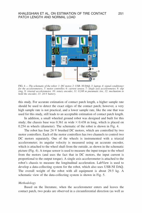
In addition, a small wheeled ground robot was designed and built for thisstudy; the chassis base was 0.361 m wide 3 0.438 m long, which is placed on0.254 m wheels (diameter). The schematic of the robot is shown in Fig. 4.
The robot has four 24-V brushed DC motors, which are controlled by twomotor controllers. Each of the motor controllers has two channels to control twoDC motors separately. One of the wheels is instrumented with a triaxialaccelerometer; its angular velocity is measured using an accurate encoder,which is attached to the wheel shaft from the outside, as shown in the schematicpicture (Fig. 4). A torque sensor is used to measure the input torque to the wheelfrom the motors (and uses the fact that in DC motors, the input current isproportional to the output torque). A single axis accelerometer is attached to therobot’s chassis to measure the longitudinal acceleration. LabView is used todevelop a data-collecting system for the robot, which also uses USB-NI DAQ.The overall weight of the robot with all equipment is about 29.5 kg. Aschematic view of the data-collecting system is shown in Fig. 5.
Methodology
Based on the literature, when the accelerometer enters and leaves thecontact patch, two peaks are observed in a circumferential direction (as well as
FIG. 4 — The schematic of the robot: 1: DC motor, 2: USB- NI DAQ, 3: laptop, 4: signal conditionerfor the accelerometers, 5: motor controller, 6: current sensor, 7: single axis accelerometer, 8: slipring, 9: triaxial accelerometer, 10: rotary encoder, 11: 0.248 m pneumatic tire, 12: mechanism tohold the encoder, 13: 24-V battery.
KHALEGHIAN ET AL. ON ESTIMATION OF TIRE CONTACTPATCH LENGTH AND NORMAL LOAD
251
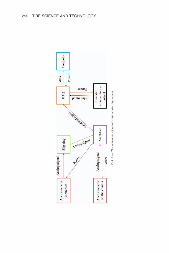
FIG
.5
—T
he
sch
ema
tic
of
rob
ot’
sd
ata
-co
llec
tin
gsy
stem
.
252 TIRE SCIENCE AND TECHNOLOGY

in a radial direction) of acceleration data, which represent the contact patchregion [4,12]. Circumferential and radial components of the accelerometer areshown in Fig. 6 for a sample set of data.
A set of tests with three different normal loads and three differentlongitudinal speeds (shown in Table 1) is used to train a neural network toestimate the normal load using the trailer test setup. Each test has been repeatedin both directions (the first test was performed in one direction and the secondone in the opposite direction) to compensate for the effect of road grade, and theaverage data are used. Fig. 7 shows the algorithm that is used to estimate thenormal load.
A computer code is developed that uses the encoder signal to extract thedata for every tire revolution and detects the acceleration peaks. Once the timeassociated with each peak is detected, it should be multiplied by the trailer
FIG. 6 — Radial and circumferential component of acceleration.
TABLE 1 — Different test conditions.
Trailer speed Normal load (N)
mph km/h
15 24.14 2000 3000 4000
25 40.23 2000 3000 4000
35 56.32 2000 3000 4000
KHALEGHIAN ET AL. ON ESTIMATION OF TIRE CONTACTPATCH LENGTH AND NORMAL LOAD
253
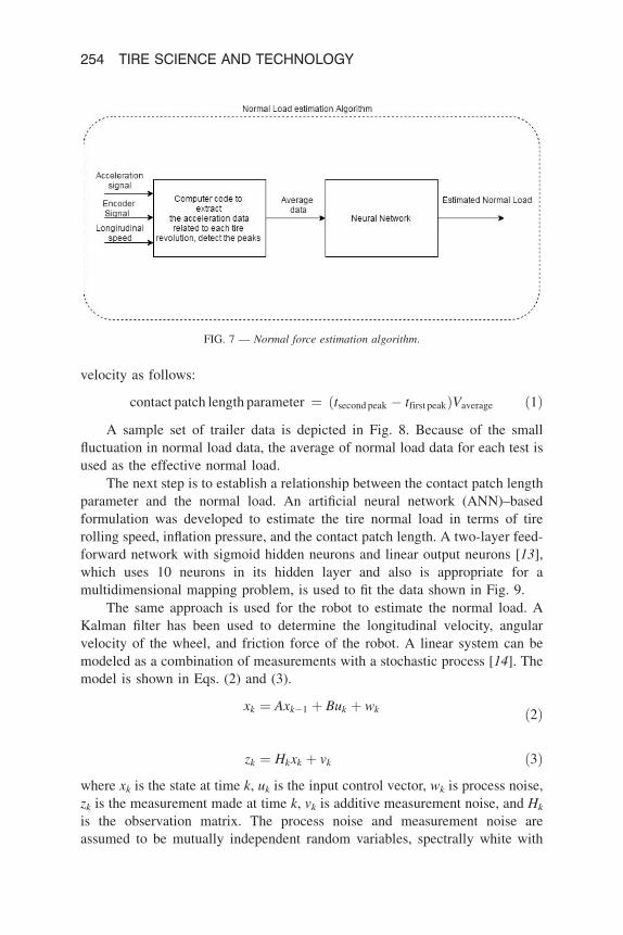
velocity as follows:
contact patch length parameter ¼ ðtsecond peak � tfirst peakÞVaverage ð1Þ
A sample set of trailer data is depicted in Fig. 8. Because of the smallfluctuation in normal load data, the average of normal load data for each test isused as the effective normal load.
The next step is to establish a relationship between the contact patch lengthparameter and the normal load. An artificial neural network (ANN)–basedformulation was developed to estimate the tire normal load in terms of tirerolling speed, inflation pressure, and the contact patch length. A two-layer feed-forward network with sigmoid hidden neurons and linear output neurons [13],which uses 10 neurons in its hidden layer and also is appropriate for amultidimensional mapping problem, is used to fit the data shown in Fig. 9.
The same approach is used for the robot to estimate the normal load. AKalman filter has been used to determine the longitudinal velocity, angularvelocity of the wheel, and friction force of the robot. A linear system can bemodeled as a combination of measurements with a stochastic process [14]. Themodel is shown in Eqs. (2) and (3).
xk ¼ Axk�1 þ Buk þ wk ð2Þ
zk ¼ Hkxk þ vk ð3Þ
where xk is the state at time k, uk is the input control vector, wk is process noise,zk is the measurement made at time k, vk is additive measurement noise, and Hk
is the observation matrix. The process noise and measurement noise areassumed to be mutually independent random variables, spectrally white with
FIG. 7 — Normal force estimation algorithm.
254 TIRE SCIENCE AND TECHNOLOGY

normal probability distributions:
pðwÞ ¼ N ð0;QÞ ð4Þ
pðvÞ ¼ N ð0;RÞ ð5Þ
where process noise covariance Q and measurement noise covariance Rmatrices are assumed to be constant. The Kalman filter estimates the state byminimizing the posteriori estimation error covariance using two stages ofprediction and correction.
predictionbx �k ¼ Abxk�1 þ BukbP �k ¼ AbPk�1AT þ Q
�ð6Þ
FIG. 9 — Two-layer feed-forward network, used to fit measured data.
FIG. 8 — Normal force, longitudinal speed, and encoder signal (raw data).
KHALEGHIAN ET AL. ON ESTIMATION OF TIRE CONTACTPATCH LENGTH AND NORMAL LOAD
255
correctionKk ¼ bP �k HTðH bP2
k HT 1 RÞ2 1bxk ¼ bx �k þ Kkðzk � Hbx �k ÞbPk ¼ ðI � KkHÞ bP �k8<: ð7Þ
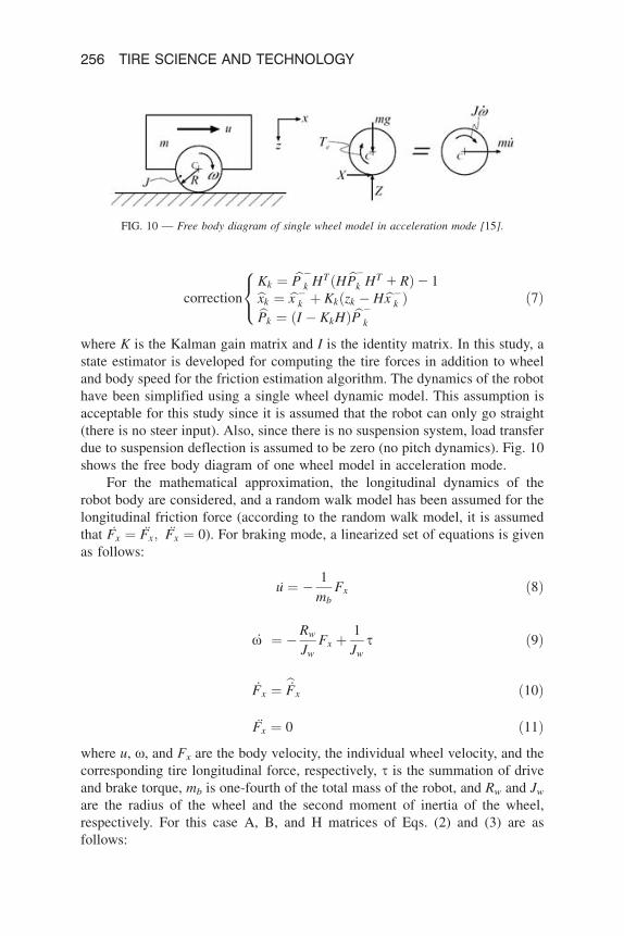
where K is the Kalman gain matrix and I is the identity matrix. In this study, astate estimator is developed for computing the tire forces in addition to wheeland body speed for the friction estimation algorithm. The dynamics of the robothave been simplified using a single wheel dynamic model. This assumption isacceptable for this study since it is assumed that the robot can only go straight(there is no steer input). Also, since there is no suspension system, load transferdue to suspension deflection is assumed to be zero (no pitch dynamics). Fig. 10shows the free body diagram of one wheel model in acceleration mode.
For the mathematical approximation, the longitudinal dynamics of therobot body are considered, and a random walk model has been assumed for thelongitudinal friction force (according to the random walk model, it is assumedthat Fx ¼ Fx; Fx ¼ 0). For braking mode, a linearized set of equations is givenas follows:
u ¼ � 1
mbFx ð8Þ
_x ¼ �Rw
JwFx þ
1
Jws ð9Þ
_Fx ¼ b_Fx ð10Þ
Fx ¼ 0 ð11Þ
where u, x, and Fx are the body velocity, the individual wheel velocity, and thecorresponding tire longitudinal force, respectively, s is the summation of driveand brake torque, mb is one-fourth of the total mass of the robot, and Rw and Jw
are the radius of the wheel and the second moment of inertia of the wheel,respectively. For this case A, B, and H matrices of Eqs. (2) and (3) are asfollows:
FIG. 10 — Free body diagram of single wheel model in acceleration mode [15].
256 TIRE SCIENCE AND TECHNOLOGY

A ¼
0 0 � 1
mb0
0 0 �Rw
Jw0
0 0 0 10 0 0 0
266666664
377777775;B ¼
01Jw
00
266664
377775;H ¼
0 0 � 1
mb0
0 1 0 0
24
35 ð12Þ
Results and Discussion
For the normal load estimation algorithm with the trailer test setup, two setsof data were collected: one set was used to train the neural network usingMATLAB Neural Network Toolbox, and the second data set was used tovalidate the trained neural network. The second set of data was taken withsimilar conditions to training data, but because of uncertainty in running thetests, the validation data points are not exactly equal to those of the trainingdata.
The left graphic in Fig. 11 shows a histogram of the error percentagesbetween estimated and measured normal forces for training data points, whichindicates that the maximum percentage error of the trained data set is less than4%.
The right graphic in Fig. 11 shows the histogram of the error of thevalidation data points. As seen in the figure, the maximum percentage of error isless than 9%. It should be noted that this set of data was not used in the trainingprocess of the neural network and was collected only for validation purpose.
It is normal to see larger error percentages with the validation data setcompared with the training data set. It should be noted that only one data pointof the validation set is close to 9% error, and the rest of the points are
FIG. 11 — Left: Histogram of error percentages for the training data set. Right: Histogram of errorpercentages for the validation data set.
KHALEGHIAN ET AL. ON ESTIMATION OF TIRE CONTACTPATCH LENGTH AND NORMAL LOAD
257

concentrated below 5%. That point could be considered as an outlier. The samesituation holds more or less with the training data set. Usually, one or two pointshave larger error percentages, but they are relatively far from the region wherethe rest of the points are concentrated.
An experiment was designed to validate the proposed estimation algorithmduring a braking maneuver, and the small ground robot was used for thispurpose. The robot starts from rest, and then an angular velocity of 95 rpm(–5rpm) is reached immediately and remains constant for 2 seconds. The brakeis then applied gradually until the robot comes to a complete stop. Themeasured states are the angular velocity of the wheel and the longitudinalacceleration of the chassis. Also, the control signal is the input torque to thewheel from the DC motor, which is measured using the available torque sensor.The outputs of the estimation algorithm are the longitudinal speed, angularvelocity of the wheel, and the friction force.
The estimated and measured wheel speeds and the estimated and measuredlongitudinal robot speeds are presented in Figs. 12 and 13, respectively. Asobserved in the figure, the estimation algorithm works properly, and the measuredand estimated values of wheel speed (which is the radius3 the angular velocity ofthe wheel) and robot longitudinal speed are in good agreement.
According to Fig. 13, the maneuver can be divided into three differentparts: the first part is accelerating, the second part is constant speed, and thethird part is braking. The other output of the estimation algorithm is the frictionforce. Once the wheel speed, longitudinal speed, and the friction force isobtained using the Kalman filter, the friction coefficient and slippage value canbe calculated as follows (the normal load was estimated using the sameapproach as with the intelligent tire):
l ¼ Fx
FNð13Þ
slip ratio ¼ Rwx� V
Vð14Þ
FIG. 12 — Measured and estimated wheel speed.
258 TIRE SCIENCE AND TECHNOLOGY

where FN is the normal force, Rw is the radius of the wheel, and V is the robot’s
longitudinal speed.
The friction coefficient versus slippage values for the braking part is plotted
in Figure 14.
The saturated value of the l-slippage curve is in good agreement with the
real value (rubber-wet asphalt), and the algorithm is validated.
Conclusion
Accurate estimation of tire normal load leads to better estimation of friction
force and better performance of traction and antilock braking system
controllers. In this study, a simple intelligent tire base algorithm is introduced
to estimate the tire normal load. Although the sampling rate was not very high,
it was sufficient to find a parameter related to contact patch length and accurate
estimation of the normal load.
FIG. 13 — Measured and estimated longitudinal robot speed.
FIG. 14 — The friction coefficient for different slip.
KHALEGHIAN ET AL. ON ESTIMATION OF TIRE CONTACTPATCH LENGTH AND NORMAL LOAD
259

A set of tests with different applied normal loads was performed with thetrailer test setup at different speeds, and a two-layer feed-forward networkwith 10 neurons in its hidden layers was developed to fit the processed data.To validate the algorithm, it was tested using another set of measured data,and good agreement was observed between measured and estimated normalloads. The proposed algorithm can be used easily in the vehicle industry toestimate the tire normal load; however, for each size of tire, a separate neuralnetwork should be trained and stored as a black box, which estimates the tireload.
As a practical application for the proposed algorithm, a similar approach isused for a small ground wheeled robot to estimate the normal load (a separateneural network was trained and used for this purpose) along with Kalman filter–based estimation algorithm to estimate the longitudinal velocity of the robot andthe tire-road friction force. Finally, the estimated wheel speed, longitudinalrobot speed, and friction coefficient were compared with the measured values;good agreement was observed, and the estimation algorithm was validated.
References
[1] Yilmazoglu, O., Brandt, M., Sigmund, J., Genc, E., and Hartnagel, H. L., ‘‘Integrated InAs/
GaSb 3D Magnetic Field Sensors for ‘‘the Intelligent Tire’’,’’ Sensors and Actuators A:
Physical, Vol. 94, 2001, pp. 59–63.
[2] Zhang, X., Wang, F., Wang, Z., and He, D., ‘‘Intelligent Tires Based on Wireless Passive
Surface Acoustic Wave Sensors,’’ Proceedings. The 7th International IEEE Conference on
Intelligent Transportation Systems, IEEE, 2004.
[3] Pohl, A., Reinhard S., and Reindl, L., ‘‘The ‘‘intelligent tire’’ Utilizing Passive SAW Sensors
Measurement of Tire Friction,’’ IEEE Transactions on Instrumentation and Measurement,
Vol. 48, 1999, pp. 1041–1046.
[4] Singh, K. B., Arat, M. A., and Taheri, S., ‘‘An Intelligent Tire Based Tire-Road Friction
Estimation Technique and Adaptive Wheel Slip Controller for Antilock Brake System,’’
Journal of Dynamic Systems, Measurement, and Control, Vol. 135, 2013, p. 031002.
[5] Singh, K. B., Arat, M. A., and Taheri, S., ‘‘Development of a Smart Tire System and Its Use in
Improving the Performance of a Collision Mitigation Braking System,’’ ASME International
Mechanical Engineering Congress and Exposition, Houston, TX, 2012, pp. 77–87.
[6] Arat, M. A., Singh, K. B., and Taheri, S., ‘‘An Intelligent Tire Based Adaptive Vehicle Stability
Controller,’’ International Journal of Vehicle Design, Vol. 65, 2014, pp. 118–143.
[7] Ray, L. R., ‘‘Nonlinear Tire Force Estimation and Road Friction Identification: Simulation and
Experiments,’’ Automatica, Vol. 33, 1997, pp. 1819–1833.
[8] Li, L., Wang, F.-Y., and Zhou, Q., ‘‘Integrated Longitudinal and Lateral Tire/Road Friction
Modeling and Monitoring for Vehicle Motion Control,’’ IEEE Transactions on Intelligent
Transportation Systems, Vol. 7, 2006, pp. 1–19.
[9] Ghasemalizadeh, O., Taheri, S., Singh, A., and Goryca, J., ‘‘Semi-active Suspension Control
Using Modern Methodology: Comprehensive Comparison Study,’’ arXiv Preprint arXiv, 2014,
1411.3305.
260 TIRE SCIENCE AND TECHNOLOGY

[10] Taheri, S., Sandu, C., Taheri, S., Pinto, E., and Gorsich, D., ‘‘A Technical Survey on
Terramechanics Models for Tire–Terrain Interaction Used in Modeling and Simulation of
Wheeled Vehicles,’’ Journal of Terramechanics, Vol. 57, 2015, pp. 1–22.
[11] Taheri, S., Sandu, C., and Taheri, S., ‘‘Development and Implementation of a Hybrid Soft Soil
Tire Model (HSSTM),’’ Proceedings of the 18th International Conference of the ISTVS,
Seoul, Korea, 2014.
[12] Matilainen, M. J., and Tuononen, A. J., ‘‘Intelligent Tire to Measure Contact Length in Dry
Asphalt and Wet Concrete Conditions,’’ International Symposium on Advanced Vehicle
Control, Seoul, Korea, 2012.
[13] Duda, R., Hart, P., and Stork, D., Pattern Classification, 2nd ed., John Wiley & Sons, New
York, 2001.
[14] Doumiati, M., Charara, A., Victorino, A., and Lechner, D., Vehicle Dynamics Estimation Using
Kalman Filtering: Experimental Validation, Wiley-ISTE, New York, 2012.
[15] Olson, B. J., Shaw, S. W., and Stepan, G., ‘‘Nonlinear Dynamics of Vehicle Traction,’’ Vehicle
System Dynamics, Vol. 40, 2003, pp. 377–399.
KHALEGHIAN ET AL. ON ESTIMATION OF TIRE CONTACTPATCH LENGTH AND NORMAL LOAD
261


![Tire Price List [TireOutfitters Toronto Tire Specialist]](https://img.pdfslide.us/doc/110x75/542ceaed219acd4e4b8b4d6e/tire-price-list-tireoutfitters-toronto-tire-specialist.jpg)