Embed Size (px)
Citation preview
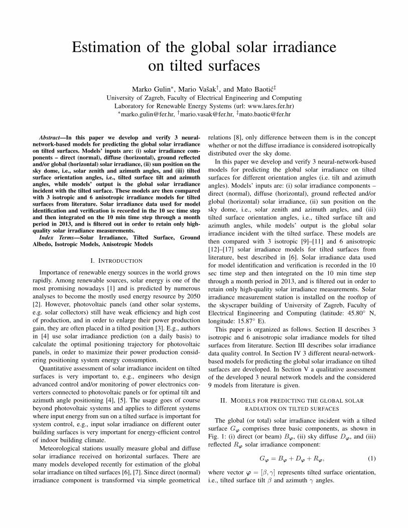
Estimation of the global solar irradianceon tilted surfaces
Marko Gulin∗, Mario Vasak†, and Mato Baotic‡University of Zagreb, Faculty of Electrical Engineering and Computing
Laboratory for Renewable Energy Systems (url: www.lares.fer.hr)∗[email protected], †[email protected], ‡[email protected]
Abstract—In this paper we develop and verify 3 neural-network-based models for predicting the global solar irradianceon tilted surfaces. Models’ inputs are: (i) solar irradiance com-ponents – direct (normal), diffuse (horizontal), ground reflectedand/or global (horizontal) solar irradiance, (ii) sun position on thesky dome, i.e., solar zenith and azimuth angles, and (iii) tiltedsurface orientation angles, i.e., tilted surface tilt and azimuthangles, while models’ output is the global solar irradianceincident with the tilted surface. These models are then comparedwith 3 isotropic and 6 anisotropic irradiance models for tiltedsurfaces from literature. Solar irradiance data used for modelidentification and verification is recorded in the 10 sec time stepand then integrated on the 10 min time step through a monthperiod in 2013, and is filtered out in order to retain only high-quality solar irradiance measurements.
Index Terms—Solar Irradiance, Tilted Surface, GroundAlbedo, Isotropic Models, Anisotropic Models
I. INTRODUCTION
Importance of renewable energy sources in the world growsrapidly. Among renewable sources, solar energy is one of themost promising nowadays [1] and is predicted by numerousanalyses to become the mostly used energy resource by 2050[2]. However, photovoltaic panels (and other solar systems,e.g. solar collectors) still have weak efficiency and high costof production, and in order to enlarge their power productiongain, they are often placed in a tilted position [3]. E.g., authorsin [4] use solar irradiance prediction (on a daily basis) tocalculate the optimal positioning trajectory for photovoltaicpanels, in order to maximize their power production consid-ering positioning system energy consumption.
Quantitative assessment of solar irradiance incident on tiltedsurfaces is very important to, e.g., engineers who designadvanced control and/or monitoring of power electronics con-verters connected to photovoltaic panels or for optimal tilt andazimuth angle positioning [4], [5]. The usage goes of coursebeyond photovoltaic systems and applies to different systemswhere input energy from sun on a tilted surface is important forsystem control, e.g., input solar irradiance on different outerbuilding surfaces is very important for energy-efficient controlof indoor building climate.
Meteorological stations usually measure global and diffusesolar irradiance received on horizontal surfaces. There aremany models developed recently for estimation of the globalsolar irradiance on tilted surfaces [6], [7]. Since direct (normal)irradiance component is transformed via simple geometrical
relations [8], only difference between them is in the conceptwhether or not the diffuse irradiance is considered isotropicallydistributed over the sky dome.
In this paper we develop and verify 3 neural-network-basedmodels for predicting the global solar irradiance on tiltedsurfaces for different orientation angles (i.e. tilt and azimuthangles). Models’ inputs are: (i) solar irradiance components –direct (normal), diffuse (horizontal), ground reflected and/orglobal (horizontal) solar irradiance, (ii) sun position on thesky dome, i.e., solar zenith and azimuth angles, and (iii)tilted surface orientation angles, i.e., tilted surface tilt andazimuth angles, while models’ output is the global solarirradiance incident with the tilted surface. These models arethen compared with 3 isotropic [9]–[11] and 6 anisotropic[12]–[17] solar irradiance models for tilted surfaces fromliterature, best described in [6]. Solar irradiance data usedfor model identification and verification is recorded in the 10sec time step and then integrated on the 10 min time stepthrough a month period in 2013, and is filtered out in order toretain only high-quality solar irradiance measurements. Solarirradiance measurement station is installed on the rooftop ofthe skyscraper building of University of Zagreb, Faculty ofElectrical Engineering and Computing (latitude: 45.80◦ N,longitude: 15.87◦ E).
This paper is organized as follows. Section II describes 3isotropic and 6 anisotropic solar irradiance models for tiltedsurfaces from literature. Section III describes solar irradiancedata quality control. In Section IV 3 different neural-network-based models for predicting the global solar irradiance on tiltedsurfaces are developed. In Section V a qualitative assessmentof the developed 3 neural network models and the considered9 models from literature is given.
II. MODELS FOR PREDICTING THE GLOBAL SOLARRADIATION ON TILTED SURFACES
The global (or total) solar irradiance incident with a tiltedsurface Gϕ comprises three basic components, as shown inFig. 1: (i) direct (or beam) Bϕ, (ii) sky diffuse Dϕ, and (iii)reflected Rϕ solar irradiance component:
Gϕ = Bϕ +Dϕ +Rϕ, (1)
where vector ϕ = [β, γ] represents tilted surface orientation,i.e., tilted surface tilt β and azimuth γ angles.

While measured direct (normal) irradiance is converted todirect irradiance on a tilted surface by simple geometricalrelationship between the two surfaces, this is not the casefor the diffuse component because diffuse irradiance comesfrom all points of the sky except the sun. A relatively largenumber of solar irradiance models for tilted surfaces have beenproposed which include isotropic [9]–[11] and anisotropic[12]–[17] models.
Fig. 1. Solar irradiance components.
A. Direct (tilted) irradiance, BϕCalculation of the direct irradiance incident with a tilted
surface Bϕ is purely geometrical:
Bϕ = Bn cos θ =Bh
cos θzcos θ = Bhrb, (2)
where Bn and Bh are direct (normal) and direct (horizontal)solar irradiance, rb is direct irradiance conversion factor
rb = max(0,cos θ
cos θz), (3)
and θ is the angle of incidence, i.e., the angle between the sundirection and the normal direction of a tilted surface [8]:
cos θ = cos θz cosβ + sin θz sinβ cos(γs − γ), (4)
where θz and γs are the solar zenith and azimuth angles,respectively. Detailed angles description is shown in Fig. 2.
Fig. 2. Zenith angle θz , angle of incidence θ, tilt angle β and azimuth angleγ for a tilted surface [8].
B. Diffuse (tilted) irradiance, DϕStudies [18] have led to a description [6] of the diffuse
component being composed of an isotropic component Dϕ,iso(i.e., uniform irradiance from the sky dome), circumsolarcomponent Dϕ,cs (i.e., resulting from the forward scattering ofsolar irradiance and concentrated in an area close to the sun),and a horizon brightening component Dϕ,hb (i.e., concentratedin a band near the horizon and most pronounced in clear skies):
Dϕ = Dϕ,iso +Dϕ,cs +Dϕ,hb. (5)
There are many models developed recently used to calculatediffuse solar irradiance incident with a tilted surface Dϕ. Maindifference between them is in the concept of whether or notthe diffuse irradiance is isotropically distributed over the skydome. In this paper we will verify 3 isotropic and 6 anisotropicmodels. Each model develops the diffuse transposition factor(i.e., the ratio of diffuse irradiance on a tilted surface to thatof a horizontal, Rd) according to specific assumptions:
Dϕ = DhRd, Rd ≥ 0, (6)
where Dh is the diffuse (horizontal) irradiance.
ISOTROPIC MODELS
Liu-Jordan (LJ). Liu-Jordan model, [9] sets the diffuseirradiance transposition factor as:
Rd =1
2(1 + cosβ). (7)
Korokanis (Ko). The isotropic sky assumption was ques-tioned in [19] where it was found that the sky’s southern part(in northern hemisphere) is responsible for 63% of the totalintensity of diffuse irradiance. Based on this finding, authorsin [10] modified the Liu-Jordan isotropic model as follows:
Rd =1
3(2 + cosβ), (8)
for which a vertical plane oriented southwards covers 66.7%of the total sky irradiance.
Badescu (Ba). Pseudo-isotropic model proposed by authorsin [11] define diffuse irradiance transposition factor as:
Rd =1
4(3 + cos 2β). (9)
ANISOTROPIC MODELS
Willmot (Wi). Authors in [12] define diffuse irradiancetransposition factor as:
Rd = rbBn
S0+ Cϕ
S0 −Bn
S0, (10)
where S0 is the solar constant (i.e., 1367 Wm−2), and Cϕ isanisotropic reduction factor defined as:
Cϕ = 1.0115− 0.20293β − 0.080823β2, (11)
where the tilted surface tilt angle β is in radians.

Bugler (Bu). Authors in [13] modified the isotropic modeldefined in (7) by adding terms for the diffuse irradiancecoming from the sun’s disc and for the irradiance from therest of the sky that depends on the angular height of the sunover the horizon:
Rd = Rd,LJ + 0.05BϕDh
(cos θ − Rd,LJ
cos θz
), (12)
where Rd,LJ is the Liu-Jordan isotropic model diffuse irradi-ance transposition factor defined in (7).
Hay (Ha). In the Hay model [14], diffuse irradiance fromthe sky is composed of an isotropic component and a circum-solar one. Horizon brightening is not taken into account. Ananisotropy index, FHay , is used to quantify a portion of thediffuse irradiance treated as circumsolar with the remainingportion of diffuse irradiance assumed to be isotropic:
Rd = FHayrb + (1− FHay)Rd,LJ, FHay =Bn
Gext, (13)
where FHay is the Hay’s sky-clarity factor, and Gext is theextra-atmospheric solar radiation. To simplify the model, onecan use an approximation Gext = S0. The Hay model isreduced to the Liu-Jordan model (7) for FHay = 0.
Skartveit-Olseth (SO). Solar irradiance measurements in-dicate that a significant part of sky diffuse irradiance underovercast sky conditions comes from the sky region aroundthe zenith. This effect vanishes when cloud cover disappears.Skartveit-Olseth [15] modified the Hay model in order toaccount for this effect:
Rd = FHayrb + Z cosβ + (1− FHay − Z)Rd,LJ, (14)
where Z is the Skartveit-Olseth’s correction factor defined as:
Z = max(0, 0.3− 2FHay). (15)
Note that for FHay ≥ 0.15, the Skartveit-Oleth’s modelreduces to the Hay’s model.
Temps-Coulson (TC). Assuming clear sky conditions,Temps-Coulson [16] modified the Liu-Jordan isotropic model(7) by introducing two terms, P1 and P2, as follows:
Rd = Rd,LJP1P2, (16)
where term P1 evaluate the diffuse irradiance coming from thevicinity of the solar disc, and term P2 evaluate sky irradiancefrom the region close to the horizon:
P1 = 1 + cos2 θ sin3 θz, (17a)
P2 = 1 + sin3β
2. (17b)
Klucher model (Kl). Klucher [17] found that the isotropicmodel (7) gave good results for overcast skies but underesti-mates irradiance under clear and partly cloudy sky conditions,characterized by an increased intensity near the horizon and
near the circumsolar sky region. To overcome such a lim-itation, he proposed to refine Temps-Coulson model (16) byintroducing a factor fK determining the degree of cloud cover:
Rd = Rd,LJ(1 + fK cos2 θ sin3 θz
)(1 + fK sin3
β
2
), (18)
where fK is the Kluchers’ conversion factor defined as:
fK = 1−(Dh
Gh
)2, (19)
where Gh is global (horizontal) solar irradiance defined as:
Gh = Bn cos θz +Dh. (20)
Note that for fK = 0 (i.e. during the clear sky conditions) andfK = 1 (i.e. during the overcast conditions), Klucher’s modelreduces to the Liu-Jordan model and the Temps-Coulsonmodel, respectively.
C. Reflected (tilted) irradiance, Rϕ
The classical approach to the modelling of the reflected irra-diance assumes that reflected rays are diffuse and coefficientsof reflection of the direct and diffuse rays are identical. Theevaluation of the ground reflected diffuse irradiance Rϕ is thusdependent on the transposition factor for ground reflection Rh:
Rϕ = ρGhRh, (21)
where ρ is the foreground’s albedo. Most studies assume [6]that a constant irradiance originates from every point of theground, i.e. the ground reflection process is ideally isotropic.In this case, transposition factor for ground reflection can besimplified into:
Rh =1
2(1− cosβ). (22)
III. IRRADIANCE DATA QUALITY CONTROL
The presented analysis is based upon measurementsrecorded at the rooftop of the skyscraper building of Universityof Zagreb, Faculty of Electrical Engineering and Computing(latitude: 45.80◦ N, longitude: 15.97◦ E). Eight data sets havebeen collected through a month period in 2013: (i-iv) direct(normal) Bn, diffuse (horizontal) Dh, ground reflected Rg ,and global (horizontal) Gh solar irradiance, and (v-viii) globalsolar irradiance incident with a south-oriented tilted surfaceGϕ at following tilt angles β: 5◦, 30◦, 55◦, and 80◦. Theirradiance measurements are recorded with a time step of 10sec and then integrated on a 10 min time step.
The direct (normal) irradiance is measured with a first classCHP 1 sun tracker pyrheliometer with additional sun sensor forclosed-loop sun tracking, while the diffuse (horizontal), groundreflected, and global (horizontal) irradiance are measured withCMP 11 – secondary standard pyranometers. Global solarirradiance incident with a tilted surface is measured with CMP6 pyranometers. For the diffuse measurements, a shading ballis mounted in front of the pyranometer with same solid angleas the pyrheliometer blocking out the direct component.

Fig. 3. SOLYS2 sun tracker with solar irradiance measurement equipmentand sun tracker for closed-loop sun tracking
In order to retain only high-quality irradiance measurementfor identification and verification, irradiance data are filteredout with the following criteria:
0.95Gh,meas ≤ Gh,est ≤ 1.05Gh,meas, (23)
where Gh,meas and Gh,est are measured and estimated (20)global (horizontal) solar irradiance. Approximately 98.9% ofsolar irradiance data samples recorded meet condition (23)(considering only sunshine hours, i.e., θz < 90◦).
IV. DEVELOPMENT OF THE NEURALNETWORK MODEL
Used neural network structure is MultiLayer Perceptron(MLP) neural network [20], [21] with one hidden and outputlayer. Neural network is a mathematical function with anumber of parameters that are fitted in a way so that differencebetween target yt and neural network output yMLP is minimizedfor the given set of input-target pairs for training. Cost-function used for neural network training (parameters tuningby cost-function minimization) is Mean Square Error (MSE):
MSE =1
N
N∑s=1
e2s, es = yt,s − fMLP(Xs,θ), (24)
where N is number of input-target measurement pairs, e isneural network model error, (Xs, yt,s) is s-th input-target pair,fMLP(·, ·) is mathematical function that describes used MLPneural network, and θ is vector of neural network parameters.
Fig. 4. MLP neural network structure with tansig function in hidden layer
Neural network models inputs are: (i-iv) solar irradiancecomponents – direct (normal), diffuse (horizontal), groundreflected and/or global (horizontal) solar irradiance, (v-vi)sun position on the sky dome, i.e., solar zenith and azimuthangles, and (vii-viii) tilted surface orientation angles, i.e., tiltedsurface tilt and azimuth angles, while models’ output is theglobal solar irradiance incident with the tilted surface. Threedifferent neural network models are considered, denoted as:(i) full-input (MLP-F), (ii) full-input hybrid (MLP-H), and(iii) reduced-input (MLP-R) neural network. Full-input neuralnetworks do not use global (horizontal) solar irradiance dataas inputs, while reduced-input neural network does not usedirect (normal) and ground reflected solar irradiance sincethose components are most likely not available by meteoro-logical service. Hybrid neural network additionally takes intoaccount transformation of direct (normal) to direct (tilted) solarirradiance, so that target vector of hybrid neural network is:
yt,MLP-H = Gδ −Bδ, (25)
where Gδ is measured global solar irradiance incident with atilted surface, and Bδ is transformed direct (normal) to direct(tilted) solar irradiance (see Eq. (2)) at orientation angle δ.In this way, hybrid neural network model practically iden-tifies transformation of only diffuse (horizontal) and groundreflected solar irradiance components.
There are several properties that need to be defined bythe user before neural network training can begin. Thoseare primarily: (i) neural network training method, (ii) neuralnetwork training stop criteria to prevent overfitting, and (iii)neural network complexity (determined by number of hiddenlayers, and by number of neurons, i.e., nonlinear activationfunctions in each hidden layer).
Neural network training refers to parameters tuning consid-ering some cost-function. Training will continue until stoppingcriteria are satisfied (e.g., maximum number of iterationsand/or elapsed time). However, to prevent overfitting whereinneural network can learn even noise, aforementioned stoppingcriteria are not enough. To prevent overfitting, data set isdivided on training and validation data sets, with shares of70% and 30% of whole data set, respectively. Neural networkparameters tuning is done considering only training data set,but cost-function is also calculated for validation data set.When cost-function (considering only validation data set)shows no improvement through some predefined number ofiterations (e.g., 10 iterations), training is stopped and bestperforming parameters vector considering validation data setis used. For neural network training (i.e. parameters tuning),a gradient-based Levenberg-Marquardt algorithm is used.
One must have in mind that too simple neural network(small number of neurons) might not be able to perform well,while too complex network (large number of neurons) canbe too demanding for training algorithm. Also, complexityof neural network increases exponentially with number ofhidden layers. In most fitting practical problems, one hiddenlayer with 15-20 neurons is enough for neural network toperform well. Neural network training procedure (for each of

the considered 3 neural network models) is done with differentnumbers of neurons (8 different sizes uniformly distributedfrom 5 to 40 neurons), and is repeated 100 times for eachmode, which gives 3×8×100=2400 neural network trainingsin total. Mean, worst and best cost-function value through 100trainings (on validation data set) for each model and hiddenlayer size is shown in Fig. 24. It is shown that optimal hiddenlayer size is 15–20 neurons, and that with increasing numberof neurons, neural network performance can be even worse.It is also shown that for small number of neurons, hybridmodel shows far best performance compared to other twoneural network models. This is in line with expectation, sincehybrid model does not have to learn transformation of direct(normal) to direct (tilted) irradiance.
100
200
300
400
500
600
MSE
(mea
n)
100
400
700
1000
1300
1600
MSE
(wor
st)
0 5 10 15 20 25 30 35 40 45100
130
160
190
220
250
Neural network hidden layer size
MSE
(bes
t)
Full−inputFull−input (hybrid)Reduced−input
Fig. 5. Mean, worst and best cost-function value in W2/m4 through 100trainings for 3 different models and 8 different hidden layer sizes.
V. QUALITATIVE ASSESMENT OF THE DEVELOPED 3 ANDTHE CONSIDERED 9 MODELS
Performance measures used for models verification areMean Bias Error (MBE), Mean Square Error (MSE), and RootMean Square Error (RMSE), defined as:
MBE =1
N
N∑s=1
es, RMSE =
√√√√ 1
N
N∑s=1
e2s. (26)
Besides MBE, MSE and RMSE, a linear regression R (i.e.correlation coefficient) is also used to test models’ perfor-mance. Table I shows performance indicators, and Fig. 6shows regression plots of developed 3 best performing neural
network models and considered 9 models. Verification ofdeveloped neural network models is done only on validationdata set, while verification of considered 9 models is doneon whole data set. It is shown that developed neural networkmodels significantly outperform considered 9 models by allperformance indicators. However, downside of this approachis that neural network models are applicable only for themeasurement test site.
Similar performance results for considered 9 models shownin Table I are also given in [6]. Nevertheless, we obtainedsomewhat better performance indicators, mainly because ofmore quality measurements of solar irradiance componentsand fewer measurement days considered in the data set. De-veloped neural network models will help us make a new non-site-specific model once a more larger measurement days dataset is collected, as they showed that there exists a nonlinearitythat considered 9 models did not take into account.
TABLE IPERFORMANCE INDICATORS OF CONSIDERED MODELS
MBE MSE RMSE R(W/m2) (W2/m4) (W/m2)
MLP-F 0.09 122.64 11.07 0.99932MLP-H −0.43 121.06 11.00 0.99933MLP-R 0.49 124.32 11.15 0.99931LJ 4.71 436.03 20.88 0.99817Ko −4.84 619.55 24.89 0.99706Ba 15.17 798.56 28.26 0.99760Wi 8.86 503.85 22.45 0.99782Bu 10.09 578.12 24.04 0.99804Ha 4.26 393.23 19.83 0.99812SO 6.85 428.92 20.71 0.99802TC −17.82 977.66 31.27 0.99648Kl −9.32 531.90 23.06 0.99763
VI. CONCLUSION
In this paper we developed and verified 3 different neuralnetwork models for prediction of solar irradiance incident witha tilted surface. Performance of the developed neural networkmodels is compared to performance of most competitive 3isotropic and 6 anisotropic models for tilted surface fromliterature. It is shown that neural network models significantlyoutperform the considered 9 models. However, downside ofthis approach is that developed models are applicable only forthe measurement test site. Developed neural network modelswill help us make a new non-site-specific model once a morelarger measurement days data set is collected.
ACKNOWLEDGMENT
This work has been financially supported by the EuropeanUnion through project ENHEMS-Buildings – Enhancement ofResearch, Development and Technology Transfer Capacities inEnergy Management Systems for Buildings under grant No.IPA2007/HR/16IPO/001-040510, and by the Croatian ScienceFoundation under grant No. I-4463-2011 (MICROGRID). Thissupport is gratefully acknowledged.

Fig. 6. Regression plots of 3 developed neural network models and considered 3 isotropic and 6 anisotropic models for predicting global solar irradiance ontilted surfaces. Horizontal axis shows measured solar irradiance (W/m2), while vertical axis shows estimated solar irradiance (W/m2) on tilted surface.
REFERENCES
[1] J. L. Sawin, “Renewables 2013: Global Status Report,” REN21 Secre-tariat, 2013.
[2] “World in Transition: A Social Contract for Sustainability,” GermanAdvisory Council on Global Change, 2011.
[3] J. Kaldellis, K. Kavadias, and D. Zafirakis, “Experimental validationof the optimum photovoltaic panels’ tilt angle for remote consumers,”Renewable Energy, vol. 46, no. 0, pp. 179–191, October 2012.
[4] M. Gulin, M. Vasak, and N. Peric, “Dynamical optimal positioning of aphotovoltaic panel in all weather conditions,” Applied Energy, vol. 108,no. 0, pp. 429–438, August 2013.
[5] E. D. Mehleri, P. L. Zervas, H. Sarimveis, J. A. Palyvos, and N. C.Markatos, “Determination of the optimal tilt angle and orientation forsolar photovoltaic arrays,” Renewable Energy, vol. 35, no. 11, pp. 2468–2475, November 2010.
[6] C. Demain, M. Journee, and C. Bertrand, “Evaluation of different modelsto estimate the global solar radiation on inclined surfaces,” RenewableEnergy, vol. 50, no. 0, pp. 710–721, February 2013.
[7] M. David, P. Lauret, and J. Boland, “Evaluating tilted plane models forsolar radiation using comprehensive testing procedures, at a southernhemisphere location,” Renewable Energy, vol. 51, no. 0, pp. 124–131,March 2013.
[8] J. Twidell and T. Weir, Renewable Energy Resources, 2nd ed. Taylor& Francis, 2005.
[9] B. Y. H. Liu and R. C. Jordan, “Daily insolation on surfaces tiltedtowards the equator,” ASHRAE Journal, vol. 3, no. 0, pp. 53–59, 1961.
[10] P. S. Koronakis, “On the choice of the angle of tilt for south facing solarcollectors in the athens basin area,” Solar Energy, vol. 36, no. 3, pp.217–225, 1986.
[11] V. Badescu, “3D isotropic approximation for solar diffuse irradiance ontilted surfaces,” Renewable Energy, vol. 26, no. 2, pp. 221–233, June2002.
[12] C. J. Willmott, “On the climatic optimization of the tilt and azimuth offlat-plate solar collectors,” Solar Energy, vol. 28, no. 3, pp. 205–216,1982.
[13] J. W. Bugler, “The determination of hourly insolation on an inclinedplane using a diffuse irradiance model based on hourly measured globalhorizontal insolation,” Solar Energy, vol. 19, no. 5, pp. 477–491, 1977.
[14] J. E. Hay, “Calculation of monthly mean solar radiation for horizontaland inclined surfaces,” Solar Energy, vol. 23, no. 4, pp. 301–307, 1979.
[15] A. Skartveit and J. A. Olseth, “Modelling slope irradiance at highlatitudes,” Solar Energy, vol. 36, no. 4, pp. 333–344, 1986.
[16] R. C. Temps and K. L. Coulson, “Solar radiation incident upon slopes ofdifferent orientations,” Solar Energy, vol. 19, no. 2, pp. 179–184, 1977.
[17] T. M. Klucher, “Evaluation of models to predict insolation on tiltedsurfaces,” Solar Energy, vol. 23, no. 2, pp. 111–114, 1979.
[18] R. Perez, R. Stewart, C. Arbogast, R. Seals, and J. Scott, “An anisotropichourly diffuse radiation model for sloping surfaces: Description, perfor-mance validation, site dependency evaluation,” Solar Energy, vol. 36,no. 6, pp. 481–497, 1986.
[19] H. L. Hamilton and A. Jackson, “A shield for obtaining diffuse skyradiation from portions of the sky,” Solar Energy, vol. 34, no. 1, pp.121–123, 1985.
[20] S. Haykin, Ed., Kalman Filtering and Neural Networks, 1st ed. Wiley-Interscience, 2001.
[21] M. S. Grewal and A. P. Andrews, Kalman Filtering: Theory and PracticeUsing MATLAB, 3rd ed. Wiley-IEEE Press, 2008.