Embed Size (px)
Citation preview
Estimation of the Earth’s Estimation of the Earth’s Impulse Response: Impulse Response:
DeconvolutionDeconvolution and Beyondand BeyondGary Gary PavlisPavlis
Indiana UniversityIndiana UniversityRick AsterRick Aster
New Mexico TechNew Mexico Tech
Presentation for Imaging Science WorkshopWashington University, November 1, 2006
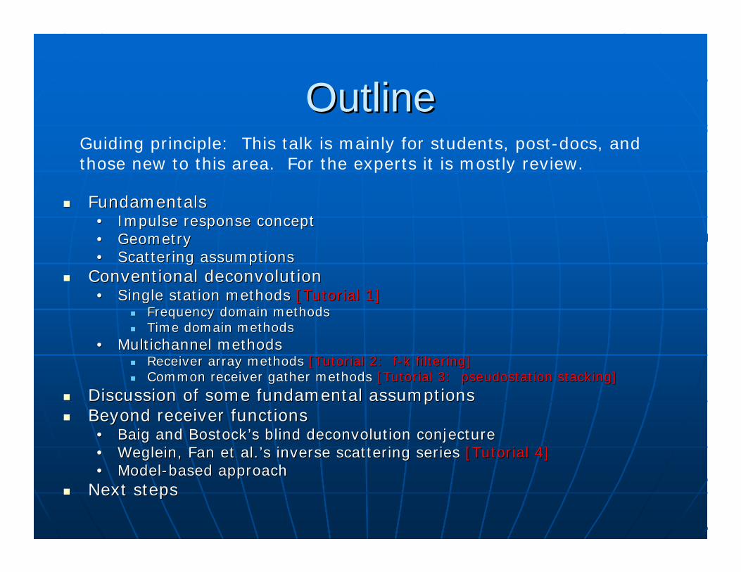
OutlineOutline
FundamentalsFundamentals•• Impulse response conceptImpulse response concept•• GeometryGeometry•• Scattering assumptionsScattering assumptions
Conventional Conventional deconvolutiondeconvolution•• Single station methods Single station methods [Tutorial 1][Tutorial 1]
Frequency domain methodsFrequency domain methodsTime domain methodsTime domain methods
•• MultichannelMultichannel methodsmethodsReceiver array methods Receiver array methods [Tutorial 2: [Tutorial 2: ff--kk filtering]filtering]Common receiver gather methods Common receiver gather methods [Tutorial 3: [Tutorial 3: pseudostationpseudostation stacking]stacking]
Discussion of some fundamental assumptionsDiscussion of some fundamental assumptionsBeyond receiver functionsBeyond receiver functions•• BaigBaig and and Bostock’sBostock’s blind blind deconvolutiondeconvolution conjectureconjecture•• WegleinWeglein, Fan et al.’s inverse scattering series , Fan et al.’s inverse scattering series [Tutorial 4][Tutorial 4]•• ModelModel--based approachbased approach
Next stepsNext steps
Guiding principle: This talk is mainly for students, post-docs, and those new to this area. For the experts it is mostly review.
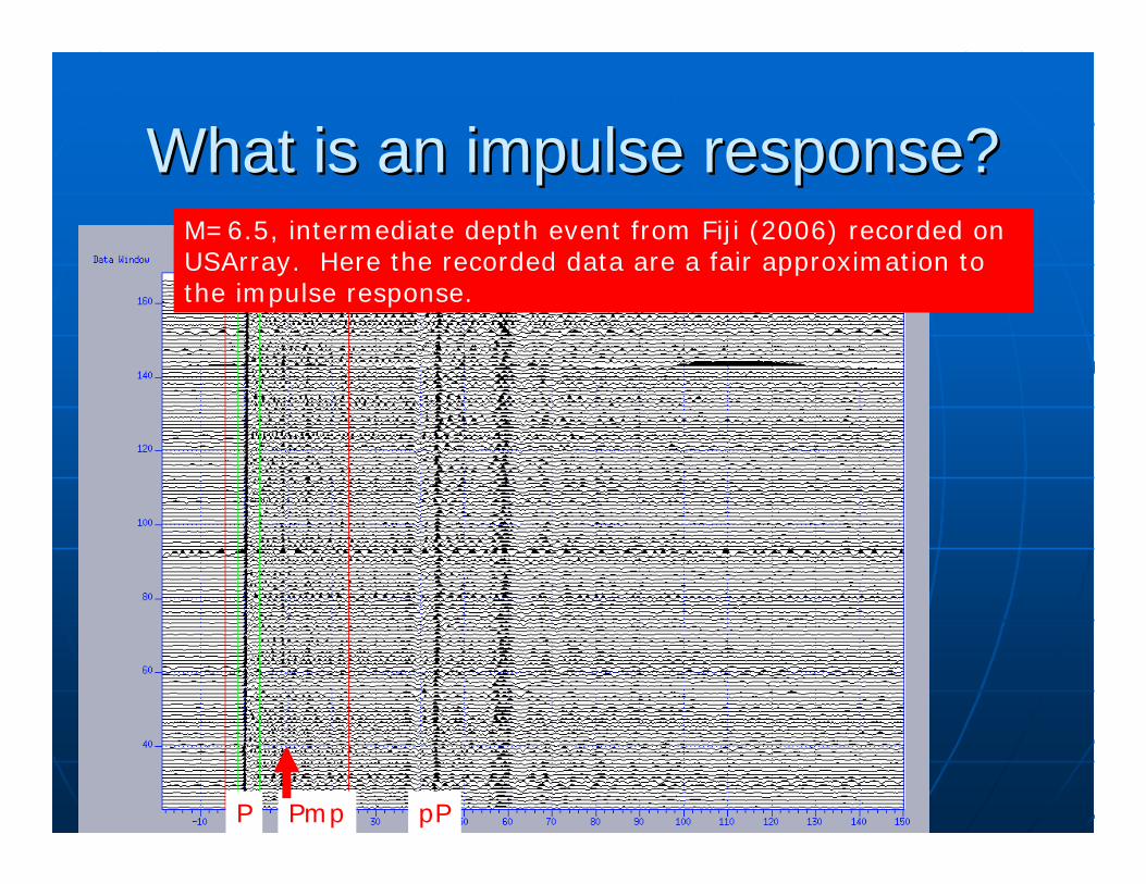
What is an impulse response?What is an impulse response?M=8 event Tonga, 2006, recorded on USArrayM=6.5, intermediate depth event from Fiji (2006) recorded on USArray. Here the recorded data are a fair approximation to the impulse response.
P pPPmp
Why is the impulse response Why is the impulse response fundamental to wavefield imaging?fundamental to wavefield imaging?
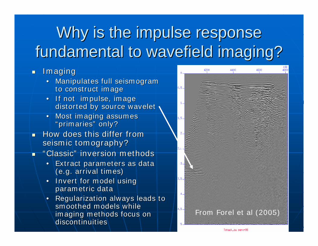
ImagingImaging•• Manipulates full seismogram Manipulates full seismogram
to construct imageto construct image•• If not impulse, image If not impulse, image
distorted by source waveletdistorted by source wavelet•• Most imaging assumes Most imaging assumes
“primaries” only?“primaries” only?How does this differ from How does this differ from seismic tomography?seismic tomography?“Classic” inversion methods“Classic” inversion methods•• Extract parameters as data Extract parameters as data
(e.g. arrival times)(e.g. arrival times)•• Invert for model using Invert for model using
parametric dataparametric data•• Regularization always leads to Regularization always leads to
smoothed models while smoothed models while imaging methods focus on imaging methods focus on discontinuitiesdiscontinuities
From Forel et al (2005)
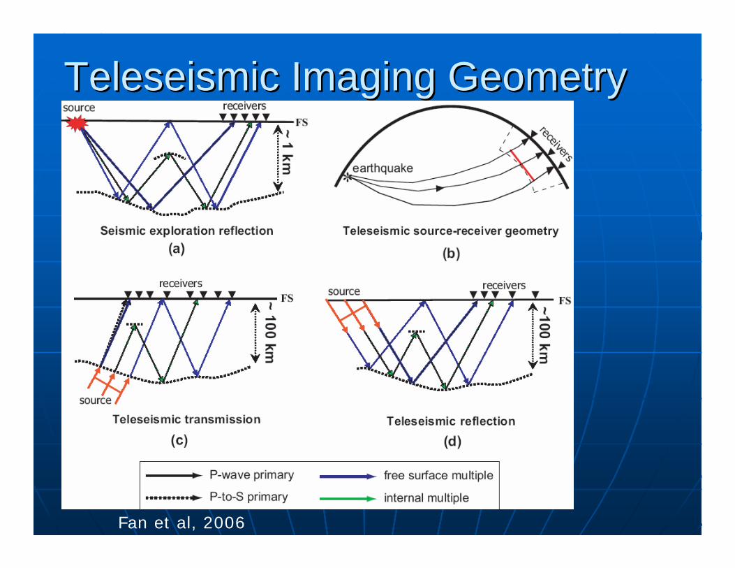
Teleseismic Imaging Geometry Teleseismic Imaging Geometry
Fan et al, 2006
Impedance Contrast
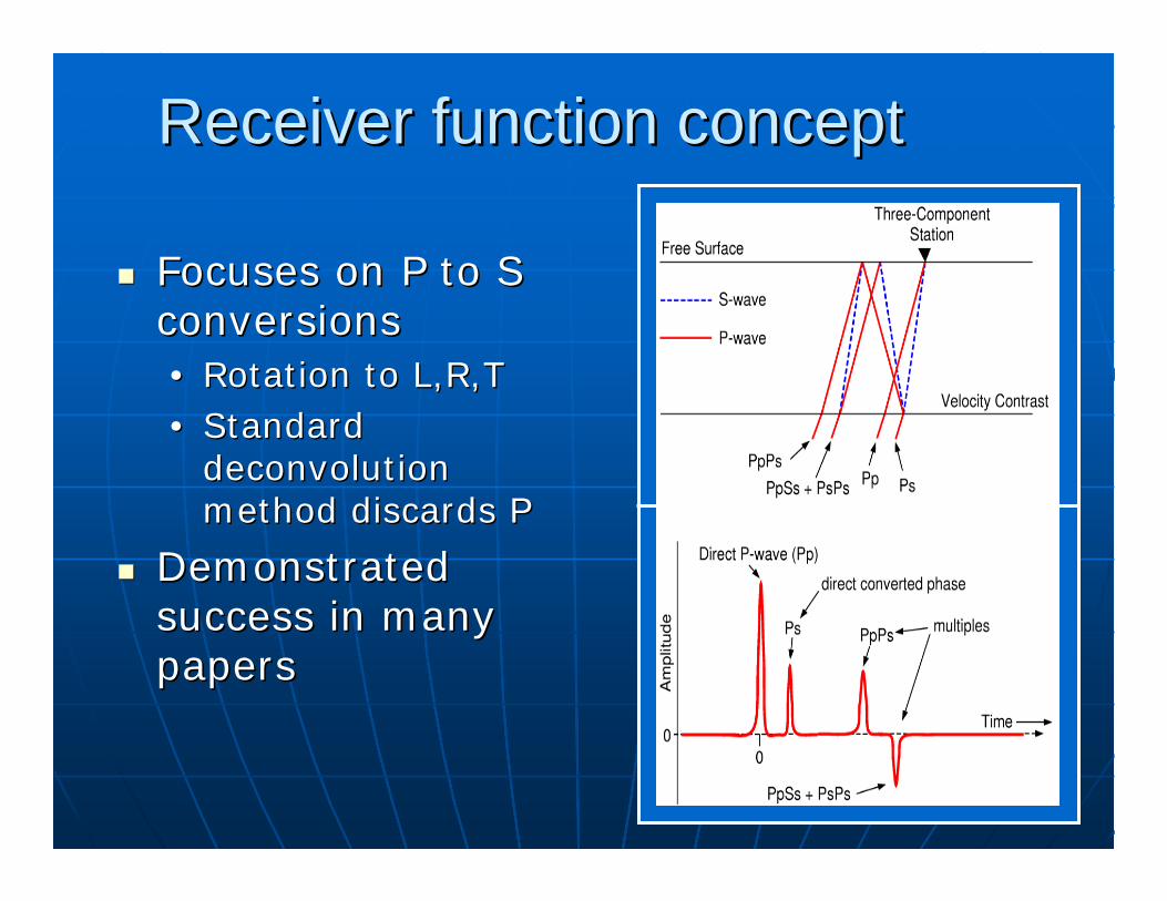
Receiver function conceptReceiver function concept
Focuses on P to S Focuses on P to S conversionsconversions•• Rotation to L,R,TRotation to L,R,T•• Standard Standard
deconvolutiondeconvolutionmethod discards Pmethod discards P
Demonstrated Demonstrated success in many success in many paperspapers
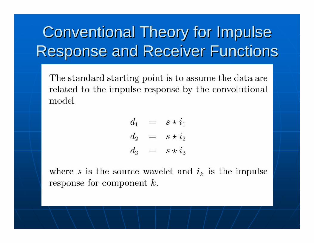
Conventional Theory for Impulse Conventional Theory for Impulse Response and Receiver FunctionsResponse and Receiver Functions
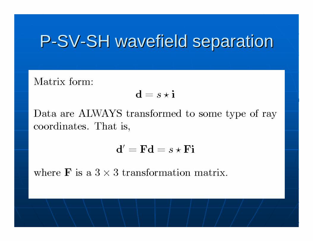
PP--SVSV--SH wavefield separationSH wavefield separation
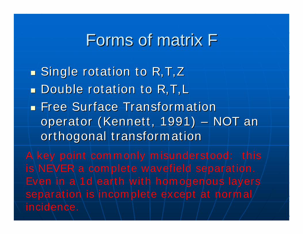
Forms of matrix FForms of matrix F
Single rotation to R,T,ZSingle rotation to R,T,ZDouble rotation to R,T,LDouble rotation to R,T,LFree Surface Transformation Free Surface Transformation operator (Kennett, 1991) operator (Kennett, 1991) –– NOT an NOT an orthogonal transformationorthogonal transformation
A key point commonly misunderstood: this is NEVER a complete wavefield separation. Even in a 1d earth with homogenous layers separation is incomplete except at normal incidence.
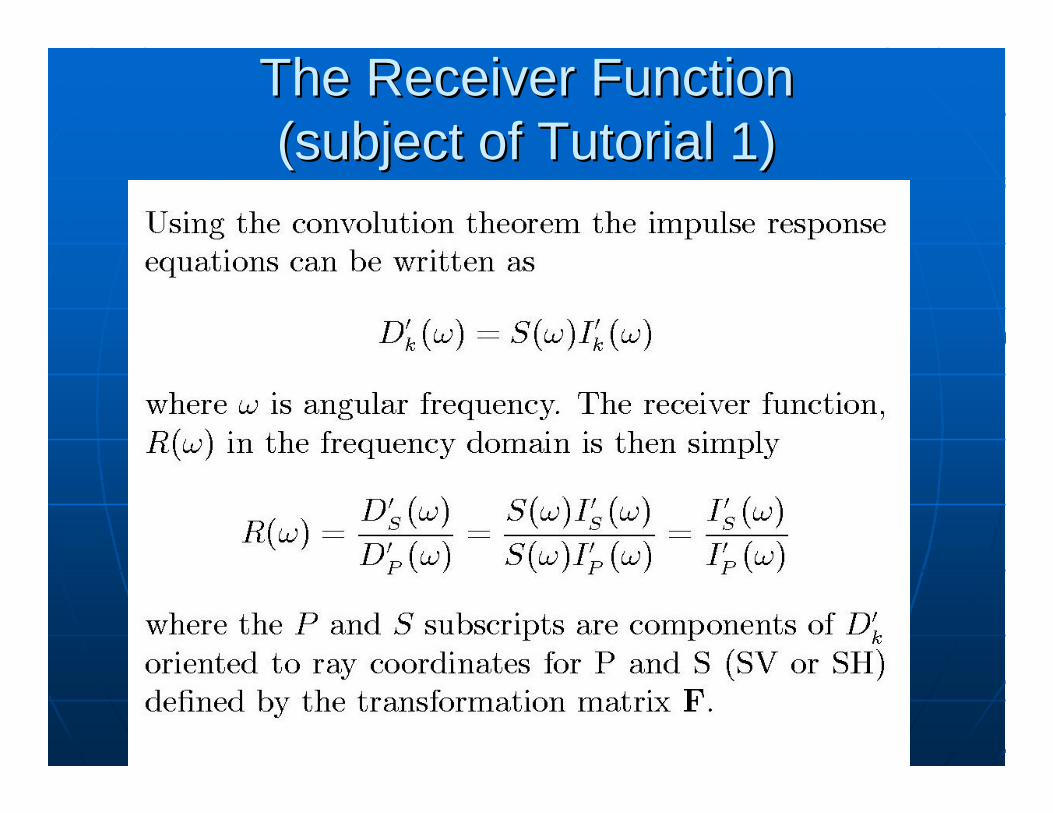
The Receiver FunctionThe Receiver Function(subject of Tutorial 1)(subject of Tutorial 1)
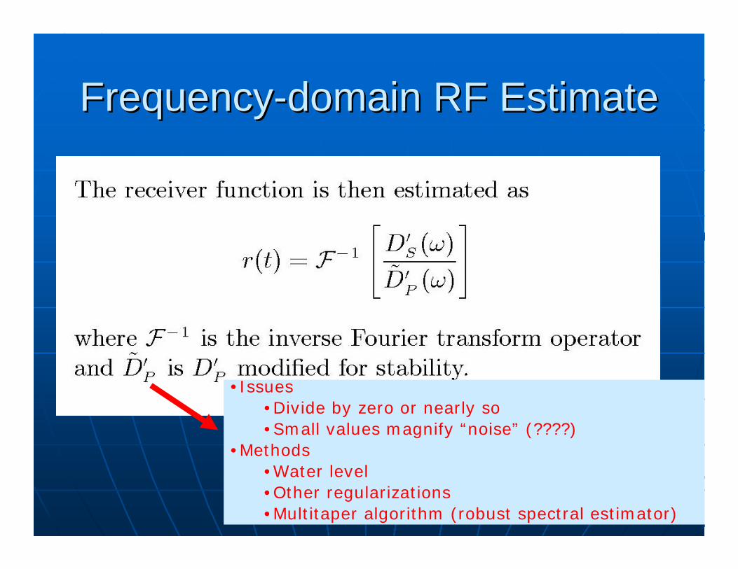
FrequencyFrequency--domain RF Estimatedomain RF Estimate
•Issues•Divide by zero or nearly so•Small values magnify “noise” (????)
•Methods•Water level•Other regularizations•Multitaper algorithm (robust spectral estimator)
Time Domain MethodsTime Domain MethodsCast problem as linear equations d=Cast problem as linear equations d=SiSiSome have preferred this approach to Some have preferred this approach to frequency domain methods because:frequency domain methods because:•• Full machinery of linear inverse theory Full machinery of linear inverse theory
availableavailable•• More flexibility in regularization (e.g. More flexibility in regularization (e.g. TikhonovTikhonov
regularization)regularization)
Very high computational cost compared Very high computational cost compared to frequency domain methodsto frequency domain methodsFor this workshop provide useful insight For this workshop provide useful insight and familiar framework for someand familiar framework for some
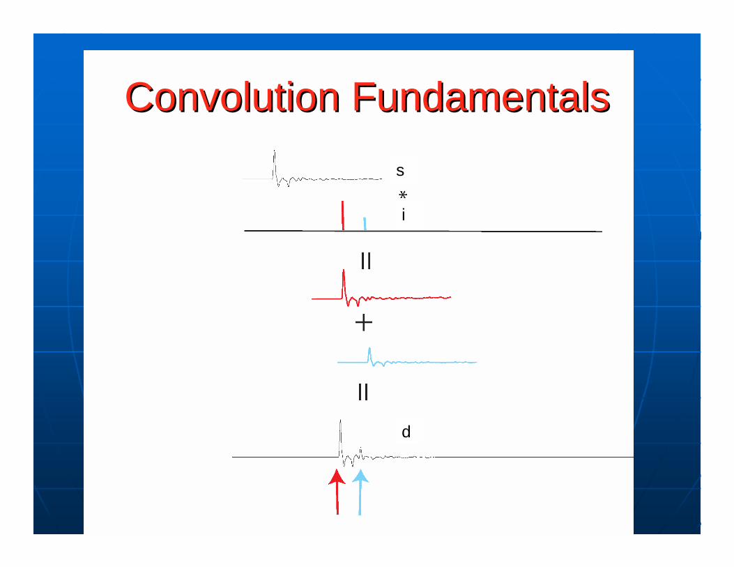
Convolution FundamentalsConvolution Fundamentalss
i
d
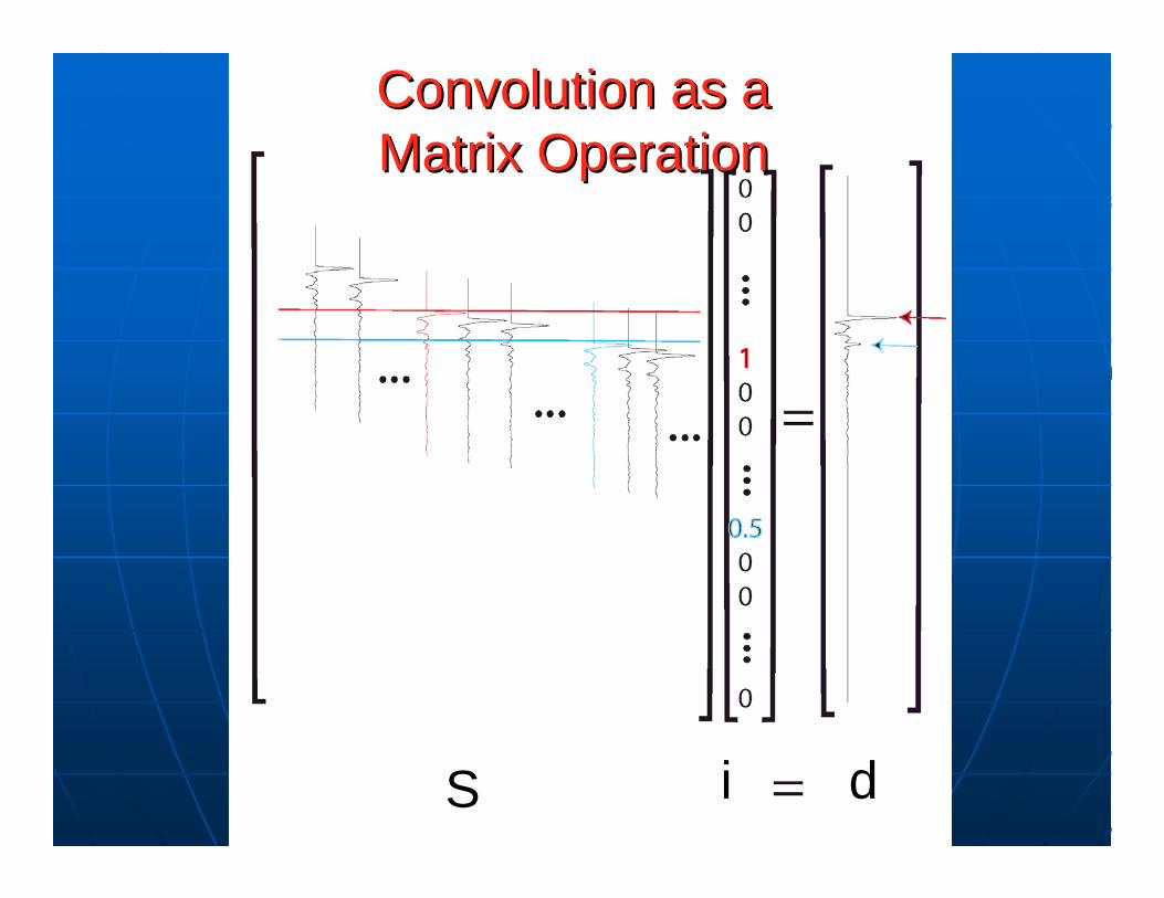
Convolution as a Convolution as a Matrix OperationMatrix Operation
S i d
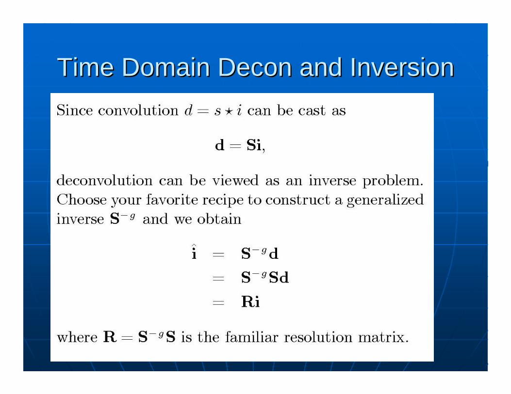
Time Domain Time Domain DeconDecon and Inversionand Inversion
Time or Frequency Domain?Time or Frequency Domain?
Frequency domain method MUCH Frequency domain method MUCH faster to compute (faster to compute (NlogNNlogN versus Nversus N33
algorithm)algorithm)MultitaperMultitaper method (Park and Levin, method (Park and Levin, 2000) is probably the best FD 2000) is probably the best FD methodmethodTime domain approach likely has Time domain approach likely has more unexplored optionsmore unexplored options
Some Fundamental Receiver Some Fundamental Receiver Function AssumptionsFunction Assumptions
Incident wavefield is a pure P waveIncident wavefield is a pure P wave•• Requires very weak scattering in lower mantle to be Requires very weak scattering in lower mantle to be
true; otherwise incident wavefield would not be pure P true; otherwise incident wavefield would not be pure P waves.waves.
•• S wave receiver functions require a comparable S wave receiver functions require a comparable assumptionassumption
Single phase incident as a plane waveSingle phase incident as a plane wave•• Reason for focus on 30Reason for focus on 30--90 degree distance90 degree distance
What happens between 10What happens between 10--30 degrees?30 degrees?What happens beyond 90?What happens beyond 90?
•• Limits time window for some intermediate depth eventsLimits time window for some intermediate depth events•• Limits time window in 90+ range where Limits time window in 90+ range where PcPPcP--P smallP small
Scattering in imaging volume is weakScattering in imaging volume is weak•• More on this one later.More on this one later.
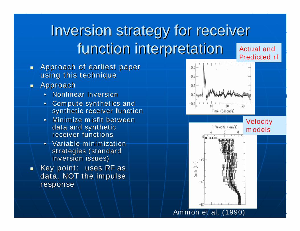
Inversion strategy for receiver Inversion strategy for receiver function interpretationfunction interpretation
Approach of earliest paper Approach of earliest paper using this techniqueusing this techniqueApproachApproach•• Nonlinear inversionNonlinear inversion•• Compute synthetics and Compute synthetics and
synthetic receiver functionsynthetic receiver function•• Minimize misfit between Minimize misfit between
data and synthetic data and synthetic receiver functionsreceiver functions
•• Variable minimization Variable minimization strategies (standard strategies (standard inversion issues)inversion issues)
Key point: uses RF as Key point: uses RF as data, NOT the impulse data, NOT the impulse responseresponse
Actual andPredicted rf
Velocity models
Ammon et al. (1990)
Receiver Functions and Direct Receiver Functions and Direct ImagingImaging
Harder problem than inversion Harder problem than inversion approach becauseapproach because•• Multiples are a BIG problem that is not Multiples are a BIG problem that is not
an issue for inversion approachan issue for inversion approach•• A receiver function is NOT the radial A receiver function is NOT the radial
impulse response impulse response –– treating it as such is treating it as such is at best an approximationat best an approximation
•• Conventional Conventional rfrf decondecon discards P discards P wavefield data.wavefield data.
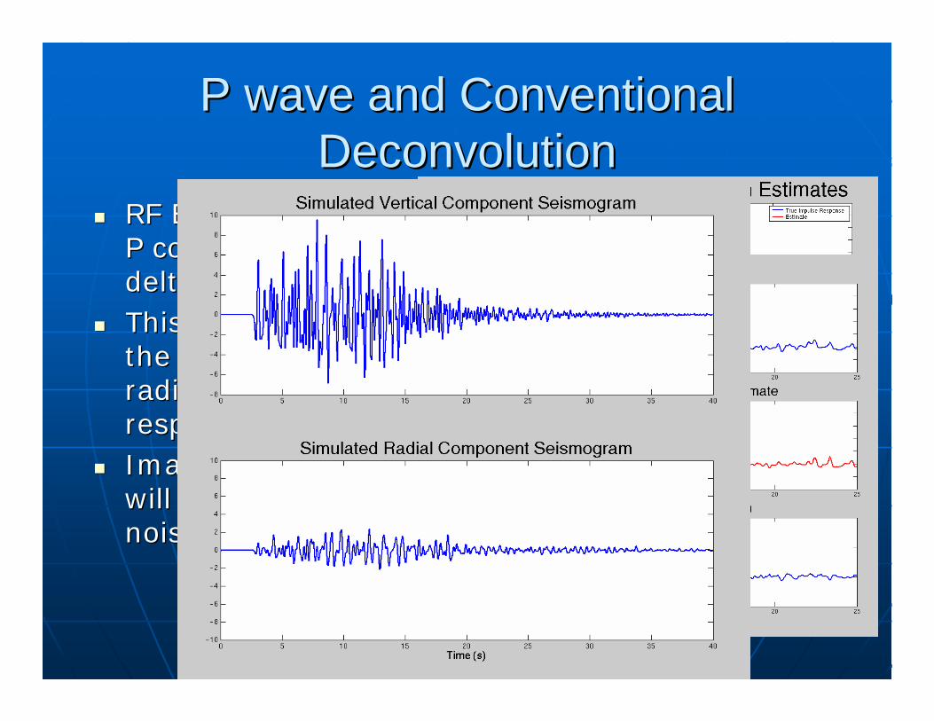
P wave and Conventional P wave and Conventional DeconvolutionDeconvolution
RF Estimates force RF Estimates force P component to P component to delta at zero lagdelta at zero lagThis example shows This example shows the RF is NOT the the RF is NOT the radial impulse radial impulse responseresponseImaging methods Imaging methods will treat residual as will treat residual as noisenoise
MultichannelMultichannel MethodsMethods
Why Why multichannelmultichannel??•• Emergence of broadband array data (e.g. IRIS Emergence of broadband array data (e.g. IRIS
PASSCAL) in the past 15 yearsPASSCAL) in the past 15 years•• Aim to exploit data redundancy Aim to exploit data redundancy •• Learn from experience of reflection seismologyLearn from experience of reflection seismology•• Some versions provide estimates of P impulse Some versions provide estimates of P impulse
responseresponse
Types:Types:•• Common receiver gathers Common receiver gathers •• Common event gathersCommon event gathers
Common receiver gather methodsCommon receiver gather methods
Most common approach: average Most common approach: average moveoutmoveout corrected RF estimates for corrected RF estimates for each stationeach stationSimultaneous timeSimultaneous time--domain domain deconvolutiondeconvolution ((GurrolaGurrola et al, 1995)et al, 1995)Wilson and Aster (2005) Wilson and Aster (2005) ff--kk filtering filtering (Subject of tutorial 2)(Subject of tutorial 2)
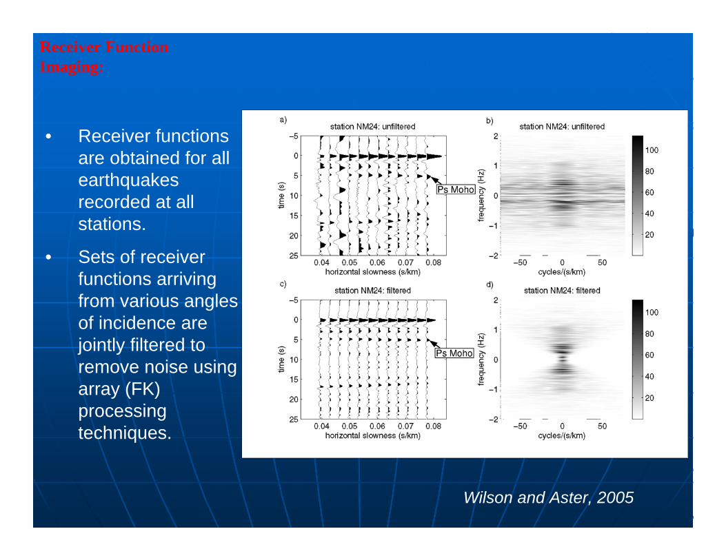
• Receiver functions are obtained for all earthquakes recorded at all stations.
• Sets of receiver functions arriving from various angles of incidence are jointly filtered to remove noise using array (FK) processing techniques.
Receiver Function Imaging:
Wilson and Aster, 2005
Common Event Gather MethodsCommon Event Gather Methods
Li and Li and NabalekNabalek (1999) method(1999) methodPrincipal component method Principal component method ((BostockBostock and and RondenayRondenay, 1999), 1999)PseudostationPseudostation stacking method (Neal stacking method (Neal and and PavlisPavlis, 1999,2000), 1999,2000)
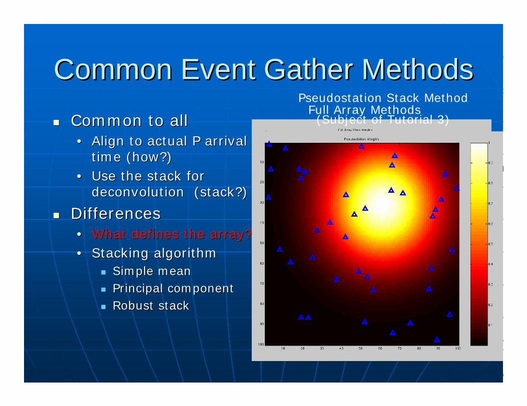
Common Event Gather MethodsCommon Event Gather MethodsCommon to allCommon to all•• Align to actual P arrival Align to actual P arrival
time (how?)time (how?)•• Use the stack for Use the stack for
deconvolutiondeconvolution (stack?)(stack?)
DifferencesDifferences•• What defines the array?What defines the array?•• Stacking algorithmStacking algorithm
Simple meanSimple meanPrincipal componentPrincipal componentRobust stack Robust stack
Full Array MethodsPseudostation Stack Method
(Subject of Tutorial 3)
Common Event Gather MethodsCommon Event Gather MethodsCommon to allCommon to all•• Align to actual P arrival Align to actual P arrival
timetime•• Use the stack for Use the stack for
deconvolutiondeconvolution
DifferencesDifferences•• What defines the array?What defines the array?•• Stacking algorithmStacking algorithm
Simple meanSimple meanPrincipal componentPrincipal componentRobust stackRobust stack
•• Nth rootNth root•• Coherence methodCoherence method
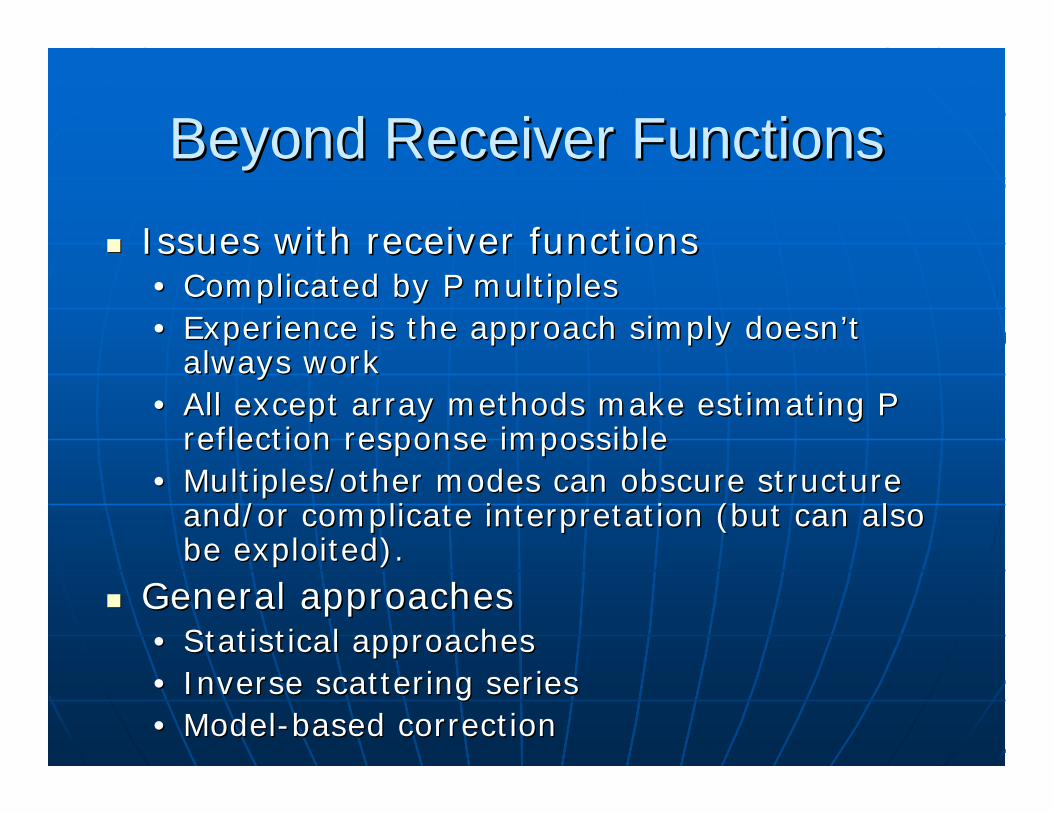
Beyond Receiver FunctionsBeyond Receiver FunctionsIssues with receiver functionsIssues with receiver functions•• Complicated by P multiplesComplicated by P multiples•• Experience is the approach simply doesn’t Experience is the approach simply doesn’t
always workalways work•• All except array methods make estimating P All except array methods make estimating P
reflection response impossiblereflection response impossible•• Multiples/other modes can obscure structure Multiples/other modes can obscure structure
and/or complicate interpretation (but can also and/or complicate interpretation (but can also be exploited).be exploited).
General approachesGeneral approaches•• Statistical approachesStatistical approaches•• Inverse scattering series Inverse scattering series •• ModelModel--based correctionbased correction
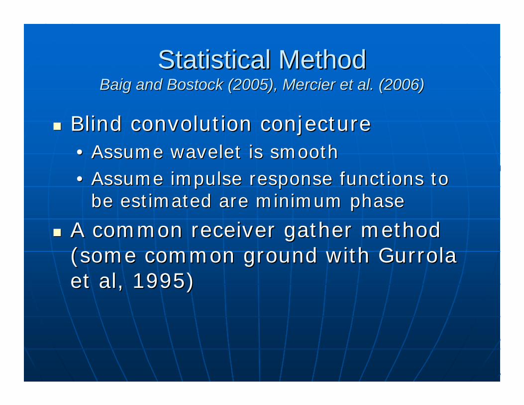
Statistical MethodStatistical MethodBaigBaig and and BostockBostock (2005), Mercier et al. (2006)(2005), Mercier et al. (2006)
Blind convolution conjectureBlind convolution conjecture•• Assume wavelet is smoothAssume wavelet is smooth•• Assume impulse response functions to Assume impulse response functions to
be estimated are minimum phasebe estimated are minimum phase
A common receiver gather method A common receiver gather method (some common ground with (some common ground with GurrolaGurrolaet al, 1995)et al, 1995)
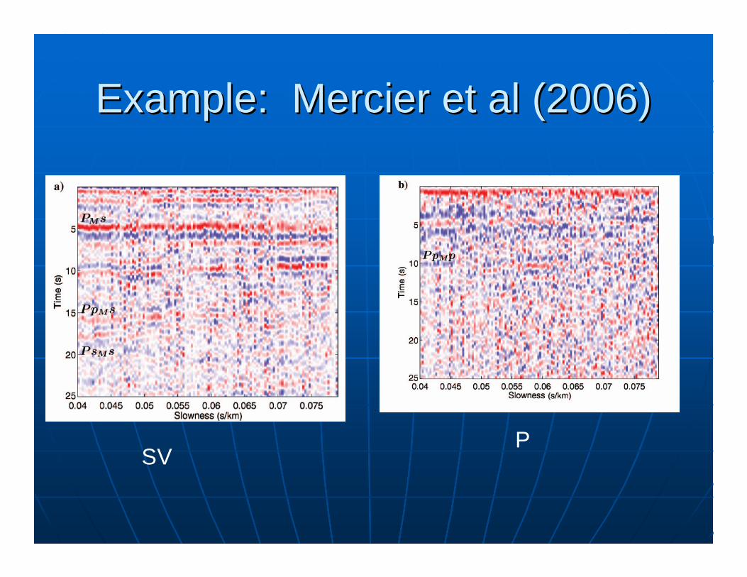
Example: Mercier et al (2006)Example: Mercier et al (2006)
SVP
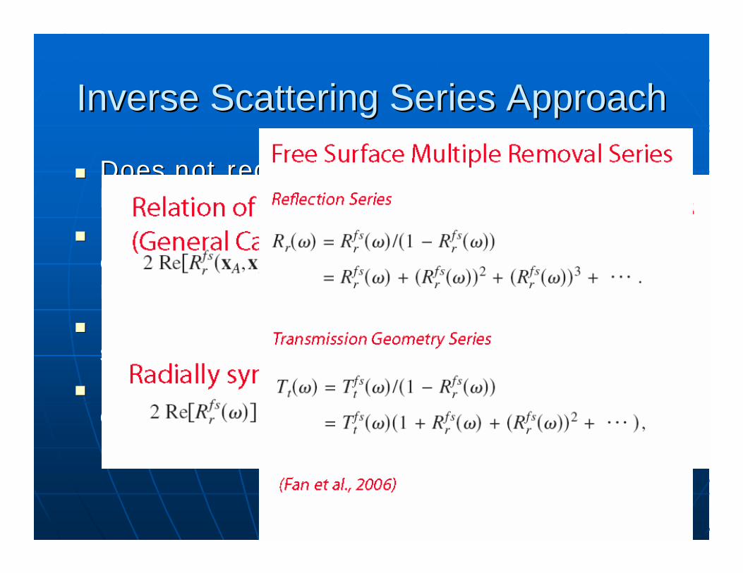
Inverse Scattering Series ApproachInverse Scattering Series Approach
Does not require earth model to Does not require earth model to be estimated at allbe estimated at allUses freeUses free--surface transformation surface transformation operator to get backscattered P operator to get backscattered P responseresponseRemove multiple with inverse Remove multiple with inverse scattering seriesscattering seriesRequires an accurate wavelet Requires an accurate wavelet estimateestimate
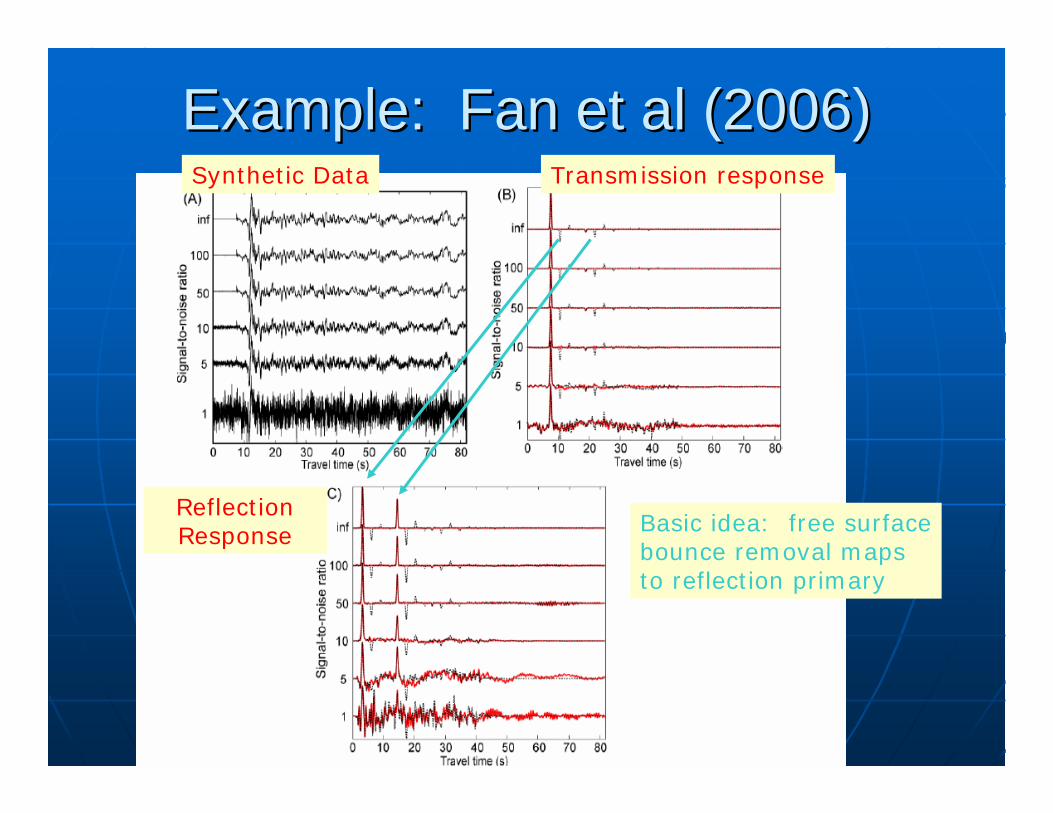
Example: Fan et al (2006)Example: Fan et al (2006)
Basic idea: free surface bounce removal maps to reflection primary
Synthetic Data Transmission response
Reflection Response
ModelModel--based Approach: based Approach: ConvolutionalConvolutional Model TheoryModel Theory
KEY CONCEPT: the source wavelet is KEY CONCEPT: the source wavelet is unknown AND a fundamental part of unknown AND a fundamental part of the problemthe problemdata = source * data = source * impulse_responseimpulse_responseThe source wavelet has a nonlinear The source wavelet has a nonlinear relationship to the real Earth’s relationship to the real Earth’s velocity and density structure velocity and density structure through the unknown impulse through the unknown impulse response functionresponse function
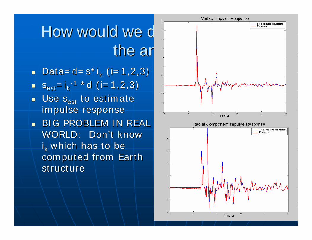
How would we do this if we knew How would we do this if we knew the answer?the answer?
Data=d=s*Data=d=s*iikk (i=1,2,3)(i=1,2,3)ssestest=i=ikk--11 *d (i=1,2,3)*d (i=1,2,3)Use Use ssestest to estimate to estimate impulse responseimpulse responseBIG PROBLEM IN REAL BIG PROBLEM IN REAL WORLD: Don’t know WORLD: Don’t know iikk which has to be which has to be computed from Earth computed from Earth structurestructure
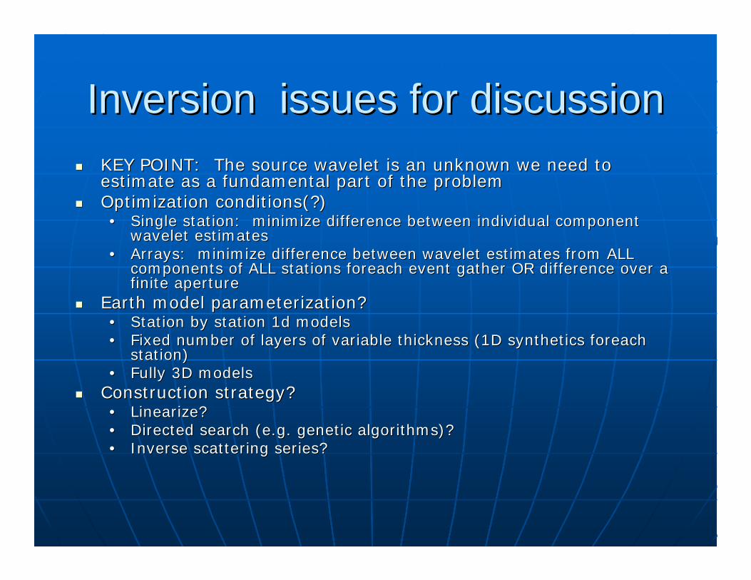
Inversion issues for discussionInversion issues for discussionKEY POINT: The source wavelet is an unknown we need to KEY POINT: The source wavelet is an unknown we need to estimate as a fundamental part of the problemestimate as a fundamental part of the problemOptimization conditions(?)Optimization conditions(?)•• Single station: minimize difference between individual componenSingle station: minimize difference between individual component t
wavelet estimateswavelet estimates•• Arrays: minimize difference between wavelet estimates from ALL Arrays: minimize difference between wavelet estimates from ALL
components of ALL stations components of ALL stations foreachforeach event gather OR difference over a event gather OR difference over a finite aperturefinite aperture
Earth model parameterization?Earth model parameterization?•• Station by station 1d modelsStation by station 1d models•• Fixed number of layers of variable thickness (1D synthetics Fixed number of layers of variable thickness (1D synthetics foreachforeach
station)station)•• Fully 3D models Fully 3D models
Construction strategy?Construction strategy?•• LinearizeLinearize??•• Directed search (e.g. genetic algorithms)?Directed search (e.g. genetic algorithms)?•• Inverse scattering series?Inverse scattering series?
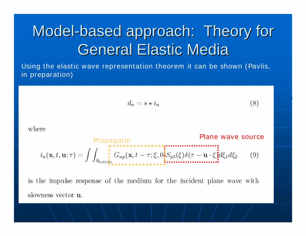
ModelModel--based approach: Theory for based approach: Theory for General Elastic MediaGeneral Elastic Media
Using the elastic wave representation theorem it can be shown (Pavlis, in preparation)
Plane wave sourcePropagator
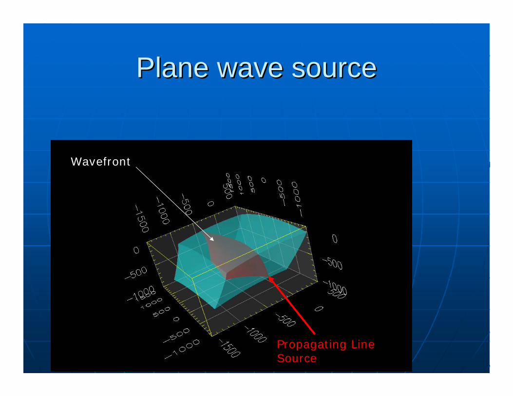
Plane wave source Plane wave source
Propagating Line Source
Wavefront
Forward Modeling and ImagingForward Modeling and Imaging
3D modeling problem requires plane 3D modeling problem requires plane wave syntheticswave syntheticsNeeded badly to explore limits of Needed badly to explore limits of current impulse generation current impulse generation capabilitiescapabilitiesNeeded badly to explore limits of Needed badly to explore limits of current imaging methodscurrent imaging methods
Summary of Key PointsSummary of Key PointsReceiver function estimation is a form of Receiver function estimation is a form of deconvolutiondeconvolutionReceiver functions are never the impulse response of the mediumReceiver functions are never the impulse response of the medium•• Not a problem for 1D model inversion because Not a problem for 1D model inversion because RFsRFs are data for are data for
inversioninversion•• Treating Treating RFsRFs as the impulse response will cause artifacts in all as the impulse response will cause artifacts in all
wavefield imaging AND limit resolutionwavefield imaging AND limit resolutionApproaches to do betterApproaches to do better•• MultichannelMultichannel methods methods
Common receiver methodsCommon receiver methodsCommon event methodsCommon event methodsStatistical methodsStatistical methods
•• Multiple removalMultiple removal•• Solving for the source wavelet as part of the problemSolving for the source wavelet as part of the problem•• Denser dataDenser data
Assertion: doing this right is one of the biggest barrier to Assertion: doing this right is one of the biggest barrier to progress with most dataprogress with most data
Discussion points on forward Discussion points on forward modeling:modeling:
What do we need to test imaging What do we need to test imaging algorithms?algorithms?What do we need to improve impulse What do we need to improve impulse response estimates? response estimates? Can global synthetics provide a workable Can global synthetics provide a workable source wavelet?source wavelet?Requires implementation of a planeRequires implementation of a plane--wave wave source conditionsource condition•• Feasible? Feasible? •• How should it be done (sum G sources or How should it be done (sum G sources or
produce family of plane waves?)produce family of plane waves?)Implementing a community model?Implementing a community model?
Other Discussion PointsOther Discussion Points
Questions for previous speakers?Questions for previous speakers?What are the key unsolved What are the key unsolved theoretical problems that limit what theoretical problems that limit what we can do in wavefield imaging?we can do in wavefield imaging?What are the main practical What are the main practical bottlenecks to progress for you?bottlenecks to progress for you?