Embed Size (px)
Citation preview

Estimation of Equivalent Thermal Conductivity for
Electrical Windings with High Conductor Fill
Factor
Sabrina Ayat
Electrical & Electronic Systems Group
Safran Tech
Châteaufort, France
Haipeng Liu
Electrical Energy Management Group
University of Bristol
Bristol, United Kingdom
Mehmet Kulan and Rafal Wrobel
Centre for Advanced Electrical Drives
Newcastle University
Newcastle upon Tyne, United Kingdom
Abstract— In order to improve accuracy and reduce model
setting up and solving time in the thermal analysis of electrical
machines, the multi-material winding region is frequently
homogenized. A typical electrical winding is an amalgam of the
conductor material, electrical insulation, impregnation and
imperfections like air cavities, which depend on the
impregnation material and technique, among other factors. This
makes the winding assembly one of the most challenging region
in thermal design of electrical machines. This paper presents an
analytical method for estimating the equivalent thermal
conductivity of impregnated windings formed with round
profile conductors. The existing analytical methods are limited
to windings with conductor fill factor up to 40%. However, the
ongoing development in fabricating windings enabled winding
arrangements with much higher conductor fill factors, up to
85%. Such high conductor fill is very desirable as it reduces the
winding DC power loss while improving the thermal path for
the generated heat. Thus, providing a reliable analytical
approach for the estimation of the equivalent thermal
conductivity, applicable across a wide range of conductor fill
factors, is very desirable. This paper presents a detailed
description of the proposed approach, supplemented with
measured data from tests on hardware winding material
samples (WSs). An illustration of a practical use of windings
with high conductor fill factors is also provided, highlighting the
benefits of such configuration.
Keywords—Winding region, homogenization, thermal
conductivity, electrical machine, hardware testing.
I. INTRODUCTION
The stator-winding assembly is usually attributed with the
dominant power loss component within the machine body
[1]-[5]. A well-informed design of the winding region is
therefore a pre-requisite of compact, high-power-density and
high-efficiency machine solutions, such as these adopted in
aerospace applications. Recent developments in the field of
electrical machine design focus on solutions with improved
thermal performance and reduced-loss generation, such as
high conductor fill factor compressed coils [6]-[11].
The existing methods for estimating of the winding’s
thermal parameters must be adapted to the ongoing evolution
and improvement in fabricating of the electrical windings [1]-
[4]. The existing analytical methods for deriving of the
equivalent thermal conductivity for windings formed with
round profile conductors are limited to conductor fill factor
(FF) up to 40% [2]. Alternative techniques of deriving the
winding equivalent thermal conductivity employ
experimental or numerical methods. The analytical methods
developed for the rectangular and Litz wire based winding
topologies make use of lumped-parameter thermal equivalent
circuit (TEC) approach to estimate the winding equivalent
thermal conductivity [3], [4]. These methods account for
thermal path of the heat flux across the impregnated
conductors. Such approach ensures improved accuracy as
compared with the existing analytical approaches, which are
predominantly based on volumetric contribution of the
constituent materials within the winding amalgam [2].
Fig. 1 Impregnated winding samples, a) Close-up view on a conventional
winding (FF=55%) [2], b) Close-up view on a compressed winding (FF=80%) [7], c) A pre-compressed coil exemplar [7]
This work is focused on developing an analytical approach
for the estimation of the equivalent thermal conductivity of
impregnated electrical windings formed with round
conductors. One of the key challenges associated with the
development of a method for estimating the equivalent
thermal conductivity for windings with high conductor fill
factor using TEC, is to understand how the individual
conductors deform when compressed in a coil forming fixture
[6]-[11]. The high conductor fill factor leads to plastic
deformation of the conductors’ profile from round to
polygonal as shown in Figs. 1a) and 1b). Also, Fig. 1c) shows
an example of a complete preformed coil with a high
conductor fill factor (80%) for a high specific output machine
design [7]. The winding technique employed here enables
geometrically accurate coil fabrication. It is expected that the
manner, in which the individual conductors deform depends
on the overall coil geometry and the winding compression
technique.
In this investigation, a simplified mechanical analysis has
been carried out to gain an insight into the mechanical aspects
of the winding construction with high conductor fill factor.
The approach used here employs a two-dimensional (2D)
mechanical finite element (FE) analysis similar to that
presented in [3], [4]. The theoretical findings from the FE
analysis have been used to inform the proposed technique for
estimating the equivalent thermal conductivity using the TEC
approach. The method relies on an averaged conductor
profile. The theoretical predictions from the new method
have been compared with data from the existing numerical

technique showing good correlation. Also, the theoretical
body of work has been supplemented with experimentally
derived results from tests on several winding samples.
Finally, a case study thermal analysis of a machine for
aerospace application is presented, highlighting the
importance of reliable thermal data for the analysis of high
specific output electrical machines. The benefits of using
winding formed with compressed conductors are also
emphasized.
II. WINDING MATERIAL SAMPLES
Several winding samples (WSs) have been manufactured
for the purpose of this research. Figs. 1 and 2 present the
selected winding samples together with relationship between
them. The winding samples were carefully chosen to differ in
terms of conductor fill factor and impregnation material. The
variety of the analyzed samples enables here a more generic
insight into the composite winding thermal properties and
their dependence on the geometrical, material and
manufacturing factors. Table I presents basic data for the
analyzed winding samples.
A heat flux meter approach has been employed in this
investigation to measure the thermal conductivity of the WSs
[1]-[5]. During the test, a known heat transfer rate is applied
by dissipating a pre-set power in a power resistor. The tested
winding sample is placed on a temperature-controlled cold
plate inside a thermally insulated chamber to ensure a
unidirectional heat transfer. Fig. 3 presents a photograph of
the experimental set-up, before surrounding the winding
sample with thermal insulating material.
TABLE I. BASIC DATA FOR THE ANALYZED IMPREGNATED WINDING
SAMPLES
Winding sample (WS) I II III IV V VI
Fill factor FF [%] 55 60 66 60 55 80
Conductor radius [mm] 0.8 0.35 0.8 0.8 0.8 0.75 Conductor material Cu Cu Al Cu Al Al
Electrical insulation
material
1 1 1 1 2 1
Impregnation material 3 4 4 4 4 -
Electrical insulation
thickness [µm]
35 35 35 35 3.5 42
1Polyamide-imide enamel, 2Aluminium oxide, 3Varnish (Ultimeg 2000/380), 4Epoxy resin (Epoxylite EIP 4260).
Fig. 2 Relationship between the analyzed impregnated WSs
Fig. 3 Experimental set-up before surrounding the winding sample with
thermal insulating material
A set of thermocouples are embedded in the sample on each
face to allow the average temperature measurements to be
taken. A thermally-conductive paste is applied to both
interfaces to improve the contact heat transfer. A detailed
description of the experimental set-up together with the
testing procedure, is provided in the authors’ previous work
[1]-[4]. The thermal conductivity is derived from,
𝑘 =(𝑅Ω𝐼2)𝑙
(𝑇1−𝑇2)𝐴=
𝑃Ω.𝑙
(𝑇1−𝑇2)𝐴 (1)
where I represents the DC current excitation applied to the
resistor 𝑅Ω , l the distance between measuring points for
temperature 𝑇1 and 𝑇2 , and A the cross-section area of the
sample through which the heat is transferred. The applied
current and voltage are both measured when the steady-state
is reached in order to account for the effect of temperature on
the ohmic resistance value. Table II includes a set of
measured thermal conductivities for each of the selected
winding samples, with measurement uncertainty estimated
using the propagation of error formula [16].
TABLE II. MEASURED SET OF THERMAL CONDUCTIVITIES FROM TESTS ON
WINDING SAMPLES
Winding sample 𝑘𝑥
[W/(m∙K)]
𝑘𝑦
[W/(m∙K)]
𝑘𝑧
[W/(m∙K)]
I 2.1±0.1 2.1±0.1 - II 2.0±0.1 2.5±0.1 166±6
III 2.4±0.1 2.3±0.1 151±5
IV 2.5±0.1 2.7±0.1 215±8 V 6.5±0.2 6.3±0.2 167±6
VI 2.0±0.1 2.0±0.1 -
As expected, the thermal conductivity in x-axis is similar to
the one in y-axis for round conductors. The use of aluminum
conductor instead of copper has limited impact on the
equivalent winding thermal conductivity, WSs II and III. The
use of epoxy resin impregnation has shown improved overall
thermal properties of the impregnated winding samples, e.g.
WSs I and IV. This results from better material thermal
properties and improved encapsulating properties for the
epoxy impregnation as compared with the varnish
impregnation. The limiting factors are the impregnation and
electrical insulation materials. This is confirmed by the
difference between WSs III and V. These two samples use
identical conductors with different type of electrical
insulation material (conductor coating). Here, the use of
aluminum oxide instead of enamel results in a 170 % increase
in the winding thermal conductivity. The compressed
winding sample, WS VI, offers an equivalent thermal
conductivity comparable to WSs I, II, III and IV without any
form of impregnation. This is of interest when optimizing the
machine manufacturing process. Indeed, replacing the
winding impregnation by the winding compression could
decrease the machine construction time and resources, i.e.
time and equipment required to cure the impregnation, and
cost, i.e. material and processing cost.
III. CONVENTIONAL WINDINGS FORMED WITH
ROUND-PROFILE CONDUCTORS
The numerical and analytical methods have been
commonly used to derive the equivalent winding thermal
conductivity of impregnated winding formed with round-
profile conductors. The numerical method makes use of FE
analyses, while the proposed method makes use of the TEC
approach.
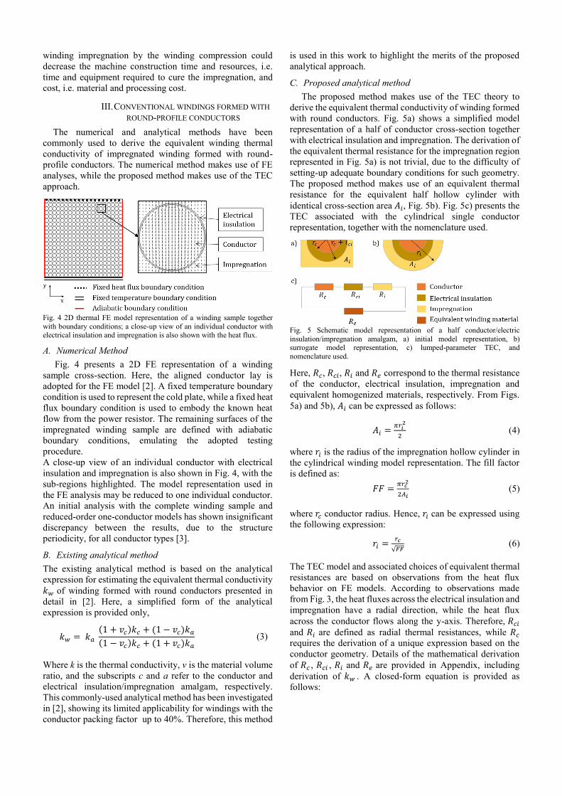
Fig. 4 2D thermal FE model representation of a winding sample together
with boundary conditions; a close-up view of an individual conductor with electrical insulation and impregnation is also shown with the heat flux.
A. Numerical Method
Fig. 4 presents a 2D FE representation of a winding
sample cross-section. Here, the aligned conductor lay is
adopted for the FE model [2]. A fixed temperature boundary
condition is used to represent the cold plate, while a fixed heat
flux boundary condition is used to embody the known heat
flow from the power resistor. The remaining surfaces of the
impregnated winding sample are defined with adiabatic
boundary conditions, emulating the adopted testing
procedure.
A close-up view of an individual conductor with electrical
insulation and impregnation is also shown in Fig. 4, with the
sub-regions highlighted. The model representation used in
the FE analysis may be reduced to one individual conductor.
An initial analysis with the complete winding sample and
reduced-order one-conductor models has shown insignificant
discrepancy between the results, due to the structure
periodicity, for all conductor types [3].
B. Existing analytical method
The existing analytical method is based on the analytical
expression for estimating the equivalent thermal conductivity
𝑘𝑤 of winding formed with round conductors presented in
detail in [2]. Here, a simplified form of the analytical
expression is provided only,
𝑘𝑤 = 𝑘𝑎
(1 + 𝑣𝑐)𝑘𝑐 + (1 − 𝑣𝑐)𝑘𝑎
(1 − 𝑣𝑐)𝑘𝑐 + (1 + 𝑣𝑐)𝑘𝑎
(3)
Where k is the thermal conductivity, v is the material volume
ratio, and the subscripts c and a refer to the conductor and
electrical insulation/impregnation amalgam, respectively.
This commonly-used analytical method has been investigated
in [2], showing its limited applicability for windings with the
conductor packing factor up to 40%. Therefore, this method
is used in this work to highlight the merits of the proposed
analytical approach.
C. Proposed analytical method
The proposed method makes use of the TEC theory to
derive the equivalent thermal conductivity of winding formed
with round conductors. Fig. 5a) shows a simplified model
representation of a half of conductor cross-section together
with electrical insulation and impregnation. The derivation of
the equivalent thermal resistance for the impregnation region
represented in Fig. 5a) is not trivial, due to the difficulty of
setting-up adequate boundary conditions for such geometry.
The proposed method makes use of an equivalent thermal
resistance for the equivalent half hollow cylinder with
identical cross-section area 𝐴𝑖, Fig. 5b). Fig. 5c) presents the
TEC associated with the cylindrical single conductor
representation, together with the nomenclature used.
Fig. 5 Schematic model representation of a half conductor/electric
insulation/impregnation amalgam, a) initial model representation, b) surrogate model representation, c) lumped-parameter TEC, and
nomenclature used.
Here, 𝑅𝑐, 𝑅𝑐𝑖, 𝑅𝑖 and 𝑅𝑒 correspond to the thermal resistance
of the conductor, electrical insulation, impregnation and
equivalent homogenized materials, respectively. From Figs.
5a) and 5b), 𝐴𝑖 can be expressed as follows:
𝐴𝑖 =𝜋𝑟𝑖
2
2 (4)
where 𝑟𝑖 is the radius of the impregnation hollow cylinder in
the cylindrical winding model representation. The fill factor
is defined as:
𝐹𝐹 =𝜋𝑟𝑐
2
2𝐴𝑖 (5)
where 𝑟𝑐 conductor radius. Hence, 𝑟𝑖 can be expressed using
the following expression:
𝑟𝑖 =𝑟𝑐
√𝐹𝐹 (6)
The TEC model and associated choices of equivalent thermal
resistances are based on observations from the heat flux
behavior on FE models. According to observations made
from Fig. 3, the heat fluxes across the electrical insulation and
impregnation have a radial direction, while the heat flux
across the conductor flows along the y-axis. Therefore, 𝑅𝑐𝑖
and 𝑅𝑖 are defined as radial thermal resistances, while 𝑅𝑐
requires the derivation of a unique expression based on the
conductor geometry. Details of the mathematical derivation
of 𝑅𝑐 , 𝑅𝑐𝑖 , 𝑅𝑖 and 𝑅𝑒 are provided in Appendix, including
derivation of 𝑘𝑤 . A closed-form equation is provided as
follows:

𝑘𝑤 =1
ln𝑟𝑐
(𝑟𝑐+𝑡𝑐𝑖)√𝐹𝐹
𝑘𝑖+
ln𝑟𝑐+𝑡𝑐𝑖
𝑟𝑐𝑘𝑐𝑖
+1
𝑘𝑐
(7)
The assumptions made in the derivation of 𝑘𝑤, such as the
radial heat transfer across the electrical insulation material, is
only valid for 𝑘𝑐 >>𝑘𝑐𝑖 . This is generally the case for the
winding amalgams. However, if uncommon materials were
to be used, the formula might require a revision.
D. Initial Comparison
In order to demonstrate applicability and limitations of
proposed method, 𝑘𝑤 has been estimated for WS-I’s
configuration. Fig. 6 presents variation of the equivalent
thermal conductivity versus conductor fill factor assuming
fixed cross-section of an individual conductor. Each plot
corresponds to a specific value of 𝑘𝑖 from 0.5 W/(m.°C) to
1.1 W/(m.°C). The thermal conductivity values of conductor
material and electrical insulation are kept constant, 𝑘𝑐 = 380
W/(m.°C) (Cu conductors) or 𝑘𝑐 = 215 W/(m.°C) (Al
conductors), and 𝑘𝑐𝑖 = 0.27W/(m.°C) (Polyamide-imide
enamel) or 𝑘𝑐𝑖 = 2.0 W/(m.°C) (Aluminum oxide),
respectively.
The proposed analytical method shows very good
correlation with the numerical method, while the limited
applicability of the existing analytical method at high
conductor fill factor is confirmed, in particular for conductor
fill factors superior to 55%. The existing analytical method
has been originally developed for two-material composites in
[15], and has been adapted in [2] to three-material amalgams.
Therefore if 𝑘𝑖 is dissimilar to 𝑘𝑐𝑖 , the initial assumptions
made in [15] considering a two-material composite may no
longer be valid.
Fig. 6 Predicted thermal conductivity vs. conductor fill factor for different
impregnation ‘goodness’
Fig. 7 Thermal conductivity vs. conductor radius
Fig. 7 presents the variations of the equivalent thermal
conductivity versus conductor radius assuming a fixed fill
factor of the winding assembly, FF=55%. On the one hand,
the proposed analytical method shows again very good
correlation with the results from the existing analytical
method. On the other hand, the applicability of the existing
analytical method appears limited when the electrical
insulation thickness 𝑡𝑐𝑖 is not negligible compared to the
conductor radius 𝑟𝑐 . In this case, the winding assembly cannot
be considered a two-material composite, and the initial
assumptions made in [15] may again no longer be valid.
Table III presents the measured and calculated thermal
conductivity values from WSs II to V. The measured thermal
conductivity values in the x- and y- axes have been averaged
to obtain a single value for the comparison. The impregnation
thermal conductivity values 𝑘𝑖 used in the FE model have
been tuned to match the measured results. Then, these
calibrated 𝑘𝑖 have been used to calculate the winding
equivalent thermal conductivity 𝑘𝑤 using the proposed
analytical method. The results correlate well, with a
maximum deviation of 10% observed between WS II’s
calculated data.
TABLE III. AVERAGE MEASURED AND CALCULATED SETS OF THERMAL
CONDUCTIVITIES OF WINDING SAMPLES
Winding sample II III IV V
𝑘𝑤,𝑚𝑒𝑎𝑠𝑢𝑟𝑒𝑑 (𝑎𝑣𝑒𝑟𝑎𝑔𝑒) [W/(m.°C)] 2.25 2.35 2.6 6.4
𝑘𝑤,𝑐𝑎𝑙𝑐𝑢𝑙𝑎𝑡𝑒𝑑−𝐹𝐸 𝑚𝑒𝑡ℎ𝑜𝑑 [W/(m.°C)] 2.2 2.35 2.6 6.4 𝑘𝑤,𝑐𝑎𝑙𝑐𝑢𝑙𝑎𝑡𝑒𝑑−𝑝𝑟𝑜𝑝𝑜𝑠𝑒𝑑 𝑚𝑒𝑡ℎ𝑜𝑑
1 [W/(m.°C)] 2.0 2.35 2.55 6.3 1 Calculated using the impregnation thermal conductivity derived from FE calibration
IV. WINDINGS FORMED WITH ROUND-PROFILE COMPRESSED
CONDUCTORS
A. Mechanical Analysis
A structural FE approach has been used here to derive
deformed winding samples for different conductor fill
factors. A plastic deformation of compressed windings can be
modelled using an appropriate FE solver, e.g. a quasi-static
explicit dynamic. Such analysis is effectively based on a
dynamic phenomenon as is in the physical structure. The
compression of a coils/winding sample is highly non-linear
computational problem due to the geometrical, material
stress-strain relationship and frictional body interactions
between the individual conductors. The quasi-static explicit
dynamic analysis is preferred here in contrast to a more
conventional static structural FE approach.
A FE model of a 15-turn coil with aluminium conductors
has been solved to mimic the winding sample compression,
Fig. 8. A velocity boundary conditions have been applied on
the steel punches positioned on the sides of the winding
segment to compress the conductors. The approach employed
here is similar to that presented in [10], used to derive
deformed conductor geometry for different slot fill factors.
Since FE boundary conditions and solver settings are of
significant importance for the accuracy of the simulations,
conservation of energy in the overall system needs to be
monitored to ensure that the mesh deformation is realistic
[10].

Fig.8 Quasi-static FE stress analysis of a compressed coil
This has been achieved in Fig. 8 with a maximum fill factor
of 80%. Theoretical predictions suggest that further
compression of the geometry would result in the insulation
failure assuming a polymer-based wire insulation’s stress-
strain curve. The realistic compressed winding geometries
obtained from the mechanical analysis have been used for the
estimation of the equivalent thermal conductivity of the
compressed windings at various fill factors.
B. Thermal analysis
Four initial examples of compacted windings with different
conductor fill factors have been selected from the mechanical
FE analysis to investigate their equivalent thermal properties,
Fig. 9. The FE thermal model definition employed here is
similar to that discussed earlier in Section III. However, for
the compressed windings, the conductor fill factor is too high
to reduce the FE thermal model to just one conductor, Fig. 4.
Consequently, a model definition encompassing two-
conductors has been used as shown in Fig. 9. Here, the first,
complete conductor is placed in the center while four quarters
of the second conductor are located in each corner of the FE
model. It has been assumed in the FEAs that thermal
conductivity of air is equal to 𝑘𝑎𝑖𝑟 =0.036 W/(m.°C). As
previously mentioned, the conductors may deform in an
irregular manner, depending on the adopted compression
approach. As a consequence, the equivalent winding thermal
conductivity may become anisotropic. Fig. 10 presents the 2D
FE representation of the compressed winding cross-section,
highlighting the temperature distribution within the
conductors.
Fig. 11 presents the calculated thermal conductivity, for both
x- and y-axes. The measured data point from tests on the
compressed winding sample is also shown. The results
confirm the expected thermal anisotropy, which depends on
the way the conductors deform.
Fig.9 Compressed winding geometries selected for the thermal analysis
Fig.10 2D thermal FEA model representation of a winding sample together
with boundary conditions, a) x-axis, b) y-axis.
Fig.11 Thermal conductivity vs. conductor fill factor for the analyzed
winding examples
The averaged winding thermal conductivity increases with
the winding fill factor. The measured value appears lower
than the theoretical estimates. This is due to the perfect
contact between the electrical insulation conductors assumed
in the FE model. Indeed, after the mechanical analysis, the
electrical insulation regions that are in contact merge together
forming a ‘merged electrical insulation region’. In practice,
the interface between the regions is imperfect and impacts the
winding thermal behavior.
An equivalent thermal conductivity could be defined for
the ‘merged electrical insulation region’, accounting for the
thermal contact resistance. In the analyzed case, the
equivalent thermal conductivity is equal to 𝑘𝑒= 0.2 W/(m.°C)
This is to calibrate the FE model with the measured data. Due
to the change in conductor shape during compression, and the
direct contact between conductors, the formula developed for
conventional windings formed with round conductors cannot
be directly applied to compressed windings. An analysis
based on the observation of the heat flux within the winding,
as presented in Section III, could be employed in developing
of the analytical method for the compressed windings. In
particular, the air gaps between conductors observed on Fig.
8 tends to have triangular shapes, and could therefore be
easily represented via a TEC approach. More work is
nonetheless required to account for the conductor
deformation.

V. ILLUSTRATION
A radial-flux interior permanent magnet (IPM) machine
designed for a steering application has been investigated to
illustrate the effect of using compressed winding on the
machine power output capability. Fig. 12 presents the
machine structure with all the active regions indicated. The
machine’s stator has an open-slot topology, which permits the
insertion of the compressed windings. To improve the heat
extraction from the winding body to the machine’s periphery,
ensure an adequate electrical insulation and a good
mechanical rigidity, the complete stator-winding assembly is
impregnated with varnish and housed in a standard flange
mounted aluminum frame. Basic machine data is listed in
Table IV.
TABLE IV. BASIC MACHINE DATA
Outer Diameter/ Active Length 180 mm/ 160 mm
Number of poles/slots 10/12
Base rotational speed 4600 rpm
Rated torque 62 N∙m
DC link voltage 340 V
Cooling type Water jacket Cooling temperature 70 °C
Electrical insulation class H (180 °C)
A three-dimensional (3D) TEC has been built to predict the
machine steady state and transient torque output capability,
using cuboidal and arc-segment elements [1], [17]. The active
and end winding assemblies are modelled based on the
homogenized winding thermal properties, predicted using
(8). The thermal properties of other materials, including
laminated stator and rotor core packs (M270-35A), PM array
(SmCo), shaft (Stainless Steel), end-cap and housing frame
(Aluminium) are obtained from the available literature [18],
[19]. More details about the thermal network are available in
the author’s previous work [6], [8].
Fig. 12 A schematic drawing of the investigated PM machine assembly
with active regions indicated.
TABLE V. CALCULATED DATA FOR THE SELECTED EXAMPLES
FF [%] 𝑟𝑐 [mm] 𝑘𝑤[W/(m.°C)] 𝑐𝑠,𝑤 [J/°C]
65 0.74 2.5 483 75 0.79 3.3 442
85 0.85 4.6 408
The impact of three different conductor fill factors (65%,
75% and 85%) on the machine continuous and transient
thermal envelopes has been investigated. Only the
conductors’ radius 𝑟𝑐 is varied, i.e. the number of turns and
winding connections are kept unchanged. The equivalent
winding thermal conductivity values have been calculated for
the three examples, and are listed in Table V. The winding
specific heat capacity 𝑐𝑠,𝑤 has been calculated using (8), [2],
𝑐𝑠,𝑤 =𝑃𝐹(𝜌𝑐𝑐𝑠,𝑐−𝜌𝑖𝑐𝑠,𝑖)+𝜌𝑖𝑐𝑠,𝑖
𝑃𝐹(𝜌𝑐−𝜌𝑖)+𝜌𝑖 (8)
where PF is the packing factor, i.e. the ratio of wire to
complete winding, ρ and 𝑐𝑠 are the density and the specific
heat capacity, respectively. According to [2], the electrical
insulation can be neglected when calculating the winding
equivalent specific heat capacity.
The ratio of equivalent AC and DC winding resistances,
(𝑅𝑎𝑐/𝑅𝑑𝑐) is expressed as follows:
(𝑅𝑎𝑐
𝑅𝑑𝑐)
𝑇0
(𝑓) = ((𝑅𝑎𝑐
𝑅𝑑𝑐)
𝑇0,𝑓𝑚𝑎𝑥
− 1) (𝑓
𝑓max)
2
+ 1 (9)
where (𝑅𝑎𝑐
𝑅𝑑𝑐)
𝑇0,𝑓𝑚𝑎𝑥
is the ratio of equivalent AC to DC
resistances at a reference temperature 𝑇0 and at a maximum
excitation frequency 𝑓𝑚𝑎𝑥 . The open-slot topology, required
for the compressed winding assembly, is expected to results
in elevated AC effects due to the rotor rotation for the
conductors at the top of the slot. However, aluminum
conductors are used in this machine. The high resistivity of
aluminum will result in different AC and DC winding loss
distributions than when copper conductors are used, with
lower AC and higher DC winding loss components. The ratio
has been kept constant for the selected examples, here,
(𝑅𝑎𝑐
𝑅𝑑𝑐)
𝑇0,𝑓𝑚𝑎𝑥
=3. The winding AC power loss are still likely to
be higher for windings with high fill factor if no particular
measures are taken to reduce them. Future work will include
analysis of the impact of the conductor radius on the AC
winding power loss. The functional representation of the AC
winding power loss temperature dependence, proposed in
[20], has been used when updating the losses with
temperature:
𝑃𝑎𝑐|𝑇0= 𝑃𝑑𝑐|𝑇0
(1 + 𝛼(𝑇 − 𝑇0)) +𝑃𝑑𝑐|𝑇0
(𝑅𝑎𝑐𝑅𝑑𝑐
)|𝑇0
−1
(1+𝛼(𝑇−𝑇0))𝛽 (10)
where β is the temperature coefficient for the ac loss
component and 𝑇0 is the temperature at which the DC power
loss 𝑃𝑑𝑐 has been calculated. The parameter β has been
derived from a curve fit of (10) to the winding AC power loss
data derived from FEAs at two reference temperatures. The
average winding temperature has been limited to 165 °C in
the continuous and transient thermal envelopes calculations.
Fig. 13 presents the calculated continuous and transient
thermal envelopes for the machines with alternative
conductor fill factors. The change in conductor fill factor has
more impact on the machine transient torque capability than
on the machine continuous torque capability, with an increase
of approximately 15% observed on the complete machine
torque/speed envelope when replacing a 65% fill factor with
an 85%, compared to an increase of approximately 21% at
machine rotation speed inferior to 5000 rpm. At high
rotational speed, the transient torque is constrained by the
maximum DC link voltage, and not by the winding maximum
temperature. Therefore, there are no difference in the
transient torques for the investigated examples in this context.

Fig. 13 Continuous and transient torque for machine alternatives with
different conductor fill factors.
The torque speed envelope with winding thermal limit is
influenced by the winding equivalent thermal conductivity,
winding equivalent heat capacity and winding electrical
resistance, all of which are simultaneously influenced by the
conductor fill factor. To illustrate the influence of conductor
fill factor on the winding thermal conductivity, and provide
more details on the winding temperature distribution, steady-
state FE thermal analyses have been completed on a single
stator segment, Fig. 14. The winding-to-stator contact
thermal contact resistance and the core thermal conductivity
are kept unchanged for the three investigated examples. An
equivalent convection boundary condition of 70 and 1000
W/(m².K) is applied to the stator outer boundary to account
for the stator-to-water jacket thermal contact resistance and
the water jacket cooling. A DC winding power loss of 70 W
is input to the winding region for the three examples. The
change in conductor fill factor has limited influence on the
winding average temperature. However, there is a clear
difference in the temperature gradient for windings with
different conductor fill factors, Fig. 14. There is 11%
reduction in hot spot temperature rise for winding with 85%
conductor fill factor compared with that with 65% conductor
fill factor. In practice, the winding loss will not be
homogeneously distributed within the winding assembly, and
therefore the difference in hot spot temperature is expected to
be more important. The inhomogeneous winding loss
distribution can be accounted for in a simple manner by
subdividing the winding area into smaller sub-regions, with
appropriate winding loss share [20].
Fig. 13 Winding temperature distribution for stator segment with different
conductor fill factors when same winding power loss are assumed. a)
FF=65%. b) FF=75%. c) FF=85%
VI. CONCLUSIONS
This paper presents an analytical approach for the
estimation of the equivalent thermal conductivity of
impregnated electrical windings formed with round
conductors. The formula has shown improved accuracy
compared to the existing analytical techniques for conductor
fill factors up to 75%. The theoretical analysis has been
supplemented with measured data from tests on hardware
winding material samples. In this context, the validity of the
calibrated thermal conductivity of impregnation for
alternative winding configurations has been confirmed.
An insight into the mechanical and thermal aspects of
winding constructions with high conductor fill factor has
been gained. The use of a higher conductor fill factor results
in a notable increased winding equivalent thermal
conductivity and reduced winding DC power losses. The
thermal conductivity value highly depends on the way the
conductors deform during compression, and may be
anisotropic depending on the adopted compression approach.
First observations on the derived numerical data constitutes a
first step into the development of a more generic analytical
formula for compressed windings. In particular, the triangular
shapes of the air gap between conductors after winding
compression seem well-suited for a lumped-parameter TEC
representation.
The use of the compressed conductor has been illustrated
on a PM machine designed for a steering application. A
notable increase in the machine continuous and transient
torque output capability has been observed. This work used
the improved conductor fill factor permitted by the
compression to increase the conductor radius. Different
winding modifications could also be considered, such as a
change in number of turns. The investigated machine’s duty
cycle is a combination of continuous and transient operation.
The analysis of the machine performance for a representative
operating cycle would offer complete information concerning
the total gain offered by compressed coil. For machines with
short transient application, such as the auxiliary motors used
to quickly restart the engine in Safran “more electric” twin-
engine helicopters [21], compressed windings can be
considered as a promising arrangement.
VII. APPENDIX
According to observations made from Fig. 4, the heat
fluxes across the electrical insulation and impregnation have
a radial direction, while the heat flux across the conductor
flows along y-axis. The radial thermal resistance in a hollow
cylinder, 𝑅𝑟,ℎ𝑜𝑙𝑙𝑜𝑤 , and half hollow cylinder, 𝑅𝑟,ℎ𝑜𝑙𝑙𝑜𝑤,ℎ𝑎𝑙𝑓
are obtained from the well-known solution of the heat
conduction equation with zero heat generation and expressed
as follows, respectively [14]:
𝑅𝑟,ℎ𝑜𝑙𝑙𝑜𝑤 =ln
𝑟2𝑟1
2𝜋𝑘𝐿 (11)
𝑅𝑟,ℎ𝑜𝑙𝑙𝑜𝑤,ℎ𝑎𝑙𝑓 =ln
𝑟2𝑟1
𝜋𝑘𝐿 (12)
where L, 𝑟1 and 𝑟2 are the hollow cylinder height, inner and
outer radius. The thermal resistances 𝑅𝑐𝑖 and 𝑅𝑖, are derived
from (13) and (14),
𝑅𝑖 =ln
𝑟𝑖𝑟𝑐𝑖
𝜋𝑘𝑖𝐿 (13)
𝑅𝑐𝑖 =ln
𝑟𝑐𝑖𝑟𝑐
𝜋𝑘𝑐𝑖𝐿 (14)
The thermal resistance across a half cylinder is derived in this
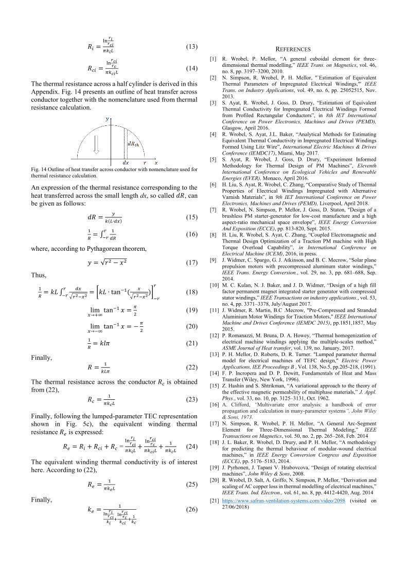
Appendix. Fig. 14 presents an outline of heat transfer across
conductor together with the nomenclature used from thermal
resistance calculation.
Fig. 14 Outline of heat transfer across conductor with nomenclature used for
thermal resistance calculation.
An expression of the thermal resistance corresponding to the
heat transferred across the small length dx, so called 𝑑𝑅, can
be given as follows:
𝑑𝑅 =𝑦
𝑘(𝐿∙𝑑𝑥) (15)
1
𝑅= ∫
1
𝑑𝑅
𝑟
−𝑟 (16)
where, according to Pythagorean theorem,
𝑦 = √𝑟2 − 𝑥2 (17)
Thus,
1
𝑅= 𝑘𝐿 ∫
𝑑𝑥
√𝑟2−𝑥2
𝑟
−𝑟= [𝑘𝐿 ∙ tan−1(
𝑥
√𝑟2−𝑥2)]
−𝑟
𝑟
(18)
lim𝑥→+∞
tan−1 𝑥 =𝜋
2 (19)
lim𝑥→−∞
tan−1 𝑥 = −𝜋
2 (20)
1
𝑅= 𝑘𝑙𝜋 (21)
Finally,
𝑅 =1
𝑘𝐿𝜋 (22)
The thermal resistance across the conductor 𝑅𝑐 is obtained
from (22),
𝑅𝑐 =1
𝜋𝑘𝑐𝐿 (23)
Finally, following the lumped-parameter TEC representation
shown in Fig. 5c), the equivalent winding thermal
resistance 𝑅𝑒 is expressed:
𝑅𝑒 = 𝑅𝑖 + 𝑅𝑐𝑖 + 𝑅𝑐 = ln
𝑟𝑖𝑟𝑐𝑖
𝜋𝑘𝑖𝐿+
ln𝑟𝑐𝑖𝑟𝑐
𝜋𝑘𝑐𝑖𝐿+
1
𝜋𝑘𝑐𝐿 (24)
The equivalent winding thermal conductivity is of interest
here. According to (22),
𝑅𝑒 =1
𝜋𝑘𝑒𝐿 (25)
Finally,
𝑘𝑒 =1
ln𝑟𝑖
𝑟𝑐𝑖𝑘𝑖
+ln
𝑟𝑐𝑖𝑟𝑐
𝑘𝑐𝑖+
1
𝑘𝑐
(26)
REFERENCES
[1] R. Wrobel, P. Mellor, “A general cuboidal element for three-
dimensional thermal modelling,” IEEE Trans. on Magnetics, vol. 46,
no. 8, pp. 3197–3200, 2010.
[2] N. Simpson, R. Wrobel, P. H. Mellor, "`Estimation of Equivalent Thermal Parameters of Impregnated Electrical Windings,"' IEEE
Trans. on Industry Applications, vol. 49, no. 6, pp. 25052515, Nov.
2013. [3] S. Ayat, R. Wrobel, J. Goss, D. Drury, “Estimation of Equivalent
Thermal Conductivity for Impregnated Electrical Windings Formed
from Profiled Rectangular Conductors”, in 8th IET International Conference on Power Electronics, Machines and Drives (PEMD),
Glasgow, April 2016.
[4] R. Wrobel, S. Ayat, J.L. Baker, “Analytical Methods for Estimating Equivalent Thermal Conductivity in Impregnated Electrical Windings
Formed Using Litz Wire”, International Electric Machines & Drives
Conference (IEMDC17), Miami, May 2017. [5] S. Ayat, R. Wrobel, J. Goss, D. Drury, “Experiment Informed
Methodology for Thermal Design of PM Machines”, Eleventh
International Conference on Ecological Vehicles and Renewable Energies (EVER), Monaco, April 2016.
[6] H. Liu, S. Ayat, R. Wrobel, C. Zhang, “Comparative Study of Thermal
Properties of Electrical Windings Impregnated with Alternative Varnish Materials”, in 9th IET International Conference on Power
Electronics, Machines and Drives (PEMD), Liverpool, April 2018.
[7] R. Wrobel, N. Simpson, P. Mellor, J. Goss, D. Staton, "Design of a brushless PM starter-generator for low-cost manufacture and a high
aspect-ratio mechanical space envelope”, IEEE Energy Conversion
And Exposition (ECCE), pp. 813-820, Sept. 2015. [8] H. Liu, R. Wrobel, S. Ayat, C. Zhang, “Coupled Electromagnetic and
Thermal Design Optimization of a Traction PM machine with High
Torque Overload Capability”, in International Conference on Electrical Machine (ICEM), 2016, in press.
[9] J. Widmer, C. Spargo, G. J. Atkinson, and B. C. Mecrow, “Solar plane
propulsion motors with precompressed aluminum stator windings,” IEEE Trans. Energy Conversion., vol. 29, no. 3, pp. 681–688, Sep.
2014.
[10] M. C. Kulan, N. J. Baker, and J. D. Widmer, “Design of a high fill factor permanent magnet integrated starter generator with compressed
stator windings,” IEEE Transactions on industry applications., vol. 53, no. 4, pp. 3371–3378, July/August 2017.
[11] J. Widmer, R. Martin, B.C .Mecrow, "Pre-Compressed and Stranded
Aluminium Motor Windings for Traction Motors," IEEE International Machine and Drives Conference (IEMDC 2015), pp.1851,1857, May
2015.
[12] P. Romanazzi, M. Bruna, D. A. Howey, “Thermal homogenization of electrical machine windings applying the multiple-scales method,”
ASME Journal of Heat transfer, vol. 139, no. January, 2017.
[13] P. H. Mellor, D. Roberts, D. R. Turner. "Lumped parameter thermal model for electrical machines of TEFC design," Electric Power
Applications, IEE Proceedings B , Vol. 138, No.5, pp.205-218, (1991).
[14] F. P. Incropera and D. P. Dewitt, Fundamentals of Heat and Mass Transfer (Wiley, New York, 1996).
[15] Z. Hashin and S. Shtrikman, “A variational approach to the theory of
the effective magnetic permeability of multiphase materials,” J. Appl. Phys., vol. 33, no. 10, pp. 3125–3131, Oct. 1962.
[16] A. Clifford, “Multivariate error analysis: a handbook of error
propagation and calculation in many-parameter systems”, John Wiley & Sons, 1973.
[17] N. Simpson, R. Wrobel, P. H. Mellor, “A General Arc-Segment
Element for Three-Dimensional Thermal Modeling,” IEEE Transactions on Magnetics, vol. 50, no. 2, pp. 265–268, Feb. 2014
[18] J. L. Baker, R. Wrobel, D. Drury, and P. H. Mellor, “A methodology
for predicting the thermal behaviour of modular-wound electrical machines,” in IEEE Energy Conversion Congress and Exposition
(ECCE), pp. 5176–5183, 2014.
[19] J. Pyrhonen, J. Tapani V. Hrabovcova, “Design of rotating electrical machines”, John Wiley & Sons, 2008.
[20] R. Wrobel, D. Salt, A. Griffo, N. Simpson, P. Mellor, “Derivation and
scaling of AC copper loss in thermal modelling of electrical machines,” IEEE Trans. Ind. Electron., vol. 61, no. 8, pp. 4412-4420, Aug. 2014
[21] https://www.safran-ventilation-systems.com/video/2098 (visited on 27/06/2018)