Embed Size (px)
Citation preview

HBM Prenscia: Public
© 2019 HBM
Public
2019 Prenscia User Group Meeting | April 30th – May 1st | Novi,MI (USA)
Estimating Rigid Body Motion from Accelerometer Measurements
James Lakowski
Vehicle Dynamics Group
NAVISTAR Inc.

HBM Prenscia: Public
© 2019 HBM
Public
3Intro to Navistar
Navistar’s share of retail sales in its core markets1 Founded in 1831 as the McCormick Reaper Company
Major manufacturer of commercial trucks, buses and defense vehicles
Headquartered in Lisle, IL
13,200 active employees
Largest dealer network in North America
One of the largest commercial parts distribution networks in North America
1 2015 U.S. and Canada school bus and class 6-8 truck retail sales

HBM Prenscia: Public
© 2019 HBM
Public
4Product Validation and Analysis @ NAVISTAR
Math Lab Road

HBM Prenscia: Public
© 2019 HBM
Public
5
• Accelerometers placed on active and passive sides of engine mounts give localmovement
• How can we get the gross, rigid body motion of the powertrain?
How does the powertrain move when it is mounted in a vehicle?
[video of an engine in a vehicle during a data acquisition goes here]

HBM Prenscia: Public
© 2019 HBM
Public
6
𝑎𝑎𝑛𝑛 = 𝑎𝑎𝑐𝑐 + 𝛼𝛼 × 𝑟𝑟𝑐𝑐𝑛𝑛 + 𝜔𝜔 × (𝜔𝜔 × 𝑟𝑟𝑐𝑐𝑛𝑛)
𝑎𝑎𝑛𝑛 = 𝑎𝑎𝑐𝑐 + 𝛼𝛼 × 𝑟𝑟𝑐𝑐𝑛𝑛 + 𝜔𝜔 × (𝜔𝜔 × 𝑟𝑟𝑐𝑐𝑛𝑛)
𝑎𝑎𝑛𝑛 = 𝑎𝑎𝑐𝑐 + 𝛼𝛼 × 𝑟𝑟𝑐𝑐𝑛𝑛
Rigid Body Kinematics
Measured with accelerometers Known from
vehicle geometry
α >> ω (~ 6 orders of magnitude)
Need to estimate (6 unknowns)
Theoretically, point C can be anywhere on the body, but the Center of Mass will be used for this calculation.

HBM Prenscia: Public
© 2019 HBM
Public
7Rigid Body Kinematics (Contd.)
𝑎𝑎𝑛𝑛𝑥𝑥𝑎𝑎𝑛𝑛𝑛𝑛𝑎𝑎𝑛𝑛𝑛𝑛
=𝑎𝑎𝑐𝑐𝑥𝑥𝑎𝑎𝑐𝑐𝑛𝑛𝑎𝑎𝑐𝑐𝑛𝑛
+𝛼𝛼𝑥𝑥𝛼𝛼𝑛𝑛𝛼𝛼𝑛𝑛
×𝑟𝑟𝑐𝑐𝑛𝑛𝑥𝑥𝑟𝑟𝑐𝑐𝑛𝑛𝑛𝑛𝑟𝑟𝑐𝑐𝑛𝑛𝑛𝑛
𝑎𝑎𝑛𝑛𝑥𝑥𝑎𝑎𝑛𝑛𝑛𝑛𝑎𝑎𝑛𝑛𝑛𝑛
=𝑎𝑎𝑐𝑐𝑥𝑥 + 𝛼𝛼𝑛𝑛𝑟𝑟𝑐𝑐𝑛𝑛𝑛𝑛 − 𝛼𝛼𝑛𝑛𝑟𝑟𝑐𝑐𝑛𝑛𝑛𝑛𝑎𝑎𝑐𝑐𝑛𝑛 + 𝛼𝛼𝑛𝑛𝑟𝑟𝑐𝑐𝑛𝑛𝑥𝑥 − 𝛼𝛼𝑥𝑥𝑟𝑟𝑐𝑐𝑛𝑛𝑛𝑛𝑎𝑎𝑐𝑐𝑛𝑛 + 𝛼𝛼𝑥𝑥𝑟𝑟𝑐𝑐𝑛𝑛𝑛𝑛 − 𝛼𝛼𝑛𝑛𝑟𝑟𝑐𝑐𝑛𝑛𝑥𝑥
𝑎𝑎𝑛𝑛𝑥𝑥𝑎𝑎𝑛𝑛𝑛𝑛𝑎𝑎𝑛𝑛𝑛𝑛
=1 0 0 0 𝑟𝑟𝑐𝑐𝑛𝑛𝑛𝑛 −𝑟𝑟𝑐𝑐𝑛𝑛𝑛𝑛0 1 0 −𝑟𝑟𝑐𝑐𝑛𝑛𝑛𝑛 0 𝑟𝑟𝑐𝑐𝑛𝑛𝑥𝑥0 0 1 𝑟𝑟𝑐𝑐𝑛𝑛𝑛𝑛 −𝑟𝑟𝑐𝑐𝑛𝑛𝑥𝑥 0
𝑎𝑎𝑐𝑐𝑥𝑥𝑎𝑎𝑐𝑐𝑛𝑛𝑎𝑎𝑐𝑐𝑛𝑛𝛼𝛼𝑥𝑥𝑎𝑎𝑛𝑛𝛼𝛼𝑛𝑛
Measured Accelerations (y)Size: N x 1 Geometry (X)
Size: N x 6
Rigid Body Motions (β)Size: 6 x 1
These are the ‘prototype’ rows. Actual order of x,y,z measurements and corresponding rows will depend on transducer setup.

HBM Prenscia: Public
© 2019 HBM
Public
8Rigid Body Motion (Contd.)
Because N is greater than 6, this system is over constrained. Linear Least Squares Estimation must be used to estimate the beta vector.
Measured Accelerations (known)Size: N x 1
𝑦𝑦 = 𝑋𝑋𝑋𝑋
�̂�𝑋 = 𝑋𝑋𝑇𝑇𝑋𝑋 −1𝑋𝑋𝑇𝑇 𝑦𝑦This estimation will be done every time step.
Component Geometry(known)Size: N x 6 Rigid Body Motions
(unknown)Size: 6 x 1
The Moore-Penrose Pseudo Inverse must be used because X is nonsquare.
HBM Prenscia: Public
© 2019 HBM
Public
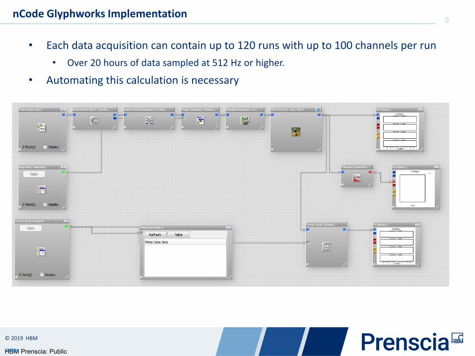
9
• Each data acquisition can contain up to 120 runs with up to 100 channels per run• Over 20 hours of data sampled at 512 Hz or higher.
• Automating this calculation is necessary
nCode Glyphworks Implementation

HBM Prenscia: Public
© 2019 HBM
Public
10
• Step 0: Define the coordinate geometry• Location of the transducers used for measuring acceleration on the rigid body• Defined from physical measurements or CAD models
• An Excel macro generates a .xml metadata file containing the geometry data for each acceleration measurement being used for the rigid body motion calculation
nCode Glyphworks Implementation

HBM Prenscia: Public
© 2019 HBM
Public
11nCode Glyphworks Implementation
Raw time histories
Channels to be used for rigid body calculation
Metadata containing x,y,zcoordinates of transducers.
HBM Prenscia: Public
© 2019 HBM
Public
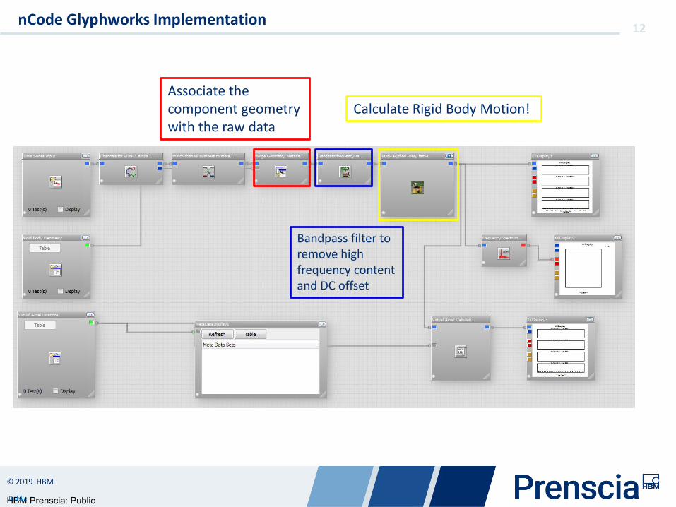
12nCode Glyphworks Implementation
Associate the component geometry with the raw data
Calculate Rigid Body Motion!
Bandpass filter to remove high frequency content and DC offset

HBM Prenscia: Public
© 2019 HBM
Public
13
• Written with the Python Scripting Glyph
• Originally developed in MATLAB• LAPack is LAPack
• Python does not require a license
• Buffered processing for speed• np.pinv() for numerical stability
• Can accept an arbitrary number of channels and accelerometer orientations
nCode Glyphworks Implementation

HBM Prenscia: Public
© 2019 HBM
Public
14
• If we are able to accurately estimate the rigid body accelerations, then acceleration at any point on the body can be calculated too.
𝑎𝑎𝑣𝑣 = 𝑎𝑎𝑐𝑐 + 𝛼𝛼 × 𝑟𝑟𝑐𝑐𝑛𝑛
• DANGER! This method will not include motion due to local deflection or excitation!• Local bending mode• Powertrain excitation / forced response
Use Cases - Virtual Accelerometers
EstimatedKnown from component geometry

HBM Prenscia: Public
© 2019 HBM
Public
15
• Measurements from 4 triaxial accelerometers at the engine mount locations were used for this calculation
• A 5th triax was installed on the top of the flywheel housing in between the engine and the transmission.
• This triax was not used for the rigid body motion calculation. • A virtual acceleration calculation was performed for the flywheel housing
accelerometer using the rigid body motion estimates from the engine mount measurements.
• The results are plotted in the following slides.
6DoF Peformance

HBM Prenscia: Public
© 2019 HBM
Public
166DoF Performance
Calculated using 6DoF and Virtual Acceleration
Measured
HBM Prenscia: Public
© 2019 HBM
Public
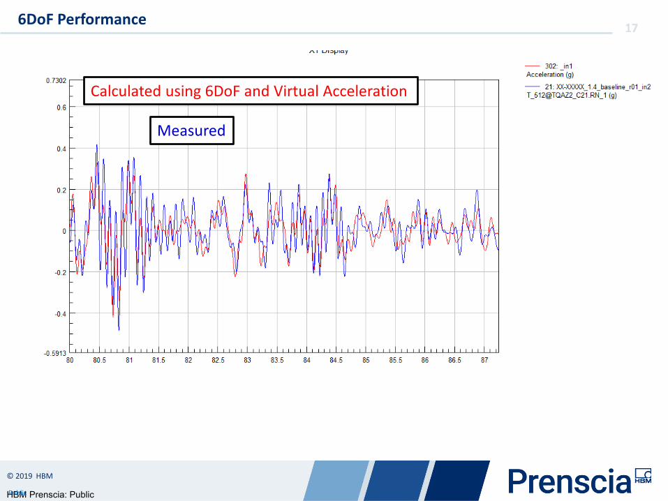
176DoF Performance
Calculated using 6DoF and Virtual Acceleration
Measured

HBM Prenscia: Public
© 2019 HBM
Public
186DoF Performance
Pretty good
Calculated using 6DoF and Virtual Acceleration
Measured

HBM Prenscia: Public
© 2019 HBM
Public
196DoF Performance
Correct frequency content, but amplitudes are a bit low…
Calculated using 6DoF and Virtual Acceleration
Measured
HBM Prenscia: Public
© 2019 HBM
Public
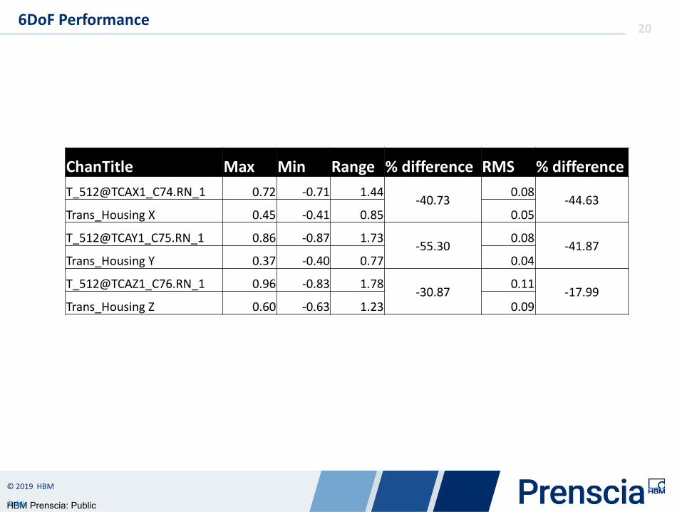
206DoF Performance
ChanTitle Max Min Range % difference RMS % differenceT_512@TCAX1_C74.RN_1 0.72 -0.71 1.44 -40.73 0.08 -44.63Trans_Housing X 0.45 -0.41 0.85 0.05
T_512@TCAY1_C75.RN_1 0.86 -0.87 1.73 -55.30 0.08 -41.87Trans_Housing Y 0.37 -0.40 0.77 0.04
T_512@TCAZ1_C76.RN_1 0.96 -0.83 1.78 -30.87 0.11 -17.99Trans_Housing Z 0.60 -0.63 1.23 0.09

HBM Prenscia: Public
© 2019 HBM
Public
21Use Cases – Powertrain Motion Design Iterations

HBM Prenscia: Public
© 2019 HBM
Public
22Use Cases – Cab Motion

HBM Prenscia: Public
© 2019 HBM
Public
23
• Estimated Powertrain 6DoF from accelerometer measurements to identify coupling between axle motion and powertrain rigid body modes.
Use Cases – Wobble
Powertrain Roll/Yaw response lags the axle input by about 90 Degrees which is indicative of a driven resonance.
HBM Prenscia: Public
© 2019 HBM
Public
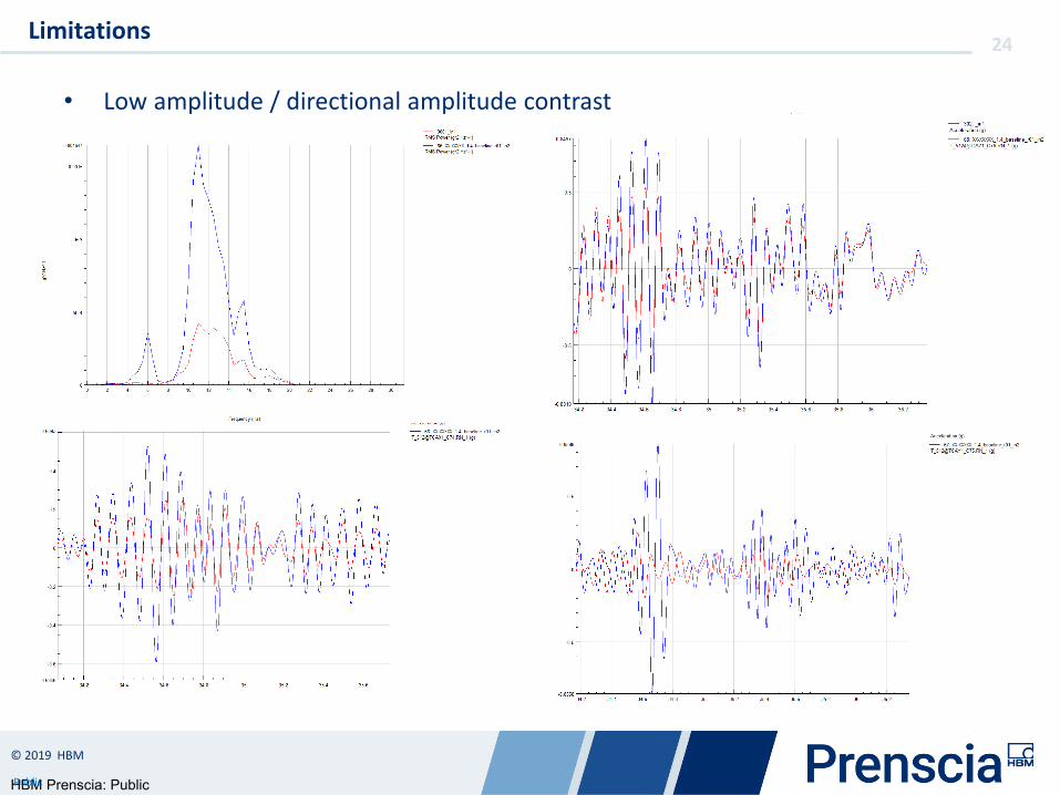
24
• Low amplitude / directional amplitude contrast
Limitations

HBM Prenscia: Public
© 2019 HBM
Public
25
Challenge Solution
Summary
Results
Determine the rigid body motion of vehicle components such as powertrain, cab, cooling module, etc.
Using some basic dynamics, linear algebra and python programming, this can be added to our standard data reduction processes in nCode.
More fundamental information regarding the performance of suspension systems can be determined in roughly the same amount of time

HBM Prenscia: Public
© 2019 HBM
Public
www.hbmprenscia.com


![GB - Triax Fibre Optic System [2009]](https://img.pdfslide.us/doc/110x75/577d214e1a28ab4e1e94eca8/gb-triax-fibre-optic-system-2009.jpg)