Embed Size (px)
Citation preview
Estimating Finger Contact Location and Object Pose from Contact
Measurements in 3-D Grasping
S. Haidacher and G. Hirzinger
German Aerospace Center - DLRInstitute for Robotics and Mechatronics
E-mail: [email protected]
Abstract — Autonomously grasping a predefinedobject is a topic of recent research in the field of ser-vice robotics. On the one hand, there are numerousapproaches in the area of image processing concernedwith recognition and localization of this object. On theother hand, a lot of work has been done in the devel-opment of planning, approaching and grasping of theobject with a dextrous manipulator mounted on top ofa robot arm. However, in-between locating and grasp-ing, there are significant sources of uncertainty, e.g.estimation errors in image processing, errors in cali-bration of cameras and robot alone and with respect toeach other, and positioning errors in the robot control.During the critical closing phase of grasping however,visual servoing and position correction is almost im-possible to achieve due to obstruction of the object bythe gripper. This paper presents an algorithm to locallyestimate the position and orientation of the object tobe grasped from contact information and a geometricdescription of the object. In this scenario, an objectdescription is usually available to a sufficiently accu-rate extent from grasp planning.
1 Introduction
Figure 1: DLR Hand II grasping an object
In recent years, in the field of robotic grippers anddextrous manipulators, a lot of developments havebeen brought forward. A general overview can beobtained from [2]. On the side of the gripper hard-ware, highly sophisticated devices are available witha large amount of sensory information [6, 12] (cf. fig1). Based upon these, numerous algorithms have beenpresented to optimally plan [5], optimize and control[16] the grasp of a known or unknown object. Now,
in the field of service robotics, a system consisting ofa mobile platform, an arm and an adequate gripper,is to work in a more complex environment. A typi-cal task would be to detect an object of interest andlocalize it. Then a path for the approach of the armhas to be developed and the gripper positions for astable grasp have to be computed. Finally the ob-ject can be grasped [15, 4]. However, the quality androbustness of the approach path and the grasp itselfheavily relies on the accurateness of the localization ofthe object. The localization of the object however is inmost cases done using global optical sensors. Althoughgood for large scale path and grasp planing, these sen-sors wont render reliable values in the final phase ofattaching the fingers to the object, because object orfingers may be obstructed from vision. To solve thisproblem, researchers propose object recognition andpose estimation using local sensors. Both steps aretreated separately as recognizing before locating or inone step by recognizing while locating (cf. [9]). Anearly approach in the first group is given in [8], wherecontact features from a LSHGC description of objectsare used to estimated pose of an object using tactilesensors. In [7] objects are examined using EPM mod-els built up during tactile exploration. In the lattergroup, [9] uses a Kalman filter to determine the poseof a geometrically modeled object from an ultrasonicor infrared sensor. In [13] an unknown object is implic-itly located and guided along a desired trajectory usingtactile feedback. The approach taken in [11] observesan object in motion for pose estimation. [1] describesa system to combine visual and tactile sensing. Theseapproaches all use either tactile information or visualsensing. Algorithms to exploit other sensory informa-tion rendering exteroceptive contact information, e.g.the position of contact and the direction of the sur-face normal of the finger and object surface in theircommon contact point are given in [3, 10].
This paper presents a blind man’s approach tograsping. After blindly approaching an object, fingermeasurements are compared with a previously gener-ated model. From this, by examining characteristics ofthe grasp and the object, hypotheses are generated forpossible contact points of the fingers with the object.
Proceedings of the 2003 IEEE International Conference on Robotics & Automation Taipei, Taiwan, September 14-19, 2003
0-7803-7736-2/03/$17.00 ©2003 IEEE 1805
The hypotheses are tested by finding a position andorientation of the grasped item relative to the gripper,that best complies with given measurements. Thus,this algorithm primarily implements the second stepin recognizing before locating. Although theoreticallyworking totally blindly, its main intention is to en-hance the capabilities of other localization systems bygiving more local information. This is helpful whenthese other systems are obstructed by scene objects asother items or a robotic arm or when a sufficient, ab-solute calibration between the location of the gripperand the localization system can not be obtained for ex-ample due to elasticity of the arm holding the gripper.In contrast to other algorithms for object localizationknown for example in the graphics and image process-ing community, the work presented here relies on theextremely sparse measurement of n fingers touching anobject only once. On the side of the gripper, the mea-surements used to examine contact are either tactilereadings from the finger tip or other information al-lowing determination of the contact point between thegripper and the grasped item. On the side of the ob-ject, no complete object description is required, sincethis approach is intended for local pose estimation.The model has to contain only those parts possiblyencountered during grasping. In order to increase theperformance of the algorithm, it is split into two parts,an offline refinement of the model and a online processsetting up and testing contact hypotheses and estimat-ing the object’s orientation. This paper is structuredas follows: The modeling is described in section 2. Therefinement of the model and the determination of hy-potheses is presented in sections 3.1 and 3.2 respec-tively. The test of hypotheses is described in section4. Finally results of simulations and experiments areshown in section 5. In terms of notation, in this pa-per, superscripts 3(x) refer to the coordinate systemS(x), subscripts 3o and 3c refer to object and contactquantities respectively, i and j refer to fingers, k andl to facets.
2 Modeling an Object
Most grippers available are capable of deliveringcontact information in one way or another. With afinger i contacting an object, detection of the point
of contact x(w)c,i in the world reference frame S(w) and
the direction of the normal vector n(w)c,i of the finger
surface at this point can be achieved in one of twoways. Either tactile sensor information [14] can beused or appropriate algorithms [3, 10] may be appliedto obtain this data from other sources of exteroceptivecontact information as for example joint torques or fin-ger velocities while moving over an object’s surface. Ingraphics, this measurement is termed oriented point.It describes the tangential plane at the point of con-
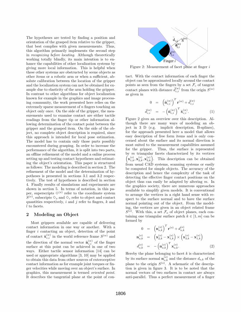
Figure 2: Measurement of facet plane at finger i
tact. With the contact information of each finger theobject can be approximated locally around the contactpoints as seen from the fingers by a set Fc of tangent
contact planes with distance d(w)c,i from the origin S(w)
as given in
0 =(
n(w)c,i
)T
r(w) + d(w)c,i
d(w)c,i = −
(
n(w)c,i
)T
x(w)c,i . (1)
Figure 2 gives an overview over this description. Al-though there are many ways of modeling an ob-ject in 3 D (e.g. implicit description, B-splines),for the approach presented here a model that allowseasy description of free form items and is only con-cerned about the surface and its normal direction ismost suited to the measurement capabilities assumedfor the gripper. Thus, the surface is representedby m triangular facets characterized by its vertices(
x(o)1,k,x
(o)2,k,x
(o)3,k
)
. This description can be obtained
from usual CAD systems, scanning systems or easilybe computed for simple objects. The accuracy of thedescription and hence the complexity of the task ofdetecting the effective finger contact positions on theobject thus can easily be adapted by altering m. Inthe graphics society, there are numerous approachesavailable to simplify given models. It is conventionalto arrange the vertices in a right hand sense with re-spect to the surface normal and to have the surfacenormal pointing out of the object. From the model-ing, the vertices are given in an object related frameS(o). With this, a set Fo of object planes, each con-taining one triangular surface patch k ∈ [1,m] can beformed by
0 =(
n(o)o,k
)T
r(o) + d(o)o,k
n(o)o,k =
(
x(o)2,k − x
(o)1,k
)
×(
x(o)3,k − x
(o)1,k
)
d(o)o,k = −
(
n(o)o,k
)T
x(o)o,k. (2)
Hereby the plane belonging to facet k is characterized
by its surface normal n(o)o,k and the distance do,k of the
plane to the origin S(o). A schematic of the descrip-tion is given in figure 3. It is to be noted that thenormal vectors of two surfaces in contact are alwaysanti-parallel. Thus a perfect measurement of a finger
1806
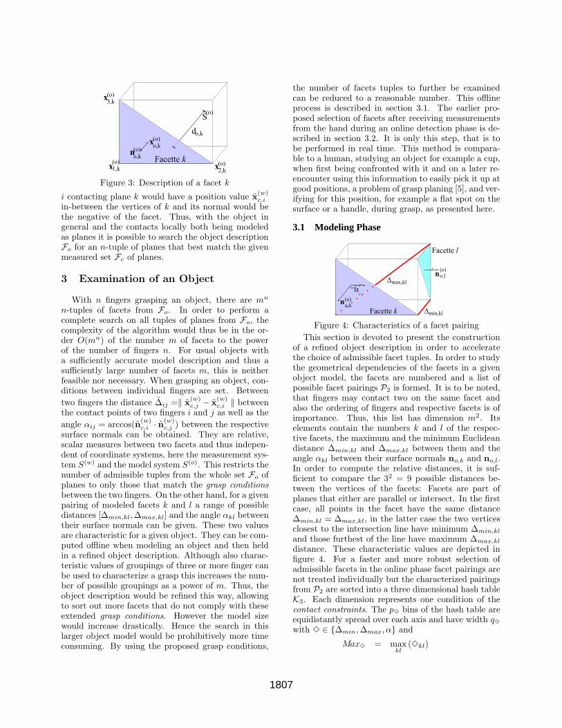
Figure 3: Description of a facet k
i contacting plane k would have a position value x(w)c,i
in-between the vertices of k and its normal would bethe negative of the facet. Thus, with the object ingeneral and the contacts locally both being modeledas planes it is possible to search the object descriptionFo for an n-tuple of planes that best match the givenmeasured set Fc of planes.
3 Examination of an Object
With n fingers grasping an object, there are mn
n-tuples of facets from Fo. In order to perform acomplete search on all tuples of planes from Fo, thecomplexity of the algorithm would thus be in the or-der O(mn) of the number m of facets to the powerof the number of fingers n. For usual objects witha sufficiently accurate model description and thus asufficiently large number of facets m, this is neitherfeasible nor necessary. When grasping an object, con-ditions between individual fingers are set. Between
two fingers the distance ∆ij =‖ x(w)c,j − x
(w)c,i ‖ between
the contact points of two fingers i and j as well as the
angle αij = arccos(n(w)c,i · n
(w)c,j ) between the respective
surface normals can be obtained. They are relative,scalar measures between two facets and thus indepen-dent of coordinate systems, here the measurement sys-tem S(w) and the model system S(o). This restricts thenumber of admissible tuples from the whole set Fo ofplanes to only those that match the grasp conditionsbetween the two fingers. On the other hand, for a givenpairing of modeled facets k and l a range of possibledistances [∆min,kl,∆max,kl] and the angle αkl betweentheir surface normals can be given. These two valuesare characteristic for a given object. They can be com-puted offline when modeling an object and then heldin a refined object description. Although also charac-teristic values of groupings of three or more finger canbe used to characterize a grasp this increases the num-ber of possible groupings as a power of m. Thus, theobject description would be refined this way, allowingto sort out more facets that do not comply with theseextended grasp conditions. However the model sizewould increase drastically. Hence the search in thislarger object model would be prohibitively more timeconsuming. By using the proposed grasp conditions,
the number of facets tuples to further be examinedcan be reduced to a reasonable number. This offlineprocess is described in section 3.1. The earlier pro-posed selection of facets after receiving measurementsfrom the hand during an online detection phase is de-scribed in section 3.2. It is only this step, that is tobe performed in real time. This method is compara-ble to a human, studying an object for example a cup,when first being confronted with it and on a later re-encounter using this information to easily pick it up atgood positions, a problem of grasp planing [5], and ver-ifying for this position, for example a flat spot on thesurface or a handle, during grasp, as presented here.
3.1 Modeling Phase
Figure 4: Characteristics of a facet pairing
This section is devoted to present the constructionof a refined object description in order to acceleratethe choice of admissible facet tuples. In order to studythe geometrical dependencies of the facets in a givenobject model, the facets are numbered and a list ofpossible facet pairings P2 is formed. It is to be noted,that fingers may contact two on the same facet andalso the ordering of fingers and respective facets is ofimportance. Thus, this list has dimension m2. Itselements contain the numbers k and l of the respec-tive facets, the maximum and the minimum Euclideandistance ∆min,kl and ∆max,kl between them and theangle αkl between their surface normals no,k and no,l.In order to compute the relative distances, it is suf-ficient to compare the 32 = 9 possible distances be-tween the vertices of the facets: Facets are part ofplanes that either are parallel or intersect. In the firstcase, all points in the facet have the same distance∆min,kl = ∆max,kl, in the latter case the two verticesclosest to the intersection line have minimum ∆min,kl
and those furthest of the line have maximum ∆max,kl
distance. These characteristic values are depicted infigure 4. For a faster and more robust selection ofadmissible facets in the online phase facet pairings arenot treated individually but the characterized pairingsfrom P2 are sorted into a three dimensional hash tableK3. Each dimension represents one condition of thecontact constraints. The p3 bins of the hash table areequidistantly spread over each axis and have width q3
with 3 ∈ {∆min,∆max, α} and
Max3 = maxkl(3kl)
1807
Min3 = minkl(3kl)
q3 =Max3 −Min3
p3
. (3)
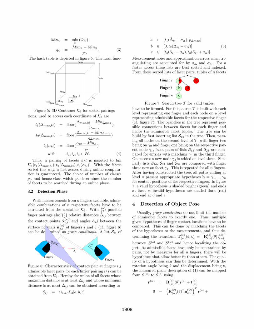
The hash table is depicted in figure 5. The hash func-
Figure 5: 3D Container K3 for sorted pairings
tions, used to access each coordinate of K3 are
t1(∆max,kl) = floor(∆max,kl −Min∆max
q∆max
)
t2(∆min,kl) = floor(∆min,kl −Min∆min
q∆min
)
t3(αkl) = floor(αkl −Minα
qα
)
with t1, t2, t3 ∈ IN. (4)
Thus, a pairing of facets k/l is inserted to binK3 [t1(∆max,kl), t2(∆min,kl), t3(αkl)]. With the facetssorted this way, a fast access during online computa-tion is guaranteed. The choice of number of classesp3 and hence class width q3 determines the numberof facets to be searched during an online phase.
3.2 Detection Phase
With measurements from n fingers available, admis-sible combinations of n respective facets have to beextracted from the container K3. With
(
n2
)
possible
finger pairings also(
n2
)
relative distances ∆ij between
the contact points x(w)c,i and angles αij between the
surface normals n(w)c,i of fingers i and j (cf. figure 6)
can be determined as grasp conditions. A list Sij of
Figure 6: Characteristics of contact pair at fingers i,j
admissible facet pairs for each finger pairing i/j can beobtained from K3. Hereby the union of all facets whosemaximum distance is at least ∆ij and whose minimum
distance is at most ∆ij can be obtained according to
Sij = ∩a,b,cK3[a, b, c]
a ∈ [t1(∆ij − σ∆), p∆max]
b ∈ [0, t2(∆ij + σ∆)] (5)
c ∈ [t3(αij − σα), t3(αij + σα)].
Measurement noise and approximation errors when tri-angulating are accounted for by σ∆ and σα. For afaster access these lists are best sorted and indexed.From these sorted lists of facet pairs, tuples of n facets
Figure 7: Search tree T for valid tuples
have to be formed. For this, a tree T is built with eachlevel representing one finger and each node on a levelrepresenting admissible facets for the respective finger(cf. figure 7). The branches in the tree represent pos-sible connections between facets for each finger andhence the admissible facet tuples. The tree can bebuild by first inserting list S12 in the tree. Then, pars-ing all nodes on the second level of T , with finger twobeing on γ2 and finger one being on the respective par-ent node γ1, facet pairs of lists S13 and S23 are com-pared for entries with matching γ3 in the third finger.On success a new node γ3 is added on level three. Sim-ilarly lists S14, S24 and S34 are compared with fingerthree now on facet γ3. This is repeated for all n fingers.After having constructed the tree, all paths ending atlevel n present appropriate hypotheses h = γ1, ..., γn
for contact positions of the respective fingers. In figure7, a valid hypothesis is shaded bright (green) and endsat facet c, invalid hypotheses are shaded dark (red)and end at d and e.
4 Detection of Object Pose
Usually, grasp constraints do not limit the numberof admissible facets to exactly one. Thus, multiplegiven hypotheses of finger contact locations have to becompared. This can be done by matching the facetsof the hypotheses to the measurements, and thus de-
termining the transform T(o)(w)(θ, t) =
[
R(o)(w)(θ)t
(o)(w)
]
between S(o) and S(w) and hence localizing the ob-ject. As admissible facets have only be constrained bypairs, not by measures for all n fingers, there will behypotheses that allow better fit than others. The qual-ity of a hypothesis can thus be determined. With therotation angle being θ and the displacement being t,the measured plane description of (1) can be mappedfrom S(w) to S(o) using
r(w) = R(o)(w)(θ)r
(o) + t(o)(w)
0 =(
R(o)(w)(θ)
T n(w)c,i
)T
r(o) +
1808
(
(
n(w)c,i
)T
· t(o)(w) + d
(w)c,i
)
. (6)
With this, an error function L can be developed which
compares n(o)c,i and d
(o)c,i of the measured contact plane
to n(o)o,k and d
(o)o,k of the respective object facet:
L(θ, t) =n∑
i=1
{
‖R(o)(w)(θ)
T n(w)c,i −
(
−n(o)o,k
)
‖2 +
(
n(w)Tc,i · t
(o)(w) + d
(w)c,i −
(
−n(o)o,k
))2}
.(7)
The negative sign in front of model values originatesin the opposing directions of the normal vectors onthe object and the contacting finger tip. This func-tion L, computes the secant in the unit circle betweenthe two normal vectors and the difference between thedistances to the origin along the respective surface nor-mal. A lateral displacement within the tangent planecannot be measured and is hence not penalized. Min-imizing Lmin,h = minθ,t L(θ, t) renders an estimate ofthe position topt and orientation θopt of the object with
respect to S(w). Thus by testing for all h it is possibleto choose the best fitting tuple of facets provided themeasurements are accurate. Any previous measure-ment from vision or similar is taken into account asstarting value. The optimization can be done using astandard Levenberg-Marquard algorithm.
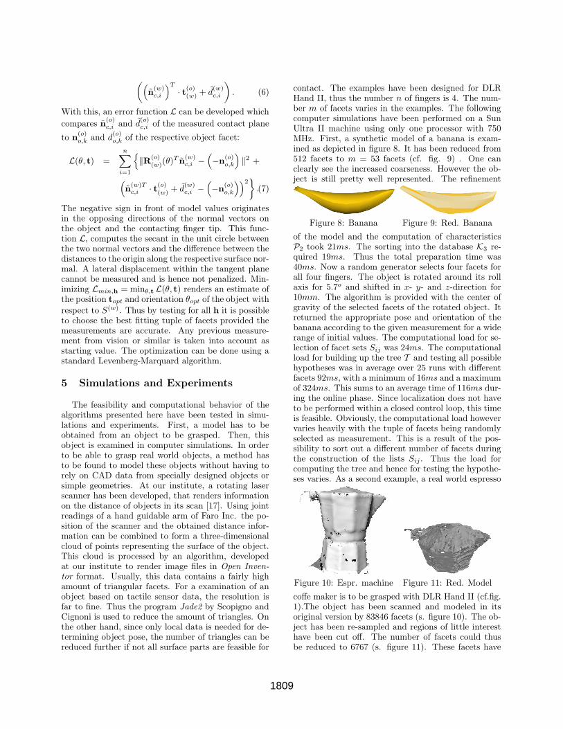
5 Simulations and Experiments
The feasibility and computational behavior of thealgorithms presented here have been tested in simu-lations and experiments. First, a model has to beobtained from an object to be grasped. Then, thisobject is examined in computer simulations. In orderto be able to grasp real world objects, a method hasto be found to model these objects without having torely on CAD data from specially designed objects orsimple geometries. At our institute, a rotating laserscanner has been developed, that renders informationon the distance of objects in its scan [17]. Using jointreadings of a hand guidable arm of Faro Inc. the po-sition of the scanner and the obtained distance infor-mation can be combined to form a three-dimensionalcloud of points representing the surface of the object.This cloud is processed by an algorithm, developedat our institute to render image files in Open Inven-tor format. Usually, this data contains a fairly highamount of triangular facets. For a examination of anobject based on tactile sensor data, the resolution isfar to fine. Thus the program Jade2 by Scopigno andCignoni is used to reduce the amount of triangles. Onthe other hand, since only local data is needed for de-termining object pose, the number of triangles can bereduced further if not all surface parts are feasible for
contact. The examples have been designed for DLRHand II, thus the number n of fingers is 4. The num-ber m of facets varies in the examples. The followingcomputer simulations have been performed on a SunUltra II machine using only one processor with 750MHz. First, a synthetic model of a banana is exam-ined as depicted in figure 8. It has been reduced from512 facets to m = 53 facets (cf. fig. 9) . One canclearly see the increased coarseness. However the ob-ject is still pretty well represented. The refinement
Figure 8: Banana Figure 9: Red. Banana
of the model and the computation of characteristicsP2 took 21ms. The sorting into the database K3 re-quired 19ms. Thus the total preparation time was40ms. Now a random generator selects four facets forall four fingers. The object is rotated around its rollaxis for 5.7o and shifted in x- y- and z-direction for10mm. The algorithm is provided with the center ofgravity of the selected facets of the rotated object. Itreturned the appropriate pose and orientation of thebanana according to the given measurement for a widerange of initial values. The computational load for se-lection of facet sets Sij was 24ms. The computationalload for building up the tree T and testing all possiblehypotheses was in average over 25 runs with differentfacets 92ms, with a minimum of 16ms and a maximumof 324ms. This sums to an average time of 116ms dur-ing the online phase. Since localization does not haveto be performed within a closed control loop, this timeis feasible. Obviously, the computational load howevervaries heavily with the tuple of facets being randomlyselected as measurement. This is a result of the pos-sibility to sort out a different number of facets duringthe construction of the lists Sij . Thus the load forcomputing the tree and hence for testing the hypothe-ses varies. As a second example, a real world espresso
Figure 10: Espr. machine Figure 11: Red. Model
coffe maker is to be grasped with DLR Hand II (cf.fig.1).The object has been scanned and modeled in itsoriginal version by 83846 facets (s. figure 10). The ob-ject has been re-sampled and regions of little interesthave been cut off. The number of facets could thusbe reduced to 6767 (s. figure 11). These facets have
1809
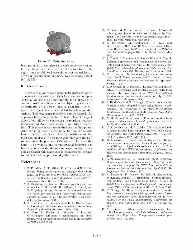
Figure 12: Estimated Grasp
been provided to the algorithm with some restrictionsfor each finger in order to reduce the search time. Thealgorithm was able to locate the object regardeless oferrors in measurement and model to a satisfying extent(cf. fig 12)
6 Conclusion
In order to allow robotic grippers to grasp real worldobjects with uncertainty in their location, we here pre-sented an approach to determine the most likely set ofcontact positions of fingers on the object together withan estimate of the objects pose as seen from the fin-gers. The object has been modeled by a triangulatedsurface. This way general surfaces can be treated. Anapproach has been presented to first refine the objectdescription offline by characteristic relations betweenits facets and store those values in an object descrip-tion. This allows faster access during an online phase.After receiving tactile measurements from the robotichand, this database is searched for possible matchingfacet combinations. These facet combinations are usedto determine the position of the object relative to thehand. The validity and computational behavior hasbeen examined in simulations and experiments. In on-going research this algorithm is enhanced to increaserobustness and computational performance.
References
[1] P. K. Allen, A. T. Miller, P. Y. Oh, and B. S. Lei-bowitz. Using tactile and visual sensing with a robotichand. In Proceedings of the IEEE International Con-
ference on Robotics and Automation, April 1997, Al-
buquerque, New Mexico, 1997.[2] A. Bicchi and V. Kumar. Robotic grasping and ma-nipulation. In S. Nicosia, B. Siciliano, A. Bicchi, andP. V. (eds.), editors, Ramsete: Articulated and mo-
bile robots for services and Technology, volume 270,chapter 4, pages 55–74. Springer-Verlag, Berlin Hei-delberg, Germany, 2001. .
[3] A. Bicchi, J. K. Salisbury, and D. L. Brock. Con-tact sensing from force measurements. International
Journal of Robotics Research, 12(3), 1993.[4] C. Borst, M. Fischer, S. Haidacher, H. Liu, andG. Hirzinger. Dlr hand ii: Experiments and expe-riences with an anthropomorphic hand. In submitted
to ICRA 2003, 2003.
[5] C. Borst, M. Fischer, and G. Hirzinger. A fast androbust grasp planner for arbitrary 3d objects. In Proc.
IEEE Conf. on Robotics and Automation, pages 1890–1896, Detroit, Michigan, May 1999. .
[6] J. Butterfass, M. Grebenstein, H. Liu, andG. Hirzinger. DLR-Hand II: Next Generation of Dex-trous Robot Hand. In Proc. IEEE Conf. on Robotics
and Automation, pages 109 – 114, Seoul, Korea, May2001. .
[7] S. Caselli, C. Magnanini, F. Zanichelli, and E. Caraffi.Efficient exploration and recognition of convex ob-jects based on haptic perception. In Proceedings of the
IEEE International Conference on Robotics and Au-
tomation, April 1996, Minneapolis, Minnesota, 1996.[8] R. S. Fearing. Tactile sensing for shape interpreta-tion. In S. Venkataraman and T. Iberall, editors,Dextrous Robot Manipulation, chapter 10. Springer-Verlag, 1990.
[9] J. D. Geeter, H. V. Brussel, J. D. Schutter, and M. De-crton. Recognizing and locating objects with localsensors. In Proceedings of the IEEE International
Conference on Robotics and Automation, April 1996,
Minneapolis, Minnesota, 1996.[10] S. Haidacher and G. Hirzinger. Contact point identi-
fication in multi-fingered grasps using kinematic con-straints. In Proceedings of the IEEE International
Conference on Robotics and Automation May 2002,
Washington,D.C. ,USA, 2002.[11] Y. B. Jia and M. Erdmann. Pose and motion from
contact. International Journal of Robotics Research,18(5):466 – 490, May 1999.
[12] C. S. Lovchik and M. A. Diftler. The robonaut hand:A dextrous robot hand for space. In Proc. IEEE Conf.
on Robotics and Automation, pages 907 – 912, De-troit, Michigan, USA, May 1999.
[13] H. Maekawa, K. Tanie, and K. Komoriya. Tactilesensor based manipulation of an unknown object bya multifingered hand with rolling contact. In Pro-
ceedings of the IEEE International Conference on
Robotics and Automation, May 1995, Nagoya, Japan,1995.
[14] A. M. Okamura, M. L. Turner, and M. R. Cutkosky.Haptic exploration of objects with rolling and slid-ing. In Proceedings of the IEEE International Con-
ference on Robotics and Automation, April 1997, Al-
buquerque, New Mexico, 1997.[15] L. Petersson, P. Jensfelt, D. Tell, M. Strandberg,
D. Kragic, and H. I. Christensen. System Integra-tion for Real-World Manipulation Tasks. In Proc. of
IEEE Intl. Conference on Robotics and Automation,pages 2500 – 2505, Washington DC, USA, May 2002.
[16] T. Schlegl, M. Buss, T. Omata, and G. Schmidt.Fast dextrous regrasping with optimal contact forcesand contact sensor-based impedance control. In Pro-
ceedings of the IEEE International Conference on
Robotics and Automation May 2001, Seoul ,Korea,2001.
[17] M. Suppa. Miniaturisierter laserscanner fuerrobotikanwendungen. Mechatronik-News, Informa-
tionen des Bayrischen Kompetenznetzwerkes fuer
Mechatronik, (1), 2002.
1810