Embed Size (px)
Citation preview
8/8/2019 Estimating Circuit Models for a Deep-bar Induction Motor Using Time Harmonic Finite Element Analysis
http://slidepdf.com/reader/full/estimating-circuit-models-for-a-deep-bar-induction-motor-using-time-harmonic 1/8
APPENDIX B
Publication P3
Repo A.-K., Niemenmaa A., Arkkio A. Estimating circuit models for a deep-bar induction
motor using time harmonic finite element analysis. Proceedings – International Conference
in Electrical Machines, Crete, Greece, September 2006, No. 614, 6 p.
© 2006 Anna-Kaisa Repo, Asko Niemenmaa, and Antero Arkkio
105

8/8/2019 Estimating Circuit Models for a Deep-bar Induction Motor Using Time Harmonic Finite Element Analysis
http://slidepdf.com/reader/full/estimating-circuit-models-for-a-deep-bar-induction-motor-using-time-harmonic 2/8
106

8/8/2019 Estimating Circuit Models for a Deep-bar Induction Motor Using Time Harmonic Finite Element Analysis
http://slidepdf.com/reader/full/estimating-circuit-models-for-a-deep-bar-induction-motor-using-time-harmonic 3/8
614 1
Abstract —A method for estimating equivalent circuit models
for deep-bar induction motor is presented. The method is based
on the time-harmonic finite element analysis (FEA). The
parameters of the studied motor depend strongly on the
frequency and a single-cage equivalent circuit with constantparameters predicts the torque only at the same operation point
where the parameters are defined. In the presented paper, the
rotor is modelled with multiple branches and the same circuit
model is capable of depicting a wider operation range of the
motor.
Index Terms —finite element analysis, parameter estimation,
equivalent circuit models
I. I NTRODUCTIO N
HE time-stepping finite-element analysis is accurate
and widely applied method in the study and simulation of
electrical machines. Electrical machines usually operate in
connection with control circuits, power electronics,
components of electrical grid and mechanics causing a
complex interaction. The computation capacity often limits the
use of comprehensive models, and a simpler analytical model
for the machine is required in many applications.
The basic single-cage equivalent circuit model with
constant parameters is able to model the behaviour of the
machine only at certain operation point. Because of the skin
effect in the rotor bars, the parameters of the circuit model
depend on the frequency. The values for the rotor resistance
and leakage inductance var y the most. Several proposals have
been made in order to include the skin effect into the circuitmodel, for example [1], [2]. Usually one or more additional
rotor branches are included into the basic model, while the
physical interpretation for the parameters is still preser ved.
In the proposed paper, a systematic method for extracting
the equivalent circuit parameters from the two-dimensional
time-harmonic FEA is presented. For the analytical model, the
number of additional branches can be chosen depending on
the requirements of the application.
The authors are with the Laborator y of Electromechanics, Helsinki
University of Technology, FI-02015 TKK, Finland (email: [email protected]; [email protected]; [email protected])
II. METHOD OF A NALYSIS
A. Two-dimensional time-harmonic model
A radial-f lux cage induction motor is studied assuming a
two-dimensional magnetic vector potential A and current
density J
( , , )
( , , )
z
z
A x y t
J x y t
=
=
e
e
A
J . (1)
The z -axis is in the direction of the shaft of the machine.
Assuming sinusoidal time variation, phasor variables are used
for the field solution. The stator frequency is equal to the
supply frequency ω s. The rotor frequency is the slip frequency
sω s. The rotor is stationar y, i.e. the effects of motion are
modelled by assuming the slip frequency in the rotor, only.
After these assumptions, the equation for the magnetic vector
potential is
eff ( )ν ∇× ∇× = A J (2)
where ν eff is an effective permeability [3] and A is the vector-
potential phasor. This two-dimensional time-harmonic model
can be used for the core region of a radial-f lux machine but it
does not model proper ly the magnetic field or winding
connections in the end-winding space. The end effects are
taken into account approximately by coupling the field
equation with the circuit equations of the windings and using
end-winding impedances. Winding currents or potentials or
both of them are used as additional variables. For instance, the
circuit equation for a stator phase is
( )ni
s s s nin n n n ninii
= j +j dS
N u R L iS
ω ω β + ⋅ A S
(3)
where Rns and Ln
s are the resistance and end-winding
inductance of the nth phase. The summation over i includes all
the coil sides of phase n. Variable β ni = ±1 defines whether a
positive or negative coil side is considered. N ni is the number
of turns and S ni the cross-sectional are of coil side i. is the
core length of the machine. The details of combining the field
and circuit equations have been discussed among others in
references [4]-[6]. A finite element method is used to solve the
field and circuit variables numerically.
Estimating circuit models for a deep-bar
induction motor using time harmonic finiteelement analysis
Anna-Kaisa Repo, Asko Niemenmaa, and Antero Arkkio
T
107

8/8/2019 Estimating Circuit Models for a Deep-bar Induction Motor Using Time Harmonic Finite Element Analysis
http://slidepdf.com/reader/full/estimating-circuit-models-for-a-deep-bar-induction-motor-using-time-harmonic 4/8
614 2
B. Impedance matrix
The aim is to present the circuit equations of the machine in
matrix form
=u Zi (4)
The dimensions of the impedance matrix Z
are(m+Qr )×(m+Qr ), where m is the number of phases and Qr the
number of rotor bars. u is a voltage vector and i a current
vector. The electromagnetic couplings between the windings
can be uniquely defined only for a linear system. The
linearization is done by solving the magnetic field in a chosen
operation point and freezing the permeability of the iron core
to this solution. Any of the field-circuit formulations referred
to in Section II.A can be used to solve the linearization field.
The coupling impedances are obtained by inserting a
current one by one in each phase winding and rotor bar and
computing the voltages produced by this current in all the
windings and bars. The current density in (2) must be
expressed as a function of the total current. For instance, acurrent ik in rotor bar k generates a magnetic vector potential
A according to equation
k
k
0 s s
k k
1( )+j j d = z z
S
i s s
S S ν ω σ ω σ ∇× ∇× − ⋅ A A A S e e (5)
where ν 0 is the linearised reluctivity, s the slip, ω the supply
frequency and S k the cross-sectional area of the bar. The
voltage induced in a stator phase winding is obtained from (3).
The voltage over rotor bar n is
n
n nk k s
n
= +j dS
u R i sS
ω ⋅ A S
(6)
where the Kronecker symbol δnk assures that a resistive term is present only if the current and voltage are associated with the
same conductor.
A element z nk of the impedance matrix Z is
nnk
k
u z
i= (7)
The rotor voltage equation (6) is not in proper form for the
impedance equation (4) as it does not include the voltages
induced at the ends of the rotor cage. The missing terms can
be taken into account by applying Kirchhoff’s laws to the
closed meshes of the cage. One possible method is discussed
in [6]. When applied, the voltage equation for the rotor
becomesr rs s rr re r ( ) 0= + + =M Mu Z i Z Z i . (8)
The elements of matrices Z rs and Z
rr are obtained from (6) and
(7). Matrix Z re is associated with the end-winding impedances
of the rotor cage. Matrix M transforms the bar voltages to
mesh voltages.
C. Equivalent circuit for a single-cage motor
Fig. 1 shows the conventional T equivalent circuit. It
represents the coupling between a stator phase current and a
somewhat fictitious rotor current.
Rs
Rr(s)
jX s
sjX
r
si
s
ir
i is r+
us jX
m
Fig. 1. Single-cage equivalent circuit model.
As there are two currents, the related coupling matrix Z has
dimensions 2×2. The approach of this study is to first compute
the large impedance matrix including all the couplings as
described in the previous section, and then reduce the large
matrix to a 2×2 matrix associated with Figure 1. A method
related to the symmetric components is used for the reduction.
If the stator winding has m phases and the rotor bars are taken
to form a poly-phase system with Qr phases, the positive
phase-sequence stator voltage, stator current and rotor currentare defined
r
r
2 (i -1) j
s s
i
i=1
2 ( i-1) j
s s
i
i=1
2 ( i-1) j
r r
i
i=1r
1e
1e
1e
m
m
m
m
u um
i im
i iQ
π
+
π
+
π
+
=
=
=
. (9)
The subscript + refers to the positive phase sequence. By
substituting the stator voltages from (4) in the first expression
of Eq. (9), the positive phase-sequence voltage is obtained as
a function of the phase and bar currentsr 2 (i-1) 2 (i-1)
j js ss s sr r
ik k ik k
i=1 k=1 i=1 k=1
1 1e e
Qm m m
m mu z i z im m
π π
+= + (10)
where z ssik refers to an element of the impedance matrix that
couples two stator windings and z sr ik to an element that couples
a stator winding to a rotor bar.
The first sum in (10) is taken to be the voltage induced by
the positive phase-sequence stator current and the second sum
the voltage induced by the positive phase-sequence rotor
current. Based on this assumption, the equation is written in a
simple scalar forms ss s sr r
u z i z i+ + +
= + (11)
where the impedances z ss and z sr are obtained by dividing the
sum containing the stator currents by is+ and the sum
containing the rotor currents by ir +
r
2(i-1) j
ss ss s
ik k si 1 k=1
2(i-1) j
sr sr r
ik k r i 1 k=1
1e
1e
m m
m
Qm
m
z z im i
z z im i
=+
=+
=
=
. (12)
The positive phase-sequence rotor voltage is calculated in a
similar manner as the stator voltage abover rs s rr r
0u w i w i+ + +
= + = (13)
108

8/8/2019 Estimating Circuit Models for a Deep-bar Induction Motor Using Time Harmonic Finite Element Analysis
http://slidepdf.com/reader/full/estimating-circuit-models-for-a-deep-bar-induction-motor-using-time-harmonic 5/8
614 3
The coefficients are
{ }
{ }
r
r r
2(i-1) j
rs rs s
k s ik i 1 k=1r
2(i-1) j
rr rr re r
k r ik i 1 k=1r
1e
1e
Q m
m
Q Q
m
w iQ i
w iQ i
=+
=+
=
= +
M
M
Z
Z Z
. (14)
Equations (11) and (13) define the relation between the
positive phase-sequence stator voltage and stator and rotor
currents. As the equations have been derived from the voltage
equations of two magnetically coupled poly-phase windings
having different phase numbers, the coupling coefficients z sr
and wrs are not equal. The equality is forced by rescaling (13)
( )sr
rs s rr r rs s rr r
rs0
z w i w i z i z i
w+ + + +
+ = + = (15)
wherers sr
sr rr rr
rs
z z
z z ww
=
= . (16)
Equations (11) and (15) define a simple equivalent circuit of
the single-cage induction motor. However, if leakage
reactances are preferred, the rotor quantities have to be
referred to the stator. A stator-referred rotor current f lowing in
the stator winding should induce a fundamental component of
the air-gap f lux that is equal to the fundamental component of
the f lux induced by the original rotor current. Using this
criterion, a reference coefficient κ is obtaineds 1 r
r 1 s
i
i
Φ κ
Φ +
+
= (17)
where Φ s1 and Φ r1 are the fundamental components of the air-
gap f luxes induced separately by the stator and rotor currents.
The f lux components are integrated from the air-gap vector
potential. The parameters referred to the stator and marked by
an apostrophe are
r r
+ +
ss ss
sr sr
rs rs
rr 2 rr
1'
'
'
'
'
i i
z z
z z
z z
z z
κ
κ
κ
κ
=
=
=
=
=
. (18)
The components of the equivalent circuit in Figure 1 are
obtained from the impedances referred to the stator
{ }
{ }
{ }
{ }
{ }
s ss
s ss sr
m sr
r rr rs
r rr
Re '
Im ' '
Im '
Im ' '
Re '
R z
X z z
X z
X z z
R z
σ
σ
=
= −
=
= −
=
. (19)
The linearization of the machine was done to a given
operation point. The circuit parameters obtained are, of
course, associated with the same operation point.
D. Multi-cage models
The method above can be generalised for a multi-cage
machine or to a model in which the deep bars are divided in
several sub-conductors. Such a division is shown in Fig. 2.
Fig. 2. Rotor bar is divided into three parts.
A positive phase-sequence rotor current is defined
separately for each of the sub-conductor layers. If three sub-
conductors per bar are used, the large impedance matrix is a
(m+3Qr )×(m+3Qr ) matrix, and (10), as an example, includes
one sum for the stator currents and three sums for the positive
phase-sequence sub-conductor currents. The reduction of the
large impedance matrix leads to a 4×4 coupling matrix. Each
rotor current is separately referred to the stator using (17). The
circuit equation for the three-cage induction machine is of the
form
=
ss
+11 12 13 14+
r1
21 22 23 24 +
r231 32 33 34
+
r341 42 43 44+
0
0
0
iZ Z Z Zu
Z Z Z Z i
Z Z Z Z i
Z Z Z Zi
. (20)
Again, the 4×4 coupling matrix represents an equivalent
circuit of the machine. However, multi-cage machines are
often modelled using a ladder-ty pe equivalent circuit. Such acircuit with three rotor branches is presented in Fig 3.
Zs Zc1 Zc2i
s
i i i is r1 r2 r3+ + + i
r1i
r2i
r3
us Zm Zr1 Zr2 Zr3
Fig. 3. Three-cage equivalent circuit model.
To fulfil Kirchhoff’s second law in the circuit of Fig. 3, the
coupling matrix should be of the form defined by (21) or at
least, it should be possible to transform the system of equations (20) so that a coupling matrix of ty pe (21) is
obtained. Obviously, this is not possible for a general case. A
4×4 matrix has 12 elements but there are only 7 coefficients
on the right hand side of (21). For the equality, the matrix on
the left hand side must be symmetric.
109
8/8/2019 Estimating Circuit Models for a Deep-bar Induction Motor Using Time Harmonic Finite Element Analysis
http://slidepdf.com/reader/full/estimating-circuit-models-for-a-deep-bar-induction-motor-using-time-harmonic 6/8
614 4
=
+ +
+
11 12 13 14
21 22 23 24 s
31 32 33 34
41 42 43 44
r1 r2
r3
1 0 0 0
0 0 0 0
0 0 0 0
0 0 0 0
0 0 0 0 0 0 0 0
0 1 0 0 0 0 0 0
0 0 0 0 0 0 1 0
0 0 0 0 0 0 0 0
0 0 0
Z Z Z Z
Z Z Z ZZ
Z Z Z Z
Z Z Z Z
Z Z
Z
+
+ +
m
c1 c2
0 1 1 1 1
0 0 0 0 1 1 1 1
0 0 0 0 1 1 1 1
0 0 0 1 1 1 1 1
0 0 0 0 0 0 0 0
0 1 1 1 0 0 0 0
0 1 1 1 0 0 1 1
0 1 1 1 0 0 1 1
Z
Z Z
(21)
Furthermore, the following constraints have to be fulfilled
= = = = = =
= = = = +
= = + +
m
12 13 14 21 31 41
m c1
23 24 32 42
m c1 c2
43 34
Z Z Z Z Z Z Z
Z Z Z Z Z Z
Z Z Z Z Z
(22)
The diagonal elements are
= +
= + +
= + + +
= + + +
s m
11
r1 m c1
22
r2 m c1 c2
33
r3 m c1 c2
44
Z Z Z
Z Z Z Z
Z Z Z Z Z
Z Z Z Z Z
(23)
If the coupling matrix fulfils these constraints, the
transformation to the ladder system is a straight for ward
process. If not, the ladder structure is too restrictive to
describe the machine. When the coupling matrix (20) is
constructed as described in Sections II-B–II-D, the conditions
(22) are met ver y well, and the ladder-circuit parameters give
almost exactly the same machine characteristics, i.e. stator
current and torque, as the original FEM solution. This
experience seems to apply for any division of the rotor bars to
sub-conductors. Possible problems are discussed in Chapter
IV.
III. R ESULTS
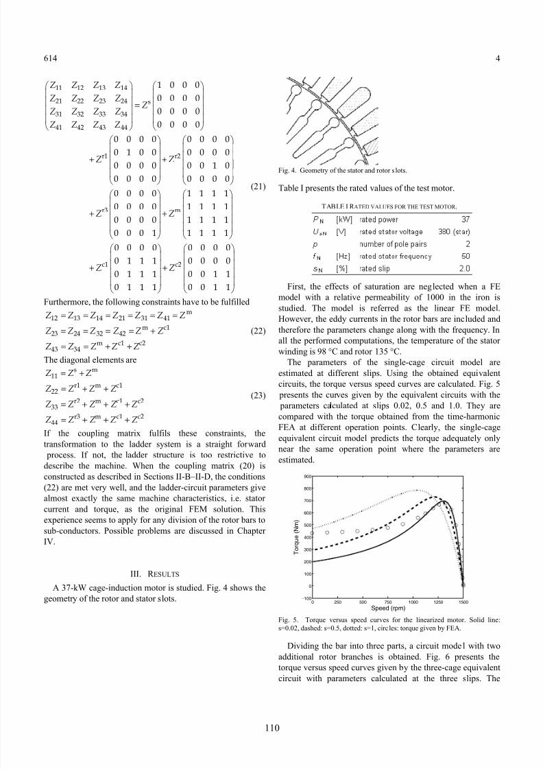
A 37-k W cage-induction motor is studied. Fig. 4 shows the
geometr y of the rotor and stator slots.
Fig. 4. Geometr y of the stator and rotor slots.
Table I presents the rated values of the test motor.
TABLE I R ATED VALUES FOR THE TEST MOTOR .
First, the effects of saturation are neglected when a FE
model with a relative permeability of 1000 in the iron is
studied. The model is referred as the linear FE model.
However, the eddy currents in the rotor bars are included and
therefore the parameters change along with the frequency. In
all the performed computations, the temperature of the stator
winding is 98 °C and rotor 135 °C.
The parameters of the single-cage circuit model are
estimated at different slips. Using the obtained equivalent
circuits, the torque versus speed cur ves are calculated. Fig. 5
presents the cur ves given by the equivalent circuits with the
parameters calculated at slips 0.02, 0.5 and 1.0. They arecompared with the torque obtained from the time-harmonic
FEA at different operation points. Clear ly, the single-cage
equivalent circuit model predicts the torque adequately only
near the same operation point where the parameters are
estimated.
0 500 1000 1500250 750 1250100
0
100
200
300
400
500
600
700
800
900
Speed (rpm)
T o r q u e ( N m )
Fig. 5. Torque versus speed cur ves for the linearized motor. Solid line:
s=0.02, dashed: s=0.5, dotted: s=1, circles: torque given by FEA.
Dividing the bar into three parts, a circuit model with two
additional rotor branches is obtained. Fig. 6 presents the
torque versus speed cur ves given by the three-cage equivalent
circuit with parameters calculated at the three slips. The
110

8/8/2019 Estimating Circuit Models for a Deep-bar Induction Motor Using Time Harmonic Finite Element Analysis
http://slidepdf.com/reader/full/estimating-circuit-models-for-a-deep-bar-induction-motor-using-time-harmonic 7/8
614 5
torque is modelled more accurately in a wider operation range.
0 500 1000 1500250 750 1250100
0
100
200
300
400
500
600
700
800
900
Speed (rpm)
T o r q u e ( N m )
Fig. 6. Torque versus speed cur ves for the three-cage model (linear material).
Solid line: s=0.02, dashed: s=0.5, dotted: s=1, circles: torque given by FEA.
Next, the permeability of the iron is allowed to depend onthe f lux density. This model is referred as the nonlinear FE
model. Fig. 7 presents the torque versus speed cur ves
calculated using three-cage circuit models with parameters
obtained from the nonlinear FE model at different slips. Fig. 8
presents the corresponding stator currents.
0 500 1000 1500100
0
100
200
300
400
500
600
700
800
900
Speed (rpm)
T o r q u
e ( N m )
Fig. 7. Torque versus speed cur ves for the three-cage model (nonlinear
material). Solid line: s=0.02, dashed: s=0.5, dotted: s=1, circles: torque given
by FEA.
0 500 1000 15000
50
100
150
200
250
300
350
400
450
500
550
Speed (rpm)
C u r r e n t ( A )
Fig. 8. Stator current given by the three-cage model (nonlinear material).
Solid line: s=0.02, dashed: s=0.5, dotted: s=1, circles: torque given by FEA.
When the parameters are calculated at the rated slip the
torque is modelled well only at the speed range between the
rated-load and no-load. The parameters calculated at slips 0.5
and 1.0 provide more general results.
The parameters of the single-cage and three-cage models at
the rated operation point are presented in Table II. The values
of the resistances and inductances correspond to the real and
imaginar y part of the impedances presented in Fig. 3. The
values of the resistances are to be divided by the slip when
placed to the circuit model. The rotor parameters of the single-
cage model (Fig. 1) are referred as Rr1 and X r1.
TABLE IIPARAMETER S OF THE SI NGLE-CAGE A ND THREE-CAGE CIRCUIT
MODEL AT RATED OPERATIO N POI NT.
Since the saturation is modelled, the values of the parameters are affected by the supply voltage. Fig. 9 shows
the magnetizing reactance of the three-cage circuit as a
function of slip at supply voltages 240, 380, and 450 V. The
voltage values correspond to the linear part of the
magnetization cur ve, the rated operation point and a strongly
saturated region.
0 0.2 0.4 0.6 0.8 15.5
6
6.5
7
7.5
8
8.5
9
9.5
10
Slip
M a g n e t i z i n g R e a c t a n c e ( O h m )
Fig. 9. Magnetizing reactance as a function of slip at the supply voltage 240
V (circles), 380 V (asterisk) and 450 V (diamonds).
The saturation affects mostly the value of the magnetizing
reactance. Also, the values of the stator leakage reactance X s
and rotor reactance X c1, the largest reactance on the rotor side,
111

8/8/2019 Estimating Circuit Models for a Deep-bar Induction Motor Using Time Harmonic Finite Element Analysis
http://slidepdf.com/reader/full/estimating-circuit-models-for-a-deep-bar-induction-motor-using-time-harmonic 8/8
614 6
decrease when the supply voltage is increased. However, the
value of the rotor reactance X c2 remains almost constant. The
rotor reactance X r3 increases slightly along with the supply
voltage, but in practice the change is negligible. The values of
the resistances are not inf luenced by the supply voltage, as
expected.
The torque given by the time-harmonic FE analysis is also a
simplification of the torque produced by the real induction
motor. The torque as a function of speed has been measured at
a reduced voltage of 320 V. The measurements are compared
with the results of the FEA in Fig. 10.
0 500 1000 15000
100
200
300
400
500
600
Speed (rpm)
T o r q u e
( N m )
Fig. 10. Measured (circles) and simulated (asterisk) torque versus speed
cur ves at the supply voltage 320 V.
IV. DISCUSSIO N
The equivalent circuit model with three rotor branches iscapable of modelling the torque in a wide speed range when
the permeability of the iron is assumed to be constant.
However, in the case of the nonlinear FE model the circuit
parameters still depend quite strongly on the frequency. Only
if the circuit parameters are calculated at large slips 0.5…1.0,
the equivalent circuit can model the torque within a reasonable
accuracy in the speed range from stand-still to no-load.
Adding the number of the rotor branches up to seven does not
significantly seem to improve the performance of the circuit
model. Also, in the case of the linear model, circuit models
with more than three rotor branches do not provide
significantly better results.When comparing the measured torque with the simulated
one, the main difference is found at 150 rpm. The time-
harmonic analysis fails in torque computation if there is a
synchronous torque at zero speed. Other wise the results are
close to each other, especially at small slips. The effect of the
rotor angle was studied by estimating the parameters for the
rated operation point at different rotor angles. The differences
between the parameters were found to be negligibly small.
When the impedance matrix is constructed the obtained value
for the stator resistance is about 10 % higher than the one
given to the FE model. The stator resistance is corrected to
correspond to the original value by moving the excess
resistance to the rotor side. The modification does not change
the performance of the circuit model.
The estimation results are difficult to evaluate through
measurements since the parameters obtained from the
conventional no-load and stand-still tests are not comparable
with the parameters of the loaded operation point. However,
the parameter estimates are physically reasonable in the sense
how they behave as a function of supply voltage. The rotor
resistances are not affected, but the reactances decrease along
with the voltage, as expected.
At the large values of slip or at the low supply voltages
some of the imaginar y parts of the diagonal elements in (20)
are somewhat smaller than the adjacent elements. They are
related to the couplings between the rotor currents and
therefore the estimated rotor reactances X r2 and X r3 can have
small negative values. In that case, they are considered to be
zero since the values of the resistances fully dominate the
contribution of the branch. The phenomenon is a subject for
further studies.
V. CO NCLUSIO NS
The parameters of the deep-bar induction motor are greatly
inf luenced by the skin effect in the rotor bars. Therefore the
traditional single-cage model fails in predicting the torque
versus speed cur ves. The circuit model with additional rotor
branches gives better results. However, if the saturation of the
iron is modelled, the parameters become more dependent on
the frequency. The parameters estimated at the large slips
model the torque on a wider operation range. The parameters
given by the presented method are related to the effective permeability of the iron. Therefore they are suitable for
modelling the steady-state operation of the electrical machine.
Such parameters can be used in design and simulation of
electric drives.
R EFERE NCES
[1] A. C. Smith, ,R. C. Healey, and S. Williamson, “A Transient Induction
Motor Model Including Saturation and Deep Bar Effect,” IEEE Trans.
on Energy Conversion, vol. 11, pp. 8-15, March 1996.
[2] S. D. Sudhoff, D. C. Aliprantis, B. T. Kuhn, and P. L. Chapman “An
Induction Machine Model for Predicting Inverter-Machine Interaction,”
IEEE Trans. on Energy Conversion, vol. 17, pp. 203-210, June 2002.
[3] J. Luomi, A. Niemenmaa, A. Arkkio, “On the use of effective
reluctivities in magnetic field analysis of induction motors fed from asinusoidal voltage source,” in Proc. of the International Conference on
Electrical Machines, München, 1986, vol. 2, pp. 706–709.
[4] E. G. Strangas, and K. R. Theis, “Shaded pole motor design and
evaluation using coupled field and circuit equations,” IEEE Trans. on
Magnetics, vol. 21, pp.1880 – 1882, September 1985.
[5] D. Shen, G. Meunier; J. Coulomb; and J. Sabonnadiere, “Solution of
magnetic fields and electric circuits combined problems,” IEEE Trans.
on Magnetics, vol. 21, pp.2288 – 2291, November 1985.
[6] A. Arkkio, “Analysis of induction motors based on the numerical
solution of the magnetic field and circuit equations,” Doctoral Thesis,
Acta Polytechnica Scandinavica, Electrical Engineering Series, no. 59,
Helsinki, 1987, 97 p. Available:
http://lib.hut.fi/Diss/198X/isbn951226076X
112


![i .] APPROXIMATING HARMONIC FUNCTIONS 499€¦ · APPROXIMATING HARMONIC FUNCTIONS 499 THE APPROXIMATION OF HARMONIC FUNCTIONS BY HARMONIC POLYNOMIALS AND BY HARMONIC RATIONAL FUNCTIONS*](https://img.pdfslide.us/doc/110x75/5f0873ba7e708231d42214c2/i-approximating-harmonic-functions-499-approximating-harmonic-functions-499-the.jpg)