Embed Size (px)
Citation preview
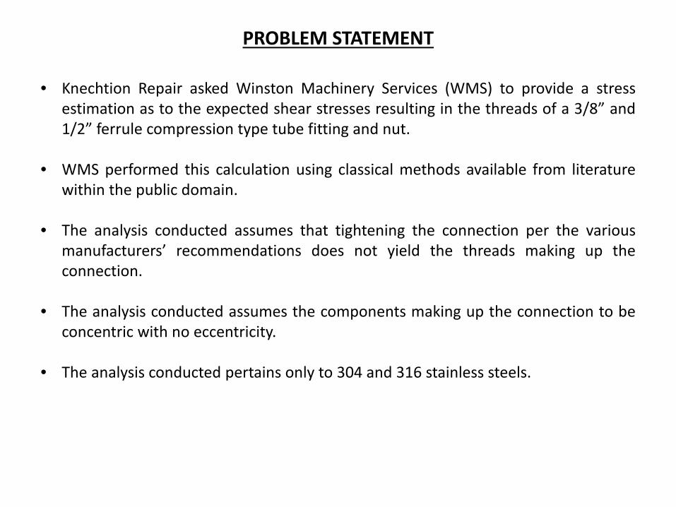
PROBLEM STATEMENT
• Knechtion Repair asked Winston Machinery Services (WMS) to provide a stress estimation as to the expected shear stresses resulting in the threads of a 3/8” and 1/2” ferrule compression type tube fitting and nut.
• WMS performed this calculation using classical methods available from literature within the public domain.
• The analysis conducted assumes that tightening the connection per the various manufacturers’ recommendations does not yield the threads making up the connection.
• The analysis conducted assumes the components making up the connection to be concentric with no eccentricity.
• The analysis conducted pertains only to 304 and 316 stainless steels.
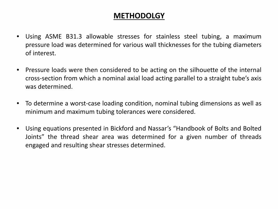
METHODOLGY
• Using ASME B31.3 allowable stresses for stainless steel tubing, a maximum pressure load was determined for various wall thicknesses for the tubing diameters of interest.
• Pressure loads were then considered to be acting on the silhouette of the internal cross-section from which a nominal axial load acting parallel to a straight tube’s axis was determined.
• To determine a worst-case loading condition, nominal tubing dimensions as well as minimum and maximum tubing tolerances were considered.
• Using equations presented in Bickford and Nassar’s “Handbook of Bolts and Bolted Joints” the thread shear area was determined for a given number of threads engaged and resulting shear stresses determined.
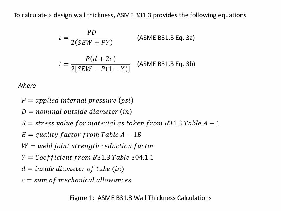
Figure 1: ASME B31.3 Wall Thickness Calculations
𝑡 =𝑃𝑃
2 𝑆𝑆𝑆 + 𝑃𝑃
𝑡 =𝑃 𝑑 + 2𝑐
2 𝑆𝑆𝑆 − 𝑃 1 − 𝑃
(ASME B31.3 Eq. 3a)
(ASME B31.3 Eq. 3b)
To calculate a design wall thickness, ASME B31.3 provides the following equations
Where
𝑃 = 𝑎𝑎𝑎𝑎𝑎𝑎𝑑 𝑎𝑖𝑡𝑎𝑖𝑖𝑎𝑎 𝑎𝑖𝑎𝑝𝑝𝑝𝑖𝑎 𝑎𝑝𝑎
𝑃 = 𝑖𝑛𝑛𝑎𝑖𝑎𝑎 𝑛𝑝𝑡𝑝𝑎𝑑𝑎 𝑑𝑎𝑎𝑛𝑎𝑡𝑎𝑖 𝑎𝑖
𝑆 = 𝑝𝑡𝑖𝑎𝑝𝑝 𝑣𝑎𝑎𝑝𝑎 𝑓𝑛𝑖 𝑛𝑎𝑡𝑎𝑖𝑎𝑎𝑎 𝑎𝑝 𝑡𝑎𝑡𝑎𝑖 𝑓𝑖𝑛𝑛 𝐵𝐵𝐵.𝐵 𝑇𝑎𝑇𝑎𝑎 𝐴 − 1
𝑆 = 𝑞𝑝𝑎𝑎𝑎𝑡𝑞 𝑓𝑎𝑐𝑡𝑛𝑖 𝑓𝑖𝑛𝑛 𝑇𝑎𝑇𝑎𝑎 𝐴 − 𝐵𝐵
𝑆 = 𝑤𝑎𝑎𝑑 𝑗𝑛𝑎𝑖𝑡 𝑝𝑡𝑖𝑎𝑖𝑠𝑡𝑠 𝑖𝑎𝑑𝑝𝑐𝑡𝑎𝑛𝑖 𝑓𝑎𝑐𝑡𝑛𝑖
𝑃 = 𝐶𝑛𝑎𝑓𝑓𝑎𝑐𝑎𝑎𝑖𝑡 𝑓𝑖𝑛𝑛 𝐵𝐵𝐵.𝐵 𝑇𝑎𝑇𝑎𝑎 𝐵04.1.1
𝑑 = 𝑎𝑖𝑝𝑎𝑑𝑎 𝑑𝑎𝑎𝑛𝑎𝑡𝑎𝑖 𝑛𝑓 𝑡𝑝𝑇𝑎 (𝑎𝑖)
𝑐 = 𝑝𝑝𝑛 𝑛𝑓 𝑛𝑎𝑐𝑠𝑎𝑖𝑎𝑐𝑎𝑎 𝑎𝑎𝑎𝑛𝑤𝑎𝑖𝑐𝑎𝑝
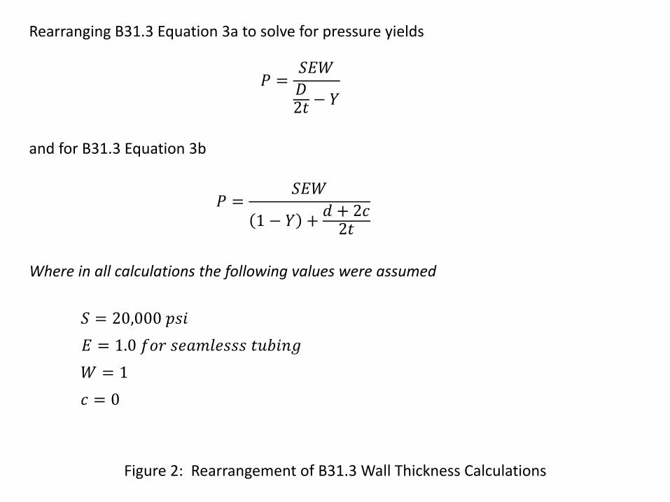
Figure 2: Rearrangement of B31.3 Wall Thickness Calculations
𝑃 =𝑆𝑆𝑆𝑃2𝑡 − 𝑃
𝑃 =𝑆𝑆𝑆
1 − 𝑃 + 𝑑 + 2𝑐2𝑡
Rearranging B31.3 Equation 3a to solve for pressure yields
and for B31.3 Equation 3b
Where in all calculations the following values were assumed
𝑆 = 20,000 𝑎𝑝𝑎
𝑆 = 1.0 𝑓𝑛𝑖 𝑝𝑎𝑎𝑛𝑎𝑎𝑝𝑝𝑝 𝑡𝑝𝑇𝑎𝑖𝑠
𝑆 = 1
𝑐 = 0
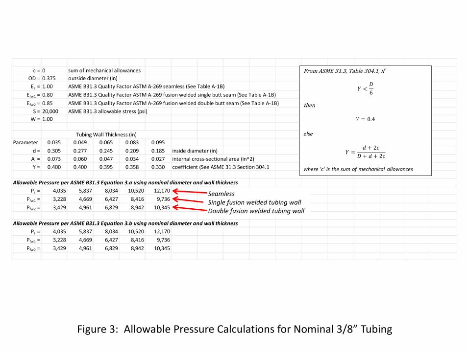
Figure 3: Allowable Pressure Calculations for Nominal 3/8” Tubing
c = 0 sum of mechanical allowancesOD = 0.375 outside diameter (in)Es = 1.00 ASME B31.3 Quality Factor ASTM A-269 seamless (See Table A-1B)
Efw1 = 0.80 ASME B31.3 Quality Factor ASTM A-269 fusion welded single butt seam (See Table A-1B)Efw2 = 0.85 ASME B31.3 Quality Factor ASTM A-269 fusion welded double butt seam (See Table A-1B)
S = 20,000 ASME B31.3 allowable stress (psi)W = 1.00
Tubing Wall Thickness (in)Parameter 0.035 0.049 0.065 0.083 0.095
d = 0.305 0.277 0.245 0.209 0.185 inside diameter (in)Ai = 0.073 0.060 0.047 0.034 0.027 internal cross-sectional area (in^2)Y = 0.400 0.400 0.395 0.358 0.330 coefficient (See ASME 31.3 Section 304.1
Allowable Pressure per ASME B31.3 Equation 3.a using nominal diameter and wall thicknessPs = 4,035 5,837 8,034 10,520 12,170
Pfw1 = 3,228 4,669 6,427 8,416 9,736Pfw2 = 3,429 4,961 6,829 8,942 10,345
Allowable Pressure per ASME B31.3 Equation 3.b using nominal diameter and wall thicknessPs = 4,035 5,837 8,034 10,520 12,170
Pfw1 = 3,228 4,669 6,427 8,416 9,736Pfw2 = 3,429 4,961 6,829 8,942 10,345
From ASME 𝐵𝐵.𝐵, Table 𝐵04.𝐵, if
𝑃 <𝑃6
then
𝑃 = 0.4
else
𝑃 =𝑑 + 2𝑐
𝑃 + 𝑑 + 2𝑐
where 'c' is the sum of mechanical allowances
Seamless Single fusion welded tubing wall Double fusion welded tubing wall
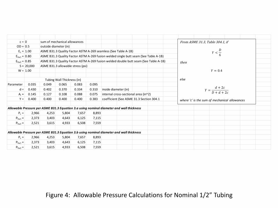
Figure 4: Allowable Pressure Calculations for Nominal 1/2” Tubing
c = 0 sum of mechanical allowancesOD = 0.5 outside diameter (in)Es = 1.00 ASME B31.3 Quality Factor ASTM A-269 seamless (See Table A-1B)
Efw1 = 0.80 ASME B31.3 Quality Factor ASTM A-269 fusion welded single butt seam (See Table A-1B)Efw2 = 0.85 ASME B31.3 Quality Factor ASTM A-269 fusion welded double butt seam (See Table A-1B)
S = 20,000 ASME B31.3 allowable stress (psi)W = 1.00
Tubing Wall Thickness (in)Parameter 0.035 0.049 0.065 0.083 0.095
d = 0.430 0.402 0.370 0.334 0.310 inside diameter (in)Ai = 0.145 0.127 0.108 0.088 0.075 internal cross-sectional area (in^2)Y = 0.400 0.400 0.400 0.400 0.383 coefficient (See ASME 31.3 Section 304.1
Allowable Pressure per ASME B31.3 Equation 3.a using nominal diameter and wall thicknessPs = 2,966 4,253 5,804 7,657 8,893
Pfw1 = 2,373 3,403 4,643 6,125 7,115Pfw2 = 2,521 3,615 4,933 6,508 7,559
Allowable Pressure per ASME B31.3 Equation 3.b using nominal diameter and wall thicknessPs = 2,966 4,253 5,804 7,657 8,893
Pfw1 = 2,373 3,403 4,643 6,125 7,115Pfw2 = 2,521 3,615 4,933 6,508 7,559
From ASME 𝐵𝐵.𝐵, Table 𝐵04.𝐵, if
𝑃 <𝑃6
then
𝑃 = 0.4
else
𝑃 =𝑑 + 2𝑐
𝑃 + 𝑑 + 2𝑐
where 'c' is the sum of mechanical allowances
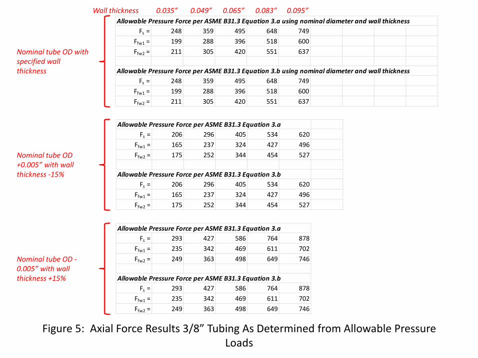
Figure 5: Axial Force Results 3/8” Tubing As Determined from Allowable Pressure Loads
Allowable Pressure Force per ASME B31.3 Equation 3.a using nominal diameter and wall thicknessFs = 248 359 495 648 749
Ffw1 = 199 288 396 518 600Ffw2 = 211 305 420 551 637
Allowable Pressure Force per ASME B31.3 Equation 3.b using nominal diameter and wall thicknessFs = 248 359 495 648 749
Ffw1 = 199 288 396 518 600Ffw2 = 211 305 420 551 637
Allowable Pressure Force per ASME B31.3 Equation 3.aFs = 206 296 405 534 620
Ffw1 = 165 237 324 427 496Ffw2 = 175 252 344 454 527
Allowable Pressure Force per ASME B31.3 Equation 3.b Fs = 206 296 405 534 620
Ffw1 = 165 237 324 427 496Ffw2 = 175 252 344 454 527
Allowable Pressure Force per ASME B31.3 Equation 3.aFs = 293 427 586 764 878
Ffw1 = 235 342 469 611 702Ffw2 = 249 363 498 649 746
Allowable Pressure Force per ASME B31.3 Equation 3.b Fs = 293 427 586 764 878
Ffw1 = 235 342 469 611 702Ffw2 = 249 363 498 649 746
Nominal tube OD with specified wall thickness
Nominal tube OD +0.005” with wall thickness -15%
Nominal tube OD -0.005” with wall thickness +15%
0.035” 0.049” 0.065” 0.083” 0.095” Wall thickness
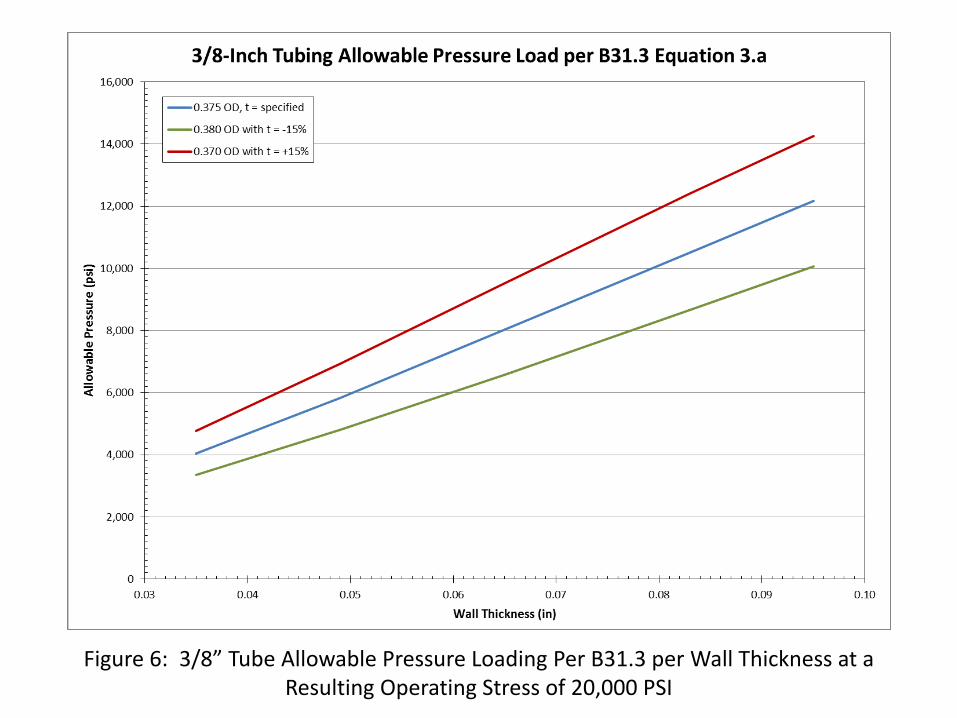
Figure 6: 3/8” Tube Allowable Pressure Loading Per B31.3 per Wall Thickness at a Resulting Operating Stress of 20,000 PSI
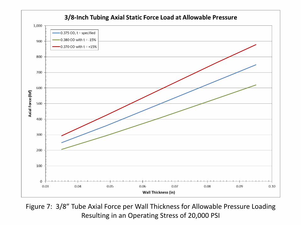
Figure 7: 3/8” Tube Axial Force per Wall Thickness for Allowable Pressure Loading Resulting in an Operating Stress of 20,000 PSI
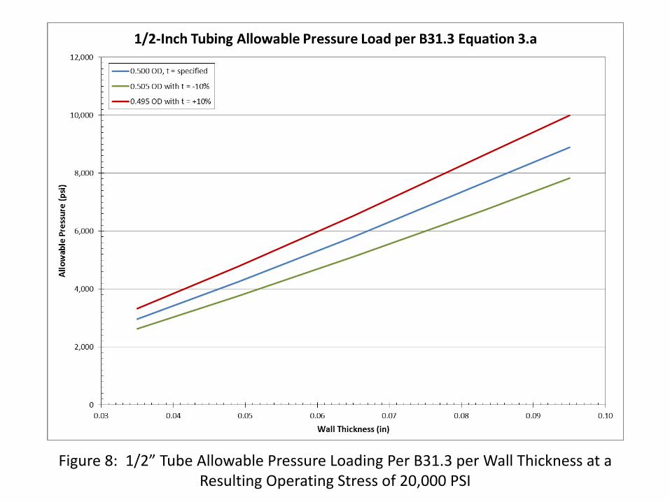
Figure 8: 1/2” Tube Allowable Pressure Loading Per B31.3 per Wall Thickness at a Resulting Operating Stress of 20,000 PSI
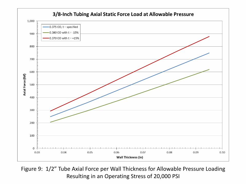
Figure 9: 1/2” Tube Axial Force per Wall Thickness for Allowable Pressure Loading Resulting in an Operating Stress of 20,000 PSI

Figure 10: Thread Shear Stress Calculation for 3/8” Tube Operating at Allowable Wall Stress of 20,000 PSI
9/16-20UND = 0.375 nominal thread diameter (in)
D1max = 0.5162 maximum minor diameter of internal thread (in)D2max = 0.5341 maximum pitch diameter of internal thread (in)d1min = 0.5544 minimum major diameter of external thread (in)d2min = 0.5268 minimum pitch diameter of external thread (in)
TPI = 20 threads per inchp = 0.05 thread pitch (in)
External Thread Shear AreaNumber of Threads Engaged
Parameter 2 3 4 5 6 7LE = 0.100 0.150 0.200 0.250 0.300 0.350 Length of thread engagement (in)
Ashr.ext = 0.101 0.151 0.202 0.252 0.303 0.353 External thread shear area (in)
τs_ 0.035 = 2,461 1,641 1,231 985 820 703 Resulting shear stress on fitting for 0.035 inch tube wall thickness (psi)τs_ 0.049 = 3,561 2,374 1,780 1,424 1,187 1,017 Resulting shear stress on fitting for 0.049 inch tube wall thickness (psi)τs_ 0.065 = 4,901 3,267 2,451 1,960 1,634 1,400 Resulting shear stress on fitting for 0.065 inch tube wall thickness (psi)τs_ 0.083 = 6,418 4,278 3,209 2,567 2,139 1,834 Resulting shear stress on fitting for 0.083 inch tube wall thickness (psi)τs_ 0.095 = 7,425 4,950 3,712 2,970 2,475 2,121 Resulting shear stress on fitting for 0.095 inch tube wall thickness (psi)
Internal Thread Shear AreaNumber of Threads Engaged
Parameter 2 3 4 5 6 7LE = 0.100 0.150 0.200 0.250 0.300 0.350 Length of thread engagement (in)
Ashr.ext = 0.128 0.192 0.256 0.320 0.384 0.448 External thread shear area (in)
τs_ 0.035 = 1,942 1,295 971 777 647 555 Resulting shear stress on fitting for 0.035 inch tube wall thickness (psi)τs_ 0.049 = 2,810 1,873 1,405 1,124 937 803 Resulting shear stress on fitting for 0.049 inch tube wall thickness (psi)τs_ 0.065 = 3,867 2,578 1,934 1,547 1,289 1,105 Resulting shear stress on fitting for 0.065 inch tube wall thickness (psi)τs_ 0.083 = 5,064 3,376 2,532 2,026 1,688 1,447 Resulting shear stress on fitting for 0.083 inch tube wall thickness (psi)τs_ 0.095 = 5,859 3,906 2,929 2,343 1,953 1,674 Resulting shear stress on fitting for 0.095 inch tube wall thickness (psi)
𝐴𝑆𝑒𝑥𝑡 =𝜋 ∙ 𝐿𝑆 ∙ 𝑃1𝑚𝑎𝑥
𝑎𝑎2 + 0.577𝐵5 𝑑2𝑚𝑖𝑛 − 𝑃1𝑚𝑎𝑥
Source: Bickford and Nassar
𝐴𝑆𝑖𝑛𝑡 =𝜋 ∙ 𝐿𝑆 ∙ 𝑑1𝑚𝑖𝑛
𝑎𝑎2 + 0.577𝐵5 𝑑1𝑚𝑖𝑛 − 𝑃2𝑚𝑎𝑥
Source: Bickford and Nassar
Worst case thread shear stress results on the external thread
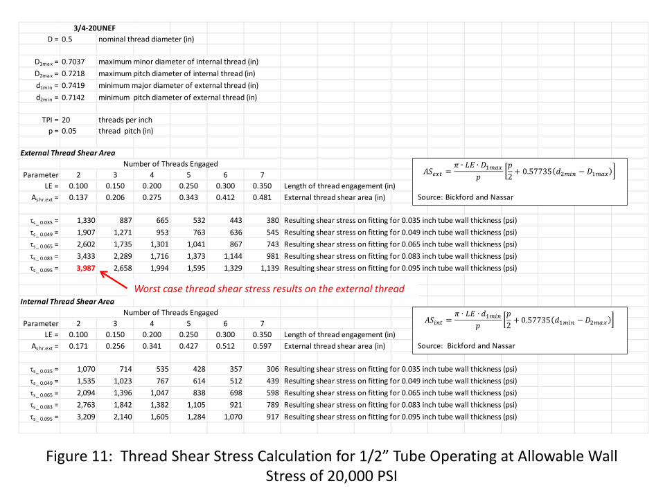
Figure 11: Thread Shear Stress Calculation for 1/2” Tube Operating at Allowable Wall Stress of 20,000 PSI
3/4-20UNEFD = 0.5 nominal thread diameter (in)
D1max = 0.7037 maximum minor diameter of internal thread (in)D2max = 0.7218 maximum pitch diameter of internal thread (in)d1min = 0.7419 minimum major diameter of external thread (in)d2min = 0.7142 minimum pitch diameter of external thread (in)
TPI = 20 threads per inchp = 0.05 thread pitch (in)
External Thread Shear AreaNumber of Threads Engaged
Parameter 2 3 4 5 6 7LE = 0.100 0.150 0.200 0.250 0.300 0.350 Length of thread engagement (in)
Ashr.ext = 0.137 0.206 0.275 0.343 0.412 0.481 External thread shear area (in)
τs_ 0.035 = 1,330 887 665 532 443 380 Resulting shear stress on fitting for 0.035 inch tube wall thickness (psi)τs_ 0.049 = 1,907 1,271 953 763 636 545 Resulting shear stress on fitting for 0.049 inch tube wall thickness (psi)τs_ 0.065 = 2,602 1,735 1,301 1,041 867 743 Resulting shear stress on fitting for 0.065 inch tube wall thickness (psi)τs_ 0.083 = 3,433 2,289 1,716 1,373 1,144 981 Resulting shear stress on fitting for 0.083 inch tube wall thickness (psi)τs_ 0.095 = 3,987 2,658 1,994 1,595 1,329 1,139 Resulting shear stress on fitting for 0.095 inch tube wall thickness (psi)
Internal Thread Shear AreaNumber of Threads Engaged
Parameter 2 3 4 5 6 7LE = 0.100 0.150 0.200 0.250 0.300 0.350 Length of thread engagement (in)
Ashr.ext = 0.171 0.256 0.341 0.427 0.512 0.597 External thread shear area (in)
τs_ 0.035 = 1,070 714 535 428 357 306 Resulting shear stress on fitting for 0.035 inch tube wall thickness (psi)τs_ 0.049 = 1,535 1,023 767 614 512 439 Resulting shear stress on fitting for 0.049 inch tube wall thickness (psi)τs_ 0.065 = 2,094 1,396 1,047 838 698 598 Resulting shear stress on fitting for 0.065 inch tube wall thickness (psi)τs_ 0.083 = 2,763 1,842 1,382 1,105 921 789 Resulting shear stress on fitting for 0.083 inch tube wall thickness (psi)τs_ 0.095 = 3,209 2,140 1,605 1,284 1,070 917 Resulting shear stress on fitting for 0.095 inch tube wall thickness (psi)
𝐴𝑆𝑒𝑥𝑡 =𝜋 ∙ 𝐿𝑆 ∙ 𝑃1𝑚𝑎𝑥
𝑎𝑎2 + 0.577𝐵5 𝑑2𝑚𝑖𝑛 − 𝑃1𝑚𝑎𝑥
Source: Bickford and Nassar
𝐴𝑆𝑖𝑛𝑡 =𝜋 ∙ 𝐿𝑆 ∙ 𝑑1𝑚𝑖𝑛
𝑎𝑎2 + 0.577𝐵5 𝑑1𝑚𝑖𝑛 − 𝑃2𝑚𝑎𝑥
Source: Bickford and Nassar
Worst case thread shear stress results on the external thread
CONCLUSIONS
• Results show that for the conditions considered and the assumptions made, the estimated thread shear stresses for the thread types considered are significantly less than the yield strength of either 304 or 316 stainless steel which is generally taken at room temperature to be 35 ksi and 37 ksi respectively.
• The analysis made considers the forces developed with the tubing wall operating at an allowable operating stress of 20 ksi per ASME B31.3
• Considering that many plant systems, such as instrument air, operate at pressures
significantly less than those necessary to create the maximum allowable stress in the tubing wall, a corresponding decrease in thread stress and a higher factor of safety obtained in compression fitting type connection.
• The analysis effort undertaken is only a stress estimation based on the
methodology employed. Where pressures approaching those necessary to produce the maximum allowable tubing wall stress of 20 ksi are present, it is prudent that due diligence be applied - especially where critical systems and personnel safety concerns are present.
DISCLAIMER
The thread stress estimation conducted is relevant only to the conditions considered and the assumptions made. It does not consider the many combinations of temperature, operating pressure, mechanical loading, support, restraint, environmental, maintenance, and/or assembly influences to which a compression fitting type connection considered is subject to. Thus, Winston Machinery Service makes no warranty declaration, either explicit or implied, related to the work presented and its use, nor does Winston Machinery Service accept responsibility for damages or injury resulting from the use of the work presented.