Embed Size (px)
Citation preview
MECHANIZATION AND AUTOMATION OF MINING
ESTIMATE OFT HE INFLUENCE OF IMPACT SYSTEM PARAMETERS AND THE MEDIUM
BEING TREATED ON THE RATE OF IMPACTOR MOTION AFTER IMPACT
O. D. Alimov, V. K. Manzhosov, and V. E. Erem'yants
One of the factors exerting influence on their operating mode in many impact mechan/sms is the rate of impactor motion after is collislonwith a tool [1-3]. This rate is given by using the rate restoration factor R, equal to the ratio of the impactor velocities after and prior to impact, when designing machines of impacting action. The value of the restoration factor is ordinarily taken to be 0.3-0.5 for impact systems with the most diverse para- meters and when using these systems to treat different media.
Theoretical and experimental investigations [i, 3, 4] show that the rate of Impactor recoil from an instrument depends on the parameters of the impact system elements and the resistance characteristics of the medium to the insertion of the tool. Neglecting these dependences can result in the impact mechanism devlatlng from the given mode or operating in the domain of an unstable mode during exploitation. Consequently, in designing machines of impact action it is quite important to know the nature of the change in Impactor motion velocity after impact as a function of the 4-T. act system parameters and the properties of themedlumbeing treated.
Such dependences were obtained and analyzed in [4] for an impact system in which the Impactor and instrument impact stiffnesses were identical. The impact stiffness C is under- stood to be the product of the acoustic stiffness of the element under consideratio~s pu (where p is the density of the element material and u is the strain wave propagation velocity therein) and its cross-sectlonal area F, i.e., C - puF.
In many impact system constructions the impactor 4--jact stiffness is greater than that for the tool. No analytic expressions permittSng est/mation of the influence of the system par-meters and the properties of the medium being treated on the rate of impact motion after impact exist for such systm,- at this time. In this connection, the problem of this paper is to obtain and analyze such expressions.
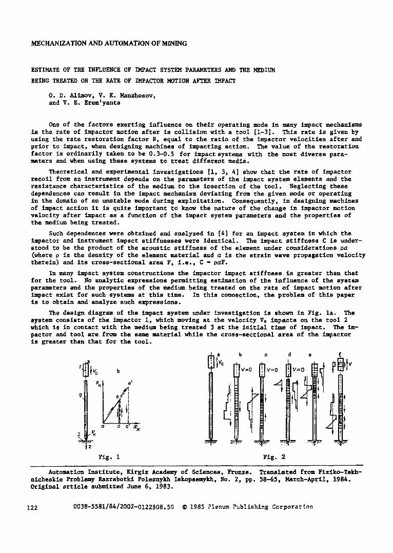
The design diagrsm of the impact system under investigation is shown in Fig. la. The system consists of the Impactor i, which moving at the velocity Ve impacts on the tool 2 which is in contact with the medi~ being treated 3 at the initial time of impact. The Im- pactor and tool are from the same material while the cross-sectional area of the Impactor is greater than that for the tool.
'I ~0 b
I ./,I 2 I e~ I
I _ a ,~ C a ~
3 ~
Iz
a b
,v0 !
C
V=O
!
Ze ~7
Fig. I Fig. 2
d �9
Automation Institute, K/rgiz Academy of Sciences, Frunze. Translated from Fiziko-Tekh- nicheskie Problemy Razrabotk/ Poleznykh Zskopaemykh, No. 2, pp. 58-65, March-April, 1984. Original article submltted 3une 6, 1983.
122 0038-5581/84/2002-0122508.50 �9 1985 Plenum ?ub!ishing Corporaclon
St is assumed that the characteristic resistance of the medium to insertion of the tool therein has the form represented in Fig. lb. In conformity with this characteristic, the resistance Pk of the medium being treated increases with insertion of the tool in propor- tion to the magnitude of the insertion x k (the section ab in Fig. ib). If the forces acting on the medium are insufficient to overcome its resistance, then the contact section of the tool and the medium is fixed (the section bc). As the forces acting on the medium grow above the magnitude of its resistance, the subsequent insertion of the tool occurs in conformity with section 55' of the Pk(Xk) diagram (Fig. ib). Such a dependence of the resistance of the medium on the magnitude of tool insertion is characteristic for the insertion of an tool with wedge rock-rupturlng blades into a firm rock mass [5].
It is also assumed that the longitudinal dimensions of the system elements are several t~m~s greater than the transverse dimensions while the energy losses by internal friction in the element material and the scattering in the surrounding medium are negliblbly small. Un- der these assumptions, the motion of the impactor and tool sections is described by a one, d4meusional wave equation
~z -- a' ~" (1) o~ t t #z "- '~ '
where �9 i s t h e d i sp l acemen t o f the s e c t i o n , z i t s c o o r d i n a t e , and t i s t ime.
Zn c o n f o r m i t y with the D'Alembert method, the solution of the wave equation is represen- ted in the form
zCz, t) - lCa t - z) + ~Cat + z), (2)
where f(z, t), ~ (z, t ) are functions describing the displacement of the sections in strain waves being propagated over elements of the impact system in and opposite to the direction of the medium being treated, respectively.
The forms of the functions f(z, t) and ~(z, t) are found from the boundary condition, which are written thus for the impacting endfaces of the i~pactor and tool in the presence of c o n t a c t
zAO, t)=z,(O, t); V,(O, t)•. V,(O, t),
and in the absence of c o n t a c t
(3)
o~ l (0, t) az, (0, 0 o----7-- -- ~, = 0, (4)
where xx, x2 are, respectively, the displacement of the impacting endfaces of the Impactor and the tool, and Vx, Va are their velocities.
The boundary conditions on the tool endface interacting with the medium being treated had the form
O= s (Z, 0 E,F, o~+kzf f i ( l , t ) ffi-O, at" F,(l,t)>0, (5)
z.(l, t ) f x ~ , ~ at V,(I, t ) - -O, (6) ax s (l, t)
a--------~-- =" 0 at F , ( I , t ) < O , ( 7 )
where E2, F~ are, respectively, the elastic modulus of the material and the cross-sectlonal area of the tool, k is the stiffness of tool contact ~rlth the medium being treated which is determined from the Pk(Xk) diagram (Fig. Ib) as k = Pk/X k.
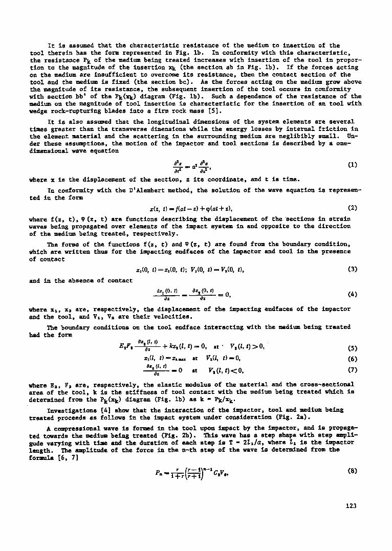
Investigations [4] show that the interaction of the impactor, tool and medium being treated proceeds as follows in the impact system tmd_er consideration (Fig. 2a).
A compressional wave is formed in the tool upon impact by the impactor, and is propaga- ted towards the medium being treated (Fig. 2b). This wave has a step shape with step ampll- gude varying with time and the duration of each step is T - 2~x/a, where 7.x is the impactor length. The --Tlltude of the force in the n-th step of the wave is determined from the fo rmula [6, 71
p, v [r-- i\"-1~ ,. cs>
123
where r = Cz/C2 is the ratio between the Impactor and tool impact stJffnesses and Vo is Im- pactor velocity prior to ~-Tact.
Theoretically, the duration of the wave being formed in the tool by an impactor with large impact stiffness is infinite. However, it can be shown that for 1 < r < i0 not less than 97Z of the initial impactor energy is contained in the first r steps of this wave, while not less than 99.9Z is contained in 2r steps. In the latter case, more than 98Z of the momentum that the impactor had prior to impact is transmitted to the tool after the for- marion of 2r step waves. Therefore, it can be assumed that the process of wave formation in the tool has termlnated after a time T - 2rT and the impactor has stopped and is in contact with the tool.
Those systems in which the strain wave reflected from the medlumbeing treated is re- turned to the impact endface of the tool after termlnatlon of the process of initial wave formation are eT-m~ned in this paper. As follows from the above-mentloned data, this condi- tion is satisfied sufficiently well for a tool length 2r times greater than the impact length.
The compressional wave being propagated toward the medium being treated reaches the lower endface of the tool and by displacing it assures insertion into the medium. Since, the resistance to insertion is slight at the initial time, then the compression wave acting on the lower endface of the instrument is reflected as a tension wave. The resistance of the medium increases as the force is inserted. Consequently, the tension wave ~-Tlitude diminishes and at a certain time a compression wave is reflected from the medium.
Therefore, after insertion of the tool into the medium, a strain wave consisting of a tension section (Fig. 2c) followed by a compression section is propagated towards the impact endface in the medium. The tension wave is here reflected from the free impact endface of the tool towards the medium being treated with an opposite sign of the strain, i.e., by a compression wave (Fig. 2d). Since the impactor transmitted all its energy to the tool dur- ing formation of the initial wave, then it r~m-ins fixed after the tool leaves it.
The compressions/ wave follows the tension wave to the impact endface of the tool and displaces it in the direction of the impactor. For definite impacting system parameters and contact stiffness of the tool with the medium a duplicate contact between the tool and the impactor can be formed. In this case, the compression wave being propagated over the tool, passes partially into the Impactor (Fig. 2e) and is partially reflected towards the medium being treated. The parameters of the transmitted and reflected waves depend on the ratio between the impact stiffnesses of the impactor and the tool.
On being propagated over the impactor, the compressional wave displaces its upper free endface causing the origination of an unloading wave therein that moves downward over the impactor. The forces in this wave equal zero, and the displacements of the sections are directed oppositely to the tool. The unloading wave, on reaching the impacting endface of the impactor, can result in its stand-off from the instrumentunder definite parameters for the impacting system (Fig. 2f). The times at which the formation of a duplicate contact of the impact system elements occurs under the action of a reflected wave and the impactor stand-off from the instrument, depend on the system parameters and the stiffness of a tool c o n t a c t w i t h t h e medium.
After the impactor stands off from the tool, its sections, by perfo~m/ng periodic mo- tion, are displaced oppositely to the tool. The mean velocity of section motion, equal to the ratio of their displacement within one period of oscillat~on and the duration of this period, can be found by considering the change in impactor momentum u~der the action of force pulses occurring in its contact section with the tool.
In conformity with the representations elucldated for the interaction process of impac- tot, tool, and medium being treated, finding the analytic expressions to determine the rate of impactor motion after impact was performed as follows.
First the displacements of the sections in the strain wave formed by the ~-Tactor in the tool were determlned. Then by using the boundary conditions (5)-(7), the process of inter- action of this wave wlth the medium being treated was considered and displacements of the sections were found in the wave reflected from the medium upon insertion of the tool. Later by using the boundary conditions (3)-(4) the dlsplac~t of the impacting endface of the tool was determined under the action of a reflected wave and the moment of formation of its
124
t"
4
3
,i
r ! , r
i~ . ~ /
o,4 o,8 r ~,s o
F i g . 3
Y
-.~,s k~'~z
-o,z ~
o o,~ o,8 42 46 s
F i g . 4 ) r ffi 1 ; 2 ) r = 2 ; 3 ) r ffi 3 ; 4 ) r - 4 .
duplicate contact wlth the impactor. Afterwards, the process of compression wave transmis- sion in the impactor was determined, and the forces acting in the Impactor contact with the tool~ the time of termination of the duplicate interaction of these elements, and the im- pulse of the forces acting on the impactor were all found. Then by equating the change in impactor momentum to the sum of the impulses of the forces acting on its impacting endface during interaction with the tool, the mean rate of motion of the impactor center of mass was determined after its recoil from the tool.
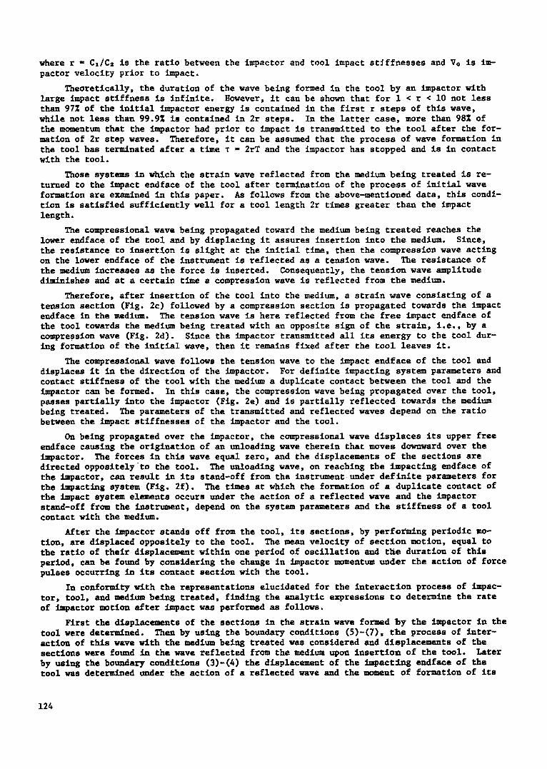
Investigations performed according to the algorithm developed here showed that the rate of ~mpactor motion after impact is directly proportional to its initial velocity and depends on the ratio between the impactor and tool impact stiffnesses r and the dimensionless para- meter 8. The parameter 8 is the ratio of the square of the instrument impact stiffness to the product of the stiffness of tool contact with the medium by the impactor mass 8 = Ca=/ kmx.
The formulas to determine the rate of impactor motion are different in distinct ranges of variation of the parameters 6 and r. This is related to the fact that insertion of the tool into the medium, formation of its duplicate contact with the impactor, and cessation of this contact occurs under the action of different steps of the initial strain wave and that reflected from the medium.
Domains of variation of the parameters 8 and r in which the rate of impactor motion is determlned by different formulas are shown in Fig. 3. Insertion of the tool into the medium occurs in doms/ns I - VI only under the action of the first step wave formed by the impactor in the instrument, in domains VII - IX under the acticm of two steps, and in the domain X under the action of three steps in the initial wave.
The duplicate contact of the tool with the impactor in domains I - IV is formed under the action of the first step wave reflected from the medium be4~s treated, while under the action of subsequent steps in domains V - VIII. Impactor contact with the instz~-,~nt under the action of the first wave reflected from the medium does not occur in domain X.
The staDd-off of the impactor from the tool after their duplicate interaction in domains I, V, VII occurs after a t~e T while in domains IV, VI, VIII it occurs after a time 2T from the time of formation of the duplicate contact between these bodies.
Presented below are the formulas to determine the relative 4,Tactor velocity after im- pact that are obtained as a result of the investigations executed. In thlse formulas R i - Vi/Ve, where the subscript i dlsplays the number of the domain of variation of the parameters 8 and r (FIE. 3), to which the formula corresponds:
n x = - - Q ' r ( t - - S + 0 , 8 0 r q ) ,
Rax - - - - Q*r [t - - 0 . 5 B + 0 . 8 e r q - - 0 . 5 (Q - q) 8 r I n ~__4r,
Rxxx -- - - QIrq (2 - - B ) ,
R x v - - - - QSrq [2 - - S - - 0 ,8%r (Q - q)], ( 9 )
R v x ~- - 2Q*rq ( t - - QB),
Rvxx " - - - Q*r [ t - - Q 8 (q + e x p ( - 218r))] ,
R v x u - - 2Q*rq [ i - QB (q + e x p ( - - 2 /8 r ) ) ]
125
v_ ro
~,~
o,4 o,a t,2 ~,8 e.
-0,8
F i g . 5
o,4 M t,2 t,~ e
w h e r e
2 r--i Q =ffi T-~7; q - - ~ ; B -= %r (t -~ exp ( - - 2/er)).
The formulas to determine the impactor velocity In the domain of variation of the para- meters e and r that is shaded in Fig. 3 will not be presented since the domain Is relatively small and Its appropriate formula is quite awkward.
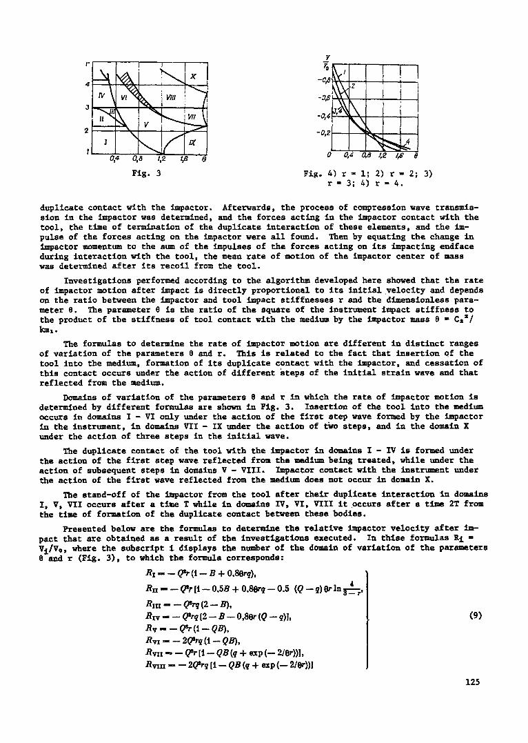
Diagrams of the change in the relatlve velocity of the impactor after impact are repre- sented in Fig. 4 as a function of the parameters % and r constructed by means of (9) with the domains of their applicability, displayed in Fig. 3, taken Into account. It is seen from Fig. 4 that for values of the parameter e less than 0.7 and increase from 1 to 3 in the ratio between the impactor and tool impact stlffnesses will result in a diminution in the veloclty of Impactor motion after impact, and an increase In this velocity for % > 1.0. As the para- meter r increases further:'above 3, it exerts practically no influence on the velocity of im- pactor motion.
The system under consideration is most responsive to a change in the rat4o between the impact stlffnesses of its elements for 8 - 0.3-0.5. In this range of variation of the par-~meter 8 an increase in the ratio r from 1 to 2 results In a diminution In the impactor velocity of recoil from the tool of 1.4-1.5 times, while a further increase in r to 3 will result in a reduction in the 4,npactor velocity by an additional 7-14Z.
The Sraphs represented in Fig. 4 are valid for the case when only the first wave reflec- ted from the medium being treated acts on the impactor. By returning to the lower endface of the instrument (Fig. 2f) this wave is again reflected towards the impact andface. By displacing the ~mpact endface, the second wave reflected from the medium can result in the formation of a subsequent impactor contact with the instrument. A force impulse which will result in an increase in velocity as compared with the values represented in Fig. 4, will here act on the impactor.
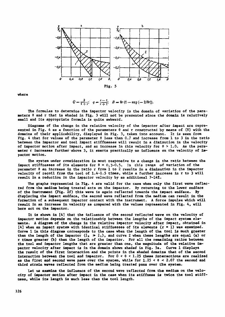
It is shown in [4] that the influence of the second reflected wave on the velocity of impactor motion depends on the relationship between the lengths of the ~npact system ele- ments. A diagr am of the change in the relative impactor velocity after impact, obtained in [4] when an impact system with identical stlffnesses of its elements (r - I) was ~=-m4ned. Curve i in this diagram corresponds to the case when the length of the tool is much greater than the length of the impactor (~2 ~ ~l), and curve 2 when these lenschs are equal (a) or r times greater Co) than the length of the impactor. For all the remaining ratios between the tool and impactor lengths that are greater than one, the magnitude of the relative im- pactor velocity after impact is in the domain shown shaded in Fig. 5a. Curve 1 displays the result of the first interaction and the points in the shaded domains that of the second interaction between the tool and impactor. For 0 �9 8 < 1.25 these interactions are realized as the first and second wave pass over the system, while for 1.25 �9 8 �9 2.07 the second and Chlrd strain waves reflected from the medium being treated pass over the system.
Let us examine the 4-fluence of the second wave reflected from the medium on the velo- e/cy of Impactor motion after i~pact in the case when Its stiffness Is twice the tool stiff- hess, while its length is much less than the tool length.
126
It is seen from Flg. 4 that for r - 2 and 0 - 1.7 the impactor velocity after passage of the first wave reflected from the medium over the system is zero. Thls is explained by the fact that for such system parameters Impactor contact wlth the tool is formed at the final time of action of the first reflected wave on the impacting endface of the instrument, when the whole wave was already reflected from the endface towards the medium being treated. In this case it is fixed and in contact with the Impactor prior to the arrival of the second reflected wave at the impacting endface. Passing to the Impactor, the second wave results in Its recoil-from the tool at a certain velocity. Consequently a Jump in the function E appears on the R(O) diagram.
Computations of the process of second wave energy transmission to the impactor show that for r = 2, 0 = 1.7 the relative velocity of impactor recoll from the tool Is 0.315 (Fig. 5b). As the parameter 8 increases further, thls velocity diminishes, which is associated with the presence of a gap between the instrument and the impactor at the time the second reflected wave approaches the impact endface of the instrument. The higher the value the parameter 8 has, the greater the magnitude of the gap, and the greater the portion of the second wave reflected from the free endface of the tool towards the medium being treated before the for- matlon of Its duplicate contact with the impactor.
It is seen from a comparison of the dlaEr-m- in Figs. 5a end b that as the ratio between the impactor and tool impact stlffnesses increases, the Jump in the function R(8) while the amplltude of thls Jump diminishes.
By analogy with the solutlon obtained in [4], It can be assumed that the upper boundary of the values of R corresponding to the action of subsequent waves in the impactor is des- cribed by the curve 2 displayed in Flg. 5b, while the magnitudes of the impactor recoil velo- city from the instrument will lle in the shaded domain In Fig. 55 for different relationships between the lengths of these elements that are greater than r.
It is seen from Flg. 5 that in different ranges of variation of the parameter O an in- crease in the ratio of the impact stlffnesses of the system elp~ents influences the impactor recoil velocity from the tool in a different manner. For instance, for 0 < % < 1.0 the in- crease in r results in a velocity reduction while for 1.0 < 8 both its increase and decrease are possible depending on the ratio between the impactor and the instrument lengths. For different values of this ratio that satisfy the assumption that the stracLn waves reflected from the medium exert no influence on the process of initial wave formation in the instru- ment, the impactor recoil velocity changes from 0 to 0.4 Ve for 1.0 < 8 < 2.0 and 1 < r < 4.
As already noted, the parameter 8 is the ration between the square of the tool impact stiffness and the product of the tool contact stiffness with the medium by the mass of the impactor (0 = C2a/km). During machine operation the stiffness contact of the tool with the medium from impact to impact changes because of the Inhomogenelty in the properties of the medium being treated, end of wear in the tool. Consequently, in real syst~,~- it Is impossi- ble to assure a constant value of the parameter 8 and when designing machines it is necessary to be oriented toward a certain range of its variation.
It is shown In [6] that in order to assure the best transmission of impact energy to the medium being treated with the linear characteristic of its resistance to the insertion of a tool, It is expedient to select the impact system parameters in such a manner that the quan- tity 0 would be in the 1.0-2.0 range. For such system par-~-~ters the most probably value of the impactor recoil velocity from the tool will lle between the llm4ts 0-0.3 Vo. This domain of variation of impactor recoil velocity from the instrument should indeed be taken in the analysis and design of machines of impact action that are used for drilling boreholes and wells In flrm mounted rocks.
The fundamental results of the investigations performed can be formulated as follows.
Analytical expressions have been obtained to determine the velocity of impactor motion after impact on a tool interacting with the medium being treated with a linear characteris- tic for its resistance to insertion of a tool. Analysis of these expressions showed that the ~mpactor recoil velocity from the tool depends on the relationship between the cross- sectional areas of these el~-~ts, their lengths, and the d~nsionless par-meter 8 that Is the ratio between the characteristics of the impact system elements and the medium being
treated.
127
For values of the parameter O less than one an increase in the ratio between the impact and tool cross-sectional areas from 1 to 3 will result in d~m~nution in the impactor recoil velocity from the tool. As this ratio increases further, the impactor recoil velocity varies insignificantly.
In impact syst~,,- with rational parameters that assure a change in the value of O from 1 to 2 during machine operation, the most probable values of the impactor recoil velocity from the tool for different relationships between the lengths of the impact system elements and their cross-sectlonal areas that satisfy the condition that the strain waves reflected from the medium being treated do not exert influence on the process of initial wave formation in the tool will lle in the range 0-0.3 V@ (where Vo is the impactor velocity prior to ~apact).
The r e s u l t s obtained can be used in the - e ~ l y s i s and design of impact ac t ion machines.
LITERATURE CITED
I. V. u Gorbunov, V. I. Baburov, and L. S. Redutlnskii, "Experimental studies of the in- fluence of the elastic properties of materials being treated on the internal processes and parameters of a manual pneumatic b--,,er," Izv. Vyssh. Uchebn. Zaved., Gornyl Zh., No. 1 (1965).
2. V. K. M-n~hosov and N. O. Lukutina, Dye-talcs of Electromagnetic Generators of Powerful Impulses [in Russian], 111m, Frunze (1979).
3. N. I. Niklshin, "Recoil of a driver and its influence on operation of pne,-,-tlc drills and concrete breakers," Trudy VNIIStroldormash., Vol. 30. Investigation and Analysis of Impact Mechanisms [in Russian], Moscow (1961).
4. V. K. Manzhosov, V. E. Erem'yants, and Yu. V. Nevenchannyl, "Investigation of driver motion during impact on an instrument interaction with the medium being treated," Trudy Niklaevskogo Korablestroltel'nogo Instltuta, No. 169. Dy~-m~cs and Strength of Ship Machines [in Russian], Nikolaev (1980).
5. A. F. Lisovskil and L. T. Dvornlkov, "On the question of the resistance of mountain rock to the dy-am~c insertion of an instrument," Perfection of Drilling Machines [in Russian], Ilia, Fr-n~e (1970).
6. O. D. Allmov, V. K. Manzhosov, and V. E. Erem'yants, Strain Wave Propagation in Impact Systems [in Russian], llim, Frunze (1978).
7. K. I. Ivanov, M. S. Varlch, V. I. Dusev, and V. D. Andreev, Drilling Technique in the Development of Useful Ore Deposits [in Russian], Nedra, Moscow (1974).
128