Embed Size (px)
Citation preview

ESTCPCost and Performance Report
ENVIRONMENTAL SECURITYTECHNOLOGY CERTIFICATION PROGRAM
U.S. Department of Defense
(PP-9608)
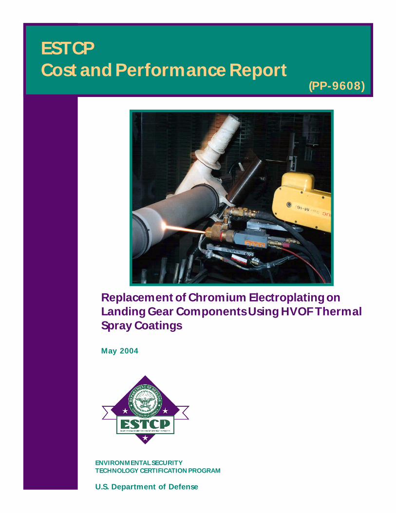
Replacement of Chromium Electroplating onLanding Gear Components Using HVOF ThermalSpray Coatings
May 2004

i
COST & PERFORMANCE REPORT ESTCP Project: PP-9608
TABLE OF CONTENTS
Page
1.0 EXECUTIVE SUMMARY .................................................................................................1
1.1 BACKGROUND .....................................................................................................1 1.2 OBJECTIVES OF THE DEMONSTRATION........................................................1 1.3 REGULATORY DRIVERS ....................................................................................2 1.4 DEMONSTRATION RESULTS.............................................................................2 1.5 STAKEHOLDER/END-USER ISSUES .................................................................3
2.0 TECHNOLOGY DESCRIPTION .......................................................................................5
2.1 TECHNOLOGY DEVELOPMENT AND APPLICATION...................................5 2.2 PROCESS DESCRIPTION .....................................................................................6 2.3 PREVIOUS TESTING OF THE TECHNOLOGY .................................................9 2.4 ADVANTAGES AND LIMITATIONS OF THE TECHNOLOGY.......................9
3.0 DEMONSTRATION DESIGN .........................................................................................11
3.1 PERFORMANCE OBJECTIVES .........................................................................11 3.2 SELECTION OF TEST FACILITY......................................................................12 3.3 TEST FACILITY HISTORY AND CHARACTERISTICS .................................12 3.4 PHYSICAL SETUP AND OPERATION .............................................................13 3.5 SAMPLING AND MONITORING PROCEDURES............................................14 3.6 ANALYTICAL METHODS .................................................................................16
3.6.1 Fatigue.................................................................................................... 16 3.6.2 Corrosion................................................................................................ 17 3.6.3 Wear....................................................................................................... 18 3.6.4 Impact .................................................................................................... 18 3.6.5 Hydrogen Embrittlement (HE) .............................................................. 19
4.0 PERFORMANCE ASSESSMENT ...................................................................................21
4.1 PERFORMANCE CRITERIA ..............................................................................21 4.2 PERFORMANCE DATA......................................................................................21
4.2.1 Materials Testing — Fatigue ................................................................. 21 4.2.2 Materials Testing — Corrosion ............................................................. 23 4.2.3 Materials Testing — Wear..................................................................... 23 4.2.4 Materials Testing — Impact .................................................................. 24 4.2.5 Materials Testing — Hydrogen Embrittlement ..................................... 25 4.2.6 Component Testing — Rig Tests........................................................... 25 4.2.7 Component Testing — Flight Tests....................................................... 26
4.3 DATA EVALUATION .........................................................................................26

TABLE OF CONTENTS (continued)
Page
ii
5.0 COST ASSESSMENT.......................................................................................................29 5.1 COST REPORTING..............................................................................................29 5.2 COST ANALYSIS.................................................................................................32
6.0 IMPLEMENTATION ISSUES .........................................................................................35
6.1 COST OBSERVATIONS......................................................................................35 6.2 PERFORMANCE OBSERVATIONS...................................................................35 6.3 SCALE-UP ISSUES ..............................................................................................36 6.4 OTHER SIGNIFICANT OBSERVATIONS.........................................................36 6.5 LESSONS LEARNED...........................................................................................36 6.6 END USER/OEM ISSUES....................................................................................37 6.7 APPROACH TO REGULATORY COMPLIANCE AND ACCEPTANCE........37
7.0 REFERENCES ..................................................................................................................39 APPENDIX A POINTS OF CONTACT......................................................................... A-1

iii
FIGURES
Page Figure 1. Schematic of HVOF Gun and Process (Sulzer Metco DiamondJet) .......................5 Figure 2. HVOF Spray of Landing Gear Inner Cylinder ........................................................6 Figure 3. Inside of HVOF Spray Booth at OO-ALC ...........................................................13 Figure 4. Application of HVOF Coating to C-5 Pitch Cylinder in OO-ALC Spray.............13 Figure 5. Hourglass Fatigue Specimen..................................................................................16 Figure 6. Schematic of Corrosion Specimen.........................................................................17 Figure 7. Cross-Sectional Schematic of Piston and Bushing Oscillating Wear Test ............18 Figure 8. Cross-Sectional Schematic of Fretting Wear Test .................................................18 Figure 9. F-519, Type 1a.2 Specimen Coated with 0.010" WC/17Co..................................19 Figure 10. Fatigue Data for EHC Compared to HVOF WC/17Co in Air on Hourglass Specimens at R = -1 ...............................................................................................22 Figure 11. Fatigue Data for EHC Compared to HVOF WC/17Co for .003" Thickness at R = -1 in Air or NaCl Solution ..............................................................................22 Figure 12. Protection Ratings on 4340 Steel After B117 Testing...........................................23 Figure 13. Visual Rankings for EHC- and WC/17Co-Coated Pistons Sliding Against Nitrile Seals and 4340 Steel Bushings ...................................................................24 Figure 14. Circumferential Cracking Around Impact Point for 0.003" and 0.010" Coatings at Ball Drop Heights of 24", 60", and 102" ............................................24 Figure 15. Sequence 3 Time-to-Failure Data Summary..........................................................25 Figure 16. F/A-18 E/F Nose Landing Gear Assembly with HVOF WC/10Co4Cr- Coated Components Prior to Mounting in Test Rig at Messier-Dowty.................26 Figure 17. P3 Main Landing Gear Assembly with HVOF WC/17Co-Coated Components Mounted in Test Rig .........................................................................26 Figure 18. Process Flow of Hard Chrome Electroplating at Landing Gear Overhaul Facility ...................................................................................................................29 Figure 19. Projected Process Flow of HVOF for Applying WC/Co or WC/CoCr .................30 Figure 20. Main Landing Gear Piston: Areas Expected to Be Transitioned from Hard Chrome Electroplating to HVOF Thermal Spraying .............................................31
TABLES
Page Table 1. Optimized Deposition Conditions for WC-17Co - DJ 2600 and JP 5000 HVOF Guns .............................................................................................................7 Table 2. Advantages and Limitations of HVOF as a Chrome Replacement .........................9 Table 3. Aircraft from Which Landing Gear Are Overhauled at Each Depot .....................13 Table 4. Inputs and Outputs for Design of Experiment Optimization of HVOF.................15 Table 5. Primary and Secondary Determinants of Coating Properties ................................16 Table 6. Estimated Annual Operating Cost Avoidance for Landing Gear Overhaul Facility ...................................................................................................................33 Table 7. Results of 15-Year Financial Evaluation for Implementation of HVOF...............33
iv
ACRONYMS AND ABBREVIATIONS AFB Air Force Base AMS aerospace materials specification ANOVA analysis of variance ANSI American National Standards Institute ASTM American Society for Testing and Materials CBA cost/benefit analysis CCAD Corpus Christi Army Depot cermet ceramic/metal CFR Code of Federal Regulations Cr chromium DARPA Defense Advanced Research Projects Agency DI de-ionized DoD Department of Defense DOE design of experiment ECAM Environmental Cost Accounting Methodology EHC electrolytic hard chrome ESOH environmental, safety, and occupational health ESTCP Environmental Security Technology Certification Program EPA Environmental Protection Agency GEAE GE Aircraft Engines gph gallons per hour GTE gas turbine engine HCAT Hard Chrome Alternatives Team HE hydrogen embrittlement hex-Cr hexavalent chromium HVOF high-velocity oxygen-fuel IARC International Agency for Research on Cancer IRR internal rate-of-return JG-PP Joint Group on Pollution Prevention JTP joint test protocol JTR joint test report ksi thousand pounds per square inch MLG main landing gear

ACRONYMS AND ABBREVIATIONS (continued)
v
NADEP Naval Aviation Depot NADEP-JAX Naval Aviation Depot Jacksonville NLG nose landing gear NPV net present value NTS notch tensile strength OEM original equipment manufacturer OMB Office of Management and Budget OO-ALC Ogden Air Logistics Center OSHA Occupational Safety and Health Administration PEL permissible exposure limit PPE personal protective equipment psi pounds per square inch PVD physical vapor deposition SAE Society of Automotive and Aerospace Engineers scfh standard cubic feet per hour TAT turnaround time WC/Co tungsten carbide/cobalt

vi
ACKNOWLEDGEMENTS
The financial and programmatic support of the Environmental Security Technology Certification Program (ESTCP), under the direction of Dr. Jeffrey Marqusee, Director, and Mr. Charles Pellerin, Program Manager for Pollution Prevention, is gratefully acknowledged. In addition, the financial and programmatic support of the Joint Group on Pollution Prevention is also gratefully acknowledged. The authors would also like to express thanks to the following individuals who made substantial contributions to the execution of the project: • Mr. Warren Assink and Mr. Gene Jeunelot, Air Force Materiel Command • Mr. Jon Devereaux, Naval Aviation Depot Jacksonville • Mr. Doug Wiser, Mr. Craig Edwards, Mr. Grant Cheever, Mr. Paul Trester, and Mr.
Clint Forrest, Ogden Air Logistics Center • Mr. Robert Kestler, Naval Aviation Depot Cherry Point • Mr. James Candela, Naval Air Systems Command • Mr. Donald Parker, NASA Kennedy Space Center • Mr. Ken McRae, Department of National Defence, Canada • Mr. Lawrence Otupiri, Technology Partnerships Canada • Mr. Roque Panza-Giosa and Mr. Ben Evans, Goodrich Landing Gear • Mr. Roger Eybel, Messier-Dowty, Inc. • Ms. Nihad Ben-Salah, Heroux-DevTek, Inc. • Mr. Jerry Schell, GE Aircraft Engines • Ms. Mary Gilman, Boeing Long Beach • Mr. John Sauer, Sauer Engineering • Mr. Stephen Gaydos, Boeing St. Louis • Mr. Phil Bretz, Metcut Research, Inc. • Dr. Jean-Gabriel Legoux, NRC Canada Principal Investigators: Mr. Bruce D. Sartwell Naval Research Laboratory Dr. Keith Legg Rowan Technology Group
Technical material contained in this report has been approved for public release.

1
1.0 EXECUTIVE SUMMARY
1.1 BACKGROUND
Electrolytic hard chrome (EHC) plating is a technique that has been in commercial production for more than 50 years. It is a critical process that is used for applying hard coatings to a variety of aircraft components in manufacturing operations and for general rebuild of worn or corroded components removed from aircraft during overhaul. In particular, chrome plating is used extensively on landing gear components such as axles, hydraulic cylinders, pins, and journals. Chromium (Cr) plating baths contain chromic acid, in which the chromium is in the hexavalent state, with hexavalent chromium (hex-Cr) being a known carcinogen. During operation, chrome plating tanks emit a hex-Cr mist into the air, which must be ducted away and removed by scrubbers. Wastes generated from plating operations must be disposed of as hazardous waste, and plating operations must abide by U.S. Environmental Protection Agency (EPA) emissions standards and Occupational Safety and Health Administration (OSHA) permissible exposure limits (PEL). Recent studies have clearly shown a significant number of deaths at the current PEL of 100 Fg/m3, prompting OSHA to explore significantly reducing the hex-Cr PEL. A Navy/Industry task group concluded that the cost of compliance for all Navy operations that use hex-Cr (i.e., not just plating) would be more than $10 million to reduce the PEL to less than 5 Fg/m3. Previous research and development efforts [1,2] had established that high-velocity oxygen-fuel (HVOF) thermal spray coatings are the leading candidates for replacement of hard chrome. HVOF thermal spraying can be used to deposit both metal alloy and ceramic/metal (cermet) such as tungsten carbide/cobalt (WC/Co) coatings that are dense and highly adherent to the base material. They can also be applied to thicknesses in the same range as that currently being used for EHC. Currently, there are HVOF thermal spray systems commercially available. Although there are a wide number of applications for these coatings, their qualification as an acceptable replacement for hard chrome plating has not been adequately demonstrated, particularly for fatigue-sensitive aircraft components. The Hard Chrome Alternatives Team (HCAT) was formed to perform the demonstration/validation for the HVOF coatings.
1.2 OBJECTIVES OF THE DEMONSTRATION
The objectives were to demonstrate through materials and component testing that the performance of HVOF WC/17Co (83 weight % WC particles in a 17 weight % Co matrix) and WC/10Co4Cr coatings on landing gear components was equal or superior to that of EHC coatings. Materials testing included axial fatigue, salt-fog and cyclic corrosion, sliding wear, impact and hydrogen embrittlement (HE). The HE testing had three components: (1) verifying that the application of HVOF coatings did not cause HE in high-strength steels, (2) verifying that hydrogen present in a high-strength steel specimen could diffuse through an HVOF coating during baking, and (3) determining the relative susceptibility of HVOF-coated specimens to re-embrittlement as compared to EHC-coated specimens.

2
1.3 REGULATORY DRIVERS
EHC plating operations must comply with 40 Code of Federal Regulations (CFR) Part 63 (National Emissions Standards for Hazardous Air Pollutants) and 40 CFR Part 50 (National Primary and Secondary Ambient Air Quality Standards). The workplace environment must comply with an OSHA PEL of 100 Fg/m3 for hex-Cr. As stated above, it is anticipated that the hex-Cr PEL will be significantly reduced. In the Netherlands, there is pending legislation to reduce allowable hex-Cr exposure to 1.5 Fg/m3 and the United Kingdom’s Ministry of Defence is proposing an even stricter standard of 0.5 Fg/m3. If OSHA adopts a new PEL in this range, the costs associated with EHC plating will significantly increase and it is possible that EHC operations will have to shut down at many Department of Defense (DoD) facilities.
1.4 DEMONSTRATION RESULTS
• Fatigue. Cycles-to-failure at different stress levels were measured for fatigue specimens fabricated from 4340, 300M, and Aermet 100 steels coated with either EHC or HVOF WC/17Co. In general, the average number of cycles-to-failure at any stress level for the HVOF-coated specimens was greater than for EHC-coated specimens; therefore, the HVOF coatings passed the acceptance criteria.
• Corrosion. ASTM B117 salt-fog exposure tests were conducted on 4340, 300M and
Aermet 100 rod specimens coated with EHC or HVOF WC/17Co or WC/10Co4Cr. After 100 hours exposure, the average appearance rankings for the HVOF coatings were lower than for the EHC coatings. Thus, for this test, the HVOF coatings did not pass the acceptance criteria. However, in 3-year atmospheric salt-water-beach corrosion studies, the performance of HVOF WC/17Co coatings on 4340 steel was significantly better than that of EHC coatings.
• Wear. Wear tests involving a 4340 steel piston coated with EHC or HVOF WC/17Co or
WC/10Co4Cr sliding against bushings fabricated from 4340 steel, Al-Ni bronze, anodized 2024 Al alloy, a Nitrile seal, or a Karon B seal, generally showed that the average wear rate on the piston was less for the HVOF coatings than for the EHC coatings, but that the wear on the mating surface was somewhat higher. The HVOF coatings passed the acceptance criteria.
• Impact. Both gravel impingement and ball impact tests were conducted against 4340
steel specimens coated with EHC or WC/17Co. In general, the extent of surface damage and cracking was less for the HVOF coatings; therefore, they passed the acceptance criteria.
• Hydrogen embrittlement. Testing verified that application of HVOF coatings does not
cause HE in high-strength steels, that hydrogen can diffuse through WC/17Co coatings during normal HE relief baking, and that re-embrittlement is less likely to occur with HVOF coatings than with EHC coatings.

3
• Rig and Flight Testing. HVOF WC/17Co coatings were evaluated on a main landing gear (MLG) piston in a P3 rig test, WC/10Co4Cr coatings were evaluated on several components on a nose landing gear (NLG) in an F/A-18 E/F rig test, and WC/17Co coatings were evaluated on a MLG piston and axle journals in a 3-year P3 flight test. In each case, the HVOF coatings showed no evidence of wear or delamination and passed the tests.
• Cost Assessment. A detailed cost/benefit analysis (CBA) was conducted using the
Environmental Cost Accounting Methodology (ECAM) at a landing gear overhaul facility that processes more than 1000 components per year. The results showed an annual cost avoidance of approximately $200,000 and a 15-year net present value (NPV) of approximately $1,800,000. The payback period on the $700K initial capital investment was 3-5 years.
1.5 STAKEHOLDER/END-USER ISSUES
The Air Force is proceeding with implementation of HVOF coatings on landing gear components at its Ogden Air Logistics Center (OO-ALC). They have approved the application of WC/17Co coatings up to a thickness of 0.010” on 12 different components. The HCAT worked with a Society of Automotive and Aerospace Engineers (SAE) aerospace committee to develop and issue specifications for the WC/17Co and WC/10Co4Cr powder, the application of the coatings, and the grinding of the coatings. These specifications can now be used by any overhaul depot and will result in consistency between facilities with respect to coating properties.

This page left blank intentionally.

5
2.0 TECHNOLOGY DESCRIPTION
2.1 TECHNOLOGY DEVELOPMENT AND APPLICATION
Technology background and theory of operation. HVOF is a standard commercial thermal spray process in which a powder of the material to be sprayed is injected into a supersonic flame of a fuel (usually hydrogen, propylene, or kerosene), as shown in Figure 1. The powder particles are accelerated to high speed and soften in the flame, forming a dense, well-adhered coating on the substrate. The coating material is usually a metal or alloy (such as Tribaloy or stainless steel), or a cermet (such as cobalt-cemented tungsten carbide, WC/Co). The technology is used to deposit coatings about 0.003" thick on original equipment manufacturer (OEM) parts, and to rebuild worn components by depositing layers up to 0.015" thick.
Applicability. HVOF thermal spraying was originally developed primarily for gas turbine engine (GTE) applications. The primary thermal spray processes are Flame Spray, Plasma Spray, Arc Spray, HVOF and the recently developed cold spray. The original high velocity spray technology was the pulsed deposition detonation gun (D-gun) developed by Union Carbide (later Praxair). The quality of the wear and erosion-resistant spray coatings produced by this method was much better than the lower speed methods, and continuous flame HVOF was developed as a competitive response. The original applications for HVOF were wear components in GTEs, such as shafts and bearing journals. As the availability and use of the technology grew, it began to be applied to a wide range of other types of coatings and applications, including aircraft components such as flap and slat tracks, landing gear and hydraulics for commercial aircraft. It is now being used in many applications outside the aircraft industry, such as industrial rolls and vehicle hydraulics. The original aircraft wear applications, used primarily by Boeing, were for otherwise-intractable spot problems that neither the original alloy nor chrome plate could solve. The technology can be used to spray a wide variety of alloys and cermets. It is limited for high temperature materials such as oxides, most of which cannot be melted in the flame. The areas to be coated must be accessible to the gun, i.e., they must be line-of-sight. Material to be replaced. HVOF coatings are used to replace hard chrome plate (especially using carbide cermets and high temperature oxidation-resistant Tribaloys). The combination of HVOF NiAl with an overlayer carbide is also used to replace the combination sulfamate Ni/hard chrome. HVOF coatings can also be used to replace some hard Ni and electroless Ni coatings on
Figure 1. Schematic of HVOF Gun and Process (Sulzer Metco DiamondJet).

6
such components as flap tracks and propeller hubs. In the HCAT program, the primary application is hard chrome replacement.
2.2 PROCESS DESCRIPTION
Installation and operation. The HVOF gun can be handheld and used in an open-fronted booth. However, the supersonic gas stream is extremely loud and requires that the operator use very good ear protection. For this reason, the unit is usually installed on a 6-axis robot arm in a soundproof booth, programmed and operated remotely. Most depots already use this type of booth for their existing plasma spray operations. Since the method is frequently used for cylindrical items, the most common arrangement is to rotate the component on a horizontal rotating table and move the gun up and down the axis. Facility design. The installation requires: • A soundproof booth. Booths are typically
15 feet square with a separate operator control room, an observation window, and a high-volume air handling system drawing air and dust out of the booth through a louvered opening (shown in Figure 2).
• Gun and control panel. The gun burns the fuel and oxygen inside its combustion
chamber and injects the powder axially into the flame. The gas exits the gun at supersonic speed, while the particles are accelerated to high velocity but usually remain subsonic. The control panel controls the gas flows, cooling water, etc.
• Powder feeder. Powder is typically about 60 Fm in diameter and is held in a powder
feeder, which meters the powder to the gun at a steady rate, carried on a gas stream. Two powder feeders are commonly used to permit changeover from one coating to another without interrupting the spraying.
• Six-axis industrial robot and controller. Most installations use an industrial robot to
manipulate the gun and ensure even spraying. The robot is often suspended from above to leave the maximum possible floor space for large items.
• Supply of oxygen. This is frequently a bulk storage container outside the building.
Alternatively, bottled gas can be used, but because of the high usage rate of up to 2,000 standard cubic feet per hour (scfh) (see Table 1), even a standard 12-bottle setup lasts only a few hours in production.
Figure 2. HVOF Spray of Landing Gear
Inner Cylinder.

7
• Supply of fuel gas or kerosene (bottled or bulk). Hydrogen is the most common fuel and is supplied in bulk or in bottles. Praxair TAFA guns use kerosene, which is significantly cheaper and less dangerous.
• Dust extractor and bag-house filter system. The air extracted from the booth is laden
with overspray, particles that have failed to stick to the surface (often 20-50% of the total sprayed). The air is blown into a standard bag house, often located outside the building, where the dust is removed.
• Dry, oil-free compressed air for cooling the component and gun. Air cooling prevents
the components from being overheated (temperatures must be kept below approximately 400EF for most high strength steels).
• Water cooling for gun. Most, but not all guns are water-cooled. The facility must be capable of supplying the material pressures and flows of Table 1. Standard commercial equipment currently in service already meet these requirements. Equipment vendors are able to supply turnkey systems.
Table 1. Optimized Deposition Conditions for WC-17Co - DJ 2600 and JP 5000 HVOF Guns.
Gun Model 2600 hybrid gun Model 5220 gun with 8"-nozzle
Console Model DJC Model 5120 Equipment
Powder feeder Model DJP powder feeder Model 5500 powder feeder
Powder Diamalloy 2005 Stark Amperit 526.062
Powder Feed Rate 8.5 lb/hr 80 gm/min (325 rpm, 6-pitch feeder screw) Powder Carrier Gas Nitrogen Argon Carrier gas pressure 148 pounds per square inch (psi) 50 psi
Powder feed
Flow rate 28 scfh 15 scfh
Fuel Hydrogen Kerosene, Type 1-K
Console supply pressure 162-168 psi Gun supply pressure 135 psi 121-123 psi Flow rate 1229 scfh 5.0 gph
Oxidizer Oxygen Oxygen Pressure 148 psi 138-140 psi
Combustion Gases
Mass flow 412 scfh 2000 scfh
Pressure 105 psi Gun Compressed Air Mass flow 920 scfh
Flow rate 5.3-5.7 gallons per hour (gph) (factory set) 8.3-8.7 gph Gun Cooling Water Flow Water Temperature to Gun 65-80oF typical (ground water temperature
varies) 64-72oF
Specimen Rotation 2,336 rpm for round bars (0.25” dia.) – 1835 in/min surface speed
600 rpm for round bars (0.25" diam.); 144 rpm for rectangular bars (at 6.63" diam.)
Gun Traverse Speed 400 linear in/min for round bars 70 in/min for round bars
Spray Distance 11.5" 18 inches
Pressure 90-110 psi 90-110 psi Cooling Air Location 2 stationary nozzle tips at 6" pointed at
coating area 2 gun-mounted air jets at 14"; 1 stationary air jet at 4-6" pointed at coating area

8
Performance. From Table 1, HVOF guns deliver about 4-5 kg per hour, of which 65% typically enters the coating, for a coating rate of about 3 kg/hour. For a common 0.010" WC/Co rebuild coating (which will be sprayed to a thickness of 0.013-0.015"), an HVOF gun can deposit about 900 in2/hr. This permits coating the 23"-long, 4"-diameter bearing surface of an F-18 NLG in about 30 minutes, compared with about 30 hours for chrome plating. Specifications. The following specifications and standards apply to HVOF coatings: • Before the HCAT program, the only aerospace specifications were those issued by prime
contractors such as Boeing, whose BAC 5851 thermal spray specification, supported by BMS 10-67G powder specification, is still one of the most quoted standards.
• Aerospace materials specification (AMS) 2447 was developed with the assistance of the
HCAT team and issued by SAE in 1998. It is now a widely used standard in the aerospace industry.
• To provide specifications for spraying high strength aircraft steels at depots and vendors,
HCAT has worked through SAE to promulgate several standards:
- AMS 2448, issued in 2003, is a specification for HVOF spraying of high strength steel. - AMS 7881 and AMS 7882 are powder specifications that support AMS 2448. - An AMS standard for grinding of HVOF coatings will be issued in a few months.
Training. Just as plating shops typically have several personnel who handle masking, racking, demasking, etc., it is common for HVOF shops to have three or four technicians dedicated to masking and spraying. HVOF training is essential and is usually provided by equipment vendors such as Praxair and Sulzer Metco. Training is also available through the Thermal Spray Society. Depot personnel taking part in the HCAT program have been trained by Jerry Schell, thermal spray coatings expert at GE Aircraft Engines (GEAE). Since thermal spray is a more complex technology than electroplating, plating line personnel cannot be transferred successfully to an HVOF shop without extensive retraining. Health and safety. The process does not produce air emissions or toxic wastes. Co powder is an International Agency for Research on Cancer (IARC) Group 2B material, which means that “the agent (mixture) is possibly carcinogenic to humans,” whereas Cr6+ is an IARC Group 1 material “known to be carcinogenic to humans”. However, the OSHA PEL for Co (8-hr time-weighted average) of 0.1 mg(Co)/m3 is lower than the 1 mg(Cr)/m3 for metallic chrome and is the same as the 0.1 mg(Cr)/m3 for Cr6+. Unlike chrome plating, the Co is not emitted into the air. Excess Co-containing powder is drawn from the spray booth and captured in the bag house. Nevertheless, personnel should wear a dust respirator when handling the powder, working in the booth, or grinding the coating. While the powders are usually about 60 Fm in diameter, they can break apart on impact, producing 10 Fm or smaller particles. The American Welding Society recommends the use of a respirator complying with American National Standards Institute (ANSI) Z88.2. Ease of operation. Since in commercial systems the entire system is programmable, including the gun control and robot, it is generally easy to operate. The operator must create masking (usually shim stock shadow masks) and must develop the correct spray parameters and gun motions. While vendors supply standard operating conditions for different materials, these may

9
have to be optimized experimentally for new materials and powders and must be adjusted for different components to ensure proper coating speed and gun traverse rate. Small diameter components, for example, must be rotated faster than large ones to maintain the same deposition rate and coating structure. In this respect, operating an HVOF system is considerably more complex than electroplating.
2.3 PREVIOUS TESTING OF THE TECHNOLOGY
Before the HCAT program, HVOF technology had been successfully used by Boeing for years for their commercial aircraft and by GEAE for GTEs. From 1993 to 1996, Keith Legg, Bruce Sartwell, GEAE, Cummins Diesel, and Corpus Christi Army Depot conducted an evaluation of chrome alternatives funded by the Defense Advanced Research Projects Agency (DARPA). The program evaluated HVOF, physical vapor deposition (PVD) and laser cladding, and concluded that HVOF was the best overall alternative for use in depots and most OEM aircraft applications. At the beginning of the HCAT program, Lufthansa successfully completed flight tests of HVOF coatings on commercial landing gear and Delta Airlines began to carry out similar flight tests.
2.4 ADVANTAGES AND LIMITATIONS OF THE TECHNOLOGY
Replacing hard chrome plating is much more complex than simply putting down a hard coating. The alternative must not only work technically, but it must fit with the entire life cycle of use and maintenance, and it must be a reasonable, mature technology for depot use. The advantages and limitations of HVOF are summarized in Table 2.
Table 2. Advantages and Limitations of HVOF as a Chrome Replacement.
Advantages/Strengths Disadvantages/Limitations Technical
Higher hardness, better wear resistance, longer overhaul cycle, less frequent replacement
Brittle, low strain-to-failure, can spall at high load, issue primarily for carrier-based aircraft
Better fatigue, corrosion, embrittlement Line-of-sight, cannot coat IDs Material can be adjusted to match service requirements
More complex than electroplating, requires careful quality control
Depot and OEM fit Most depots already have thermal spray expertise and equipment
WC-Co requires diamond grinding wheel. Only HVOF alloys can be plunge ground.
Can coat large areas quickly Can be chemically stripped Many commercial vendors
Environmental No air emissions, no high volume rinse water Co toxicity

This page left blank intentionally.
11
3.0 DEMONSTRATION DESIGN
3.1 PERFORMANCE OBJECTIVES
Performance objectives were established as a combination of materials testing done on coupons manufactured from the same base materials from which landing gear components are fabricated, and from actual component testing in which HVOF thermal spray coatings were applied to components that were subjected to rig or flight testing. After receiving input from stakeholders in the Air Force and Navy and at OEMs, the DoD Joint Group on Pollution Prevention (JG-PP) and HCAT wrote these performance objectives into a Joint Test Protocol (JTP) that describes all required testing. A decision was made at the outset of the project to generate two separate JTPs, Part I for the materials and Part II for the component testing, because it was understood that the materials testing could be defined and executed under fixed costs without approval from aircraft program managers. However, component testing was more difficult to define in advance, first because rig testing is very expensive and the evaluation of the HVOF coatings would have to be “piggy-backed” onto other scheduled rig tests, and second, because flight testing would be subject to approval from program managers who may or may not be willing to take risks with a new technology. The materials testing requirements were first established at a stakeholders meeting held at the Naval Research Laboratory in July 1998, from which a draft of Part I was generated. There were numerous revisions generated through conference calls and electronic correspondence, with a final version [3] approved by the Air Force and Navy in September 1999. The specific types of materials testing delineated in the JTP were fatigue, corrosion, wear, impact, and HE. A detailed description of these tests can be found in Section 4.0. The performance objectives, also called acceptance criteria, were as follows: • Fatigue. Cycles-to-failure at different stress levels were measured for fatigue specimens
coated with either hard chrome plate or HVOF WC/17Co. These data were plotted with stress on the vertical axis and cycles-to-failure on the horizontal axis. Smooth curves were fit to the data points. If the curves for the HVOF coatings fell on or above those for the hard chrome, the HVOF coatings were considered to have passed the acceptance criteria. Based on the results of the testing, the acceptance criteria were met.
• Corrosion. The American Society for Testing and Materials (ASTM) B117 salt-fog
exposure tests were conducted on specimens coated with hard chrome plate, HVOF WC/17Co, or WC/10Co4Cr. Appearance rankings were determined in accordance with ASTM specifications. If the average rankings for the HVOF coatings were greater than or equal to those for hard chrome, the HVOF coatings were considered to have passed the acceptance criteria. Based on the results of the testing, the acceptance criteria were not met. (See Section 4.3 for a discussion of these results.)
• Wear. Sliding and fretting wear tests were conducted for specimens coated with hard
chrome or HVOF WC/17Co with different materials as the mating surfaces. If the average weight loss and wear volume for the HVOF coatings were equal to or less than those for hard chrome, the HVOF coatings were considered to have passed the acceptance criteria. Based on the results of the testing, the acceptance criteria were met.

12
• Impact. Both gravel impingement and ball impact tests were conducted against specimens coated with hard chrome or HVOF WC/17Co. If the surface damage of the HVOF coatings was equal to or less than that for hard chrome, the HVOF coatings were considered to have passed the acceptance criteria. Based on the results of the testing, the acceptance criteria were met.
• Hydrogen embrittlement. Two series of tests involved ensuring that the HVOF process
does not induce embrittlement and that, if hydrogen is present in a specimen prior to application of an HVOF coating, it will diffuse through the coating during standard relief bakeout. Both of these criteria were met. A third series of tests involved re-embrittlement testing in water and 5% NaCl solution for both hard chrome and HVOF WC/17Co. If the average time-to-failure for the HVOF-coated specimens was greater than or equal to that for hard chrome, the HVOF coatings were considered to have passed the acceptance criteria. Based on the results of the testing, the acceptance criteria were met.
A draft Part II JTP for operational testing [4] was distributed for review in October 2000. Landing gear rig tests normally subject a component to a specific number of cycles or hours at stresses equivalent to those encountered in service. HVOF WC/17Co coatings were evaluated in a rig test on a P3 aircraft and WC/10Co4Cr coatings were evaluated in a rig test on an F/A-18E/F NLG. Acceptance criteria for the rig tests were that the HVOF coatings did not show any evidence of delamination, cracking, or extensive wear. At the time this report was written, a complete examination of the components had not been completed, but visual observations indicated that all components passed the acceptance criteria. Flight testing was conducted on several landing gear components coated with HVOF WC/17Co. If the performance of the HVOF coatings in service was equivalent to or better than that of hard chrome, the HVOF coatings were considered to have passed the acceptance criteria. Based on flight tests conducted on P3 aircraft, the acceptance criteria were met.
3.2 SELECTION OF TEST FACILITY
At the beginning of the landing gear project, several of the participating military aircraft repair depots already had HVOF systems. The HCAT program purchased and installed HVOF systems at two other depots that were interested in qualifying the process on components, Corpus Christi Army Depot (CCAD) and Naval Aviation Depot Cherry Point. For the landing gear project, the lead test facilities were OO-ALC located at Hill Air Force Base (AFB) and Naval Aviation Depot Jacksonville (NADEP-JAX). OO-ALC had recently completed installation of an HVOF system and NADEP-JAX was using an HVOF system for application of coatings on GTE components.
3.3 TEST FACILITY HISTORY AND CHARACTERISTICS
Landing gear from most Air Force aircraft are overhauled at OO-ALC whereas landing gear from most Navy fixed-wing aircraft are overhauled at NADEP-JAX (see Table 3). OO-ALC maintains several hard chrome plating tanks of differing sizes for reworking components such as pistons, cylinders, axle journals, and attachment pins. In 1998, OO-ALC applied hard chrome to a total of 9,700 landing gear components and used 13,000 pounds of chromic acid. NADEP-JAX also maintains several hard chrome plating tanks of differing sizes for reworking landing

13
gear, engine, hydraulic actuator and other types of components. In 1998, the depot applied hard chrome to a total of 13,000 components, of which 4,500 were landing gear components. At both depots, additional operations support the hard chrome plating process, including stripping, cleaning, masking, grit blasting, oven baking, and inspection. The entire hard chrome plating process is performed in accordance with MIL-STD-1501 supported by QQ-C-320.
Table 3. Aircraft from Which Landing Gear Are Overhauled at Each Depot.
NADEP-JAX OO-ALC E-6 A-7 F-16 EA-6B A-10 F-22 F-14 B-1B F-104 F-18 B-2 F-106 P-3 B-52 F-111 S-3 C-5 KC-135 T-45 C-130 T-37 F-15
3.4 PHYSICAL SETUP AND OPERATION
OO-ALC has two Praxair TAFA JP-5000 HVOF thermal spray systems capable of production operation. Figure 3 shows the inside of one of the HVOF spray booths with the air handler in the background, the robot on which the spray gun is mounted directly in front, and the powder feeder at the left. Figure 4 shows the application of an HVOF coating onto a C-5 pitch cylinder with air cooling jets and an infrared pyrometer located above the component for monitoring surface temperature during coating deposition. NADEP-JAX has two Sulzer-Metco DiamondJet DJ-2600 HVOF thermal spray systems with the booth configurations similar to those at OO-ALC.
Figure 3. Inside of HVOF Spray Booth at OO-ALC. Figure 4. Application of HVOF Coating to C-5
Pitch Cylinder in OO-ALC Spray.

14
3.5 SAMPLING AND MONITORING PROCEDURES
As in all coating methods, the properties and performance of the coating depends on both the coating material and the deposition conditions. Optimal coating properties can therefore be obtained only when the critical deposition parameters are in the proper range. In chrome plating, the coating properties are governed primarily by solution chemistry, temperature, and current density. HVOF spraying is more complex to optimize since there are many more variables in the deposition process. For this reason, HVOF coatings were optimized in the HCAT program by a design of experiment (DOE) approach, which permits optimum conditions to be identified from a limited set of test runs, obviating the need for a full test matrix that would entail hundreds of deposition tests. To optimize a coating, it is important to decide at the outset which property or set of properties is to be optimized. This is especially true for thermal spray coatings where, for example, a coating optimized for minimum wear can demonstrate relatively poor fatigue properties. Within the HCAT program, the fatigue critical nature of applications such as those on landing gear, actuators, and propeller hubs was quickly identified as the major life-limiting characteristic. This did not eliminate the need to evaluate other properties such as corrosion and wear, but coating optimization initially concentrated on fatigue performance. Optimization of the process was carried out for three important reasons. • To define a thermal spray process that would achieve the desired performance and
property goals. • To establish manufacturing robustness and the process window for a reliable process. • To understand the process and trends that give an indication of, and can later be used as,
a troubleshooting guide; when parameters are identified as significant, these variables will be the first areas of investigation in problem solving.
Although the goal of the DOE studies was the optimization of fatigue performance when a coating is sprayed, only the following measurements can be used for quality control of the process. • Microstructure (primarily measurement of porosity, unmelted particles, and oxides). • Hardness (macro and micro). • Residual stress in the coating as indicated by the curvature of an Almen strip subsequent
to coating deposition (compressive residual stress is always desired). • Substrate temperature during coating application. • Deposition rate. These measurements have proved to be adequate for defining the coating for the purpose of quality control. Since the deposition process is known to be uniform and stable if operating

15
parameters are kept constant, the above measurements can be made on test samples set up to see the same deposition conditions as the components to be coated. The coating DOE studies were performed for the DJ-2600 and the JP-5000 HVOF systems under the leadership of Jerry Schell of GEAE, a specialist in thermal spray and in DOE process optimization, which is used in GE’s six-sigma quality program to ensure process robustness. Optimization is typically carried out in a two-level DOE methodology using Minitab software for setting up and analyzing DOEs. This approach uses a fractional factorial array of tests rather than the full factorial array (which would require hundreds of test runs to cover the process parameter space). A standard analysis of variance (ANOVA) method is used to measure the size of the effects (i.e., the importance of the input variables to the responses). On completion of the DOE matrix and its analysis, a set of confirmation runs is usually made about the optimum parameter set to validate the optimization. Before running the final HVOF optimization DOE, preDOE experiments were run on an iterative basis to determine the limits of the various parameters and which have the most significant effect on the output of the process. Then a DOE matrix was designed. Most final optimization matrices used for HVOF process optimization incorporated 11 factors (input variables such as gas flow and spray distance) and measured eight responses (coating stress, hardness, etc.), with the run parameters chosen in the software to minimize the number of runs (19 runs for an L12 matrix) and avoid confounding (i.e., mixing responses). ANOVA statistical analysis was applied as above, and each variable was assigned a rank as to the effect on the final process output. In subsequent experiments, insignificant variables were eliminated from the analysis and the final outcome was a full parameter set for the process. This type of DOE optimization was carried out at CCAD, Naval Aviation Depot (NADEP) Cherry Point, Ogden ALC, and Hitemco to provide a process optimized for the equipment used at each site that was capable of consistently producing functionally equivalent coatings. This ensured equivalent performance no matter where or with what equipment the coatings were produced. Table 4 provides the inputs and outputs for the DOE on HVOF optimization. Details of the results of all DOE analyses, including the optimized parameters for the JP-5000 and DJ-2600 systems, are presented in the Landing Gear joint test report (JTR) [5]. In general, it was determined that combustion gas and standoff distance were the major factors in the spray process. Microhardness, Almen strip values, and substrate temperature were the critical parameters for control and the obvious areas to investigate in future problem troubleshooting. Related to substrate temperature, it was determined that a continuous infrared temperature measurement during spraying was essential.
Table 4. Inputs and Output for Design of Experiment Optimization of HVOF.
Input Output Powder size Hardness Gas flow Microstructure Gas ratio—fuel to oxygen Almen strip Spray distance Tensile stress Carrier gas flow Coating deposition rate Air flow Traverse speed
16
The optimization process for both the JP-5000 and DJ-2600 determined the primary and secondary determinants of coating properties, as indicated in Table 5. The fact that they were the same indicates that it should be possible to apply coatings with either system and achieve similar performance.
Table 5. Primary and Secondary Determinants of Coating Properties.
Property Primary Secondary
Almen Combustion gas/spray distance Nozzle/powder size Microhardness Combustion gas/spray distance Powder size Substrate temperature Combustion gas/spray distance Nozzle
3.6 ANALYTICAL METHODS
The materials testing requirements and acceptance criteria were delineated in the JTP, Part I [3] and will only be summarized here.
3.6.1 Fatigue
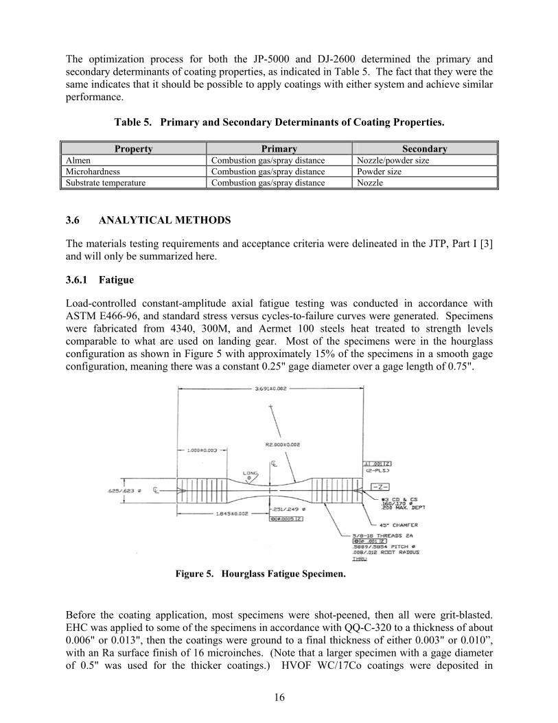
Load-controlled constant-amplitude axial fatigue testing was conducted in accordance with ASTM E466-96, and standard stress versus cycles-to-failure curves were generated. Specimens were fabricated from 4340, 300M, and Aermet 100 steels heat treated to strength levels comparable to what are used on landing gear. Most of the specimens were in the hourglass configuration as shown in Figure 5 with approximately 15% of the specimens in a smooth gage configuration, meaning there was a constant 0.25" gage diameter over a gage length of 0.75".
Before the coating application, most specimens were shot-peened, then all were grit-blasted. EHC was applied to some of the specimens in accordance with QQ-C-320 to a thickness of about 0.006" or 0.013", then the coatings were ground to a final thickness of either 0.003" or 0.010”, with an Ra surface finish of 16 microinches. (Note that a larger specimen with a gage diameter of 0.5" was used for the thicker coatings.) HVOF WC/17Co coatings were deposited in
Figure 5. Hourglass Fatigue Specimen.

17
accordance with Boeing specification 5851, with modifications as specified in Part I of the JTP [3]. As-deposited and final thicknesses subsequent to grinding were the same as for the EHC coatings, with a final Ra surface finish of 8 microinches. Most of the fatigue measurements were conducted in air with some conducted in a 3.5% NaCl solution. A total of 720 specimens were tested, with each series of tests involving five specimens tested at four stress levels. Most tests were conducted with an R-ratio of -1, meaning that the maximum applied stress alternated between tension and compression (e.g., if the maximum stress was 150 ksi, a plot of stress versus time would be a sine wave with maximum amplitude at 150 ksi in tension and minimum amplitude at 150 ksi in compression). Some tests were conducted at R = 0.1 for which the specimens were constantly in tension alternating between the maximum stress and 10% of the maximum stress.
3.6.2 Corrosion
The two types of corrosion tests performed were ASTM B117 salt fog and GM9540P/B cyclic. Although these tests usually involve flat plate specimens, cylindrical specimens were specified for the Landing Gear JTP, as shown in Figure 6. Specimens were fabricated from 4340, 300M, and Aermet 100 steels heat treated to strength levels comparable to those used on landing gear. Before the coating application, all specimens were shot-peened and grit-blasted in the areas indicated in Figure 6. EHC and HVOF WC/17Co and WC/10Co4Cr coatings were deposited in accordance with the same specifications and to the same thicknesses as for the fatigue specimens both before and after grinding. For some of the specimens to receive EHC coatings, a sulfamate nickel under layer was first applied to a minimum thickness of 0.0015" in accordance with QQ-N-290. For some EHC coatings, a polystyrene resin impregnation sealer was applied, and for some HVOF coatings, a Metco URS sealer was applied subsequent to coating application and grinding. Uncoated areas were masked using an epoxy coating. A total of 135 specimens were evaluated in B117 tests, and 40 specimens were evaluated in GM9540P/B tests. After 500 and 100 hours of exposure, the specimens were removed from the test chambers, inspected, and photographed. Based on the inspections, a ranking between 0-10 was applied to each specimen in accordance with ASTM B537-70, with 10 being pristine and 0 being heavily corroded.
Not shot peenedapprox 3/4” Mask
1.25”
Coat4.7”
Grit blast 5” + bottom
Figure 6. Schematic of Corrosion Specimen.

18
3.6.3 Wear
Two types of wear tests were conducted, with the first a low-frequency, long-stroke oscillating piston test that simulated piston actuation and the second a high-frequency, short-stroke fretting test that simulated piston dithering or vibration at a given position. The piston test is schematically illustrated in Figure 7, with the oscillating piston fabricated from 4340 steel and coated with EHC, HVOF WC/17Co, or HVOF WC/10Co4Cr, and the bushing fabricated from 4340 steel, Al-Ni bronze, anodized 2024-T3 Al alloy, a Nitrile seal or a Karon B seal. The fretting test is illustrated in Figure 8, with the shoe fabricated from 4340 steel and coated with EHC, WC/17Co or WC/10Co4Cr and the block fabricated from 4340 steel or nitrile seals in 4340 steel. In the piston test a side load of 72 or 288 pounds was applied and in the fretting test a normal load of 72 or 288 pounds was applied. Coating thicknesses were either 0.003” or 0.010” subsequent to grinding, with an Ra surface finish of 16 microinches for the EHC coatings and 8 microinches for the HVOF coatings. (The smoother finish for HVOF was based upon prior field experience and hydraulic testing.) Because of the large number of potential coating/ mating-surface combinations, the execution of the testing was conducted in accordance with a DOE methodology.
3.6.4 Impact
Two types of impact testing were conducted, with the first designated as gravelometry in which a stream of gravel was fed into an air jet, striking the specimen at variable angles. The second type involved dropping a hardened steel ball onto the specimen. The gravelometer testing was conducted in accordance with ASTM D3170 with a gravel size of approximately 10 mm and a velocity of 200 mph. No specific standards were followed for the dropped-ball tests, but they generally followed a method used by NADEP-JAX and consisted of dropping a 1-7/8"-diameter 52100 steel ball weighing 0.97 pounds from heights ranging from 24" to 102". Specimens consisted of 1"-diameter 4340 steel rods heat-treated for maximum hardness. EHC, HVOF WC/17Co, or HVOF WC/10Co4Cr coatings were applied to the specimens such that the final thicknesses subsequent to grinding were either 0.003" or 0.010". The Ra surface finish for the EHC coatings was 16 microinches, and the surface finish for the HVOF coatings was 8 microinches. Coating surfaces following gravelometer testing were evaluated visually under a microscope, tactilely, and with a surface profilometer. Coating surfaces following dropped ball testing were evaluated visually under a microscope.
Block
Oscillating Motion
Shoe
LOAD
Figure 8. Cross-Sectional Schematic of
Fretting Wear Test.
G u id e
O s c illa t in g p is to n
L o a d
T e s tb u s h in g G u id e
Figure 7. Cross-Sectional Schematic of
Piston and Bushing Oscillating Wear Test.

19
3.6.5 Hydrogen Embrittlement (HE)
Three different sequences of HE testing were conducted: (1) to determine if the HVOF process causes HE, (2) to determine if hydrogen can permeate through HVOF coatings permitting areas adjacent to the HVOF coatings to be electroplated and baked out, and (3) to determine whether HVOF-coated steel is more or less sensitive to environmental HE (also called re-embrittlement) than chrome-plated steel. Specimens in this study were ASTM F519, Type 1a.2 notched bars fabricated from 4340 steel with a notch tensile strength (NTS) of 373 ksi. A representative specimen in shown in Figure 9. EHC, HVOF WC/17Co, or HVOF WC/10Co4Cr coatings were applied to the specimens such that the thicknesses were either 0.003" or 0.010". No grinding of the coatings was performed for test sequences 1 and 2; in sequence 3 the coatings were ground to an Ra finish of 16 microinches except in the notch itself. For sequence 2, in order to charge the specimen with hydrogen, the entire specimen was coated with bright cadmium plating, then the cadmium was stripped in the gauge section without baking. Within 6 hours of removing the cadmium, the HVOF coatings were applied over the gauge section. Tests for sequences 1 and 2 were run in air under a static load of 75% of NTS. Tests for sequence 3 were run in either de-ionized (DI) water or a 5% NaCl solution under a static load of 45% of NTS. Time-to-failure was recorded for each test.
Figure 9. F-519, Type 1a.2 Specimen Coated with 0.010" WC/17Co.

This page left blank intentionally.

21
4.0 PERFORMANCE ASSESSMENT
4.1 PERFORMANCE CRITERIA
The performance criteria for all the materials and component testing are delineated in Section 3.1. For all materials testing, the essential criterion was that the performance of specimens coated with HVOF WC/17Co (and in some cases WC/10Co4Cr) was equivalent or superior to the performance of identical specimens coated with EHC. For fatigue in particular, it is well known that the application of EHC coatings degrades the fatigue performance of high-strength steels. So the issue was whether the HVOF coatings would degrade the performance to a lesser extent or, hopefully, not degrade it at all. Acceptance criteria for rig tests conducted on components were that the HVOF coatings did not show any evidence of delamination, cracking, or extensive wear and that the performance was equivalent or superior to what would be expected for EHC in the same rig test. For flight testing, as with the rig tests, the HVOF coatings could not show any evidence of delamination, cracking, or extensive wear, and the performance had to be equivalent or superior to what would be expected in similar flight operations for EHC-coated components.
4.2 PERFORMANCE DATA
All performance data for the materials testing is presented in detail in the JTR [5]. Only selective data and summaries are presented here. For a more detailed discussion, refer to the Environmental Security Technology Certification Program (ESTCP) Final Report [6].
4.2.1 Materials Testing — Fatigue
The fatigue testing examined the comparative performance between specimens coated with EHC and with HVOF WC/17Co under the different conditions of specimen configuration (hourglass and smooth gage), coating thickness (0.003" and 0.010"), and environment (air or NaCl solution). Figure 10 shows the data and S-N curves for 0.003"-thick EHC and WC/17Co coatings on the small 4340 hourglass specimens and 0.010"-thick EHC and WC/17Co coatings on the large hourglass specimens. For any given stress level, the cycles-to-failure are greater for the WC/17Co-coated specimens than for the EHC-coated specimens and, therefore, the performance of the HVOF-coated specimens is superior. Figure 11 shows the data and S-N curves for 0.003"-thick EHC and WC/17Co coatings on the small 4340 hourglass specimens in both air and the NaCl solution. Although the differences are small, it is still apparent that the performance of the HVOF-coated specimens is superior to that of the EHC-coated specimens. This behavior was essentially duplicated for the 300M and Aermet 100 specimens in that the average cycles-to-failure for the HVOF-coated specimens were always at least equal to and usually greater than for the EHC-coated specimens.

22
Figure 10. Fatigue Data for EHC Compared to HVOF WC/17Co in Air on Hourglass Specimens at R = -1.
4340, R = -1, SMALL HOURGLASS SPECIMENAIR VS. NaCl ENVIRONMENT
100
110
120
130
140
150
160
170
180
190
200
1.E+03 1.E+04 1.E+05 1.E+06 1.E+07 1.E+08CYCLES TO FAILURE, Nf
ENG
INEE
RIN
G S
TRES
S M
AX,
KSI
EHC/Air
EHC/Air/FIT
EHC/NaCl
EHC/NaCl/FIT
WCCo/Air
WCCo/Air/FIT
WCCo/NaCl
WCCo/NaCl/FIT
Figure 11. Fatigue Data for EHC Compared to HVOF WC/17Co for .003" Thickness at R = -1
in Air or NaCl Solution.
4340, R = -1, AIRLARGE (0.010"CTNG) VS. SMALL (0.003"CTNG) HOURGLASS
100.0
110.0
120.0
130.0
140.0
150.0
160.0
170.0
180.0
190.0
200.0
1.E+03 1.E+04 1.E+05 1.E+06 1.E+07 1.E+08
CYCLES TO FAILURE, Nf
ENG
INEE
RIN
G S
TRES
S M
AX,
KSI
LgHG/EHC/PeenedLgHG/EHC/FITLgHG/WCCo/PeenedLgHG/WCCo/FITSmHG/EHC/PeenedSmHG/EHC/FITSmHG/WCCo/PeenedSmHG/WCCo/FIT

23
4.2.2 Materials Testing — Corrosion
Figure 12 presents a summary of the results for 1000-hour exposure of the different coated specimens in the B117 salt-fog test. This includes 0.003"- and 0.010"-thick HVOF WC/17Co and WC/10Co4Cr coatings with and without sealer, and 0.003"- and 0.010"-thick EHC coatings with and without the Ni under layer and with and without sealer. In general, the EHC coatings performed better than the HVOF coatings. The use of a sealer did not have an appreciable effect on corrosion performance on either the HVOF or EHC coatings. The use of the Ni under layer on the EHC coatings did improve performance. On those HVOF coatings that had a low protection rating, undercutting of the coating that appeared to start near the top of the specimen was usually observed. The undercutting was caused by corrosion that was initiated at a defect or near where the epoxy coating overlapped the HVOF coating, with corrosion then proceeding along the coating/substrate interface. This corrosion would then cause the HVOF coating to crack and lift off from the substrate.
Although not part of the JTP, 3-year atmospheric corrosion studies were also reported in the JTR [5]. These results were diametrically opposite the B117 results discussed above. In these tests, flat plates fabricated from 4340 steel were coated with 0.004"-thick EHC, WC/17Co, or Tribaloy 400 and then were exposed to the beach environment at the Navy Corrosion Test Facility in Key West, Florida. After 3 years, the specimens were assessed and protection ratings assigned. The average protection rating was 0.6 for the EHC-coated specimens, 1.7 for HVOF Tribaloy 400, and 10 for HVOF WC/17Co. The possible reasons for the significant difference between the B117 and atmospheric tests are discussed in the next section.
4.2.3 Materials Testing — Wear
For all the fretting tests, the amount of wear for the HVOF and EHC coatings was very small and was comparable. It was concluded that this type of test was not particularly well suited for a comparative study between the two types of coatings. For the sliding piston tests, an extensive amount of data was accumulated for different mating conditions and side loads. Figure 13 is an example of some of this data, showing the ranking numbers on the vertical axis based on visual
PROTECTION RATINGS ON 4340 STEEL IN ASTM B 117
0 2 4 6 8 10 12
3mil Cr, No Ni, No Sealer
3mil Cr, Nickel,No Sealer
3mil Cr, No Ni, Sealer
10mil Cr, No Ni, No Sealer
10mil Cr,Nickel, No Sealer
10mil Cr, No Ni, Sealer
3mil WC/Co, No Sealer
3mil WC/Co, Sealer
10mil WC/Co, No Sealer
10mil WC/Co, Sealer
3mil WC/Co/Cr, No Sealer
10mil WC/Co/Cr, No Sealer
Protection Rating
Figure 12. Protection Ratings on 4340 Steel After B117 Testing.

24
observation of wear on the piston for EHC- or WC/17Co-coated pistons sliding against either a 4340 steel bushing or a bushing containing nitrile seals. The identifiers at the bottom of each bar represent the sample number and type of coating, then the mating material, the number of cycles of the piston, and the side load in pounds. It can be seen that the wear on the WC/17Co-coated pistons was significantly less than that on the EHC-coated pistons. Overall, piston wear tended to be less for HVOF coatings than for EHC, but bushing or seal wear tended to be higher. No significant difference was observed between the WC/17Co and WC/10Co4Cr coatings.
4.2.4 Materials Testing — Impact
Based on the visual, tactile, and profilometry measurements subsequent to the gravelometer testing, it was concluded that the HVOF coatings were slightly more resistant to damage than the EHC coatings. For the dropped ball tests, 100X micrographs were taken on the impact zones and the extent of generation of circumferential and radial (i.e., parallel to the rod axis) cracks in both types of coatings was assessed. Figure 14 presents the data on circumferential cracks measured
0
1
2
3
4
5
6
7
8
9
10
66A-E
HC/NITRILE/240
K/72
66B-E
HC/NITRILE/240
K/72
65A-E
HC/NITRILE/80K
/288
65B-E
HC/NITRILE/80K
/288
68A-W
CCo/NITRILE/24
0K/288
68B-W
CCo/NITRILE/24
0K/288
67A-W
CCo/NITRILE/80
K/72
67B-W
CCo/NITRILE/80
K/72
50A-E
HC/4340/2
40K/28
8
50B-E
HC/4340/2
40K/28
8
49A-E
HC/4340/8
0K/72
49B-E
HC/4340/8
0K/72
53A-W
CCo/4340/8
0K/28
8
53B-W
CCo/4340/8
0K/28
8
54A-W
CCo/4340/2
40K/72
54B-W
CCo/4340/2
40K/72
Visual
Nitrile Seals Metal Bushing
EHC
EHC
WC-Co
WC-Co
Cr 2
4
WC
-Co
24
WC
-CoC
r 24
Cr 6
0
WC
-Co
60
WC
-CoC
r 60
Cr 1
02
WC
-Co
102
WC
-CoC
r 102
0 .003"0 .010"
0
1
2
3
4
5
6
7
# circumferential
cracks
Figure 13. Visual Rankings for EHC- and WC/17Co-Coated Pistons Sliding Against Nitrile Seals and 4340 Steel Bushings. (Ranking from 0 [no wear] to 10 [extensive damage].)
Figure 14. Circumferential Cracking Around Impact Point for 0.003" and 0.010" Coatings at Ball Drop Heights of 24", 60" and 102".

25
around the impact points for 0.003" and 0.010" EHC, WC/17Co and WC/10Co4Cr coatings at ball drop heights of 24", 60", and 102". It can be seen that cracking is more extensive with the EHC coatings. The number of cracks increases with drop height, with the increase more significant on EHC than on HVOF coatings. There were several radial cracks observed with the EHC coatings, but no radial cracks on the HVOF coatings.
4.2.5 Materials Testing — Hydrogen Embrittlement
For the Sequence 1 testing, it was determined that application of the HVOF coatings did not induce HE in high-strength steels (as chrome plating does). The results of the Sequence 2 testing were somewhat inconclusive in that many of the specimens that were not baked failed at the ends rather than in the notch. With baking, most of the specimens passed the test and those that did not failed at the end. Figure 15 presents the results for the Sequence 3 testing, showing that the EHC-coated specimens failed much sooner than the HVOF-coated specimens. Coating thickness had no significant effect on time to failure, and the WC/10Co4Cr coatings had slightly increased time-to-failure than WC/17Co.
4.2.6 Component Testing — Rig Tests
There were two component rig tests that were still ongoing at the time this report was written. The first was an evaluation of an F/A-18 E/F NLG assembly at Messier-Dowty in Canada on which the pistons, axle journals, and pins that normally would be EHC-coated instead had 0.003"-thick HVOF WC/10Co4Cr coatings applied. Figure 16 shows the completed assembly with the HVOF-coated components. Significant delays were encountered in building the test rig and initiating the test, which was divided into two parts. The first involved an evaluation of the drag brace, and the second was a full-spectrum fatigue test of the entire assembly. As of March 2003, the drag brace test had been completed and visual inspection of the HVOF-coated piston and its mating surface indicated no evidence of coating delamination or wear and overall better performance by the HVOF coating than that expected from EHC. The second rig test was an evaluation of a P3 MLG assembly at Lockheed Martin in Marietta, Georgia, on which the piston and axle journals that normally would be EHC-coated instead had
None
EHC,
0.0
03?
WC-C
o, 0
.003
?
WC-C
o-Cr
, 0.0
03?
EHC,
0.0
10?
WC-C
o, 0
.010
?
WC-C
o-Cr
, 0.0
10?
NaCl not scribedNaCl scribed
DI H2O not scribedDI H2O scribed
0.0
10.0
20.0
30.0
40.0
Avg hours to failure
Figure 15. Sequence 3 Time-to-Failure Data Summary.

26
0.003"-thick HVOF WC/17Co coatings applied. The assembly was mounted as the left-hand MLG on a full-scale mockup of the fuselage of the P3. Figure 17 shows the MLG assembly with the HVOF coatings mounted in the test rig. An assembly with EHC-coated components was mounted as the right-hand MLG. The rig test applied stresses to the MLG assemblies that would be expected to be encountered in service and ran for a total of 26,000 cumulative test hours. As of March 2003, the test had been completed but the MLG assembly had not been disassembled for detailed inspection. Visual inspection indicated that the HVOF coatings were in the same condition as when first installed, with no evidence of coating delamination or wear.
4.2.7 Component Testing — Flight Tests
Flight testing has been conducted on a P3 MLG piston installed on aircraft operating in Squadron VP-30. The piston was coated with HVOF WC/17Co to a thickness of 0.003" subsequent to grinding to an Ra surface finish of 8 microinches and was initially installed on Aircraft No. 15622 in April 1999. In August 2000, after 850 landings, the MLG assembly was removed from service due to an oil leak not related to the HVOF coating. The MLG was repaired and was installed on Aircraft 160284 and put back into operation in April 2001. As of March 2003, the MLG assembly has more than 1800 landings. Visual inspection of the HVOF coating indicated no evidence of delamination or wear.
4.3 DATA EVALUATION
Fatigue was established as the most important materials property for qualification of the HVOF WC/17Co coatings as a replacement for EHC on high-strength steels used for landing gear. Based on the extensive amount of testing conducted in this project, it can be concluded that the HVOF coatings did not degrade fatigue performance as much as EHC and, in some cases, did not degrade the performance at all over noncoated steel. However, the fatigue testing did identify a coating integrity issue in which spalling of the HVOF coatings is sometimes observed under fully reversed loading near the yield stress of the steel. This effect is more pronounced for thicker coatings. Additional studies conducted by HCAT determined that in pure axial, fully-reversed loading on 4340 steel with an ultimate tensile strength of 280 thousand pounds per square inch (ksi) and a yield of 230 ksi, spalling of 0.003"-thick WC/17Co coatings can be
Figure 17. P3 Main Landing Gear Assembly with HVOF WC/17Co-Coated Components Mounted in
Test Rig.
Figure 16. F/A-18 E/F Nose Landing Gear
Assembly with HVOF WC/10Co4Cr-Coated Components Prior to Mounting in Test Rig at
Messier-Dowty.
27
observed above 190 ksi and spalling of 0.010"-thick WC/17Co coatings can be observed above 170 ksi. To determine if this effect would impact the application of these coatings on Air Force landing gear, Hill AFB conducted additional studies on actual A10 NLG pistons in which the pistons were coated with WC/17Co to varying thicknesses and subjected to bending stresses. These studies indicated that the integrity of 0.010"-thick coatings was retained in bending up to a maximum stress of 240 ksi at R = -0.33, which is above the stress levels encountered by Air Force landing gear and above the yield stress. Therefore, this provided the Air Force with confidence that they could proceed with implementation of HVOF coatings on landing gear. As indicated in the previous section, the results of the B117 salt-fog corrosion testing were in direct contradiction to the results for the 3-year atmospheric corrosion tests. Boeing St. Louis noted that the corrosion performance of the EHC appeared to be much better than their production experience. To address this issue, Boeing conducted B117 testing on steel panels coated to the same specification with EHC from two different Boeing-qualified vendors. They found the performance of the EHC coatings drastically different, with rust appearing on the specimens from Vendor A within 24 hours and no rust appearing on specimens from Vendor B in 1 week. There was no clear explanation for the difference. It was verified that EHC coatings from Vendor B were used as the baseline for the corrosion testing done in this project. Although the exact reason for the undercutting of the HVOF coatings in the B117 testing has not been determined, their overall performance was still equivalent to the EHC coatings provided by Vendor A in the Boeing tests. Coupled with the favorable results of the atmospheric corrosion testing that provides a high level of confidence that the HVOF coatings will perform as well as if not better than EHC in service. The corrosion mechanism for WC/Co is loss of the Co matrix, whereas EHC corrodes by liquid penetration and undercutting. In some applications, such as hydraulic rods, this could lead to surface roughening and seal leakage, and for those applications, WC/10Co4Cr is preferable provided stresses are not excessive. For the sliding wear tests involving a coated piston mated against a bushing material, overall the wear on the HVOF coatings tended to be less than on EHC coatings, but bushing or seal wear tended to be somewhat higher against the HVOF coatings, which were only ground to an Ra surface finish of 8 microinches. It has been found in other studies that superfinishing WC/17Co coatings to a surface finish of less than 4 microinches will usually improve the performance of seal materials mated against the coating, providing performance superior to that of ground chrome. The gravelometer and ball-drop impact tests clearly showed that the HVOF WC/17Co and WC/10Co4Cr coatings will most likely be less sensitive than EHC to damage caused by dropped tools or debris thrown up from the runway. This is likely to lessen the frequency of intermediate-level repair due to this type of damage. The HE testing clearly showed that the HVOF process itself does not induce embrittlement in high-strength steels and, although the results were somewhat inconsistent, it appears that hydrogen will be able to diffuse out through the WC/17Co and WC/10Co4Cr coatings. Thus, it should be possible to strip and electroplate areas adjacent to HVOF coatings without trapping the hydrogen and creating an embrittlement problem. The re-embrittlement testing showed that use of the HVOF coatings in place of EHC should reduce both post-maintenance HE failure and subsequent stress-corrosion failure in service. This is very important since environmental embrittlement (or stress-corrosion cracking) is a major (and unpredictable) failure mechanism for landing gear.

28
The apparently successful P3 rig and flight tests indicate that the HVOF WC/17Co coatings should be qualified for application on this and similar aircraft. The fact that no corrosion problems have been encountered on the piston in the flight test after more than 3 years of service is particularly noteworthy.

29
5.0 COST ASSESSMENT
5.1 COST REPORTING
A detailed CBA was conducted at a facility that performs overhaul of military aircraft landing gear [7]. Data collection at the facility and financial analyses of the data were performed using the JG PP Environmental Cost Analysis Methodology (ECAM) [8]. In accordance with this methodology, baseline process flow diagrams associated with current hard chrome electroplating processes were developed (see Figure 18), based on information provided by the facility. In general, each of the repaired and overhauled landing gear components addressed in this CBA requires two plating steps (shown as “Repeat as needed” in Figure 18). Rework steps are shown because some components may be improperly coated and require stripping and replating.
Data collection forms were developed to collect information on the baseline hard chrome electroplating operations. A site visit was performed February 1-2, 2000, to collect the data and to conduct interviews with plating engineers, plating operators, plating supervisors, chemists, and other employees throughout the facility. The information gathered during the site visit was supplemented with correspondence after the visit. Where available, material usage rates and costs, labor hours, and waste treatment and disposal costs were identified. Where data were not available, values were assumed based on data from other facilities and engineering judgment.
ChromePlate
Clean
Mask
HotRinse
Grind/ Polish
De-MaskRinse
Strip(chemical)
AbrasiveBlast
Inspect
Rep
eat a
s nee
ded
AcceptableParts
Rew
ork
as n
eede
dUnacceptable
Parts
PartsInspectDetailed
Inspection Mask De-mask
ShotPeen
BakeDry
PlateReq’d
Plate Not Req’d
Figure 18. Process Flow of Hard Chrome Electroplating at Landing Gear
Overhaul Facility.

30
Environmental, safety, and occupational health (ESOH) activity costs were also obtained where available, or estimated. Some costs that may be associated with ESOH activities are listed below. • Lost productivity from worker exposure to the HazMats associated with hard chrome
electroplating and from the use of personal protective equipment (PPE) • Maintaining an accumulation point for waste • Purchasing and maintaining PPE • Purchasing and storing drums, labels, and shipping materials associated with waste • Heating and cooling air from losses due to hoods used for the chrome plating tanks. The collected operating information was used to estimate the potential financial impact of the project, in accordance with the JG-PP CBA methodology. A process flow diagram relating to the application of WC/Co or WC/CoCr by HVOF thermal spraying was also developed to aid in analysis of the data. A generic process flow diagram for HVOF WC/Co and WC/CoCr is shown in Figure 19. Note that five process steps (rinse, clean, hot rinse, dry, and bake) are expected to be eliminated when transitioning from hard chrome electroplating to HVOF thermal spraying.
The approximate number of landing gear components that are hard chrome electroplated annually at the facility include 500 MLG pistons, 250 NLG pistons, and 250 NLG cylinders. This number does not include rework of components; the actual number of components processed may be larger. Workloads can vary from year to year, but the values were considered to be representative of a standard annual workload at the facility. Based on the annual chromic acid usage, it was estimated that the facility uses approximately 13,000 pounds of chromic acid each year for hard chrome electroplating the affected areas on the landing gear components. Affected areas of the components, which are areas that are forecast for transitioning from hard chrome electroplating to HVOF thermal spraying for the purposes of
HVOFSprayMask
Grind/ PolishDe-Mask
Strip(electrochemical)
AbrasiveBlast
Inspect
Rep
eat
as n
eede
d
AcceptableParts
Rew
ork
as n
eede
dUnacceptable
Parts
Parts InspectDetailedInspection
Mask De-mask
ShotPeen
HVOFReq’d
HVOF Not Req’d
Figure 19. Projected Process Flow of HVOF for Applying WC/Co or WC/CoCr.

31
this CBA, are shown in Figure 20 for the MLG piston. Similar areas will be on the other components. These parts were selected as likely components for transitioning because they have the largest external chrome plated surfaces suitable for transitioning to HVOF coatings. Additionally, these components require stripping and replating at a relatively high rate during the overhaul process.
Noted below is some of the key data obtained from the facility related to current EHC plating operations. • Labor requirements and turnaround time (TAT) for each of the EHC plating steps
indicated in Figure 18. • Labor requirements for maintenance of the chrome plating baths. • Types of inputs (i.e., materials, energy, and labor) and outputs (e.g., air emissions,
wastewater, and hazardous waste) associated with EHC process. • Average EHC plating thickness for repaired components is 0.010" (before grinding). • Material usage and costs for chromic acid, lead anodes, NaOH, maskants, etc. • Energy usage related to HE relief baking. • Types, quantities, and costs of PPE used for electroplating activities. • Laboratory tests associated with process control.
Figure 20. Main Landing Gear Piston: Areas Expected to Be
Transitioned from Hard Chrome Electroplating to HVOF Thermal Spraying.

32
• Labor requirements for metallurgical tests. • Annual costs associated with treatment of wastewater and sludge disposal. Some of the main assumptions associated with transitioning to HVOF included the following. • If HVOF is implemented, two chrome plating tanks and one chrome stripping tank could
be shut down. • HVOF coatings would be applied to the same thickness as EHC coatings. • WC/17Co and WC/10Co4Cr powder costs would be $32 per pound. • The HVOF spraying rate would be 10 pounds per hour with a deposit efficiency of 50%. • On average, one HVOF spray cell could process on landing gear component in 40
minutes. • Current electroplating labor rates are $65 per hour and the labor rates for HVOF would
remain the same. • Peening, grinding, and inspection steps would remain essentially constant; the
requirement for more expensive diamond grinding wheels would be offset by their longer service life.
• The annual quantity of landing gear components processed would remain constant. • Approximately 88% of the total surface area currently EHC-coated could be transitioned
to HVOF; the remaining 12% cannot be transitioned due to line-of-sight issues. Based on the materials testing conducted, it was projected that the useful lifetime of a landing gear component coated with WC/17Co or WC/10Co4Cr would be 50-100% longer than for a component coated with EHC. However, the effects of increasing the useful lifetime were not considered in this CBA. It was determined that the average TAT for landing gear components coated with HVOF would be approximately 5 days less than the average TAT for EHC-plated components.
5.2 COST ANALYSIS
Data and assumptions described in Section 5.1 were used to calculate the current annual operating costs for coating the landing gear components using the baseline hard chrome electroplating process and estimating the costs for coating the components with HVOF. The annual operating cost avoidances reported in this section were derived from comparing the operating costs of the baseline hard chrome electroplating process to those calculated for the HVOF equipment and two types of coatings, WC/17Co and WC/10Co4Cr. Table 6 shows the average annual operating cost avoidances that were estimated for implementing HVOF to replace hard chrome electroplating of the landing gear components at the facility. It is expected that the average number of landing gear that need to be repaired and

33
overhauled will decrease beginning in the eighth year after implementation because of superior performance and durability of the WC/Co or WC/CoCr coatings. However, the facility did not want to include these cost savings because they are not sure when the coating will be proven enough to decrease their refabrication schedule.
Table 6. Estimated Annual Operating Cost Avoidance for Landing Gear Overhaul Facility.
Annual Operating Cost Avoidancea
Labor $113,540 Materials $75,520 Utilitiesb $11,390 Waste disposal $2,900 Additional cost avoidance due to reduced TAT $32,880 Total $236,230
a Based on 1,250 per year total components processed and 1,700 in2 of the three components electroplated; after HVOF implementation assumes 1,500 in2 HVOF coated and 200 in2 electroplated.
b Average of equipment and material types To measure the financial viability of this project, three performance measures for investment opportunities were used: net present value (NPV), internal rate-of-return (IRR), and payback period. The NPV is the difference between capital investments and the present value of future annual cost benefits associated with the alternatives. The IRR is the discount rate at which NPV is equal to zero. NPV and IRR account for the time value of money and discount the future capital investments or annual cost benefits to the current year. The payback period is the time period required to recover all the capital investment with future cost avoidance. For NPV and IRR, a 3.2% discount rate was used for this financial evaluation, which is consistent with the Office of Management and Budget (OMB) Circular Number A-94 and the ECAM. A summary of the financial evaluation for implementing HVOF to replace hard chrome electroplating of the landing gear components is shown in Table 7. This financial evaluation includes the range of annual operating cost benefits and the NPV based on a 15-year study period. The evaluation summarized in Table 7 does not include the costs of validation testing. The 15-year NPV for the surveyed facility ranges from $1,799,700 to $1,977,500. The actual savings achieved at other facilities will vary depending on the number of actual applications converted, future workloads, and other factors specific to each facility.
Table 7. Results of 15-Year Financial Evaluation for Implementation of HVOF.
Category Calculated Result Annual operating cost avoidance $195,600 - $210,700 Initial capital investment $700,450 Net present valuea $1,799,700 - $1,977,500 Internal rate of returna 30.5 - 32.8% Discount paybacka 3,29 - 3,53 years
a This value was calculated with Pollution Prevention Financial Analysis and Cost Evaluation System (P2/FINANCE) software program. This software program is proprietary and copyrighted by Tellus Institute of Boston, Massachusetts. A 15-year analysis and 3.2% discount rate were assumed.

This page left blank intentionally.

35
6.0 IMPLEMENTATION ISSUES
6.1 COST OBSERVATIONS
The annual operating cost savings at a major landing gear overhaul facility ranges from $195,600 to $210,700 for replacing 88% of its chrome plating operations with HVOF thermal spraying. Payback on the capital investment of installing HVOF systems would be realized in approximately 3½ years. Although the annual operating costs for both EHC and HVOF would be different at other facilities based on labor rates, types of equipment used, and other factors, substantial savings could still be anticipated by replacing as much of their chrome plating operations as possible with HVOF. Additional cost savings that would be realized are associated with the estimated 50-100% extension of service life for the WC/Co or WC/CoCr coatings over EHC coatings. In the future, as HVOF-coated landing gear components come into the facility for inspection, fewer will require overhaul than would be expected with EHC coatings. Labor and material costs associated with overhaul operations will be reduced since the components could be returned to service. In addition, the elimination of process HE and the reduction of environmental embrittlement will reduce the risk (and therefore the annual cost) of landing gear service failures. It should also be mentioned that the CBA described in Section 5 did not take into account any increases in costs associated with EHC resulting from more stringent environmental or worker safety regulations. If, for example, the PEL for hexavalent chromium were reduced, as is expected, the cost for chrome plating would increase, thereby making the operating cost savings even greater for HVOF. Although not discussed in Section 5, a cost analysis was performed to determine if outsourcing the HVOF coating operations to a job shop would be more cost-effective. The results showed that it would be less costly to establish an in-house HVOF coating capability. Therefore, the facility for which the CBA was performed has decided to acquire and install HVOF systems in its repair shop to process landing gear components.
6.2 PERFORMANCE OBSERVATIONS
Based on all the materials testing, it was concluded that on high-strength steels that are used to fabricate landing gear components, the fatigue, wear, and impact-resistant properties of the HVOF WC/17Co and WC/10Co4Cr coatings are superior to those of EHC coatings. Inconsistent results were obtained for corrosion testing of both the HVOF and EHC coatings, but the B117 salt-fog and atmospheric corrosion test results, together with the favorable performance of WC/17Co coatings in service on the P3 aircraft, conclude that the HVOF coatings should perform at least as well as EHC coatings. There are no HE issues associated with HVOF coatings, and the testing indicated that re-embrittlement is less of an issue with HVOF coatings than with EHC. All the rig and flight testing performed to date has indicated excellent performance of the WC/17Co and WC/10Co4Cr coatings. The one issue that still can impact implementation of the HVOF coatings on landing gear components is delamination at high stresses and strains. It has been shown that the delamination is dependent on the thickness of the coating and on how the stresses are applied. Thus, for example, on a hollow cylinder representative of a landing gear piston, a WC/17Co coating will remain intact in tension/compression bending (R = -0.33) to beyond the yield stress of the base

36
material whereas it will delaminate at about 80% of the yield stress (for a 0.010"-thick coating) for fully-reversed tension/compression stresses applied axially. The Air Force believes that the bending test is more representative of real-life stresses applied to landing gear and is continuing to implement HVOF coatings on landing gear components. On the other hand, Navy structural engineers believe that the HVOF coatings should be able to remain intact up to the yield stress for fully-reversed axially applied stress and therefore are reluctant to approve the coatings on carrier-based aircraft that are subjected to high stress. But this concern should not prevent implementation of the HVOF coatings on land-based aircraft and helicopters.
6.3 SCALE-UP ISSUES
The HVOF systems currently in operation at OO-ALC and NADEP-JAX are full-production systems with fixturing for manipulation of various types of components and robots on which the HVOF spray guns are mounted. The only issue is the number of spray booths required to replace all of the chrome plating operations for which HVOF is amenable. OO-ALC is projecting a total of 10 spray booths, four considered small, four medium, and two large for processing different size components. These spray booths would be used for processing more than just landing gear components as most of the actuators on Air Force aircraft are also processed at Ogden. NADEP-JAX has not projected the total number of spray booths required but does plan to acquire more as the number of components approved for HVOF processing increases.
6.4 OTHER SIGNIFICANT OBSERVATIONS
The Air Force is proceeding with implementation of HVOF coatings on landing gear components. As of March 2003, a project implementation team established at OO-ALC expects a phased transition based on capacity. They have approved the application of WC/17Co and WC/10Co4Cr coatings up to 0.010" thickness on the following components:
C-5 MLG outer pitch actuator C-5 MLG ball screw F-16 MLG axle A-10 NLG inner piston KC-135 MLG forward axle F-15 brake drive keys
C-5 gudgeon pin F-16 MGL tension strut A-10 NLG charging pin KC-135 MLG aft axle KC-135 NLG piston B-2 rub strips
Fixturing is being developed for spraying these parts, and the coatings will be applied under local engineering authority.
6.5 LESSONS LEARNED
In attempting to qualify and implement a new technology on flight-critical components, it is essential to involve the entire stakeholder community from the outset and identify important areas of concern. Program offices, system support offices, depot engineers, and OEMs contributed to the development of the JTPs, and all results—positive and negative—were presented to them for evaluation and consideration. When an unexpected issue arose, such as the delamination of the HVOF coatings at high stress, it was again important to involve the stakeholder community and obtain their criteria for acceptable performance. There must be flexibility (both programmatic and financial) built into any project of this type so unplanned testing can be conducted to address unforeseen issues.

37
6.6 END USER/OEM ISSUES
One of the key end user/OEM issues is the availability of standards and specifications related to the powder used for HVOF coatings, application procedures for the coatings, and grinding procedures for the coatings. The HCAT has worked with the SAE Aerospace Metals Engineering Committee to develop four separate specifications in these areas. Those related to powder and coating deposition were completed and forwarded to SAE Aerospace Materials Committee B, who approved them in February 2003. The following are the designations:
AMS 2448 – “Application of Tungsten Carbide Coatings on Ultra-High-Strength Steels, High-Velocity Oxygen/Fuel Process” AMS 7881 – “Tungsten Carbide-Cobalt Powder, Agglomerated and Sintered” AMS 7882 – “Tungsten Carbide-Cobalt Chromium Powder, Agglomerated and Sintered”
A specification for grinding and superfinishing the coatings has been drafted and is in the approval process. All these specifications can now be utilized by any manufacturing or overhaul depot, resulting in consistency between facilities with respect to coating properties.
6.7 APPROACH TO REGULATORY COMPLIANCE AND ACCEPTANCE
The principal environmental and worker safety issues associated with HVOF thermal spraying are air emissions containing overspray particles and the noise of the gun itself. All the depots involved in the HCAT project already had other types of thermal spray equipment in operation, such as flame or plasma spray and therefore had the appropriate air handling equipment (e.g., exhaust hoods, bag houses) available and also had the appropriate air permits to cover operation of the HVOF systems. All the HVOF systems are installed in soundproof booths and are computer-controlled, so no operator is exposed to the noise of the HVOF gun.

This page left blank intentionally.

39
7.0 REFERENCES
1. “High Velocity Oxy Fuel Final Results Report,” Final Report issued by Science Applications International Corporation under Government Contract F09603-90-D2215, Oklahoma City Air Logistics Center, Tinker Air Force Base, May 25, 1994.
2. “Hard Chrome Coatings: Advanced Technology for Waste Elimination,” Final Report
issued by Northwestern University, Evanston, IL, under DARPA Contract MDA972-93-1-0006, 1996.
3. “Joint Test Protocol, Validation of WC/Co and WC/CoCr HVOF Thermal Spray
Coatings as a Replacement for Hard Chrome Plating on Aircraft Landing Gear, Part I: Materials Testing.” Prepared by Hard Chrome Alternatives Team for Environmental Security Technology Certification Program. Revision A, September 1999.
4. “Joint Test Protocol, Validation of WC/Co and WC/CoCr HVOF Thermal Spray
Coatings as a Replacement for Hard Chrome Plating on Aircraft Landing Gear, Part II: Operational Testing.” Prepared by Hard Chrome Alternatives Team for Environmental Security Technology Certification Program. September 2000 (draft).
5. “Joint Test Report, Validation of WC/Co and WC/CoCr HVOF Thermal Spray Coatings
as a Replacement for Hard Chrome Plating on Aircraft Landing Gear, Part I: Materials Testing.” Prepared by Hard Chrome Alternatives Team for Environmental Security Technology Certification Program. November 2002.
6. ESTCP Final Report. “Validation of WC/Co and WC/CoCr HVOF Thermal Spray
Coatings as a Replacement for Hard Chrome Plating on Aircraft Landing Gear,” Naval Research Laboratory, Washington, DC 20375. May 2003.
7. “Final Cost Benefit Analysis S-98-MF-011-C for Validation of WC/Co and WC/CoCr
HVOF Thermal Spray Coatings as a Replacement for Hard Chrome Plating on Aircraft Landing Gear.” Prepared by National Defense Center for Environmental Excellence for the Joint Group on Pollution Prevention. September 2002.
8. “Environmental Cost Analysis Methodology (ECAM) Handbook.” Environmental
Security Technology Certification Program Validation Tasks. Contract No. DAAA21-93-C-0046. Task No. 098, CDRL No. A013. Concurrent Technologies Corporation. March 1999.

This page left blank intentionally.
A-1
APPENDIX A
POINTS OF CONTACT
Name Address Phone/Fax/E-mail Bruce D. Sartwell Naval Research Laboratory
Code 6170 4555 Overlook Avenue, SW Washington, DC 20032
(202) 767-0722 (202) 767-3321 [email protected]
Keith O. Legg Rowan Technology Group 1590 South Milwaukee Avenue, Suite 205 Libertyville, IL 60048
(847) 680-9420 (847) 680-9682 [email protected]

ESTCP Program Office
901 North Stuart StreetSuite 303Arlington, Virginia 22203
(703) 696-2117 (Phone)(703) 696-2114 (Fax)
e-mail: [email protected]