Embed Size (px)
Citation preview
!1C FILE COPY
AD-A211 799
U.S. Army Research Institutefor the Behavioral and Social Sciences
Research Report 1524
MANPRINT Evaluation: AN/TRC-170Digital Troposcatter Radio System
Gregory S. Krohn and Samuel E. Bowser
Essex Corporation
OTIOAM LECTE
AG2 81989,
-.J
June 1989
Approved for public release: distribution is unlimited.
8090.
U.S. ARMY RESEARCH INSTITUTE
FOR THE BEHAVIORAL AND SOCIAL SCIENCES
A Field Operating Agency Under the Jurisdiction
of the Deputy Chief of Staff for Personnel
EDGAR M. JOHNSON JON W. BLADESTechnical Director COL, IN
Commanding
Research accomplished under contractfor the Department of the Army
Essex Corporation
Technical review by
Peter J. LegreeEdward W. Sullivan
NOTICES
D TRIBUTION: mary dis don of this report de by ARI. P ddreco spondence co erning distribu f reports to:)D.S. Army rch Institute r theBeha* ra and S ial Sciences, ATTN: - 001 Eisenhower Alex a, Virgin'2 2333-5 •
FINAL DISPOSITION: This report may be destroyed when it is no longer needed. Please do notreturn it to the U.S. Army Research Institute for the Behavioral and Social Sciences.
NOTE: The findings in this report are not to be construed as an official Department of the Armyposition, unless so designated by other authorized documents.

UNCLASSIFIEDSECURITY CLASSIFICATION OF THIS PAGE
SForm Ap~proved
REPORT DOCUMENTATION PAGE OMBNo. 0704-088
la.REPORT SECURITY CLASSIFICATION lb RESTRICTIVE MARKINGS
Unclassified --
2a. SECURITY CLA.SSIFICATION AUTHORITY 3. DISTRIBUTION /AVAILABILITY OF REPORT-- __Approved for public release;
2b. DECLASSIFICATION/DOWNGRADING SCHEDULE distribution is unlimited.
4. PERFORMING ORGANIZATION REPORT NUMBER(S) S. MONITORING ORGANIZATION REPORT NUMBER(S)
ARI Research Report 1524
6a. NAME OF PERFORMING ORGANIZATION 6b. OFFICE SYMBOL 7a. NAME OF MONITORING ORGANIZATION
Essex Corporation (if applicable) U.S. Army Research InstituteI I - Field Unit at Fort Hood, Texas
6c. ADDRESS (City, State, and ZIP Code) 7b. ADDRESS (City, Stare, and ZIP Code)
741 Lakefield Road, Suite B HQ TEXCOM (PERI-SH)
Westlake Village, CA 91361 Fort Hood, TX 76544-5065
8a. NAME OF FUNDING/SPONSORING 8b. OFFICE SYMBOL 9. PROCUREMENT INSTRUMENT IDENTIFICATION NUMBERORGANIZATION U. S. Army Research (If applicable)
Institute for the Behavioral MDA903-86-C-0341.And Social Sciences I PERI-Sc. ADDRESS (City, State, and ZIP Code) 10. SOURCE OF FUNDING NUMBERS
5001 Eisenhower Avenue PROGRAM PROJECT TASK WORK UNIT
Alexandria, VA 22333-5600 ELEMENT NO. NO. NO. ACCESSION NO.
63739A 793 151 C3
. 11. TITLE (Include Securrty Classification)
MANPRINT Evaluation: AN/TRC-170 Digital Troposcatter Radio System
12. PERSONAL AUTHOR(S)Krohn, Gregory S., and Bowser, Samuel E. (Essex Corporation)
13a. TYPE OF REPORT 13b. TIME COVERED 14. DATE OF REPORT (Year, Month, Day) 15. PAGE COUNTFinal FROM 86/10 TO 88/01 1989, June16. SUPPLEMENTARY NOTATION
Contracting Officer's Represent tive: Charles G. Nyst om
17. COSATI CODES Y18. SUBJECT TERMS (Continue on reverse Kecessary and identify by block number)FIELD GROUP SUB-GROUP Human factors evaluation 5y.stem safety, Manpower,
\,MANPRINT evaluation - Hea hazards, .. "ITroposcatter communications/ Training,
". 19, TRACT (Continue on reverse if necessary and identify by block number) v
This document describes the Manpower and Personnel Integration (MANPRINT) Evaluationf
the AN/TRC-170 Digital Troposcatter Radio System. The MANPRINT evaluation was conducted in
support of the AN!TRC-170 Follow-On Operational Test and Evaluation (FOT&E) by\the U.S.
Army Research Institute for the Behavioral and Social Sciences (ARI). The FOT&E\was con-
ducted by the U.S. Army Operational Test and Evaluation Agency (OTEA) at Fort Huachuca, AZ,
from September 1986 through January 1987. The purpose of the MANPRINT Evaluation was to
identify human factors engineering, system safety, health hazards, training, and manpower
factors leading to refinements in the AN/TRC-170 system. The MANPRINT evaluation methodology
included structured interviews, on-site observations of operations and maintenance, and
measures of task performance times. There were 24 MANPRINT findings involving equipmen
assembly and disassembly, materials handling procedures, and safety during road marches.
20. DISTRIBUTION/AVAILABILITY OF ABSTRACT 21. ABSTRACT SECURITY CLASSIFICATIONMUNCLASSIFIEDUNLIMITED 0 SAME 4S RPT. 0 DTIC USERS Unclassified
22a. NAME OF RESPONSIBLE INDIVIDUAL 22b. TELEPHONE (Include Area Code) 22c. OFFICE SYMBOL
Charles 0. Nystrom (817) 288-9118 PERI-SH
DD Form 1473, JUN 86 Previous editions are obsolete. SECURITY CLASSIFICATION OF THIS PAGEUNCLASSIFIED
Research Report 1524
MANPRINT Evaluation: AN/TRC-170Digital Troposcatter Radio System
Gregory S. Krohn and Samuel E. BowserEssex Corporation
Field Unit at Fort Hood, TexasGeorge M. Gividen, Chief
Systems Research LaboratoryRobin L. Keesee, Director
U.S. Army Research Institute for the Behavioral and Social Sciences5001 Eisenhower Avenue, Alexandria, Virginia 22333-56n0
Office, Deputy Chief of Staff for PersonnelDepartment of the Army
June 1989
Army Project Number Soldier-System Consideration in20263739A793 Force DevelopmentTesting
Approved for public release; distribution is unlimited.
iii

FOREWORD
The primary mission of the Fort Hood Field Unit of the U.S. Army ResearchInstitute for the Behavioral and Social Sciences (ARI) is "to conduct trainingand human performance research and MANPRINT (Manpower and Personnel Integra-tion) assessments of units and systems in an operational environment in orderto develop and expand the MANPRINT data base; support ODCSPER'S responsibil-ities in test and evaluation as outlined in AR 71-2; and support user testsconducted by OTEA, TEXCOM, and the test boards."
The mission technical objectives are to identify and document unresolvedMANPRINT issues and problems experienced by materiel systems undergoing usertesting during the materiel acquisition process; to formulate and recommendcourses of action in the MANPRINT domains of manpower, personnel, and trainingthat will cost-effectively optimize performance of the system under test; andto report other issues and problems identified in user testing to the appro-priate agencies for the MANPRINT domains of human factors engineering, systemssafety, and health hazards.
This report presents the results of the ARI MANPRINT evaluation of theAN/TRC-170 Digital Troposcatter Radio System. The AN/TRC-170 system consistsof radio terminals that transmit microwave signals that are scattered andreflected off the upper atmosphere and received by other terminals. The radioterminals provide a tactical secure multichannel transmission and reception ofanalog and digital signal traffic. Messages originate at corps and echelons-above-corps levels and are sent through the radio terminals for microwavetransmission and reception.
This research is subsumed under the "Soldier-System Considerations inForce Development Testing" task of the "Human Factors in Training andOperational Effectiveness" project. It was conducted in accordance with theprovisions of a Letter of Agreement between the U.S. Army Research Institute(ARI) and the U.S. Army Operational Test and Evaluation Agency (OTEA) dated 15June 1983.
The contents of this MANPRINT report were incorporated into the OTEAAN/TRC-170 Final Test Report and the OTEA Independent Evaluation Report. Theresearch findings and recommendations were briefed by ARI to the OTEA command-ing general, the AN/TRC-170 program manager, and representatives from theAN/TRC-170 TRADOC system manager's office during January 1987. Findingsprovided the basis for recommendations for improving system effectiveness.
E ARM.HO #ON0
Technical Director
v
MANPRINT EVALUATION: AN/TRC-170 DIGITAL TROPOSCATTER RADIO SYSTEM
EXECUTIVE SUMMARY
Requirement:
The AN/TRC-170 was tested in a Follov-On Operational Test and Evaluation(FOT&E) by the U.S. Army Operational Test and Evaluation Agency (OTEA). TheFOT&E was conducted at Fort Huachuca, Arizona, from September 1986 throughJanuary 1987. This report describes the Manpower and Personnel Integration(MANPRINT) evaluation support provided to OTEA during the FOT&E by the U.S.Army Research Institute for the Behavioral and Social Sciences (ARI). Thepurpose of the MANPRINT effort was to identify manpower, personnel, training,human factors engineering, systems safety, and health hazard problems in areaswhere modification would lead to more effective system performance andmaintenance.
Procedure:
Crews and maintainers were observed while performing AN/TRC-170 opera-tional scenarios. Crewman were administered structured interviews afteroperational scenarios were completed. Timed crew task performance measureswere collected and compared to system emplacement criteria. At an end-of-testscoring conference attended by agency representatives participating in thetest, the findings were scored according to their impact on system performanceand their priority for corrections.
Findings:
There were 24 findings of the MANPRINT evaluation. Since the AN/TRC-170operates as a relay node, many of the findings concerned site emplacement anddisemplacement. Most findings involved materials handling difficulties.Four-man crews performed tasks more rapidly than three-man crews; however, thesystem emplacement criteria were still not met.
Utilization of Findings:
The findings in this report were integrated into the OTEA Final TestReport and the OTEA Independent Evaluation Report. The correction ofidentified MANPRINT problems will significantly improve the operationaleffectiveness of the AN/TRC-170 and increase both crew and maintainer safety.
vii
MANPRINT EVALUATION: AN/TRC-170 DIGITAL TROPOSCATTER RADIO SYSTEM
CONTENTS
Page
INTRODUCTION. .. .............................. 1
General. .. ............................... 1Description. .. ..............................
METHOD .. ............. .................... 11
Crew Members........................................................11Evaluation Materials. .............. .. ....... 11Evaluation Procedures .. .... ........ ............. 11
RESULTS. .... ......... ......... ............ 14
Detailed Descriptions of Findings. .. ....... .......... 14Task Performance Measures .. .... ......... ......... 57
DISCUSSION .. ............. .................. 68
REFERENCES .. .............. ................. 69
LIST OF TABLES
Table 1. AN/TRC-170 general operating characteristics .. .... ..... 2
2. Crewmen and maintainer basic demographics .. ........... 12
3. Performance impact rating scale andcorrection priority scale .. ....... ............ 15
4. AN/TRC-170 MANPRINT findings summary. .. ....... ..... 16
5. Task performance time for V2 set up bynumber of persons performing the task. .... ......... 58
6. Task performance time for V2 tear down bynumber of persons performing the task. .... ......... 60
7. Task performance time for V3 set up bynumber of persons performing the task. .... ......... 61
ix
CONTENTS (Continued)
Page
LIST OF TABLES (Continued)
Table 8. Task performance time for V3 tear down bynumber of persons performing the task .. ........... ... 62
9. Proportion of criterial emplacements and meanemployment times with two measures: Elapsedtime and time in criterial tasks ........ ......... ... 67
LIST OF FIGURES
Figure 1. The operational concept of the AN/TRC-170V2 system, showing transmissions reflectedoff the upper atmosphere ......... ................ 3
2. The V2 transport configuration ........ ............. 4
3. The V3 transport configuration ........ ............ 5
4. The emplaced V2 and V3 antennas and shelters ...... 7
5. The mobilizer-mounted V2 S-665 shelter equipmentlayout along the roadside wall .. ................ 8
6. The truck-mounted V3 S-666 shelter equipmentlayout along the roadside wall .. ................ 9
7. The truck-mounted V3 S-666 shelter equipmentlayout along the curbside wall .. ............. ... 10
8. The M-720 mobilizer carrying the S-665 shelter ..... 21
9. The main power panel in the V3 shelter ......... .23
10. The low-profile pallet that was mounted ona 2.5-ton truck and covered for transport .... ........ 27
11. The waveguide latches that were difficult toclose and the O-ring that fell out . ........... .32
12. The waveguide protective container and trailerstowage location ...... .................... ... 33
13. The vaveguides and other cables laid out on theground prior to installation ... .............. ... 34
x
CONTENTS (Continued)
Page
LIST OF FIGURES (Continued)
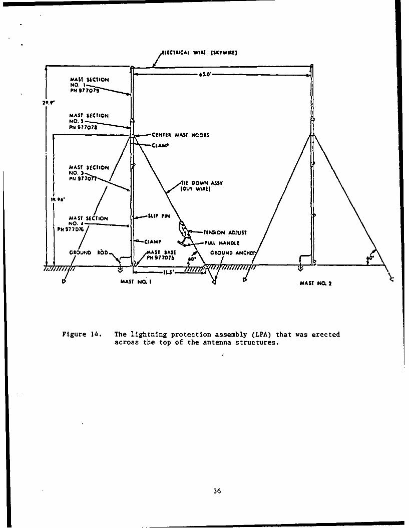
Figure 14. The lightning protection assembly (LPA)that was erected across the top of theantenna structures ....... .................... ... 36
15. A cut-away view of the Pionjar drive motorand of the duckbill anchor .... ................ ... 38
16. An example of the type of pin that wasdifficult to insert and remove ... .............. ... 43
17. The 9.5-ft. antenna, rear truss clamp, andbearing ball ....... ....................... .... 46
18. An example of the type of manipulation taskthat could be performed more rapidly bycrewmen using a stepladder or platform ............ ... 49
19. The 9.5-ft. antenna and hand crank that wasdifficult to use to reach the elevation angleadjustment device ...... .................... ... 50
20. The interior of the low-profile pallet showingthe location of the accessory alignment kit ....... .54
21. The low-profile pallet which was mounted on a2.5-ton truck ....... ...................... ... 56
xi
MANPRINT EVALUATION: AN/TRC-170 DIGITAL TROPOSCATTER RADIO SYSTEM
Introduction
General
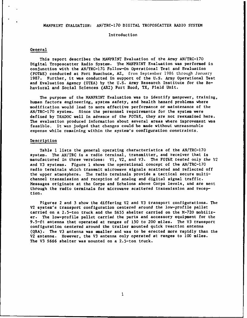
This report describes the MANPRINT Evaluation of the Army AN/TRC-170Digital Troposcatter Radio System. The MANPRINT Evaluation was performed inconjunction with the AN/TRC-170 Follow-On Operational Test and Evaluation(FOT&E) conducted at Fort Huachuca, AZ, from September 1986 through January1987. Further, it was conducted in support of the U.S. Army Operational Testand Evaluation Agency (OTEA) by the U.S. Army Research Institute for the Be-havioral and Social Sciences (ARI) Fort Hood, TX, Field Unit.
The purpose of the MANPRINT Evaluation was to identify manpower, training,human factors engineering, system safety, and health hazard problems wheremodification would lead to more effective performance or maintenance of theAN/TRC-170 system. Since the personnel requirements for the system weredefined by TRADOC well in advance of the FOT&E, they are not reexamined here.The evaluation produced information about several areas where improvement wasfeasible. It was judged that changes could be made without unreasonableexpense while remaining within the system's configuration constraints.
Description
Table 1 lists the general operating characteristics of the AN/TRC-170system. The AN/TRC is a radio terminal, transmitter, and receiver that ismanufactured in three versions: V1, V2, and V3. The FOT&E tested only the V2and V3 systems. Figure 1 shows the operational concept of the AN/TRC-170radio terminals which transmit microwave signals scattered and reflected offthe upper atmosphere. The radio terminals provide a tactical secure multi-channel transmission and reception of analog and digital signal traffic.Messages originate at the Corps and Echelons above Corps levels, and are sentthrough the radio terminals for microwave scattered transmission and recep-tion.
Figures 2 and 3 show the differing V2 and V3 transport configurations. TheV2 system's transport configuration centered around the low-profile palletcarried on a 2.5-ton truck and the S655 shelter carried on the M-720 mobiliz-er. The low-profile pallet carried the parts and accessory equipment for the9.5-ft antenna that operated at ranges of 150 to 200 miles. The V3 transportconfiguration centered around the trailer mounted quick reaction antenna(QRA). The V3 antenna was smaller and was to be erected more rapidly than theV2 antenna. However, the V3 antenna only operated at ranges to 100 miles.The V3 S666 shelter was mounted on a 2.5-ton truck.
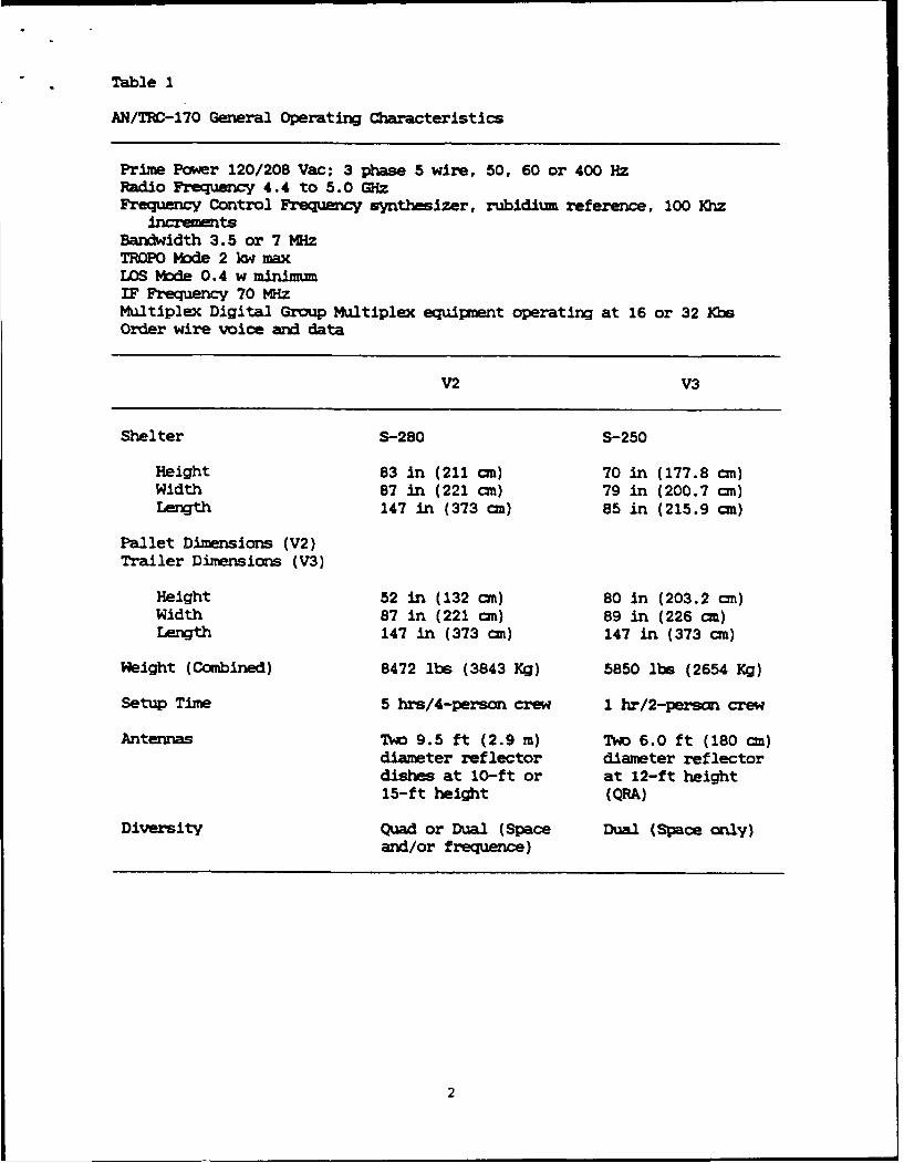
Table 1
AN/TRC-170 General Operating Characteristics
Prime Power 120/208 Vac; 3 phase 5 wire, 50, 60 or 400 HzRadio Frequency 4.4 to 5.0 GHzFrequency Control Frequency synthesizer, rubidium reference, 100 Khz
incrementsBandwidth 3.5 or 7 M~zTROPO Mode 2 kw maxLOS Mode 0.4 w minimumIF Frequency 70 KizMultiplex Digital Group Multiplex equipment operating at 16 or 32 KbsOrder wire voice and data
V2 V3
Shelter S-280 S-250
Height 83 in (211 cm) 70 in (177.8 an)Width 87 in (221 cm) 79 in (200.7 cm)Length 147 in (373 cn) 85 in (215.9 cn)
Pallet Dimensions (V2)Trailer Dimensions (V3)
Height 52 in (132 cm) 80 in (203.2 cm)Width 87 in (221 cm) 89 in (226 cm)Length 147 in (373 cm) 147 in (373 cm)
Weight (Combined) 8472 lbs (3843 Kg) 5850 lbs (2654 Kg)
Setup Time 5 hrs/4-person crew 1 hr/2-person crew
Antennas Two 9.5 ft (2.9 m) Two 6.0 ft (180 cm)diameter reflector diameter reflectordishe at 10-ft or at 12-ft height15-ft height (QRA)
Diversity Quad or Dual (Space Dual (Space only)and/or frequence)

LU 0
>.1 4*4
>U 0LUA
LU 41'
0
- ..4
z -jU)
LU 'U
0 L0
0LU)
LU C
-J-
0
I- 0
~~0-H )
4
4-
04C Q40-4
z0
044

M-720
44 UlANITRC-170is-& 12 /2 TO M-3A2J=V2 0
Fiue2 h V rnpr cniuain
4N M Q 3 0 n L

QUICK REACTION
I~13AN/TRC-170 V3
M-35A2 AN/MJQ-18
2~4TONM-5A2~r GENGE
Figure 3. The V3 transport configuration.
5
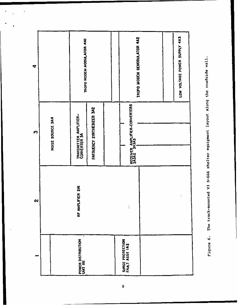
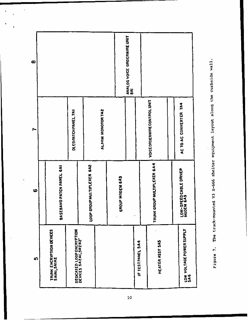
Figure 4 shows the V2 and V3 antennas and shelters as they were deployedin the field. Figure 5 shows the layout of the V2 mobilizer-mounted S-665
shelter. All the radio components were mounted on the roadside (left) wallwhile mobilizer parts, miscellaneous equipment and crewmen basic issue items
(BII) were stowed on the curbside (right) wall. Figure 6 and 7 show the
layout of the V3 truck mounted shelter for the roadside (left) and curbside(right) wall, respectively. During the FOT&E, six V2 models and four V3models were tested.
A special tool supplied to the V2 and V3 crews was a handheld Pionjardrill similar to a Jack hammer. The Pionjar was used to drill holes in soil
for inserting duckbill anchors and to drive in the anchors. The anchor holes
could be drilled to a depth of 5 ft and were used to secure the 9.5-ft V2antenna and the lightening protection assembly. The Pionjar was driven by a
2-cycle gasoline engine and weighed approximately 16 lbs.
6

a. The V2 antenna and shelter.
b. The V3 antenna and shelter.
Figure 4. The emplaced V2 (a) and V3 (b) antennas and shelters.
7

-1 a . r -j - a -
Iii w4
ei 4
4.
t= 4 LLE >I 0.
0. -is O >,i unj
c c t o a
.4 IL
0a 'W W Ixa I
5W ii IJZW 0d ).EU0
a., 0 0
li a g 0.1 >4,
, - 0 M- .' w- on 2L0 Z uj 4c 44 4.)
cr -. cc> C 0
1.- 0 In EUnnca 5R A -
InA OMO 4Af9f w
V of - 49 t c c- . c c 4
> 49 - -ct :0 -5 -
>~ 3
0 4-1 u0
W 0
J0 (
2 0
-w J 00
A En
I 4 0
8
I--
4 4
I- IL
0 4>
Ix 0I
Ia r_
00
ma a
C o w ?w
cc U)W0
0- :- 1 -0
4i U p.. w0 EU
V))
44 ~ >
41
w44
- -- -. -
0-.
CIJI
Eg05
wcoo
w
UU4
1 02
ojt
w 0 41izV
0 (a -
w a 2
4 0 1.) L0
LU 4a 0 >
ww4c 4)4D4
CDl
CL)
4 0 j-
40 0B.
Lj
4 u4A .
4 0IL Pn ILIL 0 =) A
11-- us E-4
z 44
CLa- w C.
Zo 0 4g 4w4u U,49w i
in i in 40 4 i u w !a w
Woin
10
Method
Crew Members
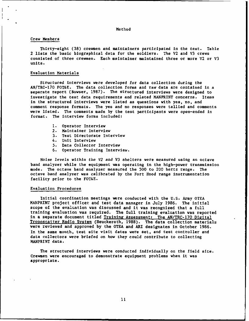
Thirty-eight (38) crewmen and maintainers participated in the test. Table2 lists the basic biographical data for the soldiers. The V2 and V3 crewsconsisted of three crewmen. Each maintainer maintained three or more V2 or V3units.
Evaluation Materials
Structured interviews were developed for data collection during theAN/TRC-170 FOT&E. The data collection forms and raw data are contained in aseparate report (Bowser, 1987). The structured interviews were designed toinvestigate the test data requirements and related MANPRINT concerns. Itemsin the structured interviews were listed as questions with yes, no, andcomment response formats. The yes and no responses were tallied and commentswere listed. The comments made by the test participants were open-ended informat. The interview forms included:
I. Operator Interview2. Maintainer Interview3. Test Directorate Interview4. Unit Interview5. Data Collector Interview6. Operator Training Interview.
Noise levels within the V2 and V3 shelters were measured using an octaveband analyzer while the equipment was operating in the high-power transmissionmode. The octave band analyzer measured the 500 to 200 hertz range. Theoctave band analyzer was calibrated by the Fort Hood range instrumentationfacility prior to the FOT&E.
Evaluation Procedures
Initial coordination meetings were conducted with the U.S. Army OTEAMANPRINT project officer and test data manager in July 1986. The initialscope of the evaluation was discussed and it was recognized that a fulltraining evaluation was required. The full training evaluation was reportedin a separate document titled Training Assessment: The AN/TRC-170 DigitalTroposcatter Radio System (Heuckeroth, 1988). The data collection materialswere reviewed and approved by the OTEA and ARI designates in October 1986.
In the same month, test site visit dates were set, and test controller anddata collectors were briefed on how they could contribute to collectingMANPRINT data.
The structured interviews were conducted individually on the field site.Crewmen were encouraged to demonstrate equipment problems when it wasappropriate.
11

Table 2
Crewmen and Maintainer Basic Demographics
Operators
N = 35
MOS: 26QD6
Grade: E5 - 4 E4 - 6 E3 - 25
Mean Age: 21.0
Mean Time in Military: 2.3 years
Mean Time in MOS: 1.4 years
Mean Civilian Education: 12.2 years
Mean Military Education: 7.0 months
Military Schools Attended (average): 2
Respondents Per System: V2 - 19 V3 - 11 Section Chiefs 5
Maintainers
N-3
MOS: 29M
Grade: E4 - 3
Mean Age: 27.6
Mean Time in Military: 3.8 years
Mean Time in MOS: 2.6 years
Mean Civilian Education: 12.6 years
Mean Military Education: 13.6 months
Military Schools Attended (average): 3
Respondents Per System: 3
12

Observations of AN/TRC-170 crews performing operations and tasks wereconducted throughout the test. Ten AN/TRC-170 terminals were deployed inpairs occupying five tactical sites during testing. The terminals were re-deployed every 96 hours, moving 104 times during day and night conditions.During Phase III of the test, networks were established simulating a corpsnodal network, a skip node network, and a corps network using the trafficloading device. No threat, electronic warfare, or nuclear, biological, andchemical (NBC) tactics were simulated during the test. Test OperationsProcedure 7-2-610 (November, 1983) was used to guide the on-site observations.Observations were used to identify unanticipated problems of AN/TRC-170operations and to extend the MANPRINT specialist's understanding of findingsfrom the analysis of structured interviews.
Instrumented measures of noise levels within the shelter were measuredwith the doors opened and closed. The octave band sensor was held at 36inches above the floor at approximately the ear height of a seated operator.
Task performance timed measures were collected for crewmen performing siteemplacement and disemplacement tasks. The purpose of the timed measures wasto examine the task time lines in comparison to the system emplacement anddisemplacement time criteria. Lengthy task performance times may suggesttasks requiring procedural modification, job aids, and tools. The AN/TRC-170is a microwave terminal, and as such, the majority of crew tasks involve set-up and tear-down tasks. Once the terminal is emplaced, crewmen monitorterminal functions and no complex operational tasks occur. Thus, the majorityof the crew responsibility is focused on the rapid and proper assembly anddisassembly of the equipment. Forty-two timed measures were collected by testdata collectors. Test data collectors were briefed on the data elementdefinitions (operational definitions) for each of the measures and thenobserved in the field to ensure that they understood the measure start andstop cues. Measures of task errors were not collected as prescribed operatingprocedures were being revised by the manufacturer. Thus, procedural taskerrors could not be distinguished from crew-implemented efficiencies.
The MANPRINT findings were compiled by the OTEA Human Factors Specialistinto a Scoring Conference Booklet. For each problem, the following informa-tion was provided: 1) problem number, 2) problem title, 3) MANPRINT category,4) tentative problem/correction priority, 5) information sources, 6) descrip-tion of problem, 7) implications, 8) statistics, 9) potential solutions.Manufacturer's (Raytheon) representatives attended to provide a source oftechnical information. Problem and correction criteria ratings were deter-mined by a majority of the voting participants, who were: 1) OTEA HumanFactors Specialist, 2) OTEA Operational Test Director, 3) TRADOC (TMS) repre-sentative, 4) CECOM Project Manager representative, and 5) TECOM representa-tive. The findings were reviewed individually and then scored by consensus atthe end of the test. The rating scales are listed in the results section ofthe report.
13
Results
Twenty-four MANPRINT findings were found regarding the equipment of theAN/TRC-170. Table 3 lists the performance impact and correction priorityrating scales used to score the MANPRINT findings. Table 4 lists a summarydescription of the 24 MANPRINT findings. Following the summary table aredetailed descriptions of the findings. Finally, a review of the timed taskperformance measures is presented.
Detailed Descriptions of Findings
Detailed descriptions of each of the 24 MANPRINT findings are presented onpages 18 through 56.
14

Table 3
Performance Impact Rating Scale and Correction Priority Scale
I. Performance Impact
A. The design deficiency has a significant =ac on human perfor-mance, leading to a high probability of mission failure, damageto the vehicles, or injury to personnel. Problem solutioncormidered essential for production model.
B. The design deficiency has a significant impa on human perfor-mance, leading to a high probability of degraded mission capaci-ty. Problem solution should be included in the productionmodel.
C. Th correction of the design deficiency will significantlyenhance the operability and/or maintainability of the system.
D. The design deficiency can be corrected by a hardware change orcan be compensated for through training.
E. The design deficiency has minmal impact on mission. Correctionwill enhance human performance.
II. Correction Priorities
1. Corrective action must be taken before a retest.
2. Corrective action must be incorporated before fielding.
3. Corrective action must be incorporated during fielding.
4. Corrective action would wbtantially improve performance andshould be taken.
5. Corrective action would have minor impact on operation andshould be taken if no significant cost is involved.
15
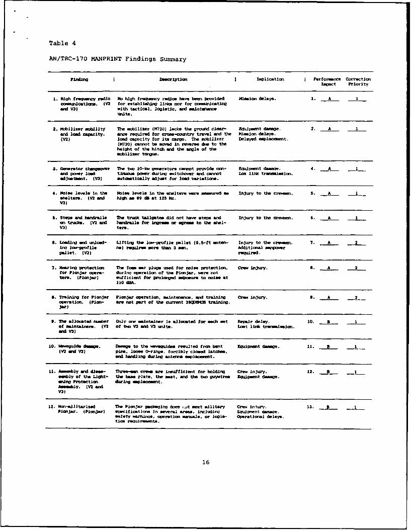
Table 4
A1N/TRC-17O MANPRINT Findings Summary
Finimi Description Implication Performance correctionlovet Priority
1. High frequency radio No high frequency rui~om have bees provided Mission delays. 1. A1comxinistione. (V2 for establishing links nor for ooceusactingAnd V31 with tactical, logistic, and ma~inteancex
unit*.
2. mobilizer mobIlity The mobilizer (K?20) lacks the ground clear- Equimet damage. 2. Aand 1la1 capacity. arcs required for cross-coutry travel and the Mission delays.(V2) loa capacity for Its cargo. The mobilizer Delayed emlaeet.
(M 720) cannot be moved in reverse due to theheight of the hitch aid the angle of themobilizer tongue.
3. Generator chongeow The two 1O-Iow genrators cannot provide am- Equipment damage. 4. A I_and powr Ice tirn~ power during awitchaver and cannot Los link trasisi.adjueit. MV) automatically adjut for lad variations.
4. Noise levels in the Noise levels in the stelters "m measured as Injury to the crewmen. 5. A1shelters. (V2 and high as 69 dB at 125 Nz.V3)
5. Stems and handrail@ The truck tailgates did not have st"r and Injury to the crewen. 6. A1an tr.w~cm. (V2 and hwralsl for ingress or egress to the ahel-VI) term.
6. Loadirg and unloa- Lifting the low-profile pallet (9.5-ft anten- Injury to the crsm 7. A 2Ing 1ow-profile na) requires mome then 3 sm. Aditional minpowerpallet. (V2) required.
7. Hearing protection The tam ear plugs timed f or noise protection. Crew injury. I. A 2for Pionjar opera- durirq operation of the Pionjar. were nottots. (Pin jar) suf f icent for prolong-ed aiur* to noise at
110 dBM.
B. Trairning for Pionjar Pionjar operation. ainteanice, and traininga Crew injury. 9. A 2opration. (Pion- are not part of the current 25(QlSIB training.jar)
9. Vie allocated raaber Only one mintainer is allocated for each set Rpaair delay. 10. 3 Iof maintainers. (V2 of two V2 and V3 writs. Lost link triinmmon.ard V3)
10. Novegaids dmg. Ease" to the i'mvauie resulted f rom bent Equipiat damage. 11. B 1(V2 mid V3) ping, loose 0-rings, forcibly closed latces
and handlingr during antenna emlacemnt.
11. Assembly and diess- Three-san cr..m are insufficienit for holding Crew Injury. 12. B -1sebly of the Light- the base plate. the seat, aid the two guysires Equimnt damage.uing Protection during mlaom t.Asmbly. (V2 andV3)
12. Non-dlitarized 7Ve Pionjar I I ix dos .t seet Kilitary Crew iury. 13. BPlonjar. (Pionjar) areclticatome In several aeas. including IqnUient damagoe.
safety earnings, opration manuas, or login- Operational delays.tIcs requlawesita.
16
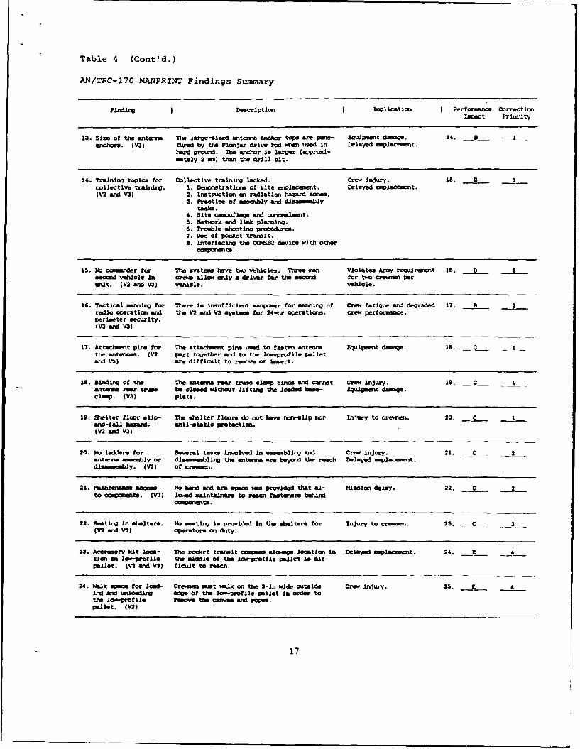
Table 4 (Cont'd.)
AN/TRC-170 MANPRINT Findings Summary
FindigI Decription Implicatio I Performe CrrectionImpact Priority
13. Size ot the antema The large-eilzed antemna anchor tops are Punc- Eg~upiment damage. 14. B 1anchore. MV3) tured by the Plnjar drive i, w:1 used In Delayed emplacemet.
hard ground. The anchor Is larger (apprcoi-ma"tely 2 mm) than the drill bit.
14. Trainim topics for Collective training lacYed: Crew injury. 15. B 1collective training. 1. Demonstratior ot site emplacemnt. Delayed wiplament.(V2 and V3) 2. Instruction an radiation hazard zes .
3. Practice of asmbly and dlasemblytask.
4. Site camoflag and ccealmt.5. Network " link plannrinq.6. Trouble-shootIn procedures.7. Use of packet trailt.8. Interfacing the C6SEO device with other
IS. No caamener tar The sytm haye two vehicles. Three-man Violates Army requiriant 16. 8 21ecd vehicle in cros allow only a driver tr the e for two crevviee per
unit. (V2 and V3) Vehcle. vehicle.
16. Tactical mennUn for There in insufticient manpwer for marning of Crew fatigue and degraded 17. B 2radio operation and the V2 and V3 myat for 24-hr operetions. crew performance.perimeter security.(V2 and V3)
17. Attacet pine tor Te attamt pirta med to fasten antenna Equitnt dame. Is. C Ithe antav. (V2 Pgrt together and to the lot-profle pelletand VJ) aft ditticult to remove or Ineert.
1d. Blrdin of the 'e antenna rea trus clerp birds and cannot Crew injury. 19. C 1antem rear trume be closed without lifting the loaded be- Equipment damage.clamp. (M13) plate.
19. Shelter tloor slip- The shelter floorm do not have ron-lip nor Injury to crewmn. 20. C 1and-tall hazard. anti-static protection.(V2 adV3)
20. No ladder for Several tass involved In aesembling and Crew injury. 21. C 2antema smembly or diuasambling the antema ae beyond the reach Delayed emplac ment.disassembly. (V2) of crewmen.
21. Maintenanc acs No d and arm I was provided that al- Mission delay. 22. C 2to anowntts. (V3) lowed mIntainer, to reach fteeners e nd
caspoents.
22. Seating in shelter*. No seating Is provided in the sheltere for Injury to creman. 23. C 3(V2 aid V3) operators an duty.
23. Acce soay kit acs- The packet trarult oma stoage location in Delayed plaoent. 24. _E 4tion an lao-profile the middle of the low-profile pallet ia dit-pallet. MV2 and V3) ticult to reach.
24. Walk epae for load- Crewaen must walk an the 3-in wide outaide Crew injury. 25. Z 4Ing and wloading e of the low-profile pellet In order tothe loo-profile av the ceiwam and ras.pIllet. ( 12)
17

Problem Title: High Frequency kadio Communications
System: V2 and V3
MANPRINT Category: Human Factors
Information Sources: On-site observations; operator, data collectors, andTest Directorate opinions; performance and RAM data.
Description of the Problem: The V2 and V3 systems do not include a highfrequency (HF) radio. The HF radio is critical to link logistics, engineeringand maintenance personnel of the deployed units. The HF radio communicationsfacilitate positioning of the unit and establishing a radio link before
microwave transmissions can be made.
Implications: Establishing microwave tropospheric links may be eitherdelayed or prevented without independent HF communications. Management ofthe maintenance activities at the levels required for testing may not be pos-sible.
Data: During the test, 90% of the Tropo links were established using RF orFM radio assistance. The maintenance system was fully dependent upon HF orFM radio communications.
Potential Solutions: A HF radio should be selected for the AN/TRC-170 and
supplied with all systems.
18
Problem Title: M-720 Mobilizer Mobility and Load Capacity
System: V2
MANPRINT Category: Safety
Information Sources: MIL-STD-1472C, paragraph 5.13.1; on-site observations;AR 750-10, Modification of Materials.
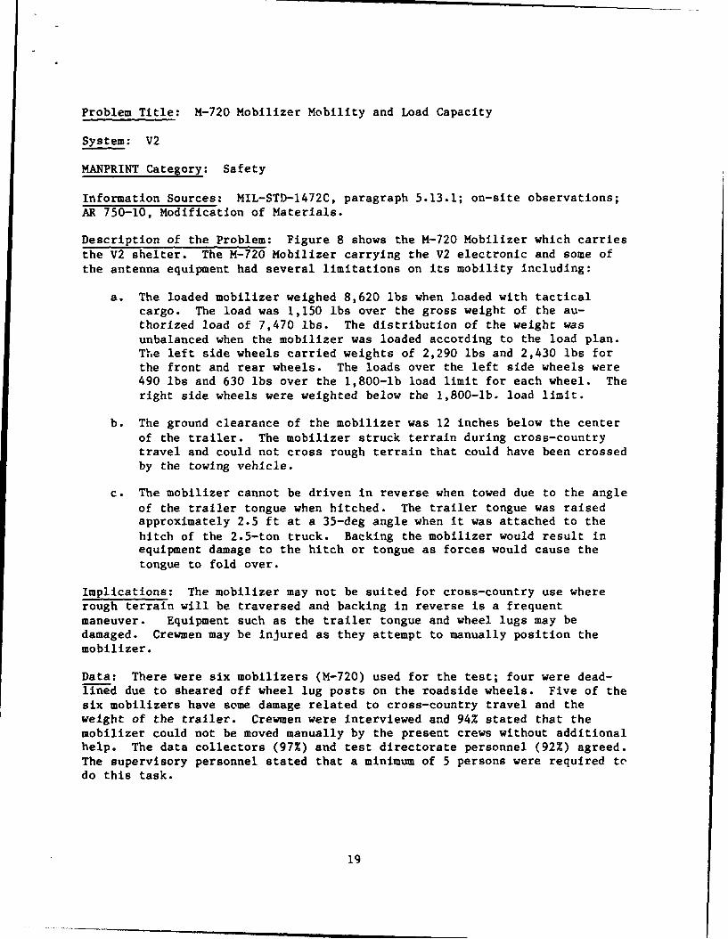
Description of the Problem: Figure 8 shows the M-720 Mobilizer which carriesthe V2 shelter. The M-720 Mobilizer carrying the V2 electronic and some ofthe antenna equipment had several limitations on its mobility including:
a. The loaded mobilizer weighed 8,620 lbs when loaded with tacticalcargo. The load was 1,150 lbs over the gross weight of the au-thorized load of 7,470 lbs. The distribution of the weight wasunbalanced when the mobilizer was loaded according to the load plan.The left side wheels carried weights of 2,290 lbs and 2,430 lbs forthe front and rear wheels. The loads over the left side wheels were490 lbs and 630 lbs over the 1,800-lb load limit for each wheel. Theright side wheels were weighted below the 1,800-lb. load limit.
b. The ground clearance of the mobilizer was 12 inches below the centerof the trailer. The mobilizer struck terrain during cross-countrytravel and could not cross rough terrain that could have been crossedby the towing vehicle.
c. The mobilizer cannot be driven in reverse when towed due to the angleof the trailer tongue when hitched. The trailer tongue was raisedapproximately 2.5 ft at a 35-deg angle when it was attached to thehitch of the 2.5-ton truck. Backing the mobilizer would result inequipment damage to the hitch or tongue as forces would cause thetongue to fold over.
Implications: The mobilizer may not be suited for cross-country use whererough terrain will be traversed and backing in reverse is a frequentmaneuver. Equipment such as the trailer tongue and wheel lugs may bedamaged. Crewmen may be injured as they attempt to manually position themobilizer.
Data: There were six mobilizers (M-720) used for the test; four were dead-lined due to sheared off wheel lug posts on the roadside wheels. Five of thesix mobilizers have some damage related to cross-country travel and theweight of the trailer. Crewmen were interviewed and 94% stated that the
mobilizer could not be moved manually by the present crews without additionalhelp. The data collectors (97%) and test directorate personnel (92%) agreed.
The supervisory personnel stated that a minimum of 5 persons were required todo this task.
19

Potential Solutions: The internal shelter configuration had all the elec-tronic components positioned on the roadside of the mobilizer. Perhaps theelectronic components could be repositioned on both sides of the mobilizer inorder to balance the load. However, the only way to avoid exceeding theweight capacity of the mobilizer may be to use a larger-capacity mobilizer.
20
The shelter was imbalancedand too much weight wasplaced on the roadside(left) wheels.
M-720
/2LTON (LP AN/TRC-170_72 1/2 TON MZ-3.I._L. V2
The angle of the hitch The mobilizer groundprevented backing of clearance was too lowthe truck and mobilizer, for cross-country terrain.
Figure 8. The M-720 mobilizer carrying the S-665 shr*ter. (The actualconfiguration of the mobilizer differed slightly from thegraphic representation.)
21

Problem Title: Generator Changeover and Power Load Adjustment
System: V3
MANPRINT Category: Human Factors
Information Sources: On-site observations and test participant comments.
Description of the Problem: There are two 10 kw generators mounted on asingle trailer used to support the operation of the V3 system. The genera-tors have two operational problems including:
a. The generators cannot be switched from one to the other withoutshutting down the V3 system. The generators need to be switched whenfuel is emptied or repairs are required. Once the V3 is shut down, aperiod of 10 to 15 minutes i required for system warm-up before radiotransmissions can be resumed.
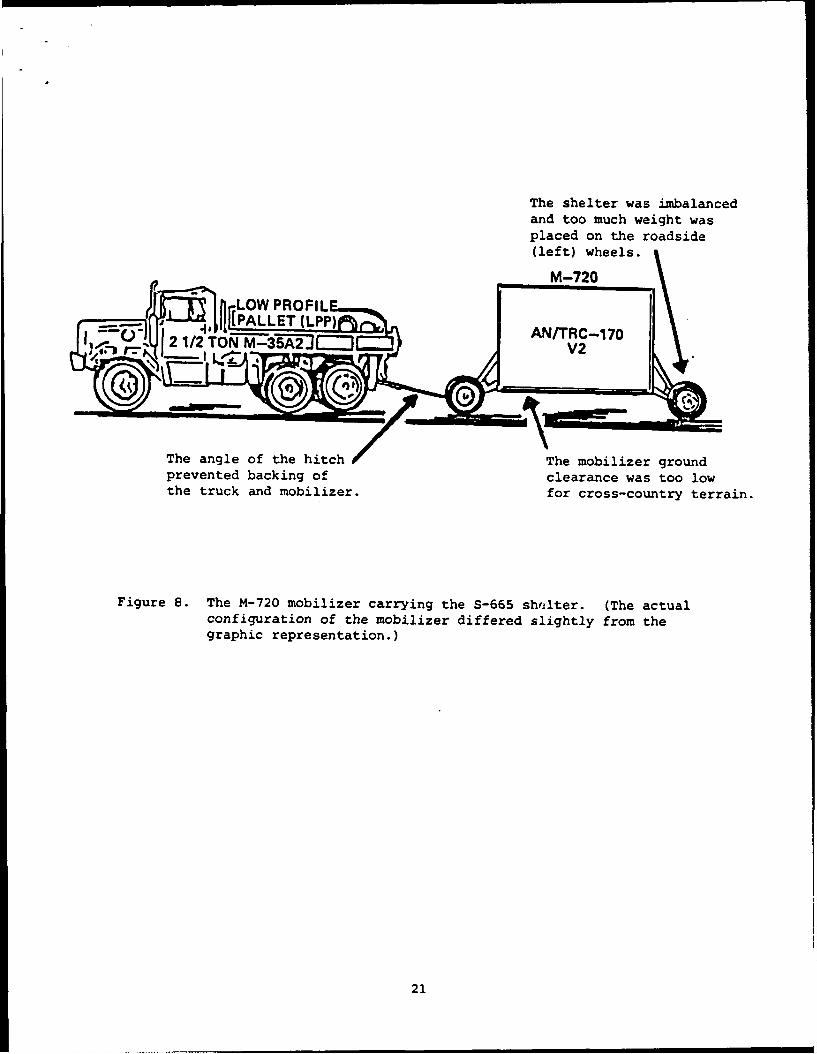
b. Figure 9 shows the V3 main power panel. The generators do not have abuilt-in capability to adjust for power load variations. When powerload variations occur, the operator must see the variation on thepower panel voltage meter in the V3 shelter or on the generator andthen adjust the generator. Power load variations occur when com-ponents in the V3 shelter are turned on or off.
Implications: Interruptions to the radio transmissions for generator switch-over occurred every 6 hrs. Unexpected shutdown for generator failuresresulted in lost transmissions. Failure to adjust the generators for powerload variations may result in a generator shutdown.
Data: The interruptions to the radio transmissions resulting from thegenerator shutdowns occurred throughout the test.
Potential Solutions: Provide the generators with switching capability thatprovides continuous power without power fluctuations. The generators shouldbe able to automatically adjust for load variations.
22
WTMRIO MAIN
U HPAO a M F off,
t7 i ,i
PRIME POWER 00 0INTERRLPT
CONSU.Iftilpto
OS0 The only indication the crewman0#4had of a power load variation
_ was in the shift of the voltageCPAS SELET((' meter needle.
LIHT INTLKII>jAMERS VEM VOLTS
ACC
LIu~~ a mall &Lee 0 Pol Pal~
000000000ON.
LWI UW SC1ICIU WAI JLI
a.i ow- Lt. I. Oe.i ow h O
(000000001
Figure 9. The main power panel in the V3 shelter.
23
Problem Title: Noise Levels in the Shelters
System: V2 and V3
MANPRINT Category: Safety
Information Sources: Measures of sound level taken by the MANPRINT spe-cialist; MIL-STD-1472C, paragraphs 5.8.3.1 - 5.8.3.4; MIL-STD-1474B NoiseLimits for Army Material.
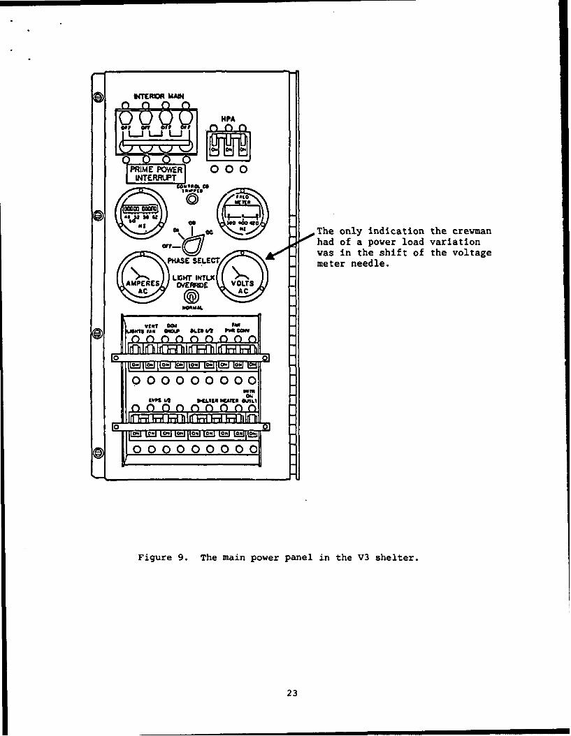
Description of the Problem: The noise levels within the S-280 and S-250shelters exceed the minimum ranges for hearing damage. Hearing protectionwas required during testing for all persons in the shelter during shelteroperation.
Implications: The operators and support personnel for the AN/TRC-170 systemmay suffer hearing loss unless hearing protection becomes a requirement forthe fielded V2 and V3 systems.
Data: Measures were taken with shelter door open and closed. The systemswere operating in high power mode.
Shelter Door Open Octive Band Frequency (Hertz)Weighted I 31.5 63 125 250 500 1K 2K 4K 8K 16K
V3 82 dB(A) 78 79 84 80 82 81 74 69 75 71V2 87 90 80 89 79 83 87 78 72 70 71
Shelter DoorClosed
V3 83 dB(A) 82 81 86 80 84 87 81 75 75 69V2 89 90 80 89 80 87 87 78 73 71 71
Potential Solutions: Hearing protection should be required for V2 and V3operators and maintainers working in the shelters when the system is fielded.Ideally, noise levels in the shelters should be reduced. Sound-absorbingacoustical materials might be placed on the shelter walls or in the vicinityof noise-producing equipment.
24

Problem Title: Steps and Handrails on Trucks
System: V2 and V3
MANPRINT Category: Safety
Information Sources: MIL-STD-1472C, paragraphs 5.7.7.3 & 5.12.7.2c; MIL-H-46855B, paragraph 3.2.2.3i; on-site observations.
Description of the Problem: The tailgate steps on the shelter trucks weremounted on the side of the tailgate and did not have handrails. The heightof the tailgates (approximately 5 ft) on the trucks requires that steps beemplaced and used. The location of the steps used did not meet MIL stan-dards. Steps should be directly in front of the doors (center of thetailgate) and must have a handrail. The proper steps for access should bepart of the fielded system.
Implications: The lack of handrails and side-mounted steps may lead toaccidents.
Data: All twenty trucks used in the test were not equipped with safe steps.
Potential Solutions: Appropriate steps and handrails should be provided withall AN/TRC-170 systems.
25

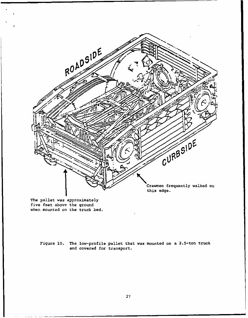
Problem Title: Loading and Unloading the Low-Profile Pallet
System: V2
MANPRINT Category: Manpower and Safety
Information Sources: Air Force crew size for the AN/TRC-170; the crew sizecalled for in the Technical Manuals; The 26QD6 operators opinions; on-siteobservations; Lifting and carrying standards from MIL-STD-1472C, paragraphs5.9.11.3.1 - 5.9.11.3.9.
Description of the Problem: Figure 10 shows the low-profile pallet and itscontents. The loading and unloading of the low-profile pallet for the V2system (9.5 ft) antenna is unsafe to perform by three crewmen (AN/TRC-170 V2crew size). The weights that must be lifted and carried exceed MIL-STD-
1472C maximums for three soldiers. The unit (Heavy Tropo Company) does nothave other personnel available (TO&E) to support the crews in the field to
assist in lifting material. The system can not be set up with a two-man crewmaking the system un-emplaceable if any crew member is injured or otherwiseunavailable. The units may set up in isolated locations and other personnelmay not be readily available.
Implications: The crews may suffer injuries such as back strain, musclestrain, contusions, abrasions, or broken bones. The AN/TRC-170(V2) may notbe able to complete its mission.
Data: Seventy percent (70%) of the operators reported that it was difficultfor three crewmen to lift equipment when loading and unloading the low-profilepallet.
Potential Solutions: The crew size could be increased by the addition of amaintainer (29M or 29S) to add to the number of persons available for loadingor unloading. The procedures for the truss assembly might be modified toreduce the weight lifted by crewmen when disassembling the truss on thepallet.
26
fit
I Crewmen frequently walked on
this edge.
The pallet was approximatelyfive feet above the groundwhen mounted on the truck bed.
Figure 10. The low-profile pallet that was mounted on a 2.5-ton truckand covered for transport.
27

Problem Title: Hearing Protection for Pionjar Operators
System: Pionjar
MANPRINT Category: Safety
Information Sources: MIL-STD-1472C, paragraph 5.8.3; on-site observations;MIL-STD-1474B, Noise Limits for Army Materials, paragraph C-7.
Description of the Problem: The measured noise level during operation of thePionjar was 110+ dB(A). The auditory noise produced by the Pionjar maydamage the operators' hearing unless they wear hearing protectors. ThePionjar also produces vibration and, in some cases, the vibration caused theoperator to lose ear plugs while operating the Pionjar. The standard earplugs may not be adequate protection for long-term exposure to the noise.
Implications: Operators may experience loss of hearing acuity and may suffercomplete loss of hearing in some frequency ranges.
Data: The noise level was 110+ dB(A) at the Pionjar during drilling. Thenoise level was 85 dB(A) from a circle 25 ft in diameter around the operatingPionjar.
Potential Solutions: The operators should be issued a better hearing protec-tion device such as ear muff style protectors.
28
Problem Title: Training for Pionjar Operation
System: Pionjar
MANPRINT Category: Training
Information Sources: AR 70-1, System Acquisition Policy and Procedures; MIL-STD-882B, System Safety Program Requirements; on-site observations.
Description of the Problem: The Pionjar operation, maintenance, and safetyprocedures are not part of the current Army training system for the 26QD6 MOS
crewmen. The Pionjar is a useful tool, but can be dangerous unless it is usedproperly. The lack of operation and maintenance training for operators mayjeopardize their safety and may reduce the useful life of the Pionjar.
Implications: Without proper training, more time may be needed to set
anchors. Without maintenance training, the Pionjar may have a shorter duty
life. The Pionjar operators may suffer injury.
Data: During the test, six Pionjars were disabled due to improper fuelmixtures. Three Pionjar drive rods were bent during the test. In two cases,
system set-up was delayed. Pionjar would not operate due to impropermaintenance.
Potential Solutions: Provide training for operators of the Pionjar. Thetraining could be handled at the unit level with TRADOC support. Su' " supportmight include preparation of a training video which addresses operation,maintenance and common system failures. Providing commercially preparedcanisters of premixed fuel would reduce training requirements and potentialproblems resulting from incorrect mixtures.
29

Problem Title: The Allocated Number of Maintainers
System: V2 and V3
MANPRINT Category: Manpower
Information Sources: On-site observations, maintainer and test directorcomments.
Description of the Problem: The number of maintainers allocated in the TO&Ewas one for every two V2 and V3 units. However, the units may be separated by100 miles or more. One maintainer was unable to provide service to two unitson a 24-hour operational schedule.
Implications: During combat, it may be impossible for one maintainer totravel the required distances and to be available for 24-hr periods.
Data: During testing, three maintainers per set of units were used.
Potential Solutions: The allocation of maintenance personnel (29M) for thissystem should be increased to one maintainer for each fielded system. The
maintainer could also be used as an additional operator and as crew toaugment set-up and tear-down tasking. The type of maintenance actions that
crewmen are allowed to perform might be increased.
30

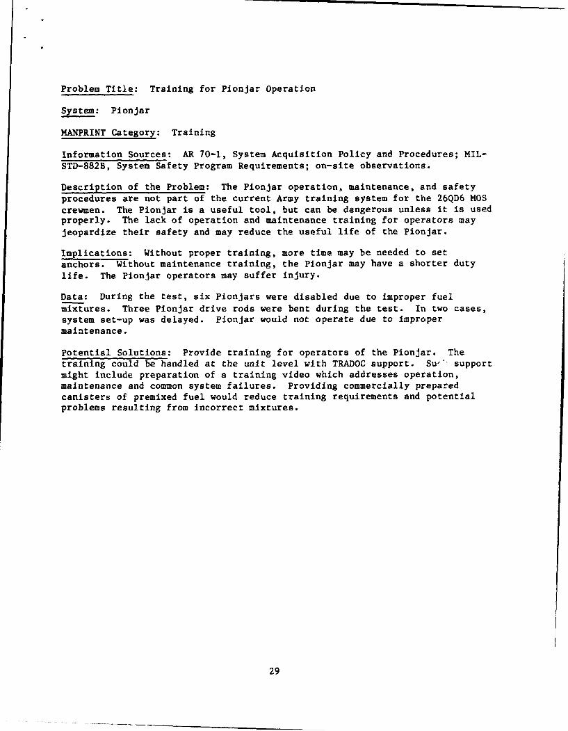
Problem Title: Waveguide Damage
System: V2 and V3
MANPRINT Category: Human Factors
Information Sources: On-site observations, operator comments, and RAM data.
Description of the Problem: The waveguides, linking the shelters to theantennas, were frequently damaged including:
a. The male plug alignment and signal pins bend, loosen, and fall out.
b. The male plug O-ring forming the moisture seal falls out makingalignment difficult and risking loss of the 0-ring. Figure 11 showsthe location of the 0-ring and latch device.
c. The latch securing the male plug to the female socket was difficult tomanipulate and had to be forcibly closed. The latch could not beclosed by crewmen wearing MOPP NBC gloves.
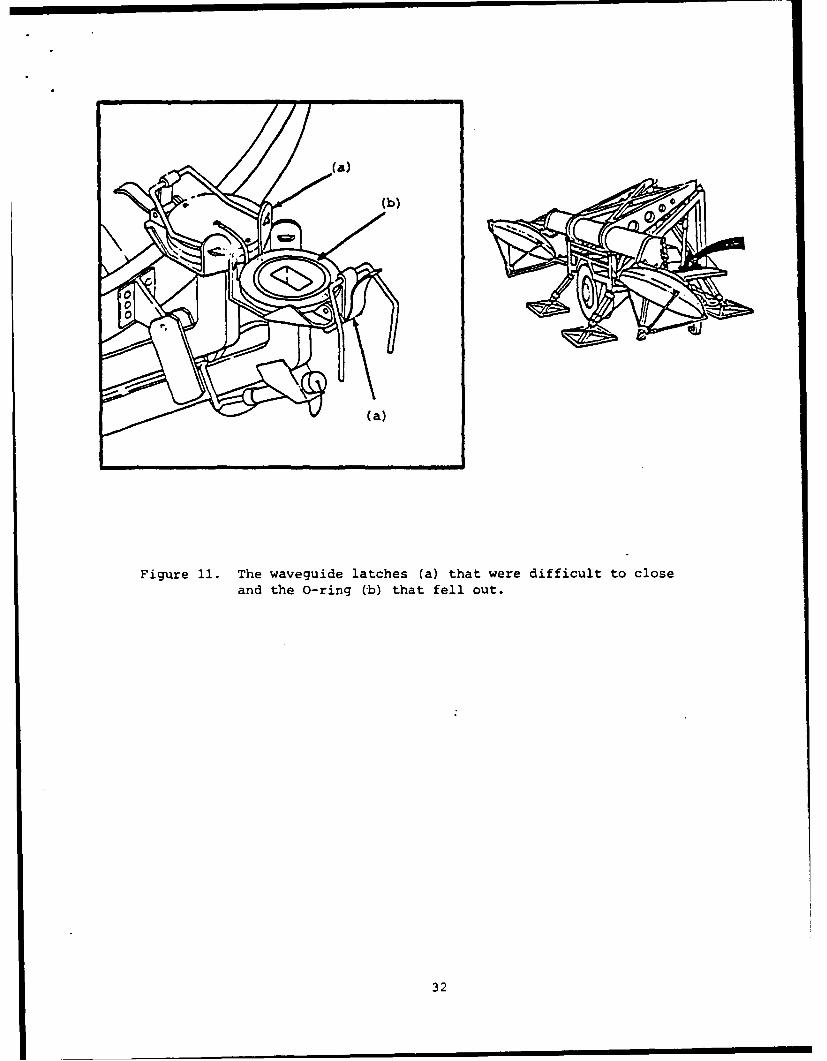
d. The protective transport containers for the waveguides used on the V2
system were attached to the pallet. The waveguides had to be carriedby crewmen from the pallet to the antenna. The exposed waveguideswere often stepped on or collided with objects. Figure 12 shows theprotective container, while Figure 13 shows the position of thewaveguides when laid out on the ground.
Implications: Several factors contributed to damaging of the waveguides.Damaged waveguides will prevent transmission. Additional replacementwaveguides will have to be supplied.
Data: Two-thirds (12) of the waveguides were damaged and unusable at mid-test.
Potential Solutions: The waveguides should be durable enough for the fieldenvironment in which they will be used. Operator training should address thesources and prevention of waveguide damage, especially if the design of thewaveguides remains unchanged. Two soldiers, rather than one, should be usedto support the waveguide when attaching or detaching it to the antenna inorder to keep it evenly supported.
31
(b)
Figure 11. The waveguide latches (a) that were difficult to closeand the O-ring (b) that fell out.
32
F. -T "-- 0
Figure 12. The waveguide protective contai.ner and trailer stowage location.
33

FLEXIBLEWAVEGUIDE DE-ICER
CABLE
~AZ/ELi SENSOR
SHELTER CABLEFLEXIBLE
DE-ICER WAVEGUIDESCABLE
Figure 13. The waveguides and other cables laid out on the groundprior to installation.
34

Problem Title: Assembly and Disassembly of the Lightning ProtectionAssembly (LPA)
System: V2 and V3
MANPRINT Category: Manpower and Safety
Information Sources: On-site observations; Opinions of the operators andtest directorate personnel; DA Pam 385-16, System Safety Management Guide.
Description of the Problem: Figure 14 shows the LPA configuration that iserected across the top of the antennas. The LPA erection procedures call forfour crewmen (crew size is three soldiers). The procedures require onecrewman to hold the base plate, one crewman to walk the mast up, and twocrewmen to hold the guywires controlling the mast as it rises. The currentequipment assembly procedures and the few personnel performing the task maylead to a situation resulting in the collapse of the mast.
Implications: The LPA is erected next to the AN/TRC-170 antennas and shelter.
The collapse of the mast might damage the antennas or shelter. The personnelare also endangered by a collapsing LPA mast.
Data: All the test participants (operators, supervisors, data collectors,and test directorate) recommended four-person crews for LPA erection/loweringtasks. Human Factors personnel observed 10 uncontrolled falls of the masts.In one case, an operator had the mast fall onto his shoulder causing a painfulinjury.
Potential Solutions: If the current LPA masts continue to be used, using ahinged base plate would make erection easier and safer, but for safety wouldrequire four man crews for erection. Alternately, consideration should begiven to use of telescopic antenna mast sections which are already in thesupply system. The training program should demonstrate correct erection/dis-assembly procedures to all 26QD6 personnel during specialty training.
35
ELECTRICAL WilE (SKYWIRE)
MAST SECIIONNO. IPN 97 70 79
MAST SECTIONNO. 2R4J977078
CENTER MAST HOOKS
CLAMP
MAST SECTIONNO. 2PH 9770
IEI DOWN ASSY(OUT WilEi
MAST ECTIO .0-SLIP PIN
OROUPID ROD AST &ASI GROUND ANCMH10
MAST NO. I MAST NQ.2
Figure 14. The lightning protection assembly (LPA) that was erectedacross the top of the antenna structures.
36

Problem Title: Non-Militarized Pionjar
System: Pionjar
MANPRINT Category: Safety
Information Sources: MIL-STD-1472C, paragraphs 4.9 and 4.10; On-siteobservations; TECOM TOP 10-2-508, Safety and Health Hazard Evaluation -
General Equipment.
Description of the Problem: Figure 15 shows a cut-away view of the Pionjardrive motor. Problems found on the non-militarized Pionjar included:
a. The Pionjars were not labeled with safety warnings.
b. Warning labels later supplied to the units did not remain affixed tothe Pionjars.
c. The Pionjar's operation and maintenance manual was not written tomilitary specification and did not contain the appropriate warnings orcautions.
d. The Pionjars supplied with the system (AN/TRC-170) were not packagedto military specification.
e. The equipment requires a mixture of gasoline and two cycle enginemotor oil for fuel which is not a regularly supplied field item.
Implications: The lack of warnings and cautions may lead to accidents. ThePionjar is currently required to set up the antenna system in support of theAN/TRC-170. The durability and supply characteristics of the Pionjar shouldbe assessed.
Data: Six Pionjars were unavailable due to maintenance problems during thetest. The supply system issued improper oil for the oil and gas mixture thatis required, causing some Pionjar failures. The crews in some distant siteshad to obtain regular gasoline and 2-cycle motor oil from retail stores in
order to operate the Pionjar.
Potential Solutions: A separate test of the Pionjar is needed. The device
should also be required to meet military packaging and labeling standards.The logistics issue need review.
37

Figure 15. A cut-away view of the Pionjar drive motor and of the duckbill anchor.
38

Problem Title: Size of the Antenna Anchors
System: V3
MANPRINT Category: Human Factors
Information Sources: On-site observations; Opinions and observations ofoperators and test directorate personnel. Results of Air Force system testsin 1980.
Description of the Problem: The diameter of the duckbill portion of theanchor is larger than the pilot hole drilled by the Pionjar with the drillbit. The anchor is designed to hold in soft ground, but it is difficult touse in hard or rocky ground. The anchor is not shaped to be driven using thePionjar and the drive rod often punches through the anchor becoming stuck.
Implications: The use of the anchors is limited and difficult unless theyare restricted for use in geographic areas with soft ground. The timerequired for setting anchors is increased when the anchors become stuck.
Data: The setting of anchors has taken as long as 19 hrs for 12 anchors.All crewmen agree that a more suitable anchor is required to make the systemtactically usable. Sixty-three percent (63%) of the operators and field datacollectors reported that in a tactical situation, the present anchors shouldnot be used. Four driving rods have been bent and the manhours required toremove them have exceeded 8 hrs per incident.
Potential Solutions: The present anchors could be used in addition to anassortment of sizes to be used depending on soil conditions. The systemdeveloper should review the anchors already on the market and find a moreusable anchor or set of anchor sizes than the one selected. A less spe-cialized anchor design might reduce the cost of the anchors.
39
Problem Title: Training Topics for Collective Training
System: V2 and V3
MANPRINT Category: Training
Information Sources: On-site observations; training evaluations.
Description of the Problem: The collective training provided at Keesler AFBlacked several topics or techniques including:
a. Demonstrations of site emplacement and the locations of equipment forsafety and tactical security.
b. Instruction and examples of radiation hazard zones for microwave
antennas.
c. Practice of equipment assembly and disassembly.
d. Site camouflage and concealment.
e. Network and link planning for staff and operations personnel.
f. Detailed troubleshooting for system operating difficulties and for
fault isolation.
g. Use of the pocket transit for crewmen.
h. Interfacing the COMSEC device and its operating procedures with theother electronic components. The lockup of the COMSEC orderwirebridge resulted from operators not realizing that the VINCINT devicewas not in the appropriate status.
Implications: Without the appropriate training, crewmen may emplace the unitcreating safety problems such as: personnel walking through microwave hazardzones, placing the stowed fuel too close to the generators, and placing thegenerators too close to the sleeping areas. The tactical security of the unit
could be compromised by improperly concealed equipment, blocked views of enemyapproach routes, and blocked evacuation routes. Delays during emplacement may
result from difficulties in establishing network links or from time spenttroubleshooting difficulties.
Data: Seventy-one percent (71%) of the operators reported that additionalcollective training was needed.
Potential Solutions: The AN/TRC-170 system involves many emplacement,
assembly, and disassembly procedures. The procedures would be best taughtthrough field demonstrations rather than by instruction alone. Trainingmight be facilitated using video or slide tape instruction materials.
40
Problem Title: No Commander for Second Vehicle in Unit
System: V2 and V3
MANPRINT Category: Manpower
Information Sources: Army regulation and Unit standard operating procedures.
Description of the Problem: The present crew size is three crewmen persystem unit. Each system has two vehicles assigned as primary movers. Armyregulation and highway safety standards call for two crewmen (driver &assistant driver) for trips of longer than 10 hrs. The unit standardoperating procedures require a second person (assistant driver) when thevehicle is towing to act as a ground guide (both vehicles in V2 & V3 are usedto tow equipment).
Implications: The peacetime employment of the system will require thatadditional personnel be supplied by the unit during road march and fieldexercises. If not corrected, the situation in wartime may be overlooked.Potential loss of the system, due to driver fatigue or accidents related to
single driver operation, may result. The crew size places the unit in theposition of violating safety rules or not getting the system to the field in atimely manner.
Potential Solutions: The crew size for both systems should be increased tofour crewmen, two per vehicle. The fourth crewman does not necessarily haveto be from the 26Q MOS. It is recommended that an additional maintainer, suchas a 29M or a 29S, be added to each crew solving both the manpower and
maintenance allocation problems.
41
Problem Title: Tactical Manning for Radio Operation and Perimeter Security
System: V2 and V3
MANPRINT Category: Manpower
Information Sources: The opinions of unit supervisory personnel, AN/TRC-170crews; Test Directorate personnel; on-site observations; Field tacticaldoctrines.
Description of the Problem: The employment of the AN/TRC-170 systems isgoing to include situations where one or two systems are emplaced and isolatedphysically from all other military units. Tactically, the crews must man theradio with at least one person, man a Command Post radio, and providesite/perimeter security 24 hrs a day. There are not enough personnel assignedto the system to accomplish these requirements. If there are two systems, thecrew size requirement is for seven crewmen (three in each crew and a super-visor); and if only one unit, the crew size is to be three or four personsdepending on the location of the supervisory NCO.
Implications: The crew may suffer fatigue trying to meet all the require-ments of a tactical situation operating on a 24-hr basis.
Data: Of the 26QD6 operators interviewed, 83% stated the V2 crew was notlarge enough in tactical circumstances, and 74% agreed that the V3 crewrequirements for the tactical situation was not large enough. The super-visory and planning personnel all (100%) agreed crew size should be increasedto meet unit tactical demands. The test directorate were interviewed, and 83%also reported a need for increased crew size. The data collectors wereinterviewed, and 63% stated that tactical crew should be increased to meetmanning requirements.
Potential Solutions: Further study is needed to resolve the issue of crewsize. While in theory it could be assumed that site security could beprovided by collocated infantry units, such units are not always collocated.The unit TO&E should be increased to provide additional personnel to performthese non-system related tasks. The additional personnel do not have to be26Q MOS personnel. It is recommended that additional maintenance (29M or 29S)be considered as additions to meet any further validated manpower needs.
42
ELEVATIONCLEVIS PIN ACTUATOR
BOTTOMHUBCLEVIS
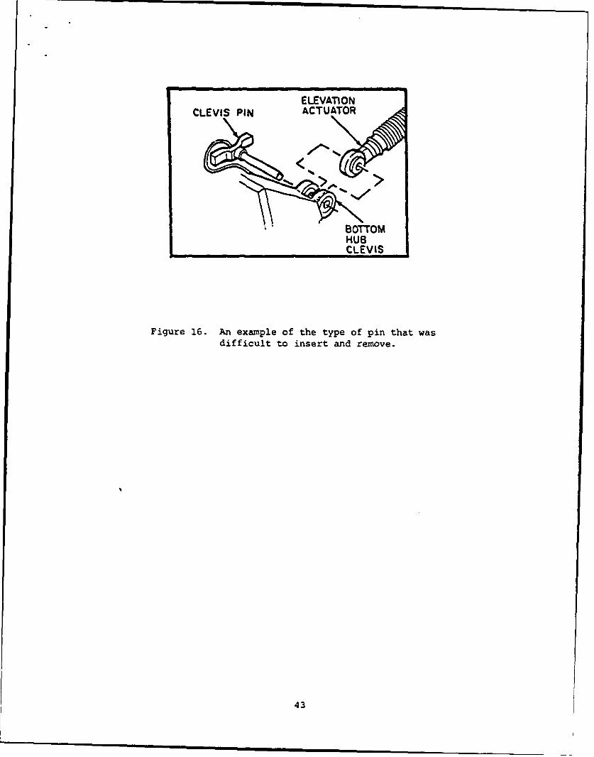
Figure 16. An example of the type of pin that wasdifficult to insert and remove.
43
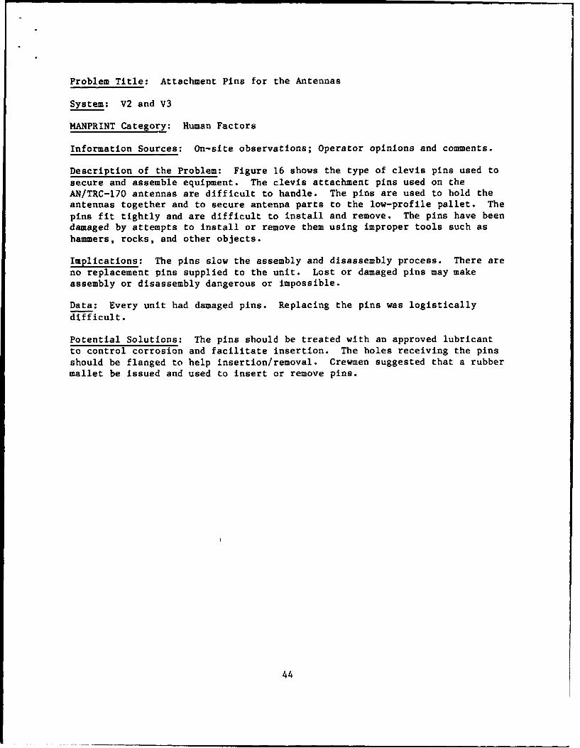
Problem Title: Attachment Pins for the Antennas
System: V2 and V3
MANPRINT Category: Human Factors
Information Sources: On-site observations; Operator opinions and comments.
Description of the Problem: Figure 16 shows the type of clevis pins used to
secure and assemble equipment. The clevis attachment pins used on theAN/TRC-170 antennas are difficult to handle. The pins are used to hold theantennas together and to secure antenna parts to the low-profile pallet. The
pins fit tightly and are difficult to install and remove. The pins have beendamaged by attempts to install or remove them using improper tools such ashammers, rocks, and other objects.
Implications: The pins slow the assembly and disassembly process. There areno replacement pins supplied to the unit. Lost or damaged pins may makeassembly or disassembly dangerous or impossible.
Data: Every unit had damaged pins. Replacing the pins was logisticallydifficult.
Potential Solutions: The pins should be treated with an approved lubricantto control corrosion and facilitate insertion. The holes receiving the pinsshould be flanged to help insertion/removal. Crewmen suggested that a rubbermallet be issued and used to insert or remove pins.
44

Problem Title: Binding of the Antenna Rear Truss Clamp
System: V3
MANPRINT Category: Human Factors
Information Sources: On-site observations; Operator comments.
Description of the Problem: Figure 17 shows the rear truss clamp and bearingball configuration. The rear truss clamp which locks down the bearing ball on
the end of the truss assembly binds. The clamp cannot be closed withoutlifting the loaded base place, a job that is heavy and dangerous. The problemoccurs when the antenna is set to the 15-ft height versus the 10-ft height.
Implications: The operators may be injured an/or the antenna damaged. The
rear truss might slip out of the base plate and fall. The antenna wouldbecome inoperable due to damage.
Data: The problem has been observed on 5 of the 12 antenna systems in test.
Theproblem was not corrected on all the fielded antennas by the end of thetest.
Potential Solutions: The rear clamp assembly needs to be modified. The new
antennas in production should be modified prior to fielding.
45

TRUSS SI LMBEARING BALL
(c)
The rear truss base pl~ate (a) mustbe lifted in order to seat thebearing ball (c) and close theclamp (b).
Figure 17. The 9.5-ft anten.~a (a), rear truss clamp ()and bearing ball (c).
46
Problem Title: Shelter Floor Slip-and-Fall Hazard
System: V2 and V3
MANPRINT Category: Safety
Information Sources: On-site observations; MIL-STD-1472C, paragraph 4.8; AR385-10 Army Safety Program.
Description of the Problem: The S-280 and S-250 shelter floors do not have
non-slip or anti-static surfaces. The shelter floors are painted metal andare dangerous unless surfaced with non-skid material. The electroniccomponents in the shelters are subject to damage by static discharge. Thefloor protection also needs to include an anti-static surface to preventdamage to electronic components from static discharge.
Implications: Crewmen may be injured in slip-and-fall accidents. Damage toequipment may be caused by falling crewmen striking equipment and by staticdischarge affecting the electronics.
Data: Twenty percent (20%) of the crewmen reported slipping on the shelterfloor when the floor or their boots were wet.
Potential Solutions: The shelters should be equipped with non-skid, anti-static floors or protective rubber mats.
47
Problem Title: No Ladders for Antenna Assembly and Disassembly
System: V2
MANPRINT Category: Safety
Information Sources: The system PLL; on-site observations; comments ofoperators and test directorate personnel.
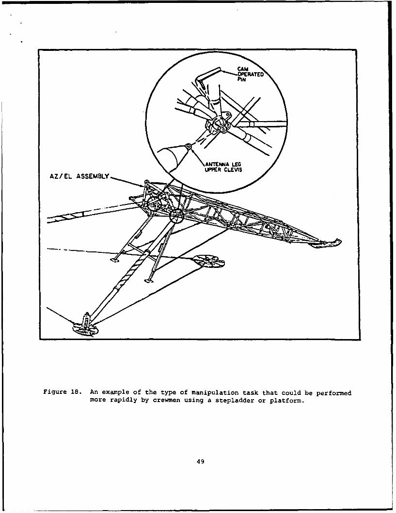
Description of the Problem: Figure 18 shows the type of manipulation taskthat must be performed on the 9.5-ft antenna. Figure 19 shows the antennahand crank that is difficult to reach. The assembly of the 9.5-ft antennahas several situations where personnel need to extend their reach. There isno ladder or other approved stand available on the AN/TRC-170. The situationsinclude the following:
a. Pins for the upper pedal assembly
b. Support struts for the Az/EL assembly
c. Roll yoke adjustment
d. Messenger cable installation and removal
e. Adjustment of waveguide connections
f. Loading/unloading the low-profile pallet.
Implications: The use of field-expedient methods used by crews may involvethe use of unstable and dangerous platforms. The antenna structure was notdesigned for climbing or standing on the cross braces. Equipment damage mayresult from climbing up the truss assembly.
Data: Sixty-three percent (63%) of the operators reported observing per-so nnel climbing or reaching in a dangerous manner. One operator broke hisfinger in the process of releasing the support struts for the AZ-EL assembly.Numerous reports were received concerning the dropping of antenna parts while
crewmen were reaching and climbing.
Potential Solutions: Provide a stand as standard equipment issue for the
AN/TRC-170(V2). It is recommended that at least a 3-ft high stand or ladderbe supplied.
48
PIN
ANTENNA LEGUPPER CLEVIS
AZ/EL ASSEMBLY
Figure 18. An example of the type of manipulation task that could be performed
more rapidly by crewmen using a stepladder or platform.
49

Crewmen frequentlyclimbed the bracestruts to makeadjustments.
HAND CANK
Figure 19. The 9.5-ft. antenna and hand crank that was difficult to use to reach theelevation angle adjustment device.
5o

?roblem Title: Maintenance Access to Components
System: V3
MANPRINT Category: Human Factors
Information Sources: MIL-STD-1472C, paragraphs 5.9.3 - 5.9.4; on-site
observations; maintainer comments.
Description of the Problem: Maintainers reported that they could not reach
component fasteners due to the limited space behind equipment panels. The
fasteners required excessive force before they would release from their
sockets. Due to the narrow walk space within the shelter, only one main-
tainer could access components weighing enough to require lifting by two
maintainers.
Implications: Performing maintenance is difficult due to space restrictions.
Rapid removal and replacement of components may not be possible.
Data: Eighty-three percent (83%) of the operators stated the work and main-
tenance area in the V3 was too small.
Potential Solutions: The space arrangements of components within the V3
shelter should be reviewed.
*5I
51

Problem Title: Seating in Shelters
System: V2 and V3
MANPRINT Category: Safety
Information Sources: On-site observations.
Description of the Problem: No seating was provided in the shelter for theoperator. The operator sits during extended time periods in the shelters.Operators used whatever objects were available (i.e., water coolers, Pionjarbox, folding chairs, etc.).
Implications: The operators will use what is available if seating is notprovided. This increases the potential for accidents causing injury tooperators and damage to equipment. The potential for crew back strain orfatigue is also increased without proper seating.
Data: Since seating was unavailable, all operators in the test used make-shiTt seating.
Potential Solutions: A fold-down or fixed, padded seat with a back restshould be provided in all shelters.
52

Problem Title: Accessory Kit Location on Low-Profile Pallet
System: V2 and V3
MANPRINT Category: Human Factors
Information Sources: AN/TRC-170 TM for the V2 system; on-site observations;Operator comments.
Description of the Problem: Figure 20 shows the location of the accessorykit on the low-profile pallet. The location of the accessory kit, whichincludes the pocket transit on the low-profile pallet, is located on thebottom of the pallet beneath the antenna truss structures. The pockettransit is the first item needed for site layout. The crew must remove thecanvas cover from the pallet and push antenna parts out of the way to retrievethe kit.
Implications: The emplacement of the antenna is delayed by the time requiredto obtain the pocket transit. Crew members must assume awkward and precariouspositions to get to the accessory kit. Crew injury is possible. The crew maychoose to not use the compass and this may lead to alignment errors.
Data: Fifty-one percent (51%) of all the operators recommended that thelocation of the accessory kit be changed. Seventy-five percent (75%) of thecrews moved the kit to either the truck cab or the shelter by the midpoint ofthe test without the direction of senior test participants.
Potential Solutions: The accessory kit should be placed in the shelter nearthe door or in the truck cab area for easy access.
53

Other equipment is stowed
above and around the
accessory alignment kit.
54

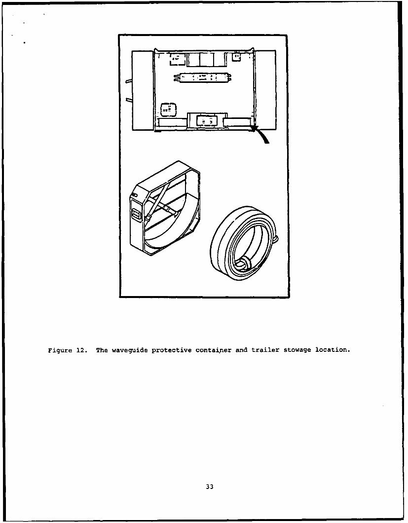
Problem Title: Walk Space for Loading and Unloading the Low-Profile Pallet
System: V2
MANPRINT Category: Safety
Information Sources: MIL-STD-1472C, paragraphs 4.4g and 4.8; on-siteobservations; AR 385-16, System Safety Engineering and Management.
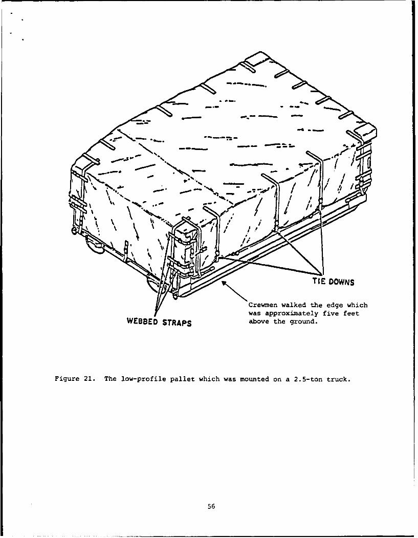
Description of the Problem: Figure 21 shows the low-profile pallet securedfor transport. Crewmen must walk on the outside edge (3-in width) of thelow-profile pallet in order to remove the canvas and ropes. Crew membersmust assume unsafe positions when removing the canvas cover and retrievingthe accessory kit.
Implications: The crews will be subject to slip-and-fall accidents.
Data: Seventy percent (70%) of the crewmen reported that it was difficultfor three crewmen to load and unload the low-profile pallet.
Potential Solutions: The canvas cover over the low-profile pallet could beprovided with a drawstring arrangement so that personnel would not have toclimb the side of the truck. The load on the low-profile pallet should beredistributed to facilitate loading and unloading, and consideration should begiven to moving some of the load to the shelter.
55
a.-.
, . -- / /,,
~Crewmen walked the edge whichwas approximately five feet
WEBBED STRAPS above the ground.
Figure 21. The low-profile pallet which was mounted on a 2.5-ton truck.
56
Task Performance Measures
System performance criteria for the AN/TRC-170 V2 and V3 systems included:
I. V2 system emplacement (set-up) time was not to exceed 240 minutes fora combination of all tasks, except LPA erection and anchors.
2. V2 system displacement (tear-down) time was not to exceed 120 minutes.
3. V3 system emplacement (set-up) time was not to exceed 120 minutes.
4. V3 system displacement (tear-down) time was not specified, but wouldbe specified on future tests based on the FOT&E results.
Crew task performance times are shown in the following series of tables.Table 5 lists the V2 system task set-up times for each of the tasks performed.The table also shows the tasks performed by 3- and 4-man crews. Table 6 liststhe V2 system tasks tear-down times for each of the tasks performed by 3- and4-man crews. Table 7 lists the V3 system task set-up times for each of thetasks performed by 3- and 4-man crews. Table 8 lists the V3 system task tear-down times performed by 3- and 4-man crews. The tasks performance times werecollected on a sample of occurrences that could be attended by the MANPRINTspecialist. The data was collected during Phase III of the test, after crewshad the experience of performing the tasks during pilot test and Phase IIrecord testing. The number of observations for each task are shown in the
tables. Several tasks were not performed by 4-man crews.
57
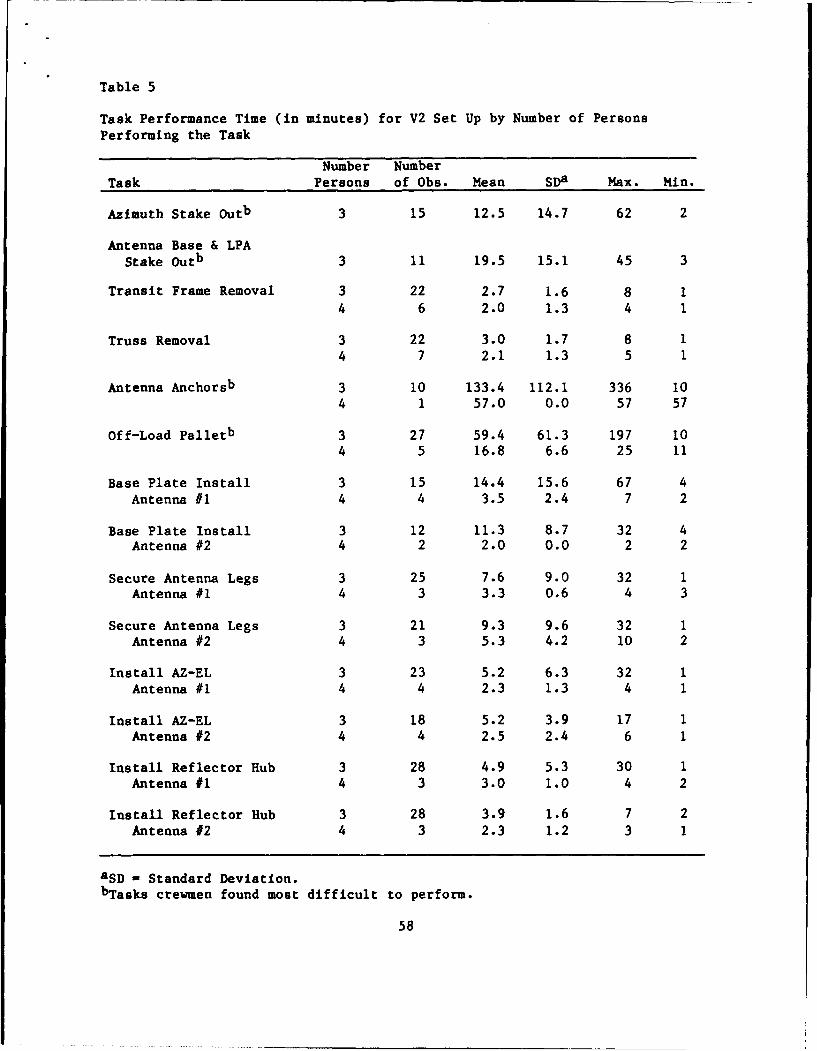
Table 5
Task Performance Time (in minutes) for V2 Set Up by Number of Persons
Performing the Task
Number Number
Task Persons of Obs. Mean SDa Max. Min.
Azimuth Stake Outb 3 15 12.5 14.7 62 2
Antenna Base & LPAStake Outb 3 11 19.5 15.1 45 3
Transit Frame Removal 3 22 2.7 1.6 8 14 6 2.0 1.3 4 1
Truss Removal 3 22 3.0 1.7 8 14 7 2.1 1.3 5 1
Antenna Anchorsb 3 10 133.4 112.1 336 10
4 1 57.0 0.0 57 57
Off-Load Palletb 3 27 59.4 61.3 197 104 5 16.8 6.6 25 11
Base Plate Install 3 15 14.4 15.6 67 4Antenna #1 4 4 3.5 2.4 7 2
Base Plate Install 3 12 11.3 8.7 32 4Antenna #2 4 2 2.0 0.0 2 2
Secure Antenna Legs 3 25 7.6 9.0 32 1Antenna #1 4 3 3.3 0.6 4 3
Secure Antenna Legs 3 21 9.3 9.6 32 1Antenna #2 4 3 5.3 4.2 10 2
Install AZ-EL 3 23 5.2 6.3 32 1
Antenna #1 4 4 2.3 1.3 4 1
Install AZ-EL 3 18 5.2 3.9 17 1Antenna #2 4 4 2.5 2.4 6 1
Install Reflector Rub 3 28 4.9 5.3 30 1Antenna #1 4 3 3.0 1.0 4 2
Install Reflector Hub 3 28 3.9 1.6 7 2Antenna #2 4 3 2.3 1.2 3 1
aSD - Standard Deviation.
bTasks crewmen found most difficult to perform.
58

Table 5 (Cont'd.)
Task Performance Time (in minutes) for V2 Set Up by Number of PersonsPerforming the Task
Number NumberTask Persons of Obs. Mean SDa Max. Min.
Install Upper Pedals 3 24 6.6 6.9 29 1Antenna #1 4 2 5.5 3.5 8 3
Install Upper Pedals 3 28 4.4 3.0 13 1Antenna #2 4 2 12.5 13.4 22 3
Install Roll Yoke Struts 3 16 4.8 3.4 15 1Antenna #1 4 2 4.0 1.4 5 3
Install Roll Yoke Struts 3 17 5.0 3.0 11 1
Antenna #2 4 1 1.0 0.0 1 1
Attach Waveguides 3 13 6.7 3.6 15 2Antenna #1 4 1 7.0 0.0 7 7
Attach Waveguides 3 14 6.9 3.1 12 2
Antenna #2
Antenna #1 Erection 3 28 14.7 9.7 54 3
4 1 21.0 0.0 21 21
Antenna #2 Erection 3 24 ±1.8 7.7 34 4
4 1 7.0 0.0 7 7
LPA Erectionc 3 18 60.7 48.3 183 194 22 44.2 32.2 126 13
Shelter Externalb 3 13 71.8 96.4 270 34 7 12.3 8.4 29 4
Shelter Internalb 3 8 38.1 40.1 125 8
Klystron Adjustmentb 3 3 31.0 25.7 51 2
Antenna Alignmentb 3 5 65.2 46.4 115 12
a SD - Standard Deviation.b Tasks crewmen found most difficult to perform.c LPA erection was not included in the system emplacement criteria.
59
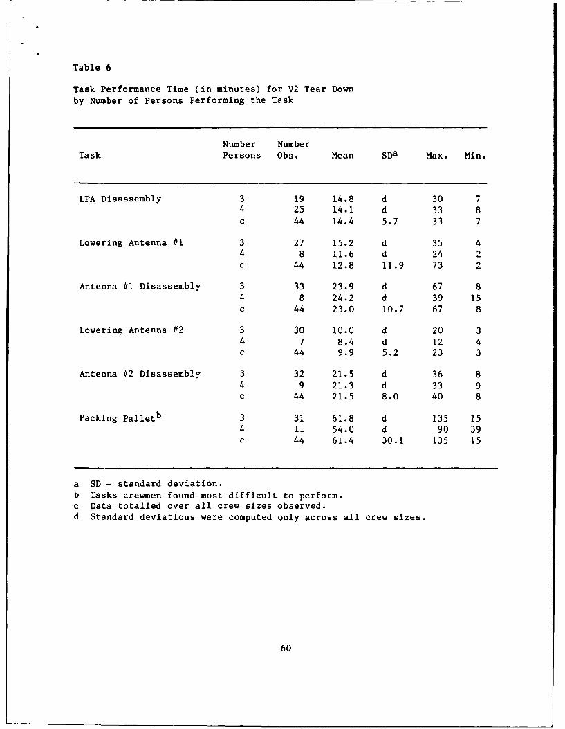
Table 6
Task Performance Time (in minutes) for V2 Tear Downby Number of Persons Performing the Task
Number NumberTask Persons Obs. Mean SDa Max. Min.
LPA Disassembly 3 19 14.8 d 30 74 25 14.1 d 33 8c 44 14.4 5.7 33 7
Lowering Antenna #1 3 27 15.2 d 35 44 8 11.6 d 24 2c 44 12.8 11.9 73 2
Antenna #1 Disassembly 3 33 23.9 d 67 84 8 24.2 d 39 15c 44 23.0 10.7 67 8
Lowering Antenna #2 3 30 10.0 d 20 34 7 8.4 d 12 4c 44 9.9 5.2 23 3
Antenna #2 Disassembly 3 32 21.5 d 36 84 9 21.3 d 33 9c 44 21.5 8.0 40 8
Packing Palletb 3 31 61.8 d 135 154 11 54.0 d 90 39c 44 61.4 30.1 135 15
a SD = standard deviation.b Tasks crewmen found most difficult to perform.
c Data totalled over all crew sizes observed.d Standard deviations were computed only across all crew sizes.
60
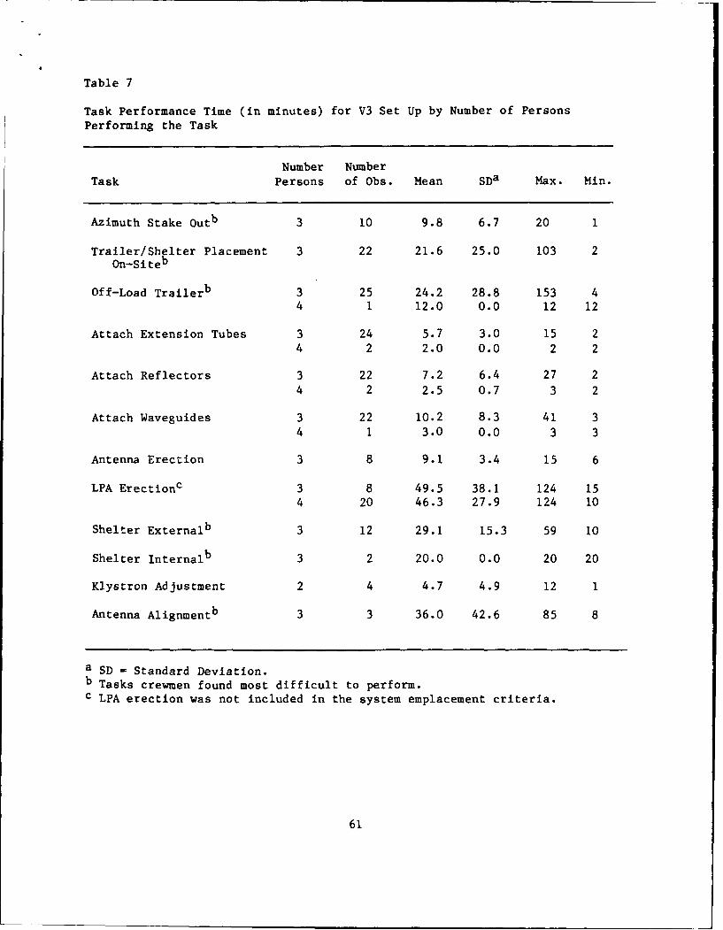
Table 7
Task Performance Time (in minutes) for V3 Set Up by Number of PersonsPerforming the Task
Number NumberTask Persons of Obs. Mean SDa Max. Min.
Azimuth Stake Outb 3 10 9.8 6.7 20 1
Trailer/Shelter Placement 3 22 21.6 25.0 103 2On-Site
b
Off-Load Trailerb 3 25 24.2 28.8 153 44 1 12.0 0.0 12 12
Attach Extension Tubes 3 24 5.7 3.0 15 24 2 2.0 0.0 2 2
Attach Reflectors 3 22 7.2 6.4 27 24 2 2.5 0.7 3 2
Attach Waveguides 3 22 10.2 8.3 41 34 1 3.0 0.0 3 3
Antenna Erection 3 8 9.1 3.4 15 6
LPA Erectionc 3 8 49.5 38.1 124 154 20 46.3 27.9 124 10
Shelter Externalb 3 12 29.1 15.3 59 10
Shelter Internalb 3 2 20.0 0.0 20 20
Klystron Adjustment 2 4 4.7 4.9 12 1
Antenna Alignmentb 3 3 36.0 42.6 85 8
a SD = Standard Deviation.b Tasks crewmen found most difficult to perform.c LPA erection was not included in the system emplacement criteria.
61

Table 8
Task Performance Time (in minutes) for V3 Tear Downby Number of Persons Performing the Task
Number NumberTask Persons Obs. Mean SDa Max. Min.
LPA Disassembly 3 10 16.8 c 25 64 21 18.0 c 55 7b 32 16.8 10.6 55 6
Lowering Antennas 3 10 9.7 c 23 5b 32 8.4 4.9 23 5
Remove & Store Extension 3 19 10.3 c 50 4Tubes b 32 9.8 8.5 50 4
Remove & Store Waveguides 3 15 12.9 c 39 3b 32 11.9 9.7 39 3
Load Trailer 3 27 20.0 c 44 9b 32 21.3 10.3 46 9
a SD - standard deviation.b Data totalled over all crew sizes.c Standard deviations computed only across all crew sizes.
62

V2 system tasks that were the most time consuming and difficult toperform included:
1. Emplacement:
a. Azimuth stake out. The task required crewmen to climb into thelow-profile pallet in order to obtain the M2 compass in theaccessory kit. Moreover, crewmen had to measure and recordazimuth.
b. Antenna base and LPA stake out. The proper position for theantenna bases and place settings for the LPA had to be determinedbased on the azimuth stakes. The antenna base positions wereoften placed using "eye-ball" estimations and later adjusted asnecessary.
c. Anchor drilling and setting. Drilling anchor holes and setting
the duckbill anchors using the Pionjar drill involved severalproblems discussed in previous sections. Anchor holes drilled inhard, rocky terrain would not receive the anchors. The hollowanchors driven into the holes using the Pionjar would bind in thenarrow holes. The Pionjar drill rod would puncture the top ofthe anchor preventing further setting of the anchor. The drillrod was also difficult to remove once the rod penetrated the topof the anchor.
d. Off loading the low profile pallet. The equipment for assemblingof the antenna was kept on the low-profile pallet. The emplace-ment had to be unpinned or unstrapped and lowered to the ground.Much of the equipment was awkward and heavy to lift.
e. Shelter external set up. M&ny lines and wires must be connected
to the shelter receptacles, such as the generator cables, thewaveguides, de-icing cables, etc. The receptacles must be
uncapped. Several of the lines must be screwed or latched intoplace. The waveguide latches were especially difficult to latch.
f. Shelter internal set up. Stowed BII and other shelter equipmentmust be removed from the shelter before the equipment can be
powered up and checked out. The task is also dependent on thereadiness and operation of the generators.
g. Klystron adjustment. The klystron must be calibrated and adjustedto the proper power level setting. The fine tuning of theklystron requires repeated attempts. The klystron also requires
about 10 minutes to warm up.
h. Antenna alignment. Antenna alignment usually requires several
trials to adjust the antenna. The alignment cannot be performeduntil all other tasks are completed. The adjustments continueuntil the signal reception is maximized. Making adjustments mayalso include retaking azimuth readings.
63

2. Displacement:
Packing the low-profile pallet. The task of packing the low-profilepallet was difficult due to the amount of equipment lifted, positioned, andsecured into its stowage place. Two problems discussed in earlier sectionsincluded the limited walkspace on the pallet and the pins that were difficultto manipulate.
V3 system tasks that were the most time consuming and difficult toperform included:
1. Emplacement:
a. Azimuth stake out. The task is the same as the task performed
for the V2 system.
b. Trailer and shelter placement on-site. Aligning the antenna
lengthwise and backing the shelter into the proper position fromthe antenna often required several adjustments, especially onrough terrain.
c. Off-loading the trailer. Equipment is packed very tightly into
the trailer. The unloaded equipment clutters the ground and slowscrewmen movements.
d. Shelter external set up. The task is the same as the task
performed for the V2 system.
e. Shelter internal set up. The task is the same as the task
performed for the V2 system.
f. Antenna alignment. The task is the same as the task performedfor the V2 system.
2. Displacement:
The crewmen task performance times for tear down of the V3 system appearedreasonable and lasted approximately one hour.
The emplacement of the lightning protection assembly (LPA) was a time-
consuming task that was not included in the V2 or V3 systems criteria. TheLPA was described i' the previous section of the report. The LPA could beerected after the AN/TRC-170 was emplaced and operating. The most difficultsubtask was raising the LPA mast by one crewman while two other crewmenhandled two of the three guywires. Work went slowly, for the mast wasdifficult to raise in a stable, safe fashion. Once the two masts were inplace, the overhead lightning cable was raised. Raising the cable progressedslowly as crewmen were careful not to entangle the cable on other antennaequipment.
64
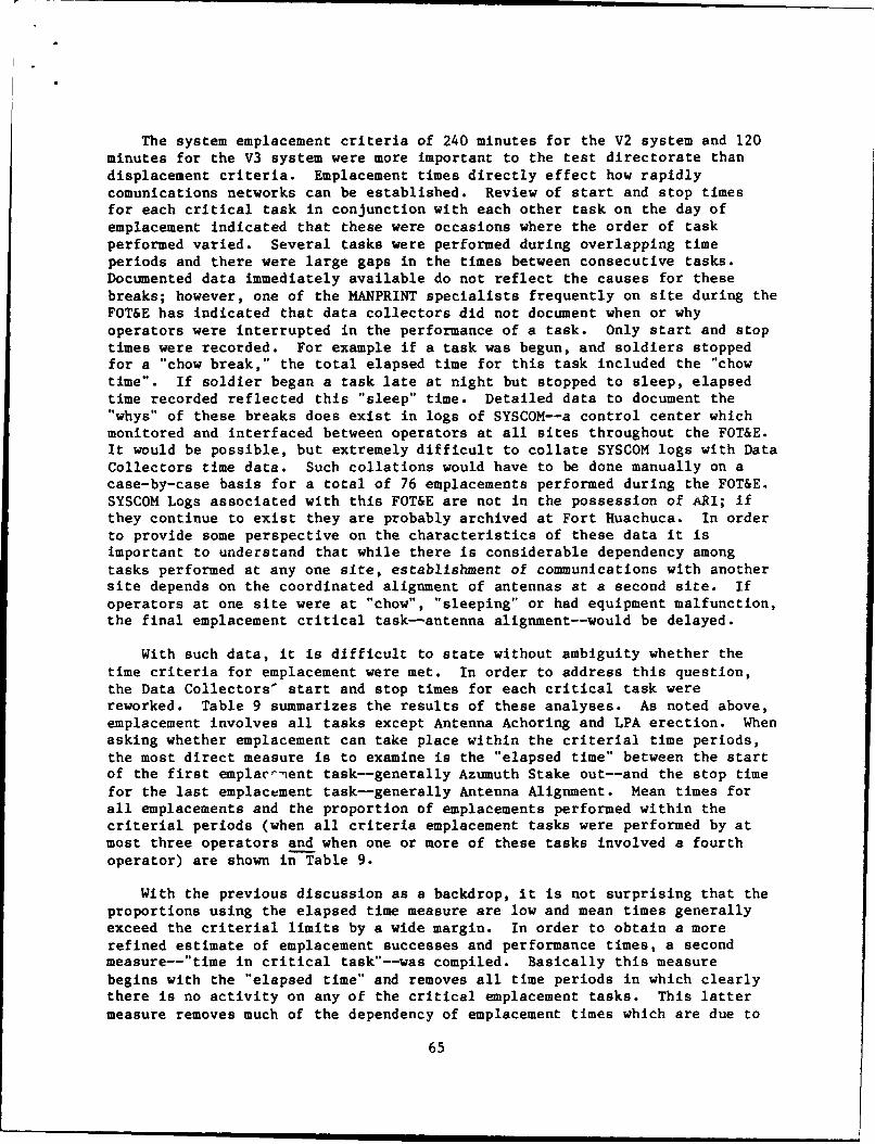
The system emplacement criteria of 240 minutes for the V2 system and 120minutes for the V3 system were more important to the test directorate thandisplacement criteria. Emplacement times directly effect how rapidlycomunications networks can be established. Review of start and stop timesfor each critical task in conjunction with each other task on the day ofemplacement indicated that these were occasions where the order of taskperformed varied. Several tasks were performed during overlapping timeperiods and there were large gaps in the times between consecutive tasks.Documented data immediately available do not reflect the causes for thesebreaks; however, one of the MANPRINT specialists frequently on site during theFOT&E has indicated that data collectors did not document when or whyoperators were interrupted in the performance of a task. Only start and stoptimes were recorded. For example if a task was begun, and soldiers stoppedfor a "chow break," the total elapsed time for this task included the "chowtime". If soldier began a task late at night but stopped to sleep, elapsedtime recorded reflected this "sleep" time. Detailed data to document the"whys" of these breaks does exist in logs of SYSCOM--a control center whichmonitored and interfaced between operators at all sites throughout the FOT&E.It would be possible, but extremely difficult to collate SYSCOM logs with Data
Collectors time data. Such collations would have to be done manually on acase-by-case basis for a total of 76 emplacements performed during the FOT&E.
SYSCOM Logs associated with this FOT&E are not in the possession of ARI; ifthey continue to exist they are probably archived at Fort Huachuca. In orderto provide some perspective on the characteristics of these data it isimportant to understand that while there is considerable dependency amongtasks performed at any one site, establishment of communications with anothersite depends on the coordinated alignment of antennas at a second site. If
operators at one site were at "chow", "sleeping" or had equipment malfunction,the final emplacement critical task--antenna alignment--would be delayed.
With such data, it is difficult to state without ambiguity whether thetime criteria for emplacement were met. In order to address this question,the Data Collectors' start and stop times for each critical task werereworked. Table 9 summarizes the results of these analyses. As noted above,emplacement involves all tasks except Antenna Achoring and LPA erection. Whenasking whether emplacement can take place within the criterial time periods,the most direct measure is to examine is the "elapsed time" between the startof the first emplacr-ent task--generally Azumuth Stake out--and the stop timefor the last emplacement task-generally Antenna Alignment. Mean times forall emplacements and the proportion of emplacements performed within thecriterial periods (when all criteria emplacement tasks were performed by atmost three operators and when one or more of these tasks involved a fourth
operator) are shown in Table 9.
With the previous discussion as a backdrop, it is not surprising that theproportions using the elapsed time measure are low and mean times generallyexceed the criterial limits by a wide margin. In order to obtain a morerefined estimate of emplacement successes and performance times, a secondmeasure--"time in critical task"--was compiled. Basically this measurebegins with the "elapsed time" and removes all time periods in which clearlythere is no activity on any of the critical emplacement tasks. This lattermeasure removes much of the dependency of emplacement times which are due to
65
inactivity at a second site. To the extent tasks begun were completed beforesoldiers went to "chow" or "sleep", this measure provides a better estimateof emplacement time. Using this better measure, it is quite clear that theproportions of criterial emplacement times appear to be considerably largerthan with the "elapsed time" measure, and the mean performance times are aboutfifty percent smaller. The AN/TRC-170 units were originally designed to beoperated by 4-man crews. The Army, in an effort to reduce manpower, testedthe unit with 3-man crews. While there is some indication that a largernumber of operators can meet the emplacement criteria better and somewhat morequickly, the number of observations available upon which to base such aconclusion is relatively small. Tables 5 and 7 provide added indication ofspecific tasks for which more favorable critical task performance times wasobtained with more operators. These data seem to indicate that in order toassess the system emplacement criteria question, an in-depth investigation ofthe time-consuming tasks and 4-man crews is required. In order to reduce thetime-consuming task times, it may be necessary to streamline procedures,modify equipment for materials handling, and examine training. It should benoted that the task times were sampled during Phase III when crewmen were mostexperienced and practiced. Thus, improved training may offer little oppor-tunity to improve crew task performance time. Moreover, several problemswere discussed earlier that directly impact on the task times, such as thelack of walkways on the low-profile pallet, difficulties using the Pionjar toset duckbill anchors, and cramped stowage space for equipment. Having 4-mancrews man the AN/TRC-170 would have several other benefits beyond shorteningtask performance times. The additional benefits include: a driver andcommander for each vehicle, an additional crewman for 24-hour operations, andadditional crewman for perimeter security.
In addition to the items suggested above for further study, there is amore general concern about testing--fidelity to the real world. Thereappears to be a tendency within the test community for tests to be designed tosupport the emerging system. Specifically tests are designed to test theoperational characteristics of the system-in a "test tube"--rather than inthe real world environment for which the system was designed. Results ofanalyses presented in Table 9 suggest that more attention was given to soldiercomfort--sleeping and eating--than might actually occur in a war timeenvironment. If this test were conducted to place priority on making thesystem operational within the time criteria established, it is more likelythat measures of "elapsed time" would coincide with "time in critical task".Perhaps of greater importance, the manpower requirements for "on-task" and"off-task" operation of the system would be more adequately addressed. It isstrongly recommended that as part of any in-depth investigation suggestedabove, the design should incorporate a level of fidelity which permitsmanpower requirements to be more accurately assessed.
66
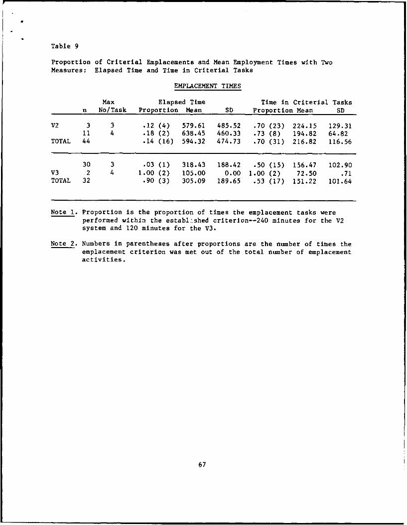
Table 9
Proportion of Criterial Emplacements and Mean Employment Times with Two
Measures: Elapsed Time and Time in Criterial Tasks
EMPLACEMENT TIMES
Max Elapsed Time Time in Criterial Tasksn No/Task Proportion Mean SD Proportion Mean SD
V2 3 3 .12 (4) 579.61 485.52 .70 (23) 224.15 129.3111 4 .18 (2) 638.45 460.33 .73 (8) 194.82 64.82
TOTAL 44 .14 (16) 594.32 474.73 .70 (31) 216.82 116.56
30 3 .03 (1) 318.43 188.42 .50 (15) 156.47 102.90V3 2 4 1.00 (2) 105.00 0.00 1.00 (2) 72.50 .71TOTAL 32 .90 (3) 305.09 189.65 .53 (17) 151.22 101.64
Note 1. Proportion is the proportion of times the emplacement tasks wereperformed within the established criterion--240 minutes for the V2system and 120 minutes for the V3.
Note 2. Numbers in parentheses after proportions are the number of times theemplacement criterion was met out of the total number of emplacementactivities.
67

Discussion
The purpose of the MANPRINT assessment was to identify human factorsengineering, safety, health hazards, training, and manpower problems whoseamelioration or correction could lead to satisfactory or enhanced operationand maintenance of the AN/TRC-170 system. Crew task performance times werecompared to system performance criteria. Twenty-four findings were obtained.
Notably, most MANPRINT findings involved materials handling problemsrelated to the emplacement and displacement of the AN/TRC-170 microwave relaystation. Crewmen only monitor the radio functions after the equipment ispowered up. Thus, there are no complex operating tasks. The AN/TRC-170 radioperformed beyond expectations as a radio relay during the test. However, manyof the problems found with the design of the equipment adversely affected theease of assembly and disassembly. Time-consuming tasks were identified; henceboth task organization and associated equipment characterististics may needreorganization, manpower changes, or equipment modification if emplacementtime criteria are to be met.
The attendees of the MANPRINT scoring conference gave high priorities tonine of the 24 findings. The program manager's participation in the scoringconference should assure that the nine high priority problems are solved.They include the following:
1. The lack of high frequency radios;2. Low mobilizer ground clearance;3. Moving the mobilizer in reverse;4. Discontinuous generator operation;5. Noise levels in the shelters;6. Steps and handrails on trucks;7. Loading and unloading of the low-profile pallet;8. Hearing protection for Pionjar operators; and9. Training for Pionjar operations.
The manpower issue of crew size may not be resolved. However, muchevidence supports the inclusion of a fourth man in the crew. Not only wouldemplacement tasks be performed more rapidly, but vehicle operation, perimetersecurity, and 24-hour operations would be facilitated. The manpower require-ment for maintainers may have to be increased. The total number of main-tainers allocated to the units was three. However, many delays resulted whenmaintainers had to travel great distances between field sites. Duringtactical operations, maintainers may be unable to travel such distances on atimely basis. Crewmen might be authorized to perform additional minor main-tenance tasks, especially if the Army decides to authorize only one mechanicfor every two AN/TRC units.
The MANPRINT findings for the AN/TRC-170 all involved areas that can beimproved. Crewmen and maintainers are likely to perform tasks more rapidlyonce certain equipment design features are improved.
68
I
REFERENCES
Bowser, S. (1986, April). MANPRINT assessment annex: AN/TRC-170 digitaltroposcatter radio system, MANPRINT data collection forms and raw data.San Diego, CA: Bowser and Associates.
Heuckeroth, 0. H. (1988). Training assessment: The AN/TRC-170 digitaltroposcatter radio system. Alexandria, VA: U.S. Army Research Institutefor the Behavioral and Social Sciences.
U.S. Army Test and Evaluation Command (1983, November). Test operationsprocedures, human factors engineering, Part I--Test procedures, Part II--HEDGE (TOP 1-2-610, Parts I and II). Aberdeen Proving Ground, MD.
69