Embed Size (px)
Citation preview

Date: October 2018
Essence – Kernel and Language for Software Engineering Methods
Version 1.2
__________________________________________________
OMG Document Number: formal/18-10-02
Standard document URL: https://www.omg.org/spec/Essence/
Machine Readable File(s):
https://www.omg.org/spec/Essence/20150601/Essence.xmi
_________________________________________________

Copyright © 2013–2018, Data Access Technologies (Model Driven Solutions) Copyright © 2013–2015, Florida Atlantic University Copyright © 2013–2015, Fujitsu Copyright © 2013–2015, Fujitsu Services Copyright © 2013–2018, Ivar Jacobson International AB Copyright © 2013–2015, KTH Royal Institute of Technology Copyright © 2013–2015, Metamaxim Ltd. Copyright © 1997–2018, Object Management Group Copyright © 2013–2015, PEM Systems Copyright © 2013–2015, Stiftelsen SINTEF Copyright © 2013–2015, University of Duisburg-Essen
USE OF SPECIFICATION - TERMS, CONDITIONS & NOTICES The material in this document details an Object Management Group specification in accordance with the terms, conditions and notices set forth below. This document does not represent a commitment to implement any portion of this specification in any company's products. The information contained in this document is subject to change without notice.
LICENSES The companies listed above have granted to the Object Management Group, Inc. (OMG) a nonexclusive, royalty-free, paid up, worldwide license to copy and distribute this document and to modify this document and distribute copies of the modified version. Each of the copyright holders listed above has agreed that no person shall be deemed to have infringed the copyright in the included material of any such copyright holder by reason of having used the specification set forth herein or having conformed any computer software to the specification.
Subject to all of the terms and conditions below, the owners of the copyright in this specification hereby grant you a fully-paid up, non-exclusive, nontransferable, perpetual, worldwide license (without the right to sublicense), to use this specification to create and distribute software and special purpose specifications that are based upon this specification, and to use, copy, and distribute this specification as provided under the Copyright Act; provided that: (1) both the copyright notice identified above and this permission notice appear on any copies of this specification; (2) the use of the specifications is for informational purposes and will not be copied or posted on any network computer or broadcast in any media and will not be otherwise resold or transferred for commercial purposes; and (3) no modifications are made to this specification. This limited permission automatically terminates without notice if you breach any of these terms or conditions. Upon termination, you will destroy immediately any copies of the specifications in your possession or control.
PATENTS The attention of adopters is directed to the possibility that compliance with or adoption of OMG specifications may require use of an invention covered by patent rights. OMG shall not be responsible for identifying patents for which a license may be required by any OMG specification, or for conducting legal inquiries into the legal validity or scope of those patents that are brought to its attention. OMG specifications are prospective and advisory only. Prospective users are responsible for protecting themselves against liability for infringement of patents.
GENERAL USE RESTRICTIONS Any unauthorized use of this specification may violate copyright laws, trademark laws, and communications regulations and statutes. This document contains information which is protected by copyright. All Rights Reserved. No part of this work covered by copyright herein may be reproduced or used in any form or by any means--graphic, electronic, or mechanical, including photocopying, recording, taping, or information storage and retrieval systems--without permission of the copyright owner.

DISCLAIMER OF WARRANTY WHILE THIS PUBLICATION IS BELIEVED TO BE ACCURATE, IT IS PROVIDED "AS IS" AND MAY CONTAIN ERRORS OR MISPRINTS. THE OBJECT MANAGEMENT GROUP AND THE COMPANIES LISTED ABOVE MAKE NO WARRANTY OF ANY KIND, EXPRESS OR IMPLIED, WITH REGARD TO THIS PUBLICATION, INCLUDING BUT NOT LIMITED TO ANY WARRANTY OF TITLE OR OWNERSHIP, IMPLIED WARRANTY OF MERCHANTABILITY OR WARRANTY OF FITNESS FOR A PARTICULAR PURPOSE OR USE. IN NO EVENT SHALL THE OBJECT MANAGEMENT GROUP OR ANY OF THE COMPANIES LISTED ABOVE BE LIABLE FOR ERRORS CONTAINED HEREIN OR FOR DIRECT, INDIRECT, INCIDENTAL, SPECIAL, CONSEQUENTIAL, RELIANCE OR COVER DAMAGES, INCLUDING LOSS OF PROFITS, REVENUE, DATA OR USE, INCURRED BY ANY USER OR ANY THIRD PARTY IN CONNECTION WITH THE FURNISHING, PERFORMANCE, OR USE OF THIS MATERIAL, EVEN IF ADVISED OF THE POSSIBILITY OF SUCH DAMAGES.
The entire risk as to the quality and performance of software developed using this specification is borne by you. This disclaimer of warranty constitutes an essential part of the license granted to you to use this specification.
RESTRICTED RIGHTS LEGEND Use, duplication or disclosure by the U.S. Government is subject to the restrictions set forth in subparagraph (c) (1) (ii) of The Rights in Technical Data and Computer Software Clause at DFARS 252.227-7013 or in subparagraph (c)(1) and (2) of the Commercial Computer Software - Restricted Rights clauses at 48 C.F.R. 52.227-19 or as specified in 48 C.F.R. 227-7202-2 of the DoD F.A.R. Supplement and its successors, or as specified in 48 C.F.R. 12.212 of the Federal Acquisition Regulations and its successors, as applicable. The specification copyright owners are as indicated above and may be contacted through the Object Management Group, 109 Highland Avenue, Needham, MA 02494, U.S.A.
TRADEMARKS CORBA®, CORBA logos®, FIBO®, Financial Industry Business Ontology®, FINANCIAL INSTRUMENT GLOBAL IDENTIFIER®, IIOP®, IMM®, Model Driven Architecture®, MDA®, Object Management Group®, OMG®, OMG Logo®, SoaML®, SOAML®, SysML®, UAF®, Unified Modeling Language®, UML®, UML Cube Logo®, VSIPL®, and XMI® are registered trademarks of the Object Management Group, Inc.
For a complete list of trademarks, see: http://www.omg.org/legal/tm_list.htm. All other products or company names mentioned are used for identification purposes only, and may be trademarks of their respective owners.
COMPLIANCE The copyright holders listed above acknowledge that the Object Management Group (acting itself or through its designees) is and shall at all times be the sole entity that may authorize developers, suppliers and sellers of computer software to use certification marks, trademarks or other special designations to indicate compliance with these materials.
Software developed under the terms of this license may claim compliance or conformance with this specification if and only if the software compliance is of a nature fully matching the applicable compliance points as stated in the specification. Software developed only partially matching the applicable compliance points may claim only that the software was based on this specification, but may not claim compliance or conformance with this specification. In the event that testing suites are implemented or approved by Object Management Group, Inc., software developed using this specification may claim compliance or conformance with the specification only if the software satisfactorily completes the testing suites.

OMG’S ISSUE REPORTING PROCEDURE All OMG specifications are subject to continuous review and improvement. As part of this process we encourage readers to report any ambiguities, inconsistencies, or inaccuracies they may find by completing the Issue Reporting Form listed on the main web page http://www.omg.org, under Documents, Report a Bug/Issue.

Kernel and Language for Software Engineering Methods (Essence), v1.2 i
Table of Contents
Preface .................................................................................................................................................. xi 1 Scope ...............................................................................................................................................1 2 Conformance ...................................................................................................................................1
2.1 Conformance Classes ................................................................................................................1 2.2 Practice Description Conformance ...........................................................................................2
2.2.1 Overview ............................................................................................................................2 2.2.2 Level 1: Narrative ..............................................................................................................2 2.2.3 Level 2: Practice Description Interchange .........................................................................2 2.2.4 Level 3: Practice Actionable and Trackable .......................................................................2
2.3 Tool Conformance ....................................................................................................................3 3 Normative References .....................................................................................................................3 4 Terms and Definitions .....................................................................................................................4 5 Abbreviations...................................................................................................................................6 6 Additional Information ....................................................................................................................6
6.1 Submitting Organizations .........................................................................................................6 6.2 Supporting Organizations .........................................................................................................7 6.3 Acknowledgements ...................................................................................................................7
7 Overview of the Specification .........................................................................................................9 7.1 Introduction ...............................................................................................................................9 7.2 Key Features .............................................................................................................................9 7.3 The Method Architecture ........................................................................................................10 7.4 Why a Kernel and a Language? .............................................................................................. 11
7.4.1 The Role of the Kernel ..................................................................................................... 11 7.4.2 The Role of the Language ................................................................................................12
7.5 How to Read this Specification ...............................................................................................12 8 Kernel Specification ......................................................................................................................15
8.1 Overview .................................................................................................................................15 8.1.1 What is the Kernel? ..........................................................................................................15 8.1.2 What is in the Kernel?......................................................................................................15

ii Kernel and Language for Software Engineering Methods (Essence), v1.2
8.1.3 Organizing the Kernel ......................................................................................................16 8.1.4 Alphas: The Things to Work With ...................................................................................16 8.1.5 Activity Spaces: The Things to Do ..................................................................................18 8.1.6 Competencies: The Abilities Needed ...............................................................................20
8.2 The Customer Area of Concern ..............................................................................................23 8.2.1 Introduction ......................................................................................................................23 8.2.2 Alphas ..............................................................................................................................23
8.2.2.1 Stakeholders ..............................................................................................................23 8.2.2.2 Opportunity ...............................................................................................................27
8.2.3 Activity Spaces ................................................................................................................31 8.2.3.1 Explore Possibilities..................................................................................................32 8.2.3.2 Understand Stakeholder Needs .................................................................................32 8.2.3.3 Ensure Stakeholder Satisfaction ...............................................................................32 8.2.3.4 Use the System ..........................................................................................................33
8.2.4 Competencies ...................................................................................................................33 8.2.4.1 Stakeholder Representation ......................................................................................33
8.3 The Solution Area of Concern ................................................................................................34 8.3.1 Introduction ......................................................................................................................34 8.3.2 Alphas ..............................................................................................................................35
8.3.2.1 Requirements ............................................................................................................35 8.3.2.2 Software System .......................................................................................................39
8.3.3 Activity Spaces ................................................................................................................43 8.3.3.1 Understand the Requirements ...................................................................................43 8.3.3.2 Shape the System ......................................................................................................44 8.3.3.3 Implement the System...............................................................................................44 8.3.3.4 Test the System .........................................................................................................45 8.3.3.5 Deploy the System ....................................................................................................45 8.3.3.6 Operate the System ...................................................................................................45
8.3.4 Competencies ...................................................................................................................46 8.3.4.1 Analysis.....................................................................................................................46 8.3.4.2 Development .............................................................................................................47

Kernel and Language for Software Engineering Methods (Essence), v1.2 iii
8.3.4.3 Testing .......................................................................................................................48 8.4 The Endeavor Area of Concern ...............................................................................................49
8.4.1 Introduction ......................................................................................................................49 8.4.2 Alphas ..............................................................................................................................49
8.4.2.1 Team ..........................................................................................................................49 8.4.2.2 Work ..........................................................................................................................53 8.4.2.3 Way-of-Working .......................................................................................................57
8.4.3 Activity Spaces ................................................................................................................61 8.4.3.1 Prepare to do the Work ..............................................................................................61 8.4.3.2 Coordinate Activity ...................................................................................................61 8.4.3.3 Support the Team ......................................................................................................62 8.4.3.4 Track Progress ...........................................................................................................62 8.4.3.5 Stop the Work ............................................................................................................62
8.4.4 Competencies ...................................................................................................................63 8.4.4.1 Leadership .................................................................................................................63 8.4.4.2 Management ..............................................................................................................64
9 Language Specification .................................................................................................................67 9.1 Specification Technique ..........................................................................................................67
9.1.1 Different Meta-Levels ......................................................................................................67 9.1.2 Specification Format ........................................................................................................67 9.1.3 Notation Used ..................................................................................................................68
9.2 Conceptual Overview of the Language ...................................................................................68 9.3 Language Elements and Language Model ..............................................................................70
9.3.1 Overview ..........................................................................................................................70 9.3.2 Foundation .......................................................................................................................71
9.3.2.1 Overview ...................................................................................................................71 9.3.2.2 BasicElement ............................................................................................................73 9.3.2.3 Checkpoint ................................................................................................................74 9.3.2.4 ElementGroup ...........................................................................................................75 9.3.2.5 EndeavorAssociation ................................................................................................76 9.3.2.6 EndeavorProperty .....................................................................................................76
iv Kernel and Language for Software Engineering Methods (Essence), v1.2
9.3.2.7 ExtensionElement .....................................................................................................77 9.3.2.8 Kernel ........................................................................................................................78 9.3.2.9 LanguageElement .....................................................................................................79 9.3.2.10 Library.......................................................................................................................80 9.3.2.11 MergeResolution .......................................................................................................80 9.3.2.12 Method ......................................................................................................................81 9.3.2.13 Pattern .......................................................................................................................81 9.3.2.14 PatternAssociation ....................................................................................................82 9.3.2.15 Practice ......................................................................................................................83 9.3.2.16 PracticeAsset .............................................................................................................85 9.3.2.17 Resource ....................................................................................................................85 9.3.2.18 Tag .............................................................................................................................86
9.3.3 AlphaAndWorkProduct ....................................................................................................87 9.3.3.1 Overview ...................................................................................................................87 9.3.3.2 Alpha .........................................................................................................................88 9.3.3.3 AlphaAssociation ......................................................................................................89 9.3.3.4 AlphaContainment ....................................................................................................90 9.3.3.5 LevelOfDetail ...........................................................................................................91 9.3.3.6 State...........................................................................................................................91 9.3.3.7 WorkProduct .............................................................................................................92 9.3.3.8 WorkProductManifest ...............................................................................................93
9.3.4 ActivitySpaceAndActivity ...............................................................................................94 9.3.4.1 Overview ...................................................................................................................94 9.3.4.2 AbstractActivity ........................................................................................................95 9.3.4.3 Action ........................................................................................................................96 9.3.4.4 ActionKind ................................................................................................................96 9.3.4.5 Activity .....................................................................................................................97 9.3.4.6 ActivityAssociation...................................................................................................98 9.3.4.7 ActivitySpace ............................................................................................................99 9.3.4.8 Approach ...................................................................................................................99 9.3.4.9 CompletionCriterion ...............................................................................................100

Kernel and Language for Software Engineering Methods (Essence), v1.2 v
9.3.4.10 Criterion ..................................................................................................................100 9.3.4.11 EntryCriterion .........................................................................................................101
9.3.5 Competency ...................................................................................................................102 9.3.5.1 Overview .................................................................................................................102 9.3.5.2 Competency ............................................................................................................102 9.3.5.3 CompetencyLevel ...................................................................................................103
9.3.6 UserDefinedTypes ..........................................................................................................104 9.3.6.1 Overview .................................................................................................................104 9.3.6.2 TypedPattern ...........................................................................................................104 9.3.6.3 TypedResource ........................................................................................................105 9.3.6.4 TypedTag .................................................................................................................105 9.3.6.5 UserDefinedType ....................................................................................................106
9.3.7 View ...............................................................................................................................107 9.3.7.1 Overview .................................................................................................................107 9.3.7.2 FeatureSelection ......................................................................................................108 9.3.7.3 ViewSelection .........................................................................................................108
9.4 Composition and Modification ............................................................................................. 111 9.4.1 Introduction .................................................................................................................... 111 9.4.2 Notations and Conventions ............................................................................................ 112 9.4.3 Extending ....................................................................................................................... 112
9.4.3.1 Basic Extension Algorithm ..................................................................................... 112 9.4.3.2 Renaming and Suppression ..................................................................................... 113 9.4.3.3 Standard Extension Functions................................................................................. 113 9.4.3.4 Precedence and Chaining ........................................................................................ 113
9.4.4 Merging .......................................................................................................................... 113 9.4.4.1 Overview ................................................................................................................. 113 9.4.4.2 Basic Merging Algorithm ....................................................................................... 114 9.4.4.3 Merge Conflict Resolution ...................................................................................... 114 9.4.4.4 Standard Merge Resolution Functions .................................................................... 115 9.4.4.5 Precedence and Chaining ........................................................................................ 115
9.4.5 Example ......................................................................................................................... 115

vi Kernel and Language for Software Engineering Methods (Essence), v1.2
9.5 Dynamic Semantics .............................................................................................................. 119 9.5.1 Introduction .................................................................................................................... 119 9.5.2 Domain classes ............................................................................................................... 119
9.5.2.1 Recap of Metamodeling Levels .............................................................................. 119 9.5.2.2 Naming Convention ................................................................................................120 9.5.2.3 Abstract Superclasses..............................................................................................120
9.5.3 Operational Semantics ...................................................................................................122 9.5.3.1 Overview .................................................................................................................122 9.5.3.2 Populating the Level 0 Model .................................................................................122 9.5.3.3 Determining the Overall State ................................................................................123 9.5.3.4 Generating Guidance ..............................................................................................123 9.5.3.5 Formal definition of the Guidance Function ...........................................................124 9.5.3.6 Further functions .....................................................................................................125
9.6 Adaptation .............................................................................................................................126 9.6.1 Alignment of Level 0 and Level 1 .................................................................................126 9.6.2 Adaptation Approach .....................................................................................................127 9.6.3 Internal Migration ..........................................................................................................127 9.6.4 External Migration .........................................................................................................128
9.7 Graphical Syntax ...................................................................................................................128 9.7.1 Specification Format ......................................................................................................128 9.7.2 Relevant Symbols and Diagram Interchange Metamodel .............................................128 9.7.3 Default Notation for Meta-Class Constructs..................................................................129 9.7.4 View 1: Alphas and their States .....................................................................................130
9.7.4.1 Alpha .......................................................................................................................130 9.7.4.2 Alpha Association ...................................................................................................130 9.7.4.3 Kernel ......................................................................................................................131 9.7.4.4 State.........................................................................................................................132 9.7.4.5 State Successor ........................................................................................................132 9.7.4.6 Diagrams .................................................................................................................132 9.7.4.7 Cards .......................................................................................................................134
9.7.5 View 2: Sub-Alphas and Work Products ........................................................................139

Kernel and Language for Software Engineering Methods (Essence), v1.2 vii
9.7.5.1 Work Product ..........................................................................................................139 9.7.5.2 Alpha Containment .................................................................................................139 9.7.5.3 Work Product Manifest ...........................................................................................140 9.7.5.4 Level of Detail ........................................................................................................141 9.7.5.5 Level of Detail Successor .......................................................................................142 9.7.5.6 Practice ....................................................................................................................142 9.7.5.7 Diagrams .................................................................................................................143 9.7.5.8 Cards .......................................................................................................................145
9.7.6 View 3: Activity Spaces and Activities ..........................................................................149 9.7.6.1 Activity ...................................................................................................................149 9.7.6.2 Activity Space .........................................................................................................149 9.7.6.3 Activity Association (“part-of” kind) ......................................................................150 9.7.6.4 Activity Association (other than the “part-of” kind) ...............................................151 9.7.6.5 Competency ............................................................................................................152 9.7.6.6 Competency Level ..................................................................................................152 9.7.6.7 Diagrams .................................................................................................................153 9.7.6.8 Cards .......................................................................................................................154
9.7.7 View 4: Patterns .............................................................................................................160 9.7.7.1 Pattern .....................................................................................................................160 9.7.7.2 Pattern Association..................................................................................................161 9.7.7.3 Diagrams .................................................................................................................162 9.7.7.4 Cards .......................................................................................................................162
9.8 Textual Syntax ......................................................................................................................164 9.8.1 Overview ........................................................................................................................164 9.8.2 Rules ..............................................................................................................................164
9.8.2.1 Notation...................................................................................................................164 9.8.2.2 Root Elements .........................................................................................................165 9.8.2.3 Element Groups ......................................................................................................166 9.8.2.4 Kernel Elements ......................................................................................................167 9.8.2.5 Practice Elements ....................................................................................................168 9.8.2.6 Auxiliary Elements .................................................................................................169

viii Kernel and Language for Software Engineering Methods (Essence), v1.2
9.8.3 Examples ........................................................................................................................170 Annex A: Optional Kernel Extensions ...............................................................................................175
A.1 Introduction ...........................................................................................................................175 A.1.1 Acknowledgements ........................................................................................................175 A.1.2 Overview ........................................................................................................................175 A.1.3 Why the Focus on Adding Alphas? ................................................................................175 A.1.4 Why are the Subordinate Alphas not included in the Kernel? .......................................176 A.1.5 How do you use the Kernel Extensions? .......................................................................176
A.2 Business Analysis Extension.................................................................................................176 A.2.1 Introduction ....................................................................................................................176 A.2.2 Alphas ............................................................................................................................176
A.2.2.1 Stakeholder Representative .....................................................................................176 A.2.2.2 Need ........................................................................................................................181
A.3 Development Extensions ......................................................................................................184 A.3.1 Introduction ....................................................................................................................184 A.3.2 Alphas ............................................................................................................................185
A.3.2.1 Requirement Item ....................................................................................................185 A.3.2.2 Bug ..........................................................................................................................190 A.3.2.3 Software System Element .......................................................................................193
A.4 Task Management Extension ................................................................................................197 A.4.1 Introduction ....................................................................................................................197 A.4.2 Alphas ............................................................................................................................198
A.4.2.1 Team Member .........................................................................................................198 A.4.2.2 Task .........................................................................................................................201 A.4.2.3 Practice Adoption ....................................................................................................204
Annex B: KUALI-BEH Kernel Extension ........................................................................................209 B.1 Introduction ...........................................................................................................................209
B.1.1 Acknowledgements ........................................................................................................209 B.2 Alphas ...................................................................................................................................209
B.2.1 Overview ........................................................................................................................209 B.2.2 Practice Authoring ......................................................................................................... 211

Kernel and Language for Software Engineering Methods (Essence), v1.2 ix
B.2.3 Method Authoring ..........................................................................................................218 B.2.4 Practice Instance ............................................................................................................224 B.2.5 Method Enactment .........................................................................................................231
Annex C: Alignment with SPEM 2.0 .................................................................................................243 C.1 Overview ...............................................................................................................................243 C.2 Key Objectives of SPEM and Essence .................................................................................243 C.3 Comparison of SPEM and Essence and Recommendations .................................................244 C.4 Migrating SPEM to Essence .................................................................................................246
C.4.1 Introduction ....................................................................................................................246 C.4.2 Overall Approach to a Manual Migration Procedure .....................................................246 C.4.3 Transforming SPEM Managed Content .........................................................................248 C.4.4 Transforming SPEM Method Content ...........................................................................250 C.4.5 Transforming SPEM Processes ......................................................................................252 C.4.6 SPEM Activity vs. Essence Activity Space and Activity ...............................................253 C.4.7 A Note on Transforming SPEM Methods and Plugins ..................................................255
Annex D: Alignment with ISO 24744 ...............................................................................................257 D.1 Introduction ...........................................................................................................................257 D.2 Alignment with ISO 24744 ...................................................................................................257
D.2.1 Different metamodel architecture ..................................................................................257 D.2.2 Different writing system ................................................................................................258 D.2.3 Definition of an ISO 24744 Kernel extension ...............................................................259
D.3 Overview of ISO 24744 features ..........................................................................................260 Annex E: Practice Examples ..............................................................................................................265
E.1 Introduction ...........................................................................................................................265 E.2 Practices ................................................................................................................................265
E.2.1 Overview ........................................................................................................................265 E.2.2 Scrum .............................................................................................................................265
E.2.2.1 Overview .................................................................................................................265 E.2.2.2 Practice ....................................................................................................................265 E.2.2.3 Alphas .....................................................................................................................267 E.2.2.4 Work Products .........................................................................................................271

x Kernel and Language for Software Engineering Methods (Essence), v1.2
E.2.2.5 Activities .................................................................................................................274 E.2.2.6 Roles .......................................................................................................................277
E.2.3 User Story ......................................................................................................................278 E.2.3.1 Practice ....................................................................................................................278 E.2.3.2 Work Products .........................................................................................................278 E.2.3.3 Activities .................................................................................................................280
E.2.4 Multi-phase Waterfall ....................................................................................................281 E.2.4.1 Activities .................................................................................................................281 E.2.4.2 Alpha Extensions for Multi-Phase Waterfall Requirements ...................................285 E.2.4.3 Lifecycle Diagram for Multi-Phase Waterfall Requirements Alpha Extensions ....286 E.2.4.4 Extensions of Requirement Item Alpha for Tracking Individual Multi-Phase Waterfall Requirement Items .................................................................................................286
E.2.5 Lifecycle Examples ........................................................................................................288 E.2.5.1 The Unified Process Lifecycle ................................................................................289 E.2.5.2 The Waterfall Lifecycle ..........................................................................................290 E.2.5.3 A set of complementary application development lifecycles .................................291
E.3 Composing Practices into Methods ......................................................................................296 E.3.1 Composing Scrum and User Story .................................................................................296
E.4 Enactment of Methods ..........................................................................................................297 E.4.1 The Initial Set of Cards ..................................................................................................297 E.4.2 Determining the Overall State for the First Time ..........................................................298 E.4.3 Generating Guidance for the First Time ........................................................................299 E.4.4 Updating the Overall State .............................................................................................299

Kernel and Language for Software Engineering Methods (Essence), v1.2 xi
Preface
OMG Founded in 1989, the Object Management Group, Inc. (OMG) is an open membership, not-for-profit computer industry standards consortium that produces and maintains computer industry specifications for interoperable, portable, and reusable enterprise applications in distributed, heterogeneous environments. Membership includes Information Technology vendors, end users, government agencies, and academia.
OMG member companies write, adopt, and maintain its specifications following a mature, open process. OMG’s specifications implement the Model Driven Architecture® (MDA®), maximizing ROI through a full-lifecycle approach to enterprise integration that covers multiple operating systems, programming languages, middleware and networking infrastructures, and software development environments. OMG’s specifications include: UML® (Unified Modeling Language™); CORBA® (Common Object Request Broker Architecture); CWM™ (Common Warehouse Metamodel); and industry-specific standards for dozens of vertical markets.
More information on the OMG is available at http://www.omg.org/.
OMG Specifications As noted, OMG specifications address middleware, modeling and vertical domain frameworks. All OMG Specifications are available from the OMG website at: https://www.omg.org/spec All of OMG’s formal specifications may be downloaded without charge from our website. (Products implementing OMG specifications are available from individual suppliers.) Copies of specifications, available in PostScript and PDF format, may be obtained from the Specifications Catalog cited above or by contacting the Object Management Group, Inc. at: OMG Headquarters 109 Highland Avenue Needham, MA 02494 USA Tel: +1-781-444-0404 Fax: +1-781-444-0320 Email: [email protected]
Certain OMG specifications are also available as ISO standards. Please consult http://www.iso.org
Issues All OMG specifications are subject to continuous review and improvement. As part of this process we encourage readers to report any ambiguities, inconsistencies, or inaccuracies they may find by completing the Issue Reporting Form listed on the main web page http://www.omg.org, under Documents, Report a Bug/Issue.

xii Kernel and Language for Software Engineering Methods (Essence), v1.2
This page intentionally left blank.

Kernel and Language for Software Engineering Methods (Essence), v1.2 1
1 Scope This document provides comprehensive definitions and descriptions of the kernel and the language for software engineering methods.
The Kernel provides the common ground for defining software development practices. It includes the essential elements that are always prevalent in every software engineering endeavor, such as Requirements, Software System, Team, and Work. These elements have states representing progress and health, so as the endeavor moves forward the states associated with these elements progress. The Kernel among other things helps practitioners (e.g., architects, designers, developers, testers, developers, requirements engineers, process engineers, project managers, etc.) compare methods and make better decisions about their practices.
The Kernel is described using the Language, which defines abstract syntax, dynamic semantics, graphic syntax, and textual syntax. The Language supports composing two practices to form a new practice, and composing practices into a method, and the enactment of methods.
This document addresses the mandatory requirements of the Kernel, the Language, and Practice in the following:
• It defines the Kernel and its organizations into three areas of concerns: Customer, Solution, and Endeavor.
• It defines the Kernel Alphas (i.e., the essential things to work with), and Activity Spaces (i.e., the essential things to do).
• It describes the Language specification, Language elements, and Language model.
• It defines Language Dynamic Semantics, Graphical Syntax, and Textual Syntax.
• It describes examples of composing Practices into Methods, and Enactment of Methods.
2 Conformance
2.1 Conformance Classes The normative requirements in this specification are contained in Clause 8, Clause 9, and Annex A. This specification provides two conformance classes. See also the definitions given in Clause 4 of important terms used in a specific technical sense in this specification.
• Practice Description Conformance. This class applies to the description of practices, defined using the Essence language, as specified in Clause 9.
• Tool Conformance. This class applies to tools that provide a means for the definition of description practices in the Essence language, using the Essence kernel, as specified in Clause 8, with optional extensions given in Annex A.
A claim of Essence conformance shall declare the practice or tool for which conformance is claimed. Conformance is achieved by demonstrating that the requirements for the appropriate conformance class have been satisfied, as further discussed in the following subclauses.

2 Kernel and Language for Software Engineering Methods (Essence), v1.2
2.2 Practice Description Conformance
2.2.1 Overview
This conformance class applies to published practice descriptions defined using the Essence language, as specified in Clause 9. It provides a clear indication of what can be done with the practice description. One of three levels of conformance may be claimed for a practice description, as further described below.
NOTE: These practice description conformance levels are not associated with a practice; they are a measure of the level of detail with which the practice has been described. It is quite possible for the same practice to be described at all the different conformance levels, for example Scrum could be described by different authors at different conformance levels. It is also possible for teams to use practices which are described at different conformance levels, for example a team could have their much used development and requirement practices at level 3 as these areas are important for them to monitor and track, and their project kick-off practices at level 1 as it is not as important to track their progress and they are typically only performed once by the team.
2.2.2 Level 1: Narrative
Practice descriptions defined at this conformance level use the conceptual elements of the Essence language as a framework for structuring their text. All of the elements in the practice are expressed correctly according to the language; for example all the work products appear as work products and all the activities appear as activities. Beyond this simple classification of the elements in the practice there are no other constraints or invariants.
Once published practices at this level can be referenced by other practices but cannot be exchanged between tools or automatically composed with other practices. Practices described at this level are typically just free format text and there is no XMI interchange format for sharing or composing them.
2.2.3 Level 2: Practice Description Interchange
Practice descriptions defined at this level use the full expressive quality of the language. Everything is typed properly and uses any applicable language element attributes and associations correctly; for example all the elements will have names and brief descriptions conformant with the language rules and all associations between the elements will be queryable and traversable.
Level 2 practices can be exchanged between tools in XMI. This formal use of the language allows the practices to be composed with the kernel and other practices. Practice descriptions at this level are highly structured and will require specialist authoring or modeling tools to produce.
Level 2 practice descriptions add rigor and XMI interchange to Level 1. This provides the consistency and robustness to all tools to “do things” with them. They can read, manipulate and compose the practices but a person is needed to "action" the resulting composition.
2.2.4 Level 3: Practice Actionable and Trackable
Practice descriptions defined at this level use the full power of the language to ensure they are prepared to be automatically actioned and tracked. For example there will always be an Alpha with a fully defined state machine with a complete set of checklists either contained in, or extended by the practice and all activities will be clearly related to the Alpha state progressions that they enable.

Kernel and Language for Software Engineering Methods (Essence), v1.2 3
Like Level 2 practice descriptions, level 3 practice descriptions can be exchanged between tools using XMI, and like the level 2 practice descriptions they can be composed with the kernel and other practice descriptions. Practice descriptions at this level are highly structured and will require specialist authoring or modeling tools to produce.
Level 3 practice descriptions add additional detail and precision over and above that needed for practice descriptions defined at Level 2. The additional information ensures full support for the language’s dynamic semantics enabling tools to provide more sophisticated features such as real-time alpha state tracking, task generation, pattern matching, and completeness checking.
2.3 Tool Conformance This conformance class applies to tools that provide the ability to define practices and methods using the Essence language. As defined in 9.3.2.8, the Essence language Foundation includes the ability to define a kernel as “a set of elements used to form a common ground for describing a software engineering endeavor” and, as specified in 9.3.2.12, a method must be defined based on a specific kernel. While the Essence language provides this general capability for defining and using kernels, a tool may only claim conformance to this specification if it provides both the ability to define methods and practices in the Essence language and a built-in definition of the Essence kernel that may be used in the definition of methods. Specifically:
• The tool shall implement the entire Essence kernel, in the sense of providing a definition of the kernel in the Essence language, as specified in Clause 8, and allowing this kernel to be used as the base kernel for methods defined using the tool (per 9.3.2.12).
• Any practice description produced by the tool shall conform to the requirements for the Essence language, as specified in Clause 9, at any one of the conformance levels defined in 2.2.
For a tool that conforms to this specification as defined above, conformance may also be additionally claimed for one or more of the optional kernel extensions specified in Annex A.
• A tool conforms to the Essence Business Analysis Extension if it implements the entire Business Analysis Extension, as specified in A.2, allowing the Essence kernel so extended to be used as the base kernel for method definitions.
• A tool conforms to the Essence Development Extension if it implements the entire Development Extension, as specified in A.3, allowing the Essence kernel so extended to be used as the base kernel for method definitions.
• A tool conforms to the Essence Task Management Extension if it implements the entire Task Management Extension, as specified in A.4, allowing the Essence kernel so extended to be used as the base kernel for method definitions.
3 Normative References The following normative documents contain provisions which, through reference in this text, constitute provisions of this specification. For dated references, subsequent amendments to, or revisions of, any of these publications do not apply.
• OMG Meta Object Facility (MOF) Core Specification, Version 2.4.1, OMG Document formal/2011-08-07, https://www.omg.org/spec/MOF/2.4.1/
• OMG Unified Modeling Language (OMG UML), Infrastructure, Version 2.4.1, OMG Document formal/2011-08-05, https://www.omg.org/spec/UML/2.4.1/Infrastructure/PDF/

4 Kernel and Language for Software Engineering Methods (Essence), v1.2
• Diagram Definition (DD), Version 1.0, OMG Document formal/2012-07-01, https://www.omg.org/spec/DD/1.0/
• ISO/IEC 13817-1:1996, Information technology -- Programming languages, their environments and system software interfaces -- Vienna Development Method -- Specification Language -- Part 1: Base language. http://www.iso.org/iso/iso_catalogue/catalogue_tc/catalogue_detail.htm?csnumber=22988
4 Terms and Definitions For the purposes of this specification, the following terms and definitions apply.
Activity An activity defines one or more kinds of work items and gives guidance on how to perform these.
Activity space A placeholder for something to be done in the software engineering endeavor; a placeholder may consist of zero to many activities.
Alpha An essential element of the software engineering endeavor that is relevant to an assessment of the progress and health of the endeavor. Alpha is an acronym for an Abstract-Level Progress Health Attribute
Alpha association An alpha association defines a relationship between two alphas.
Area of concern Elements in kernels or practices may be divided into a collection of main areas of concern that a software engineering endeavor has to pay special attention to. All elements fall into at most one of these.
Check list item A check list item is an item in a check list that needs to be verified in a state.
Competency A competency encompasses the abilities, capabilities, attainments, knowledge, and skills necessary to do a certain kind of work.
A competency defines a sequence of competency levels ranging from a minimum level of competency to a maximum level. Typically, the levels range from 0–assists to 5–innovates. (See 8.1.6 and 9.3.5.)
Constraints Restrictions, policies, or regulatory requirements the team must comply with.
Enactment The act of applying a method for some particular purpose, typically an endeavor.

Kernel and Language for Software Engineering Methods (Essence), v1.2 5
Endeavor An activity or set of activities directed towards a goal.
Invariant An invariant is a proposition about an instance of a language element which is true if the instance is used in a language construct as intended by the specification.
Kernel A kernel is a set of elements used to form a common ground for describing a software engineering endeavor.
Method A Method is the composition of a Kernel and a set of Practices to fulfill a specific purpose.
A team’s method acts as a description of the team’s way-of- working and provides help and guidance to the team as they perform their task. The running of a development effort is expressed by a used method instance. This instance holds instances of alphas, work products, activities, and the like that are the outcome from the real work performed in the development effort. The used method instance includes a reference to the defined method instance, which is selected as the method to be followed. (See 9.3.2.12.)
Opportunity The set of circumstances that makes it appropriate to develop or change a software system.
Pattern A pattern is a description of a structure in a practice.
Practice A practice is a repeatable approach to doing something with a specific objective in mind.
Requirements What the software system must do to address the opportunity and satisfy the stakeholders.
Role A set of responsibilities.
Software system A system made up of software, hardware, and data that provides its primary value by the execution of the software.
Stakeholders The people, groups, or organizations that affect or are affected by a software system.
State A state expresses a situation where some condition holds.

6 Kernel and Language for Software Engineering Methods (Essence), v1.2
State Graph A state graph is a directed graph of states with transitions between these states. It has a start state and may have a collection of end states.
Team The group of people actively engaged in the development, maintenance, delivery or support of a specific software system.
Transition A transition is a directed connection from one state in a state machine to a state in that state machine.
Way-of-working The tailored set of practices and tools used by a team to guide and support their work.
Work Work is defined as all mental and physical activities performed by the team to produce a software system.
Work item A piece of work that should be done to complete the work. It has a concrete result and it leads to either a state change or a confirmation of the current state. Work item may or may not have any related activity.
5 Abbreviations
• Sub-alpha: Subordinate alpha
6 Additional Information
6.1 Submitting Organizations The following organizations submitted this specification:
• Fujitsu/Fujitsu Services
• Ivar Jacobson International AB
• Model Driven Solutions
• SOFTEAM
• Universidad Nacional Autónoma de México (UNAM)

Kernel and Language for Software Engineering Methods (Essence), v1.2 7
6.2 Supporting Organizations The following organizations supported this specification:
• Alarcos Research Group, University of Castilla – La Mancha (UCLM)
• Florida Atlantic University
• General Direction of Computing and Information Technologies and Communication (DGTIC), National Autonomous University of Mexico (UNAM)
• Graduate Science and Engineering Computing, National Autonomous University of Mexico (UNAM)
• IICT-BAS
• Impetus
• InfoBLOCK
• JPE Consultores
• KnowGravity Inc.
• KTH Royal Institute of Technology
• Magnabyte
• Metamaxim Ltd.
• PEM Systems
• Science Faculty, National Autonomous University of Mexico (UNAM)
• Software Gurú
• Stiftelsen SINTEF
• Tecnalia Corporación Tecnológica
• Ultrasist
• University of Duisburg-Essen
6.3 Acknowledgements The work is based on the Semat initiative incepted at the end of 2009, which was envisioned by Ivar Jacobson, along with the other two Semat advisors Bertrand Meyer and Richard Soley.
Among all the people who have worked as volunteers to make this submission possible, there are in particular a few people who have made significant contributions: Ivar Jacobson guides the work of this submission; Paul E. McMahon coordinates this submission; Ian Michael Spence leads the architecture of the Kernel and the Kernel specification; Michael Striewe leads the Language specification with technical guidance from Brian Elvesæter on the metamodel, Stefan Bylund on the graphical syntax, Ashley McNeile on the dynamic semantics and Gunnar Övergaard on composition and merging.

8 Kernel and Language for Software Engineering Methods (Essence), v1.2
The following persons are members of the core team that have contributed to the content specification: Andrey A. Bayda, Arne-Jørgen Berre, Stefan Bylund, Bob Corrick, Dave Cuningham, Brian Elvesæter, Todd Fredrickson, Michael Goedicke, Shihong Huang, Ivar Jacobson, Mira Kajko-Mattsson, Prabhakar R. Karve, Paul E. McMahon, Ashley McNeile, Winifred Menezes, Hiroshi Miyazaki, Miguel Ehécatl Morales Trujillo, Magdalena Dávila Muñoz, Hanna J. Oktaba, Bob Palank, Tom Rutt, Ed Seidewitz, Ed Seymour, Ian Michael Spence, Michael Striewe and Gunnar Övergaard.
In addition, the following persons contributed valuable ideas and feedback that improved the content and the quality of the work behind this specification: Scott Ambler, Chris Armstrong, Gorka Benguria, Jorn Bettin, Stefan Britts, Anders Caspar, Adriano Comai, Jorge Diaz-Herrera, Jean Marie Favre, Carlo Alberto Furia, Tom Gilb, Carson Holmes, Ingvar Hybbinette, Sylvia Ilieva, Capers Jones, Melir Page Jones, Mark Kennaley, Philippe Kruchten, Bruce MacIsaac, Yeu Wen Mak, Tom McBride, Bertrand Meyer, Martin Naedele, Jaana Nyfjord, Jaime Pavlich-Mariscal, Walker Royce, Andrey Sadovyk, Markus Schacher, Roly Stimson and Paul Szymkowiak.
The finalization of version 1.0 of this standard was handled by the following members of the finalization task force: Manfred Koethe, 88solutions; Chris Armstrong, Armstrong Process Group, Inc.; Bernd Wenzel, Fachhochschule Vorarlberg; Hiroshi Miyazaki, Fujitsu; Ed Seidewitz, Ivar Jacobson AB; June Park, Korea Advanced Institute of Science and Technology; Arne Berre; SINTEF; James D. Baker, Sparx Systems; Miguel Ehécatl Morales Trujillo, Universidad Nacional Autonoma de Mexico. Special thanks to June Park and Nurhak Aktas of KAIST for editing the updates to the specification document.

Kernel and Language for Software Engineering Methods (Essence), v1.2 9
7 Overview of the Specification
7.1 Introduction This specification defines a kernel and a language for the creation, use, and improvement of software engineering methods. Together they are known as Essence. They are scalable, extensible, and easy to use. They allow people to describe the essentials of their existing and future methods and practices so that they can be compared, evaluated, tailored, used, adapted, simulated, and measured by practitioners as well as taught and researched by academics and researchers. They also allow teams to continually assess the progress and health of their software development efforts.
This specification builds on the work of the SEMAT 1 (Software Engineering Method and Theory) community. SEMAT exists to address many of the issues that challenge the field of software engineering. For example, the reliance on fads and fashions, the lack of a theoretical basis, and the abundance of unique methods that are hard to compare, the dearth of experimental evaluation and validation, and the gap between academic research and its practical application in industry. Key to the success of SEMAT is the establishment of a kernel and language to enable the free and fair exchange of practices.
7.2 Key Features The Essence Kernel and the Essence Language are designed to support practitioners as well as method engineers. Together the kernel and the language:
• Separate the "what" of software engineering (articulated as the Essence Kernel) from the "how" (articulated as practices and methods), thus providing a common vocabulary for talking about software engineering and a framework on which practices and methods are defined.
• Provide a common base that is useful for software engineering endeavors of all sizes (small, medium, and large) and that can easily be extended without changing or complicating the kernel.
• Actively support practitioners in the conduct of their work by providing guidance based on state and practice definitions.
• Focus on method use instead of method description. This is supported by the alpha construct which allows you to, at any time, measure the health and progress of a project.
• Enable method building by the composition of practices, so that methods can be quickly assembled by a project team to match their needs, experiences, and aspirations. Allowing the method to start small and grow as needed.
• Encourage and support incremental adoption by small and medium sized organizations by keeping the entry costs low and minimizing the barriers to adoption.(e.g., starting by using "cards", the kernel or a single practice)
• Separate the method support that different types of user are interested in to make methods useful for, and accessible to, everyone involved in software engineering. For example, process engineers are usually more interested in methodology aspects but their interest should not overload developers, analysts, testers, team leaders, and project managers.
• Support method agility, so that practices and methods can be refined and modified during a project to reflect experiences, lessons learned, and changing needs.
1 Software Engineering Method and Theory (SEMAT) website: www.semat.org

10 Kernel and Language for Software Engineering Methods (Essence), v1.2
• Support scalability including from one product to many, from one team to many, and from one method to many.
• Apply the principle of Separation of Concerns (SoC) and put the focus on the things that matter the most.
7.3 The Method Architecture The domain of the Essence specification is software engineering, and in particular software engineering methods. It uses the simple layered architecture shown in Figure 7.1, where a method is a simple composition of practices, practices which are described using both the Essence Kernel and the Essence Language. It is the use of both the kernel and the language that allows a practice to be safely merged with other relevant practices to form a “higher-level” method.
Figure 7.1 – Method architecture
The key concepts include:
• A method is a composition of practices. Methods are not just descriptions for developers to read, they are dynamic, supporting their day-to-day activities. This changes the conventional definition of a method. A method is not just a description of what is expected to be done, but a description of what is actually done.
• A practice is a repeatable approach to doing something with a specific objective in mind. A practice provides a systematic and verifiable way of addressing a particular aspect of the work at hand. A Practice can be part of many methods.
• The Essence Kernel captures the essential elements of software engineering, those that are integral to all software engineering methods. Note: other kernels for other domains could be defined using the Essence Language but these are outside the scope of this specification.
• The Essence Language is the domain-specific language to define methods, practices and kernels.

Kernel and Language for Software Engineering Methods (Essence), v1.2 11
7.4 Why a Kernel and a Language? The successful development of software systems benefits from the application of effective methods and well-defined practices. Traditionally, methods have been defined up-front before a team starts to work. They are then instantiated so that the activities – created from the definition – are ready to be executed by practitioners (e.g., analysts, developers, testers, project leads) in a predefined order to get the result specified by the definition. Methods defined in this way are often considered by development teams to be too prescriptive, heavyweight and inflexible. The view – “the team is the computer, the process is the program” – is not suitable for creative work like software engineering, which is agile, trial-and-error based and collaboration intensive.
What has been missing is a simple way to bootstrap a method, one that allows a team to experiment and evolve a way of working that meets their needs while they do their work. A living method that they can continuously inspect and adapt so that it learns as they learn and reflects what the team is actually doing rather than what the team thought they would be doing before they started work. A living method where the set of practices the team uses can change over time as their software systems mature and they continuously improve their way of working.
Teams need to be Agile when working with methods so that:
• The focus is on method use, rather than comprehensive method description.
• The full team owns the method rather than a select few.
• The method evolves to address the team’s ongoing needs, rather than staying fixed and unchanged.
• The method remains as close to practitioners’ practice as possible, so that it evolves and adapts to their particular context and challenges.
• The method supports all competency levels helping the experienced and inexperienced practitioners alike.
This requires a separation of concerns:
• Separating the what from the how.
• Separating the results from the documentation.
• Separating the essence from the details.
• Separating what the least experienced developers need from what the most experienced developers need.
• Separating the complexity of software engineering from the complexity of defining methods.
Key to achieving this is the separation of the kernel – capturing the essence of software engineering – from 1) the practices that will be combined to form the method and 2) the language used to capture the kernel and the practices. This allows them all to be kept small, focused, and as simple as possible.
7.4.1 The Role of the Kernel
The Essence Kernel provides the common ground to, among other things, help practitioners to compare methods and make better decisions about their practices. Presenting the essence of software engineering in this way enables us to build our knowledge on top of what we have known and learnt, and to apply and reuse gained knowledge across different application domains and software systems of differing complexity.

12 Kernel and Language for Software Engineering Methods (Essence), v1.2
The kernel elements form the basis of a vocabulary – a map of the software engineering context – upon which we can define and describe any method or practice in existence or foreseen in the near future. They are defined in a way that allows them to be extensible and tailorable, supporting a wide variety of practices, methods, and development styles.
The Essence Kernel is also designed to be extensible to cater for the emergence of new technologies, new practices, new social working patterns, and new research. It is small and light at its base but extensible to cover more advanced uses, such as dealing with life-, safety-, business-, mission-, and security-critical systems.
The Essence Kernel can also be used whether or not a team has a documented method. The elements of the kernel are always prevalent in any software endeavor. They are what we always have (e.g., teams and work), what we always do (e.g., specify and implement), and what we always produce (e.g., software systems) when we develop software. Even without a defined method the Essence Kernel can be used to monitor the progress and health of any software endeavor, and to analyze the strengths and weaknesses of a team’s way of working.
7.4.2 The Role of the Language
Methods, practices and the Essence Kernel itself are defined using the Essence Language. The Essence Language is a domain-specific language for practices and methods (where in turn a typical domain for those is software development as expressed by the Essence Kernel), which has a static base (syntax and well-formedness rules) to allow the effective definition of kernels, methods and practices, and additional dynamic features (operational semantics) to enable usage, and adaptation.
The language design was driven by two main objectives: making methods visible to developers and making methods useful to developers. The first objective led to the definition of both textual and graphical syntax as well as to the development of a concept of views in the latter. This way, developers can represent methods in exactly the way that suits their purposes best. By providing both textual and graphical syntax, nobody is forced to use a graphical notation in situations where textual notation is easier to handle, and vice versa. By providing a concept of views, nobody is forced to show a complete graphical representation in situations where a partial graphical representation of a method is sufficient.
The second objective led to the definition of dynamic semantics for methods. This way, a method is more than a static definition of what to do, but an active guide for a team’s way-of-working. At any point in time in a running software engineering endeavor, the method can be consulted and it will return advice on what to do next. Moreover, the method can be tweaked at any point in time and will still return (possibly alternate) advice on what to do next for the same situation.
The Essence Language emphasizes intuitive and concrete graphical syntax over formal semantics. This does not mean that the semantics are not as important or necessary. However, the description should be provided in a language that can be easily understood by the vast developer community whose interests are to quickly understand and use the language, rather than caring about the beauty of the language design. Hence, Essence pays extreme attention to syntax.
7.5 How to Read this Specification This specification contains detailed descriptions of both the Essence Kernel and the Essence Language. You do not need a detailed knowledge of the language to be able to read and understand the kernel. Although the kernel is specified using the language it only uses a small subset of the language, and is designed to be intuitive, self-contained and accessible to those without a detailed knowledge of the language.
Some readers will be more interested in the Essence Kernel and its usage than the details of the language. If you fall into this category, it is recommended that you focus on Clause 8 Kernel Specification dipping into Clause 9 Language Specification when and where you require more information about the language elements or icons used. You may also want to look at the examples and extensions described in the annexes before looking at the details of the language itself.

Kernel and Language for Software Engineering Methods (Essence), v1.2 13
Other readers will want to understand the detail of the language before looking at the Kernel or the examples. In this case it is recommended that you first read Clause 9 Language Specification before reading Clause 8 Kernel Specification and looking at the example and extensions presented in the annexes.
We expect most readers to prefer to read the Kernel Specification before diving into the Language Specification because 1) it only uses a small subset of the language, 2) it provides a good example of the expressive qualities of the language, and 3) if it cannot be understood without first reading the entire language specification it is not a good basis for the definition and sharing or your practices and methods.

14 Kernel and Language for Software Engineering Methods (Essence), v1.2
This page intentionally left blank.

Kernel and Language for Software Engineering Methods (Essence), v1.2 15
8 Kernel Specification
8.1 Overview This clause presents the specification for the Software Engineering Kernel. It begins with an overview of the kernel as a whole and its organization into the three areas of concern. This is followed by a description of each area of concern and its contents.
8.1.1 What is the Kernel?
The Software Engineering Kernel is a stripped-down, light-weight set of definitions that captures the essence of effective, scalable software engineering in a practice independent way.
The focus of the kernel is to define a common basis for the definition of software development practices, one that allows them to be defined and applied independently. The practices can then be mixed and matched to create specific software engineering methods tailored to the specific needs of a specific software engineering community, project, team, or organization. The kernel has many benefits including:
• Allowing you to apply as few or as many practices as you like.
• Allowing you to easily capture your current practices in a reusable and extendable way.
• Allowing you to evaluate your current practices against a technique neutral control framework.
• Allowing you to align and compare your on-going work and methods to a common, technique neutral framework, and then to complement it with any missing critical practices or process elements.
• Allowing you to start with a minimal method adding practices as the endeavor progresses and when you need them.
8.1.2 What is in the Kernel?
The kernel is described using a small subset of the Language defined in Clause 9 Language Specification. It is organized into three areas of concern, each containing a small number of:
• Alphas – representations of the essential things to work with. The Alphas provide descriptions of the kind of things that a team will manage, produce, and use in the process of developing, maintaining, and supporting software and, as such, are relevant to assessing the progress and health of a software endeavor. They also act as the anchor for any additional sub-alphas and work products required by the software engineering practices.
• Activity Spaces – representations of the essential things to do. The Activity Spaces provide descriptions of the challenges a team faces when developing, maintaining, and supporting software systems, and the kinds of things that the team will do to meet them.
• Competencies – representations of the key capabilities required to carry out the work of software engineering.
To maintain its practice independence the kernel does not include any instances of the other language elements such as work products or activities. These only make sense within the context of a specific practice.
The best way to get an overview of the kernel as a whole is to look at the full set of Alphas and Activity Spaces and how they are related.

16 Kernel and Language for Software Engineering Methods (Essence), v1.2
8.1.3 Organizing the Kernel
The Kernel is organized into three discrete areas of concern, each focusing on a specific aspect of software engineering. As shown in Figure 8.1, these are:
• Customer – This area of concern contains everything to do with the actual use and exploitation of the software system to be produced.
• Solution – This area of concern contains everything to do the specification and development of the software system.
• Endeavor – This area of concern contains everything to do with the team, and the way that they approach their work.
Figure 8.1 – The Three Areas of Concern
Throughout the diagrams in the body of the kernel specification, the three areas of concern are distinguished with different color codes where green stands for customer, yellow for solution, and blue for endeavor. The colors will facilitate the understanding and tracking of which area of concern owns which Alphas and Activity Spaces. We have also added textual labels so the reader need not rely totally on the color codes.
8.1.4 Alphas: The Things to Work With
The kernel Alphas 1) capture the key concepts involved in software engineering, 2) allow the progress and health of any software engineering endeavor to be tracked and assessed, and 3) provide the common ground for the definition of software engineering methods and practices. The Alphas each have a small set of pre-defined states that are used when assessing progress and health. Associated with each state is a set of predefined checklists. These states are not just one-way linear progressions. Each time you reassess a state, if you do not meet all the checklist items, you can go back to a previous state. You can also iterate through the states multiple times depending on your choice of practices. The Alphas should not be viewed as a physical partitioning of your endeavor or as just abstract work products. Rather they represent critical indicators of the things that are most important to monitor and progress. As an example, team members, while they are part of the Team Alpha, are also stakeholders, and therefore can also be part of the Stakeholders Alpha. The Alphas, their relationships and their areas of concern are shown in Figure 8.2. Note that the Alphas are agnostic to your chosen practices and method. For example, the relationship shown in Figure 8.2 that the “team performs and plans work" does not imply any specific order in which they perform and plan the work.

Kernel and Language for Software Engineering Methods (Essence), v1.2 17
Figure 8.2 – The Kernel Alphas
In the customer area of concern the team needs to understand the stakeholders and the opportunity to be addressed:
1. Opportunity: The set of circumstances that makes it appropriate to develop or change a software system.
The opportunity articulates the reason for the creation of the new, or changed, software system. It represents the team’s shared understanding of the stakeholders’ needs, and helps shape the requirements for the new software system by providing justification for its development.
2. Stakeholders: The people, groups, or organizations who affect or are affected by a software system.
The stakeholders provide the opportunity and are the source of the requirements and funding for the software system. The team members are also stakeholders. As much stakeholder involvement as possible throughout a software engineering endeavor is important to support the team and ensure that an acceptable software system is produced.
In the solution area of concern the team needs to establish a shared understanding of the requirements, and implement, build, test, deploy, and support a software system that fulfills them:
3. Requirements: What the software system must do to address the opportunity and satisfy the stakeholders.
It is important to discover what is needed from the software system, share this understanding among the stakeholders and the team members, and use it to drive the development and testing of the new system.
4. Software System: A system made up of software, hardware, and data that provides its primary value by the execution of the software.
The primary product of any software engineering endeavor, a software system can be part of a larger software, hardware, or business solution.
18 Kernel and Language for Software Engineering Methods (Essence), v1.2
In the endeavor area of concern the team and its way-of-working have to be formed, and the work has to be done:
5. Work: Activity involving mental or physical effort done in order to achieve a result.
In the context of software engineering, work is everything that the team does to meet the goals of producing a software system matching the requirements, and addressing the opportunity, presented by the stakeholders. The work is guided by the practices that make up the team’s way-of-working.
6. Team: A group of people actively engaged in the development, maintenance, delivery, or support of a specific software system.
One, or more, teams plan and perform the work needed to create, update, and/or change the software system.
7. Way-of-Working: The tailored set of practices and tools used by a team to guide and support their work.
The team evolves their way of working alongside their understanding of their mission and their working environment. As their work proceeds they continually reflect on their way of working and adapt it as necessary to their current context.
8.1.5 Activity Spaces: The Things to Do
The kernel also provides a set of activity spaces that complement the Alphas to provide an activity based view of software engineering. The kernel activity spaces are shown in Figure 8.3.
In the customer area of concern the team has to understand the opportunity, and involve the stakeholders:
1. Explore Possibilities: Explore the possibilities presented by the creation of a new or improved software system. This includes the analysis of the opportunity to be addressed and the identification of the stakeholders.
2. Understand Stakeholder Needs: Engage with the stakeholders to understand their needs and ensure that the right results are produced. This includes identifying and working with the stakeholder representatives to progress the opportunity.
3. Ensure Stakeholder Satisfaction: Share the results of the development work with the stakeholders to gain their acceptance of the system produced and verify that the opportunity has been successfully addressed.
4. Use the System: Observe the use of the system in a live environment and how it benefits the stakeholders.

Kernel and Language for Software Engineering Methods (Essence), v1.2 19
Figure 8.3 – The Kernel Activity Spaces
In the solution area of concern the team has to develop an appropriate solution to exploit the opportunity and satisfy the stakeholders:
• Understand the Requirements: Establish a shared understanding of what the system to be produced must do.
• Shape the system: Shape the system so that it is easy to develop, change and maintain, and can cope with current and expected future demands. This includes the overall design and architecting of the system to be produced.
• Implement the System: Build a system by implementing, testing, and integrating one or more system elements. This includes bug fixing and unit testing.
• Test the System: Verify that the system produced meets the stakeholders’ requirements.
• Deploy the System: Take the tested system and make it available for use outside the development team.
• Operate the System: Support the use of the software system in the live environment.
In the endeavor area of concern the team has to be formed and progress the work in-line with the agreed (who agrees is dependent on team's constraints and governance rules) way-of-working:
• Prepare to do the Work: Set up the team and its working environment. Understand and commit to completing the work.
• Coordinate Activity: Co-ordinate and direct the team’s work. This includes all on-going planning and re-planning of the work, and re-shaping of the team.

20 Kernel and Language for Software Engineering Methods (Essence), v1.2
• Support the Team: Help the team members to help themselves, collaborate and improve their way of working.
• Track Progress: Measure and assess the progress made by the team.
• Stop the Work: Shut-down the software engineering endeavor and hand over of the team’s responsibilities.
8.1.6 Competencies: The Abilities Needed
The kernel also provides a set of competencies that complement the Alphas and Activity Spaces to provide a view of the key capabilities required to carry out the work of software engineering. The kernel competencies are shown in Figure 8.4.
Figure 8.4 – The Kernel Competencies
In the customer area of concern the team has to be able to demonstrate a clear understanding of the business and technical aspects of their domain and have the ability to accurately communicate the views of their stakeholders. This requires the following competencies to be available to the team:
• Stakeholder Representation: This competency encapsulates the ability to gather, communicate, and balance the needs of other stakeholders, and accurately represent their views.
In the solution area of concern the team has to be able to capture and analyze the requirements, and build and operate a software system that fulfills them. This requires the following competencies to be available to the team:
• Analysis: This competency encapsulates the ability to understand opportunities and their related stakeholder needs, and transform them into an agreed and consistent set of requirements.
• Development: This competency encapsulates the ability to design and program effective software systems following the standards and norms agreed by the team.

Kernel and Language for Software Engineering Methods (Essence), v1.2 21
• Testing: This competency encapsulates the ability to test a system, verifying that it is usable and that it meets the requirements.
In the endeavor area of concern the team has to be able to organize itself and manage its work load. This requires the following competencies to be available to the team:
• Leadership: This competency enables a person to inspire and motivate a group of people to achieve a successful conclusion to their work and to meet their objectives.
• Management: This competency encapsulates the ability to coordinate, plan and track the work done by a team.
Each competency has five levels of achievement. These are standard across all of the kernel competencies and summarized in Table 8.1. The table reads from top to bottom with the lowest level of competency shown in the first row and the highest in the last row.
Table 8.1 – The Generic Competency Levels Competency Level Brief Description
1 - Assists Demonstrates a basic understanding of the concepts involved and can follow instructions.
The following describe the traits of a Level 1 individual:
• Understands and conducts his or her self in a professional manner.
• Is able to correctly respond to basic questions within his or her domain.
• Is able to perform most basic functions within the domain.
• Can follow instructions and complete basic tasks. 2 - Applies Able to apply the concepts in simple contexts by routinely applying the experience
gained so far.
The following describe the traits of a Level 2 individual:
• Is able to collaborate with others within the Team.
• Is able to satisfy routine demands and do simple work requirements.
• Can handle simple challenges with confidence.
• Can handle simple work requirements but needs help in handling any complications or difficulties.
• Is able to reason about the context and draw sensible conclusions.

22 Kernel and Language for Software Engineering Methods (Essence), v1.2
Competency Level Brief Description
3 - Masters Able to apply the concepts in most contexts and has the experience to work without supervision.
The following describe the traits of a Level 3 individual:
• Is able to satisfy most demands and work requirements.
• Is able to speak the language of the competency’s domain with ease and accuracy.
• Is able to communicate and explain his or her work.
• Is able to give and receive constructive feedback.
• Knows the limits of his or her capability and when to call on more expert advice.
• Works at a professional level with little or no guidance. 4 - Adapts Able to apply judgment on when and how to apply the concepts to more complex
contexts. Can make it possible for others to apply the concepts.
The following describe the traits of a Level 4 individual:
• Is able to satisfy complex demands and work requirements.
• Is able to communicate with others working outside the domain.
• Can direct and help others working within the domain.
• Is able to adapt his or her way-of-working to work well with others, both inside and outside their domain.
5 - Innovates A recognized expert, able to extend the concepts to new contexts and inspire others.
The following describe the traits of a Level 5 individual:
• Has many years of experience and is currently up to date in what is happening within the domain.
• Is recognized as an expert by his or her peers.
• Supports others in working on complex problems.
• Knows when to innovate or do something different and when to follow normal procedure.
• Develops innovative and effective solutions to the current challenges within the domain.

Kernel and Language for Software Engineering Methods (Essence), v1.2 23
The higher competency levels build upon the lower ones. An individual at level 2 has all the traits of an individual at level 1 as well as the additional traits required at level 2. An individual at level 3 has all the traits required at levels 1, 2 and 3, and so on.
Individuals at levels 1 and 2 have an awareness or basic understanding of the knowledge, skills, and abilities associated with the competency. However, they do not possess the knowledge, skills, and abilities to perform the competency in difficult or complex situations and typically can only perform simple routine tasks without direction or other guidance.
Individuals at level 3 and above have mastered this aspect of their profession and can be trusted to integrate into, and deliver the results required by, the team.
There are many factors that drive up the level of competency required by a team's members, including:
• The size and complexity of the work.
• The size and distribution of the team.
• The size, complexity, and diversity of the stakeholder community.
• The novelty of the solution being produced.
• The technical complexity of the solution.
• The levels of risk facing the team.
8.2 The Customer Area of Concern
8.2.1 Introduction
This area of concern contains everything to do with the actual use and exploitation of the software system to be produced.
Software engineering always involves at least one customer, the actual expected consumer for the software that it produces. The customer perspective must be integrated into the day-to-day work of the team to prevent an inappropriate solution from being produced.
8.2.2 Alphas
The customer area of concern contains the following Alphas:
• Stakeholders
• Opportunity
8.2.2.1 Stakeholders
Description Stakeholders: The people, groups, or organizations who affect or are affected by a software system.
The stakeholders provide the opportunity, and are the source of the requirements for the software system. They are involved throughout the software engineering endeavor to support the team and ensure that an acceptable software system is produced.

24 Kernel and Language for Software Engineering Methods (Essence), v1.2
States Recognized Stakeholders have been identified. Represented The mechanisms for involving the stakeholders are agreed and the
stakeholder representatives have been appointed. Involved The stakeholder representatives are actively involved in the work and
fulfilling their responsibilities. In Agreement The stakeholder representatives are in agreement. Satisfied for Deployment The minimal expectations of the stakeholder representatives have
been achieved. Satisfied in Use The system has met or exceeds the minimal stakeholder expectations.
Associations
provide : Opportunity Stakeholders provide Opportunity. support : Team Stakeholders support Team. demand : Requirements Stakeholders demand Requirements. use and consume : Software System Stakeholders use and consume Software System.
Justification: Why Stakeholders?
Stakeholders are critical to the success of the software system and the work done to produce it. Their input and feedback help shape the software engineering endeavor and the resulting software system.
Progressing the Stakeholders During the development of a software system the stakeholders progress through several state changes. As shown in Figure 8.5, they are recognized, represented, involved, in agreement, satisfied for deployment, and satisfied in use. These states focus on the involvement and satisfaction of the stakeholders, from their recognition as stakeholders through their representation in the development activities to their satisfaction with the use of the resulting software system. The states communicate the progression of the relationship with the stakeholders who are either directly involved in the software engineering endeavor or support it by providing input and feedback.

Kernel and Language for Software Engineering Methods (Essence), v1.2 25
Figure 8.5 – The states of the Stakeholders
As indicated in Figure 8.5, the first thing to do is to make sure that the stakeholders affected by the proposed software system are recognized. This means that all the different groups of stakeholders that are, or will be, affected by the development and operation of the software system are identified.
The number and type of stakeholder groups to be identified can vary considerably from one system to another. For example the nature and complexity of the system and its target operating environment, and the nature and complexity of the development organization will both affect the number of stakeholder groups affected by the system.
It is not always possible to have all the stakeholder groups involved. Focus should be primarily on the ones that are critical to the success of the software engineering endeavor. It is these stakeholder groups that need to be directly involved in the work. Their selection depends on the level of impact they have on the success of the software system and the level of impact the software system has on them. The stakeholder groups that assure quality, fund, use, support, and maintain the software system should always be identified.
It is not enough to determine which stakeholder groups need to be involved, they will also need to be actively represented. This means that there will be one or more stakeholder representatives selected to represent each stakeholder group, or in some cases one stakeholder representative selected to represent all stakeholder groups, and help the team. To make the contribution of the stakeholder representatives as effective as possible, they must know their roles and responsibilities within the software engineering endeavor. Without defining clear roles and responsibilities, the software engineering endeavor runs the risk that some of its important aspects may get unintentionally omitted or neglected.
Once the stakeholder representatives have been appointed, the represented state is achieved. Here, the stakeholder representatives take on their agreed to responsibilities and feel fully committed to helping the new software system to

26 Kernel and Language for Software Engineering Methods (Essence), v1.2
succeed. Acting as intermediaries between their respective stakeholder groups and the team, they are now granted authority to carry out their responsibilities on behalf of their respective stakeholder groups.
The team needs to make sure that the stakeholder representatives are actively involved in the development of the software system. Here, the stakeholder representatives assist in the software engineering endeavor in accordance with their responsibilities. They provide feedback and take part in decision making in a timely manner. In cases when changes need to be done to the software system, or when the stakeholder group they represent suggests changes, the stakeholder representatives make sure that the changes are relevant and promptly communicated to the team. No software engineering endeavor is fixed from the beginning. Its requirements are continuously evolving as the opportunity changes or new limitations are identified. This requires the stakeholder representatives to be actively involved throughout the development and to be responsive to all the changes affecting their stakeholder group.
It may not always be possible to meet all the expectations of all the stakeholders. Hence, compromises will have to be made. In the in agreement state the stakeholder representatives have identified and agreed upon a minimal set of expectations which have to be met before the system is deployed. These expectations will be reflected in the requirements agreed by the stakeholder representatives.
Throughout the development the stakeholder representatives provide feedback on the system’s state from the perspective of their stakeholder groups. Once the minimal expectations of the stakeholder representatives have been achieved by the new software system they will confirm that it is ready for operational use and the satisfied for deployment state is achieved.
Finally, the stakeholders start to use the operational system and provide feedback on whether or not they are truly satisfied with what has been delivered. Achieving the satisfied in use state indicates that the new system has been successfully deployed and is delivering the expected benefits for all the stakeholder groups.
Understanding the current state of the stakeholders and how they are progressing towards being satisfied with the new system is a critical part of any software engineering endeavor.
Checking the progress of the Stakeholders To help assess the state and progress of the stakeholders, the following checklists are provided.
Table 8.2 – Checklist for Stakeholders State Checklist
Recognized All the different groups of stakeholders that are, or will be, affected by the development and operation of the software system are identified.
There is agreement on the stakeholder groups to be represented. At a minimum, the stakeholders groups that fund, use, support, and maintain the system have been considered.
The responsibilities of the stakeholder representatives have been defined. Represented The stakeholder representatives have agreed to take on their responsibilities.
The stakeholder representatives are authorized to carry out their responsibilities.
The collaboration approach among the stakeholder representatives has been agreed.
The stakeholder representatives support and respect the team's way of working.

Kernel and Language for Software Engineering Methods (Essence), v1.2 27
State Checklist
Involved The stakeholder representatives assist the team in accordance with their responsibilities.
The stakeholder representatives provide feedback and take part in decision making in a timely manner.
The stakeholder representatives promptly communicate changes that are relevant for their stakeholder groups.
In Agreement The stakeholder representatives have agreed upon their minimal expectations for the next deployment of the new system.
The stakeholder representatives are happy with their involvement in the work.
The stakeholder representatives agree that their input is valued by the team and treated with respect.
The team members agree that their input is valued by the stakeholder representatives and treated with respect.
The stakeholder representatives agree with how their different priorities and perspectives are being balanced to provide a clear direction for the team.
Satisfied for Deployment
The stakeholder representatives provide feedback on the system from their stakeholder group perspective.
The stakeholder representatives confirm that they agree that the system is ready for deployment.
Satisfied in Use Stakeholders are using the new system and providing feedback on their experiences.
The stakeholders confirm that the new system meets their expectations.
8.2.2.2 Opportunity
Description Opportunity: The set of circumstances that makes it appropriate to develop or change a software system.
The opportunity articulates the reason for the creation of the new, or changed, software system. It represents the team’s shared understanding of the stakeholders’ needs, and helps shape the requirements for the new software system by providing justification for its development.
States Identified A commercial, social, or business opportunity has been identified that
could be addressed by a software-based solution. Solution Needed The need for a software-based solution has been confirmed. Value Established The value of a successful solution has been established. Viable It is agreed that a solution can be produced quickly and cheaply enough
to successfully address the opportunity. Addressed A solution has been produced that demonstrably addresses the
opportunity.

28 Kernel and Language for Software Engineering Methods (Essence), v1.2
Benefit Accrued The operational use or sale of the solution is creating tangible benefits.
Associations focuses : Requirements Opportunity focuses Requirements.
Justification: Why Opportunity?
Most software engineering work is initiated by the stakeholders that own and use the software system. Their inspiration is usually some combination of problems, suggestions, and directives, which taken together provide the development team with an opportunity to create a new or improved software system. Occasionally it is the development team itself that originates the opportunity that they must then sell to the other stakeholders to get funding and support. In many cases the software system only provides part of the solution needed to exploit the opportunity and the development team must co-ordinate their work with other teams to ensure that they actually deliver a useful, and deployable system.
In all cases understanding the opportunity is an essential part of software engineering, as it enables the team to:
• Identify and motivate their stakeholders.
• Understand the value that the software system offers to the stakeholders.
• Understand why the software system is being developed.
• Understand how the success of the deployment of the software system will be judged.
• Ensure that the software system effectively addresses the needs of all the stakeholders.
It is the opportunity that unites the stakeholders and provides the motivation for producing a new or updated software system. It is by understanding the opportunity that you can identify the value, and the desired outcome that the stakeholders hope to realize from the use of the software system either alone or as part of a broader business, or technical solution.
Progressing the Opportunity During the development of a software system the opportunity progresses through several state changes. As presented in Figure 8.6, these are identified, solution needed, value established, viable, addressed, and benefit accrued. These states indicate significant points in the team’s progression of the opportunity from the initial formulation of an idea to use a software system through to the accrual of benefit from its use. They indicate:
1. When the opportunity is first identified,
2. When the opportunity has been analyzed and it has been confirmed that a solution is needed,
3. When the opportunity’s value is established and the desired outcomes required of the solution are clear,
4. When enough is known about the cost of creating and using the proposed solution that it is clear that the pursuit of the opportunity is viable,
5. When a solution is available that demonstrably shows that the opportunity has been addressed, and finally
6. When benefit has been accrued from the use of the resulting solution.
As shown in Figure 8.6, the opportunity is first identified. The opportunity could be to entertain somebody, learn something, make some money, or even to change the world. Regardless of the kind of opportunity presented, if it is not

Kernel and Language for Software Engineering Methods (Essence), v1.2 29
understood by the team, it is unlikely that they will produce an appropriate software system. For software engineering endeavors the opportunity is usually identified by the stakeholders that own and use the software system, and typically takes the form of an idea for a way to improve the current way of doing something, increase market share, or apply a new or innovative technology.
Different stakeholders will see the opportunity in different ways, and they will be looking for different results from any software system produced to address it. It is important that the different stakeholder perspectives are understood and used to increase the team’s understanding of the opportunity. Analyzing the opportunity to understand the stakeholder’s needs and any underlying problems is essential to ensure that an appropriate system is produced and a satisfactory return-on-investment is generated.
Once the opportunity has been analyzed, and it has been agreed that a software-based solution is needed, it is possible to determine the value that the solution is expected to generate. Progressing the opportunity to value established is an important step in determining whether or not to proceed with work to address the opportunity as it means that the prize is clear to everyone involved.
The next step is to establish the viability of the opportunity. An opportunity is viable when a solution can be envisaged that it is feasible to develop and deploy within acceptable time and cost constraints. Although addressing the opportunity may be a very valuable thing to do it is probably not a good idea if the resources expended will be greater than the benefits accrued.
Once it has been agreed that the opportunity is viable then the team can be confident that a software system can be produced that will not just address the opportunity but will be acceptable to all of the stakeholders. As releases of the software system become available their viability must be continuously checked to ensure that they meet the needs of the stakeholders. After a suitable software system has been made available then, as far as the development team is concerned, the opportunity has been addressed. Now the users of the system have to use it to generate value for any benefit to be accrued.
It is important that the team understands the current state of the opportunity so that they can ensure that an appropriate software system is developed, one that will satisfy the stakeholders and result in a tangible benefit being accrued.

30 Kernel and Language for Software Engineering Methods (Essence), v1.2
Figure 8.6 – The states of the Opportunity
Checking the Progress of the Opportunity To help assess the state of the opportunity and the progress being made towards its successful exploitation, the following checklists are provided.
Table 8.3 – Checklist for Opportunity State Checklist
Identified An idea for a way of improving current ways of working, increasing market share, or applying a new or innovative software system has been identified.
At least one of the stakeholders wishes to make an investment in better understanding the opportunity and the value associated with addressing it.
The other stakeholders who share the opportunity have been identified.

Kernel and Language for Software Engineering Methods (Essence), v1.2 31
State Checklist
Solution Needed The stakeholders in the opportunity and the proposed solution have been identified.
The stakeholders' needs that generate the opportunity have been established.
Any underlying problems and their root causes have been identified.
It has been confirmed that a software-based solution is needed.
At least one software-based solution has been proposed. Value Established The value of addressing the opportunity has been quantified either in absolute terms or
in returns or savings per time period (e.g., per annum).
The impact of the solution on the stakeholders is understood.
The value that the software system offers to the stakeholders that fund and use the software system is understood.
The success criteria by which the deployment of the software system is to be judged are clear.
The desired outcomes required of the solution are clear and quantified. Viable A solution has been outlined.
The indications are that the solution can be developed and deployed within constraints.
The risks associated with the solution are acceptable and manageable.
The indicative (ball-park) costs of the solution are less than the anticipated value of the opportunity.
The reasons for the development of a software-based solution are understood by all members of the team.
It is clear that the pursuit of the opportunity is viable. Addressed A usable system that demonstrably addresses the opportunity is available.
The stakeholders agree that the available solution is worth deploying.
The stakeholders are satisfied that the solution produced addresses the opportunity. Benefit Accrued The solution has started to accrue benefits for the stakeholders.
The return-on-investment profile is at least as good as anticipated.
8.2.3 Activity Spaces
The customer area of concern contains four activity spaces that cover the discovery of the opportunity and the involvement of the stakeholders.

32 Kernel and Language for Software Engineering Methods (Essence), v1.2
8.2.3.1 Explore Possibilities
Description Explore the possibilities presented by the creation of a new or improved software system. This includes the analysis of the opportunity to be addressed and the identification of the stakeholders.
Explore possibilities to:
• Enable the right stakeholders to be involved.
• Understand the stakeholders’ needs.
• Identify opportunities for the use of the software system.
• Understand why the software system is needed.
• Establish the value offered by the software system.
Input: None
Entry Criteria: None
Completion Criteria: Stakeholders::Recognized, Opportunity::Value Established.
8.2.3.2 Understand Stakeholder Needs
Description Engage with the stakeholders to understand their needs and ensure that the right results are produced. This includes identifying and working with the stakeholder representatives to progress the opportunity.
Understand stakeholder needs to:
• Ensure the right solution is created.
• Align expectations.
• Collect feedback and generate input.
• Ensure that the solution produced provides benefit to the stakeholders.
Input: Stakeholders, Opportunity, Requirements, Software System
Entry Criteria: Stakeholders::Recognized, Opportunity::Value Established
Completion Criteria: Stakeholders::In Agreement, Opportunity::Viable
8.2.3.3 Ensure Stakeholder Satisfaction
Description Share the results of the development work with the stakeholders to gain their acceptance of the system produced and verify that the opportunity has been successfully addressed.

Kernel and Language for Software Engineering Methods (Essence), v1.2 33
Ensure the satisfaction of the stakeholders to:
• Get approval for the deployment of the system.
• Validate that the system is of benefit to the stakeholders.
• Validate that the system is acceptable to the stakeholders.
• Independently verify that the system delivered is the one required.
• Confirm the expected benefit that the system will provide.
Input: Stakeholders, Opportunity, Requirements, Software System
Entry Criteria: Stakeholders::In Agreement, Opportunity::Value Established
Completion Criteria: Stakeholders::Satisfied for Deployment, Opportunity::Addressed
8.2.3.4 Use the System
Description Observe the use the system in an operational environment and how it benefits the stakeholders.
Use the system to:
• Generate measurable benefits.
• Gather feedback from the use of the system.
• Confirm that the system meets the expectations of the stakeholders.
• Establish the return-on-investment for the system.
Input: Stakeholders, Opportunity, Requirements, Software System
Entry Criteria: Stakeholders::Satisfied for Deployment, Opportunity::Addressed
Completion Criteria: Stakeholders::Satisfied in Use, Opportunity::Benefit Accrued
8.2.4 Competencies
8.2.4.1 Stakeholder Representation This competency encapsulates the ability to gather, communicate, and balance the needs of other stakeholders, and accurately represent their views.
The stakeholder representation competency is the empathic ability to stand in for and accurately reflect the opinions, rights, and obligations of other stakeholders.
People with this competency help the team to:
• Understand the business opportunity.
• Understand the complexity and needs of the customers, users and other stakeholders.

34 Kernel and Language for Software Engineering Methods (Essence), v1.2
• Negotiate and prioritize the requirements.
• Interact with the stakeholders and developers about the solution to be developed.
• Understand how well the system produced addresses the stakeholders’ needs.
Essential skills include:
• Negotiation
• Facilitation
• Networking
• Good written and verbal communication skills
• Empathy
This competency can be provided by an on-site customer, a product manager, or a group of people from the commissioning business organization.
Competency Levels Level 1 – Assists Demonstrates a basic understanding of the concepts and can follow instructions. Level 2 – Applies Able to apply the concepts in simple contexts by routinely applying the experience
gained so far. Level 3 – Masters Able to apply the concepts in most contexts and has the experience to work without
supervision. Level 4 – Adapts Able to apply judgment on when and how to apply the concepts to more complex
contexts. Can enable others to apply the concepts. Level 5 – Innovates A recognized expert, able to extend the concepts to new contexts and inspire others.
Justification: Why Stakeholder Representation? When developing software it is essential to interact with the stakeholder community. However, it is impossible to directly interact with all of the stakeholders all of the time. This leads to a small number of stakeholders being selected to represent their particular stakeholder communities. For the smooth running of the team it is essential that the people selected have the competency needed to represent their stakeholder communities. The stakeholder representation competency encapsulates the abilities needed to be able to represent and act on behalf of others within a software engineering endeavor.
8.3 The Solution Area of Concern
8.3.1 Introduction
This area of concern covers everything to do with the specification and development of the software system.
The goal of software engineering is to develop working software as part of the solution to some problem. Any method adopted must describe a set of practices to help the team produce good quality software in a productive and collaborative fashion.

Kernel and Language for Software Engineering Methods (Essence), v1.2 35
8.3.2 Alphas
The solution area of concern contains the following Alphas:
• Requirements
• Software System
8.3.2.1 Requirements
Description Requirements: What the software system must do to address the opportunity and satisfy the stakeholders.
It is important to discover what is needed from the software system, share this understanding among the stakeholders and the team members, and use it to drive the development and testing of the new system.
States Conceived The need for a new system has been agreed. Bounded The purpose and extent of the new system are clear. Coherent The requirements provide a consistent description of the essential
characteristics of the new system. Acceptable The requirements describe a system that is acceptable to the
stakeholders. Addressed Enough of the requirements have been addressed to satisfy the need
for a new system in a way that is acceptable to the stakeholders. Fulfilled The requirements that have been addressed fully satisfy the need for a
new system.
Associations
scopes and constrains : Work The Requirements scope and constrain the Work.
Justification: Why Requirements?
The requirements capture what the stakeholders want from the system. They define what the system must do, but not necessarily how it must do it. They describe the value the system will provide by addressing the opportunity and how the opportunity will be pursued by the production of a new software system. They also scope and constrain the work by defining what needs to be achieved.
The requirements are captured as a set of requirement items. The requirement items can be communicated and recorded in various forms and at various levels of detail. They may be communicated explicitly as a set of extensive requirements documents or more tacitly in the form of conversations and brain-storming sessions. The requirement items themselves are always documented and tracked. The documentation can take many forms and be as brief as a one-line user story or as comprehensive as a use case.
As the development of the system proceeds, the requirements evolve and are constantly re-prioritized and adjusted to reflect the changing needs of the stakeholders. Much that is implicit at first is made explicit later by adding more detailed requirement items such as well-defined quality characteristics and test cases. This allows the requirements to act as a verifiable specification for the software system. Regardless of how the requirement items are captured it is essential that the software system produced can be shown to successfully fulfill the requirements. This is why requirements play such

36 Kernel and Language for Software Engineering Methods (Essence), v1.2
an essential role in the testing of the system. As well as providing a definition of what needs to be achieved, they also allow tracking of what has been achieved. As the testing of each requirement item is completed it can be individually checked off as done, and the requirements as a whole can be looked at to see if the system produced sufficiently fulfills the requirements and whether or not work on the system is finished.
It is important that the overall state of the requirements is understood as well as the state of the individual requirement items. If the overall state of the requirements is not understood then it will be impossible to 1) tell when the system is finished and 2) judge whether or not an individual requirement item is in the scope of the system.
Figure 8.7 – The states of the Requirements
Progressing the Requirements During the development of a software system the requirements progress through several state changes. As shown in Figure 8.7, they are conceived, bounded, coherent, acceptable, addressed, and fulfilled. These states focus on the evolution of the team’s understanding of what the proposed system must do, from the conception of a new set of requirements as an initial idea for a new software system through their development to their fulfillment by the provision of a usable software system.
As shown in Figure 8.7, the requirements start in the conceived state when the need for a new software system has been agreed. The stakeholders can hold differing views on the overall meaning of the requirements. However, they all agree that there is a need for a new software system and a clear opportunity to be pursued.

Kernel and Language for Software Engineering Methods (Essence), v1.2 37
Before too much time is spent collecting and detailing the individual requirement items the requirements as a whole must be bounded. To bound the requirements, the overall scope of the new system, the aspects of the opportunity to be addressed, and the mechanisms for managing and accepting new or changed requirement items all need to be established. In the bounded state there may still be inconsistencies or ambiguities between the individual requirement items. However, the stakeholders now have a shared understanding of the purpose of the new system and can tell whether or not a request qualifies as a requirement item. They also understand the mechanisms to be used to evolve the requirement items and remove the inconsistencies. Once the requirements are bounded there is a shared understanding of the scope of the new system and it is safe to start implementing the most important requirement items.
Further elicitation, refinement, analysis, negotiation, demonstration, and review of the individual requirement items leads to a coherent set of requirements, one that clearly defines the essential characteristics of the new system. The requirement items continue to evolve as more is learned about the new system and its impact on its stakeholders and environment. No matter how much the requirement items change, it is essential that they stay within the bounds of the original concept and that they remain coherent at all times.
The continued evolution of the requirements leads to an acceptable set of requirements, one that defines a system that will be acceptable to the stakeholders as, at least, an initial solution. The requirements may only describe a partial solution; however the solution described is of sufficient value that the stakeholders would accept it for operational use. The number of requirement items that need to be agreed for the requirements to be acceptable to the stakeholders can vary from one to many. When changing a mature system it may be acceptable to just address one important requirement item. When building a replacement system a large number of requirement items will need to be addressed.
As the individual requirement items are implemented and a usable system is evolved, there will come a time when enough requirements have been implemented for the new system to be worth releasing and using. In the addressed state the amount of requirements that have been addressed is sufficient for the resulting system to provide clear value to the stakeholders. If the resulting system provides a complete solution, then the requirements may advance immediately to the fulfilled state.
Usually, when the addressed state is achieved the resulting system provides a valuable but incomplete solution. To fully address the opportunity, additional requirement items may have to be implemented. The shortfall may be because an incremental approach to the delivery of the system was selected, or because the missing requirements were difficult to identify before the system was made available for use.
In the fulfilled state enough of the requirement items have been implemented for the stakeholders to agree that the resulting system fully satisfies the need for a new system, and that there are no outstanding requirement items preventing the system from being considered complete.
Understanding the current and desired state of the requirements can help everyone understand what the system needs to do and how close to complete it is.
Checking the Progress of the Requirements To help assess the state of the requirements and the progress being made towards their successful conclusion, the following checklists are provided.

38 Kernel and Language for Software Engineering Methods (Essence), v1.2
Table 8.4 – Checklist for Requirements State Checklist
Conceived The initial set of stakeholders agrees that a system is to be produced.
The stakeholders that will use the new system are identified.
The stakeholders that will fund the initial work on the new system are identified.
There is a clear opportunity for the new system to address. Bounded The stakeholders involved in developing the new system are identified.
The stakeholders agree on the purpose of the new system.
It is clear what success is for the new system.
The stakeholders have a shared understanding of the extent of the proposed solution.
The way the requirements will be described is agreed upon.
The mechanisms for managing the requirements are in place.
The prioritization scheme is clear.
Constraints are identified and considered.
Assumptions are clearly stated. Coherent The requirements are captured and shared with the team and the stakeholders.
The origin of the requirements is clear.
The rationale behind the requirements is clear.
Conflicting requirements are identified and attended to.
The requirements communicate the essential characteristics of the system to be delivered.
The most important usage scenarios for the system can be explained.
The priority of the requirements is clear.
The impact of implementing the requirements is understood.
The team understands what has to be delivered and agrees to deliver it. Acceptable The stakeholders accept that the requirements describe an acceptable solution.
The rate of change to the agreed requirements is relatively low and under control.
The value provided by implementing the requirements is clear.
The parts of the opportunity satisfied by the requirements are clear.
The requirements are testable.

Kernel and Language for Software Engineering Methods (Essence), v1.2 39
State Checklist
Addressed Enough of the requirements are addressed for the resulting system to be acceptable to the stakeholders.
The stakeholders accept the requirements as accurately reflecting what the system does and does not do.
The set of requirement items implemented provide clear value to the stakeholders.
The system implementing the requirements is accepted by the stakeholders as worth making operational.
Fulfilled The stakeholders accept the requirements as accurately capturing what they require to fully satisfy the need for a new system.
There are no outstanding requirement items preventing the system from being accepted as fully satisfying the requirements.
The system is accepted by the stakeholders as fully satisfying the requirements.
8.3.2.2 Software System
Description Software System: A system made up of software, hardware, and data that provide its primary value by the execution of the software.
A software system can be part of a larger software, hardware, business, or social solution.
States Architecture Selected An architecture has been selected that addresses the key technical
risks and any applicable organizational constraints. Demonstrable An executable version of the system is available that demonstrates the
architecture is fit for purpose and supports testing. Usable The system is usable and demonstrates all of the quality
characteristics of an operational system. Ready The system (as a whole) has been accepted for deployment in a live
environment. Operational The system is in use in an operational environment. Retired The system is no longer supported.
Associations helps to address : Opportunity Software System helps to address Opportunity. fulfills : Requirements Software Systems fulfills Requirements.
Justification: Why Software System?
Essence uses the term software system rather than software because software engineering results in more than just a piece of software. While the value may well come from the software, a working software system depends on the combination of software, hardware, and data to fulfill the requirements.

40 Kernel and Language for Software Engineering Methods (Essence), v1.2
Progressing the Software System The life-cycle of a software system is hard to define as there can be many releases of a software system. These releases can be worked on and used in parallel. For example one team can be working on the development of release 3, while another team is making small changes to release 2, and a third team is providing support for those people still using release 1. If we treat this software system as one entity what state is it in?
To keep things simple, Essence treats each major release as a separate software system; one that is built, released, updated, and eventually retired. A major release encompasses significant changes to the scope, purpose, usage, or architecture of a software system. It can encompass many minor releases including internal releases produced for testing purposes, and external releases produced to support incremental delivery or bug fixes. In the example above the second team would be producing a series of minor releases (2.1, 2.2, 2.3, etc.) of their software system to allow the delivery of their small changes.
During its development a software system progresses through several state changes. As shown in Figure 8.8, they are architecture selected, demonstrable, usable, ready, operational, and retired. These states provide points of stability on a software system’s journey from its conception to its eventual retirement indicating:
1. When the architecture is selected,
2. When a demonstrable system is produced to prove the architecture and enable testing to start,
3. When the system is extended and improved so that it becomes usable,
4. When the usable system is enhanced until it is accepted as ready for deployment,
5. When the system is made available to the stakeholders who use it and made operational, and finally,
6. When the system itself is retired and its support is withdrawn.
These states can be applied to the initial release of the software system or any subsequent modification or replacement.
As indicated in Figure 8.8, the first thing to do for any major software system release is to make sure that there is an appropriate architecture available; one that complies with any applicable organizational constraints and addresses the key technical risks facing the new system. Achieving this may require the creation of a brand new architecture, the modification of an existing architecture, the selection of an existing architecture, or the simple re-use of whatever is already in place. Regardless of the approach taken, the result is that the system progresses to the architecture selected state.

Kernel and Language for Software Engineering Methods (Essence), v1.2 41
Figure 8.8 – The states of the Software System
Once the architecture had been selected, it must be shown to be fit-for-purpose by building and testing a demonstrable version of the system. It is not sufficient to just present a set of rolling screen-shots or a stand-alone version of a multi-user system. The system needs to be truly demonstrable exercising all of the significant characteristics of the selected architecture. It must also be capable of supporting both functional and non-functional testing.
The demonstrable system is then evolved to become usable by adding more functionality, and fixing defects. Once the system has achieved the usable state, it has all the qualities desired of an operational system. If it implements a sufficient amount of the requirements, if it provides sufficient business value, and if there is an appropriate window of opportunity for its deployment, then it can be considered to be ready for operational use.
Although a useable system has the potential to be an operational system, there are still a few essential steps to be performed before it is ready. The system has to be accepted for use by the stakeholders, and it has to be prepared for deployment in the live environment. In this state, the system is typically supplemented with installation guidance and training materials.
The system is made operational when it is installed for real use within the live environment. It is now available for use and to generate value and provide benefit to its stakeholders.
Even after the software system has been made operational, development work can still continue. This may be as part of the plans for the incremental delivery of the system or, as is more common, a response to defects and problems occurring during the deployment and operation of the system. Support and maintenance continue until the software system is retired and its support is withdrawn. This may be because:

42 Kernel and Language for Software Engineering Methods (Essence), v1.2
1) the software system has been completely replaced by a later generation,
2) the software system no longer has any users or,
3) it does not make business sense to continue to support it.
During the development of a major release many minor releases are often produced. For example, many teams using an iterative approach produce a new release during every iteration whilst they keep their software system continuously in a usable, and therefore potentially shippable, state. It is then the stakeholder representatives who decide whether it is ready to be made operational. This approach is not always possible, particularly if major architectural changes are required as these often render the system unusable for a significant period of time.
Understanding the current and desired state of a software system helps everyone understand when a system is ready, what kinds of changes can be realistically made to the system, and what kinds of work should be left to a later generation of the software system.
Checking the Progress of the Software System To help assess the state of a software system and the progress being made towards its successful operation, the following checklist items are provided.
Table 8.5 – Checklist for Software System State Checklist
Architecture Selected The criteria to be used when selecting the architecture have been agreed on.
Hardware platforms have been identified.
Programming languages and technologies to be used have been selected.
System boundary is known.
Significant decisions about the organization of the system have been made.
Buy, build, and reuse decisions have been made.
Key technical risks agreed to. Demonstrable Key architectural characteristics have been demonstrated.
The system can be exercised and its performance can be measured.
Critical hardware configurations have been demonstrated.
Critical interfaces have been demonstrated.
The integration with other existing systems has been demonstrated.
The relevant stakeholders agree that the demonstrated architecture is appropriate.

Kernel and Language for Software Engineering Methods (Essence), v1.2 43
State Checklist
Usable The system can be operated by stakeholders who use it.
The functionality provided by the system has been tested.
The performance of the system is acceptable to the stakeholders.
Defect levels are acceptable to the stakeholders.
The system is fully documented.
Release content is known.
The added value provided by the system is clear. Ready Installation and other user documentation are available.
The stakeholder representatives accept the system as fit-for-purpose.
The stakeholder representatives want to make the system operational.
Operational support is in place.
Operational The system has been made available to the stakeholders intended to use it.
At least one example of the system is fully operational.
The system is fully supported to the agreed service levels. Retired The system has been replaced or discontinued.
The system is no longer supported.
There are no “official” stakeholders who still use the system.
Updates to the system will no longer be produced.
8.3.3 Activity Spaces
The solution area of concern contains six activity spaces that cover the capturing of the requirements and the development of the software system.
8.3.3.1 Understand the Requirements
Description Establish a shared understanding of what the system to be produced must do.
Understand the requirements to:
• Scope the system.
• Understand how the system will generate value.
• Agree on what the system will do.

44 Kernel and Language for Software Engineering Methods (Essence), v1.2
• Identify specific ways of using and testing the system.
• Drive the development of the system.
Input: Stakeholders, Opportunity, Requirements, Software System, Work, Way-of-Working
Entry Criteria: None
Completion Criteria: Requirements::Coherent
8.3.3.2 Shape the System
Description Shape the system so that it is easy to develop, change and maintain, and can cope with current and expected future demands. This includes the overall design and architecting of the system to be produced.
Shape the system to:
• Structure the system and identify the key system elements.
• Assign requirements to elements of the system.
• Ensure that the architecture is suitably robust and flexible.
Input: Stakeholders, Opportunity, Requirements, Software System, Work, Way-of-Working
Entry Criteria: Requirements::Coherent
Completion Criteria: Requirements::Acceptable, Software System::Architecture Selected
8.3.3.3 Implement the System
Description Build a system by implementing, testing, and integrating one or more system elements. This includes bug fixing and unit testing.
Implement the system to:
• Create a working system.
• Develop, integrate, and test the system elements.
• Increase the number of requirements implemented.
• Fix defects.
• Improve the system
Input: Requirements, Software System, Way-of-Working
Entry Criteria: Software System::Architecture Selected
Completion Criteria: Software System::Ready

Kernel and Language for Software Engineering Methods (Essence), v1.2 45
8.3.3.4 Test the System
Description Verify that the system produced meets the stakeholders’ requirements.
Test the system to:
• Verify that the software system matches the requirements
• Identify any defects in the software system.
Input: Requirements, Software System, Way-of-Working
Entry Criteria: Requirements::Acceptable, Software System::Architecture Selected
Completion Criteria: Requirements::Fulfilled, Software System::Ready
8.3.3.5 Deploy the System
Description Take the tested system and make it available for use outside the development team.
Deploy the system to:
• Package the software system up for delivery to the live environment.
• Make the software system operational.
Input: Stakeholders, Software System, Way-of-Working
Entry Criteria: Software System::Ready
Completion Criteria: Software System::Operational
8.3.3.6 Operate the System
Description Support the use of the software system in the live environment.
Operate the system to:
• Maintain service levels.
• Support the stakeholders who use the system.
• Support the stakeholders who deploy, operate, and help support the system.
Input: Stakeholders, Opportunity, Requirements, Software System, Way-of-Working
Entry Criteria: Software System::Ready
Completion Criteria: Software System::Retired

46 Kernel and Language for Software Engineering Methods (Essence), v1.2
8.3.4 Competencies
8.3.4.1 Analysis
Description This competency encapsulates the ability to understand opportunities and their related stakeholder needs, and transform them into an agreed and consistent set of requirements.
The analysis competency is the deductive ability to understand the situation, context, concepts and problems, identify appropriate high-level solutions, and evaluate and draw conclusions by applying logical thinking.
People with the analytical competency help the team to:
• Identify and understand needs and opportunities.
• Get to know the root causes of the problems
• Capture, understand, and communicate requirements.
• Create and agree on specifications and models.
• Visualize solutions and understand their impact.
Essential skills include:
• Verbal and written communication
• Ability to observe, understand, and record details
• Agreement facilitation
• Requirements capture
• Ability to separate the whole into its component parts
• Ability to see the whole by looking at what is required
This competency can be provided by the customer representatives, product owners, business analysts, requirement specialists or developers on the team.
Competency Levels Level 1 – Assists Demonstrates a basic understanding of the concepts and can follow instructions. Level 2 – Applies Able to apply the concepts in simple contexts by routinely applying the experience
gained so far. Level 3 – Masters Able to apply the concepts in most contexts and has the experience to work without
supervision. Level 4 – Adapts Able to apply judgment on when and how to apply the concepts to more complex
contexts. Can enable others to apply the concepts. Level 5 - Innovates A recognized expert, able to extend the concepts to new contexts and inspire others.

Kernel and Language for Software Engineering Methods (Essence), v1.2 47
Justification: Why Analysis? Analysis is an examination of a system including its environment, its elements, and their relations. It is performed in order to gather, manage and analyze large and complex amounts of information and data and make sense of it. It is more than just the separation of a whole into its component parts as it involves the resolution of complex expressions into simpler or more basic ones, and the clarification of the purpose of a system by an explanation of its use.
When developing software it is essential that the current situation is analyzed and the correct requirements identified for the new system. The requirements themselves must also be analyzed to make sure that they are, among other things, practical, achievable, and appropriately sized to drive the system’s development. The analysis competency encapsulates the abilities needed to successfully define the system to be built.
8.3.4.2 Development
Description This competency encapsulates the ability to design and program effective software systems following the standards and norms agreed by the team.
The development competency is the mental ability to conceive and produce a software system, or one of its elements, for a specific function or end. It enables a team to produce software systems that meet the requirements.
People with the development competency help the team to:
• Design and code software systems
• Formulate and/or evaluate strategies for choosing an appropriate design pattern or for combining various design patterns
• Design and leverage technical solutions
• Troubleshoot and resolve coding problems
Essential skills include:
• Knowledge of technology
• Programming
• Knowledge of programming languages
• Critical thinking
• Refactoring
• Design
This competency can be provided by the programmers, coders, designers, or architects on the team.
Competency Levels Level 1 – Assists Demonstrates a basic understanding of the concepts and can follow instructions. Level 2 – Applies Able to apply the concepts in simple contexts by routinely applying the experience
gained so far.

48 Kernel and Language for Software Engineering Methods (Essence), v1.2
Level 3 – Masters Able to apply the concepts in most contexts and has the experience to work without supervision.
Level 4 – Adapts Able to apply judgment on when and how to apply the concepts to more complex contexts. Can enable others to apply the concepts.
Level 5 - Innovates A recognized expert, able to extend the concepts to new contexts and inspire others.
Justification: Why Development? Developing a software system is a complex mental activity requiring the ability to exploit all the knowledge about the opportunity, stakeholder’s needs, company’s business, the technology used and balance them by creating an appropriate solution. It requires a combination of talent, experience, knowledge and programming skills in order to develop the right solution.
The development competency is about solving complex problems and producing effective software systems. It lies in the observing, the sense-making of, and representing the system as others expect it to see it, that is, as effective and functional and easy to use. All this in turn requires the ability to imagine and visualize code and structure it in a way so that it is easy to understand and maintain.
8.3.4.3 Testing
Description This competency encapsulates the ability to test a system, verifying that it is usable, and that it meets the requirements.
The testing competency is an observational, comparative, detective, and destructive ability that enables the system to be tested.
People with the testing competency help the team to:
• Test the system.
• Create the correct tests to efficiently verify the requirements.
• Decide what, when and how to test.
• Evaluate whether the system meets the requirements.
• Find defects and understand the quality of the system produced.
Essential skills include:
• Keen observation
• Exploratory and destructive thinking
• Inquisitive mind
• Attention to detail
This competency can be provided by specialist individuals or other team members such as customers, users, analysts, developers, or other stakeholders.
Competency Levels Level 1 – Assists Demonstrates a basic understanding of the concepts and can follow instructions.

Kernel and Language for Software Engineering Methods (Essence), v1.2 49
Level 2 – Applies Able to apply the concepts in simple contexts by routinely applying the experience gained so far.
Level 3 – Masters Able to apply the concepts in most contexts and has the experience to work without supervision.
Level 4 – Adapts Able to apply judgment on when and how to apply the concepts to more complex contexts. Can enable others to apply the concepts.
Level 5 – Innovates A recognized expert, able to extend the concepts to new contexts and inspire others.
Justification: Why Testing? When developing software it is essential to test that the system meets the requirements and demonstrate that it is fit for purpose. The ability to conceive and undertake testing is essential throughout the evolution of a system, and is an essential complement to the team’s analysis, design, and programming capabilities.
The testing competency encapsulates the ability to conceive and execute tests to demonstrate that the system is fit for purpose, usable, meets one or more of its requirements, and constitutes an appropriate solution to the stakeholders needs.
8.4 The Endeavor Area of Concern
8.4.1 Introduction
This area of concern contains everything to do with the team, and the way that they approach their work.
Software engineering is a significant endeavor that typically takes many weeks to complete, affects many different people (the stakeholders), and involves a development team (rather than a single developer). Any practical method must describe a set of practices to effectively plan, lead and monitor the efforts of the team.
8.4.2 Alphas
The endeavor area of concern contains the following Alphas:
• Team
• Work
• Way-of-Working
8.4.2.1 Team
Description Team: A group of people actively engaged in the development, maintenance, delivery, or support of a specific software system.
One or more teams plan and perform the work needed to create, update and/or change the software system.
States Seeded The team’s mission is clear and the know-how needed to grow the
team is in place. Formed The team has been populated with enough committed people to start

50 Kernel and Language for Software Engineering Methods (Essence), v1.2
to pursue the team mission. Collaborating The team members are working together as one unit. Performing The team is working effectively and efficiently. Adjourned The team is no longer accountable for carrying out its mission.
Associations produces : Software System Team produces Software System. performs and plans : Work Team performs and plans Work. applies : Way-of-Working Team applies Way-of-Working.
Justification: Why Team?
Software engineering is a team sport involving the collaborative application of many different competencies and skills. The effectiveness of a team has a profound effect on the success of any software engineering endeavor. To achieve high performance, team members should reflect on how well they work together, and relate this to their potential and effectiveness in achieving their mission.
Normally a team consists of several people. Occasionally, however, work may be undertaken by a single individual creating software purely for their own use and entertainment. A team requires at least two people, but the guidance provided by the Team Alpha can also be used to help single individuals when creating software.
Progressing the Team Teams evolve during their time together and progress through several state changes. As shown in Figure 8.9, the states are seeded, formed, collaborating, performing, and adjourned. They communicate the progression of a software team on the journey from initial conception to the completion of the mission indicating:
(1) When the team is seeded and the individuals start to join the team.
(2) When the team is formed to start the mission.
(3) When the individuals start collaborating effectively and truly become a team.
(4) When the team is performing and achieves a crucial level of efficiency and productivity, and
(5) When the team is adjourned after completing its mission.
As shown in Figure 8.9, the team is first seeded. This implies defining the mission, deciding on recruitment for the necessary skills, capabilities and responsibilities, and making sure that the conditions are right for an effective group to come together. As the team is formed, the people in the group, and those joining it, bring the necessary skills and experience to the team. The group becomes a team as the people begin to see how they can contribute to the work at hand. As they discover and take account of each other’s capabilities, they start collaborating effectively and make progress towards completing their mission.
At its peak of performing, the team shares a way of working, and plays to its strengths to complete its mission effectively and efficiently. The performing team easily adapts to the changing context and takes appropriate measures. If a number of people join or leave the team, or the context of the mission changes, it may revert to a previous state. Finally, if the team has no further goals or missions to complete, it is adjourned.
It is important to understand the current state of the team so that suitable practices can be used to address the issues and impediments being faced, and to ensure that the team focuses on working effectively and efficiently.

Kernel and Language for Software Engineering Methods (Essence), v1.2 51
Figure 8.9 – The states of the Team
Checking the Progress of the Team To help assess the state of a team and its progress, the following checklists are provided.

52 Kernel and Language for Software Engineering Methods (Essence), v1.2
Table 8.6 – Checklist for Team State Checklist
Seeded The team mission has been defined in terms of the opportunities and outcomes.
Constraints on the team's operation are known.
Mechanisms to grow the team are in place.
The composition of the team is defined.
Any constraints on where and how the work is carried out are defined.
The team's responsibilities are outlined.
The level of team commitment is clear.
Required competencies are identified.
The team size is determined.
Governance rules are defined.
Leadership model is determined. Formed Individual responsibilities are understood.
Enough team members have been recruited to enable the work to progress.
Every team member understands how the team is organized and what their individual role is.
All team members understand how to perform their work.
The team members have met (perhaps virtually) and are beginning to get to know each other.
The team members understand their responsibilities and how they align with their competencies.
Team members are accepting work.
Any external collaborators (organizations, teams and individuals) are identified.
Team communication mechanisms have been defined.
Each team member commits to working on the team as defined. Collaborating The team is working as one cohesive unit.
Communication within the team is open and honest.
The team is focused on achieving the team mission.
The team members know and trust each other.

Kernel and Language for Software Engineering Methods (Essence), v1.2 53
State Checklist
Performing The team consistently meets its commitments.
The team continuously adapts to the changing context.
The team identifies and addresses problems without outside help.
Effective progress is being achieved with minimal avoidable backtracking and reworking.
Wasted work and the potential for wasted work are continuously identified and eliminated.
Adjourned The team responsibilities have been handed over or fulfilled.
The team members are available for assignment to other teams.
No further effort is being put in by the team to complete the mission.
8.4.2.2 Work
Description Work: Activity involving mental or physical effort done in order to achieve a result.
In the context of software engineering, work is everything that the team does to meet the goals of producing a software system matching the requirements and addressing the opportunity presented by the stakeholders. The work is guided by the practices that make up the team’s way-of-working.
States Initiated The work has been requested. Prepared All pre-conditions for starting the work have been met. Started The work is proceeding. Under Control The work is going well, risks are under control, and productivity
levels are sufficient to achieve a satisfactory result. Concluded The work to produce the results has been concluded. Closed All remaining housekeeping tasks have been completed and the work
has been officially closed.
Associations
updates and changes: Software System Work updates and changes Software System. set up to address : Opportunity Work set up to address Opportunity.
Justification: Why Work?
The ability of team members to co-ordinate, organize, estimate, complete, and share their work has a profound effect on meeting their commitments and delivering value to their stakeholders. Team members need to understand how to carry out their work, and how to recognize when the work is going well.
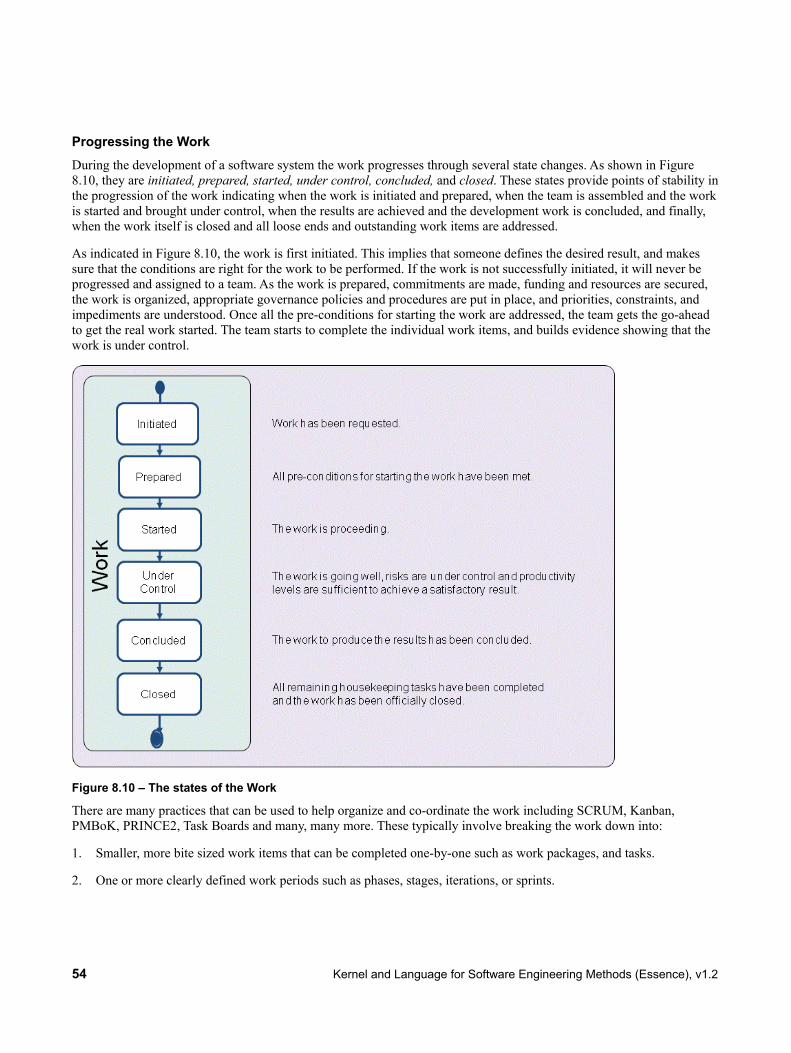
54 Kernel and Language for Software Engineering Methods (Essence), v1.2
Progressing the Work During the development of a software system the work progresses through several state changes. As shown in Figure 8.10, they are initiated, prepared, started, under control, concluded, and closed. These states provide points of stability in the progression of the work indicating when the work is initiated and prepared, when the team is assembled and the work is started and brought under control, when the results are achieved and the development work is concluded, and finally, when the work itself is closed and all loose ends and outstanding work items are addressed.
As indicated in Figure 8.10, the work is first initiated. This implies that someone defines the desired result, and makes sure that the conditions are right for the work to be performed. If the work is not successfully initiated, it will never be progressed and assigned to a team. As the work is prepared, commitments are made, funding and resources are secured, the work is organized, appropriate governance policies and procedures are put in place, and priorities, constraints, and impediments are understood. Once all the pre-conditions for starting the work are addressed, the team gets the go-ahead to get the real work started. The team starts to complete the individual work items, and builds evidence showing that the work is under control.
Figure 8.10 – The states of the Work
There are many practices that can be used to help organize and co-ordinate the work including SCRUM, Kanban, PMBoK, PRINCE2, Task Boards and many, many more. These typically involve breaking the work down into:
1. Smaller, more bite sized work items that can be completed one-by-one such as work packages, and tasks.
2. One or more clearly defined work periods such as phases, stages, iterations, or sprints.

Kernel and Language for Software Engineering Methods (Essence), v1.2 55
The level, depth and extent of the work breakdown depends on the style and complexity of the work and on the specific practices the team selects to help them co-ordinate, monitor, control, and undertake the work.
If the team has their work under control then there will be concrete evidence that:
1. The work is going well.
2. The risks threatening a successful conclusion to the work are under control as the impact if they occur and/or as the likelihood of them occurring have been reduced to acceptable levels.
3. The team’s productivity levels are sufficient to achieve satisfactory results within the time, budget and any other constraints that have been placed upon the work.
Typically, once the work has been concluded and the results have been accepted by the relevant stakeholders, there remain some final housekeeping and wrap up activities to be completed before the work itself can be closed.
If, for any reason, the work is not going well, then it may be halted, abandoned or reverted to a previous state. If the work is abandoned once it is started, it should still be properly closed even though it has not managed to pass through the concluded state.
Understanding the current and desired state of the work can help the team to balance their activities, make the correct investment decisions, nurture the work that is going well, and help or cancel the work that is going badly.
Checking the Progress of the Work To help assess the state of the work and the progress being made towards its successful conclusion, the following checklists are provided.
Table 8.7 – Checklist for Work State Checklist
Initiated The result required of the work being initiated is clear.
Any constraints on the work’s performance are clearly identified.
The stakeholders that will fund the work are known.
The initiator of the work is clearly identified.
The stakeholders that will accept the results are known.
The source of funding is clear.
The priority of the work is clear.

56 Kernel and Language for Software Engineering Methods (Essence), v1.2
State Checklist
Prepared Commitment is made.
Cost and effort of the work are estimated.
Resource availability is understood.
Governance policies and procedures are clear.
Risk exposure is understood.
Acceptance criteria are defined and agreed with client.
The work is broken down sufficiently for productive work to start.
Tasks have been identified and prioritized by the team and stakeholders.
A credible plan is in place.
Funding to start the work is in place.
The team or at least some of the team members are ready to start the work.
Integration and delivery points are defined. Started Development work has been started.
Work progress is monitored.
The work is being broken down into actionable work items with clear definitions of done.
Team members are accepting and progressing tasks. Under Control Tasks are being completed.
Unplanned work is under control.
Risks are under control as the impact if they occur and the likelihood of them occurring have been reduced to acceptable levels.
Estimates are revised to reflect the team’s performance.
Measures are available to show progress and velocity.
Re-work is under control.
Tasks are consistently completed on time and within their estimates. Concluded All outstanding tasks are administrative housekeeping or related to preparing the next
piece of work.
Work results have been achieved.
The stakeholder(s) has accepted the resulting software system.

Kernel and Language for Software Engineering Methods (Essence), v1.2 57
State Checklist
Closed Lessons learned have been itemized, recorded and discussed.
Metrics have been made available.
Everything has been archived.
The budget has been reconciled and closed.
The team has been released.
There are no outstanding, uncompleted tasks.
8.4.2.3 Way-of-Working
Description Way-of-Working: The tailored set of practices and tools used by a team to guide and support their work.
The team evolves their way of working alongside their understanding of their mission and their working environment. As their work proceeds they continually reflect on their way of working and adapt it to their current context, if necessary.
States Principles Established The principles, and constraints, that shape the way-of-working are
established. Foundation Established The key practices, and tools, that form the foundation of the way of
working are selected and ready for use. In Use Some members of the team are using, and adapting, the way-of-
working. In Place All team members are using the way of working to accomplish their
work. Working well The team's way of working is working well for the team. Retired The way of working is no longer in use by the team.
Associations
guides : Work Way-of-Working guides Work.
Justification: Why Way-of-Working?
Software engineering is a team sport, one that requires the whole team to collaborate effectively regardless of how the team is organized. They need to agree on a way of working that will support collaboration and guide them throughout the software engineering endeavor.
The way of working:
• Is key to enabling a team to work together effectively.
• Focuses the team on how they will collaborate to ensure success.
• Enables the work to be planned and controlled.

58 Kernel and Language for Software Engineering Methods (Essence), v1.2
• Helps the team, and their associated stakeholders, to successfully fulfill their responsibilities.
Figure 8.11 – The states of the Way-of-Working
Progressing the Way-of-Working During the course of a software engineering endeavor the way of working progresses through several state changes. As presented in Figure 8.11, they are principles established, foundation established, in use, in place, working well, and retired. These states focus on the way a team establishes an effective way-of-working indicating:
1. When the principles and constraints that shape the way-of-working are established.
2. When a minimal number of key practices and tools have been identified and integrated to establish a foundation for the evolution of the team’s way-of-working.
3. When the chosen way of working is in use by the team.
4. When a team’s way of working is in place and in use by the whole team.
5. When it is working well.
6. When the way of working has been retired and is no longer in use by the team.
Examples of principles and constraints could be how far into the future you plan, governance policies, how decisions are made, and how the work in broken down.

Kernel and Language for Software Engineering Methods (Essence), v1.2 59
There are many ways of working that the team could adopt to meet their objectives and establish their approach to software engineering. As shown in Figure 8.11, the first step in adopting a new way-of-working, or adapting an existing way-of-working, is to understand the team’s working environment and establish the principles that will guide their selection of appropriate practices and tools. This includes identifying the constraints governing the selection of the team's practices and tools and understanding the practices and tools that the team, and their stakeholders, are already using or are required to use.
It is not enough to just understand the principles and constraints that will inform the team's way of working. These must be agreed with, and actively supported by, the team and its stakeholders. Once the principles are established the team is ready to start selecting the practices and tools that will form their way-of-working.
To establish a natural way of working the focus should first be on the key practices and tools; those that bring the team together, enable communication among the team members, support collaborative working and are essential to the success of the team. However, these practices and tools act as the foundation for the team’s way-of-working. Before the foundation can be assembled it is important to understand the gaps between the practices and tools needed by the team and the practices, and tools immediately available to the team. This enables the activities needed to fill these gaps to be planned.
Once the key practices and tools are integrated then the way-of-working’s foundation is established and the way-of-working is ready to be trialed by the team. It will however be continuously adapted as the work progresses, and additional practices and tools will be added as the team inspects their way-of-working and adapts it to meet their changing circumstances.
Rather than spending more time tailoring or tuning the way-of-working it is important that the team puts it into use as soon as possible. The way-of-working is in use as soon as any of the team members are using and adapting it as part of completing their work. As more and more of the team start to use and benefit from the way-of-working its usage will grow until it is firmly in place and all the team members are using it to accomplish their work. Some team members may still need help to understand certain aspects of the team's way of working and to make effective progress, but the way of working is now the normal way for the team to develop software.
As the team progresses through the work, the way of working will become embedded in their activities and collaborations to such an extent that its use, inspection and adaptation are all seen as a natural part of the way the team works. The way-of-working is working well once it has stabilized and all team members are making progress as planned by using and adapting it to suit their current working environment. Finally, when the way of working is no longer in use by the team, it is retired.
Understanding the current and desired state of the team's way of working helps a team to continually improve their performance, and adapt quickly and effectively to change.
Checking the Progress of the Way-of-Working To help assess the current status of the way of working, the following checklists are provided.

60 Kernel and Language for Software Engineering Methods (Essence), v1.2
Table 8.8 – Checklist for Way-of-Working State Checklist
Principles Established Principles and constraints are committed to by the team.
Principles and constraints are agreed to by the stakeholders.
The tool needs of the work and its stakeholders are agreed.
A recommendation for the approach to be taken is available.
The context within which the team will operate is understood.
The constraints that apply to the selection, acquisition, and use of practices and tools are known.
Foundation Established
The key practices and tools that form the foundation of the way-of-working are selected.
Enough practices for work to start are agreed to by the team.
All non-negotiable practices and tools have been identified.
The gaps that exist between the practices and tools that are needed and the practices and tools that are available have been analyzed and understood.
The capability gaps that exist between what is needed to execute the desired way of working and the capability levels of the team have been analyzed and understood.
The selected practices and tools have been integrated to form a usable way-of-working. In Use The practices and tools are being used to do real work.
The use of the practices and tools selected are regularly inspected.
The practices and tools are being adapted to the team’s context.
The use of the practices and tools is supported by the team.
Procedures are in place to handle feedback on the team’s way of working.
The practices and tools support team communication and collaboration. In Place The practices and tools are being used by the whole team to perform their work.
All team members have access to the practices and tools required to do their work.
The whole team is involved in the inspection and adaptation of the way-of-working. Working well Team members are making progress as planned by using and adapting the way-of-
working to suit their current context.
The team naturally applies the practices without thinking about them.
The tools naturally support the way that the team works.
The team continually tunes their use of the practices and tools.

Kernel and Language for Software Engineering Methods (Essence), v1.2 61
State Checklist
Retired The team's way of working is no longer being used.
Lessons learned are shared for future use.
8.4.3 Activity Spaces
The endeavor area of concern contains five activity spaces that cover the formation and support of the team, and planning and co-coordinating the work in-line with the way of working.
8.4.3.1 Prepare to do the Work
Description Set up the team and its working environment. Understand and commit to completing the work.
Prepare to do the work to:
• Put the initial plans in place.
• Establish the initial way of working.
• Assemble and motivate the initial project team.
• Secure funding and resources.
Input: Stakeholders, Opportunity, Requirements
Entry Criteria: None
Completion Criteria: Team::Seeded, Way of Working::Foundation Established, Work::Prepared
8.4.3.2 Coordinate Activity
Description Co-ordinate and direct the team’s work. This includes all ongoing planning and re-planning of the work, and adding any additional resources needed to complete the formation of the team.
Coordinate activity to:
• Select and prioritize work.
• Adapt plans to reflect results.
• Get the right people on the team.
• Ensure that objectives are met.
• Handle change.
Input: Requirements, Team, Work, Way of Working

62 Kernel and Language for Software Engineering Methods (Essence), v1.2
Entry Criteria: Team::Seeded, Work::Prepared
Completion Criteria: Team::Formed, Work::Under Control
8.4.3.3 Support the Team
Description Help the team members to help themselves, collaborate, and improve their way of working.
Support the team to:
• Improve team working.
• Overcome any obstacles.
• Improve ways of working.
Input: Team, Work, Way of Working
Entry Criteria: Team::Formed, Way of Working::Foundation Established
Completion Criteria: Team::Collaborating, Way of Working::In Place
8.4.3.4 Track Progress
Description Measure and assess the progress made by the team.
Track progress to:
• Evaluate the results of work done.
• Measure progress.
• Identify impediments.
Input: Requirements, Team, Work, Way of Working
Entry Criteria: Team::Collaborating, Way of Working::In Place, Work::Started
Completion Criteria: Team::Performing, Way of Working::Working Well, Work::Concluded
8.4.3.5 Stop the Work
Description Shutdown the software engineering endeavor and hand over the team’s responsibilities.
Stop the work to:
• Close the work.
• Hand over any outstanding responsibilities.

Kernel and Language for Software Engineering Methods (Essence), v1.2 63
• Hand over any outstanding work items.
• Stand down the team.
• Archive all work done.
Input: Requirements, Team, Work, Way of Working
Entry Criteria: Team::Performing, Way of Working::Working Well, Work::Concluded
Completion Criteria: Team::Adjourned, Way of Working::Retired, Work::Closed
8.4.4 Competencies
8.4.4.1 Leadership
Description This competency enables a person to inspire and motivate a group of people to achieve a successful conclusion to their work and to meet their objectives.
People with the leadership competency help the team to:
• Inspire people to do their work.
• Make sure that all team members are effective in their assignments.
• Make and meet their commitments.
• Resolve any impediments or issues holding up the team's work.
• Interact with stakeholders to shape priorities, report progress, and respond to challenges.
Essential skills include:
• Inspiration
• Motivation
• Negotiation
• Communication
• Decision making
This competency is sometimes provided by a Scrum Master, an appointed team leader, the more experienced members of the team, or a dedicated project manager.
Competency Levels Level 1 – Assists Demonstrates a basic understanding of the concepts and can follow instructions. Level 2 – Applies Able to apply the concepts in simple contexts by routinely applying the experience
gained so far. Level 3 – Masters Able to apply the concepts in most contexts and has the experience to work without
supervision.

64 Kernel and Language for Software Engineering Methods (Essence), v1.2
Level 4 – Adapts Able to apply judgment on when and how to apply the concepts to more complex contexts. Can enable others to apply the concepts.
Level 5 - Innovates A recognized expert, able to extend the concepts to new contexts and inspire others.
Justification: Why Leadership? Software engineering is a complex endeavor typically involving teams of people dedicated to delivering an appropriate solution to extended networks of customers, users, and other stakeholders. It is essential that everybody is focused, inspired, and motivated towards achieving the same goals.
Within the software engineering kernel, the leadership competency is the ability to radiate enthusiasm, energy, trustworthiness, confidentiality, and direction. The people with this competency guide and help the team to a successful conclusion, one that satisfies the needs of the stakeholders, within acceptable time and cost constraints.
8.4.4.2 Management
Description This competency encapsulates the ability to coordinate, plan, and track the work done by a team.
The management competency is the administrative and organizational ability that enables the right things to be done at the right time to maximize a team’s chances of success.
Management helps the team to:
• Proactively manage risks
• Account for time and money spent
• Interact with stakeholders to report progress
• Coordinate and plan activities
Essential skills include:
• Communication
• Administration
• Organization
• Resource planning
• Financial reporting
This competency can be provided by the team members themselves, a team leader, a lead developer, a project manage-ment office or a professional project manager.
Competency Levels Level 1 – Assists Demonstrates a basic understanding of the concepts and can follow instructions. Level 2 – Applies Able to apply the concepts in simple contexts by routinely applying the experience
gained so far. Level 3 – Masters Able to apply the concepts in most contexts and has the experience to work without
supervision.

Kernel and Language for Software Engineering Methods (Essence), v1.2 65
Level 4 – Adapts Able to apply judgment on when and how to apply the concepts to more complex contexts. Can enable others to apply the concepts.
Level 5 - Innovates A recognized expert, able to extend the concepts to new contexts and inspire others.
Justification: Why Management? Software engineering is a complex endeavor that requires the organization and coordination of many people and other resources. It needs the team to possess the ability to track progress, organize facilities and events, co-ordinate all the work, and integrate into the structure of the owning organization. The management competency encapsulates the abilities needed to be able to coordinate and track the work done by the team.

66 Kernel and Language for Software Engineering Methods (Essence), v1.2
This page intentionally left blank.

Kernel and Language for Software Engineering Methods (Essence), v1.2 67
9 Language Specification
9.1 Specification Technique This specification is constructed using a combination of three different techniques: a metamodel, a formal language, and natural language. The metamodel (see 9.2) expresses the abstract syntax and some constraints on the structural relationships between the elements. An invariant is provided for each element that, together with the structural constraints in the metamodel, provides the well-formedness rules of the language (the static semantics). The invariants and some additional operations are stated using the Object Constraint Language (OCL) as the formal language used in this document. The composition of elements (see 9.4) as well as the dynamic semantics (see 9.5) are described using natural language (English) accompanied by formal definitions using Vienna Development Method where appropriate.
9.1.1 Different Meta-Levels
The metamodel is based upon a standard specification technique using four meta-levels of constructs (meta-classes). These levels are:
• Level 3 – Meta-Language: the specification language, i.e., the different constructs used for expressing this specification, like “meta-class” and “binary directed relationship.”
• Level 2 – Construct: the language constructs, i.e., the different types of constructs expressed in this specification, like “Alpha” and “Activity.”
• Level 1 – Type: the specification elements, i.e., the elements expressed in specific kernels and practices, like “Requirements” and “Find Actors and Use Cases.”
• Level 0 – Occurrence: the run-time instances, i.e., these are the representations of real-life elements in a running development effort.
For a more thorough description of the meta-level hierarchy, see Sections 7.9-7.11 in UML Infrastructure [UML 2011].
9.1.2 Specification Format
Within each subclause, there is first a brief informal description of the purpose of the elements in that language layer. This is followed by a description of the abstract syntax of these elements together with some of the well-formedness rules, i.e., the multiplicity of the associated elements. The abstract syntax is defined by a CMOF model [MOF 2011], the same language used to define the UML metamodel. Each modeling construct is represented by an instance of a MOF class or association. In this specification, this model is described by a set of UML class and package diagrams showing the language elements and their relationships.
Following the abstract syntax is an enumeration of the elements in alphabetic order. Each concept is described according to:
• Heading is the formal name of the language element.
• Description is a short informal description of the element. This is intended as a quick reference for those who want only the basic information about an element.

68 Kernel and Language for Software Engineering Methods (Essence), v1.2
• Generalizations list each of the parents (superclasses) of the language element, i.e., all elements it has generalizations to.
• Attributes lists each of the attributes that are defined for that element. Each attribute is specified by its formal name, its type, and multiplicity. This is followed by a textual description of the purpose and meaning of the attribute. The following data types for attributes are used:
o String
o Boolean
o Integer
o GraphicalElement
If data type Integer is used for lower or upper bounds on classes representing associations, only positive values, 0, and -1 are allowed. As by the usual convention, -1 represents an unlimited bound in these cases.
• Associations list all the association ends owned by the element. Note that this subclause does not list the association-owned association ends. The format for element-owned association ends is the same as the one for attributes described above.
• Invariant describes the well-formedness rules for the element. These are mostly described both with an informal text and with OCL expressions.
• Additional Operations describes any additional operations needed when expressing the well-formedness rules. These are mostly described both with an informal text and with OCL expressions. This subclause is only present when there are any additional operations defined.
• Semantics provides a detailed description of the element in natural language.
9.1.3 Notation Used
The following conventions are adopted in the diagrams throughout the specification:
• All meta-class names and class names start with an uppercase letter.
• An association with one end marked by a navigability arrow means that the association is navigable in the direction of that end. An association end marked with a dot is owned by the element on the opposite end. An association end not marked with a dot is owned by the association itself.
9.2 Conceptual Overview of the Language This subclause serves as a narrative introduction to the most important language elements and illustrates their semantics on a coarse-grained level.
Figure 9.1 illustrates informally the main elements of the language and their most important associations. The elements centered in the figure (i.e., Alpha, Alpha State, Activity Space, and Competency) are used to describe the contents of a Kernel. They provide the abstract and essential things to do, things to work with, and things to know in software engineering endeavors. It is considered sufficient to know these four elements to be able to talk about the state, progress, and health of a software engineering endeavor.

Kernel and Language for Software Engineering Methods (Essence), v1.2 69
While the elements used in a Kernel represent abstract things, concrete guidance can be created via Practices by adding elements like those shown on the right hand side of the figure. Work Products represent the concrete things to work with, providing evidence for the states an Alpha is in. For example, the source code provides evidence on whether a component is fully implemented or just a stub. Activities provide explicit guidance on how to produce or update Work Products, which eventually will lead to state changes on some Alpha.
The dynamic semantics of the language are concerned with Alpha States and Activities. Based on the States an endeavor is in and based on the States a team wants to reach next, Activities are derived that drive the endeavor towards that goal.
Figure 9.1 – Conceptual Overview of the Language
Patterns and Resources are generic concepts that can be attached to any language element. They are not considered by the dynamic semantics of the language as defined in this specification. Examples for Resources include templates attached to Work Products, scripts or tools attached to Activities, and learning materials or tests attached to Competencies. A simple and usual way to tailor or adapt predefined Practices is to add specialized resources or replace existing ones.
Patterns can arrange language elements into arbitrary meaningful structures. Examples for Patterns are shown in Figure 9.2. There is no limitation in the number of elements involved in a pattern. Patterns may also relate to other Patterns, like a Pattern for phases, which sequence Activities or Activity Spaces and end by reaching a milestone, which in turn is a Pattern again that aligns a set of Alpha States in order to synchronize the progress of Alphas.
Beyond these main elements, the language contains additional elements to detail the associations and to handle metadata.
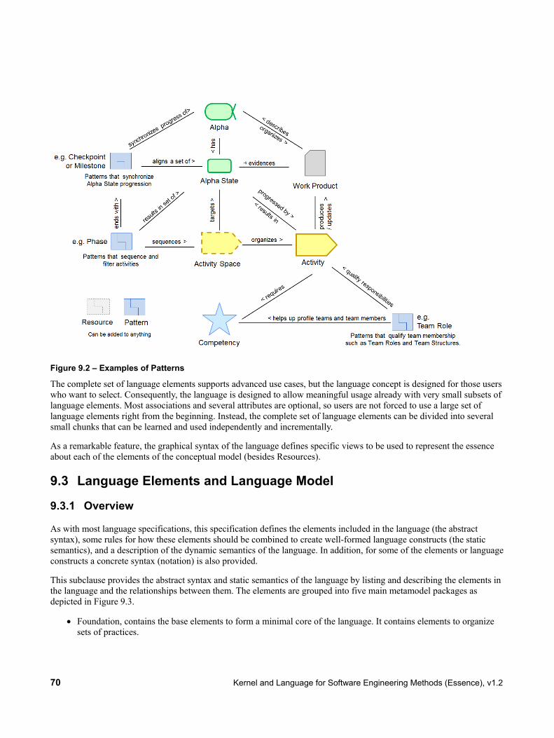
70 Kernel and Language for Software Engineering Methods (Essence), v1.2
Figure 9.2 – Examples of Patterns
The complete set of language elements supports advanced use cases, but the language concept is designed for those users who want to select. Consequently, the language is designed to allow meaningful usage already with very small subsets of language elements. Most associations and several attributes are optional, so users are not forced to use a large set of language elements right from the beginning. Instead, the complete set of language elements can be divided into several small chunks that can be learned and used independently and incrementally.
As a remarkable feature, the graphical syntax of the language defines specific views to be used to represent the essence about each of the elements of the conceptual model (besides Resources).
9.3 Language Elements and Language Model
9.3.1 Overview
As with most language specifications, this specification defines the elements included in the language (the abstract syntax), some rules for how these elements should be combined to create well-formed language constructs (the static semantics), and a description of the dynamic semantics of the language. In addition, for some of the elements or language constructs a concrete syntax (notation) is also provided.
This subclause provides the abstract syntax and static semantics of the language by listing and describing the elements in the language and the relationships between them. The elements are grouped into five main metamodel packages as depicted in Figure 9.3.
• Foundation, contains the base elements to form a minimal core of the language. It contains elements to organize sets of practices.

Kernel and Language for Software Engineering Methods (Essence), v1.2 71
• AlphaAndWorkProduct, contains the base elements to form minimal practices. A domain model for software engineering endeavors can be created. No activities can be expressed using this layer, but concrete work products can be related to abstract domain elements.
• ActivitySpaceAndActivity, contains elements to enrich practices by expressing activities.
• Competency, contains elements to support the specification of competencies.
• UserDefinedTypes, contains elements to enrich simple elements from Foundation with type information.
• View, contains elements to support the specification of view contents.
The dependency between the packages is expressed with import relationships. Each of the packages is described in a separate subclause.
Figure 9.3 – Structure of the Essence Language metamodel
9.3.2 Foundation
9.3.2.1 Overview The intention of the Foundation package is to provide all the base elements, including abstract super classes, necessary to form a baseline foundation for the Language. The elements and their relationships are presented in the diagrams below. A detailed definition of each of the elements is found in the following subclauses.

72 Kernel and Language for Software Engineering Methods (Essence), v1.2
Figure 9.4 – Foundation::Language element super class
Figure 9.5 – Foundation::Language elements

Kernel and Language for Software Engineering Methods (Essence), v1.2 73
Figure 9.6 – Foundation::Containers
Figure 9.7 – Foundation::Generic elements
9.3.2.2 BasicElement Package: Foundation isAbstract: Yes Generalizations: LanguageElement
Description Abstract superclass for all main concepts in Essence other than Element groups.

74 Kernel and Language for Software Engineering Methods (Essence), v1.2
Attributes name : String [1] The name of the element. icon : GraphicalElement [0..1] The icon to be used when presenting the element. briefDescription : String [1] A short and concise description of what the element is. It is
discouraged to use rich formatting and structuring elements like section headings in the brief description. The content of this attribute should be a summary of the content given in attribute “description”.
description : String [1] A more detailed description of the element. The content of this attribute may be written in a markup language to allow for rich descriptions. It may include section headings, formatting information, hyperlinks, or similar to ease structured reading and navigation.
Associations N/A
Invariant true
Semantics Basic elements are considered to represent the small set of main concepts within Essence. Basic elements are most likely the first elements of Essence a user interacts with.
Elements of Essence which are no basic elements (and no element groups) are considered to be auxiliary elements used to detail or connect basic elements.
9.3.2.3 Checkpoint Package: Foundation isAbstract: No Generalizations: “LanguageElement”
Description A condition that can be tested as true or false that contributes to the determination of whether a state (of an alpha), or a level of detail (of a work product), or a competency level has been attained.
Attribute name : String [1] The name of the checkpoint. description : String [1] shortDescription : String [0..1]
A description of the checkpoint. An optional abbreviated version of the full description.
Associations N/A
Invariant true

Kernel and Language for Software Engineering Methods (Essence), v1.2 75
Semantics Checkpoints are used as follows:
• The checkpoints of an alpha state are joined by AND. The state of an alpha is deemed to be the most advanced (favorable) state for which all checkpoints are true.
• The checkpoints of a work product level of detail are joined by OR. The level of detail of a work product is deemed to be the most detailed level for which at least one checkpoint is true.
9.3.2.4 ElementGroup Package: Foundation isAbstract: Yes Generalizations: "LanguageElement"
Description A generic name for an Essence concept that names a collection of elements. Element groups are recursive, so a group may own other groups, as well as other (non-group) elements.
Attributes name : String [1] The name of the element group. icon : GraphicalElement [0..1] The icon to be used when presenting the element group. briefDescription : String [1] A short description of what the group is. It is discouraged to use rich
formatting and structuring elements like section headings in the brief description. The content of this attribute should be a summary of the content given in attribute “description”.
description : String [1] A more detailed description of the group. The content of this attribute may be written in a markup language to allow for rich descriptions. It may include section headings, formatting information, hyperlinks, or similar to ease structured reading and navigation.
Associations referredElements : LanguageElement [0..*] The language elements this group owns by reference. ownedElements : LanguageElement [0..*] The language elements this group owns by value.
Invariant -- An element group may not own itself self.allElements(ElementGroup)->excludes(self) -- An element group may only extend elements it owns self.extensions->forAll(e | self.allElements(e.targetElement.oclType()) ->includes(e.targetElement))
Additional Operations -- Get all elements of a particular type which are available within this group and its referenced groups. context ElementGroup::allElements (t : OclType) : Set(t)

76 Kernel and Language for Software Engineering Methods (Essence), v1.2
body: self.referredElements->select(e | e.oclIsKindOf(t)) ->union(self.allElements(ElementGroup)->collect(c | c.allElements(t)) ->union(self.ownedElements->select(e | e.oclIsKindOf(t)))
Semantics Element groups are used to organize Essence elements into meaningful collections such as Kernels or Practices. Elements in a particular group belong together for some reason, while elements outside that group do not belong to them. The reasoning for including elements in the group should be given in the description attribute of the group.
Element groups can own their members by reference or by value.
If an element group owns two or more members of the same type and name, composition (cf. 9.4) is applied to them so that only one merged element of that type with that name is visible when viewing the contents of the element group.
9.3.2.5 EndeavorAssociation Package: Foundation isAbstract: No Generalizations:
Description Represents associations that you want to track during an endeavor.
Attributes N/A
Associations memberEnd: EndeavorProperty [2..*] End properties of the association. ownedEnd: EndeavorProperty [*] The properties of this association.
Invariant true
Semantics Endeavor associations are used to link actual instances of elements on metalevel 0 (aka “the endeavor level”). This can be used for instance to keep track of which particular document (an instance of a work product) was created by which particular team member (an instance of alpha “Team member”). In general, these associations have no specific semantics within Essence.
9.3.2.6 EndeavorProperty Package: Foundation isAbstract: No Generalizations:

Kernel and Language for Software Engineering Methods (Essence), v1.2 77
Description An element to represent properties that you want to track during an endeavor; each property can either be simple or be expressed via an association.
Attributes name: String [1] Name of the property. lowerBound: Integer [1] Lower bound of the property. upperBound : Integer [1] Upper bound of the property.
Associations association : EndeavorAssociation [0..1]
The association used to express this property if it is not a simple property.
owningAssociation : EndeavorAssociation [0..1]
The association owning this property.
type : Type [1] The type of the property.
Invariant true
Semantics Endeavor properties are used to track individual properties of actual instances of elements during an endeavor. Endeavor properties can be defined individually for language elements. See 9.5 for the minimal set of endeavor properties that is used by the dynamic semantics of Essence.
9.3.2.7 ExtensionElement Package: Foundation isAbstract: No Generalizations: "LanguageElement"
Description An element that extends a language element by replacing the content of one of its attributes.
Attributes targetAttribute : String [1] The name of the attribute which is to be extended. extensionFunction : String [1] The function applied to the target attribute.
Associations targetElement : LanguageElement [1] The element to be extended.
Invariant -- The target element may not be an extension element or merge resolution not self.targetElement.oclIsKindOf(ExtensionElement) and not self.targetElement.oclIsKindOf(MergeResolution)

78 Kernel and Language for Software Engineering Methods (Essence), v1.2
Semantics If an extension X is associated with a target element T and referenced by element group C, then when T is viewed in C, what is seen is T modified by X by applying extension functions to the attributes of T. See 9.4 for the detailed mechanism.
9.3.2.8 Kernel Package: Foundation isAbstract: No Generalizations: "ElementGroup"
Description A kernel is a set of elements used to form a common ground for describing a software engineering endeavor. A kernel is an element group that names the basic concepts (i.e., alphas, activity spaces and competencies) for a domain (e.g., Software Engineering).
Attributes consistencyRules : String [1] A set of rules on the consistency of a particular Kernel. The format for
writing these rules is out of the scope of this specification. It is recommended to use either plain text or OCL.
Associations N/A
Invariant -- A kernel can only contain alphas, alpha associations, alpha containments, activity spaces, competencies, kernels, extension elements, and merge resolutions. self.referredElements->union(self.ownedElements)->forAll (e | e.oclIsKindOf(Alpha) or e.oclIsKindOf(AlphaAssociation) or e.oclIsKindOf(AlphaContainment) or e.oclIsKindOf(ActivitySpace) or e.oclIsKindOf(Competency) or e.oclIsKindOf(Kernel) or e.oclIsKindOf(ExtensionElement) or e.oclIsKindOf(MergeResolution)) -- The alphas associated by alpha associations are available within the kernel or -- its referred kernels. self.allElements(AlphaAssociation)->forAll (aa | self.allElements(Alpha) ->includes (aa.end1) and self.allElements(Alpha)->includes (aa.end2)) -- All input alphas of the activity spaces are available within the -- kernel or its referred kernels. self.allElements(ActivitySpace)->forAll (as | self.allElements(Alpha) ->includesAll(as.input)) -- Completion criteria are only expressed in terms of states which belong to alphas which are available in the kernel or its referred kernels. self.allElements(ActivitySpace)->forAll (as | as.completionCriterion->forAll (cc | cc.state<> null and cc.workProduct = null and self.allElements(Alpha)->exists(a | a.states->includes(cc.state))))

Kernel and Language for Software Engineering Methods (Essence), v1.2 79
Semantics A kernel is a kind of domain model. It defines important concepts that are general to everyone when working in that domain, like software engineering development.
A kernel may be defined including references to other kernels. For example, a more basic kernel may contain elements that are meaningful to the domain of “Software Engineering” and that may be used in the specific context of “Software Engineering for safety critical” domains as defined by a referring kernel.
A kernel is closed in that elements in the kernel may only refer to elements which are also part of the kernel or it’s referred kernels.
9.3.2.9 LanguageElement Package: Foundation isAbstract: Yes Generalizations:
Description Abstract superclass for an Essence concept.
Attributes isSuppressable : Boolean A flag indicating whether this element may be suppressed in an
extension or composition (see 9.4.3.2).
Associations owner : ElementGroup [0..1] The element group that owns this language element. tags : Tag [0..*] Tags associated with this language element. resources : Resource[0..*] Resources associated with this language element. properties : EndeavorProperty [*] Properties (defined at M1 level) that you want to track during the
endeavor.
Invariant -- All language elements that are not element groups need an owner (not self.oclIsKindOf(ElementGroup)) implies owner <> null -- Each and every instance of LanguageElement may be related to each other via endeavor associations LanguageElement::allInstances->forAll(e1,e2 : LanguageElement | EndeavorAssociation::allInstances->exists(a: EndeavorAssociation | a.memberEnd ->exists(p1,p2 : EndeavorProperty | p1.languageElement=e1 and p2.languageElement=e2)))
Semantics Language element is the root for all basic elements, auxiliary elements and element groups. It defines the concepts within the Essence language that can be grouped to build composite entities such as Kernels and Practices.

80 Kernel and Language for Software Engineering Methods (Essence), v1.2
9.3.2.10 Library Package: Foundation isAbstract: No Generalizations: "ElementGroup"
Description A library is a container that names a collection of element groups.
Attributes N/A
Associations N/A
Invariant -- A library may only own element groups self.referredElements->forAll(e | e.oclIsKindOf(ElementGroup)) and self.ownedElements->forAll(e | e.oclIsKindOf(ElementGroup))
Semantics A library contains element groups relevant for a specific subject or area of knowledge, like software development.
A library can be used to set up a meaningful collection of element groups of any scale, e.g., a collection of practices used in a company or a collection of practices and kernels taught in a university course.
9.3.2.11 MergeResolution Package: Foundation isAbstract: No Generalizations: "LanguageElement"
Description An element that provides a solution for a merge conflict as defined in 9.4.4.3.
Attributes targetAttribute : String [1] The name of the attribute on which the conflict is solved. targetName : String [1] The name of the element on which the conflict is solved. resolutionFunction : String [1] The function applied to the target attribute.
Associations N/A
Invariant true
Kernel and Language for Software Engineering Methods (Essence), v1.2 81
Semantics If an element group refers to more than one element with the same name, these elements are merged when viewing the content of this element group. For each conflicting attribute on the merged objects, a merge resolution must be defined. It applies a resolution function to the conflicting attributes and returns the attribute value to be used as resolution. See 9.4 for the detailed mechanism.
9.3.2.12 Method Package: Foundation isAbstract: No Generalizations: "ElementGroup"
Description A Method is the composition of a Kernel and a set of Practices to fulfill a specific purpose.
Attributes purpose : String [1] The purpose of this Method. The content of this attribute should be
an explicit short statement that describes the goal that the method pursues. Additional explanations can be given in the attribute “description” inherited from “ElementGroup”.
Associations baseKernel : Kernel [1] The Kernel this Method is based on.
Invariant -- A method can only contain practices. self.referredElements->forAll (e | e.oclIsKindOf(Practice)) and self.ownedElements->forAll (e | e.oclIsKindOf(Practice))
Semantics A method contains a set of practices to express the practitioners’ way of working in order to fulfill a specific purpose. The method purpose should consider the stakeholder needs, particular conditions, and the desired software product. The set of practices that makes up a method should contribute and be sufficient to the achievement of this purpose.
For example, a method purpose can be related to developing, maintaining, or integrating a software product.
The set of practices, that articulate a method, should satisfy the coherence, consistency, and completeness properties. The set of practices is coherent if the objective of each practice contributes to the entire method purpose, is consistent if each of its entries and results are interrelated and useful. Finally, it is complete if the achievement of all practice objectives fulfills entirely the method purpose and produces expected output.
Those properties are most likely not true from the beginning while authoring a method.
9.3.2.13 Pattern Package: Foundation isAbstract: No Generalizations: "BasicElement"

82 Kernel and Language for Software Engineering Methods (Essence), v1.2
Description A pattern is a generic mechanism for naming complex concepts that are made up of several Essence elements. A pattern is defined in terms of pattern associations.
Attributes N/A
Associations associations : PatternAssociation [*] Named association types between elements.
Invariant true
Semantics Pattern is a general mechanism for defining a structure of language elements. Typically, the pattern references other elements in a practice or kernel. For example, a role may be defined by referencing required competencies, having responsibility of work products, and participation in activities. Another example could be a phase which groups activity spaces that should be performed during that phase.
Patterns can also be used to model complex conditions. For example, a pattern for pre-conditions can create associations to activities, work products and level of detail to express that particular work products must be present in at least the designated levels of detail to be ready to start the particular activities.
9.3.2.14 PatternAssociation Package: Foundation isAbstract: No Generalizations: "LanguageElement"
Description Pattern associations are used to create named links between the elements of a pattern.
Attributes name : String [1] Name of the association.
Associations elements : LanguageElement [*] The elements taking part in the pattern via this association.
Invariant -- A pattern association may not refer to other pattern associations, element groups, extension elements, or merge resolutions self.elements->forAll (e | not e.oclIsKindOf(PatternAssocation) and not e.oclIsKindOf(ElementGroup) and not e.oclIsKindOf(ExtensionElement) and not e.oclIsKindOf(MergeResolution))

Kernel and Language for Software Engineering Methods (Essence), v1.2 83
Semantics Each pattern association introduces elements to take part in a pattern. The name of the pattern association should explain the meaning these elements have inside the pattern. For example, in a pattern defining a toolset there may be a pattern association named “used for” referring to an activity, another pattern association named “used on” referring to a work product, and a third pattern association named “suitable for” referring to a level of detail on the work product that can be achieved with that toolset.
9.3.2.15 Practice Package: Foundation isAbstract: No Generalizations: "ElementGroup"
Description A practice is a repeatable approach to doing something with a specific objective in mind. A practice describes how to handle a specific aspect of a software engineering endeavor, including the descriptions of all relevant elements necessary to express the desired work guidance that is required to achieve the purpose of the practice. A practice can be defined as a composition of other practices.
Attributes consistencyRules : String [1] Rules on the consistency of a particular Practice. The format for
writing these rules is out of the scope of this specification. It is recommended to use either plain text or OCL.
objective : String [1] The objective of this Practice, expressed as a concise and isolated phrase. The content of this attribute should be an explicit and short statement that describes the goal that the practice pursues. Additional explanations can be given in the attribute “description” inherited from “ElementGroup”.
measures : String [0..*] List of standard units used to evaluate the practice performance and the objectives’ achievement.
entry : String [0..*] Expected characteristics of elements needed to start the execution of a practice.
result: String [0..*] Expected characteristics of elements required as outputs after the execution a practice is completed.
Associations N/A
Invariant -- The alphas and the work products associated by the work product manifests are -- visible within the practice. self.allElements(WorkProductManifest)->forAll (wpm | self.allElements(Alpha)->includes (wpm.alpha) and self.allElements(WorkProduct)->includes (wpm.workProduct) -- Associated activities are visible within the practice.

84 Kernel and Language for Software Engineering Methods (Essence), v1.2
self.allElements(ActivityAssociation)->forAll (a | (self.allElements(Activity) ->includes(a.end1) or self.allElements(ActivitySpace)->includes(a.end1)) and (self.allElements(Activity)->includes(a.end2) or self.allElements(ActivitySpace) ->includes(a.end2)))
-- All alphas and work products involved in actions of activities are -- available within the practice. self.allElements(Activity)->forAll (a | a.action->forAll ( ac | self.allElements(WorkProduct)->includesAll (ac.workProduct) and self.allElements(Alpha)->includesAll (ac.alpha))
-- Completion criteria are only expressed in terms of states which belong to alphas or levels of detail which belong to work products which are available in the practice. self.allElements(ActivitySpace)->forAll (as | as.completionCriterion->forAll (cc | (cc.state<> null and cc.levelOfDetail = null and self.allElements(Alpha) ->exists(a | a.states->includes(cc.state))) or (cc.state = null and cc.levelOfDetail<> null and self.allElements(WorkProduct)->exists(wp | wp.levelsOfDetail->includes(cc.workProduct))))) -- The activities’ required competencies are visible within the practice. self.allElements(Activity)->forAll(a | self.allElements(Competency)->exists (c | c.possibleLevel->includes (a.requiredCompetencyLevel))
-- All elements associated with a patterns are visible within the practice. self.allElements(Pattern)->forAll (p | p.associations->forAll (pa | pa.elements ->forall (pae | self.allElements(pae.oclType)->includes(pae))
Semantics A practice addresses a specific aspect of development or teamwork. It provides the guidance to characterize the problem, the strategy to solve the problem, and instructions to verify that the problem has indeed been addressed. It also describes what supporting evidence, if any, is needed and how to make the strategy work in real life.
A practice provides a systematic and repeatable way of work focused on the achievement of an objective. When the practice is made up by activities, the completion criteria derived from them are used to verify if the produced result achieves the practice’s objective. To evaluate the practice performance and the objectives’ achievement, selected measures can be associated to it. Measures are estimated and collected during the practice execution.
As might be expected, there are several different kinds of practices to address all different areas of development and teamwork, including (but not limited to):
• Development Practices – such as practices for developing components, designing user interfaces, establishing an architecture, planning and assessing iterations, or estimating effort.
• Social Practices – such as practices on teamwork, collaboration, or communication.
• Organizational Practices – such as practices on milestones, gateway reviews, or financial controls.
Except trivial examples, a practice does not capture all aspects of how to perform a development effort. Instead, the practice addresses only one aspect of it. To achieve a complete description, practices can be composed. The result of composing two practices is another practice capturing all aspect of the composed ones. In this way, more complete and

Kernel and Language for Software Engineering Methods (Essence), v1.2 85
powerful practices can be created, eventually ending up with one that describes how an effort is to be performed, i.e., a method.
The definition of a practice may be based on elements defined in a kernel. These elements, like alphas, may be used (and extended) when defining elements specific to the practice, like work products.
A practice may be a composition of other practices. All elements of the other practices are merged and the result becomes a new practice (see 9.4 for the definition of composition).
A practice is closed in that elements in the practice may only refer to elements which are also part of the practice or the element groups this practice relates to.
9.3.2.16 PracticeAsset Package: Foundation isAbstract: No Generalizations: "ElementGroup"
Description A practice asset is a container that names a collection of language element that are no element groups.
Attributes N/A
Associations N/A
Invariant -- A practice asset may not own element groups self.referredElements->forAll(e | not e.oclIsKindOf(ElementGroup)) and self.ownedElements.>forAll(e | not e.oclIsKindOf(ElementGroup))
Semantics A practice asset contains elements intended to be reused while building practices. Different to a kernel, the elements in a practice asset do not necessarily form a common ground or vocabulary. Different to a practice, the elements in a practice asset do not necessarily address a particular problem or provide explicit guidance.
9.3.2.17 Resource Package: Foundation isAbstract: No Generalizations: "LanguageElement"
Description A source of information or content, such as a website, that is outside the Essence model and referenced from it, for instance by a URL.

86 Kernel and Language for Software Engineering Methods (Essence), v1.2
Attributes content : String [1] A reference to the content of the resource. The reference can be
provided in any suitable way, e.g., as a hyperlink or as a full text document.
Associations N/A
Invariant true
Semantics Resources are used to make information available from an Essence model without translating this information into terms of Essence elements and their attributes explicitly. This can for instance be used if the formal model should be kept small for some reason while storing additional information informally in resources. It can also be used if a complex practice or method is to be adopted partially in Essence, while the full practice or method description lives as an external resource outside the Essence model.
Resources are also used to attach external objects like templates, tools, study material, or similar to language elements.
9.3.2.18 Tag Package: Foundation isAbstract: No Generalizations: "LanguageElement"
Description A non-empty label that can be attached to a language element.
Attributes value : String [1] Value of the tag.
Associations N/A
Invariant -- Value may not be empty not self.value.isEmpty()
Semantics Tagging allows the user to add user defined or tool specific information to any language element. It is up to the user or tool vendor who applied the tags to define tagging schemes and interpret them. Examples for tagging include author tags, version tags, and categorization into areas of concern like “endeavor space”, “customer space”, and “solution space”.
Note that this element is untyped and thus does not have a name attribute. For typed tags suitable for key-value-pairs and tags with empty values see 9.3.6.4.

Kernel and Language for Software Engineering Methods (Essence), v1.2 87
9.3.3 AlphaAndWorkProduct
9.3.3.1 Overview The intention of the AlphaAndWorkProduct package is to provide the basic elements needed for the simplest form of practices. The elements and their relationships are presented in the diagrams below. A detailed definition of each of the elements is found below.
Figure 9.8 – AlphaAndWorkProduct::Language elements

88 Kernel and Language for Software Engineering Methods (Essence), v1.2
Figure 9.9 – AlphaAndWorkProduct::Alpha and work product
9.3.3.2 Alpha Package: AlphaAndWorkProduct isAbstract: No Generalizations: "BasicElement"
Description An essential element that is relevant to an assessment of the progress and health of a software engineering endeavor.
An alpha represents and holds the state of some element, aspect, or abstraction in an endeavor that has a discernible state and knowledge of whose state is required to understand the state of progress and/or health of the endeavor.
The instances of alphas in an endeavor form acyclic graphs. These graphs show how the states of lower level, more granular instances, contribute to and drive the states of the higher level, more abstract, alphas.
Attributes N/A

Kernel and Language for Software Engineering Methods (Essence), v1.2 89
Associations states : State [1..*] The states of the alpha.
Invariant -- All states of an alpha must have different names. self.states->forAll(s1, s2 | s1 <> s2 implies s1.name <> s2.name)
Semantics Alpha is an acronym that means “Abstract-Level Progress Health Attribute.”
Alphas are subjects whose evolution we want to understand, monitor, direct, and control. The major milestones of a software engineering endeavor can be expressed in terms of the states of a collection of alphas. Thus, alpha state progression means progression towards achieving the objectives of the software engineering endeavor.
An alpha has well-defined states, defining a controlled evolution throughout its lifecycle – from its creation to its termination state. Each state has a collection of checkpoints that describe what the alpha should fulfill in this particular state. Hence it is possible to accurately plan and control their evolution through these states. However, these states are not just one-way linear progressions. Each time you reassess a state, if you do not meet all the checklist items, you can go back to a previous state. You can also iterate through the states multiple times depending on your choice of practices. The linear ordering of states just denotes the usual way of progression.
An alpha may be used as input to an activity space in which the content of the alpha is used when performing the work of the activity space. The alpha (and its state) may be created or updated during the performance of activities in an activity space.
An alpha is often manifested in terms of a collection of work products. These work products are used for documentation and presentation of the alpha. The shape of these work products may be used for concluding the state of the alpha.
Different practices may use different collections of work products to document the same alpha. For example, one practice may document all kinds of requirements in one document, while other practices may use different types of documents. One practice may document both the flow and the presentation of a use case in one document, while another practice may separate the specification of the flow from the specification of the user interface and write them in different documents.
An alpha may contain a collection of other alphas. Together, these sub-alphas contribute to the state of the superordinate alpha. However, there is no explicit relationship between the states of the subordinate alphas and the state of their superordinate alpha.
9.3.3.3 AlphaAssociation Package: AlphaAndWorkProduct isAbstract: No Generalizations: "LanguageElement"
Description Alpha association is used to represent a relationship between alphas. Generally these associations are defined by a practice.
Attributes end1LowerBound : Integer [1] Lower bound of association endpoint 1. end1UpperBound : Integer [1] Upper bound of association endpoint 1.

90 Kernel and Language for Software Engineering Methods (Essence), v1.2
end2LowerBound : Integer [1] Lower bound of association endpoint 2. end2UpperBound : Integer [1] Upper bound of association endpoint 2. name : String [1] Name of the alpha association.
Associations end1 : Alpha [1] The alpha endpoint 1 of the association. end2 : Alpha [1] The alpha endpoint 2 of the association.
Invariant true
Semantics Unlike a relationship between alphas defined using alpha containment, which is used for the Essence “sub-alpha” relationship, a relationship between alphas defined using alpha association has no defined semantics in Essence. An example would be between a Risk and the Team Member who identified the Risk. While Risk Management practice might recommend that this relationship be tracked, it is not a sub-alpha relationship.
A relationship modeled by an alpha association can, in general, be many-to-many.
9.3.3.4 AlphaContainment Package: AlphaAndWorkProduct isAbstract: No Generalizations: "LanguageElement"
Description Alpha association is used to represent a sub(ordinate)-alpha relationship between alphas.
Attributes lowerBound : Integer [1] Lower bound for the number of instances of the sub(ordinate)-alpha. upperBound : Integer [1] Upper bound for the number of instances of the sub(ordinate)-alpha.
Associations superAlpha : Alpha [1] The super alpha. subordinateAlpha : Alpha [1] The subordinate alpha.
Invariant true
Semantics The sub-alpha relationships define the graphs that show how the states of lower level, more granular alpha instances contribute to and drive the states of the higher level, more abstract, alpha instances.
The relationship between a sub(ordinate)-alpha and a super-alpha can, in general, be many-to-many. The ends of the relationship are modeled separately to indicate which is the sub(ordinate)-alpha and which is the super-alpha of the relationship.

Kernel and Language for Software Engineering Methods (Essence), v1.2 91
9.3.3.5 LevelOfDetail Package: AlphaAndWorkProduct isAbstract: No Generalizations: "LanguageElement"
Description A specification of the amount of detail or range of content in a work product; the level of detail of a work product is determined by evaluating checklist items.
Attributes description : String [1] A description of the level of detail. isSufficientLevel : Boolean [1] Boolean value determined by the practice (author) to indicate the
sufficient level of detail. name : String [1] Name of the level of detail.
Associations checkListItem : Checkpoint [*] Checklist items to determine if the level of detail has been reached. successor: LevelOfDetail [0..1] Next level of detail.
Invariant -- All checkpoints of a level of detail must have different names self.checkListItem->forAll(i1, i2 | i1 <> i2 implies i1.name <> i2.name) -- A level of detail may not be its own direct or indirect successor self.allSuccessors()->excludes(self)
Additional Operations -- All successors of a level of detail context LevelOfDetail::allSuccessors : Set(LevelOfDetail) body: Set{self.successor}->union(self.successor.allSuccessors())
Semantics Levels of detail describe the amount and granularity of information that is present in a work product. For example, they allow the user to distinguish between a sketch of a system architecture, a formally modeled system architecture, and an annotated system architecture which is ready for code generation. It depends on the practice which of these levels is considered sufficiently detailed.
It is important to note that levels of detail are not concerned with the completeness of a work product. A work product can be considered complete for the purpose of the endeavor without being in the most advanced level of detail. In turn, a work product can be in the most advanced level of detail, but not yet been completed.
9.3.3.6 State Package: AlphaAndWorkProduct isAbstract: No Generalizations: "LanguageElement"

92 Kernel and Language for Software Engineering Methods (Essence), v1.2
Description A specification of the state of progress of an alpha. The state of an alpha is determined by evaluating checklist items.
Attributes name : String [1] The name of the state. description : String [1] Some additional information about the state.
Associations checkListItem : Checkpoint [*] A collection of checkpoints associated with the state. successor : State [0..1] The successor state.
Invariant -- All checkpoints of a state must have different names self.checkListItem->forAll(i1, i2 | i1 <> i2 implies i1.name <> i2.name) -- A state may not be its own direct or indirect successor self.allSuccessors()->excludes(self)
Additional Operations -- All successors of a state context State::allSuccessors : Set(State) body: Set{self.successor}->union(self.successor.allSuccessors())
Semantics A state expresses a situation in which all its associated checklist items are fulfilled. It is considered to be an important and remarkable step in the lifecycle of an alpha.
9.3.3.7 WorkProduct Package: AlphaAndWorkProduct isAbstract: No Generalizations: "BasicElement"
Description A work product is an artifact of value and relevance for a software engineering endeavor. A work product may be a document or a piece of software, but also other created entities such as:
• Creation of a test environment
• Delivery of a training course
Attributes N/A
Associations levelOfDetail: LevelOfDetail [0..*] The level of details defined for the work product.

Kernel and Language for Software Engineering Methods (Essence), v1.2 93
Invariant -- All levels of detail of a work product must have different names self.levelOfDetail->forAll(l1, l2 | l1 <> l2 implies l1.name <> l2.name)
Semantics A work product is a concrete representation of an alpha. It may take several work products to describe the alpha from all different aspects.
A work product can be of many different types such as models, documents, specifications, code, tests, executables, spreadsheets, as well as other types of artifacts. In fact, some work products may even be tacit (conversations, memories, and other intangibles).
Work products may be created, modified, used, or deleted during an endeavor. Some work products constitute the result of (the deliverables from) the endeavor and some are used as input to the endeavor.
A work product could be described at different levels of details, like overview, user level, or all details level.
9.3.3.8 WorkProductManifest Package: AlphaAndWorkProduct isAbstract: No Generalizations: "LanguageElement"
Description A work product manifest binds a work product to an alpha.
Attributes lowerBound : Integer[1] Lower bound for the number of instances of the work product
associated to one instance of the alpha. upperBound : Integer [1] Upper bound for the number of instances of the work product
associated to one instance of the alpha.
Associations alpha : Alpha [1] The alpha bound by this manifest. workProduct : WorkProduct [1] The work product bound by this manifest.
Invariant true
Semantics Work product manifest represents a trinary relationship. It is a relationship from a practice to a work product which is used for describing an alpha. Several work products may be bound to the same alpha, i.e., there may be multiple alpha manifests within a practice binding a specific alpha to different work products.
For each work product manifest, there is a multiplicity stating how many instances there should be of the associated work product describing one instance of the alpha.

94 Kernel and Language for Software Engineering Methods (Essence), v1.2
9.3.4 ActivitySpaceAndActivity
9.3.4.1 Overview The intention of the ActivitySpaceAndActivity package is to provide additional elements to deal with more advanced practices. The elements and their relationships are presented in the diagrams shown below. A detailed definition of each of the elements is found below.
Figure 9.10 – ActivitySpaceAndActivity::Language elements

Kernel and Language for Software Engineering Methods (Essence), v1.2 95
Figure 9.11 – ActivitySpaceAndActivity::Activity space and activity
9.3.4.2 AbstractActivity Package: ActivitySpaceAndActivity isAbstract: Yes Generalizations: "BasicElement"
Description An abstract activity is either a placeholder for something to be done or a concrete activity to be performed.
Attributes N/A
Associations criterion : Criterion[1..*] A collection of criteria that have to be fulfilled for entering
the activity or considering the activity completed.
Invariant true

96 Kernel and Language for Software Engineering Methods (Essence), v1.2
Semantics Abstract activities serve as a super class for activity spaces and activities. Each abstract activity has to have completion criteria, telling the practitioner when the abstract activity can be considered completed.
9.3.4.3 Action Package: ActivitySpaceAndActivity isAbstract: No Generalizations: "LanguageElement"
Description An operation performed by an activity on a particular alpha or work product.
Attributes kind : ActionKind [1] The kind of the action.
Associations alpha : Alpha [0..*] The alphas (if any) touched by this action. workProduct : WorkProduct [0..*] The work products (if any) touched by this action.
Invariant -- The action touches either alphas or work products, but not both nor nothing (self.alpha->isEmpty() implies self.workProduct->notEmpty()) and (self.alpha ->notEmpty() implies self.workProduct->isEmpty())
Semantics Activities may involve work products in different ways. In an action, one of four possible operations can be specified that an activity performs on a work product:
• “create” - The activity creates the work product. It is likely to use this kind of operation in activities that set up an environment or create initial version of work products.
• “read” - The activity reads the work product but does not change it. This kind of operation assumes that the work product needs to be present to be successful in this activity. It is likely to use this kind of operation in activities that transform contents from one work product into other work products.
• “update” - The activity possibly modifies the work product. In an actual endeavor, there may be cases in which no modification is necessary, but there is at least one case in which the work product has changed after performing the activity. This kind of operation assumes that the work product needs to be present to be successful in this activity.
• “delete” - The activity deletes the work product. This kind of operation assumes that the work product no longer exists if the activity is completed successfully. Note that deleted work products cannot be covered by completion criteria. It is likely to use this kind of operation in activities that finalize an endeavor and thus remove intermediate results for privacy or security reasons.
9.3.4.4 ActionKind Package: ActivitySpaceAndActivity

Kernel and Language for Software Engineering Methods (Essence), v1.2 97
IsAbstract: n/a Generalizations:
Description Enumeration of all supported Actions.
Literals
create Indicates a create Action read Indicates a read Action update Indicates an update Action delete Indicates a delete Action
Semantics See clause 9.3.4.3 Action for a details on the indicated Actions.
9.3.4.5 Activity Package: ActivitySpaceAndActivity isAbstract: No Generalizations: "AbstractActivity"
Description An Activity defines one or more approaches for carrying out some work to be performed and can recommend actions on alphas and/or work products in order to perform this work.
Attributes N/A
Associations requiredCompetencyLevel : CompetencyLevel [*] A collection of competencies required for completing this
activity successfully. action : Action [0..*] A collection of actions on work products or alphas
recommended by this activity. approach : Approach [1..*] Different approaches to accomplish the activity
Invariant true
Semantics An activity describes some work to be performed. It is considered completed if all its completion criteria are fulfilled; whether or not this completion was because of performance of the activity or for some other reason. Performing an activity can normally be expected to result in its completion criteria being fulfilled, but this is not guaranteed.
An activity can recommend to perform actions on alphas and/or work products. There is no specific relation between the actions recommended by an activity and its completion criteria. For example, an activity for a Sprint Retrospective according to Scrum will have alpha “Way of Working” as subject for action “modify”, because it is possible that the team decides to change the way of working based on the results of the retrospective. However, there is no specific relationship

98 Kernel and Language for Software Engineering Methods (Essence), v1.2
indicating that the Sprint Retrospective can only be considered complete if the alpha “Way of Working” has reached a certain state, so it will not be listed among the completion criteria. In turn, an activity for monitoring a team’s performance can be considered complete if the team is abandoned, but the activity will never imply any action on the “team” alpha.
The activity is a manifestation of (part of) an activity space through an activity association. The activities filling the same activity space jointly contribute to the achievement of the completion criteria of the activity space. Activities may define different approaches to reach a goal which may imply restrictions on how different activities may be combined. One activity may be bound to multiple activity spaces within a practice.
The activity may be related to other activities via an activity association. The association indicates a relationship between the activities, such as a work breakdown structure. Activity associations do not constrain the completion of the associated activities.
To be likely to succeed with the activity, the performer(s) of the activity must have at least the competencies required by the activity to be able to perform that activity with a satisfactory result.
9.3.4.6 ActivityAssociation Package: ActivitySpaceAndActivity isAbstract: No Generalizations: "LanguageElement"
Description Activity association is used to represent a relationship or dependency between activities. Generally these dependencies are defined by the practice that defines the activities.
Attributes kind : String [1] The kind of the association.
Associations end1 : AbstractActivity [1] The first member of the association. end2 : AbstractActivity [1] The second member of the association.
Invariant -- Activity spaces can only be part of other activity spaces (self.end2.oclIsKindOf(ActivitySpace) and self.kind = “part-of”) implies self.end1.oclIsKindOf(ActivitySpace)
Semantics Activities can be related to each other via activity associations. They define relationships or dependencies between activities, but do not constrain their completion.
If the kind of the association is “part-of”, the first member of the association is considered to be part of the second member in a work breakdown structure. A usual way of using this kind is to assign activities to an activity space they populate.
If the kind of the association is “start-before-start”, it is suggested to start the first member before starting the second member.

Kernel and Language for Software Engineering Methods (Essence), v1.2 99
If the kind of the association is “start-before-end”, it is suggested to start the first member before finishing the second member.
If the kind of the association is “end-before-start”, it is suggested to finish the first member before starting the second member. This may imply that the second member cannot be started before the first member is finished.
If the kind of the association is “end-before-end”, it is suggested to finish the first member before finishing the second member. This may imply that the second member cannot be finished before the first member is finished.
However, in any case a member is considered complete if its completion criteria are met, independent of the completion of its associated activities.
9.3.4.7 ActivitySpace Package: ActivitySpaceAndActivity isAbstract: No Generalizations: "AbstractActivity"
Description A placeholder for something to be done in the software engineering endeavor.
Attributes N/A
Associations input : Alpha[*] A collection of alphas that have to be present to be
successful in fulfilling the objectives of this activity space.
Invariant true
Semantics An activity space is a high-level abstraction representing “something to be done”. It uses a (possibly empty) collection of alphas as input to the work. When the work is concluded a collection of alphas (possibly some of the alphas used as input) has been updated. The update may cause a change of the alpha’s state. When the update and the state change of an alpha takes place is not defined; only that it has been done when the activity space is completed.
What should have been accomplished when the work performed in the activity space is completed, i.e., the activity space’s completion criteria, is expressed in terms of which states the output alphas should have reached. Using the checkpoints for the states of alphas, it is at the discretion of the team to decide when a state change has occurred and thus the completion criteria of the activity space have been met.
9.3.4.8 Approach Package: ActivitySpaceAndActivity isAbstract: No Generalization: "LanguageElement"

100 Kernel and Language for Software Engineering Methods (Essence), v1.2
Description
An Approach defines one way to accomplish some work. An approach is specified in the context of a specific activity.
Attributes name : String The name of the Approach description : String Contains the detailed description or definition of
the Approach.
Associations
N/A
Invariant true
Semantics The Approach element defines or describes how a particular Activity is accomplished. Multiple Approaches may be associated with a single Activity. Also, an Approach, if generic enough, may be associated with multiple Activities.
9.3.4.9 CompletionCriterion Package: ActivitySpaceAndActivity isAbstract: No Generalization: "Criterion"
Description CompletionCriterion specializes Criterion and must be satisfied to consider work of an activity as complete.
Attributes N/A
Associations N/A
Invariant
(See "Criterion")
Semantics
The work of an activity or activity space is considered complete when its completion criteria are fulfilled, i.e., when the alpha states or work product levels of detail defined by the completion criteria are reached.
9.3.4.10 Criterion Package: ActivitySpaceAndActivity isAbstract: Yes Generalizations: "LanguageElement"

Kernel and Language for Software Engineering Methods (Essence), v1.2 101
Description A condition that can be tested as true or false that contributes to the determination of whether an activity or an activity space may be entered or is complete. A criterion is expressed in terms of the state of an alpha or the level of detail of a work product. The abstract Criterion must be specialized by EntryCriterion or Completion Criterion.
Attributes description : String [1] A description of the criterion which is to be reached at the target state
of an alpha or the level of detail of a work product.
Associations state : State [0..1] A state to be reached. levelOfDetail : LevelOfDetail [0..1] A level of detail to be reached.
Invariant -- A criterion addresses either a state or a level of detail (self.state<> null and levelOfDetail = null) or (self.state = null and levelOfDetail<> null)
Semantics Criterion specifies a condition that must be met to enter an activity or activity space; or to consider the work in an activity or activity space complete. Criterion must be specialized by either EntryCriterion or CompletionCriterion. The work of an activity or activity space is considered complete when its completion criteria are fulfilled, i.e., when the alpha states or work product levels of detail defined by the completion criteria are reached.
9.3.4.11 EntryCriterion Package: ActivitySpaceAndActivity isAbstract: No Generalization: "Criterion"
Description EntryCriterion specializes Criterion and must be satisfied before work of an activity can be started.
Attributes N/A
Associations N/A
Invariant
(See "Criterion")
Semantics An entry criterion is fulfilled when the alpha state or work product level of detail defined by the entry criterion is reached. The work of an activity may be started when all its entry criteria are fulfilled. The work of an activity space may

102 Kernel and Language for Software Engineering Methods (Essence), v1.2
be started when one or more of its entry criteria are fulfilled; the work started (by activities in the activity space) can only be done in relation to the alphas that fulfill the entry criteria.
9.3.5 Competency
9.3.5.1 Overview The intention of the Competency package is to provide facilities to add competencies to practices. The elements and their relationships are presented in the diagrams shown below. A detailed definition of each of the elements is found below.
Figure 9.12 – Competency::Language elements
Figure 9.13 – Competency::Competency
9.3.5.2 Competency Package: Competency isAbstract: No

Kernel and Language for Software Engineering Methods (Essence), v1.2 103
Generalizations: "BasicElement"
Description A competency encompasses the abilities, capabilities, attainments, knowledge, and skills necessary to do a certain kind of work. It is assumed that for each team member a level of competency for each individual competency can be named or determined.
Attributes N/A
Associations possibleLevel : CompetencyLevel [*] A collection of levels defined for this competency.
Invariant -- The possible levels are distinct self.possibleLevel->forAll (l1, l2 | l1 <> l2 implies (l1.level <> l2.level and l1.name <> l2.name))
Semantics A competency is used for defining a capability of being able to work in a specific area. In the same way as an Alpha is an abstract thing to monitor and control and an Activity Space is an abstraction of what to do, a Competency is an abstract collection of knowledge, abilities, attitudes, and skills needed to perform a certain kind of work.
9.3.5.3 CompetencyLevel Package: Competency isAbstract: No Generalizations: "LanguageElement"
Description A competency level defines a level of how competent or able a team member is with respect to the abilities, capabilities, attainments, knowledge, or skills defined by the respective competency.
Attributes name : String [1] The name of the competency level. briefDescription : String [1] A short description of what the competency level is. level : Integer [1] A numeric indicator for the level, where a higher number means
more/better competence.
Associations checklistitem: Checkpoint [0..*] Checklist items to determine if the level of competency is available.
Invariant true

104 Kernel and Language for Software Engineering Methods (Essence), v1.2
Semantics Competency levels are used to create a range of abilities from poor to excellent or small scale to large scale. While a competency describes what capabilities are needed (such as “Analyst” or “Developer”), a competency level adds a qualitative grading to them. Typically, the levels range from 0 – no competence to 5 – expert. (Such as “basic”, “advanced”, or “excellent”).
9.3.6 UserDefinedTypes
9.3.6.1 Overview In order to add more detailed information on some of the elements in the Foundation package, these are extended by elements in the package for user defined types. The elements and their relationships are presented in the diagrams shown below. A detailed definition of each of the elements is found below.
Figure 9.14 – UserDefinedTypes::UserDefinedTypes
9.3.6.2 TypedPattern Package: UserDefinedTypes isAbstract: No Generalizations: "Pattern"
Description A pattern that has a user defined type.
Attributes N/A
Kernel and Language for Software Engineering Methods (Essence), v1.2 105
Associations kind : UserDefinedType [1] The user defined type associated with this pattern.
Invariant true
Semantics Typed patterns are used to ease interchange and consistent interpretation of complex patterns across tools and organizations. Based on the type given to the pattern, certain pattern associations can be expected to be present or not present on a particular pattern instance.
9.3.6.3 TypedResource Package: UserDefinedTypes isAbstract: No Generalizations: "Resource"
Description A resource that has a user defined type.
Attributes N/A
Associations kind : UserDefinedType [1] The user defined type associated with this resource.
Invariant true
Semantics Typed resources are used to ease interchange and consistent interpretation of resources across tools and organizations. Based on the type given to a resource, tools and users can decide how to interpret, display, and use the content of the resource.
9.3.6.4 TypedTag Package: UserDefinedTypes isAbstract: No Generalizations: "Tag"
Description A tag that has a user defined type.
Attributes N/A

106 Kernel and Language for Software Engineering Methods (Essence), v1.2
Associations kind : UserDefinedType [1] The user defined type associated with this tag.
Invariant true
Semantics Typed tags are used to ease interchange and consistent interpretation of tags across tools and organizations. Based on the type given to the tag, certain values can be expected to be used on a particular tag instance. Descriptions provided in the type of the tag can be displayed as introductory information to a list of all language elements tagged with this tag.
9.3.6.5 UserDefinedType Package: Competency isAbstract: No Generalizations: "LanguageElement"
Description A user defined type is a named type containing a description and constraints that can be used to detail patterns, resources, and tags.
Attributes name : String [1] The name of the type. description : String [1] A short description of what the type is about. constraint : String [1] Rules that apply to all constructs using this type. It is recommended
to use either plain text or OCL.
Associations N/A
Invariant true
Semantics User defined types are intended to detail, explain, and constrain the proper usage of particular patterns, resources, or tags.
The constraints defined by the type are meant to be evaluated on each typed element that is associated with this type. Elements on which the evaluation fails are considered ill-defined. For example, a constraint on a type called “triary pattern” could express that this type is intended to be used on typed patterns with at exactly three pattern associations. Hence, using this type on other elements than typed patterns would be reported as ill-defined usage. Similarly, using this type on a typed pattern with more or less than three pattern associations would also be ill-defined usage.

Kernel and Language for Software Engineering Methods (Essence), v1.2 107
9.3.7 View
9.3.7.1 Overview A user interacts through the realization of one or more views as he or she works according to a kernel, practice, or method. The views provide a means for users to interact with a relevant subset, and relevant details, of Essence language constructs as they are used to describe a method instance.
The overall objective with the views is to be able to provide the right and purposeful support for different types of users and at different points in time; and as a consequence, help in avoiding information overflow of language construct detail. This is because different types of users have different needs or interests in the details of a method instance description. Some users need very little details whereas others need more.
For this purpose, the Essence language introduces the ViewSelection construct to support the specification of view contents.
Figure 9.15 – View::Language elements
Figure 9.16 – View::View selection

108 Kernel and Language for Software Engineering Methods (Essence), v1.2
9.3.7.2 FeatureSelection Package: View isAbstract: No Generalizations: "LanguageElement"
Description A reference to a construct feature such as a particular attribute or association.
Attributes featureName : String [1] The name of the referred feature, such as the name of an attribute or
the role name of an association.
Associations construct : BasicElement [1] The construct that defines the feature.
Invariant true
Semantics A feature selection names a feature (property or association) from a language construct which is to be included in a view. The feature is identified by its name, since property and association names are unique within a language element. If a feature with the given name does not exist, this feature selection does not contribute anything to the view.
9.3.7.3 ViewSelection Package: View isAbstract: No Generalizations: "LanguageElement"
Description A ViewSelection selects a subset of constructs and construct features such as attributes and associations.
Attributes name : String [1] The name of the view. description : String [1] A description of the view, including the purpose of the view.
Associations constructSelection : LanguageElement [1..*]
The selected constructs (such as Alpha, State, etc) to be included in the view.
featureSelection : FeatureSelection [1..*]
The selected features, such as attributes and associations of constructs to be included in the view.
includedViewSelection : ViewSelection [*]
ViewSelections to be included in this ViewSelection (provides a means to build extended and more sophisticated views based on existing/smaller views).
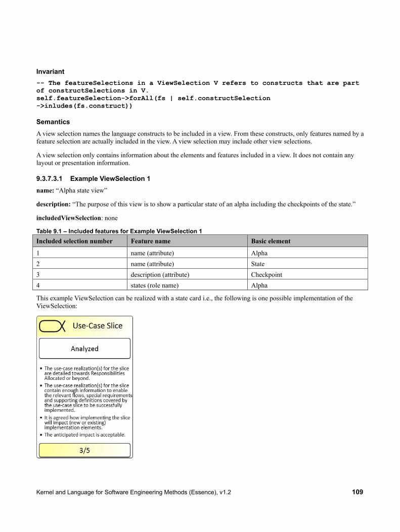
Kernel and Language for Software Engineering Methods (Essence), v1.2 109
Invariant -- The featureSelections in a ViewSelection V refers to constructs that are part of constructSelections in V. self.featureSelection->forAll(fs | self.constructSelection ->inludes(fs.construct))
Semantics A view selection names the language constructs to be included in a view. From these constructs, only features named by a feature selection are actually included in the view. A view selection may include other view selections.
A view selection only contains information about the elements and features included in a view. It does not contain any layout or presentation information.
9.3.7.3.1 Example ViewSelection 1 name: “Alpha state view”
description: “The purpose of this view is to show a particular state of an alpha including the checkpoints of the state.”
includedViewSelection: none
Table 9.1 – Included features for Example ViewSelection 1 Included selection number Feature name Basic element
1 name (attribute) Alpha 2 name (attribute) State 3 description (attribute) Checkpoint 4 states (role name) Alpha
This example ViewSelection can be realized with a state card i.e., the following is one possible implementation of the ViewSelection:

110 Kernel and Language for Software Engineering Methods (Essence), v1.2
So in Essence, the ViewSelection helps us define the subset of information to be shown on this specific type of card; however how to visualize the card (read: implementing the view) is not specified by the view itself but is instead something that is supported by the graphical syntax of the language.
In other words, it must be the purpose of the graphical syntax to implement (support) relevant views of the language.
9.3.7.3.2 Example ViewSelection 2 name: “Basic user view”
description: “The purpose of this view is to support a user that has very little interest in methods, but understands the value in having some kind of descriptions of the practices. This is expected to be the largest user group and the one that has high priority. This user will use a minimum number of language constructs that large user groups still can be expected to get value from. This view includes simple narrative descriptions of each practice of interest, including the work products of the practices.”
includedViewSelection: none
Table 9.2 – Included features for Example ViewSelection 2 Included selection number Feature name Basic element
1 name (attribute) Practice 2 briefDescription (attribute) Practice 3 description (attribute) Practice 4 elements (role name) Practice 5 name (attribute) WorkProduct 6 briefDescription (attribute) WorkProduct 7 description (attribute) WorkProduct 8 levelOfDetail (role name) WorkProduct 9 name (attribute) LevelOfDetail 10 briefDescription (attribute) LevelOfDetail 11 checkListItem (role name) LevelOfDetail 12 name (attribute) Checkpoint 13 description (attribute) Checkpoint NOTE: Selection 4 returns all elements of the practice, but only the ones used in subsequent selections are actually included. Selections 8-13 are all about including work product levels of detail in the view.
9.3.7.3.3 Example ViewSelection 3 name: “Extended user view including alphas”
description: “The purpose of this view is to extend and complement the basic user view above (example 2) by also including alphas and the state of alphas.”
includedViewSelection: “Basic user view” (example 2 above) + “Alpha state view” (example 1 above)

Kernel and Language for Software Engineering Methods (Essence), v1.2 111
Table 9.3 – Included features for Example ViewSelection 3 Included selection number Feature name Basic element
1 lowerBound (attribute) WorkProductManifest 2 upperBound (attribute) WorkProductManifest 3 alpha (role name) WorkProductManifest 4 workproduct (role name) WorkProductManifest 5 superAlpha (role name) AlphaContainment 6 subordinateAlpha (role name) AlphaContainment 7 lowerBound (attribute) AlphaContainment 8 upperBound (attribute) AlphaContainment
9.3.7.3.4 Example ViewSelection 4 name: “Yet another extended user view including activity flows”
description: “The purpose of this view is to extend and complement the extended user view above (example 3) by supporting complete activity flows; this will allow users to view sequences of activities, parallel activities, and understand how activities manipulate alphas and work products. Here the users can also view criteria for alpha state changes, and understand how to progress alpha states in terms of activities.”
includedViewSelection: “Extended user view including alphas” (example 3 above)
Table 9.4 – Included features for Example ViewSelection 4 Included selection number Feature name Construct
1 name (attribute) Activity 2 briefDescription (attribute) Activity 3 approach (attribute) Activity 4 inputWorkProduct (role name) Activity 5 outputWorkProduct (role name) Activity 6 inputAlpha (role name) Activity 7 outputAlpha (role name) Activity 8 completionCriterion (role name) Activity 9 description (attribute) CompletionCriterion 10 state (role name) CompletionCriterion
9.4 Composition and Modification
9.4.1 Introduction
Composition and modification of language constructs are done via merge and extension operations in the Essence language. They are the means by which more sophisticated and powerful constructs are built from smaller, simpler ones.

112 Kernel and Language for Software Engineering Methods (Essence), v1.2
Extension refers to the modification or customization of an element to suit a new context. For example, a Work Product defined in practice P1 may be modified in the context of a wider practice P2 that uses P1 as a component. The extension mechanism in Essence allows elements to be modified or customized, and has two key features:
• Extension is “aspectual” in the sense that the element being modified is oblivious of the modification.
• Extension is non-destructive, in the sense that the original element still exists and is available.
Merging refers to the capability to put elements together to build more powerful elements from simpler ones. The main use of merging is to put practices together where they are to be used together in an endeavor. In this context, merging allows the way of working on a project to be established by selecting and composing “best in class” practices addressing different aspects of the endeavor.
9.4.2 Notations and Conventions
Each instance of a language element owns a set of attributes. Each attribute can be thought of as a (label, value) pair. In particular each instance of a language element has an attribute with label = “name”.
The notation Λ(P1.xyz) denotes the set of attribute labels in P1.xyz. Type discipline guarantees that instances of language elements of the same type from different practices have the same set of attribute labels, and that the values of a given label have the same type. We allow that, in general, any label may have a null value.
Names of language elements are scoped by element groups. This means that, in the context of an element group, each name is unique. Names can be prefixed by the name of an element group to ensure uniqueness in larger contexts. If P3 is a Practice containing two Practices P1 and P2, then P1.xyz refers to the xyz that is provided by P1, and P2.xyz refers to the xyz that is provided by P2.
9.4.3 Extending
9.4.3.1 Basic Extension Algorithm Extending allows local changes to be made to the values of the attributes of an element in the context of an element group. Extension works via the use of an instance of ExtensionElement added to an element group and referencing the element being extended. If a language element is extended by an element group A, its original attribute values remain unchanged. However, from the perspective of A the values are seen as modified by the extension. Whether the results of extending are persisted or derived “on the fly” is a tooling issue and not part of the standard.
An association with role “targetElement” connects the ExtensionElement with the element to be extended. The attribute “targetAttribute” of ExtensionElement denotes the attribute to be extended. The attribute “extensionFunction” provides a post-condition in OCL for a function with signature:
extend(input : targetAttribute.oclType()) : targetAttribute.oclType()
In this signature:
• The input to the function is a single value for the attribute to be extended.
• The result of the function a single value to be used for the attribute.
• null is an allowed value, both on input and output.

Kernel and Language for Software Engineering Methods (Essence), v1.2 113
9.4.3.2 Renaming and Suppression The set of attributes that can be given an extension function includes the “name,” so it is possible for the extended object to be given a different name.
An extending function that sets the “name” attribute of an element to null suppresses this element. Hence it does not appear (is not visible) in the extended practice. Note that it is not “physically” deleted, so is still present and visible in the source (non-extended) practice. It is not allowed to define an extending function that suppresses language elements that have their attribute “isSuppressable” set to false.
An element may not be suppressed in an element group if it is referenced by another, unsuppressed, named element in the same group via an association that is mandatory for this element, resulting in a “dangling reference.” Tools should support “cascading extension” whereby the user is prompted to make suitable extensions to referencing elements when suppressing an element, to ensure that such “dangling references” are resolved.
Unnamed elements that represent binary links between language elements (i.e., links represented by “AlphaContainment,” “WorkProductManifest,” and “ActivityAssociation”) must be suppressed automatically if at least one of their ends is suppressed.
9.4.3.3 Standard Extension Functions A template post-condition for an extending function that provides a fixed output independent of the inputs (assuming attribute type String) looks like this:
post: result = “someFixedOutput”
A template post-condition for an extending function that performs a set of search and replace operation on the inputs (assuming attribute type String) looks like this:
post: result = input.regexReplaceAll(OrderedSet(Tuple(“somePattern”, “someReplacement”)))
Where regexReplaceAll is a function that performs a succession of string replacement based on pattern matching with POSIX Extended Regular Expressions.
At a minimum, tools are expected to supply extension functions that satisfy these post conditions, and may support more.
9.4.3.4 Precedence and Chaining Extensions are cumulative. If a given element is extended in element group A, and element group A is referenced by element group B which also extends x, then the extensions added to x by B are applied on top of those added by A.
Where an element is subject to both extensions and merging (see below) by the same element group, the extensions are applied first, before merging.
9.4.4 Merging
9.4.4.1 Overview Suppose that two element groups, B and C, are being composed in an element group A. If the set of names of all elements referenced by B and C are disjoint, then the discipline that each name is unique in the context of an element group is maintained. In the event that an element referenced by B and an element referenced by C have the same name, these two elements have to be merged in A. The merged element has the same name as the elements being merged, and ensures

114 Kernel and Language for Software Engineering Methods (Essence), v1.2
uniqueness of this name in A. The merging is local to A and does not affect the elements as seen in B or C, so the contents of B and C remain unchanged by the merging operation.
If two elements from practices being composed share the same name and type “by accident,” but are actually semantically distinct and should not be merged, then the name of one of one them must be changed using the Extension mechanism. This prevents the two elements being merged.
The language elements “AlphaContainment,” “WorkProductManifest,” and “ActivityAssociation” that do not have a “name” attribute and that represent links between language elements are automatically equipped with a derived name that is only visible for the purpose of detecting and handling merge conflicts. The name is composed of the names of the associated language elements by concatenating them in the order “superAlpha” + “subordianteAlpha”, “alpha” + “workProduct”, or “end1” + “end2”, respectively.
If certain conditions apply, merging is automatic, without the need for user input required. In other cases, where there is a “merge conflict”, user input is required to resolve the conflict. Whether the results of merging (with or without a Merge Resolution Object) are persisted or derived “on the fly” is a tooling issue and not part of the standard.
An element group in which there are unresolved merge conflicts is considered badly formed. Tools must detect badly formed element groups and prompt the user to resolve the issue. Also, tools should prevent a badly formed element group from being referenced (used by another element group) or being instantiated (at level-0) for enactment. If an element group that is already referenced or instantiated is rendered badly formed by an edit to the model, the tool should prompt the user to resolve the issue.
9.4.4.2 Basic Merging Algorithm Let A be the element group to show the merged element, B and C be two element groups contained by A, and B.x and C.x two elements of same name that are subject to the merge operation.
There is no “merge conflict” between B and C provided that:
a) B.x and C.x are of the same type, so that Λ(A.x) = Λ(B.x) = Λ(C.x).
b) For all λ in Λ(A.x), if both B.x and C.x offer a non-null value for λ, then the values offered must be equal.
If there is no merge conflict between B.x and C.x, then A.x is formed automatically, using the non-null value for attributes where one offers a value for that label and the other does not.
Where more than two elements are being merged and there is no merge conflict when the elements are considered pair-wise, then the automatically merged element can be formed in the obvious way.
9.4.4.3 Merge Conflict Resolution In the event of a merge conflict, user action is required to resolve the conflict as follows:
a) If B.x and C.x are not of the same type, one or other must be renamed using an ExtensionElement. The two elements are then not subject to merge.
b) If B.x and C.x are of the same type, but have a label where both offer a different non-null value, an element of type “MergeResolution” must be defined in A to give a value of the label in the merged object. This must be done for each label in A where there is a conflict.
When defining a MergeResolution, the attributes “targetName” and “targetAttribute” denote the element name and attribute whose value is being resolved. The value of “targetName” must be not null, as it is not possible (or meaningful) to merge suppressed elements.

Kernel and Language for Software Engineering Methods (Essence), v1.2 115
The attribute “resolutionFunction” provides a post-condition in OCL for a function with signature:
merge(input : Set(Tuple(String,targetAttribute.oclType())) : targetAttribute.oclType()
In this signature:
• The input to the function is a set of pairs, each pair being an element group name and the value for the target attribute in that element group. Suppose an attribute in an element with name x is given value “London” by the element named x in element group B and value “Paris” by the element named x in element group C. The input to a merge function for merging this attribute of x in an element group A that references both B and C would be: {(B, “London”),(C, “Paris”)}.
• The result of the function is a single value. This is the value to be used for the target attribute in A.
• null is an allowed value, both on input and output.
Using an element of type “MergeResolution” is mandatory if there is a merge conflict, but may be used even where there is no merge conflict to “override” the results of the standard merge. Since merging is based on name, it is not possible to define a MergeResolution on the “name” attribute of element being merged; so the “name” attribute can only be changed using an ExtensionElement.
9.4.4.4 Standard Merge Resolution Functions A template post-condition for a merge function that provides a fixed output independent of the inputs (assuming attribute type String) looks like this:
post: result = “someFixedOutput”
A template post-condition for a merge function that picks the value from one of the elements being merged looks like this:
post: result = input.selectValueFrom(“someElementGroupName”)
where selectValueFrom is a function that selects the second of the pair in input where the first in the pair equals the name supplied as a parameter.
At a minimum, tools are expected to supply merge functions that satisfy these post conditions, and may support more.
9.4.4.5 Precedence and Chaining If elements B.x and C.x are being merged in A, and B and/or C extend x, then it is the extended versions of x that are merged to form A.x. Similarly, if A merges B.x and C.x and another element group then references A, that element group may further extend A.x or even merge it with another element named x.
9.4.5 Example
As an example, Figure 9.17 shows the conceptual model of two practices P1 and P2 that are to be composed into a new practice P3. In the result of the composition, activity CC should be inserted between AA and BB as depicted at the bottom of the figure. This is an arbitrary choice by the practice author. Any other valid position for CC (including keeping it unconnected from AA and BB) would be possible as a target result as well.

116 Kernel and Language for Software Engineering Methods (Essence), v1.2
Figure 9.17 – Two practices P1 and P2 and their merge result P3. Elements that are referred to by P3 are shown in light grey. Elements that are modified by P3 are shown in dark grey. Elements that are owned by P3 are shown in black.
The original object structure of P1 and P2 is shown in Figure 9.18. To achieve the desired composition, several steps have to be taken:
• A new practice object P3 has to be created that refers to P1 and P2.
• A new extension element object has to be created for modifying the activity association from AA to BB in a way that it gets an association from AA to CC.
• A new activity association object has to be created for the link between CC and BB.
Note that there is also the alternative to modify the activity association from AA to BB in a way that it links CC and BB and consequently insert a new association from AA to CC. Both alternatives are equal with respect to complexity and result.

Kernel and Language for Software Engineering Methods (Essence), v1.2 117
The resulting object structure for P3 is shown in Figure 9.19. Since there are no merge conflicts in the resulting practice, no merge resolution objects are needed in this example.
Figure 9.18 – Object diagrams for P1 and P2

118 Kernel and Language for Software Engineering Methods (Essence), v1.2
Figure 9.19 – Partial object diagram for P3
In some cases, it is even not necessary to use an extension object in practice that merges other practices. An example for this case is shown in Figure 9.20. Practices P4 and P5 are very similar. They both add a new alpha as subordinate alpha to some other alpha owned by a kernel. These two practices can be composed to a new practice P6 without the need for an extension element object or merge resolution object. In P6, the kernel alpha will have two subordinate alphas, one from each of the composed practices.
However, a practice author may desire to sequence the subordinate alphas in a way that the one from P5 becomes subordinate alpha of the one from P4, instead of being subordinate to the kernel alpha. In this case, an extension element object is needed again as shown in Figure 9.21. It modifies the alpha containment in an appropriate way, changing the super alpha of the alpha contained in practice P5.
Figure 9.20 – Object diagrams for P4 and P5

Kernel and Language for Software Engineering Methods (Essence), v1.2 119
Figure 9.21 – Partial object diagrams for P6
9.5 Dynamic Semantics
9.5.1 Introduction
Since the language defines not only static elements like Alphas and Work Products, but also states associated with them, it can not only be used to express static method descriptions, but also dynamic semantics. Using the states of the single Alphas and their constituent Work Products, the overall state of a software engineering endeavor can be expressed. Based on this, denotational semantics can be defined for a function that supports a team in the enactment of a software engineering endeavor, by using the current state and a specification of the desired state to create a “to-do” list of activities to be performed by the team.
In a large or complex endeavor this function may be provided by a specialist tool. In smaller endeavors, where the overhead of tool support cannot be justified, the function represents a manual recipe that can be followed to determine guidance on how to proceed.
9.5.2 Domain classes
9.5.2.1 Recap of Metamodeling Levels As stated in 9.1.1, the Essence language is defined as a set of constructs which are language elements defined in the context of a metamodeling framework. In this framework all the constructs of the language, as described in 9.2, are at level 2.
• Level 3 – Meta-Language: the specification language, i.e., the different constructs used for expressing this specification, like “meta-class” and “binary directed relationship.”
120 Kernel and Language for Software Engineering Methods (Essence), v1.2
• Level 2 – Construct: the language constructs, i.e., the different types of constructs expressed in this specification, like “Alpha” and “Activity.”
• Level 1 – Type: the specification elements, i.e., the elements expressed in specific kernels and practices, like “Requirements” and “Find Actors and Use Cases.”
• Level 0 – Occurrence: the run-time instances, i.e., these are the real-life elements in a running development effort.
A Method Engineer using the Essence language to model the Practices and its associated Activities, Work Products, etc., would work at level 1. For instance, to describe an agile Practice like Scrum the Method Engineer would define activities such as “Sprint Planning Meeting” and “Daily Scrum,” and work products such as “Sprint Goal” at level 1. This is exactly analogous to a Software Engineer using the UML language (also described as constructs at level 2) to model an order processing system by define classes such as “Customer,” “Order,” and “Product” and use cases such as “Place an Order” and “Check Stock Availability” at level 1.
A team using Scrum on a project would be working at level 0. The project team would hold “Sprint Planning Meetings” and “Daily Scrums” and each would be a level 0 instance of the corresponding activity at level 1, and the goal set for each Sprint would be a level 0 instance of the “Sprint Goal” work product defined at level 1. This is exactly analogous to the creation of Customers “Bill Smith” and “Andy Jones” and products “Flange” and “Grommet” at level 0 in the executing order processing system.
9.5.2.2 Naming Convention In order to define the dynamic semantics it is necessary to refer to the inhabitants of levels 1 and 0 as well as those of level 2. In order to make it clear at which level a named term belongs, we use the following naming convention:
• X (an unadorned name) is a language Construct at level 2 as defined in 9.2, such as Alpha or Work Product.
• my_X (prefixed) is a Type at level 1 created by instantiating X. So if X is Work Product, my WorkProduct could be “Use case narrative.”
• my_X_instance is an Occurrence at level 0 by instantiating my_X. So if X is Work Product, my_WorkProduct_instance could be the use case narrative on how to withdraw cash from an atm.
This naming convention is used in the type signatures of functions of the dynamic semantics, so that it is clear to which level of the framework the terms used in the function signature belong. Consider the function guidance which returns a set of activities to be performed to a take an endeavor forward to the next stage. The type signature of this function is:
guidance: (my_Alpha, State)* → (my_Alpha, Activity*)*
The term my_Alpha in this type signature has a name prefixed with my_ and so is at level 1. The terms State and Activity, on the other hand, have an unadorned name and so are at level 2. Notice here that we allow a function type signature to use elements from different levels of the metamodeling framework.
9.5.2.3 Abstract Superclasses
9.5.2.3.1 Overview To ensure that occurrences at level 0 are endowed with the attributes they need to support the dynamic semantics, we define a set of abstract superclasses at level 1 from which the types defined at level 1 are subclassed. For instance the superclass my_Alpha ensures that every Alpha occurrence at level 0 will have attributes “instanceName,” “currentState,” “workProductInstances,” and “subAlphaInstances”. These superclasses are named consistently with the naming convention described above.

Kernel and Language for Software Engineering Methods (Essence), v1.2 121
The relationships between these superclasses and the classes created from the level 2 constructs are shown in Figure 9.22.
Figure 9.22 – The Essence language framework
9.5.2.3.2 my_Alpha The superclass to all level 1 types instantiated from the level 2 construct “Alpha”, i.e., the Alphas in some Kernel (such as “Requirements”) or Practice as well as to Sub-Alphas added by a particular Practice (such as “Use Case”).
Attributes instanceName : String [1] The name of an occurrence (e.g., Requirements for the XYZ
Project) currentState : my_State [1] A pointer to the current State of an occurrence (e.g., to the state
“Coherent”)
9.5.2.3.3 my_State The superclass to all level 1 types instantiated from the level 2 construct “State,” i.e., the States of some Alpha.
Attributes N/A
9.5.2.3.4 my_WorkProduct The superclass to all level 1 types instantiated from the level 2 construct “Work Product”, i.e., to all templates representing physical documents used in the software engineering endeavor, such as “Use Case narrative.”
Attributes instanceName : String [1] The name of an occurrence (e.g., Use Case Narrative for Withdraw
Cash)
122 Kernel and Language for Software Engineering Methods (Essence), v1.2
currentlevelOfDetail : my_LevelOfDetail [1]
A pointer to the current LevelOfDetail of an occurrence (e.g., to the level “Sketch”)
9.5.2.3.5 my_LevelOfDetail The superclass to all level 1 types instantiated from the level 2 construct “LevelOfDetail”, i.e., the level of detail of some work product.
Attributes N/A
9.5.3 Operational Semantics
9.5.3.1 Overview In this subclause we describe and illustrate the operational semantics. This covers how the level 0 model is created, how the state of the endeavor is tracked in the model, and how the model can be used to give advice based on how to progress the state of the endeavor. For the last of these we provide a formal denotational semantics.
The execution of operational semantics happens inside an execution environment. The execution environment can be a tool, a cognitive activity possibly supported by handwritten notes, or any combination of these and other suitable means. The notion of instance used in this subclause thus refers to an entity inside the execution environment that represents some entity outside the environment. Both the entity inside the execution environment and the one outside of it may or may not be physical. For example, a physical entity being a Work Product outside the execution environment can be represented by a non-physical entity in a tool. As an inverse example, the Alpha “Requirements” is a non-physical entity outside the execution environment, but can be represented physically by a piece of paper attached to a whiteboard. Since there is no automatic update from the outside to the inside of the execution environment, the manual creation and update of instances is explained in 9.5.3.2 and 9.5.3.3.
The execution environment may be used to collect and manage more information than the ones defined in the abstract superclasses in 9.5.2.3. It may also be used to execute more functions than the ones defined in 9.5.3.5 and 9.5.3.6.
Besides the instances belonging to the level 0 model, the execution environment holds a complete copy of the method description (i.e., the level 1 model) selected for the particular endeavor for reference. Any lookup to that model necessary for the creation of instances or during the execution of functions refers only to this copy. Any adaptation made to the method description by the team during the endeavor applies only to this copy as well. If two teams start to work according to the same method, adaptations made by one team do not affect the other team, because all adaptations stay local to copy of the method description owned by the respective execution environment. However, an adapted copy of a method description can at any point in time be declared to be a new method description and a team can then use a copy of this new method description in their execution environment.
9.5.3.2 Populating the Level 0 Model Generally, the appropriate Alpha instances and associated Work Product instances are created as soon as the respective Alpha is considered in the endeavor. Some may exist right from the start of the endeavor (such as the Alpha instances for Stakeholders or Requirements), while others may be created later, at the appropriate point in the conduct of a practice. This is usually the case for Sub-Alpha instances, which are instantiated as needed through the endeavor. The model of a practice is used as the basis for instantiating the appropriate sets of Alpha instances and associated Work Product instances, using the Work Product Manifests defined for the Practice as templates. Although the mechanisms of instantiation and updating Alpha instances and their associated Work Product instances can be formalized using computational semantics, it is not an automatic process and must be triggered explicitly by the team.

Kernel and Language for Software Engineering Methods (Essence), v1.2 123
A team is also free to create instances in their model that do not derive by instantiating from Practice templates, and thus tailor the use of a Practice or even depart from it to create a partially or completely customized approach.
9.5.3.3 Determining the Overall State Determining the overall state of the endeavor is done by determining the states of each individual Alpha instance in the endeavor. This is done using the checkpoints associated with each state of the respective state graphs; and the state is determined to be the most advanced in the state graph consistent with the currently met checkpoints. This means the state that has:
1. All currently fulfilled checkpoints met; and
2. No outgoing transition to a state that has also all currently fulfilled checkpoints met.
This is illustrated in Figure 9.23. Here the most advanced state of Software System “XYZ” consistent with the checkpoints that have been met (shown as ticked) is “Useable.”
Figure 9.23 – Determination of State using Check Points
The determination of Alpha instance states can happen at any point in time since evaluating the checkpoints is a manual activity. When checkpoints are evaluated the result can be that an Alpha instance regresses, its current state being set back to some earlier state of its lifecycle. This happens if re-evaluation determines that a checkpoint previously thought to have been met is now deemed not to have been met.
9.5.3.4 Generating Guidance In an actual running software engineering endeavor, a team will want to get guidance on what to do next.
Once the overall state of the endeavor is determined, the model can be used to generate such advice. This can be understood as a guidance function that takes a set of pairs of (Alpha instance and target State) as its argument and returns a set of newly instantiated Activities: a “to-do” list to be performed by the team. This function is invoked with an actual

124 Kernel and Language for Software Engineering Methods (Essence), v1.2
argument consisting of a set of pairs, each pair consisting of a my_Alpha_instance (at level 0) and a my_State (at level 1). For each pair the function returns guidance on how to progress each my_Alpha_instance to its target state my_State. This guidance is of the form of a set of newly instantiated activities (at level 0) for each my_Alpha_instance, constituting a to-do list to be performed by the team to advance its state. The essential idea is to assemble the to-do list by examining each Alpha instance given to the function and finding those activities that have the target state of that Alpha instance among its completion criteria.
Note that an Essence model does not specify how the team works on a set of activities. This is the dictated by the policies, rules or advice of the practices being used on the endeavor. These may require or suggest that certain activities should be prioritized, done in a particular sequence, divided among sub-teams, and so on. The team uses its expertise in the practices to work out exactly how to perform the activities required. Nor is there any ultimate guarantee that the team will follow the advice or perform the suggested activities competently: in that sense the model is an “open loop” control system. However, regular re-evaluation of the checkpoints and the consequent re-setting of the Alpha instance states will provide feedback to the team on whether or not their work is advancing as hoped.
Several other functions can be defined to measure the progress and health of the endeavor, for instance to determine whether the right set of my_Alpha_Instances and my_WorkProduct_Instances is in place, or to determine whether the endeavor has reached its final state. These have not been defined here.
9.5.3.5 Formal definition of the Guidance Function
In this subclause, we provide a formal description of the operational semantics in terms of the function guidance using VDM-SL in mathematical syntax. This function takes a set of pairs of (Alpha instance and target State) as its argument and returns a set of to-do lists, one for each Alpha instance and target State provided to the function.
The essential idea is to compile the to-do lists by examining each Alpha instance given to the function and finding those activities that have the target state of that Alpha instance among its completion criteria. However, the target state specified for an Alpha instance may not be the next state in the state graph of the Alpha, and so a function statesAfter is used to find the intermediate states. The to-do list generated consists of the activities required to progress the Alpha instance through all these states in order to reach the specified target.
First we specify the statesAfter function. Suppose that a state graph has a sequence of states S0, S1, S2, S3. If statesAfter is called with (S0, S3) it will return {S1, S2, S3}. In other words, all the states passed through to get to S3
but not including the starting state S0. This is easier to specify in terms of a function fullPath that generates the full set of states including the starting state. So if fullPath is called with (S0, S3) it will return {S0, S1, S2, S3}.
statesAfter: (State, State) → State* statesAfter (s1, s2) = fullPath(s1, s2) – {s1} fullPath: (State, State) → State* fullPath (s1, s2) = if ((s1.successor = null) ∨(s1 = s2)) {s1} else {s1} ∪fullPath(s1.successor, s2)
We use this to specify the guidance function. Each (Alpha instance, target State) pair is taken in turn.
guidance: (my_Alpha, State)* → (my_alpha, Activity*)* guidance (cas) = let as ∈cas in to_do(as) ∪ guidance (cas− {as})

Kernel and Language for Software Engineering Methods (Essence), v1.2 125
The to_do function takes a single (Alpha instance, target State) pair and creates the set of activities that are recommended to progress the Alpha instance to the required target State. This is done by finding those activity types that have the target state or any intermediate state among its completion criteria. The function statesAfter is used to find the intermediate states.
Note that the completion criteria (defined at level 1) are defined using activity types (at level 1). The function to_do determines the set of activity types required for each Alpha instance.
to_do: (my_Alpha, State) → (my_alpha, Activity*) to_do (α, σ) = let cw = { w | (σ’ ∩completionStates(w.completionCriterion) ≠∅) ∧ (σ’ ∈statesAfter(α.currentState,σ)) } in (α,cw)
Finally, we specify the function completionStates which is used by the to_do function to determine the set of states forming the completion criteria of an activity.
completionStates: CompletionCriterion* → State* completionStates (ccc) =
let cc ∈ ccc and rs = cc.state in rs∪completionStates(ccc – {cc})
9.5.3.6 Further functions As well as the Guidance Function, a number of other functions can be defined to support enactment. This subclause describes a number of these as illustration. It is expected that any Essence tool will support at least these functions.
The to do function used to generate guidance makes use of the property “currentState” on my Alpha. It is not specified whether tool vendors allow users to set this property directly or consider it a derived property. However, if it is handled as a derived property, it has to be derived in the following way:
derive_current_state: my_Alpha→my_State derive_current_state (a) = let s = { s | s ∈a.states∧ {ps | ps.successor=s} = ∅} in fullfilledSuccessorState(s) fullfilledSuccessorState: my_State→my_State fullfilledSuccessorState (s) = if (s.successor = ∅) {s} else let mc = {c | c ∈s.successor.checkpoints∧ not c.isFullfilled} in (if (mc = ∅) {fullfilledSuccessor(s.successor)} else {s}) The same can be done for “currentLevelOfDetail” on my_WorkProduct:
derive_current_level_of_detail: my_WorkProduct→my_LevelOfDetail derive_current_level_of_detail (wp) = let s = { l | l ∈wp.levelOfDetail∧ {pl | pl.successor=l} = ∅} in fullfilledSuccessorLevel(l)

126 Kernel and Language for Software Engineering Methods (Essence), v1.2
fullfilledSuccessorLevel: my_LevelOfDetail→my_LevelOfDetail fullfilledSuccessorLevel (l) = if (l.successor = ∅) {l} else let mc = {c | c ∈s.successor.checkpoints∧ not c.isFullfilled} in (if (mc = ∅) {fullfilledSuccessor(s.successor)} else {l}) Before using the guidance function on a set of (Alpha instance, target State) pairs, a user may want to derive a set of sensible target states from the current states.
nextAlphaStatesToReach: my_Alpha* →my_State* nextAlphaStateToReach(a) = let oa∈ a in oa.currentState.successor∪nextAlphaStateToReach(a – {oa})
9.6 Adaptation
9.6.1 Alignment of Level 0 and Level 1
A key objective of Essence is to be able to support “adaptation,” meaning that a practices and methods can be adapted to meet particular project needs and to incorporate refinements that emerge from experience gained through enactment. It is required that such adaptation can take place during the course of a project, and this means that it must be possible to amend the level 1 model of a Method at a time when instances of the Method at level 0, representing enactments of the Method on an endeavor, are in existence. As a level 0 model must always be a valid instance of level 1, tool functionality is required to keep the two properly aligned.
What this involves depends on how much level 0 information the Essence tool holds. While, by definition, the Essence tool is the host of the level 1 model (defining the Kernel and Method being used, and the associated Practices, Alphas, Sub-Alphas, Activity Spaces, Activities, and Work Products) it may only hold a partial level 0 model. The content of the level 0 model hosted in the Essence Tool is driven by the key enactment aims of Essence:
• To enable the overall state of the endeavor to be recorded and tracked.
• To support moving the endeavor forward using the functions of the Dynamic Semantics.
• Meeting these enactment aims generally means that the Essence tool hosts the key level 0 instances of an endeavor, including the Method itself.
• The Kernel used by the Method, along with its top level Alphas and Activity Spaces.
• The Practices used by the Method, along with top level Alphas and Work Products associated with each Practice.
However much of the detailed level 0 information generated on an endeavor during enactment may not be in the Essence tool itself but federated across a whole set of tools and environments used on a project, such as:
• Project Planning Tools
• Requirements Management Tools
• Risk and Issue Repositories/Management Tools

Kernel and Language for Software Engineering Methods (Essence), v1.2 127
• CASE Tools and IDEs (for various models and code artifacts)
• Content Management Systems/Folders/Repositories of documents, spreadsheets, etc.
In some cases it may be appropriate to keep “proxy” information about such items in the Essence tool. For instance, details of project risks may be maintained in a specialized Risk Management Tool, but a corresponding set of Risk Alphas may be kept in the Essence tool to represent the state of each Risk for overall management purposes. In this case, it is clearly necessary to keep the Essence Risk Alphas and the detail in the Risk Management Tool properly synchronized.
In the context of adaptation it is necessary to think about both of:
• Internal alignment between level 1 and level 0, for that part of the level 0 model that is hosted by Essence.
• External alignment between level 1 and level 0, for that part of the level 0 model that is federated to other tools.
These are considered below, after a general discussion of the adaptation mechanism.
9.6.2 Adaptation Approach
The general approach to adaptation is provided by the extension and merging mechanisms described earlier in 9.4.
For concreteness, consider this example: An endeavor is using a method M that combines practices P1 and P2. So M, P1 and P2 have been described at level 1 in Essence and instantiated (in Essence and across the supporting tool federation) for enactment. Now suppose that, with the endeavor underway and the level 0 model populated, P1 is to be refined and the project migrated to use the refined version. Typically, this is done as follows:
• First a new Practice P1’ is created that references P1and extends (modifies) those elements that are to be refined. These elements are given new names in their extended versions in P1’.
• Secondly, the new Practice P1’ is added to M. Elements in P1’ that are not refined, so are the same as the old version in P1, are automatically merged.
The level 0 model is still a valid instance of the new level 1 model of M, but at this stage none of the new (refined) elements in P1’ are populated at level 0. Population of these requires migration, and the Essence tool should support this as described in the following subclauses.
9.6.3 Internal Migration
This subclause covers tool support for migration of level 0 instances that are hosted in the Essence tool. In this case, the tool should support automatic migration as described below.
Suppose that an element x in P1 has been refined to x’ in P1’. The user can ask the Essence tool to create a “migration function” x -> x’. To do this, the tool provides functionality for the user to:
• Enter an OCL function for each attribute of x’ specifying how this attribute should be populated from the existing level 0 model.
• Specify whether, after creating an instance of x’ the old instance of x should be retained or deleted.
(The reason for allowing the x instance to be retained is that a refinement might “split” x into two elements: x’ and x’’. In this case, two migration functions (x -> x’ and x –> x’’) would be needed and an x instance only deleted after the second is run.)

128 Kernel and Language for Software Engineering Methods (Essence), v1.2
The user can then ask the Essence tool to execute the migration. The tool will prompt the user to specify whether all instances of x are to be migrated, or allow the user to select those that are to be migrated. It will then execute the migration function, which will create an instance of x’ for each selected instance of x and populate its attributes using the OCL function. It will then (if requested) delete the instance of x.
Note that, because the merged model for M supports both x and x’, if desired the migration may be undertaken incrementally by running the migration function repeatedly over time. Once all instances of “legacy” elements (such as x) have been migrated to their refined version (x’), P1 can be deleted from M.
9.6.4 External Migration
This subclause covers tool support for migration of level 0 instances that are not hosted in the Essence tool. In this case, how migration is handled depends on whether and how level 0 information in other tools are synchronized with the Essence tool.
Where the Essence tool holds “proxies” of level 0 items, migration may be handled as described for internal migration. Alternatively the mechanism used to maintain synchronization between the detail in federated systems and the Essence model may be used to achieve migration, by importing new proxy data that conform to the refined model.
For cases where the level 0 data is entirely in a federated tool, any required migration is handled entirely in the external tool.
9.7 Graphical Syntax
9.7.1 Specification Format
The graphical syntax provides a visual form for each construct. Each graphical notation is introduced in a separate subclause that provides a description and symbol of the syntax. This subclause includes subclauses for Style Guidelines and Examples when applicable.
Diagrams are introduced by listing the graphical nodes and links to be included in the diagrams. Each node and link refers to the syntax specification of an individual element.
9.7.2 Relevant Symbols and Diagram Interchange Metamodel
Most of the constructs in the abstract syntax of the Kernel Language require a visual representation in terms of a symbol for the purpose of being visualized. However, constructs like Completion Criterion and Required Competency may not require symbols of their own but are instead visualized textually only. Thus the graphical syntax defines four main ways of representing language elements: nodes, links, labels, and texts. They can be used on general diagrams as well as on two types of cards. The relationships between these elements and the Diagram Interchange Metamodel are shown in Figure 9.24.

Kernel and Language for Software Engineering Methods (Essence), v1.2 129
Figure 9.24 - Metamodel of the graphical syntax for diagram interchange
9.7.3 Default Notation for Meta-Class Constructs
The default notation for a meta-class construct in the abstract syntax is a solid-outline rectangle containing the name of the construct’s type (level 1 in the abstract syntax). The name of the construct itself (level 2 in the abstract syntax) can be shown in guillemets above the type name. Alternatively, if the meta-class construct defines its own distinct symbol, this symbol can be shown above the type name in the rectangle.
This provides a default and unique visualization of each meta-class construct in the abstract syntax.
Style Guidelines
• Center the name of the construct’s type in boldface.
• Center the name of the construct itself in plain face within guillemets above the type name, or alternatively:
• Include the symbol of the construct above the type name and aligned to the right.

130 Kernel and Language for Software Engineering Methods (Essence), v1.2
Examples
Figure 9.25 – Example visualizations of the Alpha meta-class construct and its Software System type
9.7.4 View 1: Alphas and their States
9.7.4.1 Alpha An Alpha is visualized by the following symbol, either containing the name of the Alpha or with the name of the Alpha placed below the symbol:
Figure 9.26 – Alpha symbol
Style Guidelines
• Center the name of the Alpha in boldface, either within the symbol or below the symbol.
Examples
Figure 9.27 – Software System Alpha
9.7.4.2 Alpha Association An Alpha Association is visualized by a solid line connecting two associated Alphas. The line may consist of one or more connected segments. The association line is adorned with the name of the association, and optionally with the lower and upper bounds of the associated alphas placed near the end of the line connecting each alpha.
Figure 9.28 – Alpha Association symbol
Style Guidelines
• Center the name of the Alpha Association above or under the association line in plain face.
• An open arrowhead ‘>’ or ‘<’ next to the name of the association and pointing along the association line indicates the order of reading and understanding the association. This arrowhead is for documentation purposes only and has no general semantic meaning.

Kernel and Language for Software Engineering Methods (Essence), v1.2 131
• If lower and upper bounds are included, use the notation “<lower-bound>..<upper-bound>” such as for example “0..3”; if the lower and upper bound are the same, exclude the “..” and just show one of the bounds. Let a bound value of -1 imply an “arbitrary number of instances” and denote this as “*”.
Examples
Figure 9.29 – Alpha Association between the Requirements Alpha and the Software System Alpha, read as: “The Software System fulfills the Requirements.”
9.7.4.3 Kernel A Kernel is visualized by a hexagon containing a cogwheel; either containing the name of the Kernel or with the name of the Kernel placed below the symbol.
Figure 9.30 – Kernel symbol
Style Guidelines
• Center the name of the Kernel in boldface, either within the symbol or below the symbol.
Examples
Figure 9.31 – Kernel for Software Engineering

132 Kernel and Language for Software Engineering Methods (Essence), v1.2
9.7.4.4 State A State is visualized by a rectangle with rounded corners containing the name of the State.
Figure 9.32 – State symbol
Style Guidelines
• Center the name of the State in boldface.
Examples
Figure 9.33 – Milestones Agreed State
9.7.4.5 State Successor A State Successor association is visualized by a solid line with an open arrowhead connecting a State with its successor State. The line may consist of one or more connected segments.
Figure 9.34 – State Successor association
Examples
Figure 9.35 – Transition from the Objectives Agreed State to the Plan Agreed State
9.7.4.6 Diagrams
9.7.4.6.1 Alpha Structure Diagram Table 9.5 – Graphical nodes in Alpha Structure diagrams Node Type Symbol Reference
Alpha
9.7.4.1 Alpha.

Kernel and Language for Software Engineering Methods (Essence), v1.2 133
Table 9.6 – Graphical links in Alpha Structure diagrams Link Type Symbol Reference
Alpha Association 9.7.4.2 Alpha Association.
Examples Refer to kernel examples.
9.7.4.6.2 State Graph Diagram Table 9.7 – Graphical nodes in State Graph diagrams Node Type Symbol Reference
State
9.7.4.4 State.
Table 9.8 – Graphical links in State Graph diagrams Link Type Symbol Reference
State Successor 9.7.4.5 State Successor.
Style Guidelines
• Place the start state at the top of the diagram, and the stop state at the bottom of the diagram.
• Use State successors to visualize a logical sequence through states, from start to stop. Only visualize alternative successors when there are mutually exclusive state sets involved in the sequence from start to stop. Within a specific sequence from start to stop, we may assume that any loop or alternation is permitted without visualizing corresponding successors.

134 Kernel and Language for Software Engineering Methods (Essence), v1.2
Examples
Figure 9.36 – State Graph example
9.7.4.7 Cards
9.7.4.7.1 Overview As a complement to the symbols and diagrams we use a card metaphor (as in 5x3 inch index cards) to visualize the most important aspects of an element in the Kernel Language. A card presents a succinct summary of the most important things you need to remember about an element. In many cases, all that a practitioner needs to be able to apply a kernel or a practice is a corresponding set of cards.
In particular, cards are straightforward to manifest as physical entities (print them on paper) which makes them very hands-on and natural for practitioners to put on the table, play around with, and reason about; all for the purpose to guide practitioners in their way of working.
9.7.4.7.2 The Anatomy of a Definition Card A definition card is visualized as a solid-outline rectangle in landscape format containing a mix of symbols and textual syntax related to the element. The following is a basic anatomy although variations are allowed:

Kernel and Language for Software Engineering Methods (Essence), v1.2 135
Figure 9.37 – A basic definition card anatomy to visualize an element
Style Guidelines
• Place the owner name in boldface at the top-right of the card and use a font with smaller size than for the element name top-left.
9.7.4.7.3 Alpha Definition Card An Alpha definition card is defined as follows:
Card left-hand-side: State Graph Diagram for the Alpha.
Card right-hand-side: Brief Description of the Alpha, as well as a listing of its description and contained elements (sub-Alphas or Work Products, if any).

136 Kernel and Language for Software Engineering Methods (Essence), v1.2
Examples
Figure 9.38 – Software System Alpha Definition Card
9.7.4.7.4 The Anatomy of a Detail Card A detail card is visualized as a solid-outline rectangle in portrait format containing a mix of symbols and textual syntax related to the element. The following is a basic anatomy although variations are allowed:
Figure 9.39 – A basic detail card anatomy to visualize an element
This card anatomy is applicable to the following elements:

Kernel and Language for Software Engineering Methods (Essence), v1.2 137
• Basic Elements such as Alpha, Work Product, Activity Space, Activity, Competency and Pattern.
• Language Elements such as State, Level of Detail and Competency Level.
• Element Groups such as Practice and Method.
Style Guidelines
• Place the element name in boldface centered in the card header and use a font with larger size than what is used in the card body.
• If the card is for a Basic Element that has an icon (refer to the “icon” attribute in subclause 9.3.2.2), place the icon top right in the card body.
• When the element is owned by an element group, place the element group symbol or icon (if it exists) to the left in the card footer.
• For Language Elements such as State, Level of Detail and Competency Level:
o Let the card header visualize the owning element (Alpha, Work Product or Competency respectively) and let the card body visualize the element as a sub-element.
o Visualize the order of the sub-element as for example “4/6” in the card footer.
o If several cards are needed to present the details (such as checkpoints) of the sub-element, include a card number in the card footer, for example “Card 1 of 2” for card number 1 out of 2 in total.
9.7.4.7.5 Alpha State Detail Card The following is a basic anatomy although variations are allowed:
• Card header: Alpha symbol and name at the top, followed by a State symbol and name.
• Card body: Checklist of the Alpha State. If provided, the short description of a checkpoint is used as the default.
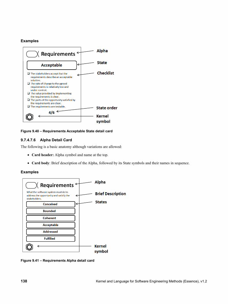
138 Kernel and Language for Software Engineering Methods (Essence), v1.2
Examples
Figure 9.40 – Requirements Acceptable State detail card
9.7.4.7.6 Alpha Detail Card The following is a basic anatomy although variations are allowed:
• Card header: Alpha symbol and name at the top.
• Card body: Brief description of the Alpha, followed by its State symbols and their names in sequence.
Examples
Figure 9.41 – Requirements Alpha detail card

Kernel and Language for Software Engineering Methods (Essence), v1.2 139
9.7.5 View 2: Sub-Alphas and Work Products
9.7.5.1 Work Product A Work Product is visualized by the following symbol, either containing the name of the Work Product or with the name of the Work Product placed below the symbol:
Figure 9.42 – Work Product symbol
Style Guidelines
• Center the name of the Work Product in boldface, either within the symbol or below the symbol.
Examples
Figure 9.43 – Iteration Plan Work Product
9.7.5.2 Alpha Containment An Alpha Containment is visualized by a solid line connecting a super- and a sub-Alpha. The line may consist of one or more connected segments. The line is adorned with a filled diamond placed at the end of the line connecting the super-Alpha; and with the lower and upper bounds of the sub-Alpha placed near the end of the line connecting the sub-Alpha.
Figure 9.44 – Alpha Containment symbol
As an alternative, an Alpha Containment can be visualized by encompassing the sub-Alpha symbols within the super-Alpha symbol. In this case, the Alpha symbol is adorned with a +/- sign to denote whether it is collapsed (+) and thereby not showing its content, or whether it is expanded (-) and showing its content.

140 Kernel and Language for Software Engineering Methods (Essence), v1.2
Style Guidelines
• Arrange the line vertically with the super-Alpha on top and the sub-Alpha at the bottom, thereby visualizing a top-down hierarchy.
• If there are two or more sub-Alphas of the same super-Alpha, they may be visualized as a tree by being placed at the same horizontal level and by merging the lines to the super-Alpha into a single segment.
• If lower and upper bounds are included, use the notation “<lower-bound>..<upper-bound>” such as for example “0..3”; if the lower and upper bound are the same, exclude the “..” and just show one of the bounds. Let a bound value of -1 imply an “arbitrary number of instances” and denote this as “*”.
• If the encompassment notation is used, place the +/- sign top-left within the Alpha symbol, and when expanded, place the name of the Alpha under the symbol.
Examples
Figure 9.45 – Software System super-Alpha and three sub-Alphas: Architecture, Component, and Test with visualized bounds
9.7.5.3 Work Product Manifest A Work Product Manifest is visualized by a solid line connecting an Alpha and a Work Product. The line may consist of one or more connected segments. The line is adorned with a filled diamond placed at the end of the line connecting the Alpha; and with the lower and upper bounds of the Work Product placed near the end of the line connecting the Work Product.
Figure 9.46 – Work Product Manifest symbol
Note that this is the same symbol as the Alpha Containment symbol, however the symbols are discriminated based on their context; that is, whether two Alphas are connected (Alpha Containment), or whether an Alpha and a Work Product are connected (Work Product Manifest).

Kernel and Language for Software Engineering Methods (Essence), v1.2 141
As an alternative, a Work Product Manifest can be visualized by encompassing the Work Product symbols within the Alpha symbol. In this case, the Alpha symbol is adorned with a +/- sign to denote whether it is collapsed (+) and thereby not showing its content, or whether it is expanded (-) and showing its content.
Style Guidelines
• Arrange the line horizontally with the Alpha to the left and the Work Product to the right, thereby visualizing a left-to-right hierarchy.
• If there are two or more Work Products of the same Alpha, they may be visualized as a tree by being placed at the same horizontal level and by merging the lines to the Alpha into a single segment.
• If lower and upper bounds are included, use the notation “<lower-bound>..<upper-bound>” such as for example “0..3”; if the lower and upper bound are the same, exclude the “..” and just show one of the bounds. Let a bound value of -1 imply an “arbitrary number of instances” and denote this as “*”.
• If the encompassment notation is used, place the +/- sign top-left within the Alpha symbol, and when expanded, place the name of the Alpha under the symbol.
Examples
Figure 9.47 – Software System Alpha and three Work Products: Design Model, Build, and Release Description with visualized bounds
9.7.5.4 Level of Detail A Level of Detail is visualized by a trapezoid containing the name of the Level of Detail.
Figure 9.48 – Level of Detail symbol
Style Guidelines
• Center the name of the Level of Detail in boldface.
• Use a dashed border line in the trapezoid for a Level of Detail that is a successor (or transitive successor) of a sufficient level.

142 Kernel and Language for Software Engineering Methods (Essence), v1.2
Examples
Figure 9.49 – Sketch Level of Detail
Figure 9.50 – Generator-ready Model Level of Detail that is a successor of a sufficient level
9.7.5.5 Level of Detail Successor A Level of Detail Successor association is visualized by a solid line with an open arrowhead connecting two Levels of Detail. The line may consist of one or more connected segments.
Figure 9.51 – Level of Detail Successor
Examples
Figure 9.52 – Formal Model Level of Detail is a successor of the Sketch Level of Detail
9.7.5.6 Practice A Practice is visualized by a hexagon; either containing the name of the Practice or with the name of the Practice placed below the symbol.
Figure 9.53 – Practice symbol
Style Guidelines
• Center the name of the Practice in boldface, either within the symbol or below the symbol.

Kernel and Language for Software Engineering Methods (Essence), v1.2 143
Examples
Figure 9.54 – Scrum Essentials Practice
9.7.5.7 Diagrams
9.7.5.7.1 Alpha Hierarchy Diagram Table 9.9 – Graphical nodes in Alpha Hierarchy diagrams Node Type Symbol Reference
Alpha
9.7.4.1 Alpha.
Work Product
9.7.5.1 Work Product.
Table 9.10 – Graphical links in Alpha Hierarchy diagrams Link Type Symbol Reference
Alpha Containment
See 9.7.5.2 Alpha Containment.
Work Product Manifest
See 9.7.5.3 Work Product Manifest.
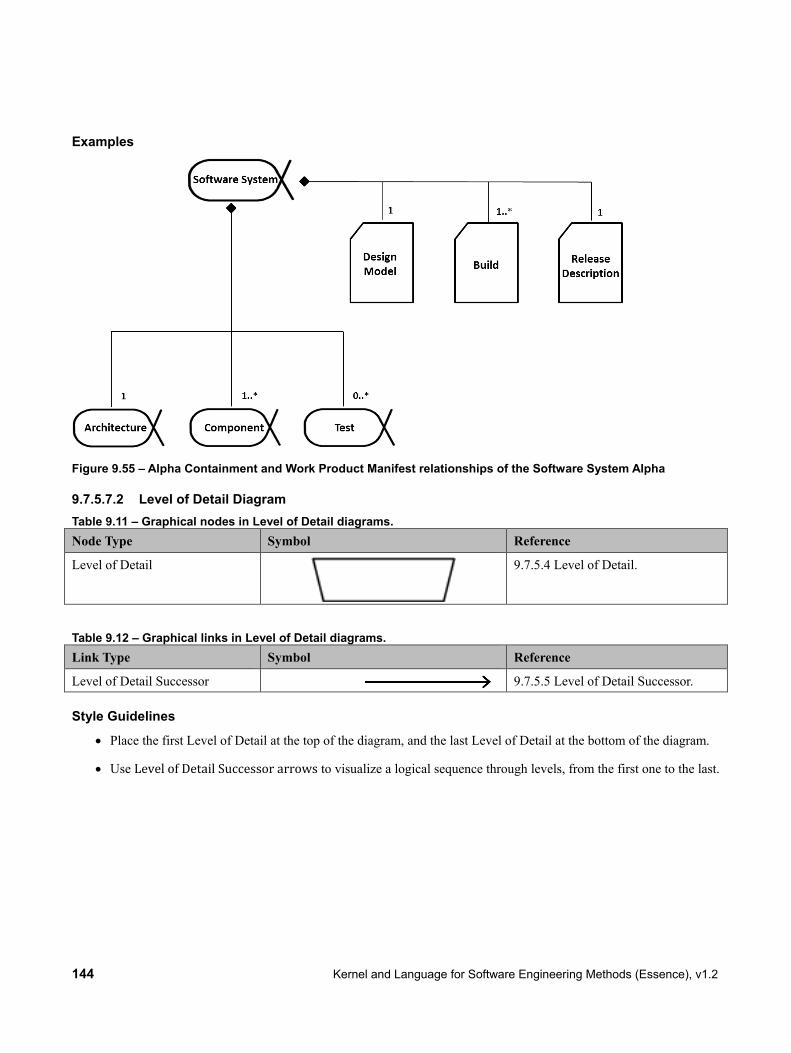
144 Kernel and Language for Software Engineering Methods (Essence), v1.2
Examples
Figure 9.55 – Alpha Containment and Work Product Manifest relationships of the Software System Alpha
9.7.5.7.2 Level of Detail Diagram Table 9.11 – Graphical nodes in Level of Detail diagrams. Node Type Symbol Reference
Level of Detail
9.7.5.4 Level of Detail.
Table 9.12 – Graphical links in Level of Detail diagrams. Link Type Symbol Reference
Level of Detail Successor 9.7.5.5 Level of Detail Successor.
Style Guidelines
• Place the first Level of Detail at the top of the diagram, and the last Level of Detail at the bottom of the diagram.
• Use Level of Detail Successor arrows to visualize a logical sequence through levels, from the first one to the last.

Kernel and Language for Software Engineering Methods (Essence), v1.2 145
Examples
Figure 9.56 – Level of Detail diagram example
9.7.5.8 Cards
9.7.5.8.1 Work Product Definition Card A Work Product definition card is defined as follows:
• Card left-hand-side: Level of Detail Diagram for the Work Product.
• Card right-hand-side: Brief Description of the Work Product, as well as a listing of related elements (Alphas or Work Products, if any).
Examples
Figure 9.57 – Architectural Model Work Product Definition Card

146 Kernel and Language for Software Engineering Methods (Essence), v1.2
9.7.5.8.2 Level of Detail Card The following is a basic anatomy although variations are allowed:
• Card header: Work Product symbol and name at the top, followed by a Level of Detail symbol. Note that the Level of Detail symbol shall have a dashed border line if the Level of Detail is a successor (or transitive successor) of a sufficient level.
• Card body: Checklist of the Work Product Level of Detail. If provided, the short description of a checkpoint is used as the default.
Examples
Figure 9.58 – Architectural Model Level of Detail card
9.7.5.8.3 Work Product Detail Card The following is a basic anatomy although variations are allowed:
• Card header: Work Product symbol and name at the top.
• Card body: Brief description of the Work Product, followed by its Level of Detail symbols and their names in sequence.

Kernel and Language for Software Engineering Methods (Essence), v1.2 147
Examples
Figure 9.59 – Architectural Model Work Product detail card
9.7.5.8.4 Practice Detail Card The following is a basic anatomy although variations are allowed:
• Card header: Practice name at the top.
• Card body: Brief description of the Practice, followed by its owned elements symbols (or corresponding icons if they exist) and their names.

148 Kernel and Language for Software Engineering Methods (Essence), v1.2
Examples
Figure 9.60 – Daily Stand-Up Practice detail card
9.7.5.8.5 Method Detail Card The following is a basic anatomy although variations are allowed:
• Card header: Method name at the top.
• Card body: Brief description of the Method, followed by its composed practice symbols (or corresponding icons if they exist) and their names.
Examples
Figure 9.61 – Starter Method detail card

Kernel and Language for Software Engineering Methods (Essence), v1.2 149
9.7.6 View 3: Activity Spaces and Activities
9.7.6.1 Activity An Activity is visualized by the following symbol, either containing the name of the Activity or with the name of the Activity placed below the symbol:
Figure 9.62 – Activity symbol
Style Guidelines
• Center the name of the Activity in boldface, either within the symbol or below the symbol.
Examples
Figure 9.63 – Sprint Retrospective Activity
9.7.6.2 Activity Space An Activity Space is visualized by the following dashed-outline symbol, either containing the name of the Activity Space or with the name of the Activity Space placed below the symbol:
Figure 9.64 – Activity Space symbol
Style Guidelines Center the name of the Activity Space in boldface, either within the symbol or below the symbol.
Examples
Figure 9.65 – Specify the Software Activity Space

150 Kernel and Language for Software Engineering Methods (Essence), v1.2
9.7.6.3 Activity Association (“part-of” kind) An Activity Association that is of the “part-of” kind is visualized by a solid line connecting an Activity Space and an Activity. The line may consist of one or more connected segments. The line is adorned with a filled diamond placed at the end of the line connecting the second member of the association.
Figure 9.66 – Activity Association (“part-of” kind) symbol
Note that this is the same symbol as the Alpha Containment and Work Product Manifest symbol, however the symbols are discriminated based on their context; that is, whether two Alphas are connected (Alpha Containment), or whether an Alpha and a Work Product are connected (Work Product Manifest), or whether Activity Spaces and/or Activities are connected (Activity Association).
As an alternative, an Activity Association can be visualized by encompassing the Activity symbols within the Activity Space symbol. In this case, the Activity Space symbol is adorned with a +/- sign to denote whether it is collapsed (+) and thereby not showing its content, or whether it is expanded (-) and showing its content.
Style Guidelines
• Arrange the line horizontally with the Activity Space to the left and the Activity to the right, thereby visualizing a left-to-right hierarchy.
• If there are two or more Activities of the same Activity Space, they may be visualized as a tree by being placed at the same horizontal level and by merging the lines to the Alpha into a single segment.
• If the encompassment notation is used, place the +/- sign top-left within the Activity Space symbol, and when expanded, place the name of the Activity Space under the symbol.
Examples
Figure 9.67 – Specify the Software Activity Space and two Activities: Identify Use Cases and Specify Use Cases
Figure 9.68 – Specify the Software Activity Space, encompassment notation with expanded symbol

Kernel and Language for Software Engineering Methods (Essence), v1.2 151
Figure 9.69 – Specify the Software Activity Space, encompassment notation with collapsed symbol
9.7.6.4 Activity Association (other than the “part-of” kind) An Activity Association that is not of the “part-of” kind is visualized by a solid line connecting two Activity and/or Activity Space symbols. The line may consist of one or more connected segments. The line is adorned with a filled triangular arrowhead placed at the end of the line connecting end2.
The association line is optionally adorned with the kind of the association.
Figure 9.70 – Activity Association symbol.
Style Guidelines
• Lines may be drawn using curved segments.
• Center the kind of the Activity Association above or under the association line in plain face.
• If the Activity Association kind is “start-before-start” it is assumed to be most common and can thereby be excluded; other kinds should be explicitly shown.
Examples
Figure 9.71 – Activity Association among four activities in a Scrum Essentials practice

152 Kernel and Language for Software Engineering Methods (Essence), v1.2
9.7.6.5 Competency A Competency is visualized by a 5-point star symbol with the name of the Competency placed below the symbol:
Figure 9.72 – Competency symbol
Style Guidelines
• Center the name of the Competency in boldface below the symbol.
Examples
Figure 9.73 – Leadership Competency
9.7.6.6 Competency Level A Competency Level is visualized by a rectangle containing the name and number of the Competency Level. The level is visualized by surrounding it with a 5-point star.
Figure 9.74 – Competency Level symbol, level n
As a short-hand alternative, a Competency Level can be visualized using the star only, with the level within the star and the name of the Competency under the star.
Figure 9.75 – Competency Level symbol, level n
Style Guidelines
• Center the name of the Competency Level or Competency in boldface.

Kernel and Language for Software Engineering Methods (Essence), v1.2 153
• Place the level star to the right within the Competency Level symbol.
Examples
Figure 9.76 – Masters Competency Level, level 3
Figure 9.77 – Leadership Competency, level 3
9.7.6.7 Diagrams
9.7.6.7.1 Activity Space Hierarchy Diagram Table 9.13 – Graphical nodes in Activity Space Hierarchy diagrams. Node Type Symbol Reference
Activity Space
9.7.6.2 Activity Space.
Activity
9.7.6.1 Activity.
Table 9.14 – Graphical links in Activity Space Hierarchy diagrams. Link Type Symbol Reference
Activity Association (“part-of” kind)
9.7.6.3 Activity Association (“part-of” kind).
Examples Refer to 9.7.6.3 Activity Manifest example.
9.7.6.7.2 Activity Flow Diagram Table 9.15 – Graphical nodes in Activity Flow diagrams. Node Type Symbol Reference
Activity
9.7.6.1 Activity.
Table 9.16 - Graphical links in Activity Flow Hierarchy diagrams.

154 Kernel and Language for Software Engineering Methods (Essence), v1.2
Link Type Symbol Reference
Activity Association (not of the “part-of” kind)
See 9.7.6.4 Activity Association (other than the “part-of” kind).
Style Guidelines
• Arrange the Activity Association arrow pointing from left-to-right or from top-to-bottom, except for loop-backs.
Examples Refer to 9.7.6.4 Activity Association
9.7.6.7.3 Competency Level Diagram Table 9.17 – Graphical nodes in Competency Level diagrams. Node Type Symbol Reference
Competency Level
9.7.6.6 Competency Level.
Style Guidelines
• Place competency level symbols for the same competency on top of each other, where the lowest level is at the bottom and the highest level is at the top.
• Use a slightly smaller symbol for each competency level symbol placed on top of another (larger) symbol, forming a “staircase”.
Examples
Figure 9.78 – Competency Level diagram example, for one specific Competency with 5 levels
9.7.6.8 Cards
9.7.6.8.1 Activity Definition Card An Activity definition card is defined as follows:

Kernel and Language for Software Engineering Methods (Essence), v1.2 155
• Card left-hand-side: Symbols for activity inputs, required competencies, and outputs. Alpha and Work Product output symbols are annotated with the latest reached State and Level of Detail within the activity (as part of its completion criteria).
• Card right-hand-side: Brief description of the activity, as well as a listing of completion criteria and approaches.
Examples
Figure 9.79 – Identify User Stories activity definition card
9.7.6.8.2 Activity Space Definition Card An Activity Space definition card is defined as follows:
• Card left-hand-side: Symbols for activity inputs and outputs. Alpha output symbols are annotated with the latest reached State within the activity space (as part of its completion criteria).
• Card right-hand-side: Brief description of the activity space, as well as a listing of completion criteria and contained activities.

156 Kernel and Language for Software Engineering Methods (Essence), v1.2
Examples
Figure 9.80 – Test the System Activity Space definition card
9.7.6.8.3 Competency Definition Card A Competency definition card is defined as follows:
• Card left-hand-side: Competency Level Diagram for the Competency.
• Card right-hand-side: Brief description of the Competency.

Kernel and Language for Software Engineering Methods (Essence), v1.2 157
Examples
Figure 9.81 – Leadership Competency definition card
9.7.6.8.4 Competency Level Detail Card The following is a basic anatomy although variations are allowed:
• Card header: Competency symbol and name at the top, followed by a Competency Level symbol and name.
• Card body: Checklist of the Competency Level. If provided, the short description of a checkpoint is used as the default.

158 Kernel and Language for Software Engineering Methods (Essence), v1.2
Examples
Figure 9.82 – Leadership Assists Competency Level detail card
9.7.6.8.5 Competency Detail Card The following is a basic anatomy although variations are allowed:
• Card header: Competency symbol and name at the top.
• Card body: Brief description of the Competency, followed by its Competency Level symbols and their names in sequence (listed bottom-up).
Examples
Figure 9,83 – Leadership Competency detail card

Kernel and Language for Software Engineering Methods (Essence), v1.2 159
9.7.6.8.6 Activity Detail Card The following is a basic anatomy although variations are allowed:
• Card header: Activity symbol and name at the top.
• Card body: Brief description of the Activity, followed by its Entry Criteria, Activity Space(s) that the Activity is part of, required Competency Levels and Completion Criteria.
Examples
Figure 9.84 – Plan a Timebox Activity detail card
9.7.6.8.7 Activity Space Detail Card The following is a basic anatomy although variations are allowed:
• Card header: Activity Space symbol and name at the top.
• Card body: Brief description of the Activity Space, followed by its Alpha Input, Entry Criteria and Completion Criteria.

160 Kernel and Language for Software Engineering Methods (Essence), v1.2
Examples
Figure 9.85 – Use the System Activity Space detail card
9.7.7 View 4: Patterns
9.7.7.1 Pattern A Pattern is visualized by the following symbol, with the name of the Pattern placed below the symbol:
Figure 9.86 – Pattern symbol
Style Guidelines
• Center the name of the Pattern in boldface below the symbol.
• If the Pattern is a Typed Pattern of a specific kind, annotate the name of the pattern with the name of the kind within < and >.
Examples
Figure 9.87 – Programmer Pattern of the Role kind

Kernel and Language for Software Engineering Methods (Essence), v1.2 161
9.7.7.2 Pattern Association A Pattern Association is visualized by one or more solid lines originating from a circle that connects each associated element within the pattern. Each line may consist of one or more connected segments. The name of the Pattern Association is placed within the circle.
The owning Pattern may also optionally be visualized by connecting it with the circle using a solid line; this line is then adorned with a filled diamond placed at the end of the line connecting the Pattern.
Figure 9.88 – Pattern Association symbol
Style Guidelines
• Center the name of the Pattern Association in boldface within the circle.
• Visualizing the owning Pattern is optional.
Examples
Figure 9.89 – Programmer Pattern with Pattern Association “Works on” that in turn associates two Work Products: Source code and Build

162 Kernel and Language for Software Engineering Methods (Essence), v1.2
9.7.7.3 Diagrams
9.7.7.3.1 Pattern Diagram Table 9.18 – Graphical nodes in Alpha Hierarchy diagrams. Node Type Symbol Reference
Pattern
9.7.7.1 Pattern.
Symbol of any associated element within the Pattern
All Language Element symbols
Table 9.19 – Graphical links in Alpha Hierarchy diagrams. Link Type Symbol Reference
Pattern Association
See 9.7.7.2 Pattern Association.
Examples See 9.7.7.2 Pattern Association.
9.7.7.4 Cards
9.7.7.4.1 Pattern Definition Card A Pattern definition card is defined as follows:
• Card left-hand-side: Pattern Diagram visualizing Pattern Associations owned by the Pattern, or optionally any free-form text or picture visualizing the essence of the Pattern.
• Card right-hand-side: Brief Description of the Pattern.

Kernel and Language for Software Engineering Methods (Essence), v1.2 163
Examples
Figure 9.90 – Programmer Pattern Definition Card, including Pattern Associations
Figure 9.91 – Rate of Change Pattern Definition Card, including free-form text and picture on the left-hand side

164 Kernel and Language for Software Engineering Methods (Essence), v1.2
9.7.7.4.2 Pattern Detail Card The following is a basic anatomy although variations are allowed:
• Card header: Pattern symbol and name at the top.
• Card body: Brief description of the Pattern, or any free-form text or picture visualizing the essence of the Pattern (from the “description” attribute of the Pattern).
Examples
Figure 9.92 – Build Quality In Pattern detail card
9.8 Textual Syntax
9.8.1 Overview
This subclause provides a textual syntax for the SEMAT Kernel Language and describes its mapping to the abstract syntax presented above. The rules of the textual syntax are given in BNF-style.
The textual syntax does not specify any rules for file handling. Specifically it assumes that everything to be expressed using this syntax is written in one single file. However, parser implementations may include facilities for merging files prior to parsing in order to handle contents which are split over multiple files.
References between elements specified in the textual syntax can be made via identifiers. Each element that can be referred to must define a unique identifier. Every element that wants to refer to another element can use this identifier as a reference. Identifiers are unique within the containment hierarchy. Using an identifier outside the containment hierarchy requires to prefix it with the identifiers of its parent element(s).
9.8.2 Rules
9.8.2.1 Notation The following notation is used in this subclause:

Kernel and Language for Software Engineering Methods (Essence), v1.2 165
• (…)* means 0 or more occurrences
• (…)? means 0 or 1 occurrence
• (…)+ means 1 or more occurrences
• | denotes alternatives
• ID is a special token representing a string which can be used as an identifier for the defined element
• …Ref denotes a token representing an identifier of some element (i.e., not the defined element)
9.8.2.2 Root Elements The root element representing the file containing the specification is defined as:
Model: elements+=GroupElement*;
An empty file is a valid root. If not empty, the file may contain an arbitrary number of elements.
There are several categories of elements, not necessarily excluding each other:
GroupElement: Kernel | Practice | Library | PracticeAsset | Method;
PatternElement: Alpha | AlphaAssociation | AlphaContainment | WorkProduct | WorkProductManifest | Activity | ActivitySpace | ActivityAssociation | Competency | Pattern;
PracticeElement: PatternElement | ExtensionElement | MergeResolution | UserDefinedType;
AnyElement: GroupElement | PracticeElement | State | Level | CheckListItem | CompetencyLevel | PatternAssociation | Tag | Resource;
KernelElement: Alpha | AlphaAssociation | AlphaContainment | ActivitySpace | Competency | Kernel | ExtensionElement | MergeResolution | UserDefinedType;
StateOrLevel: State | Level;

166 Kernel and Language for Software Engineering Methods (Essence), v1.2
AlphaOrWorkProduct: Alpha | WorkProduct;
AbstractActivity: Activity | ActivitySpace;
PracticeContent: PracticeElement | Practice | PracticeAsset;
MethodContent: Practice | ExtensionElement | MergeResolution;
9.8.2.3 Element Groups A Kernel declaration is defined as:
Kernel: 'kernel' ID ':' STRING ('with rules' STRING)? ('owns' '{' KernelElement* '}')? ('uses' '{' KernelElementRef (',' KernelElementRef)* '}')? (AddedTags)?;
This maps directly to the language element with the same name. The ID creates a unique identifier for this Kernel, which maps to the attribute “name.” The first STRING is considered as content for attribute “description.” The second STRING is considered as content for attribute “consistencyRule”. If this optional bit is not used, the empty string must be used for attribute “consistencyRule.” KernelElementRef is a unique identifier to an element to be contained in this kernel.
A Practice declaration is defined similarly as:
Practice: 'practice' ID ':' STRING 'with objective' STRING ('with measures' STRING(',' STRING)*)? ('with entry' STRING(',' STRING)*)? ('with result' STRING(',' STRING)*)? ('with rules' STRING)? ('owns' '{' PracticeElement* '}')? ('uses' '{' PracticeContentRef (',' PracticeContentRef)* '}')? (AddedTags)?;
The STRINGs used in the clauses for objective, measures, entry, and result are considered as contents for the respective attributes. Missing clauses are handled as above.
Declarations for Library, PracticeAsset and Method are similar:
Library:

Kernel and Language for Software Engineering Methods (Essence), v1.2 167
'library' ID ':' STRING ('owns' '{' GroupElement* '}')? ('uses' '{' GroupElementRef (',' GroupElementRef)* '}')? (AddedTags)?; PracticeAsset: 'practiceAsset' ID ':' STRING ('owns' '{' PracticeElement* '}')? ('uses' '{' PracticeElementRef (',' PracticeElementRef)* '}')? (AddedTags)?; Method: 'method' ID 'based on' KernelRef ':' STRING 'with purpose' STRING ('owns' '{' MethodContent* '}')? ('uses' '{' PracticeRef(',' PracticeRef)* '}')? (AddedTags)?;
9.8.2.4 Kernel Elements An Alpha declaration and its contents are defined as:
Alpha: 'alpha' ID ':' STRING (Resource(',' Resource)*)? 'with states' '{' State+ '}' (AddedTags)?;
State: 'state' ID '{' STRING ('checks {' CheckListItem+ '}')? '}' (AddedTags)?;
CheckListItem: 'item' ID '{' STRING '}' (AddedTags)?;
In all cases, the ID creates a unique identifier for the element, which maps to the attribute “name.” The STRING is con-sidered as content for attribute “description.”
KernelAssociation declarations resolve to two alternatives as:
AlphaAssociation: Cardinality AlphaRef '--' STRING '-->' Cardinality AlphaRef (AddedTags)?;
AlphaContainment: AlphaRef 'contains' Cardinality AlphaRef (AddedTags)?;
The STRING is considered as content for attribute “name” of this AlphaAssociation. The Cardinality maps to the attrib-utes for lower and upper bounds in all cases. References via identifiers directly map to the respective associations of the meta-classes as defined in the abstract syntax.
An ActivitySpace declaration is defined as:
ActivitySpace: 'activitySpace' ID ':' STRING (Resource(',' Resource)*)?
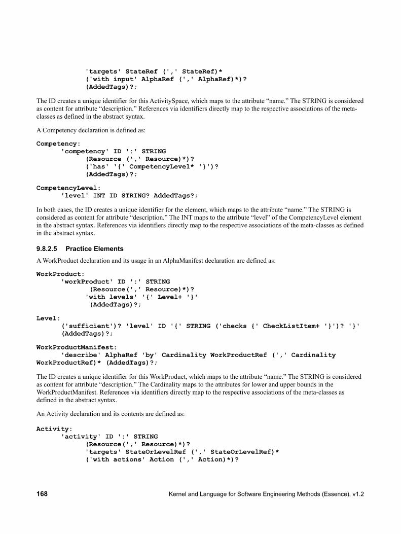
168 Kernel and Language for Software Engineering Methods (Essence), v1.2
'targets' StateRef (',' StateRef)* ('with input' AlphaRef (',' AlphaRef)*)? (AddedTags)?;
The ID creates a unique identifier for this ActivitySpace, which maps to the attribute “name.” The STRING is considered as content for attribute “description.” References via identifiers directly map to the respective associations of the meta-classes as defined in the abstract syntax.
A Competency declaration is defined as:
Competency: 'competency' ID ':' STRING (Resource (',' Resource)*)? ('has' '{' CompetencyLevel* '}')? (AddedTags)?;
CompetencyLevel: 'level' INT ID STRING? AddedTags?;
In both cases, the ID creates a unique identifier for the element, which maps to the attribute “name.” The STRING is considered as content for attribute “description.” The INT maps to the attribute “level” of the CompetencyLevel element in the abstract syntax. References via identifiers directly map to the respective associations of the meta-classes as defined in the abstract syntax.
9.8.2.5 Practice Elements A WorkProduct declaration and its usage in an AlphaManifest declaration are defined as:
WorkProduct: 'workProduct' ID ':' STRING (Resource(',' Resource)*)? 'with levels' '{' Level+ '}' (AddedTags)?;
Level: ('sufficient')? 'level' ID '{' STRING ('checks {' CheckListItem+ '}')? '}' (AddedTags)?;
WorkProductManifest: 'describe' AlphaRef 'by' Cardinality WorkProductRef (',' Cardinality WorkProductRef)* (AddedTags)?;
The ID creates a unique identifier for this WorkProduct, which maps to the attribute “name.” The STRING is considered as content for attribute “description.” The Cardinality maps to the attributes for lower and upper bounds in the WorkProductManifest. References via identifiers directly map to the respective associations of the meta-classes as defined in the abstract syntax.
An Activity declaration and its contents are defined as: Activity: 'activity' ID ':' STRING (Resource(',' Resource)*)? 'targets' StateOrLevelRef (',' StateOrLevelRef)* ('with actions' Action (',' Action)*)?

Kernel and Language for Software Engineering Methods (Essence), v1.2 169
('requires competency level' CompetencyLevelRef(',' CompetencyLevelRef)*)? (AddedTags)?; Action: STRING 'on' (AlphaOrWorkProductRef (',' AlphaOrWorkProductRef)*)?; (AddedTags)?;
The ID creates a unique identifier for this Activity, which maps to the attribute “name.” The STRING on Activity is considered as content for attribute “description.” The STRING on Action is considered as content for attribute “kind.” References via identifiers directly map to the respective associations of the meta-classes as defined in the abstract syntax.
An ActivityAssociation declaration is defined as:
ActivityAssociation: AbstractActivityRef '--' STRING '-->' AbstractActivityRef (AddedTags)?;
The STRING is considered as content for attribute “kind.” References via identifiers directly map to the respective associations of the meta-classes (i.e., “end1” and “end2” in this order) as defined in the abstract syntax.
A Pattern declaration and its contents are defined as:
Pattern: 'pattern' ('<' UserDefinedTypeRef '>')? ID ':' STRING (Resource(',' Resource)*)? ('{' PatternAssociation+ '}')? (AddedTags)?;
PatternAssociation: 'with' PatternElementRef (',' PatternElementRef)* 'as' STRING (AddedTags)?;
The ID on Pattern creates a unique identifier for the element, which maps to the attribute “name.” The STRING is considered as content for attribute “description.” The STRING on PatternAssociation is considered as content for attribute “name.” References via identifiers directly map to the respective associations of the meta-classes as defined in the abstract syntax.
9.8.2.6 Auxiliary Elements A user defined type declaration is defined as:
UserDefinedType: 'type' ID ':' STRING (Resource(',' Resource)*)? ('with constraint' STRING)? (AddedTags)?;
The ID creates a unique identifier for this user defined type, which maps to the attribute “name.” The first STRING is considered as content for attribute “description.” A missing clause with the second STRING is handled as above.
Tags and resources are expressed as:
Tag: (UserDefinedTypeRef '=')? STRING; Resource:

170 Kernel and Language for Software Engineering Methods (Essence), v1.2
'resource' (UserDefinedTypeRef '=')? STRING; AddedTags: 'tagged with' '{' Tag(',' Tag)* '}';
Extension elements and merge resolutions are expressed as:
ExtensionElement: 'on' AnyElementRef 'in' STRING 'apply' STRING (AddedTags)?;
MergeResolution: 'on' STRING 'in' STRING 'apply' STRING (AddedTags)?;
On an ExtensionElement, the STRINGs refer to attributes “targetAttribute” and “extensionFunction” in this order. On a MergeResolution, the STRINGs refer to attributes “targetName”, “targetAttribute” and “ResolutionFunction” in this order.
A Cardinality can be specified according to the following definition:
Cardinality: CardinalityValue ('..' CardinalityValue)? CardinalityValue: INT | 'N'
An identifier used for reference is either a single token or prefixed as following:
ID ('.'ID)*
9.8.3 Examples
A complete Alpha declaration for Kernel Alpha “Requirements”:
alpha Requirements: "What the software system must do to address the opportunity and satisfy the stakeholders." with states { state Conceived {"The need for a new system has been agreed." checks { item checkpoint1 {"The initial set of stakeholders agrees that a system is to be produced."} item checkpoint2 {"The stakeholders that will use and fund the new system are identified."} item checkpoint3 {"The stakeholders agree on the purpose of the new system."} item checkpoint4 {"The expected value of the new system has been agreed."} } } state Bounded {"The purpose and extent of the new system is clear." checks { item checkpoint1 {"Stakeholders involved in developing the new system are identified."} item checkpoint2 {"It is clear what success is for the

Kernel and Language for Software Engineering Methods (Essence), v1.2 171
new system."} item checkpoint3 {"The stakeholders have a shared understanding of the extent of the proposed solution."} item checkpoint4 {"The way the requirements will be described is agreed upon."} item checkpoint5 {"The mechanisms for managing the requirements are in place."} item checkpoint6 {"The prioritization scheme is clear."} item checkpoint7 {"Constraints are identified and considered."} item checkpoint8 {"Assumptions are clearly stated."} } } state Coherent {"The requirements provide a coherent description of the essential characteristics of the new system." checks { item checkpoint1 {"The requirements are captured and shared with the team and the stakeholders."} item checkpoint2 {"The origin of the requirements is clear."} item checkpoint3 {"The rationale behind the requirements is clear."} item checkpoint4 {"Conflicting requirements are identified and attended to."} item checkpoint5 {"The requirements communicate the essential characteristics of the system to be delivered."} item checkpoint6 {"The most important usage scenarios for the system can be explained."} item checkpoint7 {"The priority of the requirements is clear."} item checkpoint8 {"The impact of implementing the requirements is understood."} item checkpoint9 {"The team understands what has to be delivered and agrees that they can deliver it."} } } state Acceptable {"The requirements describe a system that is acceptable to the stakeholders." checks { item checkpoint1 {"The stakeholders accept the requirements as describing an acceptable solution."} item checkpoint2 {"The rate of change to the agreed requirements is relatively low and under control."} item checkpoint3 {"The value provided by implementing the requirements is clear."} item checkpoint4 {"The parts of the opportunity satisfied by the requirements are clear."} item checkpoint5 {"The requirements are testable."} } } state Addressed {"Enough of the requirements have been addressed to satisfy the need for a new system in a way that is acceptable to the

172 Kernel and Language for Software Engineering Methods (Essence), v1.2
stakeholders." checks { item checkpoint1 {"Enough of the requirements are addressed for the resulting system to be acceptable to the stakeholders."} item checkpoint2 {"The stakeholders accept the requirements as accurately reflecting what the system does and does not do."} item checkpoint3 {"The set of requirement items implemented provide clear value to the stakeholders."} item checkpoint4 {"The system implementing the requirements is accepted by the stakeholders as worth making operational."} } } state Fulfilled {"The requirements that have been addressed fully satisfy the need for a new system." checks { item checkpoint1 {"The stakeholders accept the requirements as accurately capturing what they require to fully satisfy the need for a new system."} item checkpoint2 {"There are no outstanding requirement items preventing the system from being accepted as fully satisfying the requirements."} item checkpoint3 {"The system is accepted by the stakeholders as fully satisfying the requirements."} } } }
A minimal declaration of an Activity Space using the Alpha declared above:
activitySpace SpecifyTheSystem: "..." targets Requirements.SufficientlyDescribed
An example for a work product declaration:
workProduct DeveloperTest: "..." with levels { level Sketched {"..."} sufficient level Implemented {"..."} }
An example for an activity declaration:
activity ImplementSolution { targets Implementation.Partial, TestableSystemFeature.Tested with actions "read" on DeveloperTest,SEMAT_Kernel.Requirements, "modify" on SEMAT_Kernel.SoftwareSystem,Implementation }
An example for a practice declaration making use of a practice asset:
practiceAsset ImplementationWork: "..."

Kernel and Language for Software Engineering Methods (Essence), v1.2 173
owns { workProduct Implementation: "..." with levels { level Stubs {"..."} level Partial {"..."} sufficient level Clean {"..."} } } practice TestDrivenDevelopment: "..." with objective "..." owns { alpha TestableSystemFeature: "..." with states { state Planned {"..."} state TestImplemented {"..."} state SolutionImplemented {"..."} state Tested {"..."} } workProduct DeveloperTest: "..." with levels { level Sketched {"..."} sufficient level Implemented {"..."} } workProduct TestLog: "..." with levels { level Raw {"..."} level Analyzed {"..."} } activity ImplementDeveloperTests: "..." targets DeveloperTest.Implemented, TestableSystemFeature.TestImplemented with actions "read" on SEMAT_Kernel.Requirements activity RunDeveloperTests: "..." targets TestableSystemFeature.Tested with actions "read" on DeveloperTest,SEMAT_Kernel.SoftwareSystem, "create" on TestLog activity ImplementSolution: "..." targets ImplementationWork.Implementation.Partial, TestableSystemFeature.Tested with actions "read" on DeveloperTest,SEMAT_Kernel.Requirements, "modify" on SEMAT_Kernel.SoftwareSystem,ImplementationWork.Implementation SEMAT_Kernel.SoftwareSystem contains 1..N TestableSystemFeature describe TestableSystemFeature by 1
174 Kernel and Language for Software Engineering Methods (Essence), v1.2
ImplementationWork.Implementation, 1 DeveloperTest ImplementDeveloperTests -- "part-of" --> SEMAT_Kernel.ImplementTheSystem ImplementSolution -- "part-of" --> SEMAT_Kernel.ImplementTheSystem RunDeveloperTests -- "part-of" --> SEMAT_Kernel.ImplementTheSystem } uses { ImplementationWork }

Kernel and Language for Software Engineering Methods (Essence), v1.2 175
Annex A: Optional Kernel Extensions
(Normative)
A.1 Introduction This annex defines the optional extensions to the Essence Kernel. It presents a number of optional extensions for use with the Software Engineering Kernel. It begins with an introduction of the set of kernel extensions and their use. It then continues with a description of each extension and its contents.
A.1.1 Acknowledgements
Arne-Jørgen Berre, Shihong Huang, Andrey Bayda and Paul McMahon lead the work on the optional Kernel extension.
The following persons contributed valuable ideas and feedback that improved the Kernel extensions: Bob Corrick, Ivar Jacobson, Mira Kajko-Mattsson, Prabhakar R. Karve, Winifred Menezes, Hiroshi Miyazaki, Bob Palank, Tom Rutt and Ian Michael Spence.
A.1.2 Overview
Although the kernel can have many uses, including helping monitor the progress and health of your software engineering endeavors, and the completeness of your software engineering methods, it can appear to be too abstract to actually drive the software development work. This is because the kernel is designed to be used in conjunction with your selected practices. To help you understand how the kernel works, and to provide some extensible assets to help in the creation of your own practices, we present three optional kernel extensions, one for each area of concern. These are the following:
• Business Analysis Extension – adds two Alphas, Need and Stakeholder Representative, to drive forward the Opportunity and the Stakeholders.
• Development Extension – adds two Alphas, Requirement Item and Software System Element to drive forward the Requirements and the Software System. As well as Software System Element it also adds Bug to monitor the health of the Software System. Bugs are an important thing to monitor, track and address in any software development endeavor, and one which will inhibit, rather than drive, progress being made to the Software System.
• Task Management Extension – adds three Alphas, Team Member, Task and Practice Adoption, to drive forward the Team, Work and Way-of-Working.
A.1.3 Why the Focus on Adding Alphas?
When using the kernel it is very unlikely that you will progress any of its Alphas as a single unit. In each case you will drive the progress of the Alpha by progressing its parts. For example the Requirements will be progressed by progressing the individual Requirement Items, each of which can progress at its own speed.
The way in which the Alphas progress is, of course, practice specific. For example agile practices will progress the Requirement Items either individually or in small batches, whereas a waterfall practice will typically try to move them all at the same time.

176 Kernel and Language for Software Engineering Methods (Essence), v1.2
A.1.4 Why are the Subordinate Alphas not included in the Kernel?
When you look at the suggested set of new Alphas you may well think that they themselves are universal and question why they haven’t been included in the kernel.
The problem when looking at software engineering at this level of detail is that the universals tend to be types of things rather than specific things. For example although every endeavor will have Requirement Items, they won’t all have the same type of Requirement Items. Some teams will be using user stories, others will be using use cases, and some even using both. Whilst it is tempting to think that one could provide a definitive definition of a Requirement Item that is satisfactory to all communities and practices, in reality this is an impossibility and would lead to the practices becoming distorted and overly complicated. It is better to provide a generic definition and allow the practice authors to either extend this or ignore it as they wish.
A.1.5 How do you use the Kernel Extensions?
The kernel extensions can be used in a number of different ways:
1. To flesh out the kernel, providing a more complete picture of software engineering.
2. As templates for the creation of your own practices – for example the Requirement Item Alpha could be extended to provide a base for the definition of your own specific types of Requirement Items.
3. As inspiration and examples. By considering the relevant extensions before defining your own practices you will find it easier to create these and understand how they would be plugged into the kernel.
A.2 Business Analysis Extension
A.2.1 Introduction
This extension provides two additional Alphas to help teams to progress their Opportunities and Stakeholders.
A.2.2 Alphas
The business analysis extension extends the customer area of concern adding the following Alphas:
• Stakeholder Representative as a subordinate of Stakeholders.
• Need as a subordinate of Opportunity.
A.2.2.1 Stakeholder Representative
Description Stakeholder Representative: A person, or group, empowered to represent a subset of the stakeholders in the endeavor.

Kernel and Language for Software Engineering Methods (Essence), v1.2 177
Super-Ordinate Alpha
Stakeholders
States Identified The need for a sub-set of the stakeholders to be represented has been
identified. Empowered A stakeholder representative has been empowered to work with the
team and understands his or her responsibilities to the team and the people he or she represents.
Engaged The stakeholder representative is actively involved in the work and fulfilling his or her responsibilities.
Satisfied The stakeholder representative is satisfied with the work done and the software system produced.
Delighted The stakeholder representative is delighted with the work done and the software system produced.
Associations drive : Stakeholders The progress of the Stakeholder Representatives drives the progress
of the Stakeholders.
Justification: Why Stakeholder Representative The number of Stakeholders in any software system is often unbounded, with many systems affecting millions of people. The only practical way to engage with the Stakeholders is to appoint one or more Stakeholder Representatives to gather and reflect the opinions of the actual stakeholders. The Stakeholder Representative may be a single individual representing a sub-set of the stakeholders (or all stakeholders as is the case with the Scrum Product Owner), or some kind of official body such as a focus group or steering committee.

178 Kernel and Language for Software Engineering Methods (Essence), v1.2
Figure A.1 – The states of the Stakeholder Representative
Progressing the Stakeholder Representatives During the development of a software system the stakeholder representatives progress through several state changes. As shown in Figure A.1, they are identified, empowered, engaged, satisfied, and delighted. These states focus on the involvement and satisfaction of the stakeholder representatives, from the identification of a sub-set of the stakeholders that require explicit representation through the empowerment of stakeholder representatives, their engagement in the development work and their satisfaction and delight in the resulting software system. They communicate the progression of the relationship with the stakeholders who are either directly involved in the software engineering endeavor or support it by providing input and feedback.
As indicated in Figure A.1, the first thing to do is to identify which sub-sets of the Stakeholders that require explicit representation in the project and to determine the number of Stakeholder Representatives required. The number of Stakeholder Representatives required can vary considerably from one system to another, but there is always at least one Stakeholder Representative available to the team.
To be effective the Stakeholder Representatives must be empowered both in their relationship with the team and in their relationship with their sub-set of the Stakeholders. Of particular importance is to make sure that they have the time available to support the team and understand the particular needs of the stakeholders they represent. Once they are empowered they need to be engaged with the team and to work with the team so that they are satisfied with the work done and the software system produced. It is key part of their responsibilities to accurately reflect the opinions of the Stakeholders they represent.
Checking the progress of a Stakeholder Representative To help assess the state and progress of a Stakeholder Representative, the following checklists are provided:

Kernel and Language for Software Engineering Methods (Essence), v1.2 179
Table A.1 – Checklist for Stakeholder Representative State Checklist
Identified • A person to act on behalf of the stakeholders has been identified from the stakeholder group.
• The responsibilities of the stakeholder representative have been identified. Empowered • The stakeholder representative has domain knowledge.
• The stakeholder representative has been authorized in decision making.
• The stakeholder representative knows his /her responsibilities. Engaged • The stakeholder representative actively supports the team.
• The stakeholder representative participates in decision making of the product.
• The stakeholder representative provides feedback about the product. Satisfied • The minimum expectation of the stakeholders has been achieved. Delighted • The system meets, or exceeds, the minimum expectation of the stakeholders.
How the Stakeholder Representatives drive the progress of the Stakeholders The progress of the Stakeholders is driven by the Stakeholder Representatives. For illustrative purposes the states of the two Alphas are shown in Figure A.2.
Figure A.2 – The Stakeholder Representatives drive the progress of the Stakeholders
How the Stakeholder Representatives drive the progress of the Stakeholders is summarized in Table A.2, along with the additional checklist items that this kernel extension adds to the Stakeholders’ state checklists.
Identified
Empowered
Stak
ehol
der
Rep
rese
ntat
ive
Delighted
Engaged
Satisfied
Recognized
Represented
Stak
ehol
ders
Satisfied for Deployment
Involved
Satisfied in Use
In Agreement
Drives

180 Kernel and Language for Software Engineering Methods (Essence), v1.2
Table A.2 – How the Stakeholder Representatives drive the Stakeholders Stakeholders State
How the Stakeholder Representatives drive the progress of the Stakeholders
Additional Checklist Items
Recognized First the Stakeholders must be recognized. An important part of this is to identify how they will be represented.
The proposed set of Stakeholder Representatives has been Identified.
Represented Continuing to progress the Stakeholder Representatives will help to continue the progress of the Stakeholders. To ensure that the Stakeholders are represented it is important to make sure that all the identified Stakeholder groups have empowered Stakeholder Representatives.
All the recognized groups of Stakeholders have at least one empowered Stakeholder Representative.
Involved To involve the Stakeholders their Stakeholder Representatives will have to be engaged.
All the recognized groups of Stakeholders have at least one engaged Stakeholder Representative.
In Agreement Actively engaging the Stakeholder Representatives will facilitate bringing them to agreement about the Opportunity to be addressed and the Requirements for the Software System.
Enough of the Stakeholder Representatives are engaged in the decision making for agreement to be reached.
Satisfied for Deployment
The best indication of whether the Stakeholders are satisfied is the level of satisfaction of the individual Stakeholder Representatives. By satisfying the Stakeholder Representatives you can progress the Stakeholders to satisfied for deployment. Note: you may want to engage with more Stakeholder Representatives to verify that the Software System produced for the initial set of Stakeholder Representatives is generally applicable.
All the Stakeholder Representatives are satisfied or delighted with the Software System that has been produced.
Satisfied In Use The best indication of whether the Stakeholders are satisfied is the level of satisfaction of the individual Stakeholder Representatives. By ensuring the continued satisfaction of the Stakeholder Representatives you can progress the Stakeholders to satisfied in use. Again you may want to engage with more Stakeholder Representatives to verify that the Software System produced for the initial set of Stakeholder Representatives is actually useful.
All the Stakeholder Representatives are satisfied or delighted with the Software System that is operational.

Kernel and Language for Software Engineering Methods (Essence), v1.2 181
The state of the individual Stakeholder Representatives is independent of the overall state of the Stakeholders. For example an individual Stakeholder Representative may be engaged before the Stakeholders as a whole are represented.
Note that it is possible that a team may only have one Stakeholder Representative who represents all of the Stakeholders. In this case it is still useful to track the state of the Stakeholder Representative as well as the Stakeholders.
A.2.2.2 Need
Description Need: A lack of something necessary, desirable or useful, requiring supply or relief.
Need exists within the customer, and will be considered by product or portfolio managers who analyze whether there will be value generated by addressing the Need, and pursuing the identified opportunities.
Super-Ordinate Alpha
Opportunity
States Identified A need related to the opportunity and the stakeholders is identified. Value Established The value to the customers and other stakeholders of a successful
solution that addresses the need is established. Satisfied The minimal expectations for a solution that addresses the need have
been met. Expectation Exceeded The minimal expectations for a solution that addresses the need have
been exceeded to the extent that the stakeholders are delighted.
Associations drive : Opportunity The progress of the Needs drive the progress of the Opportunity.
Justification: Why Need Different groups of Stakeholders will respond to the Opportunity in different ways and have different needs for a solution. Explicitly tracking the individual Needs is necessary if you want to truly understand the value of an Opportunity and delight the Stakeholders. Progressing the individual Needs is the best way to ensure that you progress the Opportunity.

182 Kernel and Language for Software Engineering Methods (Essence), v1.2
Figure A.3 – The states of the Need
The Need is necessary for having a well-defined Opportunity, as the Opportunity is the possibility to provide a solution/system that meets the Needs of the Stakeholders.
Progressing the Need If the Team does not take the time to understand the Needs that drive the Opportunity they are likely to identify the wrong Requirements and develop the wrong Software System. The Needs need to be understood and individually addressed. As shown in Figure A.3 Needs progress through the identified, value established, satisfied, and expectations exceeded states. These states focus on understanding the value of addressing the need and the benefit that can be expected from the delivery of an appropriate Software System.
The need is the inherent lack of something necessary, desirable or useful, requiring supply or relief. As indicated in Figure A.3, a Need initially is identified and described in a suitable form. One form it can take is in describing potential features of a new or existing system. Alternatively it can be described in terms of desired outcomes or benefits to be achieved. Once the Need has been identified the next step is to quantify the benefit that could be generated if the Need is addressed. As a next step, the Need’s value gets established, the value to the customers, and other stakeholders. Here, the solution that addresses the Need is quantified and the need has been prioritized.
Finally, when a Software System is available and it fulfills the minimum expectations the Need can progress to the satisfied state. To truly delight the Stakeholders the Software System must surpass the minimal expectation in some way. If this happens then the Need is progressed to the expectations exceeded state.
Checking the progress of Need To help assess the state and progress of Need, the following checklists are provided:

Kernel and Language for Software Engineering Methods (Essence), v1.2 183
Table A.3 – Checklist for Need State Checklist
Identified • A lack of something necessary, desirable or useful to the Stakeholders and related to the Opportunity has been identified.
• The Need has been clearly described.
• It is clear which Stakeholder groups share the Need. Value Established • The value of addressing the Need has been quantified.
• The relative priority of the Need is clear.
• The minimum expectations of the affected Stakeholders are clear. Satisfied • A usable software system that addressed the Need is available.
• The minimum expectations of the affected stakeholders have been satisfied. Expectation Exceeded
• The minimum expectations of the affected stakeholders have been exceeded.
How the Need drives the progress of the Opportunity The need will drive the opportunity by providing the targets for the opportunity to achieve. From a provider point of view the opportunity is the possibility to create a solution that meets the needs of the Stakeholders. The need also provides the foundation for the formulation of the Requirements.
The progress of the Opportunity is driven by the Needs. For illustrative purposes the states of the two Alphas are shown in Figure A.4.
Figure A.4 – The Needs drive the progress of the Opportunity
How the Needs drive the progress of the Opportunity is summarized in Table A.4, along with the additional checklist items that this kernel extension adds to the Opportunity’s state checklists.

184 Kernel and Language for Software Engineering Methods (Essence), v1.2
Table A.4 – How the Needs drive the Opportunity Opportunity State
How the Needs drive the progress of the Opportunity
Additional Checklist Items
Identified First an Opportunity must be identified. Although the Opportunity will be more convincing if some of the Needs that drive it have been identified progress to this state is independent of the state of any of the subordinate Needs.
None.
Solution Needed To demonstrate that a solution is needed analysis if the Opportunity and the Needs that drive it is required. If no compelling Needs are identified then there is no real need for the solution.
At least one compelling Need has been identified.
Value Established To understand the value of the Opportunity one must understand the value of the Needs that drive it. Progressing the Needs to Value Established will help to progress the Opportunity to Value Established.
All of the Needs have been progressed to value established.
Viable Once the value of addressing the Opportunity and its underlying Needs has been established additional work is needed to cost the solution and establish if the Opportunity is viable. No further progress on the Needs is needed at this stage.
None
Addressed Continuing to progress the Needs will help to progress the Opportunity to Addressed. The Opportunity has not been properly addressed in there are critical Needs that have not been satisfied.
All of the critical Needs have been satisfied.
Benefit Accrued It will be difficult for benefit to be accrued from the use of the Software System if it has not satisfied the critical Needs.
It is confirmed by the users that the critical Needs have been satisfied or expectations are exceeded.
Some practices, like goal oriented requirements engineering practices, will introduce the concept of goal as a link from needs and opportunities to system requirements. In such cases a new subordinate alpha of requirements can be introduced for this.
A.3 Development Extensions
A.3.1 Introduction
The Development Extension provides three additional Alphas to help teams to progress the Requirements and Software System alphas.

Kernel and Language for Software Engineering Methods (Essence), v1.2 185
A.3.2 Alphas
The development extension expands the solution area of concern adding the following Alphas:
• Requirement Item as a subordinate of Requirements.
• Bug as a subordinate of Software System.
• Software System Element as a subordinate of Software System.
A.3.2.1 Requirement Item
Description Requirement Item: a condition or capability needed by a stakeholder to solve a problem or achieve an objective.
Requirements are composed of Requirement Items. These are the individual requirements, which can be addressed and progressed individually. The overall progress and health of the Requirements alpha is driven by the progress and health of its Requirement Items. The number of Requirement Items can vary in a wide range from one system to another.
Super-Ordinate Alpha Requirements
States Identified A specific condition or capability that the Software System must
address has been identified. Described The Requirement Item is ready to be implemented. Implemented The Requirement Item is implemented in the Software System and
demonstrated to work. Verified Successful implementation of the Requirement Item in the Software
System has been confirmed.

186 Kernel and Language for Software Engineering Methods (Essence), v1.2
Figure A.5 – The states of Requirement Item
Associations drive : Requirements The progress of the Requirement Items drives the progress of the
Requirements.
Justification: Why Requirement Item The Software System is usually developed to fulfill a number (a potentially very high number) of Requirements. The only efficient way to manage them is to manage them individually (e.g., as Requirement Items) while being aware of their progress as a whole. Managing requirements at the Requirement Item level allows teams to ensure that the Requirements are appropriately crafted (i.e., they are necessary, implementation independent, clear and concise, complete, consistent, achievable, traceable and verifiable). It also helps when mapping them to the code and tests, and when using any form of requirements management tool.
Progressing the Requirement Items During the development of a software system the requirement items progress through several state changes. As shown in Figure A.5, they are identified, described, implemented, and verified. These states focus on the progress and health of the individual Requirement Items, from their identification and description as part of the requirements elicitation to their implementation and verification by the development team. Understanding the state of the Requirement Items helps in planning, tracking and driving the development of the required Software System.
The individual Requirement Items are first identified. This may be as the result of a requirements workshop, receiving a change request, or even derived from another higher-level Requirement Item. In the first state of the Requirement Item, the identified state, a specific condition or capability that the Software System must address has been identified. Its objectives have been briefly defined and its management mechanism is selected. Work is then needed to flesh out the Requirement Item and ensure that it is well formed and suitably described.
In the described state, the description of the Requirement Item evolves into a clear, concise, complete, consistent, and verifiable description. The Requirement Item is also justified as necessary and achievable, and prioritized relative to its
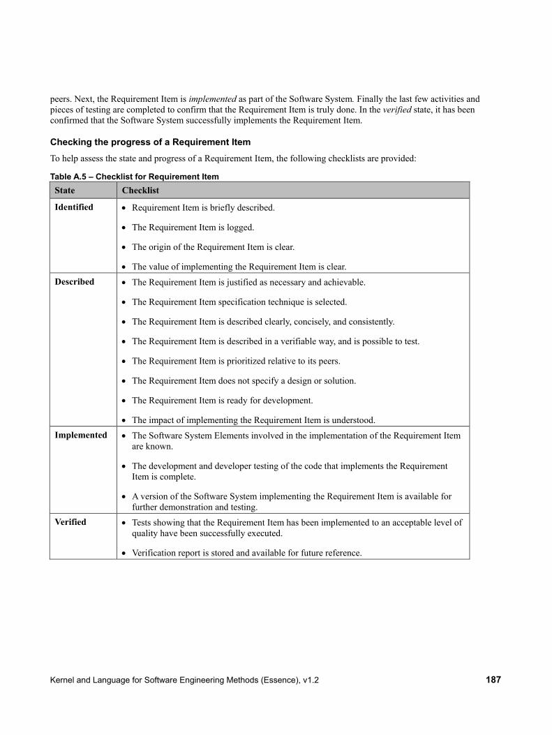
Kernel and Language for Software Engineering Methods (Essence), v1.2 187
peers. Next, the Requirement Item is implemented as part of the Software System. Finally the last few activities and pieces of testing are completed to confirm that the Requirement Item is truly done. In the verified state, it has been confirmed that the Software System successfully implements the Requirement Item.
Checking the progress of a Requirement Item To help assess the state and progress of a Requirement Item, the following checklists are provided:
Table A.5 – Checklist for Requirement Item State Checklist
Identified • Requirement Item is briefly described.
• The Requirement Item is logged.
• The origin of the Requirement Item is clear.
• The value of implementing the Requirement Item is clear. Described • The Requirement Item is justified as necessary and achievable.
• The Requirement Item specification technique is selected.
• The Requirement Item is described clearly, concisely, and consistently.
• The Requirement Item is described in a verifiable way, and is possible to test.
• The Requirement Item is prioritized relative to its peers.
• The Requirement Item does not specify a design or solution.
• The Requirement Item is ready for development.
• The impact of implementing the Requirement Item is understood. Implemented • The Software System Elements involved in the implementation of the Requirement Item
are known.
• The development and developer testing of the code that implements the Requirement Item is complete.
• A version of the Software System implementing the Requirement Item is available for further demonstration and testing.
Verified • Tests showing that the Requirement Item has been implemented to an acceptable level of quality have been successfully executed.
• Verification report is stored and available for future reference.

188 Kernel and Language for Software Engineering Methods (Essence), v1.2
Figure A.6 – The Requirement Items drive the progress of the Requirements
How the Requirement Items drive the progress of the Requirements The progress of the Requirements is driven by the associated Requirement Items. For illustrative purposes the states of the two Alphas are shown in Figure A.6.
How the Requirement Items drive the progress of the Requirements is summarized in Table A.6, along with the additional checklist items that this kernel extension adds to the Requirements state checklists.
Table A.6 – How the Requirement Items drive the Requirements Requirements State
How the Requirement Items drive the progress of the Requirements
Additional Checklist Items
Conceived Progress to the conceived state is independent of the state of any of the subordinate Requirement Items.
None
Bounded To properly bound the Requirements some of the most important Requirement Items should be identified and described.
One or more essential Requirement Items have been identified and described.

Kernel and Language for Software Engineering Methods (Essence), v1.2 189
Requirements State
How the Requirement Items drive the progress of the Requirements
Additional Checklist Items
Coherent Continuing to progress the Requirement Items will help to continue the progress of the Requirements. Describing the Requirement Items that communicate the essential characteristics of the system will help the Requirements to become coherent.
New complete checklist:
• The Requirement Items have been iden-tified and shared with the team and the stakeholders.
• The Requirement Items that communi-cate the essential characteristics of the system have been described.
• Conflicting Requirement Items have been identified and attended to.
• The described Requirement Items communicate the essential characteris-tics of the system to be delivered.
• The most important usage scenarios for the system can be explained.
• The team understands what has to be delivered and agrees to deliver it.
Acceptable Describing the highest priority Requirement Items will help evolve the Requirements to the point where they define a system acceptable to the stakeholders. Note: For mature systems this may only require the definition of a single Requirement Item – what makes the Requirements acceptable is up to the Stakeholders.
New complete checklist:
• Enough Requirement Items are de-scribed to define a system acceptable to the stakeholders.
• The rate of change to the agreed Re-quirement Items is relatively low and under control.
• The Needs satisfied by the Require-ment Items are clear.

190 Kernel and Language for Software Engineering Methods (Essence), v1.2
Requirements State
How the Requirement Items drive the progress of the Requirements
Additional Checklist Items
Addressed Implementing and verifying the Requirement Items is the only way to address the Requirements. The Requirements are addressed when the set of Requirement Items implemented and verified provide clear value to the stakeholders and the resulting system is worth releasing.
New complete checklist:
• Enough of the Requirement Items have been Implemented and Verified for the resulting system to be acceptable to the stakeholders.
• The stakeholders accept the Require-ment Items as accurately reflecting what the system does and does not do.
• The set of Requirement Items imple-mented and verified provide clear value to the stakeholders.
• The system implementing the Require-ment Items is accepted be the stake-holders as worth making operational.
Fulfilled You continue implementing and verifying additional requirement items until the resulting system fully satisfies the need for a new system, and there are no outstanding Requirement Items preventing the system from being considered complete.
Requirements checklist item “There are no outstanding requirement items preventing the system from being accepted as fully satisfying the requirements” is replaced with the following item: “All Requirement Items preventing the system from being accepted as fully satisfying the requirements have been verified.”
The state of the individual Requirement Items is independent of the states of their owning Requirements. It is quite possible for one or more Requirement Items to be verified before the Requirements are bounded or coherent. For example you could implement and verify some of the most obvious, important and risky requirement items before investing the time and effort in working with the Stakeholders to make the Requirements bounded or coherent.
A.3.2.2 Bug
Description Bug: An error, flaw, or fault in a Software System that causes the system to fail to perform as required.
Super-Ordinate Alpha Software System
States Detected An error, fault or flaw in the Software System is observed and logged. Located The cause of the Bug in the Software System has been found. Fixed The Bug has been removed from the Software System. Closed The removal of the Bug from the Software System has been
confirmed.

Kernel and Language for Software Engineering Methods (Essence), v1.2 191
Associations inhibit : Software System The Bugs inhibit the progress of the Software System.
Justification: Why Bug Bugs are inevitable part of software development. The trick is to eliminate them all before the Software System is operational. The overall state of the Software System is affected by the quantity and severity of the Bugs it contains. Understanding and monitoring the progress and health of any Bugs detected is an essential part of any software engineering endeavor.
Essence uses the term Bug as it is one of the most common words in the software industry, and is more intuitive and less open to misinterpretation than the other alternatives such as problem and defect.
Figure A.7 – The states of a Bug
Progressing the Bugs Bugs threaten the success of any software engineering endeavor. They have to be found and resolved before they cause any damage. As shown in Figure A.7, Bugs progress through the detected, located, fixed and closed states. These states focus on the management of the Bugs and provide clear understanding of whether they are inhibiting the progress of, or threatening the health of, the Software System.
The Bug first has to be detected. This may be as the result of testing, reviewing or using the Software System. Once a Bug is detected it is reported and logged. Then the Bug must be investigated and its cause must be located. If the cause of the bug cannot be identified then it will be impossible to fix. Once the Bug is located it can be fixed and a new bug-free version of the Software System can be made available. Finally, after the Team has confirmed its absence in the updated Software System, the Bug is closed.
Checking the progress of a Bug To help assess the state and progress of a Bug, the following checklists are provided:

192 Kernel and Language for Software Engineering Methods (Essence), v1.2
Table A.7 – Checklist for Bug State Checklist
Detected Bug has been reported and given a unique identifier.
• Details about the Bug, and the situation within which it occurred, have been reported.
• The severity of the Bug has been assessed. Located The Bug has been investigated and its impact assessed.
• The Software System Elements causing the Bug have been identified.
• The cost of fixing and testing the Bug has been estimated.
• The Bug is ready to be fixed. Fixed The work required to correct the offending Software System Elements has been completed.
• A new Bug-free version of the Software System is available.
• The absence of the Bug has been verified. Closed Tests, reviews or other appropriate activities have been undertaken to ensure that the Bug has
been corrected or shown not to actually be an error, fault or flaw.
• The Bug management has been finalized.
Figure A.8 – The Bugs inhibit the progress of the Software System
How the Bugs inhibit the progress of the Software System The progress of the Software System is inhibited by the Bugs found in it. For illustrative purposes the states of the two Alphas are shown in Figure A.8.

Kernel and Language for Software Engineering Methods (Essence), v1.2 193
How the Bugs inhibit the progress of the Software System is summarized in Table A.8, along with the additional checklist items that this kernel extension adds to the Software System state checklists.
Table A.8 – How the Bugs inhibit the Software System Software System State
How the Bugs drive the progress of the Software System
Additional Checklist Items
Architecture Selected Progress to this state is independent of the state of any of Bugs in the Software System.
None
Demonstrable When the Software System is in demonstrable state some bugs may be detected and located.
The Bugs detected and/or located did not prevent the Software System from being successfully demonstrated.
Usable Detecting and fixing Bugs will help to continue the progress of the Software System. Fixing any Bugs in the core functionality of the Software System is essential for it to become usable.
All critical Bugs have been fixed.
Ready Detecting and fixing Bugs will help evolve the Software System to the point where it is ready for deployment in a live environment.
The number and severity of the Bugs yet to be Fixed and Closed are low enough so that the system can be deployed.
Operational Fixing any Bugs detected during live use of the Software System is an important part of keeping it operational.
The remaining Bugs, if any, do not require immediate fixing.
Retired The system is no longer being supported
None
The state of the individual Bugs are independent of the states of their owning Software System. It is quite possible for one or more Bugs to be Detected or Located after the Software System is Ready or Operational. For example using the system which contains some non-critical Bugs may be beneficial enough for deploying and using it before these Bugs are closed.
A.3.2.3 Software System Element
Description Software System Element: Independently developable and testable part of a system.
Software System Elements are the independent but interrelated parts that together comprise a Software System. Hence, the Software System’s progress and health are driven by the progress and health of its Software System Elements.
Super-Ordinate Alpha Software System
States Identified A system element has been identified as part of the Software System

194 Kernel and Language for Software Engineering Methods (Essence), v1.2
and its responsibilities and its position in the Software System are clear.
Interfaces Agreed The Software System Elements interfaces have been agreed. Developed The Software System Element has been implemented and tested, and
is believed to be ready for integration into the Software System. Ready The Software System Element has been verified and is ready for live
use as part of the Software System.
Associations drive : Software System The progress of the Software System Elements drives the progress of
the Software System.
Justification: Why Software System Element A Software System is made up of software, hardware, and data. Each part of the Software System can be software or hardware or data or any combination of the three. A Software System usually consists of several parts or System
Figure A.9 – The states of Software System Element
Element
s in Essence terms. Essence recognizes universal states that all system elements progress through during the development of a Software System.

Kernel and Language for Software Engineering Methods (Essence), v1.2 195
Progressing the Software System Elements A Software System is not usually developed as a single solid block. It is built from a number of Software System Elements, each of which may be specially built or acquired from elsewhere. During their development Software System Elements progress through several state changes. As shown in Figure A.9, they are identified, interfaces defined, developed, and ready. These states focus on providing clear understanding of Software System Element states.
As indicated in Figure A.9, the first thing to do is to identify Software System Elements needed and assign them their responsibilities within the overall Software System. Once the Software System Element is identified its expected behavior and position in the Software System is known and the decision can be made about how to source it. The next step is to refine the Software System Element’s responsibilities and make sure its interfaces are agreed. When the Software System Element interfaces are agreed its relationship with the other Software System Elements, and where necessary other systems, are defined. The Team can now complete the implementation and testing of the Software System Element progressing it to the developed state. Finally, after all the required testing is done, the Software System Element is ready for live use as part of the Software System.
Checking the progress of a Software System Element To help assess the state and progress of a Software System Element, the following checklists are provided:
Table A.9 – Checklist for Software System Element State Checklist
Identified • The need for the Software System Element is recognized.
• The Software System Element’s expected behavior and responsibilities in the Software System are clear.
• Any additional Software Systems that need this Software System Element are identified.
• The options about whether to buy or build the Software System Element have been explored.
• Any requirements and constraints on the Software System Element are known, such as performance requirements or memory utilization constraints.
Interfaces Agreed • Interfaces of the Software System Element with the other system elements are defined.
• Required interfaces of the Software System Element with other systems are defined.
• Buy or build decisions have been made.
• It has been specified how other Software System Elements should interact with the Software System Element.
• All externally detectable outcomes are specified including data that is returned and events that may be raised.
Developed • The Software System Element has been implemented in a way that is conformant with its interfaces.
• The Software System Element implements the operations on its provided

196 Kernel and Language for Software Engineering Methods (Essence), v1.2
State Checklist interfaces.
• The Software System Element has been verified as conformant with its interfaces by passing all its unit tests.
• The Software System Element is available for integration into the Software System. Ready • All the required testing on the Software System Element is complete.
• The Software System Element can interoperate with the other Software System Elements in the System.
• The Software System Element can interoperate with any external systems it communicates with.
• Software System Element is available for use in the live environment.
Figure A.10 – The Software System Elements drive the progress of the Software System
How the Software System Elements drive the progress of the Software System The progress of the Software System is driven by the system elements composing it. For illustrative purposes the states of the two Alphas are shown in Figure A.10.
How the Software System Elements drive the progress of the Software System is summarized in Table A.10, along with the additional checklist items that this kernel extension adds to the Software System state checklists.

Kernel and Language for Software Engineering Methods (Essence), v1.2 197
Table A.10 – How the Software System Elements drive the Software System Software System State
How the Software System Elements drive the progress of the Software System
Additional Checklist Items
Architecture Selected
To progress the Software System to the architecture selected state the Software System Elements that make up the Software System should be identified and have their Responsibilities Assigned. The core Software System Elements should also have their interfaces agreed.
The core Software System Elements are all in the interfaces agreed state.
Demonstrable The core Software System Elements need to be acquired or developed to be able to assemble a demonstrable Software System.
The core Software System Elements are all developed and included in the Software System
Usable Making ready the Software System Elements that implement the essential characteristics of the system will help the whole system to become usable.
The Software System Elements that implement the essential characteristics of the system have been made ready.
Ready Continuing to progress the Software System Elements will help to continue the progress of the Software System. For the Software System to be ready all of its parts must also be ready.
All of the Software System Elements that make up the system are ready.
Operational All the Software System Elements should remain ready to make, and keep, the Software System operational.
All of the Software System Elements that make up the system are Ready.
Retired Progress to the retired state is independent of the state of any of the subordinate Software System Elements.
None
The state of the individual Software System Elements is independent of the state of their owning Software System. It is quite possible for the Software System Elements to change states between interfaces defined and developed in both forward and backward directions to reflect the need for their further development and maturation. When Software System Element reaches ready state its correct interoperability with other Software System Elements and Systems is confirmed. In many cases once a Software System Element achieves the ready state any additional changes are only allowed if the state is maintained.
A.4 Task Management Extension
A.4.1 Introduction
The Task management extension provides three additional Alphas to allow teams to progress their Team, Work and Way of Working.

198 Kernel and Language for Software Engineering Methods (Essence), v1.2
A.4.2 Alphas
The task management extension enhances the endeavor area of concern adding the following Alphas:
• Team Member as a subordinate of Team
• Task as a subordinate of Work
• Practice Adoption as a subordinate of Way of Working
A.4.2.1 Team Member
Description Team Member: An individual working as part of a team.
The Team Members are a group of people that comprise a team.
Super Ordinate Alpha Team
States Wanted A team member with specific skills is sought to join the team. On Board The team member is on board and learning how to contribute to the
team. Contributing The team member is helping her teammates and driving the team's
performance Exiting The team member is preparing to leave the team.
Associations drive : Team The progress of the Team Members drives the progress of the Team.
Justification: Why Team Member Team Members are needed to form a Team. A Team may range from two to many Team Members. This means that Teams have at least two Team Members.
Progressing the Team Members Team Members progress through a number of states. As indicated in Figure A.11, these are wanted, on-board, contributing, and exiting. These states focus on how well the Team Members are integrated into the team.

Kernel and Language for Software Engineering Methods (Essence), v1.2 199
Figure A.11 – The states of Team Member
First it must be decided that a new team member is wanted. In this state the competencies and skills that are required are identified and steps are being taken to find a new Team Member. Once a new team member has been found she needs to be brought on board. This means that the Team Member has been selected and inducted into the team, and is ready to learn how to fulfill her responsibilities and overcome any challenges presented by the new role. Over time she becomes a contributing member of the team implying that she is actively fulfilling her responsibilities and helping to drive the team's performance.
When a team member decides to leave the team, or is no longer needed by the team, she is considered to be exiting and is transitioned out of the team.
Checking the progress of a Team Member To help assess the state and progress of a Team Member, the following checklists are provided:
Table A.11 – Checklist for Team member State Checklist
Wanted • The required competencies and skills for a role have been identified.
• An individual with required competencies and skills is being sought.
On Board • Team member has been inducted into the team.
• Team member is learning how to contribute to the work and participate on the team.
• The gap, if any, between the Team member’s actual skills and competencies and those required by their new role are known.
Contributing • The Team member is collaborating effectively with teammates.
• The Team member actively contributes to the team.

200 Kernel and Language for Software Engineering Methods (Essence), v1.2
State Checklist
Exiting • The Team member’s participation on the team is coming to an end.
• The Team member has completed or is handing over her responsibilities to someone else.
Figure A.12 – The Team Members drive the progress of the Team
How the Team Members drive the progress of the Team The progress of the Team is driven by the associated Team Members. For illustrative purposes the states of the two Alphas are shown in Figure A.12.
How the Team Member Alpha drives the progress of the Team Alpha is summarized in Table A.12, along with the reference to additional checklist items that this kernel extension adds to the Team state checklists.

Kernel and Language for Software Engineering Methods (Essence), v1.2 201
Table A.12 – How the Team Members drive the Team Team State How the Team Members drive the
progress of the Team Additional Checklist Items
Seeded One or more of the expected Team Members are needed to seed the Team.
One or more key Team Members are on board. One or more additional Team Members are wanted.
Formed The remaining Team Members are recruited to form the team.
All required team members are on board.
Collaborating As the Team members start to work together they drive the team to the collaborating state.
The majority of the team members are actively contributing to the success of the team.
Performing As the Team Members start to work well together and continuously improve their team working they drive the team to the performing state.
All team members are actively contributing to the success of the team.
Adjourned Finally, when the team is no longer needed it is adjourned.
All team members have exited the team.
The state of the individual Team Members is independent of the states of their owning Team. It is quite possible for one or more Team Members to be contributing before the Team is collaborating or performing. For example you might have some Team Members that are on-board but are still being brought up to speed, while others are fully contributing.
A.4.2.2 Task
Description Task: A portion of work that can be clearly identified, isolated, and then accepted by one or more team members for completion.
Super Ordinate Alpha Work
States Identified The task has been identified and is ready to be done. In Progress The task has been accepted by one or more team members and work
has started. Done The work required to do the task has been completed.
Associations drive : Work The progress of the Tasks drives the progress of the Work.
Justification: Why Task Tasks are the fundamental unit of work that team members use to identify and track their work progress.

202 Kernel and Language for Software Engineering Methods (Essence), v1.2
Progressing the Tasks Tasks pass through a number of states. As indicated in Figure A.13, these are identified, in progress, and done. These states focus on the management of the Task. Tracking the progress of the tasks is important for monitoring the work.
Tasks are first identified by looking at the Work that needs to be done. Tasks correspond to pieces of work that are easily isolated from the work, small enough to be estimated by the team, and easily manageable to be implemented by one or several team members. A single task may concern different levels of difficulty and effort required. It could concern development of multiple work products, or multiple tasks could concern completion of a single work product. The granularity of a task is proportional to the trust you have in your team members based on previous work experience.
Once work starts on a Task it progresses to the in progress state during which time there is at least one team member actively working on it. Finally a task is done when the work required to do the task has been completed. This may be because it has been determined to be completed according to the agreed to completion criteria.
Figure A.13 – The states of the Task
Checking the progress of a Task To help assess the state and progress of a Task, the following checklists are provided:

Kernel and Language for Software Engineering Methods (Essence), v1.2 203
Table A.13 – Checklist for Task State Checklist
Identified • A portion of work has been clearly identified, isolated and named as a task.
• The objective of the task is clear.
• The activities that need to be done have been clearly described.
• It is clear whether the task is a full team task, group task or individual task.
• The completion criteria for the task are clearly defined.
• The effort required to complete the task has been estimated and agreed. In Progress • A team member has accepted and is progressing the task.
• The progress of the task is monitored.
• A target completion date for the task has been agreed.
• The amount of effort required to complete the task is being tracked. Done • The task is determined to be complete according to its agreed to completion criteria.
Figure A.14 – The Tasks drive the progress of the Work

204 Kernel and Language for Software Engineering Methods (Essence), v1.2
How the Tasks drive the progress of the Work The progress of the Work is driven by the associated Tasks. For illustrative purposes the states of the two Alphas are shown in Figure A.14.
How the Task Alpha drives the progress of the Work Alpha is summarized in Table A.14, along with the reference to additional checklist items that this kernel extension adds to the Work state checklists.
Table A.14 – How the Tasks drive the progress of the Work Work State How the Task drive the progress of the
Work Additional Checklist Items
Initiated The Tasks needed to prepare the Work are identified as part of the activity to initiate the work.
Tasks to be undertaken to prepare the work have been identified.
Prepared Tasks are identified as part of the activity to prepare the work and all are in the done state.
The Tasks to be undertaken to prepare the Work are Done. Enough Tasks have been Identified for the Team to start the real Work.
Started As Tasks move to the in progress state the work gets started.
At least one task has been initiated by one or several team members
Under control After sufficient tasks are completed work reaches the under control state.
All team members are effectively working on their tasks
Concluded When all tasks are done the work is concluded.
All identified tasks have been done
Closed None None The state of the individual Tasks are independent of the state of the overall Work. For example, it is quite possible for one or more Tasks to be in progress, or even done, before the Work is under control.
A.4.2.3 Practice Adoption
Description Practice Adoption: The adoption of a practice over time and its supporting tooling as part of a team's way of working.
Super-Ordinate Alpha Way of Working
States Selected The practice is selected. Integrated The practice and related tools have been integrated into the way of
working and are ready for use. In Use Team members are using the practice and related tools to accomplish
their work. Working well The adopted practice is working well for the team members.

Kernel and Language for Software Engineering Methods (Essence), v1.2 205
Associations drive : Way of Working The progress of the Practice Adoptions drive the progress of the Way
of Working
Figure A.15 – The states of Practice Adoption
Figure A.16 – Practice Adoption drive the progress of the Way of Working

206 Kernel and Language for Software Engineering Methods (Essence), v1.2
Justification: Why Practice Adoption Teams improve their way of working by adopting and adapting individual practices. Even teams with the simplest way of working have at least one practice.
Progressing the Practice Adoptions Practice Adoption undergoes a number of states. As indicated in Figure A.15, these states are selected, integrated, In Use, and working well. These states focus on the progression of practice adoption as the practices are integrated with tools and other practices. Practice use by the team and their evolution towards working well help team members collaborate and complete their tasks effectively.
Checking the progress of a Practice Adoption To help assess the state and progress of a Practice Adoption, the following checklists are provided:
Table A.15 – Checklist for Practice Adoption State Checklist
Selected • The practice and related tools have been selected. Integrated • The practice has been tailored to meet the constraints of the work environment.
• The related tools have been integrated to work together with the selected practice and other selected tools.
• The team members who will use this practice have received the necessary training, if needed.
In Use • The tailored practice is being used by team members to perform their work.
• The tools that have been selected for integration with the practices are being used by the team members.
Working well
• All team members are making progress as planned by using the tailored practice.
• All team members naturally apply the tailored practice without thinking about it.
• The practice and tools are used routinely and effectively by the team.
• The practice and tools are regularly being inspected and improved by the team.
How Practice Adoption drives the progress of Way of Working The progress of the Way of Working is driven by the associated Practice Adoptions. For illustrative purposes the states of the two Alphas are shown in Figure A.16.
How the Practice Adoption Alpha drives the progress of the Way of Working Alpha is summarized in Table A.16, along with the reference to additional checklist items that this kernel extension adds to the Way of Working state checklists.

Kernel and Language for Software Engineering Methods (Essence), v1.2 207
Table A.16 – How the Practice Adoption Alpha drives the Way of Work Alpha Way of Working State
How the practice adoption drives the progress of the Way of Work
Additional Checklist Items
Principles Established
At least one Practice has been selected in support of the established principles.
At least one Practice has been selected that supports the established principles.
Foundation Established
As each practice and related tools are selected and integrated the Way of Working foundation is established.
At least two practices have been selected and integrated.
In Use Once the foundation is established, the practices and tools are used by team members as part of their way of working.
A sufficient number of practices and tools have been selected and integrated to support some of the team member's needs.
In Place The Way of Working is in place when the selected and integrated practices and tools are used by all relevant team members.
A sufficient number of practices have been integrated to support the team member's needs, At least some of the practices and tools are working well for the team.
Working Well As the practices help team members effectively complete their work the way of working reaches a working well state.
All the required practices have been integrated and are supporting all team member's needs.
Retired None None
The state of the individual Practice Adoption is independent of the state of the overall Way of Working. For example, one or more Practices may be in use, or even working well, before the Way of Working is working well for the Team.

208 Kernel and Language for Software Engineering Methods (Essence), v1.2
This page intentionally left blank.

Kernel and Language for Software Engineering Methods (Essence), v1.2 209
Annex B: KUALI-BEH Kernel Extension
(Informative)
B.1 Introduction This annex defines the example KUALI-BEH2 extension to the Essence Kernel. The KUALI-BEH extension provides four additional Alphas to allow teams to express their Way of Working and the progress of their Work in software projects.
B.1.1 Acknowledgements
Hanna J. Oktaba and Miguel Ehécatl Morales Trujillo lead the work on the KUALI-BEH Kernel extension, which was based on the KUALI-BEH 1.1 revised submission guided by Hanna J. Oktaba. and Miguel Ehécatl Morales Trujillo, and on the KUALI-BEH 1.0 initial submission with participation of Magdalena Dávila Muñoz.
The following persons contributed valuable ideas and feedback that improved the KUALI-BEH extension: Mario Piattini Velthuis, Francisco Hernández Quiroz, María Guadalupe Ibargüengoitia González, Jorge Barrón Machado, María Teresa Ventura Miranda, Liliana Rangel Cano, Nubia Fernández, María de los Ángeles Sánchez Zarazua, Luis Daniel Barajas González, Sergio Eduardo Muñoz Siller, Elliot Iván Armenta Villegas, María de los Ángeles Ramírez, Miguel Ángel Peralta Martínez, José León González, Rodrigo Barrera Hernández, José Luis Urrutia Velázquez, Eraim Ruíz Sánchez, Álvaro Antonio Saldaña Nava, Alberto Tapia, Hugo Rojas Martínez, Evaristo Fernández Perea and Octavio Orozco y Orozco.
B.2 Alphas
B.2.1 Overview
The KUALI-BEH extension amplifies the endeavor area of concern adding the following Alphas:
• Practice Authoring as a subordinate alpha of Way of Working
• Method Authoring as a subordinate alpha of Way of Working
• Practice Instance as a subordinate alpha of Work
• Method Enactment as a subordinate alpha of Work
The Practice Authoring Alpha allows the practitioners to express work units as practices. These practices can be composed as methods by the Method Authoring Alpha. Practice and Method Authoring Alphas help to articulate explicitly the practitioners’ Way of Working.
The Way of Working defined as practices and/or methods is executed by the organization practitioners and converted into units of Work using the Practice Instance Alpha. As a set, these practice instances define the Method Enactment that can be tracked and its progress checked.
2 KUALI: Nahuatl word meaning good, fine or appropriate. BEH: Mayan word meaning way, course or path.
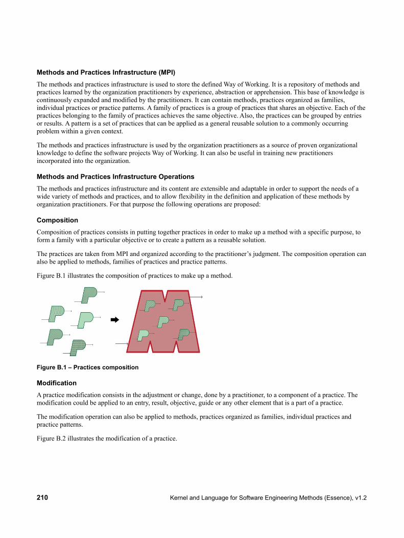
210 Kernel and Language for Software Engineering Methods (Essence), v1.2
Methods and Practices Infrastructure (MPI) The methods and practices infrastructure is used to store the defined Way of Working. It is a repository of methods and practices learned by the organization practitioners by experience, abstraction or apprehension. This base of knowledge is continuously expanded and modified by the practitioners. It can contain methods, practices organized as families, individual practices or practice patterns. A family of practices is a group of practices that shares an objective. Each of the practices belonging to the family of practices achieves the same objective. Also, the practices can be grouped by entries or results. A pattern is a set of practices that can be applied as a general reusable solution to a commonly occurring problem within a given context.
The methods and practices infrastructure is used by the organization practitioners as a source of proven organizational knowledge to define the software projects Way of Working. It can also be useful in training new practitioners incorporated into the organization.
Methods and Practices Infrastructure Operations The methods and practices infrastructure and its content are extensible and adaptable in order to support the needs of a wide variety of methods and practices, and to allow flexibility in the definition and application of these methods by organization practitioners. For that purpose the following operations are proposed:
Composition Composition of practices consists in putting together practices in order to make up a method with a specific purpose, to form a family with a particular objective or to create a pattern as a reusable solution.
The practices are taken from MPI and organized according to the practitioner’s judgment. The composition operation can also be applied to methods, families of practices and practice patterns.
Figure B.1 illustrates the composition of practices to make up a method.
Figure B.1 – Practices composition
Modification A practice modification consists in the adjustment or change, done by a practitioner, to a component of a practice. The modification could be applied to an entry, result, objective, guide or any other element that is a part of a practice.
The modification operation can also be applied to methods, practices organized as families, individual practices and practice patterns.
Figure B.2 illustrates the modification of a practice.

Kernel and Language for Software Engineering Methods (Essence), v1.2 211
Figure B.2 – Practice modification
B.2.2 Practice Authoring
Description Practice Authoring: It is the defined work guidance, with a specific objective, that advises how to produce a result originated from an entry. The guide provides a systematic and repeatable set of activities focused on the achievement of the practice objective and result. The completion criteria associated to the result are used to determine if the objective is achieved. Particular competences are required to perform the practice guide activities, which can be carried out optionally using tools. To evaluate the practice performance and the objectives’ achievement, selected measures can be associated to it. Measures are estimated and collected during the practice execution.
The practice authoring provides a framework for the definition of the practitioners’ different ways of working. This knowledge makes up an infrastructure of methods and practices that is defined and applied by practitioners in the organization.
Super-Ordinate Alpha Way of Working
Other related Alpha Method Authoring
States Identified The way of working to be authored as a practice is identified by the
practitioners. Expressed The way of working is expressed as a practice using the practice template. Agreed The practice is agreed on by the practitioners. In Use The practice is used in software projects by the practitioners as their way
of working. In Optimization The practice is adapted and/or improved by the practitioners based on their
experience, knowledge and external influence. Consolidated The practice is mature and adopted by the practitioners as a routine way of
working.
Associations expresses : Way of Working The Practice Authoring lets the practitioners express their Way of
Working.
composes: Method Authoring The authored practices can compose a method.

212 Kernel and Language for Software Engineering Methods (Essence), v1.2
Figure B.3 – The states of Practice Authoring
Justification: Why Practice Authoring Software Engineering practitioners have an implicit way of working which is constantly improving. By authoring individual practices they can express them explicitly. Even practitioners with the simplest way of working follow tacit practices.
Conceptualizing the Practice Authoring In order to express and define the way of working of practitioners, Practice Authoring has the following related concepts:
• Objective: Short statement that describes the goal that the practice pursues.
• Entry: Expected characteristics of a work product and/or conditions and/or Alpha states needed to start the execution of a practice.
• Result: Expected characteristics of a work product and/or conditions and/or Alpha states required as outputs after the execution of a practice.
• Guide: Set of recommended activities aimed to resolve a specific objective transforming an entry into a result. Particular competences are needed to perform the advised activities. The same practice may be carried out following different guides, but they should accomplish the practice objective and preserve their entry and result characteristics. The tools to support the guide activities could be described optionally.
• Activity: Set of tasks that contribute to the achievement of a practice objective.
Expressed
Agreed
In Use
In Optimization
Consolidated
Prac
tice
Auth
orin
g The way of working is expressed as a practice using the practice template.
The practice is agreed on by the practitioners.
The practice is used in software projects by the practitioners as their way of working.
The practice is adapted and/or improved by the practitioners based on their experience, knowledge and external influence.
The practice is mature and adopted by the practitioners as a routine way of working.
IdentifiedThe way of working to be authored as a practice is identified by the practitioners.

Kernel and Language for Software Engineering Methods (Essence), v1.2 213
• Task: Requirement, recommendation or permissible action.
• Measures: List of standard units used to evaluate the practice performance and the objectives’ achievement.
• Completion Criteria: Set of criteria that can be tested as true or false that contributes to the determination of whether a practice is complete. The completion criteria, derived from the activities, are used to verify if the produced result achieves the practice’s objective.
• Competences: Set of abilities, capabilities, attainments, knowledge and skills necessary to do a certain kind of work.
• Work Product: Artifact utilized or generated by a practice. It could have a status associated.
• Condition: Specific situation, circumstance or state of something or someone with regard to appearance, fitness or working order that have a bearing on the software project.
• Tool: Device used to carry out a particular function; it can be expressed as a Resource.
Expressing the Practice Authoring Practitioners can express their way of working as a practice using the template shown in Table B.1. The template asks for the information and data required by the practice concept. These data have to be collected by the practitioners according with their experience and knowledge. The filled in template will be stored in the organizational methods and practices infrastructure.

214 Kernel and Language for Software Engineering Methods (Essence), v1.2
Table B.1 – Practice template
[Identifier]
Practice
[name] Objective [objective] Entry Result [expected characteristics of work products, conditions or ALPHA states]
[expected characteristics of work products, conditions or ALPHA states]
Completion Criteria [criterionA, criterionB,…]
Guide Activity [activity1] Input Output
Tasks (optional) Tool (optional) Competences Measures [toDoThis, …, toDoThat, …]
[list of proposed tools]
[abilities, knowledge, attainments, skills, …]
[measureA, measureB, …]
…
Activity [activityN] Input Output
Tasks (optional) Tool (optional) Competences Measures [toDoThis, …, toDoThat, …]
[list of proposed tools]
[abilities, knowledge, attainments, skills, …]
[measureA, measureB, …]
Progressing the Practice Authoring Practice Authoring undergoes a number of states. As indicated in Figure B.3, these states are identified, expressed, agreed, in use, in optimization and consolidated. These states focus on the progression of a way of working while it is being integrated as a practice.
Checking the progress of a Practice Authoring To assess the state and progress of Practice Authoring a checklist is provided in Table B.2.

Kernel and Language for Software Engineering Methods (Essence), v1.2 215
Table B.2 – Checklist for Practice Authoring State Checklist
Identified • The practitioners have recognized the need to express their tacit way of working as an explicit work unit.
• The practitioners have defined the work unit scope to be authored as a practice. Expressed • Each of the way of working elements has been identified and mapped to the practice template
elements.
• The way of working elements have been documented in the practice template. Agreed • The expressed practice has been revised and accustomed by practitioners.
• The expressed practice has been accepted by the practitioners as their explicit way of working.
In Use • The agreed practice has been applied by practitioners in software projects. In Optimization • The in-use practice has been modified by practitioners based on the experience of use and/or
the new knowledge acquired. Consolidated • The optimized practice has been regularly used by practitioners.
• The optimized practice has been stabilized and does not suffer frequent changes.
How Practice Authoring defines the Way of Working In order to define their way of working, the practitioners have to identify the desired objective and the way to produce a result originated from an entry. The result should accomplish laid down completion criteria evaluated by the practitioner’s judgment. With the aim to evaluate the practice performance, measures to be collected during the execution of the practice are defined.
The entries and results can be represented as work products, such as documents, diagrams or code, as conditions, such as particular situations, for example the stakeholder’s availability to be interviewed or as Alpha states.
Each practice contains work guide, that is, a set of activities that transform entries into results. In addition, the activities are broken down into particular tasks. The guide activities can be carried out using particular tools. Applying the guide in a proper way requires specific competences of the practitioners involved in the software project.
As a whole, a set of practices can be comprised as a method that produces an expected software product responding to particular stakeholder needs and under specific conditions.
The Way of Working is expressed by Practice Authoring as shown in Figure B.4.

216 Kernel and Language for Software Engineering Methods (Essence), v1.2
Figure B.4 – Practice Authoring expresses the Way of Working
A detailed description of how the Practice Authoring expresses the Way of Working is defined in Table B.3.
Table B.3 – How the Practice Authoring Alpha defines the Way of Working Alpha
Way of Working State
How the Practice Authoring defines the Way of Working Additional Checklist Items
Principles Established
The way of working to be authored as a practice is identified.
The need to express the tacit way of working as an explicit work unit is recognized. The work unit scope to be authored as a practice is identified.
Foundation Established
The way of working is expressed and agreed as a practice.
Each of the way of working elements has been identified, mapped to the practice elements and documented. The expressed practice has been revised and accustomed by practitioners accepting it as the organizational way of working.
In Use The practice is used in by practitioners as their way of working.
The agreed practice has been applied by practitioners.
In Place The practice in use is adapted and/or improved by practitioners.
The in use practice has been modified or improved by practitioners.
Working Well The practice is mature and adopted by the practitioners as a routine way of working.
The optimized practice has been regularly used by practitioners and does not suffer frequent changes.
Retired None None
Foundation Established
In Use
In Place
Working well
Retired
Way
of W
orki
ng
PrinciplesEstablished
Expressed
Agreed
In Use
In Optimization
Consolidated
Prac
tice
Auth
orin
g
Identified
Expresses

Kernel and Language for Software Engineering Methods (Essence), v1.2 217
The state of the individual Practice Authoring does not depend on the state of the overall Way of Working.
Example of Practice Authoring defining a Way of Working An example of an authored practice using the Practice template is shown in Table B.4.
Table B.4 – Practice Authoring example DailySCRUM Practice
Daily SCRUM Meeting
Objective Development Team meeting to synchronize activities and create (adapt) a plan for the next 24 hours. To assess progress toward the Sprint Goal and to assess how progress is trending toward completing the work in the Sprint Backlog. Entry Result Conditions • Every Development Team member knows
the answer to the following questions: What has been accomplished since the last meeting? What will be done before the next meeting? What obstacles are in the way?
• Held at the same time and place each day.
Work products • Sprint Backlog • Product Backlog items selected for this Sprint • Updated Plan for delivering them Conditions • Improved the Development Team’s level of project knowledge.
Completion Criteria Development Team should be able to explain to the Product Owner and Scrum Master how it intends to work together as a self-organizing team to accomplish the goal and create the anticipated increment in the remainder of the Sprint.
Guide Activity The Development Team often meets immediately after the Daily Scrum to re-plan the rest of the Sprint’s
work. Input Output Conditions • Every Development Team member knows
the answer to the questions • The Development Team is in time and
place
Work products • Sprint Backlog • Product Backlog items selected for this Sprint • Updated Plan for delivering them Conditions Improved the Development Team’s level of project knowledge.
Tasks (optional) Tool (optional) Competences Measures Ask: What has been accomplished since the last meeting? Ask: What will be done before the next meeting? Ask: What obstacles are in the way?
Development Team consists of professionals who do the work of delivering a potentially releasable Increment of “Done” product at the end of each Sprint.
Meeting duration [suggested time-box 15 minutes].

218 Kernel and Language for Software Engineering Methods (Essence), v1.2
B.2.3 Method Authoring
Description Method Authoring: A method is an articulation of a coherent, consistent and complete set of practices, with a specific purpose that fulfills the stakeholder needs under specific conditions.
The method authoring provides a framework for the definition of the practitioners’ different ways of working using the authored practices to compose it. This knowledge makes up an infrastructure of methods and practices that can be defined and applied by practitioners of the organization in software project endeavors.
Super-Ordinate Alpha Way of Working
Other related Alpha Practice Authoring
States Identified Individual practices, needed to accomplish an endeavor, to be authored as a
method are selected by the practitioners. Integrated The method is integrated as a composition of agreed practices. Well Formed The method is agreed on by the practitioners and accomplishes the
properties of coherence, consistency and completeness. In Use The method is used in software projects by the practitioners. In Optimization The method is adapted and/or improved by the practitioners based on their
experience and external influence. Consolidated The method is mature and adopted by practitioners as a routine way of
working.
Associations defines: Way of Working The progress of the Method Authoring defines the maturity of the
practitioners’ Way of Working.
composes: Practice Authoring The authored practices compose a method.

Kernel and Language for Software Engineering Methods (Essence), v1.2 219
Figure B.5 – The states of Method Authoring
Justification: Why Method Authoring Software Engineering practitioners have an implicit way of working to accomplish their different types of endeavors. By authoring methods they can express them explicitly. Even practitioners with the simplest way of working follow tacit methods as a composition of agreed practices.
Conceptualizing the Method Authoring In order to express and define the way of working of practitioners, Method Authoring has the following related concepts:
• Software Project: Temporary endeavor undertaken by practitioners using a method in order to develop, maintain or integrate a software product, responding to specific stakeholder needs and under particular conditions. The stakeholder needs, project conditions and, if applies, already existing software products are considered as the entries of a software project. The result is a new, modified or integrated software product.
• Stakeholder: Individual or organization having a right, share, claim or interest in a software product or in its possession of characteristics that meet their needs and expectations.
• Software Product: Result of a method execution. It may contain a set of computer programs, procedures, and possibly associated documentation and data. It is a specialization of a work product.
• Stakeholder Needs: Representation of requirements, demands or exigencies expressed by the stakeholders to the practitioners.
Integrated
Well Formed
In Use
In Optimization
Consolidated
Met
hod
Auth
orin
g The method is integrated as a composition of agreed practices.
The method is agreed on by the practitioners and accomplishes the properties of coherency, consistency and completeness
The method is used in software projects by the practitioners.
The method is adapted and/or improved by the practitioners based on their experience and external influence.
The method is mature and adopted by practitioners as a routine way of working.
IdentifiedIndividual practices, needed to accomplish an endeavor, to be authored as a method are selected by the practitioners.

220 Kernel and Language for Software Engineering Methods (Essence), v1.2
• Project Conditions: Factors related to the project that could affect its realization. Complexity, size, time and financial restrictions, effort, cost and other factors of the project environment are considered. It is a specialization of a condition.
• Practitioners: Group of practitioners belonging to an organization that works together in a collaborative manner to obtain a specific goal. Business experts and other representatives on behalf of a stakeholder can be included as practitioners.
• Practitioner: Professional in Software Engineering that is actively engaged in the discipline. The practitioner should have the ability to make a judgment based on his or her experience and knowledge.
Expressing the Method Authoring Practitioners can express a method using the template shown in Table B.5. The template asks for the information and data required by the method concept. These data have to be collected by the practitioners according to their experience and knowledge. The filled in template will be stored in the organizational methods and practices infrastructure.
Table B.5 – Method template
[identifier]
Method
[name] Purpose [purpose] Entry Result [stakeholder needs, project conditions,…]
[software product,…]
Practices [practiceRequirements, …, practiceDelivery, …]
Progressing the Method Authoring Method Authoring undergoes a number of states. As indicated in Figure B.5, these states are selected, integrated, well formed, in use, in optimization, and consolidated. These states show the progression of the method’s maturity and stability, from the initial integration till the routine use by the practitioners.
A method is ready to be used in software projects when its definition reaches the well formed state. It means that its set of practices should preserve the properties of coherence, consistency and completeness to allow the achievement of a method purpose.
The Method properties are defined as follows:
• Coherent Set of Practices: A set of method practices is coherent if each practice objective contributes to achieve the method purpose. Figure B.6 illustrates a coherent set of practices. Graphical symbol M represents a method and P a practice.

Kernel and Language for Software Engineering Methods (Essence), v1.2 221
Figure B.6 – Coherent set of practices
• Consistent Set of Practices: A set of method practices is consistent if:
o there exists at least one practice which entry is similar with the method’s entry and at least one practice which result is similar to the method’s result AND
o For each practice of the set:
its result is similar to the entry of another practice AND
its entry is similar to the result of another practice.
Figure B.7 illustrates a consistent set of practices.
Figure B.7 – Consistent set of practices
• Similar: Two or more elements are similar, if according to the practitioner’s judgment their characteristics are analogous.
• Complete Set of Practices: A set of method practices is complete if the achievement of all practice objectives fulfills entirely the method purpose, and each of the practice result is used as an entry of another practice or is a result of the method. Figure B.8 illustrates a complete set of practices.

222 Kernel and Language for Software Engineering Methods (Essence), v1.2
Figure B.8 – Complete set of practices
Checking the progress of a Method Authoring To assess the state and progress of Practice Authoring a checklist is provided in Table B.6.
Table B.6 – Checklist for Method Authoring State Checklist
Identified • The practitioners have recognized the need to interrelate their individual agreed practices to accomplish software projects.
• The practitioners have defined the purpose, entry and result of the method in the template.
• The practitioners have identified the agreed practices to be integrated as a method. Integrated • Each of the selected agreed practices have been added to the method template.
Well Formed • The integrated method has accomplished the coherence, consistency and completeness properties.
• The integrated method has been revised and customized by practitioners.
• The integrated method has been accepted by the practitioners as their explicit way of working. In Use • The well-formed method is applied in software projects by practitioners. In Optimization • The in-use method has been modified by practitioners based on the experience of use and/or
the new knowledge acquired. Consolidated • The optimized method has been used by practitioners regularly.
• The optimized method has been stabilized and does not suffer frequent changes.
How Method Authoring defines the Way of Working In order to form a method, practitioners have to define its purpose, considering the specific stakeholder needs and the desired characteristics of the software product. In Software Engineering context, a method pursues a purpose related to developing, maintaining or integrating a software product. The set of practices that makes up a method should contribute directly to the achievement of this purpose.
The Way of Working is defined by Method Authoring as shown in Figure B.9.

Kernel and Language for Software Engineering Methods (Essence), v1.2 223
Figure B.9 – Method Authoring defines the Way of Working
A detailed description of how the Method Authoring defines the Way of Working is shown in Table B.7.
Table B.7 – How the Method Authoring Alpha defines the Way of Working Alpha
Way of Working State
How the Method Authoring defines the Way of Working Additional Checklist Items
Principles Established
The individual practices to be authored as a method are selected by the practitioners.
The practitioners have recognized the need to interrelate and integrate their agreed practices to accomplish a defined purpose and result.
Foundation Established
The method is integrated as a composition of agreed practices; it accomplishes the properties of coherence, consistency and completeness.
The integrated method has accomplished the coherence, consistency and completeness properties. It has been revised and customized by practitioners as their explicit way of working.
In Use The method is used by the practitioners. The well-formed method is applied by practitioners in software projects.
In Place The method is adapted and/or improved by the practitioners.
The in use method has been modified by practitioners.
Working Well The method is mature and adopted by practitioners as a routine way of working.
The optimized method has been used regularly and has been stabilized by practitioners.
Retired None None
Foundation Established
In Use
In Place
Working well
Retired
Way
of W
orki
ng
PrinciplesEstablished
Defines
Integrated
Well Formed
In Use
In Optimization
Consolidated
Met
hod
Aut
horin
g
Identified

224 Kernel and Language for Software Engineering Methods (Essence), v1.2
The state of the individual Method Authoring does not depend on the state of the overall Way of Working.
Example of Method Authoring defining a Way of Working An example of an authored method using the Method template is shown in Table B.8.
Table B.8 – Practice Authoring example SI Method
Method for developing a new software product.
Purpose Systematically perform the analysis, design, construction, integration and tests activities for new software products according to the specified requirements. Entry Result Stakeholders Needs Statement of Work • Product description: purpose of the product and general
customer requirements • Scope description of what is included and what is not • Project objectives • Deliverables list of products to be delivered to customer
Project Conditions Project conditions established by the customer Schedule of the Project Identification of Project Risks
Software Product • Requirements Specification • Software Design • Software Components • Software • Test Cases and Test Procedures • Test Report • Maintenance Documentation
Practices Software Requirements Analysis (SRA) Software Architectural and Detailed Design (SADD) Software Construction (SC) Software Integration and Tests (SIT) Product Delivery (PD)
B.2.4 Practice Instance
Description Practice Instance: During the enactment of a method by practitioners, each practice is initially instantiated as work to be done. Later it changes its state to can start, in execution, stand by or in verification until it is finished or canceled.
Super-Ordinate Alpha Work

Kernel and Language for Software Engineering Methods (Essence), v1.2 225
Other related Alpha Practice Authoring
Method Authoring
Method Enactment
States Instantiated The practice instance is created as a work unit to be done.
Optionally, practice measures can be estimated. Can Start The required entry has been assigned to the practice instance and it can
start it execution. In Execution The practice instance has been chosen to be executed, its measures have
been estimated and practitioners have agreed who is responsible for it. The practice instance guide is being carried out.
Stand By The practice instance execution has been interrupted; its associated items remain paused.
In Verification The practice instance result is being verified against the completion criteria.
Cancelled The practice instance is over; practitioners have quit its associated items. Finished The practice instance is over and its result has been produced correctly.
Associations drives : Method Enactment The progress of the Practice Instance drives the progress of the Method
Enactment.

226 Kernel and Language for Software Engineering Methods (Essence), v1.2
Figure B.10 – The Practice Instance states
Justification: Why Practice Instance Practitioners execute work units in order to achieve a specific objective. This work, even the simplest, is tracked and practitioners monitor its progress and verify its completion. Also, the temporal suspension or cancelation of the work corresponds to the everyday practitioner´s experience.
Expressing the Practice Instance Progress The practice instance board reflects the practice state at one particular moment. It registers the practitioners responsible for its execution and shows the measures estimated and actual data. A numerical percentage can be associated to each practice instance state in order to calculate its progress. Table B.9 shows the example of its distribution.
Can Start
In Execution
In Verification
Finished
Prac
tice
Inst
ance The required entry has been assigned to the practice instance
and it can start it execution.
The practice instance has been chosen to be executed, its measures have been estimated and practitioners have agreed who is responsible for it. The practice instance guide is being carried out..
The practice instance result is being verified against the completion criteria.
The practice instance is over and its result has been produced correctly.
InstantiatedThe practice instance is created as a work unit to be done.Optionally, practice measures can be estimated.

Kernel and Language for Software Engineering Methods (Essence), v1.2 227
Table B.9 – Practice Instance board
Practice Instance Board Entry Result [list of entries]
[list of results]
Practitioners Measures [list of responsible practitioners]
Estimated Actual [list of measures estimations]
[list of actual measures]
Activity Progress Activities Progress Responsible Comments
[activity 1] [numerical value]
[organization practitioner]
[comments and important notes]
Practice Instance States Instantiated
20% Can Start
40% In Execution
60% In Verification
80% Stand By
N/A Cancelled
N/A Finished
100%
Progressing the Practice Instance Practice Instance undergoes a number of states as indicated in Figure B.10. The complete set of states are instantiated, can start, in execution, stand by, in verification, cancelled and finished. These states focus on the progression of the method enactment done by practitioners. See Table B.10.
Table B.10 – Practice Instance transitions
From Practice Instance State
Event that causes the transition To Practice Instance State
Instantiated Practitioners assign work products and/or conditions, which meet the required practice entry characteristics. Optionally practitioners can estimate the practice measures.
Can Start
Can Start Practitioners choose a practice instance, estimate the practice measures, agree who is responsible for it and start its execution. In Execution
In Execution Practitioners decide to interrupt the practice instance execution. Stand By
In Execution Practitioners decide to verify the completion criteria to assure that the result of the practice is correct. In Verification
In Execution Practitioners decide to cancel the practice instance execution. Cancelled Stand By Practitioners decide to restart the practice instance execution. In Execution
In Verification Practitioners realize that the work products or conditions do not meet the completion criteria and corrections to them are required. Practitioners verify them as incorrect.
In Execution
In Verification Practitioners confirm that the generated work products and/or reached conditions meet the completion criteria. Practitioners verify them as correct. Finished
Figure B.11 shows the Practice Instance as an UML states diagram.

228 Kernel and Language for Software Engineering Methods (Essence), v1.2
Figure B.11 – Practice Instance Lifecycle
Checking the progress of a Practice Instance States To assess the state and progress of Practice Instance a checklist is provided in Table B.11.
Table B.11 – Checklist for Practice Instance State Checklist
Instantiated • The practitioners have identified the work to be done.
• The needed work unit has been created as the practice instance.
• The practice instance measures have been optionally estimated by practitioners. Can Start • The required practice instance entry has been created and assigned.
• The practice instance measures have been estimated. In Execution • The practitioners have chosen a practice instance that can start.
• The practitioners responsible for the practice instance have been agreed upon
• The practitioners are working on the practice instance following the guide. Stand By • The execution of the practice instance has been interrupted.
• The practitioners have paused any work related to the practice instance. In Verification • The practitioners have produced a result after executing the practice instance.
• The practitioners are verifying the result using the related completion criteria. Cancelled • The practitioners have stopped permanently the practice instance work.
• The associated items of the practice instances have been quit. Finished • The practitioners have finalized the practice instance work.
• The practitioners have produced a result, which was verified as correct.

Kernel and Language for Software Engineering Methods (Essence), v1.2 229
How Practice Instance drives the Work The set of practices instantiated as work units are planned to be executed during a software project. Each practice instance work unit follows the practice guide.
When a required entry is available, the practitioners assign it to the appropriate practice instance. The practice instance, with the assigned entry, changes to a Can Start state.
To start the practice instance execution, the practitioners have to estimate the measures associated to the practice, agree on the work distribution, on who is responsible for it and begin to work. This means that the practice instance changes to an In Execution state.
During the practice instance execution, the practitioners can decide to interrupt it, so the practice instance changes to a Stand By state. At some point, the practitioners may decide to restart and the practice instance changes again to an In Execution state.
The practice instance execution produces a result, which should be verified by the practitioners using the completion criteria. At this moment the practice instance changes to an In Verification state.
If the practitioners verify the result as correct, the practice instance is finished. If it is not the case, the practitioners should correct the result and the practice instance goes back again to the In Execution state. In some cases, the practitioners can decide to cancel the practice instance. If the practice is finished or cancelled, the measures real data associated to the practice instance should be collected.
The Work is driven by Practice Instance as shown in Figure B.12.
Figure B.12 – Practice Instance drives the progress of the Work
A detailed description of how the Practice Instance drives the Work is defined in Table B.12.
Prepared
Started
Under Control
Concluded
Closed
Wor
k
Initiated
Drives
Can Start
In Execution
In Verification
Finished
Prac
tice
Inst
ance
Instantiated

230 Kernel and Language for Software Engineering Methods (Essence), v1.2
Table B.12 – How the Practice Instance Alpha drives the Work Alpha Work State How the Task drive the progress of the
Work Additional Checklist Items
Initiated The practice instance is created as a work unit to be done.
The practitioners have identified the work to be done as instances of practices.
Prepared The required entry has been assigned to the practice instance and it can start at any time.
The practice instance is in Can Start state.
Started The practice instance has been chosen, its measures have been estimated and practitioners have agreed who is responsible for it. The guide associated with the practice instance is being carried out.
The practice instance is In Execution state.
Under control The practice instance result is being verified against the completion criteria.
The practice instance is In Verification state.
Concluded The practice instance is over and its result has been produced correctly.
The practice instance is in Finished state.
Closed None None
The state of the individual Practice Instances are independent from the state of the overall Work.
Example of Practice Instance driving Work An example of a practice instance using the Practice Instance Board is shown in Table B.13.
Table B.13 – Practice Instance board example SRS Practice Instance Board
Entry Result Stakeholder Need 1 (SH1) Stakeholder Need 2 (SH2)
Software Requirement Specification (SH1, SH2)
Practitioners Measures Olivia Tania Manuel
Estimated Actual Effort: 46 man-hours Start date: 02/09/2012 Finish date:02/19/2012
[list of actual measures]
Activity Progress Activities Progress Responsible Comments
1. Document or update the Requirements Specification.
100 Olivia Tania
2. Validate and obtain approval of the Requirements Specification.
50 Tania The client is busy and is taking too long to validate it.
3. Incorporate the Requirements Specification to the Software Configuration in the baseline.
Tania Manuel
Practice Instance States Instantiated
20% Can Start
40% In Execution
60% In Verification
80% Stand By
N/A Cancelled
N/A Finished
100% X

Kernel and Language for Software Engineering Methods (Essence), v1.2 231
B.2.5 Method Enactment
Description Method Enactment: It occurs in the context of a software project execution. Before starting the method enactment, the practitioners assigned to the software project get to know the stakeholder needs and are informed about the software project conditions. In case of a maintenance or software integration project, the already existent software product(s) should also be available.
Super-Ordinate Alpha Work
Other related Alpha Practice Authoring
Method Authoring
Practice Instance
States Selected The method has been selected from the organizational methods and
practices infrastructure according to general characteristics of a project (new development, maintenance or integration). The practitioners have to fulfill the required competences specified in the method practices guides. If it is not the case, appropriate training is needed.
Adapted The method has been adapted and the resulting set of practices is instantiated as work units planned to be executed during the project.
Ready to Begin The method has at least one practice instance in Can Start state. The method is ready to begin at any time.
In Progress The method has at least one practice In Execution, Stand By or In Verification states. The method remains in this state while it is being applied.
Progress Snapshot The method context is being analyzed and under discussion in order to take actions.
Cancelled The method is over and its result has not been produced. Finished The method is over and its result can be delivered.
Associations drives : Work The progress of the Method Enactment drives the progress of the Work.

232 Kernel and Language for Software Engineering Methods (Essence), v1.2
Figure B.13 – The states of Method Enactment
Justification: Why Method Enactment Practitioners execute software projects following a set of practices (method) in order to achieve a specific purpose. This work, even the simplest, is tracked and its progress is monitored by practitioners.
Expressing the Method Enactment The method enactment board is used to communicate the method states changes. The practice instances, organized by state, are associated to method enactments states. Optionally, a responsible person and a reporting date can be added to each practice instance row. A numerical value can be assigned to each practice instance state in order to calculate the global progress of the method enactment. See Table B.14.
Adapted
Ready to Begin
In Progress
Finished
Met
hod
Enac
tmen
t
The method has been adapted and the resulting set of practices is instantiated as work units planned to be executed during the project.
The method has at least one practice instance in Can-Start state. The method is ready to begin at any time.
The method has at least one practice In-Execution, Stand-By or In-Verification states. The method remains in this state while it is being applied.
The method is over and its result can be delivered.
Selected
The method has been selected from the organizational methods and practices infrastructure according to general characteristics of a project. The practitioners have to fulfill the required competences specified in the method practices guides. If it is not the case, appropriate training is needed.

Kernel and Language for Software Engineering Methods (Essence), v1.2 233
Table B.14 – Method Enactment board
Method Enactment Board [today’s
date] [end’s date]
Entry Result [list of entries]
[list of results] Days left
Enactment States Adapted Ready to
Begin In Progress Progress Snapshot Global
Progress Instantiated
20% Can Start
40% In
Execution 60%
In Verification
80%
Stand By N/A
Cancelled N/A
Finished 100%
1 [practice instance ID, responsible and reporting date]
60
2 [practice instance ID, responsible and reporting date]
20
3 [practice instance ID, responsible and reporting date]
100
Total 180/300
Work Product / Conditions [list of work products and/or conditions paired with their respective status]
Progressing the Method Enactment Method Enactment undergoes a number of states as indicated in Figure B.13. The complete set of states are selected, adapted, ready to begin, in progress, progress snapshot, cancelled and finished. These states focus on the progression of the work developed by the practitioners. See Table B.15.

234 Kernel and Language for Software Engineering Methods (Essence), v1.2
Table B.15 – Method Enactment transitions
From Method Enactment State
Event that causes the transition To Method Enactment State
Selected
Practitioners adapt the selected method, taking into account stakeholder needs and project conditions. Practitioners analyze the selected method practices and, if necessary, apply the practice substitution, concatenation, splitting or combination. For each practice of the adapted method the practice instances are created and, optionally, the practices measures estimated.
Adapted
Adapted Practitioners assign an entry to at least one practice instance. Ready to Begin
Ready to Begin
Practitioners choose a practice instance in Can-Start state, estimates the measures associated to it, agrees on work distribution, on who is responsible for it and begins its execution.
In Progress
In Progress Practitioners verify a result or decide to pause the execution of a practice instance. In Progress
In Progress Practitioners produce a verified result and collect measures; or practitioners cancel a practice instance and collect measures; or changes occur in stakeholder needs or project conditions.
Progress Snapshot
Progress Snapshot
Practitioners assign available entries to the existing practice instances, those changes their states to the Can-Start state.
Ready to Begin
Progress Snapshot
Practitioners apply method practices adaptation, taking into account the practice instance cancelation, the changes in stakeholder needs and/or project conditions, or anything else that can affect the project. As a result, new practices are Instantiated.
Adapted
Progress Snapshot
Practitioners decide to stop the method permanently. Cancelled
Progress Snapshot
Practitioners produce the expected method result and all of the practice instances are in the Finished or Cancelled states. Finished
The method enactment can reach more than one state at the same time, caused by the behavior of the practice instances lifecycle. For example, in some moment, a group of practice instances can be in execution state, other practices in can start state and others are finished, causing that the method enactment reaches different states at the same time. So, the method enactment behavior can be represented as a variation of a non-deterministic finite-state machine. See Figure B.14.

Kernel and Language for Software Engineering Methods (Essence), v1.2 235
Figure B.14 – Method Enactment
Method adaptation is the action done by the practitioners taking into account the stakeholder needs and their changes, the project conditions and other factors that affect a software project.
The purpose of adapting a method is to identify and/or modify the work units to be done during the software project execution. To reach this goal the following actions should be taken:
• Practitioners have to analyze the practices of the selected method or the remaining practice instances and, if necessary, apply the practice substitution, concatenation, splitting or combination.
• The resulting set of practices is instantiated as work units planned to be executed during the software project. Each of the practice instances involves following the practice guide.
The practice substitution, concatenation, splitting, and combination are defined as follows:
• Practice Notation: Let’s define a practice P as a triple formed by an Entry (E), an Objective (O) and a Result (R)
• Substitution of Practices: The substitution of practices consists in replacing a practice by another equivalent practice.
The equivalence between practices holds when similar results are reached starting from similar entries and similar objectives are fulfilled.
( ), ,P E O R=
( ) ( )1 1 1 1 2 2 2 2
1 2
1 2
Let , , and , , practices,can be by if and only if:
is equivalent to
P E O R P E O RP substituted P
P P
= =

236 Kernel and Language for Software Engineering Methods (Essence), v1.2
Notice that similarity is recognized and dictated by the practitioner’s judgment.
Figure B.15 illustrates the substitution of a practice.
Figure B.15 – Practice substitution
The original properties of the method after adaptation are preserved, because of the fact that the new practice holds an objective, entry and result similar to the substituted practice.
• Concatenation of Practices: If one practice has a result similar to the entry of another practice, both can be integrated into one practice, applying the concatenation operation. The resulting objective will be the union of both original objectives.
Formally, the concatenation operation is defined as follows:
The concatenation operation can be applied as many times as required.
Figure B.16 illustrates the concatenation of practices.
Figure B.16 – Practice concatenation
A practice is to a practice ' if and only if: is similar to ' and is similar to ' and is similar to '
P equivalent PE ER RO O
( ) ( )
( )
1 1 1 1 2 2 2 2
1 2
3 1 2
3 1 1 2 2
Let , , and , , practicesand similar to .A practice is a correct of the practices and if:
, and ,
P E O R P E O RR E
P concatenation P PP E O O R
= =
=

Kernel and Language for Software Engineering Methods (Essence), v1.2 237
• Split of Practices: A practice splitting consists in the partition of the original practice into two different practices preserving the original objective accomplishment and similar entries and results.
Formally, the splitting operation is defined as follows:
Figure B.17 illustrates the splitting of a practice.
Figure B.17 – Practice splitting
• Combination of Practices: Combining a practice consists in bringing two different practices into one. The resulting practice preserves the original objectives accomplishment and an integrated guide. The integrated guide is formed by the activities of both original practices merged into a new one.
Formally, the combining operation is defined as follows:
If operations of practice substitution, concatenation, splitting and combination are applied strictly following the mentioned rules, the original properties of the method coherence, consistency and completeness are preserved.
Figure B.18 illustrates the combination of practices.
( ) ( )( )
1 1 1 1 2 2 2 2
1 2
1 2
1 2
1 2
Let , , and , , practices.
and are a correct of , , if: union is similar to and union is similar to and and
P E O R P E O R
P P split P E O RE E ER R RO O O
= =
=
=
( ) ( )( )
1 1 1 1 2 2 2 2
1 2
1 2
1 2
1 2
Let , , and , , practices.
, , is a correct of and if: is similar to union and is similar to union and
and
P E O R P E O R
P E O R combination P PE E ER R RO O O
= =
=
=

238 Kernel and Language for Software Engineering Methods (Essence), v1.2
Figure B.18 – Practice combination
Checking the progress of a Method Enactment To assess the state and progress of Method Enactment a checklist is provided in Table B.16.
Table B.16 – Checklist for Method Enactment State Checklist
Selected • The practitioners have selected a well-formed method from the methods and practices infrastructure.
• The practitioners have fulfilled the required competencies specified in the method practices guides.
Adapted • The practitioners have analyzed the stakeholder needs and conditions of the software project.
• The practitioners have adapted the selected method.
• Each of the practices of the method has been instantiated as work units planned to be executed during the software project.
Ready to Begin • The method has at least one practice instance in Can Start state.
• The method and the practitioners are ready to begin the work. In Progress • The practitioners are applying the method.
Progress Snapshot
• The practitioners are analyzing the method execution context.
• The practitioners are discussing and taking decisions about the work continuation as it was planned or if the method requires an adaptation.
Cancelled • The practitioners have stopped permanently the method execution.
• The associated items of the method have been quit.
• The result has not been produced. Finished • The practitioners have finalized their work.
• The practitioners have produced a result that can be delivered.

Kernel and Language for Software Engineering Methods (Essence), v1.2 239
How Method Enactment drives the Work At the beginning of a software project, the practitioners select a method from the organizational method and practices infrastructure according to the general characteristics of the project. In order to perform successfully the selected method, the practitioners have to fulfill the competences requirements specified in the practices guide. If it is not the case, appropriate training is recommended.
The selected method usually has to be adapted in accordance with stakeholder needs and project conditions.
The purpose of adapting a method is to identify work units to be done during the software project execution. To reach this goal, the practitioners have to analyze the practices of the selected method and, if necessary, apply the practice substitution, concatenation, splitting or combination. In other words, one practice can be substituted by an equivalent one (substitution), two practices can be juxtaposed (concatenation), one practice can be divided into two practices (splitting) or two practices can be integrated in one (combination).
The consistency, coherence and completeness properties of the original set of practices have to be preserved. The resulting set of practices is instantiated as work units planned to be executed during the project. Each practice instance work unit requires following the practice guide. As a result, the method changes to the adapted state.
When at least one practice is in a Can Start state, the method reaches a Ready to Begin state. If the method enactment changes to an In-Progress state it means that the practice instance changes to an In Execution state.
The method enactment can change to a Progress Snapshot state whenever the practitioners produce a verified result, cancels a practice instance, or changes in the stakeholder needs or the project conditions occur. In this state, the practitioners have to analyze the situation and decide to take one of the following actions:
• Assign available entry to the existing practice instances and continue the enactment of the method;
• Apply adaptation of method practices; taking into account the practice instance cancelation, the stakeholder needs change requests, the changes to the project conditions, or anything else that can affect the project.
Lastly, the method enactment can be cancelled, if the practitioners decide so, or finished, if the expected software product is produced and all the practice instances are finished or cancelled.
The Work is driven by Method Enactment as shown in Figure B.19.

240 Kernel and Language for Software Engineering Methods (Essence), v1.2
Figure B.19 – Method Enactment Drives the progress of the Work
A detailed description of how the Method Enactment drives the Work is defined in Table B.17.
Table B.17 – How the Method Enactment Alpha drives the Work Alpha Work State How the Task drive the progress of the
Work Additional Checklist Items
Initiated The method has been selected as the work to be done.
The practitioners have selected a well-formed method.
Prepared The method has been adapted and it is ready to begin at any time.
The practitioners adapted the selected method and it has at least one practice instance in Can Start state.
Started The practitioners are applying the method. The method has at least one practice In Execution, Stand By or In Verification states.
Under control The method context is being analyzed and under discussion in order to take actions.
The method has at least a practice instance Finished or Cancelled or the method context changed.
Concluded The method is over and its result can be delivered.
All the practice instances are in Finished or Cancelled states. The produced result can be delivered.
Closed None None The state of the Method Enactment does not depend on the state of the overall Work.
Prepared
Started
Under Control
Concluded
Closed
Wor
k
Initiated
Drives
Adapted
Ready to Begin
In Progress
Finished
Met
hod
Enac
tmen
t
Selected

Kernel and Language for Software Engineering Methods (Essence), v1.2 241
Example of Method Enactment driving Work An example of method progress using the Method Enactment Board is shown in Table B.18.
Table B.18 – Method Enactment board example SI Method Enactment Board 02/09/12 06/30/12
Entry Result Stakeholders Needs Statement of Work • Product description: purpose of the
product and general customer requirements
• Scope description of what is included and what is not
• Project objectives • Deliverables list of products to be
delivered to customer Project Conditions Project conditions established by the customer Schedule of the Project Identification of Project Risks
Software Product • Requirements Specification • Software Design • Software Components • Software • Test Cases and Test Procedures • Test Report • Maintenance Documentation
95 days left
Enactment States Adapted Ready to
Begin In Progress Progress Snapshot Global
Progress Instantiated
20% Can Start
40% In
Execution 60%
In Verification
80%
Stand By N/A
Cancelled N/A
Finished 100%
1 SRE 100
2 DES 40
3 CON 20
Total 160/300
Work Product / Conditions Statement of Work – Agreed
Requirements Specification – Validated

242 Kernel and Language for Software Engineering Methods (Essence), v1.2
This page intentionally left blank.

Kernel and Language for Software Engineering Methods (Essence), v1.2 243
Annex C: Alignment with SPEM 2.0
(Informative)
C.1 Overview SPEM3 and Essence provide two distinct, but complementary, approaches to process modeling.
It is well known that the agile movement has changed the way organizations view processes and their evolution and maintenance. For example, popular agile approaches, such as Scrum, encourage teams to take responsibility for the evolution of their own practices. Supporting this was never a design goal of SPEM, but it was a major design goal of Essence.
Supporting practitioners owning and maintaining their own processes fundamentally affects the way processes need to be modeled. As an example, SPEM focuses on work products and activities. When supporting practitioners it is more natural to focus on progress and health (e.g., goals), which was part of the motivation for the Alpha element within Essence. Another design goal within Essence was to base process models on a kernel of Essentials. A kernel was never a design goal of SPEM, but it is fundamental to the Essence approach.
This Annex:
• identifies the objectives that drove the development of SPEM and Essence
• compares the two standards
• provides recommendations when to use each
• provides recommendations when a complementary strategy is preferred
• provides guidance for migrating from SPEM to Essence.
C.2 Key Objectives of SPEM and Essence Following are key objectives that drove the development of SPEM, as extracted from the SPEM Specification:
• The target audience for SPEM per its specification is process engineers.
• The focus of the SPEM Specification is organizations that want a separate group to maintain the processes. Specifically, it is targeted at process engineers, project leads, project and program managers who are responsible for maintaining and implementing processes for their development organizations or individual projects.
• SPEM 2.0 includes the following new capabilities for process authors:
o Clear separation of method content definitions from the development process application of method content
3 Software & Systems Process Engineering Metamodel Specification, Version 2.0, OMG Document formal/2008-04-01, http://www.omg.org/spec/SPEM/2.0/

244 Kernel and Language for Software Engineering Methods (Essence), v1.2
o Consistent maintenance of many alternative development processes
o Support many different lifecycle models
o Support flexible process variability and extensibility plug-in mechanism
o Support reusable process patterns of best practices for rapid process assembly
o Replaceable and reusable Process Components realizing the principles of encapsulation
Following are key objectives that drove the development of the Essence Specification:
• Separate the "what" of software engineering (articulated as the software engineering kernel) from the "how" (articulated as practices and methods), thus providing a common vocabulary and framework for talking about software engineering and on which practices and methods are defined.
• Separate the method support that different user types are interested in. For instance, the least method-interested user should not be overloaded with what more interested users want. Process engineers are usually more interested in methodology aspects but their interest should not overload developers, analysts, testers, project leaders, and managers.
• Having a common base expressed as a kernel which is useful for projects of all size (small, medium and large).
• Encourage and support incremental adoption by small/medium organizations with low entry cost/barriers (e.g., starting by using "cards").
• Focus on method use instead of method description.
• Support method building by composition of practices, so that methods can be assembled by a project team to match the needs of the project and the experience and aspirations of the team.
• Actively support practitioners in the conduct of a project by providing guidance based on state and practice definitions.
• Support method agility, meaning that practices and methods can be refined and modified during a project to reflect experience and changing needs.
• Support scalability including from one product to many and from one method to many.
C.3 Comparison of SPEM and Essence and Recommendations While there is clearly some overlap in the objectives of both the SPEM and Essence standards, this subclause focuses on the differentiators to help identify when the use of one standard may be preferred over the other, or when it may be best to adopt a complementary approach using both.
SPEM differentiators:
• Target process engineers.
• Target organizations that want a separate group to maintain their processes.
• There are several implementations of SPEM in existence and in use.
• More mature.

Kernel and Language for Software Engineering Methods (Essence), v1.2 245
• Defines processes in terms of work breakdown structures.
Essence differentiators:
• Provide Alpha construct, which allows assessment of progress and health.
• Focus on method use by presentation of method content and guidance targeting needs and perspective of practitioners.
• Provides a separate common base kernel with a common vocabulary.
• Leverages language constructs to support practice adaptation during a project to reflect accumulated experience and changing needs.
• Encourages incremental adoption, starting small and growing as needed.
• Handles methods as a composition of practices.
Recommendations:
The SPEM standard is the preferred approach:
• For organizations that want a separate group to maintain their processes.
• For organizations that want to target process modeling to process engineers responsible for process definition, even at the project level.
• For organizations that decide not to use the Essence Kernel.
• For organizations with a significant investment in SPEM-based processes that cannot justify the cost benefit payback for migrating to Essence.
The Essence standard is the preferred approach:
• For organizations that want their practitioners to take on a more active role in the maintenance and evolution of their processes.
• For organizations that want to target process modeling for practitioners in order to provide additional guidance, such as assistance in progress and health assessments.
• For organizations that want to actively monitor the progress and health of their projects in a consistent but method independent manner.
• For organizations using Kanban and other approaches not based around work-breakdown structures.
A SPEM and Essence complementary strategy is the preferred approach:
• For organizations currently applying SPEM that want to encourage incremental agile adoption.
• For organizations currently applying SPEM that want to continue with a separate group to maintain their processes, but also want to encourage the use of the Essence kernel by their practitioners to assess progress and health of their projects and/or encourage the use of the common Essence kernel vocabulary.

246 Kernel and Language for Software Engineering Methods (Essence), v1.2
C.4 Migrating SPEM to Essence
C.4.1 Introduction
This subclause provides some general commentary and specific steps for migrating from SPEM to Essence. It is intended as a technical guide to executing a migration.
Migrating method content from SPEM to essence is a reengineering task not fundamentally different from migrating software from one programming language to another for example migrating a piece of software from COBOL to Java. Some parts will be easy to migrate, whereas other parts will be harder to migrate or may need to be refactored or rewritten. It is also something that every organization needs to do when migrating from their existing process documentation (if they have any) to either a SPEM Process description or an Essence Practice or Method description.
The extent and complexity of a migration depends on many specific factors that will differ from organization to organization, so every migration effort must be planned taking into account the situation at hand (aims, priorities, culture, resources, etc.). However such business aspects of a migration are out of the scope of this annex; instead we here focus on the technical approach to migration.
Regarding the technical details of a migration, it is important to note that the vision of the Essence language is different from that which drove the development of the SPEM 2.0 specification. These differences are outlined in C.3. This means that the business drivers that determine how Essence is adopted and used will differ from those that have driven the adoption and use of SPEM. In general, therefore, the scope and content of existing SPEM models will not necessarily be fully reproducible in Essence models, and vice versa.
In particular and as may be noted below, the described mapping between SPEM and Essence constructs is partial; i.e., it does not take into consideration all SPEM constructs. However it does take into consideration the constructs that we believe are most relevant to the cases when migration from SPEM to Essence might be recommended (see C3).
C.4.2 Overall Approach to a Manual Migration Procedure
It is not recommended that entire methods be migrated in one go. Essence is a practice-based language and so the migration should take place practice-by-practice.
When migrating content from SPEM to Essence the following steps should be followed. This procedure can be iterated for several practices or practice areas; however the key idea is to migrate incrementally and not try to migrate a large SPEM process or method library all at once.
1. Identify a candidate practice. Select the existing content to be migrated. Focus on migrating elements that you expect to become part of the description of the identified candidate practice.
a. Much more can be said about this scoping, regarding how to identify appropriate practices and practice areas to focus on. This relates to both business aspects as well as Essence language pragmatics. Such details are out of the scope of what can be described in this annex.
b. The candidate practice to be migrated may also be an extension of an existing practice.
2. Migrate the relevant SPEM content. Transform relevant SPEM content into corresponding Essence language elements, as outlined in the subclauses below:
a. C.4.3 Transforming SPEM Managed Content: Describes how basic SPEM elements such as DescribableElements (abstract) and their properties can be transformed into Essence.

Kernel and Language for Software Engineering Methods (Essence), v1.2 247
b. C.4.4 Transforming SPEM Method Content: Describes how core SPEM elements such as Task Definitions, Work Product Definitions, and Role Definitions can be transformed into Essence.
c. C.4.5 Transforming SPEM Processes: Reasons about how to transform an Activity breakdown structure, to the extent applicable in Essence Practices and Methods.
3. Bind the transformed content with the Essence kernel (optional). The primary reason for doing is to be able to compare and evaluate the newly transformed candidate practice with existing Essence practices that already are bound to the kernel. This will help position the newly transformed content against any existing Essence content and will help in directing and prioritizing the overall migration effort. Note however that this kernel binding is optional; it can thus be excluded from this migration procedure. Or, the kernel binding may be excluded initially, but done later when the resulting Essence elements mature or when the corresponding values with a binding are wanted.
a. Bind transformed Task Definitions (Essence Activities) to Essence kernel Activity Spaces. This is done by establishing Essence “part-of” Activity Associations between relevant kernel Activity Spaces and newly transformed Activities.
b. Bind transformed Work Product Definitions to Essence kernel Alphas. This is done by establishing Essence Work Product Manifests between relevant kernel Alphas and newly transformed Work Products.
c. Bind transformed Role Definitions to Essence kernel Competencies where the RoleDefinition.providedQualification association has been used. This is done by establishing Essence Pattern Associations between relevant kernel Competency Level(s) and newly transformed Roles (Patterns).
4. Add Alphas complementing the transformed SPEM content (optional). The Work Products need to be related to the Alphas that they describe. New Alphas will be required when the binding to kernel Alphas (in the previous step) is insufficient in the sense that the kernel Alphas do not serve as useful monitor and control instruments for the new Work Products. This is done by creating new Alphas and establishing Essence Alpha Containments between the new Alphas and the newly transformed Work Products. These new Alphas may be top alphas extending the existing Essence kernel Alphas, or new sub-alphas bound to the existing Essence kernel Alphas.
5. Add Activity Spaces complementing the transformed SPEM content (optional). Every Activity should be bound to an Activity Space. This will be required when it is not possible to bind the new Activities to existing Essence kernel Activity Spaces, and new Activity Spaces thereby need to be created. This is done by creating new Activity Spaces and establishing Essence “part-of” Activity Associations between the new Activity Spaces and the newly transformed Activities.
6. Add Competencies complementing the transformed SPEM content (optional). This is relevant to do in particular when it is not possible to bind the new Roles to existing Essence kernel Competency Level(s), and new Competencies thereby need to be created. This is done by creating new Competencies and establishing Pattern Associations between the new Competency Level(s) and the newly transformed Roles.
7. Package the transformed SPEM content, primarily as Essence Practices; and also possibly as Essence kernel extensions, and Practice Assets.
a. Recall (step 1) that the scope of the current migration effort is a candidate practice or practice area. It should thereby be possible to create at least one corresponding Essence Practice at this point, and then establish relevant relationships from this Practice to the newly transformed content. This is done by establishing “owned” and “referred” element relationships from the Practice to the elements created in step 2-6 above.
b. If new top Alphas, Activity Spaces, or Competencies were identified in the migration procedure above (step 4-6), these elements can be packaged into the new practices (previous substep). However, it is often the case

248 Kernel and Language for Software Engineering Methods (Essence), v1.2
that such elements extend the kernel and are relevant to be bound to elements in more than one practice. Such elements are thus candidates to be packaged as kernel extensions instead. This is done by establishing “owned” element relationships from a new Kernel extension to these new elements.
c. It may also be the case that the migration procedure above identified reusable “core” method element such as commonly used Activities, Work Products, and Roles. If such elements are reused or likely to be reused by two or more Practices they may be packaged as separate and reusable Practice Assets instead. This is done by establishing “owned” element relationships from a new Practice Asset to these new core elements.
8. Assure the quality of the transformed result. Any resulting Essence Practices, Kernel Extensions, and Practice Assets would need to be explicitly quality assured based on both formal and informal qualities. This includes making sure that the results are well-formed and complete from an Essence language point of view; and also to ensure more informal qualities such as Practice scope, value and ease-of-use.
a. Much more can be said about this quality assurance. Such details are out of the scope of what can be addressed in this annex.
9. Return to step 1 and migrate additional candidate practices or practice areas, as appropriate.
As a result of the above migration procedure we get a library of Essence Practices that in turn can be composed into Methods to serve different development teams. These Essence Methods can then take the place of the original SPEM processes that we started from.
C.4.3 Transforming SPEM Managed Content
We start by considering SPEM Managed Content, as given by the following figure from the SPEM Specification.
Figure C.1 – SPEM Describable Element parts and subclasses

Kernel and Language for Software Engineering Methods (Essence), v1.2 249
Table C.1 – Mapping SPEM Describable Element parts and subclasses onto Essence language constructs SPEM construct or property
Essence construct or property Mapping description
ExtensibleElement. kind
Depends on context, see below There are different ways to model a relation to Kind, for different subclasses of ExtensibleElement (see below).
DescribableElement (abstract)
BasicElement (abstract) DescribableElement may include a ContentDescription with properties that can be mapped onto BasicElement properties (see below). DescribableElement may refer to Guidance that is mapped to Resource on LanguageElement (see below). DescribableElement may refer to a Metric that is then mapped to a Pattern related to the BasicElement (see below).
ContentDescription. presentationName
BasicElement.name
ContentDescription. briefDescription
BasicElement.briefDescription
ContentDescription. mainDescription
BasicElement.description
ContentDescription. purpose
BasicElement.description The purpose property would be included as a part of the description of BasicElement.
Section BasicElement.description or Pattern Alt. 1: Section would be informally represented in terms of a section hierarchy in the description of BasicElement. Alt. 2: Section as nested Pattern (more formally represented).
Section.kind TypedPattern.kind Use TypedPattern if the Section is related to Kind.
Guidance Resource The Resource content property would include all data/properties of the Guidance.
Guidance.kind TypedResource.kind Use TypedResource if the Guidance is related to Kind.
Metric Pattern Metric.kind TypedPattern.kind Use TypedPattern if the Guidance is related
to Kind.

250 Kernel and Language for Software Engineering Methods (Essence), v1.2
SPEM construct or property
Essence construct or property Mapping description
Category ElementGroup Only relevant if the Category kind is suitable to map to ElementGroup subclasses, such as PracticeAssets. This means that the mapping procedure may require that categories are changed and/or refactored to suit the element grouping approach (and architecture in general) of the Essence language.
C.4.4 Transforming SPEM Method Content
Based on the transformation of the basic SPEM Managed Content described in C.4.3, we continue to consider SPEM Method Content, as given by the following figure from the SPEM Specification.
Figure C.2 – SPEM Taxonomy of Core Describable Elements
Here, “Method Content is fundamentally described by defining Task Definitions organized into Steps, having Work Product Definitions as input and output, and performed by Roles Definitions. Role Definitions define important responsibility relationships to work products.”

Kernel and Language for Software Engineering Methods (Essence), v1.2 251
Table C.2 – Mapping SPEM Taxonomy of Core Describable Elements onto Essence language constructs SPEM construct or property Essence construct or property Mapping description
TaskDefinition Activity Activity defines approaches, and it should be possible to derive at least one default approach from the mainDescription and/or steps of the TaskDefinition and/or any Guidance related to the TaskDefinition. Note: there is not a strict 1:1 relationship between SPEM TaskDefinition and Essence Activity, although it will be appropriate in most cases. In some cases the TaskDefinition may need to be split, or merged with others, to serve as a suitable Activity in Essence. This is primarily due to the fact that the Essence Activity normally defines completion criteria in terms of Alpha States; so in a sense, the Essence Activity tends to be designed so that it aligns with Alpha States. Since Alphas and their States are non-existent in SPEM, the SPEM Task to start with may very well have the wrong scope in this sense, and may need to be refactored.
TaskDefinition. ownedTaskDefinitionParameter
Activity.action Refer to Default_TaskDefinitionParameter mapping.
TaskDefinition.usedTool Pattern associated with Activity Refer to ToolDefinition mapping. TaskDefinition.step Activity.description, or Pattern Refer to Section mapping. TaskDefinition. requiredQualification
Activity. requiredCompetencyLevel
Refer to Qualification mapping.
Default_TaskDefinitionParameter Action Default_TaskDefinitionParameter. Optionality
Action.kind
Default_TaskDefinitionParameter. parameterType
Action.workProduct and possibly Activity.completionCriterion
If the WorkProduct defines at least one level of detail (see WorkProductDefinition mapping) it may be possible to derive a corresponding CompletionCriterion for the Activity.
Default_TaskDefinitionParameter. direction
Action.kind
Qualification CompetencyLevel Either map onto CompetencyLevel of Essence kernel competencies, or onto new/added competencies.

252 Kernel and Language for Software Engineering Methods (Essence), v1.2
SPEM construct or property Essence construct or property Mapping description
WorkProductDefinition WorkProduct WorkProduct defines levels of detail, and it should be possible to derive at least one default level from the mainDescription of the WorkProductDefinition and/or any Guidance related to the WorkProductDefinition. Note that there is no strict 1:1 relationship between SPEM WorkProductDefinition and Essence WorkProduct, although it may be appropriate in most cases. In some cases the WorkProductDefinition may need to be split or merged with others to serve as a suitable WorkProduct in Essence.
WorkProductDefinition RelationShip
Pattern Pattern associations may relate WorkProducts.
ToolDefinition Pattern ToolDefinition. managedWorkProduct
PatternAssociation Pattern associated with WorkProduct.
RoleDefinition Pattern RoleDefinition. providedQualification
PatternAssociation Pattern associated with CompetencyLevel.
Default_ResponsibilityAssignment TypedPattern Default_ResponsibilityAssignment. kind
TypedPattern.kind
Default_ResponsibilityAssignment. linkedRoleDefinition
PatternAssociation Pattern associated with (RoleDefinition) Pattern.
Default_ResponsibilityAssignment. linkedWorkProductDefinition
PatternAssociation Pattern associated with WorkProduct.
Default_TaskDefinitionPerformer TypedPattern Default_TaskDefinitionPerformer. kind
TypedPattern.kind
Default_TaskDefinitionPerformer. linkedTaskDefinition
PatternAssociation Pattern associated with Activity.
Default_TaskDefinitionPerformer. linkedRoleUse
PatternAssociation Pattern associated with (RoleDefinition) Pattern.
C.4.5 Transforming SPEM Processes
Transforming SPEM processes is a bit delicate since this is where the underlying design philosophies of SPEM and Essence differ significantly. Consider the following definitions from the SPEM Specification:

Kernel and Language for Software Engineering Methods (Essence), v1.2 253
• “In the SPEM 2.0 Meta-Model, processes are represented with a breakdown structure mechanism that defines a breakdown of Activities, which are comprised of other Activities or leaf Breakdown Elements such as Milestones or Role Uses.”, (p. 43)
• “SPEM 2.0 separates reusable core method content from its application in processes. A Development Process defines the structured work definitions that need to be performed to develop a system, e.g., by performing a project that follows the process. Such structured work definitions delineate the work to be performed along a timeline or lifecycle and organize it in so-called breakdown structures.”, (p. 95 )
• “The scope of a process is to provide extended as well as concrete breakdown structures for a specific development situation. Therefore, a process with methods takes reusable core method content elements such as Tasks and Work Product Definitions and relates them into partially-ordered sequences that are customized to specific types of projects.”, (p. 95)
Comparing this with Essence, the Essence language construct “Method” is likely to take the role of the SPEM “Process.” However a Method in Essence is essentially a composition of Practices and includes a kernel. The focus and overall goal of the Essence method is thereby not to provide a (SPEM) process breakdown structure in terms of activity decomposition, but instead to serve as a composition of pluggable components in terms of Practices. This different focus on “activity decomposition” vs. “practice composition” is what makes the SPEM and Essence languages fundamentally different.
Given this, a key approach to transforming a SPEM Process into an Essence Method would be to identify one or more separate Essence Practices from the SPEM Process breakdown structure and then ensure that these practices are composable into valid and relevant Essence Methods. Doing this would require significant human intervention and is not something that can be automated.
The following subclause provides additional notes on how some of the SPEM process breakdown structure elements may be transformed, although this is something that should be viewed as “transformation hints and tips” as opposed to strict guidelines.
C.4.6 SPEM Activity vs. Essence Activity Space and Activity
According to the SPEM Specification:
• “An Activity is a Work Breakdown Element and Work Definition that defines basic units of work within a Process as well as a Process itself. In other words, every Activity represents a Process in SPEM 2.0. It relates to Work Product Use instances via instances of the Process Parameter class and Role Use instances via Process Performer instances.” (p. 46)
• “Activity represents a grouping of nested Breakdown Elements such as other Activity instances, Task Uses, Role Uses, Milestones, etc. It is not just a ‘high-level’ grouping of work such as Work Definitions as in other similar meta-models. It also aims to be a grouping for all different kinds of Breakdown Elements defining a namespace for these elements.” (p. 97)
In addition to this, consider the following diagram from the SPEM Specification:

254 Kernel and Language for Software Engineering Methods (Essence), v1.2
Figure C.3 – A SPEM breakdown structure is defined by Activities nesting Breakdown Elements
Given this, our conclusion is that even though it is possible to define nested Activity Space and Activity structures in Essence (using the “part-of” ActivityAssociation), there is no 1:1 or simple mapping between SPEM Activity and Essence Activity Space and Activity.
We particularly note that the SPEM specification introduces the “use” vs. “definition” separation of concern as elements are defined; that is, core method elements such as Role, Task, and Work Product are modeled as “definition” elements on one hand (see Clause 12 Method Content of the SPEM Specification) and as “use” elements as they are used in breakdown structures of processes (see Clause 13 Process with Methods). As is noted in the figure above, a SPEM Activity can nest RoleUse and WorkProductUse; this is not possible or applicable for an Essence Activity Space or Activity. And in general, the Essence Activity Space and Activity are more concerning the “definition” side as opposed to the “use” side of matters as is the case for the SPEM Activity.
This said it may of course still be the case that some Essence Activity Spaces and Activities can be derived from SPEM Activities, although we find no 1:1 or simple mapping. From case to case one would need to evaluate any existing SPEM Activities and determine whether there is an appropriate mapping to corresponding Essence Activity Spaces and/or Activities.
In addition to the above, we consider the pre-defined “Activity Kinds” in SPEM.
Table C.3 – Mapping SPEM “Activity Kinds” onto Essence language constructs SPEM Activity Kind Essence language mapping
Phase The primary way to model a Phase in the Essence language is in terms of a Pattern, and Annex E: Practice Examples provides a few such examples. A significant contribution in the Essence approach to modeling Phases is to define phase completion in terms of Alpha states as opposed to work product results. This makes the phase completion criteria well defined without being dependent on physical work products. Also be aware is that, as noted above, the Essence Pattern would be more concerning the “definition” as opposed to the “use” of the SPEM Phase (Activity). Note also that most phase models can be defined purely in terms of the Kernel Alphas and their states, enabling the phase models to be defined in an entirely practice independent fashion.
Iteration The primary way to model an Iteration in the Essence language is in terms of an Alpha, thereby explicitly defining what it means to progress through the iteration in terms of its (alpha) states. This is because we often want to monitor and control the progression through each individual iteration (instance), and, at each point in time, be able to understand the state of each iteration (instance).
Process Process can be modeled in different ways in the Essence language, depending on the

Kernel and Language for Software Engineering Methods (Essence), v1.2 255
SPEM Activity Kind Essence language mapping purpose of the Process; refer to subclasses of Process below (Delivery Process, Process Pattern, and Process Planning Template).
Delivery Process The primary way to model a Delivery Process in the Essence language is as a Method where SPEM defines “A Delivery Process is a Process that covers a whole development lifecycle from beginning to end.” In Essence, this would imply the composition of a specific set of Practices into a Method for the purpose of covering a whole development lifecycle. Describing the implications and requirements of “covering a whole development lifecycle” can be done in terms of an Essence Pattern; this Pattern could then be consulted and applied as such (Delivery) Methods are to be created.
Process Pattern The primary way to model a Process Pattern in the Essence language is in terms of a Practice or a Practice Asset.
Process Planning Template
The primary way to model a Process Planning Template in the Essence language is in terms of a Pattern that in turn is related to a Resource template for planning purposes. The template would need to be manually derived based on the content and structure of the Essence Method to be planned using the template.
C.4.7 A Note on Transforming SPEM Methods and Plugins
As described in clause 13 Process with Methods and clause 14 Method Plugin of the SPEM specification, there are a number of SPEM constructs described including MethodPlugin, MethodContentPackage, ProcessPackage, and MethodConfiguration that essentially have to do with how one package, maintain, and compose SPEM elements into useful collections.
Figure C.4 – SPEM Method Library and Configurations
The corresponding constructs in Essence for this purpose are primarily Practice, Practice Asset, and Method. However note that these Essence constructs are based on a fundamentally different design approach, i.e., based around the notion

256 Kernel and Language for Software Engineering Methods (Essence), v1.2
of kernel and practice and practice extensions etc. Because of this, it is likely that during a migration, one would consider these SPEM constructs but are likely to end up with a different packaging scheme of elements on the Essence side.
In addition, the SPEM MethodConfiguration defines association properties “defaultView” and “processView.” Our interpretation is that these views provide end-user views of the MethodConfiguration. The corresponding construct to be used for this purpose in Essence is the ViewSelection construct (although this construct is defined and used in a slightly different way compared to the SPEM Category).
It is out of the scope of this annex to elaborate further on the mapping of these SPEM constructs; and it is not considered to be required for the purpose of describing the migration procedure in C.4.2 above.

Kernel and Language for Software Engineering Methods (Essence), v1.2 257
Annex D: Alignment with ISO 24744
(Informative)
D.1 Introduction This annex discusses alignment with ISO 24744 which the initial SEMDM (OMG Document ad/2011-06-26) is based on.
D.2 Alignment with ISO 24744 This subclause describes an approach to align the Essence specification with the ISO 24744 specification.
D.2.1 Different metamodel architecture
Figure D.1 – WorkProduct example alignment between ISO 24744 and Essence
The ISO 24744 uses a dual-layer metamodel architecture, separating between an Endeavour and a Method(ology) domain, and uses metamodelling constructs such as Powertypes and Clabjects to relate elements in these two domains.
• Powertypes are used to relate (language) concepts in the Method(ology) and Endeavor domains.
Clabject
ISO 24744 Essence
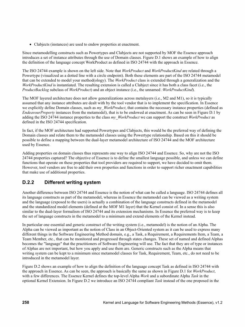
258 Kernel and Language for Software Engineering Methods (Essence), v1.2
• Clabjects (instances) are used to endow properties at enactment.
Since metamodelling constructs such as Powertypes and Clabjects are not supported by MOF the Essence approach introduces a set of instance attributes through the use of Domain classes. Figure D.1 shows an example of how to align the definition of the language concept WorkProduct as defined in ISO 24744 with the approach in Essence.
The ISO 24744 example is shown on the left side. Note that WorkProduct and WorkProductKind are related through a Powertype (visualized as a dotted line with a circle endpoint). Both these elements are part of the ISO 24744 metamodel that can be extended to model your method(ology). The WorkProduct class is extended through a generalization and the WorkProductKind is instantiated. The resulting extension is called a Clabject since it has both a class facet (i.e., the ProductBacklog subclass of WorkProduct) and an object instance (i.e., the unnamed :WorkProductKind).
The MOF layered architecture does not allow generalizations across metalayers (i.e., M2 and M1), so it is typically assumed that any instance attributes are dealt with by the tool vendor that is to implement the specification. In Essence we explicitly define Domain classes, such as my_WorkProduct, that contains the necessary instance properties (defined as EndeavourProperty instances from the metamodel), that is to be endowed at enactment. As can be seen in Figure D.1 by adding the ISO 24744 instance properties to the class my_WorkProduct we can support the construct WorkProduct as defined in the ISO 24744 specification.
In fact, if the MOF architecture had supported Powertypes and Clabjects, this would be the preferred way of defining the Domain classes and relate them to the metamodel classes using the Powertype relationship. Based on this it should be possible to define a mapping between the dual-layer metamodel architecture of ISO 24744 and the MOF architecture used by Essence.
Adding properties on domain classes thus represents one way to align ISO 24744 and Essence. So, why are not the ISO 24744 properties captured? The objective of Essence is to define the smallest language possible, and unless we can define functions that operate on these properties that tool providers are required to support, we have decided to omit them. However, tool vendors are free to add their own properties and functions in order to support richer enactment capabilities that make use of additional properties.
D.2.2 Different writing system
Another difference between ISO 24744 and Essence is the notion of what can be called a language. ISO 24744 defines all its language constructs as part of the metamodel, whereas in Essence the metamodel can be viewed as a writing system and the language (exposed to the users) is actually a combination of the language constructs defined in the metamodel and the standardized model elements (defined at the MOF M1 layer) that the Kernel consist of. In a sense this is also similar to the dual-layer formalism of ISO 24744 and its extension mechanisms. In Essence the preferred way is to keep the set of language constructs in the metamodel to a minimum and extend elements of the Kernel instead.
In particular one essential and generic construct of the writing system (i.e., metamodel) is the notion of an Alpha. The Alpha can be viewed as important as the notion of Class in an Object-Oriented system as it can be used to express many different things in the Software Engineering Method domain, e.g., a Task, a Requirement, a Requirements Item, a Team, a Team Member, etc., that can be monitored and progressed through states changes. These set of named and defined Alphas becomes the "language" that the practitioners of Software Engineering will use. The fact that they are of type or instances of Alphas are not important, but how you apply and use them are. Generic constructs such as the Alpha means that writing system can be kept to a minimum since metamodel classes for Task, Requirement, Team, etc., do not need to be introduced in the metamodel layer.
Figure D.2 shows an example of how to align the definition of the language concept Task as defined in ISO 24744 with the approach in Essence. As can be seen, the approach is basically the same as shown in Figure D.1 for WorkProduct, with a few differences. The Essence Kernel defines the top-level Alpha Work and a subordinate Alpha Task in the optional Kernel Extension. In Figure D.2 we introduce an ISO 24744 compliant Task instead of the one proposed in the

Kernel and Language for Software Engineering Methods (Essence), v1.2 259
optional Kernel extension. As can be seen this now contains the properties from the ISO 24744 definition of Task. If we want to use the instanceName property introduced by the Essence Alpha we would have to create a TaskExtension in the ISO 24744 approach containing this property.
Figure D.2 – Task example alignment between ISO 24744 and Essence
D.2.3 Definition of an ISO 24744 Kernel extension
Comparing the ISO 24744 and the Essence approach shows that both are built one a similar foundation separating the method and the endeavour: which in the ISO 24744 approach is supported by a dual-modeling approach with explicit Endeavour and Method(ology) domains, and in the Essence approach is separated into a metamodel (i.e., writing system or language as understood in the OMG context) and the Kernel providing the common starting ground.
• Some of the ISO 24744 concepts map to concepts in the Essence Language as explained in D.2.1.
o WorkProductKind maps to WorkProduct (language construct in Essence)
o WorkProduct maps to my_WorkProduct (abstract super class in Essence)
• Some of the ISO 24744 concepts map to elements in the Kernel (or optional Kernel extensions) as explained in D.2.2.
o Task can be mapped to Task (which is an Alpha in the optional Kernel extension)
Clabject
ISO 24744 Essence

260 Kernel and Language for Software Engineering Methods (Essence), v1.2
The naming differences related to WorkProduct, i.e., use of Kind and my_, between ISO 24744 and Essence are due to different use of naming conventions.
The ISO 24744 specification also defines a set of language concepts such as Milestone, Producer, Role, etc. that are not defined as part of the Essence Language. The reason that Essence does not define these as standardized language concepts are that there is no universal agreement of the definition of such terms and they are used differently in different practices. Instead The Essence language introduces the generic construct Pattern that can be used to define and express terms such as Milestone or Role according to specific practices or Kernel extensions that applies to a set of consistent practices. For those concepts in the ISO 24744 specification that cannot be mapped to a corresponding language element in the Essence language or defined as an Alpha the Pattern construct can be used to define a library of supplemental ISO 24744 language concepts.
Based on our analysis it should be possible to align the ISO 24744 and Essence approach using the techniques illustrated above. We advise that the SEMDM team can define an ISO 24744 Kernel extension similar to the KUALI-BEH Kernel extension.
D.3 Overview of ISO 24744 features This subclause provides an overview of ISO 24744 features.
Table D.1 – ISO 24744 features ISO 24744 language construct Description (single sentence)
Action An action is a usage event performed by a task upon a work product. ActionKind An action kind is a specific kind of action, characterized by a given cause (a
task kind), a given subject (a work product kind) and a particular type of usage.
Build A build is a stage with duration for which the major objective is the delivery of an incremented version of an already existing set of work products.
BuildKind A build kind is a specific kind of build, characterized by the type of result that it aims to produce.
CompositeWorkProduct A composite work product is a work product composed of other work products.
CompositeWorkProductKind A composite work product kind is a specific kind of composite work product, characterized by the kinds of work products that are part of it.
Conglomerate A conglomerate is a collection of related methodology elements that can be reused in different methodological contexts.
Constraint A constraint is a condition that holds or must hold at certain point in time. Document A document is a durable depiction of a fragment of reality. DocumentKind A document kind is a specific kind of document, characterized by its structure,
type of content and purpose. Element An element is an entity of interest to the metamodel. Element is an abstract
class, specialized into MethodologyElement and EndeavourElement. EndeavourElement An endeavour element is an element that belongs in the endeavour domain. Guideline A guideline is an indication of how a set of methodology elements can be used
during enactment.

Kernel and Language for Software Engineering Methods (Essence), v1.2 261
ISO 24744 language construct Description (single sentence)
HardwareItem A hardware item is a piece of hardware of interest to the endeavour. HardwareItemKind A hardware item kind is a specific kind of hardware item, characterized by its
mechanical and electronic characteristics, requirements and features. InstantaneousStage An instantaneous stage is a managed point in time within an endeavour. InstantaneousStageKind An instantaneous stage kind is a specific kind of instantaneous stage,
characterized by the kind of event that it represents. Language A language is a structure of model unit kinds that focus on a particular
modelling perspective. MethodologyElement A methodology element is an element that belongs in the methodology
domain. Milestone A milestone is an instantaneous stage that marks some significant event in the
endeavour. MilestoneKind A milestone kind is a specific kind of milestone, characterized by its specific
purpose and kind of event that it signifies. Model A model is an abstract representation of some subject that acts as the subject’s
surrogate for some well-defined purpose. ModelKind A model kind is a specific kind of model, characterized by its focus, purpose
and level of abstraction. ModelUnit A model unit is an atomic component of a model, which represents a cohesive
fragment of information in the subject being modelled. ModelUnitKind A model unit kind is a specific kind of model unit, characterized by the nature
of the information it represents and the intention of using such a representation.
ModelUnitUsage A model unit usage is a specific usage of a given model unit by a given model. ModelUnitUsageKind A model unit usage kind is a specific kind of model unit usage, characterized
by the nature of the use that a given model kind makes of a given model unit kind.
Notation A notation is a concrete syntax, usually graphical, that can be used to depict models created with certain languages.
Outcome An outcome is an observable result of the successful performance of any work unit of a given kind.
Person A person is an individual human being involved in a development effort. Phase A phase is a stage with duration for which the objective is the transition
between cognitive frameworks. PhaseKind A phase kind is a specific kind of phase, characterized by the abstraction level
and formality of the result that it aims to produce. PostCondition A postcondition is a constraint that is guaranteed to be satisfied after an action
of the associated kind is performed. PreCondition A precondition is a constraint that must be satisfied before an action of the
associated kind can be performed.
262 Kernel and Language for Software Engineering Methods (Essence), v1.2
ISO 24744 language construct Description (single sentence)
Process A process is a large-grained work unit that operates within a given area of expertise.
ProcessKind A process kind is a specific kind of process, characterized by the area of expertise in which it occurs.
Producer A producer is an agent that has the responsibility to execute work units. ProducerKind A producer kind is a specific kind of producer, characterized by its area of
expertise. Reference A reference is a specific linkage between a given methodology element and a
given source. Resource A resource is a methodology element that is directly used at the endeavour
level, without an instantiation process. Role A role is a collection of responsibilities that a producer can take. RoleKind A role kind is a specific kind of role, characterized by the involved
responsibilities. SoftwareItem A software item is a piece of software of interest to the endeavour. SoftwareItemKind A software item kind is a specific kind of software item, characterized by its
scope, requirements and features. Source A source is a source of information, experience or best practices. Stage A stage is a managed time frame within an endeavour. StageKind A stage kind is a specific kind of stage, characterized by the abstraction level
at which it works on the endeavour and the result that it aims to produce. StageWithDuration A stage with duration is a managed interval of time within an endeavour. StageWithDurationKind A stage with duration kind is a specific kind of stage with duration,
characterized by the abstraction level at which it works on the endeavour and the result that it aims to produce.
Task A task is a small-grained work unit that focuses on what must be done in order to achieve a given purpose.
TaskKind A task kind is a specific kind of task, characterized by its purpose within the endeavour.
TaskTechniqueMapping A task-technique mapping is a usage association between a given task and a given technique.
TaskTechniqueMappingKind A task-technique mapping kind is a specific kind of task-technique mapping, characterized by the mapped task kind and technique kind.
Team A team is an organized set of producers that collectively focus on common work units.
TeamKind A team kind is a specific kind of team, characterized by its responsibilities. Technique A technique is a small-grained work unit that focuses on how the given
purpose may be achieved. TechniqueKind A technique kind is a specific kind of technique, characterized by its purpose
within the endeavour.

Kernel and Language for Software Engineering Methods (Essence), v1.2 263
ISO 24744 language construct Description (single sentence)
Template A template is a methodology element that is used at the endeavour level through an instantiation process.
TimeCycle A time cycle is a stage with duration for which the objective is the delivery of a final product or service.
TimeCycleKind A time cycle kind is a specific kind of time cycle, characterized by the type of outcomes that it aims to produce.
Tool A tool is an instrument that helps another producer to execute its responsibilities in an automated way.
ToolKind A tool kind is a specific kind of tool, characterized by its features. WorkPerformance A work performance is an assignment and responsibility association between
a particular producer and a particular work unit. WorkPerformanceKind A work performance kind is a specific kind of work performance,
characterized by the purpose of the inherent assignment and responsibility association.
WorkProduct A work product is an artefact of interest for the endeavour. WorkProductKind A work product kind is a specific kind of work product, characterized by the
nature of its contents and the intention behind its usage. WorkUnit A work unit is a job performed, or intended to be performed, within an
endeavour. WorkUnitKind A work unit kind is a specific kind of work unit, characterized by its purpose
within the endeavour.

264 Kernel and Language for Software Engineering Methods (Essence), v1.2
This page intentionally left blank.

Kernel and Language for Software Engineering Methods (Essence), v1.2 265
Annex E: Practice Examples
(Informative)
E.1 Introduction This annex provides working examples to demonstrate the use of the Kernel and Language to describe practices.
E.2 Practices
E.2.1 Overview
This subclause contains illustrative examples of the following:
• Scrum
• User Story
• Multi-phase Waterfall
• Lifecycle examples
E.2.2 Scrum
E.2.2.1 Overview This subclause illustrates the Essence approach by modeling the Scrum4 project management practice. The Scrum practice as documented here is for illustrative purposes only and explores how the Scrum practice may be mapped to the Essence Kernel and Language. It should not be interpreted as a definitive example of how Scrum should be represented.
E.2.2.2 Practice The following Scrum concepts were identified from the Scrum guide [Schwaber and Sutherland 2011]:
• Scrum team (roles)
o Product Owner
o Development Team (of developers)
o Scrum Master
• Scrum events
o The Sprint
o Sprint Planning Meeting
4 K. Schwaber and J. Sutherland, "The Scrum Guide", Scrum.org, October 2011. http://www.scrum.org/storage/scrumguides/Scrum_Guide.pdf

266 Kernel and Language for Software Engineering Methods (Essence), v1.2
o Daily Scrum
o Sprint Review
o Sprint Retrospective
• Scrum artifacts
o Product Backlog
o Sprint Backlog
o Increment
Graphical syntax
Figure E.1 – Scrum practice
Textual syntax kernel ESSENCE_kernel:
"..." owns { alpha Work: "...." with states { state someState { "..." }
Scrum Requirements
Work
Team
SoftwareSystem
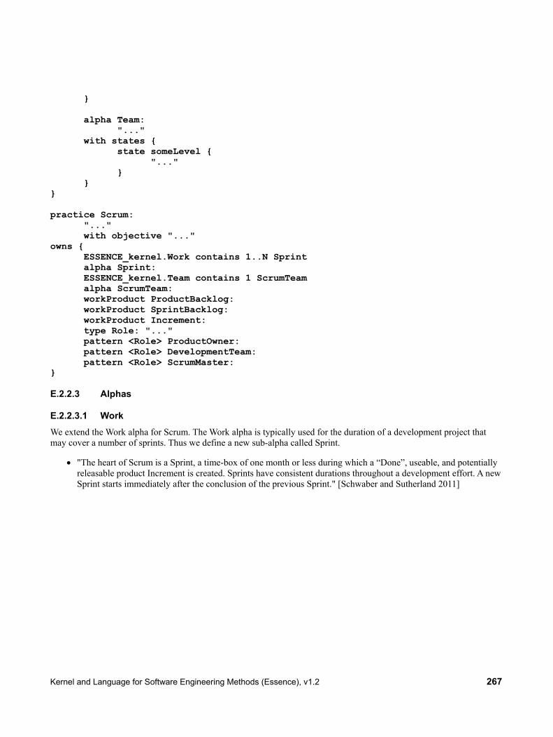
Kernel and Language for Software Engineering Methods (Essence), v1.2 267
}
alpha Team: "..." with states { state someLevel { "..." } } } practice Scrum:
"..." with objective "..."
owns { ESSENCE_kernel.Work contains 1..N Sprint
alpha Sprint: ESSENCE_kernel.Team contains 1 ScrumTeam alpha ScrumTeam: workProduct ProductBacklog: workProduct SprintBacklog: workProduct Increment: type Role: "..." pattern <Role> ProductOwner: pattern <Role> DevelopmentTeam: pattern <Role> ScrumMaster: }
E.2.2.3 Alphas
E.2.2.3.1 Work We extend the Work alpha for Scrum. The Work alpha is typically used for the duration of a development project that may cover a number of sprints. Thus we define a new sub-alpha called Sprint.
• "The heart of Scrum is a Sprint, a time-box of one month or less during which a “Done”, useable, and potentially releasable product Increment is created. Sprints have consistent durations throughout a development effort. A new Sprint starts immediately after the conclusion of the previous Sprint." [Schwaber and Sutherland 2011]

268 Kernel and Language for Software Engineering Methods (Essence), v1.2
Graphical syntax
Figure E.2 – Sprint sub-alpha of Work
The Sprint has its own state graph. Scrum comes with its own specific set of rules that should be defined as part of the practice, whereas the Work state machine and its associated checkpoints are more general.
Graphical syntax
Figure E.3 – The states of the Sprint sub-alpha

Kernel and Language for Software Engineering Methods (Essence), v1.2 269
Textual syntax alpha Sprint:
"The heart of Scrum is a Sprint, a time-box of one month or less during which a “Done”, useable, and potentially releasable product Increment is created. Sprints have consistent durations throughout a development effort. A new Sprint starts immediately after the conclusion of the previous Sprint. (...continues...)"
with states {
state Planned { "The work has been requested and planned." checks { item c1 {"Sprint Planning Meeting is held."} item c2 {"Product Owner presents ordered Product Backlog items to the Development Team."}
item c3 {"Development Team decides how it will build this functionality into a “Done” product Increment during the Sprint"}
item c4 {"Scrum Team crafts a Sprint Goal."} item c5 {"Development Team defines a Sprint Backlog."} } } state Started { "The work is proceeding." checks {
item c1 {"Team is taking their work items from the Sprint Backlog"}
} } state UnderControl {
"The work is going well, risks are under control, and productivity levels are sufficient to achieve a satisfactory result."
checks { item c1 {"Daily Scrum optimizes the probability that the Development Team will meet the Sprint Goal."} item c2 {"Every day, the Development Team should be able to explain to the Product Owner and Scrum Master how it intends to work together as a self-organizing team to accomplish the goal and create the anticipated increment in the remainder of the Sprint."}
} } state Concluded { "The work to produce the results has been concluded." checks {
item c1 {"During the Sprint Review, the Scrum Team and stakeholders collaborate about what was done in the Sprint."}
} }

270 Kernel and Language for Software Engineering Methods (Essence), v1.2
state Closed { "All remaining housekeeping tasks have been completed and the work has been officially closed."
checks { item c1 {"A Sprint Review Meeting is held at the end of the Sprint."} item c2 {"The Sprint Retrospective occurs after the Sprint Review and prior to the next Sprint Planning Meeting."}
} } }
E.2.2.3.2 Team The Scrum practice relates to the Team alpha. The Team alpha refers to the individuals working in the team, i.e., members that may be represented by a sub-alpha. Scrum defines a specific Scrum Team which consists of a Product Owner, the Development Team, and a Scrum Master.
• "The Scrum Team consists of a Product Owner, the Development Team, and a Scrum Master. Scrum Teams are self-organizing and cross-functional. Self-organizing teams choose how best to accomplish their work, rather than being directed by others outside the team. Cross-functional teams have all competencies needed to accomplish the work without depending on others not part of the team. The team model in Scrum is designed to optimize flexibility, creativity, and productivity." [Schwaber and Sutherland 2011]
Graphical syntax
Figure E.4 – Scrum Team
Scrum mandates that one sole person should take on the role of a Product Owner and another sole person should take on the role of the Scrum Master. These types of constraints could be added as checkpoints on the Team alpha itself, but another alternative would be to define a specific Scrum Team as a sub-alpha. The introduction of a specific sub-alpha would allow us to easier extend and scale the practice to Scrum of Scrums, including managing different types of teams not all following Scrum.

Kernel and Language for Software Engineering Methods (Essence), v1.2 271
Graphical syntax
Figure E.5 – The states of the Scrum Team sub-alpha
Textual syntax alpha ScrumTeam:
"The Scrum Team consists of a Product Owner, the Development Team, and a Scrum Master. Scrum Teams are self-organizing and cross-functional. Self-organizing teams choose how best to accomplish their work, rather than being directed by others outside the team. Cross-functional teams have all competencies needed to accomplish the work without depending on others not part of the team. The team model in Scrum is designed to optimize flexibility, creativity, and productivity. (...continues...)" with states {
state Established { "Scrum Team is established." checks { item c1 {"The Product Owner is assigned."}
item c2 {"Developers are assigned to the Development Team."}
item c3 {"The Scrum Master is assigned."} }
} }
E.2.2.4 Work Products
E.2.2.4.1 Product Backlog The Product Backlog and Sprint Backlog are associated with the Requirements alpha.
• "The Product Backlog is an ordered list of everything that might be needed in the product and is the single source of requirements for any changes to be made to the product. The Product Owner is responsible for the Product Backlog, including its content, availability, and ordering." [Schwaber and Sutherland 2011]

272 Kernel and Language for Software Engineering Methods (Essence), v1.2
Graphical syntax
Figure E.6 – Product Backlog
Textual syntax workProduct ProductBacklog:
"The Product Backlog is an ordered list of everything that might be needed in the product and is the single source of requirements for any changes to be made to the product. The Product Owner is responsible for the Product Backlog, including its content, availability, and ordering. (...continues...)"
with levels { level someLevel { "..." } }
E.2.2.4.2 Sprint Backlog The Sprint Backlog is associated with the Sprint sub-alpha.
• "The Sprint Backlog is the set of Product Backlog items selected for the Sprint plus a plan for delivering the product Increment and realizing the Sprint Goal. The Sprint Backlog is a forecast by the Development Team about what functionality will be in the next Increment and the work needed to deliver that functionality." [Schwaber and Sutherland 2011]

Kernel and Language for Software Engineering Methods (Essence), v1.2 273
Graphical syntax
Figure E.7 – Sprint Backlog
Textual syntax workProduct SprintBacklog:
"The Sprint Backlog is the set of Product Backlog items selected for the Sprint plus a plan for delivering the product Increment and realizing the Sprint Goal. The Sprint Backlog is a forecast by the Development Team about what functionality will be in the next Increment and the work needed to deliver that functionality. (...continues...)"
with levels {
level someLevel { "..." } }
E.2.2.4.3 Increment The Increment is associated with the Software System alpha.
• "The Increment is the sum of all the Product Backlog items completed during a Sprint and all previous Sprints. At the end of a Sprint, the new Increment must be “Done,” which means it must be in useable condition and meet the Scrum Team’s Definition of “Done.” It must be in useable condition regardless of whether the Product Owner decides to actually release it." [Schwaber and Sutherland 2011]

274 Kernel and Language for Software Engineering Methods (Essence), v1.2
Graphical syntax
Figure E.8 – Increment
Textual syntax workProduct Increment:
"The Increment is the sum of all the Product Backlog items completed during a Sprint and all previous Sprints. At the end of a Sprint, the new Increment must be “Done,” which means it must be in useable condition and meet the Scrum Team’s Definition of “Done.” It must be in useable condition regardless of whether the Product Owner decides to actually release it. (...continues...)"
with levels {
level someLevel { "..." } }
E.2.2.5 Activities The identified Scrum events may be mapped to corresponding activities. The concept of sprint however describes an iteration that we will map to a sub-alpha of Work. This gives us the following activities:
• Sprint Planning Meeting
• Daily Scrum
• Sprint Review
• Sprint Retrospective

Kernel and Language for Software Engineering Methods (Essence), v1.2 275
Graphical Syntax
Figure E.9 – Scrum activities
E.2.2.5.1 Sprint Planning Meeting The Sprint Planning Meeting is associated with the Prepare to do the Work activity space.
• "The work to be performed in the Sprint is planned at the Sprint Planning Meeting. This plan is created by the collaborative work of the entire Scrum Team. The Sprint Planning Meeting is time-boxed to eight hours for a one-month Sprint. For shorter Sprints, the event is proportionately shorter. For example, two-week Sprints have four-hour Sprint Planning Meetings." [Schwaber and Sutherland 2011]
Graphical syntax
Figure E.10 – Sprint Planning Meeting
E.2.2.5.2 Daily Scrum The Daily Scrum is associated with the Track Progress activity space.
• "The Daily Scrum is a 15-minute time-boxed event for the Development Team to synchronize activities and create a plan for the next 24 hours. This is done by inspecting the work since the last Daily Scrum and forecasting the work that could be done before the next one." [Schwaber and Sutherland 2011]
Graphical syntax

276 Kernel and Language for Software Engineering Methods (Essence), v1.2
Figure E.11 – Daily Scrum
Textual syntax activity DailyScrum:
"The Daily Scrum is a 15-minute time-boxed event for the Development Team to synchronize activities and create a plan for the next 24 hours. This is done by inspecting the work since the last Daily Scrum and forecasting the work that could be done before the next one."
targets Sprint.Concluded DailyScrum -- "part-of" --> ESSENCE_kernel.TrackProgress
E.2.2.5.3 Sprint Review The Sprint Review is associated with the Track Progress activity space.
• "A Sprint Review is held at the end of the Sprint to inspect the Increment and adapt the Product Backlog if needed. During the Sprint Review, the Scrum Team and stakeholders collaborate about what was done in the Sprint. Based on that and any changes to the Product Backlog during the Sprint, attendees collaborate on the next things that could be done. This is an informal meeting, and the presentation of the Increment is intended to elicit feedback and foster collaboration." [Schwaber and Sutherland 2011]
Graphical syntax
Figure E.12 – Sprint Review
Textual syntax activity SprintReview:
"A Sprint Review is held at the end of the Sprint to inspect the Increment and adapt the Product Backlog if needed. During the Sprint Review, the Scrum Team and stakeholders collaborate about what was done in the Sprint. Based on that and any changes to the Product Backlog during the Sprint, attendees collaborate on the next things that could be done. This is an informal meeting, and the presentation of the Increment is intended to elicit feedback and foster collaboration."
targets Sprint.Concluded, Sprint.Closed SprintReview -- "part-of" --> ESSENCE_kernel.TrackProgress
E.2.2.5.4 Sprint Retrospective The Sprint Retrospective is associated with the Support the Team activity space.
• "The Sprint Retrospective is an opportunity for the Scrum Team to inspect itself and create a plan for improvements to be enacted during the next Sprint. The Sprint Retrospective occurs after the Sprint Review and

Kernel and Language for Software Engineering Methods (Essence), v1.2 277
prior to the next Sprint Planning Meeting. This is a three-hour time-boxed meeting for one-month Sprints. Proportionately less time is allocated for shorter Sprints." [Schwaber and Sutherland 2011]
Graphical syntax
Figure E.13 – Sprint Retrospective
E.2.2.6 Roles Roles can be described as patterns:
• Product Owner
• Development Team (of developers)
• Scrum Master
E.2.2.6.1 Product Owner
Textual syntax type Role: "..." pattern <Role> ProductOwner:
"The Product Owner is responsible for maximizing the value of the product and the work of the Development Team. How this is done may vary widely across organizations, Scrum Teams, and individuals. (...continues...)"
E.2.2.6.2 Development Team
Textual syntax type Role: "..." pattern <Role> DevelopmentTeam:
"The Development Team consists of professionals who do the work of delivering a potentially releasable Increment of “Done” product at the end of each Sprint. Only members of the Development Team create the Increment. (...continues...)"
E.2.2.6.3 Scrum Master
Textual syntax type Role: "..." pattern <Role> ScrumMaster:

278 Kernel and Language for Software Engineering Methods (Essence), v1.2
"The Scrum Master is responsible for ensuring Scrum is understood and enacted. Scrum Masters do this by ensuring that the Scrum Team adheres to Scrum theory, practices, and rules. The Scrum Master is a servant-leader for the Scrum Team. The Scrum Master helps those outside the Scrum Team understand which of their interactions with the Scrum Team are helpful and which aren’t. The Scrum Master helps everyone change these interactions to maximize the value created by the Scrum Team. (...continues...)"
E.2.3 User Story
E.2.3.1 Practice
Graphical syntax
Figure E.14 – User Story practice
Textual syntax kernel ESSENCE_kernel:
"..." owns { alpha Requirements: "...." with states { state someState { "..." } } } practice UserStory:
"..." with objective "..."
owns { ESSENCE_kernel.Requirements contains 1..N UserStory workProduct UserStoryCard: }
E.2.3.2 Work Products
E.2.3.2.1 User Story A User Story can be seen as a requirement item sub-alpha of Requirements that you want to monitor the state of. This requirement item is described by a User Story Card.

Kernel and Language for Software Engineering Methods (Essence), v1.2 279
Graphical syntax
Figure E.15 – User Story
Textual syntax alpha UserStory:
"A User Story is an Independent, Negotiable, Valuable, Estimatable, Small, Testable requirement (INVEST)"
with states { state Described { "The User Story is described." checks { item c1 {"User Story is described by the customer."} item c2 {"User Story is prioritized by the customer."} } } state Understood {"The User Story has been analyzed by the Team" checks {
item c1 {"The User Story has been broken down into tasks by the developers."} item c2 {"The User Story has been estimated by the developers."}
} } state Implemented {"The User Story has been implemented." checks { item c1 {"The User Story has been implemented."} item c2 {"The implementation has been tested."} }

280 Kernel and Language for Software Engineering Methods (Essence), v1.2
} state Fulfilled {"The User Story has been fulfilled." checks { item c1 {"The Customer has approved the implementation."} } } } workProduct UserStoryCard:
"The User Story Card contains the description of the User Story. User stories generally follow the following template: “As a <role>, I want <goal/desire> so that <benefit>” “As a <role>, I want <goal/desire>”"
with levels {
level someLevel { "..."
} }
E.2.3.3 Activities
E.2.3.3.1 Write User Story
Graphical syntax
Figure E.16 – Write User Story
Textual syntax activity WriteUserStory: "..." targets UserStory.Described WriteUserStory -- "part-of" --> SEMAT_kernel.UnderstandTheRequirements
E.2.3.3.2 Prioritize User Story
Graphical syntax
Figure E.17 – Prioritize User Story

Kernel and Language for Software Engineering Methods (Essence), v1.2 281
Textual syntax activity PrioritizeUserStory: "..." targets UserStory.Described PrioritizeUserStory -- "part-of" --> SEMAT_kernel.UnderstandTheRequirements
E.2.3.3.3 Estimate User Story
Graphical syntax
Figure E.18 – Estimate User Story
Textual syntax activity EstimateUserStory: "..." targets UserStory.Understood EstimateUserStory -- "part-of" --> SEMAT_kernel.UnderstandTheRequirements
E.2.4 Multi-phase Waterfall
In some practices in common use, there are multiple phases of Requirements Definition, each adding more detail.
• Multiple Requirements and Design Activities normally flow top down.
• Multi-phase Testing Activities normally flow bottom up.
This practice example is closely related to the so-called V-Model for software process engineering http://www.the-software-experts.de/e_dta-sw-process.htm .
• Actual Flow of Activities associated with each phase can be quiet complex in a real project.
• Requirements alpha specializations are needed to model requirement documents from each phase.
E.2.4.1 Activities The general form of the V-model of Activities for the Multi-phase Waterfall practice is shown in Figure E.19.

282 Kernel and Language for Software Engineering Methods (Essence), v1.2
Figure E.19 – Multi-phase Waterfall Practice Activities Flow
Figure E.19 shows an example of “V-Model” for Multi-phase Waterfall Practice. Each Test Activity verifies/validates work products of one Requirements/Design Activity. Normal progression flows from left to right. If defects are detected or rewind is required, process flows back to appropriate point thru the depicted virtual node
E.2.4.1.1 Requirements Definition Phase
Description Major work products
• Confirm the systematization requirements to define functional (system functions, data, interface) and non-functional requirements
• Define and outline design of the system and examine the feasibility of the system.
• Develop a project plan and establish management measurers to carry out the project.
• Use cases & Scenario
• Business flows
• Business rules
• Data model (High-level)
• Execution environment prescription (as Non-functional requirement)
• Business operational test spec.
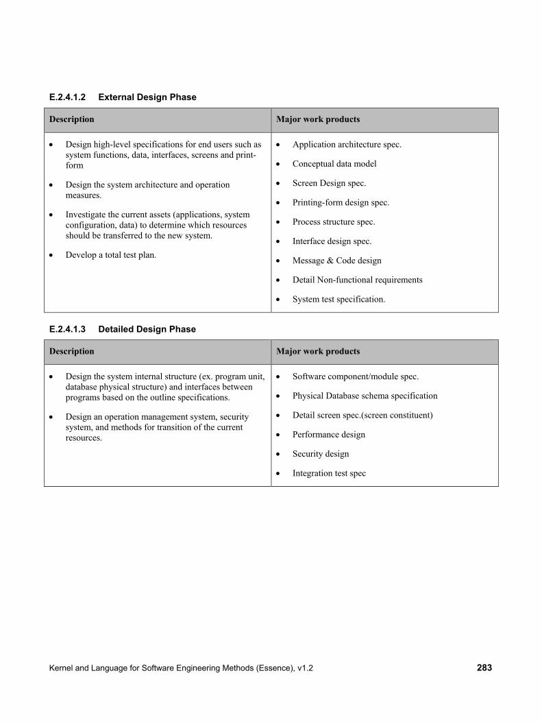
Kernel and Language for Software Engineering Methods (Essence), v1.2 283
E.2.4.1.2 External Design Phase
Description Major work products
• Design high-level specifications for end users such as system functions, data, interfaces, screens and print-form
• Design the system architecture and operation measures.
• Investigate the current assets (applications, system configuration, data) to determine which resources should be transferred to the new system.
• Develop a total test plan.
• Application architecture spec.
• Conceptual data model
• Screen Design spec.
• Printing-form design spec.
• Process structure spec.
• Interface design spec.
• Message & Code design
• Detail Non-functional requirements
• System test specification.
E.2.4.1.3 Detailed Design Phase
Description Major work products
• Design the system internal structure (ex. program unit, database physical structure) and interfaces between programs based on the outline specifications.
• Design an operation management system, security system, and methods for transition of the current resources.
• Software component/module spec.
• Physical Database schema specification
• Detail screen spec.(screen constituent)
• Performance design
• Security design
• Integration test spec

284 Kernel and Language for Software Engineering Methods (Essence), v1.2
E.2.4.1.4 Implementation/Programming Phase
Description Major work products
• Define program structure and design program logic
• Develop and complete programs based on the program design
• Implement the database based on the data model.
• Test each program module individually to verify correctness and quality.
• Source code
• Middleware/Hardware configuration specification.
• Database definition Language
E.2.4.1.5 Integration Test Phase
Description Major work products
• Test each process by integrating programs to verify the application.
• Test interfaces between all processes
• Confirm interfaces between external systems
• Result reports for Integration test spec.
E.2.4.1.6 System Test Phase
Description Major work products
• Test the business system functions on the actual machines.
• Test the entire system by evaluating system performance, reliability, operability, security, etc.
• Result reports for System test spec.

Kernel and Language for Software Engineering Methods (Essence), v1.2 285
E.2.4.1.7 Operational Test Phase
Description Major work products
• Test business operations in the real environment with actual machines and real data. This test is performed by end users.
• Validate the business functions, performance, reliability, operability, and security.
• Make decision to transit from test operation to real operation, and perform a transition.
• Result reports for business operational test.
E.2.4.2 Alpha Extensions for Multi-Phase Waterfall Requirements
Figure E.20 – Multi-phase Waterfall Requirements Alpha Extensions and Requirements Spec Work Products
High Level Requirements Specs (Functional and Non-Functional) are produced by Requirements Definition Activity.
External Requirements Specs (Functional and Non-Functional) are produced by External Design Activity.
Detailed Requirements Specs (Functional and Non-Functional) are produced by Detailed Design Activity.
Each Requirements extension Alpha has:
• Its own state values, the same as specified for the Requirements Alpha;
o Conceived; Bounded; Coherent; Described; Addressed; Fulfilled
• Functional and Non-Functional Requirements Spec Work Products
o each having Sub-Alphas for every Requirement Item, with their own state values (the same as specified for the Requirement Item Sub-Alpha Kernel Extension

286 Kernel and Language for Software Engineering Methods (Essence), v1.2
o Requirements Alpha Extension state transitions conditional on Requirements Item Sub-alpha state transitions
E.2.4.3 Lifecycle Diagram for Multi-Phase Waterfall Requirements Alpha Extensions
Figure E.21 – Lifecycle Diagram for Multi-Phase Waterfall Requirements Alpha Extensions
E.2.4.4 Extensions of Requirement Item Alpha for Tracking Individual Multi-Phase Waterfall Requirement Items
If a project needs to track to state of each individual requirement item, the following Sub-Alpha extensions of the Requirement Item kernel Extension Sub-alpha can be employed.
The individual Requirement Work products are part of their respective Requirements Spec (Functional or Non-Functional) associated with their parent Requirements Alpha Extension.

Kernel and Language for Software Engineering Methods (Essence), v1.2 287
Figure E.22 – High-Level Requirements Sub-Alphas and Requirement Work Products
Figure E.23 – External Requirements Sub-Alphas and Requirement Work Products

288 Kernel and Language for Software Engineering Methods (Essence), v1.2
Figure E.24 – Detailed Requirements Sub-Alphas and Requirement Work Products
E.2.5 Lifecycle Examples
The Essence Kernel enables practices to define lifecycles by sequencing a number of patterns, one for each phase and/or milestone in the lifecycle.
This subclause provides illustrations of a number of typical software engineering lifecycles:
• A Unified Process lifecycle
• A waterfall lifecycle
• A set of complementary application development lifecycles
• A funding and decision making lifecycle
When reading these subclauses one should bear in mind that a lifecycle practice can do more than just arrange the alpha states, it can also add items to the checklists, activities to formally review the milestones and any other planning or review guidance it sees fit.
All the lifecycles are illustrated using the template shown in Figure E.25.

Kernel and Language for Software Engineering Methods (Essence), v1.2 289
Figure E.25 – Lifecycle template
Each Kernel Alpha and its states are shown in a vertical column with their creation at the top and their destruction at the bottom. Milestones are shown as a vertical bar across the grid starting with an inverted triangle to represent the milestone and continuing with a white line over which are shown the states to be achieved to successfully pass the milestone. Where achieving a state is either recommended or optional the state is shown with a dashed outline and italicized text.
E.2.5.1 The Unified Process Lifecycle An illustration of the Unified Process Lifecycle is shown in Figure E.26. In the Unified Process Lifecycle there are four phases: Inception, Elaboration, Construction and Transition. Each of these ends in a distinct milestone: Lifecycle Objectives Milestone, Lifecycle Architecture Milestone, Initial Operational Capability, Project End. In Figure E.26, the milestones are represented by the blue inverted triangles but the names are suppressed to keep things simple.

290 Kernel and Language for Software Engineering Methods (Essence), v1.2
Figure E.26 – The Unified Process lifecycle
E.2.5.2 The Waterfall Lifecycle An illustration of a Waterfall Lifecycle is shown in Figure E.27. In this case there are six phases: Initiation, Requirements, Analysis and Design, Implementation, Testing, and Deployment. Each of these ends in a distinct milestone, which in this case are not named.
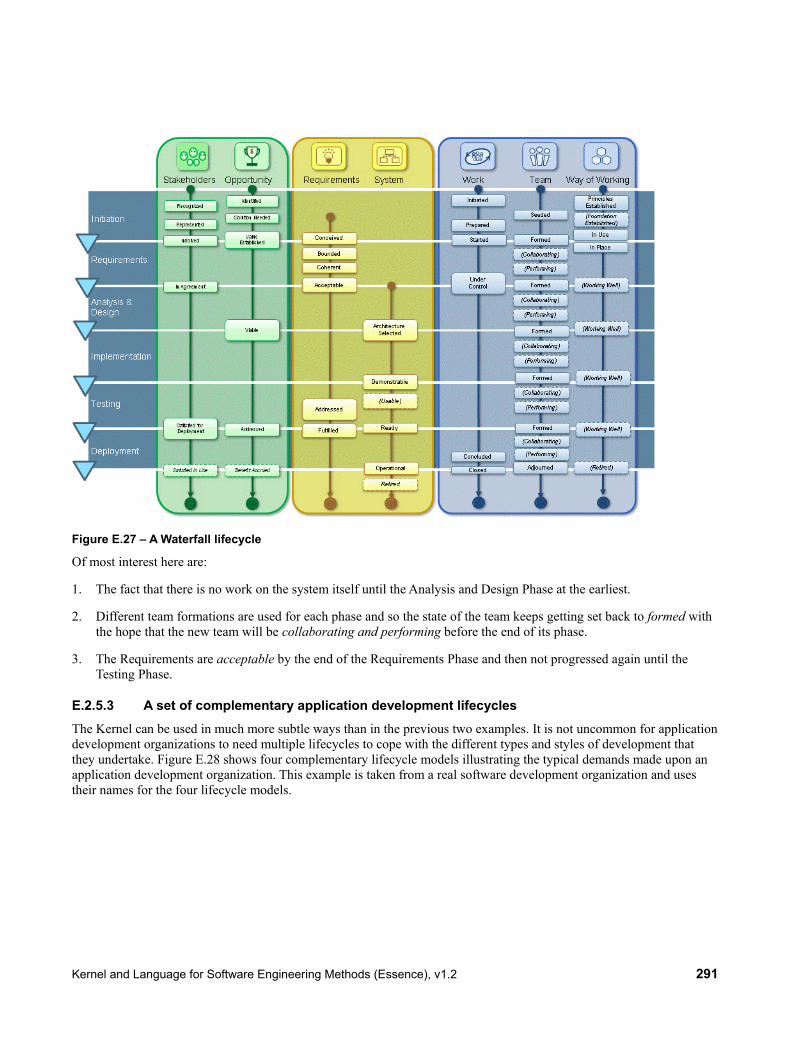
Kernel and Language for Software Engineering Methods (Essence), v1.2 291
Figure E.27 – A Waterfall lifecycle
Of most interest here are:
1. The fact that there is no work on the system itself until the Analysis and Design Phase at the earliest.
2. Different team formations are used for each phase and so the state of the team keeps getting set back to formed with the hope that the new team will be collaborating and performing before the end of its phase.
3. The Requirements are acceptable by the end of the Requirements Phase and then not progressed again until the Testing Phase.
E.2.5.3 A set of complementary application development lifecycles The Kernel can be used in much more subtle ways than in the previous two examples. It is not uncommon for application development organizations to need multiple lifecycles to cope with the different types and styles of development that they undertake. Figure E.28 shows four complementary lifecycle models illustrating the typical demands made upon an application development organization. This example is taken from a real software development organization and uses their names for the four lifecycle models.

292 Kernel and Language for Software Engineering Methods (Essence), v1.2
Figure E.28 – Different types of development need different methods and lifecycles
Each lifecycle model is supported by a method, each of which is built on the same kernel, many of which share the same practices, and each of which has its own lifecycle. The four lifecycles are shown in Figure E.29. Here the four lifecycles are deliberately shown in a single diagram to make the differences in the arrangements of the states easily visible. Unfortunately this makes the wording very hard to read. If you are interested in the details of the figures they are repeated at a larger size in Figure E.30, Figure E.31, Figure E.32, and Figure E.33.
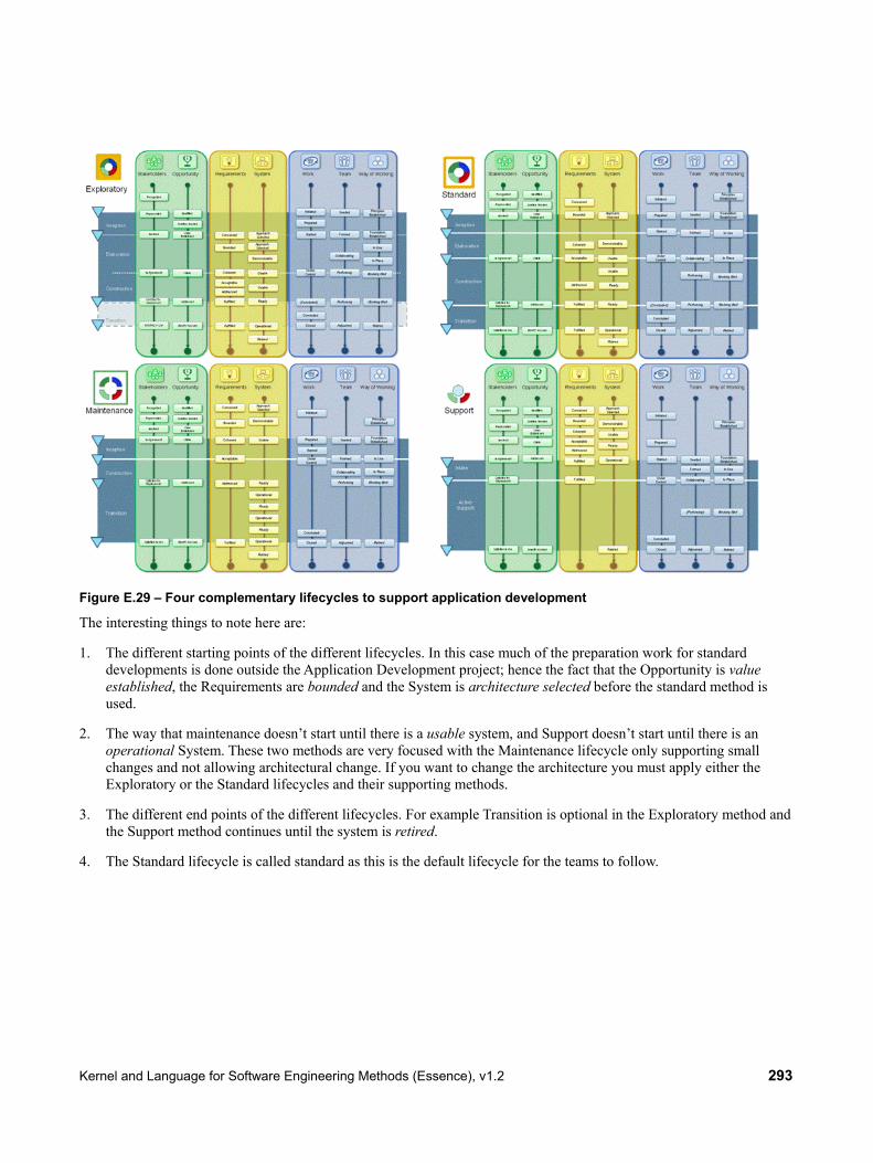
Kernel and Language for Software Engineering Methods (Essence), v1.2 293
Figure E.29 – Four complementary lifecycles to support application development
The interesting things to note here are:
1. The different starting points of the different lifecycles. In this case much of the preparation work for standard developments is done outside the Application Development project; hence the fact that the Opportunity is value established, the Requirements are bounded and the System is architecture selected before the standard method is used.
2. The way that maintenance doesn’t start until there is a usable system, and Support doesn’t start until there is an operational System. These two methods are very focused with the Maintenance lifecycle only supporting small changes and not allowing architectural change. If you want to change the architecture you must apply either the Exploratory or the Standard lifecycles and their supporting methods.
3. The different end points of the different lifecycles. For example Transition is optional in the Exploratory method and the Support method continues until the system is retired.
4. The Standard lifecycle is called standard as this is the default lifecycle for the teams to follow.

294 Kernel and Language for Software Engineering Methods (Essence), v1.2
Figure E.30 – The Exploratory lifecycle
Figure E.31 – The Standard lifecycle

Kernel and Language for Software Engineering Methods (Essence), v1.2 295
Figure E.32 – The Maintenance lifecycle
Figure E.33 – The Support lifecycle

296 Kernel and Language for Software Engineering Methods (Essence), v1.2
E.3 Composing Practices into Methods
E.3.1 Composing Scrum and User Story
In Scrum requirement items are expressed as Product Backlog items. Scrum does not provide any guidance on how to express these requirement items. Many Scrum teams adopt user stories to express their requirements. A simple composition of the Scrum and User Story work products with respect to the Requirements alpha is shown below.
Figure E.34 – Merging User Story with Scrum
This simple composition adds work products from different practices to the same alpha, and also relates the sub-alphas of Requirements. The result of the merger is shown below.
Figure E.35 – Scrum with User Story

Kernel and Language for Software Engineering Methods (Essence), v1.2 297
E.4 Enactment of Methods The purpose of this subclause is to illustrate the enactment of methods using a simple example. This example is based on the examples discussed so far in E.2.2, E.2.3, and E.3 above. The example uses the notion of cards and does not make any implication on whether these cards are handled physically or as digital artifacts in a tool.
E.4.1 The Initial Set of Cards
How to find the initial set of cards is described in 9.5.3.2 of the specification. The initial situation for this example is to use a method that is a composition of Scrum and User Story on an endeavor. Thus the initial set of cards contains the following elements independent of the current situation in the actual endeavor:
• One Alpha card for each of the Kernel Alphas;
• One Activity Space card for each of the Kernel Activity Spaces;
• One Competency card for each of the Kernel Competencies;
• One Work Product card for work product “Product Backlog”, attached to the Alpha card for Alpha “Requirements”;
• Seven Activity cards, one for each of the four Activities defined in the Scrum practice and the three Activities defined in the User Story practice, each attached to an Activity Space card as described by the practice.
In addition, the current situation in the actual endeavor is considered, adding the following cards to the set:
• Assuming there is just one Scrum Team, one Alpha card for that team is added (attached to the Alpha card for Alpha “Team”);
• Assuming three Sprints have been planned, three Alpha cards for Alpha “Sprint” are added (attached to the Alpha card for Alpha “Work”) as well as three Work Product cards for Work Product “Sprint Backlog” (attached to the Alpha card for the respective Sprint);
• Assuming the team is currently working on the first Increment, one Work Product card for Work Product “Increment” is added (attached to the Alpha card for Alpha “Software System”);
• Assuming three User Stories have been described so far, three Alpha cards for Alpha “User Story” are added (attached to the Alpha card for Alpha “Requirements”) as well as three Work Product cards for Work Product “User Story Card” (attached to the Alpha card for the respective User Story.
For each individual Alpha card named above, a set of Alpha State cards for this particular Alpha is added to the set as well, attached to the respective Alpha card.
See Figure E.36 for an illustration of the complete initial set of cards.

298 Kernel and Language for Software Engineering Methods (Essence), v1.2
Figure E.36 – Illustration of the complete initial set of cards for the example. Top section shows Alpha cards, attached Work Product cards (rotated) and attached Alpha State cards (small). Middle section shows Competency cards. Bottom section shows Activity Space cards with attached Activity cards (rotated).
E.4.2 Determining the Overall State for the First Time
How to determine the overall state of the endeavor is described in 9.5.3.3 of the specification. For each of the Alpha cards, the attached set of Alpha State cards is used. In the example, the set of Alpha State cards for Alpha “Scrum Team” contains only one card for State “Established.” Assuming the Scrum Team has a Product Owner assigned, a Scrum Master assigned and the Developers assigned, all checkpoints on this card are fulfilled, this state is considered the current state for Alpha “Scrum Team.”
All other sets of Alpha State cards are handled the same way. Assuming that on one of the Sprint Alphas all checkpoints on the first three Alpha State cards are fulfilled, but the checkpoint on the fourth card is not, this Sprint is considered to be in state “Under Control.” Assuming for the other two Sprints, no Sprint planning meeting has been held yet, not even the checkpoints of the first Alpha State card are fulfilled. Consequently, these Alphas are considered to be in some anonymous initial state.
See Figure E.37 for an illustration of the cards marking the overall state.

Kernel and Language for Software Engineering Methods (Essence), v1.2 299
Figure E.37 – Illustration of the individual Alpha State cards marking the overall state. States with all checkpoints fulfilled in the example are ticked off with a green check mark at the related Alpha State cards.
E.4.3 Generating Guidance for the First Time
How to generate guidance based on the current state of the endeavor is described in 9.5.3.4 of the specification. It is based on the decision on what should be the next Alpha State to be reached. According to the Scrum practice, a good next target state is “Concluded” in Alpha Sprint. Assuming this is selected as a target state, the guidance returned includes two Activities: “Daily Scrum” and “Sprint Review”, because these two have the target state in their completion criteria. Assuming state “Understood” on some User Story Alpha as a target state, the guidance is to perform Activity “Estimate User Story”.
Since generating guidance does not mean to instatiate Activities automatically, many requests for guidance for different target states (even on the same Alpha) can be issued without affecting the current state of the endeavor and the set of cards directly.
E.4.4 Updating the Overall State
At some point in time after the generation of guidance the overall state is updated again. Assuming the team has held a Sprint Review, a Sprint Retrospective, and a Sprint Planning Meeting (thus starting the next Sprint), several updates can be made to the overall state and to the set of cards:
• The Sprint that was in Alpha State “Under Control” so far is now in Alpha State “Closed,” which is its final state.
• One of the Sprints that were in the anonymous initial state so far is now in Alpha State “Planned.”
• A new Work Product card for Work Product “Increment” is added to the Alpha “Software System,” representing the next increment being created in the Sprint.
Assuming the team has also spent some time on the User Stories, bringing all of them to Alpha State “Understood,” this may cause the Alpha “Requirements” to move to Alpha State “Acceptable.”
Assuming the person who was assigned to the role of the Product owner so far leaves the endeavor, one checkpoint for Alpha State “Established” on Alpha “Scrum Team” is no longer fulfilled, thus this Alpha is not in Alpha State

300 Kernel and Language for Software Engineering Methods (Essence), v1.2
“Established” any more, but goes back to its anonymous initial state. This will also have an effect on Alphas “Work” and “Team,” forcing them to go back some Alpha States as well.
See Figure E.38 for an illustration of the updated overall state.
Figure E.38 – Illustration of the updated overall state in the example. Some Alphas have advanced in their states, thus having more of their Alpha States ticked off. Others were set back to an earlier state. An additional Work Product card has been added to the Alpha “Software System”.