Embed Size (px)
Citation preview
ESS LLRF System
2015-04-23Anders J Johansson

LLRF at ESS
• LLRF: Low-Level Radio Frequency• Controls the phase and amplitude of the field in the
cavities to within x degree / y %.• Starts at cavity field pickup connector on
cavity/cryomodule.• Ends at input to the pre-amplifier.• Commands the slow tuners.
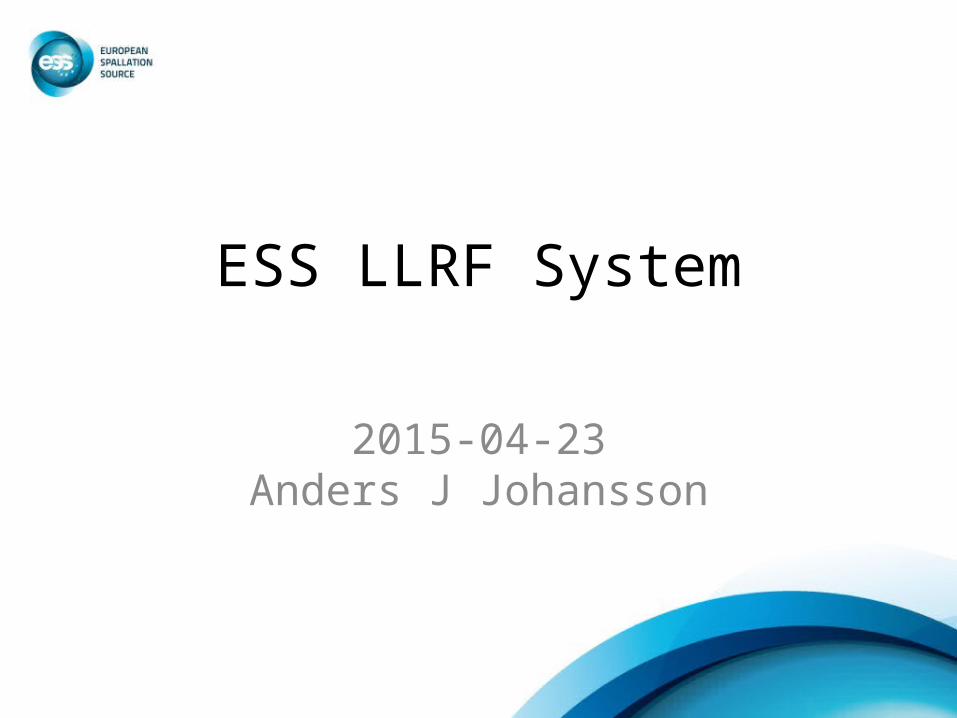
LLRF system
LLRF system:PI- controller
Master Oscillator
Phase Reference Clk 352.21 MHz
Amplifier(Klystron, Tetrode)
Pre-Amp
Load
Cavity
Circulator
PSU(Modulator)Power Grid
4 5
1
3 6 7
9
10
2
8
I
Pz Ctrl
Motor CtrlSlow Tuner
M
LLRF system:Motion control
LLRF system:Monitoring & Storing
1 … 10
Warning/ Errors
U
Design concept
• Digital implementation of fast control in FPGA• Modular design for simple maintenace• Modular design for large volume procurement• Redundant design for availability
• Downconversion at 352 MHz
5
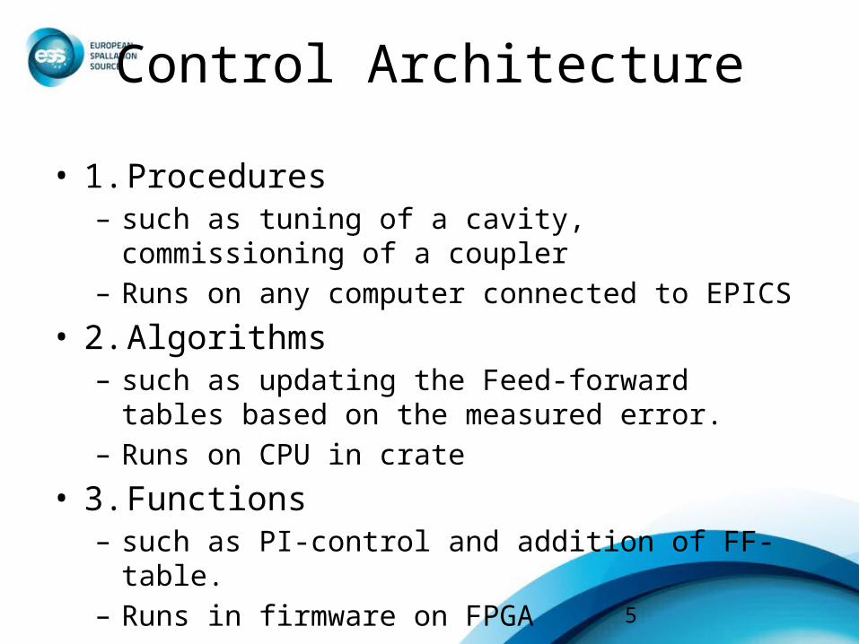
Control Architecture
• 1. Procedures– such as tuning of a cavity, commissioning of a coupler– Runs on any computer connected to EPICS
• 2. Algorithms– such as updating the Feed-forward tables based on the
measured error.– Runs on CPU in crate
• 3. Functions– such as PI-control and addition of FF-table.– Runs in firmware on FPGA

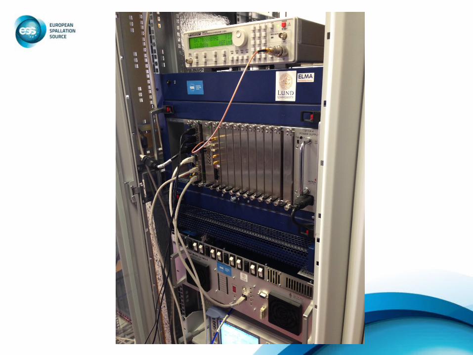
Warm LinacRack layout illustration
7
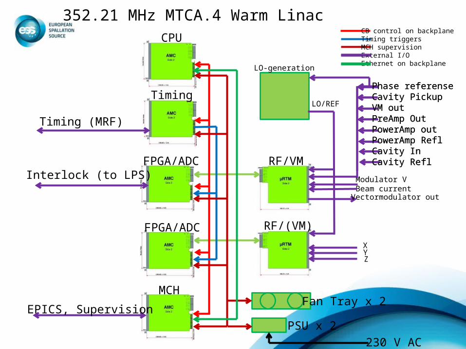
FPGA/ADC
RF/(VM)FPGA/ADC
RF/VM
CPU
Timing
Timing (MRF)
MCH
EPICS, Supervision
Modulator V Beam currentVectormodulator out
XYZ
Phase referenseCavity PickupVM outPreAmp OutPowerAmp outPowerAmp ReflCavity InCavity Refl
Fan Tray x 2
PSU x 2
Interlock (to LPS)
352.21 MHz MTCA.4 Warm LinacCB control on backplaneTiming triggersMCH supervisionExternal I/OEthernet on backplane
230 V AC
Phase referenseCavity PickupVM outPreAmp OutPowerAmp outPowerAmp ReflCavity InCavity Refl
LO-generation
LO/REF
9
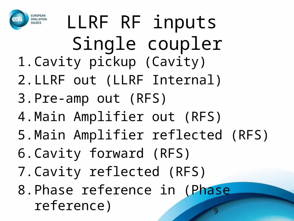
LLRF RF inputs Single coupler
1. Cavity pickup (Cavity)2. LLRF out (LLRF Internal)3. Pre-amp out (RFS)4. Main Amplifier out (RFS)5. Main Amplifier reflected (RFS)6. Cavity forward (RFS)7. Cavity reflected (RFS)8. Phase reference in (Phase reference)
10
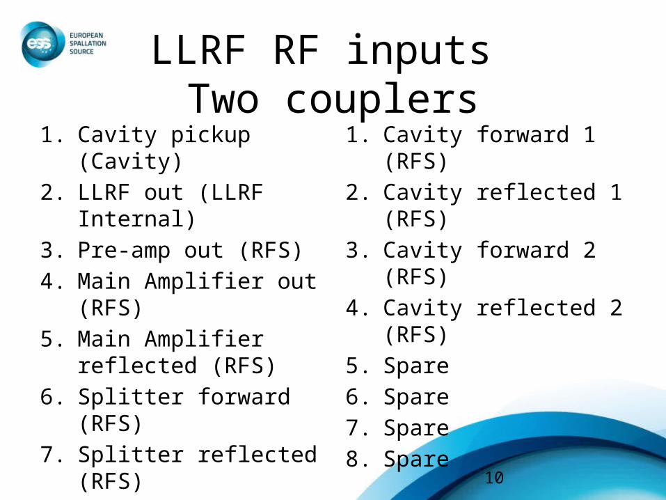
LLRF RF inputs Two couplers
1. Cavity pickup (Cavity)2. LLRF out (LLRF Internal)3. Pre-amp out (RFS)4. Main Amplifier out (RFS)5. Main Amplifier reflected
(RFS)6. Splitter forward (RFS)7. Splitter reflected (RFS)8. Phase reference in (Phase
reference)
1. Cavity forward 1 (RFS)2. Cavity reflected 1 (RFS)3. Cavity forward 2 (RFS)4. Cavity reflected 2 (RFS)5. Spare6. Spare7. Spare8. Spare
11
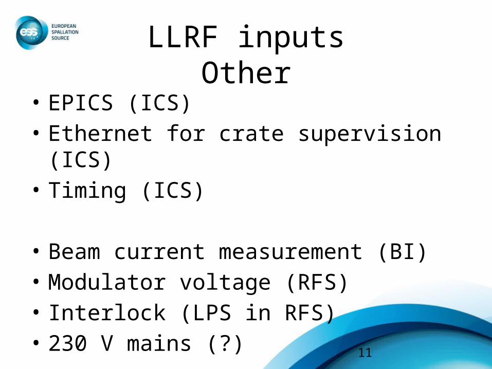
LLRF inputsOther
• EPICS (ICS)• Ethernet for crate supervision (ICS)• Timing (ICS)
• Beam current measurement (BI)• Modulator voltage (RFS)• Interlock (LPS in RFS)• 230 V mains (?)
12
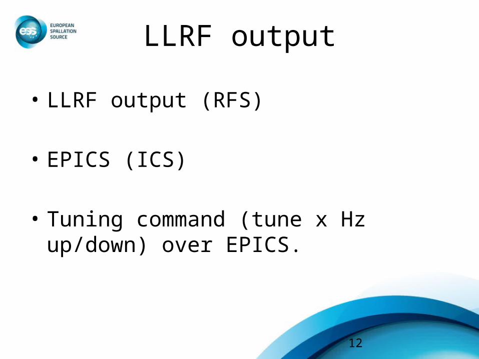
LLRF output
• LLRF output (RFS)
• EPICS (ICS)
• Tuning command (tune x Hz up/down) over EPICS.
13
Motion ControlBaseline interface
• Cavity WPs are responsible for protecting the cavities against harmful commands
• LLRF calculates necessary tuning adjustments
• Adjustments are sent over EPICS to be executed.
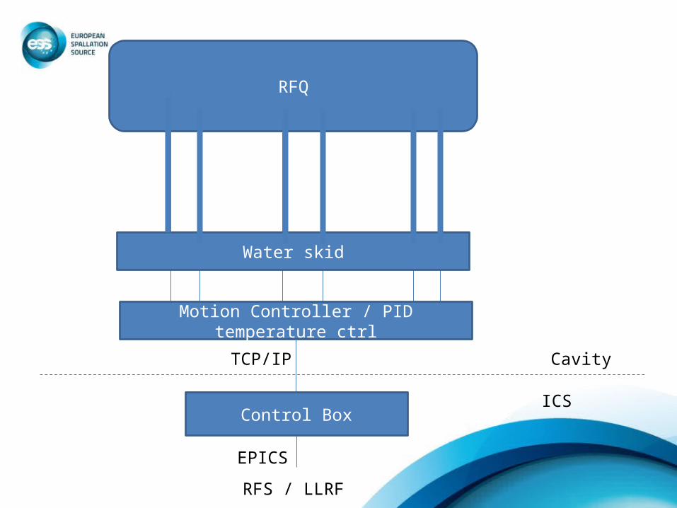
RFQ
Motion Controller / PID temperature ctrl
CavityTCP/IP
Control BoxICS
EPICS
Water skid
RFS / LLRF
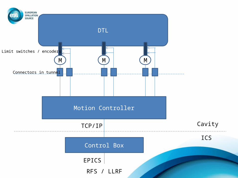
DTL
M M M
Motion Controller
Connectors in tunnel
CavityTCP/IP
Control BoxICS
EPICS
Limit switches / encoders
RFS / LLRF
16
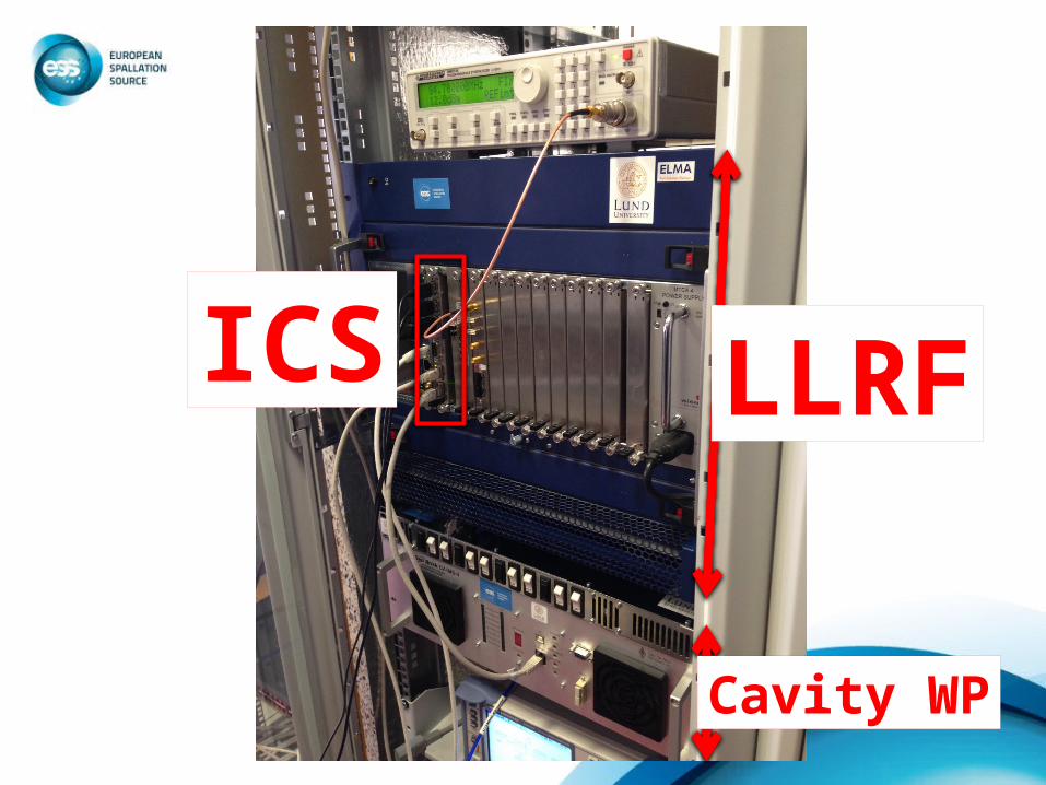
LLRF
Cavity WP
ICS
17
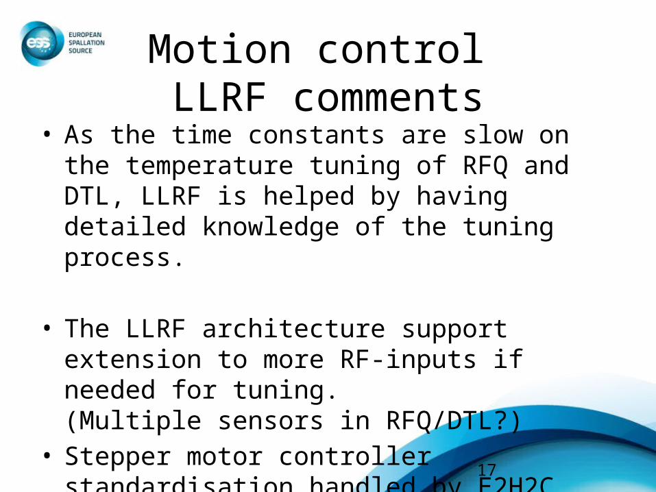
Motion control LLRF comments
• As the time constants are slow on the temperature tuning of RFQ and DTL, LLRF is helped by having detailed knowledge of the tuning process.
• The LLRF architecture support extension to more RF-inputs if needed for tuning. (Multiple sensors in RFQ/DTL?)
• Stepper motor controller standardisation handled by E2H2C.

18
COMPONENTS AND LAYOUT

Baseline Layout
• Crate for 1 buncher cavity
PSU PSU
MCH CPU Timing
LLRF
ADCFPGA+RTM
1 2 3 4 5 6 7 8 9 10 11 12
Baseline Layout
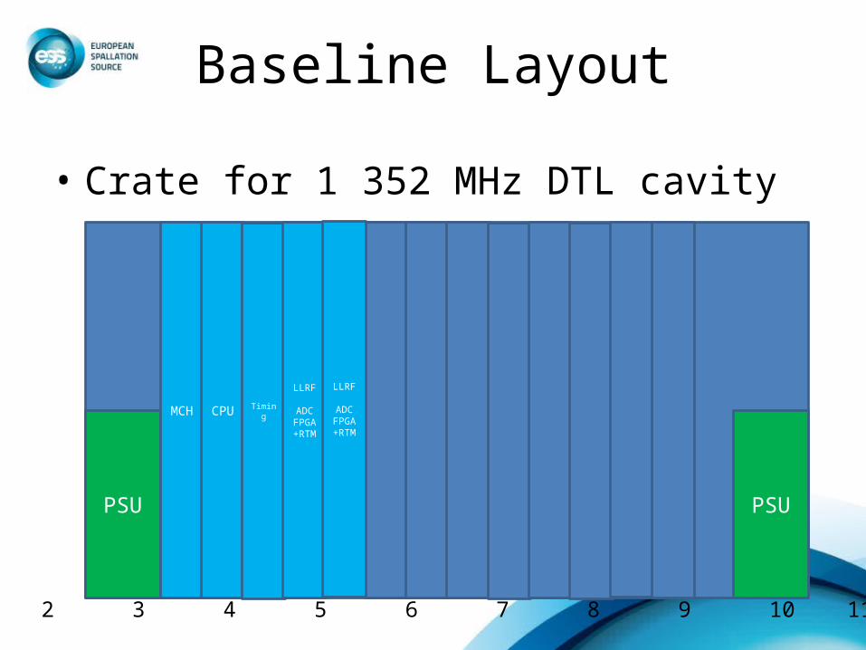
• Crate for 1 352 MHz DTL cavity
PSU PSU
MCH CPU Timing
LLRF
ADCFPGA+RTM
1 2 3 4 5 6 7 8 9 10 11 12
LLRF
ADCFPGA+RTM
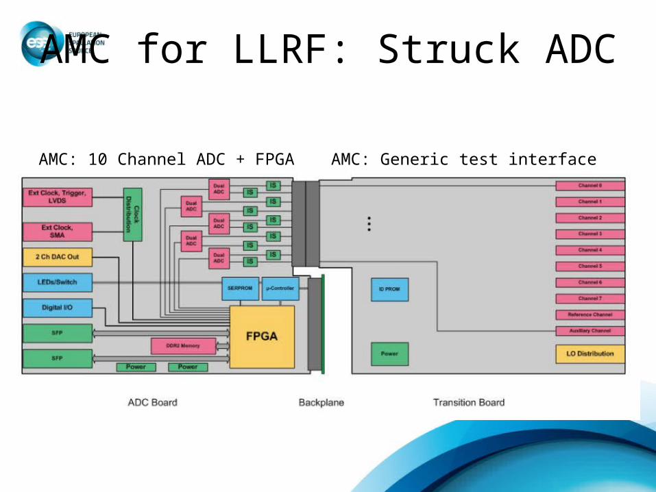
AMC for LLRF: Struck ADC
AMC: 10 Channel ADC + FPGA AMC: Generic test interface