Embed Size (px)
DESCRIPTION
manometros y sus especificaciones tecnicas
Citation preview
Bulletin P-DM-1100
DWYER INSTRUMENTS, INC. Phone: 219/879-8000 www.dwyer-inst.com
P.O. BOX 373 • MICHIGAN CITY, INDIANA 46360, U.S.A. Fax: 219/872-9057 e-mail: [email protected]
Specifications - Installation and Operating Instructions
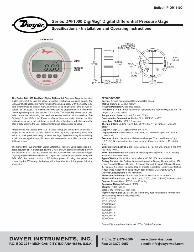
Series DM-1000 DigiMag® Digital Differential Pressure Gage
The Series DM-1000 DigiMag® Digital Differential Pressure Gage is the ideal
digital instrument to take the place of analog mechanical pressure gages. The
DigiMag® Digital Gages are more versatile than analog gages with their ability to be
field-programmed to display many commonly used engineering units as well as
percent of full scale. The Series DM-1000 can be programmed in 8 commonly
used engineering units plus percent of full scale. This capability allows quick units
selection on site, eliminating the need to calculate various unit conversions. The
DigiMag® Digital Differential Pressure Gages have an added feature for filter
applications where a set point can be input where the display will blink when the
filter is dirty, alerting the user that a maintenance action needs to occur.
Programming the Series DM-1000 is easy using the menu key to access 4
simplified menus which provide access to: Security level; engineering units; filter
set point; view peak and valley process readings; digital damping for smoothing
erratic process applications; display update to conserve battery life; zero and span
field calibration.
The Series DM-1000 DigiMag® Digital Differential Pressure Gage possesses a full
scale accuracy of 1% on ranges down to 2˝ w.c. and 2% accuracy down to the very
low ranges of 1” to 0.25" w.c. Models are also available with bi-directional ranges.
DigiMag® Digital Differential Pressure Gages offer power versatility by working with
9-24 VDC line power or simply 9V battery power. If using line power and
connecting the 9V battery, the battery will act as a back-up if line power is lost or
interrupted.
SPECIFICATIONS
Service: Air and non-combustible, compatible gases.
Wetted Materials: Consult factory.
Housing Materials: Glass filled plastic.
Accuracy: ±1% F.S. including linearity, hysteresis and repeatability; ±2% F.S. for
ranges 1˝ w.c. and below.
Temperature Limits: 0 to 140°F (-18 to 60°C).
Compensated Temperature Limits: 32 to 122°F (0 to 50°C).
Long Term Stability: ±1% F.S. per year.
Thermal Effect: ±0.05% F.S./°F typ.; ±0.10% F.S./°F for ranges 1˝ w.c. and
below.
Display: 4-digit LCD (Digits: 0.60˝H x 0.33˝W).
Display Update: Selectable for 1 second to 10 minutes or update only from
button push.
Pressure Limits: Normal and bi-directional ranges 5˝ w.c. and lower = 2 psi
(13.7 kPa); Normal and bi-directional ranges 10˝ w.c. and higher = 11 psi (75
kPa).
Selectable Engineering Units: in w.c., psi, kPa, Pa, mm w.c., mBar, in Hg, mm
Hg, FS (0-100%).
Power Requirements: 9V battery or external power supply 9-24 VDC. Battery
included but not connected.
Type of Battery: 9V alkaline battery (Duracell® PC 1604 or equivalent).
Battery Service Life: Battery life depending on the Display Update setting: 150
hours (typical) if Display Update = 1 second; 9 month (typical) if Display Update =
10 minutes; 1.5 years (typical) if Display Update is disabled. Battery may last up
to four times longer when using lithium-based battery ULTRALIFE U9VL-J.
Current Consumption: 5 mA maximum.
Electrical Connections: Removable terminal block for 16 to 26 AWG.
Electrical Entry: Cable gland for 0.114 to 0.250˝ (2.9 to 6.4 mm) diameter cable.
Process Connections: 1/8˝ (3 mm) ID tubing.
Enclosure Rating: NEMA 4X (IP66).
Weight: 1.18 lb (535 g).
Size: 5˝ (127 mm) O.D. front face.
Agency Approvals: CE, EN 61326-1 [Immunity Test Requirement for Industrial
Environments] with the following SPEC:
IEC 61000-3-2
IEC 61000-3-3
IEC61000-4-2
IEC61000-4-3
IEC61000-4-4
IEC61000-4-5
IEC61000-4-6
IEC61000-4-11
Duracell® is a registered trademark of The Gillette Company.
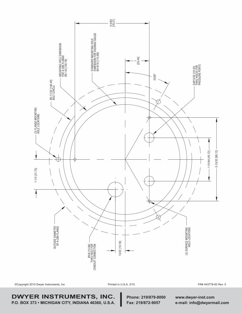
4-31/64[113.89]
3X1/8[3.30]1-59/64
[48.89]17/64[6.91]
Ø5[127.00]
PRESSURECONNECTIONS
21/64 [8.59] LONG
3-5/64[78.27]
1[25.44]
3-15/32[88.12]
Ø13/64[5.18]
Ø25/64[10.03]
INSTALLATION
Mounting
A vertical position required. That is the position in which all standard models are
calibrated at the factory. Provide a 4-9/16˝ diameter opening in panel. Insert gage
and secure in place with provided screws and adapters.
Included Accessories:
Mounting lugs – 3
6-20 x 2-1/2 screws – 3
4-20 x 3/8 screws – 3 (mounting hole depth is 3/8˝ [9.53])
Cable gland – 1
Pressure Connections
Two integral tubing connections are provided on the back of the gage. They are
sized to fit 3/16˝ (4.8 mm) I.D. x 5/16˝ (7.9 mm) O.D. flexible PVC tubing. To
measure single positive pressure, connect tubing to the + port and vent the – port
to atmosphere. To measure single negative pressure (vacuum), connect tubing to
the – port and vent the + port to atmosphere. To measure differential pressure,
connect higher pressure to the + port and lower pressure to the – port. Be sure the
pressure rating of the tubing exceeds that of the operating ranges.
Electrical Connections
A 9V battery or an external power supply 9-24 VDC can be used to power the unit.
If both battery and external power supply are connected, the battery will work as
back up power.
Battery Installation
The unit is shipped with a separate 9V alkaline battery. Remove the unit’s top back
cover, do not remove bottom cover. Connect the 9V battery to the battery holder as
shown in Figure 1. Replace top back cover and tighten screws to 2 ±.25 in. lbs.
External Power Supply Installation
Remove the unit’s back cover then connect the external power supply to the
terminal block as shown in Figure 1.
OPERATING INSTRUCTIONS
Key Functions
Home Position
Function
Allows access to the
menus
Displays pressure
readings instantly
(rAtE KEY MODE only)
Displays full scale
range of unit
Main Menu
Function
Return to home
position
Sequences through
menus
Sequences through
menus
Enter into SUB
MENU
Sub Menu
Function
Return to previous
menu
Increments a value
Decrements a value
Changes a value or
setting. Press
ENTER and display
will blink. Adjust with
UP or DOWN
arrows. Press
ENTER to store.
Display will stop
blinking.
Ø5/8 [15.88]THRU HOLE FOR
ONDUIT CONNECTION
OUTSIDE DIAMETEROF A-286 FLANGE
1-1/4 [31.75] (3) FLANGE MOUNTINGHOLE LOCATIONS
Ø B
FIGURE 1
Menu
Up Arrow
Down Arrow
Enter
POWER MUST BE OFF WHILE WIRING CONNECTIONS
ARE BEING MADE. DO NOT EXCEED SPECIFIED SUPPLY
VOLTAGE RATINGS. PERMANENT DAMAGE NOT COVERED BY WARRANTY
WILL RESULT.
CAUTION
Menu Map
MAIN MENU PROGRAMMING INSTRUCTIONS
(Upper Right Display Reads MENU)
Security Menu: SECr-MENU
Lock out access to all menus or lock out access to all menus except Auto-Zero
function (Auto-ZERO).
Operation Menu: OPEr-MENU
Select the measurement type – pressure, velocity or flow and corresponding
engineering units (Velocity and flow are not available for Model DM-1100).
Display Menu: diS-MENU
Monitor and adjust display related settings: Filter type, filter point, dampening,
display update, peak and valley.
Advanced Menu: AdU-MENU
Perform auto-zero or full-scale calibration.
SECURITY MENU: SECR-MENU
With the gage reading pressure (home position), press and hold the MENU key
until the Security MENU is displayed. Press the E key to show the security SUB
MENU SECr–0001. When the security SUB MENU is selected, the present
security level is displayed in the upper right hand display. To change the security
level, adjust the number displayed to the number shown in the following table for
the desired security level.
The password values shown in the table cannot be altered, so retain a copy of
these pages for future reference.
OPERATION MENU: OPER-MENU
With the gage reading a numerical value (home position), press and hold the
MENU key until the Security MENU is displayed. Press the q key to show the
OPEr-MENU. Press the E key to show the Operation SUB MENUS.
The Operation SUB MENUS for Series DM-1100 is PrES–INWC (Pressure–Unit)
PRESSURE SUB MENU: PRES – INWC
PrES – INWC: Pressure – inches of water column
With the LCD reading PrES – INWC, press the E key; the display will blink. Press
the q key to change the pressure unit then press the E key to save the desired
unit.
For pressure measurement, the following units are available:
INWC – Inches of water column MBAR – Millibar
PSI – Pounds per square inch INHG – Inches of mercury
KPA – Kilopascals MMHG – Millimeters of mercury
PA – Pascals FS – % of full scale
MMWC – Millimeters of water column
Security Level
Displayed
1
2
3
Access
All menus access
All menus locked except
the auto-zero function
All menus locked
Password Value
to Enter
10
90
111
TABLE 1 PRESSURE RANGE VS. AVAILABLE UNITS
NOTE: OFL (over flow) or UFL (under flow) will appear when the low and high
range levels have been exceeded by 10% F.S.
in w.c.
0.250
0.500
1.000
2.000
5.000
10.00
15.00
25.00
50.00
100.0
psi
–
–
–
–
0.181
0.361
0.543
0.903
1.806
3.613
kPa
0.062
0.124
0.249
0.498
1.245
2.491
3.738
6.227
12.45
24.91
Pa
62.20
124.5
249.1
498.2
1245
2491
3738
6227
–
–
mbar
0.622
1.245
2.492
4.982
12.45
24.91
37.38
62.27
124.5
249.1
mm w.c.
6.35
12.70
25.40
50.80
127.0
254.0
381.0
635.0
1270
2540
in Hg
–
–
–
–
0.368
0.736
1.104
1.839
3.678
7.355
mm Hg
0.467
0.934
1.868
3.736
9.34
18.68
28.02
46.71
93.42
186.8
% of
FS
100.0
100.0
100.0
100.0
100.0
100.0
100.0
100.0
100.0
100.0
Resolution
(in w.c.)
0.001
0.001
0.001
0.001
0.002
0.010
0.010
0.010
0.020
0.100
DISPLAY MENU: diS – MENU
With the gage reading a numerical value (home position), press and hold the
MENU key until the Security MENU is displayed. Press the q key until the LCD
shows diS – MENU. Press the E key to show the Display SUB MENUS.
FILTER TYPE SETTING
With the LCD reading FILt – OFF, press the E key; the display will blink. Press the
q key to change the filter type then press the E key to save the desired filter type.
FILt – OFF: Filter type = OFF. The filter function is disabled.
FILt – HIGH: Filter type = HIGH. The display blinks when pressure is greater than
the filter point.
FILt – LOW: Filter type - LOW. The display blinks when pressure is less than the
filter point.
FILTER POINT SETTING
With the LCD reading 0.00 – SPPT, press the E key; the display will blink. Press
the q key to change the filter point then press the E key to save the desired filter
point.
0.00 – SPPT: Filter point = 0.00. The filter point may be set to anywhere within the
range of the instrument.
DAMPING SETTING
With the LCD reading 1 – DAMP, press the E key; the display will blink. Press the
q key to change the damping level then press the E key to save the desired
damping level.
1 – DAMP: Damping level = 1. The damping level can be adjusted from 1 to 15.
Damping stabilizes the display from instabilities due to things such as vibration and
excessive pressure fluctuations. The damping function adjusts the amount of
readings that are averaged for each display update.
DISPLAY UPDATE SETTING
With the LCD reading rAtE – NORM, press the E key; the display will blink. Press
the q key to change the display update rate then press the E key to save the
desired display update rate.
rAtE – NORM: Display update = Normal (1 second).
The gage reads the process pressure and updates the LCD every second.
rAtE – 10: Display update = 10 minutes.
The gage reads the process pressure and updates the LCD every 10 minutes.
rAtE – KEY (On-Touch mode): Display update is disabled.
The gage reads the process pressure and updates the LCD whenever the p key
is pressed. If the p key is released, the LCD will hold and display the last pressure
reading.
NOTES:
1. Depending on the Display Update setting, the battery life is shown below:
-150 hours (typical) if Display Update is set for “Normal” 1 second update. rAtE-
NORM
-9 months (typical) if Display Update is set for 10 minutes. rAtE-10
-1.5 years (typical) if Display Update is disabled. rAtE-KEY
2. If the Display Update is set for 10 minutes or disabled (On-Touch mode), the
process pressure value can be read instantly by pressing and holding the p key
on the front panel. Also the LCD will automatically show “ALAr” if the filter point has
been exceeded.
PEAK AND VALLEY SETTING
100.0 – PEAK: Peak value = 100.0
The peak feature stores the highest pressure reading the instrument has measured
since the last reset or power up. At power up PEAK is reset to the present pressure
reading. To manually reset the PEAK value, press the E key while in the PEAK
SUB MENU.
0.0 – VALY: Valley value = 0.0
The valley feature stores the lowest pressure reading the instrument has measured
since the last reset or power up. At power up VALY is reset to the present pressure
reading. To manually reset the VALY value, press the E key while in the VALY SUB
MENU.
ADVANCED MENU: AdU – MENU
With the gage reading pressure (home position), press and hold the MENU key
until the Security MENU is displayed. Press the q key until the display shows the
AdU – MENU. Press the E key to show the advanced function SUB MENUS.
Auto ZERO: auto-zero
NOTE: For accurate calibration, DO NOT apply any pressure when
performing this function.
With the display reading Auto ZERO, release pressure to Zero then press the E
key; the display will blink. Press the E key again to complete the auto-zero.
CAL – SPAN: full-scale calibration
With the display reading CAL – FS, apply full-scale pressure then press the E key;
the display will blink. Press the E key again to save the full-scale calibration or
press the MENU key to cancel the calibration.
MAINTENANCE
This model is not field-serviceable and should be returned if repair is needed (field
repair should not be attempted and may void warranty). Be sure to include a brief
description of the problem plus any relevant application notes. Contact customer
service to receive a return goods authorization number before shipping.
DWYER INSTRUMENTS, INC. Phone: 219/879-8000 www.dwyer-inst.com
P.O. BOX 373 • MICHIGAN CITY, INDIANA 46360, U.S.A. Fax: 219/872-9057 e-mail: [email protected]
©Copyright 2015 Dwyer Instruments, Inc Printed in U.S.A. 2/15 FR# 443779-00 Rev. 5
3-5/
64[7
8.27
]
STAN
DARD
MOU
NTIN
G HO
LEDI
MEN
SION
FOR
DIG
IMAG
GAU
GEØ4
-9/1
6 [1
15.8
9]
1[2
5.44
]
2X30
°
2xØ1
3/32
[10.
32]
THRU
HOL
ES F
OR
PRES
SURE
POR
TS
1-51
/64
[45.
72]
3-15
/32
[88.
12]
(3) S
URFA
CE M
OUNT
ING
HOLE
LOC
ATIO
NS
13/3
2 [1
0.16
]
Ø5/8
[15.
88]
THRU
HOL
E FO
RCO
NDUI
T CO
NNEC
TIONOU
TSID
E DI
AMET
EROF
A-2
86 F
LANG
E
1-1/
4 [3
1.75
](3
) FLA
NGE
MOU
NTIN
GHO
LE L
OCAT
IONS
Ø5-1
7/32
[140
.49]
BOLT
CIR
CLE
MOU
NTIN
G HO
LE D
IMEN
SION
FOR
A-28
6 FL
ANGE
Ø5-1
/8 [1
30.1
8]