Embed Size (px)
Citation preview

This is an Open Access article distributed under the terms of the Creative Commons Attribution License 4.0, which permits unrestricted use, distribution, and reproduction in any medium, provided the original work is properly cited.
BIO Web of Conferences 5, 01015 (2015)DOI: 10.1051/bioconf/20150501015© Owned by the authors, published by EDP Sciences, 2015
1. IntroductionThe high spatial and temporal variability of an agriculture exploration with specific demands, such as a vineyard, rep-resents the opportunity to use variable rate technologies, such as the methodologies of precision viticulture. Among technologies used to obtain maps from vigour and vegeta-tive state of plants, remote detection is one of the most common. This type of technology is based on computer vision techniques and typically combines the use of red and infrared bands to create indexes of vigour, vegetative state or others. Although widely used, remote detection has several important limitations. For instance, the need to validate in the field maps obtained from remote detec-tion since usually images communicate only information from the top and not from the entire canopy. In addition, depending on the resolution and time of the day, among other factors, information carried by the image may repre-sent the behaviour of the vineyard and also of the vegeta-tion between trellises.
With the advance of integrated technologies based on robotics, solutions supported by UAVs started to appear in the market. However, the operators of these systems must have a high degree of specialization as they need to command the UAV and they have to develop tasks with different softwares, responsible for specific parts of the solution.
The system presented in this work, developed by ENERMETER during the Portuguese project QREN num-ber 24792, is supported by computer vision and georefer-enced sensors. The resulting system allows for acquisition of 100% of the target area of the vineyard and of entire vines’ canopies, generating high resolution maps of the whole leaf surface without need for expertise in navigation or software. The operator can access all acquired images and, so, he may perform remote validation of generated maps.
2. Remote detection – state of the artTo ensure proper management of human and equipment resources in vineyard production and, consequently, for high quality wine production, it is essential to efficiently manage at different phenological stages of the growth cycle. Those are highly related with vine growth and with quality of the grape.
Remote detection is one of the techniques used to help predicting vineyard growth, through the use of aer-ial images obtained from multispectral sensors, typically acquired from RGB and from infrared (IR) cameras [1]. Image acquisition can be done through the use of satellite images or through images acquired by airplanes. In last years, acquisition by airplanes has been replaced or com-plemented with Unmanned Aerial Vehicles (UAV).
Satellite images have low spatial and temporal reso-lutions and high cost. On the contrary, remote detection performed from aerial platforms has higher resolution, both spatial and temporal. The former can be from a few centimeters to one meter [3–7]. Using an aerial vehicle, temporal resolution is basically dependent on needs and weather conditions.
With the advance of robotics, specifically of mobile robots, guidance and automatic trajectories generation, new methods for acquiring remote images have appeared, specifically those based on UAVs. Some of these UAVs have coupled the necessary technology to perform remote detection: visible and infrared cameras and GPS. These units can obtain images with even higher resolution than aerial vehicles but at low cost.
From remote detection images it is possible to quantify a set of indexes that can be used to predict the vigour of the vine, such as [8,4,9]:
• NDVI–“NormalisedDifferenceVegetationIndex”;• PCD–“PlantCellDensity”;• RVI–“RatioVegetationIndex.
ESOVYM – Enermeter’s system of vineyard monitoring
Manuel João Ferreira1, André Pinho1, António Graça2, and Teresa Martins1
1 ENERMETER, Computer Vision Department, Celeirós, Braga, Portugal2 Sogrape Vinhos S.A., Research and Development Department, Aldeia Nova, Avintes, Portugal
Abstract. This paper presents the results of the national project QREN number 24792 that consisted on the development of a mobile unit for acquiring and processing georeferenced images, to be applied in viticulture. The system has high resolution (approximately 2 cm2) and moves through the entire surface of the vineyard and of the field portions. During displacement, this unit performs simultaneously the acquisition of images (in the visible and infrared spectrum) of left and right trellis for process-ing, analysis and visualization. The mobile unit is not autonomous, which means that it is linked to a 4 × 4 moto or to any agri-culture tractor. It is easy to operate and has low cost, which allows its use at different stages of vineyard production.
BIO Web of Conferences
01015-p.2
From these indicators it is possible to identify areas inside the vineyard needing different intervention procedures during the vine growth, making use of variable rate meth-odology [3].
In the literature, there are several works [10,11] that seek correlation between indicators obtained by remote sensing images and productive factors, such as leaf area and production of grapevines. High correlations allow to predict the outcome of production and to implement better management of surrounding resources.
3. System architectureThe system architecture must be able to face the actual limitations of remote detection techniques, which are the following:
• informationthatisdeliveredtothevineyardmanageris limited to the top of the canopy, which can be con-fused with soil, depending on the resolution of the sys-temandonthesoilcover;
• indexesmaysuggesttheexistenceofstressonthevine,but using only the aerial image is not possible to iden-tifywhichtypeofstress;itisnecessarytogotovine-yardsforfurtheranalysis;
• indicators obtained by aerial images may not reflectthe true state of the vineyard in situations of very dense orsparsedensityofleafarea;
• from currently used indicators it is difficult to infer(low correlations), with accuracy, other factors such as height of the vegetative hedge, leaf area, number and densityofgrapevines;
• finally, another important factor is related to opera-tion cost and logistics of current systems. These two aspects lead to collect aerial information only on vérai-sonstage,insteadoffloweringandmaturationstages.
Specification and development of an information collec-tion system of the entire vegetative hedge of the vineyard and all trellis of vines were based on the above-mentioned issues. So, the system was specified to be coupled to a 4 × 4 quad-bike or to any agricultural tractor, and can be operated while performing other activities in the vineyard.
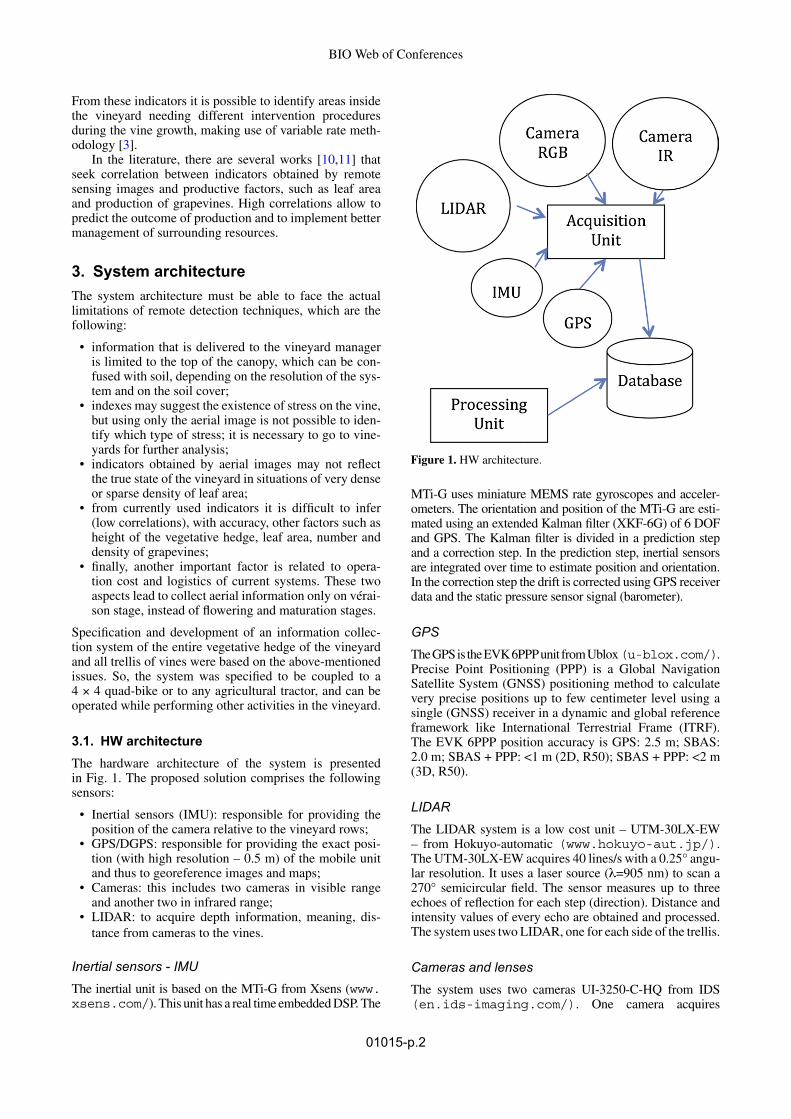
3.1. HW architectureThe hardware architecture of the system is presented in Fig. 1. The proposed solution comprises the following sensors:
• Inertial sensors (IMU): responsible forproviding thepositionofthecamerarelativetothevineyardrows;
• GPS/DGPS:responsibleforprovidingtheexactposi-tion (with high resolution – 0.5 m) of the mobile unit andthustogeoreferenceimagesandmaps;
• Cameras: this includes two cameras in visible rangeandanothertwoininfraredrange;
• LIDAR: to acquire depth information, meaning, dis-tance from cameras to the vines.
Inertial sensors - IMUThe inertial unit is based on the MTi-G from Xsens (www.xsens.com/). This unit has a real time embedded DSP. The
MTi-G uses miniature MEMS rate gyroscopes and acceler-ometers. The orientation and position of the MTi-G are esti-mated using an extended Kalman filter (XKF-6G) of 6 DOF and GPS. The Kalman filter is divided in a prediction step and a correction step. In the prediction step, inertial sensors are integrated over time to estimate position and orientation. In the correction step the drift is corrected using GPS receiver data and the static pressure sensor signal (barometer).
GPSThe GPS is the EVK 6PPP unit from Ublox (u-blox.com/). Precise Point Positioning (PPP) is a Global Navigation Satellite System (GNSS) positioning method to calculate very precise positions up to few centimeter level using a single (GNSS) receiver in a dynamic and global reference framework like International Terrestrial Frame (ITRF). TheEVK6PPPpositionaccuracyisGPS:2.5m;SBAS:2.0m;SBAS+PPP:<1m(2D,R50);SBAS+PPP:<2m(3D, R50).
LIDARTheLIDARsystemisalowcostunit–UTM-30LX-EW– from Hokuyo-automatic (www.hokuyo-aut.jp/). TheUTM-30LX-EWacquires40lines/switha0.25°angu-lar resolution. It uses a laser source (λ=905 nm) to scan a 270° semicircularfield.The sensormeasuresup to threeechoesofreflectionforeachstep(direction).Distanceandintensity values of every echo are obtained and processed. ThesystemusestwoLIDAR,oneforeachsideofthetrellis.
Cameras and lensesThe system uses two cameras UI-3250-C-HQ from IDS (en.ids-imaging.com/). One camera acquires
Figure 1. HW architecture.

38th World Congress of Vine and Wine
01015-p.3
images in the visible spectrum, while the other acquires images in the infrared band. In order to obtain IR images, the IR filter was removed from the camera. Combining both cameras a multispectral system was accomplished. Each camera has a resolution of 1600 × 1200 pixels (19 Mpixels) at a frame rate of 60 fps. Also, each one has an HR (high res-olution) lens with a focal distance of 3.5 mm. These lenses have high angular angle but with low distortion. The system uses two sets of cameras, one for each side of the trellis.
Processing unitThe processing unit has an architecture based on desktop PC with Windows 7 Pro. The unit has an i7 processor with 16GBofmemory;onedisk(fordatabase)SSDof2TB.
3.2. SW architectureTo achieve the system goals, the methodological approach included the development of the following algorithms/modules (Fig. 2):
• modulesforHWcontrolandrawdataacquisition;• module for data filtering from raw data to georefer-
enceddata;• moduleforpost-processing;• moduleforclassification.
The first block of Fig. 2 controls all data acquisition proce-duresforLIDAR,IMU,GPSandCameras.Thefirststageconsisted in the development of procedures for extract-ing information from inertial sensors and GPS. Then, development continued with tools for image acquisition. This block acquires and saves data at maximum temporal
resolution of the system: 40 acquisitions per second. All data are stored for further processing and analysis.
The phase devoted to sensorial fusion (block 2) led to ageoreferencednetworkof“vineyard”andtoaprojectivematrix that allocates all images in the same reference. It uses raw information (IMU data plus raw GPS data) to cor-rect GPS data and to generate the point cloud (obtained by LIDAR)correctedintermsofposition(GPS)andinatti-tude (IMU). Each of the acquired images (RGB and IR) is pre-processed to eliminate noise generated by movement of the cameras and also to establish the reference to the corresponding line of LIDAR. This leads to point cloudand image, which is corrected in terms of the path made by the mobile vehicle.
In the next block (post-processing module) the pano-ramic image of the height of the vegetative hedge is gener-ated. To do this, initially, incoherent lines of images and point clouds are discharged, using Kalman filters. After this, the mosaic image is constructed using the geo-ref-erenced tags and image registration algorithms. At this point, each portion of the next image fits with the previous image mosaic.
The architecture proceeded with development of algo-rithms for extracting information that is relevant to create vigour maps. Inputs for this map generation module are the panoramic image and all georeferenced images that prompted it. Through an automatic analysis of images, the system creates standard georeferenced maps: NDVI –NormalizedDifferenceVegetation Index;PCD–PlantCellDensity;PVR–PhotosyntheticVigourratio;PPR–Plant Pigment Ratio. Besides these indicators, the follow-ingitemsareobtained:recognitionofleafarea;heightofthevegetativehedge;identificationofgrapevines,allowingfor the determination of the ratio between leaf area (m2/ha) andgrapeproduction(kg/ha);leafareaindex.
4. ResultsThe specific goal of the project was the development of a mobile unit, which performs simultaneous image acquisi-tion (in the visible and near infrared), from the left and right trellis, for further processing, analysis and visualization. In this way, 100% of the vineyard area of a field is acquired, creating a panoramic view of the trellis, with high resolu-tion (in the order of 2 cm) as it goes along vine rows.
In order to evaluate results, the prototype was cou-pled to a quad bike (Fig. 3). Data collection tests were performed in three very different types of terrains and vineyards in Portugal, one in Minho region (Vinho Verde appellation), one in Douro region (Port and Douro appella-tions) and another in Beiras region (Bairrada appellation).
Figure 4 presents a sequence of three images acquired by the RGB camera and Fig. 5 a panoramic image created using a sequence of these images plus 50 images and the sensorfusion:IMU,GPSandLIDAR.
In the map generation module (graphical user interface in Fig. 6) the operator has access to high-level information (high degree of abstraction): the predefined georeferenced maps. He can also go down in the level of abstraction to more detailed information (sequence of acquired images of the vineyards). In this way, a multiresolution analysis and display is available, as can be seen in Fig. 7.Figure 2. SW architecture.

BIO Web of Conferences
01015-p.4
Figure 4. Sequence of 3 acquired images.
Figure 6. GUI interface.
Figure 7. Multiresolution visualization approach.
Figure 8. Navigation interface between trellises.
Figure 3. Prototype coupled to a 4 × 4 moto.
At the intermediate level view (panoramic image) the operator can browse different trellises of vines (Fig. 8).
The panoramic image (Figs. 5 and 8) can be displayed in IR or RGB bands. The data band appearing on the top of the panoramic image (Fig. 8) corresponds to the selected
Figure 5. Panoramic image (bottom).

38th World Congress of Vine and Wine
01015-p.5
information, i.e. the integration of the column in the vis-ible(RGB);ortheinformationintheIRband,orthequan-tified indicators such as PVR.
As an example, Fig. 9 shows the panoramic image and the respective PVR, PPR, and the leaf surface index indi-cator bands.
5. ConclusionThe proposed system consists of an innovative solution able to generate georeferenced maps of an entire vine-yard’s canopy surface, based on computer vision tech-niques, with high resolution, in the order of cm2. An important advantage lies on its ease operation and low cost, which allows use in different stages of production. Also, in terms of function, the system offers the possibility to obtain, remotely, vital data about the state of vineyard production.
References [1] S. Pires, Detecção Remota para aplicações em
Viticultura de Precisão no Alentejo. Revista da Associação Portuguesa de Enologia, N.os 51/52 (2008)
[2] D.Lamb,A.Hall,J.Louis,Airboneremotingsensingof vines canopy variability and productivity. Australian Grapegrower & Winemaker. Annual Technical (2001)
[3] T.Proffit,R.Bramley,D.Lamb,E.Winter,PrecisionViticulture. A new era in vineyard management and wine production. Winetitles, Adelaide (2006)
[4] R.G.V. Bramley, Measuring within vineyard varia-bility in yield and quality attributes. Vineyard moni-toring and management beyond. Wagga (2000)
[5] R.G.V. Bramley, D.W. Lamb, Making sense ofvineyard variability in Australia. Occasional report nº14. Fertilizer and lime research centre, Massey University, Palmerston Nort (2001)
[6] R.G.V.Bramley,D.W.Lamb,Makingsenseofvine-yard variability in Australia. Precision Viticulture, edited by R. Ortega, A. Esser. Proceedings of an international symposium held as part of the IX CongresoLatinoamericanodeViticulturaeEnologia,Chile. Centro de Agricultura de Precisión (CAPUC), Pontificia Universidad Católica de Chile (2003)
[7] R.G.V. Bramley, R.P. Hamilton, Understanding vari-ability in winegrape production systems. Australian Journal of Grape and Wine Research. 10: 32–45 (2004)
[8] A.Hall,D.W.Lamb,B.Holzapfel,J.Louis,Opticalremote sensing applications in viticulture - a review. Australian Journal of Grape and Wine Research, 8: 36–47 (2002)
[9] R, Ortega, A. Esser, Viticultura de Precisión: Funda-mentos, aplicaciones y oportunidades en Chile. PontificiaUniversidadCatólicadeChile.;1–10(2002)
[10] P. Sereno, Viticultura de precisão: Utilização da deteção remota no estudo da variabilidade espacial dovigor,produçãoequalidade,castas“SYRAH”E“TOURIGA FRANCA” Universidade Técnica deLisboa,Masterthesis,Lisboa(2009)
[11] C. Pereira, Inspecção visual em aplicações de viti-cultura de precisão, Universidade de Trás-os Montes e Alto Douro, Master thesis, vila real (2009)
Figure 9. Panoramic image and respective PVR, PPR, and the leaf surface indicators.