Embed Size (px)
Citation preview

The Welding Simulation Solution
Courtesy WAGON Automotive GmbH
ESI GROUP

February 2006
Copyright ES I GROUP
The Welding Simulation Solution
SUMMARY OF THE WELDING OFFER
ESI GROUP

The Welding S imulation Solution i ES I GROUP © 2006 ES I Group (released: April-06)
CONTENTS
CONTENTS Getting Value 4
Industries Objectives ---------------------------------------------------------------------- 4 Industries Benefits ------------------------------------------------------------------------- 4 Improvement of the Performance and Quality of the Product ----------------- 6 Distortion Engineering – Cost Reduction -------------------------------------------- 7 Position in the Product Cycle ----------------------------------------------------------- 9 Beneficiaries ------------------------------------------------------------------------------ 10 The Team Behind „The Welding S imulation Solution‟ -------------------------- 11
Representative References 12 Industry ------------------------------------------------------------------------------------- 12 University and Institutes --------------------------------------------------------------- 12 General ES I GROUP ------------------------------------------------------------------- 12
Applications 13 Transient Welding ----------------------------------------------------------------------- 13 Steady S tate Welding------------------------------------------------------------------- 28 Macro Bead Welding -------------------------------------------------------------------- 29 Welding Assembly ----------------------------------------------------------------------- 31 Friction Welding -------------------------------------------------------------------------- 40 Friction S tir Welding --------------------------------------------------------------------- 41 Spot Welding ------------------------------------------------------------------------------ 41
Scientific Work 48 What do the Experts Say -------------------------------------------------------------- 48 Applications ------------------------------------------------------------------------------- 51
Available Software Tools 70 Meshing – VISUAL MESH ------------------------------------------------------------ 70
Shell Meshing ---------------------------------------------------------------------------- 70 Shell-Solid-Meshing -------------------------------------------------------------------- 70 Solid-Meshing ---------------------------------------------------------------------------- 71 Automatic Shell Meshing -------------------------------------------------------------- 71 Automatic Link of Shell Components with Solid Welding J oints -------------- 72 How to Generate Quickly Meshes for Transient and Macro Step Welding S imulation -------------------------------------------------------------------- 72
Transient and Steady S tate Welding ----------------------------------------------- 75 Welding Wizard -------------------------------------------------------------------------- 75 Local Model Wizard --------------------------------------------------------------------- 76 Heat Source Fitting Tool --------------------------------------------------------------- 77 Hardness S imulation Wizard --------------------------------------------------------- 78 Metallurgical Parameters Fitting Tool ----------------------------------------------- 79 Multi-Pass Welding --------------------------------------------------------------------- 80 Spot Welding ----------------------------------------------------------------------------- 81 Friction Stir Welding -------------------------------------------------------------------- 84 Welding Material Databases ---------------------------------------------------------- 85 Check Box -------------------------------------------------------------------------------- 86
Macro STEP Welding ------------------------------------------------------------------- 90 The Macro Bead Advisor -------------------------------------------------------------- 90
Welding Assembly ----------------------------------------------------------------------- 91

ESI GROUP ii The Welding S imulation Solution (released: April-06) © 2006 ES I Group
CONTENTS
The Assembly Advisor ----------------------------------------------------------------- 91 PAM-ASSEMBLY Database Manager ------------------------------------------------- 92 PAM-ASSEMBLY --------------------------------------------------------------------------- 92
Available Engineering Tools 93 Toolbox CD-ROM ------------------------------------------------------------------------ 94 Engineering Guide ----------------------------------------------------------------------- 94 Examples CD-ROM --------------------------------------------------------------------- 94
Documentation 95 Welding User‟s Guide ------------------------------------------------------------------ 95 Knowledge Included -------------------------------------------------------------------- 96
Key Technology 97 S imulated Physics ----------------------------------------------------------------------- 97 Movement of Heat Sources along Weldlines ------------------------------------- 97 Removal of Material History ---------------------------------------------------------- 98 Material Properties Depending on Phases or Material S tatus --------------- 99 Volume Changes During Phase Transformations ---------------------------- 100 Phase Transformations of Hardenable S teel ----------------------------------- 102 Almgmn – Kinetics of Recrystallization ------------------------------------------ 103 Almgsi – Kinetics of Precipitates --------------------------------------------------- 104 Dedicated Mechanical Material Laws -------------------------------------------- 104 Mesh Independent Application of Properties ----------------------------------- 106 Chewing Gum Method for Filler Material ---------------------------------------- 106 Classic FEM Tools -------------------------------------------------------------------- 107 Fully Automatic Solver---------------------------------------------------------------- 107 Numerical S tability --------------------------------------------------------------------- 107 Linear System of Equations Solvers ---------------------------------------------- 108 Hardware Platforms ------------------------------------------------------------------- 108 Summary – Technical Features and Key Technology ----------------------- 109 Illustration – Technical Features and Key Technology ---------------------- 110
Chaining with Stamping and Crash Simulation 115 Chaining S tamping and Welding -------------------------------------------------- 115 Chaining Welding and Stamping -------------------------------------------------- 116 Chaining Welding and Crash ------------------------------------------------------- 116
Chaining with Fatigue and Structural Analysis 117 Basic Concept and Interface -------------------------------------------------------- 117
Welding-Assembly of Large Structures 118 Overview --------------------------------------------------------------------------------- 118 Basic Concept -------------------------------------------------------------------------- 119 Positioning in the Product and Process Workflow ---------------------------- 121 SYSWELD and PAM-ASSEMBLY - S imulation Solution for Welding Assembly ------------------------------------------------------------------------------- 122
A typical Workflow --------------------------------------------------------------------- 124
ESI Group Profile 130 Pioneering Virtual Engineering ----------------------------------------------------- 130

The Welding S imulation Solution iii ES I GROUP © 2006 ES I Group (released: April-06)
CONTENTS
ESI Group Consulting Services 134 Committing to Customers ----------------------------------------------------------- 134 Service offer - Welding --------------------------------------------------------------- 134
Training Courses 135 ES I Group Learning Solutions ------------------------------------------------------ 136 Worldwide Learning Centers ------------------------------------------------------- 137 Meshing Welding Applications ----------------------------------------------------- 138 Welding S imulation - Getting it Right --------------------------------------------- 139 Understanding the Material Background ---------------------------------------- 140 Understanding Numerical Parameters and Nonlinear Geometry --------- 141 How to Perform and Document Projects E ffectively -------------------------- 142 Welding Assembly S imulation ------------------------------------------------------ 143 Welding Assembly S imulation of Large Heavy Industry S tructures ------ 144 Stamping and Welding S imulation Coupling ----------------------------------- 145 Understanding the Theoretical Background of Welding S imulation ------ 146
ESI GROUP 4 SYSWELD®2006 (released: April-06) © 2006 ES I Group
Copyright ES I GROUP 4
GETTING VALUE
INDUSTRIES OBJECTIVES
The Industries objectives are
Market effectively
Reduce costs
Shorten time to market
Reduce downtime
Improve productivity
Increase efficiency
Improve profitability
Gain access to new, global markets
Enhance product quality and reliability
Introduce innovation
Reduce weight
Reduce scrap and rework
Avoid failure
The Welding Simulation Solution has been designed to get value with respect to the listed objectives, though computer modeling.
INDUSTRIES BENEFITS
Using ‘The Welding Simulation Solution’, you will be able to
Minimize production cost
Minimize structural weight
Minimize distortions (distortion engineering)
Minimize product risk in the earliest stage of the product development cycle
Master assembly problems
Ascertain the level & distribution of residual stresses
Control and minimize hardness and grain size in the FZ and HAZ

SYSWELD®2006 5 ES I GROUP © 2006 ES I Group (released: April-06)
Copyright ES I GROUP 5
Avoid cold cracks
‘The Welding Simulation Solution’ helps you to
Improve the product design
Identify better processes or materials
Meet procedure approvals
Meet product acceptance standards
Implement new production methodologies
Meet contract quality requirements
Your objective to provide the best product possible is achieved by simulation-based process design through
Improved understanding of the effects that lead to distortions and residual stresses
Subsequent optimisation of the product design and the manufacturing processes
A key feature of ‘The Welding Simulation Solution’ is the sensitivity analysis
Major influence: A change in the parameter of 10% leads to a change of 100% in results
Moderate influence: A change in the parameter of 10% leads to a change of 10% in results
Low influence: A change in the parameter of 10% leads to a change of 1% in results
The sensitivity parameters studied are
Welding process itself
Welding process parameters
Process stability (gap)
Welding sequence
Number and length of welding joints
Position of welding joints
Clamping conditions
Design
Material properties
Material combinations

ESI GROUP 6 SYSWELD®2006 (released: April-06) © 2006 ES I Group
Copyright ES I GROUP 6
Transformation behaviour of the material
IMPROVEMENT OF THE PERFORMANCE AND QUALITY OF THE PRODUCT
Controlling material characteristics via the computer can significantly enhance the performance and quality of a product. Controlling residual stress via the computer can significantly enhance the quality and structure‟s service life.
Residual stress control via modeling can:
Reduce weight
Maximize fatigue performance
Lead to quality enhancements
Minimize costly service problems
„The Welding Simulation Solution‟ was specifically developed for this purpose. It offers all existing Finite Element based methodologies to control material characteristic and residual stress via the computer.
SYSWELD®2006 7 ES I GROUP © 2006 ES I Group (released: April-06)
Copyright ES I GROUP 7
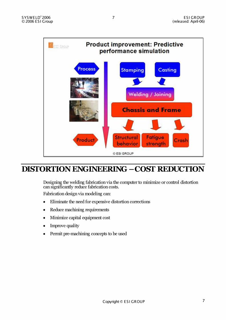
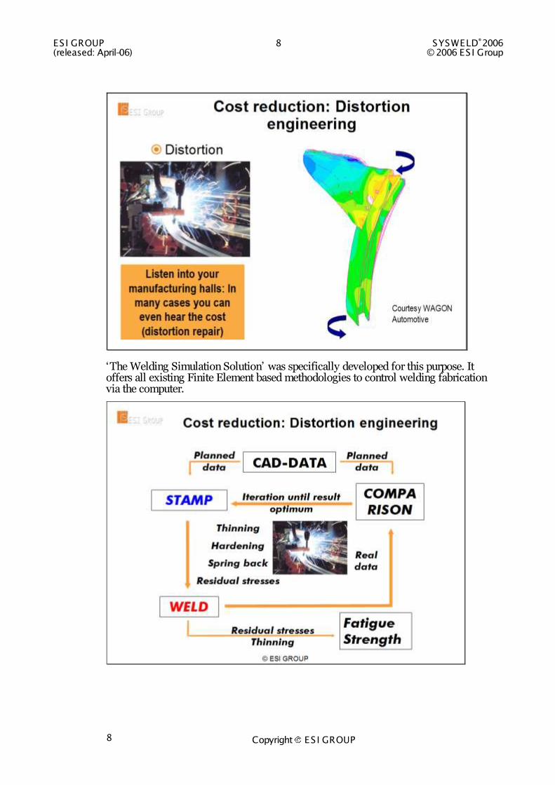
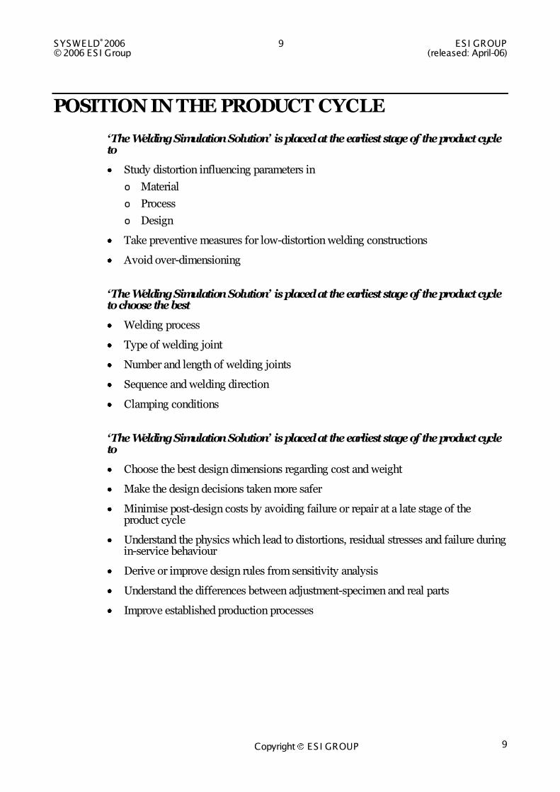
DISTORTION ENGINEERING – COST REDUCTION
Designing the welding fabrication via the computer to minimize or control distortion can significantly reduce fabrication costs.
Fabrication design via modeling can:
Eliminate the need for expensive distortion corrections
Reduce machining requirements
Minimize capital equipment cost
Improve quality
Permit pre-machining concepts to be used
ESI GROUP 8 SYSWELD®2006 (released: April-06) © 2006 ES I Group
Copyright ES I GROUP 8
„The Welding Simulation Solution‟ was specifically developed for this purpose. It offers all existing Finite Element based methodologies to control welding fabrication via the computer.
SYSWELD®2006 9 ES I GROUP © 2006 ES I Group (released: April-06)
Copyright ES I GROUP 9
POSITION IN THE PRODUCT CYCLE
‘The Welding Simulation Solution’ is placed at the earliest stage of the product cycle to
Study distortion influencing parameters in
o Material
o Process
o Design
Take preventive measures for low-distortion welding constructions
Avoid over-dimensioning
‘The Welding Simulation Solution’ is placed at the earliest stage of the product cycle to choose the best
Welding process
Type of welding joint
Number and length of welding joints
Sequence and welding direction
Clamping conditions
‘The Welding Simulation Solution’ is placed at the earliest stage of the product cycle to
Choose the best design dimensions regarding cost and weight
Make the design decisions taken more safer
Minimise post-design costs by avoiding failure or repair at a late stage of the product cycle
Understand the physics which lead to distortions, residual stresses and failure during in-service behaviour
Derive or improve design rules from sensitivity analysis
Understand the differences between adjustment-specimen and real parts
Improve established production processes
ESI GROUP 10 SYSWELD®2006 (released: April-06) © 2006 ES I Group
Copyright ES I GROUP 10
BENEFICIARIES
The beneficiaries are
Producers of Welded mass production parts
o High volume of Welding joints /day
o Anybody using Welding robots
Producers of mission critical parts (space mission equipment, power plants)
Producers of expensive parts (turbines, power plants)
In Terms of Industry sectors
Vehicle and Aerospace Industry
Heavy Industry
Nuclear Industry
Chemical Industry
Suppliers
Universities and Research Institutes
These include:
Product manufacturing
Product design
Durability evaluation
Crash worthiness
Structural behavior - protection of functionality
SYSWELD®2006 11 ES I GROUP © 2006 ES I Group (released: April-06)
Copyright ES I GROUP 11
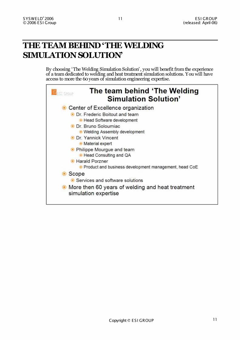
THE TEAM BEHIND ‘THE WELDING SIMULATION SOLUTION’
By choosing „The Welding Simulation Solution‟ , you will benefit from the experience of a team dedicated to welding and heat treatment simulation solutions. You will have access to more the 60 years of simulation engineering expertise.

ESI GROUP 12 SYSWELD®2006 (released: April-06) © 2006 ES I Group
Copyright ES I GROUP 12
REPRESENTATIVE REFERENCES
INDUSTRY
Air Liquide, ALCOA, AW Engineering, Bechtel Bettis, BIAS, BOSCH, CEA Saclay. CEA Valduc, Centro Sviluppo Materiali, CETIM, CNRC-NRC, Corus Technology BV, DaimlerChrysler AG, DENKI KOGYO, ELECTRIC BOAT, FHG IWM, FHG IWS, FRAMATOME, GKN, HITACHI, KENKI HYUNDAI, INA, India Ghandi Center for Atomic Research, JFE SYSTEMS, KAIST, KATECH, Knolls Atomic Power Laboratory, NISSAN, POSCO, Pratt & Whitney Aircraft, PSA, RENAULT, Rolls Royce, SAMSUNG, SERCO, SETVAL, SHANGHAI BOASTEEL, SOLLAC, SUZUKI, TOSHIBA, TOYOTA, UAM, VW, VZLU, ZF
UNIVERSITY AND INSTITUTES
Many Universities and Institutes around the World are using the Welding Simulation Solution of ESI for scientific purposes
GENERAL ESI GROUP
SYSWELD®2006 13 ES I GROUP © 2006 ES I Group (released: April-06)
Copyright ES I GROUP 13
APPLICATIONS
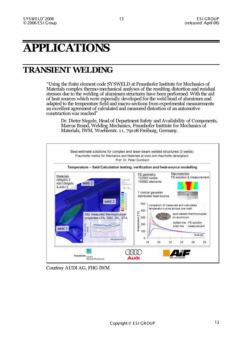
TRANSIENT WELDING
“Using the finite element code SYSWELD at Fraunhofer Institute for Mechanics of Materials complex thermo-mechanical analyses of the resulting distortion and residual stresses due to the welding of aluminum structures have been performed. With the aid of heat sources which were especially developed for the weld bead of aluminum and adapted to the temperature field and macro-sections from experimental measurements an excellent agreement of calculated and measured distortion of an automotive construction was reached”
Dr. Dieter Siegele, Head of Department Safety and Availability of Components, Marcus Brand, Welding Mechanics, Fraunhofer Institute for Mechanics of Materials, IWM, Woehlerstr. 11, 79108 Freiburg, Germany.
Courtesy AUDI AG, FHG IWM

ESI GROUP 14 SYSWELD®2006 (released: April-06) © 2006 ES I Group
Copyright ES I GROUP 14
Courtesy AUDI AG, FHG IWM
Courtesy VW AG
SYSWELD®2006 15 ES I GROUP © 2006 ES I Group (released: April-06)
Copyright ES I GROUP 15
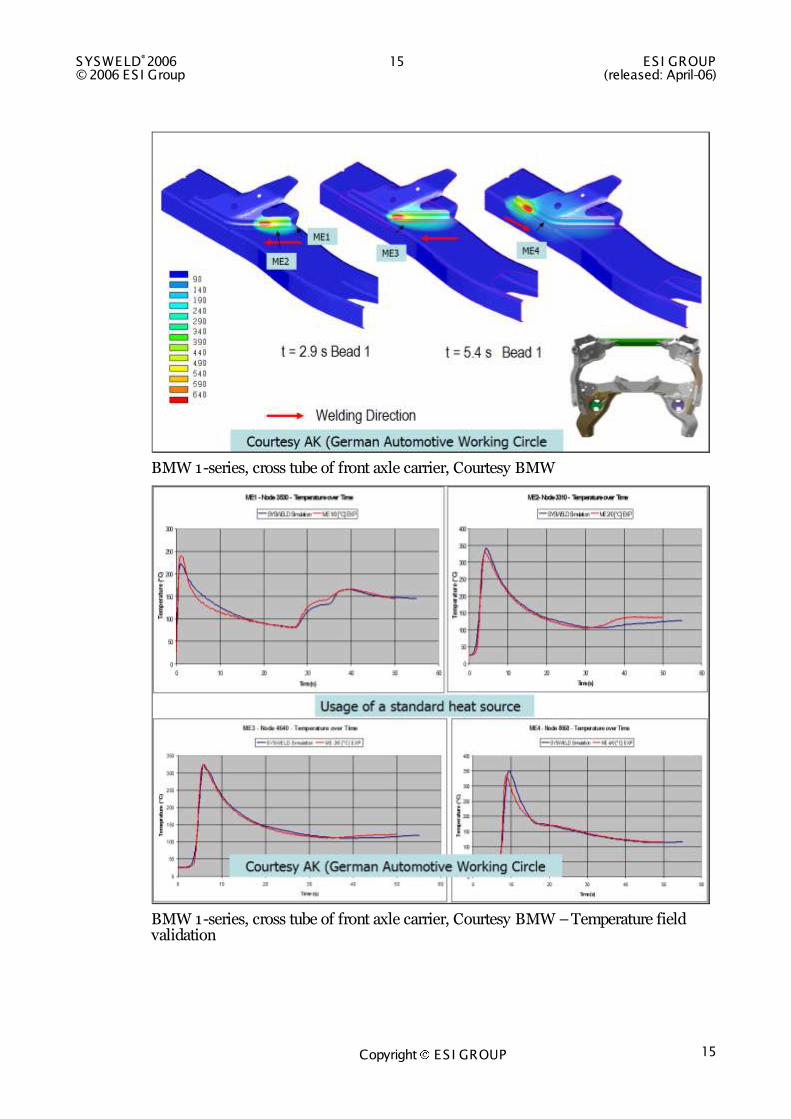
BMW 1-series, cross tube of front axle carrier, Courtesy BMW
BMW 1-series, cross tube of front axle carrier, Courtesy BMW – Temperature field validation
ESI GROUP 16 SYSWELD®2006 (released: April-06) © 2006 ES I Group
Copyright ES I GROUP 16
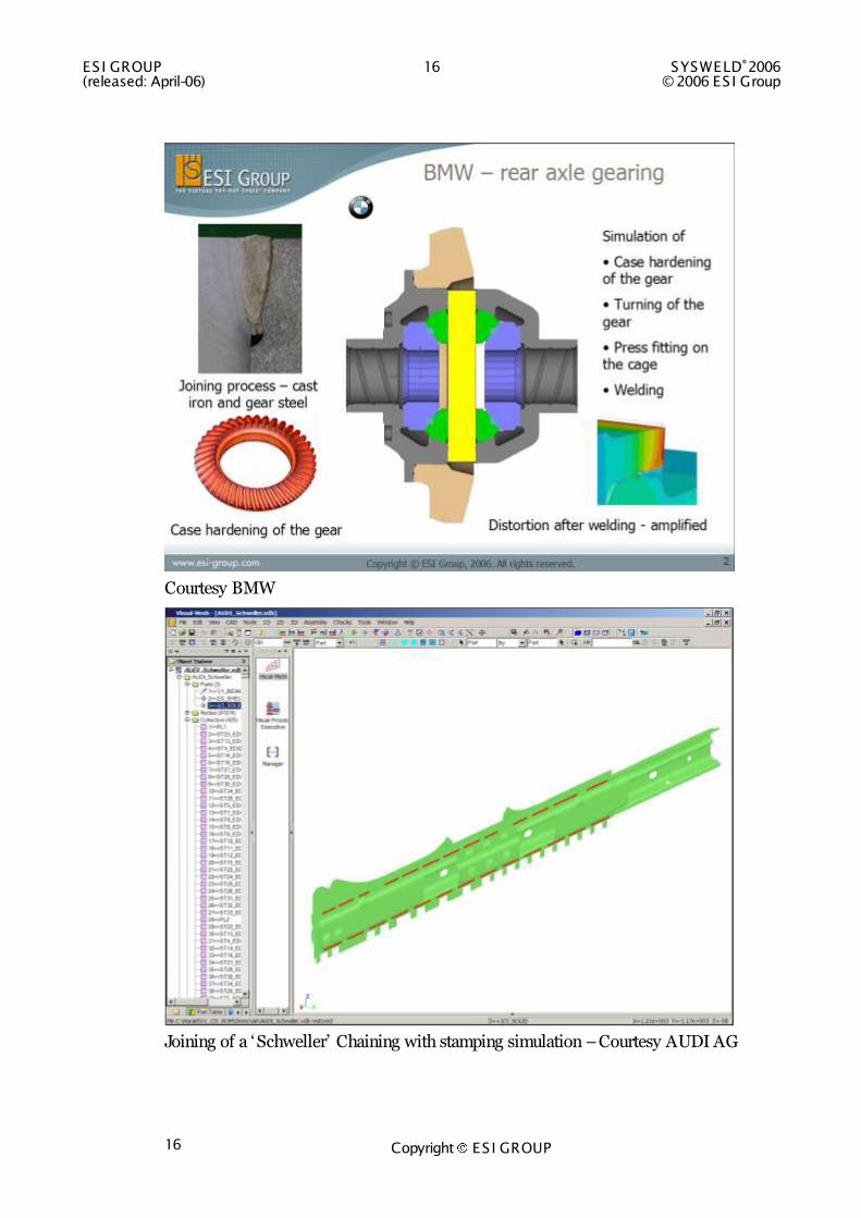
Courtesy BMW
Joining of a „Schweller‟ Chaining with stamping simulation – Courtesy AUDI AG

SYSWELD®2006 17 ES I GROUP © 2006 ES I Group (released: April-06)
Copyright ES I GROUP 17
Welding of a rear axle wing – Courtesy BMW AG
Transient Welding of a door component – Courtesy WAGON Automotive GmbH
ESI GROUP 18 SYSWELD®2006 (released: April-06) © 2006 ES I Group
Copyright ES I GROUP 18
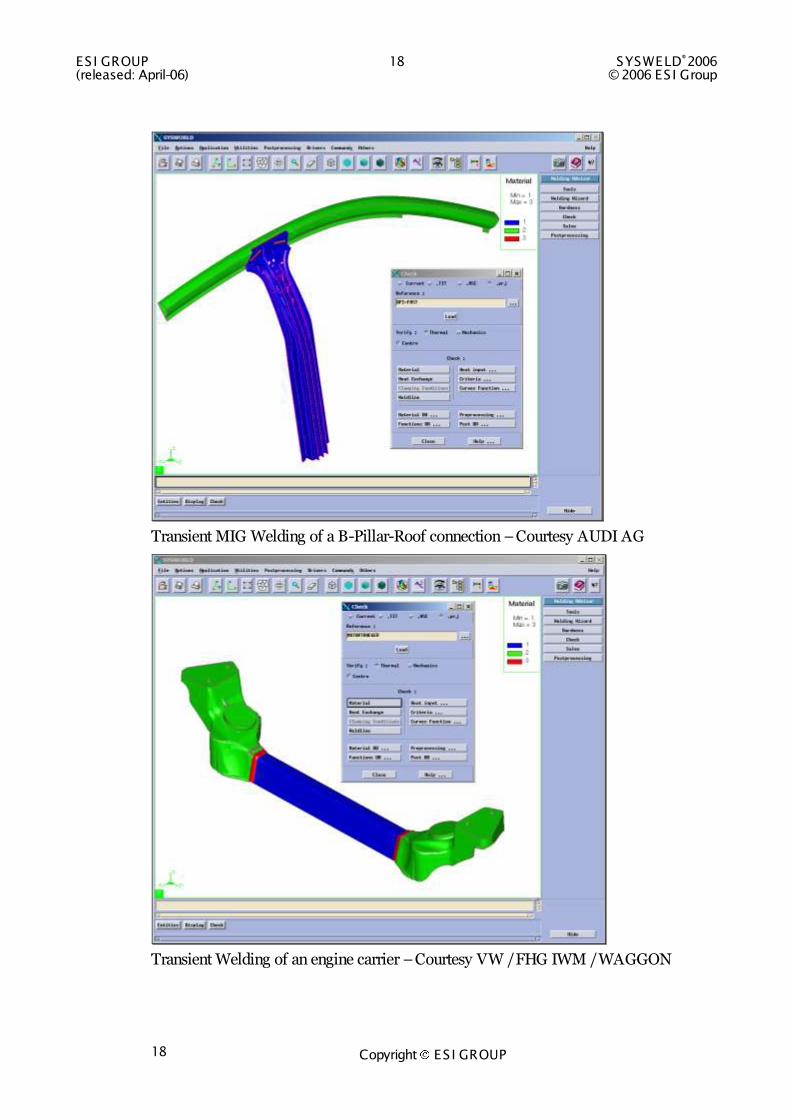
Transient MIG Welding of a B-Pillar-Roof connection – Courtesy AUDI AG
Transient Welding of an engine carrier – Courtesy VW / FHG IWM / WAGGON
SYSWELD®2006 19 ES I GROUP © 2006 ES I Group (released: April-06)
Copyright ES I GROUP 19
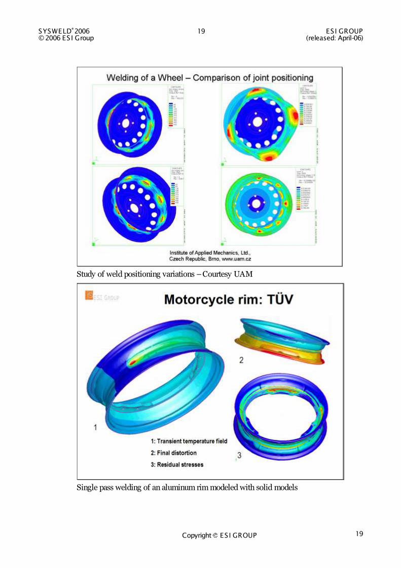
Study of weld positioning variations – Courtesy UAM
Single pass welding of an aluminum rim modeled with solid models
ESI GROUP 20 SYSWELD®2006 (released: April-06) © 2006 ES I Group
Copyright ES I GROUP 20
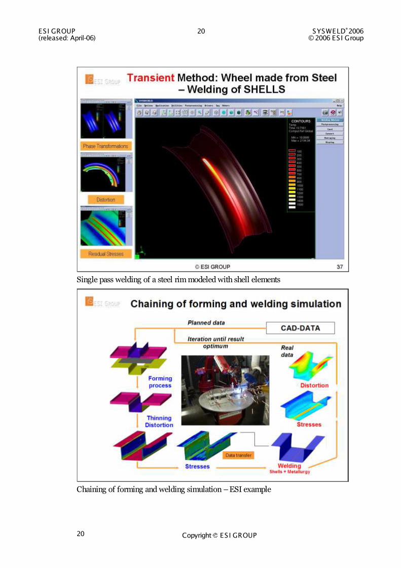
Single pass welding of a steel rim modeled with shell elements
Chaining of forming and welding simulation – ESI example

SYSWELD®2006 21 ES I GROUP © 2006 ES I Group (released: April-06)
Copyright ES I GROUP 21
Chaining welding and stamping simulation – extraction ESI Brochure
Joining of stamping and welding simulation – Courtesy IWB
ESI GROUP 22 SYSWELD®2006 (released: April-06) © 2006 ES I Group
Copyright ES I GROUP 22
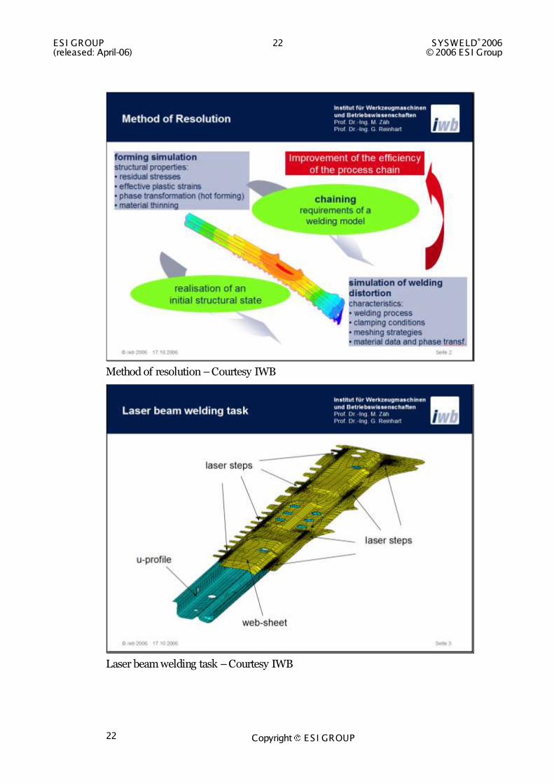
Method of resolution – Courtesy IWB
Laser beam welding task – Courtesy IWB

SYSWELD®2006 23 ES I GROUP © 2006 ES I Group (released: April-06)
Copyright ES I GROUP 23
Final distortion – Courtesy IWB
Measurements – solid model, shell mode without chaining, shell mode with chaining – Courtesy IWB
ESI GROUP 24 SYSWELD®2006 (released: April-06) © 2006 ES I Group
Copyright ES I GROUP 24
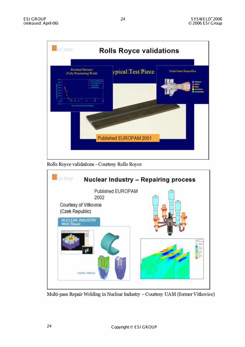
Rolls Royce validations - Courtesy Rolls Royce
Multi-pass Repair Welding in Nuclear Industry – Courtesy UAM (former Vitkovice)
SYSWELD®2006 25 ES I GROUP © 2006 ES I Group (released: April-06)
Copyright ES I GROUP 25
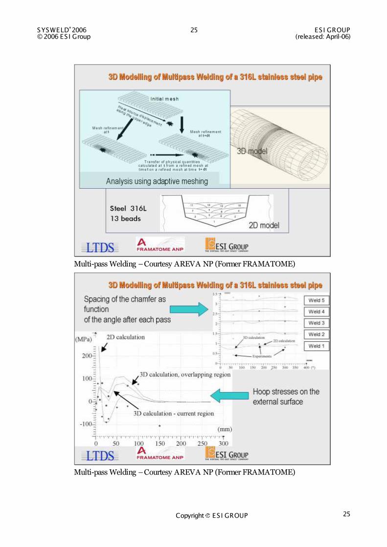
Multi-pass Welding – Courtesy AREVA NP (Former FRAMATOME)
Multi-pass Welding – Courtesy AREVA NP (Former FRAMATOME)
ESI GROUP 26 SYSWELD®2006 (released: April-06) © 2006 ES I Group
Copyright ES I GROUP 26
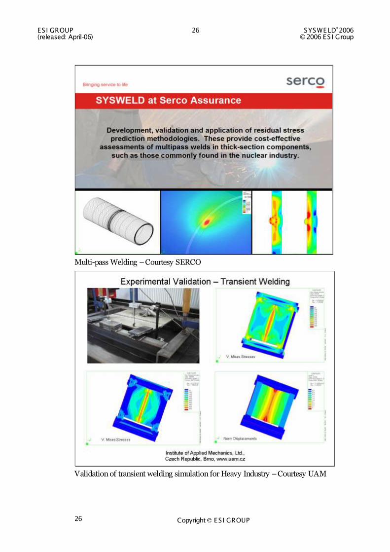
Multi-pass Welding – Courtesy SERCO
Validation of transient welding simulation for Heavy Industry – Courtesy UAM
SYSWELD®2006 27 ES I GROUP © 2006 ES I Group (released: April-06)
Copyright ES I GROUP 27
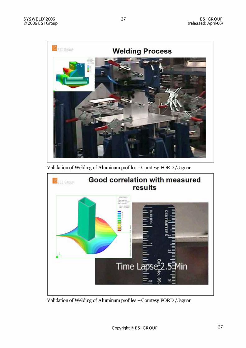
Validation of Welding of Aluminum profiles – Courtesy FORD / Jaguar
Validation of Welding of Aluminum profiles – Courtesy FORD / Jaguar

ESI GROUP 28 SYSWELD®2006 (released: April-06) © 2006 ES I Group
Copyright ES I GROUP 28
STEADY STATE WELDING
Courtesy Aerospatiale
Steady state welding – ESI example
SYSWELD®2006 29 ES I GROUP © 2006 ES I Group (released: April-06)
Copyright ES I GROUP 29
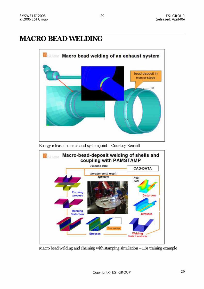
MACRO BEAD WELDING
Energy release in an exhaust system joint – Courtesy Renault
Macro bead welding and chaining with stamping simulation – ESI training example

ESI GROUP 30 SYSWELD®2006 (released: April-06) © 2006 ES I Group
Copyright ES I GROUP 30
Typical Heavy Industry Specimen – ESI training example

SYSWELD®2006 31 ES I GROUP © 2006 ES I Group (released: April-06)
Copyright ES I GROUP 31
WELDING ASSEMBLY “A very good agreement has been achieved between measurements and simulations”
Marek Slovacek, Ph.D, Head of the department Technology processes, Institute of the applied mechanics Brno, Ltd., Veveri 95, 611 00 Brno, Czech republic, about the Local-Global Approach
Validation of the local-global method for Heavy Industry – Courtesy UAM
The local-global method in Heavy Industry – Courtesy UAM and ANSALDO

ESI GROUP 32 SYSWELD®2006 (released: April-06) © 2006 ES I Group
Copyright ES I GROUP 32
Welding of a front axle carrier – Courtesy BMW AG
Welding Assembly of a chassis component – Courtesy Renault
SYSWELD®2006 33 ES I GROUP © 2006 ES I Group (released: April-06)
Copyright ES I GROUP 33
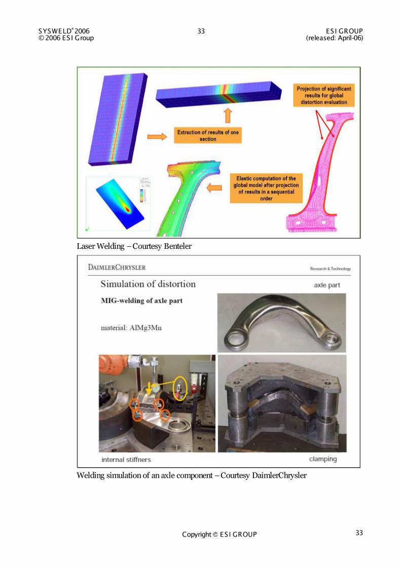
Laser Welding – Courtesy Benteler
Welding simulation of an axle component – Courtesy DaimlerChrysler
ESI GROUP 34 SYSWELD®2006 (released: April-06) © 2006 ES I Group
Copyright ES I GROUP 34
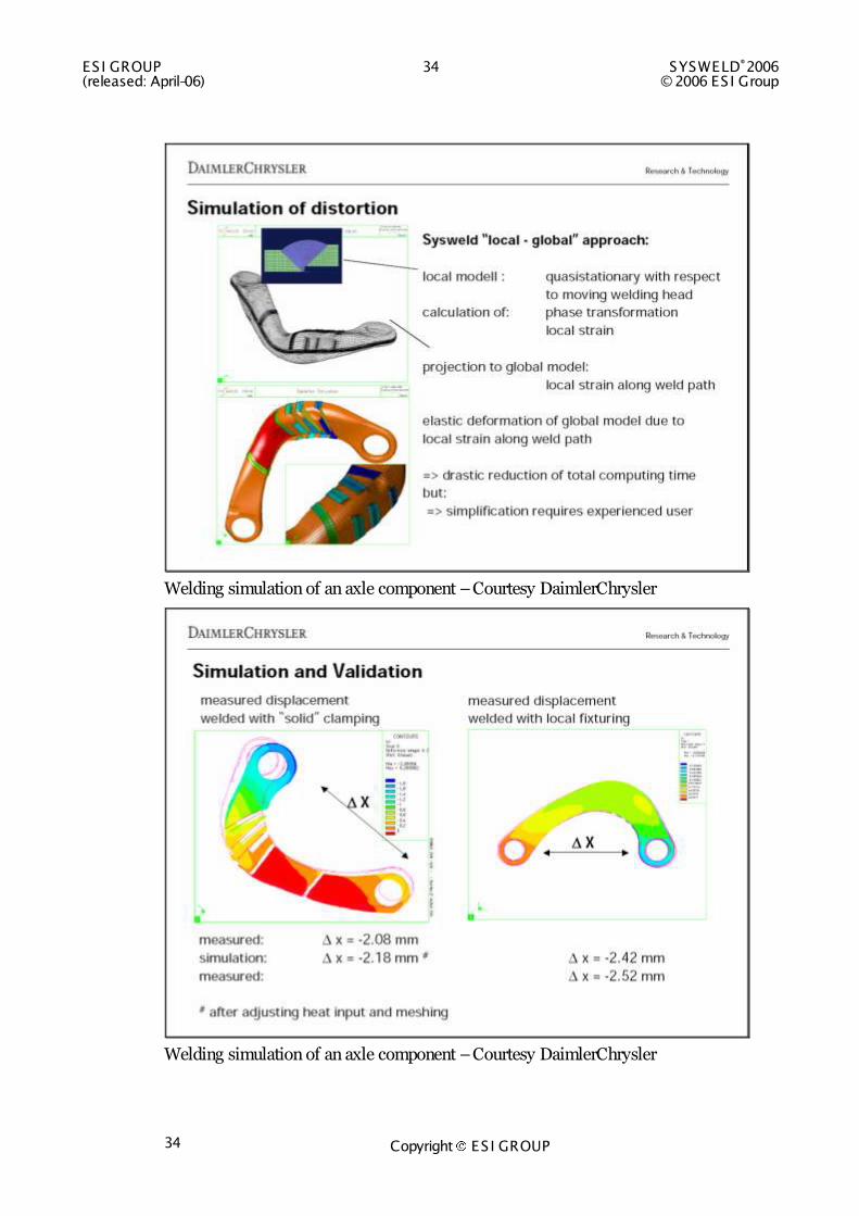
Welding simulation of an axle component – Courtesy DaimlerChrysler
Welding simulation of an axle component – Courtesy DaimlerChrysler

SYSWELD®2006 35 ES I GROUP © 2006 ES I Group (released: April-06)
Copyright ES I GROUP 35
Welding Assembly of a bumper – Courtesy GM
Welding Assembly and comparison with measurements – Courtesy Alcoa
ESI GROUP 36 SYSWELD®2006 (released: April-06) © 2006 ES I Group
Copyright ES I GROUP 36
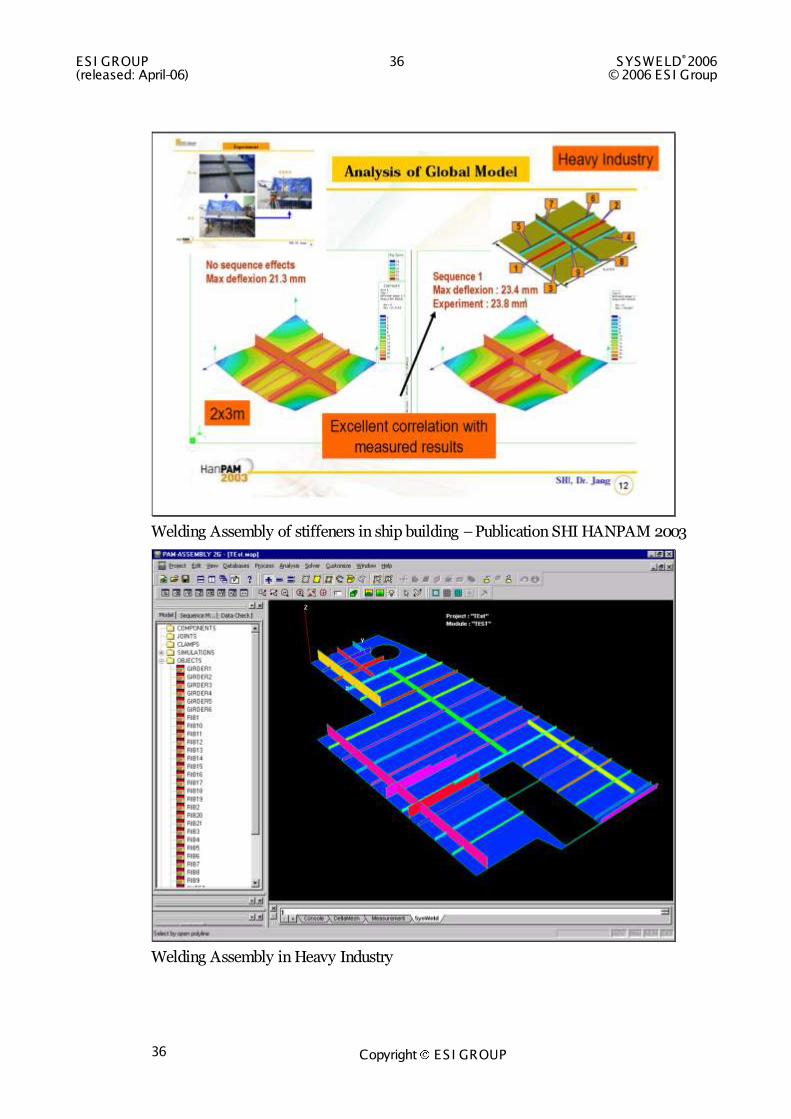
Welding Assembly of stiffeners in ship building – Publication SHI HANPAM 2003
Welding Assembly in Heavy Industry
SYSWELD®2006 37 ES I GROUP © 2006 ES I Group (released: April-06)
Copyright ES I GROUP 37
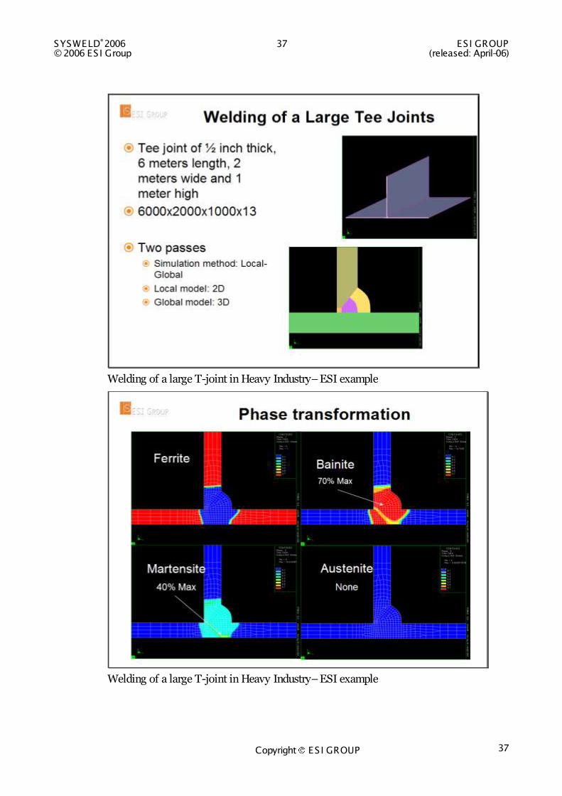
Welding of a large T-joint in Heavy Industry– ESI example
Welding of a large T-joint in Heavy Industry– ESI example
ESI GROUP 38 SYSWELD®2006 (released: April-06) © 2006 ES I Group
Copyright ES I GROUP 38
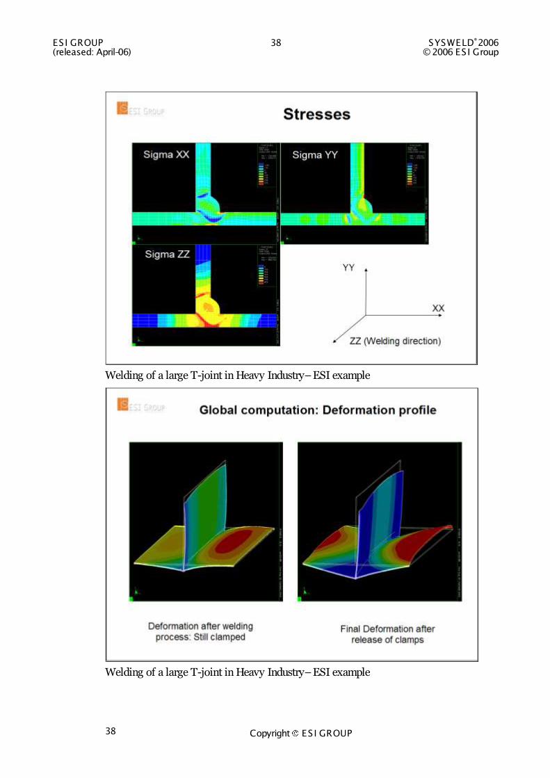
Welding of a large T-joint in Heavy Industry– ESI example
Welding of a large T-joint in Heavy Industry– ESI example
SYSWELD®2006 39 ES I GROUP © 2006 ES I Group (released: April-06)
Copyright ES I GROUP 39
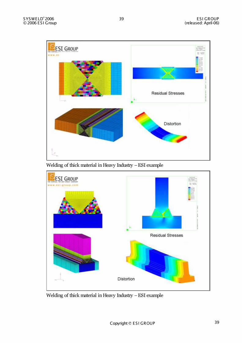
Welding of thick material in Heavy Industry – ESI example
Welding of thick material in Heavy Industry – ESI example
ESI GROUP 40 SYSWELD®2006 (released: April-06) © 2006 ES I Group
Copyright ES I GROUP 40
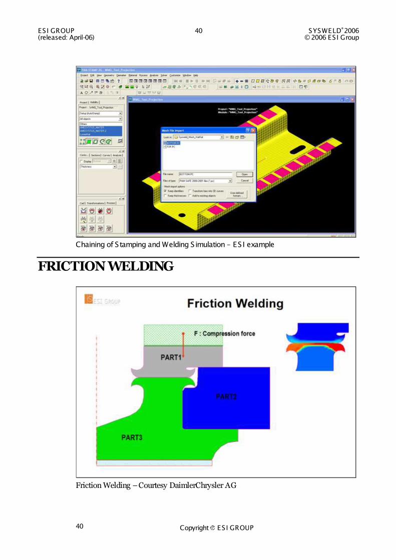
Chaining of Stamping and Welding S imulation – ES I example
FRICTION WELDING
Friction Welding – Courtesy DaimlerChrysler AG
SYSWELD®2006 41 ES I GROUP © 2006 ES I Group (released: April-06)
Copyright ES I GROUP 41
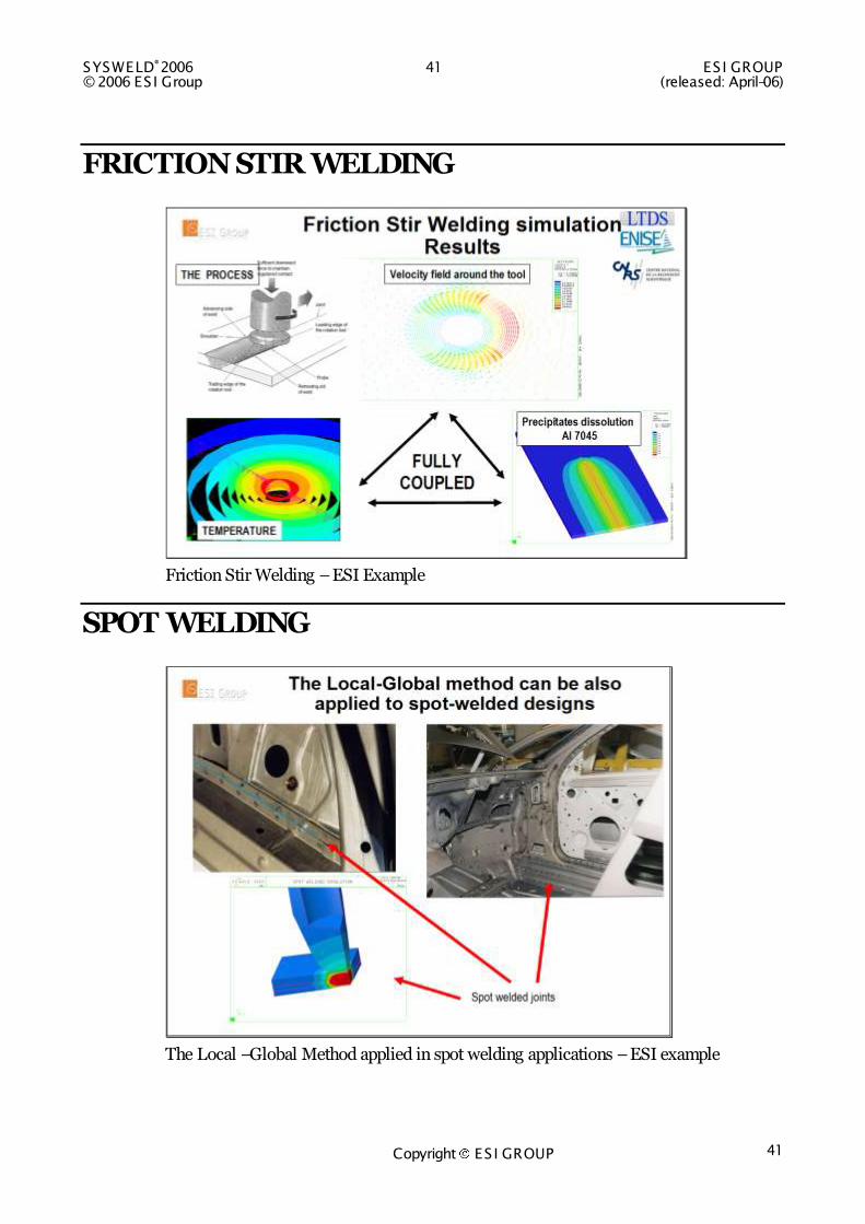
FRICTION STIR WELDING
Friction Stir Welding – ESI Example
SPOT WELDING
The Local –Global Method applied in spot welding applications – ESI example
ESI GROUP 42 SYSWELD®2006 (released: April-06) © 2006 ES I Group
Copyright ES I GROUP 42
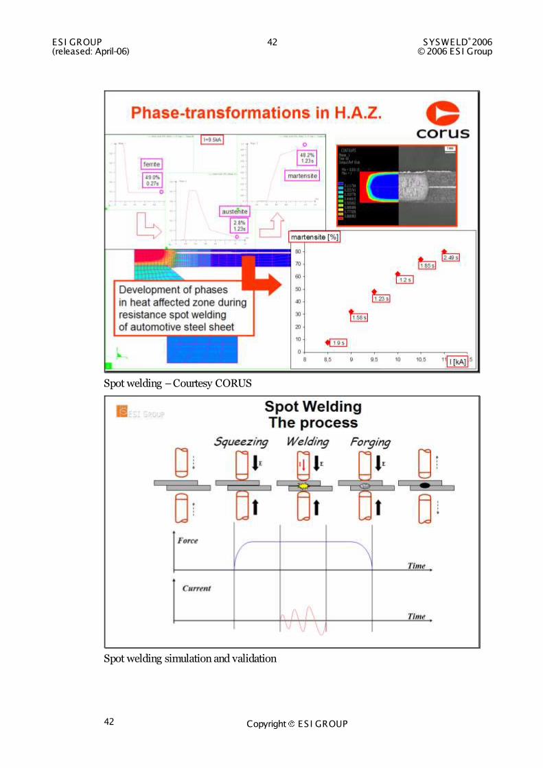
Spot welding – Courtesy CORUS
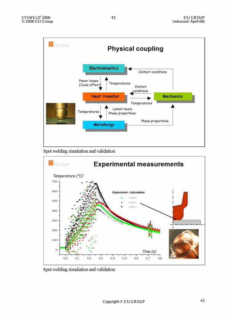
Spot welding simulation and validation
SYSWELD®2006 43 ES I GROUP © 2006 ES I Group (released: April-06)
Copyright ES I GROUP 43
Spot welding simulation and validation
Spot welding simulation and validation

ESI GROUP 44 SYSWELD®2006 (released: April-06) © 2006 ES I Group
Copyright ES I GROUP 44
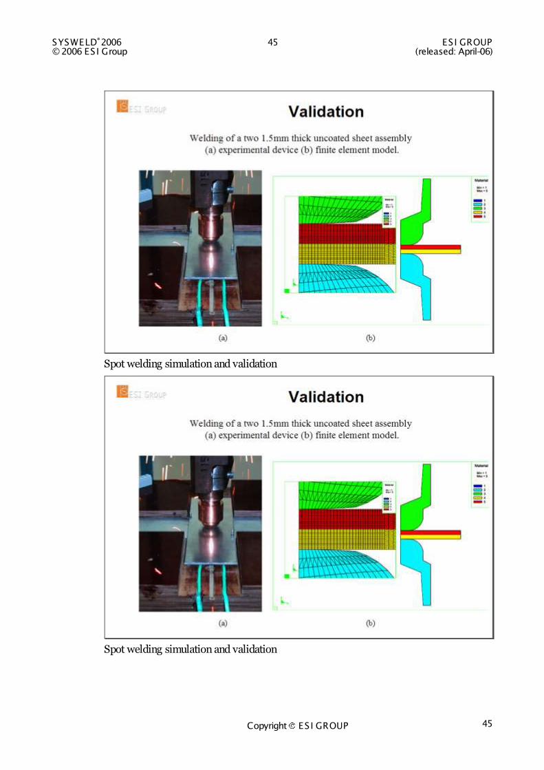
Spot welding simulation and validation
Spot welding simulation and validation
SYSWELD®2006 45 ES I GROUP © 2006 ES I Group (released: April-06)
Copyright ES I GROUP 45
Spot welding simulation and validation
Spot welding simulation and validation

ESI GROUP 46 SYSWELD®2006 (released: April-06) © 2006 ES I Group
Copyright ES I GROUP 46
Spot welding simulation and validation
Spot welding simulation and validation
SYSWELD®2006 47 ES I GROUP © 2006 ES I Group (released: April-06)
Copyright ES I GROUP 47
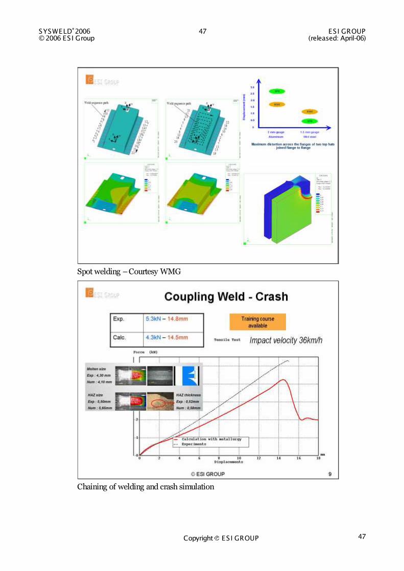
Spot welding – Courtesy WMG
Chaining of welding and crash simulation
ESI GROUP 48 SYSWELD®2006 (released: April-06) © 2006 ES I Group
Copyright ES I GROUP 48
SCIENTIFIC WORK
WHAT DO THE EXPERTS SAY
“Using the finite element code SYSWELD at Fraunhofer Institute for Mechanics of Materials complex thermo-mechanical analyses of the resulting distortion and residual stresses due to the welding of aluminum structures have been performed. With the aid of heat sources which were especially developed for the weld bead of aluminum and adapted to the temperature field and macro-sections from experimental measurements an excellent agreement of calculated and measured distortion of an automotive construction was reached”
Dr. Dieter Siegele, Head of Department Safety and Availability of Components, Marcus Brand, Welding Mechanics, Fraunhofer Institute for Mechanics of Materials, IWM, Woehlerstr. 11, 79108 Freiburg, Germany.
“A very good agreement has been achieved between measurements and simulations”
Marek Slovacek, Ph.D, Head of the department Technology processes, Institute of the applied mechanics Brno, Ltd., Veveri 95, 611 00 Brno, Czech republic, about the Local-Global Approach
"SYSWELD has not only accompanied our scientific research, concerning the fundamental principals of welding distortion and residual stresses of structures, but also opened the way for considering complex 3-d components. Using either transient computation methods or reduced models helped to achieve excellent results concerning the structural behaviour of welded parts."
Dipl.-Ing. Loucas Papadakis, Fügetechnologien, Institut für Werkzeugmaschinen, und Betriebswissenschaften (iwb), TU München, Boltzmannstr. 15, 85748 Garching
"At the Institute for Machine Tools and Industrial Management iwb (Technische Universität München), SYSWELD is intensively used for more then 5 years. It is applied as a strong tool for detecting part specific properties, e.g. stresses and distortion, during and immediately after treating by welding in an early state of Product Life Cycle. We look upon this program favorable in the production of tomorrow due to the still unexploited possibilities of this program."
Dipl.-Ing. Sven Roeren, Fügetechnologien, Institut für Werkzeugmaschinen, und Betriebswissenschaften (iwb), TU München, Boltzmannstr. 15, 85748 Garching
“The Bremer Institut für angewandte Strahltechnik (BIAS) uses SYSWELD for the simulation of various welding processes and the calculation of welding distortions. One essential advantage of SYSWELD is the consideration of phase transformations which are important for residual stress calculation in laser heat treatment. SYSWELD has been approved itself as a very useful tool to estimate process parameters ahead of experiments whereby time and costs could be reduced.”

SYSWELD®2006 49 ES I GROUP © 2006 ES I Group (released: April-06)
Copyright ES I GROUP 49
Dipl.-Ing. Jörg Woitschig, BIAS, Bremer Institut für angewandte Strahltechnik, Abt. Werkstoffe und Modellierung
“In the very complex field of welding and heat treatments simulation, new methodologies are necessary in order to follow the severe industry demand of reliability and low time cost. Sysweld is a numerical code that with its own routines and implemented metallurgical laws taken from International literature, fully satisfy these requirements. A great work we have done to verify the reliability of welding simulation with Sysweld by comparing numerical and experimental results in terms of temperature history and residual stresses; very good agreements were found. Another key factor is the excellent technical and numerical support we have always found by the ESI-Group members.”
P. Ferro, F. Bonollo, A. Tiziani, DTG - University of Padova, Stradella S. Nicola 3 36100 Vicenza (Italy)
“The Finite-Element-Program Sysweld has a logically founded and well elaborated structure of program and organization of data. The language of input-files is easily understandable. The possibility of calculating of phase transformation, the possibility of defining moving heat sources by weld lines in a simple way, the possibility of defining arbitrary functions in the data input, the possibility of using different solution procedures, and many other helpful features making Sysweld an excellent tool for research, which is not only used for welding simulation.”
Dipl.-Ing. Tobias Loose, European Welding Engineer, Lehrstuhl für Stahlbau, Universität Karlsruhe (TH), Kaiserstraße 12, D-76131 Karlsruhe
“In our Institute of Manufacturing and Welding Technology we use the Finite-Element-Code SYSWELD for the modeling of welding residual stresses both in public and in industrial R&D projects. The SYSWELD Code has a good functionality and a high scientific level. The ESI working group is ever striving to inform the users how to do a good welding modeling, and it distributes regularly useful information among the users. The ESI presentations are an excellent tool in our Institute's lectures on Welding Simulation.”
Dr.rer.nat. U.Semmler, Chemnitz University of Technology, Institute of Manufacturing and Welding Technology Reichenhainer Str. 70, D-09126 Chemnitz
“The welding simulation is a large domain that covers from trivial to complex problems, where various phenomena take part and require interpretation. This fact is valid in the both fields – research and industry. In that context a proper simulation code should supply possibilities for free definition of physical and phenomenological models; possibilities for their coupling into complex analyses; abilities for creating routines as well as a suitable tool for presentation of the results. Definitively, SYSWELD successfully attain these requirements.”
N. Doynov, Dr.-Ing., Chair of Joining Technology, Technical University of Brandenburg, Cottbus, Germany
ESI GROUP 50 SYSWELD®2006 (released: April-06) © 2006 ES I Group
Copyright ES I GROUP 50
“The commercial FE-software Sysweld provides the means to model and analyze complexly transformations of structure for metallic materials, and steel in particular. Therefore, it is now possible to investigate welding and heat treatment in a realistic manner. We are not aware of any other commercial software, which provides the functionality to realize such investigations with the required complexity. Sysweld is a flexible software which allows for scientific investigations to facilitate research, as well as practical applications, such as the optimization of welding processes or the prediction of complex residual stress behaviors states of residual stresses) in a variety of metallic materials. Sysweld was used in innovative research on welding processes with silica glass and has also shown excellent results. The application and partial improvement of the software forms a vital basis for our ability to do research and for the acceptance of our findings.”
Prof. Dr.-Ing. habil. Frank Werner, Head of Department Steel Structures, Bauhaus-Universität Weimar, Marienstrasse 5, 99423 Weimar, Germany
SYSWELD®2006 51 ES I GROUP © 2006 ES I Group (released: April-06)
Copyright ES I GROUP 51
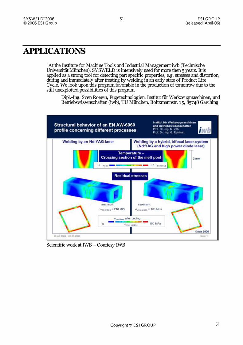
APPLICATIONS
"At the Institute for Machine Tools and Industrial Management iwb (Technische Universität München), SYSWELD is intensively used for more then 5 years. It is applied as a strong tool for detecting part specific properties, e.g. stresses and distortion, during and immediately after treating by welding in an early state of Product Life Cycle. We look upon this program favorable in the production of tomorrow due to the still unexploited possibilities of this program."
Dipl.-Ing. Sven Roeren, Fügetechnologien, Institut für Werkzeugmaschinen, und Betriebswissenschaften (iwb), TU München, Boltzmannstr. 15, 85748 Garching
Scientific work at IWB – Courtesy IWB

ESI GROUP 52 SYSWELD®2006 (released: April-06) © 2006 ES I Group
Copyright ES I GROUP 52
SLV Munich
Comparison with measurements – Aluminum welding – Courtesy SLV Munich

SYSWELD®2006 53 ES I GROUP © 2006 ES I Group (released: April-06)
Copyright ES I GROUP 53
Laser Welding – INZAT
Laser Welding - INZAT
ESI GROUP 54 SYSWELD®2006 (released: April-06) © 2006 ES I Group
Copyright ES I GROUP 54
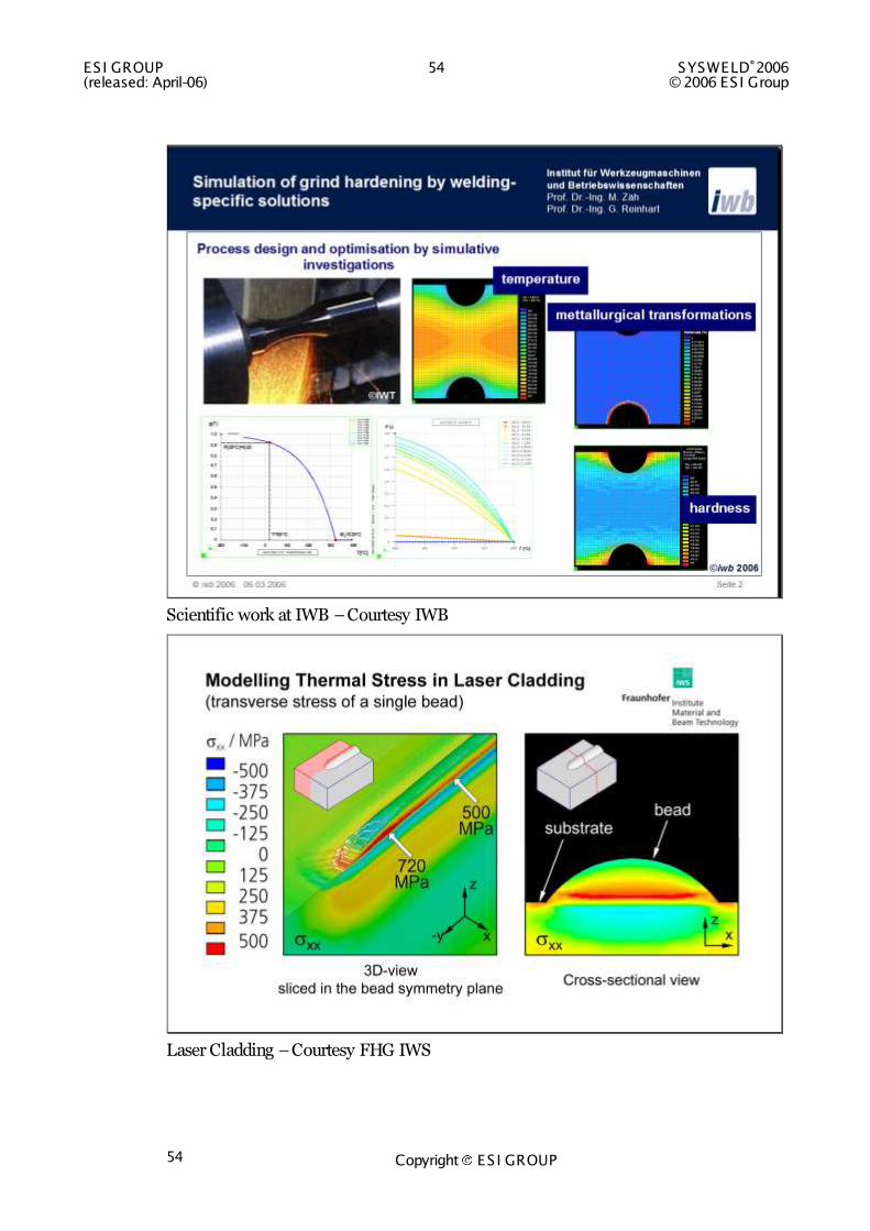
Scientific work at IWB – Courtesy IWB
Laser Cladding – Courtesy FHG IWS
SYSWELD®2006 55 ES I GROUP © 2006 ES I Group (released: April-06)
Copyright ES I GROUP 55
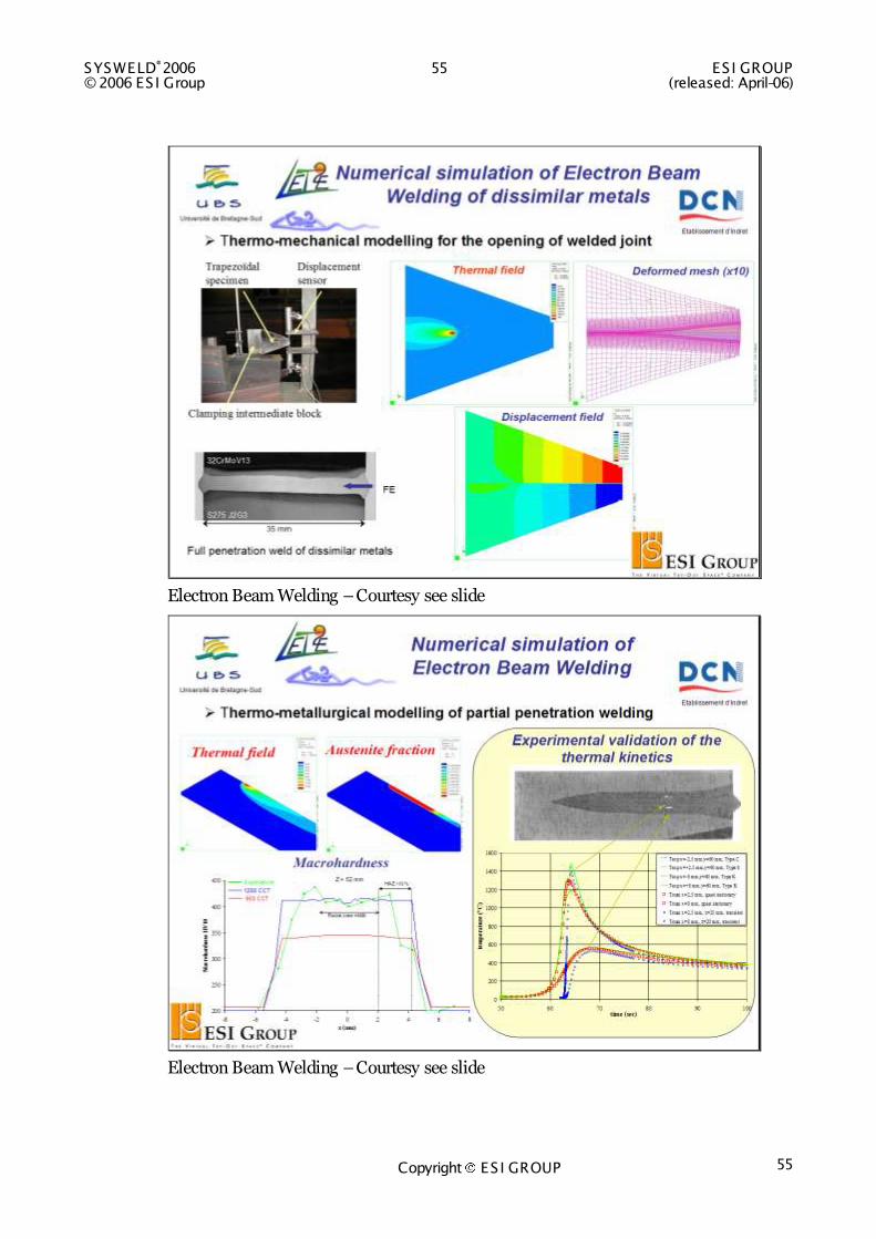
Electron Beam Welding – Courtesy see slide
Electron Beam Welding – Courtesy see slide
ESI GROUP 56 SYSWELD®2006 (released: April-06) © 2006 ES I Group
Copyright ES I GROUP 56
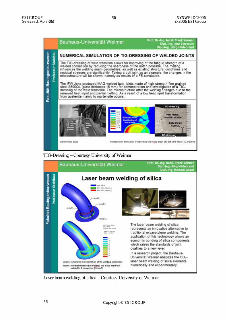
TIG-Dressing – Courtesy University of Weimar
Laser beam welding of silica – Courtesy University of Weimar
SYSWELD®2006 57 ES I GROUP © 2006 ES I Group (released: April-06)
Copyright ES I GROUP 57
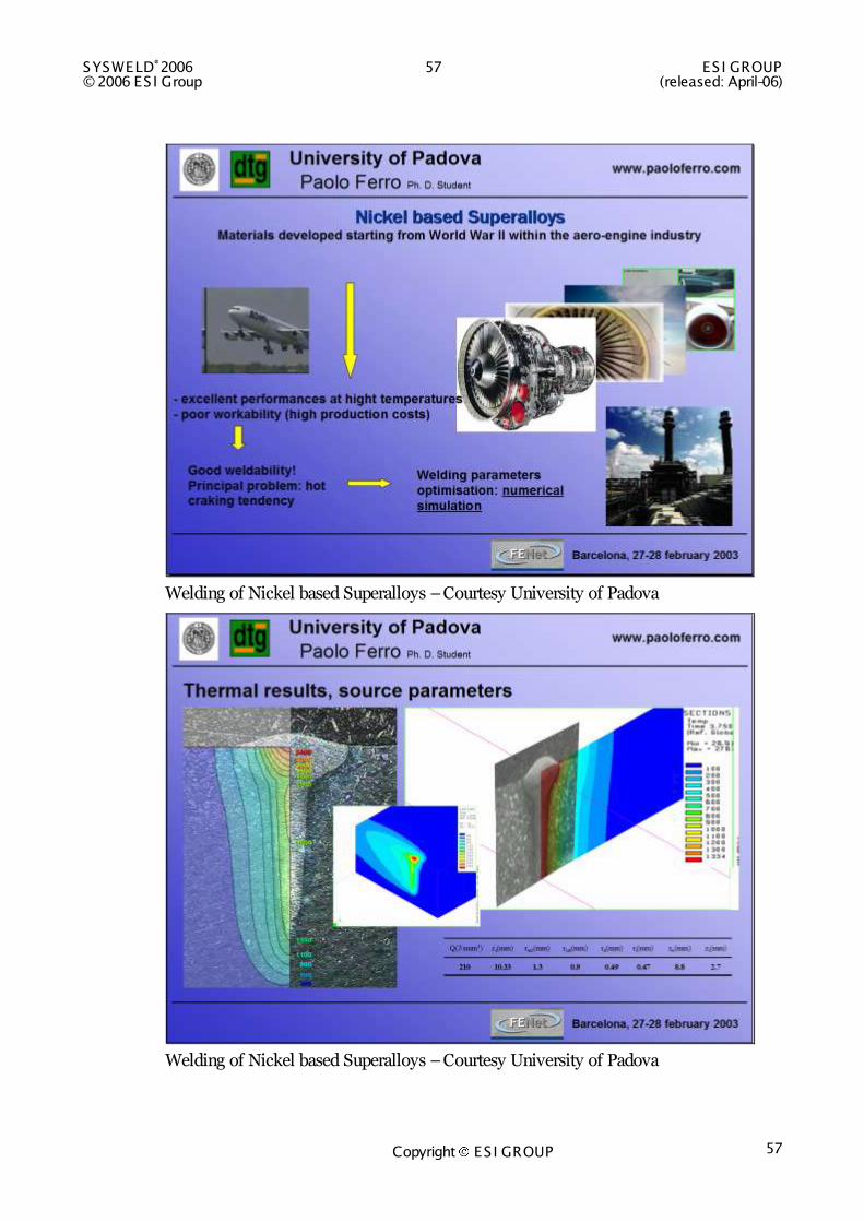
Welding of Nickel based Superalloys – Courtesy University of Padova
Welding of Nickel based Superalloys – Courtesy University of Padova
ESI GROUP 58 SYSWELD®2006 (released: April-06) © 2006 ES I Group
Copyright ES I GROUP 58
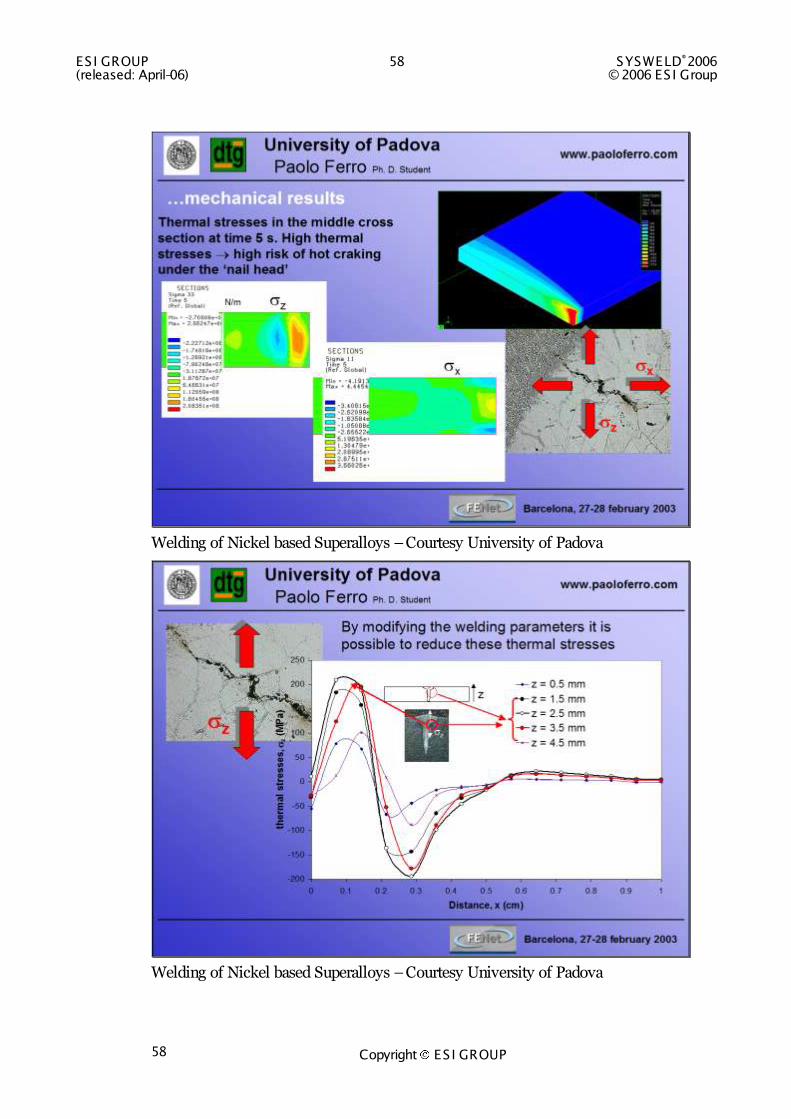
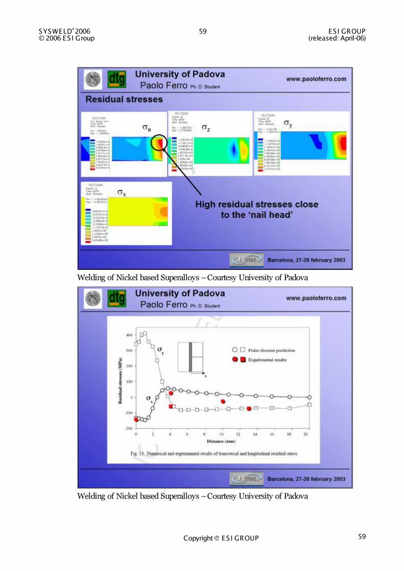
Welding of Nickel based Superalloys – Courtesy University of Padova
Welding of Nickel based Superalloys – Courtesy University of Padova
SYSWELD®2006 59 ES I GROUP © 2006 ES I Group (released: April-06)
Copyright ES I GROUP 59
Welding of Nickel based Superalloys – Courtesy University of Padova
Welding of Nickel based Superalloys – Courtesy University of Padova
ESI GROUP 60 SYSWELD®2006 (released: April-06) © 2006 ES I Group
Copyright ES I GROUP 60
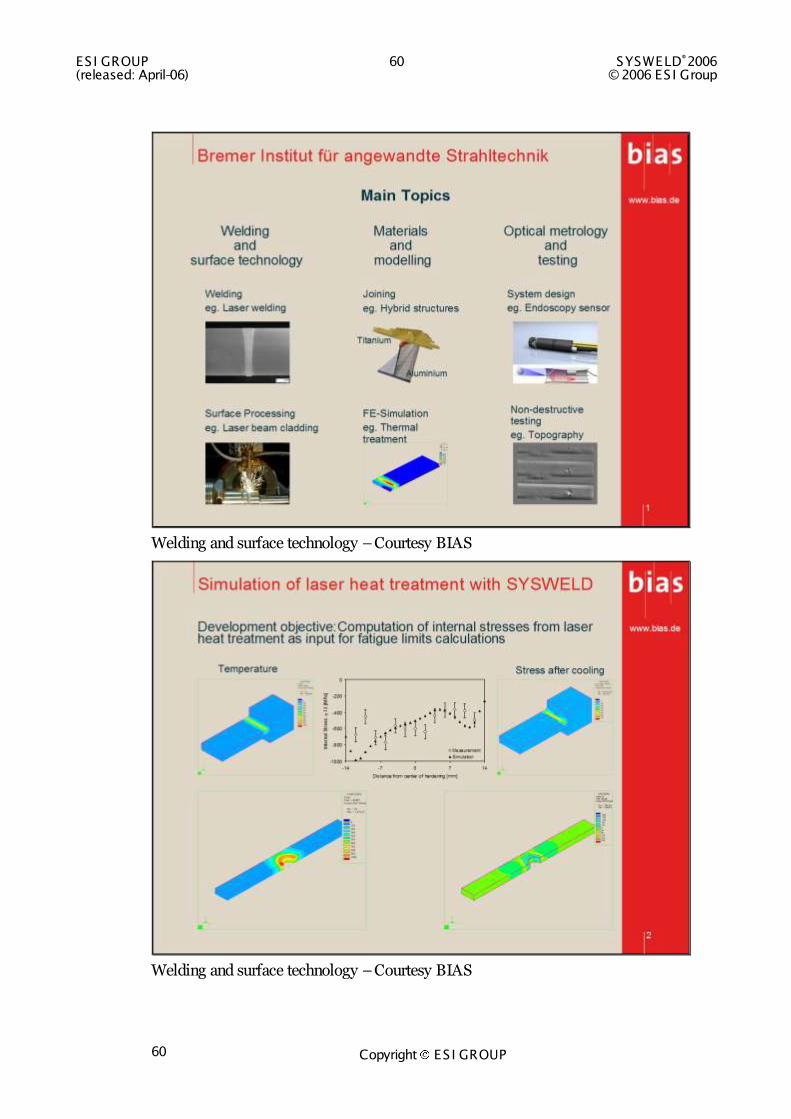
Welding and surface technology – Courtesy BIAS
Welding and surface technology – Courtesy BIAS

SYSWELD®2006 61 ES I GROUP © 2006 ES I Group (released: April-06)
Copyright ES I GROUP 61
Scientific work at BTU Cottbus
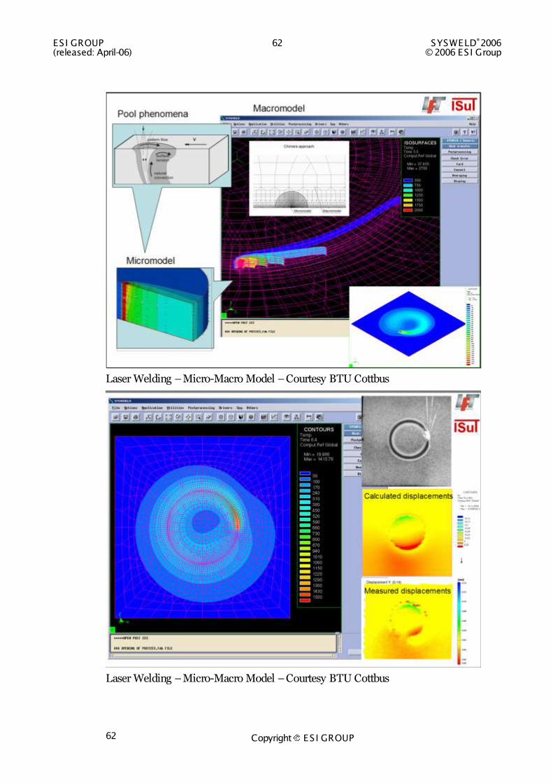
An external process model for weld pool simulation of the laser beam welding has been developed. This model considers all relevant physical phenomena that influence the shape of the weld pool, e.g. convection and Marangoni effect. The process model calculates furthermore the temperature field in a local domain inside and around the weld pool (Micro-model). The temperatures are transferred to the global FE-model (Macro-model) by chimera approach. A procedure in SYSWELD has been created for this purpose.
This procedure allows correction of the temperature field at every time step considering the temporary conditions, obtained from the mechanical response of the body, e.g. the gap opening during welding. It also involves simple parameters for adjusting the weld pool size and shape to experimental data.
Benefits:
o Improved precision of the calculated displacements due to precise description of the temperature field
o Simulation of laser beam welding, regarding the heat input variation after the gap opening
Laser Welding – Micro-Macro Model taking into account changes in the gap and fluid flow – Courtesy BTU Cottbus
ESI GROUP 62 SYSWELD®2006 (released: April-06) © 2006 ES I Group
Copyright ES I GROUP 62
Laser Welding – Micro-Macro Model – Courtesy BTU Cottbus
Laser Welding – Micro-Macro Model – Courtesy BTU Cottbus
SYSWELD®2006 63 ES I GROUP © 2006 ES I Group (released: April-06)
Copyright ES I GROUP 63
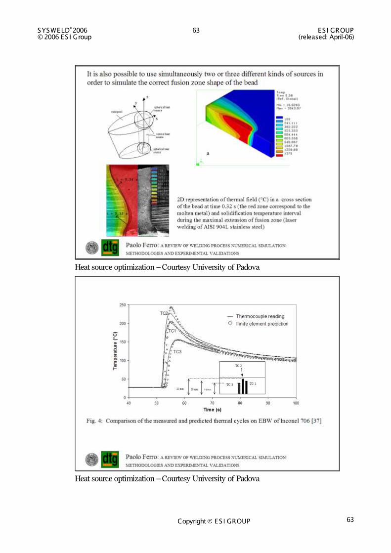
Heat source optimization – Courtesy University of Padova
Heat source optimization – Courtesy University of Padova

ESI GROUP 64 SYSWELD®2006 (released: April-06) © 2006 ES I Group
Copyright ES I GROUP 64
Phase proportions in Multi-Pass Welding – Courtesy University of Padova
Multi-pass welding – Courtesy Institute de Soudure

SYSWELD®2006 65 ES I GROUP © 2006 ES I Group (released: April-06)
Copyright ES I GROUP 65
Welding simulation using advanced meshing techniques – Courtesy CNRS
Welding simulation using advanced meshing techniques – Courtesy CNRS
ESI GROUP 66 SYSWELD®2006 (released: April-06) © 2006 ES I Group
Copyright ES I GROUP 66
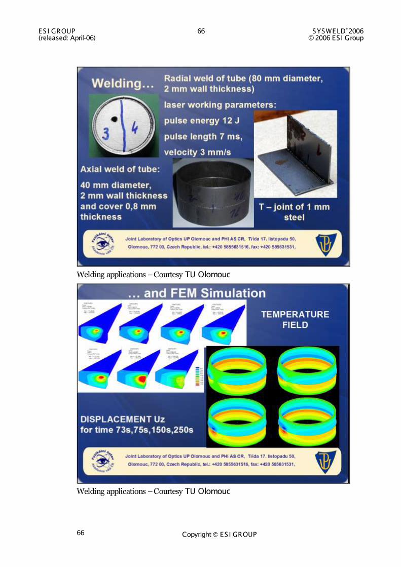
Welding applications – Courtesy TU Olomouc
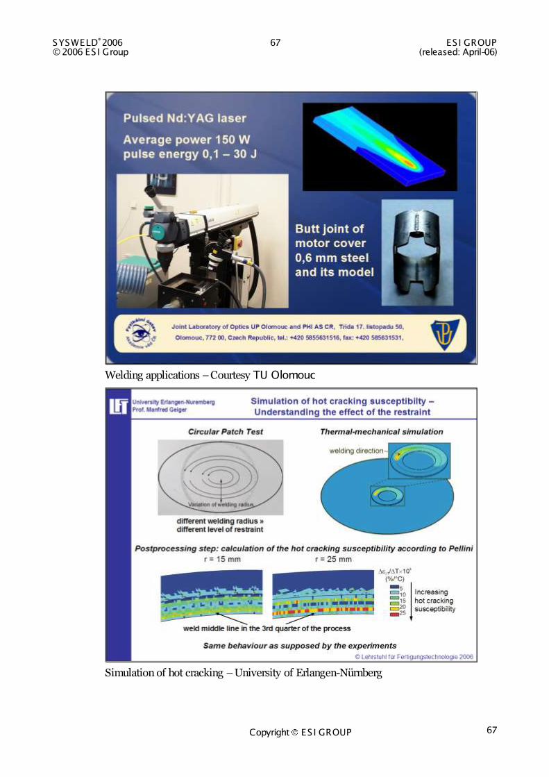
Welding applications – Courtesy TU Olomouc
SYSWELD®2006 67 ES I GROUP © 2006 ES I Group (released: April-06)
Copyright ES I GROUP 67
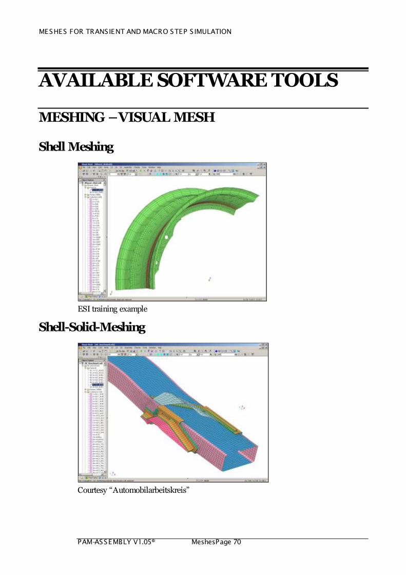
Welding applications – Courtesy TU Olomouc
Simulation of hot cracking – University of Erlangen-Nürnberg

ESI GROUP 68 SYSWELD®2006 (released: April-06) © 2006 ES I Group
Copyright ES I GROUP 68
Viscoplastic modeling – courtesy see slide
Viscoplastic modeling – courtesy see slide

SYSWELD®2006 69 ES I GROUP © 2006 ES I Group (released: April-06)
Copyright ES I GROUP 69
Welding of plastics – Courtesy Bayerisches Laserzentrum
MESHES FOR TRANSIENT AND MACRO STEP S IMULATION
PAM-ASSEMBLY V1.05® MeshesPage 70
AVAILABLE SOFTWARE TOOLS
MESHING – VISUAL MESH
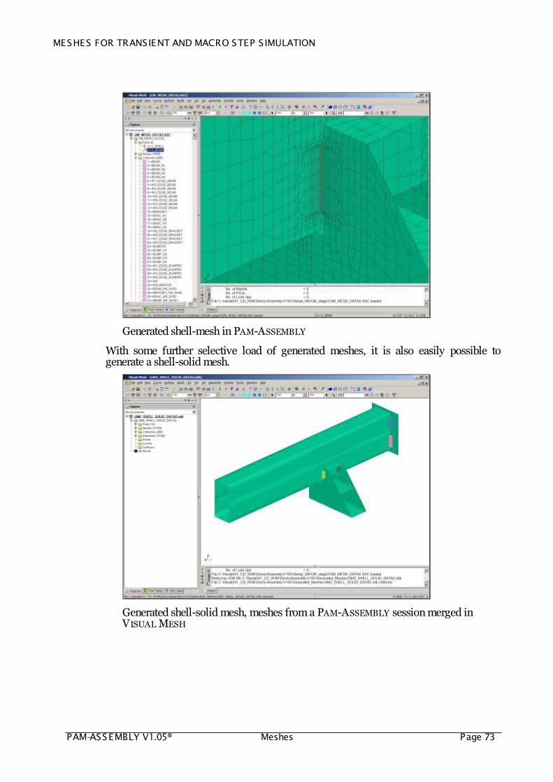
Shell Meshing
ESI training example
Shell-Solid-Meshing
Courtesy “Automobilarbeitskreis”

MESHES FOR TRANSIENT AND MACRO STEP S IMULATION
PAM-ASSEMBLY V1.05® Meshes Page 71
Solid-Meshing
Courtesy AUDI AG
Automatic Shell Meshing
Automatic (Batch) meshing of WELDING ASSEMBLY components, based on user defined rules – ESI example

MESHES FOR TRANSIENT AND MACRO STEP S IMULATION
PAM-ASSEMBLY V1.05® MeshesPage 72
Automatic Link of Shell Components with Solid Welding Joints
For the purpose of Welding Assembly, global components meshed only with shell elements are linked with so-called Welding Macro Elements, which are a brand new development. Shell meshing is not time consuming and the components are linked automatically via Welding Macro Elements. The inner forces resulting from a transient or steady state welding simulation of a local model are then transferred to the Welding Macro Elements and the assembly simulation is performed.
Automatic insertion of welding joints in shell meshed components - Courtesy RENAULT
How to Generate Quickly Meshes for Transient and Macro Step Welding Simulation
PAM-ASSEMBLY performs distortion simulation with a global mesh that consists of Welding Macro Elements and shell meshes of components. Temporarily, solid elements have been created to insert the Welding Macro Elements. Welding trajectories have been used to generate the temporary solid meshes by extrusion or block.
With VISUAL MESH, it is easily possible to generate from the generated meshes a shell only or shell-solid mesh for Classic Transient or Macro Step simulations. Only little organizational work is needed to generate the required meshes.
MESHES FOR TRANSIENT AND MACRO STEP S IMULATION
PAM-ASSEMBLY V1.05® Meshes Page 73
Generated shell-mesh in PAM-ASSEMBLY
With some further selective load of generated meshes, it is also easily possible to generate a shell-solid mesh.
Generated shell-solid mesh, meshes from a PAM-ASSEMBLY session merged in
VISUAL MESH

MESHES FOR TRANSIENT AND MACRO STEP S IMULATION
PAM-ASSEMBLY V1.05® MeshesPage 74
Generated shell-solid mesh, meshes from a PAM-ASSEMBLY session merged in
VISUAL MESH

MESHES FOR TRANSIENT AND MACRO STEP S IMULATION
PAM-ASSEMBLY V1.05® Meshes Page 75
TRANSIENT AND STEADY STATE WELDING
Welding Wizard
The Welding Wizard is an easy-to-use Graphical User Interface to facilitate the efficient set-up of welding simulations. No knowledge in Finite Element methods is needed to set up and run steady state and transient welding simulations. It combines a mesh, material data information from a material database, heat source information from a heat source database and individual process parameters in a way that input decks are created that can be automatically interpreted by the SYSWELD solver. The input decks consist of the definition of material properties, constraints and loads, and the command sequence for the solver.
The Welding Wizard dialogue box
MESHES FOR TRANSIENT AND MACRO STEP S IMULATION
PAM-ASSEMBLY V1.05® MeshesPage 76
Local Model Wizard
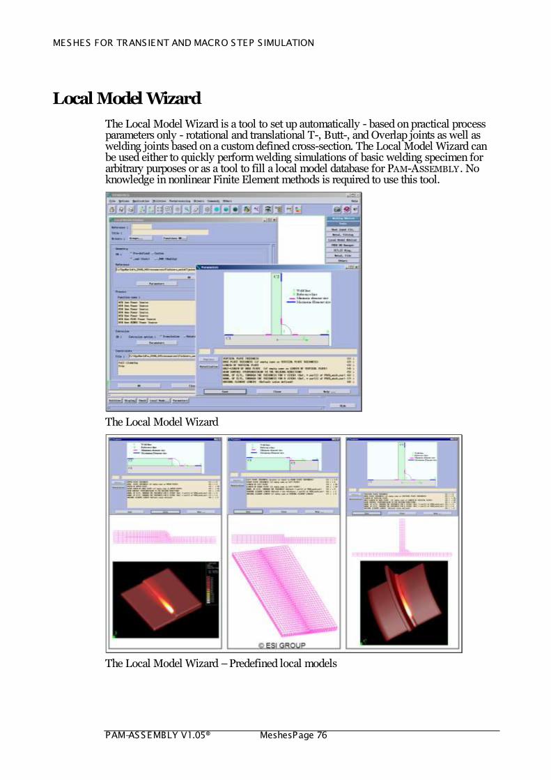
The Local Model Wizard is a tool to set up automatically - based on practical process parameters only - rotational and translational T-, Butt-, and Overlap joints as well as welding joints based on a custom defined cross-section. The Local Model Wizard can be used either to quickly perform welding simulations of basic welding specimen for arbitrary purposes or as a tool to fill a local model database for PAM-ASSEMBLY . No knowledge in nonlinear Finite Element methods is required to use this tool.
The Local Model Wizard
The Local Model Wizard – Predefined local models

MESHES FOR TRANSIENT AND MACRO STEP S IMULATION
PAM-ASSEMBLY V1.05® Meshes Page 77
Heat Source Fitting Tool
The calibration of the heat transfer into the structure is one of the most important tasks in a welding (assembly) simulation. To check the process feasibility is however not the task of the engineer in this context – welding assembly simulation means computation of the heat effects of welding rather then process feasibility simulation. Consequently – for the purpose of the computation of the heat effects of welding - welding joints can be assumed that can be manufactured under valid process conditions, as for example described in American, Japanese or European norms. The task of the heat source fitting tool is to find - based on a heat transfer model - process parameters in a way that valid joints are produced. A fine tuning can be done based on micrographs and temperature and hardness measurements. Four joint profiles are predefined to fit the heat source: T, Butt, Overlap and User Defined. An automatic post-processing provides you with the most important results. The calibrated heat source can be stored in a database and used later for arbitrary purposes.
The Heat Source Fitting tool
MESHES FOR TRANSIENT AND MACRO STEP S IMULATION
PAM-ASSEMBLY V1.05® MeshesPage 78
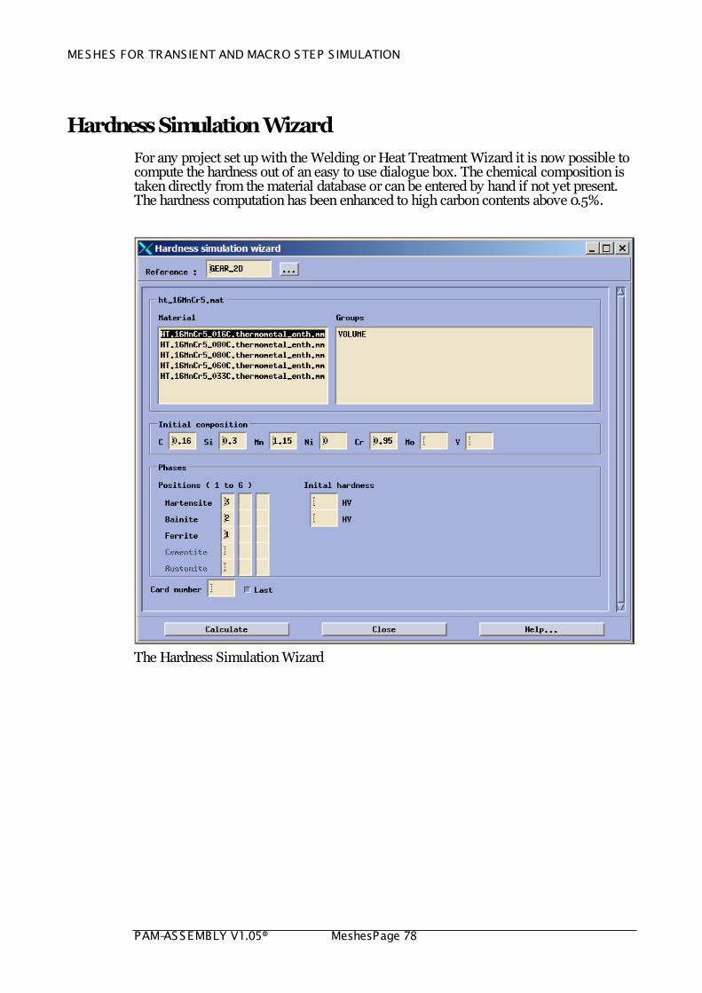
Hardness Simulation Wizard
For any project set up with the Welding or Heat Treatment Wizard it is now possible to compute the hardness out of an easy to use dialogue box. The chemical composition is taken directly from the material database or can be entered by hand if not yet present. The hardness computation has been enhanced to high carbon contents above 0.5%.
The Hardness Simulation Wizard
MESHES FOR TRANSIENT AND MACRO STEP S IMULATION
PAM-ASSEMBLY V1.05® Meshes Page 79
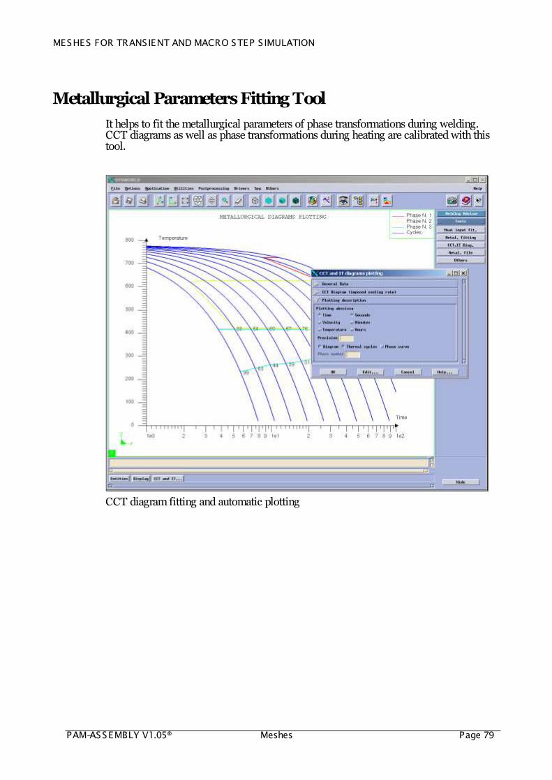
Metallurgical Parameters Fitting Tool
It helps to fit the metallurgical parameters of phase transformations during welding. CCT diagrams as well as phase transformations during heating are calibrated with this tool.
CCT diagram fitting and automatic plotting

MESHES FOR TRANSIENT AND MACRO STEP S IMULATION
PAM-ASSEMBLY V1.05® MeshesPage 80
Multi-Pass Welding
Multi Pass Welding Joints are a very important part of steel constructions and pressure vessel components. Defects occur very often in them. Residual tensile stresses have negative influence on the structure lifetime and the brittle fracture resistance. Residual stresses create a balanced system of inner forces, which exists even under no external loading. The welding joints have to designed and produced with care.
ESI group has developed a multi-pass Wizard that helps the user to manage multi-pass welding. It simplifies significantly the workload of the user. All welds involved in the multi-pass process are computed according to the same scheme initially defined in the Welding Wizard. When the project is saved the mesh is checked, updated and all input data for all welding simulation are created.
Tools for Multi-pass Welding
By using the check dialog box, after the selection of the welding project, the list of welding joint is proposed. The mesh that will be used for the computation of the selected joint is updated such as the standard ‘Check’ procedure can be used.
Tools for Multi-pass Welding
After the selection of the welding project, the Solve editor box is opened. The „solve as a single weld‟ option allows to run the computation of the selected joint independently of all previous one. This option must be used for a checking purpose. The list of the joints to be computed must be selected before validation. For the whole simulation, all welds must be selected.

MESHES FOR TRANSIENT AND MACRO STEP S IMULATION
PAM-ASSEMBLY V1.05® Meshes Page 81
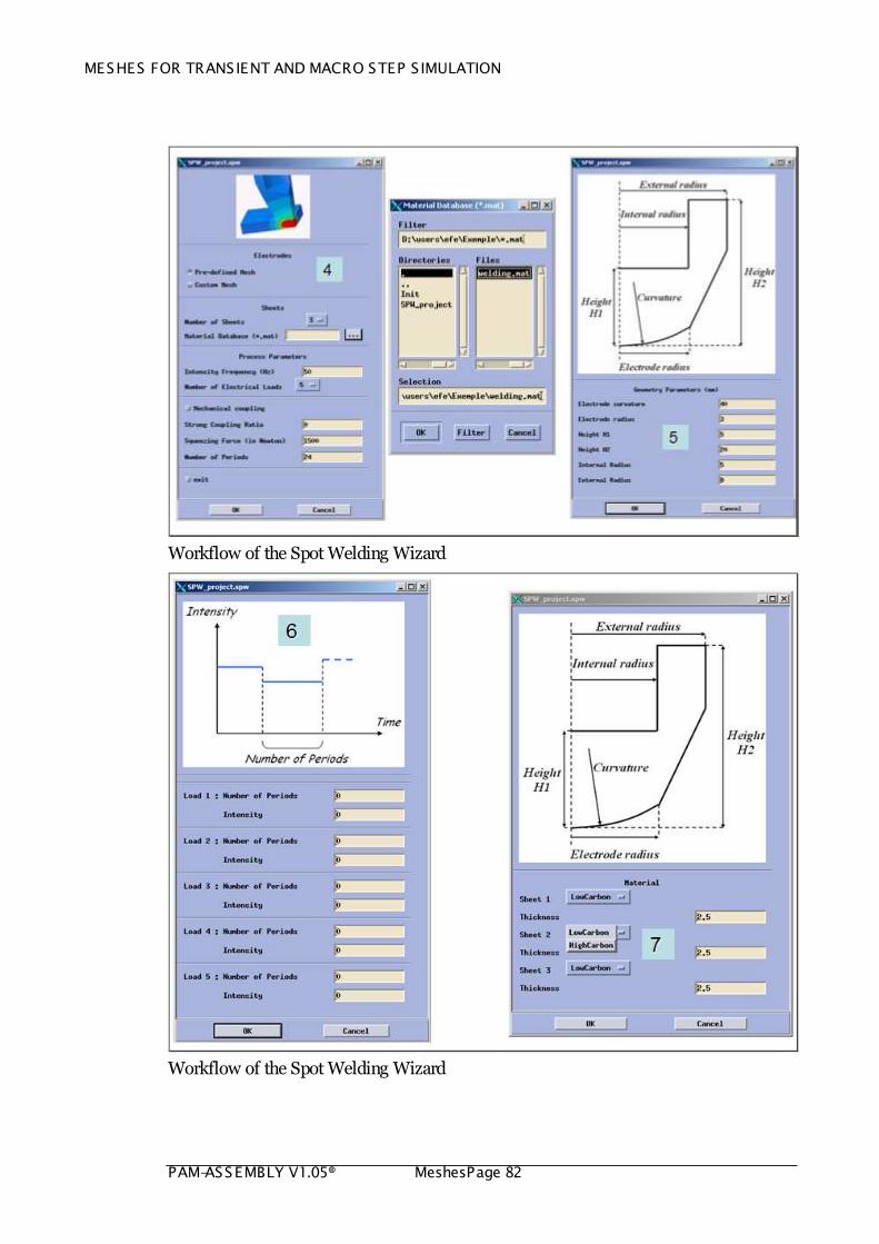
Spot Welding
Resistance spot welding is an efficient process to join vehicle body parts. This process involves strong interactions between electrical, thermal, metallurgical, and mechanical phenomena. With the coupling between electromagnetism, heat transfer, metallurgy, and mechanics, this process is accurately simulated with SYSWELD.
This numerical approach makes it also possible to account for the evolutions of the contact surfaces. The electro-thermal contact conditions are affected on a macroscopic scale by the evolution of the contact surfaces but also on a microscopic scale in the evolution of electro thermal contact resistances.
Comparison between numerical (Blue and Red line) and experimental nugget size at the end of heating
It is important to note that this simulation can be considered as a local model and repeated several time on a global model by using local global approach. The main interest is to analyze and optimize, with very short computation time, the welding sequences in order to reduce on the global distortion.
A Spot Welding Wizard has been developed to simplify the set up of spot welding simulations
Workflow of the Spot Welding Wizard
MESHES FOR TRANSIENT AND MACRO STEP S IMULATION
PAM-ASSEMBLY V1.05® MeshesPage 82
Workflow of the Spot Welding Wizard
Workflow of the Spot Welding Wizard

MESHES FOR TRANSIENT AND MACRO STEP S IMULATION
PAM-ASSEMBLY V1.05® Meshes Page 83
MESHES FOR TRANSIENT AND MACRO STEP S IMULATION
PAM-ASSEMBLY V1.05® MeshesPage 84
Friction Stir Welding
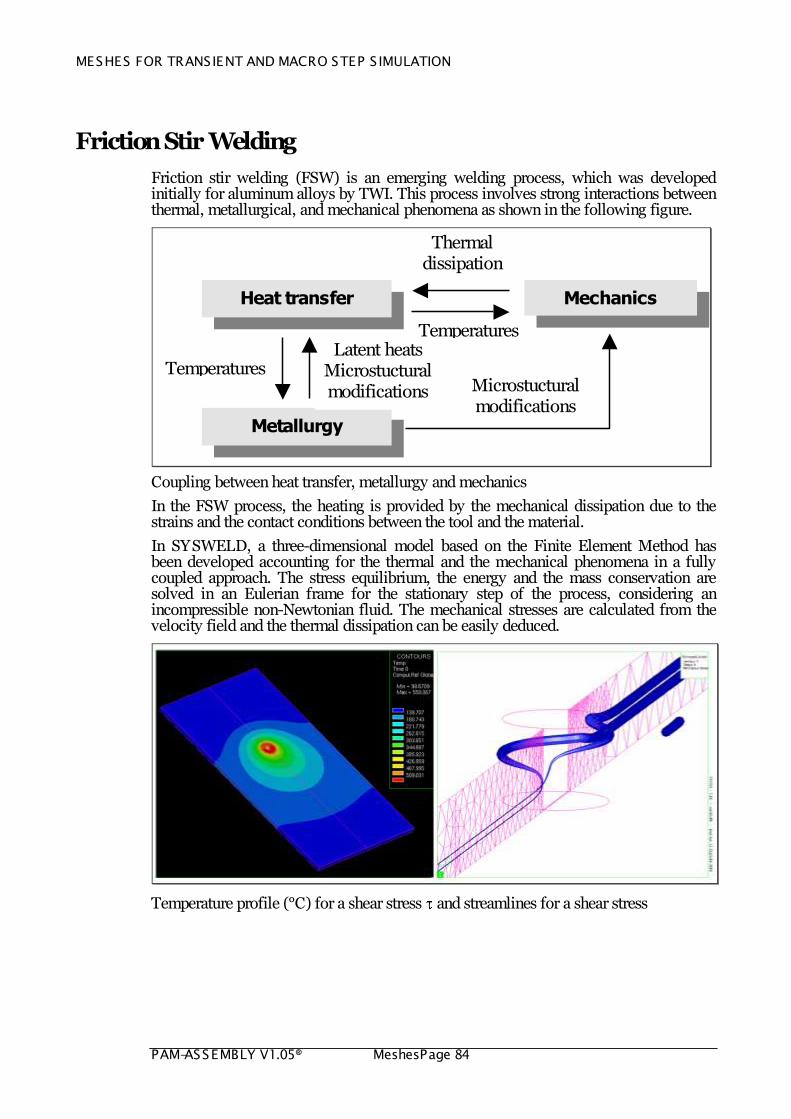
Friction stir welding (FSW) is an emerging welding process, which was developed initially for aluminum alloys by TWI. This process involves strong interactions between thermal, metallurgical, and mechanical phenomena as shown in the following figure.
Mechanics
Temperatures
Heat transfer
Metallurgy
Latent heats Microstuctural modifications
Microstuctural modifications
Thermal dissipation
Temperatures
Coupling between heat transfer, metallurgy and mechanics
In the FSW process, the heating is provided by the mechanical dissipation due to the strains and the contact conditions between the tool and the material.
In SYSWELD, a three-dimensional model based on the Finite Element Method has been developed accounting for the thermal and the mechanical phenomena in a fully coupled approach. The stress equilibrium, the energy and the mass conservation are solved in an Eulerian frame for the stationary step of the process, considering an incompressible non-Newtonian fluid. The mechanical stresses are calculated from the velocity field and the thermal dissipation can be easily deduced.
Temperature profile (°C) for a shear stress and streamlines for a shear stress

MESHES FOR TRANSIENT AND MACRO STEP S IMULATION
PAM-ASSEMBLY V1.05® Meshes Page 85
Welding Material Databases
The welding solution from ESI comes with a database that incorporates the most commonly used materials in the Industry.
The material data can be managed in Microsoft Excel . A Macro exists which exports material data in the SYSWELD database format.
Phase transformation and melting enthalpy
Material data management in Microsoft Excel

MESHES FOR TRANSIENT AND MACRO STEP S IMULATION
PAM-ASSEMBLY V1.05® MeshesPage 86
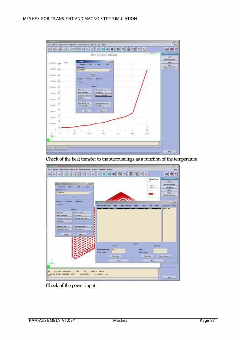
Check Box
The check box is a tool to check simulation projects that have been set up with the Welding Wizard. All necessary checks are available through one dialogue box.
Check of the Weld-line
Check of the heat exchange with the surroundings
MESHES FOR TRANSIENT AND MACRO STEP S IMULATION
PAM-ASSEMBLY V1.05® Meshes Page 87
Check of the heat transfer to the surroundings as a function of the temperature
Check of the power input

MESHES FOR TRANSIENT AND MACRO STEP S IMULATION
PAM-ASSEMBLY V1.05® MeshesPage 88
Check of the applied power density
Check of material groups

MESHES FOR TRANSIENT AND MACRO STEP S IMULATION
PAM-ASSEMBLY V1.05® Meshes Page 89
Check of the clamping conditions
Check of material properties
MESHES FOR TRANSIENT AND MACRO STEP S IMULATION
PAM-ASSEMBLY V1.05® MeshesPage 90
MACRO STEP WELDING
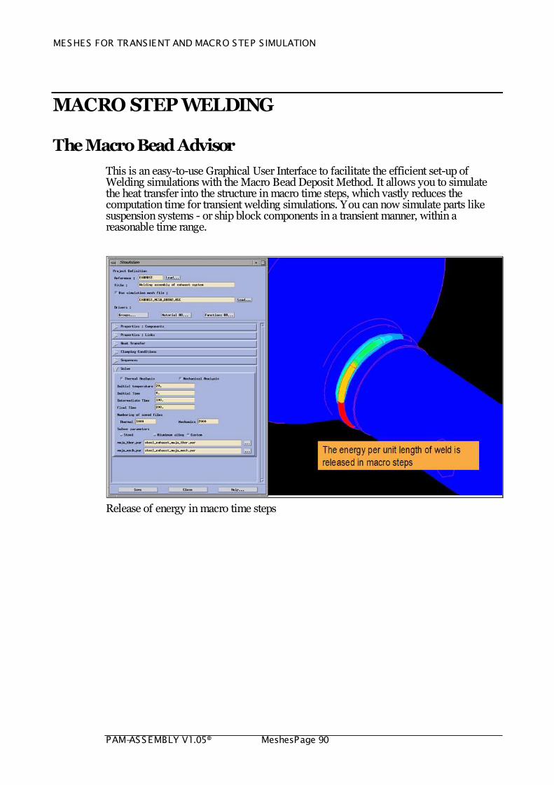
The Macro Bead Advisor
This is an easy-to-use Graphical User Interface to facilitate the efficient set-up of Welding simulations with the Macro Bead Deposit Method. It allows you to simulate the heat transfer into the structure in macro time steps, which vastly reduces the computation time for transient welding simulations. You can now simulate parts like suspension systems - or ship block components in a transient manner, within a reasonable time range.
Release of energy in macro time steps

MESHES FOR TRANSIENT AND MACRO STEP S IMULATION
PAM-ASSEMBLY V1.05® Meshes Page 91
WELDING ASSEMBLY
The Assembly Advisor
This is an easy-to-use Graphical User Interface to facilitate the efficient set-up of Welding Assembly simulations. The Welding Assembly Advisor opens a huge simulation application field – distortion control of large maritime and automotive structures with a reasonable amount of computer memory and computation of results within a extremely short time range.
The Welding Assembly Advisor was the first tool that enabled to use the local-global method for the simulation of Welding Assembly. Starting from 2006, PAM-ASSEMBLY is available for the set up of Welding Assembly simulations. The Welding Assembly Advisor in SYSWELD will remain; It allows the definition of very complex simulations, which require sometimes an advanced knowledge in the method of Finite Elements.
The Welding Assembly Advisor

MESHES FOR TRANSIENT AND MACRO STEP S IMULATION
PAM-ASSEMBLY V1.05® MeshesPage 92
PAM-ASSEMBLY Database Manager
This is a tool to manage local models to be used by PAM-ASSEMBLY and computed with SYSWELD. It has been designed within SYSWELD to fill a local model database for PAM-ASSEMBLY with results computed with the help of the Local Model Advisor.
Export of local models in SYSWELD
Import of local models in PAM-ASSEMBLY
PAM-ASSEMBLY

MESHES FOR TRANSIENT AND MACRO STEP S IMULATION
PAM-ASSEMBLY V1.05® Meshes Page 93
PAM-ASSEMBLY is a new integrated solution for the simulation of Welding Assembly. The main purpose of this tool is to compute the displacements after each step of an assembly sequence and unclamping. Using PAM-ASSEMBLY , the user is able to optimize, compare and finally select the best possible welding sequence and choice of clamping tools.
In PAM-ASSEMBLY , the Local-Global method is applied to simulate the effects of Welding Assembly. It is the most efficient method for large assembly designs.
PAM-ASSEMBLY graphical user interface
AVAILABLE ENGINEERING TOOLS
MESHES FOR TRANSIENT AND MACRO STEP S IMULATION
PAM-ASSEMBLY V1.05® MeshesPage 94
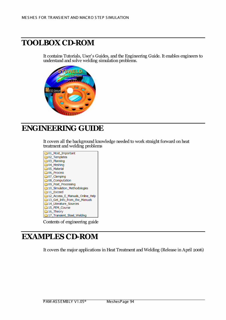
TOOLBOX CD-ROM
It contains Tutorials, User‟s Guides, and the Engineering Guide. It enables engineers to understand and solve welding simulation problems.
ENGINEERING GUIDE
It covers all the background knowledge needed to work straight forward on heat treatment and welding problems
Contents of engineering guide
EXAMPLES CD-ROM
It covers the major applications in Heat Treatment and Welding (Release in April 2006)
MESHES FOR TRANSIENT AND MACRO STEP S IMULATION
PAM-ASSEMBLY V1.05® Meshes Page 95
DOCUMENTATION
WELDING USER’S GUIDE
The Welding User‟s guide covers the usage of the Welding Wizard as well as all the engineering knowledge related to steady state and transient welding.
Welding User‟s Guide
MESHES FOR TRANSIENT AND MACRO STEP S IMULATION
PAM-ASSEMBLY V1.05® MeshesPage 96
KNOWLEDGE INCLUDED
Usage of the Welding Wizard
Messages Managed by the Welding Wizard
How to Choose Numerical Parameter Files
Frequently asked questions
Way to Work
The Most Important Tips and Tricks
Guidelines for Large Problems
Guidelines for Transient Welding of Shells
Advanced Welding Modeling
Access to Electronic Manuals – Getting Info from Manuals
Quick Checklist
A Tutorial – Keys to Convergence
Step by Step Example
Systematical Example
How to Present Results in an Effective Format
Typical Postprocessing Results
MESHES FOR TRANSIENT AND MACRO STEP S IMULATION
PAM-ASSEMBLY V1.05® Meshes Page 97
KEY TECHNOLOGY
SIMULATED PHYSICS
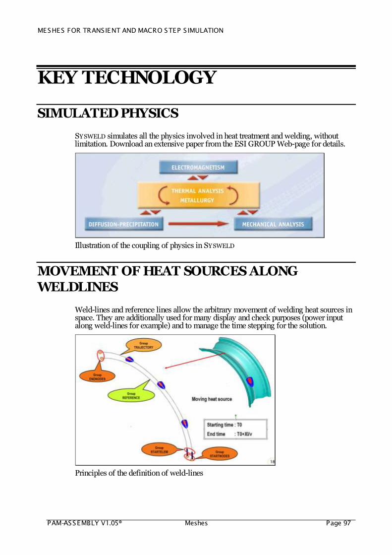
SYSWELD simulates all the physics involved in heat treatment and welding, without limitation. Download an extensive paper from the ESI GROUP Web-page for details.
Illustration of the coupling of physics in SYSWELD
MOVEMENT OF HEAT SOURCES ALONG WELDLINES
Weld-lines and reference lines allow the arbitrary movement of welding heat sources in space. They are additionally used for many display and check purposes (power input along weld-lines for example) and to manage the time stepping for the solution.
Principles of the definition of weld-lines
MESHES FOR TRANSIENT AND MACRO STEP S IMULATION
PAM-ASSEMBLY V1.05® MeshesPage 98
REMOVAL OF MATERIAL HISTORY
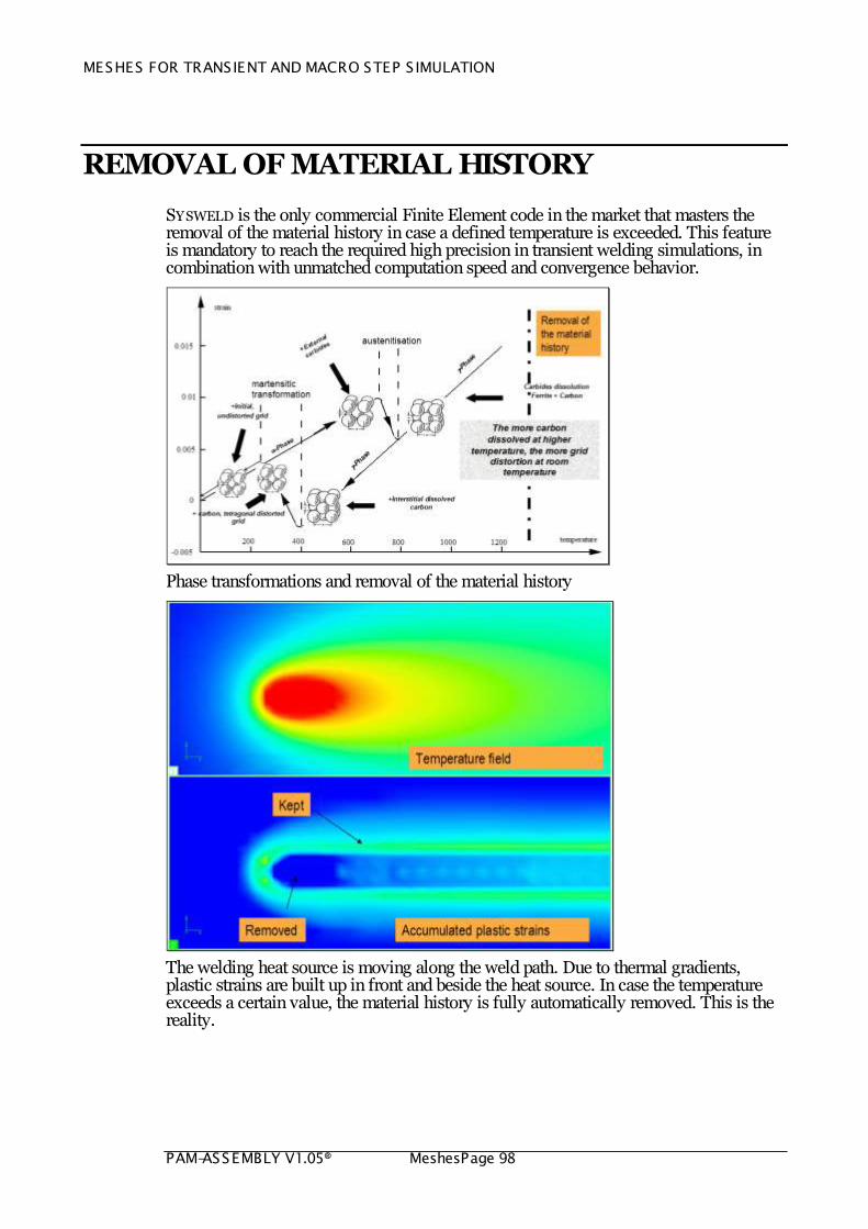
SYSWELD is the only commercial Finite Element code in the market that masters the removal of the material history in case a defined temperature is exceeded. This feature is mandatory to reach the required high precision in transient welding simulations, in combination with unmatched computation speed and convergence behavior.
Phase transformations and removal of the material history
The welding heat source is moving along the weld path. Due to thermal gradients, plastic strains are built up in front and beside the heat source. In case the temperature exceeds a certain value, the material history is fully automatically removed. This is the reality.
MESHES FOR TRANSIENT AND MACRO STEP S IMULATION
PAM-ASSEMBLY V1.05® Meshes Page 99
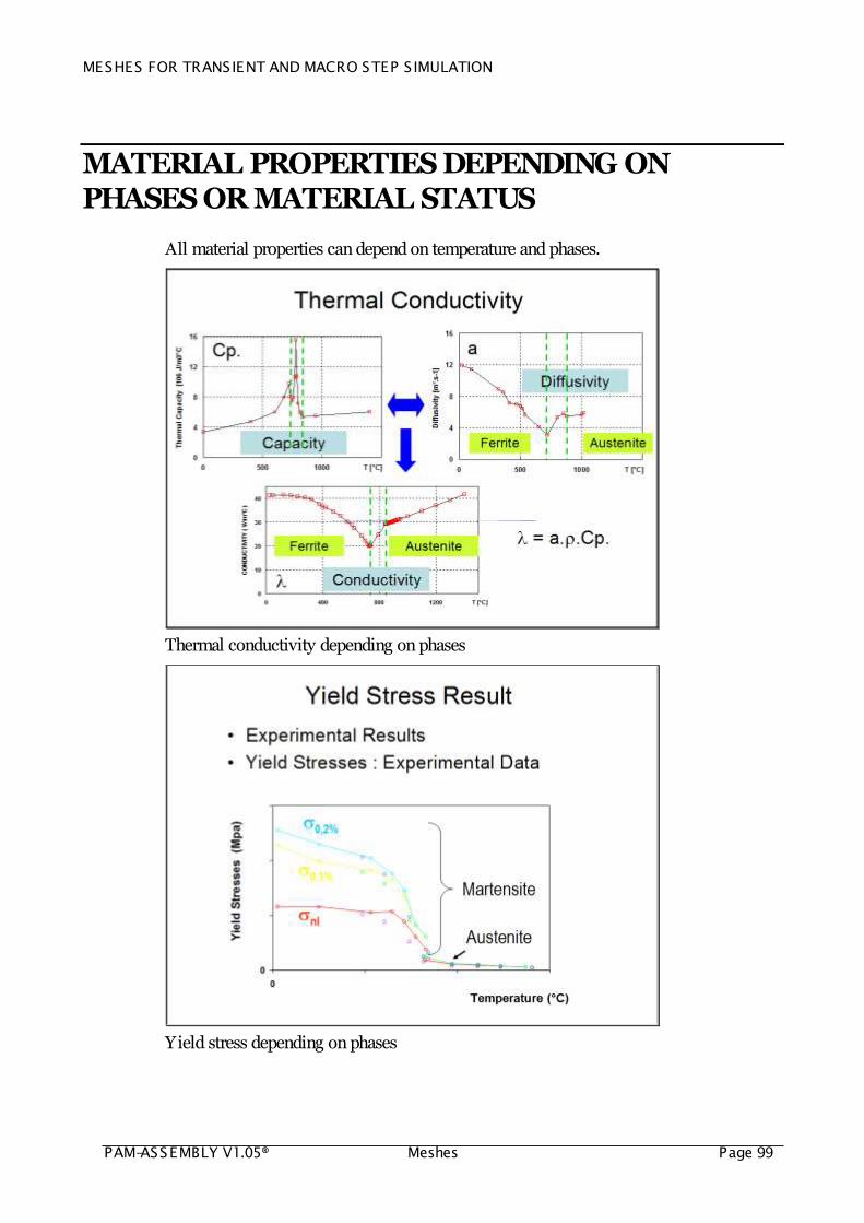
MATERIAL PROPERTIES DEPENDING ON PHASES OR MATERIAL STATUS
All material properties can depend on temperature and phases.
Thermal conductivity depending on phases
Yield stress depending on phases
MESHES FOR TRANSIENT AND MACRO STEP S IMULATION
PAM-ASSEMBLY V1.05® MeshesPage 100
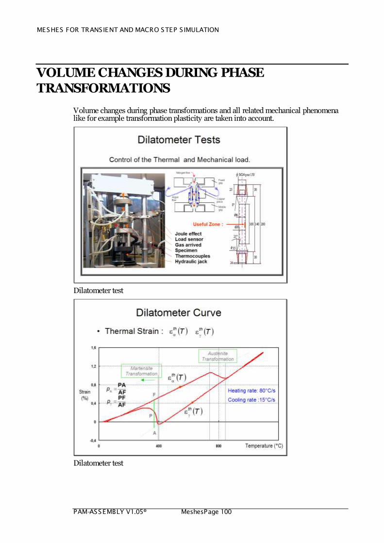
VOLUME CHANGES DURING PHASE TRANSFORMATIONS
Volume changes during phase transformations and all related mechanical phenomena like for example transformation plasticity are taken into account.
Dilatometer test
Dilatometer test
MESHES FOR TRANSIENT AND MACRO STEP S IMULATION
PAM-ASSEMBLY V1.05® Meshes Page 101
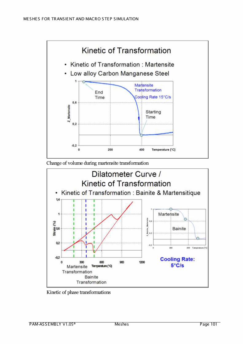
Change of volume during martensite transformation
Kinetic of phase transformations

MESHES FOR TRANSIENT AND MACRO STEP S IMULATION
PAM-ASSEMBLY V1.05® MeshesPage 102
PHASE TRANSFORMATIONS OF HARDENABLE STEEL
Isothermal and continuous phase transformations of hardenable steel are taken into account.
CCT diagram of hardenable steel
Simulated phase transformations

MESHES FOR TRANSIENT AND MACRO STEP S IMULATION
PAM-ASSEMBLY V1.05® Meshes Page 103
CCT and TTT diagram
ALMGMN – KINETICS OF RECRYSTALLIZATION
The hardening due to mechanical treatment and the loss of hardening due to the heat effects of welding is treated in welding simulations.
Loss of strength due to recovery effects

MESHES FOR TRANSIENT AND MACRO STEP S IMULATION
PAM-ASSEMBLY V1.05® MeshesPage 104
ALMGSI – KINETICS OF PRECIPITATES
The precipitation hardening and the loss of hardening due to the heat effects of welding is treated in welding simulations.
Loss of strength due to dissolution of precipitations
DEDICATED MECHANICAL MATERIAL LAWS
All mechanical phenomena that occur in a welding process are accurately simulated.
Implemented mechanical models

MESHES FOR TRANSIENT AND MACRO STEP S IMULATION
PAM-ASSEMBLY V1.05® Meshes Page 105
Implemented hardening laws
The plastic behaviour model of steel during transformation presented above has been extended to take into account the viscous-plastic phenomena. They are introduced by making the yield stress of the phases depending on the rate of plastic deformation. The numerical implementation allows that elastic - plastic and elastic – viscous-plastic behaviors can be combined. The resulting model proposes a strain hardening both in additive and multiplicative form.
Viscous plastic model
MESHES FOR TRANSIENT AND MACRO STEP S IMULATION
PAM-ASSEMBLY V1.05® MeshesPage 106
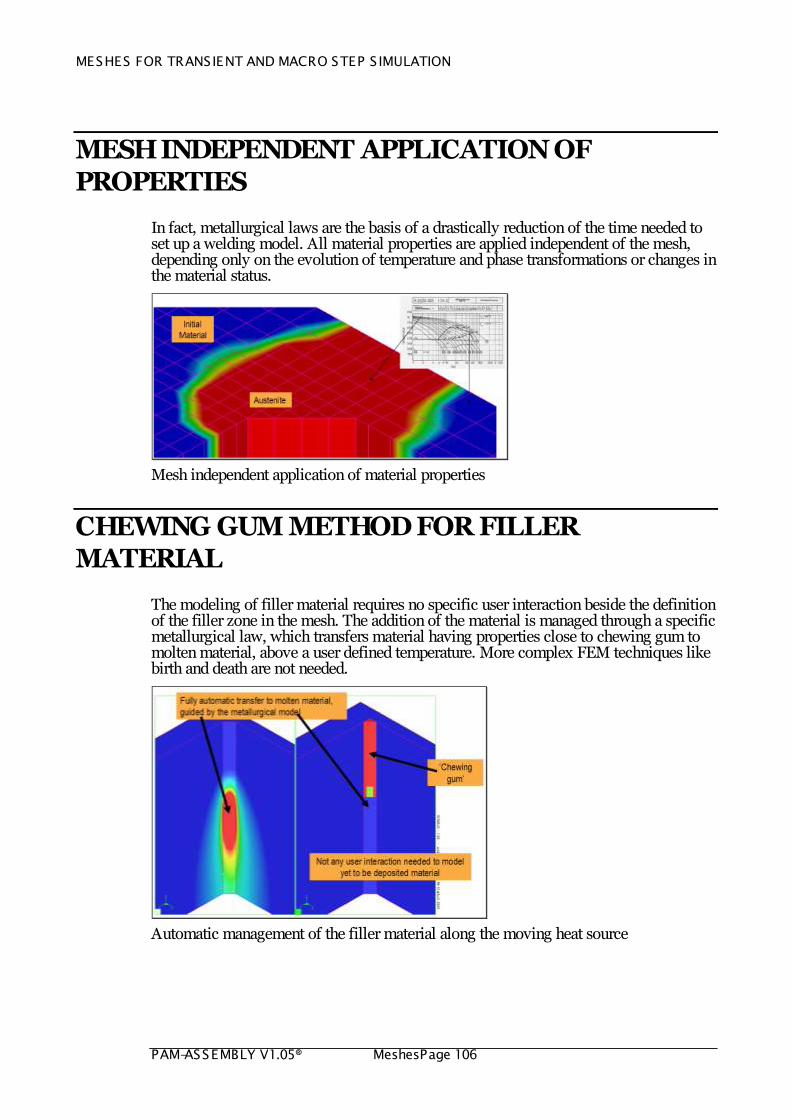
MESH INDEPENDENT APPLICATION OF PROPERTIES
In fact, metallurgical laws are the basis of a drastically reduction of the time needed to set up a welding model. All material properties are applied independent of the mesh, depending only on the evolution of temperature and phase transformations or changes in the material status.
Mesh independent application of material properties
CHEWING GUM METHOD FOR FILLER MATERIAL
The modeling of filler material requires no specific user interaction beside the definition of the filler zone in the mesh. The addition of the material is managed through a specific metallurgical law, which transfers material having properties close to chewing gum to molten material, above a user defined temperature. More complex FEM techniques like birth and death are not needed.
Automatic management of the filler material along the moving heat source
MESHES FOR TRANSIENT AND MACRO STEP S IMULATION
PAM-ASSEMBLY V1.05® Meshes Page 107
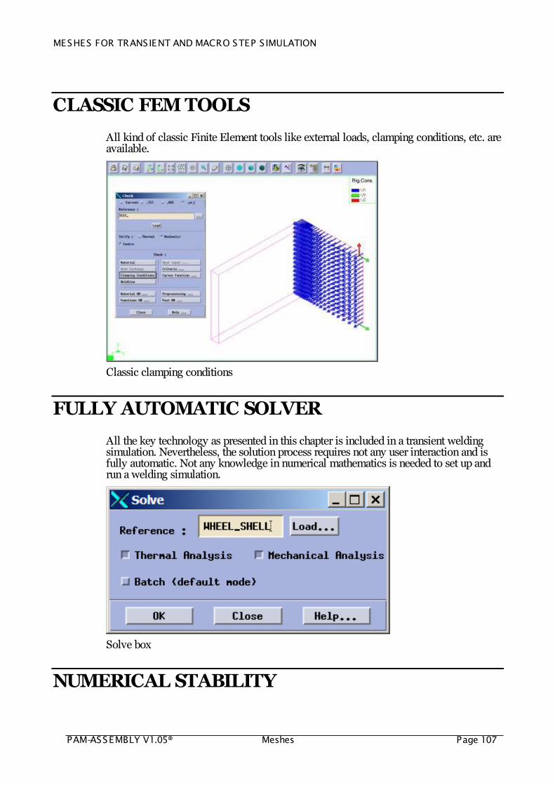
CLASSIC FEM TOOLS
All kind of classic Finite Element tools like external loads, clamping conditions, etc. are available.
Classic clamping conditions
FULLY AUTOMATIC SOLVER
All the key technology as presented in this chapter is included in a transient welding simulation. Nevertheless, the solution process requires not any user interaction and is fully automatic. Not any knowledge in numerical mathematics is needed to set up and run a welding simulation.
Solve box
NUMERICAL STABILITY
MESHES FOR TRANSIENT AND MACRO STEP S IMULATION
PAM-ASSEMBLY V1.05® MeshesPage 108
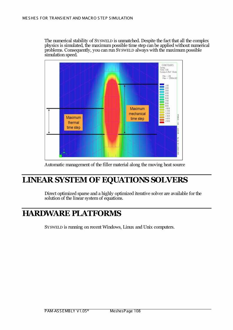
The numerical stability of SYSWELD is unmatched. Despite the fact that all the complex physics is simulated, the maximum possible time step can be applied without numerical problems. Consequently, you can run SYSWELD always with the maximum possible simulation speed.
Automatic management of the filler material along the moving heat source
LINEAR SYSTEM OF EQUATIONS SOLVERS
Direct optimized sparse and a highly optimized iterative solver are available for the solution of the linear system of equations.
HARDWARE PLATFORMS
SYSWELD is running on recent Windows, Linux and Unix computers.
MESHES FOR TRANSIENT AND MACRO STEP S IMULATION
PAM-ASSEMBLY V1.05® Meshes Page 109
SUMMARY – TECHNICAL FEATURES AND KEY TECHNOLOGY
Movement of welding heat sources along arbitrary path in space
Automatic and mesh independent calibration of the heat transferred into the structure along the weld path
Phase transformation and melting enthalpy
Phase and material status dependent material properties
Fully automatic treatment of removal and birth of material history
Fully automatic and mesh independent application of material properties depending on temperature and phases
Fully automatic treatment of yet to be deposited material
Nonlinear mixture rules for phase properties
Restoring of strain hardening during transformation
Dedicated integration of plasticity laws
Nonlinear geometry (large strains and large displacements/rotations)
Consistent tangent material matrix for isotropic, kinematic and mixed hardening, including phase transformations
An iterative linear system of equation solver allows the treatment of very large structures on PC‟s
Generalized plane to plane contact
Linear and parabolic solid elements, linear solid elements with incompatible modes, linear and parabolic shell elements
Shell-solid models
Welding dedicated numerical tools
Welding simulation tools for all kinds of Industry and all kinds of metallic material

MESHES FOR TRANSIENT AND MACRO STEP S IMULATION
PAM-ASSEMBLY V1.05® MeshesPage 110
ILLUSTRATION – TECHNICAL FEATURES AND KEY TECHNOLOGY
Temperature field
Filler material modeling
MESHES FOR TRANSIENT AND MACRO STEP S IMULATION
PAM-ASSEMBLY V1.05® Meshes Page 111
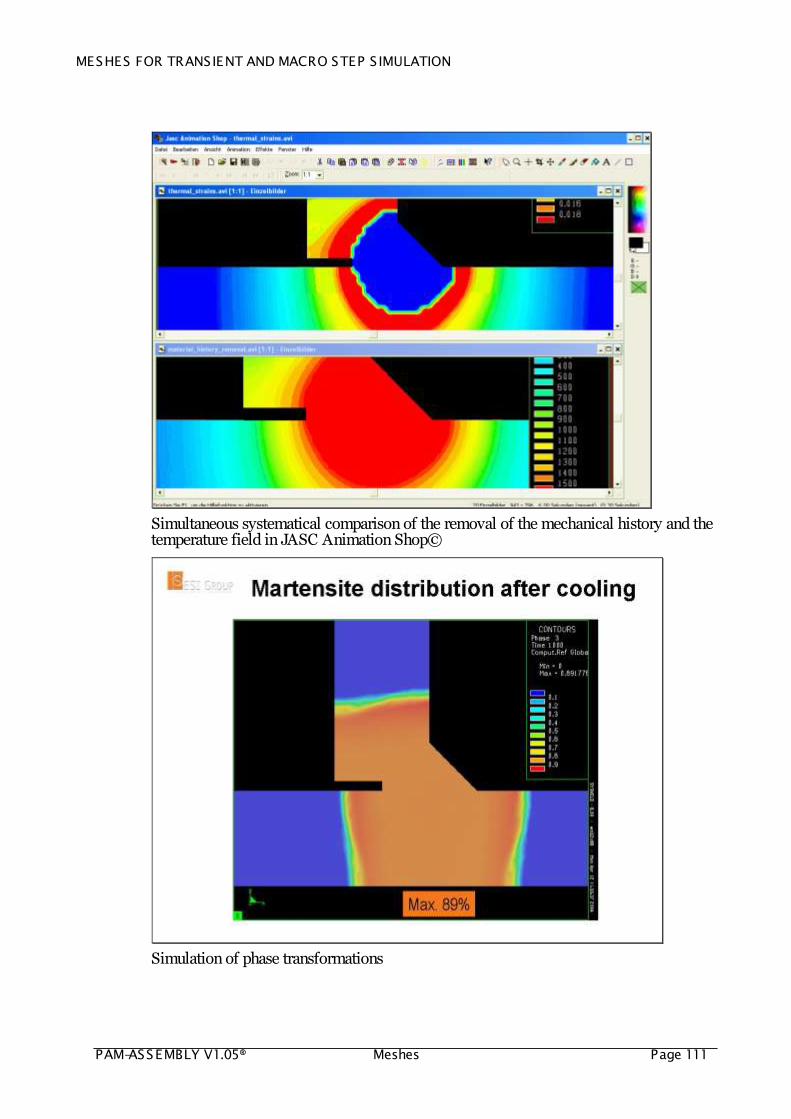
Simultaneous systematical comparison of the removal of the mechanical history and the temperature field in JASC Animation Shop©
Simulation of phase transformations
MESHES FOR TRANSIENT AND MACRO STEP S IMULATION
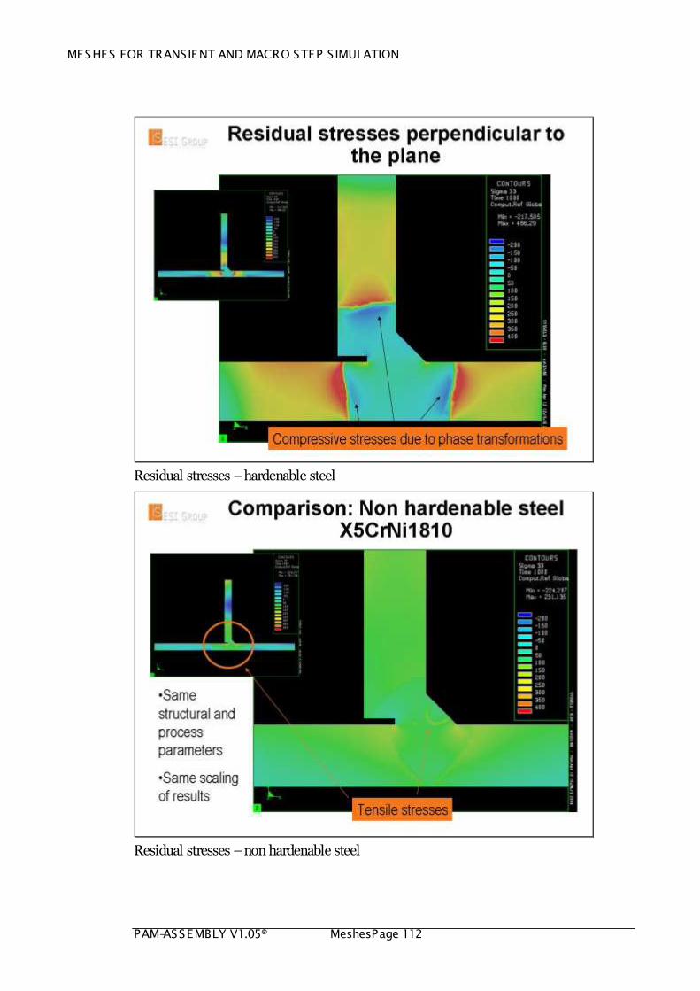
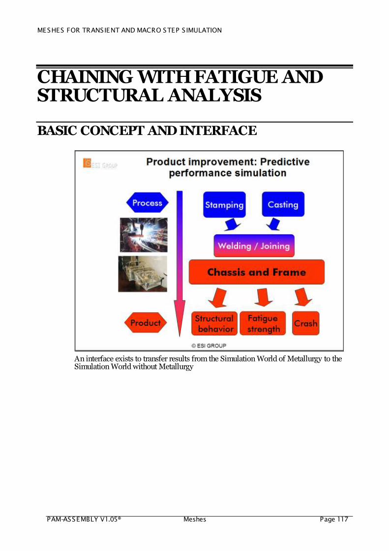
PAM-ASSEMBLY V1.05® MeshesPage 112
Residual stresses – hardenable steel
Residual stresses – non hardenable steel

MESHES FOR TRANSIENT AND MACRO STEP S IMULATION
PAM-ASSEMBLY V1.05® Meshes Page 113
Cumulated plastic strains
Final yield stress distribution

MESHES FOR TRANSIENT AND MACRO STEP S IMULATION
PAM-ASSEMBLY V1.05® MeshesPage 114
Residual stresses after tempering
Change of process conditions and wall thickness

MESHES FOR TRANSIENT AND MACRO STEP S IMULATION
PAM-ASSEMBLY V1.05® Meshes Page 115
CHAINING WITH STAMPING AND CRASH SIMULATION
CHAINING STAMPING AND WELDING
The basic goal of distortion engineering
Chaining of stamping and welding simulation

MESHES FOR TRANSIENT AND MACRO STEP S IMULATION
PAM-ASSEMBLY V1.05® MeshesPage 116
CHAINING WELDING AND STAMPING
Chaining of welding and stamping simulation – Courtesy AUDI AG
CHAINING WELDING AND CRASH
Chaining of welding and crash simulation
MESHES FOR TRANSIENT AND MACRO STEP S IMULATION
PAM-ASSEMBLY V1.05® Meshes Page 117
CHAINING WITH FATIGUE AND STRUCTURAL ANALYSIS
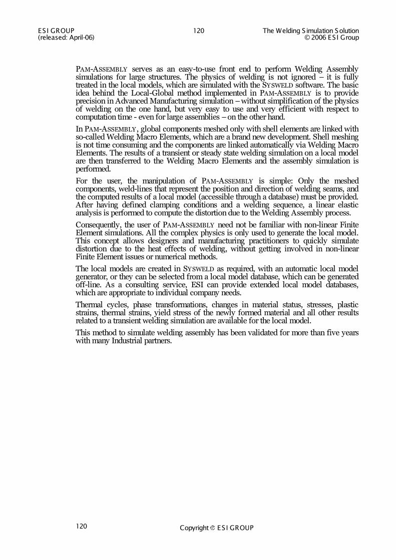
BASIC CONCEPT AND INTERFACE
An interface exists to transfer results from the Simulation World of Metallurgy to the Simulation World without Metallurgy

ESI GROUP 118 The Welding S imulation Solution (released: April-06) © 2006 ES I Group
Copyright ES I GROUP 118
WELDING-ASSEMBLY OF LARGE STRUCTURES
OVERVIEW
PAM-ASSEMBLY is a new integrated solution for the simulation of Welding Assembly of large structures. The main purpose of this tool is to compute the displacements after each step of an assembly sequence and unclamping. Using PAM-ASSEMBLY , the user is able to optimize, compare and finally select the best possible welding sequence and choice of clamping tools.
In PAM-ASSEMBLY , the Local-Global method is applied to simulate the effects of Welding Assembly. It is the most efficient method for large assembly designs.
General view of the Pam-Assembly Graphical User Interface

The Welding S imulation Solution 119 ES I GROUP © 2006 ES I Group (released: April-06)
Copyright ES I GROUP 119
BASIC CONCEPT
ESI GROUP 120 The Welding S imulation Solution (released: April-06) © 2006 ES I Group
Copyright ES I GROUP 120
PAM-ASSEMBLY serves as an easy-to-use front end to perform Welding Assembly simulations for large structures. The physics of welding is not ignored – it is fully treated in the local models, which are simulated with the SYSWELD software. The basic idea behind the Local-Global method implemented in PAM-ASSEMBLY is to provide precision in Advanced Manufacturing simulation – without simplification of the physics of welding on the one hand, but very easy to use and very efficient with respect to computation time - even for large assemblies – on the other hand.
In PAM-ASSEMBLY , global components meshed only with shell elements are linked with so-called Welding Macro Elements, which are a brand new development. Shell meshing is not time consuming and the components are linked automatically via Welding Macro Elements. The results of a transient or steady state welding simulation on a local model are then transferred to the Welding Macro Elements and the assembly simulation is performed.
For the user, the manipulation of PAM-ASSEMBLY is simple: Only the meshed components, weld-lines that represent the position and direction of welding seams, and the computed results of a local model (accessible through a database) must be provided. After having defined clamping conditions and a welding sequence, a linear elastic analysis is performed to compute the distortion due to the Welding Assembly process.
Consequently, the user of PAM-ASSEMBLY need not be familiar with non-linear Finite Element simulations. All the complex physics is only used to generate the local model. This concept allows designers and manufacturing practitioners to quickly simulate distortion due to the heat effects of welding, without getting involved in non-linear Finite Element issues or numerical methods.
The local models are created in SYSWELD as required, with an automatic local model generator, or they can be selected from a local model database, which can be generated off-line. As a consulting service, ESI can provide extended local model databases, which are appropriate to individual company needs.
Thermal cycles, phase transformations, changes in material status, stresses, plastic strains, thermal strains, yield stress of the newly formed material and all other results related to a transient welding simulation are available for the local model.
This method to simulate welding assembly has been validated for more than five years with many Industrial partners.
The Welding S imulation Solution 121 ES I GROUP © 2006 ES I Group (released: April-06)
Copyright ES I GROUP 121
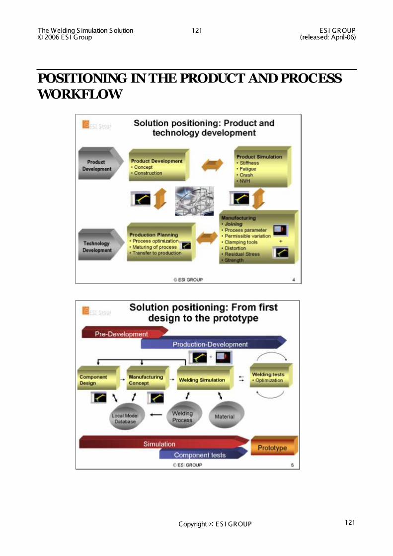
POSITIONING IN THE PRODUCT AND PROCESS WORKFLOW
ESI GROUP 122 The Welding S imulation Solution (released: April-06) © 2006 ES I Group
Copyright ES I GROUP 122
SYSWELD AND PAM-ASSEMBLY - SIMULATION SOLUTION FOR WELDING ASSEMBLY
For very large structures, such as maritime and automotive structures, standard step-by-step welding methodologies are not feasible since these methods require significant computation time and computer memory size.
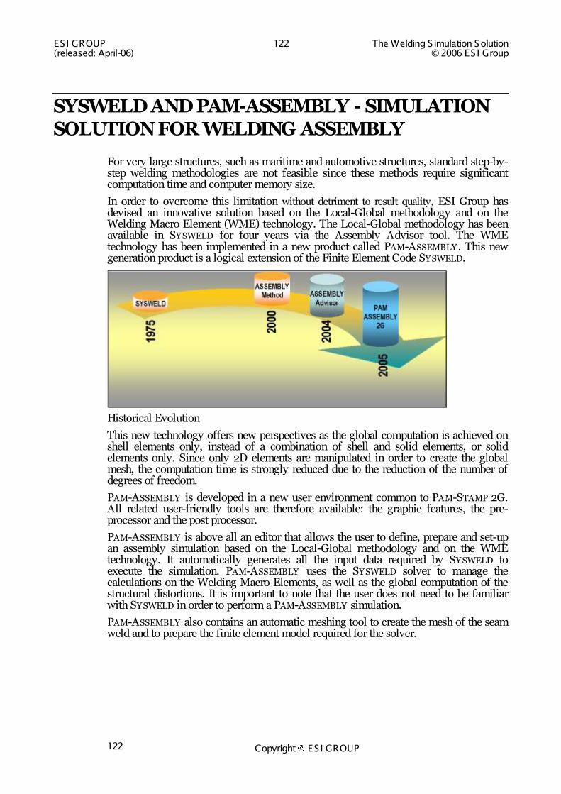
In order to overcome this limitation without detriment to result quality, ESI Group has devised an innovative solution based on the Local-Global methodology and on the Welding Macro Element (WME) technology. The Local-Global methodology has been available in SYSWELD for four years via the Assembly Advisor tool. The WME technology has been implemented in a new product called PAM-ASSEMBLY . This new generation product is a logical extension of the Finite Element Code SYSWELD.
Historical Evolution
This new technology offers new perspectives as the global computation is achieved on shell elements only, instead of a combination of shell and solid elements, or solid elements only. Since only 2D elements are manipulated in order to create the global mesh, the computation time is strongly reduced due to the reduction of the number of degrees of freedom.
PAM-ASSEMBLY is developed in a new user environment common to PAM-STAMP 2G. All related user-friendly tools are therefore available: the graphic features, the pre-processor and the post processor.
PAM-ASSEMBLY is above all an editor that allows the user to define, prepare and set-up an assembly simulation based on the Local-Global methodology and on the WME technology. It automatically generates all the input data required by SYSWELD to execute the simulation. PAM-ASSEMBLY uses the SYSWELD solver to manage the calculations on the Welding Macro Elements, as well as the global computation of the structural distortions. It is important to note that the user does not need to be familiar with SYSWELD in order to perform a PAM-ASSEMBLY simulation.
PAM-ASSEMBLY also contains an automatic meshing tool to create the mesh of the seam weld and to prepare the finite element model required for the solver.
The Welding S imulation Solution 123 ES I GROUP © 2006 ES I Group (released: April-06)
Copyright ES I GROUP 123
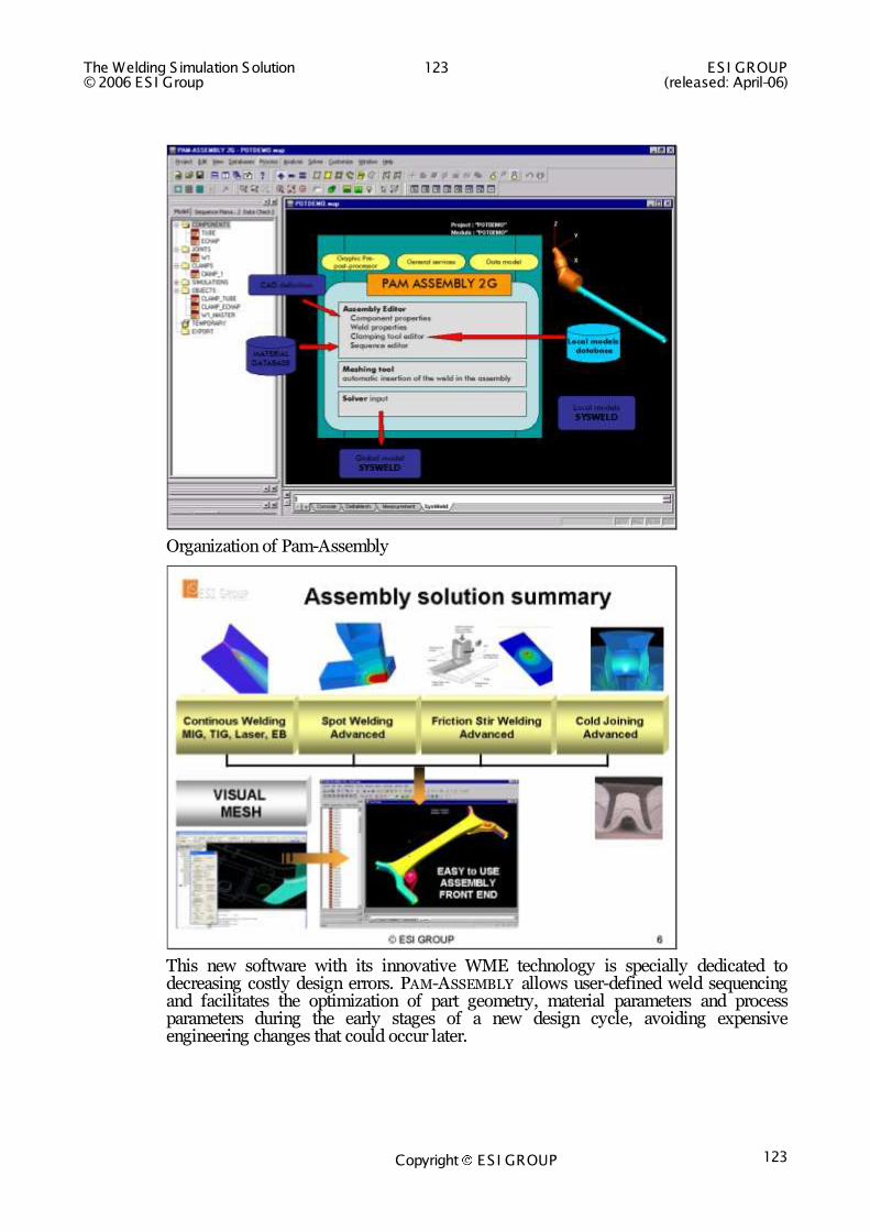
Organization of Pam-Assembly
This new software with its innovative WME technology is specially dedicated to decreasing costly design errors. PAM-ASSEMBLY allows user-defined weld sequencing and facilitates the optimization of part geometry, material parameters and process parameters during the early stages of a new design cycle, avoiding expensive engineering changes that could occur later.
ESI GROUP 124 The Welding S imulation Solution (released: April-06) © 2006 ES I Group
Copyright ES I GROUP 124
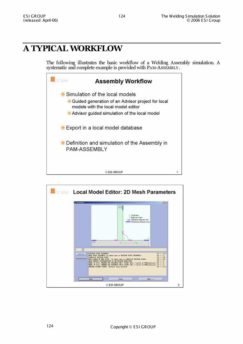
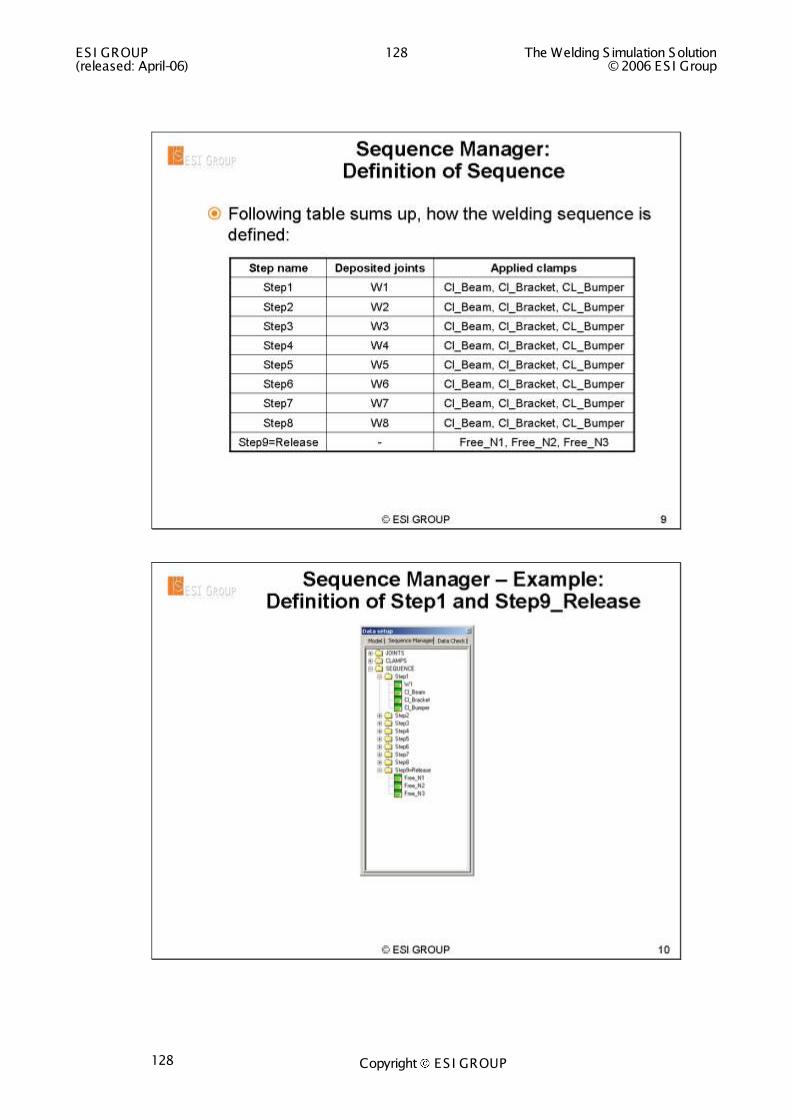
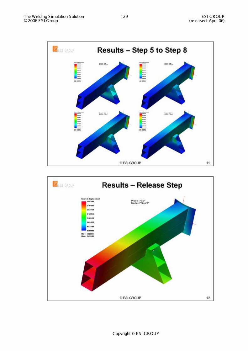
A TYPICAL WORKFLOW
The following illustrates the basic workflow of a Welding Assembly simulation. A systematic and complete example is provided with PAM-ASSEMBLY .

The Welding S imulation Solution 125 ES I GROUP © 2006 ES I Group (released: April-06)
Copyright ES I GROUP

ESI GROUP 126 The Welding S imulation Solution (released: April-06) © 2006 ES I Group
Copyright ES I GROUP 126
The Welding S imulation Solution 127 ES I GROUP © 2006 ES I Group (released: April-06)
Copyright ES I GROUP
ESI GROUP 128 The Welding S imulation Solution (released: April-06) © 2006 ES I Group
Copyright ES I GROUP 128
The Welding S imulation Solution 129 ES I GROUP © 2006 ES I Group (released: April-06)
Copyright ES I GROUP
ESI GROUP 130 The Welding S imulation Solution (released: April-06) © 2006 ES I Group
Copyright ES I GROUP 130
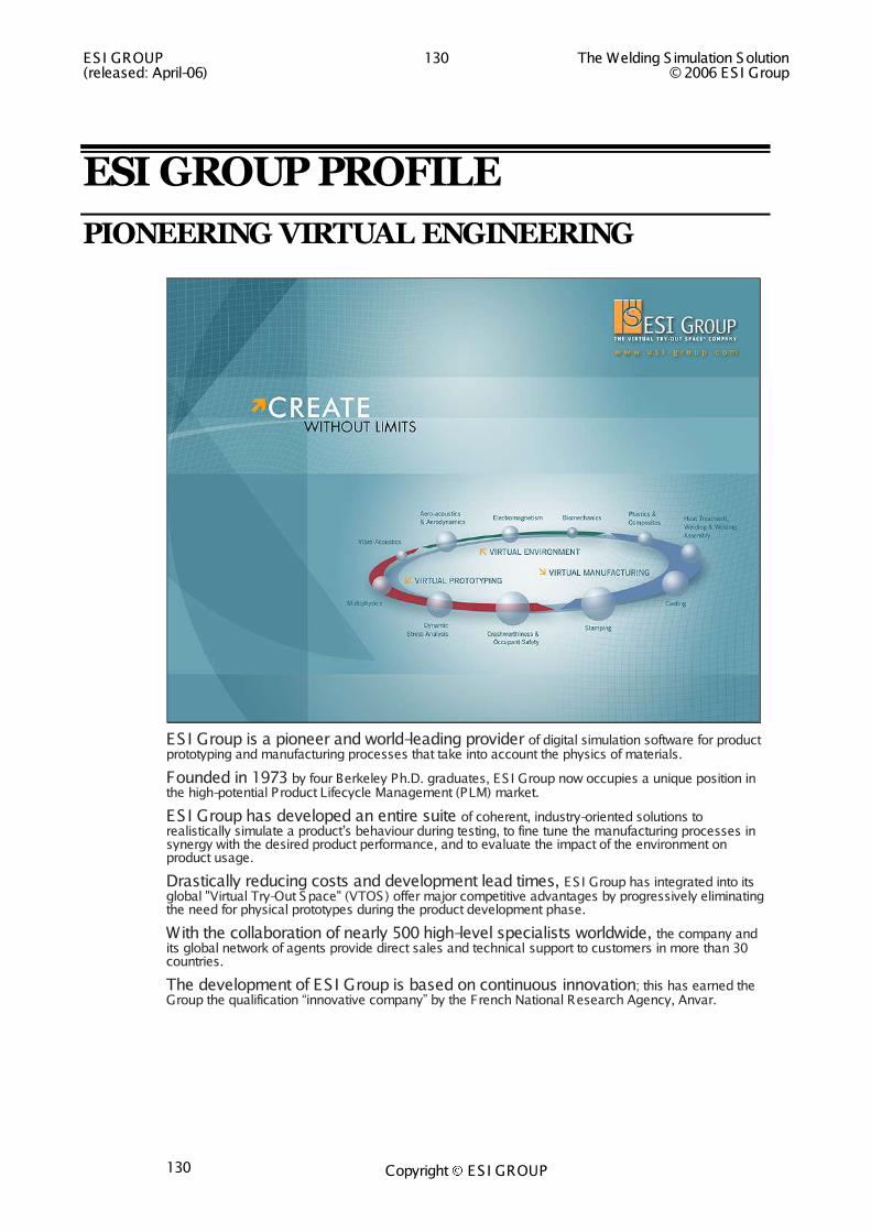
ESI GROUP PROFILE
PIONEERING VIRTUAL ENGINEERING
ESI Group is a pioneer and world-leading provider of digital simulation software for product prototyping and manufacturing processes that take into account the physics of materials.
Founded in 1973 by four Berkeley Ph.D. graduates, ES I Group now occupies a unique position in the high-potential Product Lifecycle Management (PLM) market.
ESI Group has developed an entire suite of coherent, industry-oriented solutions to realistically simulate a product‟s behaviour during testing, to fine tune the manufacturing processes in synergy with the desired product performance, and to evaluate the impact of the environment on product usage.
Drastically reducing costs and development lead times, ES I Group has integrated into its global "Virtual Try-Out Space" (VTOS) offer major competitive advantages by progressively eliminating the need for physical prototypes during the product development phase.
With the collaboration of nearly 500 high-level specialists worldwide, the company and its global network of agents provide direct sales and technical support to customers in more than 30 countries.
The development of ESI Group is based on continuous innovation; this has earned the Group the qualification “innovative company” by the French National Research Agency, Anvar.

The Welding S imulation Solution 131 ES I GROUP © 2006 ES I Group (released: April-06)
Copyright ES I GROUP

ESI GROUP 132 The Welding S imulation Solution (released: April-06) © 2006 ES I Group
Copyright ES I GROUP 132

The Welding S imulation Solution 133 ES I GROUP © 2006 ES I Group (released: April-06)
Copyright ES I GROUP

ESI GROUP 134 The Welding S imulation Solution (released: April-06) © 2006 ES I Group
Copyright ES I GROUP 134
ESI GROUP CONSULTING SERVICES
COMMITTING TO CUSTOMERS
Since more then 30 years, the interest of our clients is the center of our work, whether we are providing software, support or services. Over several decades, our clients have experienced us as experts in our field. We are at any time at your disposal to improve product performance and productivity on the one hand and shortening development times and cost on the other hand.
Consulting services are performed by highly skilled engineers, who, thanks to their in-depth engineering knowledge and their process understanding, are ready to team with you to help you to adopt an integrated innovation approach.
SERVICE OFFER - WELDING
ES I Group offers support of customers and services in all engineering fields involving the following tasks
Development of innovative new welded designs and welding processes
Improvement of the performance and quality of welded products
Cost reduction of all welding fabrication processes
Distortion engineering
These tasks can involve the following welding processes and materials
S ingle pass welding, all kind of processes and materials
Multi-pass welding, all kind of processes and materials
Spot welding, all kind of materials
Friction welding, all kind of materials
Friction stir welding, all kind of metallic materials
You will find a good selection of our service portfolio in the chapters „Applications‟ and „Scientific Applications‟ of this document.
Do not hesitate to contact a subsidiary of ES I Group in your area. You will find the contact data either on the back cover of this document or at www.esi-group.com.
We look forward to working with you soon!

The Welding S imulation Solution 135 ES I GROUP © 2006 ES I Group (released: April-06)
Copyright ES I GROUP
TRAINING COURSES
ESI Group Learning Solutions
2006
ESI GROUP 136 The Welding S imulation Solution (released: April-06) © 2006 ES I Group
Copyright ES I GROUP 136
ESI GROUP LEARNING SOLUTIONS
Reliable, Flexible and Efficient Learning Programs
ES I Group has over 30 years of expertise in software application training courses.
These classes are taught by highly skilled engineers responsible for consulting and support activities, who, thanks to their years of practice and field experience, are fully prepared to answer to the participants‟ needs.
For optimal knowledge transfer, ES I Group honours the following criteria, underlining the effectiveness of its learning programs:
- class sizes are kept small to ensure adequate attention for all attendees, - time is set aside to work on each participant‟s particular demands, - training manuals and a computer are provided for each attendee, - demonstrations and practical exercises are carried out throughout the training, - ...
Participants come away from these classes with a good understanding of all the features of the ES I software of their choice as well as targeted knowledge for immediate application. The courses also provide an excellent forum for ES I Group customers to work with each other and share their experience in digital simulation.
From introductory to advanced or specialized sessions, ES I Group offers an expansive educational program.
In addition to standard courses, ES I Group can set up a dedicated learning program tailored to your needs and knowledge of the software, with flexible training times, content and duration. Customized courses take place either at one of ES I Group‟s worldwide learning facilities or on-site, at your facility.
With decades of training experience and a proven educational methodology, ES I Group software learning courses are the best way to learn about the features and capabilities of the software products you work with daily.
We look forward to working with you soon!

The Welding S imulation Solution 137 ES I GROUP © 2006 ES I Group (released: April-06)
Copyright ES I GROUP
WORLDWIDE LEARNING CENTERS
A broad and expert training network
With field subsidiaries and regional technical support offices spanning four continents, ES I Group provides personalized training services and high-level support to its customers world-wide.
Seoul (South Korea)
Tokyo (Japan)
+ Santa Clara (CA, USA) for ESI CFD Inc.
ESI Group Paris (France)Lyon (France)
Aix (France)
Lausanne, Switzerland
Plzen (Czech Republic)
Seoul (South Korea)
Tokyo (Japan)
+ Santa Clara (CA, USA) for ESI CFD Inc.
ESI Group Paris (France)Lyon (France)
Aix (France)
Lausanne, Switzerland
Seoul (South Korea)
Tokyo (Japan)
+ Santa Clara (CA, USA) for ESI CFD Inc.
ESI Group Paris (France)Lyon (France)
Aix (France)
Lausanne, Switzerland
Seoul (South Korea)
Tokyo (Japan)
+ Santa Clara (CA, USA) for ESI CFD Inc.
ESI Group Paris (France)Lyon (France)
Aix (France)
Lausanne, Switzerland
ESI Group Paris (France)Lyon (France)
Aix (France)
Lausanne, Switzerland
Plzen (Czech Republic)Plzen (Czech Republic)

ESI GROUP 138 The Welding S imulation Solution (released: April-06) © 2006 ES I Group
Copyright ES I GROUP 138
MESHING WELDING APPLICATIONS
Reference: SWD-2005-WM-B
Level: Basic
Duration: 2 days
Audience: Engineers in product development, process design, and manufacturing dealing with welding processes, from Automotive and Heavy Industry
Objectives: Understand how to make the best possible meshes for welding simulation
Prerequisites: Required: engineering background with focus on welding engineering; strong understanding of practical welding.
Helpful: basic knowledge of the Finite E lement method.
Description: The art of meshing welding applications is the major subject of this course. Participants learn to mesh effectively two-dimensional and three-dimensional heat-treated structures.
Course content: - Basics
o Finite E lement recommendations
o Welding recommendations
- Meshing two-dimensional structures o Best practice
- Meshing three-dimensional solid, shell-solid, and shell structures o Best practice
Courtesy: Automobilarbeitskreis
Suggested next course: Welding S imulation Engineering – Getting it Right
(SWD-2005-W-B)

The Welding S imulation Solution 139 ES I GROUP © 2006 ES I Group (released: April-06)
Copyright ES I GROUP
WELDING SIMULATION - GETTING IT RIGHT Reference: SWD-2005-W-B
Level: Basic
Duration: 3 days
Audience: Engineers from product development, process design and manufacturing dealing with welding processes, from Automotive and Heavy Industry.
Objectives: Understand the art of modeling for welding. Then, set up, run and interpret results of a welding simulation.
Prerequisites: Necessary: engineering background with focus on welding engineering and a strong understanding of practical welding.
Helpful: basic knowledge of the Finite E lement method.
Description: The art of modeling for welding is the major subject of this course. The focus is on simplicity and productivity. Participants learn to simulate the heat effects of welding - i.e. distortion and residual stresses - in order to predict and minimize part distortions and improve durability. Improvement of processes and designs based on a deeper understanding of engineering is another focus. This course is for practitioners.
Course content: - Getting started
o Welding a T-J oint with the Welding Wizard; welding solids
o Welding Wizard online help o Key notes o Tips and tricks o Small but nasty o Software architecture o Welding a wheel with the
Welding Wizard; welding of shells
o Welding local models with the Welding Wizard
- Modeling welding heat sources o Energy per unit length of
weld o Heat source fitting tool
- Modeling welding clamping tools - Post-processing o Background of computed results o Multi-physics post-processing
Courtesy: ES I Group - - - - Checklist Welding S imulation o Getting it right:: a summary
- Welding Wizard documentation (*)
- Summary and wrap-up
Suggested next courses: Welding S imulation Engineering – Understanding the Material Background (SWD-2005-WM-A)
Welding Assembly S imulation – Getting it Right (SWD-2005-WA-B)
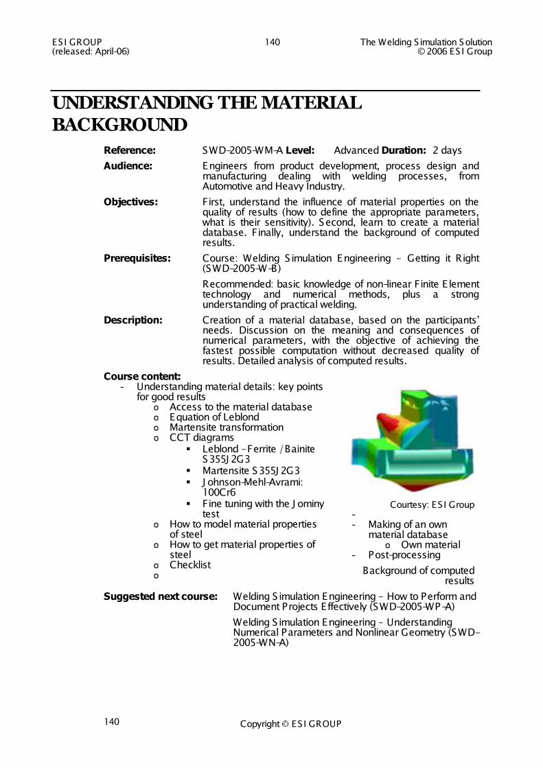
ESI GROUP 140 The Welding S imulation Solution (released: April-06) © 2006 ES I Group
Copyright ES I GROUP 140
UNDERSTANDING THE MATERIAL BACKGROUND
Reference: SWD-2005-WM-A Level: Advanced Duration: 2 days
Audience: Engineers from product development, process design and manufacturing dealing with welding processes, from Automotive and Heavy Industry.
Objectives: First, understand the influence of material properties on the quality of results (how to define the appropriate parameters, what is their sensitivity). Second, learn to create a material database. Finally, understand the background of computed results.
Prerequisites: Course: Welding S imulation Engineering – Getting it Right (SWD-2005-W-B)
Recommended: basic knowledge of non-linear Finite E lement technology and numerical methods, plus a strong understanding of practical welding.
Description: Creation of a material database, based on the participants‟ needs. Discussion on the meaning and consequences of numerical parameters, with the objective of achieving the fastest possible computation without decreased quality of results. Detailed analysis of computed results.
Course content: - Understanding material details: key points
for good results o Access to the material database o Equation of Leblond o Martensite transformation o CCT diagrams
Leblond - Ferrite / Bainite S355J 2G3
Martensite S355J 2G3 J ohnson-Mehl-Avrami:
100Cr6 Fine tuning with the J ominy
test o How to model material properties
of steel o How to get material properties of
steel o Checklist o
Courtesy: ES I Group - - Making of an own
material database o Own material
- Post-processing
Background of computed results
Suggested next course: Welding S imulation Engineering – How to Perform and Document Projects Effectively (SWD-2005-WP-A)
Welding S imulation Engineering – Understanding Numerical Parameters and Nonlinear Geometry (SWD-2005-WN-A)

The Welding S imulation Solution 141 ES I GROUP © 2006 ES I Group (released: April-06)
Copyright ES I GROUP
UNDERSTANDING NUMERICAL PARAMETERS AND NONLINEAR GEOMETRY
Reference: SWD-2005-WN-A Level: Advanced Duration: 1 day
Audience: Advanced designers; simulation engineers; engineers from product development, process design and manufacturing dealing with Welding processes, from Automotive and Heavy Industry.
Objectives: Understand the background of numerical parameter files used in the Welding and Macro Bead Advisor in order to design numerical parameter files for the shortest possible simulation time, whilst keeping good results quality. How to get the best possible simulation models with Finite E lements.
Prerequisites: Course: Welding S imulation Engineering – Getting it Right (SWD-2005-W-B)
Recommended: basic knowledge of non-linear Finite E lement technology and of numerical methods.
Description: This course explains the optimized usage of iterative techniques, linear system of equation solvers and automatic time stepping parameters. Discussion of the meaning and consequences of numerical parameters, with the objective of achieving the fastest possible computation without decreased quality of results. Keys to convergence – the optimization of simulation models – are examined.
Course content: - Understanding iterative techniques
o Initial Newton o Full Newton o Modified Newton o BFGS o Radius of convergence
- Understanding linear system of equation solvers o Skyline solver o Sparse solver o Optimized sparse solver o Iterative solver
- Understanding automatic time stepping - How to choose the best combination of iterative techniques, linear system
of equation solvers and automatic time stepping parameters dedicated to individual problems
- How to design numerical parameter files so that users without FEM background must no longer deal with numerical parameters
- What is nonlinear geometry; when to choose a simulation option for nonlinear geometry
Suggested next course: Welding S imulation Engineering – How to Perform and Document Projects Effectively (SWD-2005-WP-A)
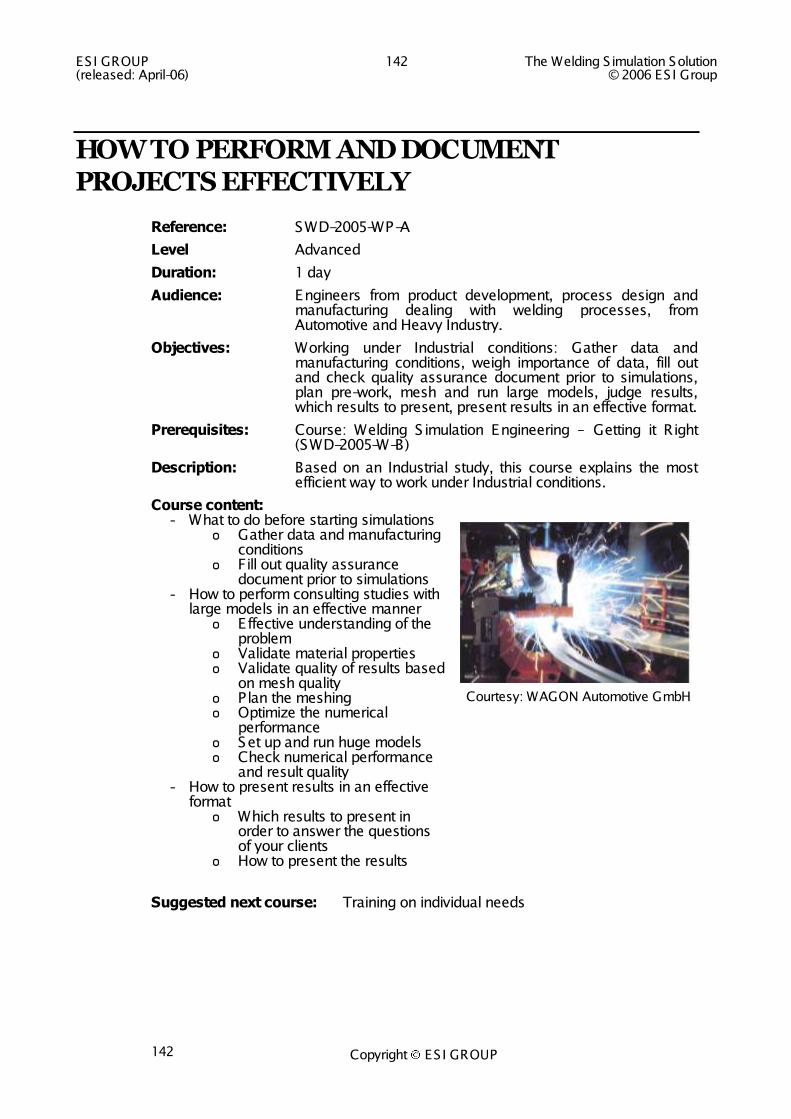
ESI GROUP 142 The Welding S imulation Solution (released: April-06) © 2006 ES I Group
Copyright ES I GROUP 142
HOW TO PERFORM AND DOCUMENT PROJECTS EFFECTIVELY
Reference: SWD-2005-WP-A
Level Advanced
Duration: 1 day
Audience: Engineers from product development, process design and manufacturing dealing with welding processes, from Automotive and Heavy Industry.
Objectives: Working under Industrial conditions: Gather data and manufacturing conditions, weigh importance of data, fill out and check quality assurance document prior to simulations, plan pre-work, mesh and run large models, judge results, which results to present, present results in an effective format.
Prerequisites: Course: Welding S imulation Engineering – Getting it Right (SWD-2005-W-B)
Description: Based on an Industrial study, this course explains the most efficient way to work under Industrial conditions.
Course content: - What to do before starting simulations
o Gather data and manufacturing conditions
o Fill out quality assurance document prior to simulations
- How to perform consulting studies with large models in an effective manner o E ffective understanding of the
problem o Validate material properties o Validate quality of results based
on mesh quality o P lan the meshing o Optimize the numerical
performance o Set up and run huge models o Check numerical performance
and result quality - How to present results in an effective
format o Which results to present in
order to answer the questions of your clients
o How to present the results
Courtesy: WAGON Automotive GmbH
Suggested next course: Training on individual needs

The Welding S imulation Solution 143 ES I GROUP © 2006 ES I Group (released: April-06)
Copyright ES I GROUP
WELDING ASSEMBLY SIMULATION
Reference: SWD-2005-WA-B
Level: Basic
Duration: 2 days
Audience: Automotive and industry engineers involved in the Welding process
Objectives: Learn to perform Welding Assembly S imulations for large components, which cannot be simulated with transient welding in a reasonable time range.
Prerequisites: Course: Welding S imulation Engineering – Getting it Right (SWD-2005-W-B). Explicitly no knowledge in non-linear Finite E lement Analysis is required.
Description: Participants first learn to understand advanced welding assembly simulation methods, and then to set up and run a Welding Assembly simulation. This course is for practitioners.
Course content: - Generation of standard local
models using the local model editor; T, Butt and Overlapp
- Generation of individual local models
- S imulation of the Welding Assembly on selected structures
- Getting it right: Checklist
Welding Assembly of a typical chassis component. Courtesy Renault
Please contact your nearest ESI office for further information and to register for this course (see back cover).
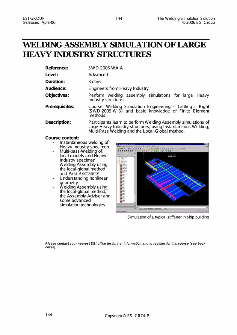
ESI GROUP 144 The Welding S imulation Solution (released: April-06) © 2006 ES I Group
Copyright ES I GROUP 144
WELDING ASSEMBLY SIMULATION OF LARGE HEAVY INDUSTRY STRUCTURES
Reference: SWD-2005-WA-A
Level: Advanced
Duration: 3 days
Audience: Engineers from Heavy Industry
Objectives: Perform welding assembly simulations for large Heavy Industry structures.
Prerequisites: Course: Welding S imulation Engineering – Getting it Right (SWD-2005-W-B) and basic knowledge of Finite E lement methods
Description: Participants learn to perform Welding Assembly simulations of large Heavy Industry structures, using Instantaneous Welding, Multi-Pass Welding and the Local-Global method.
Course content: - Instantaneous welding of
Heavy Industry specimen - Multi-pass-Welding of
local models and Heavy Industry specimen
- Welding Assembly using the local-global method and PAM-ASSEMBLY
- Understanding nonlinear geometry
- Welding Assembly using the local-global method, the Assembly Advisor and some advanced simulation technologies
Simulation of a typical stiffener in ship building
Please contact your nearest ESI office for further information and to register for this course (see back cover).

The Welding S imulation Solution 145 ES I GROUP © 2006 ES I Group (released: April-06)
Copyright ES I GROUP
STAMPING AND WELDING SIMULATION COUPLING
Reference: SWD-2005-WS-A
Level: Advanced
Duration: 2 days
Audience: Automotive and Industry engineers involved in Welding manufacturing and planning.
Objectives: Learn to perform Welding Assembly simulations including results from a PAM-STAMP 2G simulation.
Prerequisites: Courses: Welding S imulation Engineering – Getting it Right (SWD-2005-W-B) and Basic PAM-STAMP 2G.
Solid knowledge of Finite E lements methods
Description: Participants learn to couple stamping-welding and welding-stamping simulations. In case of shell-only models, manufacturing simulation results are prepared for post simulation with general purpose FEM programs or crash simulation using PAM-CRASH.
This course is for advanced analysts.
Course content: - Coupling stamping and
welding simulation using the local-global method
- Coupling stamping and welding simulation using the transient welding method, for shell-solid and shell only structures
- Coupling welding and stamping simulation for the purpose of welding stamped tailored blanks
- Getting it right: Checklist
Preparation of the part in PAM-STAMP 2G
Please contact your nearest ESI office for further information and to register for this course (see back cover).
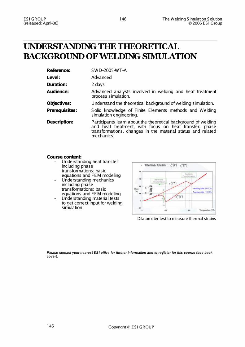
ESI GROUP 146 The Welding S imulation Solution (released: April-06) © 2006 ES I Group
Copyright ES I GROUP 146
UNDERSTANDING THE THEORETICAL BACKGROUND OF WELDING SIMULATION
Reference: SWD-2005-WT-A
Level: Advanced
Duration: 2 days
Audience: Advanced analysts involved in welding and heat treatment process simulation.
Objectives: Understand the theoretical background of welding simulation.
Prerequisites: Solid knowledge of Finite E lements methods and Welding simulation engineering.
Description: Participants learn about the theoretical background of welding and heat treatment, with focus on heat transfer, phase transformations, changes in the material status and related mechanics.
Course content: - Understanding heat transfer
including phase transformations: basic equations and FEM modeling
- Understanding mechanics including phase transformations: basic equations and FEM modeling
- Understanding material tests to get correct input for welding simulation
Dilatometer test to measure thermal strains
Please contact your nearest ESI office for further information and to register for this course (see back cover).

Copyright ES I GROUP
Insert the back cover image in this header, then position and resize it !


![ESI[tronic] Onlineupdate - Bosch Globalupm.bosch.com/update/fahrzeuglistenEU/ezu_2016_1_01.pdf · ESI[tronic] Onlineupdate ... Vehicle Brand System Group System Systemversion](https://img.pdfslide.us/doc/110x75/5aa09a4a7f8b9a67178e76bd/esitronic-onlineupdate-bosch-tronic-onlineupdate-vehicle-brand-system-group.jpg)