Embed Size (px)
Citation preview
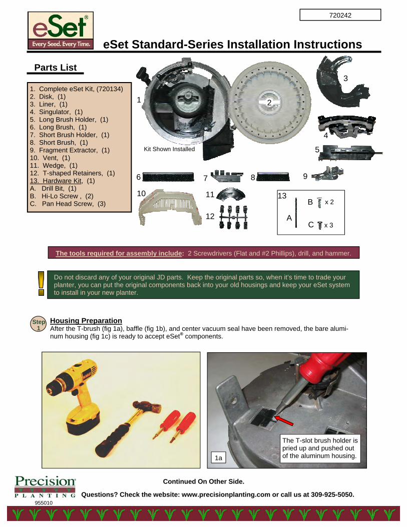
eSet Standard-Series Installation Instructions
955010 Questions? Check the website: www.precisionplanting.com or call us at 309-925-5050.
720242
Housing Preparation After the T-brush (fig 1a), baffle (fig 1b), and center vacuum seal have been removed, the bare alumi-num housing (fig 1c) is ready to accept eSet® components.
Continued On Other Side.
The tools required for assembly include: 2 Screwdrivers (Flat and #2 Phillips), drill, and hammer.
Step 1
Do not discard any of your original JD parts. Keep the original parts so, when it’s time to trade your planter, you can put the original components back into your old housings and keep your eSet system to install in your new planter.
Kit Shown Installed
1 2
9
4
5
6 7 8
1. Complete eSet Kit, (720134) 2. Disk, (1) 3. Liner, (1) 4. Singulator, (1) 5. Long Brush Holder, (1) 6. Long Brush, (1) 7. Short Brush Holder, (1) 8. Short Brush, (1) 9. Fragment Extractor, (1) 10. Vent, (1) 11. Wedge, (1) 12. T-shaped Retainers, (1) 13. Hardware Kit, (1) A. Drill Bit, (1) B. Hi-Lo Screw , (2) C. Pan Head Screw, (3)
The T-slot brush holder is pried up and pushed out of the aluminum housing. 1a
10
3 Parts List
11
12
13
x 3
x 2
A
B
C
Installation Instructions Continued
Questions? Check the website: www.precisionplanting.com or call us at 309-925-5050.
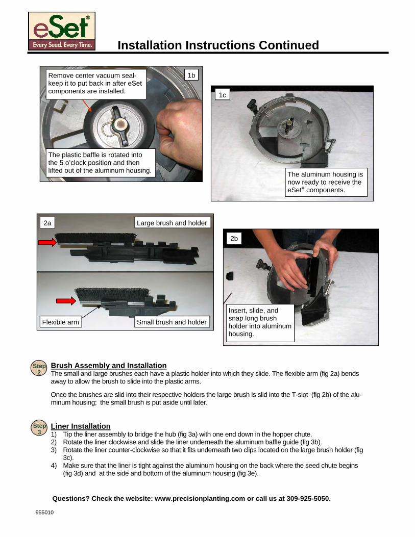
Brush Assembly and Installation The small and large brushes each have a plastic holder into which they slide. The flexible arm (fig 2a) bends away to allow the brush to slide into the plastic arms. Once the brushes are slid into their respective holders the large brush is slid into the T-slot (fig 2b) of the alu-minum housing; the small brush is put aside until later.
Step 2
Liner Installation 1) Tip the liner assembly to bridge the hub (fig 3a) with one end down in the hopper chute. 2) Rotate the liner clockwise and slide the liner underneath the aluminum baffle guide (fig 3b). 3) Rotate the liner counter-clockwise so that it fits underneath two clips located on the large brush holder (fig
3c). 4) Make sure that the liner is tight against the aluminum housing on the back where the seed chute begins
(fig 3d) and at the side and bottom of the aluminum housing (fig 3e).
Step 3
The aluminum housing is now ready to receive the eSet® components.
1c
The plastic baffle is rotated into the 5 o’clock position and then lifted out of the aluminum housing.
1b Remove center vacuum seal- keep it to put back in after eSet components are installed.
Insert, slide, and snap long brush holder into aluminum housing.
2b
Large brush and holder
Small brush and holder
2a
Flexible arm
955010
Installation Instructions Continued
Questions? Check the website: www.precisionplanting.com or call us at 309-925-5050.
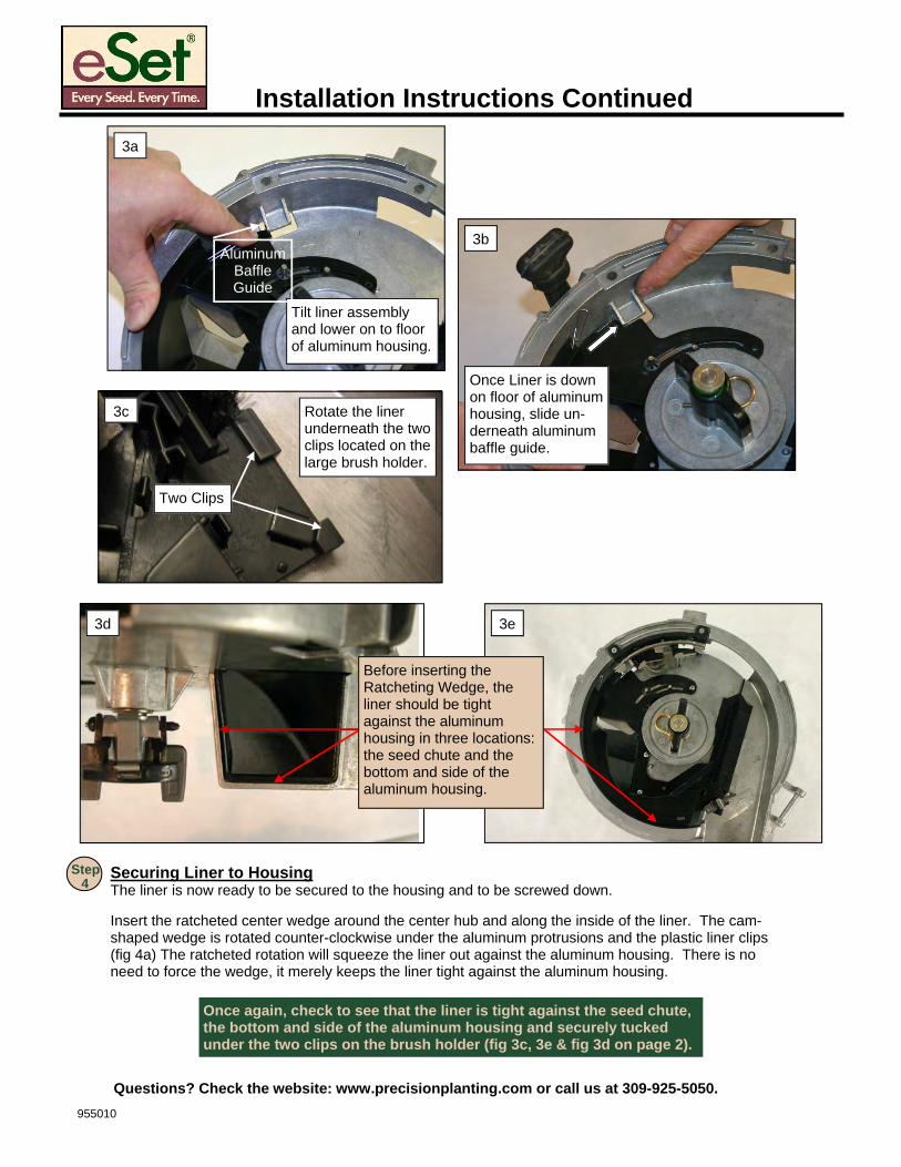
Securing Liner to Housing The liner is now ready to be secured to the housing and to be screwed down. Insert the ratcheted center wedge around the center hub and along the inside of the liner. The cam-shaped wedge is rotated counter-clockwise under the aluminum protrusions and the plastic liner clips (fig 4a) The ratcheted rotation will squeeze the liner out against the aluminum housing. There is no need to force the wedge, it merely keeps the liner tight against the aluminum housing.
Step 4
Tilt liner assembly and lower on to floor of aluminum housing.
Aluminum Baffle Guide
3a
Rotate the liner underneath the two clips located on the large brush holder.
3c
Two Clips
Once Liner is down on floor of aluminum housing, slide un-derneath aluminum baffle guide.
3b
3d 3e
Before inserting the Ratcheting Wedge, the liner should be tight against the aluminum housing in three locations: the seed chute and the bottom and side of the aluminum housing.
Once again, check to see that the liner is tight against the seed chute, the bottom and side of the aluminum housing and securely tucked under the two clips on the brush holder (fig 3c, 3e & fig 3d on page 2).
955010
Installation Instructions Continued
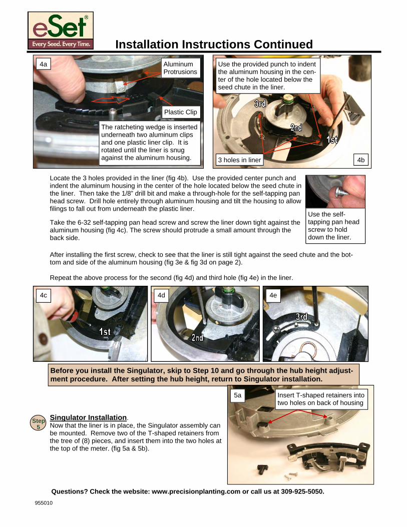
Locate the 3 holes provided in the liner (fig 4b). Use the provided center punch and indent the aluminum housing in the center of the hole located below the seed chute in the liner. Then take the 1/8” drill bit and make a through-hole for the self-tapping pan head screw. Drill hole entirely through aluminum housing and tilt the housing to allow filings to fall out from underneath the plastic liner. Take the 6-32 self-tapping pan head screw and screw the liner down tight against the aluminum housing (fig 4c). The screw should protrude a small amount through the back side.
Singulator Installation. Now that the liner is in place, the Singulator assembly can be mounted. Remove two of the T-shaped retainers from the tree of (8) pieces, and insert them into the two holes at the top of the meter. (fig 5a & 5b).
Step 5
The ratcheting wedge is inserted underneath two aluminum clips and one plastic liner clip. It is rotated until the liner is snug against the aluminum housing.
Plastic Clip
Aluminum Protrusions
4a
3 holes in liner
Use the provided punch to indent the aluminum housing in the cen-ter of the hole located below the seed chute in the liner.
4b
Use the self-tapping pan head screw to hold down the liner.
4c 4d 4e
After installing the first screw, check to see that the liner is still tight against the seed chute and the bot-tom and side of the aluminum housing (fig 3e & fig 3d on page 2).
Repeat the above process for the second (fig 4d) and third hole (fig 4e) in the liner.
Before you install the Singulator, skip to Step 10 and go through the hub height adjust-ment procedure. After setting the hub height, return to Singulator installation.
5a Insert T-shaped retainers into two holes on back of housing
955010
Questions? Check the website: www.precisionplanting.com or call us at 309-925-5050.
Installation Instructions Continued
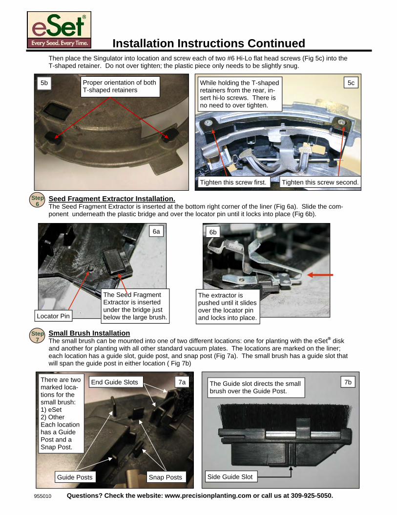
Seed Fragment Extractor Installation. The Seed Fragment Extractor is inserted at the bottom right corner of the liner (Fig 6a). Slide the com-ponent underneath the plastic bridge and over the locator pin until it locks into place (Fig 6b).
Step 6
Small Brush Installation The small brush can be mounted into one of two different locations: one for planting with the eSet® disk and another for planting with all other standard vacuum plates. The locations are marked on the liner; each location has a guide slot, guide post, and snap post (Fig 7a). The small brush has a guide slot that will span the guide post in either location ( Fig 7b)
Step 7
Then place the Singulator into location and screw each of two #6 Hi-Lo flat head screws (Fig 5c) into the T-shaped retainer. Do not over tighten; the plastic piece only needs to be slightly snug.
Proper orientation of both T-shaped retainers
5b
Tighten this screw second. Tighten this screw first.
While holding the T-shaped retainers from the rear, in-sert hi-lo screws. There is no need to over tighten.
5c
The extractor is pushed until it slides over the locator pin and locks into place.
6b
The Seed Fragment Extractor is inserted under the bridge just below the large brush. Locator Pin
6a
The Guide slot directs the small brush over the Guide Post.
Side Guide Slot
7b There are two marked loca-tions for the small brush: 1) eSet 2) Other Each location has a Guide Post and a Snap Post.
7a
Guide Posts Snap Posts
End Guide Slots
955010 Questions? Check the website: www.precisionplanting.com or call us at 309-925-5050.
Installation Instructions Continued
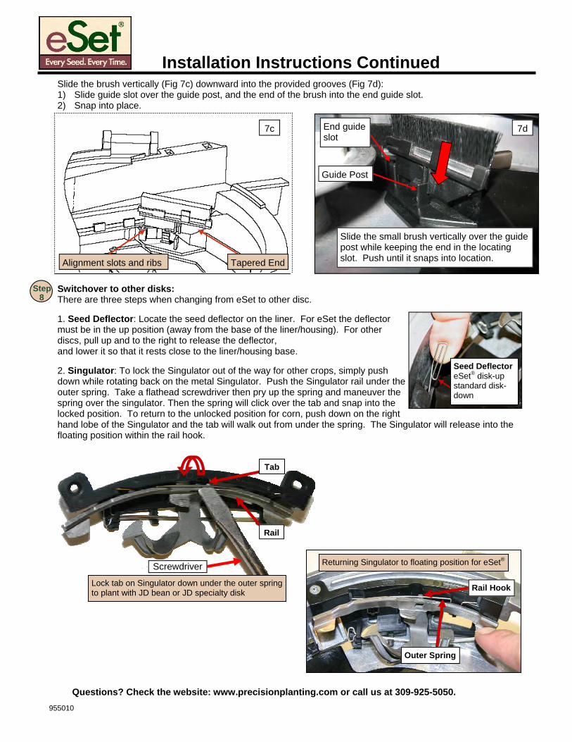
Slide the brush vertically (Fig 7c) downward into the provided grooves (Fig 7d): 1) Slide guide slot over the guide post, and the end of the brush into the end guide slot. 2) Snap into place.
Switchover to other disks: There are three steps when changing from eSet to other disc. 1. Seed Deflector: Locate the seed deflector on the liner. For eSet the deflector must be in the up position (away from the base of the liner/housing). For other discs, pull up and to the right to release the deflector, and lower it so that it rests close to the liner/housing base. 2. Singulator: To lock the Singulator out of the way for other crops, simply push down while rotating back on the metal Singulator. Push the Singulator rail under the outer spring. Take a flathead screwdriver then pry up the spring and maneuver the spring over the singulator. Then the spring will click over the tab and snap into the locked position. To return to the unlocked position for corn, push down on the right hand lobe of the Singulator and the tab will walk out from under the spring. The Singulator will release into the floating position within the rail hook.
Slide the small brush vertically over the guide post while keeping the end in the locating slot. Push until it snaps into location.
Guide Post
7d
Alignment slots and ribs
7c
Tapered End
Returning Singulator to floating position for eSet®
Outer Spring
Rail Hook
Rail
Seed Deflector eSet® disk-up standard disk-down
End guide slot
Step 8
Tab
Screwdriver
Lock tab on Singulator down under the outer spring to plant with JD bean or JD specialty disk
955010
Questions? Check the website: www.precisionplanting.com or call us at 309-925-5050.
Installation Instructions Continued
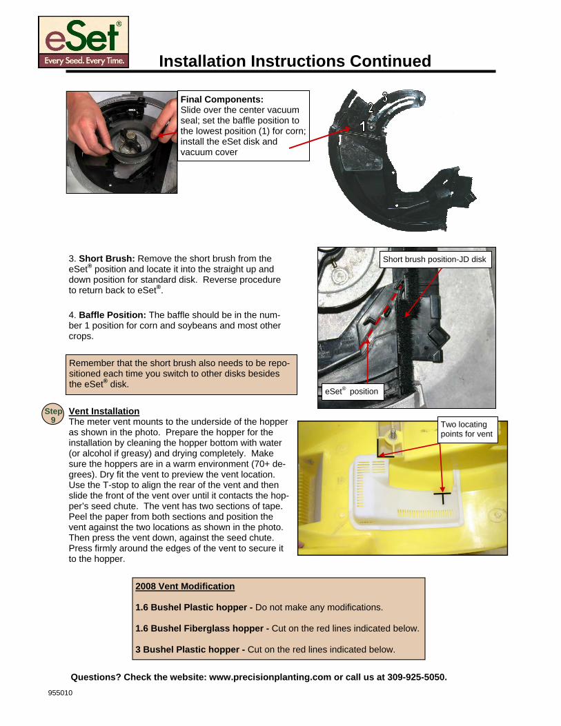
Remember that the short brush also needs to be repo-sitioned each time you switch to other disks besides the eSet® disk.
Short brush position-JD disk
eSet® position
3. Short Brush: Remove the short brush from the eSet® position and locate it into the straight up and down position for standard disk. Reverse procedure to return back to eSet®.
Vent Installation The meter vent mounts to the underside of the hopper as shown in the photo. Prepare the hopper for the installation by cleaning the hopper bottom with water (or alcohol if greasy) and drying completely. Make sure the hoppers are in a warm environment (70+ de-grees). Dry fit the vent to preview the vent location. Use the T-stop to align the rear of the vent and then slide the front of the vent over until it contacts the hop-per’s seed chute. The vent has two sections of tape. Peel the paper from both sections and position the vent against the two locations as shown in the photo. Then press the vent down, against the seed chute. Press firmly around the edges of the vent to secure it to the hopper.
Two locating points for vent
Step 9
4. Baffle Position: The baffle should be in the num-ber 1 position for corn and soybeans and most other crops.
2008 Vent Modification 1.6 Bushel Plastic hopper - Do not make any modifications. 1.6 Bushel Fiberglass hopper - Cut on the red lines indicated below. 3 Bushel Plastic hopper - Cut on the red lines indicated below.
Final Components: Slide over the center vacuum seal; set the baffle position to the lowest position (1) for corn; install the eSet disk and vacuum cover
955010
Questions? Check the website: www.precisionplanting.com or call us at 309-925-5050.
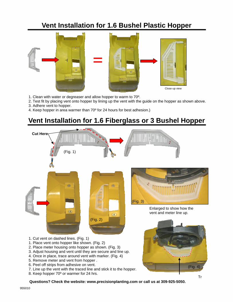
Cut Here
Vent Installation for 1.6 Fiberglass or 3 Bushel Hopper
Tr
1. Cut vent on dashed lines. (Fig. 1) 1. Place vent onto hopper like shown. (Fig. 2) 2. Place meter housing onto hopper as shown. (Fig. 3) 3. Adjust housing and vent until they are secure and line up. 4. Once in place, trace around vent with marker. (Fig. 4) 5. Remove meter and vent from hopper . 6. Peel off strips from adhesive on vent. 7. Line up the vent with the traced line and stick it to the hopper. 8. Keep hopper 70º or warmer for 24 hrs.
=
Vent Installation for 1.6 Bushel Plastic Hopper
1. Clean with water or degreaser and allow hopper to warm to 70º. 2. Test fit by placing vent onto hopper by lining up the vent with the guide on the hopper as shown above. 3. Adhere vent to hopper. 4. Keep hopper in area warmer than 70º for 24 hours for best adhesion.)
Close-up view
Enlarged to show how the vent and meter line up.
(Fig. 2)
(Fig. 1)
(Fig. 3)
(Fig. 4)
955010
Questions? Check the website: www.precisionplanting.com or call us at 309-925-5050.
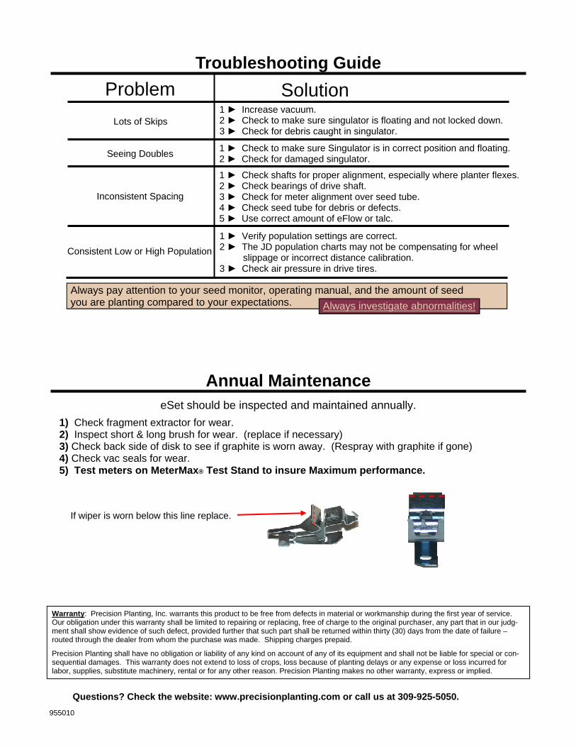
Inspect Vacuum Seal The seal should not have any wavy sections and the height of the seal should be very uniform around the entire circumference. The section of the seal where the seed is released should be free from wear grooves. If this area is grooved, replace the seal. Note: John Deere made a design change to the seal in recent years that makes the seal more stiff. They recommend that the soft and stiff seals not be intermixed within the same planter to ensure uniform vacuum pressure from row to row. Precision Planting has replacement seals available in a pack of 2 pcs (order part number 720076 for two outer seals and 720077 for two hub seals)
Seal should be uniform in height around circum-ference
Seed Release Area: Seal should be straight with no wear grooves
Installation Instructions Continued
Step 11
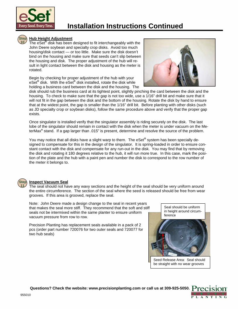
Hub Height Adjustment The eSet® disk has been designed to fit interchangeably with the John Deere soybean and specialty crop disks. Avoid too much housing/disk contact — or too little. Make sure the disk doesn’t bind on the housing and make sure that seeds can’t slip between the housing and disk. The proper adjustment of the hub will re-sult in light contact between the disk and housing as the meter is rotated. Begin by checking for proper adjustment of the hub with your eSet® disk. With the eSet® disk installed, rotate the disk while holding a business card between the disk and the housing. The disk should rub the business card at its tightest point, slightly pinching the card between the disk and the housing. To check to make sure that the gap is not too wide, use a 1/16” drill bit and make sure that it will not fit in the gap between the disk and the bottom of the housing. Rotate the disk by hand to ensure that at the widest point, the gap is smaller than the 1/16” drill bit. Before planting with other disks (such as JD specialty crop or soybean disks), follow the same procedure above and verify that the proper gap exists. Once singulator is installed verify that the singulator assembly is riding securely on the disk. The last lobe of the singulator should remain in contact with the disk when the meter is under vacuum on the Me-terMax® stand. If a gap larger than .015” is present, determine and resolve the source of the problem. You may notice that all disks have a slight warp to them. The eSet® system has been specially de-signed to compensate for this in the design of the singulator. It is spring-loaded in order to ensure con-stant contact with the disk and compensate for any run-out in the disk. You may find that by removing the disk and rotating it 180 degrees relative to the hub, it will run more true. In this case, mark the posi-tion of the plate and the hub with a paint pen and number the disk to correspond to the row number of the meter it belongs to.
Step 10
955010
Questions? Check the website: www.precisionplanting.com or call us at 309-925-5050.
Warranty: Precision Planting, Inc. warrants this product to be free from defects in material or workmanship during the first year of service. Our obligation under this warranty shall be limited to repairing or replacing, free of charge to the original purchaser, any part that in our judg-ment shall show evidence of such defect, provided further that such part shall be returned within thirty (30) days from the date of failure – routed through the dealer from whom the purchase was made. Shipping charges prepaid. Precision Planting shall have no obligation or liability of any kind on account of any of its equipment and shall not be liable for special or con-sequential damages. This warranty does not extend to loss of crops, loss because of planting delays or any expense or loss incurred for labor, supplies, substitute machinery, rental or for any other reason. Precision Planting makes no other warranty, express or implied.
Troubleshooting Guide
Solution Problem Lots of Skips
1 ► Increase vacuum. 2 ► Check to make sure singulator is floating and not locked down. 3 ► Check for debris caught in singulator.
Seeing Doubles 1 ► Check to make sure Singulator is in correct position and floating. 2 ► Check for damaged singulator.
1 ► Check shafts for proper alignment, especially where planter flexes. 2 ► Check bearings of drive shaft. 3 ► Check for meter alignment over seed tube. 4 ► Check seed tube for debris or defects. 5 ► Use correct amount of eFlow or talc.
Inconsistent Spacing
Always pay attention to your seed monitor, operating manual, and the amount of seed you are planting compared to your expectations. Always investigate abnormalities!
Consistent Low or High Population 1 ► Verify population settings are correct. 2 ► The JD population charts may not be compensating for wheel slippage or incorrect distance calibration. 3 ► Check air pressure in drive tires.
Annual Maintenance
1) Check fragment extractor for wear. 2) Inspect short & long brush for wear. (replace if necessary) 3) Check back side of disk to see if graphite is worn away. (Respray with graphite if gone) 4) Check vac seals for wear. 5) Test meters on MeterMax® Test Stand to insure Maximum performance.
eSet should be inspected and maintained annually.
If wiper is worn below this line replace.
955010
Questions? Check the website: www.precisionplanting.com or call us at 309-925-5050.
eSet® OPERATING GUIDELINES
Thank you for placing your confidence in Precision Planting’s eSet®. While this revolutionary system of-fers unparalleled operating simplicity, there are some guidelines to keep in mind for optimum perform-ance.
Vacuum Setting:
Baffle Position:
Lubricant: As with all vacuum planters, eSet® works best with lubricated seed. Follow the general recommenda-tion below and adjust as necessary to prevent excess accumulation of talc in the meter.
Disk Changes: The eSet® disk is designed especially for planting corn. At this time, specialty crops should be planted with the standard John Deere disks you previously used. For limited amounts of sweetcorn, the eSet® disk will plant fine. (If planting production fields of sweetcorn, contact Precision Planting for a special disk.) When plant-ing specialty crops or using celled disks, verify that seeds are not interfering with the singulator assembly and re-move singulator assembly if necessary. There are three parts that need to be adjusted when you are switching from the eSet® disk to a JD disk. The Short Brush, the Seed Deflector and the Singulator. All three are described below.
Bag Weight Vacuum Level Less than 60 lbs (>1350 seeds/lb) 15”
Greater than 60 lbs (<1350 seeds/lb) 18”
Crop Baffle Position Soybeans 1 or 2
Corn 1
Sweetcorn 2
Large specialty crops 2
JD celled disks 2
Seed characteristics Application rate Type of Lubricant Less than 60 lbs (>1350 seeds/lb) 1/4 Cup per Unit eFlow (80% Talc, 20% graphite)
Greater than 60 lbs (<1350 seeds/lb) 1/8 Cup per Unit eFlow (80% Talc, 20% graphite)
Humid planting conditions Increase rate as necessary eFlow (80% Talc, 20% graphite)
Treated seed (Poncho/Cruiser) Increase rate as necessary eFlow (80% Talc, 20% graphite)
PLEASE DETACH THIS FORM AND KEEP FOR QUICK REFERENCE
The baffle regulates the amount of seed entering the meter. Numbers molded to the left of the metal post designate the position.
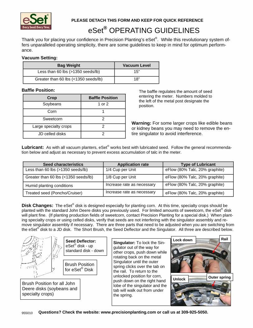
Singulator: To lock the Sin-gulator out of the way for other crops, push down while rotating back on the metal Singulator until the outer spring clicks over the tab on the rail. To return to the unlocked position for corn, push down on the right hand lobe of the singulator and the tab will walk out from under the spring.
Brush Position for all John Deere disks (soybeans and specialty crops)
Brush Position for eSet® Disk
Seed Deflector: eSet® disk - up standard disk - down
Rail Lock down
Unlock Outer spring
Warning: For some larger crops like edible beans or kidney beans you may need to remove the en-tire singulator to avoid interference.
955010 Questions? Check the website: www.precisionplanting.com or call us at 309-925-5050.