Embed Size (px)
Citation preview
ESE 558: DIGITAL IMAGE PROCESSING
WRITTEN REPORT
TRANSMISSION OF JPEG2000 IMAGES OVER NOISY CHANNELS
SUBMITTED BY
TEJY JACOB THOMAS
ID# 105237545
2
TRANSMISSION OF JPEG2000 IMAGES OVER NOISY CHANNELS
Introduction
JPEG2000, or jpeg2k, is the new standard for digital imaging and compression. As
digital imagery becomes more commonplace and has higher quality, there is the need to
manipulate more and more data. Thus, image compression must not only reduce the
necessary storage and bandwidth requirements, but also allow extraction for editing,
processing, and targeting particular devices and applications. The JPEG2000 image
compression system allows extraction of different resolutions, pixel fidelities, regions of
interest, components, and more, all from a single compressed bit stream. This allows an
application to manipulate or transmit only the essential information for any target device
from any JPEG2000 compressed source image. JPEG2000 has a long list of features, a
subset of which is:
• State-of-the-art low bit-rate compression performance
• Progressive transmission by quality, resolution, component, or spatial locality
• Lossy and lossless compression (with lossless decompression available naturally
through all types of progression)
• Random (spatial) access to the bit stream
• Pan and zoom (with decompression of only a subset of the compressed data)
• Compressed domain processing (e.g., rotation and cropping)
• Region of interest coding by progression
• Limited memory implementations.
The demand for multimedia communications is increasing every year, spurred on by
the deployment of emerging compression and communication technologies. In particular,
the interest in communications of multimedia information, such as data, voice, images
and video over wireless channels has increased considerably during the last few years.
Wireless devices are expected to efficiently transmit large amounts of multimedia data
and image transmission is one of the desired features. Multimedia compression is central
to achieving efficient use of storage and bandwidth available. The ISO MPEG and JPEG
groups along with ITU have developed standards to address the compression needs of
audio, video and systems. JPEG2000 offers unprecedented levels of performance, but at a
computational cost that favors FPGA technology over traditional processor-based
solutions. JPEG2000 is instrumental in developing harmonized methods for multimedia
content representation. The importance of the field is demonstrated through the massive
deployment of interactive multimedia services materialized through Internet and other
advanced communications systems like second generation mobile systems and satellite
communications. Compression is a key issue for efficient use and continued fast growth
in this area. JPEG2000 will provide software solutions for high quality low rate still
images for these fields.
Since wireless channels present bandwidth constraints, compression techniques are
used to reduce the amount of information to be transmitted. Moreover, if transmission
errors are present, the transmitted information can be significantly affected, reducing the
3
probability of correct decoding the information. Therefore, in order to offer a good
quality of service, robust transmission of compressed multimedia data over error prone
channels is crucial. The emerging JPEG2000 still image compression standard has made
a considerable progress to address the issue of communications over error prone
channels. This standard incorporates a set of tools that make the compressed information
more resilient to errors. When dealing with noisy channels these tools have proven to
provide a better performance compared to the well-established JPEG standard.
Nevertheless, the use of the error resilient tools does not guarantee an error free received
image, since residual bit-errors can still affect the compressed information. One way to
reduce or eliminate the effect of error prone channels is the use of forward error
correction (FEC) and automatic repeat request (ARQ). However, the joint use of a FEC-
ARQ technique involves the introduction of additional delay, which is not always
desirable in practical applications. On the other hand, by using only a FEC strategy, the
overall transmission bit-rate increases considerably.
More particularly, we are interested in maximizing the received image quality, in the
presence of random bit errors. Such conditions might be expected in the context of
wireless image transmission. The JPEG2000 standard offers a variety of coding modes
and syntax features, which may be used to provide some degree of protection against
errors. Most notable amongst these are: a) the option to include resync markers in the
code stream; b) the ability to modify the arithmetic codeword segments so as to allow
detection and concealment of errors in individual code-blocks; and c) the ability to
partition the compressed data into independently decodable elements.
Although these techniques help, they are unable to recover lost data. Earlier
Hamming Codes were used to provide unequal error protection for JPEG2000 code-
streams, using the memoryless channel model followed by the proposal to use turbo
codes to protect JPEG2000 code streams. These earlier works do not consider the
problem of optimizing the JPEG2000 coding parameters themselves; nor do they
consider the application of different levels of protection to different quality layers in the
code-stream. The selection of Reed Solomon (RS) codes is motivated by their ability to
offer strong protection without excessive complexity. The use of block codes particularly
simplifies switching between different codes to protect different parts of the code-stream
unequally. In certain applications error resilience is needed in order to ensure operation
under conditions where the bit stream input to the decoder may contain bit errors.
Advantages Of JPEG2000 Over Other Image Standards
JPEG2000 offers numerous advantages over the older JPEG and GIF formats. Good
image quality even at high image compression is a major benefit, as is wavelet-based
compression. Higher image quality for the same file size as JPEGs and 25 to 35 percent
smaller file sizes are other positive advances associated with this technology. JPEG2000
compression technology retains image quality better than the old JPEG. It's also faster
and uses a small amount of data. This new standard is revolutionizing digital imaging.
4
Although GIFs are adequate for simple artwork, they do not handle photographic
images well. GIFs also have a similar problem with value and tonal differences.
JPEG2000 is ideal for photographic images because it reproduces colors and tonal
variations faithfully, unlike the GIF format.
Before JPEG2000, the image standard generally used for photo images was JPEG.
The JPEG image compression system was developed for color and black and white
images. The original intent was to deliver photographic images at a small bit rate, and
overcome the limitations of other compression systems such as GIFs. JPEG soon proved
to have limitations. The compression system is "lossy", meaning that whenever an image
is compressed and decompressed, it loses data. This eventually affects the image quality,
and can distort the picture. Another limitation of JPEG is its inability to handle sharp
edges within the image. The stronger the compression rate, the worse it got.
JPEG2000 was developed to correct the limitations of the JPEG format used in
Internet and other applications. JPEG2000 uses wavelet transforms, complex
mathematical formulas representing image data, to compress images at a high rate with a
small amount of data. This allows higher quality images that can handle sharp edges
better and reduce the amount of lost data from compression. JPEG2000 provides better
rate-distortion performance, for any given rate, than the original JPEG standard.
However, the largest improvements are observed at very high and very low bit rates.
While JPEG provided different methods of generating progressive bit streams, with
JPEG-2000 the progression is simply a matter of the order the compressed bytes are
stored in a file. Furthermore, the progression can be changed, additional quantization can
be done, or a server can respond only with the data desired by a client, all without
decoding the bit stream. Since the Internet is HTML based, high image quality is a
challenge. JPEG2000 was designed in response to the need for high quality; low bit rate
images needed for the Internet and other image applications. Along with new internet
capabilities, JPEG2000 has new features and functions designed for wireless devices,
digital cameras, image scanning and client/server imaging applications.
The JPEG2000 compression standard strives to address a broad range of application
areas and is characterized by 'profile' and 'level' of operation. A profile defines the set of
standard algorithmic capabilities employed in a codec. The level defines a set of
parametric choices made within a particular profile, such as frame size and rate. The
diverse markets served by this standard include digital video broadcast, multimedia over
IP, multimedia over wireless, video surveillance, medical imaging, and digital cinema.
This market spans a wide range of requirements for capture, computation and display.
Many technology companies are now adopting the JPEG2000 compression standard.
Hardware and software solutions for JPEG2000-enabled products such as printers,
scanners, fax machines, digital cameras, PDAs, remote sensors and wireless transmission
devices will soon be commonplace.
5
Wireless Channels
Wireless channels are characterized by their limited bandwidths and high bit error
rates. They require protection to provide the necessary quality of service guarantees for
compressed image data. Two models that exist in developing robust image transmission
are:
• Bit error loss models
• Packet loss models.
Bit error loss models assume random bit errors, occurring at some specified bit error
rate (BER). On the other hand packet loss models assume that the data is partitioned into
either fixed or variable length packets. Commonly it is assumed that lost packets are
detected, and a lost packet does not disrupt the reception of subsequent packets. Such a
model is valid for a wireless channel when Forward Error Correction (FEC) codes are
applied in the transport layer to protect the contents of each packet; when the capabilities
of the FEC codes are exceeded, the packet is considered lost. At present, we restrict our
attention to the bit error models, assuming a memoryless error process. This allows us to
tailor the FEC codes to the properties of the compressed data source that is being
protected.
Image Transmission over Mobile and Wireless Channels
• Transmission delay versus error resilient mode
Transmission of still images over error prone channels is really a matter of deciding
on the tradeoffs between what transmission delay you can accept versus quality of the
received images. As a case we show the transmission delay when transmitting a
compressed image over a mobile data channel with retransmissions versus transmitting
over a non-transparent data channel with residual random bit errors. Retransmission will
guarantee an error free transmission in comparison to the non-transparent channel, which
in general will experience a varying random bit error rate.
Most mobile and wireless systems of today use the ARQ protocol in order to
guarantee an error free transmission of data. In this, when the receiver cannot understand
the received data, for example when the quality of the transmitted image decreases or a
bit error is detected in the bit stream, it demands a retransmission of these data from the
transmitter. As a consequence of this, the number of retransmission increases
dramatically when the channel becomes noisy, resulting in an increase in the transmission
delay, which is equivalent to transmitting the image at a much higher rate.
• Still Images Transmission
In this section we will demonstrate the system for various retransmission rates and
relate this to equivalent random bit error rates and quality considerations. As an example,
consider an image with size 2048 x 2560, and consider that this is compressed to 0.5 bpp.
The number of bits to transmit will be
0:5bpp x (2048 x 2560) = 2621440 bits.
6
For transmission over mobile systems, such as GSM, the information is organized in
bursts. In the example we consider bursts containing 114 bits of data each. Thus, 22996
bursts are needed for transmitting the 2621440 bits. This gives the necessary delay for
transmission of the image as approximately 4 minutes and 30 seconds assuming 9.6 Kbps
data rate for the data channel. Further we need to assume the retransmission rate
(as a percentage of the bursts that need to be retransmitted). For example, assuming 60%,
(p=2/3), retransmission, and considering the value K as the seconds needed for
transmission, the delay is obtained as:
K + K x 0.6 + K x 0.6 x 0.6 + K x 0.6 x 0.6 x 0.6 +… =
X
i
i
K0
)6.0(=
= KK =)6.0!1/1( x 2.5
In general, considering a probability of retransmission as p will result in a delay of:
)!1/1( pK seconds
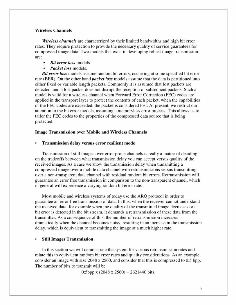
The result shows an exponential behavior of the time delay as a function of the
retransmission rate as shown in the figure below.
From these results, it is clear that noisy channels will result in a significant time
delay. In order to avoid this, the transmission could be done through the non-transparent
channel. For such a transmission, the number of retransmissions is translated to a specific
Bit Error Rate, ber (number of error bits/total number of bits), in every burst. This
relation is showed mathematically below.
First define the Bit Error Ratio. If we designate n as the number of erroneous bits in the
data size L the ber is defined as
ber = n/L
where the following condition must be satisfied
0 · ber · 1:
7
If we now consider the probability of retransmission p, we can define it as
p = (number of retransmissions/total number of transmissions)
From this we can make the following deductions
p = 0; n = 0 ) ber = 0
p =1/2 ; n 2 [1;L] ) ber 2 [1/L; 1]
The last relation is obtained taking into account only one transmission of L for the limits
of the ber.
Continuing,
p = 2/3 ; n 2 [2;L] ) ber 2 [2/L; 1]
p = 3/4 ; n 2 [3;L] ) ber 2 [3/L; 1]
And in general,
p = i/i + 1 ; n 2 [i;L] ) ber 2 [i/L; 1]
The last condition for the obtained ber implies
i/L · 1 ) i · L
and considering
p = i/i + 1 ) i = p/1 ¡ p
then,
p ·L/1 + L
Therefore, we get the next approximation of the relation between p and the ber
ber = ½ 1/L( p/1¡p) if p · L/1+L
= 1 else
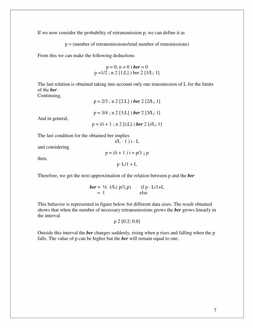
This behavior is represented in figure below for different data sizes. The result obtained
shows that when the number of necessary retransmissions grows the ber grows linearly in
the interval
p 2 [0:2; 0:8]
Outside this interval the ber changes suddenly, rising when p rises and falling when the p
falls. The value of p can be higher but the ber will remain equal to one.
8
Behavior of the ber as a function of the probability of retransmission.
Using the ARQ protocol, one can consider the probability of having to retransmit one
data packet as the probability of having one error within the data packet size L, given as
P(1 error bit in L) = 1 ¡ P(no error) = 1 ¡ (1 ¡ ber)^L
However, this expression does not take into account the total number of necessary
retransmissions that the decoder needs to transmit the data error free to the receiver. To
include this, consider the receiver to ask for a retransmission either if only one bit is
corrupted or, in worst case, the complete L bits are affected by errors. Considering only
one retransmission, i.e., the receiver gets the error free data in the second transmission,
we have the retransmission rate as p = 1=2.
Assuming transmission of L bits in the non transparent channel, we could
alternatively accept a certain degradation of the received information, i.e., a certain ber in
the received bit stream. At least one bit is corrupted because a retransmission is done in
the ARQ scheme, always considering that only L bits are transmitted. For this we obtain
the bit error rate of ber = 1/ L at the receiver. If two retransmissions are necessary, at
least two bits must be wrong, one in the first transmission and another one in the second
transmission. But in case of transmitting in the speech channels only one transmission is
considered. For equating the retransmission rate to the ber, this means that at least two
bits must be wrong in L giving ber = 2/ L.
This gives the behavior of the ber as a function of the probability of retransmission as
shown in the above figure for various packet sizes. The tradeoff for the application will
be to decide whether to use the transparent data channel (with ARQ), with its inherent
delay problems, or translate this time delay to an equivalent ber, knowing that the image
9
decoder is error resilient and will be able to decode the image, but sacrificing slightly in
quality.
Reed-Solomon Codes
Reed-Solomon codes are block-based error correcting codes with a wide range of
applications in digital communications and storage. Reed-Solomon codes are used to
correct errors in many systems including:
• Storage devices (including tape, Compact Disk, DVD, barcodes, etc)
• Wireless or mobile communications (including cellular telephones, microwave
links, etc)
• Satellite communications
• Digital television / DVB
• High-speed modems such as ADSL, xDSL, etc.
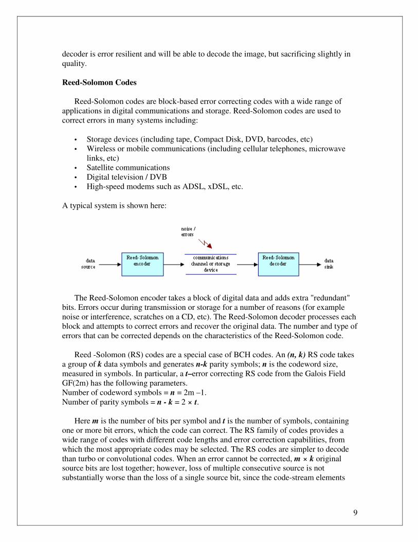
A typical system is shown here:
The Reed-Solomon encoder takes a block of digital data and adds extra "redundant"
bits. Errors occur during transmission or storage for a number of reasons (for example
noise or interference, scratches on a CD, etc). The Reed-Solomon decoder processes each
block and attempts to correct errors and recover the original data. The number and type of
errors that can be corrected depends on the characteristics of the Reed-Solomon code.
Reed -Solomon (RS) codes are a special case of BCH codes. An (n, k) RS code takes
a group of k data symbols and generates n-k parity symbols; n is the codeword size,
measured in symbols. In particular, a t–error correcting RS code from the Galois Field
GF(2m) has the following parameters.
Number of codeword symbols = n = 2m –1.
Number of parity symbols = n - k = 2 × t.
Here m is the number of bits per symbol and t is the number of symbols, containing
one or more bit errors, which the code can correct. The RS family of codes provides a
wide range of codes with different code lengths and error correction capabilities, from
which the most appropriate codes may be selected. The RS codes are simpler to decode
than turbo or convolutional codes. When an error cannot be corrected, m × k original
source bits are lost together; however, loss of multiple consecutive source is not
substantially worse than the loss of a single source bit, since the code-stream elements
10
which are being protected generally exhibit at least local dependencies, which usually
render the bits immediately following a corrupted bit useless.
Processing of an image using JPEG2000
Although JPEG2000 is able to process an image in smaller independent tiles, we
consider the entire image is processed as a single tile. Its samples are transformed into
spatial frequency sub-bands with the aid of the Discrete Wavelet Transform (DWT). The
discrete wavelet transform (DWT) is a representation of a signal x (t) ε L2 using an
orthonormal basis consisting of a countably-infinite set of wavelets. Denoting the wavelet
basis as }/)({ , ZnZktnk ∈∧∈ψ , the DWT transform pair is
∑ ∑∞
−∞=
∞
−∞=
=k n
tdtx nknk )))((()( ,, ψ
>=< )(),(,, txtd nknk ψ
∫∞
∞−
= dttxtnk )(),(,ψ
where }{ , nkd are the wavelet coefficients. Note the relationship to Fourier series and to
the sampling theorem: in both cases we can perfectly describe a continuous-time signal
x(t) using a countably-infinite (i.e., discrete) set of coefficients. Specifically, Fourier
series enabled us to describe periodic signals using Fourier coefficients {X[k] / k ε Ζ},
while the sampling theorem enabled us to describe bandlimited signals using signal
samples {X[n] / n ε Ζ}. In both cases, signals with a limited class are represented using a
coefficient set with a single countable index. The DWT can describe any signal in L2
using a coefficient set parameterized by two countable indices: }/)({ , ZnZktd nk ∈∧∈ .
Each sub-band is partitioned into small blocks, known as code-blocks. Initial
quantization and bit-plane coding are performed on these code-blocks. The bit plane
coder makes three passes over each magnitude bit plane of the quantized sub-band
sample indices. Each code-block is coded independently. Each resolution in the DWT is
partitioned into so-called precincts. Precincts have no impact on sample data
transformations or coding. Precincts are not a partition of image data, but of the
compressed code-block bit-streams, which are used to reconstruct that resolution. The
precinct size can be chosen independently for different resolutions. Compressed data
from each precinct is collected into so called packets. Each packet consists of a packet
head and a packet body, which together identify and contain incremental contributions
from the code-block bit-streams belonging to the relevant precinct. In order to extract the
code-block bit-stream contributions from a packet body, it is necessary to correctly
decode the header of that packet and all preceding packets from the same precinct.
The figure below illustrates the organization of a JPEG2000 code-stream, having only
one tile and one tile-part. As seen in the figure, the code-stream commences with a
sequence of marker segments, each of which commences with a specific marker code and
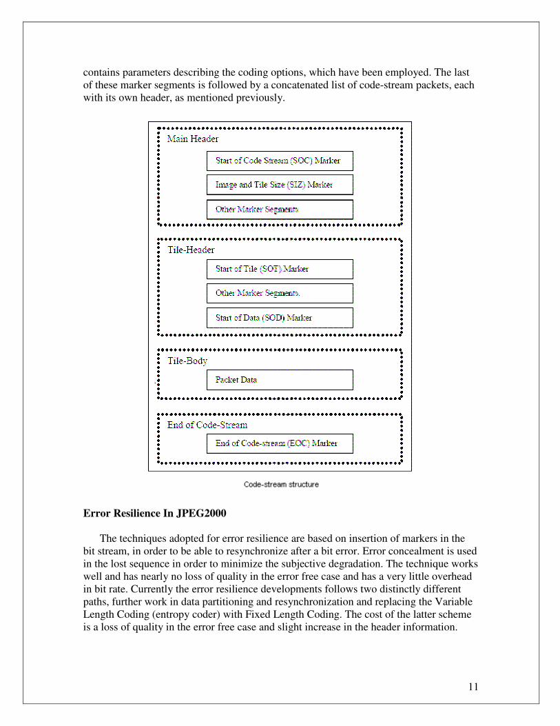
11
contains parameters describing the coding options, which have been employed. The last
of these marker segments is followed by a concatenated list of code-stream packets, each
with its own header, as mentioned previously.
Error Resilience In JPEG2000
The techniques adopted for error resilience are based on insertion of markers in the
bit stream, in order to be able to resynchronize after a bit error. Error concealment is used
in the lost sequence in order to minimize the subjective degradation. The technique works
well and has nearly no loss of quality in the error free case and has a very little overhead
in bit rate. Currently the error resilience developments follows two distinctly different
paths, further work in data partitioning and resynchronization and replacing the Variable
Length Coding (entropy coder) with Fixed Length Coding. The cost of the latter scheme
is a loss of quality in the error free case and slight increase in the header information.
12
Partitioning the code-stream into different segments helps to isolate errors in one
segment and prevent them from propagating through the entire code-stream. For the
purpose of this investigation, we assume that all of the marker segments, which precede
the concatenated list of code-stream packets, remain intact. These marker segments
contain crucial coding parameters, without which nothing can be decoded.
JPEG2000 provides several error resilience tools, to help minimize the impact of
corruption in the packet data.
• One of these tools is the ERTERM predictable termination strategy. When the
arithmetic codeword generation process, used to produce each code-block bit-stream,
is terminated at the end of each coding pass, using this predictable termination
strategy, a suitably equipped decoder can localize any errors encountered in the bit-
stream with reasonably high confidence. Once an error is detected, the decoder can
discard the affected coding pass and all future coding passes, thereby minimizing the
impact of the error upon reconstructed image quality. We refer to this strategy as
error concealment.
• JPEG2000 also offers an additional feature to assist the decoder in localizing errors in
a code-block’s bit-stream. In this case, a special four-symbol code, known as a
SEGMARK, is inserted immediately before the first new coding pass in each
magnitude bit-plane. A bit error in any of the preceding coding passes is likely to
corrupt at least one of the four SEGMARK symbols, allowing the decoder to detect
the error.
When used together, these two mechanisms allow most code-block bit-stream errors
to be detected and concealed. The main component of the code-stream is the packet.
Encoding and decoding of code-blocks are independent processes, so bit errors in the bit
stream of any one code-block will not affect other code-blocks. The code block
contributions inside a packet body can be independently decoded. However, if a packet
header is corrupt, the code-block contributions from that packet’s body cannot generally
be correctly recovered. Moreover, subsequent packet headers for the same precinct are
often not decodable, without the previous ones. This suggests that errors in a packet
header can be expected to have a more devastating impact on image quality than errors in
the packet body.
Partitioning resolutions into multiple precincts can also contribute to error resilience.
The use of smaller precincts results in a large number of packets being formed. This also
results in an increase in the total amount of packet header information, which slightly
reduces the overall compression efficiency. On the other hand, selecting smaller precincts
substantially reduces the number of code-blocks affected by a single packet header error.
For this reason, one would expect to find that smaller precincts yield more robust code-
streams. While this appears to be true when the data is not protected by FEC codes, the
impact of smaller precincts on error resilience may not be significant when FEC codes
are carefully assigned to the protection of the various packet header and body
components.
13
It is sufficient simply to apply an FEC coding strategy directly to the compressed
packet data bytes. The reason for this is that no two consecutive packet data bytes are
permitted to form a code in the range FF90 through FFFF, this range being restricted for
the signaling of code-stream markers. In particular, the resync marker (SOP=FF91) plays
an important role in error resilient parsing of the code-stream. SOP marker segments may
optionally be inserted in front of each code-stream packet. In the event of a corrupt
packet header, the length of that packet's header and/or body are likely to be misread, so
that the next packet's SOP marker will not be encountered in the expected location. The
SOP marker segment contains a sequence number, which may be used to recover from
errors of the form described above.
The RS encoded data is used to build a modified code-stream, whose packet data
consist of the codewords produced by the RS coder. Packets are then aligned on RS
codeword boundaries, rather than byte boundaries. The parity bits generated by RS
coding may result in packet data, which violates the requirement that no two consecutive
bytes may form a value in the range FF90 to FFFF. To avoid this problem, the parity bits
are collected into multiple of 7, packing each such multiple into a whole packet data byte,
whose most significant bit is 0. The result is not a legal JPEG2000 code-stream, but it is
still decodable by a slightly modified decoder. For practical applications, it would be
better to pack the parity bits into a completely separate data stream with its own resync
markers.
Another factor contributing to the error resilience of a JPEG2000 code-stream is the
number and spacing of quality layers. The first layer in a code-stream is the collection of
all first packets from each precinct in the image. The second layer consists of the second
packet from each precinct, etc. The code-block contributions associated with each quality
layer successively reduce the image distortion in an optimal way, as a function of the
number of packet bytes in those layers.
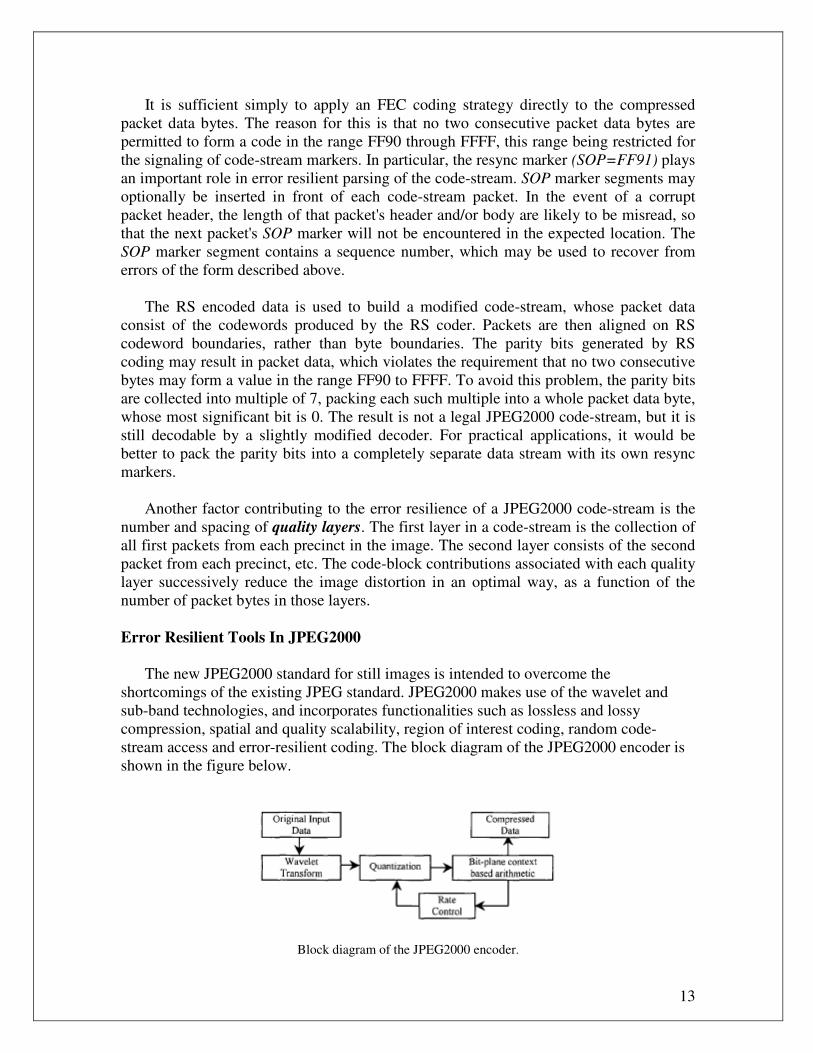
Error Resilient Tools In JPEG2000
The new JPEG2000 standard for still images is intended to overcome the
shortcomings of the existing JPEG standard. JPEG2000 makes use of the wavelet and
sub-band technologies, and incorporates functionalities such as lossless and lossy
compression, spatial and quality scalability, region of interest coding, random code-
stream access and error-resilient coding. The block diagram of the JPEG2000 encoder is
shown in the figure below.
Block diagram of the JPEG2000 encoder.
14
In JPEG2000, the image to be compressed is first divided into rectangular blocks
called tiles. This first process is optional and the entire image can be regarded as one tile.
Each tile is then wavelet transformed. The transform coefficients are quantized using a
uniform dead zone scalar quantizer. The quantized coefficients are divided into non-
overlapping rectangles called code-blocks. A bit-plane context based arithmetic coder is
used to compress the quantized coefficients code-block by code-block. The code-blocks
are coded a bit-plane at a time starting with the most significant bit-plane with a nonzero
element to the least significant bit-plane. The individual bit-planes are coded within three
coding passes. The coding passes are called significance propagation, magnitude
refinement, and cleanup. For each pass, contexts are created which are then provided to
the arithmetic coder along with the bit-stream to produce the coded data for a code-block.
The individual bit-streams, one from each code-block, are organized into packets and
distributed across a number of layers. A collection of layers comprises the final
JPEG2000 bit-stream.
Although the arithmetic coder provides a good compression performance, the
resulting coded data is highly prone to bit-errors. A single error can produce the loss of
synchronization at the decoder side resulting in corrupted decoded information. To
reduce the impact of bit-errors on compressed images, a set of error resilient tools have
been included in the JPEG2000 standard. The tools work at the entropy coding and
packet level.
• Entropy coding level
• Code-blocks
• Termination and reset of the arithmetic coder for each coding pass
• Selective arithmetic coding bypass (lazy coding mode)
• Segmentation symbols
• Packet level
• Short packet format
• Packet with resynchronization marker
The error resilient tools work as follows:
1. Quantized coefficients of different code-blocks are entropy coded independently and
errors in the coded data of a code-block are contained within that code-block.
2. The arithmetic coder can be terminated and reset after each coding pass. This allows
the arithmetic coder to continue to decode coding passes even in the presence of errors.
3. The optional arithmetic coding bypass style puts raw bits into the code stream without
arithmetic coding. This prevents error propagation to which entropy coded data is highly
susceptible.
4. A segmentation symbol is a special symbol that is coded at the end of each bit-plane.
The correct decoding of this symbol at the end of each bit-plane confirms the correct
reception of that bit-plane.
15
5. Short packets are achieved by moving the packet headers to the main header in the
PPM (Packed Packet headers-Main header) marker segment.
6. At the packet level, a SOP (Start of Packet) resynchronization marker is inserted in
front of every packet with a sequence number starting at zero.
An alternative to error resilience is to use Forward Error Correction (FEC)
techniques. FEC will add information to the bit stream and result in an increased rate
without any quality improvements in the error free case. FEC is also considered as a
system layer issue and therefore not part of the standard. However, considering the use of
FEC when designing an error resilient mode can offer extra benefits, virtually free of
cost.
Unequal Channel Protection Of JPEG2000 Images
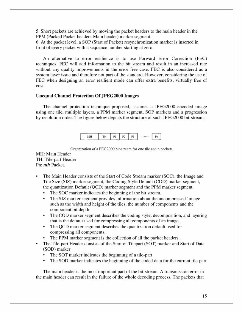
The channel protection technique proposed, assumes a JPEG2000 encoded image
using one tile, multiple layers, a PPM marker segment, SOP markers and a progression
by resolution order. The figure below depicts the structure of such JPEG2000 bit-stream.
Organization of a PEG2000 bit-stream for one tile and n packets
MH: Main Header
TH: Tile-part Header
Pn: nth Packet.
• The Main Header consists of the Start of Code Stream marker (SOC), the Image and
Tile Size (SIZ) marker segment, the Coding Style Default (COD) marker segment,
the quantization Default (QCD) marker segment and the PPM marker segment.
• The SOC marker indicates the beginning of the bit stream.
• The SIZ marker segment provides information about the uncompressed ‘image
such as the width and height of the tiles, the number of components and the
component bit depth.
• The COD marker segment describes the coding style, decomposition, and layering
that is the default used for compressing all components of an image.
• The QCD marker segment describes the quantization default used for
compressing all components.
• The PPM marker segment is the collection of all the packet headers.
• The Tile-part Header consists of the Start of Tilepart (SOT) marker and Start of Data
(SOD) marker
• The SOT marker indicates the beginning of a tile-part
• The SOD marker indicates the beginning of the coded data for the current tile-part
The main header is the most important part of the bit-stream. A transmission error in
the main header can result in the failure of the whole decoding process. The packets that
16
conform to the layers used to encode the image information comprise the rest of the bit-
stream. If single-quality-layer compression is used, the initial packets contain the
compressed information corresponding to the most significant coefficients (e.g. the
coefficients from the low frequency sub-bands), while the later packets carry the details
of the image. Bit-errors in the initial packets severely affect the quality of the
reconstructed information, as opposed to bit-errors in the later packets, which only
degrade the details of the image.
Protecting the entire bit stream equally is not the best option, since the contribution of
the later packets to the final quality of the image is not as important as that of the initial
packets. Moreover, an equal error protection technique would mean a significant increase
on the transmission bit-rate. When the image is compressed using multiple quality layers,
the coded data of each code-block is distributed across a number of layers. Each layer
consists of a few number of consecutive bit-plane coding passes from each code-block,
including all sub-bands. Each layer successively and monotonically improves the quality
of the image. The initial layers contain the initial coding passes of each code-block.
These initial coding passes correspond to the most significant bit-planes of each code-
block.
Transmission errors in these bit-planes have a high impact on the quality of the
reconstructed image, as opposed to bit-errors in the later layers, which contain the least
significant bit-planes. Protecting the whole bit-stream is not the best option; since the
contribution of the last layers to the final quality of the image is not as important as that
of the first layers. Based on this observation, unequal channel protection is applied to
JPEG2000 images by means of a RCPC code (UCP-RCPC).
We first divide the JPEG2000 bit-stream into two parts, A and B. The main header,
the tile-part header and n initial packets comprise part A. The remaining packets comprise
part B. Part A contains the main header which is used by the decoder to successfully
decompress the received code stream. Due to the difference of importance between parts
A and B of the code stream, the technique applies channel protection only to part A by
means of a RCPC code. The use of RCPC codes gives the possibility to study different
coding rates without changing the coding-decoding structure. The number of packets n
included in part A depends on the desired target quality that the protected information is
to have. The target quality of the protected information is the quality of the reconstructed
image when only the protected information has been received, assuming no errors during
the transmission. Here, we use the peak signal-to-noise ratio (PSNR) as the quality metric
of the reconstructed image. The higher the target PSNR is, the more packets are included
in part A.
When the image is compressed using a single quality layer, the n packets included in
part A contain all the coding passes used to encode the samples of the code-blocks
contained in the low frequency sub-bands. In this case, the protection technique assigns
the same channel protection to all the bit-planes of these samples. For the case of
multiple-quality-layer compression, the n packets included in part A contain the first
coding passes used to encode the samples of the code-blocks contained in the low
17
frequency sub-bands. In this case, we are protecting the most important bit-planes of the
samples of those code-blocks contained in the n packets. As more packets are included in
part A, the most important bit planes of more code-blocks are protected. It is important to
notice that for the same target PSNR, more packets are likely to be included in part A
when multiple-quality-layer compression is used.
Channel Models
The simulation is done using three different input-output channel models as
transmission environment.
• Binary Symmetric Channel is used to simulate normally distributed errors.
• The Gilbert-Elliot channel model is used to simulate burst of errors commonly found
in wireless channels. The Gilbert-Elliot two-state channel model is a simple model
that incorporates the memory associated with fading channels. The model has one
good state and one bad state, and its output depends statistically on previously sent
and received information. In each state, the channel behaves as a BSC with a certain
probability of error, Pg for the good state and Pb for the bad state. The bad state is
characterized by a high probability of error, as opposed to the good state whose
probability of error is low. At each bit interval, the state changes according to the
transition probabilities q1 and q2, where q1 is the transition probability from the good
state to the bad state and q2 is the transition probability from the bad state to the good
state. In order to model the bursts of errors present in a fading channel, the probability
of staying in one state should be higher than the probability of leaving the state. The
average bit error rate (BER) of a Gilbert-Elliot channel is given as
This model was used to generate error patterns for the simulation of a wireless channel.
• Jakes’ model is used to simulate Rayleigh fading channels, such as those
encountered in personal mobile communications. When dealing with wireless
communications and mobile receivers, the transmitted signal undergoes fades as the
receiver moves. The duration and frequency of these fades depend on the speed of the
receiver, the probability of error for the digital modulation technique used, and the
average received signal-to-noise ratio E over the channel. A channel with such
characteristics is said to be a flat-fading channel and the envelope of the received
amplitude is Rayleigh distributed. Jakes' model has two filtered noise components.
These two noise components are comprised of a set of six or more sinusoidal signals.
Their frequencies are chosen to approximate the U-shaped Doppler spectrum. One
extra component at the maximum Doppler spread is also added, but with a smaller
amplitude. Assuming a FSK transmission over a flat-fading channel the probability of
error can be expressed as:
18
where E is the energy per bit, η /2 is the power spectral density and SNR is the received
signal-to-noise ratio. The bit error rate (BER) of the channel can be expressed in terms of
the average signal-to-noise ratio (SNR) as:
For the simulation of Rayleigh fading channels, this model was used to generate error
patterns.
Simulation Results
• Results - 1
The robustness of the coding technique was evaluated with a 512 x 512 gray level
image. The image is compressed using lossy compression with 6 levels of decomposition
and one tile. The size of the code block is set to 64 x 64, and the size of the precinct is set
to 128 x 128. The arithmetic coder is terminated after each coding pass, and segmentation
symbols are added to the encoded bit-stream. We have multiple-quality-layer
compression, with an overall transmission rate of 0.5 bpp.
For one-quality-layer compression, twenty-four packets comprise the resulting bit-
stream, and the initial three packets contain the compressed information corresponding to
the last three levels of decomposition. According to the protection technique described
earlier, we have protected the main header (including the tile-part header) and the three
initial packets using a RCPC code while the rest of the packets have been left
unprotected. The initial three packets correspond to a compressed image with a PSNR of
25.78 dB. For multiple-quality-layer compression, five layers have been used, and 128
packets comprise the resulting bit stream. According to the protection technique earlier,
we have set the target PSNR of the protected information to 25.78 dB. The four initial
packets of the bit stream roughly correspond to this target PSNR. Therefore, we have
protected the main header (including the tile part header) and four initial packets using a
RCPC code. The initial four packets are part of the first layer, and they contain the initial
coding passes of the code-blocks that comprise the last four levels of decomposition.
The main header and the packets to be protected are divided into blocks of 32 bytes.
An RCPC code is applied to each of these blocks of bytes. The rate of the RCPC code is
set according to the channel conditions. The protected information is transmitted first,
followed by the rest of the unprotected packets. A convolutional interleaver of depth 60
interleaves the encoded information prior transmission. In order to obtain different rates,
the mother code of rate 1/4 and generator matrix g = [155 123 137 1471], in octal
notation, was punctured with a period of eight. The decoding process was performed
using the Viterbi algorithm. Each channel condition has been tested with 100 independent
trials.
19
A normalized Doppler spread of 0.0002 is obtained with a carrier frequency of 900
MHz, a data rate of 15 kbps and a mobile speed of 3.6 kmph. When the header presents
severe bit-errors, the JPEG2000 decoder may not be able to decode the received
information. It is observed that the average PSNR for multiple-layer-compression is
about 1 dB better at all channel BER’s than the average PSNR for single-quality layer
compression for UCP-RCPC. These results show that multiple-quality-layer compression
performs better under noisy channel conditions. When the bit-planes are distributed
across more than one layer, it is possible to assign more protection to the most significant
bit-planes, reducing or eliminating the protection assigned to the least significant bit-
planes. If a single quality layer is used, all the bit-planes of a code-block are grouped
together in the same packet. In this case, protecting a packet results in assigning the same
protection to all bit-planes, ignoring their significance. When the channel conditions are
not favorable, convolutional codes are not capable to handle long bursts of errors. This
results in a poor performance of the UCPRCPC technique for Rayleigh fading channels
with a low SNR and a high BER. A better performance can be obtained by increasing the
convolutional interleaver depth, but there is a penalty in the total number of bits
transmitted as initial “zero” bits in the memory of the interleaver have to be flushed.
• Results - 2
We simulate a Binary Symmetric Channel (BSC) with bit error rates (BER) of 10 ^-4
and 10^-3. Error rates of these magnitudes are typical in wireless communication
systems. A 2560× 2048 monochrome test image is coded to a total size corresponding to
1.0 bits per sample, including the cost of all FEC codes. All noisy simulations are
repeated 100 times for each set of test conditions. Image quality is assessed in terms of
the Mean Squared Error (MSE), taken over all 100-simulation runs, and expressed in
terms of the PSNR.
In particular, we compare the reconstructed image quality obtained when no error
resilience features are enabled, with the quality obtained when resync (SOP) marker
segments are inserted, and then when both resync markers and decoder error concealment
are employed. In the last case, both the ERTERM and SEGMARK features mentioned
previously are employed when constructing the original code-stream.
We also compare the reconstructed image quality of a code-stream when only one
quality layer is used, with the quality obtained when the code-stream is organized in six
quality layers. It is clear that using multiple precincts can improve the error resilience of
an unprotected JPEG2000 code-stream. While multiple quality layers have some benefit,
this benefit largely disappears when multiple precincts are also used. The real advantage
of layers for error resilience is realized only when error correction codes are introduced.
We may categorize FEC protection schemes as either Equal Protection (EP) schemes
or Unequal Protection (UP) schemes. EP schemes assign the same amount of protection
to the entire code-stream. On the other hand, UP schemes provide different levels of
20
protection to different elements in the code-stream; data, which is more sensitive to
errors, is protected more heavily than the less sensitive data.
Results were obtained using two different protection schemes. For Scheme-1, the
(15,9) RS code is applied to all packet data uniformly. In Scheme-2, all packet data is
uniformly coded with the weaker (15,13) code. For both of these EP schemes we employ
resync markers together with the error concealment tools mentioned previously. We see
that RS coding has a considerable impact on the reconstructed image quality. Among the
several schemes investigated we find that, if we code the first three layers using the
(15,9) code, the next 2 layers with the (15,11) code and the last layer with the (15,13)
code, we can achieve improved results at lower bit error rates. Also worth noting is the
fact that the noiseless compression performance improves substantially. This is because
the strongest codes are used to protect only the initial quality layers, which contain many
fewer data bytes than the later layers, which are protected with less redundancy.
For higher BER conditions, an unequal error protection scheme is still preferred, but
we must select yet stronger codes for the initial quality layers. For scheme-4, we code the
first layer with a (15,7) code, the next three layers with the (15,9) code and the final two
layers with a (15,11) code. This strategy was found to yield the best results, out of several
schemes investigated at the higher BER. The use of unequal error protection can improve
the PSNR at high error rates, while also improving the noiseless compression efficiency.
Simple code assignments can be devised which are able to offer reasonable efficiency
simultaneously over a wide range of bit error rates, without excessively damaging the
noiseless compression efficiency. We also observe that spacing layers more closely (two
layers for each factor of 2, change in the cumulative layer bit rate), we can improve the
image quality by 1 dB at lower bit error rates as compared to scheme-1. Image quality
appears to deteriorate slightly when multiple precincts are used.
The loss in performance associated with multiple precincts is due to the additional
cost associated with independently coding each packet header and aligning the packet on
a whole codeword boundary. This cost reduces the noiseless compression performance by
0.3dB and 0.5dB, respectively, for the {256}, {128}, {64} and 128x128 precinct cases
considered. While some of this performance loss is generally recovered when bit errors
are introduced, the effect is insufficient to warrant a conclusion that multiple precincts are
beneficial in the context of FEC coding.
Conclusion
• An unequal channel protection technique for JPEG2000 images was presented. The
technique exploits the hierarchical structure of the JPEG2000 bit-stream and protects
only the main header and n initial packets. The protection technique takes into
account compression using a single quality layer and compression using multiple
quality layers. The unequal channel protection is achieved by means of a RCPC code.
By unequally protecting the JPEG2000 bit-stream, better resilience to channel errors
has been achieved without a significant increase in the bandwidth requirements for
21
the channel protection bits. The robustness of the technique has been tested over
different noisy channels with different channel coding rates. Simulation results show
an improvement on the average PSNR and the probability of successful decoding the
received images compared to the case of no channel protection.
• We also examined the impact of the existing error resilience tools offered by
JPEG2000, including error concealment; resync markers, layering and precincts. We
find that these tools are of substantial benefit and that dividing the image resolutions
into multiple precincts is advantageous for error resilience. The availability of
multiple quality layers is of little benefit unless we introduce forward error correction
codes, to protect the layers unequally. Unequal protection of the quality layers is
definitely beneficial and allows a code-stream to be efficiently protected over a range
of different channel error conditions. We have not found the use of multiple precincts
to be of any benefit when RS codes are used to protect the compressed data, either
equally or unequally across quality layers.
• The transmission over noisy channels can be done using different systems in order to
achieve a good Quality of Service. If one works with a retransmission system there is
a problem with large transmission delays when the channel is noisy. This situation is
not good when compressed images are transmitted because the size of the data will be
large, and that implies a big delay. The use of non-transparent channels and an error
resilient mode might solve these problems. Here, residual bit errors are present in the
received data, which gives degradation in the decoded image quality. The tradeoffs
between time delay and quality degradations have been presented where the
retransmission rate is translated to a specific ber. Error resilience aims to solve the
problem of decoding in the presence of residual errors by ensuring a robust coding
mode. These solutions are based on a different coding in order to protect the data and
make it more robust against the errors. Such decoding methods are being developed
under JPEG 2000.
References
[1] V. S. Sanchez and M. K. Mandal,” Robust Transmission Of Jpeg2000 Images Over
Noisy Channels,” IEEE Transactions on Consumer Electronics, Vol. 48, No. 3, August
2002
[2] Ambarish Natu and David Taubman,” Unequal Protection of JPEG2000 Code-
Streams in Wireless Channels,” IEEE Global Telecommunications Conference
(GLOBECOM), volume 1, pages 534-538, November 2002
[3] Andrew Perkis and Daniel Gonzalo Cardelo,” Transmission of Still Images Over
Noisy Channels,” Signal Processing and Its Applications, 1999. ISSPA '99. Proceedings
of the Fifth International Symposium on Volume 2, 22-25 Aug. 1999 Page(s):789 - 792
[4]Phil Schniter,”Discrete Wavelet Transform,” http:/cnx.rice.edu/content/m10436/latest/
[5] R. C. Gonzalez and R. E. Woods, Digital Image Processing, Prentice-Hall, 2002
[6]http://stargate.ecn.purdue.edu/~ips/tutorials/j2k/