Embed Size (px)
DESCRIPTION
ESCOWELD-EPOXY-GROUT-SYSTEMS.pdf
Citation preview
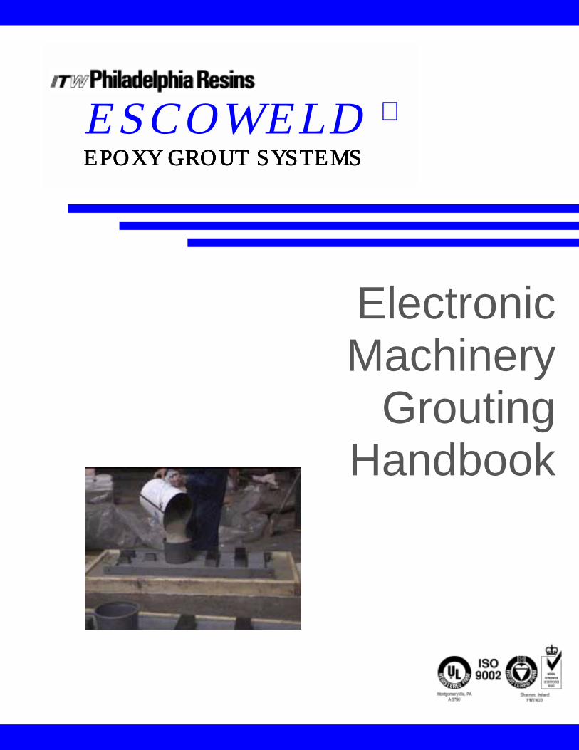
ESCOWELD
EPOXY GROUT SYSTEMSEPOXY GROUT SYSTEMSEPOXY GROUT SYSTEMSEPOXY GROUT SYSTEMS
Electronic Machinery
Grouting Handbook
Grouting Handbook: May, 1999
ESCOWELD®
EPOXY GROUT SYSTEMSITW PHILADELPHIA RESINS
130 Commerce DriveMontgomeryville, PA 18936
Tel.: 215-855-8450Fax: 215-855-4688
www.escoweld.com
GROUTING HANDBOOK
ESCOWELD® MACHINERY

ESCOWELD ESCOWELD ESCOWELD ESCOWELD EPOXY GROUT SYSTEMS EPOXY GROUT SYSTEMS EPOXY GROUT SYSTEMS EPOXY GROUT SYSTEMS Table of Contents
A Guide for the Selection of Epoxy Grouts ..........................................1-7; 16; 17
Epoxy Grout Specifications ..................................................Attachment A – 8-15
Grouting Preparation Tips............................................................................18-20
Escoweld Grouting Procedures .....................................................................21-22
Pregrouting Pump Baseplates .............................................................................23
Cold Weather Grouting .....................................................................................24
Hot Weather Grouting.......................................................................................25
Installation Specification for Pumps and Drivers When Using Epoxy Grouts ...........................................................................26-47
Installation Specifications Checklist..............................................................48-56
Void Repair Procedure .................................................................................57-60
Drawings ......................................................................................................61-70
Grouting Seminars ........................................................................................71-74
Cementitious Grouts.....................................................................................75-79
Informative Reprints from Trade Publications....................Attachment B – 80-91
Joint Surface Preparation Standards ................................Attachment C – 92-104
References ......................................................................Attachment D – 105-106
Table of Contents

ESCOWELD ESCOWELD ESCOWELD ESCOWELD EPOXY GROUT SYSTEMS EPOXY GROUT SYSTEMS EPOXY GROUT SYSTEMS EPOXY GROUT SYSTEMS A Guide For the Selection of Epoxy Grouts

1
ESCOWELD®
EPOXY GROUT SYSTEMSITW PHILADELPHIA RESINS
130 Commerce DriveMontgomeryville, PA 18936
Tel.: 215-855-8450Fax: 215-855-4688
www.escoweld.com
A GUIDE FOR
THE SELECTION
OF EPOXY GROUTS
2
By: Richard D. Myers, ITW ESCOWELD® SYSTEMS MANAGERRaul Martinez, ITW ESCOWELD® MARKETING MANAGER
Bruce Shipley, P.E. TECHNICAL MANAGER, ITW PHILADELPHIA RESINS
High performance epoxy grouts have been used to maintain precise and perma-nent alignment of all types of machinery for approximately 40 years. Mostmechanical and structural engineers who are involved in machinery installationshave extensive experience with epoxy grouts for new installations and for fastturnaround foundation repairs.
In refineries, chemical/petrochemical plants and pulp and paper mills, mainte-nance costs average nine percent. This is an area where significant savings can be accrued by using fast-cure, “fast turnaround” epoxy grouts.
Although there have been improvements in the formulation of cementitiousgrouts, including the development of nonmetallic cementitious grouts in the mid-1960’s, cementitious grouts should not be considered for applications thatrequire any of the following conditions:
SPECIFY EPOXY GROUTS FOR:❐ excellent vibration damping for both dynamic loads and high compression
static loads.
❐ high compressive strength and bond high strength
❐ permanent monolithic support with void-free intimate contact betweenmachinery bedplates and concrete foundations
❐ resistance to impact, abrasion and attack by fuels, lubricants, solvents,caustics and other harsh chemicals
❐ resistance to shrinkage, fretting and shear loads
❐ serviceability within 24 hours—instead of 3 to 5 days
Applications for high performance epoxy grouts range from crane rails to pumps. Typical applications for specific industries include:
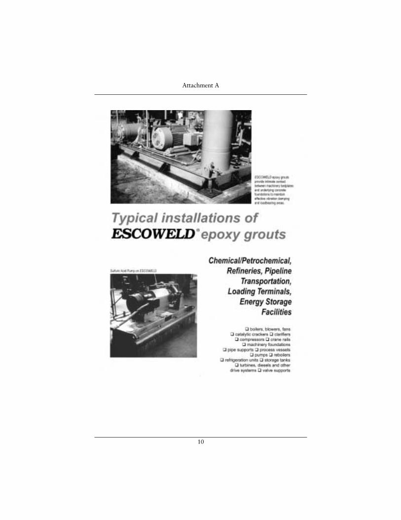
Chemical/Petrochemical, Oil Refineries, Pipeline Transportation, Loading Terminals & Energy Storage Facilities• boilers, blowers, fans • catalytic crackers • clarifiers • compressors • cranerails • equipment/machinery foundations • pipe supports • process vessels • pumps • reboilers • refrigeration units • storage tanks • turbines, diesels,other drive systems • valve supports
A Guide for Selecting Epoxy Grouts
3
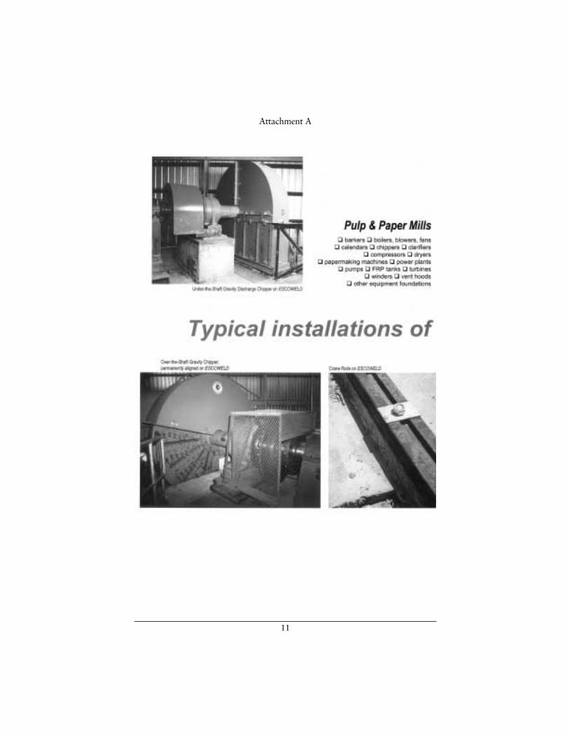
Pulp & Paper Mills• barkers, chippers • boilers, blowers, fans • calendar • clarifiers • compres-sors • dryers • FRP tanks • papermaking machines • power plants • pumps • turbines • winders • vent hoods • foundations for other equipment
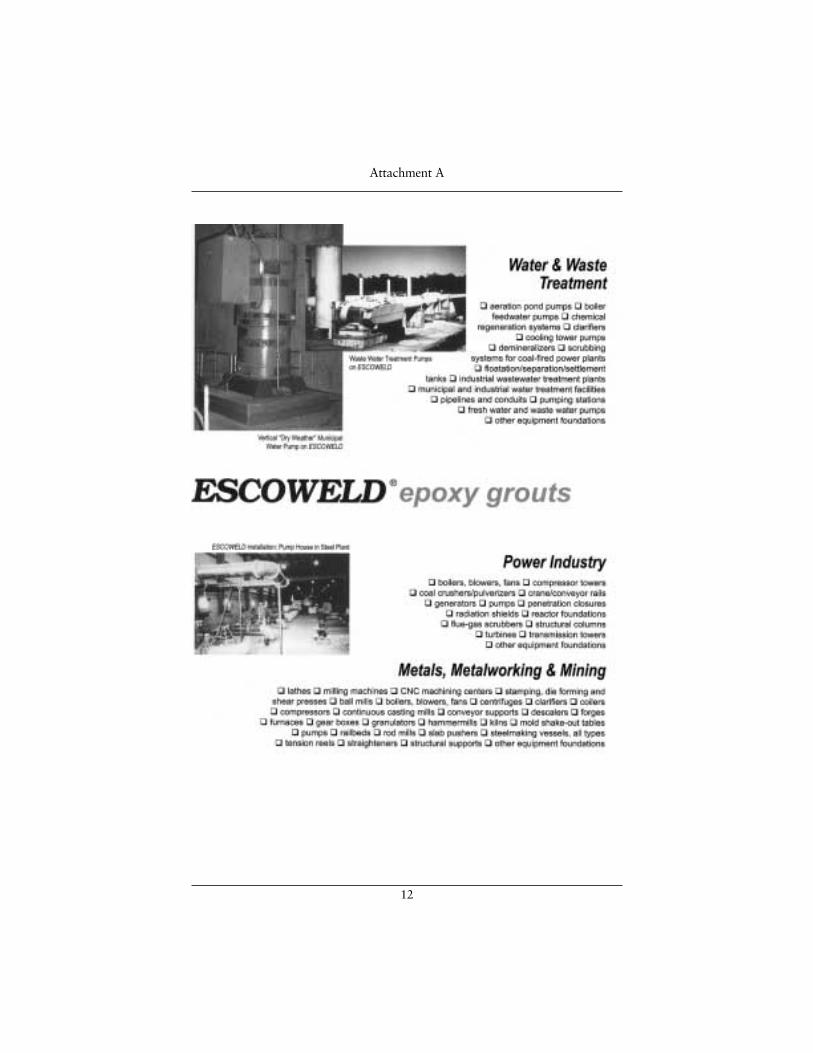
Power Industry• boilers, blowers, fans • coal crushers/pulverizers • compressor towers • crane/conveyor rails • generators • pumps • penetration closures • radiation shields • reactor foundations • flue-gas desulfurization scrubbers• structural columns • transmission towers • turbines • foundations forother equipment
Metals, Metalworking & Mining• mills • boilers, blowers, fans • centrifuges • clarifiers • CNC machiningcenters • coilers • compressors • continuous casting mills • conveyor supports• descalers • forges • furnaces • gear boxes • granulators • hammermills • kilns • lathes • milling machines • mold shake-out tables • pumps • rodmills • slab pushers • stamping, die-forming and shear presses • steelmakingvessels • transfer car rail beds • tension reels • straighteners • structuralsupports • and foundations for other equipment
Water & Waste Treatment• aeration pond pumps • boiler feedwater pumps • chemical regenerationsystem • clarifiers • cooling tower pumps • demineralizers • scrubbingsystems for coal-fired power plants • flotation/separation/settlement tanks • industrial wastewater treatment plants • municipal and industrial watertreatment facilities • pipelines and conduits • pumping stations • sewagepumps • sewage treatment plants
Because an epoxy grout must maintain intimate void-free contact betweenmachinery/equipment bedplates and underlying concrete foundations to provide a monolithic damping pad with an effective loadbearing area, it is essential tospecify a structural epoxy.
A Guide for Selecting Epoxy Grouts
4
PROPERTIES OF EPOXIESReliability & Durability: The reliability of an epoxy grout to behave in apredictable manner during placement—and curing—is critical. To ensurepredictable, reliable and repeatable results, epoxy grouts are packaged inpremeasured units.
The reliability of a grout depends upon a manufacturer’s formulation; control of quality materials, blending procedures, and packaging, storage, handling andshipping. ISO-9002 Certification and a corporate commitment to total QualityControl Programs are other factors to consider.
Compressive Strength: This property should be determined in accordance withASTM C 579 (“Test Method for Compressive Strength of Chemical-ResistantMortars and Monolithic Surfacings”), Method A or B. The generally acceptedminimum compressive strength for high performance epoxy grouts is 12,000 psi in 24 hours.
Bond Strength: The bond strength of an epoxy grout to cast iron or steelbedplates shall be in excess of 1700psi, and to portland cement should exceedthe tensile strength of concrete, per ASTM C 307.
Creep: Creep is defined as deformation (without failure) under the action of aconstant load. All materials exhibit creep. If creep does not exceed a material’smodulus of elasticity, there will be no permanent deformation and no damage to the material; it will always return to its original size/shape when the load is released.
The creep of a high performance epoxy grout should be less than 0.005 in./in. when tested to ASTM C 1181 with a constant load of 400 pounds per squareinch at temperatures between 70° to 140°F.
Tensile Strength: Although an epoxy grout is subjected primarily to compressiveloads, the tensile strength and modulus of elasticity play important roles inmaintaining structural integrity. The tensile strength should not be less than 1700 psi and the modulus of elasticity should be at least 1,800,000 (1.8 x 10⁶) psi,per ASTM C 307.
Working Time: The working time for pouring/placement of an epoxy grout is directly related to its heat-generation exotherm. Standard epoxy grouts, forexample, will have a maximum 45 minutes of working time at 75°F. Working time will decrease as material volume and ambient temperatures increase. ForEscoweld high strength epoxies, the working time will be 120 minutes at 75°F.Pouring/ placement should be planned to take this working time into consideration.
A Guide for Selecting Epoxy Grouts
5
Thermal Coefficient of Expansion: All materials will change dimension asambient temperature changes. Most materials expand as their temperaturesincrease; and they contract as their temperatures decrease. The amount ofexpansion or contraction is termed the “Coefficient of Expansion”. It isexpressed in decimal fractions of an inch per inch of dimension per degreeFahrenheit (or as centimeters/centimeter/°Centigrade).
Many epoxy grouts have vastly different ‘coefficients’ than concrete. Therefore, it is important to specify a high performance epoxy with expansion/contractioncharacteristics compatible to concrete. The thermal expansion of a highperformance epoxy grout should be less than 17 x 10-6 in./in./°F when tested to ASTM C 531.
Peak Exotherm: The maximum temperature rise (peak exotherm) will occurwhen a liquid epoxy begins to gel into a solid. With Escoweld deep-pour epoxygrouts, there is a gentle exothermic reaction during gel.
A peak exothermic temperature of less than 110°F, per ASTM D 638 and a geltime of at least 120 minutes allow dissipation of any excessive cast-in stresses toreduce or eliminate the possibility of cracking common to high exotherm grouts. A gentle exothermic reaction also allows dependable single pours of 18" (1000 mm)or even deeper, thus saving 20 days or more compared to traditional machineryinstallations and concrete reconstruction.
MATCH GROUT TO APPLICATIONDepth of pour is the single most important criterion in the selection of a highperformance epoxy grout.
Table 1 lists the properties of Escoweld® 7505E/7530, a high performance groutthat combines a gentle 24-hour cure with a peak exotherm of 95° to 110°F. Thisgrout has a low coefficient of thermal expansion (CTE), which is very similar tothe CTE’s of metal baseplates and underlying concrete.
By reducing cast-in thermal stresses, Escoweld® 7505E/7530 helps to minimize or eliminate cracks in structural epoxy foundations, including single pours up to 4 ft. thick.
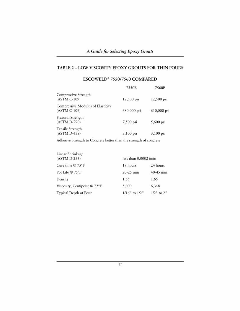
Table 2 provides similar information for Escoweld® 7550E and Escoweld® 7560E,a pair of epoxy grouts formulated for special applications that require thinpours, high flows and narrow clearances. Escoweld® 7550E is commonly usedfor pours of 1/16" to 1/2". Escoweld® 7560E is used for pours requiring a depthof 1/2" to 2".
A Guide for Selecting Epoxy Grouts
6
HOT AND COLD WEATHER GROUTING:Cold Weather: For cold weather grouting, all concrete and metal surfaces in contactwith an epoxy grout should be “conditioned” to a temperature of at least 50°F; andthis temperature should be maintained at least 48 hours prior to and 24 hours aftergrouting. It is recommended that in colder climates grouting should be scheduledduring the warmer part of the day to help improve flowability and curing.
Pours with hard-to-control cold-weather conditions below 60°F may require theuse of an accelerator. For any grouting procedure conducted below 65°F, anEscoweld representative should be contacted.
Hot Weather: For grouting in hot weather shading or other methods should beused to cool baseplates below 90°F. Concrete, steel and forms should be shadedfrom direct sunlight 48 hours prior to placing the grout and kept shaded at leastone day after grout placement. Ideally, the placement of epoxy grout should bescheduled for early morning in hotter weather to take advantage of coolerfoundation and steel surfaces. The foundation creates the greater heat sink.
Regardless of ambient weather conditions, all epoxy grout components (resin,hardener and aggregate) should be stored in a dry, weatherproof area until allcomponents reach a temperature between 65° and 80°F. Since the aggregate isthe major portion of a mix, its temperature will be the most critical in deter-mining the final mix temperatures.
Unlike cementitious grouts, epoxy grouts are prepackaged. Hence, there are noproblems in assuring uniformly consistent mixtures with predictable properties. With epoxy grouts, there is no potential for “over- or under-watering”.
The temperature to be maintained during the cure will depend upon the cureschedule required. In general, epoxies will not cure below 40°F. Consult thegrout manufacturer for advice on techniques best suited to each application.
ON-SITE TECHNICAL SERVICESite-specific assistance is available from knowledgeable Escoweld distributors. Their expertise includes hands-on experience with • pumps, compressors and other rotating equipment • expansion joints • concrete restoration and foun-dation rebuilds (with short turnaround times) • rails, bedplates and skids (forequipment without fabricated baseplates) • leveling devices • and anchor bolts.
A Guide for Selecting Epoxy Grouts
7
For detailed information about state-of-the-art epoxy grouts, on-site technicalsupport and information about informative hands-on seminars which cover allaspects of successful baseplate grouting, contact:
❐ Scott Bullentini, Escoweld® National Sales Manager, telephone 225-922-7731, fax 225-922-7732
❐ Dick Myers, Escoweld® Western Regional Manager, telephone 281-429-7552, fax 281-429-7915
❐ Raul Martinez, Escoweld® Eastern Regional Manager, telephone 215-855-8450, fax 215-855-4688
A Guide for Selecting Epoxy Grouts
8
Attachment A

9
Attachment A
10
Attachment A
11
Attachment A
12
Attachment A
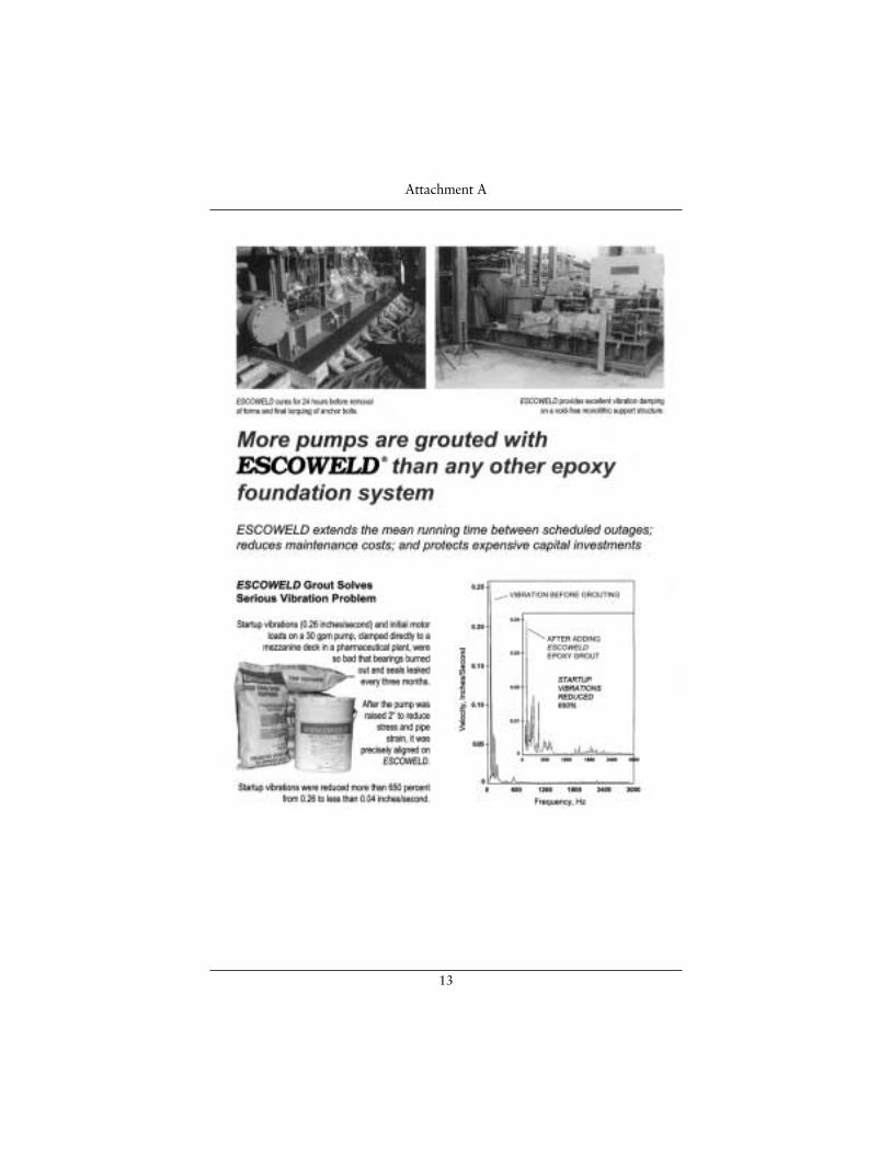
13
Attachment A
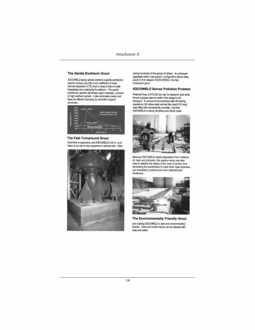
14
Attachment A
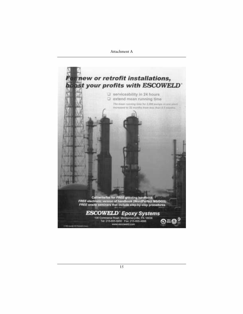
15
Attachment A
16
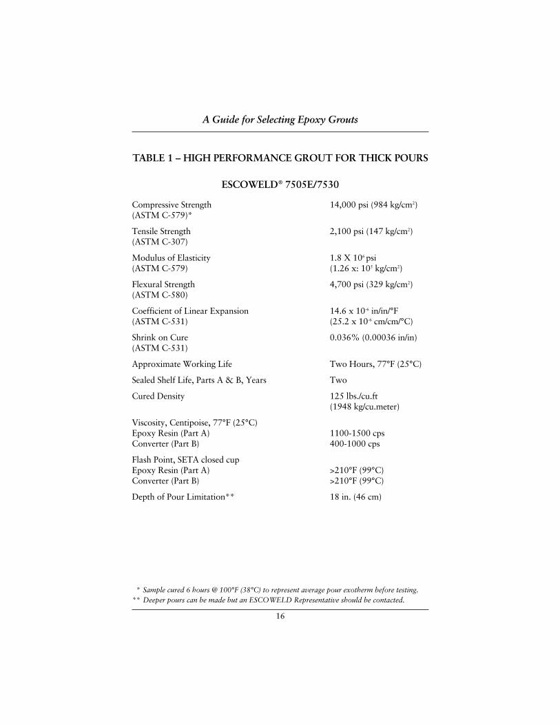
TABLE 1 – HIGH PERFORMANCE GROUT FOR THICK POURS
ESCOWELD® 7505E/7530
Compressive Strength 14,000 psi (984 kg/cm2)(ASTM C-579)*
Tensile Strength 2,100 psi (147 kg/cm2)(ASTM C-307)
Modulus of Elasticity 1.8 X 10⁶ psi(ASTM C-579) (1.26 x: 105 kg/cm2)
Flexural Strength 4,700 psi (329 kg/cm2)(ASTM C-580)
Coefficient of Linear Expansion 14.6 x 10⁻⁶ in/in/°F(ASTM C-531) (25.2 x 10⁻⁶ cm/cm/°C)
Shrink on Cure 0.036% (0.00036 in/in)(ASTM C-531)
Approximate Working Life Two Hours, 77°F (25°C)
Sealed Shelf Life, Parts A & B, Years Two
Cured Density 125 lbs./cu.ft(1948 kg/cu.meter)
Viscosity, Centipoise, 77°F (25°C)Epoxy Resin (Part A) 1100-1500 cpsConverter (Part B) 400-1000 cps
Flash Point, SETA closed cupEpoxy Resin (Part A) >210°F (99°C)Converter (Part B) >210°F (99°C)
Depth of Pour Limitation** 18 in. (46 cm)
A Guide for Selecting Epoxy Grouts
** Sample cured 6 hours @ 100°F (38°C) to represent average pour exotherm before testing. ** Deeper pours can be made but an ESCOWELD Representative should be contacted.
17
TABLE 2 – LOW VISCOSITY EPOXY GROUTS FOR THIN POURS
ESCOWELD® 7550/7560 COMPARED
7550E 7560E
Compressive Strength(ASTM C-109) 12,500 psi 12,500 psi
Compressive Modulus of Elasticity(ASTM C-109) 680,000 psi 610,000 psi
Flexural Strength(ASTM D-790) 7,500 psi 5,600 psi
Tensile Strength(ASTM D-638) 3,100 psi 3,100 psi
Adhesive Strength to Concrete better than the strength of concrete
Linear Shrinkage(ASTM D-256) less than 0.0002 in/in
Cure time @ 75°F 18 hours 24 hours
Pot Life @ 75°F 20-25 min 40-45 min
Density 1.65 1.65
Viscosity, Centipoise @ 72°F 5,000 6,348
Typical Depth of Pour 1/16" to 1/2" 1/2" to 2"
A Guide for Selecting Epoxy Grouts

ESCOWELD ESCOWELD ESCOWELD ESCOWELD EPOXY GROUT SYSTEMS EPOXY GROUT SYSTEMS EPOXY GROUT SYSTEMS EPOXY GROUT SYSTEMS Grouting Preparation Tips
18
Pouring epoxy grout under a piece of equipment is only a small part of a groutjob. Days of preparation and many man-hours are involved before the grout isactually poured. These pre-grout preparations can be the difference between a grout job lasting for the life of a piece of machinery, or only a few years ormonths. With this in mind, we want to design a grouting system that will beresistant to both static and dynamic loading, and accept within limits, unbalancedforces that are imposed upon it by a piece of rotating or reciprocating equipment.The grouting system should utilize expansion joints to reduce the possibility ofcracking due to thermal and mechanically induced stress.
I. PREPARATION OF NEW CONCRETE
A. “Cure Time”
It is recommended that a shrinkage test as per ASTM-C157-80 beperformed. Epoxy grout should never be poured on “green” or uncuredconcrete. If a hydration test is not performed, the following canapproximate concrete cure times:
1. Standard concrete: 5 bag mix, 21-28 days, depending on climate and mix ratio.
2. High early concrete: 6-7 bag mix, 7 days, depending on climate and mix ratio.
3. The compressive strength of all new concrete should be a minimumof 3,000 psi with a minimum tensile strength of 300 psi beforepouring epoxy grout.
B. Concrete Surface Preparation
1. All laitance must be removed and good aggregate exposed. This is usually achieved by light chipping to a depth of 1/2" to 3/4". This chipping is done after the concrete is sufficiently cured.Chipping should be accomplished using hand held chipping guns.(Never use jackhammers on new concrete.)
2. Horizontal foundation edges should be chipped to approximately 1-1/2" x 1-1/2" at a 45° angle. This will help reduce the possibilityof edge lifting during seasonal cyclic temperature changes (summerto winter).
3. The concrete surface should be free of any loose material, oil, water or any other contaminant that would prevent the grout frombonding. The use of oil free compressed air or vacuum cleaners ishighly recommended.
Grouting Preparation Tips
19
II. PREPARATION OF OLD CONCRETE
Same as for new concrete except the foundation should be inspected for any cracking and appropriate action taken. Consideration should begiven to cracks in existing concrete foundation prior to pouring epoxygrout. Consult ESCOWELD® Grouting Systems for corrective action.
III. PREPARATION OF FOUNDATION BOLTS
Bolt embedment depth into the concrete varies depending on thefoundation design. Free length should be 6 times bolt diameter forcentrifugal and 12 times bolt diameter for recip applications. The boltshould be wrapped with weather stripping, pipe insulation, or suitablematerial that will prevent the grout from bonding to the bolt shank. The minimum wrap thickness will be 1/4" to the side. When bolt sleevesare used, they should be filled with ITW Philadelphia Resins ExpansionJoint Compound to prevent the epoxy grout from bonding to thefoundation and restricting bolt strech during final torque. The sleeveshould not protrude into the grout.
IV. LEVELING PADS
A. Leveling pads used in conjunction with vertical jackscrews should beround and a minimum of 1/2" thick. The diameter of the leveling padshould not be less than 3 inches, per Drawing Nos. 001 and 002.
B. When the equipment is in place and final alignment is obtained,grease the jackscrew prior to pouring the epoxy grout. Make certainthat jackscrews are not flared or have damaged threads.
C. After the grout is poured and cured, remove the jackscrew and fillthe hole with ITW Philadelphia Resins Expansion Joint Compoundor install a 1/4" long bolt to plug the hole and prevent contaminantsfrom reaching the grout interface.
V. GROUT FORMS
Grout forms should be constructed of 3/4" plywood (minimum) andbraced both vertically and horizontally with 2"x 4" lumber. The face of the form to come in contact with the grout should be waxed with 3coats of wax to prevent bonding of the grout to the forms. A hardwoodfloor paste wax is normally used. The grout forms should be liquid tight and sealed to the vertical concrete face with silicone caulk. Allinside right angles (90°) should be chamfered to prevent stress risers and possible cracking.
Grouting Preparation Tips
20
VI. EXPANSION JOINTS
Expansion joints are incorporated into large epoxy grout pours to reduce the possibility of cracking, especially when temperaturedifferentials of 50°F are encountered. They should be a maximum of 3/4" thick and be designed to prevent any oil or water migration to the concrete foundation. Placement of the expansion joints should be between each anchor bolt or break up a grout pour into sections. No two grout jobs are the same; therefore, ESCOWELD® GROUTINGSYSTEM, ITW PHILADELPHIA RESINS should be consulted forrecommended expansion join placement and design.
VII. ENVIRONMENTAL CONTROL
During the summer, the foundation and equipment to be grouted shouldbe covered with some type of shelter to keep the uncured grout frombeing exposed to direct sunlight This covering will also protect thefoundation from dew, mist or rain. It should be erected 48 hours priorto grouting and remain up for 24 hours after grouting is completed.
In the winter, a suitable covering to allow the foundation and equipmentto be completely encapsulated should be constructed. A heating sourceshould be applied so as to raise the entire foundation and equipmenttemperature to above 65°F for at least 48 hours prior to and after grou-ting. The epoxy grout liquids and aggregate should be preconditioned to65°F or above to assure adequate flow. If preconditioning is not possible,contact your local ITW Escoweld Representative.
VIII. BASE PLATE PREPARATION
All steel surfaces that will come in contact or be embedded intothe epoxy grout will be prepared as follows:
1. Sandblasted to “white metal”.
2. All sharp corners, both vertical and horizontal, that will beembedded in the grout, should be radiused (1/2" minimum) to reduce stress risers and the possibility of cracking the grout.
3. Sides and bottom of steel surfaces should be coated with ITWPhiladelphia Resins Rust Inhibitive Primer (primer should be applied according to manufacturers recommendations).
4. As final check before mixing and pouring make sure that there are no pockets that can trap air. A 3/8" vent hole may mean thedifference between success and failure. We are striving for 100% void free grout job.
Grouting Preparation Tips
ESCOWELD ESCOWELD ESCOWELD ESCOWELD EPOXY GROUT SYSTEMS EPOXY GROUT SYSTEMS EPOXY GROUT SYSTEMS EPOXY GROUT SYSTEMS ESCOWELD ESCOWELD ESCOWELD ESCOWELD Grouting Procedures
21
ESCOWELD® GROUTING PROCEDURES1. All material should be stored in a dry warm location (65-80°F) at least three
days before use.
2. Prepare concrete foundations, anchor bolts and leveling screws according to individual instructions covering these items.
3. Wax forms heavily with at least three coats of paste wax. Forms must besubstantial and well braced. All corners, joints, bottoms must be sealed withsilicone caulk for water tightness. All forms should have a 45° chamfer stripinstalled to prevent stress risers.
4. Anchor bolt-free length must be wrapped with duct seal or electriciansplastic tape to prevent grout from contacting the bare metal. Grout stickingto the anchor bolt will prevent the elongation necessary to develop the holddown force. Failure to do this will result in broken anchor bolts.
5. Leveling screws must be greased to permit removal prior to the final torque.Do not use shim packs as a leveling device unless it is planned to removethem prior to final torque application.
6. Leveling screw pads should be minimum of 1/2" thick with minimum diam-eter of 3". Corners of pad must be rounded to approximately 1/8" radius toprevent stress cracking. Set leveling screws on the chipped concrete surface. Set the pad with quick set cement or ITW Philadelphia Resins RepairCompound. With jacking bolt pads secure and level, set and level base with leveling screws.
7. Underside of steel base plate must be sandblasted to SSPC-SP 6 Spec. If base cannot be set within 24 hours of blasting, the underside must becoated with ITW Philadelphia Resins Rust Inhibitive Primer.
Escoweld® Grouting Procedures
22
MIXING PROCEDURES8. Open one unit ESCOWELD® 7505E. The 5 gallon can contains both
Part A and Part B.
9. Pour contents of B component pail into A component pail. Mix the contents of A pail with a Jiffy type mixer for 3 minutes. These mixers will introduceless air entrapment than a propeller or paddle type mixer. Whipping air intothe mix must be avoided.
10. Fill B component pail with mixture from A component pail. Mix the B pailapproximately 30 seconds wetting all inside surfaces of B pail with themixed resins. Pour contents of B pail back into A pail, draining B pail well.Mix A pail approximately 20 seconds. The B pail will now have a coatingthat will harden making disposal completely non-hazardous.
11. Pour contents of the mixed liquids into a mortar mixer. Start mixer paddlerotating at a speed of no more than 25 r.p.m.
12. Add the required amount of 7530 aggregate at a slow even rate.
13. When aggregate in the mixer is wetted, mix an additional 1-1/2 minutes inwarmer climates and 3 minutes in colder environments. At the end of themix period, dump into wheelbarrow, or suitable transport container andplace in forms.
14. When forms are filled to required depth, clean all tools and equipment withwater immediately.
15. Level the completed pour and clean off excess grout that has come upthrough vent holes.
16. When final cure has been achieved, usually 24 hours depending ontemperatures, back off the leveling screws and remove them. Perform the final torque. Check level and alignment.
Escoweld® Grouting Procedures

ESCOWELD ESCOWELD ESCOWELD ESCOWELD EPOXY GROUT SYSTEMS EPOXY GROUT SYSTEMS EPOXY GROUT SYSTEMS EPOXY GROUT SYSTEMS Pre-Grouting of Pump Base Plates
23
THE BENEFIT OF PRE-GROUTING PUMP BASES WITH EPOXY GROUT ARE1. A bond to the steel baseplate greater than 2000 psi is achieved.
2. A compressive strength greater than 10,000 psi is achieved within 24 to 48 hours after placement.
3. 100% bearing area against the baseplate underside.
FROM THE END USER POINT OF VIEW1. The up front cost associated with the new technology will increase shipping
weight from the OEM’s facility but not necessarily the freight charges.
2. The increased cost of pre-grouting should not be any more than what wouldnormally be experienced at the plant level. Actually the overall cost ofgrouting from a labor standpoint should be significantly reduced.
3. This pre-grouting will eliminate the need to pressure inject improperlygrouted pump bases. Pressure injection can and will result in seriousproblems when accomplished by inexperienced personnel. Over pressuringwhen injecting an epoxy resin system under the baseplate can actually lift or bow the base, and in some cases, result in damage to the coupling endsection of the pump.
4. The pump base will be easier to grout to the foundation.
5. Vibration damping will be enhanced.(ESCOWELD® has a vibration damping capability 8 times greaterthan cement grout)
6. Baseplate deformation or distortions in the field when using highexothermic epoxy is eliminated.
(ESCOWELD® has the lowest exothermic reaction of all the epoxy grouts)
WARNINGAny epoxy grout system that limits depth of pour to 6 inches or less should beavoided when using the pre-grouted inverted technique. These high exothermicgrouts will not have the benefit of foundations for heat sink. The resulting heatcan cause baseplate deformation and warping of the mounting surfaces.
Pregrouting Pump Baseplates
INSTALLATION SPECIFICATION FOR
PRE-GROUTED BASEPLATES
ESCOWELD ® EPOXY GROUT SYSTEMSEPOXY GROUT SYSTEMSEPOXY GROUT SYSTEMSEPOXY GROUT SYSTEMS
130 Commerce Drive Montgomeryville, Pennsylvania 18936
Pre-Grouted Baseplate Specification Page 2 of 23
Installation Specification for Pre-Grouted Baseplates 1.0 General
1.1. Summary
1.1.1. This specification prescribes requirements for the furnishing and installation of Escoweld® 7505E/ 7530 epoxy grout for use in the pre-grouting of equipment baseplates.
1.2. References: The publications listed
below form part of this specification to the extent referenced. If there is a discrepancy between the references and this specification, then this specification shall govern.
1.2.1. ASTM (American Society for
Testing Materials) 1.2.2. ASTM C-531-95: Standard test
method for linear shrinkage and co-efficient of thermal expansion of chemical resistant mortars, grouts and monolithic surfacing and polymer concretes.
1.2.3. ASTM C-579-96: Standard test methods for compressive strength and compressive modulus of chemical resistant mortars, grouts, monolithic surfacings and polymer concretes.
1.2.4. ASTM C-307-88: Standard test method for tensile strength of chemical resistant mortars, grouts and monolithic surfacings.
1.2.5. ASTM D-2471-88: Standard test method for gel time and peak exothermic temperature of reacting thermosetting resins.
1.2.6. Steel Structures Painting Council: SSPC-SP6 Standard/NACE No. 3 Commercial Blast Clearing (see Appendix I, copy of SSPC-SP6)
1.2.7. American Petroleum Institute: API 610 – 8th Edition – Centrifugal Pumps for General Refinery Service
1.2.8. API 686 – 1st Edition – Recommended Practices for Machinery Installation and Installation Design
1.3. Test Reports
1.3.1. Copies of test reports, including test data, shall be certified by an independent laboratory, verifying that manufactured epoxy grouts meet or exceed the performance require-ments in accordance with ASTM C-531-95, ASTM C-579-96, ASTM C-307-88, ad ASTM D-2471-88.
1.3.2. Epoxy grout specified shall be Escoweld® 7505E/7530 or equal and will meet the minimum requirements of tests as herein specified.
1.3.3. Linear shrinkage of the epoxy grout shall be less than 0.040% and thermal expansion less than 15x10-6 in/in/ºF when tested by ASTM C-531-95.
1.3.4. The compressive strength of epoxy grout shall be a minimum 12,000 psi in 7 days when tested by ASTM C-579 Method B.
1.3.5. The tensile strength shall be determined by ASTM C-307-88 and shall not be less than 1,700 psi.
1.3.6. The compressive modulus of elasticity shall be determined by ASTM C-579-96 and shall not be less than 1.8x10⁶ psi.
1.3.7. The gel time and peak exothermic temperature shall be determined by ASTM D-2471-88. Peak exothermic temperature shall not exceed 110ºF when a specimen 6” diameter x 12” high is used. Gel time shall be at least 150 minutes.
Pre-Grouted Baseplate Specification Page 3 of 23
1.4. Product Delivery and Handling
1.4.1. Delivery
1.4.1.1. Deliver manufactured grouts in manufacturers pack-aging, including mixing and installation instructions.
1.4.1.2. Deliver epoxy grout hardener and resin in sealed, pre-measured containers.
1.4.1.3. Deliver grout aggregate in sound, dry packages.
1.5. Storage
1.5.1. All epoxy grout materials shall be stored inside and kept dry and free of moisture in its original shipping containers.
1.5.2. Storage temperature shall be maintained between 50ºF and 80ºF. Grouting materials shall be kept between these temperatures for a minimum of 48 hours prior to mixing and placement.
1.5.3. The epoxy grout aggregate shall be stored inside and kept dry.
1.5.4. In hot weather, due to the accelerated rate of curing at higher temperatures, the epoxy grout liquids (Parts A & B) and aggregate should be pre-conditioned to 70ºF - 80ºF before mixing and placement begins.
1.5.5. In cold weather (temperatures below 65ºF) the grouting materials (including the aggregate) must be stored in unopened containers, dry at a temperature of 70ºF - 80ºF for at least 24 hours prior to mixing and placement. In addition, in temp-eratures below 65ºF, the baseplate should also be pre-conditioned for 24 hours to a temperature of 65ºF minimum prior to mixing and placement.
1.5.6. For ambient temperatures below 65ºF, fabricate a temporary shelter around the baseplate to be pre-grouted and pre-warm the baseplate for at least 24 hours (e.g., the entire area around the baseplate including the baseplate itself must be brought to 65ºF for 24 hours to ensure uniform baseplate temperature prior to pre-grouting).
1.6. Technical Services
1.6.1. Before pre-grouting is scheduled to begin, a manufacturer’s technical representative shall conduct a grouting seminar at the job site.
1.6.2. Review all grouting steps and manufacturers instruction with those who will actually perform grouting operations.
1.7. Equipment
1.7.1. The following equipment should be specified for mixing and placement:
1.7.1.1. A mortar mixer, 25 rpm
or greater, 5-7 cubic foot 1.7.1.2. Two wheelbarrows, 3
cubic foot size 1.7.1.3. 3/8” to ½” variable speed
drill motor for mixing epoxy liquids
1.7.1.4. Medium-size jiffy mixer
1.7.2. For grout mixing, use only a mortar mixer with moving paddles inside a drum. Do not use concrete mixers with fins attached to a rotating drum.
Pre-Grouted Baseplate Specification Page 4 of 23
2.0 Baseplate Preparation
2.1. Check to be sure the baseplate is manufactured in accordance with engineering requirements and customers’ specifications.
2.2. When the baseplate is received on site, the baseplate primer coating should be inspected for defects (i.e., chips, gouges, etc.) and repaired as per the grout manufacturer’s recom-mendation.
2.3. Baseplate surfaces (except for mounting pads and threaded holes) that will be in contact with the epoxy grout shall be coated with an epoxy primer or an inorganic zinc silicate as recommended by the epoxy grout manufacturer.
2.4. Unless otherwise specified, commercially sandblast the baseplate, in accordance with SSPC-SP6, all grout contact surfaces and coat those surfaces with an epoxy primer (grout compatible) or an inorganic zinc silicate. If the baseplate can be pre-grouted within eight (8) hours after sandblasting, priming is not necessary.
2.5. All surfaces of the baseplate that will be in contact with epoxy grout shall be made free of all oil, grease and rust.
2.6. Use a spray atomizer to apply a heavy-duty degreaser prior to performing surface preparation of the primed baseplate. This will remove any residual oils or surface contaminants.
2.7. Use 80 or 100 grit Emory cloth to roughen 100% of the primed baseplate surfaces, if the primer was applied more than 30 days previous to pre-grouting.
2.8. Upon completion of surface prep-aration, perform additional cleaning using the spray atomizer.
2.9. Tape/protect any non-grouted surface such as baseplate flange faces.
3.0 Support of Baseplate Prior to Pre-
Grouting
3.1. Install any internal jackscrews and coat with “never-seez” to prevent grout bonding.
3.2. Install any and all bolts that penetrate the baseplate, i.e., coupling guard, wobble feet, etc., and coat with “never-seez” to prevent grout bonding.
3.3. Protect machined surfaces with plywood to prevent damage during inverting over of baseplate.
3.4. Invert the baseplate and support on jack-stands through anchor-bolt holes.
3.5. Add additional support as needed (based on baseplate size and dimension) at the mid-point of the baseplate using two jack-stands and a support bar transversely across the baseplate.
3.6. Level the baseplate coplanar via the use of the jack-stands.
3.7. Secure baseplate by locking down all jack-stands from the top.
4.0 Epoxy Grout Mixing and Installation
4.1. Ensure that the baseplate is still coplanar level prior to grouting, and is securely mounted to the jack-stands.
4.2. Escoweld® 7505E with 7530 aggregate epoxy type grout shall be used for the installation. The epoxy grout manufacturer’s requirements and instructions shall be strictly followed.
4.3. Rope off the work area and move all grouting material and tools inside the roped off area just before the job starts. When started, it should be completed without stopping and tools cleaned with medium pressure water immediately upon completion. Water from a fire-monitor or medium pressure plant water cleans the mixer and tools.
Pre-Grouted Baseplate Specification Page 5 of 23
4.4. Timing and proper mixing are the secrets to successful grouting. The grout supplier’s instructions must be followed implicitly. Before mixing the components together, everything else should be ready—surfaces cleaned and dry, rags, cleaning solvents available, adequate manpower and grout (an additional 25% in excess of the calculated requirement of grout should be in the area).
4.5. Epoxy grout can be manually mixed in a wheelbarrow, mortar box, or mechanical mortar mixer. For small pours, 2 units or less, use a clean wheelbarrow or mortar box and a mortar hoe. Over mixing and/or violent mixing whips air into the grout and results in voids under the baseplate. Epoxy grout density is approximately 125 lbs/ft3.
4.6. A mortar mixer is the preferred method for mixing. If used, the mortar mixer speed should not exceed 25 RPM. The mortar mixer should have a clutch to disengage the mixer blades to prevent over mixing the grout. NOTE: Do not mix partial units.
4.7. The average epoxy working time is approximately two (2) hours depend-ing on the ambient temperature. For specific times consult with the epoxy grout manufacturer.
4.8. The epoxy resin and hardener shall be mixed with a Jiffy Mixer per the grout manufacturer’s recommendations (typical three [3] minutes). After the epoxy liquid and hardener have been mixed, the mixed solution is poured into the hardener can and stirred for a minute to activate the residue hardener in the can. All the liquid is then poured into the mixer.
4.9. Aggregate is slowly added to the mixer one bag at a time. The grout should be mixed only long enough to wet out all the aggregate. For Escoweld® 7530 aggregate system,
mix an additional 1-1/2 minutes to activate the flow enhancement properties. Stop the mixer blades from rotating if the grout crew is not ready to place the wetted material. It is a requirement that the mortar mixer have a clutch to disengage the rotating paddles when required.
4.10. Epoxy grout is very viscous; however, it will flow readily, given time and positive hydraulic head. If installing below 65°F ambient temperature, consult grout manufacturer to determine if aggregate adjustment is necessary.
4.11. No push rods, chains or vibrators should be used to place epoxy grout inside baseplates.
4.12. Grouting shall be continuous until the placement of grout is complete in all sections or compartments of the baseplate. Subsequent batches of grout should be prepared so as to be ready when the preceding batch has been placed. The grouting crew should never wait on the mixing operation. The crew mixing the material should always be ahead of the placement crew.
4.13. A grout sample can be taken for each piece of equipment to be grouted. The sample shall be of sufficient size to yield three (3) 2" x 2" x 2" test samples and shall be tagged with the equipment number, ambient temperature at the time of placement. The samples should be tested in accordance with the manufacturer’s recommendations.
5.0 Grout Curing
5.1. All grout to cure 24 hours at a minimum ambient temperature of 70ºF prior to machining.
Pre-Grouted Baseplate Specification Page 6 of 23
6.0 Baseplate Machining
6.1. Pre-grouted baseplates should always be machined after grouting, as this allows all forces created from grout bonding to baseplate to completely cycle and become static.
6.2. Mounting surfaces will be machined flat to within ________ per foot.
6.3. All machine mounting surfaces will be coplanar to each other within a tolerance of ________.
7.0 Pre-Grouting Baseplate Storage and Protection
7.1. After pre-grouting, grout cure, and
machining are completed, clean underside of pre-grouted baseplate with lightly wetted rags and cover tightly with poly.
7.2. Store pre-grouted baseplate away from oils, dirt and water. NOTE: These principles should be tightly adhered to in the field/job site as well.
8.0 Shipping and Handling of Pre-Grouted Baseplate
8.1. Ship pre-grouted baseplates with poly
covering the underside to protect from contaminants while in transit.
8.2. Use traditional lifting methodology for handling of the pre-grouted baseplate (Escoweld® 7505E/7530 density is 125 lbs./ft3.
9.0 Field Grouting Procedure
9.1. Field grouting of pre-grouted baseplates should incorporate similar baseplate leveling techniques as used in traditional installations.
9.2. Never allow end user to grout final 2” between pre-grouted baseplate and
concrete with a different grout than was used in the pre-grouting. Compatible systems that ensure bonding at the interface should only be used.
10.0 Forming the Foundation
10.1. Grout forms shall be built of a minimum of 3/4" thick plywood and shall be securely braced (minimum brace size to be 2" x 4").
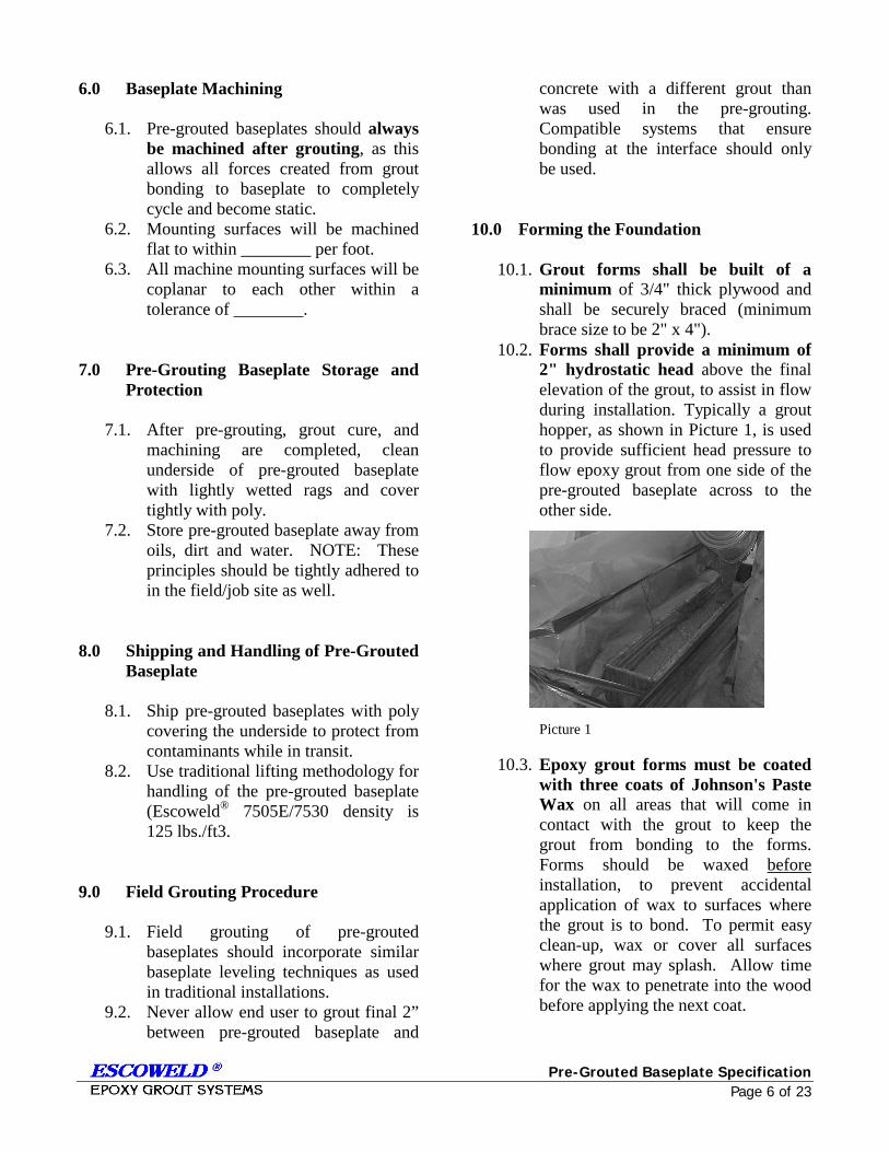
10.2. Forms shall provide a minimum of 2" hydrostatic head above the final elevation of the grout, to assist in flow during installation. Typically a grout hopper, as shown in Picture 1, is used to provide sufficient head pressure to flow epoxy grout from one side of the pre-grouted baseplate across to the other side.
Picture 1
10.3. Epoxy grout forms must be coated with three coats of Johnson's Paste Wax on all areas that will come in contact with the grout to keep the grout from bonding to the forms. Forms should be waxed before installation, to prevent accidental application of wax to surfaces where the grout is to bond. To permit easy clean-up, wax or cover all surfaces where grout may splash. Allow time for the wax to penetrate into the wood before applying the next coat.
Pre-Grouted Baseplate Specification Page 7 of 23
10.4. Before any forms are installed, all concrete surfaces that will contact epoxy grout should be free of any foreign material, such as oil, sand, water, grease, etc. (anything that could have an adverse effect on any bonding surfaces).
10.5. Forms shall be liquid-tight, because epoxy grout will flow through even the smallest opening. Any open spaces or cracks in forms, or at the joint between forms and the foundation, shall be sealed off, using RTV sealant. The outside top edges of the grout shall be chamfered at 45 o, as well as the vertical corners.
10.6. The 45o chamfer strip shall be located at the final elevation of the grout. The top of the grout, on baseplates with solid sides and soleplates, such as the pre-grouted baseplate, shall be 1.0 inch above the bottom of the baseplate or the underside of the soleplate. The grout's final elevation should not be so high as to bond the anchor bolt nut and washer.
10.7. Foundation anchor bolt sleeves shall be filled with a non-bonding, pliable material, such as Escoweld 7506. It is imperative that epoxy grout not be allowed to fill the anchor bolt sleeve.
10.8. Duxseal shall be placed around the exposed threads of anchor bolts, to prevent direct contact between the epoxy grout and anchor bolts. Install lubricated bolts into any threaded hole in the baseplate, to prevent grout from filling these holes. These bolts should be totally engaged to provide a space under the baseplate such that when the bolts are later engaged, the bolt will not jack against the grout and jack the baseplate up.
10.9. The foundation should be protected from rain with a tarp since it is important that the foundation be clean and dry at the time of grouting.
11.0 Epoxy Grout Installation
11.1. Escoweld® 7505E with 7530 aggregate epoxy type grout shall be used for the installation.
11.2. Rope off the work area and move all grouting material and tools inside the roped off area just before the job starts. When started, it should be completed without stopping and tools cleaned with medium pressure water immediately upon completion. Water from a fire monitor or medium pressure plant water cleans the mixer and tools.
11.3. Timing and proper mixing are the secrets to successful grouting. The grout supplier's instructions must be followed implicitly. Before mixing the components together, everything else should be ready--surfaces cleaned and dry, forms completed and sealed, rags, cleaning solvents available, adequate manpower and grout (an additional 25% in excess of the calculated requirement of grout should be in the area).
11.4. ESCOWELD® 7505E/7530 can be manually mixed in a wheelbarrow, mortar box, or mechanical mortar mixer. For small pours, 5 units or less, use a clean wheelbarrow or mortar box and a mortar hoe. Over mixing and/or violent mixing whips air into the grout and results in voids under the baseplate.
11.5. A mortar mixer is the preferred method for mixing. If used, the mortar mixer speed should not exceed 25 RPM. The mortar mixer should have a clutch to disengage the mixer blades to prevent over mixing the grout. NOTE: DO NOT MIX PARTIAL UNITS.
11.6. The average epoxy working time is approximately two (2) hours depending on the ambient temp-erature. For specific times consult
Pre-Grouted Baseplate Specification Page 8 of 23
with the ESCOWELD® manu-facturer’s representative.
11.7. The epoxy resin and hardener shall be mixed with a Jiffy Mixer per the grout manufacturer's recommen-dations (typical three [3] minutes). After the epoxy liquid and hardener have been mixed, the mixed solution is poured into the hardener can and stirred for a minute to activate the residue hardener in the can. All the liquid is then poured into the mixer.
11.8. Aggregate is slowly added to the mixer one bag at a time. The grout should be mixed only long enough to wet out all the aggregate. For Escoweld® 7530 aggregate system, mix an additional 1 1/2 minutes to activate the flow enhancement properties. Stop the mixer blades from rotating if the grout crew is not ready to place the wetted material.
11.9. Epoxy grout is very viscous; however, it will flow readily, given time and positive hydraulic head. If installing below 70o F ambient temperature, consult grout manu-facturer to determine if aggregate adjustment is necessary. Generally, it is best to start placing the grout at the center of one end of the baseplate or soleplate and work toward the ends in such a manner as to force the air out from beneath the baseplate or soleplate and out the vent holes, to eliminate voids.
11.10. Placing of the grout is accomplished in a manner that avoids air entrapment and a head box is used to aid in pouring the grout under the pre-grouted baseplate and across the foundation. The head box provides a hydraulic head to force the grout across the entire foundation width. NEVER allow the grout to fall below the baseplate level once the grout has made contact with the baseplate. The use of a head box
provides a surge volume for the grout as well as provides the critical hydraulic head. NOTE: No push rods, chains or vibrators should be used to place epoxy grout under baseplates.
11.11. Grouting shall be continuous until the placement of grout is complete under the entire pre-grouted baseplate and across the entire foundation. Subsequent batches of grout should be prepared so as to be ready when the preceding batch has been placed. The grouting crew should never wait on the mixing operation. The crew mixing the material should always be ahead of the placement crew.
11.12. Check the forms frequently for leaks. Leaks do not self-seal. Use Duxseal to seal the leaks. If not stopped, they will cause voids.
11.13. A grout sample can be taken for each piece of equipment to be grouted. The sample shall be of sufficient size to yield three (3) 2"x2"x2" test samples and shall be tagged with the equipment number, ambient temperature at the time of placement. The samples should be tested in accordance with the manufacturer's recommendations.
11.14. Once the epoxy grout cylinder has been completely filled, it should be placed next to the foundation of the equipment being grouted and allowed to cure for 48 hours. After 48 hours, the test cylinder should be sent to an outside test facility to be tested per the grout manufacturer's recommendation.
11.15. Forms may be removed when the epoxy grout is adequately cured. This generally occurs in approximately 24 hours when the surface becomes firm and not tacky to the touch. When a low temperature accelerator is used, follow the
Pre-Grouted Baseplate Specification Page 9 of 23
manufacturer's instructions to deter-mine the typical curing time required.
11.16. The baseplate is to remain supported by the jackscrews for 48 hours before removing them. The removal of the jackscrews will allow the full equipment weight to be distributed evenly over the grouted area. Jackscrew removal time is based on surface temperature of the foundation being 75oF or above. The jackscrew holes shall be filled with RTV or epoxy after being solvent cleaned to remove any bond breaker. A dial indicator shall be placed on the baseplate frame and coupling to indicate any movement when jackscrews are removed.
11.17. The foundation anchor bolts can now be torqued. The frame shall be dial indicated at each anchor bolt and coupling, to determine any movement during torque.
Pre-Grouted Baseplate Specification Page 10 of 23
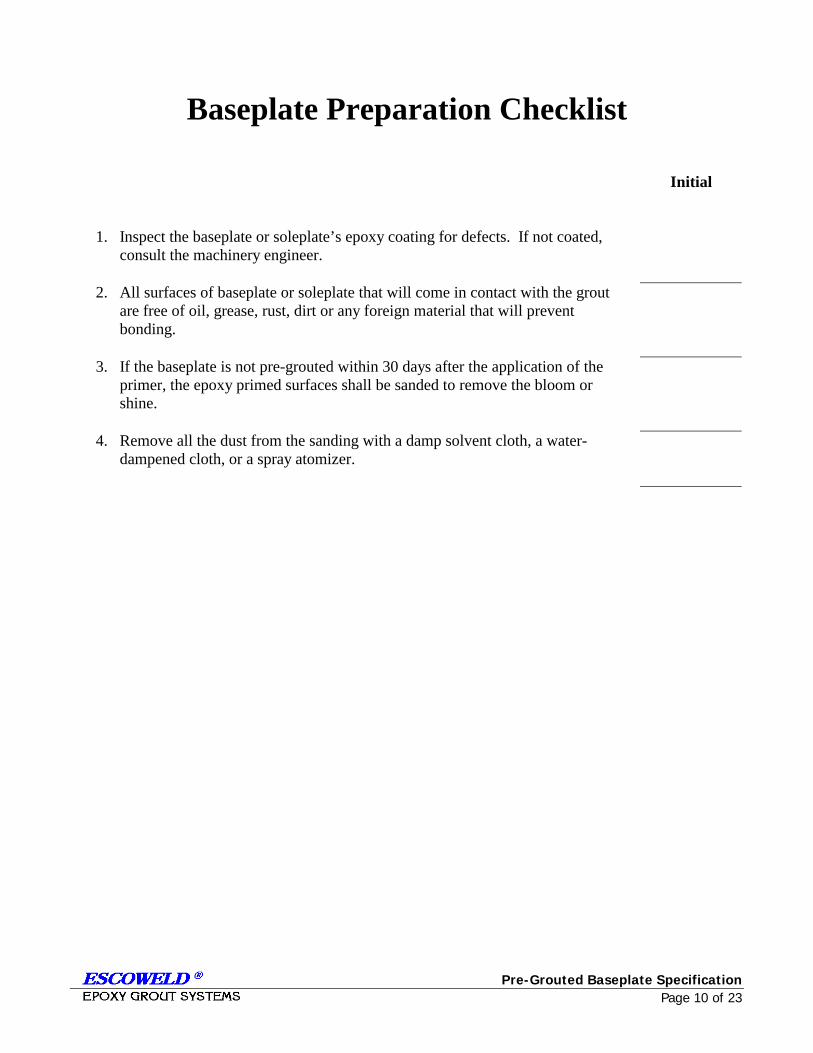
Baseplate Preparation Checklist
Initial
1. Inspect the baseplate or soleplate’s epoxy coating for defects. If not coated, consult the machinery engineer.
2. All surfaces of baseplate or soleplate that will come in contact with the grout are free of oil, grease, rust, dirt or any foreign material that will prevent bonding.
3. If the baseplate is not pre-grouted within 30 days after the application of the primer, the epoxy primed surfaces shall be sanded to remove the bloom or shine.
4. Remove all the dust from the sanding with a damp solvent cloth, a water- dampened cloth, or a spray atomizer.
Pre-Grouted Baseplate Specification Page 11 of 23
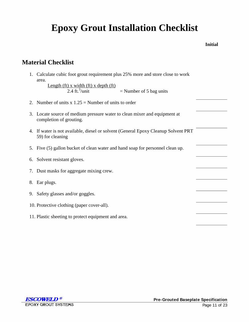
Epoxy Grout Installation Checklist
Initial
Material Checklist
1. Calculate cubic foot grout requirement plus 25% more and store close to work area.
Length (ft) x width (ft) x depth (ft)
2.4 ft.3/unit = Number of 5 bag units
2. Number of units x 1.25 = Number of units to order
3. Locate source of medium pressure water to clean mixer and equipment at completion of grouting.
4. If water is not available, diesel or solvent (General Epoxy Cleanup Solvent PRT 59) for cleaning
5. Five (5) gallon bucket of clean water and hand soap for personnel clean up.
6. Solvent resistant gloves.
7. Dust masks for aggregate mixing crew.
8. Ear plugs.
9. Safety glasses and/or goggles.
10. Protective clothing (paper cover-all).
11. Plastic sheeting to protect equipment and area.
Pre-Grouted Baseplate Specification Page 12 of 23
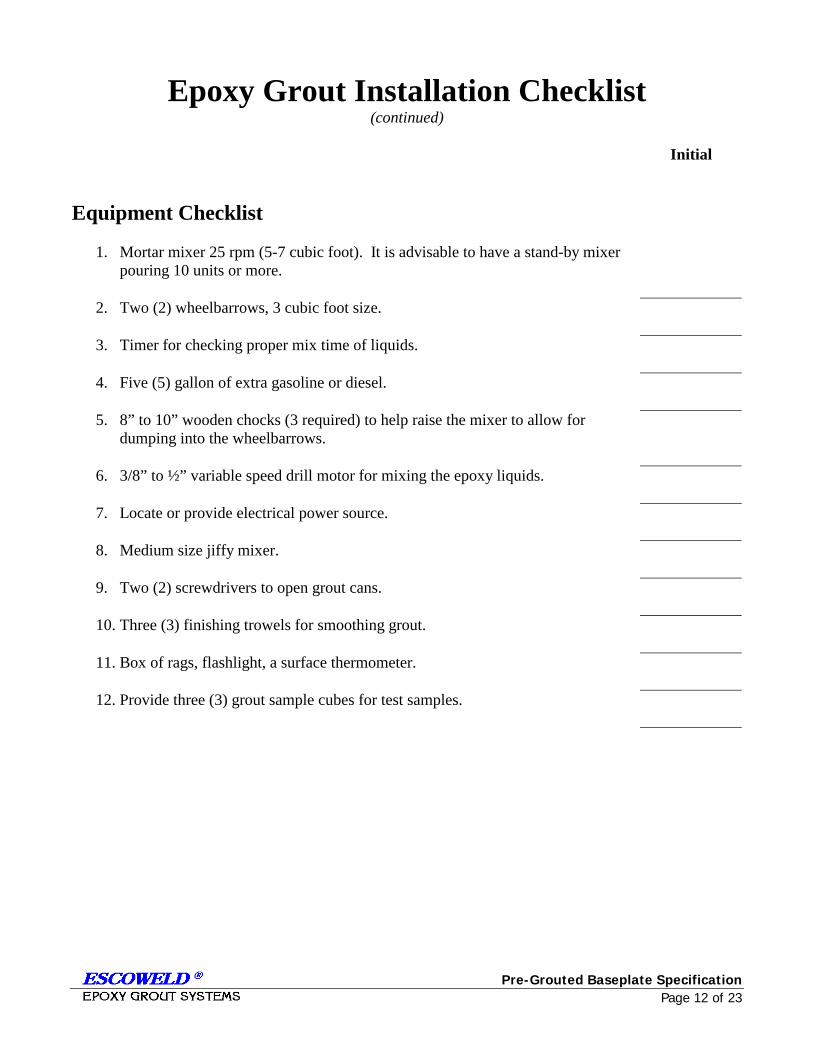
Epoxy Grout Installation Checklist (continued)
Initial
Equipment Checklist
1. Mortar mixer 25 rpm (5-7 cubic foot). It is advisable to have a stand-by mixer pouring 10 units or more.
2. Two (2) wheelbarrows, 3 cubic foot size.
3. Timer for checking proper mix time of liquids.
4. Five (5) gallon of extra gasoline or diesel.
5. 8” to 10” wooden chocks (3 required) to help raise the mixer to allow for dumping into the wheelbarrows.
6. 3/8” to ½” variable speed drill motor for mixing the epoxy liquids.
7. Locate or provide electrical power source.
8. Medium size jiffy mixer.
9. Two (2) screwdrivers to open grout cans.
10. Three (3) finishing trowels for smoothing grout.
11. Box of rags, flashlight, a surface thermometer.
12. Provide three (3) grout sample cubes for test samples.
Pre-Grouted Baseplate Specification Page 13 of 23
Epoxy Grout Installation Checklist (continued)
Initial
Grout Placement
1. The epoxy grout representative will conduct a pre-grout school to teach the proper preparation, mixing and placement procedures.
2. Organize the material and equipment close to the work area.
3. Start the mortar mixer to be sure it runs.
4. Clean the mixer of any residue.
5. Organize epoxy liquid (parts A&B) & 5 sacks Escoweld® 7530 aggregate in stacks
6. Open all cans (parts A & B) for the # of units estimated to complete the job.
7. Make sure all personnel are present, equipped and ready.
8. Mix first units of epoxy liquids (parts A & B) for three (3) minutes using the jiffy mixer and the Escoweld® timer.
9. After mixing, pour the mixed material into the empty hardener can (part B) to catalyze any residual resin.
10. Pour all the mixed liquid into the mixer.
11. The first batch of epoxy grout uses 4½ bags of aggregate to wet-out the dry mixer and wheelbarrow. All future mixes of grout will be the full 5-bag mix.
12. Mix the liquid and aggregate until the aggregate is wet, then mix 1½ minutes more. The Escoweld® 7505E/7530 flow enhancer will convert the material from dry to a very fluid mixture.
13. Dump the mixture into the wheelbarrow and transport to the baseplate.
14. Capture a grout sample at this time for future testing.
15. Continue dumping in the baseplate until all compartments are full.
16. Capture the final grout sample for testing.
Pre-Grouted Baseplate Specification Page 14 of 23
Appendix I SSPC-SP 6/NACE NO. 3 COMMERCIAL BLAST CLEANING This Steel Structures Painting Council (SSPC)/NACE International (NACE) standard represents a consensus of those individual members who have reviewed this document, its scope and provisions, its acceptance does not in any respect preclude anyone, whether he has adopted the standard or not, from manufacturing, marketing, purchasing, or using products, processes, or procedures not in conformance with this standard. Nothing contained in this standard is to be construed as granting any right, by implication or otherwise, to manufacture, sell, or use in connection with any method, apparatus, or product covered by Letters Patent, or as indemnifying or protecting anyone against liability for infringement of Letters Patent. This standard represents minimum requirements and should in no way be interpreted as a restriction on the use of better procedures or materials. Neither is this standard intended to apply in all cases relating to the subject. Unpredictable circumstances may negate the usefulness of this standard in specific instances, SSPC and NACE assume no responsibility for the interpretation or use of this standard by other parties and accept responsibility for only those official interpretations issued by SSPC or NACE in accordance with their respective governing procedures and policies, which preclude the issuance of interpretations by individual volunteers. Users of this standard are responsible for reviewing appropriate health, safety, and regulatory documents and for determining their applicability in relation to this standard prior to its use. This SSPC/NACE standard may not necessarily address all safety problems and hazards associated with the use of materials, operations, and/or equipment detailed or referred to within this document.
CAUTIONARY NOTICE: SSPC/NACE standards are subject to periodic review and may be revised or withdrawn at any time without prior notice. SSPC and NACE require that action be taken to reaffirm, revise, or withdraw this standard to no later than five years from the date of initial publication. The user is cautioned to obtain the latest edition. Forward This joint standard covers the use of blast cleaning abrasives to achieve a defined degree of cleaning to steel surfaces prior to the application of a protective coating or lining system. This standard is intended for use by specifiers, applicators, inspectors or others whose responsibility it may be to define a standard degree of surface cleanliness. The focus of this standard is commercial blast cleaning. White metal blast cleaning, near white blast cleaning, and brush-off blast cleaning are addressed in separate standards. This standard was prepared by the SSPC/NACE Joint Task Group A on Surface Preparation by Abrasive Blast Cleaning. This task group is comprised of members of both the SSPC Surface Preparation Committee and NACE Unit Committee T-6G on Surface Preparation. 1. General
1.1 This standard covers the requirements for commercial blast cleaning of steel surfaces by the use of abrasives. 1.2 The mandatory requirements are described in Sections 1 to 9 as follows:
Section 1 General Section 2 Definitions Section 3 Reference Documents
Pre-Grouted Baseplate Specification Page 15 of 23
Section 4 Procedure Before Blast Cleaning
Section 5 Blast Cleaning Methods and Operation
Section 6 Blast Cleaning Abrasives
Section 7 Procedures Following Blast Cleaning and Immediately Prior to Coating Inspection
Section 8 Inspection Section 9 Safety and
Environmental Requirements
1.3 Section 10 “Comments” and Appendix A, “Explanatory Notes” are not mandatory requirements of this standard.
2. Definition
2.1 A commercial blast cleaned surface, when viewed without magnification, shall be free of all visible oil, grease, dust, dirt, mill scale, rust coating, oxides, corrosion products, and other foreign matter, except of staining as noted in Section 2.2. 2.2 Random staining shall be limited to no more than 33 percent of each unit area of surface as defined in Section 2.6 and may consist of light shadows, slight streaks, or minor discolorations caused by stains of rust, stains of mill scale, or stains of previously applied coating.
2.3 Acceptable variations of appearance that do not affect surface cleanliness as defined in Section 2.1 include variations caused by type of steel, original surface condition, thickness of the steel, weld metal, mill or fabrication marks, heat treating, heat affected zones, blasting abrasive, and differences in the blast pattern.
2.4 When coating is specified, the surface shall be roughened to a degree suitable for the specified coating system. 2.5 Immediately prior to paint application the surface shall comply with the degree of cleaning as specified herein. 2.6 Unit area for determining staining shall be approximately 9 in2 (6400 m2) (i.e., a square 3 in x 3 in. [80 mm x 80 mm])
2.7 Visual standards or comparators may be specified to supplement the written definition. In any dispute, the written standards shall take precedence over visual standards and comparators. NOTE: Additional information on visual standards and comparators is given in Section A.4 of the Appendix
3. Reference Documents
3.1 The following documents are referenced in this standard:
Steel Structures Painting Council (SSPC) Standards: SSPC-AB1 – Mineral and Slag
Abrasives SSPC-SP1 – Solvent Cleaning SSOPC-PA – Guide 3—A Guide
to Safety in Coating Application
3.2 The latest issue, revision, or amendment of the reference documents in effect on the date of invitation to bid shall govern unless otherwise specified. If there is a conflict between the cited reference documents and this standard, this standard shall prevail unless otherwise indicated in the procurement documents (project specifications).
Pre-Grouted Baseplate Specification Page 16 of 23
4. Procedure Before Blast Cleaning
4.1 Before blast cleaning, visible deposits of oil or grease shall be removed in accordance with SSPC-SP 1 or other agreed-upon method. 4.2 Before blast cleaning, surface imperfections such as sharp fins, sharp edges, weld spatter, or burning slag shall be removed from the surface to the extent required by the procurement documents (project specification). NOTE: Additional information on surface imperfections is given in Section A.5 of Appendix A.
4.3 If a visual standard or comparator is specified to supplement the written standard, the condition of the steel prior to blast cleaning shall be determined before blasting commences.
5. Blast Cleaning Methods and Operation
5.1 Clean, dry compressed air shall be used for nozzle blasting. Moisture separators, oil separators, traps, or other equipment may be necessary to achieve this requirement. 5.2 Any of the following methods of surface preparation may be used to achieve a commercial blast cleaned surface:
5.2.1 Dry abrasive blasting using compressed air, blast nozzles, and abrasive.
5.2.2 Dry abrasive blasting using a closed-cycle, re-circulating abrasive system with compressed air, blast nozzle, and abrasive with or without vacuum for dust and abrasive recovery.
5.2.3 Dry abrasive blasting using a closed-cycle, re-circulating abrasive system with centrifugal wheels and abrasive.
5.3 Other methods of surface preparation (such as wet abrasive blasting) may be used to achieve a commercial blast cleaned surface by mutual agreement between those responsible for performing the work and those establishing the requirements. NOTE: Information on the use of inhibitors to prevent the formation of rust immediately after wet blast cleaning is given in Section A.9 of Appendix A.
6. Blast Cleaning Abrasives
6.1 The selection of abrasive size and type shall be based on the type, grade and surface condition of the steel to be cleaned, type of blast cleaning system employed, the finished surface to be produced (cleanliness and roughness) and whether the abrasive will be recycled.
6.2 The cleanliness and size of recycled abrasives shall be maintained to ensure compliance with this standard. 6.3 The blast cleaning abrasive shall be dry and free of oil, grease, and other contaminants as determined by the test methods found in SSPC-AB 1. Note that even though SSPC-0AB 1 addresses mineral and slag abrasives, the tests are applicable to most abrasives. 6.4 Any limitation or restrictions on the use of specific abrasives, quantity of contaminants, or degree of embedment shall be included in the procurement documents (project specification) covering the work, because abrasive embedment and abrasives containing
Pre-Grouted Baseplate Specification Page 17 of 23
contaminants may not be acceptable for some service requirements. NOTE: Additional information on abrasive selection is given in Section A.2 of Appendix 2.
7. Procedures Following Blast Cleaning and Immediately Prior to Coating
7.1 Visible deposits of oil, grease, or other contaminants shall be removed according to SSC-SP I1 or other method agreed upon by those parties responsible for establishing the requirements and those responsible for performing the work.
7.2 Dust and residues shall be removed from prepared surfaces by brushing, blowing off with clean dry air, vacuum cleaning or other methods agreed upon by those responsible for establishing the requirements and those responsible for performing the work. Moisture separators, oil separators, traps or other equipment may be necessary to achieve clean, dry air.
7.3 After blast cleaning, surface imperfections that remain (e.g., sharp fins, sharp edges, weld spatter, burning slag, scabs, slivers, etc) shall be removed to the extent required in the procurement documents (project specification). Any damage to the surface profile resulting from the removal of surface imperfections shall be corrected to meet the requirements, Section 2.4. NOTE: Additional information on surface imperfections is given in Section A.5 of Appendix A. 7.4 Any visible rust that forms on the surface of the steel after blast cleaning shall be removed by re-blasting the rusted areas to meet the requirements of this joint standard before coating.
NOTE: Information on rust-back (re-rusting) and surface condensation is given in Sections A.6, A.7 and A.8 of Appendix A.
8. Inspection
8.1 Work and materials supplied under this standard are subject to inspection by a representative of those responsible for establishing the requirements. Materials and work areas shall be accessible to the inspector. The procedures and times of inspection shall be as agreed upon by those responsible for establishing the requirements and those responsible for performing the work.
8.2 Conditions not complying with this standard shall be corrected. In the case of a dispute, an arbitration or settlement procedure established in the procurement documents (project specification) shall be followed. If no settlement procedure is established, then a procedure mutually agreeable to purchaser and supplier shall be used.
8.3 The procurement documents (project specification) should establish the responsibility for inspection and for any required affidavit certifying compliance with this standard.
9. Safety and Environmental Requirements
9.1 Because abrasive blast cleaning is a hazardous operation, all work shall be conducted in compliance with applicable insurance underwriter, local, state, and federal occupational and environmental health and safety rules and regulations. NOTE: SSPC-PA Guide 3, “A Guide to Safety in Paint Application”, addresses safety concerns for coating work.
Pre-Grouted Baseplate Specification Page 18 of 23
10. Comments
10.1 Additional information and data relative to this standard are contained in Appendix A. Detailed information and data are presented in a separate document, SSPC-SP COM, “Surface Preparation Commentary.” The recommendations contained in the Appendix and SSPC-SP COM are believed to contain the Appendix and SSPC-SP COM are believed to represent good practice, but are not to be considered as requirements of the standard. The sections of SSPC-SP COM that discuss subjects related to commercial blast cleaning are listed below:
Subject Commentary Section Abrasive Selection 5 Degree of Cleaning 11.6 Film Thickness 10 Wet Abrasive Blast Cleaning 9 Maintenance Painting 3.2 Rust Back (Re-Rusting) 8 Surface Profile 6 Visual Standards & Comparators 7 Weld Spatter 4.1
Pre-Grouted Baseplate Specification Page 19 of 23
APPENDIX I-A – EXPLANATORY NOTES A.1 Function:
Commercial blast cleaning (SSPC-SP 6/NACE No. 3) provides a greater degree of cleaning than brush-off blast cleaning (SSPC-SP 7/NACE No. 4) but less than near white blast cleaning (SSPC-SP 10/NACE No. 2). It should be used when a high but not perfect degree of blast cleaning is required. The primary function of blast cleaning before coating is (a) to remove material from the surface that can cause early failure of the coating system and (b) to obtain a suitable surface roughness. The hierarchy of blasting standards is as follows: white metal blast cleaning, near-white blast cleaning, commercial blast cleaning and brush-off blast cleaning.
A.2 Abrasive Selection: Types of metallic and non-metallic abrasives are discussed in the Surface Preparation Commentary (SSPC-SP COM). It is important to recognize that blasting abrasives may become embedded in or leave residues on the surface of the steel during preparation. While normally such embedment or residues are not detrimental, care should be taken to ensure that the abrasive is free of detrimental amounts of water-soluble, solvent-soluble, acid-soluble, or other soluble contaminants (particularly if the prepared steel is to be used in an immersion environment). Criteria for selecting and evaluating nonmetallic abrasives are provided in SSPC-AB 1, “Mineral and Slag Abrasives”.
A.3 Surface Profile: Surface profile is the roughness of the surface that results from abrasive blast cleaning. The profile depth (or height) is
dependent upon the size, type, and hardness of the abrasive, particle velocity and angle of impact, hardness of the surface, amount of recycling and the proper maintenance of working mixtures of grit and/or shot. The allowable minimum/maximum height of profile is usually dependent upon the thickness of the coating to be applied. Large particle-sized abrasives (particularly metallic abrasives) can produce a profile that may be too deep to be adequately covered by a single thin film coat Accordingly, it is recommended that the use of larger abrasives be avoided in these cases. However, larger abrasives may be needed to facilitate removal of thick coatings, heavy mill scale, or rust. If control of profile (minimum/maximum) is deemed to be significant to coating performance, it should be addressed in the procurement documents (project specification). Typical maximum profile heights achieved with commercial abrasive media are shown in Table 8 of the Surface Preparation Commentary SSPC-SP COM. Surface profile should be measured in accordance with NACE Standard RP0287, “Field Measurement of Surface Profile of Abrasive Blast Cleaned Steel Surfaces Using a Replica Tape,” or ASTM d 4417, “Test Method for Field Measurement of Surface Profile of Blast Cleaned Steel” (ASTM, 1916 Race Street, Philadelphia PA 19103-1187)
A.4 Visual Standards and Comparators: Note that the use of visual standards or comparators in conjunction with this standard is required only when specified in the procurement document (project specification) covering the work. However, it is strongly recommended that the procurement document require the use of visual standards or comparators. SSPC-Vis 1-89 provides color photographs for the various grades
Pre-Grouted Baseplate Specification Page 20 of 23
of surface preparation as a function of the initial condition of the steel. It should be noted, however, that a commercial blast over intact mill scale is not depicted. NACE Visual Comparators are encapsulated steel coupons depicting different finished blast conditions:
NACE Visual Comparators for Surface of New Steel Air Blast Cleaned with Sand Abrasive (complements NACE Standard TM0170) NACE Visual Comparator for Surfaces of New Steel Centrifugally Blast Cleaned with Steel Grit (complements NACE Standard TM-0175) NACE Visual Comparator for Surfaces of New Steel Centrifugally Blast Cleaned with Steel Shot (complements NACE Standard TM0175) NACE Visual Comparator for Surfaces of New Steel Air-blast Cleaned with Slag Abrasive (complements NACE Standard TM0170) The NACE Visual Comparator for Surface Finishing of Welds Prior to Coating is a plastic weld replica that complements NACE Standard RP0178. Other available visual standards are described in Section 7 of SSPC-SP COM.
A.5 Surface Imperfections:
Surface imperfections can cause premature failure when the service is severe. Coatings tend to pull away from sharp edges and projections, leaving little or no coating to protect the underlying steel. Other features that are
difficult to properly cover and protect include crevices, weld porosity, laminations, etc. The high expense to remedy the surface imperfections requires weighing the benefits of edge rounding, weld spatter removal, etc., versus a potential coating failure. Poorly adhering contaminants, such as weld slag residues, loose weld spatter, and some minor surface laminations, may be removed during the blast cleaning operation. Other surface defects (steel laminations, weld porosities, or deep corrosion pits) may be evident until the surface preparation has been completed. Therefore, proper planning for such surface repair work is essential because the timing of the repairs may occur before, during or after the blast cleaning operation. Section 4 of SSPC-SP COM and NACE Standard RP0178, “Fabrication Details, Surface Finish Requirements, and Proper Design Considerations for Tanks and Vessels to be Lined for Immersion Services,” contain additional information on surface imperfections.
A.6 Chemical Contamination: Steel contaminated with soluble salts (i.e., chlorides and sulfates) develops rust-back rapidly at intermediate and high humidity. These soluble salts can be present on the steel surface prior to blast cleaning as a result of atmospheric contamination. In addition, contaminants can be deposited on the steel surface during blast cleaning whenever the abrasive is contaminated. Therefore, removing these salts from the steel surface (preferably before blast cleaning) and eliminating sources of recontamination during and after blast cleaning can minimize rust-back. Identification of the contaminants and their concentrations may be obtained from laboratory and field tests. A number of tests for soluble salts have been examined by SSPC, ASTM, the National Shipbuilding Research Program (National Shipbuilding Research Program, c/o Naval
Pre-Grouted Baseplate Specification Page 21 of 23
Surface Weapons Center, Carderock Division, C1253, Bethesda, MD 20084-5000) and the international organization for Standardization (International Organization for Standard-ization, 1 rue de Varembe, Case Postale 56, CH-1121, Geneva 20, Switzerland).
A.7 Rust-Back:
Rust-back (re-rusting) occurs when freshly cleaned steel is exposed to moisture, contamination, or a corrosive atmosphere. The time interval between blast cleaning and rustback will vary greatly from one environment to another. Under mild ambient conditions, if chemical contamination is not present (see Section A.6), it is best to blast clean and coat a surface during the same day. Severe atmospheric environmental conditions may require more expedient coating application to avoid contamination from fallout. Chemical contamination should be removed prior to coating (see Section A.6).
A.8 Dew Point:
Moisture condenses on any surface that is colder than the dew point of the surrounding air. Therefore, it is recommended that the temperature of the steel surface be at least 5°F (3°C) above the dew point during dry blast cleaning operations. It is advisable to visually inspect for moisture and periodically check the surface temperature and dew point during blast cleaning operations and to avoid the application of coating over a damp surface.
A.9 Wet Abrasive Blast Cleaning: Steel that is wet abrasive blast cleaned may rust rapidly. Clean water should be used for rinsing (studies have shown that water of at least 15,000 ohm-cm resistivity is preferred). Inhibitors may need to be added to the water or applied to the surface immediately after blast cleaning to temporarily prevent rush
formation. The coating should then be applied before any rusting is visible. CAUTION: Some inhibitive treatments may interfere with the performance of certain coating systems.
A.10 Film Thickness: It is essential that ample coating be applied after abrasive blast cleaning to adequately cover the peaks of the surface profile. The dry film thickness about the peaks of the profile should equal the thickness known to be needed for the desired protection. If the dry film thickness over the peaks is inadequate, premature rust-through or failure will occur. To ensure that coating thicknesses are properly measured, refer to SSPC-PA 2, “Measurement of Dry Coating Thickness with Magnetic Gages”.
A.11 Maintenance and Repair Coating: When this standard is used in maintenance coating, specific instructions should be given on the extent of surface to be blast cleaned or spot blast cleaned to this degree of cleanliness. SSPC-PA Guide 4, “Guide to Maintenance Repainting with Oil Base or Alkyd Coating Systems,” provides a description of accepted practices for retaining old sound coating, removing unsound coating, feathering, and spot cleaning.
SSPC/NACE Joint Standard SSPC-SP 6/NACE No. 3
Commercial Blast Cleaning, September 15, 1994
Pre-Grouted Baseplate Specification Page 22 of 23
STEEL STRUCTURES PAINTING COUNCIL SURFACE PREPARATION SPECIFICATION NO. 2 Hand Tool Cleaning 1. Scope
1.1 This specification covers the requirements for the hand tool cleaning of steel surfaces.
2. Definitions
2.1 Hand tool cleaning is a method of preparing steel surfaces by the use of non-power hand tools. 2.2 Hand tool cleaning removes all loose mill scale, loose rust, loose paint, and other loose detrimental foreign matter. It is not intended that adherent mill scale, rust and paint be removed by this process. Mill scale, rust and paint are considered adherent if they cannot be removed by lifting with a dull putty knife. 2.3 ISO 8501-1:1988 or other visual standards of surface preparation agreed upon by the contracting parties may be used to further define the surface.
3. Reference Standards
3.1 The standards referenced in this specification are listed in Section 3.4 and form a part of the specification. 3.2 The latest issue, revision or amendment of the reference standards in effect on the date of invitation to bid shall govern unless otherwise specified. 3.3 If there is a conflict between the requirements of any of the cited reference standards and the specification, the requirements of the specification shall prevail. 3.4 STEEL STRUCTURES PAINTING COUNCIL (SSPC) SPECIFICATION: SSPC-SP 1 Solvent Cleaning
3.5 International Organization for Standards (ISOO) 8501-1:1988 Preparation of steel substrates before application of paints and related products: visual assessment of surface cleanliness, Part 1.
4. Surface Preparation Before and After Hand Tool Cleaning
4.1 Before hand tool cleaning, remove visible oil, grease, soluble welding residues, and salts by the methods outlines in SSPC-SP 1. 4.2 After hand tool cleaning and prior to painting, re-clean the surface if it does not conform to this specification. 4.3 After hand tool cleaning and prior to painting, remove dirt dust or similar contaminants from the surface. Acceptable methods including brushing, blow off with clean, dry air, or vacuum cleaning.
5. Methods of Hand Tool Cleaning
5.1 Use impact hand tools to remove stratified rust (rust scale). 5.2 Use impact hand tools to remove all weld slag. 5.3 Use hand wire brushing, hand abrading, hand scraping or other similar non-impact methods to remove all loose mill scale, all loose or non-adherent rust, and all loose paint. 5.4 Regardless of the method used for cleaning, if specified in the procurement documents, featheredges or remaining old paint so that the repainted surface can have a reasonably smooth appearance. 5.5 If approved by the owner, use power tools or blast cleaning as a substitute cleaning method for this specification.
6. Inspection
6.1 All work and materials supplied under this specification shall be subject to timely inspection by the purchaser or his authorized representative. The
Pre-Grouted Baseplate Specification Page 23 of 23
contractor shall correct such work or replace such material as is found defective under this specification. In case of dispute the arbitration or settlement procedure established in the procurement documents, if any, shall be followed. If no arbitration or settlement procedure is established, the procedure specified by the American Arbitration Association shall be used. 6.2 The procurement documents covering work or purchase shall establish the responsibility for testing and for any required affidavit certifying full compliance with the specification.
7. Safety
7.1 All safety requirements stated in this specification and its component parts apply in addition to any applicable federal, state and local rules and requirements. They also shall be in accord with instructions and requirements of insurance underwriters.
8. Notes*
8.1 While every precaution is taken to insure that all information furnished in SSPC specifications is as accurate, complete and useful as possible, the SSPC cannot assume responsibility or incur any obligation resulting from the use of any materials, paints or methods specified therein, or of the specification itself. 8.2 As Commentary Section is available (Chapter 2 of volume 2 of the Steel Structures Painting Manual) and contains additional information and data relevant to this specification. The Surface Preparation Commentary, SSPC-SP COM, is not part of this specification. The table below lists the subjects discussed relevant to hand tool cleaning and appropriate Commentary Section.
SSPC-SP COM Section
Degree of Cleaning 11 Film Thickness 10 Maintenance Painting 3.2 Rust Back 8 Visual Standards 7 Weld Spatter 4.1
8.3 Note that the use of visual standards in conjunction with this specification is required only when they are specified in the procurement documents (project specification) covering the work. It is recommended, however, that the use of visual standards be made mandatory in the procurement documents. SSPC-VlS 3, “Visual Standard for Power and Hand-Tool Cleaned Steel” provides color photographs for the various grades of surface preparation as a function of the initial condition of the steel. For more information about visual standards, see SSPC-SP COM, Section 7.
*Notes are not requirements of this specification. SSPC-SP 2 November 1, 1982 Editorial Changes, July 1, 1995

ESCOWELD ESCOWELD ESCOWELD ESCOWELD EPOXY GROUT SYSTEMS EPOXY GROUT SYSTEMS EPOXY GROUT SYSTEMS EPOXY GROUT SYSTEMS Cold Weather Grouting
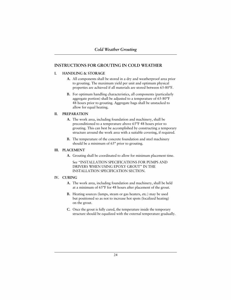
24
INSTRUCTIONS FOR GROUTING IN COLD WEATHER
I. HANDLING & STORAGE
A. All components shall be stored in a dry and weatherproof area priorto grouting. The maximum yield per unit and optimum physicalproperties are achieved if all materials are stored between 65-80°F.
B. For optimum handling characteristics, all components (particularlyaggregate portion) shall be adjusted to a temperature of 65-80°F 48 hours prior to grouting. Aggregate bags shall be unstacked toallow for equal heating.
II. PREPARATION
A. The work area, including foundation and machinery, shall bepreconditioned to a temperature above 65°F 48 hours prior togrouting. This can best be accomplished by constructing a temporarystructure around the work area with a suitable covering, if required.
B. The temperature of the concrete foundation and steel machineryshould be a minimum of 65° prior to grouting.
III. PLACEMENT
A. Grouting shall be coordinated to allow for minimum placement time.
See “INSTALLATION SPECIFICATIONS FOR PUMPS ANDDRIVERS WHEN USING EPOXY GROUT” IN THEINSTALLATION SPECIFICATION SECTION.
IV. CURING
A. The work area, including foundation and machinery, shall be held at a minimum of 65°F for 48 hours after placement of the grout.
B. Heating sources (lamps, steam or gas heaters, etc.) may be used but positioned so as not to increase hot spots (localized heating) on the grout.
C. Once the grout is fully cured, the temperature inside the temporarystructure should be equalized with the external temperature gradually.
Cold Weather Grouting

ESCOWELD ESCOWELD ESCOWELD ESCOWELD EPOXY GROUT SYSTEMS EPOXY GROUT SYSTEMS EPOXY GROUT SYSTEMS EPOXY GROUT SYSTEMS Hot Weather Grouting
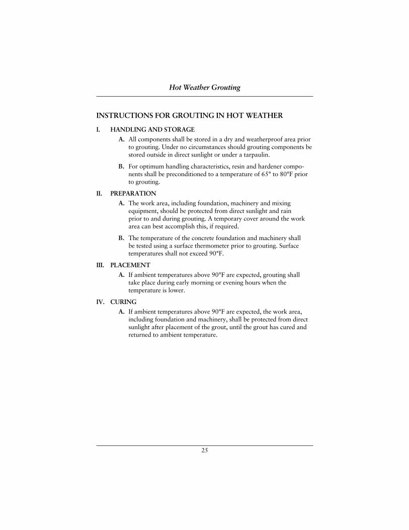
25
INSTRUCTIONS FOR GROUTING IN HOT WEATHER
I. HANDLING AND STORAGE
A. All components shall be stored in a dry and weatherproof area priorto grouting. Under no circumstances should grouting components bestored outside in direct sunlight or under a tarpaulin.
B. For optimum handling characteristics, resin and hardener compo-nents shall be preconditioned to a temperature of 65° to 80°F priorto grouting.
II. PREPARATION
A. The work area, including foundation, machinery and mixing equipment, should be protected from direct sunlight and rain prior to and during grouting. A temporary cover around the workarea can best accomplish this, if required.
B. The temperature of the concrete foundation and machinery shall be tested using a surface thermometer prior to grouting. Surfacetemperatures shall not exceed 90°F.
III. PLACEMENT
A. If ambient temperatures above 90°F are expected, grouting shall take place during early morning or evening hours when thetemperature is lower.
IV. CURING
A. If ambient temperatures above 90°F are expected, the work area,including foundation and machinery, shall be protected from directsunlight after placement of the grout, until the grout has cured andreturned to ambient temperature.
Hot Weather Grouting

ESCOWELD ESCOWELD ESCOWELD ESCOWELD EPOXY GROUT SYSTEMS EPOXY GROUT SYSTEMS EPOXY GROUT SYSTEMS EPOXY GROUT SYSTEMS Installation Specification For Pumps & Drivers when using Epoxy Grouts
27
1.0 Scope ........................................................................................................28
2.0 General .....................................................................................................28
3.0 Material and Testing Requirements ....................................................29-31
4.0 Baseplate/Soleplate Design ..................................................................32-33
5.0 Equipment and Material Storage ........................................................34-35
6.0 Preparation of Foundation and Anchor Bolts .....................................35-37
7.0 Baseplate/Soleplate Preparation...........................................................37-38
8.0 Installation of Baseplate/Soleplate on Foundation...............................39-40
9.0 Forming the Foundation .....................................................................41-42
10.0 Epoxy Grout Installation.....................................................................42-45
11.0 After the Grout Has Cured .................................................................45-46
12.0 Clean-up of Equipment and Personnel .....................................................46
13.0 Testing of Epoxy Grout Samples ..............................................................47
14.0 Records.....................................................................................................47
Baseplate/Soleplate Checklist....................................................................48
Foundation Preparation Checklist ............................................................49
Baseplate Preparation Checklist ...............................................................50
Installation of Baseplate/Soleplate on the Foundation Checklist ..............51
Forming the Foundation Checklist ...........................................................52
Epoxy Grout Installation
Material Checklist...........................................................................53
Equipment Checklist .......................................................................54
Grout Placement Checklist ........................................................55-56
Table of Contents
28
1.0 SCOPEThis specification governs the minimum technical requirements of epoxy groutsand is intended for the grouting of pumps and drivers on concrete foundationsfor both baseplate and/or soleplate mounted equipment.
2.0 GENERAL2.1 The CONTRACTOR shall install pumps and drivers per this specifi-
cation, but it should be noted that the CONTRACTOR shall also followany particular instructions provided by the equipment manufacturers.Conflicts shall be resolved by the Machinery Engineer.
2.2 This specification together with the equipment installation instructionscovers the recommended method for the epoxy grouting of all equip-ment requiring critical alignment and/or in a chemical environment. Any ANSI pump rotating over 1750 RPM shall be grouted with epoxygrout. The epoxy grout shall be applied in accordance with the groutmanufacturer’s procedures.
2.3 A grouting performance demonstration/training session will be con-ducted by the grout manufacturer’s representative prior to foundationand baseplate preparation and the first epoxy grouting on site. Thistraining session will prequalify the placement personnel, demonstrate the proper preparation and installation methods used and ensure that the epoxy grouting material available will meet the manufacturer’sspecified grout installation and strength requirements.
2.4 An asterisk (*) indicating inspection and approval by the MachineryEngineer is required.
2.5 Vertical pumps shall be installed in accordance with the applicable partsof this specification, unless otherwise specified.
Installation Specification for Pumps and Drivers When Using Epoxy Grouts
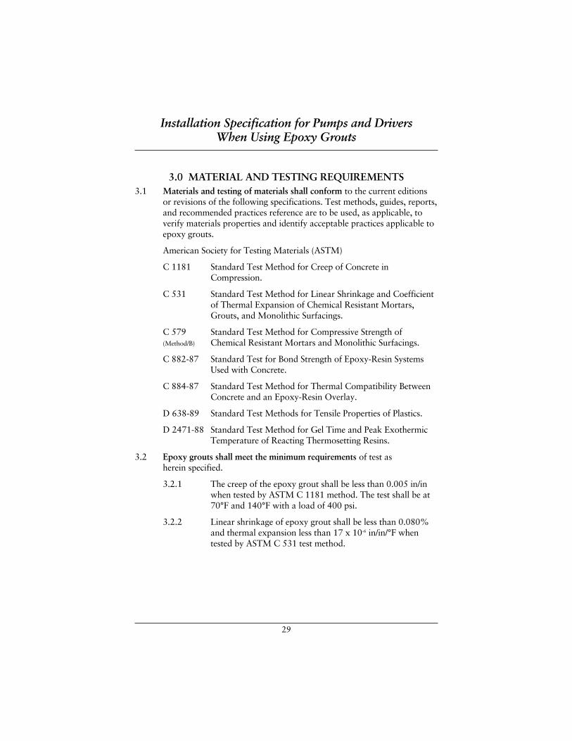
29
3.0 MATERIAL AND TESTING REQUIREMENTS3.1 Materials and testing of materials shall conform to the current editions
or revisions of the following specifications. Test methods, guides, reports,and recommended practices reference are to be used, as applicable, toverify materials properties and identify acceptable practices applicable toepoxy grouts.
American Society for Testing Materials (ASTM)
C 1181 Standard Test Method for Creep of Concrete inCompression.
C 531 Standard Test Method for Linear Shrinkage and Coefficientof Thermal Expansion of Chemical Resistant Mortars,Grouts, and Monolithic Surfacings.
C 579 Standard Test Method for Compressive Strength of(Method/B) Chemical Resistant Mortars and Monolithic Surfacings.
C 882-87 Standard Test for Bond Strength of Epoxy-Resin SystemsUsed with Concrete.
C 884-87 Standard Test Method for Thermal Compatibility BetweenConcrete and an Epoxy-Resin Overlay.
D 638-89 Standard Test Methods for Tensile Properties of Plastics.
D 2471-88 Standard Test Method for Gel Time and Peak ExothermicTemperature of Reacting Thermosetting Resins.
3.2 Epoxy grouts shall meet the minimum requirements of test as herein specified.
3.2.1 The creep of the epoxy grout shall be less than 0.005 in/inwhen tested by ASTM C 1181 method. The test shall be at70°F and 140°F with a load of 400 psi.
3.2.2 Linear shrinkage of epoxy grout shall be less than 0.080%and thermal expansion less than 17 x 10-6 in/in/°F whentested by ASTM C 531 test method.
Installation Specification for Pumps and Drivers When Using Epoxy Grouts
30
3.0 MATERIAL AND TESTING REQUIREMENTS (continued)
3.2.3 The compressive strength of epoxy grout shall be aminimum of 12,000 psi in 7 days when tested by ASTM C 579 method 8, modified.
3.2.4 Bond strength of epoxy grout to portland concrete shall begreater than the concrete itself using ASTM C 882 test method.
3.2.5 Epoxy grout shall pass the thermal compatibility test whenoverlayed on portland cement concrete using test methodASTM C 884.
3.2.6 Tensile strength and modulus of elasticity shall be deter-mined by ASTM D 638. The tensile strength shall not be less than 1700 PSI and the modulus of elasticity shall not be less than 1.8 x 10⁶ psi.
3.2.7 Gel time and peak exothermic temperature of epoxy groutsshall be determined by ASTM D 2471. Peak exothermic tem-perature shall not exceed 110°F when a specimen 6" diameterx 12" high is used. Gel time shall be a least 150 minutes.
3.2.8 The grout shall be suitable for supporting precisionmachinery subject to high impact and shock loading inindustrial environments while exposed to elevatedtemperature as high as 150°F, with a load of 1200 PSI.
3.3 The Epoxy Primer shall be a lead free, chrome free, rust inhibitive, twocomponent epoxy primer specifically designed for use on metal substratesand in conjunction with epoxy grout. ITW Philadelphia Resins RustInhibitive Primer is recommended, however check with your localEscoweld representative for a list of approved primers.
3.3.1 Surface Preparation: All surfaces must be dry, clean and freeof all previous coatings, rust and surface contamination.Minimum surface preparation is abrasive blast to Com-mercial Grade SSPC-SP 6. Blasted surfaces must be coatedwithin 8 hours. Prior to blast cleaning, remove all depositsof oil or grease using Solvent Clean Method SSPC-SP 1.
3.3.2 Recommended System: ITW Philadelphia Resins RustInhibitive Primer is the recommended primer for machinerybaseplates when using Escoweld® epoxy systems.
Installation Specification for Pumps and Drivers When Using Epoxy Grouts
31
3.0 MATERIAL AND TESTING REQUIREMENTS (continued)
3.3.3 Mixing and Application: Pour one part resin (dark gray)and one part hardener (cream) into a container and powermix for 2-3 minutes to ensure that all pigment is completelydispersed. Allow 30 minutes “sweat-in-time” in coveredcontainer before applying. All material and surfacetemperature must be at least 55°F (13°C) and air temper-ature must be 5°F (3°C) above dew point. Relative humiditymust be less than 85%. Application can be done with brush,roller or spray. For spraying, reduce by adding 1 pint of PRT-61 reducer per gallon of catalyzed epoxy after“sweat-ing” (recommended airless spray equipment includesDevilbiss JGA-Gun, Graco Golden Gun, etc. Tip size—0.015 to 0.021" at approximately 2500 psi). Clean allequipment with Escoweld® PRT-61.
3.3.4 Technical Information:
Color: Dark Gray
Gloss: Satin Sheen
Volume Solids: 55%
Coverage: 250 to 300 sq.ft./gal. @ 3 to 3.7 mil DFT (23.2 to 27.9 M2/gal. @ 75 to 95 microns DFT)
Packaging: 2-gal and 10-gal units.
Serviceability: Recoat-8 hr. min.@ 72°F @ 50% RHFull Cure-5 days @ 72°F @ 50% RH
Pot Life: 8 Hr. @ 72°F (22°C)
Flash Point: 80°F TCC (27°C)
Viscosity: 70-80 Krebs Units
Reducer: ESCOWELD® PRT-61
Service Temperature: 200°F (90°C) Dry Heat Resistance
Installation Specification for Pumps and Drivers When Using Epoxy Grouts
32
4.0 BASEPLATE/SOLEPLATE DESIGN4.1 All baseplates and soleplates, where applicable, shall be fabricated
in accordance with current API or ANSI standards as a minimum.
4.2 The baseplate shall be fitted with one 6" grout fill hole uniformlydistributed for every 9 square feet of baseplate surface and/or persubdivided section. Each grout hole shall have a one inch cylindricalraised lip to facilitate grout filling.
4.3 Vent holes 3/8" size shall be provided for each bulkhead compartment at all corners, high points and perimeter edges of the bulkhead. Perimetervent holes in the baseplate shall be on 18" centers maximum spacing.Any angle iron or “C” channel added for stiffeners will require ventholes on both sides.
4.4 Vertical jacking bolts 1/2" diameter minimum shall be provided aroundthe baseplate mounting flange perimeter at each anchor bolt location tofacilitate alignment of the baseplate in the vertical direction.
4.5 Machined mounting surfaces for the pump and driver shall havehorizontal positioning bolts 1/2" diameter minimum. Provide eight (8) alignment positioning jack bolts for the driver.
4.6 The horizontal positioning bolts for the machined mounting surfacesshall be bolted on the side of the machined surfaces and not welded to the machined surfaces or the baseplate.
4.7 All welding on the baseplate shall be completed and stress relieved prior to machining pump and driver mounting surfaces.
4.8 No welding shall be allowed on the machined surfaces to preventwarping. In addition, the bolted on positioning bolts allow for fieldmachining if required.
4.9 Machined mounting surface shall be coplanar to .002". All baseplatewelds shall be continuous in any location where the weld may beexposed to the chemical environment. All welds shall be crack free.
4.10 Machined mounting surfaces shall extend two (2) inches beyond pumpand driver feet on all sides.
4.11 Provide 1/8" minimum shim adjustment under driver feet for alignment.
Installation Specification for Pumps and Drivers When Using Epoxy Grouts
33
4.0 BASEPLATE/SOLEPLATE DESIGN (continued)
4.12 The baseplate shall be designed with four (4) lifting lugs, one at each corner,designed to lift the weight of the complete baseplate, pump and driver.
4.13 Anchor bolt holes shall be 1/4" larger on the diameter than the anchor bolts.
4.14 A detailed certified drawing of the baseplate shall be provided forapproval to the owner’s engineer. This drawing shall show the locationof the baseplate reinforcement, the areas coated with the groutmanufacturer’s approved primer, complete dimensions of the baseplateand the dimensions of features such as: vertical jacking bolts, drain lip,drain, grout hole dimensions, rounded corners and air vent holes.
4.15 All structural steel details (reinforcements, stiffeners, etc.) shall be shownon the certified submittal drawings. Any feature that will facilitate theengineer’s job during the installation phase shall be shown.
4.16 All bulkhead cross bracing on the underside of the baseplate shall have a 2 inch by 6 inch opening to allow for grout flow from bulkhead tobulkhead.
4.17 Radius all corners of baseplate flanges a minimum of 1/2". All surfaceswhich will be in contact with the epoxy should be rounded to eliminatestress risers.
4.18 The baseplate underside shall be sandblasted to a minimum of CommercialGrade SSPC-SP 6. Blasted surfaces must be coated within 8 hours with a coat of ITW Philadelphia Resins Rust Inhibitive Primer to 3.0-5.0 milsDFT (Dry Film Thickness).
4.19 Typical shop primers shall not be used to coat the baseplate underside or any surface that will be bonded to the epoxy grout. Alkyd or highbuild epoxy coatings or primers are typically not acceptable due to their low tensile bond strength. Consult owner’s representative and grout manufacturer’s representative.
Installation Specification for Pumps and Drivers When Using Epoxy Grouts
* indicating inspection and approval by the Machinery Engineer is required.
34
5.0 EQUIPMENT AND MATERIAL STORAGE5.1 The Contractor’s Mechanical Inspector and the Customer’s Inspector
shall check the pre-grouting items prior to epoxy grout installation andverify acceptance by signing the appropriate area on the check lists ascontained in section 12.0 RECORDS of this specification. When therequired check lists are completed and all signatures are obtained, theContractor’s Inspector shall attach a grout release tag on the equipmentto indicate its release for epoxy grouting. Grouting will be completedwithin 24 hours or the baseplate alignment will need to be rechecked.
5.2* All epoxy grout materials shall be stored indoors and kept dry, free of moisture in its original shipping containers.
5.3* Storage temperature shall be maintained between 50°F and 80°F.Grouting materials shall be kept between these temperatures for aminimum of forty-eight (48) hours prior to mixing and placement.
5.4* The epoxy grout aggregate shall be stored inside and kept dry. To testmoisture content of aggregate, squeeze it by hand and if it balls up, it hastoo much moisture in it. The grout manufacturer’s representative shouldbe consulted prior to mixing if too much moisture is present. Deviationfrom this criterion requires approval from the Customer’s Representative.
5.5 In hot weather, due to the accelerated rate of curing at high temperature,the shading of the foundation from summer sunlight for at least 48 hoursbefore and 24 hours after grouting is required. The epoxy liquid andaggregate should be preconditioned to 70-80°F before mixing andplacement. In hot summer weather, it is preferable to place the groutduring the morning, so that the initial cure will occur during the coolermorning hours.
5.6 In cold weather, the grouting materials (including the aggregate) must be stored in unopened containers, dry, at a temperature of 70-80°F for a time long enough for all components to equalize in temperature. Whenthe ambient temperature or the equipment and foundation temperature is below 65°F, the grout manufacturer should be consulted before mixingand placing the grout. The Machinery Engineer must approve anyprocedure for grouting below 65°F.
Installation Specification for Pumps and Drivers When Using Epoxy Grouts
* indicating inspection and approval by the Machinery Engineer is required.
35
5.0 EQUIPMENT AND MATERIAL STORAGE (continued)
5.7 For ambient temperatures below 65°F, fabricate a temporary shelteraround the baseplate or soleplate to be grouted and prewarm thebaseplate or soleplate and foundation for at least 48 hours to 65°Fminimum (i.e. the entire area around concrete must be brought to 65°Ffor 24 hours to ensure concrete is uniformly warm). When prewarmingthe installation, use convection-type space heating equipment and becareful not to overheat localized areas. Do not use radiant heating oropen steam. Radiant heating warms the grout upper surface more thanthe lower surface.
5.8 Epoxy grout has a limited shelf life. Check the grout manufacturer’sinstructions prior to use. Escoweld® epoxy grouts have a shelf life of two (2) years or more depending on storage conditions.
5.9 WARNING: Material should be kept away from open flame, high heatsources, or sparks. It should be mixed in a well-ventilated area. Workmenshould wear eye protection, gloves, and protective clothing at all timesduring mixing and placing of grout and aggregate. A dust mask isrecommended when adding the aggregate to the mixer.
6.0 PREPARATION OF FOUNDATION AND ANCHOR BOLTS6.1 Plastic anchor bolt sleeves shall be used on all anchor bolts. Note: Sleeves
are not intended to encourage careless positioning of the anchor bolts.The anchor bolt sleeve’s primary function is to prevent bonding of thegrout to the anchor bolt and allow stretch in the anchor bolt during finaltorque to achieve design clamping force. The sleeve’s secondary functionis to allow for slight errors in baseplate hole layouts and small shifting ofthe anchor bolts during the concrete placement.
Installation Specification for Pumps and Drivers When Using Epoxy Grouts
36
6.0 PREPARATION OF FOUNDATION AND ANCHOR BOLTS (continued)
6.2 Prior to concrete placement, the anchor bolts should be:
1. Accurately set according to foundation drawings and firmly secured toprevent shifting during concrete placement.
2. Dimensionally checked against the foundation drawings for properlength, diameter, thread length, etc.
3. Checked for proper thread projection.
4. Protected in the thread area by heavily greasing or waxing the threadswith paste wax and wrapping with plastic sheeting. The protectivewrapping must be firmly secured with tie wires.
6.3* Baseplate or soleplates shall not be placed on foundations until theconcrete has had time to cure. The concrete must be at least 28 days oldprior to surface preparation or grouting, and have a minimum of 3,000psi compressive strength.
6.4* After the concrete is fully cured, the foundation should be chippedapproximately 1/2" – 3/4", to remove all laitance and defective or weakconcrete. A light duty, hand held pneumatic chipper with a chisel typetool shall be used for chipping the foundation. Sandblast, bush-hammeror needle gun preparation of concrete surfaces to be grouted are notacceptable. Do not use jack hammers with sharp pointed chisels. Theamount of concrete removed shall be such that the final baseplate orsoleplate elevation results in 2" to 3" of grout between the surface of thefoundation and lower baseplate flange or the underside of the soleplate.
6.5* Chamfer all the foundation edges 2" to 4" at a 45° angle, in order toremove stress concentration. Remove all dust, dirt, chips, oil, water, andany other contaminants and cover the foundation.
Installation Specification for Pumps and Drivers When Using Epoxy Grouts
* indicating inspection and approval by the Machinery Engineer is required.
37
6.0 PREPARATION OF FOUNDATION AND ANCHOR BOLTS (continued)
6.6* After the foundation has been chipped and if epoxy grout placement does not occur within eight (8) hours the foundation should be covered to preventit from becoming contaminated or wet.
6.7* Do Not Remove the tops of the plastic anchor bolt sleeves. Ensure thatthe sleeves are secure. Check the condition of the bolt threads and repairas necessary. Refer to paragraph 8.3 and 8.4 of this specification forprotection of anchor bolt sleeve.
7.0 BASEPLATE/SOLEPLATE PREPARATION7.1 All drivers and driven equipment shall be removed from the baseplates
prior to baseplate inspection and grouting. Drivers and driven equipmentshall be reinstalled after the baseplate has been grouted and after thegrout has cured for a minimum of 24 hours.
7.2 Check to be sure the baseplates or soleplates provided by equipmentsupplier are manufactured in accordance with engineering specifications.The Contractor must inspect and verify that the baseplate or soleplate isin accordance with the customer’s specifications. If any deviations fromthese specifications are identified, the Contractor shall notify theCustomer’s Representative prior to proceeding.
7.3 When the machine is received on site, the baseplate’s epoxy coatingshould be inspected for defects (i.e., chips, gouges, etc.) and repaired per the grout manufacturer’s recommendation.
Installation Specification for Pumps and Drivers When Using Epoxy Grouts
* indicating inspection and approval by the Machinery Engineer is required.
38
7.0 BASEPLATE/SOLEPLATE PREPARATION (continued)
7.4* Baseplate or soleplate surfaces (except for mounting pads and threadedholes, but including the outside edge) which will be in contact with theepoxy grout, shall have been previously coated with an epoxy primer (ITW Philadelphia Resins Rust Inhibitive Primer) as recommended by the epoxy grout supplier. If not coated, the surface shall be sandblasted to SSPC-SP 6 (1 to 1.5 mil anchor profile minimum) and coated with onecoat of ITW Philadelphia Resins Rust Inhibitive Primer.
7.5* All baseplates shall be provided with at least one grout opening not lessthan 4" diameter in each bulkhead section. Vent holes (3/8" size) shall beprovided for each bulkhead compartment at all corners, high points andedges of bulkheads. Air vent holes will also be required along both sidesof any stiffener channels added to the baseplate underside. All otherareas shall have air vent holes on 18" centers. For dropped-center-troughbaseplates, the holes shall be in the high section adjacent to the trough.Grout holes in the drip pan area shall have 1/2 inch raised lip edges.
7.6* Jacking screws (1/2" minimum dia.) shall be provided around thebaseplate mounting flanges perimeter at each anchor bolt location tofacilitate vertical alignment of the baseplate.
7.7* All corners of baseplates or soleplates shall be rounded to at least 1/2"radius to prevent stress risers which can create stress cracking in the grout.
7.8* All cross bracing on underside of baseplate shall have 2" x 6" minimumopening to allow for grout flow.
7.9* All surfaces of the baseplate or soleplate (including the outside edges),which will be in direct contact with the grout, shall be made free of alloil, grease and rust.
7.10* If the epoxy-coated baseplate is not grouted within thirty (30) days (priorto placement on the foundation and placement of the grout) the epoxyprimed surfaces on the baseplate shall be roughened-up with a wirebrush to remove the bloom or shine. All dust produced by brushing orsanding shall be wiped off using a water-dampened cloth. These surfacesshall be air-dried prior to placement of grout.
Installation Specification for Pumps and Drivers When Using Epoxy Grouts
* indicating inspection and approval by the Machinery Engineer is required.
39
8.0 INSTALLATION OF BASEPLATE/SOLEPLATE ON FOUNDATION
8.1* Surfaces of the concrete and baseplate which will come in contact withthe epoxy grout shall be clean and free of all oil, rust, scale, and dirt.This cleaning shall be done immediately prior to placement of thebaseplate on the foundation. If the baseplate has been primed with ITW Philadelphia Resins Rust Inhibitive Primer, a solvent wash or waterwash is all that is required. Any contaminated surfaces must be chippedto clean (white) concrete.
8.2* Foundation bolt threads shall be examined for stripped or damagedthreads. These threads shall be rechased to clean up or the foundationbolts replaced if necessary. The foundation bolts and their threads shallbe protected during the placement of the baseplate, leveling and groutingoperation.
8.3* If the foundation anchor bolt sleeves tops have been removed, the sleevesshall be filled with a non-bonding, pliable material (i.e., wax, siliconerubber, ITW Philadelphia Resins Expansion Joint Compound, etc.) and sealed. It is imperative that epoxy grout not be allowed to fill theanchor bolt sleeve.
8.4* Foundation bolts shall be wrapped with one (1) layer of Dux-Seal overtheir entire exposed length to prevent direct contact between the epoxygrout and anchor bolt.
8.5* The vertical jacking bolts shall be coated with a nonbonding lubricant to allow the jacking bolts to be backed-out of the grout after the grouthas cured. Do not use paste wax to lubricate the vertical jacking bolts.
8.6* Install greased coupling guard bolts into coupling guard bolt holes on the baseplate to prevent grout from filling these holes (also pipe supportsholes, etc.). These bolts shall be installed to their full depth to allowthread embedment in the grout.
Installation Specification for Pumps and Drivers When Using Epoxy Grouts
* indicating inspection and approval by the Machinery Engineer is required.
40
8.0 INSTALLATION OF BASEPLATE/SOLEPLATE ON FOUNDATION (continued)
8.7* Position the baseplate or soleplate on the prepared foundation at the correctelevation, supported on the leveling jack bolts. Circular plates cut from 3"diameter steel bar stock, 1/2" thick, with rounded edges, should be usedunder each leveling jack bolts to prevent the leveling jack bolts fromdigging into the concrete and altering the levels. These circular metal plateswill remain in the grout. For baseplate installation the vertical jackingscrew pads do not have to be leveled and grouted. It is suggested that thepads be leveled and grouted for large soleplate installations. If shim packsare used for leveling, the first shim pad should be leveled and grouted. Wax,mask off, or grease areas which require protection from grout splatter.
8.8* According to Perry C. Monroe, “Baseplate leveling begins with the pumpand driver removed, after checking the pump suction and discharge flangesfor the proper location and elevation. Piping should not be attached to thepump until the baseplate has been leveled, grouted and the driver/pumpaligned. The use of a Starrett 98 machinists level, mounted on the machinedsurfaces for the driver, is recommended. The Jack screws and anchor boltsare adjusted until a level of 0.0005 in./ft. is obtained in two directions, 90 degrees apart. The machined surfaces for the pump receive the sametreatment, with a maximum elevation variation across the length of thebaseplate of 0.010 inch. A precision straight edge should be used across themounting surfaces to check for coplanarity. The mounting surfaces shouldbe coplanar within 0.002 inch.”
8.9* “If the baseplate is long (over 15 ft.) an optical level, similar to the K&EModel 71-3015, might be used to speed up the leveling operation”1
8.10 If shims or wedges are used for leveling, they shall be blocked out to allow for their removal after the grout has cured.
Installation Specification for Pumps and Drivers When Using Epoxy Grouts
* indicating inspection and approval by the Machinery Engineer is required. 1 Perry C. Monroe, Jr. Pump Baseplate Installation and Epoxy Grout, 5th International PumpUsers Symposium Proceedings, May 1988, Monroe Technical Services, Houston, Texas.
41
9.0 FORMING THE FOUNDATION9.1 Grout forms shall be built of a minimum of 3/4" thick plywood and shall
be securely braced (minimum brace size to be 2" x 4").
9.2 Forms shall provide a minimum of 2" hydrostatic head above the finalelevation of the grout, to assist in flow during installation.
9.3 Epoxy grout forms must be coated with three coats of hardwood pastewax on all areas that will come in contact with the grout to keep thegrout from bonding to the forms. Forms should be waxed beforeinstallation, to prevent accidental application of wax to surfaces wherethe grout is to bond. To permit easy clean-up, wax or cover all surfaceswhere grout may splash. Allow time for the wax to penetrate into thewood before applying the next coat.
9.4* Before any forms are installed, all concrete surfaces that will contactepoxy grout should be free of any foreign material, such as oil, sand,water, grease, etc. (anything that could have an adverse effect on anybonding surfaces).
9.5 Forms shall be liquid-tight, because epoxy grout will flow through eventhe smallest opening. Any open spaces or cracks in forms, or at the jointbetween forms and the foundation, shall be sealed off, using RTVsealant. The outside top edges of the grout shall be chamfered at 45°, as well as the vertical corners.
9.6* The 45° chamfer strip shall be located at the final elevation of the grout.The final elevation of the grout on baseplates with I-beam or C-channelsupport shall be at the top of the lower support flange. The top of thegrout, on baseplates with solid sides and soleplates, shall be 1.0 inchabove the bottom of the baseplate or the underside of the soleplate. Thegrout’s final elevation should not be so high as to bond the anchor boltnut and washer.
9.7* Foundation anchor bolt sleeves shall be filled with a non-bonding, pliablematerial, such as Expansion Joint Compound. It is imperative that epoxygrout not be allowed to fill the anchor bolt sleeve.
Installation Specification for Pumps and Drivers When Using Epoxy Grouts
* indicating inspection and approval by the Machinery Engineer is required.
42
9.0 FORMING THE FOUNDATION (continued)
9.8* Duxseal shall be placed around the exposed threads of anchor bolts, toprevent direct contact between the epoxy grout and anchor bolts. Installlubricated bolts into any threaded hole in the baseplate, to prevent groutfrom filling these holes. These bolts should be totally engaged to providea space under the baseplate such that when the bolts are later engaged,the bolt will not jack against the grout and jack the baseplate up. (Alsopipe support holes, etc.)
9.9* The foundation should be protected from rain with a tarp since it isimportant that the foundation be clean and dry at the time of grouting.
10.0 EPOXY GROUT INSTALLATION10.1 Escoweld® 7505E with 7530 aggregate epoxy type grout shall be used for
the installation of all pumps and drivers. The Contractor shall follow theinstruction procedures in Paragraph 7.1.1 through 7.1.13. The epoxy groutmanufacturer’s requirements and instructions shall be strictly followed.
10.2 Rope off the work area and move all grouting material and tools insidethe roped off area just before the job starts. When started, it should becompleted without stopping and tools cleaned with medium pressurewater immediately upon completion. Water from a fire monitor ormedium pressure plant water cleans the mixer and tools.
10.3 Timing and proper mixing are the secrets to successful grouting. Thegrout supplier’s instructions must be followed implicitly. Before mixingthe components together, everything else should be ready—surfacescleaned and dry, forms completed and sealed, rags, cleaning solventsavailable, adequate manpower and grout (an additional 25% in excess of the calculated requirement of grout should be in the area).
10.4 Epoxy grout can be manually mixed in a wheelbarrow, mortar box, ormechanical mortar mixer. For small pours, 5 units or less, use a cleanwheelbarrow or mortar box and a mortar hoe. Over mixing and/or violentmixing whips air into the grout and results in voids under the baseplate.
Installation Specification for Pumps and Drivers When Using Epoxy Grouts
* indicating inspection and approval by the Machinery Engineer is required.
43
10.0 EPOXY GROUT INSTALLATION (continued)
10.5 A mortar mixer is the preferred method for mixing. If used, the mortarmixer speed should not exceed 25 RPM. The mortar mixer should have aclutch to disengage the mixer blades to prevent over mixing the grout.
NOTE: DO NOT MIX PARTIAL UNITS.
10.6 The average epoxy working time is approximately two (2) hoursdepending on the ambient temperature. For specific times consult withthe epoxy grout manufacturer.
10.7 The epoxy resin and hardener shall be mixed with a Jiffy Mixer per thegrout manufacturer’s recommendations (typical three [3] minutes). Afterthe epoxy liquid and hardener have been mixed, the mixed solution ispoured into the hardener can and stirred for a minute to activate theresidue hardener in the can. All the liquid is then poured into the mixer.
10.8 Aggregate is slowly added to the mixer one bag at a time. The groutshould be mixed only long enough to wet out all the aggregate. ForEscoweld® 7530 aggregate system, mix an additional 1-1/2 minutes toactivate the flow enhancement properties. Stop the mixer blades fromrotating if the grout crew is not ready to place the wetted material. It is a requirement that the mortar mixer have a clutch to disengage the rotating paddles when required.
10.9 Epoxy grout is very viscous; however, it will flow readily, given time and positive hydraulic head. If installing below 70°F ambient temperature,consult grout manufacturer to determine if aggregate adjustment is nec-essary. Generally, it is best to start placing the grout at the center of oneend of the baseplate or soleplate and work toward the ends in such amanner as to force the air out from beneath the baseplate or soleplate and out the vent holes, to eliminate voids.
Installation Specification for Pumps and Drivers When Using Epoxy Grouts
44
10.0 EPOXY GROUT INSTALLATION (continued)
10.10* Placing of the grout is accomplished in a manner which avoids airentrapment and a head box is used to aid in pouring the grout into thegrout holes. The head box provides a hydraulic head to force the grout to the vent holes. When the head box is moved to the next grout hole, a6-inch high stand pipe shall be placed over the grout hole and filled withgrout. These stand pipes provide a continuous hydraulic head to sweepair from under the baseplate to the vent holes. NEVER allow the grout to fall below the baseplate level once the grout has made contact with the baseplate. The use of a head box provides a surge volume for thegrout as well as providing the critical hydraulic head.
10.11* NOTE: No push rods, chains or vibrators should be used to place epoxygrout under baseplates.
10.12 Grouting shall be continuous until the placement of grout is completeunder all sections or compartments of the baseplate. Subsequent batchesof grout should be prepared so as to be ready when the preceding batchhas been placed. The grouting crew should never wait on the mixingoperation. The crew mixing the material should always be ahead of theplacement crew.
10.13* Check the forms frequently for leaks. Leaks do not self seal. Use Duxsealto seal the leaks. If not stopped, they will cause voids.
10.14* After the entire baseplate is full, 6-inch high stand pipes should bemaintained over each grout hole, to continue purging of air. Wipe thepurged grout from the air vent holes continuously until the grout stopsflowing from the holes. When the grout has started to take an initial set(determined by a noticeable increase in temperature and no flow of groutat the vent holes) the stand pipes can be removed and excess groutcleaned from all surfaces.
10.15 A grout sample can be taken for each piece of equipment to be grouted.The sample shall be of sufficient size to yield three (3) 2" x 2" x 2" testsamples and shall be tagged with the equipment number, ambienttemperature at the time of placement. The samples should be testedin accordance with the manufacturer’s recommendations.
Installation Specification for Pumps and Drivers When Using Epoxy Grouts
* indicating inspection and approval by the Machinery Engineer is required.
45
10.0 EPOXY GROUT INSTALLATION (continued)
10.16 Once the epoxy grout cylinder has been completely filled, it should be placednext to the foundation of the equipment being grouted and allowed to curefor 48 hours. After 48 hours, the test cylinder should be sent to an outsidetest facility to be tested per the grout manufacturer’s recommendation.
10.17 Forms may be removed when the epoxy grout is adequately cured. Thisgenerally occurs in approximately 24 hours when the surface becomesfirm and not tacky to the touch. When a low temperature accelerator isused, follow the manufacturer’s instructions to determine the typicalcuring time required.
10.18 Before the driver and driven unit are installed, the baseplate/soleplateshall be checked for voids. All voids shall be repaired before anyequipment is installed. See Escoweld “VOID REPAIR PROCEDURE”.
10.19 If shims or wedges were used to level the baseplate, they shall beremoved prior to torquing the anchor bolts and their voids filled withepoxy grout per the grout manufacturer’s recommendation.
10.20 Drivers and driven equipment shall be re-installed after the baseplate has been grouted and after the grout has cured for a minimum of twenty-four (24) hours.
11.0 AFTER THE GROUT HAS CURED11.1 After the grout has cured, the baseplate (soleplate) shall be checked for
complete grouting by tapping the baseplate with a ball peen hammer. If a void is found based on a “hollow* sound, several holes shall be drilledin the baseplate deck around the periphery of the void and a single holedrilled approximately in the center of the void. The void will be filledwith epoxy grout liquid (ITW Philadelphia Resins Concrete Adhesive or 7505E) without the aggregate; the center hole shall be used to applythe grout and the other holes as air vents.
Installation Specification for Pumps and Drivers When Using Epoxy Grouts
46
11.0 AFTER THE GROUT HAS CURED (continued)
11.2 A grease gun and grease fitting is normally used to inject the grout into the void. When this type of injection is used, install dial indicators to confirm that the epoxy placement is not lifting the baseplate.WARNING, if the void is properly vented, there should be minimalpressure required to fill the void. The grease gun is used only as a meansof placement and should not be used to create pressure. If the baseplate is being lifted, release the pressure and retest the baseplate by tapping todetermine if a void actually exists. When the void has been filled, thegrease fittings shall be removed and all holes dressed smooth. See “VOID REPAIR PROCEDURE”.
11.3 When using jack screws, the jack screw support pads used to level the baseplate will be left in place after grouting.
11.4 The baseplate is to remain supported by the jack screws for 24 hoursbefore removing them. The removal of the jack screws will allow the full equipment weight to be distributed evenly over the grouted area.Jack screw removal time is based on surface temperature of the foun-dation being 75°F or above. The jack screw holes shall be filled withRTV or epoxy after being solvent cleaned to remove any bond breaker.A dial indicator shall be placed on the baseplate frame and coupling to indicate any movement when jack screws are removed.
11.5* The foundation anchor bolts can now be torqued. The frame shall be dial indicated at each anchor bolt and coupling, to determine anymovement during torque.
12.0 CLEAN-UP OF EQUIPMENT AND PERSONNEL12.1 The best cleaning procedure for personnel is soap and water.
12.2 Immediately after grouting is completed all tools and mixing equipmentshall be cleaned using medium pressure water or solvent. The grout man-ufacturer’s representative should be contacted for best clean-up procedure.
12.3 All unused mixed epoxy materials shall be disposed of in accordancewith instructions by the epoxy grout manufacturer.
Installation Specification for Pumps and Drivers When Using Epoxy Grouts
* indicating inspection and approval by the Machinery Engineer is required.
47
13.0 TESTING OF EPOXY GROUT SAMPLES13.1 Grout test samples shall be tested by an outside testing facility per the
grout manufacturer’s recommendation.
14.0 RECORDS14.1 The following constitute records which will be maintained and will
become part of the project records:
Baseplate/soleplate design check list
Foundation preparation check list
Baseplate/soleplate preparation check list
Installation of baseplate/soleplate on foundation check list
Forming the foundation check list
Epoxy grouting installation check list
Installation Specification for Pumps and Drivers When Using Epoxy Grouts

ESCOWELD ESCOWELD ESCOWELD ESCOWELD EPOXY GROUT SYSTEMS EPOXY GROUT SYSTEMS EPOXY GROUT SYSTEMS EPOXY GROUT SYSTEMS Installation Specification Checklist
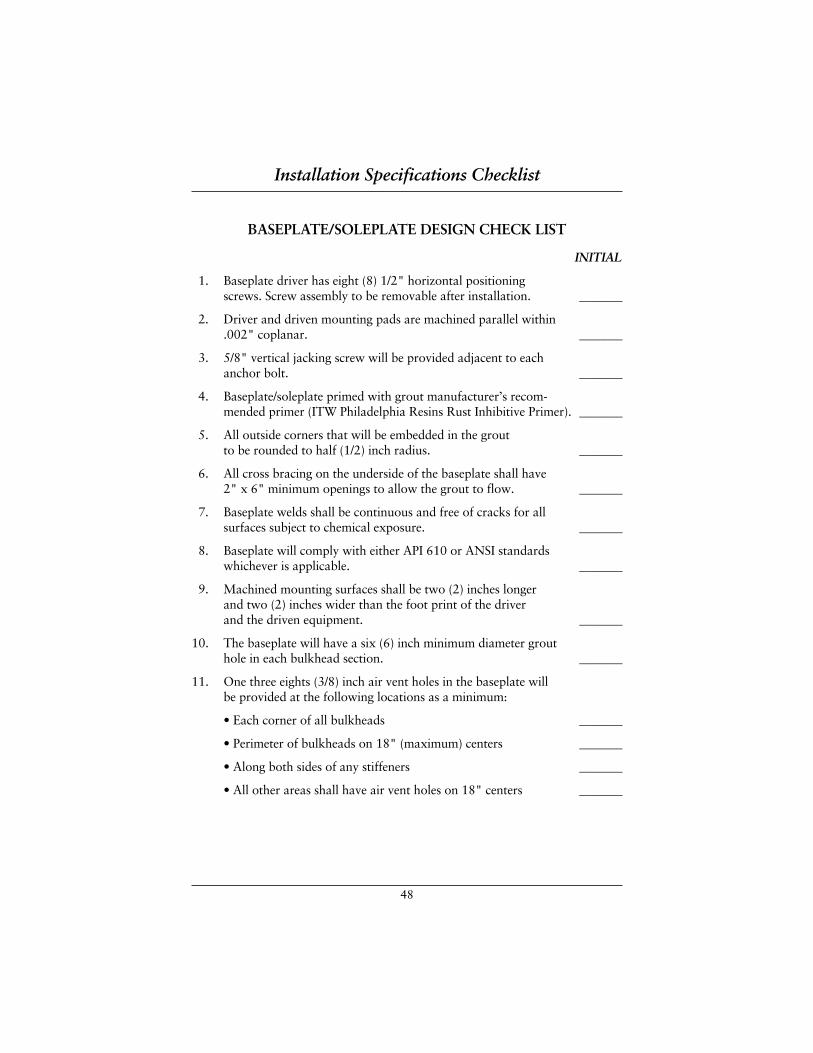
48
BASEPLATE/SOLEPLATE DESIGN CHECK LIST
INITIAL
1. Baseplate driver has eight (8) 1/2" horizontal positioning screws. Screw assembly to be removable after installation. _______
2. Driver and driven mounting pads are machined parallel within .002" coplanar. _______
3. 5/8" vertical jacking screw will be provided adjacent to each anchor bolt. _______
4. Baseplate/soleplate primed with grout manufacturer’s recom-mended primer (ITW Philadelphia Resins Rust Inhibitive Primer). _______
5. All outside corners that will be embedded in the grout to be rounded to half (1/2) inch radius. _______
6. All cross bracing on the underside of the baseplate shall have 2" x 6" minimum openings to allow the grout to flow. _______
7. Baseplate welds shall be continuous and free of cracks for all surfaces subject to chemical exposure. _______
8. Baseplate will comply with either API 610 or ANSI standards whichever is applicable. _______
9. Machined mounting surfaces shall be two (2) inches longer and two (2) inches wider than the foot print of the driver and the driven equipment. _______
10. The baseplate will have a six (6) inch minimum diameter grout hole in each bulkhead section. _______
11. One three eights (3/8) inch air vent holes in the baseplate will be provided at the following locations as a minimum:
• Each corner of all bulkheads _______
• Perimeter of bulkheads on 18" (maximum) centers _______
• Along both sides of any stiffeners _______
• All other areas shall have air vent holes on 18" centers _______
Installation Specifications Checklist
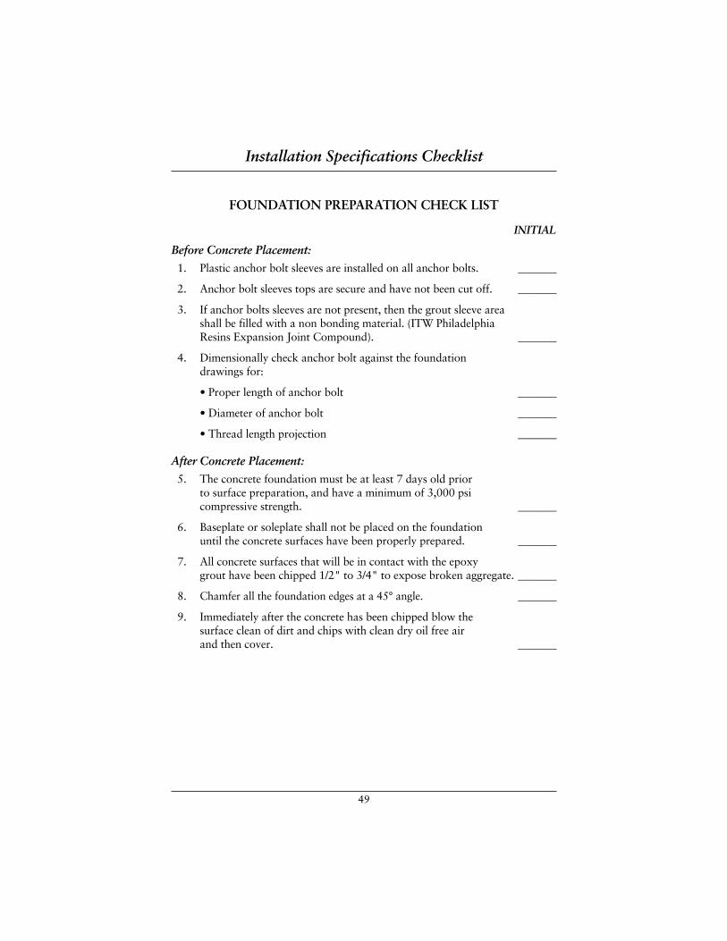
49
FOUNDATION PREPARATION CHECK LIST
INITIAL
Before Concrete Placement:
1. Plastic anchor bolt sleeves are installed on all anchor bolts. _______
2. Anchor bolt sleeves tops are secure and have not been cut off. _______
3. If anchor bolts sleeves are not present, then the grout sleeve area shall be filled with a non bonding material. (ITW Philadelphia Resins Expansion Joint Compound). _______
4. Dimensionally check anchor bolt against the foundation drawings for:
• Proper length of anchor bolt _______
• Diameter of anchor bolt _______
• Thread length projection _______
After Concrete Placement:
5. The concrete foundation must be at least 7 days old prior to surface preparation, and have a minimum of 3,000 psi compressive strength. _______
6. Baseplate or soleplate shall not be placed on the foundation until the concrete surfaces have been properly prepared. _______
7. All concrete surfaces that will be in contact with the epoxy grout have been chipped 1/2" to 3/4" to expose broken aggregate. _______
8. Chamfer all the foundation edges at a 45° angle. _______
9. Immediately after the concrete has been chipped blow the surface clean of dirt and chips with clean dry oil free air and then cover. _______
Installation Specifications Checklist
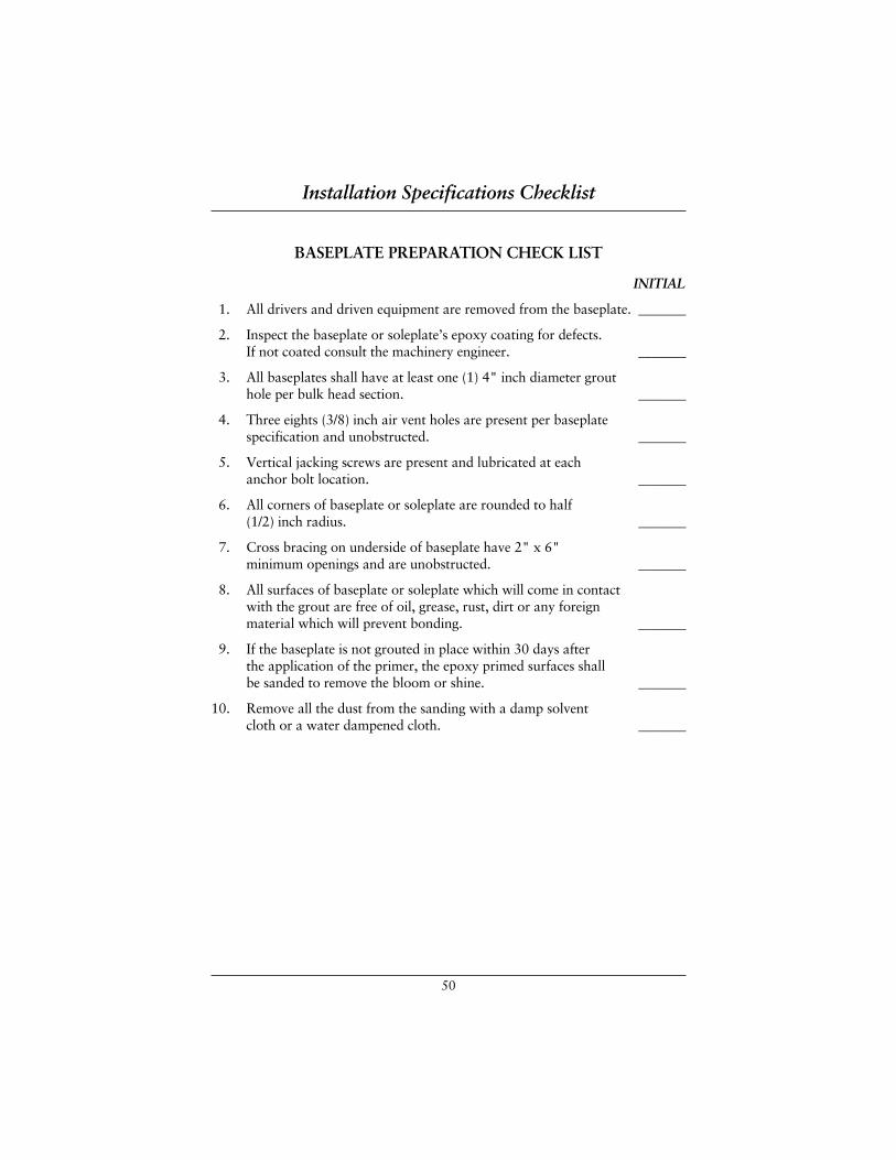
50
BASEPLATE PREPARATION CHECK LIST
INITIAL
1. All drivers and driven equipment are removed from the baseplate. _______
2. Inspect the baseplate or soleplate’s epoxy coating for defects. If not coated consult the machinery engineer. _______
3. All baseplates shall have at least one (1) 4" inch diameter grout hole per bulk head section. _______
4. Three eights (3/8) inch air vent holes are present per baseplate specification and unobstructed. _______
5. Vertical jacking screws are present and lubricated at each anchor bolt location. _______
6. All corners of baseplate or soleplate are rounded to half(1/2) inch radius. _______
7. Cross bracing on underside of baseplate have 2" x 6" minimum openings and are unobstructed. _______
8. All surfaces of baseplate or soleplate which will come in contact with the grout are free of oil, grease, rust, dirt or any foreign material which will prevent bonding. _______
9. If the baseplate is not grouted in place within 30 days after the application of the primer, the epoxy primed surfaces shall be sanded to remove the bloom or shine. _______
10. Remove all the dust from the sanding with a damp solvent cloth or a water dampened cloth. _______
Installation Specifications Checklist
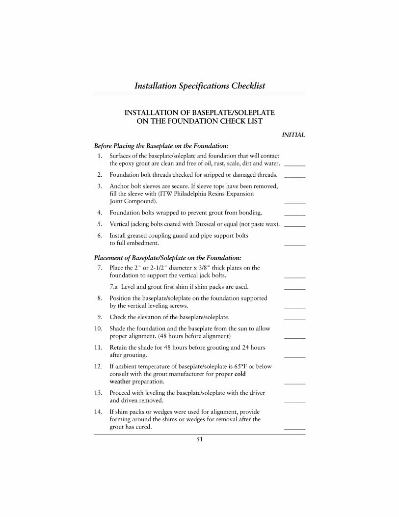
51
INSTALLATION OF BASEPLATE/SOLEPLATE ON THE FOUNDATION CHECK LIST
INITIAL
Before Placing the Baseplate on the Foundation:
1. Surfaces of the baseplate/soleplate and foundation that will contact the epoxy grout are clean and free of oil, rust, scale, dirt and water. _______
2. Foundation bolt threads checked for stripped or damaged threads. _______
3. Anchor bolt sleeves are secure. If sleeve tops have been removed, fill the sleeve with (ITW Philadelphia Resins Expansion Joint Compound). _______
4. Foundation bolts wrapped to prevent grout from bonding. _______
5. Vertical jacking bolts coated with Duxseal or equal (not paste wax). _______
6. Install greased coupling guard and pipe support bolts to full embedment. _______
Placement of Baseplate/Soleplate on the Foundation:
7. Place the 2" or 2-1/2" diameter x 3/8" thick plates on the foundation to support the vertical jack bolts. _______
7.a Level and grout first shim if shim packs are used. _______
8. Position the baseplate/soleplate on the foundation supported by the vertical leveling screws. _______
9. Check the elevation of the baseplate/soleplate. _______
10. Shade the foundation and the baseplate from the sun to allow proper alignment. (48 hours before alignment) _______
11. Retain the shade for 48 hours before grouting and 24 hours after grouting. _______
12. If ambient temperature of baseplate/soleplate is 65°F or below consult with the grout manufacturer for proper cold weather preparation. _______
13. Proceed with leveling the baseplate/soleplate with the driver and driven removed. _______
14. If shim packs or wedges were used for alignment, provide forming around the shims or wedges for removal after the grout has cured. _______
Installation Specifications Checklist
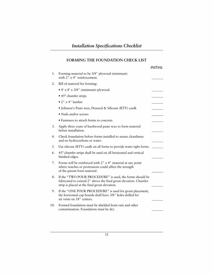
52
FORMING THE FOUNDATION CHECK LIST
INITIAL
1. Forming material to be 3/4" plywood (minimum) with 2" x 4" reinforcement. _______
2. Bill of material for forming:
• 4' x 8' x 3/4" (minimum) plywood _______
• 45° chamfer strips _______
• 2" x 4" lumber _______
• Johnson’s Paste wax, Duxseal & Silicone (RTV) caulk _______
• Nails and/or screws _______
• Fasteners to attach forms to concrete. _______
3. Apply three coats of hardwood paste wax to form material before installation. _______
4. Check foundation before forms installed to assure cleanliness and no hydrocarbons or water. _______
5. Use silicone (RTV) caulk on all forms to provide water tight forms. _______
6. 45° chamfer strips shall be used on all horizontal and vertical finished edges. _______
7. Forms will be reinforced with 2" x 4" material at any point where notches or protrusions could affect the strength of the parent form material. _______
8. If the “TWO POUR PROCEDURE” is used, the forms should befabricated to extend 2" above the final grout elevation. Chamfer strip is placed at the final grout elevation. _______
9. If the “ONE POUR PROCEDURE” is used for grout placement, the horizontal cap boards shall have 3/8" holes drilled for air vents on 18" centers. _______
10. Formed foundation must be shielded from rain and other contamination. Foundation must be dry. _______
Installation Specifications Checklist

53
EPOXY GROUT INSTALLATION CHECK LIST
INITIAL
Material Check List:
1. Calculate cubic foot grout requirement plus 25% more and store close to work area. _______
Length (ft) x width (ft) x depth (ft)
2.4 ft3/unit = Number of 5 bag units
Number of units x 1.25 = Number of units to order.
2. Locate source of medium pressure water to clean mixer and equipment at completion of grouting. _______
3. If water is not available, diesel or solvent (General Epoxy Cleanup Solvent PRT 59) for cleaning. _______
4. Duxseal (5 pounds) to seal forms in case of leak. _______
5. Five (5) gallon bucket of clean water and hand soap for personnel clean up. _______
6. Solvent resistant gloves. _______
7. Dust masks for aggregate mixing crew. _______
8. Ear plugs. _______
9. Safety glasses and/or goggles. _______
10. Protective clothing (paper cover-all). _______
11. Plastic sheeting to protect equipment and area. _______
12. Sand to protect concrete areas from grout spillage. _______
Installation Specifications Checklist
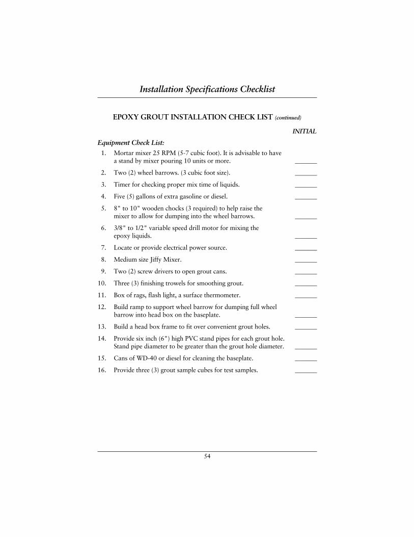
54
EPOXY GROUT INSTALLATION CHECK LIST (continued)
INITIAL
Equipment Check List:
1. Mortar mixer 25 RPM (5-7 cubic foot). It is advisable to have a stand by mixer pouring 10 units or more. _______
2. Two (2) wheel barrows. (3 cubic foot size). _______
3. Timer for checking proper mix time of liquids. _______
4. Five (5) gallons of extra gasoline or diesel. _______
5. 8" to 10" wooden chocks (3 required) to help raise the mixer to allow for dumping into the wheel barrows. _______
6. 3/8" to 1/2" variable speed drill motor for mixing the epoxy liquids. _______
7. Locate or provide electrical power source. _______
8. Medium size Jiffy Mixer. _______
9. Two (2) screw drivers to open grout cans. _______
10. Three (3) finishing trowels for smoothing grout. _______
11. Box of rags, flash light, a surface thermometer. _______
12. Build ramp to support wheel barrow for dumping full wheel barrow into head box on the baseplate. _______
13. Build a head box frame to fit over convenient grout holes. _______
14. Provide six inch (6") high PVC stand pipes for each grout hole. Stand pipe diameter to be greater than the grout hole diameter. _______
15. Cans of WD-40 or diesel for cleaning the baseplate. _______
16. Provide three (3) grout sample cubes for test samples. _______
Installation Specifications Checklist
55
EPOXY GROUT INSTALLATION CHECK LIST (continued)
INITIAL
Grout Placement
1. The epoxy grout representative will conduct a pre-grout school to teach the proper preparation, mixing, and placement procedures for either the “ONE POUR” or the “TWO POUR” procedures. _______
2. If the “ONE POUR PROCEDURE” is used the grout representative will be present for the first pour. _______
3. Organize the material and equipment close to the work area. _______
4. Start the mortar mixer to be sure it runs. _______
5. Clean the mixer of any residue. _______
6. Organize epoxy liquid (parts A & B) and 5 sacks of Escoweld®
7530 aggregate in stacks. _______
7. Open all cans (part A & B) for the number of units estimated to complete the job. _______
8. Make sure all personnel are present, equipped and ready. _______
9. Mix first units of epoxy liquids (parts A & B) for three (3) minutes using the Jiffy mixer and the Escoweld timer. _______
10. After mixing, pour the mixed material into the empty hardener can (part B) to catalyze any residual resin. _______
11. Pour all the mixed liquid into the mixer. _______
12. The first batch of epoxy grout uses 4-1/2 bags of aggregate to wet-out the dry mixer and wheel barrow. All future mixes of grout will be the full 5 bag mix. _______
13. Mix the liquid and aggregate until the aggregate is wet then mix 1-1/2 minutes more. (The Escoweld® 7505E/7530 flow enhancer will convert the material from dry to a very fluid mixture). _______
Installation Specifications Checklist
56
EPOXY GROUT INSTALLATION CHECK LIST (continued)
INITIAL
Grout Placement (continued):
14. Dump the mixture into the wheel barrow and transport to the ramp and head box. _______
15. Capture a grout sample at this time for future testing. _______
16. Continue dumping in the same head box until the grout flows up all the stand pipes. _______
17. If the “ONE POUR PROCEDURE” is used, tape the 3/8" air vent holes in the forms as soon as the grout is seen in the vent holes. _______
18. Do not be concerned about grout flowing from the 3/8" air vent holes in the baseplate. _______
19. When all the stand pipes have about 6" of grout in the pipes and the head box flow has slowed, place a stand pipe over the grout hole in the head box. Remove the excess grout and the head box. All grout holes should have a stand pipe with at least 6" of grout in them. _______
20. Capture the final grout sample for testing. _______
21. Immediately start wiping the 3/8" air vent holes and dumping the excess material into the closest stand pipe. _______
22. Continue wiping the 3/8" air vent holes until the grout stops flowing out of the air vent holes. This should take about 40-45 minutes at 75-80°F. _______
23. Remove the stand pipes and finish cleaning the baseplate. _______
24. Grout forms can be removed 24 hours after grouting. _______
Installation Specifications Checklist

ESCOWELD ESCOWELD ESCOWELD ESCOWELD EPOXY GROUT SYSTEMS EPOXY GROUT SYSTEMS EPOXY GROUT SYSTEMS EPOXY GROUT SYSTEMS Void Repair Procedure
57
VOID REPAIR PROCEDUREVoid repair in either baseplates or soleplates is a time for minimum pressure andmaximum patience. The voids should be carefully “sounded out” with a smallball peen hammer. This small hammer will give a better ring than larger ham-mers, bolt or some other metal object. Carefully scribe the void area so thatproperly positioned vent holes can be located. It will be important to keep thevent holes inside the void area but close to the bond interface. The soundingprocedure should be after the grout has cured for 12 hours minimum.
When tapping the baseplate/soleplate with the ball peen hammer, a definite ring will be heard where a void is present. The areas where the baseplate is infull contact with the grout will have a solid sound like a “lead nickel”. Therewill be other times when the sound will not be so definite. Caution should betaken not to assume there is a void at these locations. Sometimes the crossbracing under the baseplate will give a different sound than in the center of the steel plate. Vertical gusset reinforcement near motor or driven mounts willsometimes ring as you tap the base. Do not confuse these sounds as voids.
IT IS BETTER TO NOT DRILL AND PUMP AN AREA IF YOU ARE NOTSURE THERE IS A VOID. If the grout is properly bonded to the steel plate and the cross members under the baseplate, there is an excellent possibility thatyou will lift the baseplate/soleplate by over pressuring the area and causing morevoids.
DRILLING HOLES:Vent holes should be drilled in the void area and as close to the bonded interfaceas possible. With the vent holes at the perimeter of the void, there is little chanceof pressurizing the void. Injection port holes will be drilled in the center of thevoid. Grease gun zerk fittings are placed in the injection ports to allow forplacing ITW Philadelphia Resins Concrete Adhesive or neat 7505E.
NUMBER OF HOLES:For each injection port, there should be at least three (3) vent holes. Injectionports should not be more than 12" from the vent holes. Because you are alwaysworking “blind” it is imperative to have more than one injection port and ventin any void larger than 12" diameter.
Void Repair Procedure
58
DIAL INDICATING:The coupling should always be dial indicated to be assured there is no movementat the coupling. A dial indicator should be located within 6" of the injectionport. A thin plate of 1/4"-1/2" thick can be lifted when the grout is beingpumped. 3-5 mils positive deflection at the injection port does not mean thecoupling has been affected. The dial indicator at the injection port will indicatethat the rate of injection is too fast or that pressure is developing under the plate.
INJECTION OF REPAIR GROUT LIQUID:During the injection process, there should be no external pressure on thebaseplate. Do not stand or lean on the baseplate.
ITW Philadelphia Resins Concrete Adhesive should be pumped slowly withminimal pressure on the grease gun. The only pressure required should beenough to pump through the gun and zerk fitting. THIS PROCEDURE IS NOTINTENDED TO DEVELOP PRESSURE UNDER TEE BASEPLATE. The onlypurpose for using a grease gun is to provide a method of placing the grout. Overpressuring the void will lift the baseplate and create more voids.
The dial indicator will move when too much pressure is used or the rate ofinjection is too fast. When the dial indicator moves (a maximum of 3 mils) stoppumping and allow the pressure to dissipate the injection liquid and allow thedial indicator to zero again. If the dial indicator does not zero, that injection portshould be abandoned. Be careful not to bump the dial indicator because this willgive you a false reading. Injection should stop when clear epoxy liquid is evac-uated at each air vent hole.
During the injection process, the epoxy grout will evacuate from the vent holesat different intervals. When the grout starts to evacuate out one hole temporarilyplug the hole until all the vents are voiding epoxy resin. There will be timeswhen one vent will not void. In these cases your vent may be in the bonded areaand you should discontinue the pumping.
It is possible to lightly tap the baseplate after injection to determine if the voidis full. Do not tap the plate during injection as this will affect the dial indicator.
Cure rate of the ITW Philadelphia Resins Concrete Adhesive and 7505E willdepend on the temperature of the baseplate and the steel. Typically the resin willcure in 24 hours at 75°F.
Void Repair Procedure
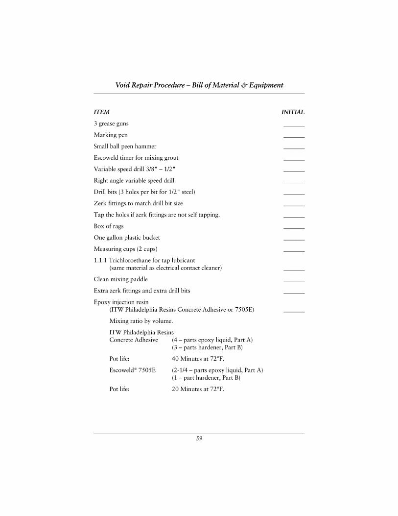
59
ITEM INITIAL
3 grease guns _______
Marking pen _______
Small ball peen hammer _______
Escoweld timer for mixing grout _______
Variable speed drill 3/8" – 1/2" _______
Right angle variable speed drill _______
Drill bits (3 holes per bit for 1/2" steel) _______
Zerk fittings to match drill bit size _______
Tap the holes if zerk fittings are not self tapping. _______
Box of rags _______
One gallon plastic bucket _______
Measuring cups (2 cups) _______
1.1.1 Trichloroethane for tap lubricant (same material as electrical contact cleaner) _______
Clean mixing paddle _______
Extra zerk fittings and extra drill bits _______
Epoxy injection resin (ITW Philadelphia Resins Concrete Adhesive or 7505E) _______
Mixing ratio by volume.
ITW Philadelphia Resins Concrete Adhesive (4 – parts epoxy liquid, Part A)
(3 – parts hardener, Part B)
Pot life: 40 Minutes at 72°F.
Escoweld® 7505E (2-1/4 – parts epoxy liquid, Part A)(1 – part hardener, Part B)
Pot life: 20 Minutes at 72°F.
Void Repair Procedure – Bill of Material & Equipment
60
MIXING MATERIALS:Mix only what can be used within the pot life of the injection resin you are using.
MIXING INSTRUCTIONS:Measure the proper amounts of resin and hardener into the plastic bucket. Mixthe liquids three (3) minutes, refer to Escoweld timer. Immediately after mixing,pour the mixed resin into the grease gun and start injection.
Void Repair Procedure – Bill of Material & Equipment

ESCOWELD ESCOWELD ESCOWELD ESCOWELD EPOXY GROUT SYSTEMS EPOXY GROUT SYSTEMS EPOXY GROUT SYSTEMS EPOXY GROUT SYSTEMS Drawings
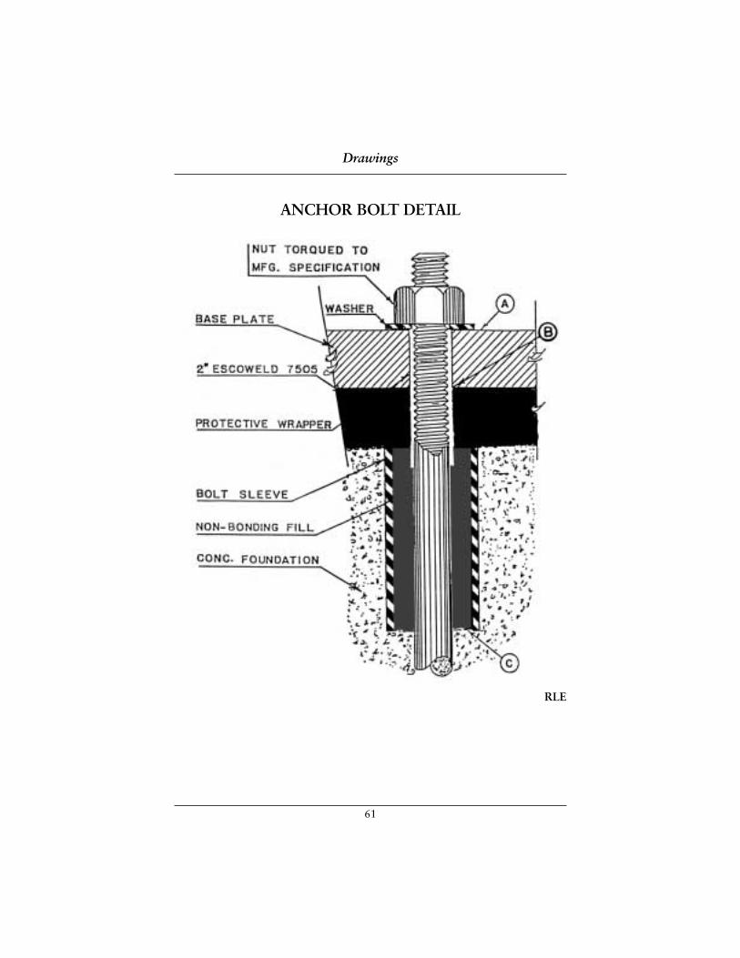
61
Drawings
ANCHOR BOLT DETAIL
RLE
62
ANCHOR BOLT DETAILOccasionally equipment manufacturer’s recommendations will vary from thoselisted below. Therefore, we recommend that they also be consulted.
Sheet 1 illustrates the recommended method of protecting an anchor bolt duringthe pouring of ESCOWELD® 7505E epoxy grout. The normal sequence ofpreparation and the mixing and pouring of ESCOWELD® 7505E is as follows:
1. Remove all laitence and foreign matter from the surface of the concrete by the use of a chipping hammer. All area coming in contact withESCOWELD® 7505E should be roughened.
2. Remove all debris such as concrete chips and all moisture from the boltsleeve by the use of an air hose.
3. Protect the anchor bolt with duct tape or a plastic sleeve as far down intothe sleeve as possible and up to the point that the top of the base plate willbe even with the protective material to prevent ESCOWELD® 7505E fromcoming in contact with the anchor bolt.
4. Fill the bolt sleeve with a non-bonding material.
5. Sand blast the bottom of the base plate to obtain a 1 to 1-1/2 mil profile and coat with ITW Philadelphia Resins Rust Inhibitive Primer to a thicknessof 3 to 5 mils DFT.
6. Mix and pour ESCOWELD® 7505E in accordance with “InstallationSpecification for Pumps and Drivers when Using Epoxy Grouts”.
By following the recommended steps listed above, the anchor bolt is less suscep-tible to overstress during tightening and to loosening effects during service, caused by vibration or bolt creep. This is because the use of the protectivewrapper maximizes the length A-C over which the bolt is allowed to stretch when it is tensioned. The increase or decrease in tensile load associated with a small movement is thus minimized.
1620D, 8/88
Drawings
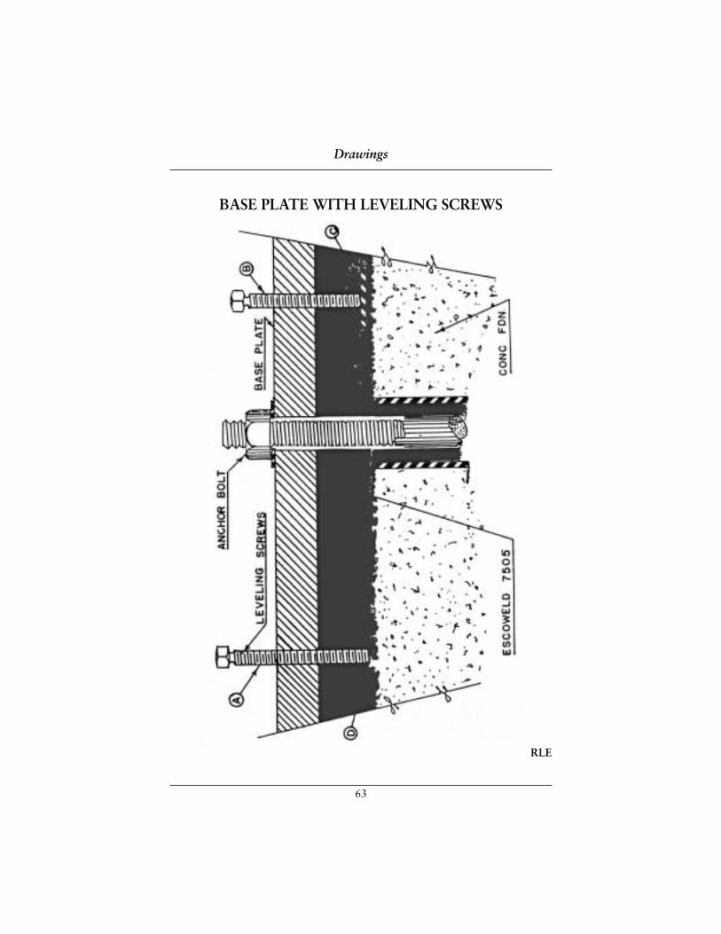
63
Drawings
BASE PLATE WITH LEVELING SCREWS
RLE
64
BASE PLATE WITH LEVELING SCREWSThe leveling screw (Point B) and its base plate (Point C) illustrate one of theproper methods of leveling a base plate. This procedure is as follows:
1. Remove all laitance and foreign matter from the surface of the concrete by the use of a chipping hammer. All areas coming in contact withESCOWELD should be roughened.
2. Remove all debris such as concrete chips and all moisture from the boltsleeve by the use of an air hose.
3. Embed the leveling screw pad to support the load imposed by the levelingscrew with ESCOWELD® 7505.
4. Protect the anchor bolt with duct tape or a plastic sleeve as far down intothe sleeve as possible and up to the point that the top of the base plate willbe even with the protective material to prevent ESCOWELD® from coming in contact with the anchor bolt.
5. Fill the bolt sleeve with non-bonding material.
6. Sand blast the bottom of the base plate to obtain a 1 to 1-1/2 mil profile and coat with ITW Philadelphia Resins Rust Inhibitive Primer (use a paintbrush roller) to a thickness of 3 to 5 mils DFT.
7. Set and level base plates.
8. Mix and pour ESCOWELD® in accordance with “Installation Specificationfor Pumps and Drivers when Using Epoxy Grouts”.
9. After ESCOWELD® has hardened, remove the jack screws and fill the holewith ESCOWELD®.
Drawings
65
BASE PLATE WITH LEVELING SCREWS (continued)
11. After ESCOWELD® has cured and the leveling screws have been removed,torque the anchor bolt to its proper tension.
When the anchor bolt is torqued, the forces that develop are distributed evenlyunder the base plate area if the leveling screws or solid shims are removed. If theleveling screws were not backed off or the shims removed from the grout, thenthe load would be concentrated at these points. Note the jack leveling screw atPoint A and its insufficient supporting surface at Point D in comparison with thejack leveling screw at Point B and the base plate C which is properly grouted.
1622D
Drawings
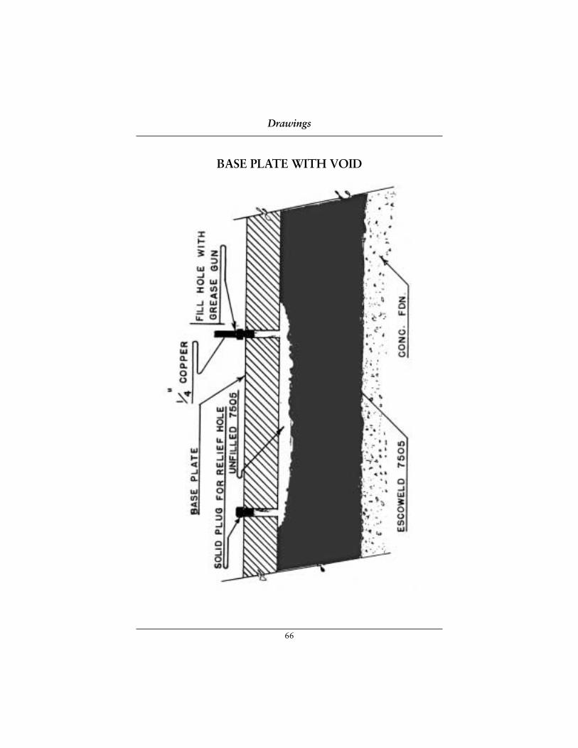
66
Drawings
BASE PLATE WITH VOID
67
BASE PLATE WITH VOIDTo repair in place a void under a base plate that is grouted, the recommendedprocedure is as follows:
1. Locate the void by tapping on the top of the base plate with an instrumentsuch as a hammer to determine the exact area of the void. Mark this areawith a piece of chalk.
2. Drill two or more holes through the base plate into the void and tap same.
3. Measure the depth of the void beneath the base plate. If the depth is lessthan 1/2 inch, it can be pressure injected in one pour.
4. Use copper tubing and fittings and a hand grease gun to injectESCOWELD® 7505E into the void.
5. Continue injecting ESCOWELD® 7505E through the fill hole until the reliefholes are allowing ESCOWELD® 7505E to escape with no air bubblesevident. When this occurs, insert the solid plugs into the relief holes andcontinue with pressure injection. Be most careful that you do not exertexcessive pressure causing the base plate to warp.
6. After reasonable resistance is met, the copper tube should be bent over and crimped to prevent backflow.
7. If the base plate is of such a nature that a few thousandth inch warp wouldbe detrimental, a dial indicator can be used in order that any warping of thebase plate can be observed immediately and the pressure can be released sothe base plate can return to its original level.
By following the recommended steps listed above, large voids under base platescan be filled and excessive vibration can be reduced.
Code 1623D, 8/88
Drawings
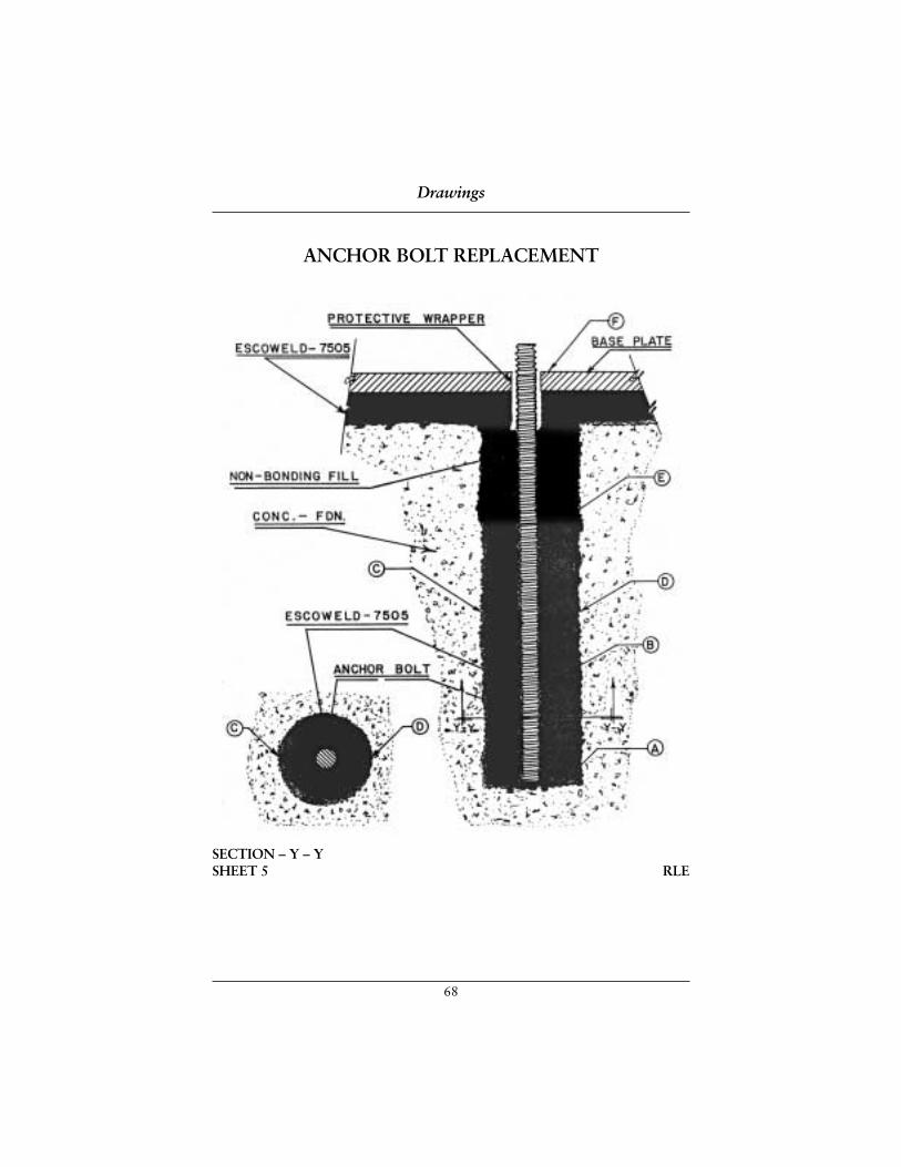
68
Drawings
ANCHOR BOLT REPLACEMENT
SECTION – Y – YSHEET 5 RLE
69
ANCHOR BOLT REPLACEMENTFrequently anchor bolt relocations are required in new and existing foundations.The recommended procedure for the installation is as follows:
1. Drill a hole of a diameter as specified by the engineer from the top of theconcrete foundation to Point A.
2. Remove all latent and foreign matter from the surface of the concrete by the use of a chipping hammer. All areas coming in contact withESCOWELD® should be roughened.
3. Remove all debris such as concrete chips and all moisture from the boltsleeve by the use of an air hose.
4. Insert a threaded anchor bolt of a size and length as specified and grout withESCOWELD® 7505 in the areas shown in Blue from Point A to Point E andfrom Point C to Point D.
5. Protect the anchor bolt with duct tape or a plastic sleeve as far down intothe sleeve as possible and up to the point that the top of the base plate willbe even with the protective material to prevent ESCOWELD® from coming in contact with the anchor bolt.
6. Fill the bolt sleeve with non-bonding material.
7. Sand blast the bottom of the base plate to obtain a 1 to 1-1/2 mil profile and coat with ITW Philadelphia Resins Rust Inhibitive Primer to a thickness of 3 to 5 mils DFT.
8. Set and level base plate.
9. Mix and pour ESCOWELD® in accordance with “Installation Specificationfor Pumps and Drivers when Using Epoxy Grouts”.
Drawings
70
ANCHOR BOLT REPLACEMENT (continued)
By following the recommended steps listed above. the anchor bolt is protected Insuch a manner that the tension in the bolt can be developed to its designedstrength over the area from Point A to Point C without fear of restrictions bybonding to the ESCOWELD® from Point E to Point F. The depth E-A of the holeshould be calculated using the shear strength of the concrete, the shear strengthof the grout, and the tensile strength needed to be developed. The shear strengthat the interface at Point C and D between the epoxy grout and the concrete isincreased considerably when a rotary type jack drill is used to cut the hole ratherthan using a core saw which has a much smoother type cut.
Order 1627, 8/88
Drawings

ESCOWELD ESCOWELD ESCOWELD ESCOWELD EPOXY GROUT SYSTEMS EPOXY GROUT SYSTEMS EPOXY GROUT SYSTEMS EPOXY GROUT SYSTEMS Grouting Seminars
71
Dear ESCOWELD Customer:
We would like to present our ESCOWELD® baseplate-grouting seminar to yourengineering staff. This unique slide seminar covers a step-by-step procedure forgrouting baseplates for pumps and other equipment in a single operation. Wewould suggest the attendance be made up of your civil and mechanical engineers as well as the maintenance foremen who actually supervise equipment installations.
This presentation is not a commercial product seminar. It endeavors to teachproper design of baseplates and foundations as well as proper installationpractices. There is usually only one opportunity to do a grouting job right and if these guidelines are followed, it will be successful.
Proper installation and grouting of machinery baseplates reduces maintenancecost. Experience has proven that pumps with poorly installed baseplates havemore vibration, which leads to alignment problems and premature failure ofbearings, mechanical seals and couplings.
In 1985 a major chemical plant in Texas started monitoring over 2,000 pumpbases. Improved grouting procedures, as covered in this seminar, improved their“mean running time” from 8.5 months in 1985 to 13.2 months in 1988 and toover 22 months in 1990. Nothing changed but the foundation and baseplatepreparation, alignment, and grouting procedures.
Our Regional Managers or our local representatives could be available to presentthis one-hour seminar to your engineering group at your location. Enclosed is anoutline of the format which you may wish to circulate to determine interest. Thereis no charge or obligation. If there is sufficient interest, please contact our office.
Tel: 215-855-8450Fax: 215-855-4688
www.escoweld.com
Grouting Seminars
72
ESCOWELD® EPOXY GROUT SYSTEMS MACHINERY BASEPLATE INSTALLATION AND EPOXY GROUTINGA common sense course illustrating field-proven techniques for machinerybaseplate preparation, installation, leveling and epoxy grouting. A void-freebaseplate grout job is obtainable using the grout procedure detailed in this course.
Why Improve Machinery Baseplate Installations?
❐ To reduce bearing and mechanical seal failures
❐ To improve mechanical alignment
❐ To reduce vibration
Why Use Epoxy Grout?
❐ One-time installation cost vs. repeated machinery failure costs
❐ Epoxy grout bonds to baseplate and concrete
❐ Epoxy grout seals the concrete foundation
❐ Compatibility of epoxy grout and concrete
❐ Comparative vibration damping of concrete and epoxy grout
❐ Excellent chemical resistance to acids and caustics
Baseplate Leveling Procedure
❐ Review of methods for supporting baseplate prior to grouting
❐ Use of jackscrews for leveling baseplate
❐ Foundation preparation prior to baseplate placement
❐ Use of machinist’s level or optical level for leveling baseplate
❐ Introduction of the “One-Pour” grouting method
Baseplate Preparation
❐ Ensure that baseplate meets specifications of engineering and purchasing
❐ Adequate number and location of air-vent holes
❐ Baseplate preparations as performed by field personnel
Grouting Seminars
73
New Concrete Preparation
❐ Sufficient cure time for concrete
❐ Testing of concrete samples
❐ Chipping of surface to remove laitance and chamfer edges
❐ Coating of chipped surface
Old Concrete Preparation
❐ Checking for surface moisture
❐ Checking/sealing of cracks
❐ Chipping of surface to remove laitance
❐ Compressive strength testing of existing foundation
❐ Covering (protection)
Anchor Bolts
❐ Replacing broken anchor bolts
❐ Adequate free length of anchor bolt for proper stretch upon final torque
❐ Use of sleeves to provide free length
❐ Filling of sleeves with non-bonding material
❐ Methods used to protect anchor bolt free length from epoxy bonding
Grout Forms
❐ Design of grout forms
❐ Location of Vent holes
❐ Waxing of grout forms
❐ Construction of proper grout forms
❐ Methods to assure liquid-tight forms
Grouting Seminars
74
Epoxy Grout Placement
❐ Use of checklist prior to grout placement
❐ Proper protection of machined surfaces
❐ Storage of grouting material prior to use
❐ Proper organization of materials for safety and ease of mixing
❐ Method of mixing epoxy/hardener
❐ Method of mixing epoxy grout
❐ Method of epoxy grout placement under baseplate
Repair Method for Voids in Existing Baseplates
❐ Procedure to locate voids
❐ Procedure to repair voids
The techniques for baseplate installation and epoxy grouting, covered in thiscourse, are applicable for any pump, turbomachinery baseplate, bed rail or skidinstallation and most machinery used in refineries, chemical/petrochemicalplants, pulp and paper mills, water treatment and power generation facilities.
This presentation is free of charge and lasts approximately one hour. Please contact your local ESCOWELD representative for further details.
Grouting Seminars

ESCOWELD ESCOWELD ESCOWELD ESCOWELD EPOXY GROUT SYSTEMS EPOXY GROUT SYSTEMS EPOXY GROUT SYSTEMS EPOXY GROUT SYSTEMS Cement Grouts
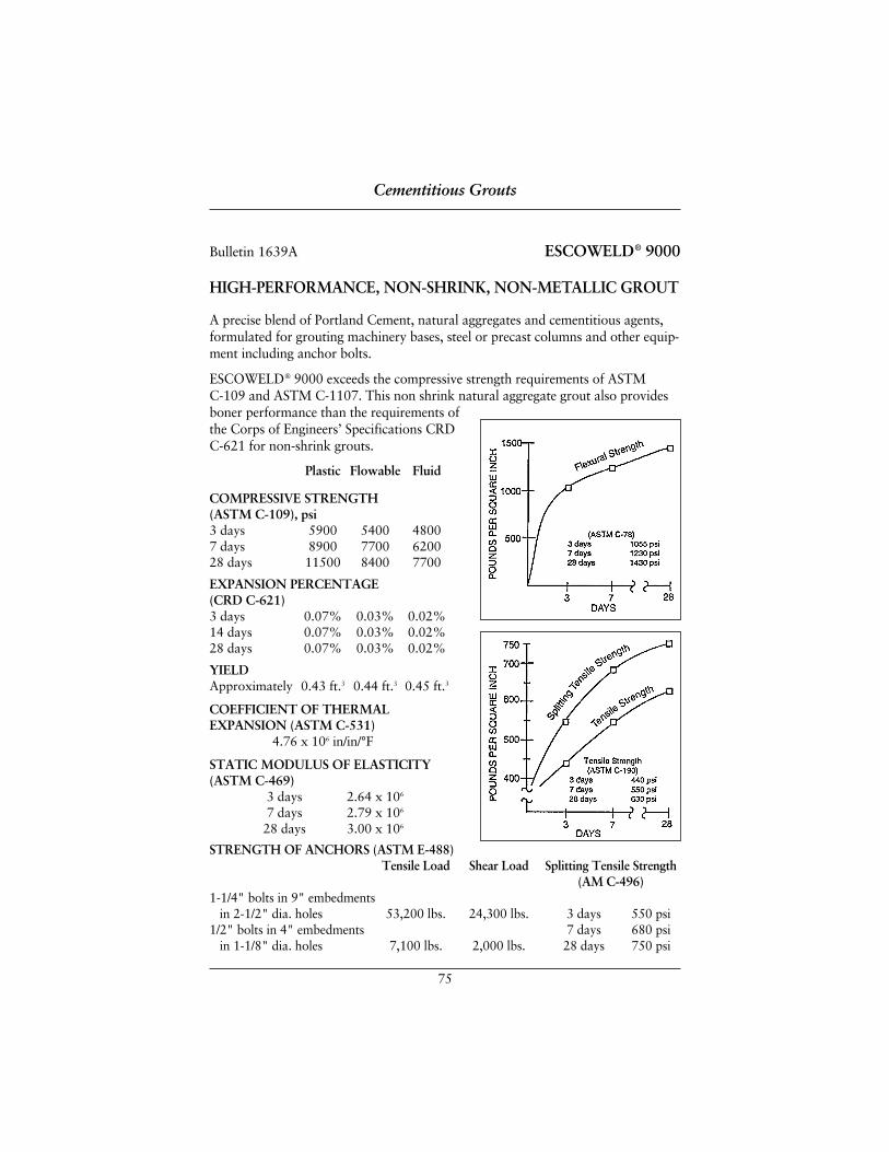
75
A precise blend of Portland Cement, natural aggregates and cementitious agents,formulated for grouting machinery bases, steel or precast columns and other equip-ment including anchor bolts.
ESCOWELD® 9000 exceeds the compressive strength requirements of ASTM C-109 and ASTM C-1107. This non shrink natural aggregate grout also providesboner performance than the requirements ofthe Corps of Engineers’ Specifications CRDC-621 for non-shrink grouts.
Plastic Flowable Fluid
COMPRESSIVE STRENGTH (ASTM C-109), psi3 days 5900 5400 48007 days 8900 7700 620028 days 11500 8400 7700
EXPANSION PERCENTAGE (CRD C-621)3 days 0.07% 0.03% 0.02%14 days 0.07% 0.03% 0.02%28 days 0.07% 0.03% 0.02%
YIELDApproximately 0.43 ft.3 0.44 ft.3 0.45 ft.3
COEFFICIENT OF THERMALEXPANSION (ASTM C-531)
4.76 x 10⁶ in/in/°F
STATIC MODULUS OF ELASTICITY(ASTM C-469)
3 days 2.64 x 10⁶
7 days 2.79 x 10⁶
28 days 3.00 x 10⁶
STRENGTH OF ANCHORS (ASTM E-488)Tensile Load Shear Load Splitting Tensile Strength
(AM C-496)1-1/4" bolts in 9" embedments
in 2-1/2" dia. holes 53,200 lbs. 24,300 lbs. 3 days 550 psi1/2" bolts in 4" embedments 7 days 680 psi
in 1-1/8" dia. holes 7,100 lbs. 2,000 lbs. 28 days 750 psi
Bulletin 1639A ESCOWELD® 9000
HIGH-PERFORMANCE, NON-SHRINK, NON-METALLIC GROUT
Cementitious Grouts
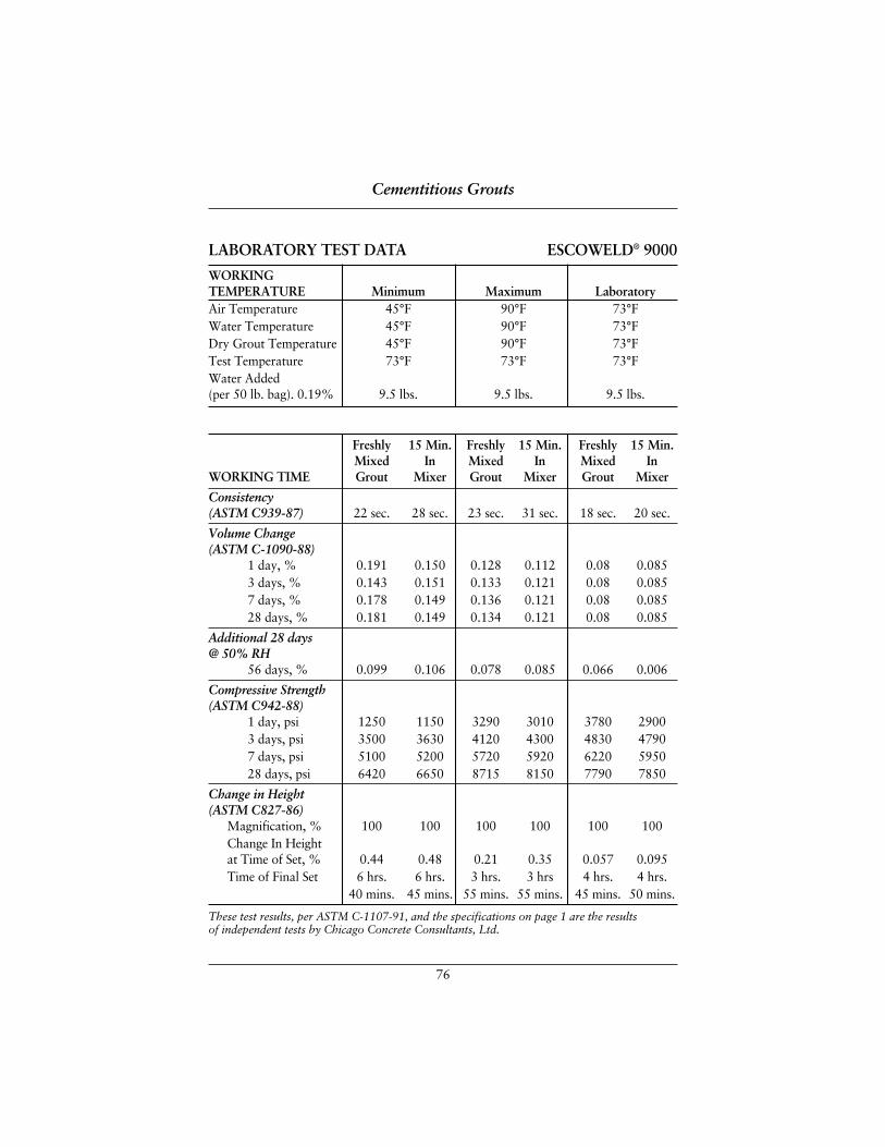
76
LABORATORY TEST DATA ESCOWELD® 9000
WORKING TEMPERATURE Minimum Maximum LaboratoryAir Temperature 45°F 90°F 73°FWater Temperature 45°F 90°F 73°FDry Grout Temperature 45°F 90°F 73°FTest Temperature 73°F 73°F 73°FWater Added (per 50 lb. bag). 0.19% 9.5 lbs. 9.5 lbs. 9.5 lbs.
Freshly 15 Min. Freshly 15 Min. Freshly 15 Min.Mixed In Mixed In Mixed In
WORKING TIME Grout Mixer Grout Mixer Grout Mixer
Consistency(ASTM C939-87) 22 sec. 28 sec. 23 sec. 31 sec. 18 sec. 20 sec.
Volume Change(ASTM C-1090-88)
1 day, % 0.191 0.150 0.128 0.112 0.08 0.0853 days, % 0.143 0.151 0.133 0.121 0.08 0.0857 days, % 0.178 0.149 0.136 0.121 0.08 0.08528 days, % 0.181 0.149 0.134 0.121 0.08 0.085
Additional 28 days @ 50% RH
56 days, % 0.099 0.106 0.078 0.085 0.066 0.006
Compressive Strength (ASTM C942-88)
1 day, psi 1250 1150 3290 3010 3780 29003 days, psi 3500 3630 4120 4300 4830 47907 days, psi 5100 5200 5720 5920 6220 595028 days, psi 6420 6650 8715 8150 7790 7850
Change in Height (ASTM C827-86)
Magnification, % 100 100 100 100 100 100Change In Heightat Time of Set, % 0.44 0.48 0.21 0.35 0.057 0.095Time of Final Set 6 hrs. 6 hrs. 3 hrs. 3 hrs 4 hrs. 4 hrs.
40 mins. 45 mins. 55 mins. 55 mins. 45 mins. 50 mins.
Cementitious Grouts
These test results, per ASTM C-1107-91, and the specifications on page 1 are the results of independent tests by Chicago Concrete Consultants, Ltd.
77
HIGH-PERFORMANCE, NON-SHRINK, NON-METALLIC GROUT• Hardens free of bleeding. settlement or shrinkage
• Surpasses requirements of ASTM C-1107 and CRD C-621
• High-quality aggregates help to provide excellent strength and workability
ApplicationSurface Preparation: Remove all dirt, oil, loose or foreign material. Any metal incontact with grout must be free of rust, oil, grease, etc. Surface must be sound androughened to insure proper bonding. Prior to placing grout, surface should besaturated for a minimum period of four hours. Remove all excess water beforeplacement of grout. Bolts, baseplates, and equipment must be secure and rigidbefore placement of grout.
Forms: Must allow for a continuous placement of grout. Provisions for venting to avoid air entrapment must be made. From the placing side, provide a 45° anglein the forms to a height suitable to provide a head of grout during placement. On all sides provide a minimum 1/2" horizontal clearance between the baseplate and forms. Forms should be at least 1" higher than the bottom of the baseplate.
Mixing: Use a mechanical mixer for small jobs, use a 1/2’ drill with paddle; for large jobs, use a mortar mixer.
Start with minimum water requirements. Add water to mixer first, then slowlyadd powder. Add additional water as required for desired consistency.
Water requirements per bag are:
Curing: Immediately cover with clean wet rags or polyethylene sheeting (DONOT use burlap) and keep moist until final set. After final set, remove rags andapply an ASTM C-309 curing compound.
Deep Applications: Pre-washed graded 3/8" pea gravel may be used inapplications thicker than 2":
2" to 5": Add 25% 3/8" pea gravel by weight.
5" and over: Add 50% 3/8" pea gravel by weight.
Cementitious Grouts
Plastic50 lbs. grout6.80 to 7.00 pints water0.85 to 0.88 gal.7.05 to 7.30 lbs.3.18 to 3.29 liters
Flowable50 lbs. grout7 to 8 pints water0.88 to 0.94 gal.7.30 to 7.80 lbs.3.29 to 3.79 liters
Fluid50 lbs. grout8.00 to 9.25 pints water1.00 to 1.19 gal.8.33 to 9.50 lbs.3.79 to 4.40 liters
78
Yield: Yield per 50 lbs: Mixed with 1 gallon or 8.33 lbs. will yield approximately.45 ft3. Less water will reduce yield slightly.
Hot Weather Grouting (75° to 100°F): Provide shade for area to be grouted. Usecool mixing water. Protect grout from the sun for up to 48 hours.
Cold Weather Grouting: Raise the temperature of the area to be grouted with spaceheaters or steam (min. 40°F). Preheat mixing water. Cover grout to retain warmth.
Placing: Place continuously and quickly. Start from one side to avoid airentrapment. Be sure grout fills all spaces and remains in contact with plate. DO NOT VIBRATE. For damp packing, rod from one side to opposite side.
Packaging
50 lb. triple lined bag • Sixty 50 lb. bags per pallet
Receiving
All bagged products should be checked for dryness prior to signing shipping papers.
Storage
Store in a cool, dry interior area. At no time should material be exposed to highmoisture, rain or snow conditions.
Limitations/Precautions
DO NOT place at temperatures below 40°F or if the temperature is expected tofall below 40°F in the next twenty-four hour period.
DO NOT over water. This can cause bleeding or separation. DO NOTretemper. DO NOT add cement, sand, aggregate or admixtures. DO NOT mixmore than can be used in fifteen minutes.
Caution: Contains Portland Cement and sand.
Avoid hazards by following all precautions found in the Material Safety DataSheet (MSDS), product labels and technical literature. Please read thisinformation prior to using the product.
Cementitious Grouts
79
Warranty The manufacturer warrants that at the time and place we make shipment, ourmaterials will be of good quality and will conform with our publishedspecifications in force on the date of acceptance of the order. THEFOREGOING WARRANTY SHALL BE EXCLUSIVE AND IN LIEU OF ANY OTHER WARRANTY, EXPRESS OR IMPLIED, WARRANTIES OFMERCHANTABILITY AND FITNESS FOR A PARTICULAR PURPOSE,AND ALL OTHER WARRANTIES OTHERWISE ARISING BY OPERATIONOF LAW, COURSE OF DEALING, CUSTOM OR TRADE OR OTHERWISE.As the exclusive remedy for breach of this Warranty, we will replace defectivematerials, provided, however, that the buyer examines the materials whenreceived and promptly notifies us in writing of any defect before the materialsare used or incorporated into a structure. Twelve (12) months after themanufacturer has shipped the materials, all our Warranty and other duties withrespect to the quality of the materials delivered shall conclusively be presumed to have been satisfied, all liability therefore terminates, and no action for breachof any duties may thereafter commence. The manufacturer shall in no event beliable for consequential damages. Unless otherwise agreed to in writing, nowarranty is made with respect to materials not manufactured by manufacturer.We cannot warrant or in any way guarantee any particular method of use ofapplication or the performance of materials under any particular condition.Neither this Warranty nor our liability may be extended or amended by oursalespeople, distributors or representatives or by any sales information ordrawings.
ESCOWELD®
ITW Philadelphia Resins130 Commerce Drive • Montgomeryville, PA 18936
For informative material and a list of local stockingdistributors who provide on-site technical support, contact:
ESCOWELD® National Sales Manager, 225-922-7731, Fax 225-922-7732ESCOWELD® International Operations, 215-855-8450, Fax 215-855-4688
Cementitious Grouts

ESCOWELD ESCOWELD ESCOWELD ESCOWELD EPOXY GROUT SYSTEMS EPOXY GROUT SYSTEMS EPOXY GROUT SYSTEMS EPOXY GROUT SYSTEMS Attachments
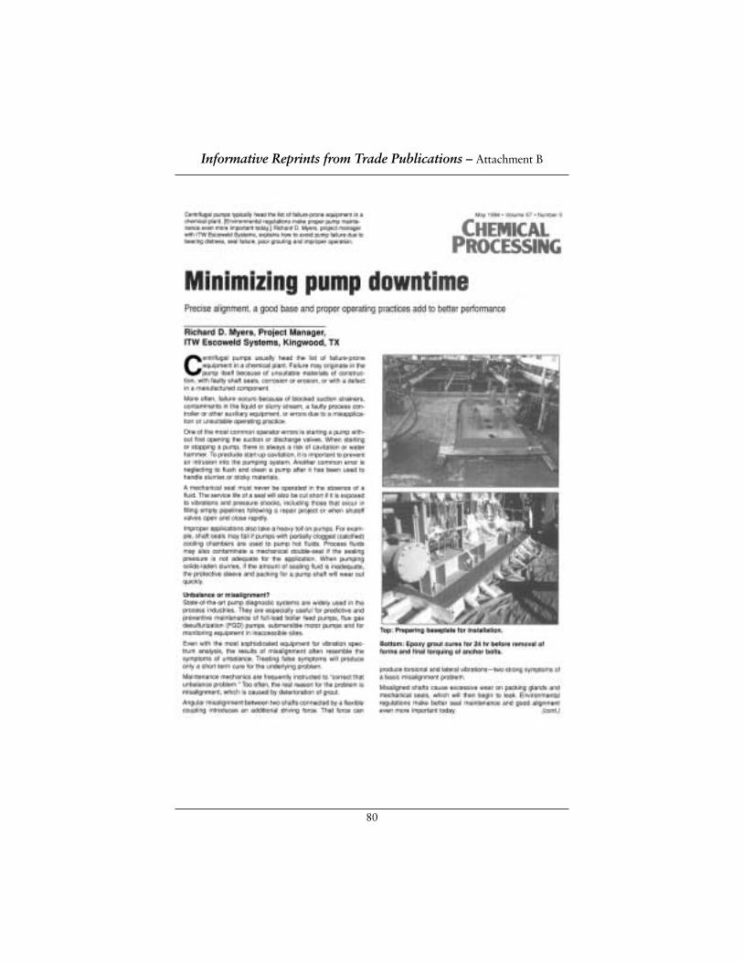
80
Informative Reprints from Trade Publications – Attachment B
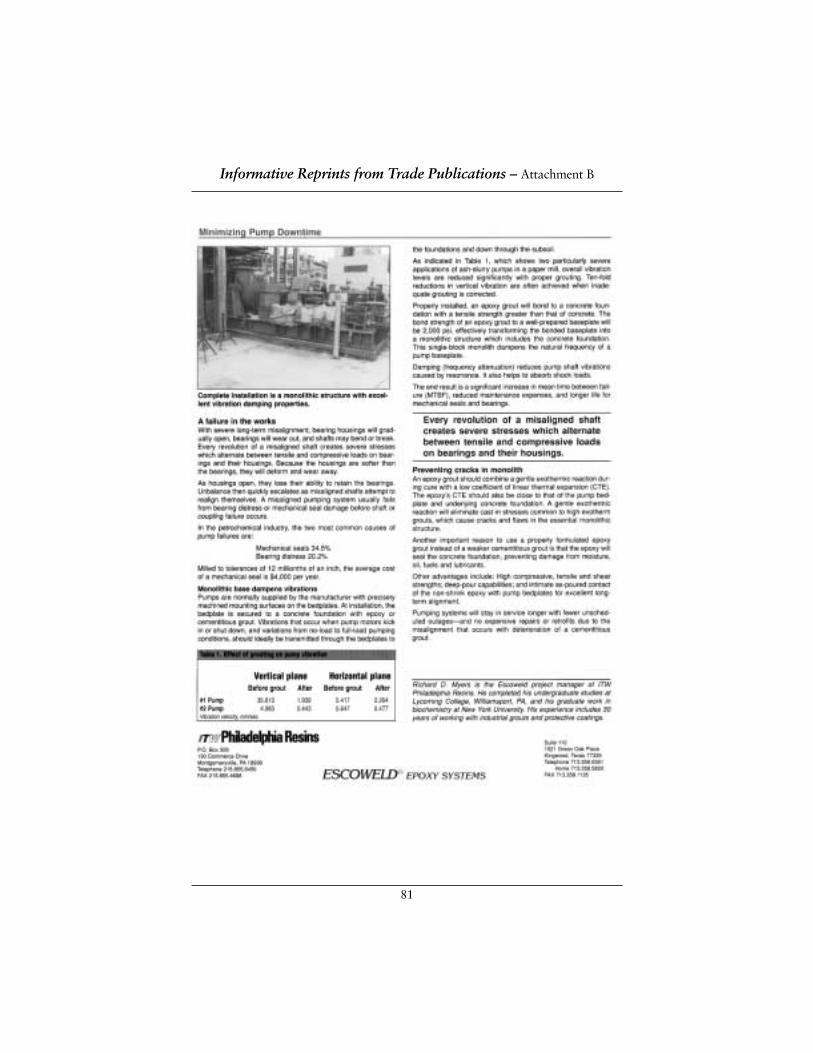
81
Informative Reprints from Trade Publications – Attachment B
82
Informative Reprints from Trade Publications – Attachment B

83
Informative Reprints from Trade Publications – Attachment B
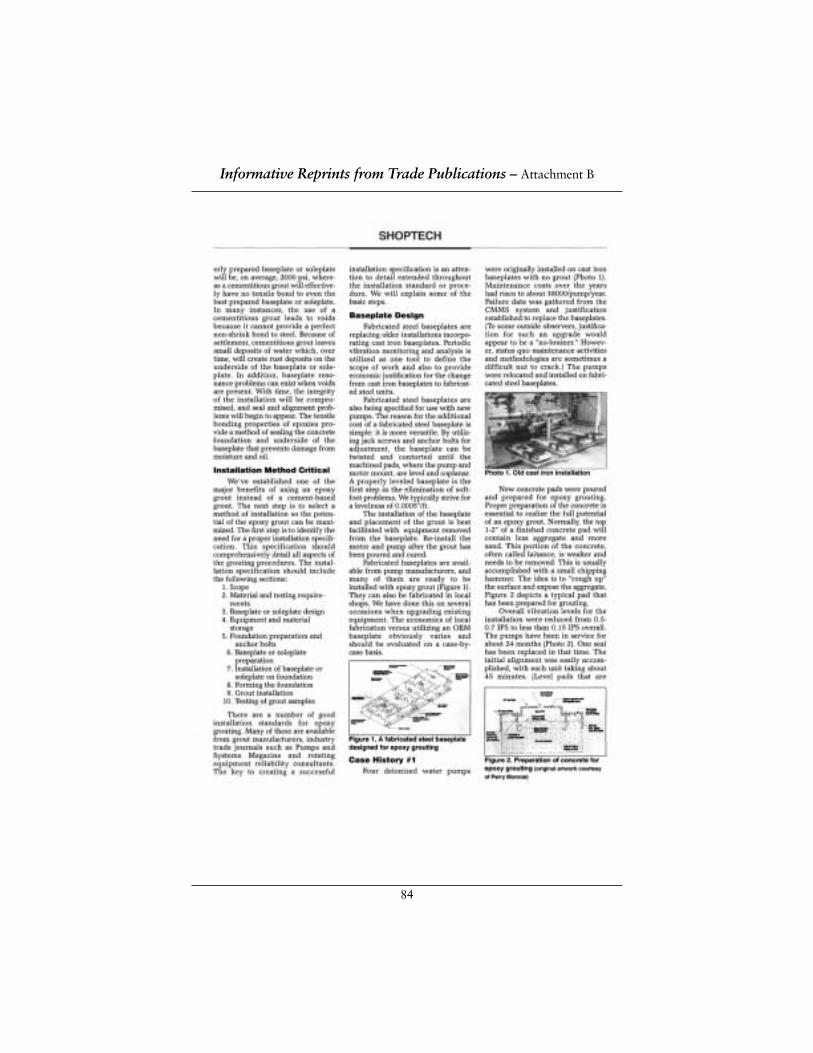
84
Informative Reprints from Trade Publications – Attachment B
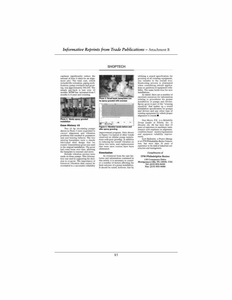
85
Informative Reprints from Trade Publications – Attachment B
86
Keep your pumps on-line by filling voids under baseplates that amplify destructive wiggles,wobbles and shakes
BUILD A BETTER FOUNDATION TO REDUCE COSTLY DOWNTIME
by Richard D. MyersProject Manager
ITW Escoweld® Systems
Centrifugal pumps usually lead the list of failure-prone equipment in refineriesand major chemical/petrochemical plants, where downtime expenses average$250,000 per hour. Pumps are also a major contributor to emergency shut-downs and production delays in pulp and paper mills, where downtime expensesaverage $100,000 per hour.
Pumps are commonly supplied with precisely machined mounting surfaces on their bedplates. At installation, a pump bedplate is adapted to a concretefoundation with an epoxy or cementitious grout. Vibrations that occur when a pump motor kicks in or shuts down, or when pumping conditions vary fromshut-off to full flow, should ideally be transmitted through the bedplate to thefoundation and down through the subsoil.
Properly installed, a structural epoxy grout will bond to a concrete foundationand to a pump bedplate with tensile and shear strengths that are much higherthan concrete, effectively transforming a bonded baseplate into a monolithicstructure which includes the concrete foundation. The single-block monolithdampens vibrations produced by the pump.
Effective damping (frequency attenuation) reduces pump-shaft vibrations causedby resonance. It also helps to absorb shock loads. The end result is a significantincrease in the mean time between failures (MTBF), reduced maintenanceexpenses, and longer life for mechanical seals and bearings.
“Soft foot” amplifies destructive vibrationsGrouting a pump baseplate to a foundation requires careful attention to detail.Voids between a baseplate and its foundation will cause a soft-foot conditionthat will amplify vibrations developed at resonant frequencies.
When a cementitious grout is used, voids frequently occur because that groutcannot provide a perfect non-shrink bond to a steel baseplate. Cement mix waterwill then bleed into the voids to accelerate rust and metal deterioration, thusincreasing the amplification of the wiggles, wobbles and shakes that causedamage and downtime.
Informative Reprints from Trade Publications – Attachment B
87
Voids can also occur if a structural epoxy grout was installed without sufficientvent holes in the baseplate, allowing air to be trapped and thus causing “bubbles”in the grout.
Other conditions that cause voids include: improper baseplate preparation (e.g., dirty, greasy, not sandblasted); use of an improper primer that will notbond to the metal baseplate and/or to an epoxy grout; insufficient static headpressure when a liquid epoxy grout is poured; and any baseplate movementduring grouting or during the 24-hr. epoxy cure time.
Since cementitious grouts require a 20-day cure, the cost of downtime can runinto hundreds of thousands of dollars in small plants and into many millions of dollars in major facilities if epoxy grouts aren’t used to install new pumps or to retrofit or repair existing installations.
Fill voids to keep your pumps on-lineWhile the best prevention is careful, professional epoxy grouting, voids in a foun-dation system may be filled, after-the-fact by pressure injecting a liquid epoxy groutinto each void. By filling all voids, you can provide intimate contact between apump baseplate and its foundation and turn a poor grouting job into a successfulretrofit that should prevent problems until the next scheduled shutdown.
The first step in filling voids is to locate them. It’s a simple process. All you needis a small ball-peen hammer and a marking pen. A ball-peen hammer willproduce a better ring than a large hammer, large bolt or other striking tool.
Tap the hammer on the baseplate and listen. If you strike above a void, you willhear a ringing sound instead of a dull thud. By tapping out from any spot whereyou hear a ring, you can easily determine the extent of the void. Mark that area.(This sounding procedure should not be conducted until an epoxy grout hascured for at least 24 hours.)
The next step is to drill injection and vent holes through the baseplate. A smallvoid may require only one injection hole and a single vent hole. Large voids willrequire several vent holes around the perimeter of each void and an injectionhole in the center. Injection holes should not be more than 12" to 14" apart.You may need to sketch several layouts to pinpoint one that will work best.
Informative Reprints from Trade Publications – Attachment B
88
When in doubt don’t drill or fillIf you are not certain there is a void, do not drill that area. An indefinite ringingsound, something between a dull thud and a dear ring, may result from cross-bracing under the bedplate or from vertical gusset reinforcements near motor ordriven mounts. Drilling and pumping epoxy into such areas may, very likely,disband the baseplate and cause additional voids.
If access is available from above the baseplate, injection and vent holes should bedrilled vertically. Otherwise, the holes can be drilled at any angle, even horizontallyif the configuration of the pump baseplate and drive machinery permits.
After drilling the holes, determine the depth of each void by inserting a stiff wireinto the hole and measuring the depth of penetration. If the voids are less than 1/4"deep, you can use a two-part (resin and hardener) epoxy grout. To inject the mixedliquid epoxy, you will need to drill and tap every injection hole for either a 1/8" or1/4" pipe fitting. (Zerk fittings should be substituted if grease guns are used to pourliquid epoxy into the voids.) Tap each vent hole, too, because it may be used as aninjection hole in the final stages of epoxy placement.
Deeper voids require a three-part epoxy (resin, hardener and filler/aggregate).Voids deeper than 1" also require an epoxy grout formulated for highflow; andthey necessitate larger injection holes.
Inject epoxy to fill voidsThe liquid epoxy is injected from a gun into the fittings, screwed into the injectionholes. If the job requires fewer than 25 injection holes and less than two gallons ofepoxy, you can use a hand-held grease gun. The advantage of a grease gun is it’scheap. If the injection process is delayed and the epoxy hardens in the gun, simplythrow it away.
For larger jobs, use a pressure pot and hoses. If compressed air is available, up to two hoses can be used on a pressure pot. If you use a pressure pot, be sure thepressure under the baseplate does not exceed 25 to 30 psi. Greater pressures maydeform or delaminate a securely bonded monolith.
For even larger repair jobs, you may need an air-operated drum pump, similar to a service station grease rack. If you use such a pump, install a pressure regulatoron the air side to prevent over-pressurizing the grout and distorting the baseplate.The pump should have no greater than a 20:1 ratio, and it must fit into a five-gallon bucket.
If you use anything other than a throw-away grease gun, you will need to clean theequipment frequently to keep the epoxy from setting up inside the equipment andruining it. Therefore, be sure your equipment is compatible with clean-up solvents.
Informative Reprints from Trade Publications – Attachment B
89
A labor-intensive operationBe sure you have enough people and equipment to do the job in one continuousprocess instead of stretching it out over a long time. Because the epoxy groutshould be injected into large voids through several holes simultaneously, multipleguns will be needed.
Use an accurate dial indicator to measure any movement at pump couplings.There will be very little movement. A dial indicator should also be mountedwithin 6" of the point of injection to make certain pressure is not developingunder the baseplate.
If the dial indicator moves a maximum of 3 mils, stop injection of the liquidepoxy and allow the pressure to dissipate. Remember, this procedure is notintended to develop pressure under the baseplate. The only reason to use agrease gun or other "pumping system" is to place the liquid grout in each void.
Measure the resin and hardener accurately. Improper proportions will preventproper curing. Mix the material in small batches (e.g., only as much as you willneed for 30 minutes; and never more than one gallon). Structural epoxies set upquickly, so don’t mix too large a batch. Remember, too, that hand-held greaseguns don’t hold much epoxy.
Before using a grease gun, remove and discard the end cap and spring plunger.During the application process, you will hold the grease gun vertically while a helper pours epoxy in through the open top. Your helper must be sure tomaintain a continuous liquid flow into the gun so that no air is entrapped with the epoxy and injected below the baseplate.
During the injection process there should be no external pressure on thebaseplate. Do not stand or lean on the baseplate.
Little pressure, lots of patience This is a time for minimum pressure and maximum patience. Begin injecting theepoxy at one of the central injection holes and continue until material comes outof the open vent hole. If the pump base slopes, as with an API pump base thattilts down from the driven end, begin at the low end and work upward.
If you are pumping the liquid epoxy and you feel pressure, as you will if you’refilling a void only a few thousandths of an inch deep, stop pumping periodicallyto let the pressure within the void subside.
Informative Reprints from Trade Publications – Attachment B
90
Never force epoxy into a void. Remember, high pressure can distort a baseplate.Instead of forcing the epoxy in, use a start/stop action until the void is full andepoxy begins to flow from vent holes. For large voids be sure to move from holeto hole smoothly. The goal is to fill each void sufficiently from each peripheralpoint, while monitoring overflow from the vent holes.
Once a void is filled, leave the fittings undisturbed and fill all open holes. If a slowleak develops into an adjacent void or into an underlying foundation crack, youcan pump in additional epoxy. If leakage continues, let the grout set up; thenattempt a second injection either through the original hole or through a new one.
This procedure is not as complicated as it sounds. By injecting liquid epoxy,many users have repaired loose bases of pumps and other equipment satisfac-torily. Pressure injection, however, is not a substitute for proper grouting.
OTHER COMMON CAUSES OF PUMP FAILUREPump failure may be caused by corrosion or erosion, faulty shaft seals or otherdesign/manufacturing defects. More often, failure occurs because of blockedsuction strainers, contaminants in the liquid or slurry stream, a faulty processcontroller, or operator/application errors.
Improper applications take a heavy toll on pumps. Shaft seals may fail if pumpswith partially clogged (calcified) cooling chambers are used to pump hot fluids.Process fluids may also contaminate a mechanical double-seal if the sealingpressure isn’t adequate for the application. When pumping solids-laden slurries,the amount of sealing fluid must be sufficient to prevent wear in pump-shaftpacking and protective sleeves.
Operators must never activate pumps with mechanical seals in the absence of afluid. The service life of an expensive seal will also be cut short if it is exposed tovibrations and pressure shocks, including those that occur in filling empty pipelinesfollowing a repair project or whenever shutoff valves open and close rapidly.
Precise alignment keeps pumps on-line
The peak exotherm of an epoxy grout occurs at the transition between liquidand solid phases.
Informative Reprints from Trade Publications – Attachment B
91
Peak exotherm temperatures for most epoxy grouts range from 190° to 200°F.Then, as the hot epoxies are quickly cooled down by the underlaying concretemasses, thermal stress cracks will occur. This situation, which will be mostsevere with deep pours, precludes construction of a sealed single-block monolithwith effective vibration damping.
ESCOWELD® 7505/7530 is a gentle cure, deep-pour epoxy grout. Its peak exo-therm, a nominal 95°F, is only 20°F higher than surrounding ambient temperatures.This gentle exotherm plus a low CTE, very similar to metal baseplates andunderlying concrete, will eliminate cast-in stresses to ensure crack-free structuralfoundation pours up to four-feet thick.
EFFECT OF GROUTING ON PUMP VIBRATIONVertical Plane Horizontal Plane
before grout after before grout after
Vibration Velocity, mm/second
Pump #1 35.610 1.939 5.417 2.264
Pump #2 4.983 0.443 5.647 0.477
By maintaining precise alignment, an epoxy grout helps to prevent the two mostcommon causes of pump failure in refineries, chemical/petrochemical facilities,and pulp and paper plants: Mechanical seal damage and bearing distress.
With severe misalignment, bearing housings will gradually open, bearings willwear out, and shafts may bend or break. Every revolution of a misaligned shaftcreates severe stresses which alternate between tensile and compressive loads onthe bearings and their housings. Because the housings are softer than thebearings, they will deform and wear away.
As housings open, they lose their ability to retain bearings. Unbalance thenquickly escalates as the misaligned shafts attempt to realign themselves. Amisaligned pumping system usually fails from bearing distress or mechanical seal damage before a shaft or coupling failure occurs.
GENTLE HEAT RELEASE AND LOW CTE PREVENT CRACKSTo prevent cracks and flaws, an epoxy grout should combine a gentle exothermicreaction during cure with a low coefficient of thermal expansion (CTE). TheCTE of a structural epoxy should be close to that of a pump’s metal bedplate and an underlying concrete structure.
Informative Reprints from Trade Publications – Attachment B
92
JOINT SURFACE PREPARATION STANDARD SSPC-SP 6/NACE NO. 3 COMMERCIAL BLAST CLEANINGThis Steel Structures Painting Council (SSPC)/NACE International (NACE)standard represents a consensus of those individual members who have reviewedthis document, its scope and provisions, its acceptance does not in any respectpreclude anyone, whether he has adopted the standard or not, from manufac-turing, marketing, purchasing, or using products, processes, or procedures not in conformance with this standard. Nothing contained in this standard is to beconstrued as granting any right, by implication or otherwise, to manufacture, sell,or use in connection with any method, apparatus, or product covered by LettersPatent, or as indemnifying or protecting anyone against liability for infringement of Letters Patent. This standard represents minimum requirements and should inno way be interpreted as a restriction on the use of better procedures or materials.Neither is this standard intended to apply in all cases relating to the subject.Unpredictable circumstances may negate the usefulness of this standard in specificinstances, SSPC and NACE assume no responsibility for the interpretation or use of this standard by other parties and accept responsibility for only those officialinterpretations issued by SSPC or NACE in accordance with their respectivegoverning procedures and policies, which preclude the issuance of interpretationsby individual volunteers.
Users of this standard are responsible for reviewing appropriate health, safety,and regulatory documents and for determining their applicability in relation tothis standard prior to its use. This SSPC/NACE standard may not necessarilyaddress all safety problems and hazards associated with the use of materials,operations, and/or equipment detailed or referred to within this document.
CAUTIONARY NOTICE: SSPC/NACE standards are subject to periodic reviewand may be revised or withdrawn at any time without prior notice. SSPC andNACE require that action be taken to reaffirm, revise, or withdraw this standardto no later than five years from the date of initial publication. The user iscautioned to obtain the latest edition.
Joint Surface Preparation Standards – Attachment C
93
Forward This joint standard covers the use of blast cleaning abrasives to achieve a defineddegree of cleaning to steel surfaces prior to the application of a protective coating or lining system. This standard is intended for use by specifiers, applicators,inspectors or others whose responsibility it may be to define a standard degree of surface cleanliness.
The focus of this standard is commercial blast cleaning. White metal blastcleaning, near white blast cleaning, and brush-off blast cleaning are addressed in separate standards.
This standard was prepared by the SSPC/NACE Joint Task Group A on SurfacePreparation by Abrasive Blast Cleaning. This task group is comprised ofmembers of both the SSPC Surface Preparation Committee and NACE UnitCommittee T-6G on Surface Preparation.
1. General1.1 This standard covers the requirements for commercial blast cleaning
of steel surfaces by the use of abrasives.
1.2 The mandatory requirements are described in Sections 1 to 9 as follows:
Section 1 General
Section 2 Definitions
Section 3 Reference Documents
Section 4 Procedure Before Blast Cleaning
Section 5 Blast Cleaning Methods and Operation
Section 6 Blast Cleaning Abrasives
Section 7 Procedures Following Blast Cleaning and ImmediatelyPrior to Coating Inspection
Section 8 Inspection
Section 9 Safety and Environmental Requirements
1.3 Section 10 “Comments” and Appendix A, “Explanatory Notes”are not mandatory requirements of this standard.
Joint Surface Preparation Standards – Attachment C
94
2. Definition2.1 A commercial blast cleaned surface, when viewed without
magnification, shall be free of all visible oil, grease, dust, dirt, millscale, rust coating, oxides, corrosion products, and other foreignmatter, except of staining as noted in Section 2.2.
2.2 Random staining shall be limited to no more than 33 percent of eachunit area of surface as defined in Section 2.6 and may consist of lightshadows, slight streaks, or minor discolorations caused by stains ofrust, stains of mill scale, or stains of previously applied coating.
2.3 Acceptable variations of appearance that do not affect surfacecleanliness as defined in Section 2.1 include variations caused bytype of steel, original surface condition, thickness of the steel, weldmetal, mill or fabrication marks, heat treating, heat affected zones,blasting abrasive, and differences in the blast pattern.
2.4 When coating is specified, the surface shall be roughened to a degreesuitable for the specified coating system.
2.5 Immediately prior to paint application the surface shall comply with the degree of cleaning as specified herein.
2.6 Unit area for determining staining shall be approximately 9 in2
(6400 m2) (i.e., a square 3 in x 3 in. [80 mm x 80 mm])
2.7 Visual standards or comparators may be specified to supplement thewritten definition. In any dispute, the written standards shall takeprecedence over visual standards and comparators. NOTE:Additional information on visual standards and comparators is givenin Section A.4 of the Appendix
3. Reference Documents3.1 The following documents are referenced in this standard:
Steel Structures Painting Council (SSPC) Standards:
SSPC-AB1 – Mineral and Slag Abrasives
SSPC-SP1 – Solvent Cleaning
SSOPC-PA – Guide 3—A Guide to Safety in Coating Application
3.2 The latest issue, revision, or amendment of the reference documentsin effect on the date of invitation to bid shall govern unless otherwisespecified. If there is a conflict between the cited reference documentsand this standard, this standard shall prevail unless otherwiseindicated in the procurement documents (project specifications).
Joint Surface Preparation Standards – Attachment C
95
4. Procedure Before Blast Cleaning4.1 Before blast cleaning, visible deposits of oil or grease shall be removed
in accordance with SSPC-SP 1 or other agreed-upon method.
4.2 Before blast cleaning, surface imperfections such as sharp fins, sharp edges, weld spatter, or burning slag shall be removed from the surface to the extent required by the procurement documents(project specification). NOTE: Additional information on surfaceimperfections is given in Section A.5 of Appendix A.
4.3 If a visual standard or comparator is specified to supplement thewritten standard, the condition of the steel prior to blast cleaningshall be determined before blasting commences.
5. Blast Cleaning Methods and Operation5.1 Clean, dry compressed air shall be used for nozzle blasting.
Moisture separators, oil separators, traps, or other equipment may be necessary to achieve this requirement.
5.2 Any of the following methods of surface preparation may be used to achieve a commercial blast cleaned surface:
5.2.1 Dry abrasive blasting using compressed air, blast nozzles,and abrasive.
5.2.2 Dry abrasive blasting using a closed-cycle, recirculating abra-sive system with compressed air, blast nozzle, and abrasivewith or without vacuum for dust and abrasive recovery.
5.2.3 Dry abrasive blasting using a closed-cycle, recirculatingabrasive system with centrifugal wheels and abrasive.
5.3 Other methods of surface preparation (such as wet abrasive blasting)may be used to achieve a commercial blast cleaned surface bymutual agreement between those responsible for performing thework and those establishing the requirements. NOTE: Informationon the use of inhibitors to prevent the formation of rust immediatelyafter wet blast cleaning is given in Section A.9 of Appendix A.
6. Blast Cleaning Abrasives6.1 The selection of abrasive size and type shall be based on the type,
grade and surface condition of the steel to be cleaned, type of blastcleaning system employed, the finished surface to be produced(cleanliness and roughness) and whether the abrasive will be recycled.
6.2 The cleanliness and size of recycled abrasives shall be maintained to ensure compliance with this standard.
Joint Surface Preparation Standards – Attachment C
96
6.3 The blast cleaning abrasive shall be dry and free of oil, grease,and other contaminants as determined by the test methods found in SSPC-AB 1. Note that even though SSPC-0AB 1 addresses mineraland slag abrasives, the tests are applicable to most abrasives.
6.4 Any limitation or restrictions on the use of specific abrasives,quantity of contaminants, or degree of embedment shall be includedin the procurement documents (project specification) covering thework, because abrasive embedment and abrasives containingcontaminants may not be acceptable for some service requirements.NOTE: Additional information on abrasive selection is given inSection A.2 of Appendix 2.
7. Procedures Following Blast Cleaning and Immediately Prior to Coating7.1 Visible deposits of oil, grease, or other contaminants shall be
removed according to SSC-SP I1 or other method agreed upon bythose parties responsible for establishing the requirements and thoseresponsible for performing the work.
7.2 Dust and residues shall be removed from prepared surfaces bybrushing, blowing off with clean dry air, vacuum cleaning or othermethods agreed upon by those responsible for establishing therequirements and those responsible for performing the work.Moisture separators, oil separators, traps or other equipment may be necessary to achieve clean, dry air.
7.3 After blast cleaning, surface imperfections that remain (eg., sharpfins, sharp edges, weld spatter, burning slag, scabs, slivers, etc) shallbe removed to the extent required in the procurement documents(project specification). Any damage to the surface profile resultingfrom the removal of surface imperfections shall be corrected to meetthe requirements, Section 2.4. NOTE: Additional information onsurface imperfections is given in Section A.5 of Appendix A.
7.4 Any visible rust that forms on the surface of the steel after blastcleaning shall be removed by reblasting the rusted areas to meet the requirements of this joint standard before coating. NOTE:Information on rustback (re-rusting) and surface condensation is given in Sections A.6, A.7 and A.8 of Appendix A.
Joint Surface Preparation Standards – Attachment C
97
8. Inspection8.1 Work and materials supplied under this standard are subject to
inspection by a representative of those responsible for establishingthe requirements. Materials and work areas shall be accessible to theinspector. The procedures and times of inspection shall be as agreedupon by those responsible for establishing the requirements andthose responsible for performing the work.
8.2 Conditions not complying with this standard shall be corrected. In thecase of a dispute, an arbitration or settlement procedure established inthe procurement documents (project specification) shall be followed. If no settlement procedure is established, then a procedure mutuallyagreeable to purchaser and supplier shall be used.
8.3 The procurement documents (project specification) should establishthe responsibility for inspection and for any required affidavitcertifying compliance with this standard.
9. Safety and Environmental Requirements9.1 Because abrasive blast cleaning is a hazardous operation, all work shall
be conducted in compliance with applicable insurance underwriter,local, state, and federal occupational and environmental health andsafety rules and regulations. NOTE: SSPC-PA Guide 3, “A Guide toSafety in Paint Application”, addresses safety concerns for coating work.
10. Comments10.1 Additional information and data relative to this standard are contained
in Appendix A. Detailed information and data are presented in a separatedocument, SSPC-SP COM, “Surface Preparation Commentary.” Therecommendations contained in the Appendix and SSPC-SP COM arebelieved to contain the Appendix and SSPC-SP COM are believed torepresent good practice, but are not to be considered as requirements of the standard. The sections of SSPC-SP COM that discuss subjectsrelated to commercial blast cleaning are listed below:
Subject Commentary SectionAbrasive Selection 5Degree of Cleaning 11.6Film Thickness 10Wet Abrasive Blast Cleaning 9Maintenance Painting 3.2Rust Back (Re-Rusting) 8Subject Commentary SectionSurface Profile 6Visual Standards & Comparators 7Weld Spatter 4.1
Joint Surface Preparation Standards – Attachment C
98
APPENDIX A – EXPLANATORY NOTES
A.1 Function:Commercial blast cleaning (SSPC-SP 6/NACE No. 3) provides a greater degree ofcleaning than brush-off blast cleaning (SSPC-SP 7/NACE No. 4) but less than nearwhite blast cleaning (SSPC-SP 10/NACE No. 2). It should be used when a high butnot perfect degree of blast cleaning is required. The primary function of blastcleaning before coating is (a) to remove material from the surface that can causeearly failure of the coating system and (b) to obtain a suitable surface roughness.The hierarchy of blasting standards is as follows: white metal blast cleaning, near-white blast cleaning, commercial blast cleaning and brush-off blast cleaning.
A.2 Abrasive Selection: Types of metallic and non-metallic abrasives are discussed in the SurfacePreparation Commentary (SSPC-SP COM). It is important to recognize thatblasting abrasives may become embedded in or leave residues on the surface ofthe steel during preparation. While normally such embedments or residues arenot detrimental, care should be taken to ensure that the abrasive is free ofdetrimental amounts of water-soluble, solvent-soluble, acid-soluble, or othersoluble contaminants (particularly if the prepared steel is to be used in animmersion environment). Criteria for selecting and evaluating nonmetallicabrasives are provided in SSPC-AB 1, “Mineral and Slag Abrasives”.
A.3 Surface Profile: Surface profile is the roughness of the surface that results from abrasive blastcleaning. The profile depth (or height) is dependent upon the size, type, andhardness of the abrasive, particle velocity and angle of impact, hardness of thesurface, amount of recycling and the proper maintenance of working mixtures of grit and/or shot.
The allowable minimum/maximum height of profile is usually dependent upon thethickness of the coating to be applied. Large particle-sized abrasives (particularlymetallic abrasives) can produce a profile that may be too deep to be adequatelycovered by a single thin film coat Accordingly, it is recommended that the use oflarger abrasives be avoided in these cases. However, larger abrasives may be neededto facilitate removal of thick coatings, heavy mill scale, or rust. If control of profile(minimum/maximum) is deemed to be significant to coating performance, it shouldbe addressed in the procurement documents (project specification).
Joint Surface Preparation Standards – Attachment C
99
Typical maximum profile heights achieved with commercial abrasive media areshown in Table 8 of the Surface Preparation Commentary SSPC-SP COM.Surface profile should be measured in accordance with NACE StandardRP0287, “Field Measurement of Surface Profile of Abrasive Blast Cleaned SteelSurfaces Using a Replica Tape,” or ASTM1 d 4417, “Test Method for FieldMeasurement of Surface Profile of Blast Cleaned Steel”.
A.4 Visual Standards and Comparators: Note that the use of visual standards or comparators in conjunction with thisstandard is required only when specified in the procurement document (projectspecification) covering the work. However, it is strongly recommended that theprocurement document require the use of visual standards or comparators.
SSPC-Vis 1-89 provides color photographs for the various grades of surfacepreparation as a function of the initial condition of the steel. It should be noted,however, that a commercial blast over intact mill scale is not depicted. NACEVisual Comparators are encapsulated steel coupons depicting different finishedblast conditions:
NACE Visual Comparators for Surface of New Steel Air Blast Cleaned withSand Abrasive (complements NACE Standard TM0170)
NACE Visual Comparator for Surfaces of New Steel Centrifugally Blast Cleanedwith Steel Grit (complements NACE Standard TM-0175)
NACE Visual Comparator for Surfaces of New Steel Centrifugally Blast Cleanedwith Steel Shot (complements NACE Standard TM0175)
NACE Visual Comparator for Surfaces of New Steel Air-blast Cleaned with SlagAbrasive (complements NACE Standard TM0170)
The NACE Visual Comparator for Surface Finishing of Welds Prior to Coatingis a plastic weld replica that complements NACE Standard RP0178. Otheravailable visual standards are described in Section 7 of SSPC-SP COM.
A.5 Surface Imperfections: Surface imperfections can cause premature failure when the service is severe.Coatings tend to pull away from sharp edges and projections, leaving little or no coating to protect the underlying steel. Other features that are difficult toproperly cover and protect include crevices, weld porosity, laminations, etc. Thehigh expense to remedy the surface imperfections requires weighing the benefitsof edge rounding, weld spatter removal, etc., versus a potential coating failure.
Joint Surface Preparation Standards – Attachment C
1ASTM, 1916 Race Street, Philadelphia PA 19103-1187
100
Poorly adhering contaminants, such as weld slag residues, loose weld spatter,and some minor surface laminations, may be removed during the blast cleaningoperation. Other surface defects (steel laminations, weld porosities, or deepcorrosion pits) may be evident until the surface preparation has been completed.Therefore, proper planning for such surface repair work is essential because thetiming of the repairs may occur before, during or after the blast cleaningoperation. Section 4 of SSPC-SP COM and NACE Standard RP0178,“Fabrication Details, Surface Finish Requirements, and Proper DesignConsiderations for Tanks and Vessels to be Lined for Immersion Services,”contain additional information on surface imperfections.
A.6 Chemical Contamination: Steel contaminated with soluble salts (i.e., chlorides and sulfates) develops rust-back rapidly at intermediate and high humidities. These soluble salts can bepresent on the steel surface prior to blast cleaning as a result of atmosphericcontamination. In addition, contaminants can be deposited on the steel surfaceduring blast cleaning whenever the abrasive is contaminated. Therefore,removing these salts from the steel surface (preferably before blast cleaning) and eliminating sources of recontamination during and after blast cleaning canminimize rust-back. Identification of the contaminants and their concentrationsmay be obtained from laboratory and field tests. A number of tests for solublesalts have been examined by SSPC, ASTM, the National Shipbuilding ResearchProgram2, and the international organization for Standardization3.
A.7 Rust-Back: Rust-back (re-rusting) occurs when freshly cleaned steel is exposed to moisture,contamination, or a corrosive atmosphere. The time interval between blastcleaning and rustback will vary greatly from one environment to another. Undermild ambient conditions, if chemical contamination is not present (see SectionA.6), it is best to blast clean and coat a surface during the same day. Severeatmospheric environmental conditions may require more expedient coatingapplication to avoid contamination from fallout. Chemical contaminationshould be removed prior to coating (see Section A.6).
Joint Surface Preparation Standards – Attachment C
2National Shipbuilding Research Program, c/o Naval Surface Weapons Center, Carderock Division, C1253, Bethesda, MD 20084-5000.
3International Organization for Standardization, 1 rue de Varembe, Case Postale 56, CH-1121, Geneva 20, Switzerland.
101
A.8 Dew Point: Moisture condenses on any surface that is colder than the dew point of thesurrounding air. Therefore, it is recommended that the temperature of the steelsurface be at least 5°F (3°C) above the dew point during dry blast cleaningoperations. It is advisable to visually inspect for moisture and periodically checkthe surface temperature and dew point during blast cleaning operations and toavoid the application of coating over a damp surface.
A.9 Wet Abrasive Blast Cleaning:
Steel that is wet abrasive blast cleaned may rust rapidly. Clean water should be used for rinsing (studies have shown that water of at least 15,000 ohm-cmresistivity is preferred). Inhibitors may need to be added to the water or appliedto the surface immediately after blast cleaning to temporarily prevent rushformation. The coating should then be applied before any rusting is visible.CAUTION: Some inhibitive treatments may interfere with the performance of certain coating systems.
A.10 Film Thickness:
It is essential that ample coating be applied after abrasive blast cleaning to ade-quately cover the peaks of the surface profile. The dry film thickness about thepeaks of the profile should equal the thickness known to be needed for the desiredprotection. If the dry film thickness over the peaks is inadequate, premature rust-through or failure will occur. To ensure that coating thicknesses are properlymeasured, refer to SSPC-PA 2, “Measurement of Dry Coating Thickness withMagnetic Gages”.
A.11 Maintenance and Repair Coating:
When this standard is used in maintenance coating, specific instructions shouldbe given on the extent of surface to be blast cleaned or spot blast cleaned to thisdegree of cleanliness. SSPC-PA Guide 4, “Guide to Maintenance Repainting with Oil Base or Alkyd Coating Systems,” provides a description of acceptedpractices for retaining old sound coating, removing unsound coating, feathering,and spot cleaning.
SSPC/NACE Joint StandardSSPC-SP 6/NACE No. 3Commercial Blast Cleaning, September 15, 1994
Joint Surface Preparation Standards – Attachment C
102
STEEL STRUCTURES PAINTING COUNCIL SURFACE PREPARATION SPECIFICATION NO. 2
Hand Tool Cleaning1. Scope
1.1 This specification covers the requirements for the hand tool cleaningof steel surfaces.
2. Definitions2.1 Hand tool cleaning is a method of preparing steel surfaces by the use
of non-power hand tools.
2.2 Hand tool cleaning removes all loose mill scale, loose rust, loosepaint, and other loose detrimental foreign matter. It is not intendedthat adherent mill scale, rust and paint be removed by this process.Mill scale, rust and paint are considered adherent if they cannot beremoved by lifting with a dull putty knife.
2.3 ISO 8501-1:1988 or other visual standards of surface preparationagreed upon by the contracting parties may be used to further definethe surface.
3. Reference Standards3.1 The standards referenced in this specification are listed in Section 3.4
and form a part of the specification.
3.2 The latest issue, revision or amendment of the reference standards in effect on the date of invitation to bid shall govern unless otherwise specified.
3.3 If there is a conflict between the requirements of any of the citedreference standards and the specification, the requirements of thespecification shall prevail.
3.4 STEEL STRUCTURES PAINTING COUNCIL (SSPC)SPECIFICATION: SSPC-SP 1 Solvent Cleaning
3.5 International Organization for Standards (ISOO)
8501-1:1988 Preparation of steel substrates before application of paints and related products: visual assessment of surfacecleanliness, Part 1.
Joint Surface Preparation Standards – Attachment C
103
4. Surface Preparation Before and After Hand Tool Cleaning4.1 Before hand tool cleaning, remove visible oil, grease, soluble welding
residues, and salts by the methods outlines in SSPC-SP 1.
4.2 After hand tool cleaning and prior to painting, reclean the surface if it does not conform to this specification.
4.3 After hand tool cleaning and prior to painting, remove dirt dust or similar contaminants from the surface. Acceptable methodsincluding brushing, blow off with clean, dry air, or vacuum cleaning.
5. Methods of Hand Tool Cleaning5.1 Use impact hand tools to remove stratified rust (rust scale).
5.2 Use impact hand tools to remove all weld slag.
5.3 Use hand wire brushing, hand abrading, hand scraping or othersimilar non-impact methods to remove all loose mill scale, all looseor non-adherent rust, and all loose paint.
5.4 Regardless of the method used for cleaning, if specified in theprocurement documents, featheredges or remaining old paint so that the repainted surface can have a reasonably smooth appearance.
5.5 If approved by the owner, use power tools or blast cleaning as asubstitute cleaning method for this specification.
6. Inspection6.1 All work and materials supplied under this specification shall be
subject to timely inspection by the purchaser or his authorizedrepresentative. The contractor shall correct such work or replacesuch material as is found defective under this specification. In case of dispute the arbitration or settlement procedure established in theprocurement documents, if any, shall be followed. If no arbitrationor settlement procedure is established, the procedure specified by theAmerican Arbitration Association shall be used.
6.2 The procurement documents covering work or purchase shallestablish the responsibility for testing and for any required affidavitcertifying full compliance with the specification.
Joint Surface Preparation Standards – Attachment C
104
7. Safety7.1 All safety requirements stated in this specification and its component
parts apply in addition to any applicable federal, state and local rulesand requirements. They also shall be in accord with instructions andrequirements of insurance underwriters.
8. Notes*8.1 While every precaution is taken to insure that all information
furnished in SSPC specifications is as accurate, complete and usefulas possible, the SSPC cannot assume responsibility or incur anyobligation resulting from the use of any materials, paints or methodsspecified therein, or of the specification itself.
8.2 As Commentary Section is available (Chapter 2 of volume 2 of theSteel Structures Painting Manual) and contains additionalinformation and data relevant to this specification. The SurfacePreparation Commentary, SSPC-SP COM, is not part of thisspecification. The table below lists the subjects discussed relevant to hand tool cleaning and appropriate Commentary Section.SSPC-SP COM Section
Degree of Cleaning 11Film Thickness 10Maintenance Painting 3.2Rust Back 8Visual Standards 7Weld Spatter 4.1
8.3 Note that the use of visual standards in conjunction with thisspecification is required only when they are specified in theprocurement documents (project specification) covering the work. It is recommended, however, that the use of visual standards bemade mandatory in the procurement documents.
SSPC-VlS 3, “Visual Standard for Power and Hand-Tool CleanedSteel” provides color photographs for the various grades of surfacepreparation as a function of the initial condition of the steel. Formore information about visual standards, see SSPC-SP COM,Section 7.
Joint Surface Preparation Standards – Attachment C
*Notes are not requirements of this specification.SSPC-SP 2, November 1, 1982 • Editorial Changes, July 1, 1995
105
Designers & Constructors
ABB LummusBechtelBrown & Root BraunCCICChicago Bridge & IronChiyodaDavy McKee,Fluor DanielFoster Wheeler USAFoster Wheeler ItalianaFoster Wheeler U. K.JGCJohn Brown E & CLitwinM. W. KelloggNippon ExpressParsonsSargent & LundySimons EasternSnamprogettiStone & WebsterTechnipToyoTractabelUnited EngineersWillbros
Machinery Manufacturers
ABB Gas TurbineABB Steam TurbineBingham PumpsBorsig CompressorsBryon Jackson PumpBurnmeister &WainCooper BessemerCooper Energy ServicesCooper-RollsDaihatsuDresser Industries
Machinery Manufacturers (continued)
Dresser RandFinnell CompressorG.E. DrivesG.E. Gas TurbineGould PumpsHalliburtonHatch & Kirk (Nordberg)HitachiIHIKawasakiKobeKorea Heavy IndustriesMaK DieselMAN-B&W DieselMAN DieselMeidensha (Generators)MitsubishiMitsuiNew Sulzer DieselNiigata DieselNuovo PignonePacific PumpsRuston DieselS.E.M.T. PielstickShin Nippon MachinerySiemensSolar TurbineStewart & StevensonStorkWartsilaSulzer BurkhardtTakumaThomassen CompressorsWarman PumpsWartsila DieselWerner & Pfleiderer Ext.Wilfley PumpsWorthington PumpsYanmar Diesel
ITW PHILADELPHIA RESINS PRODUCTS USED BY THE FOLLOWING MAJOR COMPANIES
Joint Surface Preparation Standards – Attachment D
106
Refining/Petrochemical End Users
AGIPAir Products & ChemicalsAmerada HessAmerican CyanamidAmoco ChemicalAmoco OilARAMCOArco Refining & ChemicalAshai ChemicalAshland Petroleum Co.B.F. GoodrichBASF CorporationBP PetroleumCaltexChevron Refining & Chem.Cosmo OilDow ChemicalE.I. DuPontElfEssoEthyl CorporationExxon ChemicalFINAFormosa Plastics & Chem.Fuji OilGeneral SeikiyuGulf OilHoechst-Celanese
ldemitsu KosanIrish RefiningKerr McGeeKoch Refining CompanyKyushu OilKyokuto OilMarathon PetroleumMitsubishi OilMobilMonsantoOccidental PetroleumOlin ChemicalOxy ChemicalPertamina Phillips 66 Company Quantum Chemical Rohm & HaasShell Chemical Shell Oil Showa Yokkaichi Sekiyu Solvay Polymers Star Refining Texaco Chemical Texaco Refining Texas Eastman Union Carbide Corporation Union Carbide Linde Div. Yukong
Joint Surface Preparation Standards – Attachment D

130 Commerce Drive, Montgomeryville, Pennsylvania 18936
Telephone: 215.855.8450Fax: 215.855.4688 [email protected]
ESCOWELD
EPOXY GROUT SYSTEMSEPOXY GROUT SYSTEMSEPOXY GROUT SYSTEMSEPOXY GROUT SYSTEMS