Embed Size (px)
Citation preview
43851 Industrial Way, Bldg B. Chilliwack, BC, V2R 4L2Tel: 604-703-1650
Toll Free: 1-855-703-1650Email: [email protected]
Escape Trailer Owner’s Manual
TABLE OF CONTENTS
Revised 21 November 2017
INTRODUCTION
Danger, Warning, Caution and
Note Boxes...................................2
CHAPTER 1:
Warranty
Information....................................3
Owner’s Responsibilities ..............3
Limited Two-Year Warranty..........3
Owner Responsibility....................4
Obtaining Warranty Service..........4
Unit Information Packet.................4
Get To Know Your Unit
Before Heading Out……………….5
CHAPTER 2:
Effects of Prolonged
Occupancy....................................6
Ventilation, Condensation and
Moisture Management..................6
Storage of Your RV.......................8
Wet Areas.....................................8
CHAPTER 3:
Towing and Leveling...................10
Towing Guidelines .....................10
Weight Ratings —
Definitions ………………………..11
Weight Ratings — Label .............12
Loading and Weighing
Your Unit.....................................13
Hitches and Towing.....................14
Before Heading Out....................19
Tire Safety Tips...........................20
While Driving...............................21
Leveling Procedures...................22
Stabilizing Jacks.........................25
CHAPTER 4:
Appliances and
Equipment ...……………………..27
What to do if
You Smell Gas............................27
Air Conditioner (Optional)............27
Awning…………………...............28
Maxx Fan™ ................................29
Furnace ......................................30
Range/Oven (Optional)...............31
Refrigerator.................................36
Roof Vents..................................37
Propane, Carbon Monoxide
Detectors, and Smoke
Alarms…………………………….37
CHAPTER 5:
Electrical System ........................41
12 Volt System — DC..................41
120 Volt System — AC................41
Power Cord/Shore Cord .............42
30 Amp Available Power.............42
Converter ...................................42
GFCI (Ground Fault
Circuit Interrupter) ......................43
7-Way Plug .................................43
Brakes, Electric...........................44
Breakaway Switch .....................44
CHAPTER 6:
Propane Gas System..................46
General Information....................46
Propane Regulator......................46
Propane Gas Lines.....................48
CHAPTER 7:
Plumbing System .......................49
Water Pump ...............................49
Fresh Water Tank .......................50
Sanitizing Fresh Water System ..51
Water Heater ..............................51
By-Pass Kit (Optional) ................53
Monitor Panel .............................54
Winterization...............................55
Waste Water System..................56
Holding Tanks.............................56
CHAPTER 8:
Care and Maintenance ...............58
Exterior ......................................58
Seals and Adhesives ..................58
Windows (Exterior) .....................59
Frame and Chassis.....................59
Tires and Wheels........................59
Battery .......................................61
Blinds and Shades......................62
Cabinet Doors and
Drawers (Wood)..........................62
Ceilings and Walls.......................62
Counter Tops..............................62
Faucets and Fixtures...................62
Flooring, Vinyl ............................62
Glass and Mirrors........................62
Fabric and Upholstery.................63
Sinks and Toilets.........................63
Storage.......................................63
CHAPTER 9:
Tire Safety Information................64
Understanding Tire Pressure
and Load Limits...........................64
Tire Size......................................64
Tire Tread...................................64
Tire Balance and Wheel
Alignment....................................64
Tire Repair..................................64
Tire Fundamentals......................65
Information on Passenger
Vehicle Tires...............................65
General Maintenance
Chart…………………………………67
1
Introduction
We’re delighted that you chose to invest in an Escape Trailer Industries-built trailer. Your new travel
trailer is designed and constructed to make each trip as safe and carefree as possible, and we won’t
be satisfied until you’re completely happy with it.
Your RV has been equipped with modern, state of the art systems, appliances and operational
equipment. Like every automobile or fine piece of equipment, your Escape Trailer will require a
certain amount of care and regular maintenance to preserve its appearance and maximum
performance. This owner’s manual has been prepared to assist you in understanding the proper use,
operation and maintenance of various components and systems to provide you and your family with
many years of camping and travelling pleasure. We recommend that you become familiar with the
contents of this owner’s manual before using your RV.
Every effort has been made to make this manual as accurate as possible, however with our policy of
continuous improvement we reserve the right to change materials, components, specifications and
design without prior notice. We recommend that you carefully read and understand the various
component Manufacturer’s publications provided with your unit and in the event of conflicting
instructions or descriptions, the information provided by the respective Manufacturer’s publications
should be followed.
The instructions included in this manual are intended as a guide, and in no respect extend the
responsibilities of the Manufacturer beyond that standard written warranty.
Escape Trailer Industries has designed and constructed our travel trailers to meet or exceed the
requirements of the Z240 codes of Canada. In addition, we are periodically inspected by Quality
Auditing Institute (QAI) to ensure that strict adherence to their safety standards is maintained, as
certified by their seal, which is affixed near the entrance door.
NOTE: Some equipment and features described or shown in this manual may be optional on some
Escape Trailer models. The term “travel trailer” as used in this manual includes fifth wheel travel
trailers unless otherwise indicated.
Revised November 21, 2017
2
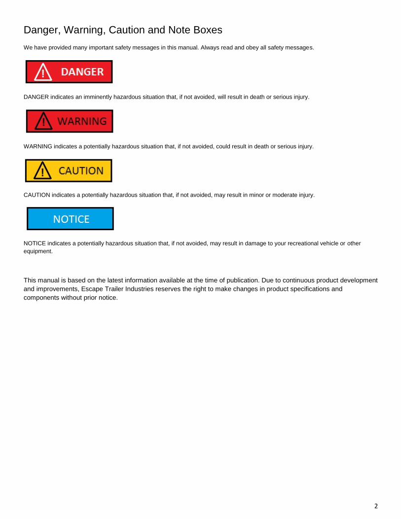
Danger, Warning, Caution and Note Boxes
We have provided many important safety messages in this manual. Always read and obey all safety messages.
DANGER indicates an imminently hazardous situation that, if not avoided, will result in death or serious injury.
WARNING indicates a potentially hazardous situation that, if not avoided, could result in death or serious injury.
CAUTION indicates a potentially hazardous situation that, if not avoided, may result in minor or moderate injury.
NOTICE indicates a potentially hazardous situation that, if not avoided, may result in damage to your recreational vehicle or other
equipment.
This manual is based on the latest information available at the time of publication. Due to continuous product development
and improvements, Escape Trailer Industries reserves the right to make changes in product specifications and
components without prior notice.
3
Chapter 1: Warranty Information
As the owner of a new recreational vehicle, you are responsible for regular care and proper maintenance. Proper
maintenance will help avoid situations where the Manufacturer’s Limited Two-Year Warranty will not cover items due to
neglect. Maintenance services should be performed in accordance with this manual, as well as the corresponding
manufacturers’ warranties on components included within your trailer.
Owner’s Responsibilities
1. Proper care and maintenance as outlined in this manual and the corresponding component warranty package 2. Returning your vehicle to an authorized service center for any repairs or service that is required 3. Reviewing the information contained within this manual and all supplied component information
Limited Two-Year Warranty
COVERAGE:
Escape Trailer Industries (‘ETI’) warranty covers this recreational vehicle (‘RV’) for a period of two (2) years from the date
of purchase by the first retail owner. This limited warranty covers defects in materials and workmanship supplied by and
attributable to ETI’s manufacturing and assembly of the RV, when the RV is used for its intended purposes of recreational
camping.
IN ADDITION, SINCE IT IS REASONABLE TO EXPECT THAT THE RV WILL NEED SOME SERVICE DURING THE
WARRANTY PERIOD, THIS WARRANTY DOES NOT EXTEND TO FUTURE PERFORMANCE. IT ONLY SETS FORTH
WHAT ETI WILL DO AND DOES NOT GUARANTEE ANYTHING ABOUT THE RV FOR ANY TIME PERIOD.
ETI is not responsible for any undertaking, representation, service agreement, or warranty beyond what is expressly set
forth in this Limited Warranty.
DISCLAIMERS, LIMITATIONS, AND EXCLUSIONS:
ESCAPE TRAILER INDUSTRIES WILL NOT BE RESPONSIBLE OR LIABLE FOR INCIDENTAL OR CONSEQUENTIAL
DAMAGES OF ANY KIND OR NATURE THAT RESULT FROM ANY DEFECT IN THE RECREATIONAL VEHICLE. THE
DISCLAIMER OF CONSEQUENTIAL DAMAGES IS NOT DEPENDENT UPON THE WARRANTY FULFILLING ITS
ESSENTIAL PURPOSE.
WHAT IS NOT COVERED - THIS LIMITED WARRANTY SHALL NOT APPLY TO:
• Routine maintenance including, without limitation, caulking, re-caulking and waxing of the body of the RV, tightening
screws, brake squeak/lock-up/adjustment, latches, locks, combustion systems, changing fuses and maintaining the air
conditioning and heating systems;
• Adjustments to all doors, drawers, locks, latches, awnings and window treatments beyond 90 days after retail sale.
• Equipment, products, components, appliances, or accessories not manufactured by ETI;
• Recreational vehicles used for business, rental, commercial, residential, or disaster relief purposes, or any purposes
other than recreational travel and family camping;
• Recreational vehicles which are not originally purchased through ETI or those purchased through auction, repossession,
salvage or an otherwise damaged or distressed condition;
• Damage or loss caused in whole or in part by the misuse, abuse, neglect, theft, vandalism, product modification,
improper customer or dealer installation, improper stowing of equipment, overloading or improper balancing of the load,
low or high voltage, unauthorized repair or failure to follow instructions supplied with the recreational vehicle;
4
• Damage or loss caused in whole or in part by the unauthorized attachments, modifications or alterations to the structure,
body, pin box, or frame of the RV including but not limited to trailer hitches for towing;
• Any fading or die lot changes of fabrics or carpet;
• Design defects; Redesign/Re-construction of any part of the RV; or anything related to wheel or axle alignment;
• Rust or corrosion due to the environment; and any broken glass damage;
• Damage or loss caused in whole or in part by animals, exposure to natural or atmospheric elements, corrosive
chemicals, ash or fumes generated or released by vehicles, collision, road hazards, rock chips, condensation, or any
other source;
• Damage or loss caused in whole or in part by the willful or negligent acts of the driver of the vehicle pulling the RV, an
accident involving the RV, or the condition of any road surface;
• Damage or loss to the RV caused in whole or in part by the tow vehicle selected by the owner, owner’s operation or use
of the tow vehicle, improper selection or installation of towing hitch on tow vehicle, weight distribution, sway control or
equalizer equipment, or damage to the owner’s tow vehicle;
• Any injury, loss or damage due to mold or fungi; and
• Any RV licensed, registered, or primarily used outside Canada or the USA.
Manufacturing defects reported to Escape Trailer Industries within two years after original retail delivery of your new
Travel Trailer will be corrected without charge and within reasonable times.
Owner Responsibility
It is the responsibility of the owner to maintain the recreational vehicle as described in the Care and Maintenance section
of the Owner’s Manual including taking whatever preventative measures necessary to maintain the exterior sealants of the
unit and to prevent foreseeable secondary moisture or water damage to the unit from rain, plumbing leaks, condensation
and other natural accumulation of water in the unit. Examples of secondary damage include, but are not limited to, stained
upholstery, flooring or blinds, mold formation and growth, furniture, cabinetry or floor deterioration, etc. Mold is a natural
growth given certain environmental conditions and is not covered by the terms of the Warranty.
How To Obtain Warranty Service
Your continued satisfaction with your travel trailer is of utmost importance to Escape Trailer Industries. Please follow
these steps for fast, efficient warranty service.
Warranty service requests must be made within the warranty period and should ordinarily be initiated by Escape Trailer
Industries.
1. Inspect your travel trailer thoroughly to determine exactly what service is required. 2. Contact Escape Trailer Industries by phone or email with this information. 3. If Escape Trailer Industries is not within a reasonable proximity for service, Escape Trailer Industries will work with a reputable service center near the customer.
Unit Information Packet
In addition to this Owner’s Manual, a unit information packet is located within your new recreational vehicle. Inside the
packet are product manuals and information on systems and equipment in the trailer. Individual product warranty
registrations accompany this information and should be completed and mailed promptly.
5
Get To Know Your Unit Before Heading Out
Throughout the manufacturing process, your recreational vehicle has undergone rigorous testing of all the systems and
has been inspected by qualified inspectors. As the owners, however, you will be the first to camp and extensively use
every system. Escape Trailer Industries wants the first camping experience to be a happy one and recommends a “Trial
Camping Experience” before heading out. Plan a weekend in the yard or driveway and really camp in your unit.
By camping consistently for several days in your unit, you will have the opportunity to use and become accustomed to the
systems within your unit and find out what items are needed/not needed while camping. Note any questions that arise,
difficulties encountered or problems that occur. After your trial, call or email Escape Trailer Industries and ask any
questions that have arisen. Getting to know your unit before the first adventure can save a lot of frustration and leave
more time for fun!
NOTE: Your Escape Trailer Industries Warranty covers warrantable repairs that are performed by an authorized Escape
Trailer Industries dealer at their service center or facility only. It is important for the owner to know that if you are unable to
bring your unit in for repairs, Escape Trailer Industries is not responsible for any costs incurred for the service call charge,
or time accrued to come out to your unit. Your unit is a recreational vehicle and not intended, nor manufactured, as a
permanent residence. Long-term or full-time occupancy may lead to premature deterioration and may, under the terms of
the warranty, constitute misuse and reduce your warranty protection.
6
Chapter 2: Effects of Prolonged Occupancy
Your recreational vehicle was designed primarily for recreational use and short-term occupancy. If you expect to occupy
the coach for an extended period, be prepared to deal with condensation and the humid conditions that may be
encountered. The relatively small volume and tight compact construction of modern recreational vehicles means that the
normal living activities of even a few occupants will lead to rapid moisture saturation of the air contained in the trailer and
the appearance of visible moisture, especially in cold weather.
Just as moisture collects on the outside of a glass of cold water during humid weather, moisture can condense on the
inside surfaces of the recreational vehicle during cold weather when relative humidity of the interior air is high. This
condition is increased because the insulated walls of a recreational vehicle are much thinner than house walls. Estimates
indicate that a family of four can vaporize up to three gallons of water daily through breathing, cooking, bathing and
washing.
Unless the water vapor is carried outside by ventilation or condensed by a dehumidifier, it will condense on the inside of
the windows and walls as moisture or in cold weather as frost or ice. Appearance of these conditions may indicate a
serious condensation problem. When you recognize the signs of excessive moisture and condensation in the trailer,
action should be taken to minimize their effects.
Ventilation, Condensation and Moisture Management
The following steps should be taken to aid in eliminating internal moisture condensation:
Interior Care of Your RV
Signs of excessive moisture can be obvious, such as water droplets forming on surfaces or wet areas around cushions or
mattress. Conversely, signs of excess moisture can be subtle, such as condensation forming on metal surfaces. When
symptoms appear it is important to timely determine the cause of the excess moisture and take appropriate corrective
action to prevent moisture related damage.
Control Relative Humidity
Monitoring and controlling relative humidity within the RV is one of the most important steps to minimize the risk for
moisture-related damage. Ideally, relative humidity should be at 60% or less. Relative humidity can be monitored utilizing
a portable hygrometer, a small device that measures temperature and relative humidity. Hygrometers are available at
electronics or building supply stores for approximately thirty dollars ($30).
Use exhaust fans, the air conditioner, and/or a portable dehumidifier to manage moisture inside the RV to maintain
relative humidity at 60% or less. In cold climates, relative humidity may need to be at 35% or less to avoid window
condensation issues.
If the RV is used the majority of the time in a hot-humid climate, it may be difficult to keep relative humidity below 60%. A
dehumidifier will help, but it is important to check the condensation (water) collection bucket regularly or discharge the
condensation (water) directly to a drain.
Avoid Drastic Thermostat Setbacks
Cooler surface temperatures increase the potential for condensation and surface mold growth. To minimize the
opportunity for condensation to form on interior surfaces, maintain a comfortable temperature in your RV, and avoid
nighttime setbacks of 10 degrees or more. Drastic setbacks that reduce the indoor air temperature quickly can increase
the chance for airborne moisture to condense on cool surfaces such as windows. If you are away from your RV for an
extended number of days, we recommend that you do not set the temperature back without taking other measures to
manage relative humidity, including operating a dehumidifier with a continuous drain.
7
Manage Window Condensation
Window condensation issues can be identified by water or ice build-up, usually at the base of the window. The majority of
these problems can be addressed by managing moisture generated inside the RV. Minor condensation issues are not
unusual, especially for RVs used in colder climates. The key is to manage this small amount of moisture if evident by
wiping the surface, and as discussed above, maintaining a reasonable relative humidity within the unit.
To help minimize window condensation, use exhaust fans vented to the outside, avoid drastic changes in thermostat
settings, do not use ‘vent-free’ heaters and use window coverings wisely. For example, make sure to open curtains or
blinds during the day to allow air to circulate and warm the window surface.
Storage and Other Isolated Areas Within the RV
Storage areas are more difficult to condition since the areas are isolated from the main body of the RV. The surfaces of
these areas are more at risk for condensation and surface mold growth. To minimize this risk, clean storage areas
regularly, and allow an air space between stored items and the exterior wall to promote air circulation.
During prolonged use of the recreational vehicle in very cold weather, closet and cabinet doors should be left partially
open in order to ventilate the interiors of storage compartments built against exterior walls. The air flow will aid in warming
exterior walls, assist in reducing or eliminating condensation, and prevent possible ice formation.
Use of Unvented Combustion Equipment
Unvented combustion equipment, such as propane stovetops, are a source of moisture within the RV. For every gallon of
fuel consumed, approximately one gallon of water vapor is evaporated into the air. Whenever possible, operate an
exhaust fan in combination with the use of any unvented combustion appliance within the RV. Water vapor and other
combustion by-products should be vented to the exterior of the RV. The RV owner should strictly follow use and
maintenance instructions for safe operation of any combustion equipment, particularly unvented equipment.
DO NOT HEAT THE TRAILER WITH RANGE OR OVEN.
(WARNING Continued)
In addition to the dangers of toxic fumes and oxygen depletion which makes heating with the range or oven very dangerous, open
flames add moisture to the interior air, increasing condensation. Do not use an air humidifier inside the trailer.
Use of Your RV
It is important to remember that the square footage of an RV is significantly less than that of a single family residence.
This fact alone will elevate the relative humidity because there is less volume of air to help absorb or dissipate the
humidity. For example, showering and cooking create a lot of humidity in a small area. In these instances, use of an
exhaust fan and opening windows should reduce the relative humidity, particularly when living in the RV for an extended
period.
Ventilate your recreational vehicle regularly by partially opening roof vents and one or more windows. Use vents when
using the range or shower. While this venting will increase the furnace heating load, it will greatly reduce, or eliminate,
water condensation. NOTE: Even when it is raining or snowing, ventilation air from outside will be far drier than interior air
and will effectively reduce condensation.
8
Remember to run the range vent fan when cooking and the bath vent fan (or open bath vent) when bathing to carry water
vapor out of the trailer. Avoid excessive steam resulting from boiling water or use of hot water. Remove snow or water
from shoes or boots before entering the trailer to avoid soaking floor.
Also avoid drying overcoats or other clothes inside the trailer
Exterior Care Of Your RV
The exterior shell of the RV is the primary weather and moisture barrier. Over the life of the RV, the shell will require
regular care and maintenance in accordance with the owner’s manual. The shell includes the roof, sidewalls, windows,
doors, and under-floor. Particular attention needs to be devoted to these components in order to maintain a tight barrier
against bulk water intrusion.
The shell should be inspected periodically for cracks, gaps, and condition of sealants in accordance with your owner’s
manual. Areas that require maintenance should be resealed utilizing a similar, high quality sealant used by the
manufacturer.
Storage of Your RV
During those periods when your RV is not in use, care must be taken to ensure moisture sources are addressed. Ideal
storage of your RV would be in an enclosed climate controlled environment. When this is not possible, the following steps
should be taken to ensure moisture is controlled:
• Turn off all water sources;
• Turn off all combustion appliances;
• Drain the water tank(s);
• Drain the water heater;
• Open all closets, cabinet doors and drawers;
• Close all windows and entrance doors;
• Open a vent or a window enough to allow for some limited ventilation air flow, but not so far as to allow snow or rain to
enter;
When storing the RV in high humidity climates (ambient relative humidity is greater than 60% year round), add a
dehumidifier drained to exterior to control humidity inside the RV during storage.
Wet Areas
Areas that are exposed to water spills or leaks should be dried as soon as possible and definitely within 24-48 hours.
Drying areas quickly minimizes the chance for moisture damage and possible mold growth, which can begin to form
colonies in 24-48 hours. A variety of methods can be used to help the drying process:
• Remove excess water with an extraction vacuum.
• Use a dehumidifier to aid drying.
• Because moisture is key to mold issues, treat all signs of condensation and spills seriously and deal with promptly.
Failure to deal with a moisture issue promptly may cause more severe issues where none initially existed, or may make a
small problem much worse.
9
• Be sure to understand and eliminate the source of moisture accumulation as a part of the clean-up. Otherwise, the same
issues will simply recur.
• Small amounts of mold should be cleaned as soon as they appear. Small areas of mold should be cleaned using a
detergent/soapy solution or an appropriate household cleaner. Gloves should be worn during cleaning. The cleaned area
should then be thoroughly dried. Dispose of any sponges or rags used to clean mold.
Use A Dehumidifier
During prolonged and continuous usage of the trailer, a dehumidifying appliance may be more comfortable and effective
in removing excess moisture from interior air. While use of a dehumidifier is not a cure-all, operation of a dehumidifier will
reduce the amount of outside air needed for ventilation. Thus, the heating load on the furnace will be reduced and the
interior will be less drafty.
Remember, your trailer is not designed, nor intended, for permanent housing. Use of this product for long-term or permanent
occupancy may lead to premature deterioration of structure, interior finishes, fabrics, carpeting and drapes. Damage or deterioration
due to long-term occupancy may not be considered normal and may, under the terms of the warranty, constitute misuse, abuse or
neglect and may therefore reduce the warranty protection.
USE OF KEROSENE OR OTHER AFTERMARKET SPACE HEATERS IS NOT RECOMMENDED AND IS AT YOUR OWN RISK.
SUCH HEATERS MAY DISCHARGE MOISTURE AND GASES FROM COMBUSTION INTO YOUR TRAILER OR CAUSE
EXCESSIVE INDOOR HUMIDITY. SUCH HEATERS MAY ALSO CAUSE A FIRE, DEPLETE
(WARNING Continued)
OXYGEN, OR RELEASE CARBON MONOXIDE OR OTHER HARMFUL GASES WHICH CAN CAUSE SERIOUS INJURY OR
DEATH.
10
Chapter 3: Towing and Leveling
Your Travel Trailer — a True Recreational Vehicle
Your travel trailer is a vacation home on wheels. It is carefully designed for every normal recreational use and activity
including travel.
Escape Trailer Industries strongly recommends that your recreational vehicle not be occupied while traveling. It is unsafe
and illegal to ride in a travel trailer. Your recreational vehicle is not equipped with seat belts or other highway safety
provisions commonly required for passenger vehicles. Also in some emergency conditions cargo could shift suddenly
resulting in injury or even death.
Do’s and Don’ts For Equipment Selection
• Be sure the tow vehicle is large enough for your trailer or fifth wheel and has the needed power and heavy duty running
gear. It must be rated by its manufacturer to tow the gross weight, and to carry the hitch weight of the fully loaded trailer or
fifth wheel.
• Use a weight distributing hitch rated not less than the trailer Gross Vehicle Weight Rating (GVWR). Follow the tow
vehicle and hitch manufacturers' instructions. Install the hitch ball as close as practical to the rear bumper to minimize rear
overhang. (Does not apply to fifth wheels.)
• Do not over-tighten the weight distributing hitch spring bars. Follow the instructions of the hitch manufacturer. When in
doubt, use the less tight spring bar setting. (Does not apply to fifth wheels.) For more information, see “Hitches & Towing”
on page 17.
• Do not add any type of adapter to the fifth wheel king pin, such as a goose neck adapter. Lengthening the fifth wheel
hitch by means of an adapter will transfer greater loads to the chassis, possibly more than the chassis is designed for, and
could result in structural damage. Damage that is a direct result of the use of such an adapter is not covered by Escape
Trailer Industries warranty.
• Use a brake controller that automatically applies the brakes in proportion to the tow vehicle brakes and also has a hand
control for applying the trailer brakes only.
• Adjust the brake controller so that the brakes of the trailer come on as quickly as possible
without sliding the tires of the loaded trailer during strong braking.
• Inflate the rear tires of the tow vehicle to their maximum cold pressure. (See the maximum pressure rating on the tire
sidewalls.)
• Load heavy objects and goods as close to the trailer axle(s) as possible. Do not place heavy objects on the rear bumper
or on the tongue.)
Towing Guidelines
Weight distribution is an important factor when loading your fifth wheel and travel trailer. A recreational vehicle with the
cargo distributed properly will result in efficient, trouble-free towing. Loading the coach as evenly as possible and then
weighing the loaded RV can accomplish proper weight distribution. Keep heavier items as low as possible and distribute
evenly (front to back and side to side). Securing your possessions can prevent damage from shifting during towing and
maintain the weight distribution balance achieved during preparation for travel.
You must not exceed the GVWR or GAWR of the unit (see definitions). To verify GVWR, total the loaded hitch and axle
weights. If this total exceeds GVWR, you must remove items until the vehicle weight is within this limit. You can verify that
11
the coach’s axles are not overloaded by comparing the loaded axle weight with the GAWR. If the reading is above this
limit, redistribute the item load.
Finally, make sure the pin weight of the loaded fifth wheel falls within the limits of the tow vehicle.
NEVER RIDE IN YOUR RECREATIONAL VEHICLE.
Passengers are not permitted in the recreational vehicle while it is in motion.
Tow Vehicle Disclaimer
In connection with the use and operation of Escape Trailer Industries recreational vehicles, Escape Trailer Industries customers and
owners of Escape Trailer Industries recreational vehicles are solely responsible for the selection and proper use of tow vehicles. All
customers should consult with a motor vehicle manufacturer or dealer concerning the purchase and use of suitable tow vehicles for
Escape Trailer Industries products. Escape Trailer Industries further disclaims any liability with respect to damages which may be
incurred by a customer or owner of Escape Trailer Industries recreational vehicles as a result of the operation, use or misuse of a tow
vehicle. NOTE: ESCAPE TRAILER INDUSTRIES’S WARRANTY DOES NOT COVER DAMAGE TO THE RECREATIONAL VEHICLE
OR THE TOW VEHICLE AS A RESULT OF THE OPERATION, USE OR MISUSE OF THE TOW VEHICLE.
Weight Ratings - Definitions
GVWR (Gross Vehicle Weight Rating)
The maximum permissible weight of this coach when fully loaded. It includes all weight at the unit’s axle(s) and tongue or
pin.
UVW (Unloaded Vehicle Weight)
The weight of this trailer as manufactured at the factory. It includes all weight at the trailer axle(s) and tongue or pin. The
UVW does not include cargo or fresh water.
CCC (Cargo Carrying Capacity)
This is the maximum amount of cargo you can safely add to this vehicle. Cargo carrying capacity is calculated with all
manufacturer installed equipment, full propane tanks and full fresh water tank. We strongly recommend weighing your
loaded RV prior to travel as described in this manual beginning on page 15 to ascertain you are within all weight
limitations.
GAWR (Gross Axle Weight Rating)
The maximum allowable weight that an axle system is designed to carry, as measured at the tire/ ground interfaces.
12
Weight Rating - Label
The information on the weight ratings is contained on the Transport Canada label: This label contains the Vehicle
Identification Number (VIN) / Serial Number for the vehicle rated. These ratings are specific for each fifth wheel and travel
trailer manufactured. Use only the ratings found on these labels.
The label is required to be on the exterior road-side near the front corner of the vehicle.
This label identifies the Steps for Determining Correct Load Limit
Locate the cargo carrying capacity on the RV Trailer Cargo Carrying Capacity Label.
When loading your cargo, be sure it is distributed evenly to prevent overloading front to back and side to side. Heavy
items should be placed low and as close to the axle positions as reasonable. Too many items on one side may overload a
tire.
All objects should be held securely in place. Loose items can cause interior damage and erratic trailer movements. They
can even be a hazard to others if they fall out. Load shifts can affect driving and handling enough to cause serious,
unexpected danger. Inspect tie-downs and fastenings, as well as the load, at regular intervals every hour or two,
depending on roads, curves, hills, and speed. The first check should be made within a half hour after the trip is started or
after the first 25 miles, since some initial settling is likely.
If you are going on a long trip, take a “shakedown cruise” of a few miles the weekend before you leave. This will test your
load, safety equipment, hitch, and might reveal things you missed or forgot. By getting everything in order before you
leave home, you can prevent delays and annoyances that could take the fun out of your trip.
Many owners place luggage, camping equipment, bicycles, and other items in the travel trailer. The weight of everything
put on or in a trailer, whether temporarily or permanently built-in, must be included in figuring the total load.
How Overloading Affects Your RV and Tires
The results of overloading can have serious consequences for passenger safety. Too much weight on your vehicle's
suspension system can cause spring, shock absorber, or brake failure, handling or steering problems, irregular tire wear,
tire failure or other damage.
If insufficient weight is placed on the hitch, the trailer will tend to move from side to side, or to “fishtail”, which can be
dangerous. Towed trailers are designed to have proper weight on the hitch for balance when the trailer floor is level.
An overloaded vehicle is hard to drive and hard to stop. In cases of serious overloading, brakes can fail completely,
particularly on steep hills. The load a tire will carry safely is a combination of the size of tire, its load range, and
corresponding inflation pressure.
It is the air pressure that enables a tire to support the load, so proper inflation is critical. Under-inflated tires can show
excessive signs of wear, cause reduced handling capability, overheat, suffer belt separation or fail completely.
Tires should never be inflated beyond the maximum cold inflation pressure molded into the sidewall of the tire. See
chapter 10 for additional information.
WHILE CARGO CAN BE ADDED UP TO THE MAXIMUM CARGO CARRYING CAPACITY, CARE MUST ALSO BE EXERCISED TO
NEVER EXCEED THE GAWR, GVWR, NOR THE MAXIMUM LOAD RATINGS FOR YOUR VEHICLE OR HITCH.
13
OVERLOADING OR IMBALANCED LOADING OF YOUR TRAVEL TRAILER CAN AFFECT HANDLING OR CAUSE AN ACCIDENT
THAT COULD RESULT IN SERIOUS INJURY OR DEATH.
EXCESSIVE LOADS AND/OR UNDER-INFLATION CAUSE TIRE OVERLOADING AND, AS A RESULT, ABNORMAL TIRE FLEXING
OCCURS. THIS SITUATION CAN GENERATE AN EXCESSIVE AMOUNT OF HEAT WITHIN THE TIRE. EXCESSIVE HEAT MAY
LEAD TO TIRE FAILURE.
WHEEL SEPARATION CAN OCCUR! EXCEEDING THE GVWR AND GAWR RATINGS FOR YOUR UNIT COULD RESULT IN
SERIOUS DAMAGE TO THE SUSPENSION, FRAME OR OTHER COMPONENTS.
Weighing Your Unit
The total weight, including liquids, groceries, clothing, etc. must not exceed the Gross Vehicle Weight Rating (GVWR)
stated on the Transport Canada Label on your Trailer. The total load on the front and rear wheels must not exceed the
respective Gross Axle Weight Rating (GAWR) shown on the label.
Travel Trailer
• Drive the loaded trailer onto the scale, making sure that the hitch will be the only contact point with the scale after
unhooking. Unhook and drive the tow vehicle off the scales. Level the trailer and record hitch weight.
• Hookup to the trailer and pull forward on the scales until only the trailer axles are on the scale. Level the trailer and
record the axle weight.
• To determine total trailer weight, add the hitch weight plus axles.
1. The total trailer weight (dry weight of standard unit plus options added plus water stored plus liquid wastes in holding
tanks plus all cargo) must not exceed the GVWR stated on the label of your trailer.
2. The total load of your fully loaded trailer on the tires when connected to the towing vehicle must not exceed the
combined total Gross Axle Weight Rating (GAWR). The GAWR is stated on the Transport Canada Label.
3. The hitch weight must not exceed your hitch manufacturer’s recommendation. It should be 10 to 15 percent of the total
travel trailer weight.
4. Equalize side to side loading. Store heavy objects on or near the floor.
5. Avoid towing with waste holding tank(s) full or partially full. If unavoidable, drive slowly until one or both tanks can be
dumped.
6. Keep water tank either completely full or empty when towing to avoid the shifting of weight of a partially filled tank.
14
Fifth Wheel
• Pull onto the scale until all tow vehicle tires are on the scale. Record this weight (vehicle + pin weight of trailer).
• Pull forward until only the trailer wheel tires are on the scale. Record the axle weight.
• Pull off the scale, unhook the trailer and weigh the truck by itself.
1. The total load on the trailer tires when connected to the towing vehicle must not exceed the combined total Gross Axle
Weight Rating (GAWR). The GAWR is stated on the Transport Canada Label.
2. Calculate the pin load by subtracting the weight of the truck (without trailer attached) from the weight of the truck with
the trailer attached. The pin weight thus obtained should be 19% - 25% of the total trailer weight for good towing. The pin
weight must not exceed the maximum allowable for your truck. (Consult truck manufacturer’s specifications for your
vehicle).
3. Calculate total weight by adding pin weight obtained in step two to axle weight from step one. This total must not
exceed the GVWR stated on the Transport Canada Label.
These procedures should be repeated whenever there is any change in vehicles or loading to ensure that you do not
exceed the ratings.
Storage
The storage facilities in your trailer have been designed to remain secure while in motion. Exterior compartments have
key operated locks. Drawers have spring catches installed; extra effort is necessary when pulling drawers open to release
the catch. When storing articles:
• Always keep tools and equipment stored in areas where they will not shift while traveling.
• Wherever possible, place heavy articles in storage compartments which are low and near the axles for better weight
distribution.
• Pack articles carefully in the storage compartments to minimize shifting. If necessary, use straps to prevent movement.
• Be sure liquid containers are capped and cannot tip or spill. Secure all glass containers and dishes before traveling.
• Exterior storage compartments may not be watertight in all climate conditions. Carry any articles which could be
damaged by water inside the trailer.
OUTSIDE STORAGE COMPARTMENTS ARE NOT SEALED. THEY ARE VENTED ENCLOSURES, AND ARE ACCESSIBLE FROM
INSIDE THE TRAILER. THEREFORE, DO NOT STORE FLAMMABLE, VOLATILE LIQUIDS, HAZARDOUS CHEMICALS OR
EQUIPMENT IN THESE AREAS.
Hitches and Towing
Hitching your trailer to the tow vehicle will become routine with experience. Make it a habit to examine all hitch
components before hitching the trailer. If you have a conventional ball hitch, check for cracked or bent parts, cracked
welds, deformed or stripped bolts. Inspect the spring bars and chains. Be sure the ball is tight and well lubricated. Check
the trailer tongue for cracks. Be sure the ball locking device works freely. Inspect the safety chains. If you find a defect in
any hitch component, correct it before towing the trailer.
15
If you have a fifth wheel trailer, check all truck-mounted hitch components. Check for worn, cracked, or bent parts. Be
sure the locking device works properly. Inspect the pin box assembly on the trailer. Check the king pin. If you find any
defective components, repair or replace them before towing. Be sure all moving parts of the hitch are well lubricated.
Fifth Wheel
1. Adjust the landing gear jacks until coach is at a level for hooking to the tow vehicle.
2. Place wheel chocks behind fifth wheel’s tires.
3. Lower the tailgate on truck.
4. Release the fifth wheel lock handle on the tow vehicle.
5. Line up the tow vehicle so the fifth wheel will accept the kingpin.
6. Check clearances. You may need to close truck tail gate, when far enough past kingpin to do so, prior to fully engaging
fifth wheel hitch.
7. Back truck slowly until kingpin engages the fifth wheel and automatically locks.
8. Ensure the lock is closed, and locked in closed position.
9. Connect the power seven-way cord between the tow vehicle and the fifth wheel.
10. Connect the emergency breakaway switch cable.
11. Completely raise the landing gear.
12. Remove and store the wheel chocks.
13. Check the tire pressure while the vehicle tires are cold.
14. Re-torque the lug nuts. Refer to “Wheel Nut Torque”.
Travel Trailers
Before attempting to hitch up your trailer, read the instructions provided by the manufacturer of the hitch. Escape Trailer
Industries trailers accept a 2-inch ball. The following instructions apply in most cases. If the instructions provided with your
hitch are different from these instructions, follow those of the hitch manufacturer:
1. Place wheel chocks behind the travel trailers tires.
2. Turn the tongue jack crank clockwise. This will raise the tongue and coupler. Raise the tongue sufficiently to clear the
hitch ball on the tow vehicle.
3. Back the tow vehicle until the hitch ball is under the hitch ball socket. If you are working alone, a backing aid mirror may
be helpful. Set the parking brake.
4. The coupler latch locking lever on the tongue should be fully open. Lower the tongue jack until the ball is firmly seated
in the socket. Close the coupler latch and secure it with a locking pin or bolt.
5. Raise the tow vehicle and trailer with the tongue jack high enough to allow room to install the hitch spring bars. (The
tow vehicle will come up with it if the coupler is properly latched).
6. Attach the spring bars according to the hitch manufacturer’s instructions.
7. After adjusting the spring bars, raise the jack off the ground to its highest level. Note that the trailer must be relatively
level front to back. Tilt in either direction must be kept to an absolute minimum. Having the front lower than the rear
reduces towing stability on tandem axle trailers.
16
8. Connect all safety chains. Safety chains are extremely important to protect your investment as well as other people’s
lives and property. As a trailer owner, it is your responsibility to be familiar with these devices and their correct use. The
hitch on your tow vehicle must be equipped with two chain attachment eyes on each side of the vehicle’s centerline. Both
chains should be the same length and crossed under the trailer’s tongue to hold the tongue off the ground if the trailer
accidentally becomes uncoupled.
9. Connect the emergency breakaway switch cable.
10. Plug in the 12-volt 7-way electrical connector.
11. Check stop lights, turn lights, running lights, and electric brakes before driving off. See ELECTRICAL SYSTEM section
in this manual for details of the electrical system and wiring.
12. Remove and store the wheel chocks.
13. Reverse the procedure for unhitching, placing wheel chocks at the front and rear of the trailer tires prior to uncoupling
the trailer from the tow vehicle to ensure the trailer does not roll away when the coupling is released.
FOLLOW THE INSTRUCTIONS OF THE HITCH MANUFACTURER FOR ADJUSTING THE WEIGHT DISTRIBUTING HITCH.
OVERTIGHTENING OF HITCH SPRING BARS WILL REDUCE CORNERING AND STOPPING ABILITY AS WELL AS TOWING
STABILITY.
NEVER ATTACH SAFETY CHAINS TO THE HITCH BALL OR ANY REMOVABLE PART OF THE HITCH.
DO NOT CONNECT THE BREAKAWAY SWITCH LANYARD TO THE HITCH BALL OR ANY REMOVABLE PART OF THE HITCH.
Before Towing
• Disconnect and securely store all park connections.
• Close and secure all doors, windows, awnings and roof vents.
• Return the Entry step to the travel position.
• Refer to the “Pre-Travel Checklist” located in the Appendix.
Towing
Towing a recreational vehicle can be enjoyable and worry-free if special attention toward safety is applied every time you
hit the road. Before heading out on your first camping trip, practice turning, stopping and backing in low traffic areas or
large parking lots. In time, traveling with a recreational vehicle in tow will be as easy as driving the family car.
17
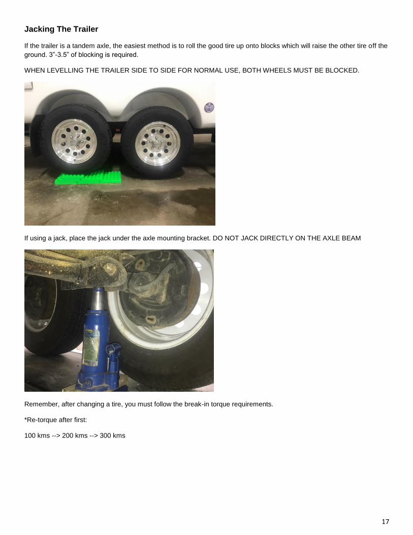
Jacking The Trailer
If the trailer is a tandem axle, the easiest method is to roll the good tire up onto blocks which will raise the other tire off the
ground. 3”-3.5” of blocking is required.
WHEN LEVELLING THE TRAILER SIDE TO SIDE FOR NORMAL USE, BOTH WHEELS MUST BE BLOCKED.
If using a jack, place the jack under the axle mounting bracket. DO NOT JACK DIRECTLY ON THE AXLE BEAM
Remember, after changing a tire, you must follow the break-in torque requirements.
*Re-torque after first:
100 kms --> 200 kms --> 300 kms
18
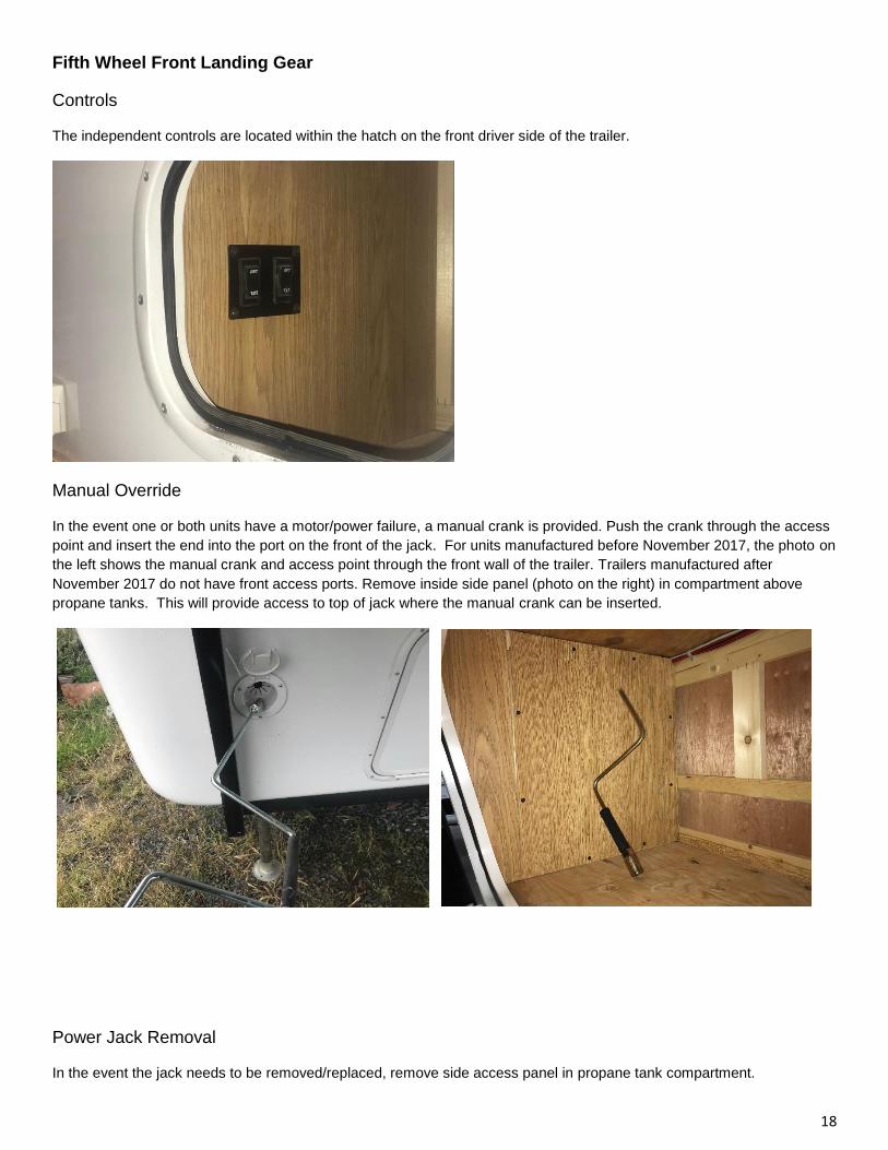
Fifth Wheel Front Landing Gear
Controls
The independent controls are located within the hatch on the front driver side of the trailer.
Manual Override
In the event one or both units have a motor/power failure, a manual crank is provided. Push the crank through the access
point and insert the end into the port on the front of the jack. For units manufactured before November 2017, the photo on
the left shows the manual crank and access point through the front wall of the trailer. Trailers manufactured after
November 2017 do not have front access ports. Remove inside side panel (photo on the right) in compartment above
propane tanks. This will provide access to top of jack where the manual crank can be inserted.
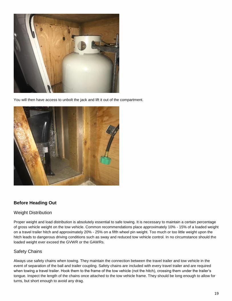
Power Jack Removal
In the event the jack needs to be removed/replaced, remove side access panel in propane tank compartment.
19
You will then have access to unbolt the jack and lift it out of the compartment.
Before Heading Out
Weight Distribution
Proper weight and load distribution is absolutely essential to safe towing. It is necessary to maintain a certain percentage
of gross vehicle weight on the tow vehicle. Common recommendations place approximately 10% - 15% of a loaded weight
on a travel trailer hitch and approximately 20% - 25% on a fifth wheel pin weight. Too much or too little weight upon the
hitch leads to dangerous driving conditions such as sway and reduced tow vehicle control. In no circumstance should the
loaded weight ever exceed the GVWR or the GAWRs.
Safety Chains
Always use safety chains when towing. They maintain the connection between the travel trailer and tow vehicle in the
event of separation of the ball and trailer coupling. Safety chains are included with every travel trailer and are required
when towing a travel trailer. Hook them to the frame of the tow vehicle (not the hitch), crossing them under the trailer’s
tongue. Inspect the length of the chains once attached to the tow vehicle frame. They should be long enough to allow for
turns, but short enough to avoid any drag.
20
Breakaway Switch
The breakaway switch is another safety device as it provides a means of automatically slowing and stopping your RV if it
should become detached during traveling. The cable from the break-away switch should be attached to the tow vehicle so
that it remains connected in the event the trailer coupling detaches from the hitch ball. The breakaway switch is powered
from the RV 12 Volt battery. If separation occurs the pin is pulled out of the switch and current from the RV battery is
applied to the trailer brakes. See electrical section for testing breakaway switch.
DISCONNECT THE UNIT FROM THE SEVEN-WAY TOW VEHICLE CORD PRIOR TO TESTING THE BREAKAWAY SWITCH.
FAILURE TO DO SO MAY CAUSE DAMAGE TO THE BRAKE CONTROLLER.
Tire Pressure
Maintaining proper tire pressure is another key to safety. The cold inflation pressure for each tire is located on the Canada
Transport Label. Cold inflation pressure refers to the pressure in the tire prior to traveling. Always check your tire pressure
before traveling. Under-inflated tires will cause excessive sidewall flexing and produce extreme heat, leading to early tire
failure and possible loss of control. Overinflated tires can cause uneven tire wear and also lead to early failure. More
information on tires and maintenance can be found in the Care and Maintenance section.
• Most tires may naturally lose air over time, up to several PSI per month in some conditions.
• Tires can lose air suddenly if you drive over a pothole or other object or if you strike the curb when parking.
• With radial tires, it is usually not possible to determine under-inflation by visual inspection.
Level Towing
Having the tow vehicle and recreational vehicle level with each other will help improve tow-ability as well as safe driving. A
hitch that is too low can cause the front of the trailer to drag. A hitch that is too high can cause the rear of the trailer to hit
those high spots in the road.
Lights
Check all electrical connections to ensure all lights on the tow vehicle and travel trailer are functioning properly. The brake
lights, hazards and turn signals should be in synchronization with the tow vehicle.
Tire Safety Tips (Also see Chapters 9 &10)
Preventing Tire Damage
• Slow down if you have to go over a pothole or other objects in the road.
• Do not run over curbs or other foreign objects in the roadway, and try not to strike the curb when parking.
Tire Safety Checklist
• Check tire pressure regularly (at least once per month), including the spare.
• Inspect tires for uneven wear patterns on the tread, cracks, foreign objects, or other signs of wear or trauma.
• Remove bits of glass and foreign objects wedged in the tread.
21
• Make sure your tire valves have valve caps.
• Do not overload your vehicle.
• Drivers should always obey posted speed limits and reduce speeds when necessary based on vehicle, road, weather
and/ or traffic conditions.
• Vehicle speed, load and inflation pressures, all of which are within the control of the driver, are critical factors for the safe
and enjoyable operation of any vehicle.
• The tire designation ‘ST’ is the tire specifically for use by the trailer industry. Refer to the sidewall of the tire for specific
speed restriction for the tire. NEVER EXCEED THE TIRE RATING OR POSTED SPEED LIMITS.
Check tires for proper inflation and wheel lug torque to meet manufacturer’s specifications.
Level towing must be achieved through adjusting the hitch ball height on the tow vehicle. If after hitching up and adjusting the spring
bars (as described earlier in this manual) you find your vehicle out of level, measure the amount the vehicle is out of level and have a
qualified professional adjust the hitch ball height on the tow vehicle.
While Driving
Driving with a trailer in tow is different. Start out slowly, checking the traffic after signaling and being sure the road is clear.
Accelerate slowly and evenly, checking the mirrors frequently as you move into the proper lane. Try to drive with an
anticipation of problems that may occur way ahead and prepare for them, even though they may never happen. As a
motorist sharing the road, you are taller, heavier, longer and require more time and distance to stop. Weather and road
conditions will require adjustments to speed. Anticipate dips, gutters, and depressions in the road, slowing down well in
advance. These are the hardest jolts of any kind on your vehicle, hitch, recreational vehicle and items stored inside the
unit. Take dips and bumps slowly and be certain the trailer wheels have passed the point before accelerating.
Towing Speed
Reasonable speed is probably the greatest factor in safe and pleasant towing. Towing stability is increased and
emergency stopping distances are reduced with a reduction in speed. Reduce your driving speed substantially while
towing. Slow down for grades and turns. Towing stability is reduced downhill and around bends. With experience, you will
develop the special driving skills needed for safe trailer towing.
Stability in Towing
Swaying of a trailer behind a tow vehicle is an inherent characteristic of any combination of two or more vehicles. There
are numerous factors that affect towing stability that you as the owner have control over before you take your vehicle on
your first trip. And there are factors you need to be aware of while driving. We will address the most common factors in
this section.
Choose the right tow vehicle
There are several factors in choosing a tow vehicle that will affect towing stability. The best source of information to make
an informed decision on matching the tow vehicle to the travel trailer is your RV dealer and tow vehicle dealer. It would be
22
impossible for us in this manual to address all the factors or make specific recommendations, however, the following are
important considerations:
Weight of the tow vehicle — Generally the heavier the tow vehicle the better because it will be better able to dampen
lateral loads through the hitch as a result of wind or other factors.
Wheel Base — The longer the wheel base the better. This is especially a factor as the length of the travel trailer
increases. The greater the wheel base of the tow vehicle the better it will be able to dampen lateral loads through the hitch
as a result of wind or other factors.
Rear Overhang Distance — The rear overhang is the distance from the hitch ball to the center of the rear tow vehicle axle.
A shorter distance will result in a more stable ride.
Tire Sidewall Stiffness — The stiffer the sidewall of the tires the better the dampening of trailer sway. Weak tire sidewalls
or under-inflated tires will have an adverse effect on dampening.
Rear Suspension Stiffness — The stiffer the rear suspension the greater the ability of the tow vehicle to not be affected by
trailer sway. A soft tow vehicle rear suspension will allow movements of the trailer, transmitted through the hitch, to have a
greater effect on the tow vehicle. The stiffness of the rear suspension of the tow vehicle is one of the significant factors
affecting driver control.
TOW AT MODERATE SPEEDS ALLOWING FOR ADVERSE HIGHWAY AND WIND CONDITIONS. INCREASED SPEED REDUCES
TRAILER TOWING STABILITY, AND HANDLING AND STOPPING ABILITY.
DO NOT ATTEMPT TO STOP THE TRAILER SWAYING BY MAKING QUICK STEERING CHANGES, OR BY FORCEFULLY
APPLYING THE TOW VEHICLE BRAKES.
Trailer Loading
Trailer loading can have an effect on the towing stability. There are some general principles you can follow when loading
your trailer to keep trailer sway to a minimum.
Center of Gravity — The higher the center of gravity for a vehicle the less stable it will be in certain situations. Therefore,
when loading heavy items keep them as close to the floor as possible. Also a travel trailer must have the center a gravity
forward of the axles. Be sure to plan your load so the larger percentage of the weight will be forward of the axles. After
loading your travel trailer, make sure the hitch weight, as a percentage of the total weight of the travel trailer, is between
10% and 15% for travel trailers and 20% to 25% for fifth wheels. (See Weighing Your Unit on page 15.)
Fluids in Tanks— We always recommend grey and black holding tanks be emptied before traveling. If it is impossible to
empty these tanks prior to travel, you will need to reduce your speed to compensate for the larger affect this could have
on stability.
Tire Sidewall Stiffness—Like the tow vehicle, the stiffer the sidewall of the tires on the trailer the better the dampening of
the trailer sway. Weak tire sidewall or under-inflated tires will have an adverse effect on dampening.
23
Additional Factors Affecting Towing
Excessive speed, improper cargo weight distribution, low tongue load, ratio of mass of tow vehicle to weight of travel
trailer, wheel base of tow vehicle, rear overhang distance, tire cornering stiffness, under-inflated tires, slippery surfaces,
cross-winds, improper steering, passing other large vehicles or over-steering, improper coupling, improper braking, and
shoulder drop-offs are all factors that can contribute to excessive trailer sway. Remember if sway occurs: Get off the gas,
steer straight, don’t brake, and, if you must brake, use the hand controller for the trailer brakes.
If the trailer begins to sway strongly from side to side, make as little steering correction as possible while maintaining
vehicle control. Oversteering to counter trailer sway will increase sway and cause loss of control. Reduce speed gradually
by using the hand control on the brake controller. Forceful tow vehicle braking may increase trailer sway. Locking tow
vehicle wheels will cause loss of control.
Stop as soon as possible after any sign of reduced stability. Make sure all tires are fully inflated, the sway control is
properly adjusted, and the hitch bars are adjusted according to the hitch manufacturer’s instructions. Check for
mechanical failures. If cargo is not properly loaded, shift some weight forward in the trailer. If you can’t stop immediately,
reduce speed until control can be maintained.
Heavy cross winds, particularly gusts in canyons or at other exposed locations, can cause excessive trailer swaying or
loss of control. Under these conditions, reduce speed to maintain control.
Small but sudden course changes can occur when a vehicle towing a trailer is passed by a large flat-fronted vehicle such
as a truck or bus. This happens when the side wind from the flat front of the truck blows against the side of the trailer. As
the truck's front passes the rear of the trailer, the tow vehicle will tend to turn away from the truck; as the truck's front
passes the trailer wheels, the tow vehicle will turn back toward the truck.
When a large flat-fronted vehicle passing from behind causes your vehicle to change course, make as little steering
correction as possible. The tow vehicle will be turned back toward its original course as soon as the truck's front passes
the trailer wheels. Avoid quick steering corrections that can magnify these course changes and start trailer swaying.
Braking
Start sooner and lead with your trailer brakes. Prior to beginning any trip, make sure the brake control is adjusted. See
your accompanying literature for the brake control you purchased for your tow vehicle.
Brake Controller
Your brake controller must be set up according to the brake controller manufacturer’s recommendations to ensure proper
synchronization between the tow vehicle and the trailer. Additionally you may have to make small adjustments
occasionally to accommodate changing loads and driving conditions.
Proper synchronization of tow vehicle to trailer braking can only be accomplished by road testing. Brake lockup,
grabbiness or harshness is quite often due to the lack of synchronization between the tow vehicle and the trailer being
towed. Improper synchronization can also result in overload of the brakes of either the tow vehicle or trailer, generate
excessive heat, causing brake fade or failure. When properly synchronized there should be no sensation of the trailer
‘pushing’ or ‘pulling’ the tow vehicle during braking.
Brake Inspection
Inspect all external braking system components before moving your trailer. Also, inspect all wiring connections, and test
the breakaway switch as outlined in the electrical section. Inspect the brake drums and internal components each time the
wheel bearings are lubricated. (See MAINTENANCE CHART at the back of this manual.) The magnets and linings should
not show excessive or uneven wear. The magnets should move freely in and out on their mounts. After replacing the hubs
on the axle, adjust the brakes as outlined below.
24
Brake Adjustment
It is recommended that the brakes be adjusted after the first 500 kms of operation and every 5,000 kms thereafter. Adjust
the brakes as follows using a standard automotive brake tool:
1. Raise the wheel off the ground. Place the jack under the axle bracket only. DO NOT JACK DIRECTLY ON THE AXLE
BEAM
2. Locate the adjustment hole at the base of the brake drum backing plate.
3. With a screwdriver or standard adjusting tool, rotate the star wheel of the adjuster assembly to expand the brake shoes.
When the wheel begins to drag heavily, rotate the star wheel in the opposite direction until the wheel turns freely with a
slight lining drag.
4. Lower the wheel, remove the jack, and repeat the sequence for the other wheels.
Braking Tips
1. Never use the trailer brakes alone for extended periods. They were designed to stop the trailer, not the tow vehicle.
Such use places excessive loads on the brakes causing overheating, fading, and premature wear of magnets, brake shoe
linings, and drums.
2. Never use the tow vehicle brakes alone. The added weight of your trailer more than doubles the load placed on the
vehicle’s brakes, with the same results as using trailer brakes alone. Driving control is also severely affected when tow
vehicle brakes are used alone, due to the force of the trailer pushing against the tow vehicle. This is especially true on
slippery pavement or loose gravel, and “jackknifing” can occur.
3. Always use the automatic brake controller. The synchronized braking system enables you to drive in a safe manner
with both hands on the steering wheel. If the brake controller is properly adjusted, there will be a slight “lead” on the trailer
brakes. This braking resistance, combined with the tow vehicle’s engine pulling power, will help keep the two vehicles
correctly aligned and help bring them to a safe, straight stop.
SOME PROCEDURES REQUIRE THE USE OF SPECIAL TOOLS FOR SAFE AND CORRECT MAINTENANCE. DO NOT ATTEMPT
TO SERVICE, REPAIR OR WORK ON ANY AXLE, BRAKE, OR WHEEL SYSTEM UNLESS YOU HAVE APPROPRIATE SKILLS AND
KNOWLEDGE. LACK OF PROPER TRAINING, FAILURE TO FOLLOW PROCEDURES OR USE SPECIAL TOOLS AND SAFETY
EQUIPMENT COULD RESULT IN PROPERTY DAMAGE, SERIOUS INJURY OR LOSS OF LIFE.
Parking
You should not park vehicles with trailers on a grade or hill. However, if you must park on a grade, follow these steps:
1. Apply the tow vehicle foot brake.
2. Have someone place wheel chocks under the trailer wheels.
3. When the wheel chocks are in place and the assistant is clear, release the brakes until the chocks absorb the load.
4. Apply the parking brake.
5. Shift the transmission to “P” (PARK, with automatic transmission) or low or reverse with manual transmissions.
When starting after being parked on a grade:
1. Apply the foot brake and hold.
25
2. Start engine in “P” (for automatic transmission).
3. Shift into gear and release the parking brake.
4. Release the foot brake and drive until the chocks are free.
5. Apply the foot brake and have someone remove the chocks.
If the vehicle is parked on a grade, don’t shift the transmission into ‘P’ (PARK) until the trailer wheels are chocked and the parking brake
is set. If you do, the weight of the vehicle and the trailer may put so much strain on the transmission that it will be hard to shift out of ‘P’
(PARK).
Travel Trailer Leveling Procedures
1. Choose a site that is as level as possible (Some sites are equipped with a prepared surface such as concrete or
asphalt.) Ensure the ground is not soft and will support the weight of the trailer on the stabilizer jacks or other support
devices.
2. Before uncoupling, level the trailer from side to side with suitable lengths of 2” x 6” wood blocks under the trailer
wheels. Place the wood blocks on the ground forward of the wheels, and tow the trailer onto the blocks. Block the wheels
to be sure the trailer cannot roll.
3. If front-to-back leveling is required, unhitch the trailer from the tow vehicle and crank or run the front jack down. The
front jack should always rest on a pad. Disconnect the safety chains, the pigtail, and breakaway cable from the tow
vehicle. Move the front jack up or down until the trailer is level.
4. Lower stabilizer jacks, placing wood block under foot as necessary, until they make firm contact with ground — Do Not
Overtighten or try to lift trailer except for small amount needed to level.
5. After stabilizing the trailer, be sure the trailer frame is not twisted, buckled, or stressed. Check that all doors and
windows operate freely and do not bind.
6. Before resuming travel, be sure all stabilizers are removed or fully retracted.
Stabilizing jacks are designed to stabilize your coach. Do not attempt to lift the unit to change a tire or for any other purpose.
Fifth Wheel Leveling Procedures
1. Choose a site that is as level as possible (some sites are equipped with a prepared surface such as concrete or
asphalt). Ensure the ground is not soft and will support the weight of the fifth wheel on the stabilizing jacks or other
support devices.
2. Before uncoupling, level the fifth wheel from side to side with suitable lengths of 2” x 6” wood blocks under the coach’s
wheels and tow the unit onto the blocks. Block the wheels to be sure the fifth wheel cannot roll.
3. Lower the landing gear legs. It may be necessary to place a sturdy 2” x 6” wood block under the foot pads to support
the landing gear on soft ground surfaces.
26
4. After stabilizing the unit, be sure the fifth wheel frame is not twisted, buckled or stressed. Check that all doors and
windows operate freely and do not bind.
5. Before resuming travel, be sure the stabilizer jacks are fully retracted.
Stabilizing Jacks
Always park the recreational vehicle on level ground and use tire chocks. It is extremely important to level the trailer front
and rear using the tongue jack (travel trailers) or landing gear (fifth wheels). Using the crank for the particular stabilizer
jack, lower the jack(s) on the lowest side of the trailer first and check the level. Adjust if necessary and then lower the
other jack(s) to finish stabilizing the trailer.
27
Chapter 4: Appliances and Equipment
What to do if you smell propane gas
1. Extinguish any open flames, pilot lights, and all smoking materials
2. Do not touch electrical switches
3. Shut off the propane supply container valve(s) or propane supply connection
4. Open doors and other ventilating openings
5. Leave the area until odor clears
6. Have the propane system checked and leakage source corrected before using again
FAILURE TO COMPLY COULD RESULT IN EXPLOSION RESULTING IN DEATH OR SERIOUS INJURY.
Refer to the individual manufacturer’s owner’s manual for operating instructions on the following equipment.
Air Conditioner
The optional roof-mounted air conditioning unit can operate only when the trailer is connected to a 120 volt , 30 amp AC
power source. Be sure that the air conditioner’s circuit breaker is turned ON. For best performance, park the trailer in the
shade and keep the shades closed. Before operating any model of roof A/C, close all doors and windows. (The optional
heat unit on some models is not a substitute for a primary heating system. It is designed to warm the air during
moderately cool days or nights.)
Refer to the air conditioner manufacturer’s instructions for detailed operation and preventive maintenance requirements.
Remember that this appliance requires a large portion of your available electric power.
Capability vs. Environment
The capability of the air conditioner to maintain the desired inside temperature is directly affected by the heat gain of the
RV. During extreme high outdoor temperatures, the heat gain of the vehicle may be reduced by:
1. Parking in a shaded area
2. Keeping blinds down
3. Keeping windows and doors shut and minimize usage
4. Operating on High Fan/Cooling mode will provide the maximum efficiency in high humidity or high temperatures
5. Using awnings to block direct sunlight exposure on the unit
6. Avoiding use of heat producing appliances
7. Giving the A/C a “head start” by turning the air conditioner on early in the morning
WHEN REFUELING TOW VEHICLE, SHUT OFF ALL PROPANE GAS APPLIANCES. MOST PROPANE GAS APPLIANCES ARE
VENTED TO THE OUTSIDE. GASOLINE FUMES COULD ENTER THE APPLIANCE AND IGNITE FROM THE BURNER FLAME,
CAUSING AN EXPLOSION OR FIRE.
28
PROPANE CYLINDERS SHALL NOT BE PLACED OR STORED INSIDE THE VEHICLE. PROPANE CYLINDERS ARE EQUIPPED
WITH SAFETY DEVICES THAT RELIEVE EXCESSIVE PRESSURE BY DISCHARGING PROPANE TO THE ATMOSPHERE.
FAILURE TO COMPLY COULD RESULT IN DEATH OR SERIOUS INJURY.
DO NOT STORE OR USE GASOLINE OR OTHER FLAMMABLE VAPORS AND LIQUIDS IN THE VICINITY OF ANY APPLIANCE.
Awning
A patio awning is a very popular accessory on recreational vehicles. They provide additional living area for your campsite
as well as protection. The appropriate instructions for the equipped awning are included in the unit packet. Please review
the manufacturer instructions carefully prior to using the patio awning.
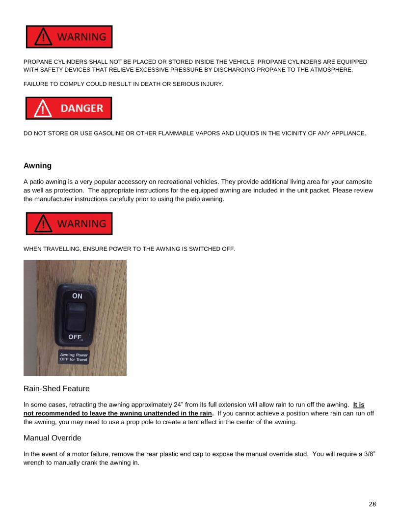
WHEN TRAVELLING, ENSURE POWER TO THE AWNING IS SWITCHED OFF.
Rain-Shed Feature
In some cases, retracting the awning approximately 24” from its full extension will allow rain to run off the awning. It is
not recommended to leave the awning unattended in the rain. If you cannot achieve a position where rain can run off
the awning, you may need to use a prop pole to create a tent effect in the center of the awning.
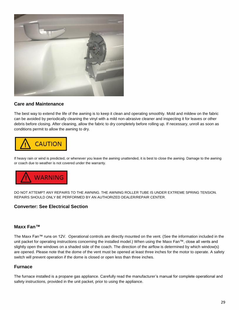
Manual Override
In the event of a motor failure, remove the rear plastic end cap to expose the manual override stud. You will require a 3/8”
wrench to manually crank the awning in.
29
Care and Maintenance
The best way to extend the life of the awning is to keep it clean and operating smoothly. Mold and mildew on the fabric
can be avoided by periodically cleaning the vinyl with a mild non-abrasive cleaner and inspecting it for leaves or other
debris before closing. After cleaning, allow the fabric to dry completely before rolling up. If necessary, unroll as soon as
conditions permit to allow the awning to dry.
If heavy rain or wind is predicted, or whenever you leave the awning unattended, it is best to close the awning. Damage to the awning
or coach due to weather is not covered under the warranty.
DO NOT ATTEMPT ANY REPAIRS TO THE AWNING. THE AWNING ROLLER TUBE IS UNDER EXTREME SPRING TENSION.
REPAIRS SHOULD ONLY BE PERFORMED BY AN AUTHORIZED DEALER/REPAIR CENTER.
Converter: See Electrical Section
Maxx Fan™
The Maxx Fan™ runs on 12V. Operational controls are directly mounted on the vent. (See the information included in the
unit packet for operating instructions concerning the installed model.) When using the Maxx Fan™, close all vents and
slightly open the windows on a shaded side of the coach. The direction of the airflow is determined by which window(s)
are opened. Please note that the dome of the vent must be opened at least three inches for the motor to operate. A safety
switch will prevent operation if the dome is closed or open less than three inches.
Furnace
The furnace installed is a propane gas appliance. Carefully read the manufacturer’s manual for complete operational and
safety instructions, provided in the unit packet, prior to using the appliance.
30
The furnace utilizes a sealed combustion system, which means the combustion chamber is completely sealed from the
inner atmosphere of your vehicle. Combustion air is drawn from the outside and combustion products are expelled outside
through a vent. The furnace is a forced-air system which pushes warm air throughout your travel trailer. The blower is
wired to operate directly from your 12-volt system.
New furnaces sometimes emit smoke and an odor during the first 5 - 10 minutes of initial use due to machine oil burning
off the heating chamber. Do not mistake this for a malfunctioning furnace. Opening windows and door prior to first lighting
will help vent any smoke or odor.
IN CASE OF TROUBLE: Consult your furnace manufacturer’s operation and service manual in your Owner’s Kit for
troubleshooting tips and information, and the location of your nearest service center.
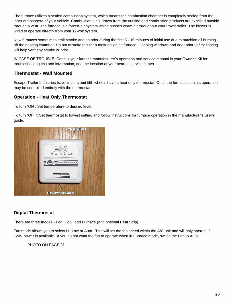
Thermostat - Wall Mounted
Escape Trailer Industries travel trailers and fifth wheels have a heat only thermostat. Once the furnace is on, its operation
may be controlled entirely with the thermostat.
Operation - Heat Only Thermostat
To turn “ON”: Set temperature to desired level.
To turn “OFF”: Set thermostat to lowest setting and follow instructions for furnace operation in the manufacturer’s user’s
guide.
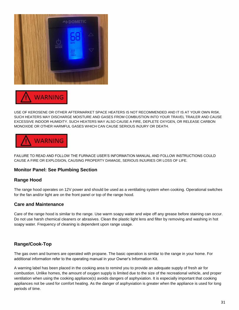
Digital Thermostat
There are three modes - Fan, Cool, and Furnace (and optional Heat Strip)
Fan mode allows you to select Hi, Low or Auto. This will set the fan speed within the A/C unit and will only operate if
120V power is available. If you do not want the fan to operate when in Furnace mode, switch the Fan to Auto.
- PHOTO ON PAGE 31.
31
USE OF KEROSENE OR OTHER AFTERMARKET SPACE HEATERS IS NOT RECOMMENDED AND IT IS AT YOUR OWN RISK.
SUCH HEATERS MAY DISCHARGE MOISTURE AND GASES FROM COMBUSTION INTO YOUR TRAVEL TRAILER AND CAUSE
EXCESSIVE INDOOR HUMIDITY. SUCH HEATERS MAY ALSO CAUSE A FIRE, DEPLETE OXYGEN, OR RELEASE CARBON
MONOXIDE OR OTHER HARMFUL GASES WHICH CAN CAUSE SERIOUS INJURY OR DEATH.
FAILURE TO READ AND FOLLOW THE FURNACE USER’S INFORMATION MANUAL AND FOLLOW INSTRUCTIONS COULD
CAUSE A FIRE OR EXPLOSION, CAUSING PROPERTY DAMAGE, SERIOUS INJURIES OR LOSS OF LIFE.
Monitor Panel: See Plumbing Section
Range Hood
The range hood operates on 12V power and should be used as a ventilating system when cooking. Operational switches
for the fan and/or light are on the front panel or top of the range hood.
Care and Maintenance
Care of the range hood is similar to the range. Use warm soapy water and wipe off any grease before staining can occur.
Do not use harsh chemical cleaners or abrasives. Clean the plastic light lens and filter by removing and washing in hot
soapy water. Frequency of cleaning is dependent upon range usage.
Range/Cook-Top
The gas oven and burners are operated with propane. The basic operation is similar to the range in your home. For
additional information refer to the operating manual in your Owner’s Information Kit.
A warning label has been placed in the cooking area to remind you to provide an adequate supply of fresh air for
combustion. Unlike homes, the amount of oxygen supply is limited due to the size of the recreational vehicle, and proper
ventilation when using the cooking appliance(s) avoids dangers of asphyxiation. It is especially important that cooking
appliances not be used for comfort heating. As the danger of asphyxiation is greater when the appliance is used for long
periods of time.
32
DO NOT OPERATE RANGE BURNERS UNLESS NEARBY PRIVACY DRAPE OR OTHER COMBUSTIBLES ARE SECURED.
FAILURE TO COMPLY COULD RESULT IN A FIRE OR SERIOUS INJURY.
Operation-Top Burners (Range or Cook-Top)
Prior to Lighting
Assure the gas supply to the trailer is turned “ON”.
Open a window and/or vent for ventilation purposes.
Check for any hazards (flammable liquids, fabrics, objects near burners).
If gas smell is present, Do Not Light. See “What to do if you smell gas” at the beginning of this chapter.
Match-Light Models:
a. All burner controls operate counter-clockwise and must be pressed inward (toward the cooktop) to turn ON or
LITE. Do not attempt to light more than one burner at a time.
b. IMMEDIATELY light the burner by holding a long lit match or a handheld spark igniter designed for this purpose
near the burner ports.
c. To extinguish the top burner flame, turn the appropriate burner knob clockwise to OFF.
Lighting Top Burners with Spark Ignition:
a. Turn the appropriate burner knob counter-clockwise to “ON” or “LITE”. Do not attempt to light more than one
burner at a time.
b. Turn the “SPARK” knob clockwise one “click”, if the burner fails to light, continue turning the “SPARK” knob
clockwise until the burner lights.
c. To extinguish the top burner flame, turn the appropriate burner knob clockwise to “OFF”.
The range or cook top installed is a propane gas appliance. Carefully read the manufacturer’s manual for complete
operational and safety instructions, provided in the unit packet, prior to using the appliance.
Operation - Oven (if equipped)
Oven pilot must be lit prior to operating.
Lighting Oven Pilot
Be sure all valves and oven control knob are in the “OFF” position.
Assure the main gas supply is on.
Open oven door and smell for gas. If odor present — Stop! Read “What to do if you smell gas”
If no gas smell present
Lighting The Oven Pilot:
a. Push in oven control knob and rotate counter-clockwise to PILOT ON.
33
b. Light oven pilot located near the back of the oven, under the broiler shelf and to the left of the oven burner.
c. Set the oven control knob to PILOT ON to maintain pilot flame. The oven and broiler are now ready for
operation. The oven pilot has been factory set and requires no further adjustment.
d. To extinguish the oven pilot, push in the oven control knob and rotate clockwise to OFF. Extinguish all pilots
when refueling or traveling.
Lighting The Oven Burner:
a. Light the oven pilot as described above.
b. With the oven control knob set to PILOT ON, push in and rotate the knob counter-clockwise to the desired
temperature setting or to BROIL. The oven will pre-heat in approximately 10 minutes. For best results, always
pre-heat the oven before use.
c. The oven is equipped with a safety ignition system that requires a minimum of 30 seconds to operate after
turning the oven control ON. This delay is normal.
d. To extinguish the oven burner, rotate the knob clockwise to PILOT ON. The oven pilot will remain lit.
e. For complete shutdown, push in and rotate the knob clockwise to OFF.
Using The Broiler:
a. Light the oven pilot as described above.
b. Push in and rotate the oven control knob counter-clockwise to BROIL.
c. Center a broiler pan under the broiler flame.
d. Move and turn the food over frequently to ensure even browning and cooking.
Care and Maintenance
Before cleaning make sure all knobs are in the “OFF” position and wait until all surfaces, including burners, are cool. Use
warm soapy water only. Do not use oven cleaners, bleach or rust removers on the range/cook top surface. Wipe up any
spills as soon as possible to avoid possible discoloration or pitting on the surface. Check burner ports when cleaning. If
the ports or the orifice are clogged, carefully clean with a toothpick.
IT IS NOT SAFE TO USE COOKING APPLIANCES FOR COMFORT HEATING. COOKING APPLIANCES NEED FRESH AIR FOR
SAFE OPERATION.
BEFORE OPERATION:
(1) OPEN OVERHEAD VENT OR TURN ON EXHAUST FAN
(2) OPEN WINDOW
FAILURE TO COMPLY COULD RESULT IN DEATH OR SERIOUS INJURY.
UNLIKE HOMES, THE AMOUNT OF OXYGEN SUPPLY IS LIMITED DUE TO THE SIZE OF THE RECREATIONAL VEHICLE, AND
PROPER VENTILATION WHEN USING THE COOKING APPLIANCE(S) AVOIDS DANGERS OF ASPHYXIATION. IT IS
34
ESPECIALLY IMPORTANT THAT COOKING APPLIANCES NOT BE USED FOR COMFORT HEATING, AS THE DANGER OF
ASPHYXIATION IS GREATER WHEN THE APPLIANCE IS USED FOR LONG PERIODS OF TIME.
FAILURE TO COMPLY COULD RESULT IN DEATH OR SERIOUS INJURY.
IF YOU SMELL PROPANE
(1) EXTINGUISH ANY OPEN FLAMES, PILOT LIGHTS, AND ALL SMOKING MATERIALS
(2) DO NOT TOUCH ELECTRICAL SWITCHES
(3) SHUT OFF THE PROPANE SUPPLY CONTAINER VALVE(S) OR PROPANE SUPPLY CONNECTION
(4) OPEN DOORS AND OTHER VENTILATING OPENINGS
(5) LEAVE THE AREA UNTIL ODOR CLEARS
(6) HAVE THE PROPANE SYSTEM CHECKED AND LEAKAGE SOURCE CORRECTED BEFORE USING AGAIN
FAILURE TO COMPLY COULD RESULT IN EXPLO¬SION RESULTING IN DEATH OR SERIOUS INJURY.
BURN INJURY, FIRE AND/OR EXPLOSION
• USE RANGE OR COOKTOP ONLY FOR USE AS DESCRIBED IN THIS MANUAL.
• DO NOT LEAVE CHILDREN ALONE OR UNATTENDED IN AREA WHERE RANGE OR COOKTOP IS IN USE. NEVER ALLOW
ANYONE TO SIT, STAND, OR CLIMB ON ANY PART OF THE RANGE COOKTOP. THEY COULD BE BURNED OR INJURED.
• DO NOT STORE THINGS CHILDREN MIGHT WANT ABOVE THE RANGE OR COOKTOP. CHILDREN COULD BE BURNED OR
INJURED WHILE CLIMBING ON IT.
• DO NOT WEAR LOOSE OR HANGING GARMENTS WHEN USING THE RANGE OR COOKTOP. THEY COULD IGNITE IF THEY
TOUCH AN OPEN FLAME AND YOU COULD BE BURNED.
• USE ONLY DRY POTHOLDERS. MOIST OR DAMP POTHOLDERS ON HOT SURFACES MAY RESULT IN BURNS FROM STEAM.
DO NOT LET THE POTHOLDER TOUCH AN OPEN FLAME. DO NOT USE A TOWEL OR BULKY CLOTH FOR A POTHOLDER. IT
COULD CATCH ON FIRE.
• DO NOT HEAT UNOPENED CONTAINERS. THEY COULD EXPLODE. THE HOT CONTENTS MAY CAUSE BURNS AND
CONTAINER PARTICLES MAY CAUSE INJURY.
• DO NOT STORE FLAMMABLE MATERIALS ON, IN, OR NEAR THE RANGE OR COOKTOP. ANY FUMES CAN CREATE AN
EXPLOSION AND/ OR FIRE HAZARD.
NEVER USE WIRE BRUSHES OR ANY METALLIC ITEM FOR CLEANING RANGE PORTS OR ORIFICE, AS WIRE BRUSHES OR
METALLIC ITEMS MAY SHED, LEADING TO A FIRE OR EXPLOSION.
35
BURN INJURY, FIRE AND/OR EXPLOSION
• DO NOT OPERATE RANGE OR COOKTOP IF IT IS DAMAGED OR NOT WORKING PROPERLY.
• KNOW WHERE YOUR VEHICLE’S MAIN PROPANE GAS SHUTOFF IS LOCATED.
• VERIFY SUFFICIENT GAS SUPPLY BEFORE ATTEMPTING TO LIGHT ANY TOP BURNER. AIR IN THE GAS SUPPLY LINE WILL
SIGNIFICANTLY DELAY BURNER IGNITION, AND A BURNER MAY LIGHT UNEXPECTEDLY AS THE AIR IN THE LINE CLEARS
OUT AND IS REPLACED BY PROPANE GAS; THIS UNEXPECTED IGNITION MAY BURN YOU. AIR MAY BE INTRODUCED INTO
THE SUPPLY LINE WHEN THE VEHICLE GAS BOTTLE IS REPLACED, DURING SERVICING OF OTHER GAS APPLIANCES, ETC.
• IF ANY BURNER SHOULD EXTINGUISH (AFTER INITIALLY LIGHTING OR DUE TO ACCIDENTAL BLOW-OUT), TURN ALL
BURNER KNOBS CLOCKWISE TO OFF AND WAIT FIVE (5) MINUTES BEFORE AGAIN ATTEMPTING TO LIGHT THE BURNER.
(WARNING Continued)
• DO NOT TOUCH TOP BURNERS, BURNER GRATES, OR OTHER AREAS NEAR TOP BURNERS DURING AND AFTER USE. DO
NOT LET CLOTHING OR OTHER FLAMMABLE MATERIALS TO CONTACT TOP BURNERS OR AREAS NEAR TOP BURNERS
UNTIL THEY HAVE HAD SUFFICIENT TIME TO COOL
• MAKE SURE THE UTENSILS YOU USE ARE LARGE ENOUGH TO CONTAIN FOOD AND AVOID BOIL OVERS AND
SPILLOVERS. HEAVY SPLATTERING OR SPILLOVERS LEFT ON THE COOKTOP CAN IGNITE AND BURN YOU.
• BE SURE THAT GLASS COOKING UTENSILS ARE SAFE FOR USE ON THE COOKTOP. ONLY CERTAIN KINDS OF GLASS
UTENSILS ARE SUITABLE FOR SURFACE OR TOP BURNER USE WITHOUT BREAKING DUE TO THE SUDDEN CHANGES IN
TEMPERATURE.
• NEVER LEAVE TOP BURNERS UNATTENDED. A BOIL OVER COULD RESULT AND CAUSE SMOKING AND GREASY
SPILLOVERS THAT MAY IGNITE.
• TURN PAN HANDLES INWARD, BUT NOT OVER OTHER TOP BURNERS. THIS REDUCES THE CHANCE OF BURNS DUE TO
BUMPING PAN.
• GREASE IS FLAMMABLE. NEVER ALLOW GREASE TO COLLECT AROUND TOP BURNERS OR ON COOKTOP SURFACE.
WIPE SPILLOVERS IMMEDIATELY.
• DO NOT USE WATER ON GREASE FIRES. NEVER PICK UP A FLAMING PAN. SMOTHER A FLAMING PAN WITH A TIGHT-
FITTING LID OR COOKIE SHEET. FLAMING GREASE OUTSIDE OF THE PAN CAN BE EXTINGUISHED WITH BAKING SODA OR
A MULTIPURPOSE DRY CHEMICAL OR FOAM-TYPE FIRE EXTINGUISHER.
• USE CARE WHEN LIGHTING A TOP BURNER BY HAND. IF THE BURNER LIGHTS UNEXPECTEDLY, OR YOUR HAND IS
CLOSE TO THE BURNER, YOU MAY BE BURNED.
• BURNER FLAME SHOULD NOT EXTEND BEYOND THE EDGE OF THE COOKING UTENSIL. THE FLAME COULD BURN YOU
AND CAUSE POOR COOKING RESULTS.
• BE SURE ALL CONTROL KNOBS ARE TURNED TO OFF WHEN YOU ARE NOT COOKING. SOMEONE COULD BE BURNED OR
A FIRE COULD START IF A BURNER IS ACCIDENTALLY LEFT ON .
ALL PILOT LIGHTS, APPLIANCES, AND THEIR IGNITORS (SEE OPERATING INSTRUCTIONS) SHALL BE TURNED OFF BEFORE
REFUELING OF MOTOR FUEL TANKS AND/OR PROPANE CONTAINERS. FAILURE TO COMPLY COULD RESULT IN DEATH OR
SERIOUS INJURY.
36
MOST PROPANE GAS APPLIANCES ARE VENTED TO THE OUTSIDE. GASOLINE FUMES COULD ENTER THE APPLIANCE AND
IGNITE FROM THE BURNER FLAME, CAUSING AN EXPLOSION OR FIRE
RV Refrigerator
The refrigerator installed is a propane gas appliance. Carefully read the manufacturer’s manual for complete operational
and safety instructions, provided in the unit packet, prior to using the appliance.
Operation
The refrigerator operates on either 120V, 12V,or propane gas and has a gravity-based cooling system. This system
requires that the recreational vehicle be level for efficient operation. The cooling coils are sloped to allow continuous
movement of the liquid chemicals. If the unit is not level for extended periods, the flow of these chemicals will slow and
pool inside the tubing, resulting in a loss of cooling.
During towing, the leveling is not as crucial as the movement of the trailer will prevent the liquid inside the tubing from
pooling. If needing to park for several hours, the trailer should be leveled if operating the refrigerator, or the refrigerator
needs to be turned off.
When starting the refrigerator for the first time or after extended storage, allow up to four hours for the cooling cycle to
become fully operational.
Operational Controls
Auto Mode:
The control system on the refrigerator will automatically select between gas and AC electric operation. AC will always be
selected if available. If AC becomes unavailable, the refrigerator will switch to gas mode operation. When in auto mode
the indicator lamp on the control panel will be lit.
Propane Gas Mode:
This mode when selected provides gas operation only. If the propane burner does not ignite within three attempts, the
‘Check’ light will come on indicating the fridge is not operating. Refer to the fridge manual for troubleshooting tips.
12V Mode:
12V mode should only be used while travelling. Ensure your vehicle is charging the battery when the 7-pin is connected.
As the fridge will draw 10-13 amps (depending on the fridge size) it can drain a battery in approx. 1.5 hrs.
Care and Maintenance
Exterior: Ventilation of the refrigerator is essential. Make sure the vents are clear of any obstructions such as bird/insect
nests, spider webs, or any other debris. Periodically clean the coils on the back of the refrigerator with a soft bristled
brush. At no time should any combustible materials, such as gasoline, flammable liquids or vapors be stored near the
refrigerator.
Interior: When cleaning the interior lining of the refrigerator, use a weak solution of baking soda and warm water. Use
only warm water, however, when cleaning the finned evaporator, ice trays and shelves. Never use harsh chemicals or
abrasive cleaners to clean these parts or their protective coatings will be damaged.
Defrosting: When defrosting the refrigerator, shut off the power by turning the main power button to the off position.
Remove any food and leave the drip tray under the finned evaporator. Leave the door(s) open and empty drip pan when
necessary. Dry with a soft cloth when done.
ANY SERVICE TO THE REFRIGERATOR MUST BE PERFORMED BY A QUALIFIED REPAIR TECHNICIAN.
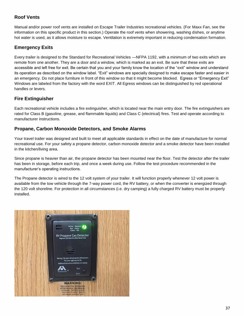
37
Roof Vents
Manual and/or power roof vents are installed on Escape Trailer Industries recreational vehicles. (For Maxx Fan, see the
information on this specific product in this section.) Operate the roof vents when showering, washing dishes, or anytime
hot water is used, as it allows moisture to escape. Ventilation is extremely important in reducing condensation formation.
Emergency Exits
Every trailer is designed to the Standard for Recreational Vehicles —NFPA 1192, with a minimum of two exits which are
remote from one another. They are a door and a window, which is marked as an exit. Be sure that these exits are
accessible and left free for exit. Be certain that you and your family know the location of the “exit” window and understand
its operation as described on the window label. “Exit” windows are specially designed to make escape faster and easier in
an emergency. Do not place furniture in front of this window so that it might become blocked. Egress or “Emergency Exit”
Windows are labeled from the factory with the word EXIT. All Egress windows can be distinguished by red operational
handles or levers.
Fire Extinguisher
Each recreational vehicle includes a fire extinguisher, which is located near the main entry door. The fire extinguishers are
rated for Class B (gasoline, grease, and flammable liquids) and Class C (electrical) fires. Test and operate according to
manufacturer instructions.
Propane, Carbon Monoxide Detectors, and Smoke Alarms
Your travel trailer was designed and built to meet all applicable standards in effect on the date of manufacture for normal
recreational use. For your safety a propane detector, carbon monoxide detector and a smoke detector have been installed
in the kitchen/living area.
Since propane is heavier than air, the propane detector has been mounted near the floor. Test the detector after the trailer
has been in storage, before each trip, and once a week during use. Follow the test procedure recommended in the
manufacturer’s operating instructions.
The Propane detector is wired to the 12 volt system of your trailer. It will function properly whenever 12 volt power is
available from the tow vehicle through the 7-way power cord, the RV battery, or when the converter is energized through
the 120 volt shoreline. For protection in all circumstances (i.e. dry camping) a fully charged RV battery must be properly
installed.
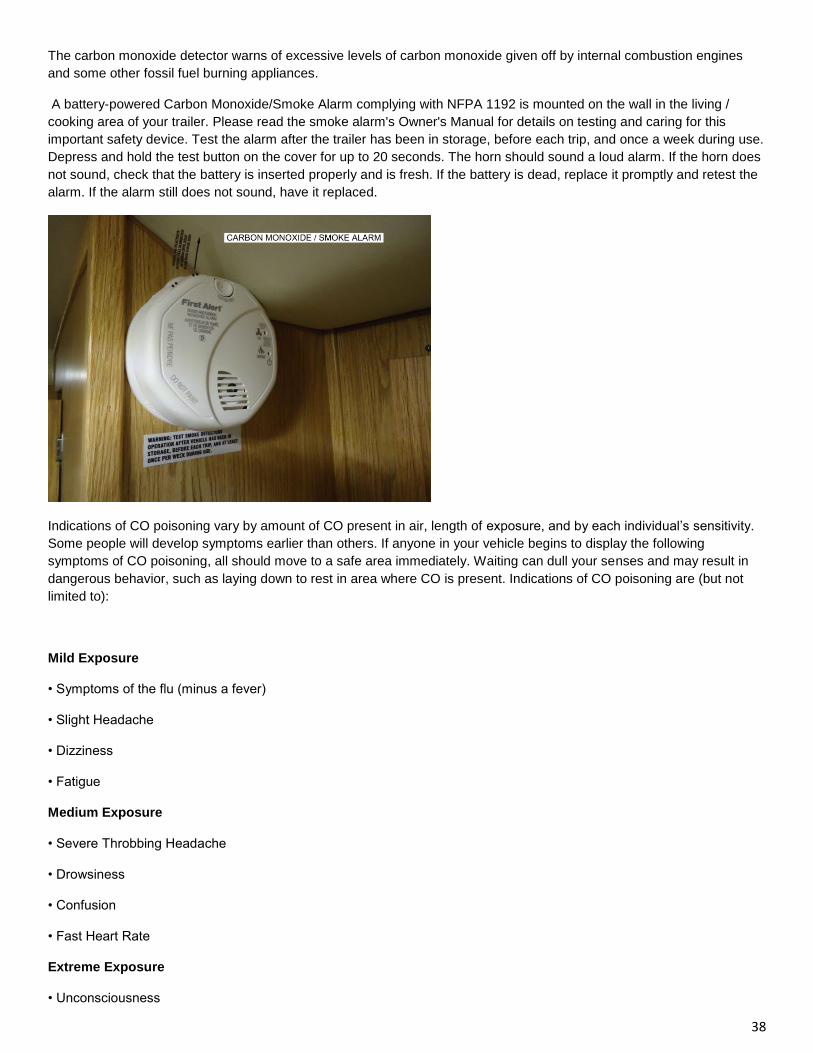
38
The carbon monoxide detector warns of excessive levels of carbon monoxide given off by internal combustion engines
and some other fossil fuel burning appliances.
A battery-powered Carbon Monoxide/Smoke Alarm complying with NFPA 1192 is mounted on the wall in the living /
cooking area of your trailer. Please read the smoke alarm's Owner's Manual for details on testing and caring for this
important safety device. Test the alarm after the trailer has been in storage, before each trip, and once a week during use.
Depress and hold the test button on the cover for up to 20 seconds. The horn should sound a loud alarm. If the horn does
not sound, check that the battery is inserted properly and is fresh. If the battery is dead, replace it promptly and retest the
alarm. If the alarm still does not sound, have it replaced.
Indications of CO poisoning vary by amount of CO present in air, length of exposure, and by each individual’s sensitivity.
Some people will develop symptoms earlier than others. If anyone in your vehicle begins to display the following
symptoms of CO poisoning, all should move to a safe area immediately. Waiting can dull your senses and may result in
dangerous behavior, such as laying down to rest in area where CO is present. Indications of CO poisoning are (but not
limited to):
Mild Exposure
• Symptoms of the flu (minus a fever)
• Slight Headache
• Dizziness
• Fatigue
Medium Exposure
• Severe Throbbing Headache
• Drowsiness
• Confusion
• Fast Heart Rate
Extreme Exposure
• Unconsciousness
39
• Convulsions
• Cardiorespiratory Failure
• Death
For your safety and to keep your carbon monoxide alarm in good working order, follow the steps below.
• Verify the unit alarm, lights and battery operation by pushing the “Test” button weekly.
• Vacuum the CO alarm cover with a soft brush attachment once a month to remove accumulated dust.
• Instruct children never to play with the CO alarm. Warn children of the dangers of carbon monoxide poisoning.
• Never use detergents or solvents to clean the carbon monoxide alarm.
• Avoid spraying paint, hair spray, air fresheners or other aerosols near the CO detector.
• Do Not paint the CO detector. Paint will seal the vents and interfere with the sensor ability to detect CO.
• Test the alarm operation after your trailer has been in storage, before each trip and at least once a week during the
camping season.
ACTUATION OF YOUR CO ALARM INDICATES THE PRESENCE OF CARBON MONOXIDE (CO) WHICH CAN KILL YOU. IF THE
ALARM SOUNDS; 1) OPERATE THE RESET/SILENCE BUTTON; 2) CALL YOUR EMERGENCY SERVICES (PHONE NUMBER
__________________) (FIRE DEPARTMENT OR 911); 3) IMMEDIATELY MOVE TO FRESH AIR - OUTDOORS OR BY AN OPEN
DOOR/WINDOW. DO A HEAD COUNT TO CHECK THAT ALL PERSONS ARE ACCOUNTED FOR . DO NOT RE-ENTER THE
PREMISES NOR MOVE AWAY FROM THE OPEN DOOR/WINDOW UNTIL THE EMERGENCY RESPONDERS HAVE ARRIVED,
THE PREMISES HAVE BEEN AIRED OUT, AND YOUR ALARM REMAINS IN ITS NORMAL OPERATION. 4) AFTER FOLLOWING
STEPS 1-3, IF YOUR ALARM REACTIVATES WITHIN A 24 HOUR PERIOD, REPEAT STEPS 1-3 AND CALL A QUALIFIED
APPLIANCE TECHNICIAN. (PHONE NUMBER _________________) TO INVESTIGATE FOR SOURCES OF CO FROM FUEL
BURNING EQUIPMENT AND APPLIANCES, AND INSPECT FOR PROPER OPERATION OF THIS EQUIPMENT. IF PROBLEMS
ARE IDENTIFIED DURING THIS INSPECTION HAVE THE EQUIPMENT SERVICED IMMEDIATELY. NOTE ANY COMBUSTION
EQUIPMENT NOT INSPECTED BY THE TECHNICIAN AND CONSULT THE MANUFACTURERS' INSTRUCTIONS, OR CONTACT
THE MANUFACTURER DIRECTLY, FOR MORE INFORMATION ABOUT CO SAFETY AND THIS EQUIPMENT
IF THE ALARM SOUNDS, PROVIDE VENTILATION BY OPENING WINDOWS AND DOORS. THE CO BUILD-UP MAY DISSIPATE
BEFORE HELP ARRIVES, BUT MAY BE ONLY TEMPORARILY SOLVED. IT IS CRUCIAL THAT THE SOURCE OF THE CO IS
DETERMINED AND REPAIRED.
THE CO ALARM CAN ONLY WARN YOU IN THE PRESENCE OF CO. IT DOES NOT PREVENT CO FROM OCCURRING NOR CAN
IT SOLVE AN EXISTING CO PROBLEM.

40
CARBON MONOXIDE CAN BE FATAL! WHEN THE DEVICE DETECTS CARBON MONOXIDE IN THE AIR IT WILL SOUND.
CONSULT THE INDIVIDUAL DETECTOR’S USER MANUAL FOR SPECIFIC INSTRUCTIONS AND/OR AUDIBLE WARNING
MEANINGS.
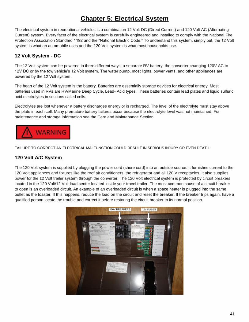
41
Chapter 5: Electrical System
The electrical system in recreational vehicles is a combination 12 Volt DC (Direct Current) and 120 Volt AC (Alternating
Current) system. Every facet of the electrical system is carefully engineered and installed to comply with the National Fire
Protection Association Standard 1192 and the “National Electric Code.” To understand this system, simply put, the 12 Volt
system is what an automobile uses and the 120 Volt system is what most households use.
12 Volt System - DC
The 12 Volt system can be powered in three different ways: a separate RV battery, the converter changing 120V AC to
12V DC or by the tow vehicle’s 12 Volt system. The water pump, most lights, power vents, and other appliances are
powered by the 12 Volt system.
The heart of the 12 Volt system is the battery. Batteries are essentially storage devices for electrical energy. Most
batteries used in RVs are RV/Marine Deep Cycle, Lead- Acid types. These batteries contain lead plates and liquid sulfuric
acid electrolytes in sections called cells.
Electrolytes are lost whenever a battery discharges energy or is recharged. The level of the electrolyte must stay above
the plate in each cell. Many premature battery failures occur because the electrolyte level was not maintained. For
maintenance and storage information see the Care and Maintenance Section.
FAILURE TO CORRECT AN ELECTRICAL MALFUNCTION COULD RESULT IN SERIOUS INJURY OR EVEN DEATH.
120 Volt A/C System
The 120 Volt system is supplied by plugging the power cord (shore cord) into an outside source. It furnishes current to the
120 Volt appliances and fixtures like the roof air conditioners, the refrigerator and all 120 V receptacles. It also supplies
power for the 12 Volt trailer system through the converter. The 120 Volt electrical system is protected by circuit breakers
located in the 120 Volt/12 Volt load center located inside your travel trailer. The most common cause of a circuit breaker
to open is an overloaded circuit. An example of an overloaded circuit is when a space heater is plugged into the same
outlet as the toaster. If this happens, reduce the load on the circuit and reset the breaker. If the breaker trips again, have a
qualified person locate the trouble and correct it before restoring the circuit breaker to its normal position.
42
Power Cord/Shore Cord
The power cord, often referred to as shore cord or shoreline, is a heavy-duty cable with a 3 prong grounding plug on one
end and connects directly to the power converter inside the unit on the other end. This cord is used to plug into an
external 120V source. Cords are 30 Amp plugs (3 prong. This cord is designed to ground the electrical system.
30 Amp Available Power
30 Amp service is 120 Volt service limited to a total draw of 30 amps. The power cord from the RV is three pronged. 30
Amp service is the most common in the RV industry and used widely in campgrounds through Canada and the United
States. With 30 Amp service any appliance in the RV can operate by itself.
The power cord prongs should always be clean and solid. Clean with a contact cleaner, emery cloth and or a nail file. Electrical
connections work better when clean.
NEVER REPLACE CIRCUIT BREAKERS OR FUSES OF HIGHER CURRENT RATING THAN THOSE ORIGINALLY INSTALLED.
THIS COULD OVERHEAT THE WIRING AND START A FIRE.
Converter
Your travel trailer is equipped with a load center. The load center has a built-in converter that automatically converts 120-
volt current to 12-volt current for use by those circuits which require it and also recharges your battery. No switching is
necessary. If an exterior source of power is connected, the converter automatically switches to this source rather than the
trailer battery. If the converter is not connected to a 120-volt power source your 12-volt system will draw power from the
battery.
Whenever city power (120V) is available it should be used to avoid discharging the trailer battery. When the power cord
between the travel trailer and the tow vehicle is connected, the trailer and tow vehicle electrical systems operate as one.
The trailer battery is recharged by the tow vehicle’s alternator and when parked, the tow vehicle battery can be discharged
by prolonged power usage in the trailer. Consequently, when parked and operating from the trailer batteries, the cord
between the tow vehicle and travel trailer should be disconnected to avoid running down your tow vehicle battery. The
trailer battery can be recharged by starting the tow vehicle and reconnecting the power cord. When operating off batteries
it is wise to use lights and power sparingly.
GFCI — (Ground Fault Circuit Interrupter)
Protection against ground fault is provided on kitchen, and outside receptacle circuits with a special GFCI receptacle, or
by a GFI circuit breaker. These devices are designed to break the circuit when it detects an imbalance in the current flow.
The imbalance can be due to an appliance failure which could result in serious injury or death to the user.
Familiarize yourself with the operation and testing of the GFCI. It is an important device which could save your life. If the
GFCI breaks the circuit, be sure to have the appliance you were using serviced prior to using it again.
Even with the protection of a GFCI, electrical shock may be felt but will usually be of less than normally dangerous
duration, except for persons with heart problems or other conditions that may make them particularly susceptible to
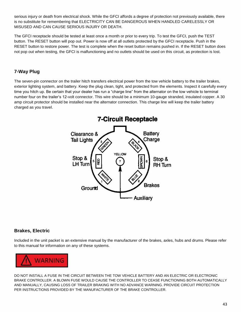
43
serious injury or death from electrical shock. While the GFCI affords a degree of protection not previously available, there
is no substitute for remembering that ELECTRICITY CAN BE DANGEROUS WHEN HANDLED CARELESSLY OR
MISUSED AND CAN CAUSE SERIOUS INJURY OR DEATH.
The GFCI receptacle should be tested at least once a month or prior to every trip. To test the GFCI, push the TEST
button. The RESET button will pop out. Power is now off at all outlets protected by the GFCI receptacle. Push in the
RESET button to restore power. The test is complete when the reset button remains pushed in. If the RESET button does
not pop out when testing, the GFCI is malfunctioning and no outlets should be used on this circuit, as protection is lost.
7-Way Plug
The seven-pin connector on the trailer hitch transfers electrical power from the tow vehicle battery to the trailer brakes,
exterior lighting system, and battery. Keep the plug clean, tight, and protected from the elements. Inspect it carefully every
time you hitch up. Be certain that your dealer has run a “charge line” from the alternator on the tow vehicle to terminal
number four on the trailer’s 12-volt connector. This wire should be a minimum 10-gauge stranded, insulated copper. A 30
amp circuit protector should be installed near the alternator connection. This charge line will keep the trailer battery
charged as you travel.
Brakes, Electric
Included in the unit packet is an extensive manual by the manufacturer of the brakes, axles, hubs and drums. Please refer
to this manual for information on any of these systems.
DO NOT INSTALL A FUSE IN THE CIRCUIT BETWEEN THE TOW VEHICLE BATTERY AND AN ELECTRIC OR ELECTRONIC
BRAKE CONTROLLER. A BLOWN FUSE WOULD CAUSE THE CONTROLLER TO CEASE FUNCTIONING BOTH AUTOMATICALLY
AND MANUALLY, CAUSING LOSS OF TRAILER BRAKING WITH NO ADVANCE WARNING. PROVIDE CIRCUIT PROTECTION
PER INSTRUCTIONS PROVIDED BY THE MANUFACTURER OF THE BRAKE CONTROLLER.
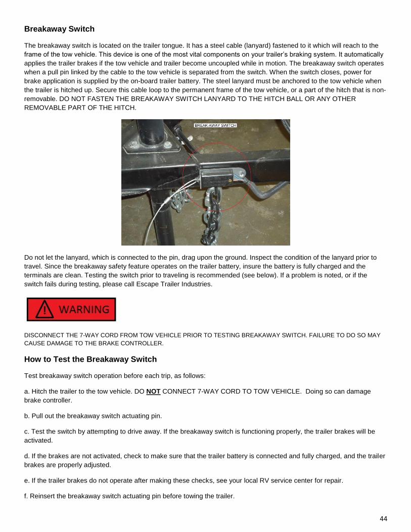
44
Breakaway Switch
The breakaway switch is located on the trailer tongue. It has a steel cable (lanyard) fastened to it which will reach to the
frame of the tow vehicle. This device is one of the most vital components on your trailer’s braking system. It automatically
applies the trailer brakes if the tow vehicle and trailer become uncoupled while in motion. The breakaway switch operates
when a pull pin linked by the cable to the tow vehicle is separated from the switch. When the switch closes, power for
brake application is supplied by the on-board trailer battery. The steel lanyard must be anchored to the tow vehicle when
the trailer is hitched up. Secure this cable loop to the permanent frame of the tow vehicle, or a part of the hitch that is non-
removable. DO NOT FASTEN THE BREAKAWAY SWITCH LANYARD TO THE HITCH BALL OR ANY OTHER
REMOVABLE PART OF THE HITCH.
Do not let the lanyard, which is connected to the pin, drag upon the ground. Inspect the condition of the lanyard prior to
travel. Since the breakaway safety feature operates on the trailer battery, insure the battery is fully charged and the
terminals are clean. Testing the switch prior to traveling is recommended (see below). If a problem is noted, or if the
switch fails during testing, please call Escape Trailer Industries.
DISCONNECT THE 7-WAY CORD FROM TOW VEHICLE PRIOR TO TESTING BREAKAWAY SWITCH. FAILURE TO DO SO MAY
CAUSE DAMAGE TO THE BRAKE CONTROLLER.
How to Test the Breakaway Switch
Test breakaway switch operation before each trip, as follows:
a. Hitch the trailer to the tow vehicle. DO NOT CONNECT 7-WAY CORD TO TOW VEHICLE. Doing so can damage
brake controller.
b. Pull out the breakaway switch actuating pin.
c. Test the switch by attempting to drive away. If the breakaway switch is functioning properly, the trailer brakes will be
activated.
d. If the brakes are not activated, check to make sure that the trailer battery is connected and fully charged, and the trailer
brakes are properly adjusted.
e. If the trailer brakes do not operate after making these checks, see your local RV service center for repair.
f. Reinsert the breakaway switch actuating pin before towing the trailer.
45
THE BREAKAWAY SWITCH IS FOR EMERGENCY USE ONLY.
DO NOT TOW A TRAILER WITH A MALFUNCTIONING BREAKAWAY SWITCH. DO NOT LEAVE THE PULL PIN OUT OF THE
BREAKAWAY SWITCH FOR MORE THAN A FEW MINUTES, OR THE BATTERY WILL BE DRAINED. DO NOT USE THE
BREAKAWAY SWITCH FOR A PARKING BRAKE.
The Braking System
The electric brakes on your trailer are operated by 12-Volt current from the tow vehicle. The brakes have been factory-
calibrated for smooth, positive response. During the break-in period, brakes may squeak. This is normal, and will cease
after a few kilometers.
Brake System Components
Tow Vehicle Battery. This is the primary power source for the trailer braking system. The connection is made at the
positive post of the battery, or at the tow vehicle starter solenoid battery terminal.
Brake Controller. The electric trailer brakes are automatically applied by the brake controller, which is usually mounted
within easy reach of the tow vehicle driver. Most experienced drivers prefer to have the trailer brakes set to engage
slightly before those of the tow vehicle.
This is particularly helpful during rainy weather or slippery conditions. If the tow vehicle brakes first, the trailer will have a
tendency to push the tow vehicle or possibly “jackknife.” Lag time can be adjusted by turning the brake controller knob
according to the instructions provided with the controller. The new setting will be retained until a new adjustment is made.
Brake controllers usually have a manual feature, which allows you to apply the trailer brakes independently of the tow
vehicle brakes. Connect the controller to the brakes with 12-gauge stranded wire.
46
Chapter 6: Propane Gas System
Read all manufacturer appliance literature, including the information on the propane bottles and regulator, provided within
the unit packet and follow any instructions given.
General Information
Propane gas (also called LP, LPG or Liquefied Petroleum) when properly handled, is a clean burning dependable fuel for
operating all propane gas appliances. The propane gas system involves the tank(s) (also called bottles or cylinders),
regulators, valves, supply lines and appliances. Propane tanks contain liquid under high pressure, which vaporizes into a
gas and passes through the regulator to automatically reduce the pressure. Low-pressure gas is then distributed through
the supply lines to provide the fuel for propane appliances.
Consumption of propane gas depends upon the frequency and duration of use of the propane appliances. The
refrigerator, range/oven, water heater and furnace all operate on propane. The furnace and oven have the highest
consumption rates. During cold weather it is advisable to check the bottles often and always keep one full. Safety must be
observed at all times when using the propane gas system. Propane gas is colorless and odorless in its natural state. A
strong odorant, similar to rotten egg smell, has been added for consumer safety purposes to help detect leaks and provide
warning.
Propane burns readily and yields a great deal of energy. Under proper conditions and careful handling, it is safe,
economical, and ideally suited for use where conventional fuels are not easily utilized.
Propane Regulator
The regulator is the heart of the propane system. Propane gas is under high pressure in the bottle and the regulator
reduces this pressure to less than one pound per square inch, to allow safe use with the appliances in recreational
vehicles.
The lower pressure is distributed to the appliances. The arrow on the automatic gas regulator will always point to the gas
bottle in service. When the red flag appears in the inspection glass, this indicates that bottle is empty.
Care and Maintenance
The regulator has a vent that allows it to breathe. If pressure builds too high within the regulator, it vents until pressure
reaches a normal range. Check the vent frequently to keep the vent clean and clear of any debris, corrosion or
obstruction. A clogged regulator can result in higher pressures, loss of fuel and/or component failure. The vent can be
cleaned by using a toothbrush and should be checked periodically by a qualified propane service center.
THIS PROPANE PIPING SYSTEM IS DESIGNED FOR USE WITH PROPANE ONLY. DO NOT CONNECT NATURAL GAS TO THIS
SYSTEM.
47
PROPANE IS HIGHLY FLAMMABLE AND DANGEROUS. It is not poisonous, BUT WILL INDUCE DROWSINESS AND MAY CAUSE
SUFFOCATION. Under ordinary circumstances, breathing small amounts should not be harmful. Use extreme caution — and see that
others do — when filling the storage tank(s). There should be no flame or spark or anything which might induce a spark within at least
25 feet of the filling operation.
IF YOU SMELL PROPANE:
1. EXTINGUISH ANY OPEN FLAMES, PILOT LIGHTS, AND ALL SMOKING MATERIALS.
2. DO NOT TOUCH ELECTRICAL SWITCHES.
3. SHUT OFF THE PROPANE CONTAINER VALVE(S) OR PROPANE SUPPLY CONNECTION.
4. OPEN DOORS AND OTHER VENTILATING OPENINGS.
5. LEAVE THE AREA UNTIL ODOR CLEARS.
6. HAVE THE PROPANE SYSTEM CHECKED AND LEAKAGE SOURCE CORRECTED BEFORE USING AGAIN.
FAILURE TO COMPLY COULD RESULT IN EXPLOSION RESULTING IN SERIOUS INJURY OR DEATH.
PROPANE REGULATORS MUST ALWAYS BE INSTALLED WITH THE DIAPHRAGM VENT FACING DOWNWARD. REGULATORS
THAT ARE NOT IN COMPARTMENTS HAVE BEEN EQUIPPED WITH A PROTECTIVE COVER. MAKE SURE THAT THE
REGULATOR VENT FACES DOWNWARD AND THAT THE COVER IS KEPT IN PLACE TO MINIMIZE VENT BLOCKAGE WHICH
COULD RESULT IN EXCESSIVE PROPANE PRESSURE CAUSING FIRE OR EXPLOSION THAT COULD CAUSE SERIOUS
INJURY OR DEATH.
DO NOT ATTEMPT TO ADJUST OR REPAIR REGULATOR. ADJUSTMENTS AND REPAIRS REQUIRE SPECIALIZED TRAINING
AND TOOLS. CONTACT A QUALIFIED PROPANE SERVICE TECHNICIAN. FAILURE TO FOLLOW THESE INSTRUCTIONS
COULD RESULT IN A FIRE, EXPLOSION AND/OR INJURIES, INCLUDING LOSS OF LIFE.
Filling Propane Gas Bottles
Propane systems are equipped with a Type 1 cylinder connection, making them as easy to connect and disconnect as a
garden hose.
The Type 1 connection system uses the Excess Flow Pigtail Hose, distinguished by the large green nylon swivel nut. The
green swivel nut attaches to the outside of the cylinder valve with right hand threads. Tighten the swivel nut by hand. DO
NOT use tools.
The safety features of this system prevent gas from flowing unless the connection is tight and will limit excessive gas flow.
In cases of extreme heat, 240º to 300ºF, at the connection, the connection to the cylinder will be shut down.
48
DO NOT FILL CONTAINER(S) TO MORE THAN 80 PERCENT OF CAPACITY. FAILURE TO COMPLY COULD RESULT IN A DEATH
OR SERIOUS INJURY.
OVERFILLING THE PROPANE CONTAINER CAN RESULT IN UNCONTROLLED PROPANE FLOW, WHICH CAN CAUSE FIRE OR
EXPLOSION. A PROPERLY FILLED CONTAINER CONTAINS APPROXIMATELY 80 PERCENT OF ITS VOLUME AS LIQUID
PROPANE.
PROPANE CYLINDERS SHALL NOT BE PLACED OR STORED INSIDE THE VEHICLE. PROPANE CYLINDERS ARE EQUIPPED
WITH SAFETY DEVICES THAT RELIEVE EXCESSIVE PRESSURE BY DISCHARGING PROPANE TO THE ATMOSPHERE.
FAILURE TO COMPLY COULD RESULT IN DEATH OR SERIOUS INJURY.
Propane Gas Lines
Although your propane gas system was thoroughly inspected for leaks before delivery, gas fittings can loosen from
vibration during travel. The propane gas system should be inspected at least once a year.
Bleeding Air From Propane Lines
If the tank is completely emptied, it is possible that air has gotten into the gas lines. If this happens, you will probably find
it difficult to light the pilots on the appliances. Air can be forced from the lines by lighting the appliance closest to the
propane cylinders, and then the next closest, etc. This will cause the propane pressure to force the air out of the lines
completely. You will find that pilots will not light as readily when air is escaping through them — be patient and they will
light.
Propane Gas Leak Detector
Read the operating instructions, located in the unit packet thoroughly for the specific model installed in the unit.
The propane gas leak detector is a safety device that is permanently mounted near the floor and is powered by 12V (the
RV battery and/ or converter). The detector is operational only as long as sufficient battery power is available. If the power
is disconnected, the monitor will not operate.
Should a propane leak occur, the detector will sound an alarm and continue until the gas has dissipated or until a mute
button is pressed. The button will only stop the alarm from sounding for 60 seconds and will recur if gas is still present.
The alarm may sound at times when no propane is present due to household product use such as aerosol hair spray,
cleaners, adhesives, alcohol etc. Be sure to air out the trailer thoroughly when using these products and never allow them
to spray directly on the detector.
The propane gas leak detector has a self-check circuit which runs at all times while receiving 12 Volt power. In the event
that the circuitry fails, a failure alarm will sound and the operating indicator will cease to light.
When To Test Detector
Testing of the detector is recommended every week, if power is interrupted or before each camping trip. The propane
detector must be operating for at least 60 seconds before it can be tested.
49
Chapter 7: Plumbing System
A recreational vehicle plumbing system consists of two sub-systems: The fresh water system and the waste water system.
Water System
You can now have clean, fresh water anywhere you go with a minimum of trouble and difficulty. This is due, more than
anything else, to modern developments in plastics. Your water tank and fresh water lines, as well as the drain lines, are
made of durable, tough, lightweight plastic which are impervious to the corrosion and chemical reactions of other
materials. They are clean and highly leak resistant.
Potable fresh water is supplied by either the fresh water tank aboard the unit or from an outside source connected through
the city water connection. When using the fresh water tank, the water is pumped through the water lines by means of the
water pump. When utilizing an exterior source, such as a campsite water supply, the pump is not needed as the water is
already pressurized and will flow through the water supply lines within the trailer.
Water Pump
The 12 Volt water pump installed is self-priming and totally automatic, operating upon demand. When a fixture is opened,
the pump draws water from the tank and pressurizes the lines, providing water to the open fixture. The pump has an
on/off switch and is located on the monitor panel. DO NOT turn on the pump if the fresh water tank is empty.
Before Turning On The Pump Switch
1. Check the water level in the fresh water tank — if empty, refill. (See “Fresh Water Tank Fill”)
2. Open kitchen and bathroom faucets, hot and cold valves.
3. Check to make sure Water Heater By-Pass Valve is set to “Normal Flow” to allow water into the hot water tank.
4. Turn on switch for water pump and allow the pump to fill the water lines and hot water tank.
5. Close each faucet after it delivers a steady stream of water.
6. The water pump should stop running after all faucets are closed.
7. Pump should now run on “demand” when a faucet is opened, and stop when the faucet is closed
While away from your travel trailer or while sleeping, the pump should be switched OFF in order to avoid having it run
unnecessarily.
If any of the listed conditions arise, try the following step-by-step procedures. If these do not solve the problem, consult a
service center.
1. Pump will not prime (it should do this automatically):
a. Check to be sure that there is water in the tank.
b. Check to be sure that the battery is not run down.
c. Check water pump fuse.
2. Pressure drops:
a. Check faucets and connections for leaks.
b. Check to be sure faucet aerators are clean.
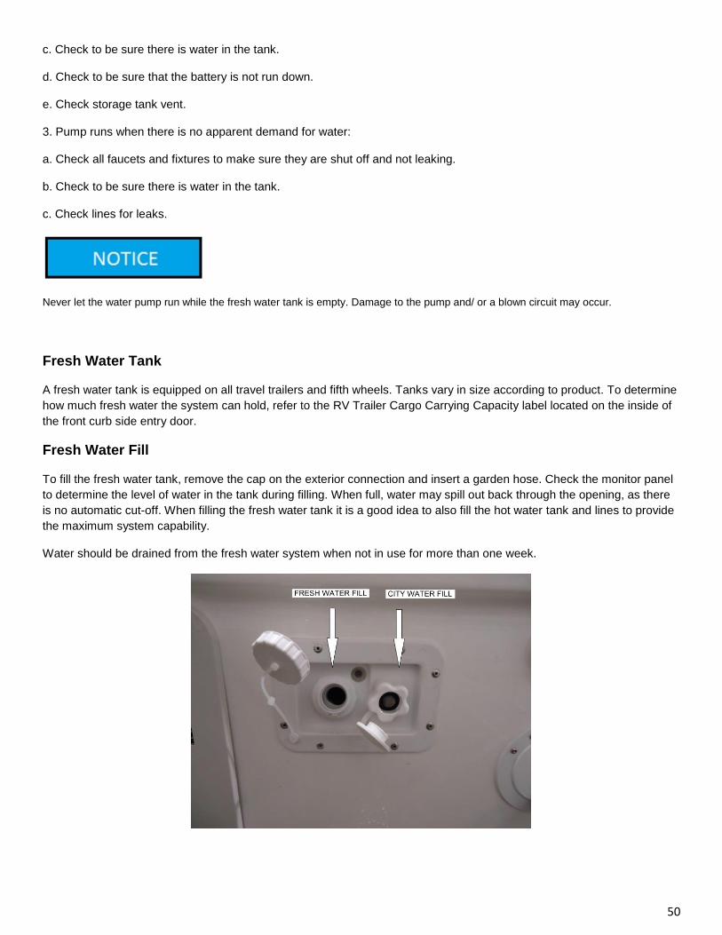
50
c. Check to be sure there is water in the tank.
d. Check to be sure that the battery is not run down.
e. Check storage tank vent.
3. Pump runs when there is no apparent demand for water:
a. Check all faucets and fixtures to make sure they are shut off and not leaking.
b. Check to be sure there is water in the tank.
c. Check lines for leaks.
Never let the water pump run while the fresh water tank is empty. Damage to the pump and/ or a blown circuit may occur.
Fresh Water Tank
A fresh water tank is equipped on all travel trailers and fifth wheels. Tanks vary in size according to product. To determine
how much fresh water the system can hold, refer to the RV Trailer Cargo Carrying Capacity label located on the inside of
the front curb side entry door.
Fresh Water Fill
To fill the fresh water tank, remove the cap on the exterior connection and insert a garden hose. Check the monitor panel
to determine the level of water in the tank during filling. When full, water may spill out back through the opening, as there
is no automatic cut-off. When filling the fresh water tank it is a good idea to also fill the hot water tank and lines to provide
the maximum system capability.
Water should be drained from the fresh water system when not in use for more than one week.
51
City Water Fill
The city water fill allows a direct connection to an outside source, such as campsites with water risers. There is no need to
use the water pump as the water coming from the exterior source is already pressurized and will bypass the pump and
tank. This connection has a sanitary plastic cover for protection when not in use. Connect the city water fill by using a
hose manufactured for potable water use. Open faucets and allow any air to be purged.
Sanitizing the Fresh Water System
Keeping the fresh water system clean and free of any potential contaminations is a top priority. Sanitizing the system
before initial use and thereafter annually, or whenever water remains unused for prolonged durations, is recommended.
This will help keep the water system fresh and discourage harmful bacterial or viral growth. To sanitize your system,
perform the following:
1. Drain the tank by opening the low point drain on the fresh water tank. Make sure water heater is not by-passed.
2. Prepare a chlorine bleach solution (¼ cup of bleach with 1 gallon of water) for every 15 gallons of tank capacity.
3. Add solution to tank and fill with water. Turn on pump and open each faucet/fixture until a distinct chlorine odor is
smelled. Close faucets and let stand 4 hours. Do not forget to turn on hot water taps as well as cold.
4. Completely drain system and flush with fresh water until chlorine odor and smell is gone. (If water filter has been added,
change it at this time).
A CONTAMINATED WATER SUPPLY CAN CAUSE SERIOUS INJURY OR DEATH.
About Vibration While Traveling
The fresh water system was thoroughly inspected for leaks before delivery. However, vibration during travel can loosen
fittings. Periodically check the fittings at the faucets and visible connections and tighten when necessary.
Water Heater
Carefully read the manufacturer’s manual for complete operational and safety instructions, provided in the unit packet,
prior to using the appliance.
The water heater in your trailer operates on propane, and is similar to the one in your home. It contains an automatic shut-
off valve which stops the gas flow if the water temperature rises too high. The water heater is reached through an access
panel on the outside of the trailer.
The water heater installed is a 6-gallon. Dependent upon the model installed, the water heater will operate only on gas or
on either gas or AC current (optional).
If an electric water heater is installed, the water heater circuit breaker must not be turned on until the water heater tank is
completely filled. Neither should the propane burner be ignited prior to completely filling the tank. To fill tank, make sure
water heater is not by-passed, then turn on the hot water faucet at the galley sink. If water flows continuously, the heater
is full. Tank must be filled with water prior to operating any type of water heater.
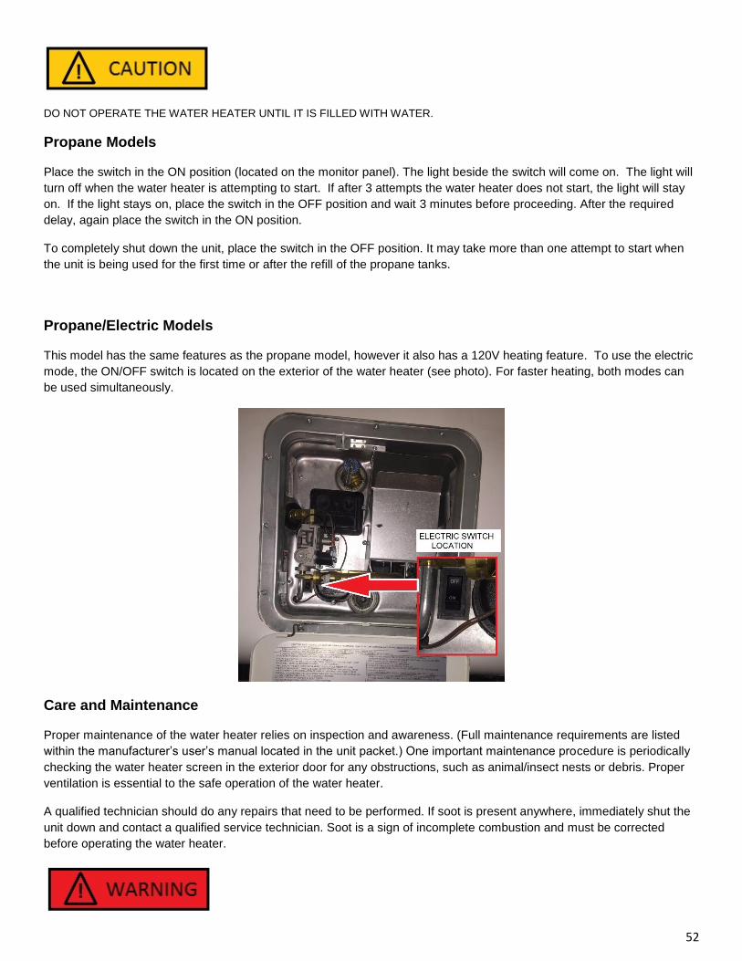
52
DO NOT OPERATE THE WATER HEATER UNTIL IT IS FILLED WITH WATER.
Propane Models
Place the switch in the ON position (located on the monitor panel). The light beside the switch will come on. The light will
turn off when the water heater is attempting to start. If after 3 attempts the water heater does not start, the light will stay
on. If the light stays on, place the switch in the OFF position and wait 3 minutes before proceeding. After the required
delay, again place the switch in the ON position.
To completely shut down the unit, place the switch in the OFF position. It may take more than one attempt to start when
the unit is being used for the first time or after the refill of the propane tanks.
Propane/Electric Models
This model has the same features as the propane model, however it also has a 120V heating feature. To use the electric
mode, the ON/OFF switch is located on the exterior of the water heater (see photo). For faster heating, both modes can
be used simultaneously.
Care and Maintenance
Proper maintenance of the water heater relies on inspection and awareness. (Full maintenance requirements are listed
within the manufacturer’s user’s manual located in the unit packet.) One important maintenance procedure is periodically
checking the water heater screen in the exterior door for any obstructions, such as animal/insect nests or debris. Proper
ventilation is essential to the safe operation of the water heater.
A qualified technician should do any repairs that need to be performed. If soot is present anywhere, immediately shut the
unit down and contact a qualified service technician. Soot is a sign of incomplete combustion and must be corrected
before operating the water heater.
53
HYDROGEN CAN BE PRODUCED IN THE WATER HEATER SYSTEM IF THE HEATER HAS NOT BEEN USED FOR A LONG TIME,
GENERALLY TWO WEEKS OR MORE. THIS IS ESPECIALLY TRUE IF THE WATER HEATER HAS BEEN DRAINED. HYDROGEN
GAS IS EXTREMELY FLAMMABLE. DUE TO THE RISK OF SERIOUS INJURY OR DEATH UNDER THESE CONDITIONS IT IS
RECOMMENDED THAT THE HOT WATER FAUCET BE OPENED FOR SEVERAL MINUTES AT THE KITCHEN SINK BEFORE
USING ANY ELECTRICAL APPLIANCES. IF HYDROGEN IS PRESENT THERE WILL PROBABLY BE AN UNUSUAL SOUND, LIKE
AIR ESCAPING THROUGH THE PIPE AS THE WATER BEGINS TO FLOW. THERE SHOULD BE NO SMOKING OR OPEN FLAME
NEAR THE WATER FAUCET WHEN IT IS OPENED.
Pressure Relief Valve - Weeping or Dripping
As in residential water heaters, the water heater equipped in recreational vehicles contains a pressure relief valve, located
behind the exterior water heater door. It is designed to open if the temperature of the water within reaches 210 degrees F
or if excessive pressure is built up. When pressure reaches 150 pounds, the relief valve will open and water will drip from
the valve. The valve will close automatically once the pressure falls below 150 pounds. This dripping is normal and does
not indicate a malfunctioning or defective valve.
Also, as water is heated, it expands and with the closed water system in a recreational vehicle, water expansion will cause
weeping at the pressure relief valve.
Water Supply and Odor
Water supplies sometimes contain high levels of sulphur, which causes an unpleasant smell, similar to rotten eggs. While
unpleasant, the water is not harmful. Sanitizing the water system, as described earlier and allowing the sanitizing solution
to remain for a few days, should eliminate the odor. Remember to thoroughly flush the system after sanitization. Adding a
filtration system will help reduce such occurrences.
Draining and Storage
When not using for long periods or storing during the winter months, the water heater must be drained to avoid damage
from freezing during the winter and/or deterioration of tank life from mineral content in water supplies.
To Drain the Water Heater
1. Turn off power to the water heater at the switch or the main breaker. 2. Shut off the gas supply and the water pump. 3. Open all fixtures, both hot and cold throughout the unit. 4. Place the bypass valve in the “by-pass” position. 5. Remove/open the exterior access door to the water heater. 6. Remove the drain plug (Anode Rod) from the tank. Water will drain out tank.
By-Pass Kit
The by-pass kit is a convenience feature that allows for easier drainage of the hot water heater tank and winterization of
the unit. The by-pass kit is installed near the water heater and allows for blockage of water flow into the water heater,
saving time and reducing the amount of anti-freeze needed during winterization.
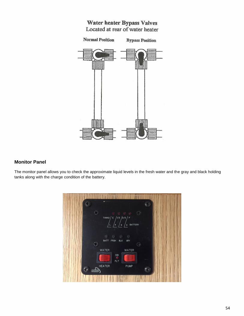
54
Monitor Panel
The monitor panel allows you to check the approximate liquid levels in the fresh water and the gray and black holding
tanks along with the charge condition of the battery.
55
Operation
Depress the button for the desired reading (battery or holding tanks.) The levels readout for the tanks will read as Empty
(E), 1/3, 2/3, or Full (F). The battery conditions are as follows:
L - Low, F - Fair, G – Good, C – Charge
Erroneous Readings
The monitor panel displays readings from sensors attached to the tanks. These sensors can send false readings when the
following conditions occur:
Water with low mineral content. Minerals in water help conduct the electrical signal to the monitor display. Some water,
which is very low in mineral content, may not conduct the signal properly. Although infrequent, this condition can exist.
Check the panel reading when the fresh water tank is filled.
The most common problem associated with the waste system is a false reading from the tank level indicators. This is
typically a result of a film build-up on the side walls of the holding tanks. To clean the interior of the tanks, close the
valves, fill the tanks about ½ full with hot water and small amount of automatic dish washer detergent then drive a
distance to agitate the solution within the tanks before draining the tanks at an approved disposal location.
Winterization
RV components can be damaged from the effects of freezing. Protection of the plumbing system and related components
is crucial. Damages due to weather are not covered under warranty at any time.
Many recreational vehicle owners choose to have their units winterized by an RV service center, while others choose to
do it themselves. Following are descriptions of methods used to winterize:
• Compressed Air (Dry) Method — Use compressed air to blow out any remaining water in the system after draining the
system of all water. This method requires an air compressor and appropriate adapters.
• RV Anti-Freeze (Wet) Method — Uses RV approved, nontoxic, potable, anti-freeze in the system and does not require
any special tools.
Following are procedures for both methods. If using the compressed air method, a special adapter (blow plug) is
necessary and should be purchased to allow compressed air to be delivered through the city water fill. These adapters are
available at most RV supply stores.
Method 1 - Compressed Air (Dry)
1. Purchase 1 gallon of RV non-toxic anti-freeze. 2. Drain the fresh water tank and empty the waste water holding tanks. 3. Turn water heater by-pass valves to by-pass position. (The by-pass valves are located near the water heater incoming lines.) 4. Drain water heater. (if equipped, switch 120V operation off) To do this, a 1-1/16” socket wrench is required to remove the anode rode. 5. Open all faucets, including shower head sprayer, toilet flushing device and any other water lines that are closed. 6. Turn on the water pump for 30 seconds to clear out any water in the lines. 7. Connect an air hose with an adapter (blow plug) to the city water fill connection. 8. Set the pressure no greater than 50 pounds and blow out the water lines until no water can be seen coming out of the fixtures and lines. Make sure you operate the toilet flush valve and shower diverters. 9. Pour anti-freeze down shower, lavatory sink, and kitchen sink to fill p-traps.
Method 2 - RV Anti-Freeze (Wet)
1. Purchase 2-3 gallons of RV approved, non-toxic anti-freeze.
56
2. Drain all tanks, fresh water and sewage tanks. 3. Turn water heater by-pass valves to by-pass position. (The by-pass valves are located near the water heater incoming lines.) 4. Drain water heater. 5. Pour an amount of RV non-toxic anti-freeze into the fresh water tank to fill the tank above minimum water pump operating level. (Use of a long funnel may be helpful) Add more, if necessary, during procedure. 6. Turn on pump switch and open the cold water side of all faucet fixtures including shower head. Leave open until the anti-freeze comes out (generally, pink in color). Repeat for hot water side. 7. Flush toilet until anti-freeze begins to flow into the bowl and then pour one gallon of anti-freeze down the toilet to winterize the black tank. 8. Pour anti-freeze down shower, lavatory sink, and kitchen sink to fill p-traps.
DO NOT USE AUTOMOTIVE ANTI-FREEZE. AUTOMOTIVE ANTI-FREEZE IS POISONOUS AND NOT FOR USE IN POTABLE
WATER SYSTEMS.
De-winterization/Removal of Anti-freeze
If purchasing a trailer which is winterized with RV anti-freeze, or having had an existing unit winterized before winter
storage, the plumbing system must be flushed and sanitized prior to use. Do Not Attempt to turn on water heater if system
is winterized. Perform the following prior to attempting to operate the water heater or use the plumbing system.
1. Drain fresh water tank. 2. Attach garden hose to fresh water fill and fill tank. 3. Turn on pump switch and open cold water side of all faucet/shower fixtures. Leave open until water runs clear. Repeat for hot water side. 4. Flush toilet until clear water runs into bowl. 5. Empty fresh water tank. (And holding tanks as necessary) 6. Sanitize water system. (See earlier section in this chapter)
Waste Water System
The wastewater system inside the recreational vehicle is self-contained while on the road or set up in a campsite. The
main parts of the waste system are the toilet, holding tanks and tank dump valves. As in residential households, the
drainage system also includes p-traps and roof vents to allow escape of odors and gases.
Toilet
The toilet operates from water supplied either by the fresh water tank or from an exterior water supply connected at the
city water hook-up. (The water pump must be turned on when utilizing the water from the fresh water tank.) The toilet
flushes directly into the black water tank. Complete instructions and care for the model installed are located in the unit
packet.
Do not put these items in toilet or drains
1. Facial tissues, paper towels, sanitary products (including those labeled flushable). 2. Automotive antifreeze, ammonia, alcohols, or acetones. 3. Grease from cooking, table scraps or other solids that may cause clogging.
Holding Tanks
Waste water is divided into two categories: Black water and gray water. The term black water refers to the waste flushed
down the toilet and stored in a separate tank, or referred to as the black tank. Gray water is the wastewater from the sinks
57
and shower drains and is stored within one gray tank. Waste tanks empty through a single outlet, but a separate valve
controls each tank.
The dump valves should remain closed even if connected to an exterior sewer hook up. For proper dumping, empty tanks
only when they are nearly full. The idea is to send a large volume of water through the tanks and hose at the same time to
assist the solid waste in flushing from the system. Otherwise solids may build up and harden inside tank.
Dumping Instructions
1. Be sure unit is reasonably level so tanks can fully drain. 2. Twist off the termination outlet cap. 3. Connect the sewer hose by turning clockwise, locking the end levers over the termination end. 4. Place the other end of the sewer hose into an approved dump station inlet. 5. Open the black tank termination valve and drain. (Always dump black tank first so gray water washes out hose) 6. You may want to close the black tank valve and refill tank half full by engaging the toilet flush valve. Then open the termination valve for the black tank, dumping it again. 7. Open the gray tank termination valve and drain 8. Close termination valves. 9. Disconnect sewer hose and store. 10. Replace termination cap on the outlet. 11. Add chemical deodorant/breakdown agent approved for RV use. After the sewage tank has been emptied, close the gate valves and put approximately 2 litres of water in the sewage
(black water) holding tank. This will help prevent solids from building up. The addition of a deodorizing agent like Aqua-
Kem® will help prevent odors.
NOTE: Termination cap must be in place at all times except when connected to sewer.
58
Chapter 8: Care and Maintenance
The instructions and recommendations located within this manual and the accompanying manufacturer’s component
literature should be read, as failure to perform necessary or preventative maintenance may limit or void all or part of a
specific warranty.
Care and maintenance of the recreational vehicle is an important step in maintaining the safety, dependability and the
appearance, both interior and exterior, of the unit. Keep good records of all maintenance performed as these may be
necessary for warranty information or may assist in possible repairs needed.
Operational usage and climates may affect the frequency of maintenance needed on certain components. Preventative
maintenance is important to the life and enjoyment of any recreational vehicle as many problems can be caught before
they occur. Please do not hesitate to call your dealer with a question on the maintenance or care of any item.
The care and maintenance of appliances are discussed within the appliance chapter. Always refer to the manufacturer’s
recommendations located within the literature contained within the unit packet.
Exterior
Fiberglass/Gel Coat Finish
Care of the fiberglass finish is similar to caring for a new car. Any finish will deteriorate over time. Exposure to extreme
sunlight, pollutants, and excessive moisture can cause dulling, fading and yellowing. Regular washing and periodic
waxing will help maintain the glossy new look. When washing, use a mild, automotive or RV wash solution, being sure to
rinse off any loose debris first. Avoid spraying water directly into the furnace and refrigerator vents. Waxing the fiberglass
areas twice a year is recommended. Wax with an automotive wax or polish developed for boats. Follow all directions by
the wax manufacturer carefully and remember to wash and wax out of direct sunlight and when surfaces are cool.
Seals and Adhesives
The seals and adhesives used perform an important job, keeping out an RV enemy — water. Close inspection and routine
maintenance are crucial to the longevity of the trailer. While many types are used, none have a pre-set lifetime, as
exposure to the elements and regional variances of climate can accelerate any sealant’s deterioration. Therefore, every
six months, inspection of all seals is recommended and a quick inspection prior to every trip will help reduce potential
problems down the road.
When inspecting, check for cracks, voids, shrinkage, or any sign of deterioration. If any of these signs are noticed, have
your local RV service center inspect and replace the sealant if necessary. It is important to use the same kind of sealant
that was previously used.
Doors and Windows
Door Catches —The door lock design reflects the latest safety regulations. It is very important that the door be completely
closed and locked during travel. If you find it is difficult to lock the door, push in to release pressure on the door latch while
turning the key. The door is locked from the inside by pushing or turning a button near the door handle
59
Windows (Exterior)
As with seals, check the sealant around the windows at least once every six months. If any interior leaks are noticed,
contact an authorized dealer immediately. To ensure window operation, adjust and lubricate latches and any moving parts
annually. A light oil or powdered graphite can be used for lubrication. Periodically use a vacuum attachment to clean any
debris out of the window weep holes, which are necessary to drain any condensation moisture or from hard driving rains
that may collect.
Windows and window glass meet or exceed all federal safety standards. They require only normal care and may be
cleaned with any good glass cleaner.
Window screens are made of plastic for longer wear and ease of maintenance. They can be easily cleaned with a mild
cleaning solution.
Frame and Chassis
Over time, weather and climate such as rain, snow, salt, etc lead to corrosion. Rinse the undercarriage, wheel wells, hitch
and bumper when needed to remove dirt, oil, tar, salt and other debris. Periodically inspect for rust. Near coastal regions,
inspect more frequently. If needed, lightly sand and repaint with a rustproof enamel.
Hitch Couplers
Inspect prior to each trip. The ball socket and clamp should be cleaned and lubricated monthly with wheel bearing grease.
If coupler or coupler components appear damaged or worn, contact your local RV service center upon notice of the
problem.
Fifth Wheel Coupler
Inspect monthly or prior to each trip. The hitch plate and locking mechanism should be generously lubed at all times with a
high temperature rated grease. Consult the paperwork that accompanied the hitch purchased for manufacturer
recommendations. Bolts should be torqued to 160 ft. lbs
Safety Chains
Safety chains should be inspected monthly. If chains are damaged or weakened, replace immediately. Never tow without
use of the safety chains.
Tires and Wheels
The tires should be checked before starting out on any trip. Check them regularly and keep inflated to recommended
pressures. The recommended tire pressure is on the side of the tire. Even with good tire maintenance and normal driving,
you may experience a flat tire. Summon professional roadside assistance from your auto club, travel service, or local truck
service facility.
Your travel trailer is not equipped with a jack or other lifting device.
Wheel Nut Torque
The axle and wheel assemblies of your RV are designed differently than those on your car. The overall size, weight and
center of gravity of a recreational vehicle subject the wheels to pressures unique to trailering. During normal cornering, the
tires and wheels experience a considerable amount of stress called “side-load”. Therefore, the lug nuts on your
recreational vehicle require periodic re-torquing.
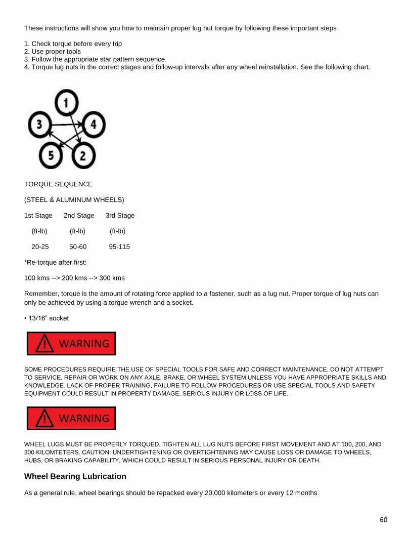
60
These instructions will show you how to maintain proper lug nut torque by following these important steps
1. Check torque before every trip 2. Use proper tools 3. Follow the appropriate star pattern sequence. 4. Torque lug nuts in the correct stages and follow-up intervals after any wheel reinstallation. See the following chart.
TORQUE SEQUENCE
(STEEL & ALUMINUM WHEELS)
1st Stage 2nd Stage 3rd Stage
(ft-lb) (ft-lb) (ft-lb)
20-25 50-60 95-115
*Re-torque after first:
100 kms --> 200 kms --> 300 kms
Remember, torque is the amount of rotating force applied to a fastener, such as a lug nut. Proper torque of lug nuts can
only be achieved by using a torque wrench and a socket.
• 13/16” socket
SOME PROCEDURES REQUIRE THE USE OF SPECIAL TOOLS FOR SAFE AND CORRECT MAINTENANCE. DO NOT ATTEMPT
TO SERVICE, REPAIR OR WORK ON ANY AXLE, BRAKE, OR WHEEL SYSTEM UNLESS YOU HAVE APPROPRIATE SKILLS AND
KNOWLEDGE. LACK OF PROPER TRAINING, FAILURE TO FOLLOW PROCEDURES OR USE SPECIAL TOOLS AND SAFETY
EQUIPMENT COULD RESULT IN PROPERTY DAMAGE, SERIOUS INJURY OR LOSS OF LIFE.
WHEEL LUGS MUST BE PROPERLY TORQUED. TIGHTEN ALL LUG NUTS BEFORE FIRST MOVEMENT AND AT 100, 200, AND
300 KILOMTETERS. CAUTION: UNDERTIGHTENING OR OVERTIGHTENING MAY CAUSE LOSS OR DAMAGE TO WHEELS,
HUBS, OR BRAKING CAPABILITY, WHICH COULD RESULT IN SERIOUS PERSONAL INJURY OR DEATH.
Wheel Bearing Lubrication
As a general rule, wheel bearings should be repacked every 20,000 kilometers or every 12 months.
61
Carefully read the component manufacturer’s manual and any safety instructions provided in the unit packet prior to
performing any maintenance.
EZ Lube
If the trailer is equipped with EZ Lube axles, there is no need to remove hubs to grease axle bearings. Periodic greasing
will prolong the need to repack the bearings. To grease follow these simple steps:
1. Raise the tire off the ground
2. Remove the rubber plug from the grease cap
3. Insert grease gun on the grease zerk
4. Spin the tire while slowly pumping grease gun (3 pumps per wheel)
5. Replace rubber plug
Hubs and components still need to be inspected and maintained per the manufacturer’s guidelines. Carefully read the component manufacturer’s manual and any safety instructions provided in the unit packet prior to
performing any maintenance.
Brake Adjustment
The electric brakes are of the drum and two-shoe type and adjust the same as most automotive brakes. Adjust brakes
after the first 500 kilometers. Every 3 months or 5000 kilometers, test the brake drag and adjust if required. Full
procedures are outlined in the component manufacturer’s guide, included in the unit packet. Never adjust just one brake.
When adjusting brakes on any vehicle, either replace or adjust all brakes at the same time, or at least both brakes on the
same axle. Also see Braking Section in Chapter 3.
Battery
A fully charged battery is 12.6V and a flat battery is 10.6V. A good rule of thumb to maintain the life of the battery is to try
not let the voltage drop below 50% which would be 11.6V. Once the static voltage reaches around 50%, you should start
looking to charge the batteries.
Before performing any maintenance on the battery, always disconnect the battery cables from the battery. To inspect the
electrolyte level, remove the vent covers and visually ascertain the electrolyte level in each cell. Using a small flashlight
may help. If the level needs to be replenished in any or all cells, carefully pour in distilled water only. DO NOT OVERFILL,
LEAVE ROOM FOR EXPANSION Never use acid or tap water. Tap water contains minerals and chemical impurities that
will permanently damage the battery. Besides maintaining the electrolyte level, visually inspect the battery for loose
terminals, corrosion, or any damage to the vent covers or case. Tighten any loose clamps on the terminals of the battery
and clean any corrosion off the terminals.
When working with batteries, be extremely careful. The acid in batteries is highly corrosive and flammable. Batteries
produce a flammable hydrogen gas that will explode if ignited. Never place batteries in any compartment or near anything
that could spark, even a 12 Volt switch. Never smoke or use open flames anywhere near the battery. Never inhale fumes
from battery cells. Secure batteries in a battery box or in a compartment specially designed for battery storage. Wear
safety glasses and appropriate clothing when performing any maintenance on a battery. In case of a spill or splash,
immediately flush the affected area with cold water for 15 minutes and call the poison control center for further
instructions.
Battery Storage
When storing the RV for an extended period, fully charge the battery before storage. Batteries will self-discharge over time
and are subject to freezing, especially if in a discharged condition. Inspect batteries while in storage every 2 to 3 weeks.
Hook up a battery charger at least once a month to prevent discharge and sulfation. An easy solution is to remove the
battery completely from the unit during storage and place it at home in a warmer location, such as a garage, so that the
battery condition can be monitored and charged as needed during storage periods.
62
Blinds and Shades
Shades should be vacuumed regularly with a soft brush attachment. For fabric shades, upholstery cleaners are not
recommended. Instead, spot clean when necessary, using a mild soap and water solution on area.
Cabinet Doors and Drawers (Wood)
The cabinet doors and drawer fronts should be cared for similar to the fine furniture in your home. Using a quality furniture
polish will help maintain the beauty and luster of the wood as well as keep the wood from drying out. The accidental
scratches can be covered satisfactory with a good quality commercial furniture scratch remover.
Ceilings and Walls
Clean only with a mild detergent in warm water, using a damp cloth. Never use strong chemicals, as they can damage the
ceiling or walls.
Countertops
Countertops are made of high-pressure plastic laminates and are highly resistant to normal spills and scuffs. Soap and
lukewarm water or a mild, non-abrasive cleaner are recommended.
Avoid use of abrasive pads and scouring powders, which can dull the surface and make it more stain-prone. Always use a
chopping block or cutting board when using knives. Pots and pans straight from the burner or oven should be placed on
lined hot pads and not directly on the counter surface.
Faucets and Fixtures
To protect the finishes on your kitchen and bath faucets and fixtures, use only a damp soft cloth or sponge. Do not use
abrasive cleaners or materials as they can damage the finish.
Flooring, Vinyl
For routine cleaning, sweep or vacuum regularly. Follow by using a damp mop with warm water and clean a small area at
a time. Rinse the mop frequently as to not redistribute the picked up dirt. If washing is needed, use a quality product
designed for no-wax flooring. To polish the floor, do not use solvent-based waxes or polishes as damage to the flooring
may result. Use only polishes recommended for no-wax flooring.
Glass and Mirrors
Clean glass and mirrors as you would at home using a cleaner designed for glass. To reduce “spotting” on outside
windows, use a squeegee promptly after rinsing with water. For stubborn spots, cleaning with a mixture of vinegar and
water is recommended and is safe for most finishes.
63
Fabric and Upholstery
Do not launder upholstery fabrics. Blot up stains promptly and use an upholstery cleaner or mild solvent, depending on
the stain. Never soak the fabric and use as little water as possible. Blot rather than rub. Towel dry or have professionally
cleaned. Upholstery can be vacuumed regularly using a soft brush attachment.
Sinks and Toilet
Many of these products are made of acrylics, plastics or composite materials and use of non-abrasive cleaners is
recommended to protect the finish. Use of harsh cleaning products can cause premature deterioration and/or yellowing of
the surface finish.
Storage
If you plan to store your recreational vehicle for a prolonged period of time you should perform the following procedures to
protect and maintain your vehicle.
Propane System
Close the propane container’s service valve. Extinguish all pilots and close all appliance propane valves (oven/range,
water heater, refrigerator, furnace).
Plumbing System
Follow procedures for winterization in plumbing chapter.
Smoke Detector
Remove batteries.
Electrical System
Turn off all circuit breakers at the service panel.
Interior
Close and secure all doors and windows. Open the Maxx Fan slightly to allow circulation.
Refrigerator
Remove any food, etc. and block door open slightly. This will prevent odor and reduce chance for mildew or mold to
develop. It is a good idea to leave a small open box of baking soda inside refrigerator while in storage.
Battery
See page 62 for storage instructions
64
Chapter 9: Tire Safety Information
Understanding Tire Pressure and Load Limits
Tire inflation pressure is the level of air in the tire that provides it with load-carrying capacity and affects the overall
performance of the vehicle. The tire inflation pressure is a number that indicates the amount of air pressure - measured in
pounds per square inch (psi) - a tire requires to be properly inflated. (You will also find this number on the vehicle
information placard expressed in kilopascals (kPa), which is the metric measure used internationally.)
Tire Pressure
It is important to check your vehicle’s tire pressure at least once a month for the following reasons:
• Most tires may naturally lose air over time
• Tires can lose air suddenly if you drive over a pothole or other object or if you strike the curb when parking
The recommended tire inflation pressure that vehicle manufacturers provide reflects the proper psi when a tire is cold. The
term cold does not relate to the outside temperature. Rather, a cold tire is one that has not been driven on for at least
three hours. When you drive, your tires get warmer, causing the air pressure within them to increase. Therefore, to get an
accurate tire pressure reading, you must measure tire pressure when the tires are cold or compensate for the extra
pressure in warm tires.
Tire Size
To maintain tire safety, purchase new tires that are the same size as the vehicle’s original tires or another size
recommended by the manufacturer. Look at the tire information placard, the owner’s manual, or the sidewall of the tire
you are replacing to find this information. If you have any doubt about the correct size to choose, consult with the tire
dealer.
Tire Tread
The tire tread provides the gripping action and traction that prevent your vehicle from slipping or sliding, especially when
the road is wet or icy. In general, tires are not safe and should be replaced when the tread is worn down to 1/16 of an
inch. Tires have built-in tread-wear indicators that let you know when it is time to replace your tires. These indicators are
raised sections spaced intermittently in the bottom of the tread grooves. When they appear “even” with the outside of the
tread, it is time to replace your tires.
Tire Balance
To avoid vibration or shaking of the vehicle when a tire rotates, the tire must be properly balanced. This balance is
achieved by positioning weights on the wheel to counterbalance heavy spots on the wheel-and-tire assembly.
Tire Repair
The proper repair of a punctured tire requires a plug for the hole and a patch for the area inside the tire that surrounds the
puncture hole. Punctures through the tread can be repaired if they are not too large, but punctures to the sidewall should
not be repaired. Tires must be removed from the rim to be properly inspected before being plugged and patched.
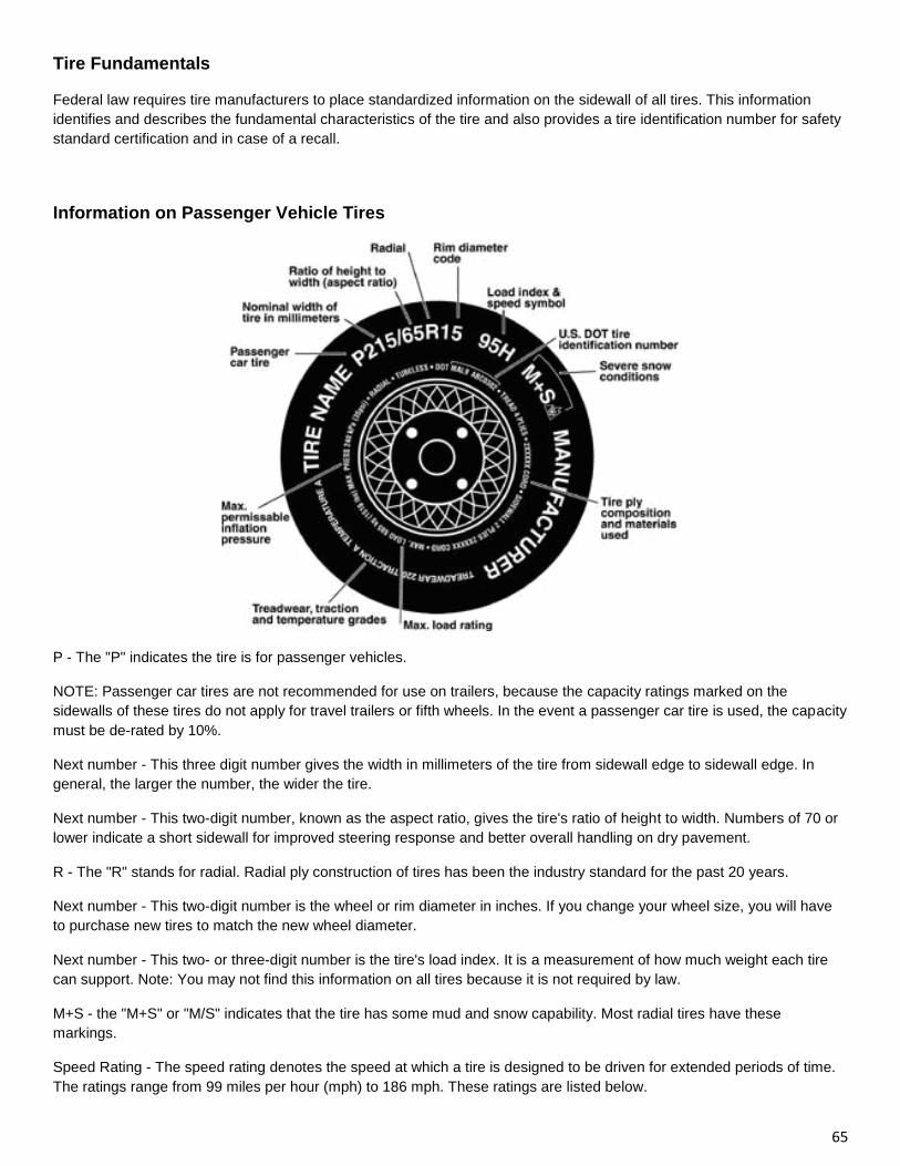
65
Tire Fundamentals
Federal law requires tire manufacturers to place standardized information on the sidewall of all tires. This information
identifies and describes the fundamental characteristics of the tire and also provides a tire identification number for safety
standard certification and in case of a recall.
Information on Passenger Vehicle Tires
P - The "P" indicates the tire is for passenger vehicles.
NOTE: Passenger car tires are not recommended for use on trailers, because the capacity ratings marked on the
sidewalls of these tires do not apply for travel trailers or fifth wheels. In the event a passenger car tire is used, the capacity
must be de-rated by 10%.
Next number - This three digit number gives the width in millimeters of the tire from sidewall edge to sidewall edge. In
general, the larger the number, the wider the tire.
Next number - This two-digit number, known as the aspect ratio, gives the tire's ratio of height to width. Numbers of 70 or
lower indicate a short sidewall for improved steering response and better overall handling on dry pavement.
R - The "R" stands for radial. Radial ply construction of tires has been the industry standard for the past 20 years.
Next number - This two-digit number is the wheel or rim diameter in inches. If you change your wheel size, you will have
to purchase new tires to match the new wheel diameter.
Next number - This two- or three-digit number is the tire's load index. It is a measurement of how much weight each tire
can support. Note: You may not find this information on all tires because it is not required by law.
M+S - the "M+S" or "M/S" indicates that the tire has some mud and snow capability. Most radial tires have these
markings.
Speed Rating - The speed rating denotes the speed at which a tire is designed to be driven for extended periods of time.
The ratings range from 99 miles per hour (mph) to 186 mph. These ratings are listed below.
66
Q 99 mph
R 106 mph
S 112 mph
T 118 mph
U 124 mph
H 130 mph
V 149 mph
W 168* mph
Y 186* mph
U.S. DOT Tire Identification Number - This begins with the letters "DOT" and indicates that the tire meets all federal
standards. The next two numbers or letters are the plant code where it was manufactured, and the last four numbers
represent the week and year the tire was built. For example, the numbers 3197 means the 31st week of 1997. The other
numbers are marketing codes used at the manufacturer's discretion. This information is used to contact consumers if a
tire defect requires a recall.
Tire Ply Composition and Materials Used - The number of plies indicates the number of layers of rubber-coated fabric in
the tire. In general, the greater the number of plies, the more weight a tire can support. Tire manufacturers also must
indicate the materials in the tire, which include steel, nylon, polyester, and others.
Maximum Load Rating - This number indicates the maximum load in kilograms and pounds that can be carried by the tire.
Maximum Permissible Inflation Pressure - This number is the greatest amount of air pressure that should ever be put in
the tire under normal driving conditions.
Tires for light trucks have other markings besides those found on the sidewalls of passenger tires.
LT - the "LT" indicates the tire is for light trucks or trailers.
ST - An "ST" is an indication the tire is for trailer use only.
Max. Load Single kg (lbs) at kPa (psi) Cold - This information indicates the maximum load and tire pressure when the tire
is used as a single.
Load Range - This information identifies the tire's load-carrying capabilities and its inflation limits.
Exterior Pre-Travel Checklist
• Fill the propane bottles
• Empty the holding tanks
• Connect the trailer to the tow vehicle and test all of the exterior lights
• Inspect the awning and ensure that it is properly retracted and secured for travel.
• Inspect all exterior baggage doors and hatches ensuring they are locked
• Inspect the tires and check the pressures. Refer to Chapter 9
• Torque the lug nuts. Refer to Chapter 9
67
• Secure the rear leveling jacks in the “up” position
• Connect the breakaway switch and test the brakes on the trailer. Adjust the tow vehicle brake controller in accordance
with the manufacturer’s recommendations
• Position the battery disconnect (if equipped) to the “on” position. This is required to charge the batteries while in tow.
• Ensure the steps are retracted.
Interior Pre-Travel Checklist
• Close all vents and windows
• Inspect the interior of the unit ensuring that all doors are closed table is secured
• Secure all loose items in storage compartments
• Test the smoke, carbon monoxide and propane alarms
Battery
• Check the electrolyte levels in the battery cells. Refer to Chapter 5
• Clean the battery terminals and ensure they are securely tightened. Refer to Chapter 5
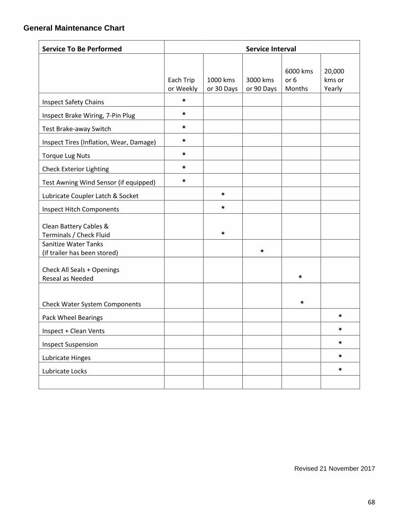
68
General Maintenance Chart
Service To Be Performed Service Interval
Each Trip or Weekly
1000 kms or 30 Days
3000 kms or 90 Days
6000 kms or 6 Months
20,000 kms or Yearly
Inspect Safety Chains *
Inspect Brake Wiring, 7-Pin Plug *
Test Brake-away Switch *
Inspect Tires (Inflation, Wear, Damage) *
Torque Lug Nuts *
Check Exterior Lighting *
Test Awning Wind Sensor (if equipped) *
Lubricate Coupler Latch & Socket *
Inspect Hitch Components *
Clean Battery Cables & Terminals / Check Fluid * Sanitize Water Tanks (if trailer has been stored) *
Check All Seals + Openings Reseal as Needed *
Check Water System Components *
Pack Wheel Bearings *
Inspect + Clean Vents *
Inspect Suspension *
Lubricate Hinges *
Lubricate Locks *
Revised 21 November 2017