Embed Size (px)
Citation preview
SLEEPERS AND TRACK SUPPORT
ESC 230
Engineering Standard Track
Version 4.8
Issued April 2013
En
gin
eeri
ng
Sta
nd
ard
Owner: Chief Engineer, Track
Approved by:
Andrew Wilson Technical Specialist Wheel/Rail
Authorised by:
Malcolm Kerr Chief Engineer Track
Disclaimer
This document was prepared for use on the RailCorp Network only.
RailCorp makes no warranties, express or implied, that compliance with the contents of this document shall be sufficient to ensure safe systems or work or operation. It is the document user’s sole responsibility to ensure that the copy of the document it is viewing is the current version of the document as in use by RailCorp.
RailCorp accepts no liability whatsoever in relation to the use of this document by any party, and RailCorp excludes any liability which arises in any manner by the use of this document.
Copyright
The information in this document is protected by Copyright and no part of this document may be reproduced, altered, stored or transmitted by any person without the prior consent of RailCorp.
UNCONTROLLED WHEN PRINTED Page 1 of 31
RailCorp Engineering Standard — Track Sleepers and Track Support ESC 230
Document control
Version Date Summary of change 1 October 2006 First issue as a RailCorp document. Includes content from
C 3108, C 3109, C 5200, BI 1126, TS 3101, TS 3306, TS 3341, TS 3397, CTN 04/06, CTN 04/17.
2 April 2007 Minor corrections; inclusion of spacing requirements at bridge ends; inclusion of polymer concrete half sleepers.
3 October 2007 Inclusion of requirement to keep concrete sleepers clear of points; addition of requirement for use of HD concrete sleepers adjacent to TT bridge ends; clarification of use of recycled timber sleepers; clarification of use of low profile clips; addition to approved products; clarification of use of fastening repair process.
4 May 2008 Section 5.1.4.4 – Addition of boring requirements for timber sleepers, transoms and bearers; Section 5.7.2 – Correction of caption on Table 14; Section 5.9.2 and 5.9.3 – Clarification of application of fastening systems to bridge transoms; Section 5.9.3 – Clarification of fastening requirements for timber bearers. Appendix 1 – Updating of approved products.
4.1 December 2008 New Section 5.1.6 – limits on short sleeper ends; Section 5.9.2 – Inclusion of reference to threaded inserts.
4.2 May 2009 Format change; Section 4.9.6 - Resilient fastenings on bridges – addition of requirements for use of resilient fastenings on concrete and masonry bridges; Appendix 1 Approved sleeper and fastening products – Inclusion of Clouth alternative 1 sleeper plates.
4.3 December 2009 Section 4.9.5 – additional requirements for Direct Fixation Track; New Section 4.9.7.4 ZLR assemblies; New section 8.2 Acceptance limits for direct fixation track systems; Section 8.3 renumbered; Section 9 - Damage limits added; Appendix 1 - Addition of approved Pandrol S series plates.
4.4 July 2010 Appendix 1 - Minor additions to description of approved products.
4.5 February 2011 Section 4.9.4 – Table 19 Additional detail of approved Fastclip fastenings; Section 4.9.6.3 - addresses expansion of ballast top bridges; App 1- Additional approved components and suppliers.
4.6 August 2011 Section 4.9.4 - Addition of recommended use of elastomeric rail pads adjacent to timber sleepers or turnouts; Section 4.9.5 - Addition of requirement for thicker HDPE pads when used with resilient baseplates and epoxy grout
4.7 April 2012 Reformatted to new template 4.8 April 2013 Changes detailed in Summary table below.
Summary of changes from previous version
Summary of change Section
Control Changes Document Control
Changed dimension for length of timber bearers 4.6.2
© RailCorp Page 2 of 31 Issued April 2013 UNCONTROLLED WHEN PRINTED Version 4.8
© RailCorp Page 3 of 31Issued April 2013 UNCONTROLLED WHEN PRINTED Version 4.8
RailCorp Engineering Standard — TrackSleepers and Track Support ESC 230
Contents
1 Purpose, Scope and Application...........................................................................................4
2 References...............................................................................................................................4
2.1 Australian and International Standards.....................................................................................4
2.2 RailCorp Documents .................................................................................................................4
2.3 Other References......................................................................................................................4
3 Design & Performance Criteria..............................................................................................4
3.1 Track Configuration...................................................................................................................4
3.2 Sleepers and Bearers ...............................................................................................................5
3.3 Fastening Assembly Design .....................................................................................................5
4 Allowable Configurations.......................................................................................................6
4.1 Timber Sleepers........................................................................................................................6
4.2 Concrete Sleepers ....................................................................................................................9
4.3 Direct Fixation .........................................................................................................................10
4.4 Polymer Concrete Sleepers ....................................................................................................11
4.5 Concrete Guard Rail Sleepers ................................................................................................11
4.6 Timber Turnout Bearers ..........................................................................................................11
4.7 Concrete Turnout Bearers.......................................................................................................13
4.8 Steel Turnout Bearers .............................................................................................................13
4.9 Fastening Systems..................................................................................................................13
5 Prohibited Configurations....................................................................................................20
6 Mixed Configurations ...........................................................................................................20
7 Changing Configurations.....................................................................................................21
8 Acceptance Standards .........................................................................................................21
8.1 General....................................................................................................................................21
8.2 Direct Fixation Track System (slab track) ...............................................................................21
8.3 Sleeper Plates.........................................................................................................................22
9 Damage Limits.......................................................................................................................22
10 Repair Standards ..................................................................................................................23
10.1 Timber Sleepers and Bearers .................................................................................................23
10.2 Concrete Sleepers and Bearers..............................................................................................23
10.3 Fastenings...............................................................................................................................23
Appendix A Approved Sleeper and Fastening Products........................................................24
Appendix B Approved Repair Processes.................................................................................30
Appendix C Sleeper Boring Patterns........................................................................................31
RailCorp Engineering Standard — Track Sleepers and Track Support ESC 230
1 Purpose, Scope and Application This Standard establishes functional and design requirements, approved configurations, acceptance and repair standards for sleepers, turnout bearers, and sleeper fastenings. It also includes requirements for concrete guard rail sleepers and fastening requirements for transoms.
It is applicable to all Rail Corporation main line and siding tracks.
2 References
2.1 Australian and International Standards
n
AS 1085.3 (2002) - Railway Track Material Part 3: Sleeper plates
AS 1085.8 (2002) - Railway Track Material Part 8: Dogspikes
AS 1085.13 (2002) - Railway Track Material Part 13: Spring fastening spikes for sleeper plates
AS 1085.14 (2003) – Prestressed Concrete Sleepers
AS 1085.18 (2003) - Railway Track Material Part 18: Screwspikes and threaded inserts
AS 1085.19 (2003) - Railway Track Material Part 19: Resilient fastening assemblies
AS 3818.2 (2002) - Timber - Heavy structural products - Visually graded - Railway track timbers
2.2 RailCorp Documents ESC 200 - Track System
ESC 220 - Rail and Rail Joints
ESC 362 - Track Slabs
SPC 231 - Timber Sleeper and Bearer Specificatio
SPC 232 - Concrete Sleeper Specification
SPC 233 - Concrete Bearer Specification
SPC 234 – Resilient Fastening Specification
SPC 235 - Resilient Baseplate Specification
2.3 Other References Nil
3 Design & Performance Criteria
3.1 Track Configuration The configuration of track elements, including sleepers, turnout bearers, and sleeper fastenings is specified in ESC 200 Track System.
© RailCorp Page 4 of 31 Issued April 2013 UNCONTROLLED WHEN PRINTED Version 4.8

RailCorp Engineering Standard — Track Sleepers and Track Support ESC 230
3.2 Sleepers and Bearers This standard has been developed in consideration of the following criteria:
Loading
• Service loads (and dynamic response) including effects of track alignment, maintenance standards, and traffic task.
• Resistance to impact loading (e.g. wheel flats). • Rail seat loads, sleeper bending moments, rail to sleeper pressure and sleeper to
ballast pressure.
Materials
• Sleeper material, type and spacing. • Sleeper acceptance, inspection and testing requirements, and assessment of
effectiveness prior to insertion in track. • Sleeper life and treatment (e.g. timber preservatives). • Deterioration of the sleeper material (e.g. rust, concrete reactivity, fungal rot, white
ant attack).
Interfaces with other rail infrastructure
• Track circuit requirements. • Support of point switching equipment where necessary.
Support Requirements
• Track support conditions and deflection criteria. • Required track modulus.
Performance requirements
• Need to provide resistance to the lateral buckling of the track. • Need to provide effective support, positioning and restraint of the rail (in
conjunction with the rail fastening system). • Geometric requirements including the length and orientation of bearers in points
and crossings structures.
3.3 Fastening Assembly Design The factors to be considered in determining rail to sleeper fastening assembly design should include the following:
Loading
• Service loads (and dynamic response) including effects of track alignment, maintenance standards, and traffic task.
• Attenuation of vertical impact loads and vibration. • Pressure transmitted to the sleeper rail seat, for example the need for sleeper
plates on timber sleepers. • Need to control damage to sleepers by rail seat abrasion.
Interfaces with other rail infrastructure
• The need to provide electrical insulation where required to enable track circuits to work or to avoid current leakage.
© RailCorp Page 5 of 31 Issued April 2013 UNCONTROLLED WHEN PRINTED Version 4.8
RailCorp Engineering Standard — Track Sleepers and Track Support ESC 230
Support Requirements
• Required track modulus.
Performance requirements
• The need to provide effective support, positioning and restraint of the rail (in conjunction with the sleepers and bearers).
• The need to hold rails to gauge and at the correct inclination when subjected to lateral forces caused by vehicle curving, track alignment irregularities and wheelset steering and hunting.
• The need to provide lateral and torsional restraint (in the horizontal track plane) to the rail against buckling in hot weather.
• The need to provide rail longitudinal creep resistance when the rail is subjected to thermal loads and vehicle braking and traction forces.
4 Allowable Configurations
4.1 Timber Sleepers
4.1.1 Selection
Sleeper type shall be selected in accordance with the existing or proposed track structure class detailed in RailCorp standard ESC 200.
For the design of new lines, the beam on elastic foundation (BOEF) analysis may be used to determine sleeper size and spacing.
For existing applications in ballasted plain track, detailed in ESC 200, sleeper size shall meet the requirements of Section 4.1.2 and the standard spacing shall be 600mm.
All new timber sleepers shall meet the requirements of RailCorp Specification SPC 231.
4.1.2 Size
4.1.2.1 Standard Sleeper Size
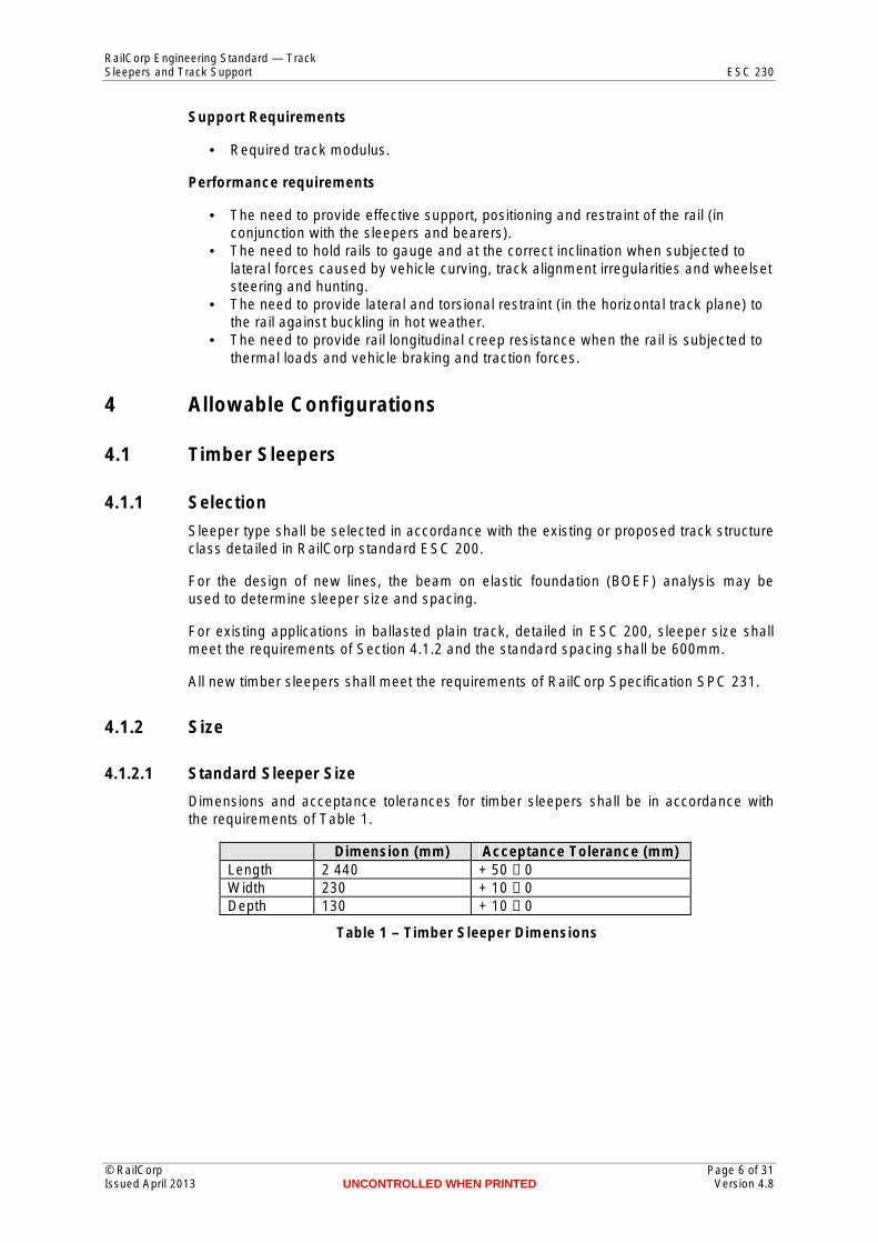
Dimensions and acceptance tolerances for timber sleepers shall be in accordance with the requirements of Table 1.
Dimension (mm) Acceptance Tolerance (mm) Length 2 440 + 50 − 0 Width 230 + 10 − 0 Depth 130 + 10 − 0
Table 1 – Timber Sleeper Dimensions
© RailCorp Page 6 of 31 Issued April 2013 UNCONTROLLED WHEN PRINTED Version 4.8
RailCorp Engineering Standard — Track Sleepers and Track Support ESC 230
4.1.2.2 Half Sleeper Size
Dimensions and acceptance tolerances for half sleepers for use in the City Tunnels shall be in accordance with the requirements of Table 2.
Dimension (mm) Acceptance Tolerance (mm) Length 800 + 50 − 0 Width 230 + 10 − 0 Depth 130 + 10 − 0 Distance from the centre line of the rail to the end of the timber in either direction
Minimum 345 NA
Distance from the end of the sleeper plate to the end of the sleeper
Minimum 90 NA
Table 2 - Timber half sleeper dimensions
4.1.3 Usage
4.1.3.1 New Timber Sleepers
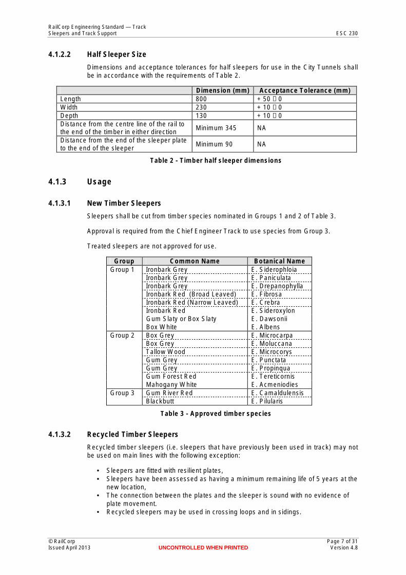
Sleepers shall be cut from timber species nominated in Groups 1 and 2 of Table 3.
Approval is required from the Chief Engineer Track to use species from Group 3.
Treated sleepers are not approved for use.
Group Common Name Botanical Name Group 1 Ironbark Grey
Ironbark Grey Ironbark Grey Ironbark Red (Broad Leaved) Ironbark Red (Narrow Leaved) Ironbark Red Gum Slaty or Box Slaty Box White
E. Siderophloia E. Paniculata E. Drepanophylla E. Fibrosa E. Crebra E. Sideroxylon E. Dawsonii E. Albens
Group 2 Box Grey Box Grey Tallow Wood Gum Grey Gum Grey Gum Forest Red Mahogany White
E. Microcarpa E. Moluccana E. Microcorys E. Punctata E. Propinqua E. Tereticornis E. Acmeniodies
Group 3 Gum River Red E. Camaldulensis Blackbutt E. Pilularis
Table 3 - Approved timber species
4.1.3.2 Recycled Timber Sleepers
Recycled timber sleepers (i.e. sleepers that have previously been used in track) may not be used on main lines with the following exception:
• Sleepers are fitted with resilient plates, • Sleepers have been assessed as having a minimum remaining life of 5 years at the
new location, • The connection between the plates and the sleeper is sound with no evidence of
plate movement. • Recycled sleepers may be used in crossing loops and in sidings.
© RailCorp Page 7 of 31 Issued April 2013 UNCONTROLLED WHEN PRINTED Version 4.8
RailCorp Engineering Standard — Track Sleepers and Track Support ESC 230
4.1.4 Spacing
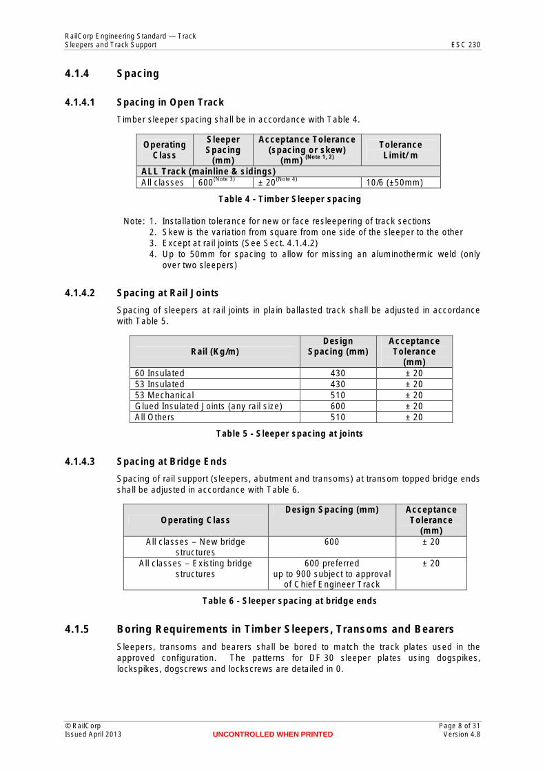
4.1.4.1 Spacing in Open Track
Timber sleeper spacing shall be in accordance with Table 4.
Operating Class
Sleeper Spacing
(mm)
Acceptance Tolerance (spacing or skew)
(mm) (Note 1, 2)
Tolerance Limit/ m
ALL Track (mainline & sidings) All classes 600(Note 3) ± 20(Note 4) 10/6 (±50mm)
Table 4 - Timber Sleeper spacing
Note: 1. Installation tolerance for new or face resleepering of track sections 2. Skew is the variation from square from one side of the sleeper to the other 3. Except at rail joints (See Sect. 4.1.4.2) 4. Up to 50mm for spacing to allow for missing an aluminothermic weld (only
over two sleepers)
4.1.4.2 Spacing at Rail Joints
Spacing of sleepers at rail joints in plain ballasted track shall be adjusted in accordance with Table 5.
Rail (Kg/m) Design
Spacing (mm) Acceptance Tolerance
(mm) 60 Insulated 430 ± 20 53 Insulated 430 ± 20 53 Mechanical 510 ± 20 Glued Insulated Joints (any rail size) 600 ± 20 All Others 510 ± 20
Table 5 - Sleeper spacing at joints
4.1.4.3 Spacing at Bridge Ends
Spacing of rail support (sleepers, abutment and transoms) at transom topped bridge ends shall be adjusted in accordance with Table 6.
Operating Class Design Spacing (mm) Acceptance
Tolerance (mm)
All classes – New bridge structures
600 ± 20
All classes – Existing bridge structures
600 preferred up to 900 subject to approval
of Chief Engineer Track
± 20
Table 6 - Sleeper spacing at bridge ends
4.1.5 Boring Requirements in Timber Sleepers, Transoms and Bearers
Sleepers, transoms and bearers shall be bored to match the track plates used in the approved configuration. The patterns for DF 30 sleeper plates using dogspikes, lockspikes, dogscrews and lockscrews are detailed in 0.
© RailCorp Page 8 of 31 Issued April 2013 UNCONTROLLED WHEN PRINTED Version 4.8
RailCorp Engineering Standard — Track Sleepers and Track Support ESC 230
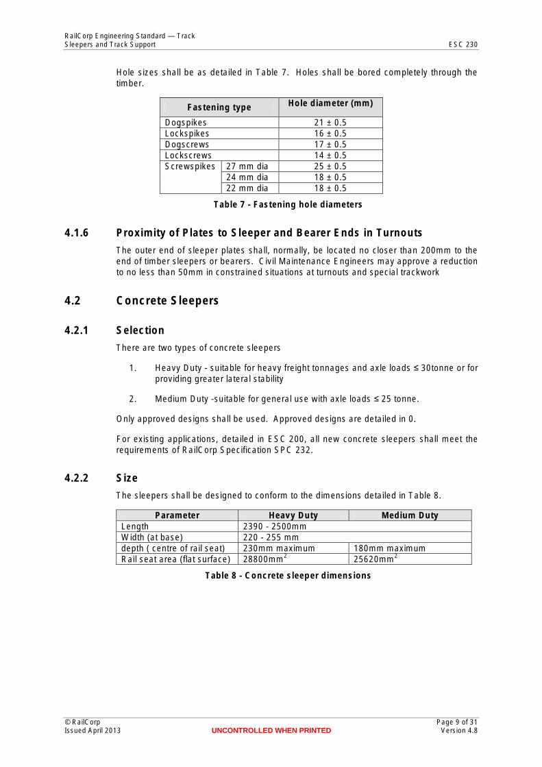
Hole sizes shall be as detailed in Table 7. Holes shall be bored completely through the timber.
Fastening type Hole diameter (mm)
Dogspikes 21 ± 0.5 Lockspikes 16 ± 0.5 Dogscrews 17 ± 0.5 Lockscrews 14 ± 0.5 Screwspikes 27 mm dia 25 ± 0.5
24 mm dia 18 ± 0.5 22 mm dia 18 ± 0.5
Table 7 - Fastening hole diameters
4.1.6 Proximity of Plates to Sleeper and Bearer Ends in Turnouts
The outer end of sleeper plates shall, normally, be located no closer than 200mm to the end of timber sleepers or bearers. Civil Maintenance Engineers may approve a reduction to no less than 50mm in constrained situations at turnouts and special trackwork
4.2 Concrete Sleepers
4.2.1 Selection
There are two types of concrete sleepers
1. Heavy Duty - suitable for heavy freight tonnages and axle loads ≤ 30tonne or for providing greater lateral stability
2. Medium Duty -suitable for general use with axle loads ≤ 25 tonne.
Only approved designs shall be used. Approved designs are detailed in 0.
For existing applications, detailed in ESC 200, all new concrete sleepers shall meet the requirements of RailCorp Specification SPC 232.
4.2.2 Size
The sleepers shall be designed to conform to the dimensions detailed in Table 8.
Parameter Heavy Duty Medium Duty Length 2390 - 2500mm Width (at base) 220 - 255 mm depth ( centre of rail seat) 230mm maximum 180mm maximum Rail seat area (flat surface) 28800mm2 25620mm2
Table 8 - Concrete sleeper dimensions
© RailCorp Page 9 of 31 Issued April 2013 UNCONTROLLED WHEN PRINTED Version 4.8
RailCorp Engineering Standard — Track Sleepers and Track Support ESC 230
4.2.3 Use
Sleeper type shall be selected in accordance with the existing or proposed track structure class detailed in RailCorp standard ESC 200.
On Mixed Passenger Freight Main Lines, the selection of heavy duty or medium duty concrete sleeper is governed by the following requirement:
• On sharp curves <400m radius where Pandrol e2003 clips are installed, heavy duty insulators shall be used for new installations and for replacement of insulators. Heavy duty insulators are not required with 'Fastclip' installations.
Where concrete sleepers are used as replacement sleepers within existing sections of concrete sleepers they shall reasonably match adjacent sleepers in dimensions and capacity.
Concrete sleepers may only be interspersed with timber sleepers where they are in accordance with a specific strategy approved by the Chief Engineer Track.
Where concrete sleepers are installed adjacent to turnouts with timber bearers, a transition zone of eight (8) timber bearers or sleepers is required between the concrete sleepers and the toe of the points.
To improve the stability of track approaching transom top bridges, where concrete sleepers are installed adjacent to transom top bridges, twenty (20) Heavy Duty concrete sleepers shall be installed.
4.2.4 Spacing
4.2.4.1 Spacing in Open Track
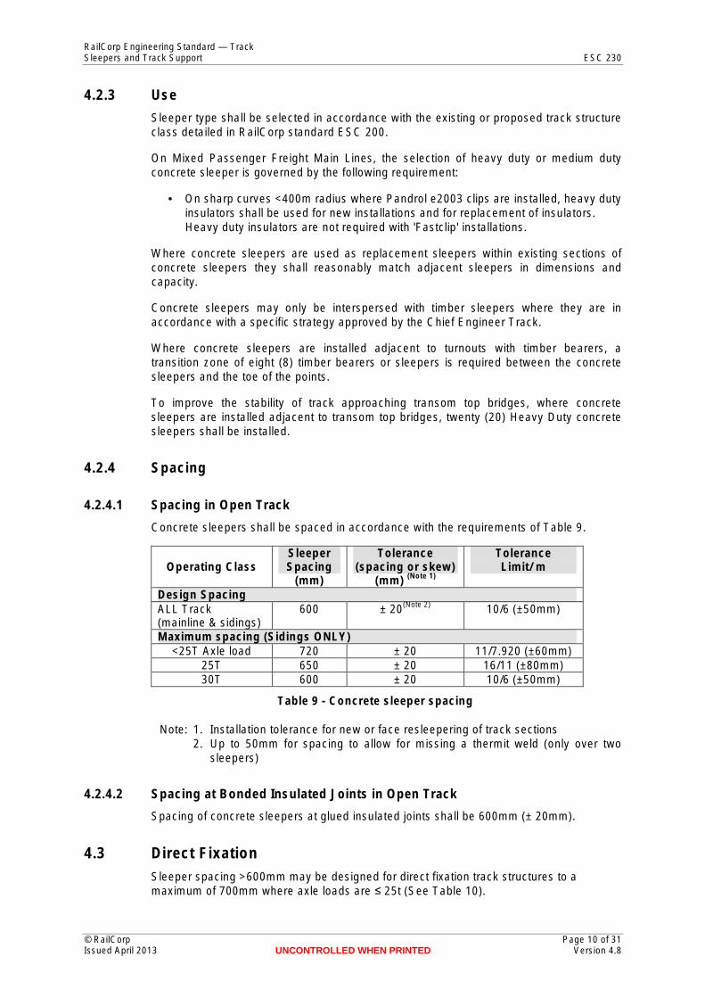
Concrete sleepers shall be spaced in accordance with the requirements of Table 9.
Sleeper Tolerance Tolerance Operating Class Spacing
(mm) (spacing or skew)
(mm) (Note 1) Limit/ m
Design Spacing ALL Track (mainline & sidings)
600 ± 20(Note 2) 10/6 (±50mm)
Maximum spacing (Sidings ONLY) <25T Axle load 720 ± 20 11/7.920 (±60mm)
25T 650 ± 20 16/11 (±80mm) 30T 600 ± 20 10/6 (±50mm)
Table 9 - Concrete sleeper spacing
Note: 1. Installation tolerance for new or face resleepering of track sections 2. Up to 50mm for spacing to allow for missing a thermit weld (only over two
sleepers)
4.2.4.2 Spacing at Bonded Insulated Joints in Open Track
Spacing of concrete sleepers at glued insulated joints shall be 600mm (± 20mm).
Sleeper spacing >600mm may be designed for direct fixation track structures to a maximum of 700mm where axle loads are ≤ 25t (See Table 10).
© RailCorp Page 10 of 31 Issued April 2013 UNCONTROLLED WHEN PRINTED Version 4.8
4.3 Direct Fixation
RailCorp Engineering Standard — Track Sleepers and Track Support ESC 230
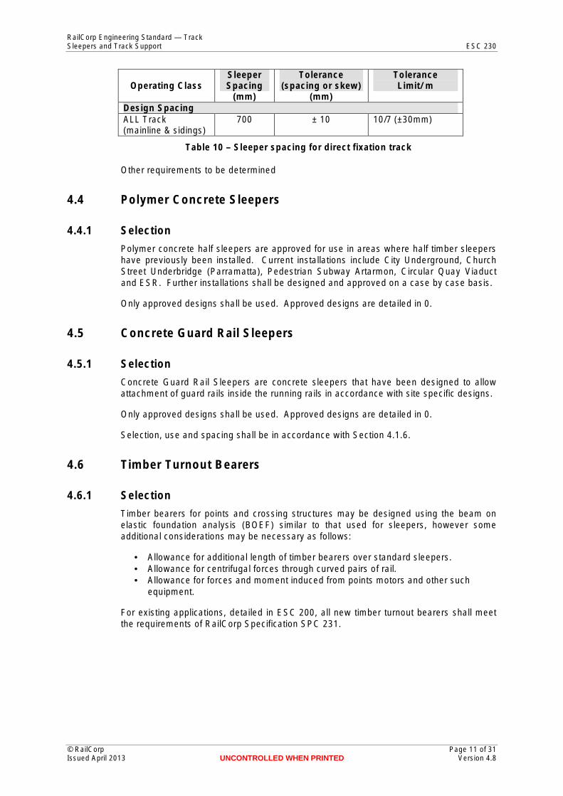
Sleeper Tolerance Tolerance Operating Class Spacing (spacing or skew) Limit/ m
(mm) (mm) Design Spacing ALL Track 700 ± 10 10/7 (±30mm) (mainline & sidings)
Table 10 – Sleeper spacing for direct fixation track
Other requirements to be determined
4.4 Polymer Concrete Sleepers
4.4.1 Selection
Polymer concrete half sleepers are approved for use in areas where half timber sleepers have previously been installed. Current installations include City Underground, Church Street Underbridge (Parramatta), Pedestrian Subway Artarmon, Circular Quay Viaduct and ESR. Further installations shall be designed and approved on a case by case basis.
Only approved designs shall be used. Approved designs are detailed in 0.
4.5 Concrete Guard Rail Sleepers
4.5.1 Selection
Concrete Guard Rail Sleepers are concrete sleepers that have been designed to allow attachment of guard rails inside the running rails in accordance with site specific designs.
Only approved designs shall be used. Approved designs are detailed in 0.
Selection, use and spacing shall be in accordance with Section 4.1.6.
4.6 Timber Turnout Bearers
4.6.1 Selection
Timber bearers for points and crossing structures may be designed using the beam on elastic foundation analysis (BOEF) similar to that used for sleepers, however some additional considerations may be necessary as follows:
• Allowance for additional length of timber bearers over standard sleepers. • Allowance for centrifugal forces through curved pairs of rail. • Allowance for forces and moment induced from points motors and other such
equipment.
For existing applications, detailed in ESC 200, all new timber turnout bearers shall meet the requirements of RailCorp Specification SPC 231.
© RailCorp Page 11 of 31 Issued April 2013 UNCONTROLLED WHEN PRINTED Version 4.8
RailCorp Engineering Standard — Track Sleepers and Track Support ESC 230
4.6.2 Timber Bearer Size
Dimensions of timber turnout bearers shall be selected as follows:
Width – 250mm Depth – 180mm for general application
200mm for bearers on which points motors will be attached. Boxed heart timber bearers are only approved for use in depths of 180mm and 200mm.
Length – The minimum length of timber bearers shall be calculated as the measurement from the “Outside” gauge face to “outside” gauge face at the point at which the bearer is to be installed + 1.0m. The length shall be rounded up to match the next available size for the selected bearer depth in Table 11.
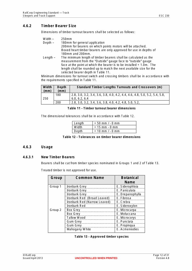
Minimum dimensions for turnout switch and crossing timbers shall be in accordance with the requirements specified in Table 11.
Width (mm)
Depth (mm)
Standard Timber Lengths Turnouts and Crossovers (m)
250 180 2.8, 3.0, 3.2, 3.4, 3.6, 3.8, 4.0, 4.2, 4.4, 4.6, 4.8, 5.0, 5.2, 5.4, 5.8,
6.0, 6.2, 6.4 200 2.8, 3.0, 3.2, 3.4, 3.6, 3.8, 4.0, 4.2, 4.8, 5.0, 5.2,
Table 11 - Timber turnout bearer dimensions
The dimensional tolerances shall be in accordance with Table 12.
Length + 50 mm / - 0 mm Width + 15 mm - 0 mm Depth + 10 mm / - 0 mm
Table 12 - Tolerances on timber bearer dimensions
4.6.3 Usage
4.6.3.1 New Timber Bearers
Bearers shall be cut from timber species nominated in Groups 1 and 2 of Table 13.
Treated timber is not approved for use.
Group Common Name Botanical Name
Group 1 Ironbark Grey Ironbark Grey Ironbark Grey Ironbark Red (Broad Leaved) Ironbark Red (Narrow Leaved) Ironbark Red
E. Siderophloia E. Paniculata E. Drepanophylla E. Fibrosa E. Crebra E. Sideroxylon
Group 2 Box Grey Box Grey Tallow Wood Gum Grey Gum Grey Mahogany White
E. Microcarpa E. Moluccana E. Microcorys E. Punctata E. Propinqua E. Acmeniodies
Table 13 - Approved timber species
© RailCorp Page 12 of 31 Issued April 2013 UNCONTROLLED WHEN PRINTED Version 4.8
RailCorp Engineering Standard — Track Sleepers and Track Support ESC 230
4.6.3.2 Recycled Timber Bearers
Recycled timber bearers (i.e. bearers that have previously been used in track) may not be used on main lines.
Recycled bearers may be used in crossing loops and in sidings.
4.6.4 Spacing
Nominal design spacing of timber turnout bearers shall be 600mm. Variation of spacing to suit turnout requirements is permitted up to a maximum of 700mm (except at mechanical joints or mechanical insulated joints where the maximum is 600mm). Spacing shall not be less than 500mm.
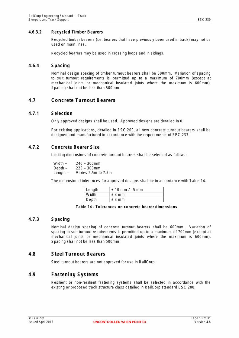
4.7 Concrete Turnout Bearers
4.7.1 Selection
Only approved designs shall be used. Approved designs are detailed in 0.
For existing applications, detailed in ESC 200, all new concrete turnout bearers shall be designed and manufactured in accordance with the requirements of SPC 233.
4.7.2 Concrete Bearer Size
Limiting dimensions of concrete turnout bearers shall be selected as follows:
Width – 240 – 300mmDepth – 220 – 300mmLength – Varies 2.5m to 7.5m
The dimensional tolerances for approved designs shall be in accordance with Table 14.
Length + 10 mm / - 5 mm Width ± 3 mm Depth ± 3 mm
Table 14 - Tolerances on concrete bearer dimensions
4.7.3 Spacing
Nominal design spacing of concrete turnout bearers shall be 600mm. Variation of spacing to suit turnout requirements is permitted up to a maximum of 700mm (except at mechanical joints or mechanical insulated joints where the maximum is 600mm). Spacing shall not be less than 500mm.
4.8 Steel Turnout Bearers Steel turnout bearers are not approved for use in RailCorp.
4.9 Fastening Systems Resilient or non-resilient fastening systems shall be selected in accordance with the existing or proposed track structure class detailed in RailCorp standard ESC 200.
© RailCorp Page 13 of 31 Issued April 2013 UNCONTROLLED WHEN PRINTED Version 4.8
RailCorp Engineering Standard — Track Sleepers and Track Support ESC 230
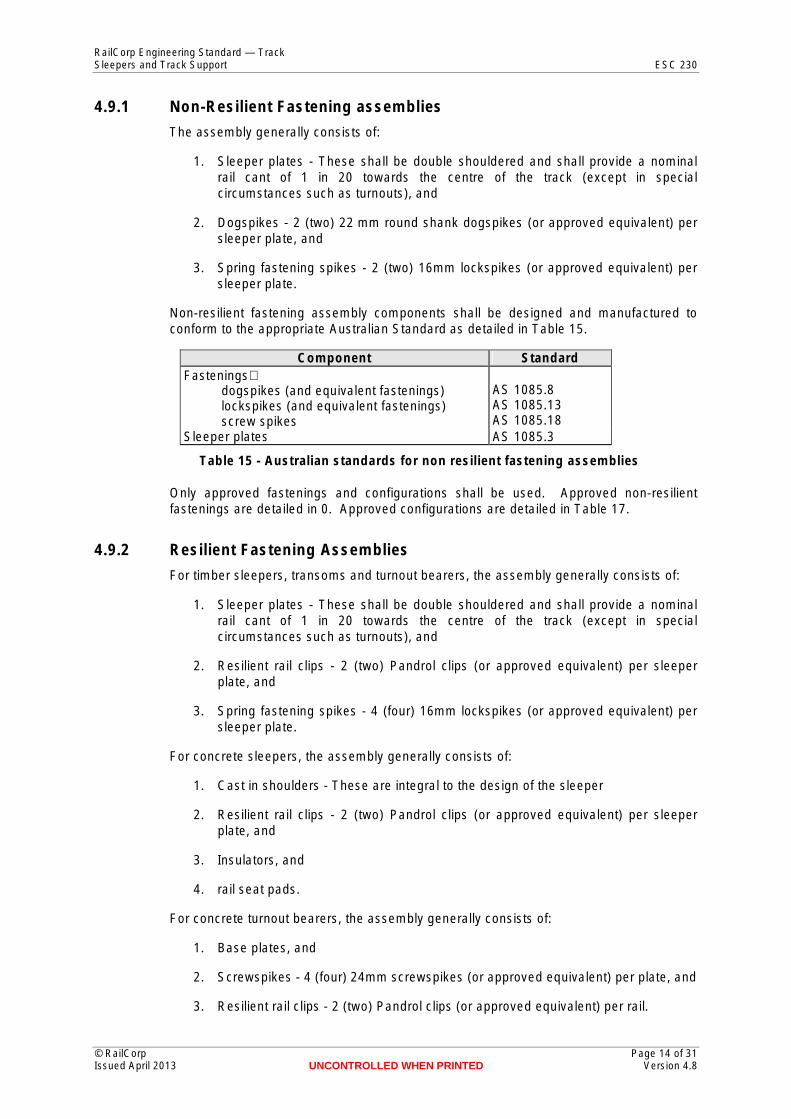
4.9.1 Non-Resilient Fastening assemblies
The assembly generally consists of:
1. Sleeper plates - These shall be double shouldered and shall provide a nominal rail cant of 1 in 20 towards the centre of the track (except in special circumstances such as turnouts), and
2. Dogspikes - 2 (two) 22 mm round shank dogspikes (or approved equivalent) per sleeper plate, and
3. Spring fastening spikes - 2 (two) 16mm lockspikes (or approved equivalent) per sleeper plate.
Non-resilient fastening assembly components shall be designed and manufactured to conform to the appropriate Australian Standard as detailed in Table 15.
Component Standard Fastenings⎯
dogspikes (and equivalent fastenings) lockspikes (and equivalent fastenings) screw spikes
Sleeper plates
AS 1085.8 AS 1085.13 AS 1085.18 AS 1085.3
Table 15 - Australian standards for non resilient fastening assemblies
Only approved fastenings and configurations shall be used. Approved non-resilient fastenings are detailed in 0. Approved configurations are detailed in Table 17.
4.9.2 Resilient Fastening Assemblies
For timber sleepers, transoms and turnout bearers, the assembly generally consists of:
1. Sleeper plates - These shall be double shouldered and shall provide a nominal rail cant of 1 in 20 towards the centre of the track (except in special circumstances such as turnouts), and
2. Resilient rail clips - 2 (two) Pandrol clips (or approved equivalent) per sleeper plate, and
3. Spring fastening spikes - 4 (four) 16mm lockspikes (or approved equivalent) per sleeper plate.
For concrete sleepers, the assembly generally consists of:
1. Cast in shoulders - These are integral to the design of the sleeper
2. Resilient rail clips - 2 (two) Pandrol clips (or approved equivalent) per sleeper plate, and
3. Insulators, and
4. rail seat pads.
For concrete turnout bearers, the assembly generally consists of:
1. Base plates, and
2. Screwspikes - 4 (four) 24mm screwspikes (or approved equivalent) per plate, and
3. Resilient rail clips - 2 (two) Pandrol clips (or approved equivalent) per rail.
© RailCorp Page 14 of 31 Issued April 2013 UNCONTROLLED WHEN PRINTED Version 4.8
RailCorp Engineering Standard — Track Sleepers and Track Support ESC 230
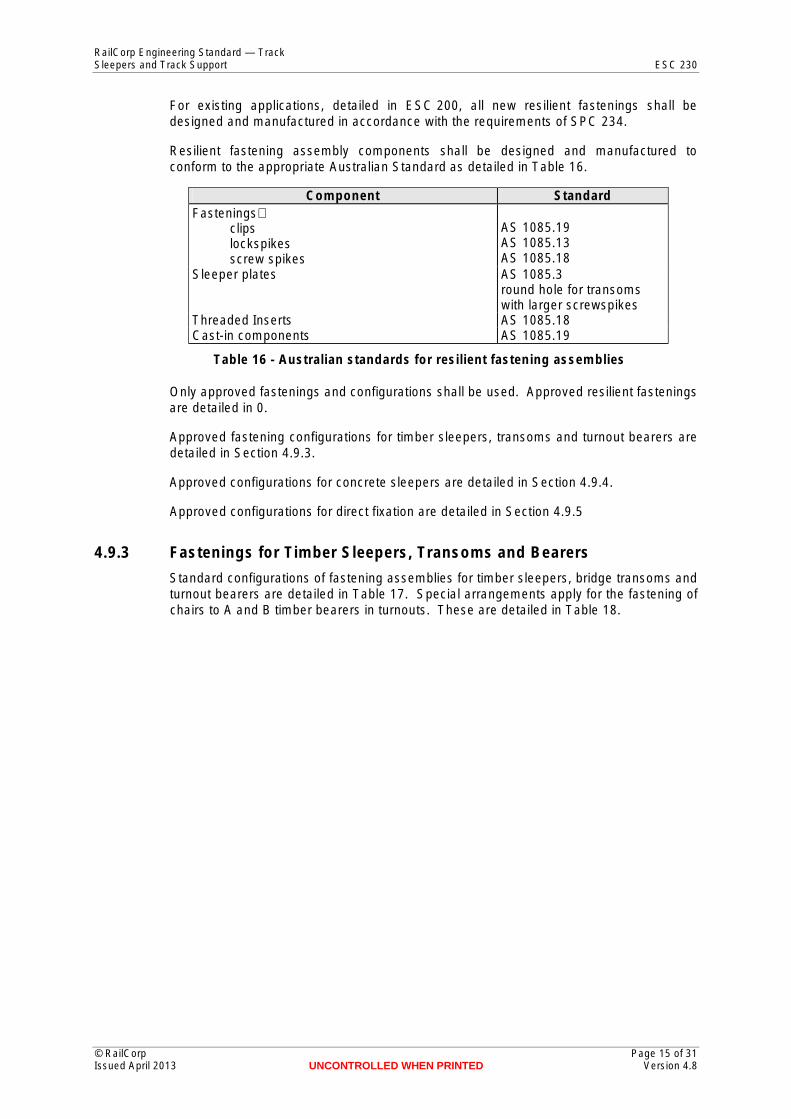
For existing applications, detailed in ESC 200, all new resilient fastenings shall be designed and manufactured in accordance with the requirements of SPC 234.
Resilient fastening assembly components shall be designed and manufactured to conform to the appropriate Australian Standard as detailed in Table 16.
Component Standard Fastenings⎯
clips AS 1085.19 lockspikes AS 1085.13 screw spikes AS 1085.18
Sleeper plates AS 1085.3 round hole for transoms with larger screwspikes
Threaded Inserts AS 1085.18 Cast-in components AS 1085.19
Table 16 - Australian standards for resilient fastening assemblies
Only approved fastenings and configurations shall be used. Approved resilient fastenings are detailed in 0.
Approved fastening configurations for timber sleepers, transoms and turnout bearers aredetailed in Section 4.9.3.
Approved configurations for concrete sleepers are detailed in Section 4.9.4.
Approved configurations for direct fixation are detailed in Section 4.9.5
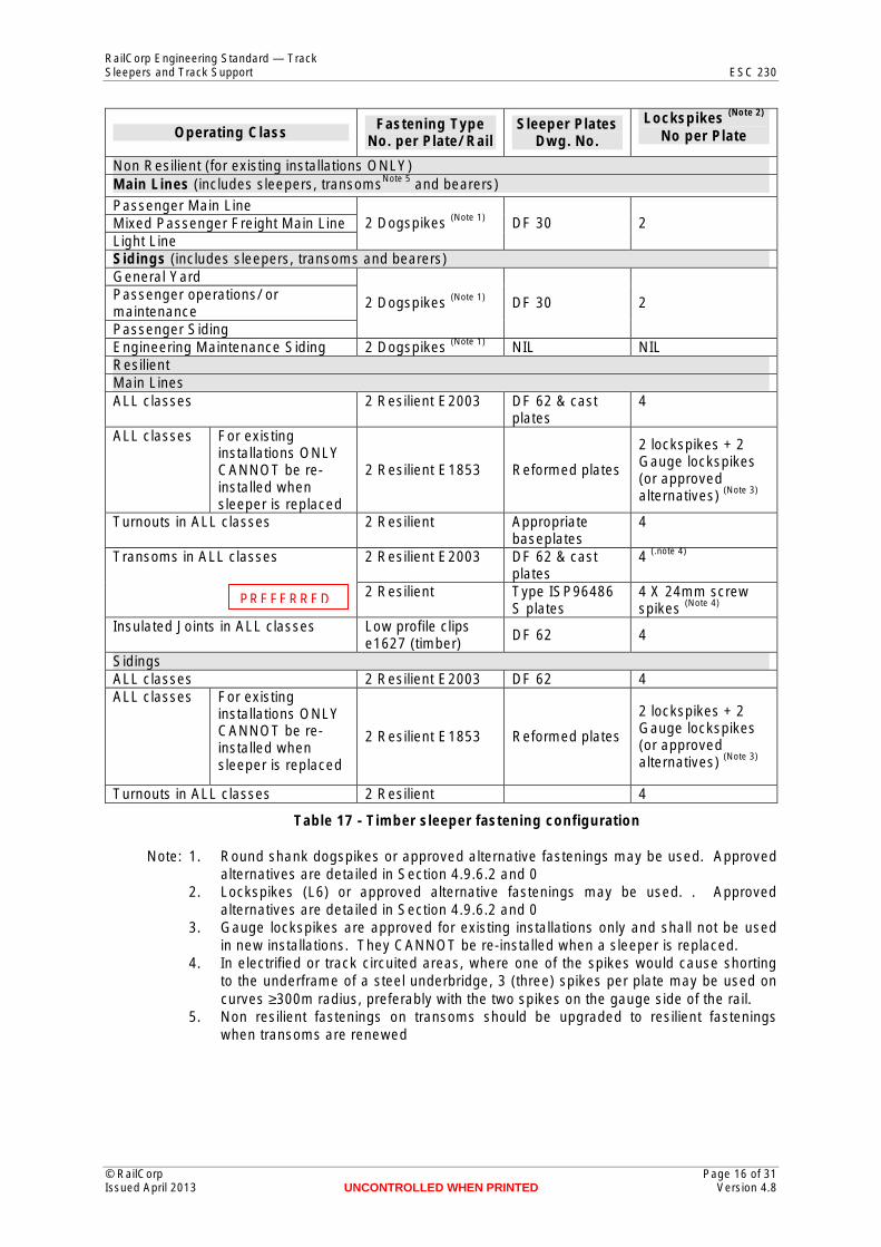
4.9.3 Fastenings for Timber Sleepers, Transoms and Bearers
Standard configurations of fastening assemblies for timber sleepers, bridge transoms and turnout bearers are detailed in Table 17. Special arrangements apply for the fastening of chairs to A and B timber bearers in turnouts. These are detailed in Table 18.
© RailCorp Page 15 of 31 Issued April 2013 UNCONTROLLED WHEN PRINTED Version 4.8
RailCorp Engineering Standard — Track Sleepers and Track Support ESC 230
(Note 2) Lockspikes Fastening Type Sleeper Plates Operating Class No per Plate No. per Plate/ Rail Dwg. No.
Non Resilient (for existing installations ONLY) Note 5 Main Lines (includes sleepers, transoms and bearers)
Passenger Main Line (Note 1) Mixed Passenger Freight Main Line 2 Dogspikes DF 30 2
Light Line Sidings (includes sleepers, transoms and bearers) General Yard Passenger operations/ or (Note 1) 2 Dogspikes DF 30 2 maintenance Passenger Siding
(Note 1) Engineering Maintenance Siding 2 Dogspikes NIL NIL Resilient Main Lines ALL classes 2 Resilient E2003 DF 62 & cast 4
plates ALL classes For existing
2 lockspikes + 2 installations ONLY Gauge lockspikes CANNOT be re 2 Resilient E1853 Reformed plates (or approved installed when alternatives) (Note 3)
sleeper is replaced Turnouts in ALL classes 2 Resilient Appropriate 4
baseplates 4 (.note 4) Transoms in ALL classes 2 Resilient E2003 DF 62 & cast
plates 2 Resilient Type ISP96486 4 X 24mm screw PREFERRED (Note 4) S plates spikes
Insulated Joints in ALL classes Low profile clips DF 62 4 e1627 (timber)
Sidings ALL classes 2 Resilient E2003 DF 62 4 ALL classes For existing
installations ONLY 2 lockspikes + 2 CANNOT be re Gauge lockspikes 2 Resilient E1853 Reformed plates installed when (or approved
alternatives) (Note 3) sleeper is replaced
Turnouts in ALL classes 2 Resilient 4
Table 17 - Timber sleeper fastening configuration
Note: 1. Round shank dogspikes or approved alternative fastenings may be used. Approved alternatives are detailed in Section 4.9.6.2 and 0
2. Lockspikes (L6) or approved alternative fastenings may be used. . Approved alternatives are detailed in Section 4.9.6.2 and 0
3. Gauge lockspikes are approved for existing installations only and shall not be used in new installations. They CANNOT be re-installed when a sleeper is replaced.
4. In electrified or track circuited areas, where one of the spikes would cause shorting to the underframe of a steel underbridge, 3 (three) spikes per plate may be used on curves ≥300m radius, preferably with the two spikes on the gauge side of the rail.
5. Non resilient fastenings on transoms should be upgraded to resilient fastenings when transoms are renewed
© RailCorp Page 16 of 31 Issued April 2013 UNCONTROLLED WHEN PRINTED Version 4.8
RailCorp Engineering Standard — Track Sleepers and Track Support ESC 230
A & B Timber Bearer Fastening Type New Installations 60kg/m steelwork Screwspikes 53kg/m steelwork Holding down bolts or approved equivalent swage fastenings For Repair/ Replacement 60kg/m steelwork If the screwpikes are no longer able to provide adequate grip
or if timber quality is suspect use holding down bolts or approved equivalent swage fastenings
53kg/m steelwork Holding down bolts or approved equivalent swage fastenings
Table 18 - A & B Timber Bearer fastening configuration
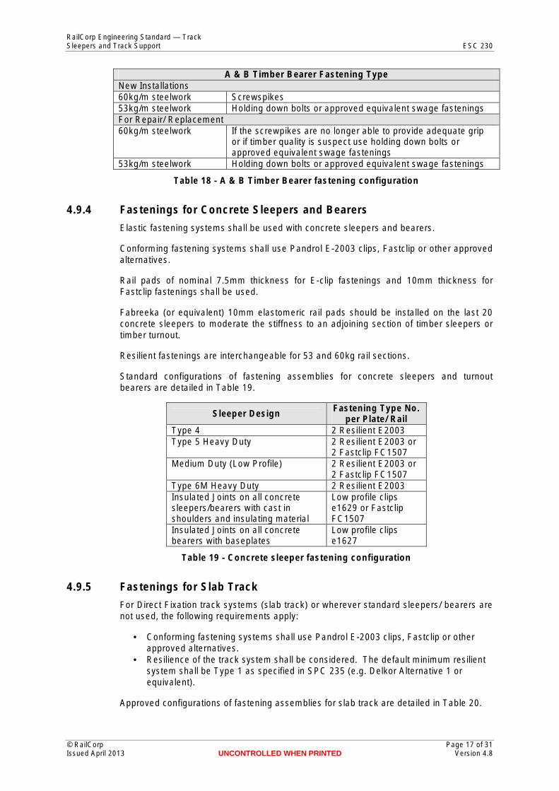
4.9.4 Fastenings for Concrete Sleepers and Bearers
Elastic fastening systems shall be used with concrete sleepers and bearers.
Conforming fastening systems shall use Pandrol E-2003 clips, Fastclip or other approved alternatives.
Rail pads of nominal 7.5mm thickness for E-clip fastenings and 10mm thickness for Fastclip fastenings shall be used.
Fabreeka (or equivalent) 10mm elastomeric rail pads should be installed on the last 20 concrete sleepers to moderate the stiffness to an adjoining section of timber sleepers or timber turnout.
Resilient fastenings are interchangeable for 53 and 60kg rail sections.
Standard configurations of fastening assemblies for concrete sleepers and turnout bearers are detailed in Table 19.
Sleeper Design Fastening Type No. per Plate/ Rail
Type 4 2 Resilient E2003 Type 5 Heavy Duty 2 Resilient E2003 or
2 Fastclip FC1507 Medium Duty (Low Profile) 2 Resilient E2003 or
2 Fastclip FC1507 Type 6M Heavy Duty 2 Resilient E2003 Insulated Joints on all concrete sleepers/bearers with cast in shoulders and insulating material
Low profile clips e1629 or Fastclip FC1507
Insulated Joints on all concrete bearers with baseplates
Low profile clips e1627
Table 19 - Concrete sleeper fastening configuration
4.9.5 Fastenings for Slab Track
For Direct Fixation track systems (slab track) or wherever standard sleepers/ bearers are not used, the following requirements apply:
• Conforming fastening systems shall use Pandrol E-2003 clips, Fastclip or other approved alternatives.
• Resilience of the track system shall be considered. The default minimum resilient system shall be Type 1 as specified in SPC 235 (e.g. Delkor Alternative 1 or equivalent).
Approved configurations of fastening assemblies for slab track are detailed in Table 20.
© RailCorp Page 17 of 31 Issued April 2013 UNCONTROLLED WHEN PRINTED Version 4.8
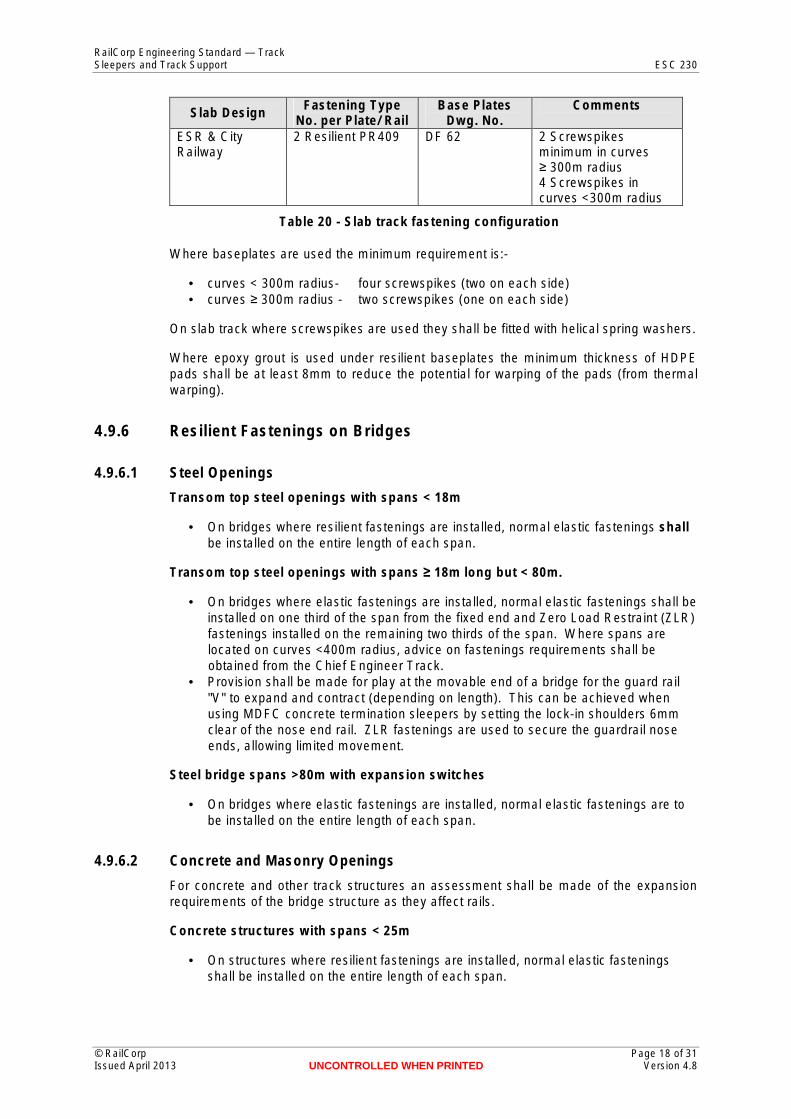
RailCorp Engineering Standard — Track Sleepers and Track Support ESC 230
Slab Design Fastening Type No. per Plate/ Rail
Base Plates Dwg. No.
Comments
ESR & City Railway
2 Resilient PR409 DF 62 2 Screwspikes minimum in curves ≥ 300m radius 4 Screwspikes in curves <300m radius
Table 20 - Slab track fastening configuration
Where baseplates are used the minimum requirement is:
• curves < 300m radius- four screwspikes (two on each side) • curves ≥ 300m radius - two screwspikes (one on each side)
On slab track where screwspikes are used they shall be fitted with helical spring washers.
Where epoxy grout is used under resilient baseplates the minimum thickness of HDPE pads shall be at least 8mm to reduce the potential for warping of the pads (from thermal warping).
4.9.6 Resilient Fastenings on Bridges
4.9.6.1 Steel Openings
Transom top steel openings with spans < 18m
• On bridges where resilient fastenings are installed, normal elastic fastenings shall be installed on the entire length of each span.
Transom top steel openings with spans ≥ 18m long but < 80m.
• On bridges where elastic fastenings are installed, normal elastic fastenings shall be installed on one third of the span from the fixed end and Zero Load Restraint (ZLR) fastenings installed on the remaining two thirds of the span. Where spans are located on curves <400m radius, advice on fastenings requirements shall be obtained from the Chief Engineer Track.
• Provision shall be made for play at the movable end of a bridge for the guard rail "V" to expand and contract (depending on length). This can be achieved when using MDFC concrete termination sleepers by setting the lock-in shoulders 6mm clear of the nose end rail. ZLR fastenings are used to secure the guardrail nose ends, allowing limited movement.
Steel bridge spans >80m with expansion switches
• On bridges where elastic fastenings are installed, normal elastic fastenings are to be installed on the entire length of each span.
4.9.6.2 Concrete and Masonry Openings
For concrete and other track structures an assessment shall be made of the expansion requirements of the bridge structure as they affect rails.
Concrete structures with spans < 25m
• On structures where resilient fastenings are installed, normal elastic fastenings shall be installed on the entire length of each span.
© RailCorp Page 18 of 31 Issued April 2013 UNCONTROLLED WHEN PRINTED Version 4.8
RailCorp Engineering Standard — Track Sleepers and Track Support ESC 230
Concrete structures with spans ≥ 25m
• An assessment shall be made of the expansion needs and appropriate ZLR fastenings installed. Proposals shall be submitted to the Chief Engineer Track for approval.
Note: whilst the expansion of concrete is similar to that of steel there is a difference in the temperature variation expected in concrete. For steel the minimum span to be considered is 18m.
4.9.6.3 Ballast Top Openings
Requirements for expansion of the rails and the ballast must be considered if the span is more than 40m in length otherwise standard fastening systems can be applied.
4.9.7 Alternative and Special Configurations
4.9.7.1 Pandrol Clips at Insulated Joints
Special low profile Pandrol clips shall be used at insulated joints in 53 & 60Kg rails to eliminate contact between clips and fishbolts.
The clips are:
• For concrete sleepers and bearers - ‘e’1629 • For timber sleepers and bearers - ‘e’1627
Clearances are compromised with the low profile clips in timber bearers with type PZ 147 and type 1 baseplates. Any clips that may become foul may be removed as long as sufficient fastenings remain in place to retain gauge security.
4.9.7.2 Approved Alternatives to Dogspikes and Lockspikes
The Pandrol (AJAX) Dogscrew and Lockscrew are approved alternatives to dogspikes and lockspikes respectively. They may be installed with the approval of the Civil Maintenance Engineer.
The Dogscrew consists of a 19mm threaded shank with a 22mm shoulder below the flange. On top of the flange is a 6-lob head designed to fit an E24 drive socket.
The Lockscrew consists of a 16mm threaded shank with a flange and 6 lob head, the same as the Dogscrew. There are two types of Lockscrew:
Small flange – for general use
Large flange – for use with the automatic magnet pickup machine used by production gangs. This type cannot be used on rolled Pandrol plates because of the flange interferes with the rolled shoulder and does not sit flush on the plate.
4.9.7.3 Resilient Baseplate Assemblies
Resilient baseplate assemblies may be used as an alternative to standard base plates on timber sleepers, transoms and bearers, concrete sleepers and bearers and for direct fixation track applications in the following applications:
• bridges where noise and / or vibration reduction is required, • ballasted track where noise and / or vibration reduction is required, • direct fixation track where noise and / or vibration reduction is required, and
© RailCorp Page 19 of 31 Issued April 2013 UNCONTROLLED WHEN PRINTED Version 4.8
RailCorp Engineering Standard — Track Sleepers and Track Support ESC 230
• at interfaces between ballast and non-ballasted track where graded changes in track stiffness are required
Only approved designs shall be used. Approved designs are detailed in 0.
All new Resilient Baseplate assemblies shall be designed and manufactured in accordance with the requirements of RailCorp specification SPC 235.
4.9.7.4 Zero Load Restraint (ZLR) Assemblies
Zero Load Restraint assemblies allow longitudinal rail movement whilst retaining gauge and limiting upward movement of the rail. They shall be used in accordance with Section 4.9.6. Approved designs are listed in Table 21 and detailed in 0.
When used in conjunction with resilient baseplate assemblies, special configurations are required to fit the dimensional restrictions of the baseplate.
Configuration type Assembly Components Standard baseplates (with lockspikes or screwspikes)
Pandrol PMP 41027 for AS60kg rail
ZLR Cap 41027 Clip e2079
Alternative 1 resilient baseplates
Pandrol 12730 for AS60kg rail
ZLR Cap 12731 Clip e2079 Insulator IN55088 5 mm Rail Pad RP-65026
"Delkor Egg" resilient baseplates
Table 21 - Zero Load Restraint assemblies
5 Prohibited Configurations The following configurations are not permitted for permanent works on RailCorp trackwork:
• Steel sleepers • Non-elastic fastening systems with 60kg/m rail • Non-elastic fastening systems with concrete sleepers • Elastic and non-elastic fastenings on the same sleeper • Elastic fastenings on more than 1 in 3 sleepers in JWR track
6 Mixed Configurations There are some limitations and special requirements when configurations are mixed. They are applicable to existing track ONLY.
• Concrete sleepers may be interspersed with timber sleepers in accordance with the following guidelines. Interspersing:
– shall be part of a line strategy, not random, – may only be used with Medium Duty sleepers, and on line sections where
medium duty sleepers may be used, – shall lead eventually to 100% concrete, – shall achieve the minimum ballast cleanliness standard, – may be installed to a standard pattern of 1:2, 1:3 or 1:4 but with variation of one
sleeper position permitted to suit local conditions, – whole curves shall be resleepered and reasonable lengths of tangent track
should be done to a consistent pattern, – is not suitable for jointed track beyond the limits detailed in ESC 220 for
standard welded track,
© RailCorp Page 20 of 31 Issued April 2013 UNCONTROLLED WHEN PRINTED Version 4.8
RailCorp Engineering Standard — Track Sleepers and Track Support ESC 230
– may be used in patterns of 1:3 and 1:4 in poor ballast conditions, but more than this may only be used in ballast of good quality.
• Timber sleepers with elastic fastenings may only be interspersed with timber sleepers with non elastic fastenings in CWR track where they are in accordance with a specific strategy and provided a consistent tie pattern is maintained (eg 1 in 2, 1 in 3 etc).
• Timber sleepers with elastic fastenings shall NOT be interspersed with timber sleepers with non elastic fastenings in LWR where this would result in them being more frequent than 1 in 3. A consistent tie pattern shall to be maintained.
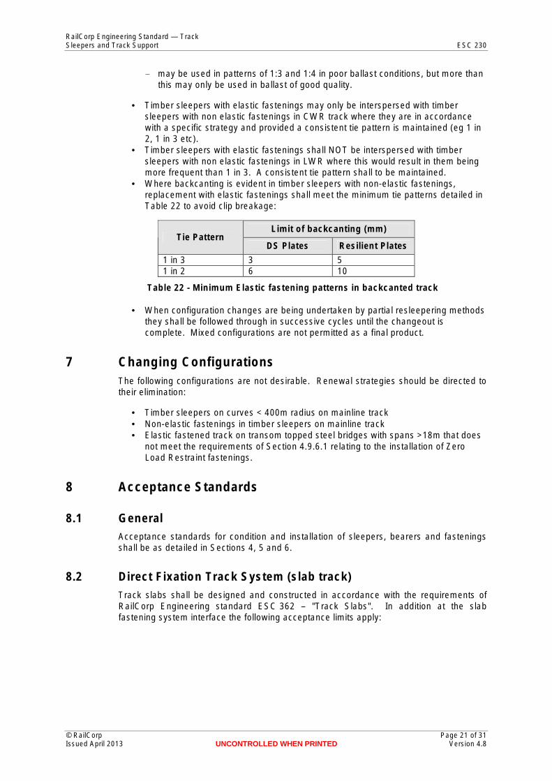
• Where backcanting is evident in timber sleepers with non-elastic fastenings, replacement with elastic fastenings shall meet the minimum tie patterns detailed in Table 22 to avoid clip breakage:
Tie Pattern Limit of backcanting (mm)
DS Plates Resilient Plates
1 in 3 3 5 1 in 2 6 10
Table 22 - Minimum Elastic fastening patterns in backcanted track
• When configuration changes are being undertaken by partial resleepering methods they shall be followed through in successive cycles until the changeout is complete. Mixed configurations are not permitted as a final product.
7 Changing Configurations The following configurations are not desirable. Renewal strategies should be directed to their elimination:
• Timber sleepers on curves < 400m radius on mainline track • Non-elastic fastenings in timber sleepers on mainline track • Elastic fastened track on transom topped steel bridges with spans >18m that does
not meet the requirements of Section 4.9.6.1 relating to the installation of Zero Load Restraint fastenings.
8 Acceptance Standards
8.1 General Acceptance standards for condition and installation of sleepers, bearers and fastenings shall be as detailed in Sections 4, 5 and 6.
8.2 Direct Fixation Track System (slab track) Track slabs shall be designed and constructed in accordance with the requirements of RailCorp Engineering standard ESC 362 – "Track Slabs". In addition at the slab fastening system interface the following acceptance limits apply:
© RailCorp Page 21 of 31 Issued April 2013 UNCONTROLLED WHEN PRINTED Version 4.8
RailCorp Engineering Standard — Track Sleepers and Track Support ESC 230
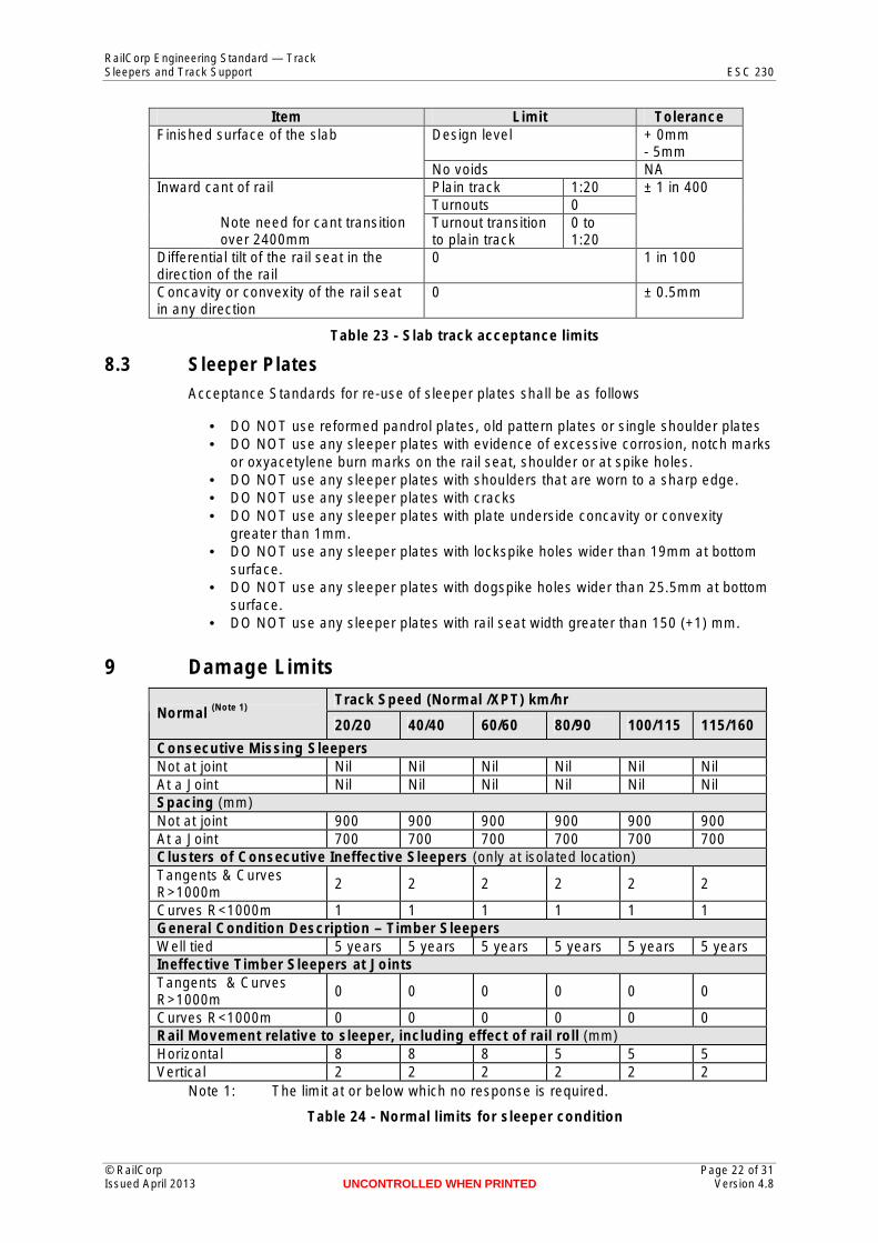
Item Limit Tolerance Finished surface of the slab Design level + 0mm
- 5mm No voids NA
Inward cant of rail Plain track 1:20 ± 1 in 400 Turnouts 0
Note need for cant transition over 2400mm
Turnout transition to plain track
0 to 1:20
Differential tilt of the rail seat in the direction of the rail
0 1 in 100
Concavity or convexity of the rail seat in any direction
0 ± 0.5mm
Table 23 - Slab track acceptance limits
8.3 Sleeper Plates Acceptance Standards for re-use of sleeper plates shall be as follows
• DO NOT use reformed pandrol plates, old pattern plates or single shoulder plates • DO NOT use any sleeper plates with evidence of excessive corrosion, notch marks
or oxyacetylene burn marks on the rail seat, shoulder or at spike holes. • DO NOT use any sleeper plates with shoulders that are worn to a sharp edge. • DO NOT use any sleeper plates with cracks • DO NOT use any sleeper plates with plate underside concavity or convexity
greater than 1mm. • DO NOT use any sleeper plates with lockspike holes wider than 19mm at bottom
surface. • DO NOT use any sleeper plates with dogspike holes wider than 25.5mm at bottom
surface. • DO NOT use any sleeper plates with rail seat width greater than 150 (+1) mm.
9 Damage Limits
Normal (Note 1) Track Speed (Normal /XPT) km/hr
20/20 40/40 60/60 80/90 100/115 115/160
Consecutive Missing Sleepers Not at joint Nil Nil Nil Nil Nil Nil At a Joint Nil Nil Nil Nil Nil Nil Spacing (mm) Not at joint 900 900 900 900 900 900 At a Joint 700 700 700 700 700 700 Clusters of Consecutive Ineffective Sleepers (only at isolated location) Tangents & Curves R>1000m
2 2 2 2 2 2
Curves R<1000m 1 1 1 1 1 1 General Condition Description – Timber Sleepers Well tied 5 years 5 years 5 years 5 years 5 years 5 years Ineffective Timber Sleepers at Joints Tangents & Curves R>1000m
0 0 0 0 0 0
Curves R<1000m 0 0 0 0 0 0 Rail Movement relative to sleeper, including effect of rail roll (mm) Horizontal 8 8 8 5 5 5 Vertical 2 2 2 2 2 2
Note 1: The limit at or below which no response is required.
Table 24 - Normal limits for sleeper condition
© RailCorp Page 22 of 31 Issued April 2013 UNCONTROLLED WHEN PRINTED Version 4.8
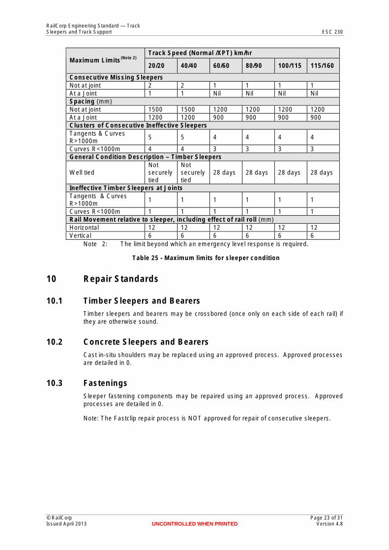
RailCorp Engineering Standard — Track Sleepers and Track Support ESC 230
Maximum Limits(Note 2) Track Speed (Normal /XPT) km/hr
20/20 40/40 60/60 80/90 100/115 115/160
Consecutive Missing Sleepers Not at joint 2 2 1 1 1 1 At a Joint 1 1 Nil Nil Nil Nil Spacing (mm) Not at joint 1500 1500 1200 1200 1200 1200 At a Joint 1200 1200 900 900 900 900 Clusters of Consecutive Ineffective Sleepers Tangents & Curves R>1000m
5 5 4 4 4 4
Curves R<1000m 4 4 3 3 3 3 General Condition Description – Timber Sleepers
Well tied Not securely tied
Not securely tied
28 days 28 days 28 days 28 days
Ineffective Timber Sleepers at Joints Tangents & Curves R>1000m
1 1 1 1 1 1
Curves R<1000m 1 1 1 1 1 1 Rail Movement relative to sleeper, including effect of rail roll (mm) Horizontal 12 12 12 12 12 12 Vertical 6 6 6 6 6 6
Note 2: The limit beyond which an emergency level response is required.
Table 25 - Maximum limits for sleeper condition
10 Repair Standards
10.1 Timber Sleepers and Bearers Timber sleepers and bearers may be crossbored (once only on each side of each rail) if they are otherwise sound.
10.2 Concrete Sleepers and Bearers Cast in-situ shoulders may be replaced using an approved process. Approved processes are detailed in 0.
10.3 Fastenings Sleeper fastening components may be repaired using an approved process. Approved processes are detailed in 0.
Note: The Fastclip repair process is NOT approved for repair of consecutive sleepers.
© RailCorp Page 23 of 31 Issued April 2013 UNCONTROLLED WHEN PRINTED Version 4.8
RailCorp Engineering Standard — Track Sleepers and Track Support ESC 230
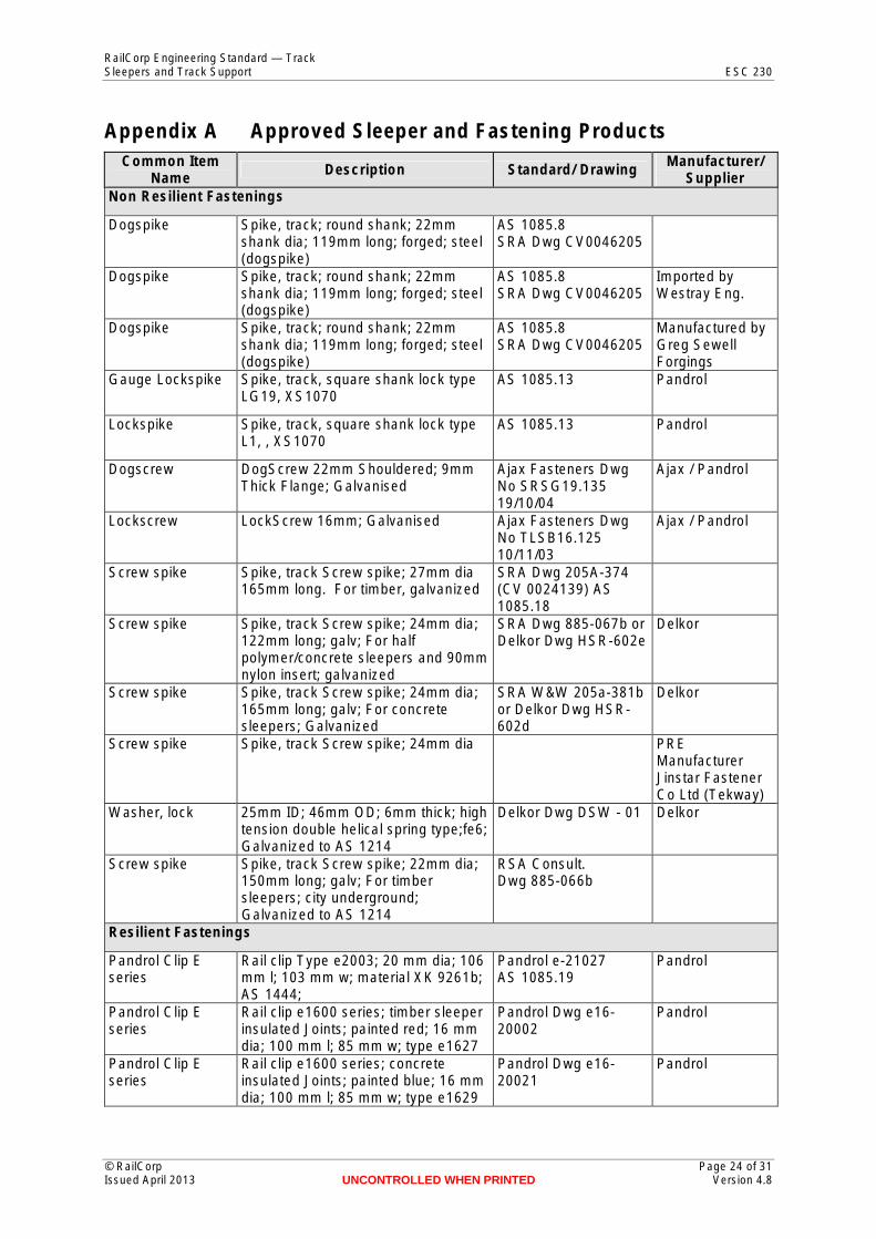
Appendix A Approved Sleeper and Fastening ProductsCommon Item
Name Description Standard/ Drawing Manufacturer/ Supplier
Non Resilient Fastenings
Dogspike Spike, track; round shank; 22mm shank dia; 119mm long; forged; steel (dogspike)
AS 1085.8 SRA Dwg CV0046205
Dogspike Spike, track; round shank; 22mm shank dia; 119mm long; forged; steel (dogspike)
AS 1085.8 SRA Dwg CV0046205
Imported by Westray Eng.
Dogspike Spike, track; round shank; 22mm shank dia; 119mm long; forged; steel (dogspike)
AS 1085.8 SRA Dwg CV0046205
Manufactured by Greg Sewell Forgings
Gauge Lockspike Spike, track, square shank lock type LG19, XS1070
AS 1085.13 Pandrol
Lockspike Spike, track, square shank lock type L1, , XS1070
AS 1085.13 Pandrol
Dogscrew DogScrew 22mm Shouldered; 9mm Thick Flange; Galvanised
Ajax Fasteners Dwg No SRSG19.135 19/10/04
Ajax / Pandrol
Lockscrew LockScrew 16mm; Galvanised Ajax Fasteners Dwg No TLSB16.125 10/11/03
Ajax / Pandrol
Screw spike Spike, track Screw spike; 27mm dia 165mm long. For timber, galvanized
SRA Dwg 205A-374 (CV 0024139) AS 1085.18
Screw spike Spike, track Screw spike; 24mm dia; 122mm long; galv; For half polymer/concrete sleepers and 90mm nylon insert; galvanized
SRA Dwg 885-067b or Delkor Dwg HSR-602e
Delkor
Screw spike Spike, track Screw spike; 24mm dia; 165mm long; galv; For concrete sleepers; Galvanized
SRA W&W 205a-381b or Delkor Dwg HSR602d
Delkor
Screw spike Spike, track Screw spike; 24mm dia PRE Manufacturer Jinstar Fastener Co Ltd (Tekway)
Washer, lock 25mm ID; 46mm OD; 6mm thick; high tension double helical spring type;fe6; Galvanized to AS 1214
Delkor Dwg DSW - 01 Delkor
Screw spike Spike, track Screw spike; 22mm dia; 150mm long; galv; For timber sleepers; city underground; Galvanized to AS 1214
RSA Consult. Dwg 885-066b
Resilient Fastenings
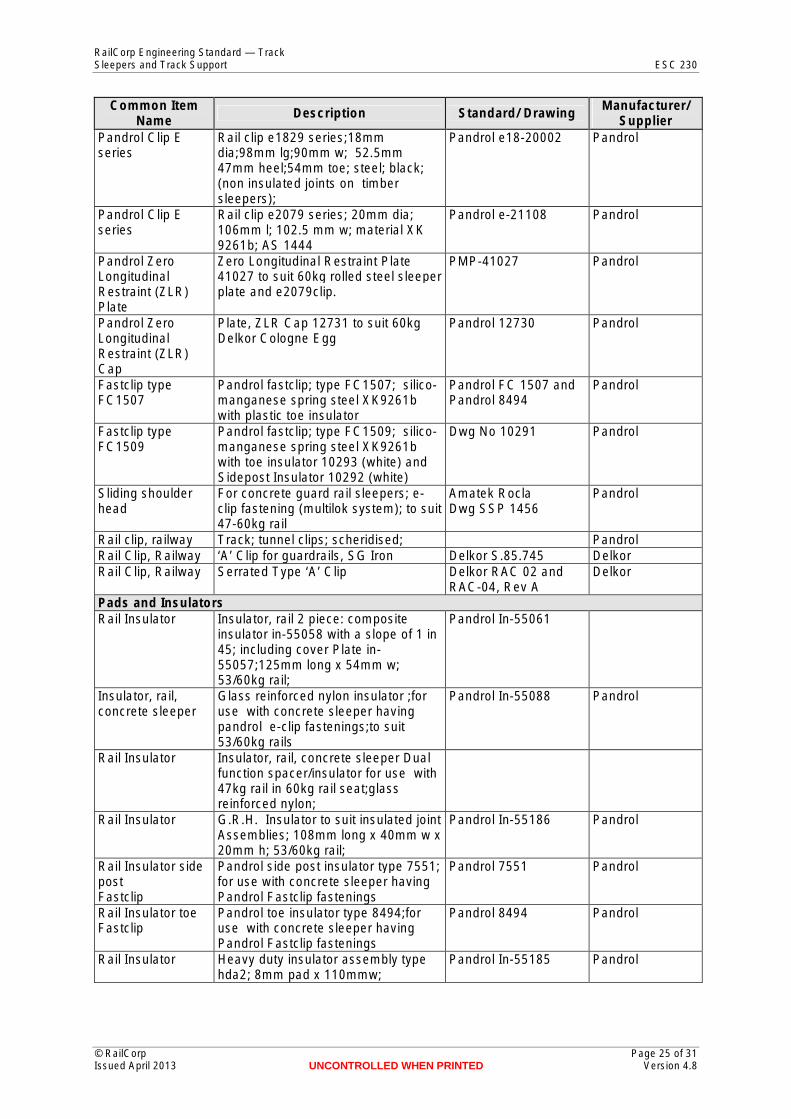
Pandrol Clip E series
Rail clip Type e2003; 20 mm dia; 106 mm l; 103 mm w; material XK 9261b; AS 1444;
Pandrol e-21027 AS 1085.19
Pandrol
Pandrol Clip E series
Rail clip e1600 series; timber sleeper insulated Joints; painted red; 16 mm dia; 100 mm l; 85 mm w; type e1627
Pandrol Dwg e1620002
Pandrol
Pandrol Clip E series
Rail clip e1600 series; concrete insulated Joints; painted blue; 16 mm dia; 100 mm l; 85 mm w; type e1629
Pandrol Dwg e1620021
Pandrol
© RailCorp Page 24 of 31 Issued April 2013 UNCONTROLLED WHEN PRINTED Version 4.8
RailCorp Engineering Standard — Track Sleepers and Track Support ESC 230
Common Item Name Description Standard/ Drawing Manufacturer/
Supplier Pandrol Clip E series
Rail clip e1829 series;18mm dia;98mm lg;90mm w; 52.5mm 47mm heel;54mm toe; steel; black; (non insulated joints on timber sleepers);
Pandrol e18-20002 Pandrol
Pandrol Clip E series
Rail clip e2079 series; 20mm dia; 106mm l; 102.5 mm w; material XK 9261b; AS 1444
Pandrol e-21108 Pandrol
Pandrol Zero Longitudinal Restraint (ZLR) Plate
Zero Longitudinal Restraint Plate 41027 to suit 60kg rolled steel sleeper plate and e2079clip.
PMP-41027 Pandrol
Pandrol Zero Longitudinal Restraint (ZLR) Cap
Plate, ZLR Cap 12731 to suit 60kg Delkor Cologne Egg
Pandrol 12730 Pandrol
Fastclip type FC1507
Pandrol fastclip; type FC1507; silicomanganese spring steel XK9261b with plastic toe insulator
Pandrol FC 1507 and Pandrol 8494
Pandrol
Fastclip type FC1509
Pandrol fastclip; type FC1509; silicomanganese spring steel XK9261b with toe insulator 10293 (white) and Sidepost Insulator 10292 (white)
Dwg No 10291 Pandrol
Sliding shoulder head
For concrete guard rail sleepers; e-clip fastening (multilok system); to suit 47-60kg rail
Amatek Rocla Dwg SSP 1456
Pandrol
Rail clip, railway Track; tunnel clips; scheridised; Pandrol Rail Clip, Railway ‘A’ Clip for guardrails, SG Iron Delkor S.85.745 Delkor Rail Clip, Railway Serrated Type ‘A’ Clip Delkor RAC 02 and
RAC-04, Rev A Delkor
Pads and Insulators Rail Insulator Insulator, rail 2 piece: composite
insulator in-55058 with a slope of 1 in 45; including cover Plate in55057;125mm long x 54mm w; 53/60kg rail;
Pandrol In-55061
Insulator, rail, concrete sleeper
Glass reinforced nylon insulator ;for use with concrete sleeper having pandrol e-clip fastenings;to suit 53/60kg rails
Pandrol In-55088 Pandrol
Rail Insulator Insulator, rail, concrete sleeper Dual function spacer/insulator for use with 47kg rail in 60kg rail seat;glass reinforced nylon;
Rail Insulator G.R.H. Insulator to suit insulated joint Assemblies; 108mm long x 40mm w x 20mm h; 53/60kg rail;
Pandrol In-55186 Pandrol
Rail Insulator side post Fastclip
Pandrol side post insulator type 7551; for use with concrete sleeper having Pandrol Fastclip fastenings
Pandrol 7551 Pandrol
Rail Insulator toe Fastclip
Pandrol toe insulator type 8494;for use with concrete sleeper having Pandrol Fastclip fastenings
Pandrol 8494 Pandrol
Rail Insulator Heavy duty insulator assembly type hda2; 8mm pad x 110mmw;
Pandrol In-55185 Pandrol
© RailCorp Page 25 of 31 Issued April 2013 UNCONTROLLED WHEN PRINTED Version 4.8
RailCorp Engineering Standard — Track Sleepers and Track Support ESC 230
Common Item Name Description Standard/ Drawing Manufacturer/
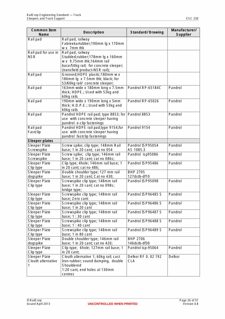
Supplier Rail pad Rail pad, railway
Fabreeka/rubber;190mm lg x 170mm w x 7mm thk
Rail pad for use in NSR
Rail pad, railway Studded;rubber;178mm lg x 160mm w x 9.75mm thk;164mm rail base/50kg rail; for concrete sleeper; (transfield product-NSR rail);
Rail pad Grooved;HDPE plastic;180mm w x 186mm lg x 7.5mm thk; black; for 53/60kg rail/ concrete sleeper;
Rail pad 163mm wide x 180mm long x 7.5mm thick; HDPE.; Used with 53kg and 60kg rails
Pandrol RP-65184C Pandrol
Rail pad 190mm wide x 190mm long x 5mm thick; H.D.P.E.; Used with 53kg and 60kg rails
Pandrol RP-65026 Pandrol
Rail pad Pandrol HDPE rail pad; type 8853; for use with concrete sleeper having pandrol e-clip fastenings
Pandrol 8853 Pandrol
Rail pad Fastclip
Pandrol HDPE rail pad;type 9154;for use with concrete sleeper having pandrol fastclip fastenings
Pandrol 9154 Pandrol
Sleeper plates Sleeper Plate Screwspike
Screw spike; clip type; 148mm Rail base; 1 in 20 cant; cat no 054
Pandrol ISP95054 AS 1085.3
Pandrol
Sleeper Plate Screwspike
Screw spike; clip type; 146mm rail base; 1 in 20 cant; cat no 086s;
Pandrol isp95086 Pandrol
Sleeper Plate Clip type
Clip type; 4hole; 146mm rail base; 1 in 20 cant; cat no 486;
Pandrol ISP95486 Pandrol
Sleeper Plate dogspike
Double shoulder type; 127 mm rail base; 1 in 20 cant; Cat no 430;
BHP 2705 127dstb-df10
Sleeper Plate Clip type
Screwspike clip type; 148mm rail base; 1 in 20 cant; cat no 098s; bridge type;
Pandrol ISP95098 Pandrol
Sleeper Plate Clip type
Screwspike clip type; 148mm rail base; Zero cant
Pandrol ISP96485 S Pandrol
Sleeper Plate Clip type
Screwspike clip type; 148mm rail base; 1 in 20 cant
Pandrol ISP96486 S Pandrol
Sleeper Plate Clip type
Screwspike clip type; 148mm rail base; 1 : 30 cant
Pandrol ISP96487 S Pandrol
Sleeper Plate Clip type
Screwspike clip type; 148mm rail base; 1 : 40 cant
Pandrol ISP96488 S Pandrol
Sleeper Plate Clip type
Screwspike clip type; 148mm rail base; 1 in 80 cant
Pandrol ISP96489 S Pandrol
Sleeper Plate dogspike
Double shoulder type; 146mm rail base; 1 in 20 cant; cat no 420;
BHP 2706 146dstb-df30
Sleeper Plate Clip type
Clip type; 6hole; 127mm rail base; 1 in 20 cant;
Pandrol isp-95064 Pandrol
Sleeper Plate Clouth alternative 1
Clouth alternative 1; 60kg rail; cast Iron-rubber; sound damping, double Shouldered 1:20 cant, end holes at 130mm centres
Delkor RF 0. 02 192 CLA
Delkor
© RailCorp Page 26 of 31 Issued April 2013 UNCONTROLLED WHEN PRINTED Version 4.8
RailCorp Engineering Standard — Track Sleepers and Track Support ESC 230
Common Item Name Description Standard/ Drawing Manufacturer/
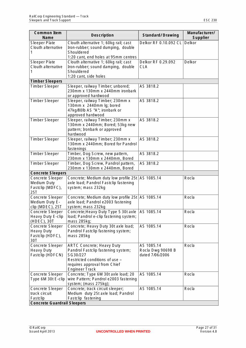
Supplier Sleeper Plate Clouth alternative 1
Clouth alternative 1; 60kg rail; cast Iron-rubber; sound dumping, double Shouldered 1:20 cant, end holes at 95mm centres
Delkor RF 0.10.092 CL Delkor
Sleeper Plate Clouth alternative 1
Clouth alternative 1; 60kg rail; cast Iron-rubber; sound damping, double Shouldered 1:20 cant, side holes
Delkor RF 0.29.092 CLA
Delkor
Timber Sleepers Timber Sleeper Sleeper, railway Timber; unbored;
230mm x 130mm x 2440mm ironbark or approved hardwood
AS 3818.2
Timber Sleeper Sleeper, railway Timber; 230mm x 130mm x 2440mm lg; bored 47kg/80lb AS "A"; ironbark or approved hardwood
AS 3818.2
Timber Sleeper Sleeper, railway Timber; 230mm x 130mm x 2440mm; Bored; 53kg new pattern; Ironbark or approved hardwood
AS 3818.2
Timber Sleeper Sleeper, railway Timber; 230mm x 130mm x 2440mm; Bored for Pandrol fastenings
AS 3818.2
Timber Sleeper Timber, Dog Screw, new pattern, 230mm x 130mm x 2440mm, Bored
AS 3818.2
Timber Sleeper Timber, Dog Screw, Pandrol pattern, 230mm x 130mm x 2440mm, Bored
AS 3818.2
Concrete Sleepers Concrete Sleeper Medium Duty Fastclip (MDFC), 25T
Concrete; Medium duty low profile 25t axle load; Pandrol Fastclip fastening system; mass 232kg
AS 1085.14 Rocla
Concrete Sleeper Medium Duty E-clip (MDEC), 25T
Concrete; Medium duty low profile 25t axle load; Pandrol e2003 fastening system; mass 232kg
AS 1085.14 Rocla
Concrete Sleeper Heavy Duty E-clip (HDEC), 30T
Concrete;Heavy Duty Type 5 30t axle load; Pandrol e-clip fastening system; mass 285kg;
AS 1085.14 Rocla
Concrete Sleeper Heavy Duty Fastclip (HDFC), 30T
Concrete; Heavy Duty 30t axle load; Pandrol Fastclip fastening system; mass 285kg
AS 1085.14 Rocla
Concrete Sleeper Heavy Duty Fastclip (HDFCN)
ARTC Concrete; Heavy Duty Pandrol Fastclip fastening system; SG30/227 Restricted conditions of use – requires approval from Chief Engineer Track
AS 1085.14 Rocla Dwg 90698 B dated 7/06/2006
Rocla
Concrete Sleeper Type 6M 30t E-clip
Concrete; Type 6M 30t axle load; 20 wire Pattern; Pandrol e2003 fastening system; (mass 275kg);
AS 1085.14 Rocla
Concrete Sleeper track circuit Fastclip
Concrete; track circuit sleeper; Medium duty 25t axle load; Pandrol Fastclip fastening
AS 1085.14 Rocla
Concrete Guardrail Sleepers
© RailCorp Page 27 of 31 Issued April 2013 UNCONTROLLED WHEN PRINTED Version 4.8
RailCorp Engineering Standard — Track Sleepers and Track Support ESC 230
Common Item Name Description Standard/ Drawing Manufacturer/
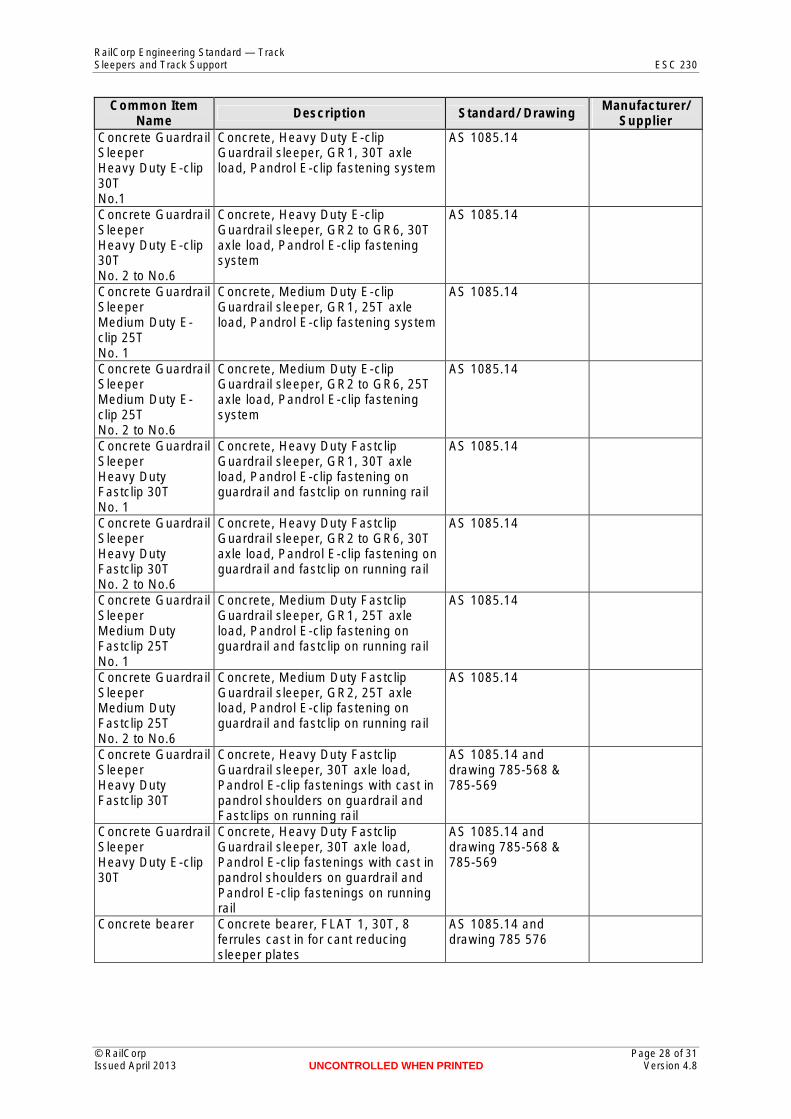
Supplier Concrete Guardrail Sleeper Heavy Duty E-clip 30T No.1
Concrete, Heavy Duty E-clip Guardrail sleeper, GR1, 30T axle load, Pandrol E-clip fastening system
AS 1085.14
Concrete Guardrail Sleeper Heavy Duty E-clip 30T No. 2 to No.6
Concrete, Heavy Duty E-clip Guardrail sleeper, GR2 to GR6, 30T axle load, Pandrol E-clip fastening system
AS 1085.14
Concrete Guardrail Sleeper Medium Duty E-clip 25T No. 1
Concrete, Medium Duty E-clip Guardrail sleeper, GR1, 25T axle load, Pandrol E-clip fastening system
AS 1085.14
Concrete Guardrail Sleeper Medium Duty E-clip 25T No. 2 to No.6
Concrete, Medium Duty E-clip Guardrail sleeper, GR2 to GR6, 25T axle load, Pandrol E-clip fastening system
AS 1085.14
Concrete Guardrail Sleeper Heavy Duty Fastclip 30T No. 1
Concrete, Heavy Duty Fastclip Guardrail sleeper, GR1, 30T axle load, Pandrol E-clip fastening on guardrail and fastclip on running rail
AS 1085.14
Concrete Guardrail Sleeper Heavy Duty Fastclip 30T No. 2 to No.6
Concrete, Heavy Duty Fastclip Guardrail sleeper, GR2 to GR6, 30T axle load, Pandrol E-clip fastening on guardrail and fastclip on running rail
AS 1085.14
Concrete Guardrail Sleeper Medium Duty Fastclip 25T No. 1
Concrete, Medium Duty Fastclip Guardrail sleeper, GR1, 25T axle load, Pandrol E-clip fastening on guardrail and fastclip on running rail
AS 1085.14
Concrete Guardrail Sleeper Medium Duty Fastclip 25T No. 2 to No.6
Concrete, Medium Duty Fastclip Guardrail sleeper, GR2, 25T axle load, Pandrol E-clip fastening on guardrail and fastclip on running rail
AS 1085.14
Concrete Guardrail Sleeper Heavy Duty Fastclip 30T
Concrete, Heavy Duty Fastclip Guardrail sleeper, 30T axle load, Pandrol E-clip fastenings with cast in pandrol shoulders on guardrail and Fastclips on running rail
AS 1085.14 and drawing 785-568 & 785-569
Concrete Guardrail Sleeper Heavy Duty E-clip 30T
Concrete, Heavy Duty Fastclip Guardrail sleeper, 30T axle load, Pandrol E-clip fastenings with cast in pandrol shoulders on guardrail and Pandrol E-clip fastenings on running rail
AS 1085.14 and drawing 785-568 & 785-569
Concrete bearer Concrete bearer, FLAT 1, 30T, 8 ferrules cast in for cant reducing sleeper plates
AS 1085.14 and drawing 785 576
© RailCorp Page 28 of 31 Issued April 2013 UNCONTROLLED WHEN PRINTED Version 4.8
RailCorp Engineering Standard — Track Sleepers and Track Support ESC 230
Common Item Name Description Standard/ Drawing Manufacturer/
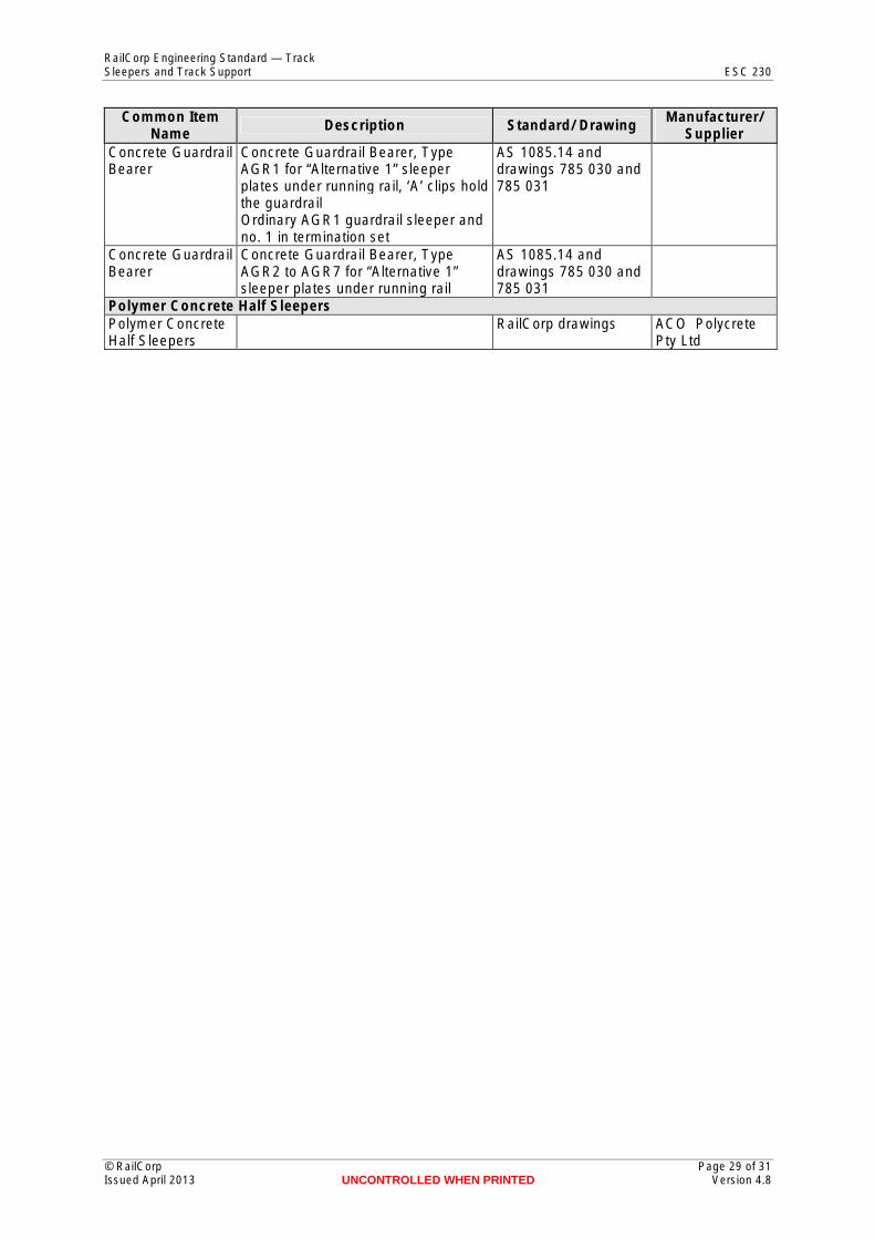
Supplier Concrete Guardrail Bearer
Concrete Guardrail Bearer, Type AGR1 for “Alternative 1” sleeper plates under running rail, ‘A’ clips hold the guardrail Ordinary AGR1 guardrail sleeper and no. 1 in termination set
AS 1085.14 and drawings 785 030 and 785 031
Concrete Guardrail Bearer
Concrete Guardrail Bearer, Type AGR2 to AGR7 for “Alternative 1” sleeper plates under running rail
AS 1085.14 and drawings 785 030 and 785 031
Polymer Concrete Half Sleepers Polymer Concrete Half Sleepers
RailCorp drawings ACO Polycrete Pty Ltd
© RailCorp Page 29 of 31 Issued April 2013 UNCONTROLLED WHEN PRINTED Version 4.8
RailCorp Engineering Standard — Track Sleepers and Track Support ESC 230
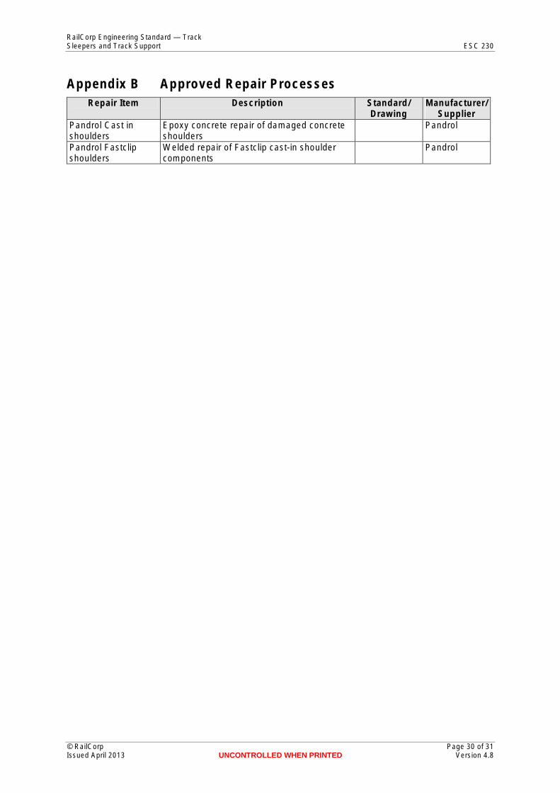
Appendix B Approved Repair ProcessesRepair Item Description Standard/
Drawing Manufacturer/
Supplier Pandrol Cast in shoulders
Epoxy concrete repair of damaged concrete shoulders
Pandrol
Pandrol Fastclip shoulders
Welded repair of Fastclip cast-in shoulder components
Pandrol
© RailCorp Page 30 of 31 Issued April 2013 UNCONTROLLED WHEN PRINTED Version 4.8
RailCorp Engineering Standard — Track Sleepers and Track Support ESC 230
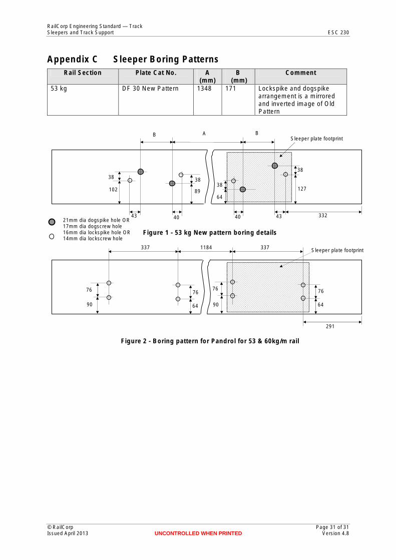
Appendix C Sleeper Boring PatternsRail Section Plate Cat No. A
(mm) B
(mm) Comment
53 kg DF 30 New Pattern 1348 171 Lockspike and dogspike arrangement is a mirrored and inverted image of Old Pattern
Figure 1 - 53 kg New pattern boring details
BAB
43 43 40 40
38
64
332
38 38 38
127 102 89
Sleeper plate footprint
337 1184 337
291
76 76
90 64
Sleeper plate footprint
76
90
76
64
21mm dia dogspike hole OR 17mm dia dogscrew hole 16mm dia lockspike hole OR 14mm dia lockscrew hole
Figure 2 - Boring pattern for Pandrol for 53 & 60kg/m rail
© RailCorp Page 31 of 31 Issued April 2013 UNCONTROLLED WHEN PRINTED Version 4.8
![€¦ · Web view[2] If two clusters of missing sleepers are not separated by a cluster of sleepers with at least an equal number plus one of consecutive effective sleepers and](https://img.pdfslide.us/doc/110x75/5e95ffb00fcff126f66cf300/web-view-2-if-two-clusters-of-missing-sleepers-are-not-separated-by-a-cluster.jpg)


![Outback Sleepers Product Brochure Final[2] · Outback Sleepers offer the highest quality concrete retaining wall sleepers and precast panels, engineered to achieve wall heights in](https://img.pdfslide.us/doc/110x75/5e8fc5dc543b38593c3f803b/outback-sleepers-product-brochure-final2-outback-sleepers-offer-the-highest-quality.jpg)