Embed Size (px)
Citation preview

ESBWR Instrumentation & Controls SystemsDistributed Control and Information Systems (DCIS)
JULY 26-27, 2006
ESBWR
July 26-27, 2006Richard E. Miller
Lungmen Digital Control Room Simulator

2 /GE /
July 28, 2006
ESBWR I&C SYSTEMSAgenda
• Wednesday, July 26
> 0800 – GE - Check-In
> 0830 – GE - Internal Discussions
> 0900 – Entrance Meeting – Introductions
> 0915 – Agenda Overview
> 0930 – Software Plans Overview
> 1400 – Proprietary Discussions – Software Management Plans
• Thursday, July 27
> 0800 – GE - Check-In
> 0830 – GE - Internal Discussions
> 0900 – Entrance Meeting – Introductions
– Distributed Control & Information Systems (DCIS)
• DCIS Platform Families
3 /GE /
July 28, 2006
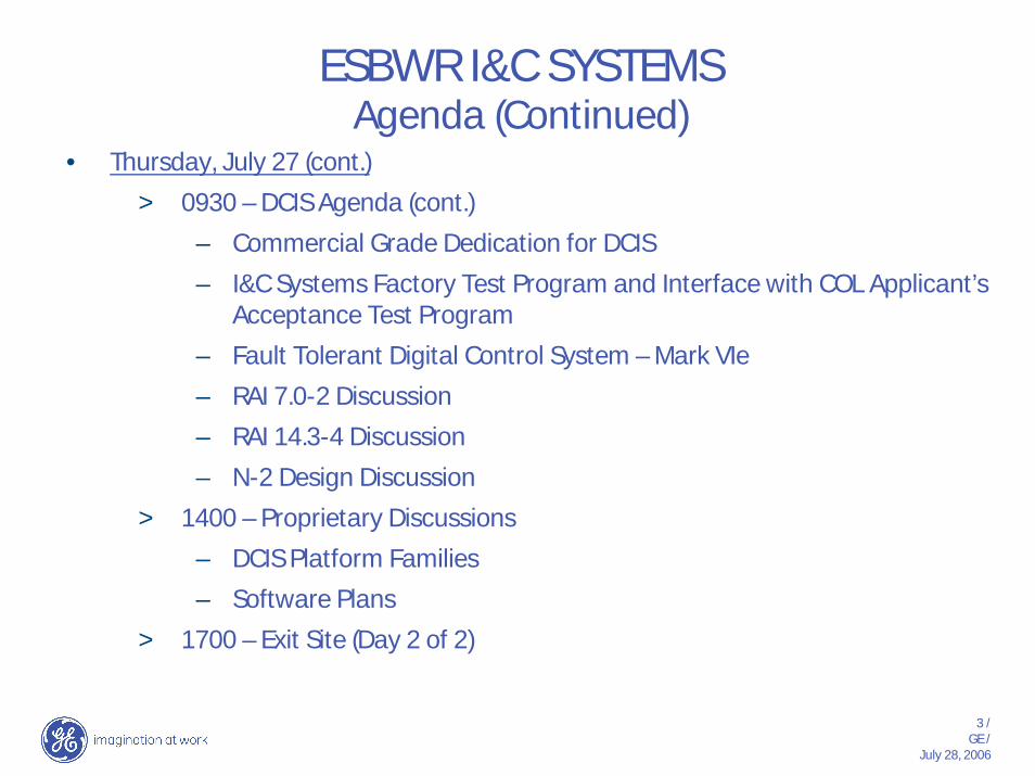
ESBWR I&C SYSTEMSAgenda (Continued)
• Thursday, July 27 (cont.)
> 0930 – DCIS Agenda (cont.)
– Commercial Grade Dedication for DCIS
– I&C Systems Factory Test Program and Interface with COL Applicant’s Acceptance Test Program
– Fault Tolerant Digital Control System – Mark VIe
– RAI 7.0-2 Discussion
– RAI 14.3-4 Discussion
– N-2 Design Discussion
> 1400 – Proprietary Discussions
– DCIS Platform Families
– Software Plans
> 1700 – Exit Site (Day 2 of 2)
4 /GE /
July 28, 2006
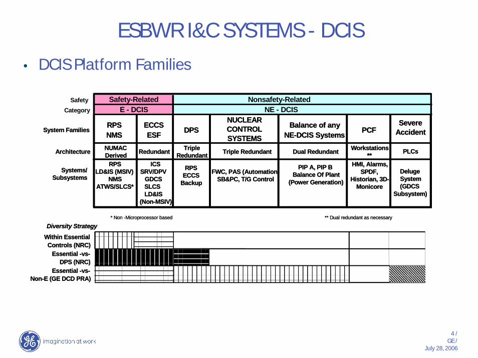
ESBWR I&C SYSTEMS - DCIS• DCIS Platform Families
SafetyCategory
System FamiliesRPSNMS
ECCSESF DPS
NUCLEARCONTROLSYSTEMS
Balance of anyNE-DCIS Systems PCF
Architecture NUMACDerived Redundant Triple
Redundant Triple Redundant Dual Redundant Workstations**
Systems/Subsystems
RPSLD&IS (MSIV)
NMSATWS/SLCS*
ICSSRV/DPV
GDCSSLCS
RPSECCS
Backup
PIP A, PIP BBalance Of Plant
(Power Generation)
Diversity StrategyWithin EssentialControls (NRC)
Essential -vs-DPS (NRC)
Essential -vs-Non-E (GE DCD PRA)
Safety-Related Nonsafety-RelatedE - DCIS NE - DCIS
FWC, PAS (Automation)SB&PC, T/G Control
* Non -Microprocessor based
HMI, Alarms,SPDF,
Historian, 3D-Monicore
** Dual redundant as necessary
SevereAccident
PLCs
DelugeSystem(GDCS
Subsystem)LD&IS(Non-MSIV)
5 /GE /
July 28, 2006
ESBWR I&C SYSTEMS - DCIS
PLC
Hard I/O
RMU
HardI/O
RMU
HardI/O
BOP DUALREDUNDANT
CONTROLLERS(NON SAFETY)
PLC
Hard I/O
RMU
HardI/O
RMU
HardI/O
RMU
PIP BHARD
I/O
RMU
PIP AHARD
I/O
Severe Accident PlatformDeluge System
(Non-Safety)2/2 Logic
Typical ofDual RedundantBOP Controller
Typical ofForeign BOPControllers
TRIPLE REDUNDANT CONTROLLERS
(NON-SAFETY) PLATFORM
Gateway Gateway Gateway GatewayGateway
Dual Redundant PIP A
Controllers
Dual Redundant PIP B
Controllers
Redundant Workstation
Gateway
ECCSRMU
Hard I/O
ECCSRMU
Hard I/O
ECCSRMU
Hard I/O
SRNMPreamps/LPRMS
HardInputs
SRNMPreamps/LPRMS
HardInputs
SRNMPreamps/
LPRMS
HardInputs
RTIFRMU
HardInputs
RTIFRMU
HardInputs
RTIFRMU
HardInputs
SRNMPreamps/LPRMS
HardInputs
RTIFRMU
HardInputs
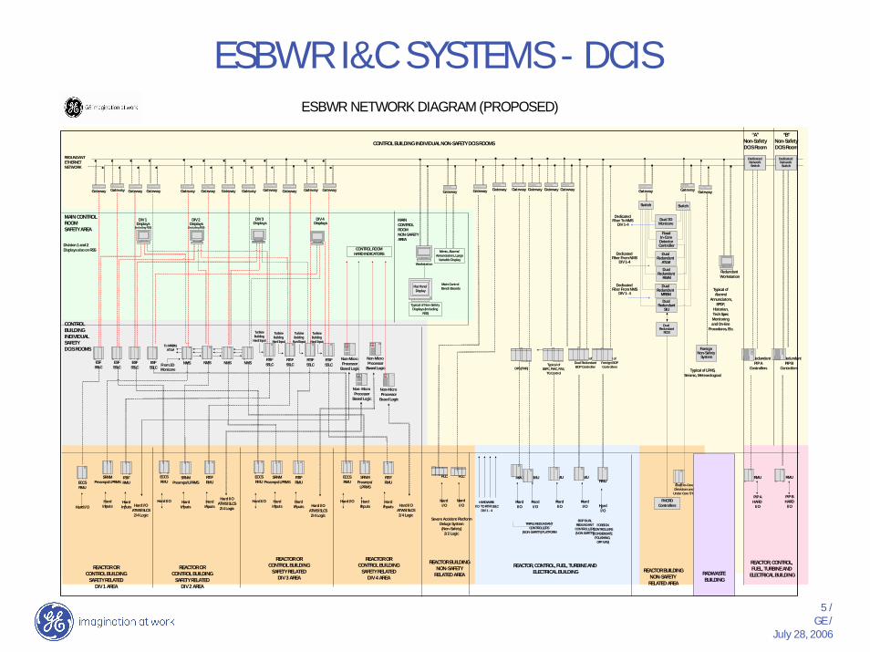
REDUNDANTETHERNETNETWORK
MAIN CONTROLROOMSAFETY AREA
CONTROLBUILDINGINDIVIDUALSAFETYDCIS ROOMS
To MRBM, ATLM
Gateway GatewayGatewayGateway
Non-Micro Processor
Based Logic
Non- Micro Processor
Based Logic
Non-Micro Processor
Based Logic
CONTROL ROOMHARD INDICATORS
Main Control Bench Boards
MAINCONTROLROOMNON-SAFETYAREA
CONTROL BUILDING INDIVIDUAL NON-SAFETY DCIS ROOMS
Non-Micro Processor
Based Logic
REACTOR ORCONTROL BUILDING
SAFETY RELATEDDIV 3 AREA
REACTOR ORCONTROL BUILDING
SAFETY RELATEDDIV 4 AREA
Typical of Non-Safety Displays (Including
RSS)
DIV 3 Displays
DIV 4 Displays
REACTOR BUILDINGNON-SAFETY
RELATED AREA
“A”Non-SafetyDCIS Room
“B”Non-SafetyDCIS Room
Dedicated Network Switch
REACTOR, CONTROL, FUEL, TURBINE AND
ELECTRICAL BUILDING
REACTOR, CONTROL, FUEL, TURBINE AND ELECTRICAL BUILDING
FMCRDControllers
Fixed In-CoreDetectors and
Under Core T/Cs
Dedicated Network
Switch
Workstation
RTIFSSLC
RTIFSSLC
RTIFSSLC
RTIFSSLC
Hard I/OATWS/SLCS2/4 Logic
Dual Redundant
SIU
Dual Redundant
RWM
Dual Redundant
RCIS
Fixed In-Core
Detector Controller
Switch
GatewayGateway
Foreign Non-Safety
System
TurbineBuilding
Hard Input
Gateway GatewayGatewayGatewayGatewayGateway Gateway Gateway
Dedicated Fiber To NMS
DIV 1-4
Dedicated Fiber From NMS
DIV 1-4
Dedicated Fiber From NMS
DIV 1- 4
Dual 3DMonicore
Dual Redundant
ATLM
Dual Redundant
MRBM
HARDWIRE I/O TO RTIF/SSLC
DIV 1 - 4
TurbineBuilding
Hard Input
TurbineBuilding
Hard Input
TurbineBuilding
Hard Input
Mimic, Alarms/Annunciators, Large
Variable Display
GatewayGateway
ECCSRMU
Hard I/O
Switch
NMS NMS NMSNMSESFSSLC
ESFSSLC
ESFSSLC
ESFSSLC
ESBWR NETWORK DIAGRAM (PROPOSED)
RMU
HardI/O
FOREIGNCONTROLLERS(CONDENSATE
POLISHING, OFF GAS)
Typical ofSBPC, FWC, PAS,
TG ControlDPS (TMR)
Division 1 and 2Displays also on RSS
Hard I/OATWS/SLCS2/4 Logic
Hard I/OATWS/SLCS2/4 Logic
Hard I/OATWS/SLCS
2/4 Logic
Flat Panel Display Typical of
Alarms/Annunciators,
SPDF, Historian, Tech Spec Monitoring and On-line
Procedures, Etc.
RADWASTE BUILDING
Typical of LPMS,Seismic, Meteorological
REACTOR BUILDINGNON-SAFETY
RELATED AREA
REACTOR ORCONTROL BUILDING
SAFETY RELATEDDIV 2 AREA
REACTOR ORCONTROL BUILDING
SAFETY RELATEDDIV 1 AREA
From 3D Monicore
DIV 2 Displays
(Including RSS)
DIV 1 Displays
(Including RSS)
6 /GE /
July 28, 2006
ESBWR I&C SYSTEMS - DCIS
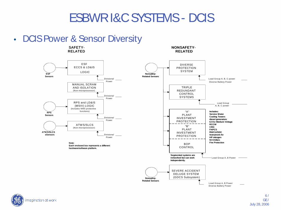
• DCIS Power & Sensor Diversity
RPSSensors
ESFSensors
ESFECCS & LD&IS
LOGIC
SAFETY-RELATED
MANUAL SCRAMAND ISOLATION(Non-microprocessor)
RPS and LD&IS(MSIV) LOGIC
(includes NMS protectivefunctions)
ATW S/SLCS(Non-microprocessor)
Nonsafety-Related Sensors
DIVERSEPROTECTION
SYSTEM
NONSAFETY-RELATED
TRIPLEREDUNDANT
CONTROLSYSTEMS
“A”PLANT
INVESTMENTPROTECTION
“B”PLANT
INVESTMENTPROTECTION
BOPCONTROL
Note:Each enclosed box represents a differenthardware/software platform.
Includes:Service W aterCooling Towersdiesel generators6.9 kv Medium VoltageRCCWCRDFAPCSRW CU/SDCInstrument AirHP nitrogenNI ChillersFire Protection
Segmented systems arenetworked but can workindependently.
ATW S/SLCSsSensors
Nonsafety-Related Sensors
SEVERE ACCIDENTDELUGE SYSTEM(GDCS Subsystem)
DivisionalPower
DivisionalPower
DivisionalPower
DivisionalPower
Load Group A, B, C powerDiverse Battery Power
Load GroupA, B, C power
Load Group A, B Power
Load Group A, B PowerDiverse Battery Power
7 /GE /
July 28, 2006
ESBWR I&C SYSTEMS - DCIS
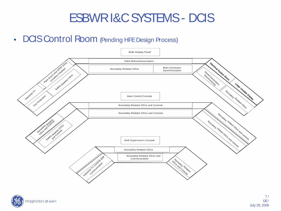
• DCIS Control Room (Pending HFE Design Process)
W ide Display Panel
Plant M im ic/Annunciators
Nonsafety-Related VDUs Main Generator Synchronization
Main Control Console
Nonsafety-Related VDUs and Controls
Nonsafety-Related VDUs
Nonsafety-Related VDUs andCommunication
Shift Supervisor’s Console
Nonsafety-Related VDUs and Contro ls
Nonsafety -Related VDUs
Nonsafety -related VDUs and controls
Nonsafety -related VDUs and controls
Nonsafety -Related
VDUs and Controls
Safety -Related V
DUs
Safety -Related V
DUs
and Contro
ls
Industrial T
V Contro
ls and
Communicatio
n
Nonsafety -R
elated
VDUs and C
ontrols
Fire P
rotection
Industrial T
V
Plant Eve
nt and S
PDF Entry
Condition D
isplays
Electrical System Mimic
Diesel Generators
Synchronizing Large Variable Display

8 /GE /
July 28, 2006
ESBWR I&C SYSTEMS - DCIS
• DCIS and Power SeparationThe raceway, duct bank and conduit systems of the ESBW R aredesigned to provide physical separation of divisional cables from bothother divisions and from nonsafety-related cables.
The raceway system also minimizes the potential for EMI/RFIinterference (already very low because of the extensive use of fiberoptics) by separating instrumentation cabling from large power cables.
Finally RPS and NMS copper cables are conduit separated even withina division to prevent hot shorts and generally prevent any interferencewith a required reactor scram.
13.8 kvNormal Preferred Feed
A Diesel Generator6.9 kv PIP A
Normal Preferred FeedA FMCRD Load Group Feed
480 vac, 120/208 vac, 125vdc, 250 vdc
PIP B, Load Group BFMCRD cables (2nd Group)
B Diesel Generator6.9 kv PIP B
Alternate Preferred FeedB FMCRD Load Group Feed
480 vac, 120/208 vac, 125vdc, 250 vdc
PIP A, Load Group AFMCRD Cables (1st Group)
480 vac, 120/208 vac, 125vdc, 250 vdcLoad Group C
FMCRD Cables (3rd Group)
PIP B
AC or DC Contact InterrogationVoltage, Analog Transmitters,
Ethernet, Data Links, FiberPIP A
AC or DC Contact Interrogation Voltage,Analog Transmitters, Ethernet, Data Links,
Fiber for BOPThird Communication Path for Triply
Redundant Control Systemsnonsafety-related
safety-related
division 1
Division 2Division 1 Division 3
Medium Voltage
Division 4
RPS/NMS/ECCSDivision 2
RPS/NMS/ECCSDivision 1
RPS/NMS/ECCSDivision 3
RPS/NMS/ECCSDivision 4
RPS ScramGroup 1
Division 1
RPS ScramGroup 2
Division 1
RPS ScramGroup 3
Division 1
RPS ScramGroup 4
Division 1
RPS ScramGroup 1
Division 2
RPS ScramGroup 2
Division 2
RPS ScramGroup 3
Division 2
RPS ScramGroup 4
Division 2
13.8 kvAlternate Preferred Feed
Division 2 Division 3 Division 4
480 vac (at isolation phase bus only) > 250 vdc, 120 vac Single-Phase For All Safety Functions
Medium Voltage
Low Voltage
Controls & Instrumentation
Low Voltage
Low Voltage
Controls & Instrumentation
Low Voltage
Controls & Instrumentation
Low Voltage
Controls & Instrumentation
Low Voltage
AC or DC Contact InterrogationVoltage, Analog Transmitters,
Ethernet, Data Links, Fiber
AC or DC Contact InterrogationVoltage, Analog Transmitters,
Ethernet, Data Links, Fiber
AC or DC Contact InterrogationVoltage, Analog Transmitters,
Ethernet, Data Links, Fiber
AC or DC Contact InterrogationVoltage, Analog Transmitters,
Ethernet, Data Links, Fiber
480 vac (at isolation phase bus only) > 250 vdc, 120 vac Single-Phase For All Safety Functions
480 vac (at isolation phase bus only) > 250 vdc, 120 vac Single-Phase For All Safety Functions
480 vac (at isolation phase bus only) > 250 vdc, 120 vac Single-Phase For All Safety Functions
AC or DC Contact InterrogationVoltage, Analog Transmitters,
Ethernet, Data Links, Fiber
The raceway, duct bank and conduit systems of the ESBW R aredesigned to provide physical separation of divisional cables from bothother divisions and from nonsafety-related cables.
The raceway system also minimizes the potential for EMI/RFIinterference (already very low because of the extensive use of fiberoptics) by separating instrumentation cabling from large power cables.
Finally RPS and NMS copper cables are conduit separated even withina division to prevent hot shorts and generally prevent any interferencewith a required reactor scram.
13.8 kvNormal Preferred Feed
A Diesel Generator6.9 kv PIP A
Normal Preferred FeedA FMCRD Load Group Feed
480 vac, 120/208 vac, 125vdc, 250 vdc
PIP B, Load Group BFMCRD cables (2nd Group)
B Diesel Generator6.9 kv PIP B
Alternate Preferred FeedB FMCRD Load Group Feed
480 vac, 120/208 vac, 125vdc, 250 vdc
PIP A, Load Group AFMCRD Cables (1st Group)
480 vac, 120/208 vac, 125vdc, 250 vdcLoad Group C
FMCRD Cables (3rd Group)
PIP B
AC or DC Contact InterrogationVoltage, Analog Transmitters,
Ethernet, Data Links, Fiber
AC or DC Contact InterrogationVoltage, Analog Transmitters,
Ethernet, Data Links, FiberPIP A
AC or DC Contact Interrogation Voltage,Analog Transmitters, Ethernet, Data Links,
Fiber for BOPThird Communication Path for Triply
Redundant Control Systemsnonsafety-related
safety-related
division 1
Division 2Division 1 Division 3
Medium Voltage
Division 4
RPS/NMS/ECCSDivision 2
RPS/NMS/ECCSDivision 1
RPS/NMS/ECCSDivision 3
RPS/NMS/ECCSDivision 4
RPS ScramGroup 1
Division 1
RPS ScramGroup 2
Division 1
RPS ScramGroup 3
Division 1
RPS ScramGroup 4
Division 1
RPS ScramGroup 1
Division 2
RPS ScramGroup 2
Division 2
RPS ScramGroup 3
Division 2
RPS ScramGroup 4
Division 2
13.8 kvAlternate Preferred Feed
Division 2 Division 3 Division 4
480 vac (at isolation phase bus only) > 250 vdc, 120 vac Single-Phase For All Safety Functions
Medium Voltage
Low Voltage
Controls & Instrumentation
Low Voltage
Low Voltage
Controls & Instrumentation
Low Voltage
Controls & Instrumentation
Low Voltage
Controls & Instrumentation
Low Voltage
AC or DC Contact InterrogationVoltage, Analog Transmitters,
Ethernet, Data Links, Fiber
AC or DC Contact InterrogationVoltage, Analog Transmitters,
Ethernet, Data Links, Fiber
AC or DC Contact InterrogationVoltage, Analog Transmitters,
Ethernet, Data Links, Fiber
AC or DC Contact InterrogationVoltage, Analog Transmitters,
Ethernet, Data Links, Fiber
AC or DC Contact InterrogationVoltage, Analog Transmitters,
Ethernet, Data Links, Fiber
AC or DC Contact InterrogationVoltage, Analog Transmitters,
Ethernet, Data Links, Fiber
AC or DC Contact InterrogationVoltage, Analog Transmitters,
Ethernet, Data Links, Fiber
AC or DC Contact InterrogationVoltage, Analog Transmitters,
Ethernet, Data Links, Fiber
480 vac (at isolation phase bus only) > 250 vdc, 120 vac Single-Phase For All Safety Functions
480 vac (at isolation phase bus only) > 250 vdc, 120 vac Single-Phase For All Safety Functions
480 vac (at isolation phase bus only) > 250 vdc, 120 vac Single-Phase For All Safety Functions
AC or DC Contact InterrogationVoltage, Analog Transmitters,
Ethernet, Data Links, Fiber
AC or DC Contact InterrogationVoltage, Analog Transmitters,
Ethernet, Data Links, Fiber

9 /GE /
July 28, 2006
ESBWR I&C SYSTEMS - DCIS
Proposed Suppliers for Primary DCIS Families• NMS/RPS > GE (NUMAC)
• ECCS/ESF > GE/DS-S (Spinline 3), DRS (Performnet), HF-C (6000 Series), or Invensys (Triconex)
• DPS > GE (Mark VIe)
• Nuclear Control Systems > GE (Mark VIe)
• Balance of Any Nonsafety-Related Systems > GE (Mark VIe) or Invensys (Foxboro)
• Plant Computer Functions > (GE-Mark VIe / DS-S (SAIPMS/Win)
• Severe Accident > Quality Diverse PLC Supplier
• 3rd Party DCIS Suppliers > Various
10 /GE /
July 28, 2006
ESBWR I&C SYSTEMS - DCIS
Open DCIS Discussion
11 /GE /
July 28, 2006
ESBWR I&C SYSTEMS - DCIS
• Commercial Grade Dedication for DCIS• DCD Chapter 7, Appendix 7B.2 Software Management Plan,
Paragraph (2)e and DCD Chapter 7, Appendix 7B.4 Software Configuration Management Plan, Paragraph (3) h reference:
• CR-G421, “A Proposed Acceptance Process for Commercial Off-the-shelf (COTS) Software in Reactor Applications”
• EPRI TR-106439, Guidelines on Evaluation and Acceptance of Commercial Grade Digital Equipment in Nuclear Safety Applications

12 /GE /
July 28, 2006
ESBWR I&C SYSTEMS - DCIS
• Commercial Grade Dedication for DCIS (cont.)• DCD Chapter 7, Section 7.2, Reactor Trip System and
Neutron Monitoring System, BTP HICB-18, Guidance on Use of Commercial Grade Industrial Computers) in Digital Computer-based Instrumentation and Control systems
• Any portions of RPS, NMS and SSLC/ESF design that will use Commercial Grade Industrial Computers for safety-related functions conform to this BTP (and to BTPs 14, 17, and 21). Such commercial grade industrial computers will be qualified to a level commensurate with safety requirements.
13 /GE /
July 28, 2006
ESBWR I&C SYSTEMS - DCIS
Break
14 /GE /
July 28, 2006
ESBWR I&C SYSTEMS - DCIS
• I&C Systems Factory Test Program and Interface with COL Applicant’s Acceptance Test Program
• Discussion

15 /GE /
July 28, 2006
ESBWR I&C SYSTEMS - DCIS
Break

16 /GE /
July 28, 2006
ESBWR I&C SYSTEMS - DCIS
• Fault Tolerant Digital Control System – Mark VIe• DCD Figure
• Discussion
17 /GE /
July 28, 2006
ESBWR I&C SYSTEMS - DCIS
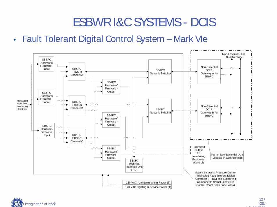
• Fault Tolerant Digital Control System – Mark VIe
12 /GE /
July 21 2006
SB&PCFTDC-R
Channel A
SB&PCFTDC-S
Channel B
SB&PCFTDC-T
Channel C
SB&PCTechnical
Interface Unit(TIU)
SB&PCNetwork Switch A
SB&PCNetwork Switch B
Non-EssentialDCIS
Gateway A forSB&PC
Non-EssentialDCIS
Gateway B forSB&PC
Non-Essential DCISDual Network
HardwiredInput fromInterfacingControls
SB&PCHardware/Firmware -
Output
SB&PCHardware/Firmware -
Output
SB&PCHardware/Firmware -
Output
HardwiredOutput
ToInterfacingEquipment/Controls
Steam Bypass & Pressure ControlTriplicated Fault Tolerant Digital
Controller (FTDC) and SupportingComponents (Panel Located inControl Room Back Panel Area)
Part of Non-Essential DCISLocated in Control Room
120 VAC (Uninterrruptible) Power (3)
120 VAC Lighting & Service Power (1)
SB&PCHardware/Firmware -
Input
SB&PCHardware/Firmware -
Input
SB&PCHardware/Firmware -
Input
• Fault Tolerant Digital Control System – Mark VIe
ESBWR I&C SYSTEMS - DCIS

18 /GE /
July 28, 2006
ESBWR I&C SYSTEMS - DCIS
• RAI 7.0-2 Discussion• NRC RAI 7.0-2• 10 CFR 52.47(a)(2) requires that the information submitted for a design certification must
include performance requirements and design information sufficiently detailed to permit the preparation of acceptance and inspection requirements by the NRC, and procurement specifications and construction and installation specifications by an applicant. For any ESBWR application software developed by GE, and described in DCD Appendix 7B, please provide the following software life-cycle documents:
• - Requirements Definition• - Integration Plan
• - Test Plan

19 /GE /
July 28, 2006
ESBWR I&C SYSTEMS - DCIS
• RAI 7.0-2 Discussion (cont.)• GE Draft Response to RAI 7.0-2
• Establishing performance requirements and specifying design information are part of the software life cycle process and are discussed in DCD Tier 2, section 7B.2 (3), “Software Management Plan”. This process is further described in NEDE-33226, “ESBWR I&C Software Management Plan”.
• The detailed ESBWR software life cycle process design output documents, which are created and reviewed during the life-cycle phases referred to in the RAI and as reflected in Section 2.1 of the HICB-14, will be developed and available for NRC audit and inspection during the software life cycle process.
• Specifically DG-1145,“Combined License Applications for Nuclear Power Plants” Section C.II.2, Attachment A, Software Requirements Specifications states “The ITACC should require verification that each of the functional characteristics shown in SRP Chapter 7, BTP 7-14, has been addressed, and specifically require a verification that each individual requirement is traceable to a digital system requirement, and that there are no added functions or requirements which are not traceable to the system requirement.” DCD, Section 7B.2(3)b, “Design Definition Requirements Phase,” provides for the output documents that will document system requirement specifications.
20 /GE /
July 28, 2006
ESBWR I&C SYSTEMS - DCIS
• RAI 7.0-2 Discussion (cont.)• GE Draft Response to RAI 7.0-2 (cont.)
• DG-1145 Section C.II.2, Attachment A, also states that the ITACC for software life cycle process output documents should demonstrate that “The system test procedures and test results (validation tests, site acceptance tests, pre-operational and start-up tests) provide assurance that the system functions as intended.” DCD Section 7B.2(3)e “Integration Test Phase” provides for the output documents that will provide the required assurance.
• DG-1145 was recently issued in draft form. Attachment A of Section C.II.2 provides general development guidance on ITACC related to the subject software life cycle process design output documents. GE is currently evaluating that additional guidance and will incorporate any changes to the ESBWR ITACC for software related activities as warranted.
21 /GE /
July 28, 2006
ESBWR I&C SYSTEMS - DCIS
• RAI 14.3-4 Discussion• NRC RAI 14.3-4 Requirements to be addressed by DCD Tier 1, Section 2.2.7, Reactor
protection System (RPS).
• The RPS can withstand seismic design basis loads without loss of safety function.
• The RPS has electrical surge withstand capability (SWC), and can withstand electromagnetic interface (EMI), radio frequency interface (RFI), and electrostatic discharge (ESD) conditions that would exist before, during, and following a design basis accident without loss of safety function.
• The RPS can withstand the room ambient temperature, humidity, pressure, and mechanical vibration conditions that would exist before, during, and following a design basis accident without loss of safety function.
• The RPS is powered from Class 1E division.
22 /GE /
July 28, 2006
ESBWR I&C SYSTEMS - DCIS
• RAI 14.3-4 Discussion (cont.)• NRC RAI 14.3-4 Requirements to be addressed by DCD Tier 1, Section 2.2.7, Reactor
protection System (RPS). (cont.)
• The RPS provides process signals to the Essential Distributed Control and Information System (E-DCIS) through isolation devices. Data Communication between safety and non safety systems does not inhibit the performance of the safety function.
• The RPS provides the transfer of control capability from the main control room to the remote shutdown panel.
• The RPS trip setpoints are determined using a methodology which accounts for loop accuracies, and accommodates response time testing.
• The RPS hardware and software is developed using a planned life cycle process.

23 /GE /
July 28, 2006
ESBWR I&C SYSTEMS - DCIS
Break
24 /GE /
July 28, 2006
ESBWR I&C SYSTEMS - DCIS
• N-2 Design Discussion• Problem Statement• Design Change• Impacts

25 /GE /
July 28, 2006
ESBWR I&C SYSTEMS - DCIS
Break
26 /GE /
July 28, 2006
ESBWR I&C SYSTEMS - DCIS
• Proprietary Discussions– DCIS– Software
27 /GE /
July 28, 2006
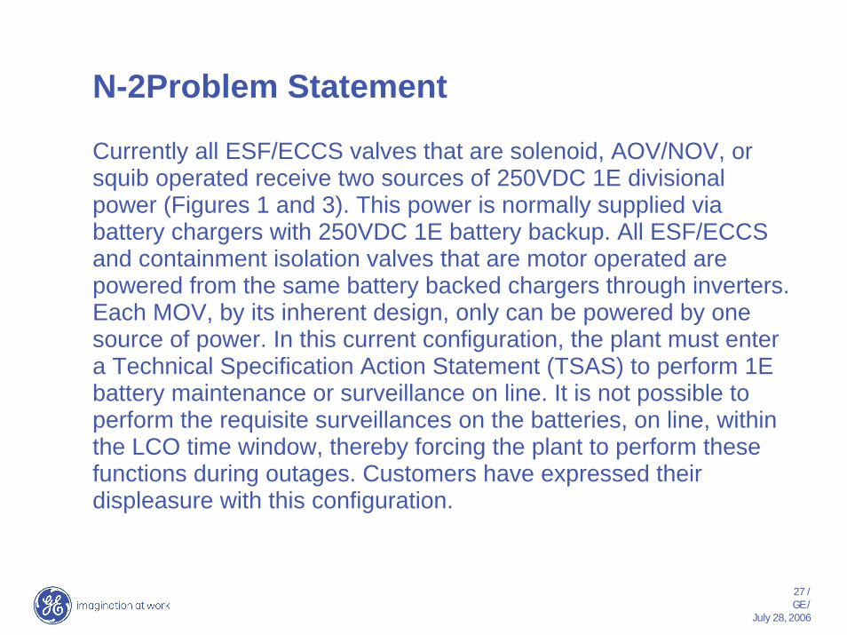
N-2Problem Statement
Currently all ESF/ECCS valves that are solenoid, AOV/NOV, or squib operated receive two sources of 250VDC 1E divisional power (Figures 1 and 3). This power is normally supplied via battery chargers with 250VDC 1E battery backup. All ESF/ECCS and containment isolation valves that are motor operated are powered from the same battery backed chargers through inverters.Each MOV, by its inherent design, only can be powered by one source of power. In this current configuration, the plant must enter a Technical Specification Action Statement (TSAS) to perform 1E battery maintenance or surveillance on line. It is not possible to perform the requisite surveillances on the batteries, on line, within the LCO time window, thereby forcing the plant to perform these functions during outages. Customers have expressed their displeasure with this configuration.
28 /GE /
July 28, 2006
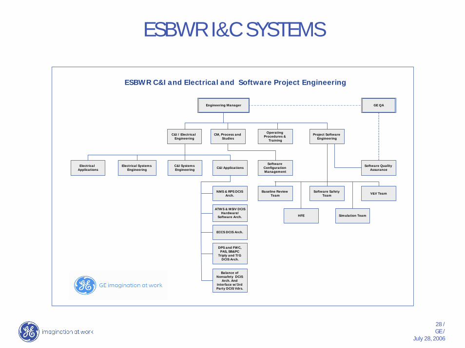
ESBWR I&C SYSTEMS
ESBW R C&I and Electrical and Softw are Project Engineering
Electrical System s Engineering
H FE
Electrical Applications
ATW S & M SIV DCIS Hardw are/
Softw are Arch.
ECCS DCIS Arch.
DPS and FW C, PAS, SB&PC
Triply and T/G DCIS Arch.
Balance of N onsafety DCIS
Arch. And Interface w /3rd Party DCIS Vdrs.
Sim ulation Team
Project Softw are Engineering
GE Q A
CM , Process and Studies
O perating Procedures &
Training
C&I / Electrical Engineering
C&I System s Engineering
C&I Applications
N M S & RPS DCIS Arch.
Engineering M anager
Softw are Quality Assurance
Softw are Configuration M anagem ent
Softw are Safety Team
V&V TeamBaseline Review
Team

Backup
30 /GE /
July 28, 2006
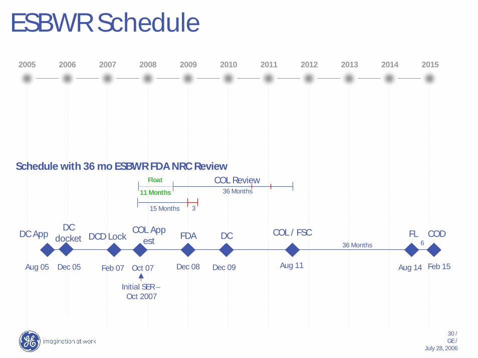
ESBWR Schedule2006
Schedule with 36 mo ESBWR FDA NRC Review
DC App FDACOL App
est
Initial SER –Oct 2007
36 Months
Feb 15
6DC
DC docket
15 Months
Dec 08 Aug 11 Aug 14Aug 05 Dec 09Dec 05 Oct 07Feb 07
36 Months11 Months
Float
3
COL Review
2005 2007 2008 2009 2010 2011 2012 2013 2014 2015
COL / FSC FL CODDCD Lock
31 /GE /
July 28, 2006
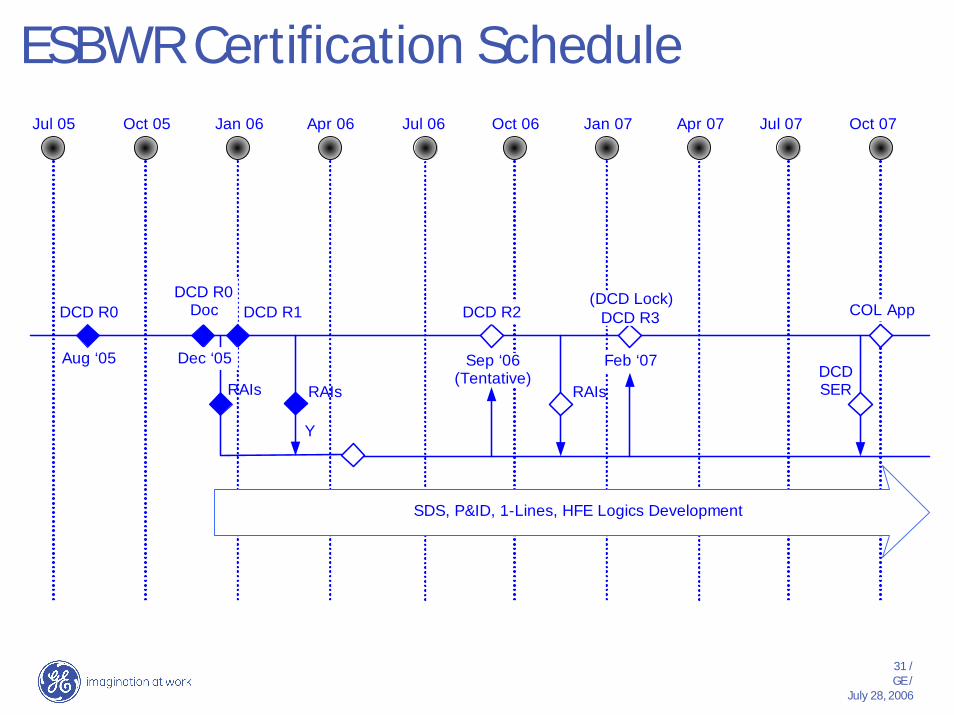
ESBWR Certification ScheduleJul 05 Oct 05 Jan 06 Apr 06 Jul 06 Oct 06 Jan 07 Apr 07 Jul 07 Oct 07
DCD R0
Aug ‘05
DCD R0Doc
Dec ‘05
DCD R1 DCD R2
RAIs
Y
RAIs
Sep ‘06(Tentative)
(DCD Lock)DCD R3
Feb ‘07
COL App
RAIs
SDS, P&ID, 1-Lines, HFE Logics Development
DCDSER
Regulatory Interactions
33 /GE /
July 28, 2006
Regulatory Interactions
• RAIs Topics Currently Open> 7.0-2
> D3 Report
34 /GE /
July 28, 2006
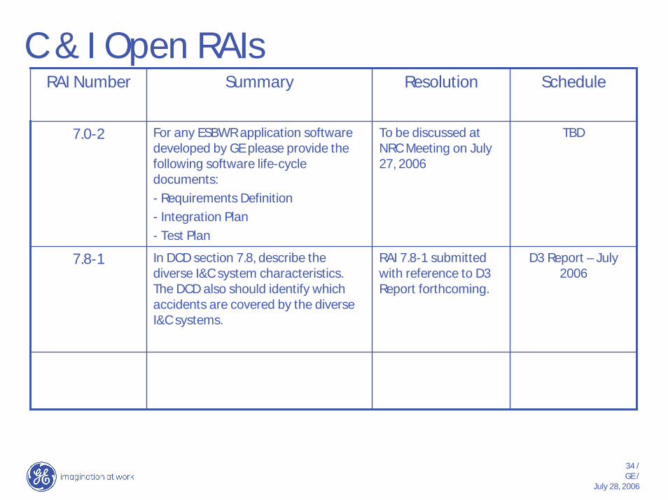
C & I Open RAIs
D3 Report – July 2006
RAI 7.8-1 submitted with reference to D3 Report forthcoming.
In DCD section 7.8, describe the diverse I&C system characteristics. The DCD also should identify which accidents are covered by the diverse I&C systems.
7.8-1
TBDTo be discussed at NRC Meeting on July 27, 2006
For any ESBWR application software developed by GE please provide the following software life-cycle documents: - Requirements Definition - Integration Plan - Test Plan
7.0-2
ScheduleResolutionSummaryRAI Number
35 /GE /
July 28, 2006
C & I Open RAIs cont’d
ScheduleResolutionSummaryRAI Number

36 /GE /
July 28, 2006
HFE Open RAIs
ScheduleResolutionSummaryRAI Number
Challenges
38 /GE /
July 28, 2006
Challenges
39 /GE /
July 28, 2006
Design Completeness Examples
Control Room HFE and V&V

40 /GE /
July 28, 2006

41 /GE /
July 28, 2006
42 /GE /
July 28, 2006
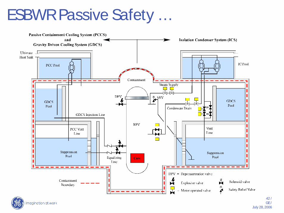
ESBWR Passive Safety …
43 /GE /
July 28, 2006
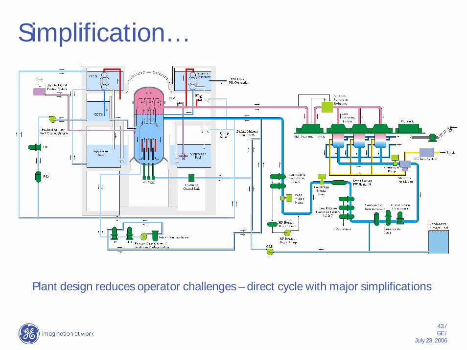
Simplification…
Plant design reduces operator challenges – direct cycle with major simplifications
44 /GE /
July 28, 2006
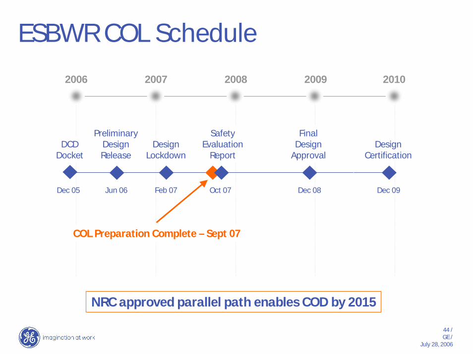
ESBWR COL Schedule2006 2007 2008 2009 2010
SafetyEvaluation
Report
Feb 07 Dec 08 Dec 09Dec 05 Oct 07Jun 06
DesignLockdown
COL Preparation Complete – Sept 07
DesignCertification
PreliminaryDesignRelease
FinalDesign
ApprovalDCD
Docket
NRC approved parallel path enables COD by 2015