Embed Size (px)
Citation preview
ESBE SYSTEM UNITSCIRCULATION UNIT
Mtrl.nr. 98140917 • Ritn.nr. 7553 utg. B • Rev. 1512
2-6
7-11
12-16
17-21
22-26
27-31
CIRCULATION UNIT
SHUNTGRUPP
PUMPENGRUPPE
GRUPPO DI CIRCOLAZIONE
GROUPE HYDRAULIQUES
GRUPA POMPOWA
DE
IT
FR
PL
GB
SE
2 (31)
ESBE SYSTEM UNITSCIRCULATION UNIT
Series and Function • General/Safety
Hydraulic Installation • Electric Installation • Commissioning
Circulation pump, operation mode WILO
WILO Faults, Causes and Remedies • Circulation pump, operation mode GRUNDFOS
How to use the information leaflet • Maintenance • Spare parts
PAGE CONTENT
2
3
4
5
6
GENERAL/SAFETY
LVD 2014/35/EUEMC 2014/30/EURoHS 2011/65/EUPED 2014/68/EU, article 4.3zz Max. operating pressure: PN 6
This instruction manual is an essential component of the product. Read the instructions and the warnings carefully as they contain important information about a safe installation, usage and maintenance.
This product can be used only for the circulation of water and water/glycol in heating or cooling installations.
INSTALLATION EXAMPLE
All piping schematics are general representations
The producer won´t be responsible for damages caused by wrong usage or unrespect of the instructions given in this manual.
The mounting of the unit must be performed by a qualified professional and in compliance with local/regional laws. This manual refers to standard products. Different versions or functions are available.
At mounting - pay attention and follow common practice and general safety norms for the use of machineries, pressurized equipment and at high temperatures.
For electrical components integrated into this product copies of corresponding CE declaration are part of this instruction.
Actuator/Controller Circulation pumpGrundfos
54
UPM3
EC declaration of conformityWe, Grundfos, declare under our sole responsibility that the products GFNJB (UPM variants with user interface) and GFNJC (other UPM3 variants) , to which this declaration relates, are in conformity with these Council directives on the approximation of the laws of the EC member states:
Low Voltage Directive (2006/95/EC)Standards used:
EN 60335-1:2012/AC:2014EN 60335-2-51:2003/A1:2008/A2:2012
EMC Directive (2004/108/EC)Standards used:
EN 55014-1:2006/A1:2009EN 55014-2:1997/A1:2001/A2:2008
Ecodesign Directive (2009/125/EC)Commission Regulation (EC) No 641/2009Commission Regulation (EC) No 622/20012Standards used:
EN 16297-1:2012EN 16297-2:2012EN 16297-3:2012
WarningThe use of this product requires experience with and knowledge of the product. Persons with reduced physical, sensory or mental capabilities must not use this product, unless they are under supervision or have been instructed in the use of the product by a person responsible for their safety. Children must not use or play with this product.
Bjerringbro, 21st of February 2014
Preben Jakobsen Technical Manager - HVAC OEM
GRUNDFOS Holding A/SPoul Due Jensens Vej 7
8850 Bjerringbro, Denmark
Person authorised to compile technical file and empowered to sign the EC declaration of conformity.
VDE certificateThese pumps are certified by VDE.Product code: GFNJB or GFNJCVDE certificate No. 40039416This Marks Approval forms the basis of the CE declaration of conformity and the CE marking by the manufacturer or his agent and proves the conformity with the essential safety requirements of the EC Low Voltage Directive (2006/95/EC) including amendments.
Approvals and certificates
Circulation pumpWilo
The supplier: Le Fabricant : Der Hersteller:
WILO INTEC 50 Avenue Eugène CASELLA 18700 AUBIGNY SUR NERE FRANCE
certifies that the following pumps, déclare que le type de circulateurs désigné ci-dessous, erklärt, dass die unten genannten Pumpentypen,
WILO YONOS PARA RK WILO YONOS PARA PWM
are meeting the requirements of the European legislation concerning: sont conformes aux dispositions des directives : mit folgenden Richtlinien übereinstimmen:
and the national legislations referring to them. et aux législations nationales les transposant. und entsprechender nationaler Gesetzgebung.
They are also meeting the following European Standards: Elles sont également conformes aux dispositions des normes européennes harmonisées suivantes : Des weiteren entsprechen sie den folgenden harmonisierten europäischen Normen:
NF EN 60.335.1&2.51
If the above mentioned series are technically modified without our approval, this declaration shall no longer be applicable. Si les séries mentionnées ci-dessus sont techniquement modifiées sans notre approbation, cette déclaration ne sera plus applicable. Bei einer mit uns nicht abgestimmten technischen Änderung der oben genannten Bauarten, verliert diese Erklärung ihre Gültigkeit.
M.PERROT
Quality Manager
Aubigny-sur-Nère, the 29th of November 2011
~ "Low Voltage" modified (European law Nr 2006/95/EC) ~ "Basse Tension"modifiée (Directives 2006/95/CE) ~ geänderte "Niederspannung" (Richtlinie 2006/95/EG)
~ "Electromagnetic Compatibility" modified (European law Nr 2004/108/EC) ~ "Compatibilité Electromagnétique" modifiée (Directives 2004/108/CE) ~ geänderte "elektromagnetische Verträglichkeit" (Richtlinie 2004/108/EG)
EC DECLARATION OF CONFORMITY DECLARATION DE CONFORMITE CE
EG KONFORMITÄTSERKLÄRUNG
We reserve the right to modify or improve the product, its technical data and literature at any time and without notice.
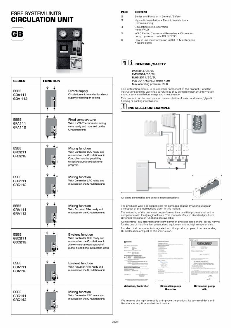
SERIES FUNCTION
ESBE GDA111GDA 112
Direct supplyCirculation unit intended for direct supply of heating or cooling.
ESBE GFA111GFA112
Fixed temperatureWith a VTA Thermostatic mixing valve ready and mounted on the Circulation unit.
ESBE GRC211GRC212
Mixing functionWith Controller 90C ready and mounted on the Circulation unit.Controller has the possibility to control pump through time program.
ESBE GRC111GRC112
Mixing functionWith Controller CRC ready and mounted on the Circulation unit.
ESBE GRA111GRA112
Mixing functionWith Actuator ARA ready and mounted on the Circulation unit.
ESBE GBC211GBC212
Bivalent functionWith Controller 90C ready and mounted on the Circulation unit.Allows simultaneous control of pump in additional Circulation units.
ESBE GBA111GBA112
Bivalent functionWith Actuator ARA ready and mounted on the Circulation unit.
ESBE GRC141GRC142
Mixing functionWith Controller CRD ready and mounted on the Circulation unit.
3 (31
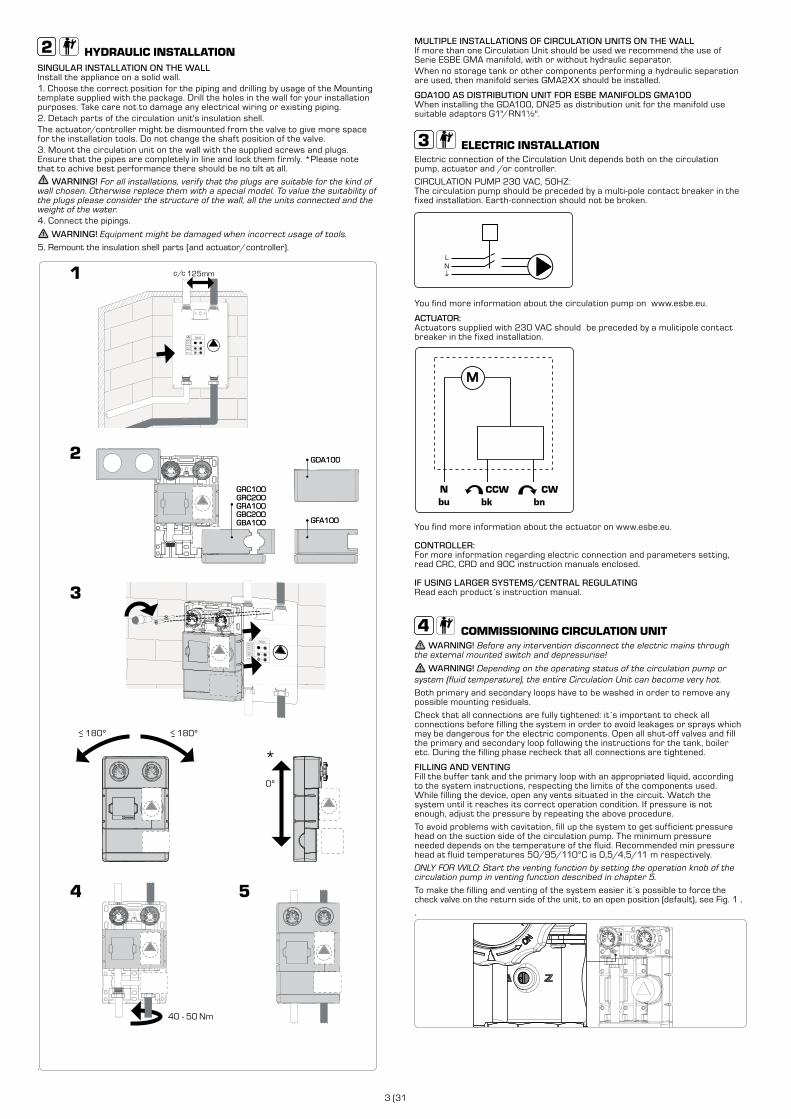
HYDRAULIC INSTALLATIONSINGULAR INSTALLATION ON THE WALL Install the appliance on a solid wall.1. Choose the correct position for the piping and drilling by usage of the Mounting template supplied with the package. Drill the holes in the wall for your installation purposes. Take care not to damage any electrical wiring or existing piping. 2. Detach parts of the circulation unit's insulation shell.The actuator/controller might be dismounted from the valve to give more space for the installation tools. Do not change the shaft position of the valve.3. Mount the circulation unit on the wall with the supplied screws and plugs. Ensure that the pipes are completely in line and lock them firmly. *Please note that to achive best performance there should be no tilt at all.
WARNING! For all installations, verify that the plugs are suitable for the kind of wall chosen. Otherwise replace them with a special model. To value the suitability of the plugs please consider the structure of the wall, all the units connected and the weight of the water. 4. Connect the pipings.
WARNING! Equipment might be damaged when incorrect usage of tools.
5. Remount the insulation shell parts (and actuator/controller).
.
GDA100
GFA100
GRC100GRC200GRA100GBC200GBA100
180º>180º>
0º
GDA100
GFA100
40 - 50 Nm
GRC100GRC200GRA100GBC200GBA100
*
MULTIPLE INSTALLATIONS OF CIRCULATION UNITS ON THE WALLIf more than one Circulation Unit should be used we recommend the use of Serie ESBE GMA manifold, with or without hydraulic separator. When no storage tank or other components performing a hydraulic separation are used, then manifold series GMA2XX should be installed.
GDA100 AS DISTRIBUTION UNIT FOR ESBE MANIFOLDS GMA100When installing the GDA100, DN25 as distribution unit for the manifold use suitable adaptors G1"/RN1½".
ELECTRIC INSTALLATIONElectric connection of the Circulation Unit depends both on the circulation pump, actuator and /or controller.
CIRCULATION PUMP 230 VAC, 50HZ:The circulation pump should be preceded by a multi-pole contact breaker in the fixed installation. Earth-connection should not be broken.
LN
You find more information about the circulation pump on www.esbe.eu.
ACTUATOR:Actuators supplied with 230 VAC should be preceded by a mulitipole contact breaker in the fixed installation.
M
You find more information about the actuator on www.esbe.eu.
CONTROLLER:For more information regarding electric connection and parameters setting, read CRC, CRD and 90C instruction manuals enclosed.
IF USING LARGER SYSTEMS/CENTRAL REGULATING Read each product s instruction manual.
COMMISSIONING CIRCULATION UNIT WARNING! Before any intervention disconnect the electric mains through
the external mounted switch and depressurise!
WARNING! Depending on the operating status of the circulation pump or system (fluid temperature), the entire Circulation Unit can become very hot.
Both primary and secondary loops have to be washed in order to remove any possible mounting residuals.
Check that all connections are fully tightened: it s important to check all connections before filling the system in order to avoid leakages or sprays which may be dangerous for the electric components. Open all shut-off valves and fill the primary and secondary loop following the instructions for the tank, boiler etc. During the filling phase recheck that all connections are tightened.
FILLING AND VENTINGFill the buffer tank and the primary loop with an appropriated liquid, according to the system instructions, respecting the limits of the components used. While filling the device, open any vents situated in the circuit. Watch the system until it reaches its correct operation condition. If pressure is not enough, adjust the pressure by repeating the above procedure.
To avoid problems with cavitation, fill up the system to get sufficient pressure head on the suction side of the circulation pump. The minimum pressure needed depends on the temperature of the fluid. Recommended min pressure head at fluid temperatures 50/95/110°C is 0,5/4,5/11 m respectively.
ONLY FOR WILO: Start the venting function by setting the operation knob of the circulation pump in venting function described in chapter 5.
To make the filling and venting of the system easier it s possible to force the check valve on the return side of the unit, to an open position (default), see Fig. 1 .
.

4 (31)
In most cases it is suitable to position the red knob in the middle position to the left (ΔP-v) to get the appropriate capacity from the circulation pump, especially when radiators are used.
In some cases this setting has to be adjusted: If much sound occurs from the radiator system, the capacity of the circulation pump might be too high and the red knob should be slightly turned towards the min position.
If room temperature decrease when it is very cold outside, the red knob should be slightly turned toward the max position.
When using applications like floor heating with room ther-mostats, the performance might be improved by choosing to turn the knob to the right side (ΔP-c). Start in a middle position.
VARIABLE DIFFERENTIAL PRESSURE (ΔP-V) :The differential-pressure set point H is increased linearly over the permitted volume flow range between ½ H and H. This control mode is especially useful in heating systems with radiators, since flow noise at the thermostatic valves is reduced.
CONSTANT DIFFERENTIAL PRESSURE (ΔP-C):The differential-pressure set point H is kept constant over the permitted volume flow range at the selected differential-pressure set point up to the maximum circulation pump curve. ESBE recommends this control mode for underfloor-heating circuits or older heating systems with large-sized pipes as well as for all applications with no changeable pipe system curve, e.g. boiler charge circulation pumps.
H
H max
H s
½ H s
H min
Q
H
H max
H s
½ H s
H min
Q
FILLING AND VENTING FUNCTIONFill and vent the system correctly. If direct venting of the rotor chamber is required, the venting function can be started manually. By turning the operating knob to the symbol for venting in the middle position, the venting function is activated after 3 seconds.
The venting function lasts 10 minutes and is indicated with quick green LED blinking. Noises may be heard when the venting function is running. The process can be stopped if desired by turning the knob. After 10 minutes, the circulation pump stops and goes automatically in Δp-c max mode.
WARNING! Dont forget to turn the knob back to recommended setting!
NOTE: The venting function removes accumulated air from the rotor chamber of the circulation pump. The venting function of the circulation pump does not necessarily vent the heating system.
During automatic venting function (10min) the circulation pump alternates between high and low speeds in order for air bubbles to be released from the rotor and transported to the venting valve of the installation.
AUTOMATIC AIR VENTING ROUTINE
high speed
low speed
l/min
high speed
t
low speed
10 min
After a complete filling and venting, turn the screw on the check valve back to it s normal operating position, picture 2 and set the circulation pump operation to recommended position. See chapter 5 Wilo and chapter 6 Grundfos.
COMMISSIONING ACTUATOR:During commisioning it might be useful to turn the valve manualy by pulling the knob, picture A. Reset to operation mode by pushing and adjusting the knob back, picture B.
1
COMMISSIONING CONTROLLER: For more information regarding comissioning, read CRC, CRD or 90C instruction manuals enclosed.
COMMISSIONING IF USING LARGER SYSTEMS/CENTRAL REGULATING Please read each product s instruction manual.
COMMISSIONING FIXED TEMPERATURE OPERATIONTo set the mixed water temperature, see recommendations in the table below. All temperature settings must be measured at suitable location with a thermometer to have the correct mixing temperature of the valve.
20 - 43°C 20°C 27°C 31°C 35°C 39°C 43°C
The temperatures are only a reference and might be different under certain conditions. However the range will be kept.
WILO - CIRCULATION PUMP
OPERATION MODEAll functions can be set, activated or deactivated by using the operating knob. The circulation pump is equipped with a LED indicator in order to display the circulation pump operating status. More information in table ”Faults, causes and remedies” page 5
LED indicator
SETTING THE CONTROL MODETo select the desired control mode turn the operating knob.
Recommended setting: Δp-v in the middle position, as displayed in the figure.
At commissioning of radiator systems with circulation units equipped with a controller, all radiator valves initially should be fully opened. The set temperature of the control-ler should be adjusted to achieve the desired temperature in the coldest room. If some rooms tend to be too hot, the radiator valves in those rooms afterwards might be adjusted to achieve the desired room temperature.
5 (31
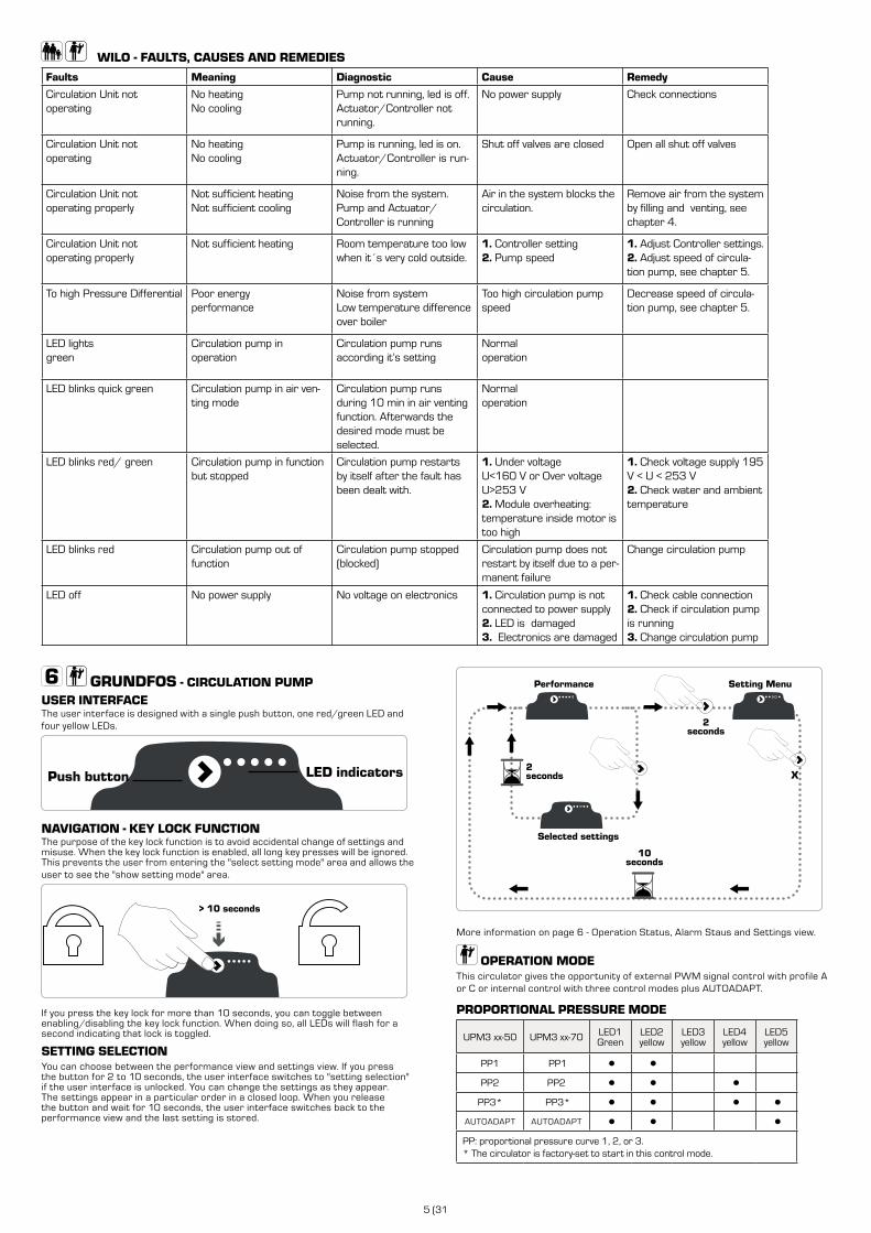
WILO - FAULTS, CAUSES AND REMEDIES
Faults Meaning Diagnostic Cause Remedy
Circulation Unit not operating
No heatingNo cooling
Pump not running, led is off.Actuator/Controller not running.
No power supply Check connections
Circulation Unit not operating
No heatingNo cooling
Pump is running, led is on.Actuator/Controller is run-ning.
Shut off valves are closed Open all shut off valves
Circulation Unit not operating properly
Not sufficient heatingNot sufficient cooling
Noise from the system. Pump and Actuator/Controller is running
Air in the system blocks the circulation.
Remove air from the system by filling and venting, see chapter 4.
Circulation Unit not operating properly
Not sufficient heating Room temperature too low when it´s very cold outside.
1. Controller setting2. Pump speed
1. Adjust Controller settings.2. Adjust speed of circula-tion pump, see chapter 5.
To high Pressure Differential Poor energy performance
Noise from systemLow temperature difference over boiler
Too high circulation pump speed
Decrease speed of circula-tion pump, see chapter 5.
LED lightsgreen
Circulation pump inoperation
Circulation pump runs according it’s setting
Normal operation
LED blinks quick green Circulation pump in air ven-ting mode
Circulation pump runs during 10 min in air venting function. Afterwards the desired mode must be selected.
Normal operation
LED blinks red/ green Circulation pump in functionbut stopped
Circulation pump restarts by itself after the fault has been dealt with.
1. Under voltageU<160 V or Over voltageU>253 V2. Module overheating:temperature inside motor is too high
1. Check voltage supply 195 V < U < 253 V2. Check water and ambient temperature
LED blinks red Circulation pump out offunction
Circulation pump stopped (blocked)
Circulation pump does not restart by itself due to a per-manent failure
Change circulation pump
LED off No power supply No voltage on electronics 1. Circulation pump is not connected to power supply2. LED is damaged3. Electronics are damaged
1. Check cable connection2. Check if circulation pump is running3. Change circulation pump
GRUNDFOS - CIRCULATION PUMP USER INTERFACEThe user interface is designed with a single push button, one red/green LED and four yellow LEDs.
NAVIGATION - KEY LOCK FUNCTIONThe purpose of the key lock function is to avoid accidental change of settings and misuse. When the key lock function is enabled, all long key presses will be ignored. This prevents the user from entering the "select setting mode" area and allows the user to see the "show setting mode" area.
> 10 seconds
If you press the key lock for more than 10 seconds, you can toggle between enabling/disabling the key lock function. When doing so, all LEDs will flash for a second indicating that lock is toggled.
SETTING SELECTIONYou can choose between the performance view and settings view. If you press the button for 2 to 10 seconds, the user interface switches to "setting selection" if the user interface is unlocked. You can change the settings as they appear. The settings appear in a particular order in a closed loop. When you release the button and wait for 10 seconds, the user interface switches back to the performance view and the last setting is stored.
X
Selected settings
2seconds
2seconds
10seconds
Performance Setting Menu
More information on page 6 - Operation Status, Alarm Staus and Settings view.
OPERATION MODEThis circulator gives the opportunity of external PWM signal control with profile A or C or internal control with three control modes plus AUTOADAPT.
PROPORTIONAL PRESSURE MODE
UPM3 xx-50 UPM3 xx-70 LED1Green
LED2yellow
LED3yellow
LED4yellow
LED5yellow
PP1 PP1 ● ●
PP2 PP2 ● ● ●
PP3* PP3* ● ● ● ●
AUTOADAPT AUTOADAPT ● ● ●
PP: proportional pressure curve 1, 2, or 3.* The circulator is factory-set to start in this control mode.
LED indicatorsPush button
6 (31)
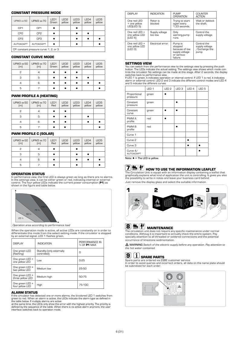
CONSTANT PRESSURE MODE
UPM3 xx-50 UPM3 xx-70 LED1Green
LED2yellow
LED3yellow
LED4yellow
LED5yellow
CP1 CP1 ● ●
CP2 CP2 ● ● ●
CP3 CP3 ● ● ● ●
AUTOADAPT AUTOADAPT ● ● ●
CP: constant pressure curve: 1, 2, or 3.
CONSTANT CURVE MODE
UPM3 xx-50(m)
UPM3 xx-70(m)
LED1Green
LED2yellow
LED3yellow
LED4yellow
LED5yellow
2 4 ● ● ●
3 5 ● ● ● ●
4 6 ● ● ● ● ●
5 7 ● ● ● ●
PWM PROFILE A (HEATING)
UPM3 xx-50(m)
UPM3 xx-70(m)
LED1Red
LED2yellow
LED3yellow
LED4yellow
LED5yellow
2 4 ● ●
3 5 ● ● ●
4 6 ● ● ● ●
5 7 ● ● ●
PWM PROFILE C (SOLAR)
UPM3 xx-50(m)
UPM3 xx-70(m)
LED1Red
LED2yellow
LED3yellow
LED4yellow
LED5yellow
2 4 ● ●
3 5 ● ● ●
4 6 ● ● ● ●
5 7 ● ● ●
OPERATION STATUSIn performance view, the first LED is always green as long as there are no alarms. In the settings view, it can be either green or red, indicating internal or external control. The four yellow LEDs indicate the current power consumption (P1) as shown in the figure and table below.
100 %
75 %
50 %
25 %
Operation area according to performance load
When the operation mode is active, all active LEDs are constantly on in order to differentiate this mode from the select setting mode. If the circulator is stopped by an external signal, LED 1 flashes green.
DISPLAY INDICATION PERFORMANCE IN % OF P1 MAX
One green LED (flashing)
Standby (only externally controlled) 0
One green LED + one yellow LED Low 0-25
One green LED + two yellow LED Medium low 25-50
One green LED + three yellow LED Medium high 50-75
One green LED + four yellow LED High 75-100
ALARM STATUSIf the circulator has detected one or more alarms, the bi-colored LED 1 switches from green to red. When an alarm is active, the LEDs indicate the alarm type as defined in the table below. If multiple alarms are activeat the same time, the LEDs only show the error with the highest priority. The priority is defined by the sequence of the table. When there is no active alarm anymore, the user interface switches back to operation mode.
DISPLAY INDICATION PUMP OPERATION
COUNTER ACTION
One red LED + one yellow LED(LED 5)
Rotor is blocked
Trying to start again every 1.33 seconds.
Wait or deblock the shaft.
One red LED + one yellow LED (LED 4)
Supply voltage too low.
Only warning,pump runs.
Control the supply voltage.
One red LED + one yellow LED (LED 3)
Electrical error. Pump is stopped because of low supply voltage or serious failure.
Control the supply voltage /Exchange the pump.
SETTINGS VIEWYou can switch from the performance view to the settings view by pressing the push button. The LEDs indicate the actual setting. The settings view shows which mode con-trols the circulator. No settings can be made at this stage. After 2 seconds, the display switches back to performance view.If LED 1 is green, it indicates operation or internal control. If LED 1 is red, it indicates alarm or external control. LED 2 and 3 indicate the different control modes and LED 4 and 5 indicate the different curves.
LED 1 LED 2 LED 3 LED 4 LED 5
Proportional pressure
green ●
Constant pressure
green ●
Constant curve
green ● ●
PWM A profile
red ●
PWM B profile
red ●
Curve 1
Curve 2 ●
Curve 3 ● ●
Curve 4/AUTOADAPT
●
Note: ● = The LED is yellow.
HOW TO USE THE INFORMATION LEAFLETThe Circulation Unit is equipt with an information display containing a leaflet that graphically explains what kind of application the unit is controlling. It gives you also the possibility to write in notes and leave your business card behind.
Just remove the display glass and select the suitable information.
MAINTENANCEThe circulation unit does not require any specific maintenance under normal conditions. Althoug it is important to annually check the entire system. Pay specially attention to all threaded or soldered connections and the potential occurrence of limestone sedimentation.
WARNING Switch of the electric supply before any operation. Pay attention to the hot water contained.
SPARE PARTSSpare parts are ordered via ESBE customer service. In order to avoid queries and incorrect orders, all data on the name plate shouldbe submitted for each order.
GXX X00

7 (31
ESBE SYSTEM UNITSSHUNTGRUPP
Serie och funktion • Allmänt/säkerhet
Hydraulisk installation • Elektrisk installation • Igångsättning
Cirkulationspump, WILO
WILO Fel, orsaker och åtgärder
Cirkulationspump, GRUNDFOS
Så här använder du informationsfoldern • Underhåll • Reservdelar
SIDA INNEHÅLL
7
8
9
10
10
11
ALLMÄNT/SÄKERHET
LVD 2014/35/EUEMC 2014/30/EURoHS 2011/65/EUPED 2014/68/EU, article 4.3 Max. driftstryck: PN 6
Den här instruktionshandboken är en viktig komponent i produkten. Läs noggrant instruktionerna och varningarna, för de innehåller viktig information om säker installation, användning och underhåll.
Produkten kan bara användas för cirkulation av vatten och vatten/glykol i värme- eller kylinstallationer.
INSTALLATIONSEXEMPEL
Alla installationsexempel är allmänna beskrivningar.
Tillverkaren ansvarar inte för skador som orsakas av felanvändning eller för att instruktionerna i den här handboken inte har följts.
Enheten måste monteras av en behörig fackman och i enlighet med lokala/regionala lagar. Den här handboken gäller standardprodukter. Det finns andra serier och funktioner.
Vid montering: var uppmärksam på och följ allmän praxis och allmänna säkerhetsnormer för användning av maskiner, trycksatt utrustning och vid höga temperaturer.
För de elektriska komponenter som ingår i produkten finns motsvarande kopior av CE-deklarationerna här nedan.
Ställdon/reglering CirkulationspumpGrundfos
54
UPM3
EC declaration of conformityWe, Grundfos, declare under our sole responsibility that the products GFNJB (UPM variants with user interface) and GFNJC (other UPM3 variants) , to which this declaration relates, are in conformity with these Council directives on the approximation of the laws of the EC member states:
Low Voltage Directive (2006/95/EC)Standards used:
EN 60335-1:2012/AC:2014EN 60335-2-51:2003/A1:2008/A2:2012
EMC Directive (2004/108/EC)Standards used:
EN 55014-1:2006/A1:2009EN 55014-2:1997/A1:2001/A2:2008
Ecodesign Directive (2009/125/EC)Commission Regulation (EC) No 641/2009Commission Regulation (EC) No 622/20012Standards used:
EN 16297-1:2012EN 16297-2:2012EN 16297-3:2012
WarningThe use of this product requires experience with and knowledge of the product. Persons with reduced physical, sensory or mental capabilities must not use this product, unless they are under supervision or have been instructed in the use of the product by a person responsible for their safety. Children must not use or play with this product.
Bjerringbro, 21st of February 2014
Preben Jakobsen Technical Manager - HVAC OEM
GRUNDFOS Holding A/SPoul Due Jensens Vej 7
8850 Bjerringbro, Denmark
Person authorised to compile technical file and empowered to sign the EC declaration of conformity.
VDE certificateThese pumps are certified by VDE.Product code: GFNJB or GFNJCVDE certificate No. 40039416This Marks Approval forms the basis of the CE declaration of conformity and the CE marking by the manufacturer or his agent and proves the conformity with the essential safety requirements of the EC Low Voltage Directive (2006/95/EC) including amendments.
Approvals and certificates
CirkulationspumpWilo
The supplier: Le Fabricant : Der Hersteller:
WILO INTEC 50 Avenue Eugène CASELLA 18700 AUBIGNY SUR NERE FRANCE
certifies that the following pumps, déclare que le type de circulateurs désigné ci-dessous, erklärt, dass die unten genannten Pumpentypen,
WILO YONOS PARA RK WILO YONOS PARA PWM
are meeting the requirements of the European legislation concerning: sont conformes aux dispositions des directives : mit folgenden Richtlinien übereinstimmen:
and the national legislations referring to them. et aux législations nationales les transposant. und entsprechender nationaler Gesetzgebung.
They are also meeting the following European Standards: Elles sont également conformes aux dispositions des normes européennes harmonisées suivantes : Des weiteren entsprechen sie den folgenden harmonisierten europäischen Normen:
NF EN 60.335.1&2.51
If the above mentioned series are technically modified without our approval, this declaration shall no longer be applicable. Si les séries mentionnées ci-dessus sont techniquement modifiées sans notre approbation, cette déclaration ne sera plus applicable. Bei einer mit uns nicht abgestimmten technischen Änderung der oben genannten Bauarten, verliert diese Erklärung ihre Gültigkeit.
M.PERROT
Quality Manager
Aubigny-sur-Nère, the 29th of November 2011
~ "Low Voltage" modified (European law Nr 2006/95/EC) ~ "Basse Tension"modifiée (Directives 2006/95/CE) ~ geänderte "Niederspannung" (Richtlinie 2006/95/EG)
~ "Electromagnetic Compatibility" modified (European law Nr 2004/108/EC) ~ "Compatibilité Electromagnétique" modifiée (Directives 2004/108/CE) ~ geänderte "elektromagnetische Verträglichkeit" (Richtlinie 2004/108/EG)
EC DECLARATION OF CONFORMITY DECLARATION DE CONFORMITE CE
EG KONFORMITÄTSERKLÄRUNG
Vi förbehåller oss rätten att ändra eller förbättra produkten, dess tekniska data och litteratur när som helst och utan föregående meddelande.
SERIE FUNKTION
ESBE GDA111GDA 112
DirektförsörjningGrupp avsedd för direktförsörjning av värme och kyla
ESBE GFA111GFA112
Fast temperaturMed en termostatisk VTA-blandningsventil klar och monterad på shuntgruppen.
ESBE GRC211GRC212
BlandningsfunktionMed regleringen 90C klar och monterad på shuntgruppen. Regleringen har möjlighet att styra pumpen via tidsprogrammet
ESBE GRC111GRC112
BlandningsfunktionMed regleringen CRC klar och monterad på shuntgruppen.
ESBE GRA111GRA112
BlandningsfunktionMed ställdonet ARA klart och monterat på shuntgruppen.
ESBE GBC211GBC212
Bivalent funktionMed regleringen 90C-3 klar och monterad på shuntgruppen. Tillåter simultanstyrning av pump i ytterligare shuntgrupper.
ESBE GBA111GBA112
Bivalent funktionMed ställdonet ARA klart och monterat på shuntgruppen.
ESBE GRC141GRC142
BlandningsfunktionMed regleringen CRD klar och monterad på shuntgruppen.
8 (31)
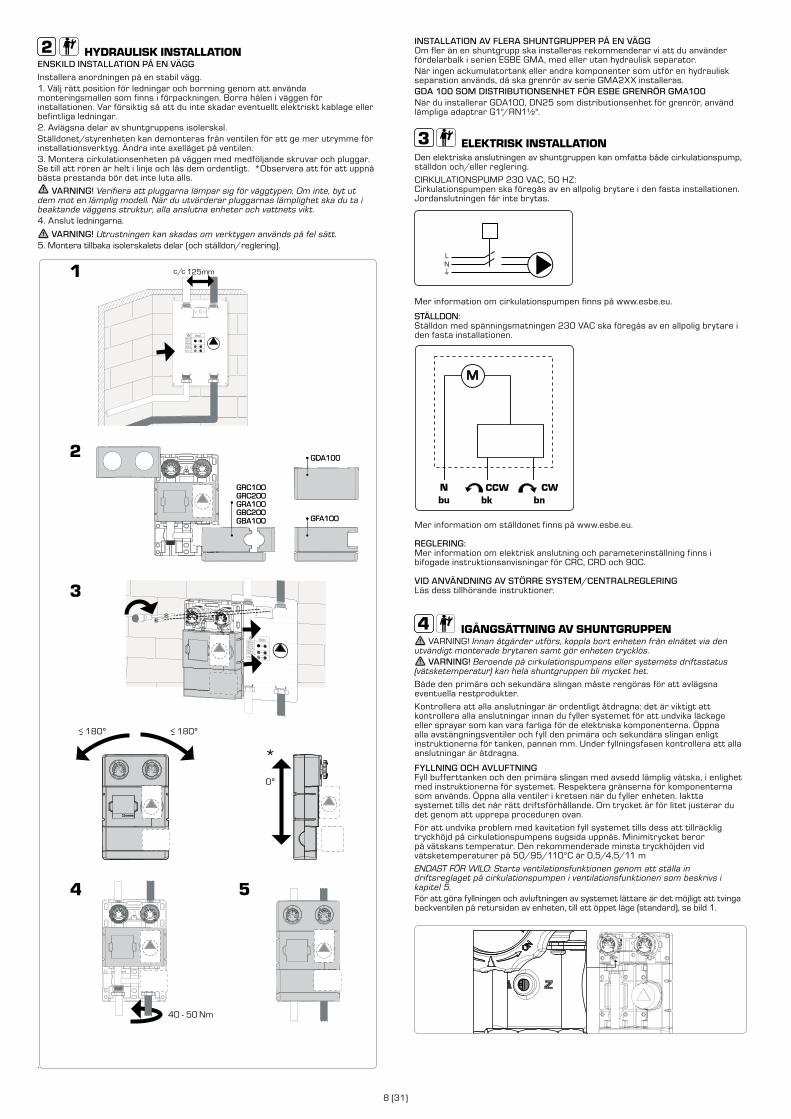
HYDRAULISK INSTALLATIONENSKILD INSTALLATION PÅ EN VÄGGInstallera anordningen på en stabil vägg.1. Välj rätt position för ledningar och borrning genom att använda monteringsmallen som finns i förpackningen. Borra hålen i väggen för installationen. Var försiktig så att du inte skadar eventuellt elektriskt kablage eller befintliga ledningar. 2. Avlägsna delar av shuntgruppens isolerskal.Ställdonet/styrenheten kan demonteras från ventilen för att ge mer utrymme för installationsverktyg. Ändra inte axelläget på ventilen.3. Montera cirkulationsenheten på väggen med medföljande skruvar och pluggar. Se till att rören är helt i linje och lås dem ordentligt. *Observera att för att uppnå bästa prestanda bör det inte luta alls.
VARNING! Verifiera att pluggarna lämpar sig för väggtypen. Om inte, byt ut dem mot en lämplig modell. När du utvärderar pluggarnas lämplighet ska du ta i beaktande väggens struktur, alla anslutna enheter och vattnets vikt. 4. Anslut ledningarna.
VARNING! Utrustningen kan skadas om verktygen används på fel sätt.5. Montera tillbaka isolerskalets delar (och ställdon/reglering).
.
GDA100
GFA100
GRC100GRC200GRA100GBC200GBA100
180º>180º>
0º
GDA100
GFA100
40 - 50 Nm
GRC100GRC200GRA100GBC200GBA100
*
INSTALLATION AV FLERA SHUNTGRUPPER PÅ EN VÄGGOm fler än en shuntgrupp ska installeras rekommenderar vi att du använder fördelarbalk i serien ESBE GMA, med eller utan hydraulisk separator. När ingen ackumulatortank eller andra komponenter som utför en hydraulisk separation används, då ska grenrör av serie GMA2XX installeras. GDA 100 SOM DISTRIBUTIONSENHET FÖR ESBE GRENRÖR GMA100När du installerar GDA100, DN25 som distributionsenhet för grenrör, använd lämpliga adaptrar G1"/RN1½".
ELEKTRISK INSTALLATIONDen elektriska anslutningen av shuntgruppen kan omfatta både cirkulationspump, ställdon och/eller reglering.
CIRKULATIONSPUMP 230 VAC, 50 HZ:Cirkulationspumpen ska föregås av en allpolig brytare i den fasta installationen. Jordanslutningen får inte brytas.
LN
Mer information om cirkulationspumpen finns på www.esbe.eu.
STÄLLDON:Ställdon med spänningsmatningen 230 VAC ska föregås av en allpolig brytare i den fasta installationen.
M
Mer information om ställdonet finns på www.esbe.eu.
REGLERING:Mer information om elektrisk anslutning och parameterinställning finns i bifogade instruktionsanvisningar för CRC, CRD och 90C.
VID ANVÄNDNING AV STÖRRE SYSTEM/CENTRALREGLERING Läs dess tillhörande instruktioner.
IGÅNGSÄTTNING AV SHUNTGRUPPEN VARNING! Innan åtgärder utförs, koppla bort enheten från elnätet via den
utvändigt monterade brytaren samt gör enheten trycklös. VARNING! Beroende på cirkulationspumpens eller systemets driftsstatus
(vätsketemperatur) kan hela shuntgruppen bli mycket het.
Både den primära och sekundära slingan måste rengöras för att avlägsna eventuella restprodukter.
Kontrollera att alla anslutningar är ordentligt åtdragna: det är viktigt att kontrollera alla anslutningar innan du fyller systemet för att undvika läckage eller sprayar som kan vara farliga för de elektriska komponenterna. Öppna alla avstängningsventiler och fyll den primära och sekundära slingan enligt instruktionerna för tanken, pannan mm. Under fyllningsfasen kontrollera att alla anslutningar är åtdragna.
FYLLNING OCH AVLUFTNINGFyll bufferttanken och den primära slingan med avsedd lämplig vätska, i enlighet med instruktionerna för systemet. Respektera gränserna för komponenterna som används. Öppna alla ventiler i kretsen när du fyller enheten. Iaktta systemet tills det når rätt driftsförhållande. Om trycket är för litet justerar du det genom att upprepa proceduren ovan.
För att undvika problem med kavitation fyll systemet tills dess att tillräcklig tryckhöjd på cirkulationspumpens sugsida uppnås. Minimitrycket beror på vätskans temperatur. Den rekommenderade minsta tryckhöjden vid vätsketemperaturer på 50/95/110°C är 0,5/4,5/11 m
ENDAST FÖR WILO: Starta ventilationsfunktionen genom att ställa in driftsreglaget på cirkulationspumpen i ventilationsfunktionen som beskrivs i kapitel 5. För att göra fyllningen och avluftningen av systemet lättare är det möjligt att tvinga backventilen på retursidan av enheten, till ett öppet läge (standard), se bild 1.
9 (31
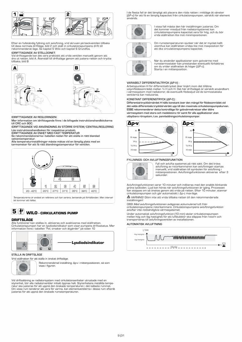
I de flesta fall är det lämpligt att placera den röda ratten i mittläge åt vänster (ΔP-v) för att få en lämplig kapacitet från cirkulationspumpen, särskilt när element används.
I vissa fall måste den här inställningen justeras: Om det kommer missljud från radiatorsystemet kan cirkulationspumpens kapacitet vara för hög, och du bör vrida ställratten lite mot minimipositionen.
Om rumstemperaturen sjunker när det är mycket kallt utomhus kan ställratten vridas lite mot maxposition för att öka circulationspumpens kapacitet.
När du använder applikationer som golvvärme med rumstermostater kan prestandan eventuellt förbättras om du vrider ställratten åt höger (ΔP-c). Starta i en mittenposition.
VARIABELT DIFFERENTIALTRYCK (ΔP-V) :Arbetspunkten H för differentialtrycket ökar linjärt inom det tillåtna volymflödesområdet mellan ½ H och H. Det här driftsläget är särskilt användbart i värmesystem med radiatorer, då eventuellt flödesljud vid de termostatiska ventilerna kan reduceras.
KONSTANT DIFFERENSTRYCK (ΔP-C) :Differential-tryckbörvärdet H hålls konstant över den mängd för flödesområdet vid det valda differentiala tryckbörvärdet upp till den maximala cirkulationspumpskurvan. ESBE rekommenderar detta kontrolläge för golvvärmekretsar eller äldre värmesystem med stora och medelstora rör samt för alla applikationer utan utbytbara rörsystem, t.ex. pannladdningscirkulationspumpar.
H
H max
H s
½ H s
H min
Q
H
H max
H s
½ H s
H min
Q
FYLLNINGS- OCH AVLUFTNINGSFUNKTIONFyll och avlufta systemet på rätt sätt. Om det krävs avluftning av rotorkammaren kan avluftningen startas manuellt, vrid ställratten till symbolen för avluftning i mittenpositionen. Avluftningsfunktionen aktiveras efter 3 sekunder.
Avluftningsfunktionen varar 10 minuter och indikeras med den snabbt blinkande gröna lysdioden. Ljud kan höras när avluftningsfunktionen är igång. Processen kan stoppas om så önskas genom att vrida på ratten. Efter 10 minuter, stannar cirkulationspumpen och går automatiskt i Δp-c max-läge.
VARNING! Glöm inte att vrida tillbaka ratten till den rekommenderade inställningen!
OBS! Med avluftningsfunktionen avlägsnas ackumulerad luft från cirkulationspumpens rotorkammare. Cirkulationspumpens avluftningsfunktion avluftar inte nödvändigtvis värmesystemet.
Under automatisk avluftningsfunktion (10 min) växlar cirkulationspumpen mellan hög och låg hastighet för att luftbubblor ska släppas från rotorn och transporteras till avluftningsventilen av installationen.
AUTOMATISK AVLUFTNING
high speed
low speed
l/min
high speed
t
low speed
10 min
Hög hastighet
Låg hastighet
Efter en fullständig fyllning och avluftning, vrid skruven på backventilen tillbaka till dess normala driftläge, bild 2 och ställ in cirkulationspumpens drift till rekommenderat läge. Se kapitel 5 Wilo och kapitel 6 Grundfos.
IDRIFTTAGANDE AV STÄLLDONET:Vid drifttagande kan det vara praktiskt att vrida ventilen manuellt genom att dra ut ratten, bild A. Återställ till driftsläge genom att justera ratten och trycka tillbaka, bild B
1
IDRIFTTAGANDE AV REGLERINGEN:Mer information om idrifttagande finns i de bifogade instruktionshandböckerna till CRC och 90C.IDRIFTTAGANDE VID ANVÄNDNING AV STÖRRE SYSTEM/CENTRALREGLERINGLäs instruktionshandboken för respektive produkt.IDRIFTTAGANDE AV ENHET MED FAST TEMPERATURSe rekommendationerna i tabellen nedan för att ställa in rätt blandad vattentemperatur. Alla temperaturinställningar måste mätas vid en lämplig plats med en termometer för att få rätt blandningstemperatur för ventilen.
20 - 43°C 20°C 27°C 31°C 35°C 39°C 43°C
Temperaturerna är endast en referens och kan variera, beroende på förhållanden. Men interval-let kommer att hållas.
WILO - CIRKULATIONS PUMP
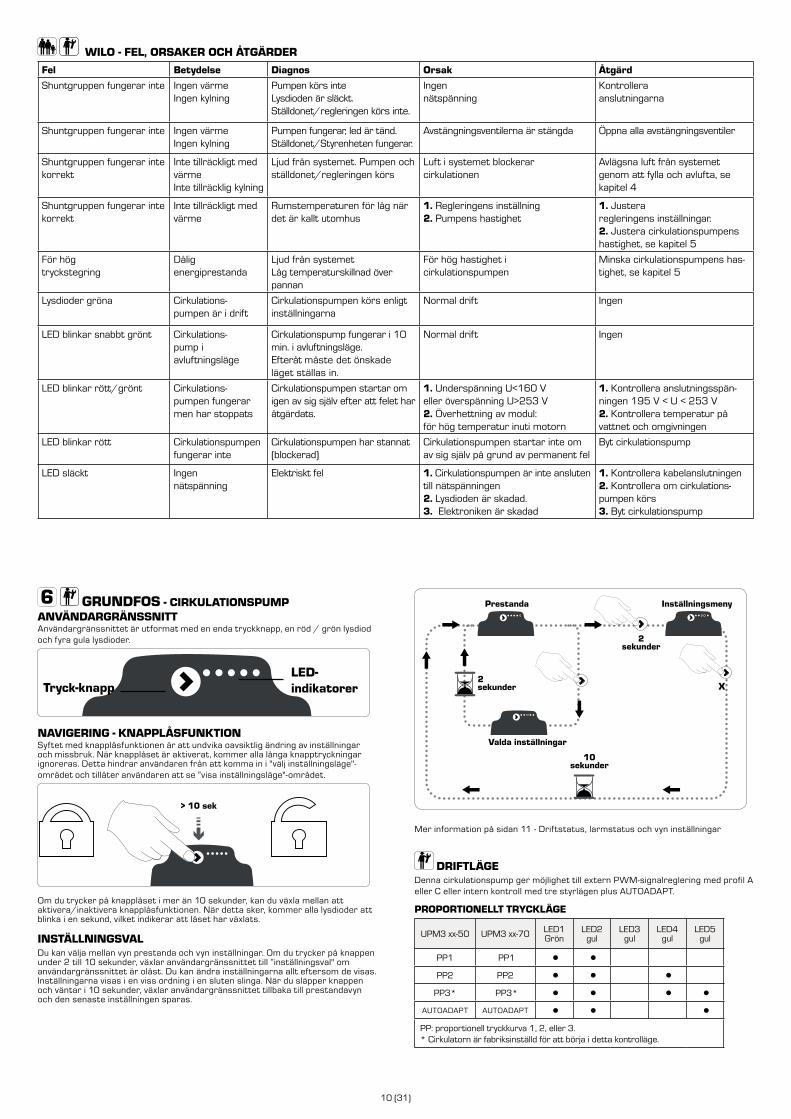
DRIFTSLÄGEAlla funktioner kan ställas in, aktiveras och avaktiveras med ställratten. Cirkulationspumpen har en lysdiodsindikator som visar pumpens driftsstatus. Mer information finns i tabellen ”Fel, orsaker och åtgärder” på sidan 10
Lysdiodsindikator
STÄLLA IN DRIFTSLÄGEVrid ställratten för att ställa in önskat driftsläge.
Rekommenderad inställning: Δp-v i mittenpositionen, så som visas i figuren.
Vid driftsättning av radiatorsystem med cirkulationsenheter utrustade med en styrenhet, bör alla radiatorventiler initialt öppnas helt. Styrenhetens inställda tempe-ratur ska justeras för att uppnå den önskade temperaturen i det kallaste rummet. Om vissa rum tenderar att vara för varma, kan elementventilerna i dessa rum efteråt justeras för att uppnå den önskade rumstemperaturen.
10 (31)
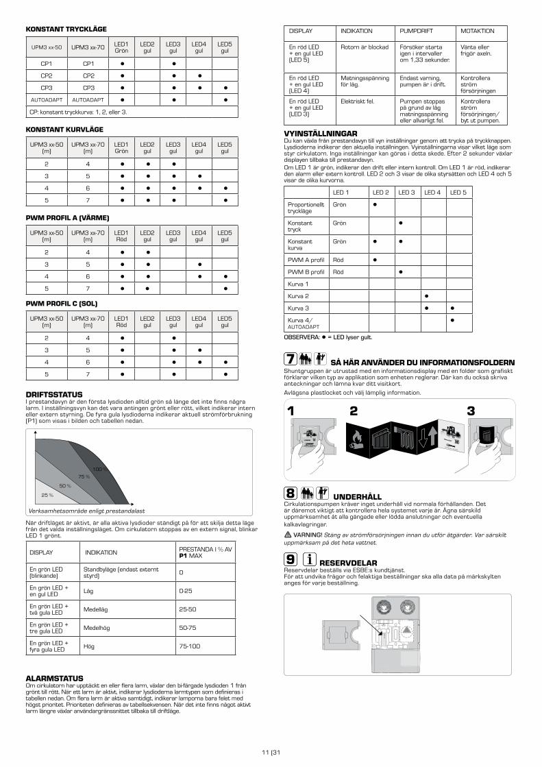
GRUNDFOS - CIRKULATIONSPUMP ANVÄNDARGRÄNSSNITTAnvändargränssnittet är utformat med en enda tryckknapp, en röd / grön lysdiod och fyra gula lysdioder.
NAVIGERING - KNAPPLÅSFUNKTIONSyftet med knapplåsfunktionen är att undvika oavsiktlig ändring av inställningar och missbruk. När knapplåset är aktiverat, kommer alla långa knapptryckningar ignoreras. Detta hindrar användaren från att komma in i "välj inställningsläge"-området och tillåter användaren att se ”visa inställningsläge"-området.
> 10 sek
Om du trycker på knapplåset i mer än 10 sekunder, kan du växla mellan att aktivera/inaktivera knapplåsfunktionen. När detta sker, kommer alla lysdioder att blinka i en sekund, vilket indikerar att låset har växlats.
INSTÄLLNINGSVALDu kan välja mellan vyn prestanda och vyn inställningar. Om du trycker på knappen under 2 till 10 sekunder, växlar användargränssnittet till ”inställningsval" om användargränssnittet är olåst. Du kan ändra inställningarna allt eftersom de visas. Inställningarna visas i en viss ordning i en sluten slinga. När du släpper knappen och väntar i 10 sekunder, växlar användargränssnittet tillbaka till prestandavyn och den senaste inställningen sparas.
WILO - FEL, ORSAKER OCH ÅTGÄRDER
Fel Betydelse Diagnos Orsak Åtgärd
Shuntgruppen fungerar inte Ingen värmeIngen kylning
Pumpen körs inteLysdioden är släckt.Ställdonet/regleringen körs inte.
Ingen nätspänning
Kontrollera anslutningarna
Shuntgruppen fungerar inte Ingen värmeIngen kylning
Pumpen fungerar, led är tänd.Ställdonet/Styrenheten fungerar.
Avstängningsventilerna är stängda Öppna alla avstängningsventiler
Shuntgruppen fungerar inte korrekt
Inte tillräckligt med värmeInte tillräcklig kylning
Ljud från systemet. Pumpen och ställdonet/regleringen körs
Luft i systemet blockerar cirkulationen
Avlägsna luft från systemet genom att fylla och avlufta, se kapitel 4
Shuntgruppen fungerar inte korrekt
Inte tillräckligt med värme
Rumstemperaturen för låg när det är kallt utomhus
1. Regleringens inställning2. Pumpens hastighet
1. Justera regleringens inställningar.2. Justera cirkulationspumpens hastighet, se kapitel 5
För hög tryckstegring
Dålig energiprestanda
Ljud från systemetLåg temperaturskillnad över pannan
För hög hastighet i cirkulationspumpen
Minska cirkulationspumpens has-tighet, se kapitel 5
Lysdioder gröna Cirkulations-pumpen är i drift
Cirkulationspumpen körs enligt inställningarna
Normal drift Ingen
LED blinkar snabbt grönt Cirkulations-pump i avluftningsläge
Cirkulationspump fungerar i 10 min. i avluftningsläge. Efteråt måste det önskade läget ställas in.
Normal drift Ingen
LED blinkar rött/grönt Cirkulations-pumpen fungerar men har stoppats
Cirkulationspumpen startar om igen av sig själv efter att felet har åtgärdats.
1. Underspänning U<160 Veller överspänning U>253 V2. Överhettning av modul:för hög temperatur inuti motorn
1. Kontrollera anslutningsspän-ningen 195 V < U < 253 V2. Kontrollera temperatur på vattnet och omgivningen
LED blinkar rött Cirkulationspumpen fungerar inte
Cirkulationspumpen har stannat (blockerad)
Cirkulationspumpen startar inte om av sig själv på grund av permanent fel
Byt cirkulationspump
LED släckt Ingen nätspänning
Elektriskt fel 1. Cirkulationspumpen är inte ansluten till nätspänningen2. Lysdioden är skadad.3. Elektroniken är skadad
1. Kontrollera kabelanslutningen2. Kontrollera om cirkulations-pumpen körs3. Byt cirkulationspump
X
Valda inställningar
2sekunder
2sekunder
10sekunder
Prestanda Inställningsmeny
Mer information på sidan 11 - Driftstatus, larmstatus och vyn inställningar
DRIFTLÄGEDenna cirkulationspump ger möjlighet till extern PWM-signalreglering med profil A eller C eller intern kontroll med tre styrlägen plus AUTOADAPT.
PROPORTIONELLT TRYCKLÄGE
UPM3 xx-50 UPM3 xx-70 LED1Grön
LED2gul
LED3gul
LED4gul
LED5gul
PP1 PP1 ● ●
PP2 PP2 ● ● ●
PP3* PP3* ● ● ● ●
AUTOADAPT AUTOADAPT ● ● ●
PP: proportionell tryckkurva 1, 2, eller 3.* Cirkulatorn är fabriksinställd för att börja i detta kontrolläge.
LED-indikatorerTryck-knapp
11 (31
KONSTANT TRYCKLÄGE
UPM3 xx-50 UPM3 xx-70 LED1Grön
LED2gul
LED3gul
LED4gul
LED5gul
CP1 CP1 ● ●
CP2 CP2 ● ● ●
CP3 CP3 ● ● ● ●
AUTOADAPT AUTOADAPT ● ● ●
CP: konstant tryckkurva: 1, 2, eller 3.
KONSTANT KURVLÄGE
UPM3 xx-50(m)
UPM3 xx-70(m)
LED1Grön
LED2gul
LED3gul
LED4gul
LED5gul
2 4 ● ● ●
3 5 ● ● ● ●
4 6 ● ● ● ● ●
5 7 ● ● ● ●
PWM PROFIL A (VÄRME)
UPM3 xx-50(m)
UPM3 xx-70(m)
LED1Röd
LED2gul
LED3gul
LED4gul
LED5gul
2 4 ● ●
3 5 ● ● ●
4 6 ● ● ● ●
5 7 ● ● ●
PWM PROFIL C (SOL)
UPM3 xx-50(m)
UPM3 xx-70(m)
LED1Röd
LED2gul
LED3gul
LED4gul
LED5gul
2 4 ● ●
3 5 ● ● ●
4 6 ● ● ● ●
5 7 ● ● ●
DRIFTSSTATUSI prestandavyn är den första lysdioden alltid grön så länge det inte finns några larm. I inställningsvyn kan det vara antingen grönt eller rött, vilket indikerar intern eller extern styrning. De fyra gula lysdioderna indikerar aktuell strömförbrukning (P1) som visas i bilden och tabellen nedan.
100 %
75 %
50 %
25 %
Verksamhetsområde enligt prestandalast
När driftläget är aktivt, är alla aktiva lysdioder ständigt på för att skilja detta läge från det valda inställningsläget. Om cirkulatorn stoppas av en extern signal, blinkar LED 1 grönt.
DISPLAY INDIKATION PRESTANDA I % AV P1 MAX
En grön LED (blinkande)
Standbyläge (endast externt styrd) 0
En grön LED + en gul LED Låg 0-25
En grön LED + två gula LED Medellåg 25-50
En grön LED + tre gula LED Medelhög 50-75
En grön LED + fyra gula LED Hög 75-100
ALARMSTATUSOm cirkulatorn har upptäckt en eller flera larm, växlar den bi-färgade lysdioden 1 från grönt till rött. När ett larm är aktivt, indikerar lysdioderna larmtypen som definieras i tabellen nedan. Om flera larm är aktiva samtidigt, indikerar lamporna bara felet med högst prioritet. Prioriteten definieras av tabellsekvensen. När det inte finns något aktivt larm längre växlar användargränssnittet tillbaka till driftläge.
DISPLAY INDIKATION PUMPDRIFT MOTAKTION
En röd LED + en gul LED (LED 5)
Rotorn är blockad Försöker starta igen i intervaller om 1,33 sekunder.
Vänta eller frigör axeln.
En röd LED + en gul LED (LED 4)
Matningsspänning för låg.
Endast varning, pumpen är i drift.
Kontrollera ström försörjningen
En röd LED + en gul LED (LED 3)
Elektriskt fel. Pumpen stoppas på grund av låg matningsspänning eller allvarligt fel.
Kontrollera ström försörjningen/byt ut pumpen.
VYINSTÄLLNINGARDu kan växla från prestandavyn till vyn inställningar genom att trycka på tryckknappen. Lysdioderna indikerar den aktuella inställningen. Vyinställningarna visar vilket läge som styr cirkulatorn. Inga inställningar kan göras i detta skede. Efter 2 sekunder växlar displayen tillbaka till prestandavyn.Om LED 1 är grön, indikerar den drift eller intern kontroll. Om LED 1 är röd, indikerar den alarm eller extern kontroll. LED 2 och 3 visar de olika styrsätten och LED 4 och 5 visar de olika kurvorna.
LED 1 LED 2 LED 3 LED 4 LED 5
Proportionellt tryckläge
Grön ●
Konstant tryck
Grön ●
Konstant kurva
Grön ● ●
PWM A profil Röd ●
PWM B profil Röd ●
Kurva 1
Kurva 2 ●
Kurva 3 ● ●
Kurva 4/AUTOADAPT
●
OBSERVERA: ● = LED lyser gult.
SÅ HÄR ANVÄNDER DU INFORMATIONSFOLDERNShuntgruppen är utrustad med en informationsdisplay med en folder som grafiskt förklarar vilken typ av applikation som enheten reglerar. Där kan du också skriva anteckningar och lämna kvar ditt visitkort.
Avlägsna plastlocket och välj lämplig information.
UNDERHÅLLCirkulationspumpen kräver inget underhåll vid normala förhållanden. Det är däremot viktigt att kontrollera hela systemet varje år. Ägna särskild uppmärksamhet åt alla gängade eller lödda anslutningar och eventuella kalkavlagringar.
VARNING! Stäng av strömförsörjningen innan du utför åtgärder. Var särskilt uppmärksam på det heta vattnet.
RESERVDELARReservdelar beställs via ESBE:s kundtjänst. För att undvika frågor och felaktiga beställningar ska alla data på märkskylten anges för varje beställning.
GXX X00
12 (31)
ESBE BAUGRUPPENPUMPENGRUPPE
Serie und Funktion • Allgemein/Sicherheit
Montage • Elektroinstallation
Inbetriebnahme • Pumpengruppe, Betriebsart WILO
WILO Fehler, Ursachen und Abhilfemaßnahmen
Pumpengruppe, Betriebsart GRUNDFOS
Umgang mit dem Informationsblatt • Wartung • Ersatzteile
SEITE INHALT
12
13
14
15
15
16DE
ALLGEMEIN/SICHERHEIT
LVD 2014/35/EUEMC 2014/30/EURoHS 2011/65/EUPED 2014/68/EU, article 4.3 Max. Betriebsdruck: PN 6
Dieses Handbuch ist ein wesentlicher Bestandteil des Produkts. Lesen Sie die Anweisungen und Warnhinweise sorgfältig durch, da sie wichtige Informationen über sichere Installation, Handhabung und Wartung enthalten.
Dieses Produkt darf nur in geschlossenen Umlauf Heiz- oder Kühlkreisläufen (Wasser oder Wasser-Glykol-Gemisch) verwendet werden.
EINBAUBEISPIEL
Alle Schalt- und Schaubilder sind lediglich allgemeine Darstellungen.
Der Hersteller übernimmt keine Verantwortung für Schäden, die sich aus nicht ordnungsgemäßem Gebrauch oder Nichtbeachten der Anweisungen in diesem Handbuch ergeben.
Die Montage der Einheit muss von geeignetem Fachpersonal unter Beachtung lokaler und regionaler Bestimmungen und Vorschriften erfolgen. Dieses Handbuch beschreibt Standardprodukte. Abweichende Serien oder Funktionen sind erhältlich.
Gehen Sie bei der Montage konzentriert und umsichtig vor, beachten Sie allgemein übliche Arbeitsmethoden und allgemeine Sicherheitsnormen für den Umgang mit Maschinen, Druckanlagen und hohen Temperaturen.
Für die elektrischen Komponenten dieses Produkts gelten die Kopien der entsprechenden CE-Erklärungen. Sie sind ein wesentlicher Bestandteil dieses Handbuchs.
Stellmotor / Stellmotorregler UmwälzpumpeGrundfos
54
UPM3
EC declaration of conformityWe, Grundfos, declare under our sole responsibility that the products GFNJB (UPM variants with user interface) and GFNJC (other UPM3 variants) , to which this declaration relates, are in conformity with these Council directives on the approximation of the laws of the EC member states:
Low Voltage Directive (2006/95/EC)Standards used:
EN 60335-1:2012/AC:2014EN 60335-2-51:2003/A1:2008/A2:2012
EMC Directive (2004/108/EC)Standards used:
EN 55014-1:2006/A1:2009EN 55014-2:1997/A1:2001/A2:2008
Ecodesign Directive (2009/125/EC)Commission Regulation (EC) No 641/2009Commission Regulation (EC) No 622/20012Standards used:
EN 16297-1:2012EN 16297-2:2012EN 16297-3:2012
WarningThe use of this product requires experience with and knowledge of the product. Persons with reduced physical, sensory or mental capabilities must not use this product, unless they are under supervision or have been instructed in the use of the product by a person responsible for their safety. Children must not use or play with this product.
Bjerringbro, 21st of February 2014
Preben Jakobsen Technical Manager - HVAC OEM
GRUNDFOS Holding A/SPoul Due Jensens Vej 7
8850 Bjerringbro, Denmark
Person authorised to compile technical file and empowered to sign the EC declaration of conformity.
VDE certificateThese pumps are certified by VDE.Product code: GFNJB or GFNJCVDE certificate No. 40039416This Marks Approval forms the basis of the CE declaration of conformity and the CE marking by the manufacturer or his agent and proves the conformity with the essential safety requirements of the EC Low Voltage Directive (2006/95/EC) including amendments.
Approvals and certificates
UmwälzpumpeWilo
The supplier: Le Fabricant : Der Hersteller:
WILO INTEC 50 Avenue Eugène CASELLA 18700 AUBIGNY SUR NERE FRANCE
certifies that the following pumps, déclare que le type de circulateurs désigné ci-dessous, erklärt, dass die unten genannten Pumpentypen,
WILO YONOS PARA RK WILO YONOS PARA PWM
are meeting the requirements of the European legislation concerning: sont conformes aux dispositions des directives : mit folgenden Richtlinien übereinstimmen:
and the national legislations referring to them. et aux législations nationales les transposant. und entsprechender nationaler Gesetzgebung.
They are also meeting the following European Standards: Elles sont également conformes aux dispositions des normes européennes harmonisées suivantes : Des weiteren entsprechen sie den folgenden harmonisierten europäischen Normen:
NF EN 60.335.1&2.51
If the above mentioned series are technically modified without our approval, this declaration shall no longer be applicable. Si les séries mentionnées ci-dessus sont techniquement modifiées sans notre approbation, cette déclaration ne sera plus applicable. Bei einer mit uns nicht abgestimmten technischen Änderung der oben genannten Bauarten, verliert diese Erklärung ihre Gültigkeit.
M.PERROT
Quality Manager
Aubigny-sur-Nère, the 29th of November 2011
~ "Low Voltage" modified (European law Nr 2006/95/EC) ~ "Basse Tension"modifiée (Directives 2006/95/CE) ~ geänderte "Niederspannung" (Richtlinie 2006/95/EG)
~ "Electromagnetic Compatibility" modified (European law Nr 2004/108/EC) ~ "Compatibilité Electromagnétique" modifiée (Directives 2004/108/CE) ~ geänderte "elektromagnetische Verträglichkeit" (Richtlinie 2004/108/EG)
EC DECLARATION OF CONFORMITY DECLARATION DE CONFORMITE CE
EG KONFORMITÄTSERKLÄRUNG
Wir behalten uns das Recht vor, Veränderungen und Verbesserungen am Produkt, seinen technischen Daten und der Produktliteratur jederzeit und ohne vorherige Ankündigung vorzunehmen.
SERIE FUNKTION
ESBE GDA111GDA 112
DirektversorgungDirektversorgung von Heiz- oder Kühlsystemen
ESBE GFA111GFA112
Konstante Vorlauftemperatur(thermischer Mischautomat) mit thermischem Mischautomaten VTA572
ESBE GRC211GRC212
Witterungsgeführte Vorlauftemperatur (3-Wege)mit Mischer der Serie VRG und witterungsgeführtem Stellmotorregler Serie 90C-1 mit individuell einstellbarem Zeitprogramm
ESBE GRC111GRC112
Witterungsgeführte Vorlauftemperatur (3-Wege)mit Mischer der Serie VRG und witterungsgeführtem Stellmotorregler Serie CRC
ESBE GRA111GRA112
Gemischte Vorlauftemperatur (3-Wege)mit Mischer der Serie VRG und 3-Punkt Stellmotor Serie ARA661
ESBE GBC211GBC212
Witterunsgeführte Vorlauftemperatur(Bivalent- Mischer) mit Mischer der Serie VRG und witterungsgeführtem Stellmotorregler Serie 90C-3 mit individuell einstellbarem Zeitprogramm und der Möglichkeit, die Umwälzpumpe eines Direktheizkreises anzusteuern
ESBE GBA111GBA112
Gemischte Vorlauftemperatur(Bivalent-Mischer) mit Mischer der Serie VRB und 3-Punkt Stellmotor Serie ARA661
ESBE GRC141GRC142
Witterungsgeführte Vorlauftemperatur (3-Wege)mit Mischer der Serie VRG und witterungsgeführtem Stellmotorregler Serie CRD.
13 (31
MONTAGEWANDINSTALLATION, EINZELNE PUMPENGRUPPE 1. Wählen Sie anhand der mitgelieferten Montageschablone die richtige Lage für Leitungen und Verschraubung aus und markieren Sie die Bohrlöcher. Achten Sie darauf, dass Sie beim Bohren keine elektrischen Leitungen oder bestehende Rohre beschädigen.2. Wenn nötig, entfernen Sie zur leichteren Montage Teile der Isolierung. Der Stellmotor/Stellmotorregler kann bei Bedarf ebenfalls demontiert werden. Achten Sie in diesem Fall darauf, dass die Position der Mischerachse dabei nicht verändert wird.3. Befestigen Sie die Pumpengruppe mit Hilfe der beiliegenden Dübel und Schrauben. Achten Sie darauf, dass die Pumpengruppe vor dem endgültigen Festziehen der Schrauben vollständig ausgerichtet ist.
WARNUNG! Prüfen Sie vor der Montage, ob die mitgelieferten Schrauben und Dübel für Ihre Montagesituation geeignet sind. Um die Eignung einzuschätzen, berücksichtigen Sie den Wandaufbau sowie das Gewicht der gesamten Baugruppe und das des Wassers. Verwenden Sie bei Bedarf spezielles Befestigungsmaterial. 4. Verbinden Sie die Rohrleitungen. Beachten Sie dabei die Installationsvorschriften des Rohrherstellers.
WARNUNG! Nicht ordnungsgemäßer Gebrauch von Werkzeug kann zuBeschädigungen von einzelnen Bauteilen führen.
5. Bringen Sie die Teile der Isolierung (sowie Stellmotor / Stellmotorregler) wieder an.
GDA100
GFA100
GRC100GRC200GRA100GBC200GBA100
180º>180º>
0º
GDA100
GFA100
40 - 50 Nm
GRC100GRC200GRA100GBC200GBA100
*
WANDINSTALLATION, MEHRERE PUMPENGRUPPEENWerden mehrere Pumpengruppen montiert, empfehlen wir die Verwendung von Verteilerbalken der Serie ESBE GMA. Diese können separat bestellt werden und sind für zwei oder drei Pumpengruppen sowie mit oder ohne integrierte hydraulische Weiche erhältlich. Für weitere Informationen beachten Sie bitte die Produktinformationen für Verteilerbalken.
GDA100 ZUM VERSORGEN DES VERTEILERBALKENS GMA100Wird die Pumpengruppe GDA100 zum Versorgen des VerteilerbalkensGMA100 genutzt, verwenden Sie geeignete Übergänge G1"/RN1½".Zusätzlich ist bei der Pumpengruppe der Vor- und Rücklauf zu tauschen.Entfernen Sie hierzu die komplette Isolation.
ELEKTROINSTALLATIONDer Elektroanschluss der Pumpengruppe hängt sowohl von der Umwälzpumpe als auch vom Stellmotor und/oder Regler ab.
UMWÄLZPUMPE 230 VAC, 50HZ:Der Umwälzpumpe muss ein allpoliger Unterbrecherkontakt fest vorgeschaltet sein. Der Erdungsanschluss darf nicht beschädigt sein.
LN
Weitere Informationen zur Umwälzpumpe finden Sie unter www.esbe.eu
STELLMOTOR:Stellmotoren mit einer Stromversorgung von 230 VAC muss ein allpoliger Unterbrecherkontakt fest vorgeschaltet sein.
M
Weitere Informationen zum Stellmotor finden Sie unter www.esbe.eu
STELLMOTORREGLER:Für weitere Informationen bezüglich Elektroanschluss und Parametereinstellungen beachten Sie bitte die mitgelieferten Handbücher für CRC, CRD und 90C.
BEI EINBAU IN GRÖSSERE SYSTEME / ZENTRALSTEUERUNG: Beachten Sie die Handbücher aller eingesetzten Produkte.
INBETRIEBNAHME DER PUMPENGRUPPE
WARNUNG! Bevor Eingriffe jeglicher Art vorgenommen werden, muss die Stromversorgung über den außen angebrachten Schalter getrennt und die Anlage drucklos gemacht werden.
WARNUNG! Abhängig vom Betriebszustand der Umwälzpumpe oder des Systems (Temperatur der Flüssigkeit) kann die gesamte Pumpengruppe sehr heiß werden.
Um Schäden an der Pumpengruppe durch Schmutzreste zu vermeiden, ist das komplette System gemäß den gültigen Vorschriften und technischen Regeln sorgfältig zu spülen. Überprüfen Sie, ob alle Anschlüsse ordnungsgemäß festgezogen sind, bevor das System befüllt wird. Austretendes Wasser könnte elektrische Komponenten beschädigen und zu lebensgefährlichen Situationen führen!
BEFÜLLEN UND ENTLÜFTENÖffnen Sie alle Absperrventile und füllen Sie langsam den Heiz- / Kühlkreis gemäß den Anweisungen aller Komponenten, wie beispielsweise Heizkessel oder Pufferspeicher. Während der Befüllungsphase prüfen Sie erneut, ob alle Anschlüsse dicht sind.Befüllen Sie das System nur mit geeigneter Flüssigkeit gemäß den Anweisungen. Beachten Sie dabei die Grenzwerte der eingesetzten Komponenten. Öffnen Sie während des Befüllvorgangs alle Entlüftungseinrichtungen. Beobachten Sie das System, bis alle Luft entwichen ist und der ordnungsgemäße Betriebsdruck erreicht ist.
Um Probleme durch Kavitation zu vermeiden, füllen Sie das System soweit auf, dass Sie auf der Ansaugseite der Umwälzpumpe einen ausreichenden Betriebsdruck erhalten. Der benötigte Mindestdruck ist abhängig von der Temperatur der Flüssigkeit. Der empfohlene minimale Betriebsdruck bei Flüssigkeitstemperaturen von 50/95/110°C beträgt entsprechend 0,5/4,5/11 m Wassersäule (entspricht 0,05 / 0.45 / 1.10 bar).
NUR FÜR WILO: Wählen Sie am Betriebsknopf der Pumpe die Entlüftungsfunktion, siehe Kapitel 5.
m/m
14 (31)
Bei der Inbetriebnahme von Heizungssystemen mit Pumpengruppen, die mit einem Regler ausgestattet sind, müssen zunächst alle Heizungsventile voll geöffnet sein. Die Einstelltemperatur des Reglers ist so anzupassen, dass im kältesten Raum die gewünschte Temperatur erreicht wird. Wird in manchen Räumen die Temperatur zu hoch, können die Heizungsventile anschließend eingestellt werden, sodass die gewünschte Temperatur erreicht wird.Hinweis: Die Umwälzpumpe lässt sich an verschiedenste Installationen anpassen, ein hydraulischer Abgleich ist dennoch in jedem Fall notwendig. Bei den meisten Installationen ist das Voreinstellen eines variablen Differenzdrucks im mittleren Bereich vorteilhaft (linke Seite, ΔP-V), so zum Beispiel Zweirohr-Heizkörperkreise mit Thermostatventilen.
Treten in der hydraulisch abgeglichenen und richtig dimensionierten Installationen Fließgeräusche auf, ist der gewählte Differenzdruck möglicherweise zu groß. Drehen Sie den Drehknopf etwas in Richtung Min-Position.
Wird die Soll-Raumtemperatur trotz richtiger Vorlauftemperatur und geöffneten Ventilen nicht erreicht, ist möglicherweise der gewählte Differenzdruck zu niedrig. Drehen Sie den Drehknopf etwas in Richtung Max-Position.
Ist der gewählte Pumpendruck zu gering, drehen Sie den Drehknopf etwas in Richtung Max-Position. Sollte er zu groß sein, drehen Sie den Drehknopf etwas in Richtung Min-Position.
PUMPENDRUCK VARIABEL (ΔP-V):Der Differenzdruck H wird zwischen 1/2Hs und Hs linear angepasst. I.d.R. wird diese Einstellung verwendet in Anlagen, bei denen variable Volumenströme zu erwarten sind, so z.B. bei Zweirohr- Heizkörperkreise mit Thermostatventilen oder Fußbodenheizungen mit Raumthermostaten.
PUMPENDRUCK KONSTANT (ΔP-C):Der Differenzdruck H wird bis zum zulässigen Volumenstrombereich konstant auf den eingestellten Differenzdruck Hs gehalten. Die Einstellung ΔP-C wird i.d.R. in Installationen genutzt, in denen der Rohrleitungswiderstand im Vergleich zu eventuell vorhanden Thermostatventilen gering ist, so z.B. bei umgebauten Schwerkraftanlagen, auf der Primärseite einer hydraulischen Weiche oder zur Ladung von Warmwasserspeichern.
H
H max
H s
½ H s
H min
Q
H
H max
H s
½ H s
H min
Q
ENTLÜFTUNGSFUNKTION:Durch Drehen des Bedienknopfes in die Mittelstellung, auf das Symbol für die Entlüftung, wird nach 3 Sekunden die Entlüftungsfunktion aktiviert. Die Dauer der Entlüftungsfunktion beträgt 10 Min. und wird durch schnelles grünes Blinken der LED angezeigt. Während der Entlüftungsfunktion kann es zu Geräuschbildung kommen. Der Vorgang kann auf Wunsch durch Drehen des Knopfes abgebrochen werden. Nach Ablauf der 10 Min. stoppt die Pumpe und geht automatisch in die Regelungsart Δp-c max.
WARNUNG! Achten Sie darauf, den Knopf wieder in die empfohlene Stellung zurückzudrehen!
HINWEIS: Über die Entlüftungsfunktion wird die Luft, welche sich in der Rotorkammer der Pumpe befindet, in das System abgeführt. Hier müssen entsprechende Entlüftungsmöglichkeiten vorgesehen werden. Während der Entlüftung arbeitet die Pumpe abwechselnd mit hoher und niedriger Drehzahl.
ABLAUF AUTOMATISCHE ENTLÜFTUNG
high speed
low speed
l/min
high speed
t
low speed
10 min
hohe Drehzahl
niedrige Drehzahl
Zum Befüllen und Entlüften der Heizungsanlage kann die Schwerkraftbremse zwangsweise geöffnet werden; dies entspricht auch der Werkseinstellung, siehe (Abb. 1).
Nach dem Befüllen und Entlüften bringen Sie die Schwerkraftbremse (Abb. 2) und den Betriebsknopf der Pumpe (Kapitel 5 - Wilo / Kapitel 6 - Grundfos) auf die Arbeitsposition.
INBETRIEBNAHME VARIANTEN MIT STELLMOTOR:Während der Inbetriebnahme kann es hilfreich sein, den Mischer manuell (Handbetrieb) zu bedienen. Ziehen Sie hierzu den Knopf einen Raster heraus, siehe Abb. A. Um in den Automatikbetrieb zurück zu kehren, rasten Sie den Knopf wieder ein. Drehen Sie hierzu den Knopf unter leichtem Druck hin- und her, siehe Abb. B.
1
INBETRIEBNAHME VARIANTEN MIT STELLMOTORREGLERN: Beachten Sie für die Inbetriebnahme der Stellmotorregler CRC, CRD bzw. 90C deren Anleitungen.
INBETRIEBNAHME BEI GRÖSSEREN ANLAGEN Bitte beachten Sie die Anleitungen der verwendeten Produkte.
INBETRIEBNAHME VARIANTEN MIT THERMISCHEN MISCHAUTOMATENZur ersten Einstellung der Vorlauftemperatur entnehmen Sie bitte die Werte ausnachstehender Tabelle. Die Temperatureinstellung muss an geeigneter Stelle jedoch nochmals kontrolliert werden. Bei Bedarf ist die Einstellung nachzujustieren.
20 - 43°C 20°C 27°C 31°C 35°C 39°C 43°C
Die genannten Temperaturen /Stellungen sind Referenzwerte und können unter bestimmten Bedingungen abweichen. Der genannte Einstellbereich wird eingehaltenen.
WILO - BETRIEBSARTENMit dem Betriebsknopf können alle Funktionen eingestellt, eingeschaltet oder ausgeschaltet werden. Die Umwälzpumpe ist mit einer LED-Anzeige ausgestattet, die den Betriebszustand der Umwälzpumpe anzeigt. Weitere Informationen hierzu siehe "Fehler, Ursachen und Abhilfemaßnahmen" auf Seite 15.
LED Anzeige
EINSTELLUNG DES BETRIEBSMODUSDrehen Sie den Betriebsknopf, um den gewünschten Betriebsmodus zu wählen.
Empfohlene Einstellungen: Δp-v in Mittelstellung, wie in der Abbildung dargestellt.
15 (31
GRUNDFOS - BETRIEBSARTEN
BENUTZERSCHNITTSTELLEDie Benutzerschnittstelle verfügt über eine Einknopf- Bedienung, eine LED in rot/grün und vier gelbe LEDs.
TASTENSPERREUm versehentliche Änderungen in den Einstellungen zu verhindern, ist die Tastensperre aktiv. Längeres Tastendrücken wird ignoriert. Der Nutzer kann gewählte Einstellungen ansehen, aber nicht ändern.
> 10 sekSekunden
Um die Tastensperre zu aktivieren / deaktivieren, drücken Sie den Knopf mindestens 10 Sekunden. Das Aktivieren / Deaktivieren der Tastensperre wird durch das Aufleuchten aller LEDs für eine Sekunde quittiert.
EINSTELLUNGEN ÄNDERNSofern die Tastensperre aufgehoben ist, können Sie von der Anzeige "Betriebsanzeige" in den Modus "Einstellungen vornehmen" wechseln. Drücken Sie hierzu den Knopf für 2 bis 10 Sekunden. Sie können nun die Einstellungen in der Reihenfolge der Anzeige ändern. Die Anzeige erfolgt in einem geschlossenen Kreis. Wenn Sie den Knopf los lassen und 10 Sekunden warten, werden die Änderungen gespeichert, die Anzeige wechselt in die Betriebsanzeige.
WILO - FEHLER, URSACHEN UND ABHILFEMAßNAHMEN
Fehler Auswirkung Diagnose Ursache Abhilfe
Pumpe arbeitet nicht
keine Heizungkeine Kühlung
Pumpe und Stellmotor/Regler arbeitennicht; LED der Pumpe ist aus
keine Stromversorgung Spannungsversorgung überprüfen
Pumpe arbeitet nicht
keine Heizungkeine Kühlung
Pumpe und Stellmotor/Regler arbeiten; LED der Pumpe ist an
Absperrventile sind geschlossen alle Absperrventile öffnen
Pumpe arbeitet nicht richtig
keine ausreichende Heizungkeine ausreichende Kühlung
Geräuschentwicklungen im System; Pumpe und Stellmotor/Regler arbeiten; LED der Pumpe ist an
Luft im System verhindert die Zirkulation
System entlüften,, siehe Kapitel 4
Pumpe arbeitet nicht richtig
keine ausreichende Heizung Raumtemperatur zu niedrig bei sehr kalten Außentemperaturen
1. Reglereinstellung2. Pumpengeschwindigkeit
1. Reglereinstellung anpassen2. Drehzahl der Pumpengruppe einstellen, siehe Kapitel 5
zu hohe Druckdifferenz
keine ausreichende Heizungkeine ausreichende Kuhlung
Geräuschentwicklung aus dem Systemniedrige Temperaturdifferenz über dem Wärmeerzeuger
zu hohe Drehzahl der Pumpengruppe
Drehzahl der Pumpengruppe sen-ken, siehe Kapitel 5
LED leuchtetgrün
Pumpe inBetrieb
Pumpengruppe läuft gemäß Einstellungen
Normalbetrieb
LED blinkt schnell grün
Pumpe im Entlüftungsbetrieb
Pumpe läuft 10 Minuten lang im Entlüftungsbetrieb, anschließend ist der gewünschte Modus zu wählen
Normalbetrieb
LED blinkt rot/grün
Pumpe funktioniert, wurde aber angehalten
Pumpe startet von selbst neu, nachdem der Fehler behoben wurde
1. UnterspannungU<160 V oder ÜberspannungU>253 V2. Überhitzung des Moduls:Temperatur im Inneren des Motors ist zu hoch
1. Spannungsversorgung 195 V < U < 253 V überprüfen2. Wasser- und Umgebungstemperatur überprüfen
LED blinkt rot Pumpe funktioniert nicht Pumpe gestoppt (blockiert)
Pumpengruppe startet nicht automatisch aufgrund eines dauerhaften Ausfalls
Austausch der Pumpengruppe
LED ist aus evtl. keine Heizungevtl. keine Kühlung
Pumpe arbeitetnicht, LED der Pumpe ist aus
1. Pumpe ist nicht an die Stromversorgung angeschlossen2. LED ist beschädigt3. Elektronik ist beschädigt
1. Kabel und Spannungsversorgung prüfen2. prüfen, ob die Pumpe läuft3. Austausch der Pumpe
X
Einstellungen ansehen
2Sekunden
2Sekunden
10Sekunden
Betriebsanzeige Einstellungen vornehmen
Weitere Informationen auf Seite 16 - Betriebsstatus, Fehlermeldungen und Einstellungen ansehen
BETRIEBSARTGrundsätzlich bietet die Umwälzpumpe folgende Betriebsarten: Externe Steuerung PWM Signal (Typ A oder C), interne Regelung Betriebsart 1 bis 3 sowie Autoadapt.
BETRIEBSART 1, ΔP-V (DIFFERENZDRUCK VARIABEL)
UPM3 xx-50 UPM3 xx-70 LED1grün
LED2gelb
LED3gelb
LED4gelb
LED5gelb
PP1 PP1 ● ●
PP2 PP2 ● ● ●
PP3* PP3* ● ● ● ●
AUTOADAPT AUTOADAPT ● ● ●
PP: Modus ΔP-V (Differenzdruck Variabel), Stufe 1,2 oder 3* Werkseinstellung
LED-AnzeigenDruckknopf
16 (31)
BETRIEBSART 2, ΔP-C (DIFFERENZDRUCK KONSTANT)
UPM3 xx-50 UPM3 xx-70 LED1grün
LED2gelb
LED3gelb
LED4gelb
LED5gelb
CP1 CP1 ● ●
CP2 CP2 ● ● ●
CP3 CP3 ● ● ● ●
AUTOADAPT AUTOADAPT ● ● ●
Modus ΔP-C (Differenzdruck konstant), Stufe 1,2 oder 3
BETRIEBSART 3, KURVE KONSTANT
UPM3 xx-50(m)
UPM3 xx-70(m)
LED1grün
LED2gelb
LED3gelb
LED4gelb
LED5gelb
2 4 ● ● ●
3 5 ● ● ● ●
4 6 ● ● ● ● ●
5 7 ● ● ● ●
BETRIEBSART PWM PROFIL A (HEIZUNG)
UPM3 xx-50(m)
UPM3 xx-70(m)
LED1rot
LED2gelb
LED3gelb
LED4gelb
LED5gelb
2 4 ● ●
3 5 ● ● ●
4 6 ● ● ● ●
5 7 ● ● ●
BETRIEBSART PWM PROFIL C (SOLAR)
UPM3 xx-50(m)
UPM3 xx-70(m)
LED1rot
LED2gelb
LED3gelb
LED4gelb
LED5gelb
2 4 ● ●
3 5 ● ● ●
4 6 ● ● ● ●
5 7 ● ● ●
BETRIEBSSTATUSIn der Anzeige "Betriebsstatus" leuchtet die LED1 dauerhaft grün, solange kein Fehler vorliegt. Im Modus "Einstellungen ansehen" kann die LED1 grün (interne Regelung) oder rot (externe Steuerung) leuchten. Die vier gelben LED geben die aktuelle Pumpenleistung (P1) an. Siehe auch nachstehendes Diagramm / nachstehende Tabelle.
100 %
75 %
50 %
25 %
Pumpenleistungsdiagramm
In der Anzeige "Betriebsstatus" wird die Pumpenleistung über dauerhaft leuchtende LED s signalisiert. Ist die Betriebsart "PWM" gewählt und ist dieses Signal aktuell 0%, blinkt die LED 1 grün.
LED Anzeige BEDEUTUNG LEISTUNG IN % VON P1 MAX
eine grüne LED (blinkt)
Standby (nur bei externer Ansteuerung) 0
eine grüne LED + eine gelbe LED niedrig 0-25
eine grüne LED + zwei gelbe LED mittelniedrig 25-50
eine grüne LED + drei gelbe LED mittelhoch 50-75
eine grüne LED + vier gelbe LED hoch 75-100
FEHLERMELDUNGENWurde mindestens ein Fehler erkannt, wechselt die LED1 von grün auf rot und es leuchtet zusätzlich eine weitere gelbe LED. Ist mehr als ein Fehler aktiv, wird nur der Fehler mit der höchsten Priorität signalisiert, die Reihenfolge entnehmen Sie bitte nachstehender Tabelle. Ist kein Fehler mehr aktiv, wechselt die Anzeige wieder in den Betriebsstatus.
LED Anzeige FEHLER PUMPENBETRIEB Maßnahme
eine rote LED + eine gelbe LED (LED 5)
Rotor ist blockiert
alle 1,33 Sekunden einen Neustart versuchen
warten oder Blockierung der Welle lösen
eine rote LED + eine gelbe LED (LED 4)
Versorgungs-spannung zu niedrig
nur Warnung, Pumpe arbeitet
Versorgungs-spannung kontrollieren
eine rote LED + eine gelbe LED (LED 3)
elektrischer Fehler
Pumpe wird aufgrund niedriger Versorgungsspannung oder schwerwiegenden Defekts angehalten
Versorgungs-spannung kontrollieren / Pumpe austauschen
EINSTELLUNGEN ANZEIGENDurch Drücken des Knopfes können Sie von der Anzeige „Betriebsstatus“ in den Modus „Einstellungen anzeigen“ wechseln. Die aktuelle Einstellung wird mittels der LED 1 bis 5 wie folgt signalisiert:LED 1 (grün): Betrieb oder interne RegelungLED 1 (rot): Alarm oder externe AnsteuerungLED 2 und 3: BetriebsartLED 4 und 5: LeistungskurveIn diesem Modus kann keine Änderung vorgenommen werden. Nach zwei Sekunden schaltet die Anzeige zurück zur Anzeige „Betriebsstatus“.
LED 1 LED 2 LED 3 LED 4 LED 5
Proportionaler Druck
grün ●
Konstanter Druck
grün ●
Konstante Kurve
grün ● ●
Profil PWM A rot ●
Profil PWM B rot ●
Kurve 1
Kurve 2 ●
Kurve 3 ● ●
Kurve 4/AUTOADAPT
●
Hinweis: ● = Die LED leuchtet gelb.
KENNZEICHNEN DER PUMPENGRUPPESie haben die Möglichkeit, die Pumpengruppe mit dem jeweiligen Anwendungssymbol zu kennzeichnen. Außerdem können Sie Ihre Visitenkarte oder Notizen hinterlegen. Entfernen Sie hierzu die Abdeckung und wählen Sie die entsprechenden Informationen aus.
WARTUNGUnter normalen Bedingungen benötigt die Pumpengruppe keinerlei Wartungen. Es ist jedoch wichtig, das gesamte System einer jährlichen Prüfung zu unterziehen. Achten Sie dabei besonders auf alle Schraub- oder Lötverbindungen und auf mögliches Auftreten von Kalkablagerungen.
WARNUNG! Vor dem Beginn aller Arbeiten an der Pumpengruppe trennen Sie die Stromversorgung und sichern Sie diese gegen versehentliches Einschalten. Achten Sie weiterhin auf heißes Wasser aus den Rohrleitungen.
ERSATZTEILEErsatzteile können über den Heizungsfachgroßhandel bestellt werden. Um Rückfragen und Bestellungsfehler zu vermeiden, geben Sie alle auf dem Typenschild dargestellten Daten bei Abgabe einer Bestellung an.
GXX X00
17 (31
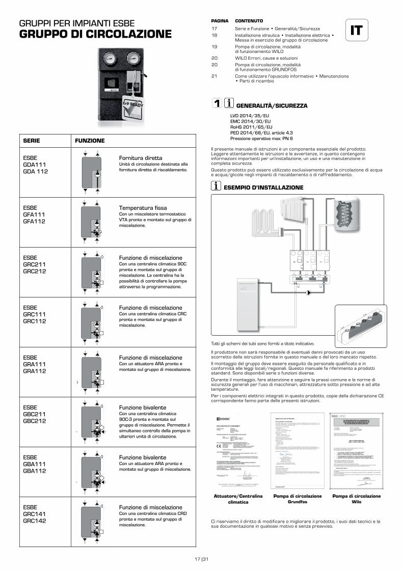
ITGRUPPI PER IMPIANTI ESBEGRUPPO DI CIRCOLAZIONE
Serie e Funzione • Generalità/Sicurezza
Installazione idraulica • Installazione elettrica • Messa in esercizio del gruppo di circolazione
Pompa di circolazione, modalità di funzionamento WILO
WILO Errori, cause e soluzioni
Pompa di circolazione, modalità di funzionamento GRUNDFOS
Come utilizzare l'opuscolo informativo • Manutenzione • Parti di ricambio
PAGINA CONTENUTO
17
18
19
20
20
21
GENERALITÀ/SICUREZZA
LVD 2014/35/EUEMC 2014/30/EURoHS 2011/65/EUPED 2014/68/EU, article 4.3 Pressione operativa max: PN 6
Il presente manuale di istruzioni è un componente essenziale del prodotto. Leggere attentamente le istruzioni e le avvertenze, in quanto contengono informazioni importanti per un'installazione, un uso e una manutenzione in completa sicurezza.
Questo prodotto può essere utilizzato esclusivamente per la circolazione di acqua e acqua/glicole negli impianti di riscaldamento o di raffreddamento.
ESEMPIO D’INSTALLAZIONE
Tutti gli schemi dei tubi sono forniti a titolo indicativo.
Il produttore non sarà responsabile di eventuali danni provocati da un uso scorretto delle istruzioni fornite in questo manuale o del loro mancato rispetto.
Il montaggio del gruppo deve essere eseguito da personale qualificato e in conformità alle leggi locali/regionali. Questo manuale fa riferimento a prodotti standard. Sono disponibili serie o funzioni diverse.
Durante il montaggio, fare attenzione e seguire la prassi comune e le norme di sicurezza generali per l'uso di macchinari, attrezzature sotto pressione e ad alte temperature.
Per i componenti elettrici integrati in questo prodotto, copie della dichiarazione CE corrispondente fanno parte delle presenti istruzioni.
Attuatore/Centralina climatica
Pompa di circolazioneGrundfos
54
UPM3
EC declaration of conformityWe, Grundfos, declare under our sole responsibility that the products GFNJB (UPM variants with user interface) and GFNJC (other UPM3 variants) , to which this declaration relates, are in conformity with these Council directives on the approximation of the laws of the EC member states:
Low Voltage Directive (2006/95/EC)Standards used:
EN 60335-1:2012/AC:2014EN 60335-2-51:2003/A1:2008/A2:2012
EMC Directive (2004/108/EC)Standards used:
EN 55014-1:2006/A1:2009EN 55014-2:1997/A1:2001/A2:2008
Ecodesign Directive (2009/125/EC)Commission Regulation (EC) No 641/2009Commission Regulation (EC) No 622/20012Standards used:
EN 16297-1:2012EN 16297-2:2012EN 16297-3:2012
WarningThe use of this product requires experience with and knowledge of the product. Persons with reduced physical, sensory or mental capabilities must not use this product, unless they are under supervision or have been instructed in the use of the product by a person responsible for their safety. Children must not use or play with this product.
Bjerringbro, 21st of February 2014
Preben Jakobsen Technical Manager - HVAC OEM
GRUNDFOS Holding A/SPoul Due Jensens Vej 7
8850 Bjerringbro, Denmark
Person authorised to compile technical file and empowered to sign the EC declaration of conformity.
VDE certificateThese pumps are certified by VDE.Product code: GFNJB or GFNJCVDE certificate No. 40039416This Marks Approval forms the basis of the CE declaration of conformity and the CE marking by the manufacturer or his agent and proves the conformity with the essential safety requirements of the EC Low Voltage Directive (2006/95/EC) including amendments.
Approvals and certificates
Pompa di circolazioneWilo
The supplier: Le Fabricant : Der Hersteller:
WILO INTEC 50 Avenue Eugène CASELLA 18700 AUBIGNY SUR NERE FRANCE
certifies that the following pumps, déclare que le type de circulateurs désigné ci-dessous, erklärt, dass die unten genannten Pumpentypen,
WILO YONOS PARA RK WILO YONOS PARA PWM
are meeting the requirements of the European legislation concerning: sont conformes aux dispositions des directives : mit folgenden Richtlinien übereinstimmen:
and the national legislations referring to them. et aux législations nationales les transposant. und entsprechender nationaler Gesetzgebung.
They are also meeting the following European Standards: Elles sont également conformes aux dispositions des normes européennes harmonisées suivantes : Des weiteren entsprechen sie den folgenden harmonisierten europäischen Normen:
NF EN 60.335.1&2.51
If the above mentioned series are technically modified without our approval, this declaration shall no longer be applicable. Si les séries mentionnées ci-dessus sont techniquement modifiées sans notre approbation, cette déclaration ne sera plus applicable. Bei einer mit uns nicht abgestimmten technischen Änderung der oben genannten Bauarten, verliert diese Erklärung ihre Gültigkeit.
M.PERROT
Quality Manager
Aubigny-sur-Nère, the 29th of November 2011
~ "Low Voltage" modified (European law Nr 2006/95/EC) ~ "Basse Tension"modifiée (Directives 2006/95/CE) ~ geänderte "Niederspannung" (Richtlinie 2006/95/EG)
~ "Electromagnetic Compatibility" modified (European law Nr 2004/108/EC) ~ "Compatibilité Electromagnétique" modifiée (Directives 2004/108/CE) ~ geänderte "elektromagnetische Verträglichkeit" (Richtlinie 2004/108/EG)
EC DECLARATION OF CONFORMITY DECLARATION DE CONFORMITE CE
EG KONFORMITÄTSERKLÄRUNG
Ci riserviamo il diritto di modificare o migliorare il prodotto, i suoi dati tecnici e la sua documentazione in qualsiasi motivo e senza preavviso.
SERIE FUNZIONE
ESBE GDA111GDA 112
Fornitura direttaUnità di circolazione destinata alla fornitura diretta di riscaldamento.
ESBE GFA111GFA112
Temperatura fissaCon un miscelatore termostatico VTA pronto e montato sul gruppo di miscelazione.
ESBE GRC211GRC212
Funzione di miscelazioneCon una centralina climatica 90C pronta e montata sul gruppo di miscelazione. La centralina ha la possibilità di controllare la pompa attraverso la programmazione.
ESBE GRC111GRC112
Funzione di miscelazioneCon una centralina climatica CRC pronta e montata sul gruppo di miscelazione.
ESBE GRA111GRA112
Funzione di miscelazioneCon un attuatore ARA pronto e montato sul gruppo di miscelazione.
ESBE GBC211GBC212
Funzione bivalenteCon una centralina climatica 90C-3 pronta e montata sul gruppo di miscelazione. Permette il simultaneo controllo della pompa in ulteriori unità di circolazione.
ESBE GBA111GBA112
Funzione bivalenteCon un attuatore ARA pronto e montato sul gruppo di miscelazione.
ESBE GRC141GRC142
Funzione di miscelazioneCon una centralina climatica CRD pronta e montata sul gruppo di miscelazione.
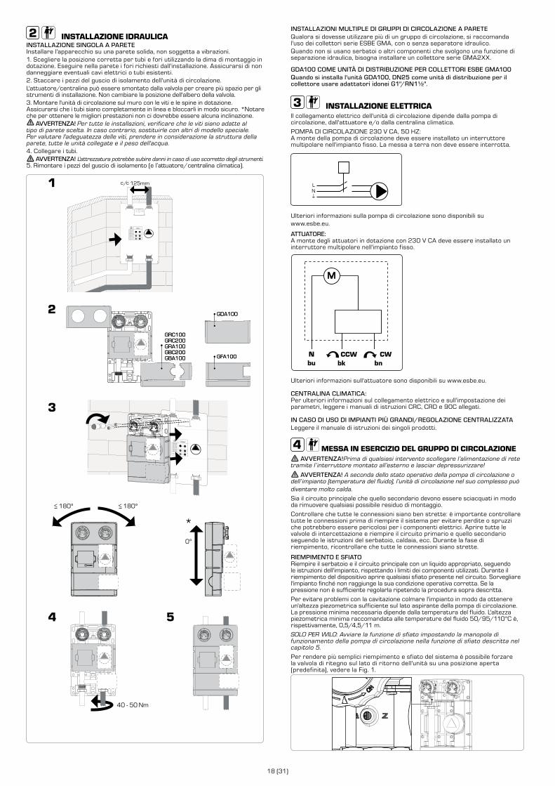
18 (31)
INSTALLAZIONE IDRAULICAINSTALLAZIONE SINGOLA A PARETE Installare l'apparecchio su una parete solida, non soggetta a vibrazioni.1. Scegliere la posizione corretta per tubi e fori utilizzando la dima di montaggio in dotazione. Eseguire nella parete i fori richiesti dall'installazione. Assicurarsi di non danneggiare eventuali cavi elettrici o tubi esistenti. 2. Staccare i pezzi del guscio di isolamento dell'unità di circolazione.L'attuatore/centralina può essere smontato dalla valvola per creare più spazio per gli strumenti di installazione. Non cambiare la posizione dell'albero della valvola.3. Montare l'unità di circolazione sul muro con le viti e le spine in dotazione. Assicurarsi che i tubi siano completamente in linea e bloccarli in modo sicuro. *Notare che per ottenere le migliori prestazioni non ci dovrebbe essere alcuna inclinazione.
AVVERTENZA! Per tutte le installazioni, verificare che le viti siano adatte al tipo di parete scelta. In caso contrario, sostituirle con altri di modello speciale. Per valutare l'adeguatezza delle viti, prendere in considerazione la struttura della parete, tutte le unità collegate e il peso dell'acqua. 4. Collegare i tubi.
AVVERTENZA! L'attrezzatura potrebbe subire danni in caso di uso scorretto degli strumenti.5. Rimontare i pezzi del guscio di isolamento (e l’attuatore/centralina climatica).
GDA100
GFA100
GRC100GRC200GRA100GBC200GBA100
180º>180º>
0º
GDA100
GFA100
40 - 50 Nm
GRC100GRC200GRA100GBC200GBA100
*
INSTALLAZIONI MULTIPLE DI GRUPPI DI CIRCOLAZIONE A PARETEQualora si dovesse utilizzare più di un gruppo di circolazione, si raccomanda l'uso dei collettori serie ESBE GMA, con o senza separatore idraulico.Quando non si usano serbatoi o altri componenti che svolgono una funzione di separazione idraulica, bisogna installare un collettore serie GMA2XX.
GDA100 COME UNITÀ DI DISTRIBUZIONE PER COLLETTORI ESBE GMA100Quando si installa l'unità GDA100, DN25 come unità di distribuzione per il collettore usare adattatori idonei G1"/RN1½".
INSTALLAZIONE ELETTRICAIl collegamento elettrico dell'unità di circolazione dipende dalla pompa di circolazione, dall'attuatore e/o dalla centralina climatica.
POMPA DI CIRCOLAZIONE 230 V CA, 50 HZ:A monte della pompa di circolazione deve essere installato un interruttore multipolare nell'impianto fisso. La messa a terra non deve essere interrotta.
LN
Ulteriori informazioni sulla pompa di circolazione sono disponibili su www.esbe.eu.
ATTUATORE:A monte degli attuatori in dotazione con 230 V CA deve essere installato un interruttore multipolare nell'impianto fisso.
M
Ulteriori informazioni sull'attuatore sono disponibili su www.esbe.eu.
CENTRALINA CLIMATICA:Per ulteriori informazioni sul collegamento elettrico e sull'impostazione dei parametri, leggere i manuali di istruzioni CRC, CRD e 90C allegati.
IN CASO DI USO DI IMPIANTI PIÙ GRANDI/REGOLAZIONE CENTRALIZZATA Leggere il manuale di istruzioni dei singoli prodotti.
MESSA IN ESERCIZIO DEL GRUPPO DI CIRCOLAZIONE AVVERTENZA!Prima di qualsiasi intervento scollegare l’alimentazione di rete
tramite l’ interruttore montato all’esterno e lasciar depressurizzare!
AVVERTENZA! A seconda dello stato operativo della pompa di circolazione o dell’ impianto (temperatura del fluido), l’unità di circolazione nel suo complesso può diventare molto calda.
Sia il circuito principale che quello secondario devono essere sciacquati in modo da rimuovere qualsiasi possibile residuo di montaggio.
Controllare che tutte le connessioni siano ben strette: è importante controllare tutte le connessioni prima di riempire il sistema per evitare perdite o spruzzi che potrebbero essere pericolosi per i componenti elettrici. Aprire tutte le valvole di intercettazione e riempire il circuito primario e quello secondario seguendo le istruzioni del serbatoio, caldaia, ecc. Durante la fase di riempimento, ricontrollare che tutte le connessioni siano strette.
RIEMPIMENTO E SFIATORiempire il serbatoio e il circuito principale con un liquido appropriato, seguendo le istruzioni dell'impianto, rispettando i limiti dei componenti utilizzati. Durante il riempimento del dispositivo aprire qualsiasi sfiato presente nel circuito. Sorvegliare l'impianto finché non raggiunge la sua condizione operativa corretta. Se la pressione non è sufficiente regolarla ripetendo la procedura sopra descritta.
Per evitare problemi con la cavitazione colmare l'impianto in modo da ottenere un'altezza piezometrica sufficiente sul lato aspirante della pompa di circolazione. La pressione minima necessaria dipende dalla temperatura del fluido. L'altezza piezometrica minima raccomandata alle temperature del fluido 50/95/110°C è, rispettivamente, 0,5/4,5/11 m.
SOLO PER WILO: Avviare la funzione di sfiato impostando la manopola di funzionamento della pompa di circolazione nella funzione di sfiato descritta nel capitolo 5.
Per rendere più semplici riempimento e sfiato del sistema è possibile forzare la valvola di ritegno sul lato di ritorno dell'unità su una posizione aperta (predefinita), vedere la Fig. 1.
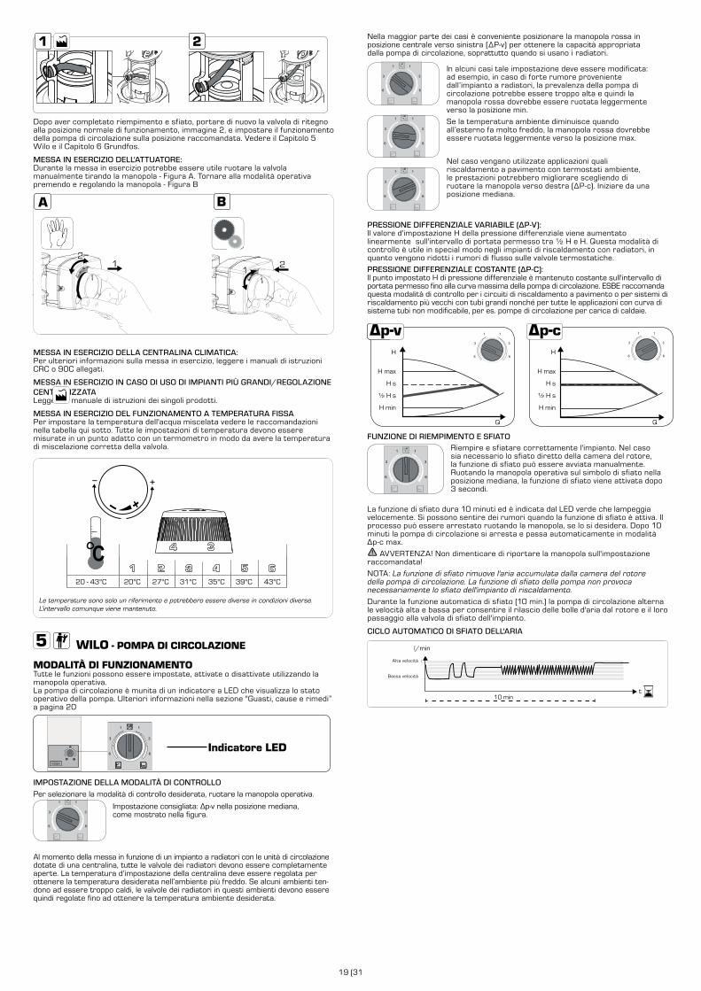
19 (31
Nella maggior parte dei casi è conveniente posizionare la manopola rossa in posizione centrale verso sinistra (ΔP-v) per ottenere la capacità appropriata dalla pompa di circolazione, soprattutto quando si usano i radiatori.
In alcuni casi tale impostazione deve essere modificata: ad esempio, in caso di forte rumore proveniente dall’impianto a radiatori, la prevalenza della pompa di circolazione potrebbe essere troppo alta e quindi la manopola rossa dovrebbe essere ruotata leggermente verso la posizione min.
Se la temperatura ambiente diminuisce quando all’esterno fa molto freddo, la manopola rossa dovrebbe essere ruotata leggermente verso la posizione max.
Nel caso vengano utilizzate applicazioni quali riscaldamento a pavimento con termostati ambiente, le prestazioni potrebbero migliorare scegliendo di ruotare la manopola verso destra (ΔP-c). Iniziare da una posizione mediana.
PRESSIONE DIFFERENZIALE VARIABILE (ΔP-V):Il valore d'impostazione H della pressione differenziale viene aumentato linearmente sull'intervallo di portata permesso tra ½ H e H. Questa modalità di controllo è utile in special modo negli impianti di riscaldamento con radiatori, in quanto vengono ridotti i rumori di flusso sulle valvole termostatiche.
PRESSIONE DIFFERENZIALE COSTANTE (ΔP-C):Il punto impostato H di pressione differenziale è mantenuto costante sull'intervallo di portata permesso fino alla curva massima della pompa di circolazione. ESBE raccomanda questa modalità di controllo per i circuiti di riscaldamento a pavimento o per sistemi di riscaldamento più vecchi con tubi grandi nonché per tutte le applicazioni con curva di sistema tubi non modificabile, per es. pompe di circolazione per carica di caldaie.
H
H max
H s
½ H s
H min
Q
H
H max
H s
½ H s
H min
Q
FUNZIONE DI RIEMPIMENTO E SFIATORiempire e sfiatare correttamente l'impianto. Nel caso sia necessario lo sfiato diretto della camera del rotore, la funzione di sfiato può essere avviata manualmente. Ruotando la manopola operativa sul simbolo di sfiato nella posizione mediana, la funzione di sfiato viene attivata dopo 3 secondi.
La funzione di sfiato dura 10 minuti ed è indicata dal LED verde che lampeggia velocemente. Si possono sentire dei rumori quando la funzione di sfiato è attiva. Il processo può essere arrestato ruotando la manopola, se lo si desidera. Dopo 10 minuti la pompa di circolazione si arresta e passa automaticamente in modalità Δp-c max.
AVVERTENZA! Non dimenticare di riportare la manopola sull'impostazione raccomandata!
NOTA: La funzione di sfiato rimuove l'aria accumulata dalla camera del rotore della pompa di circolazione. La funzione di sfiato della pompa non provoca necessariamente lo sfiato dell'impianto di riscaldamento.
Durante la funzione automatica di sfiato (10 min.) la pompa di circolazione alterna le velocità alta e bassa per consentire il rilascio delle bolle d'aria dal rotore e il loro passaggio alla valvola di sfiato dell'impianto.
CICLO AUTOMATICO DI SFIATO DELL'ARIA
high speed
low speed
l/min
high speed
t
low speed
10 min
Alta velocità
Bassa velocità
Dopo aver completato riempimento e sfiato, portare di nuovo la valvola di ritegno alla posizione normale di funzionamento, immagine 2, e impostare il funzionamento della pompa di circolazione sulla posizione raccomandata. Vedere il Capitolo 5 Wilo e il Capitolo 6 Grundfos.
MESSA IN ESERCIZIO DELL'ATTUATORE:Durante la messa in esercizio potrebbe essere utile ruotare la valvola manualmente tirando la manopola - Figura A. Tornare alla modalità operativa premendo e regolando la manopola - Figura B
1
MESSA IN ESERCIZIO DELLA CENTRALINA CLIMATICA: Per ulteriori informazioni sulla messa in esercizio, leggere i manuali di istruzioni CRC o 90C allegati.
MESSA IN ESERCIZIO IN CASO DI USO DI IMPIANTI PIÙ GRANDI/REGOLAZIONE CENTRALIZZATA Leggere il manuale di istruzioni dei singoli prodotti.
MESSA IN ESERCIZIO DEL FUNZIONAMENTO A TEMPERATURA FISSAPer impostare la temperatura dell'acqua miscelata vedere le raccomandazioni nella tabella qui sotto. Tutte le impostazioni di temperatura devono essere misurate in un punto adatto con un termometro in modo da avere la temperatura di miscelazione corretta della valvola.
20 - 43°C 20°C 27°C 31°C 35°C 39°C 43°C
Le temperature sono solo un riferimento e potrebbero essere diverse in condizioni diverse. L’intervallo comunque viene mantenuto.
WILO - POMPA DI CIRCOLAZIONE
MODALITÀ DI FUNZIONAMENTOTutte le funzioni possono essere impostate, attivate o disattivate utilizzando la manopola operativa. La pompa di circolazione è munita di un indicatore a LED che visualizza lo stato operativo della pompa. Ulteriori informazioni nella sezione "Guasti, cause e rimedi” a pagina 20
Indicatore LED
IMPOSTAZIONE DELLA MODALITÀ DI CONTROLLOPer selezionare la modalità di controllo desiderata, ruotare la manopola operativa.
Impostazione consigliata: Δp-v nella posizione mediana, come mostrato nella figura.
Al momento della messa in funzione di un impianto a radiatori con le unità di circolazione dotate di una centralina, tutte le valvole dei radiatori devono essere completamente aperte. La temperatura d’impostazione della centralina deve essere regolata per ottenere la temperatura desiderata nell’ambiente più freddo. Se alcuni ambienti ten-dono ad essere troppo caldi, le valvole dei radiatori in questi ambienti devono essere quindi regolate fino ad ottenere la temperatura ambiente desiderata.
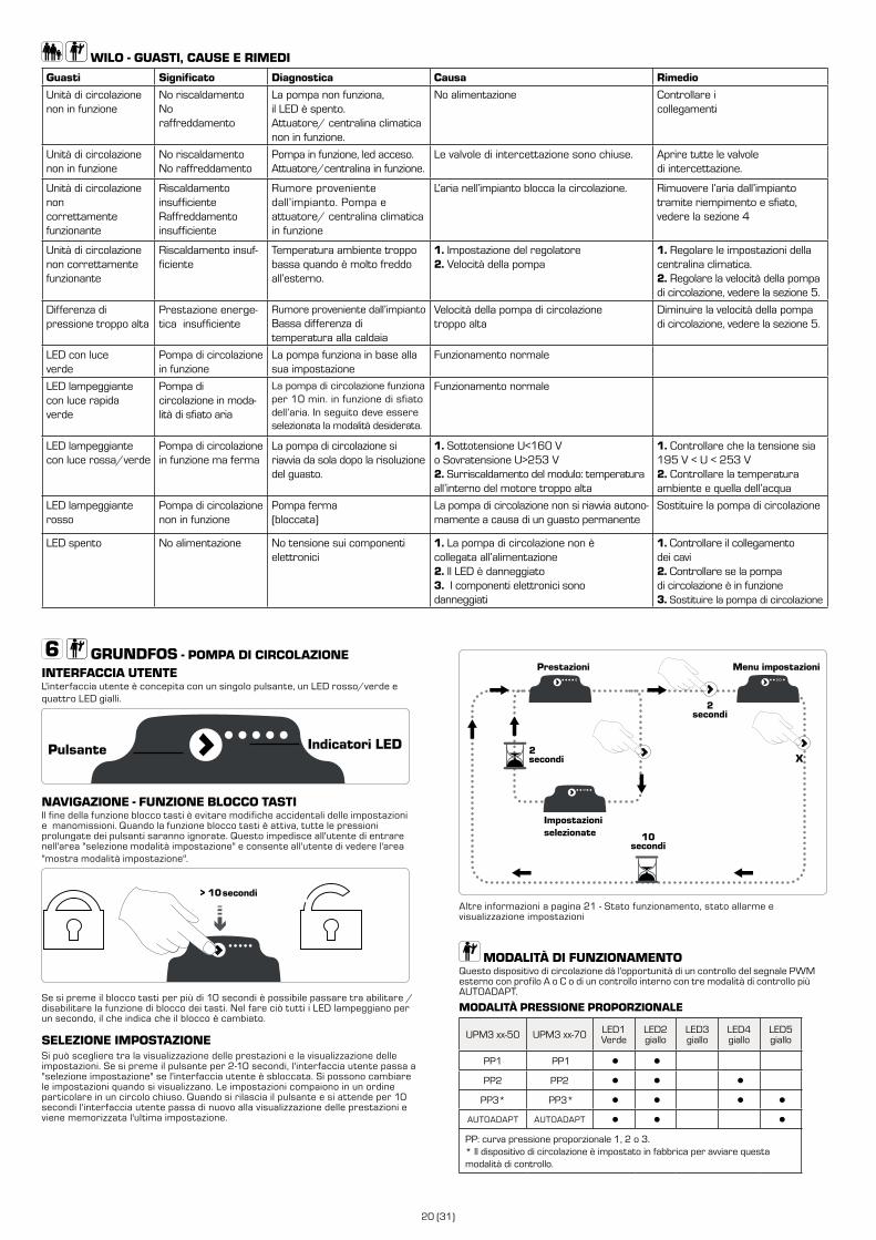
20 (31)
GRUNDFOS - POMPA DI CIRCOLAZIONE INTERFACCIA UTENTEL'interfaccia utente è concepita con un singolo pulsante, un LED rosso/verde e quattro LED gialli.
NAVIGAZIONE - FUNZIONE BLOCCO TASTIIl fine della funzione blocco tasti è evitare modifiche accidentali delle impostazioni e manomissioni. Quando la funzione blocco tasti è attiva, tutte le pressioni prolungate dei pulsanti saranno ignorate. Questo impedisce all'utente di entrare nell'area "selezione modalità impostazione" e consente all'utente di vedere l'area "mostra modalità impostazione".
> 10 seksecondi
Se si preme il blocco tasti per più di 10 secondi è possibile passare tra abilitare / disabilitare la funzione di blocco dei tasti. Nel fare ciò tutti i LED lampeggiano per un secondo, il che indica che il blocco è cambiato.
SELEZIONE IMPOSTAZIONESi può scegliere tra la visualizzazione delle prestazioni e la visualizzazione delle impostazioni. Se si preme il pulsante per 2-10 secondi, l'interfaccia utente passa a "selezione impostazione" se l'interfaccia utente è sbloccata. Si possono cambiare le impostazioni quando si visualizzano. Le impostazioni compaiono in un ordine particolare in un circolo chiuso. Quando si rilascia il pulsante e si attende per 10 secondi l'interfaccia utente passa di nuovo alla visualizzazione delle prestazioni e viene memorizzata l'ultima impostazione.
WILO - GUASTI, CAUSE E RIMEDI
Guasti Significato Diagnostica Causa Rimedio
Unità di circolazione non in funzione
No riscaldamentoNo raffreddamento
La pompa non funziona,il LED è spento.Attuatore/ centralina climatica non in funzione.
No alimentazione Controllare i collegamenti
Unità di circolazione non in funzione
No riscaldamentoNo raffreddamento
Pompa in funzione, led acceso.Attuatore/centralina in funzione.
Le valvole di intercettazione sono chiuse. Aprire tutte le valvole di intercettazione.
Unità di circolazione non correttamente funzionante
Riscaldamento insufficienteRaffreddamento insufficiente
Rumore proveniente dall’impianto. Pompa e attuatore/ centralina climatica in funzione
L’aria nell’impianto blocca la circolazione. Rimuovere l’aria dall’impianto tramite riempimento e sfiato, vedere la sezione 4
Unità di circolazione non correttamente funzionante
Riscaldamento insuf-ficiente
Temperatura ambiente troppo bassa quando è molto freddo all’esterno.
1. Impostazione del regolatore2. Velocità della pompa
1. Regolare le impostazioni della centralina climatica.2. Regolare la velocità della pompa di circolazione, vedere la sezione 5.
Differenza di pressione troppo alta
Prestazione energe-tica insufficiente
Rumore proveniente dall’impiantoBassa differenza di temperatura alla caldaia
Velocità della pompa di circolazione troppo alta
Diminuire la velocità della pompa di circolazione, vedere la sezione 5.
LED con luceverde
Pompa di circolazione in funzione
La pompa funziona in base alla sua impostazione
Funzionamento normale
LED lampeggiantecon luce rapidaverde
Pompa di circolazione in moda-lità di sfiato aria
La pompa di circolazione funziona per 10 min. in funzione di sfiato dell’aria. In seguito deve essere selezionata la modalità desiderata.
Funzionamento normale
LED lampeggiantecon luce rossa/verde
Pompa di circolazione in funzione ma ferma
La pompa di circolazione si riavvia da sola dopo la risoluzione del guasto.
1. Sottotensione U<160 Vo Sovratensione U>253 V2. Surriscaldamento del modulo: temperatura all’interno del motore troppo alta
1. Controllare che la tensione sia 195 V < U < 253 V2. Controllare la temperatura ambiente e quella dell’acqua
LED lampeggiante rosso
Pompa di circolazione non in funzione
Pompa ferma (bloccata)
La pompa di circolazione non si riavvia autono-mamente a causa di un guasto permanente
Sostituire la pompa di circolazione
LED spento No alimentazione No tensione sui componenti elettronici
1. La pompa di circolazione non è collegata all’alimentazione2. Il LED è danneggiato3. I componenti elettronici sono danneggiati
1. Controllare il collegamento dei cavi2. Controllare se la pompa di circolazione è in funzione3. Sostituire la pompa di circolazione
X
Impostazioni selezionate
2secondi
2secondi
10secondi
Prestazioni Menu impostazioni
Altre informazioni a pagina 21 - Stato funzionamento, stato allarme e visualizzazione impostazioni
MODALITÀ DI FUNZIONAMENTOQuesto dispositivo di circolazione dà l'opportunità di un controllo del segnale PWM esterno con profilo A o C o di un controllo interno con tre modalità di controllo più AUTOADAPT.
MODALITÀ PRESSIONE PROPORZIONALE
UPM3 xx-50 UPM3 xx-70 LED1Verde
LED2giallo
LED3giallo
LED4giallo
LED5giallo
PP1 PP1 ● ●
PP2 PP2 ● ● ●
PP3* PP3* ● ● ● ●
AUTOADAPT AUTOADAPT ● ● ●
PP: curva pressione proporzionale 1, 2 o 3.* Il dispositivo di circolazione è impostato in fabbrica per avviare questa modalità di controllo.
Indicatori LEDPulsante
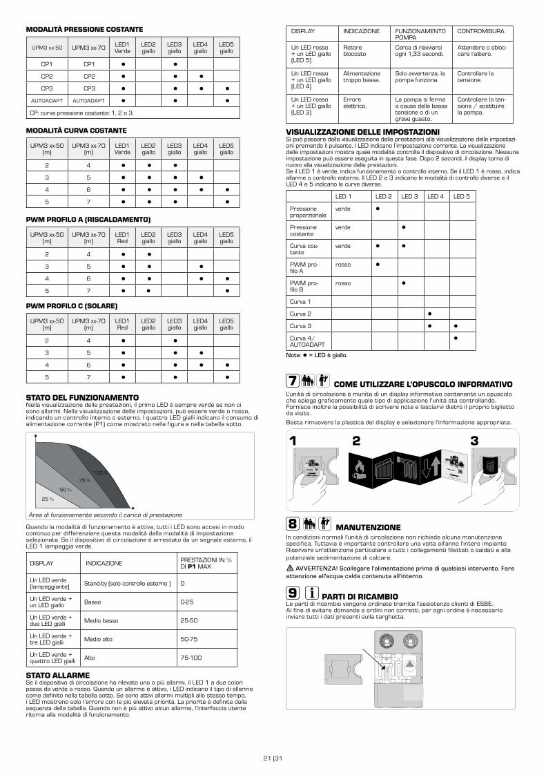
21 (31
MODALITÀ PRESSIONE COSTANTE
UPM3 xx-50 UPM3 xx-70 LED1Verde
LED2giallo
LED3giallo
LED4giallo
LED5giallo
CP1 CP1 ● ●
CP2 CP2 ● ● ●
CP3 CP3 ● ● ● ●
AUTOADAPT AUTOADAPT ● ● ●
CP: curva pressione costante: 1, 2 o 3.
MODALITÀ CURVA COSTANTE
UPM3 xx-50(m)
UPM3 xx-70(m)
LED1Verde
LED2giallo
LED3giallo
LED4giallo
LED5giallo
2 4 ● ● ●
3 5 ● ● ● ●
4 6 ● ● ● ● ●
5 7 ● ● ● ●
PWM PROFILO A (RISCALDAMENTO)
UPM3 xx-50(m)
UPM3 xx-70(m)
LED1Red
LED2giallo
LED3giallo
LED4giallo
LED5giallo
2 4 ● ●
3 5 ● ● ●
4 6 ● ● ● ●
5 7 ● ● ●
PWM PROFILO C (SOLARE)
UPM3 xx-50(m)
UPM3 xx-70(m)
LED1Red
LED2giallo
LED3giallo
LED4giallo
LED5giallo
2 4 ● ●
3 5 ● ● ●
4 6 ● ● ● ●
5 7 ● ● ●
STATO DEL FUNZIONAMENTONella visualizzazione delle prestazioni, il primo LED è sempre verde se non ci sono allarmi. Nella visualizzazione delle impostazioni, può essere verde o rosso, indicando un controllo interno o esterno. I quattro LED gialli indicano il consumo di alimentazione corrente (P1) come mostrato nella figura e nella tabella sotto.
100 %
75 %
50 %
25 %
Area di funzionamento secondo il carico di prestazione
Quando la modalità di funzionamento è attiva, tutti i LED sono accesi in modo continuo per differenziare questa modalità dalla modalità di impostazione selezionata. Se il dispositivo di circolazione è arrestato da un segnale esterno, il LED 1 lampeggia verde.
DISPLAY INDICAZIONE PRESTAZIONI IN % DI P1 MAX
Un LED verde (lampeggiante) Stand-by (solo controllo esterno ) 0
Un LED verde + un LED giallo Basso 0-25
Un LED verde + due LED gialli Medio basso 25-50
Un LED verde + tre LED gialli Medio alto 50-75
Un LED verde + quattro LED gialli Alto 75-100
STATO ALLARMESe il dispositivo di circolazione ha rilevato uno o più allarmi, il LED 1 a due colori passa da verde a rosso. Quando un allarme è attivo, i LED indicano il tipo di allarme come definito nella tabella sotto. Se sono attivi allarmi multipli allo stesso tempo, i LED mostrano solo l’errore con la più elevata priorità. La priorità è definita dalla sequenza della tabella. Quando non è più attivo alcun allarme, l’interfaccia utente ritorna alla modalità di funzionamento.
DISPLAY INDICAZIONE FUNZIONAMENTO POMPA
CONTROMISURA
Un LED rosso + un LED giallo (LED 5)
Rotore bloccato
Cerca di riavviarsi ogni 1,33 secondi.
Attendere o sbloc-care l’albero.
Un LED rosso + un LED giallo (LED 4)
Alimentazione troppo bassa.
Solo avvertenza, la pompa funziona.
Controllare la tensione.
Un LED rosso + un LED giallo (LED 3)
Errore elettrico.
La pompa si ferma a causa della bassa tensione o di un grave guasto.
Controllare la ten-sione / sostituire la pompa.
VISUALIZZAZIONE DELLE IMPOSTAZIONISi può passare dalla visualizzazione delle prestazioni alla visualizzazione delle impostazi-oni premendo il pulsante. I LED indicano l’impostazione corrente. La visualizzazione delle impostazioni mostra quale modalità controlla il dispositivo di circolazione. Nessuna impostazione può essere eseguita in questa fase. Dopo 2 secondi, il display torna di nuovo alla visualizzazione delle prestazioni.Se il LED 1 è verde, indica funzionamento o controllo interno. Se il LED 1 è rosso, indica allarme o controllo esterno. Il LED 2 e 3 indicano le modalità di controllo diverse e il LED 4 e 5 indicano le curve diverse.
LED 1 LED 2 LED 3 LED 4 LED 5
Pressione proporzionale
verde ●
Pressione costante
verde ●
Curva cos-tante
verde ● ●
PWM pro-filo A
rosso ●
PWM pro-filo B
rosso ●
Curva 1
Curva 2 ●
Curva 3 ● ●
Curva 4/AUTOADAPT
●
Note: ● = LED è giallo.
COME UTILIZZARE L’OPUSCOLO INFORMATIVOL'unità di circolazione è munita di un display informativo contenente un opuscolo che spiega graficamente quale tipo di applicazione l'unità sta controllando. Fornisce inoltre la possibilità di scrivere note e lasciarvi dietro il proprio biglietto da visita.
Basta rimuovere la plastica del display e selezionare l'informazione appropriata.
MANUTENZIONEIn condizioni normali l'unità di circolazione non richiede alcuna manutenzione specifica. Tuttavia è importante controllare una volta all'anno l'intero impianto. Riservare un'attenzione particolare a tutti i collegamenti filettati o saldati e alla potenziale sedimentazione di calcare.
AVVERTENZA! Scollegare l'alimentazione prima di qualsiasi intervento. Fare attenzione all'acqua calda contenuta all'interno.
PARTI DI RICAMBIOLe parti di ricambio vengono ordinate tramite l'assistenza clienti di ESBE. Al fine di evitare domande e ordini non corretti, per ogni ordine è necessario inviare tutti i dati presenti sulla targhetta.
GXX X00
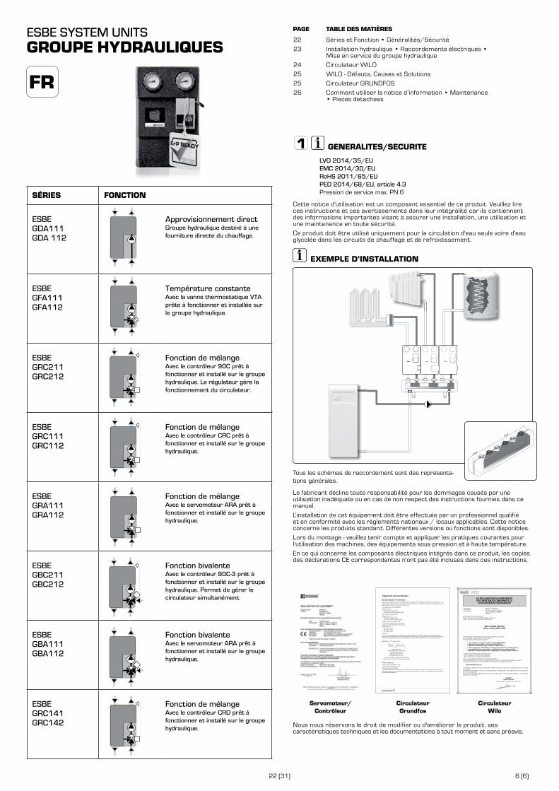
22 (31) 6 (6)
ESBE SYSTEM UNITSGROUPE HYDRAULIQUES
Séries et Fonction • Généralités/Sécurité
Installation hydraulique • Raccordements électriques • Mise en service du groupe hydraulique
Circulateur WILO
WILO - Défauts, Causes et Solutions
Circulateur GRUNDFOS
Comment utiliser la notice d’information • Maintenance • Pieces detachees
PAGE TABLE DES MATIÈRES
22
23
24
25
25
26
GENERALITES/SECURITE
LVD 2014/35/EUEMC 2014/30/EURoHS 2011/65/EUPED 2014/68/EU, article 4.3 Pression de service max. PN 6
Cette notice d'utilisation est un composant essentiel de ce produit. Veuillez lire ces instructions et ces avertissements dans leur intégralité car ils contiennent des informations importantes visant à assurer une installation, une utilisation et une maintenance en toute sécurité.
Ce produit doit être utilisé uniquement pour la circulation d'eau seule voire d'eau glycolée dans les circuits de chauffage et de refroidissement.
EXEMPLE D’INSTALLATION
Tous les schémas de raccordement sont des représenta-tions générales.
Le fabricant décline toute responsabilité pour les dommages causés par une utilisation inadéquate ou en cas de non respect des instructions fournies dans ce manuel.
L'installation de cet équipement doit être effectuée par un professionnel qualifié et en conformité avec les règlements nationaux / locaux applicables. Cette notice concerne les produits standard. Différentes versions ou fonctions sont disponibles.
Lors du montage - veuillez tenir compte et appliquer les pratiques courantes pour l'utilisation des machines, des équipements sous pression et à haute température.
En ce qui concerne les composants électriques intégrés dans ce produit, les copies des déclarations CE correspondantes n'ont pas été incluses dans ces instructions.
Servomoteur/Contrôleur
Circulateur Grundfos
54
UPM3
EC declaration of conformityWe, Grundfos, declare under our sole responsibility that the products GFNJB (UPM variants with user interface) and GFNJC (other UPM3 variants) , to which this declaration relates, are in conformity with these Council directives on the approximation of the laws of the EC member states:
Low Voltage Directive (2006/95/EC)Standards used:
EN 60335-1:2012/AC:2014EN 60335-2-51:2003/A1:2008/A2:2012
EMC Directive (2004/108/EC)Standards used:
EN 55014-1:2006/A1:2009EN 55014-2:1997/A1:2001/A2:2008
Ecodesign Directive (2009/125/EC)Commission Regulation (EC) No 641/2009Commission Regulation (EC) No 622/20012Standards used:
EN 16297-1:2012EN 16297-2:2012EN 16297-3:2012
WarningThe use of this product requires experience with and knowledge of the product. Persons with reduced physical, sensory or mental capabilities must not use this product, unless they are under supervision or have been instructed in the use of the product by a person responsible for their safety. Children must not use or play with this product.
Bjerringbro, 21st of February 2014
Preben Jakobsen Technical Manager - HVAC OEM
GRUNDFOS Holding A/SPoul Due Jensens Vej 7
8850 Bjerringbro, Denmark
Person authorised to compile technical file and empowered to sign the EC declaration of conformity.
VDE certificateThese pumps are certified by VDE.Product code: GFNJB or GFNJCVDE certificate No. 40039416This Marks Approval forms the basis of the CE declaration of conformity and the CE marking by the manufacturer or his agent and proves the conformity with the essential safety requirements of the EC Low Voltage Directive (2006/95/EC) including amendments.
Approvals and certificates
Circulateur Wilo
The supplier: Le Fabricant : Der Hersteller:
WILO INTEC 50 Avenue Eugène CASELLA 18700 AUBIGNY SUR NERE FRANCE
certifies that the following pumps, déclare que le type de circulateurs désigné ci-dessous, erklärt, dass die unten genannten Pumpentypen,
WILO YONOS PARA RK WILO YONOS PARA PWM
are meeting the requirements of the European legislation concerning: sont conformes aux dispositions des directives : mit folgenden Richtlinien übereinstimmen:
and the national legislations referring to them. et aux législations nationales les transposant. und entsprechender nationaler Gesetzgebung.
They are also meeting the following European Standards: Elles sont également conformes aux dispositions des normes européennes harmonisées suivantes : Des weiteren entsprechen sie den folgenden harmonisierten europäischen Normen:
NF EN 60.335.1&2.51
If the above mentioned series are technically modified without our approval, this declaration shall no longer be applicable. Si les séries mentionnées ci-dessus sont techniquement modifiées sans notre approbation, cette déclaration ne sera plus applicable. Bei einer mit uns nicht abgestimmten technischen Änderung der oben genannten Bauarten, verliert diese Erklärung ihre Gültigkeit.
M.PERROT
Quality Manager
Aubigny-sur-Nère, the 29th of November 2011
~ "Low Voltage" modified (European law Nr 2006/95/EC) ~ "Basse Tension"modifiée (Directives 2006/95/CE) ~ geänderte "Niederspannung" (Richtlinie 2006/95/EG)
~ "Electromagnetic Compatibility" modified (European law Nr 2004/108/EC) ~ "Compatibilité Electromagnétique" modifiée (Directives 2004/108/CE) ~ geänderte "elektromagnetische Verträglichkeit" (Richtlinie 2004/108/EG)
EC DECLARATION OF CONFORMITY DECLARATION DE CONFORMITE CE
EG KONFORMITÄTSERKLÄRUNG
Nous nous réservons le droit de modifier ou d'améliorer le produit, ses caractéristiques techniques et les documentations à tout moment et sans préavis.
FR
SÉRIES FONCTION
ESBE GDA111GDA 112
Approvisionnement directGroupe hydraulique destiné à une fourniture directe du chauffage.
ESBE GFA111GFA112
Température constanteAvec la vanne thermostatique VTA prête à fonctionner et installée sur le groupe hydraulique.
ESBE GRC211GRC212
Fonction de mélangeAvec le contrôleur 90C prêt à fonctionner et installé sur le groupe hydraulique. Le régulateur gère le fonctionnement du circulateur.
ESBE GRC111GRC112
Fonction de mélangeAvec le contrôleur CRC prêt à fonctionner et installé sur le groupe hydraulique.
ESBE GRA111GRA112
Fonction de mélangeAvec le servomoteur ARA prêt à fonctionner et installé sur le groupe hydraulique.
ESBE GBC211GBC212
Fonction bivalenteAvec le contrôleur 90C-3 prêt à fonctionner et installé sur le groupe hydraulique. Permet de gérer le circulateur simultanément.
ESBE GBA111GBA112
Fonction bivalenteAvec le servomoteur ARA prêt à fonctionner et installé sur le groupe hydraulique.
ESBE GRC141GRC142
Fonction de mélangeAvec le contrôleur CRD prêt à fonctionner et installé sur le groupe hydraulique.
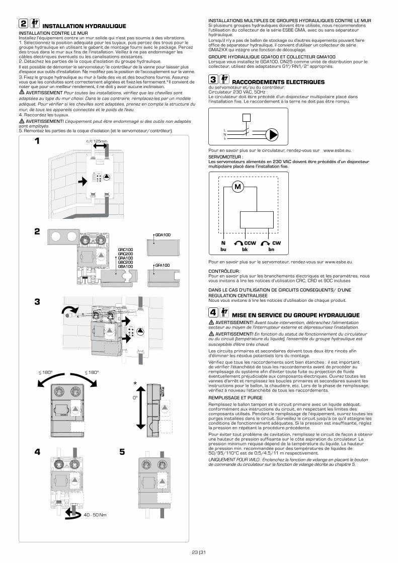
23 (31
INSTALLATION HYDRAULIQUEINSTALLATION CONTRE LE MUR Installez l'équipement contre un mur solide qui n'est pas soumis à des vibrations.1. Sélectionnez la position adéquate pour les tuyaux, puis percez des trous pour le groupe hydraulique en utilisant le gabarit de montage fourni avec le package. Percez des trous dans le mur aux fins de l'installation. Veillez à ne pas endommager les câbles électriques éventuels ou les canalisations existantes. 2. Détachez les parties de la coque d'isolation du groupe hydraulique.Il est possible de démonter le servomoteur/le contrôleur de la vanne pour laisser plus d'espace aux outils d'installation. Ne modifiez pas la position de l'accouplement sur la vanne.3. Fixez le groupe hydraulique au mur à l'aide des vis et des bouchons fournis. Assurez-vous que les conduites sont correctement alignées et fixez-les fermement.*Il convient de noter que pour un meilleur rendement, il ne doit y avoir aucune inclinaison.
AVERTISSEMENT Pour toutes les installations, vérifiez que les chevilles sont adaptées au type du mur choisi. Dans le cas contraire, remplacez-les par un modèle adéquat. Pour vérifier si les chevilles sont adaptées, prenez en compte la structure du mur, de tous les appareils connectés et le poids de l'eau. 4. Raccordez les tuyaux.
AVERTISSEMENT! L'équipement peut être endommagé si des outils non adaptés sont employés.5. Remontez les parties de la coque d’isolation (et le servomoteur/contrôleur).
GDA100
GFA100
GRC100GRC200GRA100GBC200GBA100
180º>180º>
0º
GDA100
GFA100
40 - 50 Nm
GRC100GRC200GRA100GBC200GBA100
*
INSTALLATIONS MULTIPLES DE GROUPES HYDRAULIQUES CONTRE LE MURSi plusieurs groupes hydrauliques doivent être utilisés, nous recommandons l'utilisation du collecteur de la série ESBE GMA, avec ou sans séparateur hydraulique.Lorsqu'il n'y a pas de ballon de stockage ou d'autres équipements pouvant faire office de séparateur hydraulique, il convient d'utiliser un collecteur de série GMA2XX qui intègre une fonction de découplage.
GROUPE HYDRAULIQUE GDA100 ET COLLECTEUR GMA100Lorsque vous installez le GDA100, DN25 comme unité de distribution pour le collecteur, utilisez des adaptateurs G1"/RN1/2'' appropriés.
RACCORDEMENTS ELECTRIQUESdu servomoteur et/ou du contrôleur. Circulateur 230 VAC, 50Hz :Le circulateur doit être précédé d'un disjoncteur multipolaire placé dans l'installation fixe. Le raccordement à la terre ne doit pas être rompu.
LN
Pour en savoir plus sur le circulateur, rendez-vous sur www.esbe.eu.
SERVOMOTEUR :Les servomoteurs alimentés en 230 VAC doivent être précédés d’un disjoncteur multipolaire placé dans l’installation fixe.
M
Pour en savoir plus sur le servomoteur, rendez-vous sur www.esbe.eu.
CONTRÔLEUR:Pour en savoir plus sur les branchements électriques et les paramètres, nous vous invitons à lire les notices d'utilisation CRC, CRD et 90C incluses
DANS LE CAS D'UTILISATION DE CIRCUITS CONSEQUENTS/ D'UNE REGULATION CENTRALISEE Nous vous invitons à lire les notices d'utilisation de chaque produit.
MISE EN SERVICE DU GROUPE HYDRAULIQUE AVERTISSEMENT! Avant toute intervention, débranchez l'alimentation
secteur au moyen de l'interrupteur externe et dépressurisez l'installation.
AVERTISSEMENT! En fonction du statut de fonctionnement du circulateur ou du circuit (température du liquide), l'ensemble du groupe hydraulique est susceptible d'être très chaud.
Les circuits primaires et secondaires doivent tous deux être rincés afin d'éliminer les résidus potentiels lors du montage.
Vérifiez que tous les raccordements sont bien étanches : il est important de vérifier l'étanchéité de tous les raccordements avant de procéder au remplissage du système afin d'éviter toute fuite ou projection de fluide éventuellement préjudiciable aux composants électriques. Ouvrez toutes les vannes d'arrêt et remplissez les boucles primaires et secondaires suivant les instructions pour le ballon, la chaudière, etc. Lors de la phase de remplissage, vérifiez à nouveau l'étanchéité de tous les raccordements.
REMPLISSAGE ET PURGERemplissez le ballon tampon et le circuit primaire avec un liquide adéquat, conformément aux instructions du circuit, en respectant les limites des composants utilisés. Pendant le remplissage de l'équipement, ouvrez toutes les purges installées dans le circuit. Surveillez le circuit jusqu'à ce qu'il atteigne les conditions de fonctionnement adéquates. Si la pression est insuffisante, réglez la pression en répétant la procédure précédente.
Pour éviter tout problème de cavitation, remplissez le circuit de façon à obtenir une hauteur de pression suffisante sur le côté aspiration du circulateur. La pression minimum requise dépend de la température du liquide. La hauteur de pression min. recommandée pour des températures de liquides de 50/95/110°C est de 0,5/4,5/11 m respectivement.
UNIQUEMENT POUR WILO : Enclenchez la fonction de vidange en plaçant le bouton de commande du circulateur sur la fonction de vidange décrite au chapitre 5.
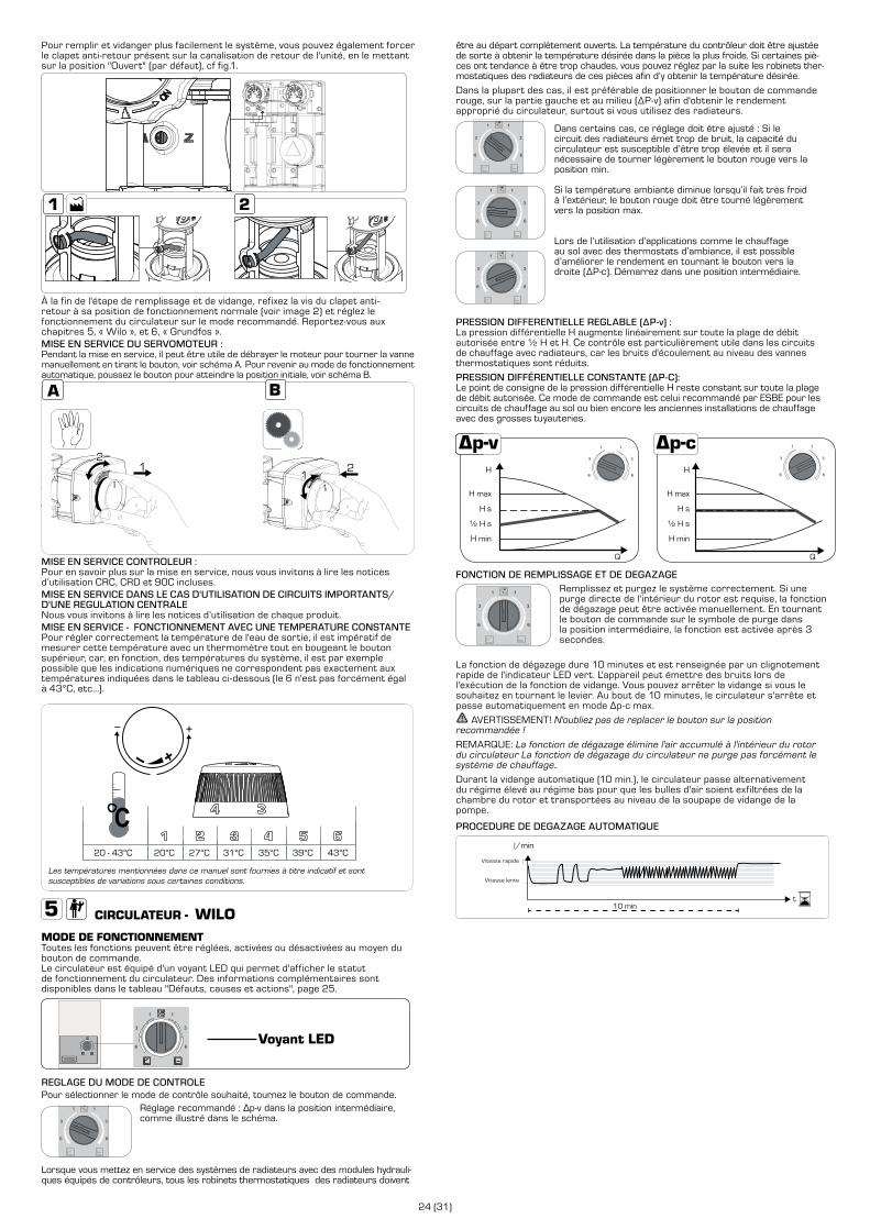
24 (31)
être au départ complètement ouverts. La température du contrôleur doit être ajustée de sorte à obtenir la température désirée dans la pièce la plus froide. Si certaines piè-ces ont tendance à être trop chaudes, vous pouvez réglez par la suite les robinets ther-mostatiques des radiateurs de ces pièces afin d’y obtenir la température désirée.
Dans la plupart des cas, il est préférable de positionner le bouton de commande rouge, sur la partie gauche et au milieu (ΔP-v) afin d'obtenir le rendement approprié du circulateur, surtout si vous utilisez des radiateurs.
Dans certains cas, ce réglage doit être ajusté : Si le circuit des radiateurs émet trop de bruit, la capacité du circulateur est susceptible d’être trop élevée et il sera nécessaire de tourner légèrement le bouton rouge vers la position min.
Si la température ambiante diminue lorsqu’il fait très froid à l’extérieur, le bouton rouge doit être tourné légèrement vers la position max.
Lors de l’utilisation d’applications comme le chauffage au sol avec des thermostats d’ambiance, il est possible d’améliorer le rendement en tournant le bouton vers la droite (ΔP-c). Démarrez dans une position intermédiaire.
PRESSION DIFFERENTIELLE REGLABLE (ΔP-v) :La pression différentielle H augmente linéairement sur toute la plage de débit autorisée entre ½ H et H. Ce contrôle est particulièrement utile dans les circuits de chauffage avec radiateurs, car les bruits d'écoulement au niveau des vannes thermostatiques sont réduits.
PRESSION DIFFÉRENTIELLE CONSTANTE (ΔP-C):Le point de consigne de la pression différentielle H reste constant sur toute la plage de débit autorisée. Ce mode de commande est celui recommandé par ESBE pour les circuits de chauffage au sol ou bien encore les anciennes installations de chauffage avec des grosses tuyauteries.
H
H max
H s
½ H s
H min
Q
H
H max
H s
½ H s
H min
Q
FONCTION DE REMPLISSAGE ET DE DEGAZAGERemplissez et purgez le système correctement. Si une purge directe de l'intérieur du rotor est requise, la fonction de dégazage peut être activée manuellement. En tournant le bouton de commande sur le symbole de purge dans la position intermédiaire, la fonction est activée après 3 secondes.
La fonction de dégazage dure 10 minutes et est renseignée par un clignotement rapide de l'indicateur LED vert. L'appareil peut émettre des bruits lors de l'exécution de la fonction de vidange. Vous pouvez arrêter la vidange si vous le souhaitez en tournant le levier. Au bout de 10 minutes, le circulateur s'arrête et passe automatiquement en mode Δp-c max.
AVERTISSEMENT! N'oubliez pas de replacer le bouton sur la position recommandée !
REMARQUE: La fonction de dégazage élimine l'air accumulé à l'intérieur du rotor du circulateur La fonction de dégazage du circulateur ne purge pas forcément le système de chauffage..
Durant la vidange automatique (10 min.), le circulateur passe alternativement du régime élevé au régime bas pour que les bulles d'air soient exfiltrées de la chambre du rotor et transportées au niveau de la soupape de vidange de la pompe.
PROCEDURE DE DEGAZAGE AUTOMATIQUE
high speed
low speed
l/min
high speed
t
low speed
10 min
Vitesse rapide
Vitesse lente
Pour remplir et vidanger plus facilement le système, vous pouvez également forcer le clapet anti-retour présent sur la canalisation de retour de l'unité, en le mettant sur la position "Ouvert" (par défaut), cf fig.1.
À la fin de l'étape de remplissage et de vidange, refixez la vis du clapet anti-retour à sa position de fonctionnement normale (voir image 2) et réglez le fonctionnement du circulateur sur le mode recommandé. Reportez-vous aux chapitres 5, « Wilo », et 6, « Grundfos ».MISE EN SERVICE DU SERVOMOTEUR :Pendant la mise en service, il peut être utile de débrayer le moteur pour tourner la vanne manuellement en tirant le bouton, voir schéma A. Pour revenir au mode de fonctionnement automatique, poussez le bouton pour atteindre la position initiale, voir schéma B.
1
MISE EN SERVICE CONTROLEUR :Pour en savoir plus sur la mise en service, nous vous invitons à lire les notices d’utilisation CRC, CRD et 90C incluses.MISE EN SERVICE DANS LE CAS D'UTILISATION DE CIRCUITS IMPORTANTS/ D'UNE REGULATION CENTRALENous vous invitons à lire les notices d’utilisation de chaque produit.MISE EN SERVICE - FONCTIONNEMENT AVEC UNE TEMPERATURE CONSTANTEPour régler correctement la température de l'eau de sortie, il est impératif de mesurer cette température avec un thermomètre tout en bougeant le bouton supérieur, car, en fonction, des températures du système, il est par exemple possible que les indications numériques ne correspondent pas exactement aux températures indiquées dans le tableau ci-dessous (le 6 n'est pas forcément égal à 43°C, etc...).
20 - 43°C 20°C 27°C 31°C 35°C 39°C 43°C
Les températures mentionnées dans ce manuel sont fournies à titre indicatif et sont susceptibles de variations sous certaines conditions.
CIRCULATEUR - WILOMODE DE FONCTIONNEMENTToutes les fonctions peuvent être réglées, activées ou désactivées au moyen du bouton de commande. Le circulateur est équipé d'un voyant LED qui permet d'afficher le statut de fonctionnement du circulateur. Des informations complémentaires sont disponibles dans le tableau "Défauts, causes et actions", page 25.
Voyant LED
REGLAGE DU MODE DE CONTROLEPour sélectionner le mode de contrôle souhaité, tournez le bouton de commande.
Réglage recommandé : Δp-v dans la position intermédiaire, comme illustré dans le schéma.
Lorsque vous mettez en service des systèmes de radiateurs avec des modules hydrauli-ques équipés de contrôleurs, tous les robinets thermostatiques des radiateurs doivent
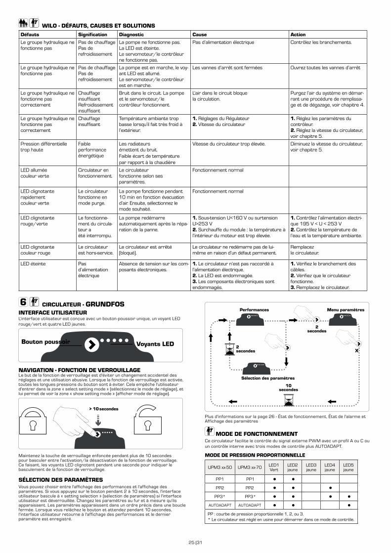
25 (31
CIRCULATEUR - GRUNDFOS INTERFACE UTILISATEURL'interface utilisateur est conçue avec un bouton-poussoir unique, un voyant LED rouge/vert et quatre LED jaunes.
NAVIGATION - FONCTION DE VERROUILLAGELe but de la fonction de verrouillage est d'éviter un changement accidentel des réglages et une utilisation abusive. Lorsque la fonction de verrouillage est activée, toutes les longues pressions du bouton sont à éviter. Cela empêche l'utilisateur d'entrer dans la zone « select setting mode » (sélectionnez le mode de réglage), et lui permet de voir la zone « show setting mode » (afficher mode de réglage).
> 10 seksecondes
Maintenez la touche de verrouillage enfoncée pendant plus de 10 secondes pour basculer entre l'activation/la désactivation de la fonction de verrouillage. Ce faisant, les voyants LED clignotent pendant une seconde pour indiquer le basculement de la fonction de verrouillage.
SÉLECTION DES PARAMÈTRESVous pouvez choisir entre l'affichage des performances et l'affichage des paramètres. Si vous appuyez sur le bouton pendant 2 à 10 secondes, l'interface utilisateur bascule à « setting selection » (sélection de paramètres) si l'interface utilisateur est déverrouillée. Changez les paramètres au fur et à mesure qu'ils apparaissent. Les paramètres apparaissent dans un ordre précis dans une boucle fermée. Lorsque vous relâchez le bouton et attendez pendant 10 secondes, l'interface utilisateur retourne à l'affichage des performances et le dernier paramètre est enregistré.
WILO - DÉFAUTS, CAUSES ET SOLUTIONS
Défauts Signification Diagnostic Cause Action
Le groupe hydraulique ne fonctionne pas
Pas de chauffagePas de refroidissement
La pompe ne fonctionne pas.La LED est éteinte.Le servomoteur/le contrôleur ne fonctionne pas.
Pas d’alimentation électrique Contrôlez les branchements.
Le groupe hydraulique ne fonctionne pas
Pas de chauffagePas de refroidissement
La pompe est en marche, le voy-ant LED est allumé.Le servomoteur/le contrôleur est en marche.
Les vannes d’arrêt sont fermées Ouvrez toutes les vannes d’arrêt
Le groupe hydraulique ne fonctionne pas correctement
Chauffage insuffisantRefroidissement insuffisant
Bruit dans le circuit. La pompe et le servomoteur/le contrôleur fonctionnent.
L’air dans le circuit bloque la circulation.
Purgez l’air du système en démar-rant une procédure de remplissa-ge et de dégazage, voir chapitre 4.
Le groupe hydraulique ne fonctionne pas correctement
Chauffage insuffisant
Température ambiante trop basse lorsqu’il fait très froid à l’extérieur.
1. Réglages du Régulateur2. Vitesse du circulateur
1. Réglez les paramètres du contrôleur.2. Réglez la vitesse du circulateur, voir chapitre 5.
Pression différentielle trop haute
Faible performance énergétique
Les radiateurs émettent du bruit.Faible écart de température par rapport à la chaudière
Vitesse du circulateur trop élevée. Diminuez la vitesse du circulateur, voir chapitre 5.
LED alluméecouleur verte
Circulateur en fonctionnement.
Le circulateur fonctionne selon ses paramètres.
Fonctionnement normal
LED clignotanterapidementcouleur verte
Le circulateur fonctionne en mode purge.
La pompe fonctionne pendant 10 min en fonction évacuation d’air. Ensuite, sélectionnez le mode souhaité.
Fonctionnement normal
LED clignotanterouge/verte
Le fonctionne-ment du circula-teur a été interrompu.
La pompe redémarre automatiquement après la répa-ration de la panne.
1. Sous-tension U<160 V ou surtension U>253 V2. Surchauffe du module : la température à l’intérieur du moteur est trop élevée.
1. Contrôlez l’alimentation électri-que 195 V < U < 253 V2. Contrôlez la température de l’eau et la température ambiante.
LED clignotantecouleur rouge
Le circulateur est hors-service.
Le circulateur est arrêté (bloqué).
Le circulateur ne redémarre pas de lui-même en raison d’un défaut permanent.
Remplacez le circulateur.
LED éteinte Pas d’alimentation électrique
Absence de tension sur les com-posants électroniques.
1. Le circulateur n’est pas raccordé à l’alimentation électrique.2. La LED est endommagée.3. Les composants électroniques sont endommagés.
1. Vérifiez le branchement des câbles.2. Vérifiez que le circulateur fonctionne.3. Remplacez le circulateur.
X
Sélection des paramètres
2secondes
2secondes
10secondes
Performances Menu paramètres
Plus d'informations sur la page 26 - État de fonctionnement, État de l'alarme et Affichage des paramètres
MODE DE FONCTIONNEMENTCe circulateur facilite le contrôle du signal externe PWM avec un profil A ou C ou un contrôle interne avec trois modes de contrôle plus AUTOADAPT.
MODE DE PRESSION PROPORTIONNELLE
UPM3 xx-50 UPM3 xx-70 LED1Vert
LED2jaune
LED3jaune
LED4jaune
LED5jaune
PP1 PP1 ● ●
PP2 PP2 ● ● ●
PP3* PP3* ● ● ● ●
AUTOADAPT AUTOADAPT ● ● ●
PP : courbe de pression proportionnelle 1, 2, ou 3.* Le circulateur est réglé en usine pour démarrer dans ce mode de contrôle.
Voyants LEDBouton poussoir
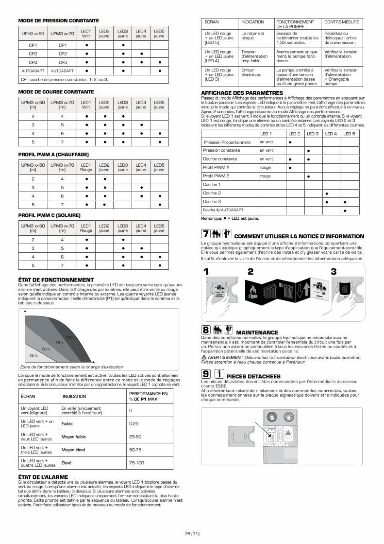
26 (31)
MODE DE PRESSION CONSTANTE
UPM3 xx-50 UPM3 xx-70 LED1Vert
LED2jaune
LED3jaune
LED4jaune
LED5jaune
CP1 CP1 ● ●
CP2 CP2 ● ● ●
CP3 CP3 ● ● ● ●
AUTOADAPT AUTOADAPT ● ● ●
CP : courbe de pression constante : 1, 2, ou 3.
MODE DE COURBE CONSTANTE
UPM3 xx-50(m)
UPM3 xx-70(m)
LED1Vert
LED2jaune
LED3jaune
LED4jaune
LED5jaune
2 4 ● ● ●
3 5 ● ● ● ●
4 6 ● ● ● ● ●
5 7 ● ● ● ●
PROFIL PWM A (CHAUFFAGE)
UPM3 xx-50(m)
UPM3 xx-70(m)
LED1Rouge
LED2jaune
LED3jaune
LED4jaune
LED5jaune
2 4 ● ●
3 5 ● ● ●
4 6 ● ● ● ●
5 7 ● ● ●
PROFIL PWM C (SOLAIRE)
UPM3 xx-50(m)
UPM3 xx-70(m)
LED1Rouge
LED2jaune
LED3jaune
LED4jaune
LED5jaune
2 4 ● ●
3 5 ● ● ●
4 6 ● ● ● ●
5 7 ● ● ●
ÉTAT DE FONCTIONNEMENTDans l'affichage des performances, la première LED est toujours verte tant qu'aucune alarme n'est activée. Dans l'affichage des paramètres, elle peut être verte ou rouge selon qu'elle indique un contrôle interne ou externe. Les quatre voyants LED jaunes indiquent la consommation réelle d'électricité (P1) tel qu'indiqué dans le schéma et le tableau ci-dessous.
100 %
75 %
50 %
25 %
Zone de fonctionnement selon la charge d'exécution
Lorsque le mode de fonctionnement est activé, toutes les LED actives sont allumées en permanence afin de faire la différence entre ce mode et le mode de réglages sélectionné. Si le circulateur s'arrête par un signal externe, le voyant LED 1 clignote en vert.
ÉCRAN INDICATIONPERFORMANCE EN % DE P1 MAX
Un voyant LED vert (clignote)
En veille (uniquement contrôlé à l’extérieur) 0
Un LED vert + un LED jaune Faible 0-25
Un LED vert + deux LED jaunes Moyen faible 25-50
Un LED vert + trois LED jaunes Moyen élevé 50-75
Un LED vert + quatre LED jaunes Élevé 75-100
ÉTAT DE L’ALARMESi le circulateur a détecté une ou plusieurs alarmes, le voyant LED 1 bicolore passe du vert au rouge. Lorsqu’une alarme est activée, les voyants LED indiquent le type d’alarme tel que défini dans le tableau ci-dessous. Si plusieurs alarmes sont activéessimultanément, les voyants LED indiquent uniquement l’erreur nécessitant la plus haute priorité. Cette priorité est définie par la séquence du tableau. Lorsqu’aucune alarme n’est activée, l’interface utilisateur bascule de nouveau au mode de fonctionnement.
ÉCRAN INDICATION FONCTIONNEMENT DE LA POMPE
CONTRE-MESURE
Un LED rouge + un LED jaune (LED 5)
Le rotor est bloqué
Essayez de redémarrer toutes les 1,33 secondes.
Patientez ou débloquez l’arbre de transmission.
Un LED rouge + un LED jaune (LED 4)
Tension d’alimentation trop faible.
Avertissement unique-ment, la pompe fonc-tionne.
Vérifiez la tension d’alimentation.
Un LED rouge + un LED jaune (LED 3)
Erreur électrique.
La pompe s’arrête à cause d’une tension d’alimentation basse ou d’une grave panne.
Vérifiez la tension d’alimentation / Changez la pompe.
AFFICHAGE DES PARAMÈTRESPassez du mode Affichage des performances à Affichage des paramètres en appuyant sur le bouton-poussoir. Les voyants LED indiquent le paramètre réel. L’affichage des paramètres indique le mode qui contrôle le circulateur. Aucun réglage ne peut être effectué à ce niveau. Après 2 secondes, l’affichage retourne au mode Affichage des performances.Si le voyant LED 1 est vert, il indique le fonctionnement ou un contrôle interne. Si le voyant LED 1 est rouge, il indique une alarme ou un contrôle externe. Les voyants LED 2 et 3 indiquent les différents modes de contrôle et les LED 4 et 5 indiquent les différentes courbes.
LED 1 LED 2 LED 3 LED 4 LED 5
Pression Proportionnelle en vert ●
Pression constante en vert ●
Courbe constante en vert ● ●
Profil PWM A rouge ●
Profil PWM B rouge ●
Courbe 1
Courbe 2 ●
Courbe 3 ● ●
Courbe 4/AUTOADAPT ●
Remarque: ● = LED est jaune.
COMMENT UTILISER LA NOTICE D’INFORMATIONLe groupe hydraulique est équipé d'une affiche d'informations comportant une notice qui explique graphiquement le type d'application que l'équipement contrôle. Elle vous permet également d'écrire des notes et d'y glisser votre carte de visite.
Il suffit d'enlever la vitre de l'écran et de sélectionner les informations adéquates.
MAINTENANCEDans des conditions normales, le groupe hydraulique ne nécessite aucune maintenance. Il est important de contrôler l'ensemble du circuit une fois par an. Portez une attention particulière à tous les raccords filetés ou soudés et à l'apparition potentielle de sédimentation calcaire.
AVERTISSEMENT Débranchez l'alimentation électrique avant toute opération. Faites attention à l'eau chaude contenue à l'intérieur.
PIECES DETACHEESLes pièces détachées doivent être commandées par l'intermédiaire du service clients ESBE. Afin d'éviter tout retard de traitement et des commandes incorrectes, toutes les données mentionnées sur la plaque signalétique doivent être indiquées pour chaque commande.
GXX X00

27 (31
ESBE ROZWIĄZANIA SYSTEMOWEGRUPA POMPOWA
Seria i funkcja • Ogólne/Bezpieczeństwo
Instalacja hydrauliczna • Instalacja elektryczna
Uruchomienie • Tryb działania pompy cyrkulacyjnej WILO
WILO Usterki, przyczyny i rozwiązania
Tryb działania pompy cyrkulacyjnej GRUNDFOS
Sposób korzystania z ulotki informacyjnej • Konserwacja • Części zamienne
STRONA TREŚĆ
27
28
29
30
30
31
OGÓLNE/BEZPIECZEŃSTWO
LVD 2014/35/EUEMC 2014/30/EURoHS 2011/65/EUPED 2014/68/EU, article 4.3 Maks. ciśnienie podczas pracy: PN 6
Niniejsza instrukcja obsługi stanowi nieodłączny element produktu. Należy uważnie zapoznać się z instrukcjami i ostrzeżeniami, ponieważ przedstawiono w nich ważne informacje dotyczące bezpiecznego montażu, użytkowania i konserwacji.
Ten produkt może być używany wyłącznie w instalacjach grzewczych lub chłodniczych, w których czynnikiem jest woda lub mieszanka wodno-glikolowa.
PRZYKŁADOWA INSTALACJA
Wszystkie schematy połączeń rurowych są przykładami ogólnymi
Producent nie ponosi odpowiedzialności za szkody spowodowane nieprawidłowym użytkowaniem lub niestosowaniem się do wskazówek podanych w niniejszej instrukcji.
Montaż grupy pompowej powinna przeprowadzić wykwalifikowana osoba w sposób zgodny z przepisami lokalnymi/regionalnymi. Niniejsza instrukcja dotyczy produktów standardowych. Dostępne są inne wersje oraz funkcje.
Montaż należy przeprowadzić z rozwagą, zgodnie z powszechnie stosowaną praktyką oraz z normami bezpieczeństwa dotyczącymi użytkowania urządzeń oraz sprzętu, na który działa ciśnienie i wysokie temperatury.
Do niniejszej instrukcji dołączono odpowiednie deklaracje CE dotyczące komponentów elektrycznych stanowiących część tego produktu.
Siłownik/sterownik Pompa cyrkulacyjnaGrundfos
54
UPM3
EC declaration of conformityWe, Grundfos, declare under our sole responsibility that the products GFNJB (UPM variants with user interface) and GFNJC (other UPM3 variants) , to which this declaration relates, are in conformity with these Council directives on the approximation of the laws of the EC member states:
Low Voltage Directive (2006/95/EC)Standards used:
EN 60335-1:2012/AC:2014EN 60335-2-51:2003/A1:2008/A2:2012
EMC Directive (2004/108/EC)Standards used:
EN 55014-1:2006/A1:2009EN 55014-2:1997/A1:2001/A2:2008
Ecodesign Directive (2009/125/EC)Commission Regulation (EC) No 641/2009Commission Regulation (EC) No 622/20012Standards used:
EN 16297-1:2012EN 16297-2:2012EN 16297-3:2012
WarningThe use of this product requires experience with and knowledge of the product. Persons with reduced physical, sensory or mental capabilities must not use this product, unless they are under supervision or have been instructed in the use of the product by a person responsible for their safety. Children must not use or play with this product.
Bjerringbro, 21st of February 2014
Preben Jakobsen Technical Manager - HVAC OEM
GRUNDFOS Holding A/SPoul Due Jensens Vej 7
8850 Bjerringbro, Denmark
Person authorised to compile technical file and empowered to sign the EC declaration of conformity.
VDE certificateThese pumps are certified by VDE.Product code: GFNJB or GFNJCVDE certificate No. 40039416This Marks Approval forms the basis of the CE declaration of conformity and the CE marking by the manufacturer or his agent and proves the conformity with the essential safety requirements of the EC Low Voltage Directive (2006/95/EC) including amendments.
Approvals and certificates
Pompa cyrkulacyjnaWilo
The supplier: Le Fabricant : Der Hersteller:
WILO INTEC 50 Avenue Eugène CASELLA 18700 AUBIGNY SUR NERE FRANCE
certifies that the following pumps, déclare que le type de circulateurs désigné ci-dessous, erklärt, dass die unten genannten Pumpentypen,
WILO YONOS PARA RK WILO YONOS PARA PWM
are meeting the requirements of the European legislation concerning: sont conformes aux dispositions des directives : mit folgenden Richtlinien übereinstimmen:
and the national legislations referring to them. et aux législations nationales les transposant. und entsprechender nationaler Gesetzgebung.
They are also meeting the following European Standards: Elles sont également conformes aux dispositions des normes européennes harmonisées suivantes : Des weiteren entsprechen sie den folgenden harmonisierten europäischen Normen:
NF EN 60.335.1&2.51
If the above mentioned series are technically modified without our approval, this declaration shall no longer be applicable. Si les séries mentionnées ci-dessus sont techniquement modifiées sans notre approbation, cette déclaration ne sera plus applicable. Bei einer mit uns nicht abgestimmten technischen Änderung der oben genannten Bauarten, verliert diese Erklärung ihre Gültigkeit.
M.PERROT
Quality Manager
Aubigny-sur-Nère, the 29th of November 2011
~ "Low Voltage" modified (European law Nr 2006/95/EC) ~ "Basse Tension"modifiée (Directives 2006/95/CE) ~ geänderte "Niederspannung" (Richtlinie 2006/95/EG)
~ "Electromagnetic Compatibility" modified (European law Nr 2004/108/EC) ~ "Compatibilité Electromagnétique" modifiée (Directives 2004/108/CE) ~ geänderte "elektromagnetische Verträglichkeit" (Richtlinie 2004/108/EG)
EC DECLARATION OF CONFORMITY DECLARATION DE CONFORMITE CE
EG KONFORMITÄTSERKLÄRUNG
Zastrzegamy sobie prawo do modyfikowania oraz poprawiania produktu, jego danych technicznych oraz materiałów informacyjnych w dowolnym momencie i bez powiadomienia.
PL
SERIA FUNKCJA
ESBE GDA111GDA 112
Z zasilaniem bezpośrednimGrupa pompowa z bezpośrednim zasilaniem.
ESBE GFA111GFA112
Ze stałą temperaturąGrupa pompowa z termostatycznym zaworem mieszającym VTA.
ESBE GRC211GRC212
Z funkcją mieszaniaGrupa pompowa z zaworem mieszającym i z sterownikiem pogodowym 90C (możliwość sterowania pompą za pomoca programu czasowego).
ESBE GRC111GRC112
Z funkcją mieszaniaGrupa pompowa z zaworem mieszającym i z sterownikiem pogodowym CRC.
ESBE GRA111GRA112
Z funkcją mieszaniaGrupa pompowa z zaworem mieszającym i z siłownikiem ARA.
ESBE GBC211GBC212
Z systemem biwalentnymGrupa pompowa z zaworem biwalentnym mieszającym i z sterownikiem pogodowym 90C-3 (możliwość sterowania kilkoma pompami).
ESBE GBA111GBA112
Z systemem biwalentnymGrupa pompowa z zaworem biwalentnym mieszającym i z siłownikiem ARA.
ESBE GRC141GRC142
Z funkcją mieszaniaGrupa pompowa z zaworem mieszającym i z sterownikiem pogodowym CRD.
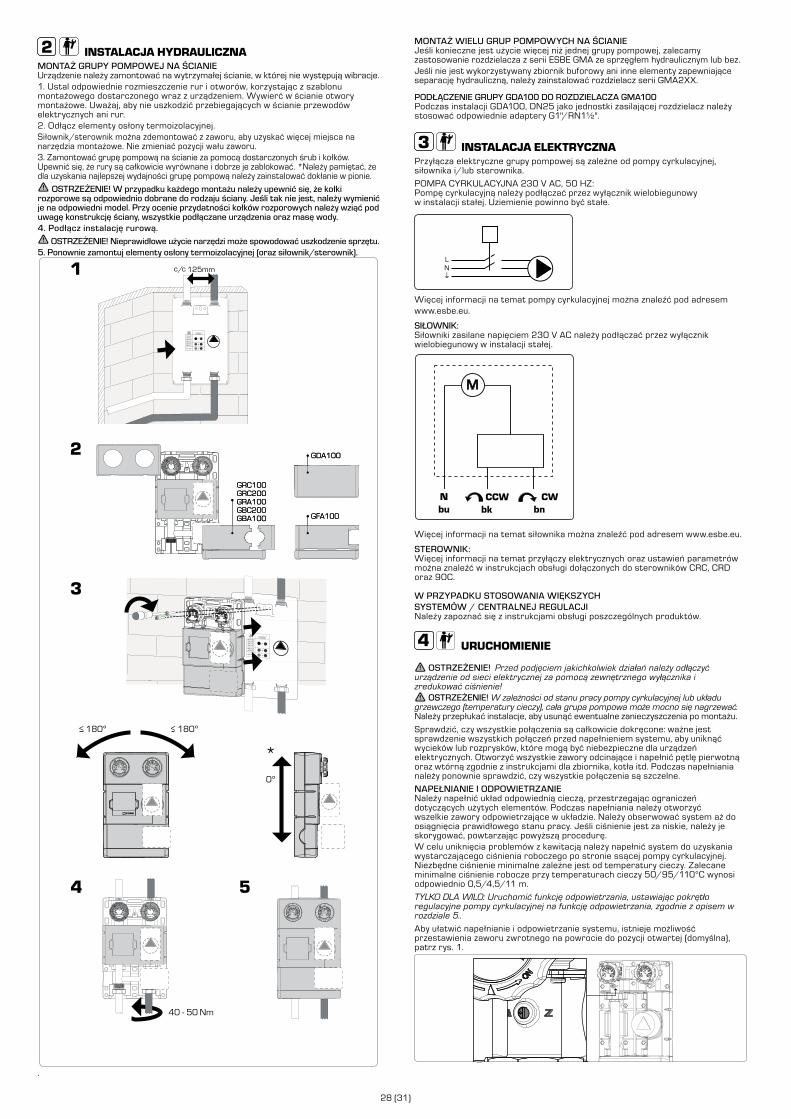
28 (31)
INSTALACJA HYDRAULICZNAMONTAŻ GRUPY POMPOWEJ NA ŚCIANIE Urządzenie należy zamontować na wytrzymałej ścianie, w której nie występują wibracje.1. Ustal odpowiednie rozmieszczenie rur i otworów, korzystając z szablonu montażowego dostarczonego wraz z urządzeniem. Wywierć w ścianie otwory montażowe. Uważaj, aby nie uszkodzić przebiegających w ścianie przewodów elektrycznych ani rur. 2. Odłącz elementy osłony termoizolacyjnej.Siłownik/sterownik można zdemontować z zaworu, aby uzyskać więcej miejsca na narzędzia montażowe. Nie zmieniać pozycji wału zaworu.3. Zamontować grupę pompową na ścianie za pomocą dostarczonych śrub i kołków. Upewnić się, że rury są całkowicie wyrównane i dobrze je zablokować. *Należy pamiętać, że dla uzyskania najlepszej wydajności grupę pompową należy zainstalować dokłanie w pionie.
OSTRZEŻENIE! W przypadku każdego montażu należy upewnić się, że kołki rozporowe są odpowiednio dobrane do rodzaju ściany. Jeśli tak nie jest, należy wymienić je na odpowiedni model. Przy ocenie przydatności kołków rozporowych należy wziąć pod uwagę konstrukcję ściany, wszystkie podłączane urządzenia oraz masę wody. 4. Podłącz instalację rurową.
OSTRZEŻENIE! Nieprawidłowe użycie narzędzi może spowodować uszkodzenie sprzętu.5. Ponownie zamontuj elementy osłony termoizolacyjnej (oraz siłownik/sterownik).
.
GDA100
GFA100
GRC100GRC200GRA100GBC200GBA100
180º>180º>
0º
GDA100
GFA100
40 - 50 Nm
GRC100GRC200GRA100GBC200GBA100
*
MONTAŻ WIELU GRUP POMPOWYCH NA ŚCIANIEJeśli konieczne jest użycie więcej niż jednej grupy pompowej, zalecamy zastosowanie rozdzielacza z serii ESBE GMA ze sprzęgłem hydraulicznym lub bez. Jeśli nie jest wykorzystywany zbiornik buforowy ani inne elementy zapewniające separację hydrauliczną, należy zainstalować rozdzielacz serii GMA2XX.
PODŁĄCZENIE GRUPY GDA100 DO ROZDZIELACZA GMA100Podczas instalacji GDA100, DN25 jako jednostki zasilającej rozdzielacz należy stosować odpowiednie adaptery G1"/RN1½".
INSTALACJA ELEKTRYCZNAPrzyłącza elektryczne grupy pompowej są zależne od pompy cyrkulacyjnej, siłownika i/lub sterownika.
POMPA CYRKULACYJNA 230 V AC, 50 HZ:Pompę cyrkulacyjną należy podłączać przez wyłącznik wielobiegunowy w instalacji stałej. Uziemienie powinno być stałe.
LN
Więcej informacji na temat pompy cyrkulacyjnej można znaleźć pod adresem www.esbe.eu.
SIŁOWNIK:Siłowniki zasilane napięciem 230 V AC należy podłączać przez wyłącznik wielobiegunowy w instalacji stałej.
M
Więcej informacji na temat siłownika można znaleźć pod adresem www.esbe.eu.
STEROWNIK:Więcej informacji na temat przyłączy elektrycznych oraz ustawień parametrów można znaleźć w instrukcjach obsługi dołączonych do sterowników CRC, CRD oraz 90C.
W PRZYPADKU STOSOWANIA WIĘKSZYCH SYSTEMÓW / CENTRALNEJ REGULACJI Należy zapoznać się z instrukcjami obsługi poszczególnych produktów.
URUCHOMIENIE
OSTRZEŻENIE! Przed podjęciem jakichkolwiek działań należy odłączyć urządzenie od sieci elektrycznej za pomocą zewnętrznego wyłącznika i zredukować ciśnienie!
OSTRZEŻENIE! W zależności od stanu pracy pompy cyrkulacyjnej lub układu grzewczego (temperatury cieczy), cała grupa pompowa może mocno się nagrzewać. Należy przepłukać instalacje, aby usunąć ewentualne zanieczyszczenia po montażu.
Sprawdzić, czy wszystkie połączenia są całkowicie dokręcone: ważne jest sprawdzenie wszystkich połączeń przed napełnieniem systemu, aby uniknąć wycieków lub rozprysków, które mogą być niebezpieczne dla urządzeń elektrycznych. Otworzyć wszystkie zawory odcinające i napełnić pętlę pierwotną oraz wtórną zgodnie z instrukcjami dla zbiornika, kotła itd. Podczas napełniania należy ponownie sprawdzić, czy wszystkie połączenia są szczelne.
NAPEŁNIANIE I ODPOWIETRZANIENależy napełnić układ odpowiednią cieczą, przestrzegając ograniczeń dotyczących użytych elementów. Podczas napełniania należy otworzyć wszelkie zawory odpowietrzające w układzie. Należy obserwować system aż do osiągnięcia prawidłowego stanu pracy. Jeśli ciśnienie jest za niskie, należy je skorygować, powtarzając powyższą procedurę.W celu uniknięcia problemów z kawitacją należy napełnić system do uzyskania wystarczającego ciśnienia roboczego po stronie ssącej pompy cyrkulacyjnej. Niezbędne ciśnienie minimalne zależne jest od temperatury cieczy. Zalecane minimalne ciśnienie robocze przy temperaturach cieczy 50/95/110°C wynosi odpowiednio 0,5/4,5/11 m.
TYLKO DLA WILO: Uruchomić funkcję odpowietrzania, ustawiając pokrętło regulacyjne pompy cyrkulacyjnej na funkcję odpowietrzania, zgodnie z opisem w rozdziale 5..
Aby ułatwić napełnianie i odpowietrzanie systemu, istnieje możliwość przestawienia zaworu zwrotnego na powrocie do pozycji otwartej (domyślna), patrz rys. 1.

29 (31
W większości przypadków wystarczy ustawić czerwone pokrętło w pozycji środkowej w lewo (ΔP-v), aby uzyskać właściwą charakterystykę pracy pompy cyrkulacyjnej, zwłaszcza wtedy, gdy używane są grzejniki.
W niektórych przypadkach to ustawienie należy dostosować: Jeśli z grzejników dochodzą głośne hałasy, wydajność pompy cyrkulacyjnej może być zbyt wysoka i należy lekko obrócić czerwone pokrętło w kierunku ustawienia minimalnego.
Jeśli temperatura w pomieszczeniach spada, gdy na zewnątrz jest bardzo zimno, należy lekko obrócić czerwone pokrętło w kierunku ustawienia maksymalnego.
W przypadku takich zastosowań, jak ogrzewanie podłogowe z termostatami, można poprawić wydajność, obracając pokrętło w prawą stronę (ΔP-c). Zacznij w pozycji środkowej.
ZMIENNE CIŚNIENIE RÓŻNICOWE (ΔP-V):Wartość zadana ciśnienia różnicowego H jest zwiększana liniowo w dozwolonym zakresie objętości przepływu od ½ H do H. Ten tryb sterowania jest szczególnie przydatny w systemach grzewczych z grzejnikami, ponieważ ogranicza hałasy związane z przepływem przez zawory termostatyczne.
STAŁE CIŚNIENIE RÓŻNICOWE (ΔP-C):Wartość zadana ciśnienia różnicowego H jest utrzymywana na stałym poziomie powyżej dopuszczalnego zakresu natężenia przepływu dla wybranej wartości zadanej ciśnienia różnicowego do wartości maksymalnej charakterystyki pompy cyrkulacyjnej. ESBE zaleca ten tryb sterowania do obwodów ogrzewania podłogowego lub starszych systemów grzewczych z rurami o dużych średnicach, a także we wszystkich rozwiązaniach bez zmiennej krzywej systemu rurowego, np. w przypadku pomp cyrkulacyjnych zasilających kocioł.
H
H max
H s
½ H s
H min
Q
H
H max
H s
½ H s
H min
Q
FUNKCJA NAPEŁNIANIA I ODPOWIETRZANIAPrawidłowo napełnij i odpowietrz system. Jeśli konieczne jest bezpośrednie odpowietrzenie komory wirnika, funkcję odpowietrzania można uruchomić ręcznie. Funkcja odpowietrzania zostanie uruchomiona po upływie 3 sekund od ustawienia pokrętła na symbolu oznaczającym odpowietrzanie w pozycji środkowej.
Funkcja odpowietrzania trwa 10 minut i jest sygnalizowana szybkim miganiem zielonej diody LED. W czasie działania funkcji odpowietrzania mogą być słyszalne hałasy. W razie potrzeby można zatrzymać ten proces, obracając pokrętło. Po 10 minutach pompa cyrkulacyjna zatrzymuje się i przechodzi automatycznie do trybu Δp-c maks.
OSTRZEŻENIE! Należy pamiętać, aby obrócić pokrętło ponownie do zalecanego ustawienia!
UWAGA: Funkcja odpowietrzania powoduje usunięcie nagromadzonego powietrza z komory wirnika pompy cyrkulacyjnej. Funkcja odpowietrzania pompy cyrkulacyjnej niekoniecznie powoduje odpowietrzenie systemu grzewczego
W czasie trwania automatycznej funkcji odpowietrzania (10 min) pompacyrkulacyjna uruchamiana jest naprzemiennie z dużą i małą prędkością, coułatwia zgromadzenie pęcherzyków powietrza z pompy cyrkulacyjnej, a następnieskierowanie ich do zaworu odpowietrzającego instalacji.
AUTOMATYCZNA PROCEDURA ODPOWIETRZANIA
high speed
low speed
l/min
high speed
t
low speed
10 min
wysoka prędkość
niska prędkość
Po zakończeniu napełniania i odpowietrzania należy obrócić śrubę na zaworze zwrotnym ponownie do zwykłej pozycji roboczej, rys. 2 i ustawić tryb pracy pompy cyrkulacyjnej do zalecanej pozycji. Patrz rozdział 5 Wilo i rozdział 6 Grundfos.
URUCHOMIENIE SIŁOWNIKA:Podczas uruchomienia siłownika przydatne może okazać się przejście na tryb ręczny poprzez wyciągnięcie pokrętła (rys. A). Aby powrócić do automatycznego trybu pracy należy wcisnąć pokrętło (rys. B).
1
URUCHOMIENIE STEROWNIKA: Więcej informacji na temat uruchomienia można znaleźć w instrukcjach obsługi dołączonych do sterowników CRC oraz 90C.
URUCHOMIENIE W PRZYPADKU WIĘKSZYCH SYSTEMÓW / CENTRALNEJ REGULACJI Należy zapoznać się z instrukcjami obsługi poszczególnych produktów.URUCHOMIENIE W PRZYPADKU ZASTOSOWAŃ WYMAGAJĄCYCH ZAPEWNIENIA STAŁEJ TEMPERATURYW celu ustawienia temperatury zmieszanej wody należy zapoznać się z zaleceniami podanymi w poniższej tabeli. Wszystkie ustawienia temperatury należy zmierzyć w odpowiednim miejscu za pomocą termometru, by uzyskać prawidłową temperaturę mieszania na zaworze.
20 - 43°C 20°C 27°C 31°C 35°C 39°C 43°C
Temperatury są tylko wartościami przybliżonymi i mogą się różnić od rzeczywistych w zależności od warunków eksploatacji. Zakres jest jednak utrzymany.
WILO - POMPA CYRKULACYJNA
TRYB ROBOCZYWszystkie funkcję można ustawiać, włączać i wyłączać za pomocą pokrętła. Pompę cyrkulacyjną wyposażono we wskaźnik LED, wyświetlający stan pracy. Więcej informacji można znaleźć w tabeli „Usterki, przyczyny i rozwiązania” na str. 30
Wskaźnik LED
USTAWIANIE TRYBU STEROWANIAW celu wybrania trybu sterowania należy przekręcić pokrętło.
Zalecana nastawa: Δp-v w pozycji środkowej, jak widać na rysunku.
Podczas rozruchu układu grzejnikowego z grupami pompowymi wyposażonymi w sterownik wszystkie zawory na grzejnikach powinny być na początku całkowicie otwarte. Temperatura zadana sterownika powinna być wyregulowana tak, aby uzyskać żądaną temperaturę w najzimniejszym pomieszczeniu. Jeśli w niektórych pomieszc-zeniach zaczyna być za gorąco, zawory grzejników w tych pomieszczeniach można później wyregulować, aby uzyskać żądaną temperaturę w pomieszczeniu.

30 (31)
GRUNDFOS - POMPA CYRKULACYJNA INTERFEJS UŻYTKOWNIKAInterfejs użytkownika jest wyposażony w pojedynczy przycisk, jedną diodę LED czerwoną/zieloną i cztery żółte diody LED.
NAWIGACJA - FUNKCJA BLOKADY KLAWISZYFunkcja blokady klawiszy pozwala uniknąć przypadkowej zmiany ustawień i nieprawidłowego użycia. Kiedy funkcja blokady klawiszy jest aktywna, wszystkie długie naciśnięcia klawiszy będą ignorowane. Zapobiega to przechodzeniu przez użytkownika do opcji „tryb wyboru ustawień” oraz pozwala użytkownikowi zobaczyć opcję „pokaż tryb ustawień”.
> 10 seksekundy
Naciskanie przycisku przez ponad 10 sekund umożliwia przełączanie między włączaniem/wyłączaniem funkcji blokady klawiszy. Przełączenie sygnalizowane jest miganiem diod LED przez sekundę.
WYBÓR USTAWIEŃistnieje możliwość wyboru podglądu wydajności lub ustawień pompy. Jeżeli funkcja jest odblokowana (patrz punkt poprzedni), po naciśnięciu przycisku przez 2 do 10 sekund interfejs użytkownika przełącza się na opcję „wybór ustawień”. Ustawienia można zmienić, kiedy się pojawią. Ustawienia pojawiają się w określonej kolejności w zamkniętej pętli. Po puszczeniu przycisku i odczekaniu 10 sekund interfejs użytkownika ponownie przełącza się na podgląd wydajności, a ostatnie ustawienie zostaje zapisane.
WILO - USTERKI, PRZYCZYNY I ROZWIĄZANIA Usterki Wpływ na regulację Diagnostyka Przyczyna Rozwiązanie
Grupa pompowa nie działa
Brak ogrzewaniaBrak chłodzenia
Pompa nie działa, wskaźnik LED nie świeci.Siłownik/sterownik nie działa.
Brak zasilania Sprawdź podłączenie elektryczne.
Grupa pompowa nie działa
Brak ogrzewaniaBrak chłodzenia
Pompa pracuje, dioda LED świeci.Siłownik/sterownik działa.
Zawory odcinające są zamknięte
Otwórz wszystkie zawory odcinające
Grupa pompowa nie działa prawidłowo
Brak odpowiedniego ogrze-wania Brak odpowiedniego chłodzenia
W systemie słychać hałasy. Pompa i siłownik/sterownik działają.
Powietrze w systemie blokuje cyrkulację.
Usuń powietrze z systemu, napełniając go i odpowietrzając, informacje w rozdziale 4.
Grupa pompowa nie działa prawidłowo
Brak odpowiedniego ogrzewania
Temperatura w pomieszczeniach jest zbyt niska, gdy na zewnątrz jest bardzo zimno.
1. Ustawienie sterownika2. Prędkość pompy
1. Dostosuj ustawienia sterownika.2. Dostosuj prędkość vvpompy cyrkulacyjnej, informacje w rozdziale 5.
Zbyt wysokie ciśnienie różnicowe
Słaba wydajność energetyczna
Hałas z systemuLow temperature difference over boiler
Zbyt duża prędkość pompy cyrkulacyjnej
Zmniejszyć prędkość pompy cyrkulacyjnej, patrz rozdział 5.
Wskaźnik LED świeci na zielono
Pompa cyrkulacyjna działa Pompa cyrkulacyjna działa zgodnie z ustawieniem
Normalne działanie
Wskaźnik LED migaszybko na zielono
Pompa cyrkulacyjna jest w trybie odpowietrzania
Pompa cyrkulacyjna pracuje przez 10 minut w trybie odpowietrzania. Następnie należy wybrać żądany tryb pracy.
Normalne działanie
Wskaźnik LED migana czerwono/zielono
Pompa cyrkulacyjna działa, ale jest zatrzymana
Pompa cyrkulacyjna uruchamia się ponownie po usunięciu usterki.
1. Zbyt niskie napięcieU < 160 V lub zbyt wysokie napięcie U > 253 V2. Przegrzanie jednostki:temperatura we wnętrzu silnika jest zbyt wysoka
1. Sprawdź napięcie zasilania, zakres: 195 V < U < 253 V2. Sprawdź temperaturę wody i otoczenia
Wskaźnik LED migana czerwono
Pompa cyrkulacyjna nie działa
Pompa cyrkulacyjna została zatrzymana (zablokowana)
Pompa cyrkulacyjna nie uruchomi się samoczynnie ponownie z powodu trwałej usterki
Wymień pompę cyrkulacyjną
Wskaźnik LED nie świeci
Brak zasilania Brak napięcia w układzie elektronicznym
1. Pompa cyrkulacyjna nie jest podłączona do zasilania2. Wskaźnik LED jest uszkodzony3. Układ elektroniczny jest uszkodzony
1. Sprawdź połączenie kablowe2. Sprawdź, czy pompa cyrkulacyjna działa3. Wymień pompę cyrkulacyjną
X
Wybrane ustawienia
2sekundy
2sekundy
10sekundy
Wydajność Menu ustawień
Więcej informacji na stronie 31 - Stan roboczy, stan alarmu i widok ustawień
TRYB ROBOCZYPompa Grundfos umożliwia zewnętrzne sterowanie sygnałem PWM z profilem A lub C bądź wewnętrzne sterowanie z trzeba trybami sterowania plus AUTOADAPT.
TRYB CIŚNIENIA PROPORCJONALNEGO
UPM3 xx-50 UPM3 xx-70 LED1zielona
LED2żółta
LED3żółta
LED4żółta
LED5żółta
PP1 PP1 ● ●
PP2 PP2 ● ● ●
PP3* PP3* ● ● ● ●
AUTOADAPT AUTOADAPT ● ● ●
PP: charakterystyka ciśnienia proporcjonalnego 1, 2 lub 3.* Pompa jest ustawiona fabrycznie na uruchomienie się w tym trybie sterowania.
Wskaźniki LEDPrzycisk
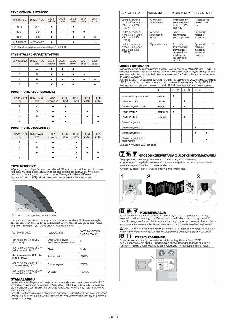
31 (31
TRYB CIŚNIENIA STAŁEGO
UPM3 xx-50 UPM3 xx-70 LED1zielona
LED2żółta
LED3żółta
LED4żółta
LED5żółta
CP1 CP1 ● ●
CP2 CP2 ● ● ●
CP3 CP3 ● ● ● ●
AUTOADAPT AUTOADAPT ● ● ●
CP: charakterystyka ciśnienia stałego: 1, 2 lub 3.
TRYB STAŁEJ CHARAKTERYSTYKI
UPM3 xx-50(m)
UPM3 xx-70(m)
LED1zielona
LED2żółta
LED3żółta
LED4żółta
LED5żółta
2 4 ● ● ●
3 5 ● ● ● ●
4 6 ● ● ● ● ●
5 7 ● ● ● ●
PWM PROFIL A (OGRZEWANIE)
UPM3 xx-50(m)
UPM3 xx-70(m)
LED1czerwona
LED2żółta
LED3żółta
LED4żółta
LED5żółta
2 4 ● ●
3 5 ● ● ●
4 6 ● ● ● ●
5 7 ● ● ●
PWM PROFIL C (SOLARNY)
UPM3 xx-50(m)
UPM3 xx-70(m)
LED1czerwona
LED2żółta
LED3żółta
LED4żółta
LED5żółta
2 4 ● ●
3 5 ● ● ●
4 6 ● ● ● ●
5 7 ● ● ●
TRYB ROBOCZYW podglądzie wydajności pierwsza dioda LED jest zawsze zielona, jeżeli nie ma alarmów. W podglądzie ustawień może być zielona lub czerwona, wskazując sterowanie wewnętrzne lub zewnętrzne. Cztery żółte diody LED wskazują wydajność pompy (P1) tak jak pokazano na rysunku i w tabeli poniżej.
100 %
75 %
50 %
25 %
Obszar roboczy zgodnie z obciążeniem
Kiedy aktywny jest tryb roboczy, wszystkie aktywne diody LED świecą ciągle, aby odróżnić ten tryb od trybu wyboru ustawień. Jeśli pompa jest zatrzymana sygnałem zewnętrznym, dioda LED 1 miga na zielono.
WYŚWIETLACZ WSKAZANIE WYDAJNOŚĆ W % Z P1 MAKS.
Jedna zielona dioda LED (migająca)
Oczekiwanie (tylko sterowanie zewnętrzne) 0
Jedna zielona dioda LED + jedna żółta dioda LED Niski 0-25
Jedna zielona dioda LED + dwie żółte diody LED Średni niski 25-50
Jedna zielona dioda LED + trzy żółte diody LED Średni wysoki 50-75
Jedna zielona dioda LED + cztery żółte diody LED Wysoki 75-100
STAN ALARMUJeśli urządzenie obiegowe wykryje jeden lub więcej alarmów, dwukolorowa dioda LED 1 zmieni kolor z zielonego na czerwony. Kiedy alarm jest aktywny, diody LED wskazują typ alarmu zgodnie z zestawieniem w poniższej tabeli. Jeśli w tym samym czasie aktywnych jest kilka alarmów,diody LED wskażą tylko błąd o najwyższym priorytecie. Priorytet jest określony kolejnością w tabeli. Kiedy nie ma już aktywnych alarmów, interfejs użytkownika przełączy się ponownie do trybu roboczego.
WYŚWIETLACZ WSKAZANIE PRACA POMPY ROZWIĄZANIE
Jedna czerwona dioda LED + jedna żółta dioda LED (LED 5)
Wirnik jest zablokowany
Próba ponow-nego uruchom-ienia co 1,33 sekundy.
Poczekać lub odblokować wał.
Jedna czerwona dioda LED + jedna żółta dioda LED (LED 4)
Napięcie zasilające za niskie.
Tylko ostrzeżenie, pompa pracuje.
Sprawdzić napięcie zasilające.
Jedna czerwona dioda LED + jedna żółta dioda LED (LED 3)
Błąd elektryczny. Pompa jest zatrzymana z powodu nisk-iego napięcia zasilającego lub poważnej usterki.
Sprawdzić napięcie zasilające/wymienić pompę.
WIDOK USTAWIEŃNaciskając przycisk, można przejść z widoku wydajności do widoku ustawień. Diody LED wskazują aktualne ustawienie. Widok ustawień wskazuje, w jakim trybie pracuje pompa. Na tym etapie nie można zmienić żadnych ustawień. Po 2 sekundach wyświetlacz wróci do widoku wydajności.Jeśli dioda LED 1 jest zielona, oznacza to pracę lub sterowanie wewnętrzne. Jeśli dioda LED 1 jest czerwona, oznacza to alarm lub sterowanie zewnętrzne. Diody LED 2 i 3 wskazują różne tryby sterowania, a diody LED 4 i 5 wskazują różne charakterystyki.
LED 1 LED 2 LED 3 LED 4 LED 5
Ciśnienie proporcjonalne zielona ●
Ciśnienie stałe zielona ●
Charakterystyka stała zielona ● ●
PWM Profil A czerwona ●
PWM Profil C czerwona ●
Charakterystyka 1
Charakterystyka 2 ●
Charakterystyka 3 ● ●
Charakterystyka 4/AUTOADAPT
●
Uwaga: ● = Dioda LED jest żółta.
SPOSÓB KORZYSTANIA Z ULOTKI INFORMACYJNEJDo grupy pompowej dołączono ulotkę informacyjną, w której obrazowo przedstawiono, do jakich zastosowań nadaje się ta jednostka. Można tam również wpisać uwagi oraz zostawić swoją wizytówkę.
Wystarczy zdjąć osłonę i wybrać odpowiednie informacje.
KONSERWACJAW normalnych warunkach jednostka cyrkulacyjna nie jest poddawana żadnym czynnościom konserwacyjnym. Ważne jest jednak, aby co roku przeprowadzić kontrolę całego systemu. Należy zwrócić szczególną uwagę na wszystkie przyłącza gwintowane i spawane, a także na miejsca, w których może osadzać się kamień.
OSTRZEŻENIE! Przed podjęciem jakichkolwiek działań należy odłączyć zasilanie elektryczne. Należy również uważać na ciepłą wodę znajdującą się w urządzeniu.
CZĘŚCI ZAMIENNECzęści zamienne należy zamawiać w dziale obsługi klienta firmy ESBE. W celu usprawnienia obsługi i uniknięcia nieprawidłowości podczas składania zamówień należy podać wszystkie dane widoczne na tabliczce znamionowej.
GXX X00

www.esbe.eu
Mtrl.nr. 98140917 • Ritn.nr. 7553 utg. B • Rev. 1512
DE IT FR PLGB SE


![Describing Services for Service Ecosystemsdisi.unitn.it/~dandrea/ESBE/papers/esbe08_submission_6.pdf · Web services [34] for heterogeneous application integration and communication](https://img.pdfslide.us/doc/110x75/5f83529382c9fb0f8f5df210/describing-services-for-service-dandreaesbepapersesbe08submission6pdf-web.jpg)