Embed Size (px)
Citation preview
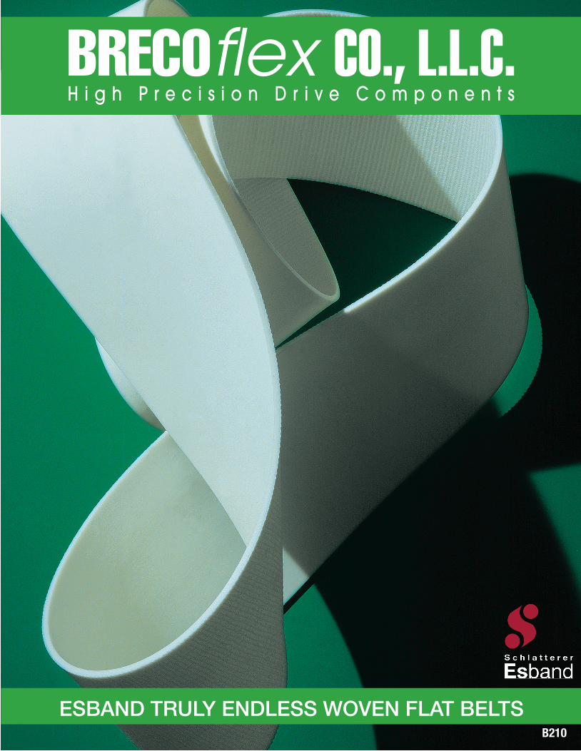
ESBAND TRULY ENDLESS WOVEN FLAT BELTSB210
Final_B210 Cover.indd 1 6/23/15 10:17 AM
Endless
2
TRULY ENDLESS FLAT BELTS DEFINED:ESBAND truly endless homogeneous flat belts are manufactured without joints or splices for high-performance drive and
conveying applications. These unique flat belts offer many advantages and benefits for demanding drive and conveying
machinery and equipment. ESBAND endless belt technology outperforms conventional joined flat belt designs.
CHARACTERISTICS• Homogeneous
Uniform elongation, tear resistance and thickness
tolerances over the entire belt length – weak points
are eliminated
• Flexible
Reliable for frequent back bending. Also suited for very
small pulley and shaft diameters as well as knife edges.
• Quiet running
Low noise level due to truly endless design (no joints)
• Reduced preload
The bipolar design: Low longitudinal elongation and high
transverse flexibility result in reduced pretension and low
shaft loading
• Customized
Wide selection of materials for carcass and covers allows
for customer specific belt configurations to meet unique
needs
ADVANTAGES• Highly efficient
(> 98.5%)
• Belt speeds of 150 m/s possible
• Long service life
• High loads possible
(up to 30 kW/cm)
• Good dynamic characteristics
• Improved shock absorption
• Can be used as overload protection
PRODUCTS & PROPERTIES• Drive belts
High running accuracy, low vibration, flexible
• Standard Conveyor belts
Tear-resistant, elastic, customized
• Weighing belts
Homogeneous, constant weight, reliable
• Vacuum conveyor belts
Precise, perforated, customized
• Food transport belts
Easy to clean, temperature resistant
• High temperature belts
Reliable in temperature ranges up to 300°C
• Machine and process belts
Robust, reliable, durable
• Special belts (to customer’s specifications)
Diverse, unique, solution-oriented
• Conveyor belts for paper transport and paper handling
Abrasion-resistant, ozone-resistant, customized
• Coating materials for timing and Multi-V belts
Application specific, innovative
TABLE OF CONTENTSGeneral Information
Drives . . . . . . . . . . . . . . . . . . . . . . . . . . . . . . . . . . . . . . . . . .3
Conveying . . . . . . . . . . . . . . . . . . . . . . . . . . . . . . . . . . . . . .3
Carcass Materials . . . . . . . . . . . . . . . . . . . . . . . . . . . . . . . .4
Coating Materials . . . . . . . . . . . . . . . . . . . . . . . . . . . . . . . .5
Coefficients of Friction . . . . . . . . . . . . . . . . . . . . . . . . . . . .6
Special Processing . . . . . . . . . . . . . . . . . . . . . . . . . . . . . . . .7
Technical Specifications
Polyurethane . . . . . . . . . . . . . . . . . . . . . . . . . . . . . . . . . . . .8
Neoprene . . . . . . . . . . . . . . . . . . . . . . . . . . . . . . . . . . . . .10
FX-Polyurethane / Silicone / PVC . . . . . . . . . . . . . . . . . . .12
Design Considerations
Design Considerations . . . . . . . . . . . . . . . . . . . . . . . . . . . .14
Drive Layout . . . . . . . . . . . . . . . . . . . . . . . . . . . . . . . . . . . .15
Belt Sizing . . . . . . . . . . . . . . . . . . . . . . . . . . . . . . . . . . . . . .16
Duty Cycle . . . . . . . . . . . . . . . . . . . . . . . . . . . . . . . . . . . . .16
Power and belt speed . . . . . . . . . . . . . . . . . . . . . . . . . . .16
Bending frequency . . . . . . . . . . . . . . . . . . . . . . . . . . . . . .17
Special drive designs . . . . . . . . . . . . . . . . . . . . . . . . . . . .17
Belt Examples
Belt Examples . . . . . . . . . . . . . . . . . . . . . . . . . . . . . . . . . . .18
All recommendations for the use of the products described
herein and all other data or information set forth in this
publication, whether concerning such products or
otherwise, are furnished without any guarantee, warranty
representations or inducement of any kind whether express
or implied, including but not limited to warranties of
merchantability and fitness for a particular purpose.
BRECOflex CO., L.L.C. expressly disclaims liability under any
theory, including without limitation, contract negligence,
misrepresentation or breach of any obligation relating to
the recommendation, data or information set forth herein.
Readers and customers are encouraged to conduct their
own test before using any product. Read its label and all
related instructions.
Drives & Conveying
3
1
CONVEYING
3 4 5
DRIVES
2
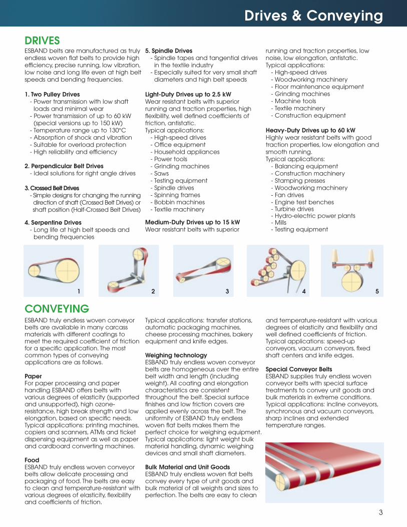
ESBAND belts are manufactured as trulyendless woven flat belts to provide highefficiency, precise running, low vibration,low noise and long life even at high beltspeeds and bending frequencies.
1. Two Pulley Drives- Power transmission with low shaft
loads and minimal wear- Power transmission of up to 60 kW
(special versions up to 150 kW)- Temperature range up to 130°C- Absorption of shock and vibration- Suitable for overload protection- High reliability and efficiency
2. Perpendicular Belt Drives- Ideal solutions for right angle drives
3. Crossed Belt Drives- Simple designs for changing the runningdirection of shaft (Crossed Belt Drives) orshaft position (Half-Crossed Belt Drives)
4. Serpentine Drives- Long life at high belt speeds and
bending frequencies
5. Spindle Drives- Spindle tapes and tangential drives
in the textile industry- Especially suited for very small shaft
diameters and high belt speeds
Light-Duty Drives up to 2.5 kWWear resistant belts with superiorrunning and traction properties, highflexibility, well defined coefficients offriction, antistatic.Typical applications:
- High-speed drives- Office equipment- Household appliances- Power tools- Grinding machines- Saws- Testing equipment- Spindle drives- Spinning frames- Bobbin machines- Textile machinery
Medium-Duty Drives up to 15 kWWear resistant belts with superior
running and traction properties, lownoise, low elongation, antistatic.Typical applications:
- High-speed drives- Woodworking machinery- Floor maintenance equipment- Grinding machines- Machine tools- Textile machinery- Construction equipment
Heavy-Duty Drives up to 60 kWHighly wear resistant belts with goodtraction properties, low elongation andsmooth running.Typical applications:
- Balancing equipment- Construction machinery- Stamping presses- Woodworking machinery- Fan drives- Engine test benches- Turbine drives- Hydro-electric power plants- Mills- Testing equipment
ESBAND truly endless woven conveyorbelts are available in many carcassmaterials with different coatings tomeet the required coefficient of frictionfor a specific application. The mostcommon types of conveyingapplications are as follows.
PaperFor paper processing and paperhandling ESBAND offers belts withvarious degrees of elasticity (supportedand unsupported), high ozone-resistance, high break strength and lowelongation, based on specific needs.Typical applications: printing machines,copiers and scanners, ATMs and ticketdispensing equipment as well as paperand cardboard converting machines.
FoodESBAND truly endless woven conveyorbelts allow delicate processing andpackaging of food. The belts are easyto clean and temperature-resistant with various degrees of elasticity, flexibilityand coefficients of friction.
Typical applications: transfer stations,automatic packaging machines,cheese processing machines, bakeryequipment and knife edges.
Weighing technologyESBAND truly endless woven conveyorbelts are homogeneous over the entirebelt width and length (includingweight). All coating and elongationcharacteristics are consistentthroughout the belt. Special surfacefinishes and low friction covers areapplied evenly across the belt. Theuniformity of ESBAND truly endlesswoven flat belts makes them theperfect choice for weighing equipment.Typical applications: light weight bulkmaterial handling, dynamic weighingdevices and small shaft diameters.
Bulk Material and Unit GoodsESBAND truly endless woven flat beltsconvey every type of unit goods andbulk material of all weights and sizes toperfection. The belts are easy to clean
and temperature-resistant with variousdegrees of elasticity and flexibility andwell defined coefficients of friction.Typical applications: speed-upconveyors, vacuum conveyors, fixedshaft centers and knife edges.
Special Conveyor BeltsESBAND supplies truly endless wovenconveyor belts with special surfacetreatments to convey unit goods andbulk materials in extreme conditions.Typical applications: incline conveyors,synchronous and vacuum conveyors,sharp inclines and extendedtemperature ranges.
Carcass Materials
4
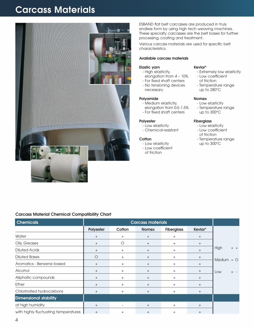
ESBAND flat belt carcasses are produced in truly
endless form by using high tech weaving machines.
These specialty carcasses are the belt bases for further
processing, coating and treatment.
Various carcass materials are used for specific belt
characteristics.
Available carcass materials
Elastic yarn- High elasticity,
elongation from 4 – 10%- For fixed shaft centers- No tensioning devices
necessary
Polyamide- Medium elasticity,
elongation from 0.5-1.5%- For fixed shaft centers
Polyester- Low elasticity- Chemical-resistant
Cotton- Low elasticity- Low coefficient
of friction
Kevlar®
- Extremely low elasticity- Low coefficient
of friction- Temperature range
up to 280°C
Nomex- Low elasticity- Temperature range
up to 300°C
Fiberglass- Low elasticity- Low coefficient
of friction- Temperature range
up to 300°C
Chemicals Carcass materials
Polyester Cotton Nomex Fiberglass Kevlar®
Water + + + + +
Oils, Greases + O + + +
Diluted Acids + + + + +
Diluted Bases O + + + +
Aromatics - Benzene based + + + + +
Alcohol + + + + +
Aliphatic compounds + + + + +
Ether + + + + +
Chlorinated hydrocarbons + + + + +
Dimensional stability
at high humidity + - + + +
with highly fluctuating temperatures + + + + +
High = +
Medium = O
Low = -
Carcass Material Chemical Compatibility Chart
Coating Materials
5
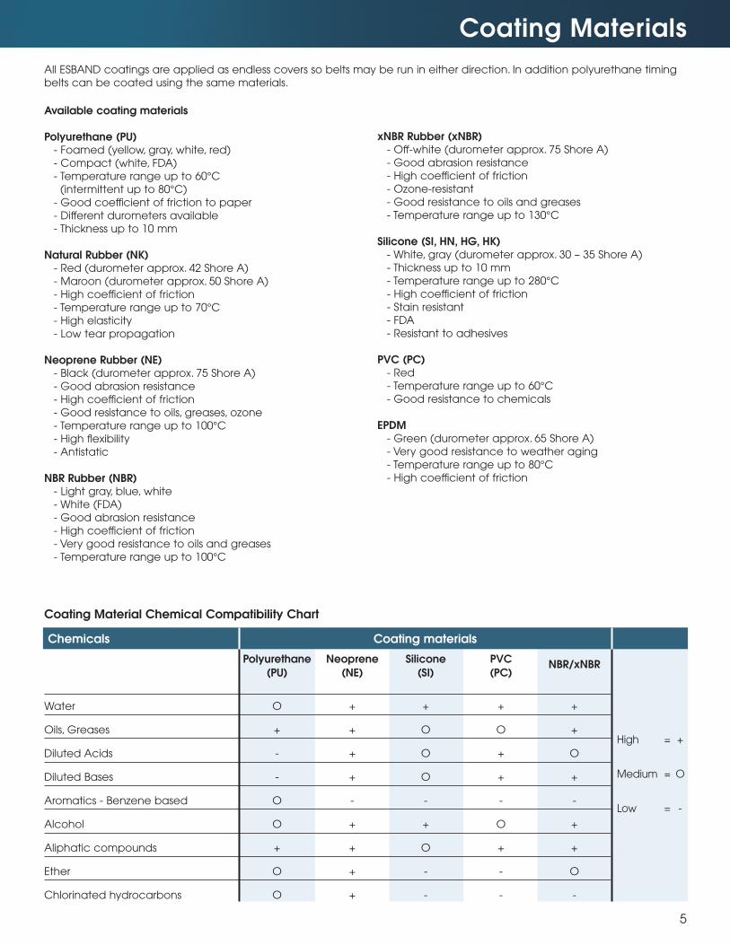
Chemicals Coating materials
Polyurethane Neoprene Silicone PVC
(PU) (NE) (SI) (PC)NBR/xNBR
Water O + + + +
Oils, Greases + + O O +
Diluted Acids - + O + O
Diluted Bases - + O + +
Aromatics - Benzene based O - - - -
Alcohol O + + O +
Aliphatic compounds + + O + +
Ether O + - - O
Chlorinated hydrocarbons O + - - -
High = +
Medium = O
Low = -
Available coating materials
Polyurethane (PU)- Foamed (yellow, gray, white, red)
- Compact (white, FDA)
- Temperature range up to 60°C
(intermittent up to 80°C)
- Good coefficient of friction to paper
- Different durometers available
- Thickness up to 10 mm
Natural Rubber (NK)- Red (durometer approx. 42 Shore A)
- Maroon (durometer approx. 50 Shore A)
- High coefficient of friction
- Temperature range up to 70°C
- High elasticity
- Low tear propagation
Neoprene Rubber (NE)- Black (durometer approx. 75 Shore A)
- Good abrasion resistance
- High coefficient of friction
- Good resistance to oils, greases, ozone
- Temperature range up to 100°C
- High flexibility
- Antistatic
NBR Rubber (NBR)- Light gray, blue, white
- White (FDA)
- Good abrasion resistance
- High coefficient of friction
- Very good resistance to oils and greases
- Temperature range up to 100°C
xNBR Rubber (xNBR)- Off-white (durometer approx. 75 Shore A)
- Good abrasion resistance
- High coefficient of friction
- Ozone-resistant
- Good resistance to oils and greases
- Temperature range up to 130°C
Silicone (SI, HN, HG, HK)- White, gray (durometer approx. 30 – 35 Shore A)
- Thickness up to 10 mm
- Temperature range up to 280°C
- High coefficient of friction
- Stain resistant
- FDA
- Resistant to adhesives
PVC (PC)- Red
- Temperature range up to 60°C
- Good resistance to chemicals
EPDM- Green (durometer approx. 65 Shore A)
- Very good resistance to weather aging
- Temperature range up to 80°C
- High coefficient of friction
All ESBAND coatings are applied as endless covers so belts may be run in either direction. In addition polyurethane timing
belts can be coated using the same materials.
Coating Material Chemical Compatibility Chart
Coefficients of Friction
6
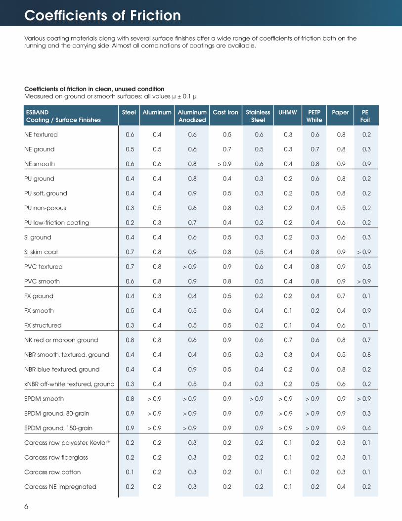
Various coating materials along with several surface finishes offer a wide range of coefficients of friction both on the
running and the carrying side. Almost all combinations of coatings are available.
ESBAND Steel Aluminum Aluminum Cast Iron Stainless UHMW PETP Paper PE
Coating / Surface Finishes Anodized Steel White Foil
NE textured 0.6 0.4 0.6 0.5 0.6 0.3 0.6 0.8 0.2
NE ground 0.5 0.5 0.6 0.7 0.5 0.3 0.7 0.8 0.3
NE smooth 0.6 0.6 0.8 > 0.9 0.6 0.4 0.8 0.9 0.9
PU ground 0.4 0.4 0.8 0.4 0.3 0.2 0.6 0.8 0.2
PU soft, ground 0.4 0.4 0.9 0.5 0.3 0.2 0.5 0.8 0.2
PU non-porous 0.3 0.5 0.6 0.8 0.3 0.2 0.4 0.5 0.2
PU low-friction coating 0.2 0.3 0.7 0.4 0.2 0.2 0.4 0.6 0.2
SI ground 0.4 0.4 0.6 0.5 0.3 0.2 0.3 0.6 0.3
SI skim coat 0.7 0.8 0.9 0.8 0.5 0.4 0.8 0.9 > 0.9
PVC textured 0.7 0.8 > 0.9 0.9 0.6 0.4 0.8 0.9 0.5
PVC smooth 0.6 0.8 0.9 0.8 0.5 0.4 0.8 0.9 > 0.9
FX ground 0.4 0.3 0.4 0.5 0.2 0.2 0.4 0.7 0.1
FX smooth 0.5 0.4 0.5 0.6 0.4 0.1 0.2 0.4 0.9
FX structured 0.3 0.4 0.5 0.5 0.2 0.1 0.4 0.6 0.1
NK red or maroon ground 0.8 0.8 0.6 0.9 0.6 0.7 0.6 0.8 0.7
NBR smooth, textured, ground 0.4 0.4 0.4 0.5 0.3 0.3 0.4 0.5 0.8
NBR blue textured, ground 0.4 0.4 0.9 0.5 0.4 0.2 0.6 0.8 0.2
xNBR off-white textured, ground 0.3 0.4 0.5 0.4 0.3 0.2 0.5 0.6 0.2
EPDM smooth 0.8 > 0.9 > 0.9 0.9 > 0.9 > 0.9 > 0.9 0.9 > 0.9
EPDM ground, 80-grain 0.9 > 0.9 > 0.9 0.9 0.9 > 0.9 > 0.9 0.9 0.3
EPDM ground, 150-grain 0.9 > 0.9 > 0.9 0.9 0.9 > 0.9 > 0.9 0.9 0.4
Carcass raw polyester, Kevlar® 0.2 0.2 0.3 0.2 0.2 0.1 0.2 0.3 0.1
Carcass raw fiberglass 0.2 0.2 0.3 0.2 0.2 0.1 0.2 0.3 0.1
Carcass raw cotton 0.1 0.2 0.3 0.2 0.1 0.1 0.2 0.3 0.1
Carcass NE impregnated 0.2 0.2 0.3 0.2 0.2 0.1 0.2 0.4 0.2
Coefficients of friction in clean, unused conditionMeasured on ground or smooth surfaces; all values µ ± 0.1 µ
Special Processing
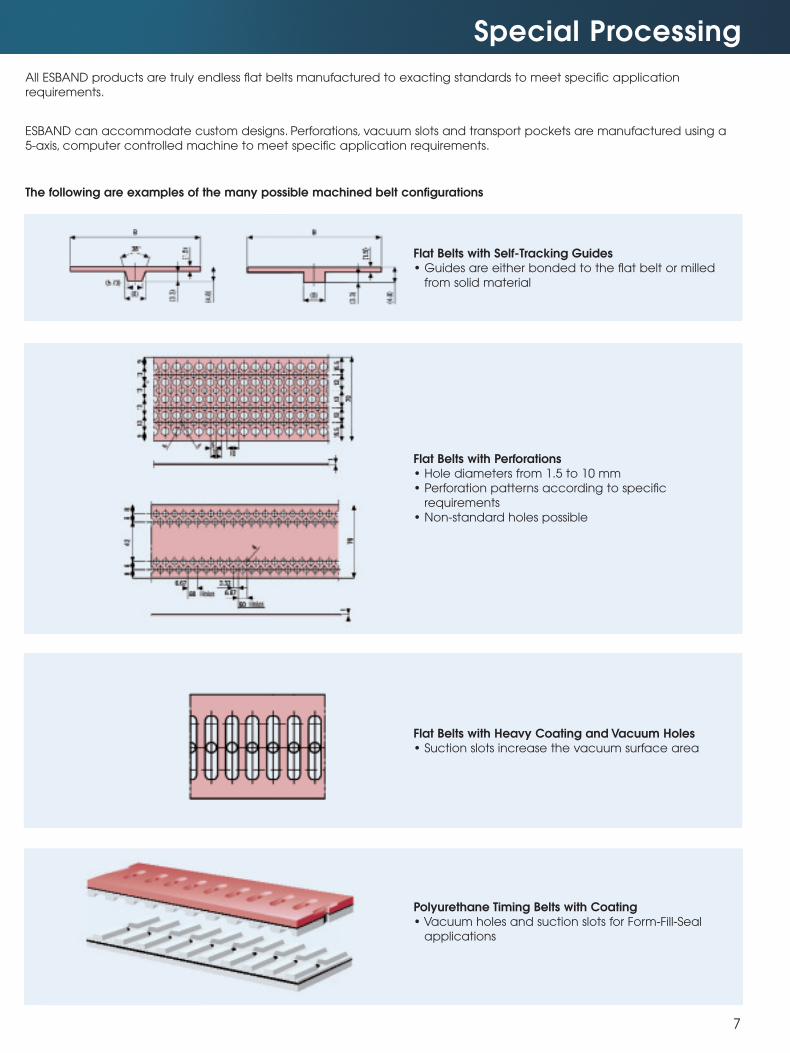
All ESBAND products are truly endless flat belts manufactured to exacting standards to meet specific application
requirements.
ESBAND can accommodate custom designs. Perforations, vacuum slots and transport pockets are manufactured using a
5-axis, computer controlled machine to meet specific application requirements.
The following are examples of the many possible machined belt configurations
7
Flat Belts with Self-Tracking Guides • Guides are either bonded to the flat belt or milled
from solid material
Flat Belts with Perforations• Hole diameters from 1.5 to 10 mm
• Perforation patterns according to specific
requirements
• Non-standard holes possible
Flat Belts with Heavy Coating and Vacuum Holes• Suction slots increase the vacuum surface area
Polyurethane Timing Belts with Coating• Vacuum holes and suction slots for Form-Fill-Seal
applications
PU
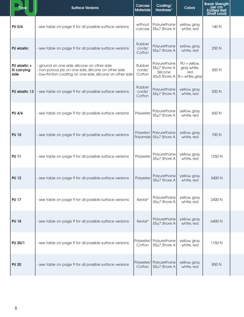
8
Type Surface VersionsCarcassMaterials
Coating/Hardness*
ColorsBreak Strength
per cmEndless Belt(Shaft Load)
- see table on page 9 for all possible surface versionswithoutcarcass
Polyurethane55±7 Shore A
yellow, gray,white, red
140 NPU 0/6
- see table on page 9 for all possible surface versionsRubbercords/Cotton
Polyurethane55±7 Shore A
yellow, gray,white, red
250 NPU elastic
- ground on one side, silicone on other side- non-porous ply on one side, silicone on other side- low-friction coating on one side, silicone on other side
Rubbercords/Cotton
Polyurethane55±7 Shore A
Silicone30±5 Shore A
PU = yellow,gray, white,
redSI = white, gray
300 NPU elastic +SI carryingside
- see table on page 9 for all possible surface versionsRubbercords/Cotton
Polyurethane55±7 Shore A
yellow, gray,white, red
200 NPU elastic 13
- see table on page 9 for all possible surface versions PolyesterPolyurethane55±7 Shore A
yellow, gray,white, red
650 NPU 4/6
- see table on page 9 for all possible surface versionsPolyester/Polyamide
Polyurethane55±7 Shore A
yellow, gray,white, red
700 NPU 10
- see table on page 9 for all possible surface versions PolyesterPolyurethane55±7 Shore A
yellow, gray,white, red
1250 NPU 11
- see table on page 9 for all possible surface versions PolyesterPolyurethane55±7 Shore A
yellow, gray,white, red
3400 NPU 12
- see table on page 9 for all possible surface versions Kevlar® Polyurethane55±7 Shore A
yellow, gray,white, red
2400 NPU 17
- see table on page 9 for all possible surface versions Kevlar® Polyurethane55±7 Shore A
yellow, gray,white, red
6400 NPU 18
- see table on page 9 for all possible surface versionsPolyester/
CottonPolyurethane55±7 Shore A
yellow, gray,white, red
1150 NPU 20/1
- see table on page 9 for all possible surface versionsPolyester/
CottonPolyurethane55±7 Shore A
yellow, gray,white, red
850 NPU 20
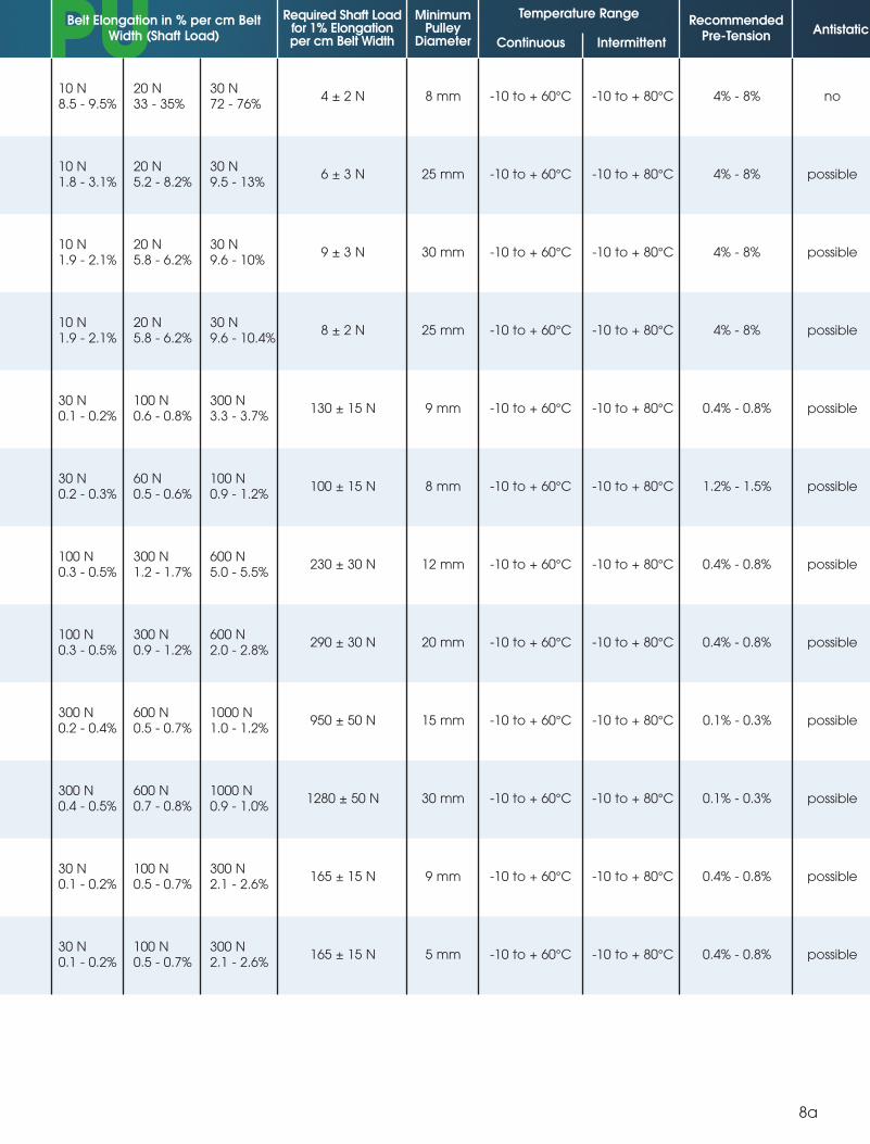
PUFX - SI - PCBelt Elongation in % per cm Belt
Width (Shaft Load)
Required Shaft Loadfor 1% Elongationper cm Belt Width
MinimumPulley
Diameter
Temperature RangeRecommended
Pre-Tension AntistaticContinuous Intermittent
10 N8.5 - 9.5%
20 N33 - 35%
30 N72 - 76%
4 ± 2 N 8 mm -10 to + 60°C -10 to + 80°C 4% - 8% no
10 N1.8 - 3.1%
20 N5.2 - 8.2%
30 N9.5 - 13%
6 ± 3 N 25 mm -10 to + 60°C -10 to + 80°C 4% - 8% possible
possible
possible
possible
possible
possible
possible
possible
possible
possible
possible
10 N1.9 - 2.1%
20 N5.8 - 6.2%
30 N9.6 - 10%
9 ± 3 N 30 mm -10 to + 60°C -10 to + 80°C 4% - 8%
10 N1.9 - 2.1%
20 N5.8 - 6.2%
30 N9.6 - 10.4%
300 N3.3 - 3.7%
100 N0.9 - 1.2%
600 N5.0 - 5.5%
600 N2.0 - 2.8%
1000 N1.0 - 1.2%
1000 N0.9 - 1.0%
300 N2.1 - 2.6%
300 N2.1 - 2.6%
8 ± 2 N 25 mm -10 to + 60°C -10 to + 80°C 4% - 8%
30 N0.1 - 0.2%
100 N0.6 - 0.8%
130 ± 15 N 9 mm -10 to + 60°C -10 to + 80°C 0.4% - 0.8%
30 N0.2 - 0.3%
60 N0.5 - 0.6%
100 ± 15 N 8 mm -10 to + 60°C -10 to + 80°C 1.2% - 1.5%
100 N0.3 - 0.5%
300 N1.2 - 1.7%
230 ± 30 N 12 mm -10 to + 60°C -10 to + 80°C 0.4% - 0.8%
100 N0.3 - 0.5%
300 N0.9 - 1.2%
290 ± 30 N 20 mm -10 to + 60°C -10 to + 80°C 0.4% - 0.8%
300 N0.2 - 0.4%
600 N0.5 - 0.7%
950 ± 50 N 15 mm -10 to + 60°C -10 to + 80°C 0.1% - 0.3%
300 N0.4 - 0.5%
600 N0.7 - 0.8%
1280 ± 50 N 30 mm -10 to + 60°C -10 to + 80°C 0.1% - 0.3%
30 N0.1 - 0.2%
100 N0.5 - 0.7%
165 ± 15 N 9 mm -10 to + 60°C -10 to + 80°C 0.4% - 0.8%
30 N0.1 - 0.2%
100 N0.5 - 0.7%
165 ± 15 N 5 mm -10 to + 60°C -10 to + 80°C 0.4% - 0.8%
8a
PUPUFX - SI - PC
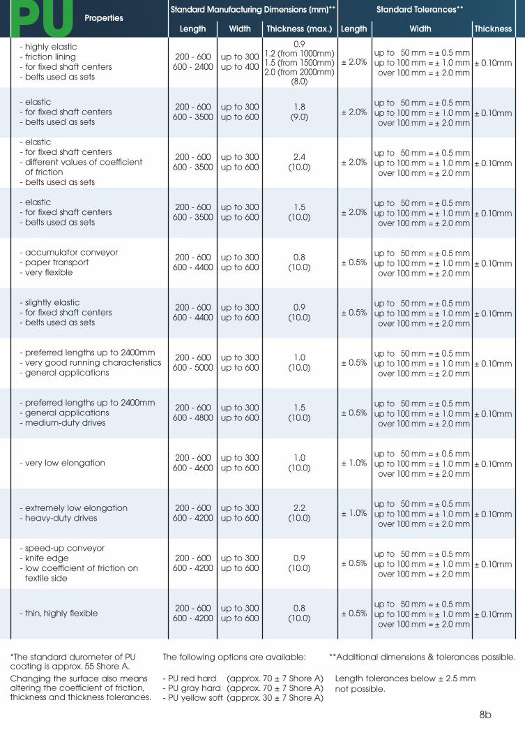
*The standard durometer of PUcoating is approx. 55 Shore A.
Changing the surface also meansaltering the coefficient of friction,thickness and thickness tolerances.
The following options are available:
- PU red hard (approx. 70 ± 7 Shore A)- PU gray hard (approx. 70 ± 7 Shore A)- PU yellow soft (approx. 30 ± 7 Shore A)
**Additional dimensions & tolerances possible.
Length tolerances below ± 2.5 mm
not possible.
Antistatic PropertiesStandard Manufacturing Dimensions [mm]** Standard Tolerances**
Length WidthThickness (max.)
- highly elastic- friction lining- for fixed shaft centers- belts used as sets
200 - 600600 - 2400
up to 300up to 400
0.91.2 (from 1000mm)1.5 (from 1500mm)2.0 (from 2000mm)
(8.0)
± 2.0%up to 50 mm = ± 0.5 mmup to 100 mm = ± 1.0 mmover 100 mm = ± 2.0 mm
- elastic- for fixed shaft centers- belts used as sets
200 - 600600 - 3500
up to 300up to 600
1.8(9.0)
± 2.0%
- elastic- for fixed shaft centers- different values of coefficient
of friction- belts used as sets
200 - 600600 - 3500
up to 300up to 600
2.4(10.0)
± 2.0%
- elastic- for fixed shaft centers- belts used as sets
200 - 600600 - 3500
up to 300up to 600
1.5(10.0)
± 2.0%
- accumulator conveyor- paper transport- very flexible
200 - 600600 - 4400
up to 300up to 600
0.8(10.0)
± 0.5%
- slightly elastic- for fixed shaft centers- belts used as sets
200 - 600600 - 4400
up to 300up to 600
0.9(10.0)
± 0.5%
- preferred lengths up to 2400mm- very good running characteristics- general applications
200 - 600600 - 5000
up to 300up to 600
1.0(10.0)
± 0.5%
- preferred lengths up to 2400mm- general applications- medium-duty drives
200 - 600600 - 4800
up to 300up to 600
1.5(10.0)
± 0.5%
- very low elongation200 - 600
600 - 4600up to 300up to 600
1.0(10.0)
± 1.0%
- extremely low elongation- heavy-duty drives
200 - 600600 - 4200
up to 300up to 600
2.2(10.0)
± 1.0%
- speed-up conveyor- knife edge- low coefficient of friction on
textile side
200 - 600600 - 4200
up to 300up to 600
0.9(10.0)
± 0.5%
- thin, highly flexible200 - 600
600 - 4200up to 300up to 600
0.8(10.0)
± 0.5%
8b
± 0.10mm
up to 50 mm = ± 0.5 mmup to 100 mm = ± 1.0 mmover 100 mm = ± 2.0 mm
± 0.10mm
up to 50 mm = ± 0.5 mmup to 100 mm = ± 1.0 mmover 100 mm = ± 2.0 mm
± 0.10mm
up to 50 mm = ± 0.5 mmup to 100 mm = ± 1.0 mmover 100 mm = ± 2.0 mm
± 0.10mm
up to 50 mm = ± 0.5 mmup to 100 mm = ± 1.0 mmover 100 mm = ± 2.0 mm
± 0.10mm
up to 50 mm = ± 0.5 mmup to 100 mm = ± 1.0 mmover 100 mm = ± 2.0 mm
± 0.10mm
up to 50 mm = ± 0.5 mmup to 100 mm = ± 1.0 mmover 100 mm = ± 2.0 mm
± 0.10mm
up to 50 mm = ± 0.5 mmup to 100 mm = ± 1.0 mmover 100 mm = ± 2.0 mm
± 0.10mm
up to 50 mm = ± 0.5 mmup to 100 mm = ± 1.0 mmover 100 mm = ± 2.0 mm
± 0.10mm
up to 50 mm = ± 0.5 mmup to 100 mm = ± 1.0 mmover 100 mm = ± 2.0 mm
± 0.10mm
up to 50 mm = ± 0.5 mmup to 100 mm = ± 1.0 mmover 100 mm = ± 2.0 mm
± 0.10mm
up to 50 mm = ± 0.5 mmup to 100 mm = ± 1.0 mmover 100 mm = ± 2.0 mm
± 0.10mm
ThicknessLength Width
9
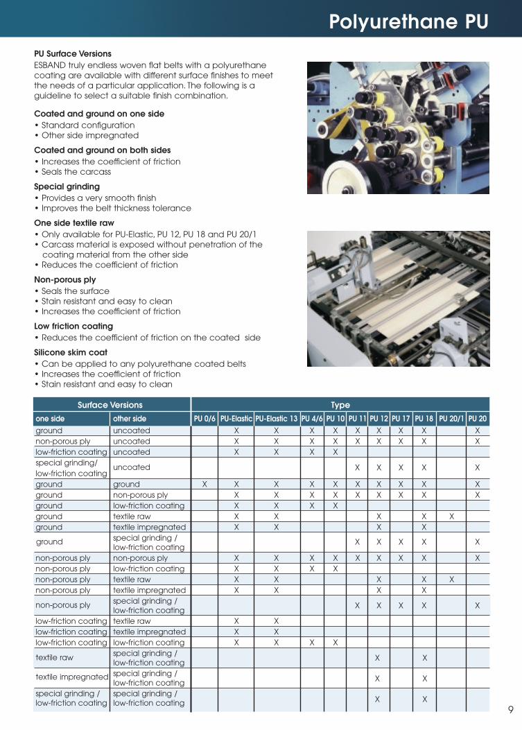
Polyurethane PU
PU Surface Versions
ESBAND truly endless woven flat belts with a polyurethane
coating are available with different surface finishes to meet
the needs of a particular application. The following is a
guideline to select a suitable finish combination.
Coated and ground on one side
• Standard configuration
• Other side impregnated
Coated and ground on both sides
• Increases the coefficient of friction
• Seals the carcass
Special grinding
• Provides a very smooth finish
• Improves the belt thickness tolerance
One side textile raw
• Only available for PU-Elastic, PU 12, PU 18 and PU 20/1
• Carcass material is exposed without penetration of the
coating material from the other side
• Reduces the coefficient of friction
Non-porous ply
• Seals the surface
• Stain resistant and easy to clean
• Increases the coefficient of friction
Low friction coating
• Reduces the coefficient of friction on the coated side
Silicone skim coat
• Can be applied to any polyurethane coated belts
• Increases the coefficient of friction
• Stain resistant and easy to clean
Surface Versions Type
one side other side PU 0/6 PU-Elastic PU-Elastic 13 PU 4/6 PU 10 PU 11 PU 12 PU 17 PU 18 PU 20/1 PU 20
ground uncoated X X X X X X X X X
non-porous ply uncoated X X X X X X X X X
low-friction coating uncoated X X X X
special grinding/
low-friction coating
ground ground X X X X X X X X X X
ground non-porous ply X X X X X X X X X
ground low-friction coating X X X X
ground textile raw X X X X X
ground textile impregnated X X X X
special grinding /low-friction coating
non-porous ply non-porous ply X X X X X X X X X
non-porous ply low-friction coating X X X X
non-porous ply textile raw X X X X X
non-porous ply textile impregnated X X X X
special grinding /low-friction coating
low-friction coating textile raw X X
low-friction coating textile impregnated X X
low-friction coating low-friction coating X X X X
special grinding /low-friction coating
special grinding /low-friction coating
special grinding / special grinding /low-friction coating low-friction coating
X X X X X
X X X X X
X X X X X
uncoated
ground
textile raw
non-porous ply
textile impregnated
X X
X X
X X
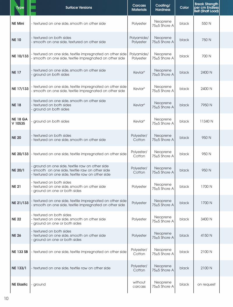
NE
10
NE Mini
Type Surface VersionsCarcassMaterials
Coating/Hardness
ColorBreak Strengthper cm EndlessBelt (Shaft Load)
- textured on one side, smooth on other side PolyesterNeoprene
75±5 Shore Ablack 550 N
NE 10- textured on both sides- smooth on one side, textured on other side
Polyamide/Polyester
Neoprene75±5 Shore A
black 750 N
NE 10/133 - textured on one side, textile impregnated on other side- smooth on one side, textile impregnated on other side
Polyamide/Polyester
Neoprene75±5 Shore A
black 700 N
NE 17- textured on one side, smooth on other side- ground on both sides
Kevlar® Neoprene75±5 Shore A
black 2400 N
NE 17/133- textured on one side, textile impregnated on other side- smooth on one side, textile impregnated on other side
Kevlar® Neoprene75±5 Shore A
black 2400 N
NE 18- textured on one side, smooth on other side- textured on both sides- ground on both sides
Kevlar® Neoprene75±5 Shore A
black 7950 N
NE 18 GAV 10535
- ground on both sides Kevlar® Neoprene75±5 Shore A
black 11340 N
NE 20- textured on both sides- textured on one side, smooth on other side
Polyester/Cotton
Neoprene75±5 Shore A
black 950 N
NE 20/133 - textured on one side, textile impregnated on other sidePolyester/
CottonNeoprene
75±5 Shore Ablack 950 N
NE 20/1- ground on one side, textile raw on other side- smooth on one side, textile raw on other side- textured on one side, textile raw on other side
Polyester/Cotton
Neoprene75±5 Shore A
black 950 N
NE 21- textured on both sides- textured on one side, smooth on other side- ground on one or both sides
PolyesterNeoprene
75±5 Shore Ablack 1700 N
NE 21/133- textured on one side, textile impregnated on other side- smooth on one side, textile impregnated on other side
PolyesterNeoprene
75±5 Shore Ablack 1700 N
NE 22- textured on both sides- textured on one side, smooth on other side- ground on one or both sides
PolyesterNeoprene
75±5 Shore Ablack 3400 N
NE 26- textured on both sides- textured on one side, smooth on other side- ground on one or both sides
PolyesterNeoprene
75±5 Shore Ablack 4150 N
NE 133 SB - textured on one side, textile impregnated on other sidePolyester/
CottonNeoprene
75±5 Shore Ablack 2100 N
NE 133/1 - textured on one side, textile raw on other sidePolyester/
CottonNeoprene
75±5 Shore Ablack 2100 N
NE Elastic - groundwithoutcarcass
Neoprene75±5 Shore A
black on request
NE NE
10a
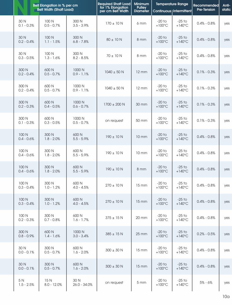
30 N0.1 - 0.3%
100 N0.5 - 0.7%
300 N3.5 - 3.9%
170 ± 10 N 6 mm-20 to
+100°C-25 to
+140°C0.4% - 0.8% yes
30 N0.2 - 0.4%
100 N1.1 - 1.5%
300 N6.8 - 7.8%
80 ± 10 N 8 mm-20 to
+100°C-25 to
+140°C0.4% - 0.8% yes
30 N0.3 - 0.5%
100 N1.3 - 1.6%
300 N8.2 - 8.5%
70 ± 10 N 8 mm-20 to
+100°C-25 to
+140°C0.4% - 0.8% yes
300 N0.2 - 0.4%
600 N0.5 - 0.7%
1000 N0.9 - 1.1%
1040 ± 50 N 12 mm-20 to
+100°C-25 to
+140°C0.1% - 0.3% yes
300 N0.2 - 0.4%
600 N0.5 - 0.7%
1000 N0.9 - 1.1%
1040 ± 50 N 12 mm-20 to
+100°C-25 to
+140°C0.1% - 0.3% yes
300 N0.2 - 0.3%
600 N0.4 - 0.5%
1000 N0.6 - 0.7%
1700 ± 200 N 30 mm-20 to
+100°C-25 to
+140°C0.1% - 0.3% yes
300 N0.1 - 0.3%
600 N0.3 - 0.5%
1000 N0.5 - 0.7%
on request 50 mm-20 to
+100°C-25 to
+140°C0.1% - 0.3% yes
100 N0.4 - 0.6%
300 N1.8 - 2.0%
600 N5.5 - 5.9%
190 ± 10 N 10 mm-20 to
+100°C-25 to
+140°C0.4% - 0.8% yes
100 N0.4 - 0.6%
300 N1.8 - 2.0%
600 N5.5 - 5.9%
190 ± 10 N 10 mm-20 to
+100°C-25 to
+140°C0.4% - 0.8% yes
100 N0.4 - 0.6%
300 N1.8 - 2.0%
600 N5.5 - 5.9%
190 ± 10 N 8 mm-20 to
+100°C-25 to
+140°C0.4% - 0.8% yes
100 N0.3 - 0.4%
300 N1.0 - 1.2%
600 N4.0 - 4.5%
270 ± 10 N 15 mm-20 to
+100°C-25 to
+140°C0.4% - 0.8% yes
100 N0.3 - 0.4%
300 N1.0 - 1.2%
600 N4.0 - 4.5%
270 ± 10 N 15 mm-20 to
+100°C-25 to
+140°C0.4% - 0.8% yes
100 N0.2 - 0.3%
300 N0.7 - 0.8%
600 N1.6 - 1.7%
375 ± 15 N 20 mm-20 to
+100°C-25 to
+140°C0.4% - 0.8% yes
300 N0.8 - 0.9%
600 N1.4 - 1.6%
1000 N3.0 - 3.4%
385 ± 15 N 25 mm-20 to
+100°C-25 to
+140°C0.2% - 0.5% yes
30 N0.0 - 0.1%
300 N0.5 - 0.7%
600 N1.6 - 2.0%
300 ± 30 N 15 mm-20 to
+100°C-25 to
+140°C0.4% - 0.8% yes
30 N0.0 - 0.1%
300 N0.5 - 0.7%
600 N1.6 - 2.0%
300 ± 30 N 15 mm-20 to
+100°C-25 to
+140°C0.4% - 0.8% yes
5 N1.5 - 2.5%
15 N8.0 - 12.0%
30 N26.0 - 34.0%
on request 5 mm-20 to
+100°C-25 to
+140°C5% - 6% yes
Belt Elongation in % per cm Belt Width (Shaft Load)
Required Shaft Loadfor 1% Elongationper cm Belt Width
MinimumPulley
Diameter
RecommendedPre-Tension
Anti-staticContinuous
Temperature Range
Intermittent
NE NE NE
10b
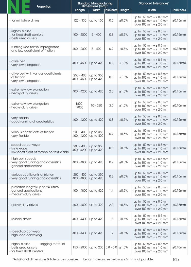
PropertiesStandard Manufacturing
Dimensions [mm]*Standard Tolerances*
Length Width Thickness Length Width Thickness
Anti-static
- for miniature drives 120 - 330 up to 150 0.5 ±0.5%up to 50 mm = ± 0.5 mmup to 100 mm = ± 1.0 mmover 100 mm = ± 2.0 mm
±0.15mm
- slightly elastic- for fixed shaft centers- belts used as sets
400 - 2000 5 - 420 0.8 ±0.5%up to 50 mm = ± 0.5 mmup to 100 mm = ± 1.0 mmover 100 mm = ± 2.0 mm
±0.15mm
- running side textile impregnated and low coefficient of friction
400 - 2000 5 - 420 0.7 ±0.5%up to 50 mm = ± 0.5 mmup to 100 mm = ± 1.0 mmover 100 mm = ± 2.0 mm
±0.15mm
- drive belt- very low elongation
400 - 4600 up to 420 0.9 ±1.0%up to 50 mm = ± 0.5 mmup to 100 mm = ± 1.0 mmover 100 mm = ± 2.0 mm
±0.15mm
- drive belt with various coefficientsof friction
- very low elongation
250 - 400400 - 4600
up to 350up to 420
0.8 ±1.0%up to 50 mm = ± 0.5 mmup to 100 mm = ± 1.0 mmover 100 mm = ± 2.0 mm
±0.15mm
- extremely low elongation- heavy-duty drives
400 - 4200 up to 420 2.0 ±1.0%up to 50 mm = ± 0.5 mmup to 100 mm = ± 1.0 mmover 100 mm = ± 2.0 mm
±0.15mm
- extremely low elongation- heavy-duty drives
1800 -9000
10 - 280 3.0 ±1.0%up to 50 mm = ± 0.5 mmup to 100 mm = ± 1.0 mmover 100 mm = ± 2.0 mm
±0.10mm
- very flexible- good running characteristics
400 - 4200 up to 420 0.8 ±0.5%up to 50 mm = ± 0.5 mmup to 100 mm = ± 1.0 mmover 100 mm = ± 2.0 mm
±0.15mm
- various coefficients of friction- very flexible
200 - 400400 - 4200
up to 350up to 400
0.7 ±0.5%up to 50 mm = ± 0.5 mmup to 100 mm = ± 1.0 mmover 100 mm = ± 2.0 mm
±0.15mm
- speed-up conveyor- knife edge- low coefficient of friction on textile side
200 - 400400 - 4200
up to 350up to 420
0.8 ±0.5%up to 50 mm = ± 0.5 mmup to 100 mm = ± 1.0 mmover 100 mm = ± 2.0 mm
±0.15mm
- high belt speeds- very good running characteristics- general applications
400 - 4800 up to 420 0.9 ±0.5%up to 50 mm = ± 0.5 mmup to 100 mm = ± 1.0 mmover 100 mm = ± 2.0 mm
±0.15mm
- various coefficients of friction- very good running characteristics
250 - 400400 - 4800
up to 350up to 420
0.8 ±0.5%up to 50 mm = ± 0.5 mmup to 100 mm = ± 1.0 mmover 100 mm = ± 2.0 mm
±0.15mm
- preferred lengths up to 2400mm- general applications- medium-duty drives
400 - 4800 up to 420 1.4 ±0.5%up to 50 mm = ± 0.5 mmup to 100 mm = ± 1.0 mmover 100 mm = ± 2.0 mm
±0.15mm
- heavy-duty drives 400 - 4800 up to 420 2.0 ±0.5%up to 50 mm = ± 0.5 mmup to 100 mm = ± 1.0 mmover 100 mm = ± 2.0 mm
±0.15mm
- spindle drives 400 - 4400 up to 420 1.3 ±0.5%up to 50 mm = ± 0.5 mmup to 100 mm = ± 1.0 mmover 100 mm = ± 2.0 mm
±0.15mm
- speed-up conveyor- high load conveying
400 - 4400
150 - 2000
up to 420
up to 200
1.2
0.8 - 5.0
±0.5%
±1.0%
up to 50 mm = ± 0.5 mmup to 100 mm = ± 1.0 mmover 100 mm = ± 2.0 mm
up to 50 mm = ± 0.5 mmup to 100 mm = ± 1.0 mmover 100 mm = ± 2.0 mm
±0.15mm
±0.10mm- highly elastic- belts used as sets- for fixed shaft centers
- lagging material
*Additional dimensions & tolerances possible. Length tolerances below ± 2.5 mm not possible.
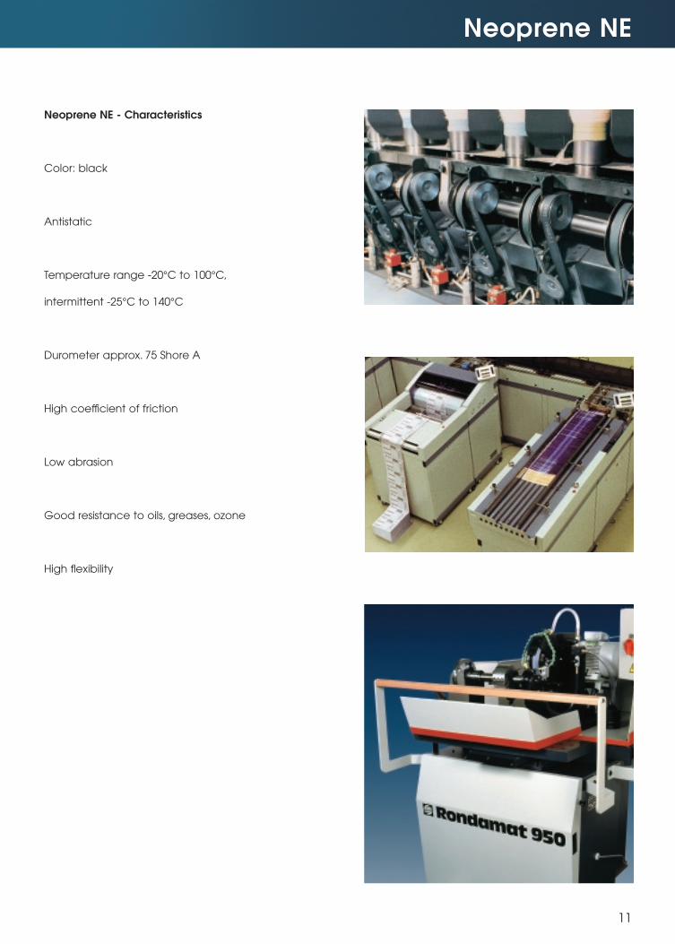
Neoprene NE
11
Neoprene NE - Characteristics
Color: black
Antistatic
Temperature range -20°C to 100°C,
intermittent -25°C to 140°C
Durometer approx. 75 Shore A
High coefficient of friction
Low abrasion
Good resistance to oils, greases, ozone
High flexibility
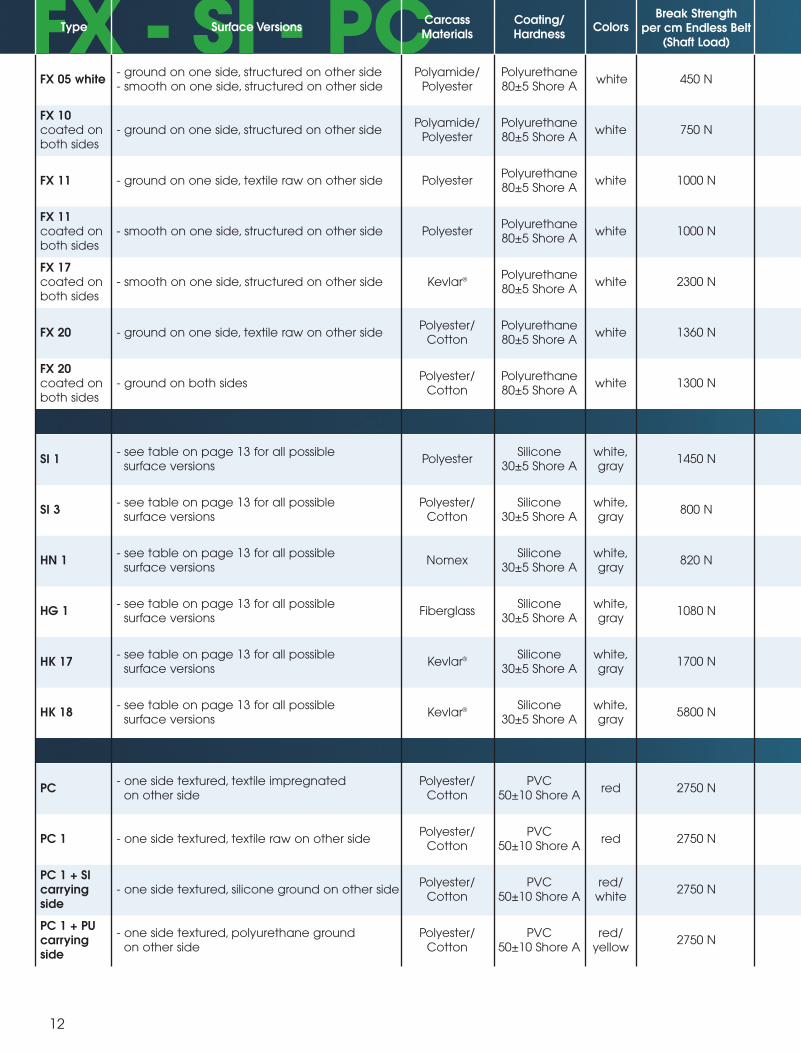
FX - SI - PC
12
Type Surface VersionsCarcassMaterials
Coating/Hardness
ColorsBreak Strength
per cm Endless Belt(Shaft Load)
FX 10coated onboth sides
- ground on one side, structured on other sidePolyamide/
PolyesterPolyurethane80±5 Shore A
white 750 N
FX 11 - ground on one side, textile raw on other side PolyesterPolyurethane80±5 Shore A
white 1000 N
FX 11coated onboth sides
- smooth on one side, structured on other side PolyesterPolyurethane80±5 Shore A
white 1000 N
FX 17coated onboth sides
- smooth on one side, structured on other side Kevlar® Polyurethane80±5 Shore A
white 2300 N
FX 20 - ground on one side, textile raw on other sidePolyester/
CottonPolyurethane80±5 Shore A
white 1360 N
FX 20coated onboth sides
- ground on both sidesPolyester/
CottonPolyurethane80±5 Shore A
white 1300 N
SI 1- see table on page 13 for all possible
surface versionsPolyester
Silicone30±5 Shore A
white,gray
1450 N
SI 3- see table on page 13 for all possible
surface versionsPolyester/
CottonSilicone
30±5 Shore Awhite,gray
800 N
HN 1- see table on page 13 for all possible
surface versionsNomex
Silicone30±5 Shore A
white,gray
820 N
HG 1- see table on page 13 for all possible
surface versionsFiberglass
Silicone30±5 Shore A
white,gray
1080 N
HK 17- see table on page 13 for all possible
surface versionsKevlar® Silicone
30±5 Shore Awhite,gray
1700 N
HK 18- see table on page 13 for all possible
surface versionsKevlar® Silicone
30±5 Shore Awhite,gray
5800 N
PC- one side textured, textile impregnated
on other sidePolyester/
CottonPVC
50±10 Shore Ared 2750 N
PC 1 - one side textured, textile raw on other sidePolyester/
CottonPVC
50±10 Shore Ared 2750 N
PC 1 + SIcarryingside
- one side textured, silicone ground on other sidePolyester/
CottonPVC
50±10 Shore Ared/
white2750 N
PC 1 + PUcarryingside
- one side textured, polyurethane groundon other side
Polyester/Cotton
PVC50±10 Shore A
red/yellow
2750 N
FX 05 white- ground on one side, structured on other side- smooth on one side, structured on other side
Polyamide/Polyester
Polyurethane80±5 Shore A
white 450 N
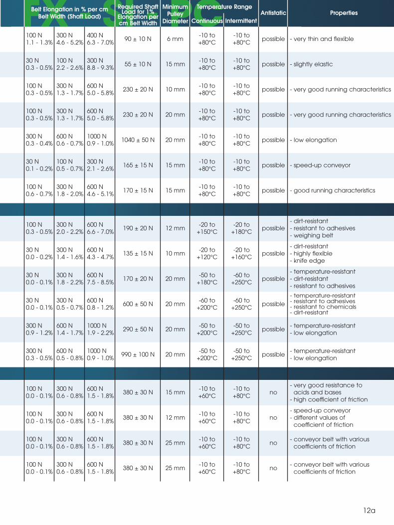
PU FX - SI - PCBelt Elongation in % per cm
Belt Width (Shaft Load)
Required ShaftLoad for 1%
Elongation percm Belt Width
MinimumPulley
Diameter
Temperature Range
Continuous Intermittent
Antistatic Properties
100 N1.1 - 1.3%
300 N4.6 - 5.2%
400 N6.3 - 7.0%
90 ± 10 N 6 mm-10 to+80°C
-10 to+80°C
possible - very thin and flexible
30 N0.3 - 0.5%
100 N2.2 - 2.6%
300 N8.8 - 9.3%
55 ± 10 N 15 mm-10 to+80°C
-10 to+80°C
possible - slightly elastic
100 N0.3 - 0.5%
300 N1.3 - 1.7%
600 N5.0 - 5.8%
230 ± 20 N 10 mm-10 to+80°C
-10 to+80°C
possible - very good running characteristics
100 N0.3 - 0.5%
300 N1.3 - 1.7%
600 N5.0 - 5.8%
230 ± 20 N 20 mm-10 to+80°C
-10 to+80°C
possible - very good running characteristics
300 N0.3 - 0.4%
600 N0.6 - 0.7%
1000 N0.9 - 1.0%
1040 ± 50 N 20 mm-10 to+80°C
-10 to+80°C
possible - low elongation
30 N0.1 - 0.2%
100 N0.5 - 0.7%
300 N2.1 - 2.6%
165 ± 15 N 15 mm-10 to+80°C
-10 to+80°C
possible - speed-up conveyor
100 N0.6 - 0.7%
300 N1.8 - 2.0%
600 N4.6 - 5.1%
170 ± 15 N 15 mm-10 to+80°C
-10 to+80°C
possible - good running characteristics
100 N0.3 - 0.5%
300 N2.0 - 2.2%
600 N6.6 - 7.0%
190 ± 20 N 12 mm-20 to
+150°C-20 to
+180°Cpossible
- dirt-resistant- resistant to adhesives- weighing belt
30 N0.0 - 0.2%
300 N1.4 - 1.6%
600 N4.3 - 4.7%
135 ± 15 N 10 mm-20 to
+120°C-20 to
+160°Cpossible
- dirt-resistant- highly flexible- knife edge
30 N0.0 - 0.1%
300 N1.8 - 2.2%
600 N7.5 - 8.5%
170 ± 20 N 20 mm-50 to
+180°C-60 to
+250°Cpossible
- temperature-resistant- dirt-resistant- resistant to adhesives
30 N0.0 - 0.1%
300 N0.5 - 0.7%
600 N0.8 - 1.2%
600 ± 50 N 20 mm-60 to
+200°C-60 to
+250°Cpossible
- temperature-resistant- resistant to adhesives- resistant to chemicals- dirt-resistant
300 N0.9 - 1.2%
600 N1.4 - 1.7%
1000 N1.9 - 2.2%
290 ± 50 N 20 mm-50 to
+200°C-50 to
+250°Cpossible
- temperature-resistant- low elongation
300 N0.3 - 0.5%
600 N0.5 - 0.8%
1000 N0.9 - 1.0%
990 ± 100 N 20 mm-50 to
+200°C-50 to
+250°Cpossible
- temperature-resistant- low elongation
100 N0.0 - 0.1%
300 N0.6 - 0.8%
600 N1.5 - 1.8%
380 ± 30 N 15 mm-10 to+60°C
-10 to+80°C
no- very good resistance to
acids and bases- high coefficient of friction
100 N0.0 - 0.1%
300 N0.6 - 0.8%
600 N1.5 - 1.8%
380 ± 30 N 12 mm-10 to+60°C
-10 to+80°C
no- speed-up conveyor- different values of
coefficient of friction
100 N0.0 - 0.1%
300 N0.6 - 0.8%
600 N1.5 - 1.8%
380 ± 30 N 25 mm-10 to+60°C
-10 to+80°C
no- conveyor belt with various
coefficients of friction
100 N0.0 - 0.1%
300 N0.6 - 0.8%
600 N1.5 - 1.8%
380 ± 30 N 25 mm-10 to+60°C
-10 to+80°C
no- conveyor belt with various
coefficients of friction
12a
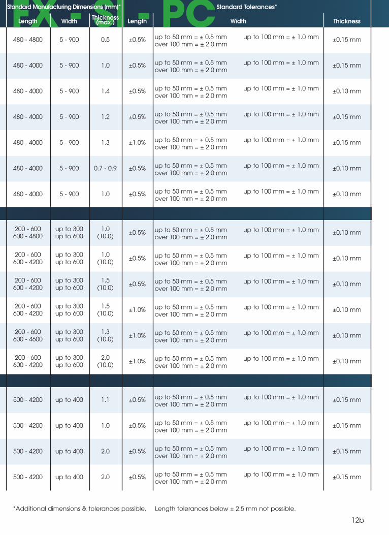
FX - SI - PCPU FX - SI - PC
*Additional dimensions & tolerances possible. Length tolerances below ± 2.5 mm not possible.
istics
istics
480 - 4800 5 - 900 0.5 ±0.5% up to 50 mm = ± 0.5 mmover 100 mm = ± 2.0 mm
up to 100 mm = ± 1.0 mm ±0.15 mm
480 - 4000 5 - 900 1.0 ±0.5% up to 50 mm = ± 0.5 mmover 100 mm = ± 2.0 mm
up to 100 mm = ± 1.0 mm ±0.15 mm
480 - 4000 5 - 900 1.4 ±0.5% up to 50 mm = ± 0.5 mmover 100 mm = ± 2.0 mm
up to 100 mm = ± 1.0 mm ±0.10 mm
480 - 4000 5 - 900 1.2 ±0.5% up to 50 mm = ± 0.5 mmover 100 mm = ± 2.0 mm
up to 100 mm = ± 1.0 mm ±0.15 mm
480 - 4000 5 - 900 1.3 ±1.0% up to 50 mm = ± 0.5 mmover 100 mm = ± 2.0 mm
up to 100 mm = ± 1.0 mm ±0.15 mm
480 - 4000 5 - 900 0.7 - 0.9 ±0.5% up to 50 mm = ± 0.5 mmover 100 mm = ± 2.0 mm
up to 100 mm = ± 1.0 mm ±0.10 mm
480 - 4000 5 - 900 1.0 ±0.5% up to 50 mm = ± 0.5 mmover 100 mm = ± 2.0 mm
up to 100 mm = ± 1.0 mm ±0.10 mm
200 - 600600 - 4800
up to 300up to 600
1.0(10.0)
±0.5% up to 50 mm = ± 0.5 mmover 100 mm = ± 2.0 mm
up to 100 mm = ± 1.0 mm ±0.10 mm
200 - 600600 - 4200
up to 300up to 600
1.0(10.0)
±0.5% up to 50 mm = ± 0.5 mmover 100 mm = ± 2.0 mm
up to 100 mm = ± 1.0 mm ±0.10 mm
200 - 600600 - 4200
up to 300up to 600
1.5(10.0)
±0.5% up to 50 mm = ± 0.5 mmover 100 mm = ± 2.0 mm
up to 100 mm = ± 1.0 mm ±0.10 mm
200 - 600600 - 4200
up to 300up to 600
1.5(10.0)
±1.0% up to 50 mm = ± 0.5 mmover 100 mm = ± 2.0 mm
up to 100 mm = ± 1.0 mm ±0.10 mm
200 - 600600 - 4600
up to 300up to 600
1.3(10.0)
±1.0% up to 50 mm = ± 0.5 mmover 100 mm = ± 2.0 mm
up to 100 mm = ± 1.0 mm ±0.10 mm
200 - 600600 - 4200
up to 300up to 600
2.0(10.0)
±1.0% up to 50 mm = ± 0.5 mmover 100 mm = ± 2.0 mm
up to 100 mm = ± 1.0 mm ±0.10 mm
500 - 4200 up to 400 1.1 ±0.5% up to 50 mm = ± 0.5 mmover 100 mm = ± 2.0 mm
up to 100 mm = ± 1.0 mm ±0.15 mm
500 - 4200 up to 400 1.0 ±0.5% up to 50 mm = ± 0.5 mmover 100 mm = ± 2.0 mm
up to 100 mm = ± 1.0 mm ±0.15 mm
500 - 4200 up to 400 2.0 ±0.5% up to 50 mm = ± 0.5 mmover 100 mm = ± 2.0 mm
up to 100 mm = ± 1.0 mm ±0.15 mm
500 - 4200 up to 400 2.0 ±0.5% up to 50 mm = ± 0.5 mmover 100 mm = ± 2.0 mm
up to 100 mm = ± 1.0 mm ±0.15 mm
Standard Manufacturing Dimensions [mm]* Standard Tolerances*
Length WidthThickness
(max.) WidthLength Thickness
12b
FX - SI - PC
13
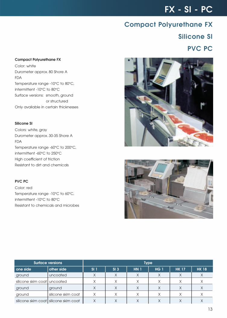
Compact Polyurethane FX
Color: white
Durometer approx. 80 Shore A
FDA
Temperature range -10°C to 80°C,
intermittent -10°C to 80°C
Surface versions: smooth, ground
or structured
Only available in certain thicknesses
Silicone SI
Colors: white, gray
Durometer approx. 30-35 Shore A
FDA
Temperature range -60°C to 200°C,
intermittent -60°C to 250°C
High coefficient of friction
Resistant to dirt and chemicals
PVC PC
Color: red
Temperature range -10°C to 60°C,
intermittent -10°C to 80°C
Resistant to chemicals and microbes
Compact Polyurethane FX
Silicone SI
PVC PC
Surface versions Type
one side other side SI 1 SI 3 HN 1 HG 1 HK 17 HK 18
ground uncoated X X X X X X
silicone skim coat uncoated X X X X X X
ground ground X X X X X X
ground silicone skim coat X X X X X X
silicone skim coat silicone skim coat X X X X X X
Design Considerations
14
ESBAND truly endless woven flat belts offer the opportunity to create limitless belt drive designs.
Below is a helpful guideline regarding pulley designs, belt layout, placement of idlers and special belt drive designs.
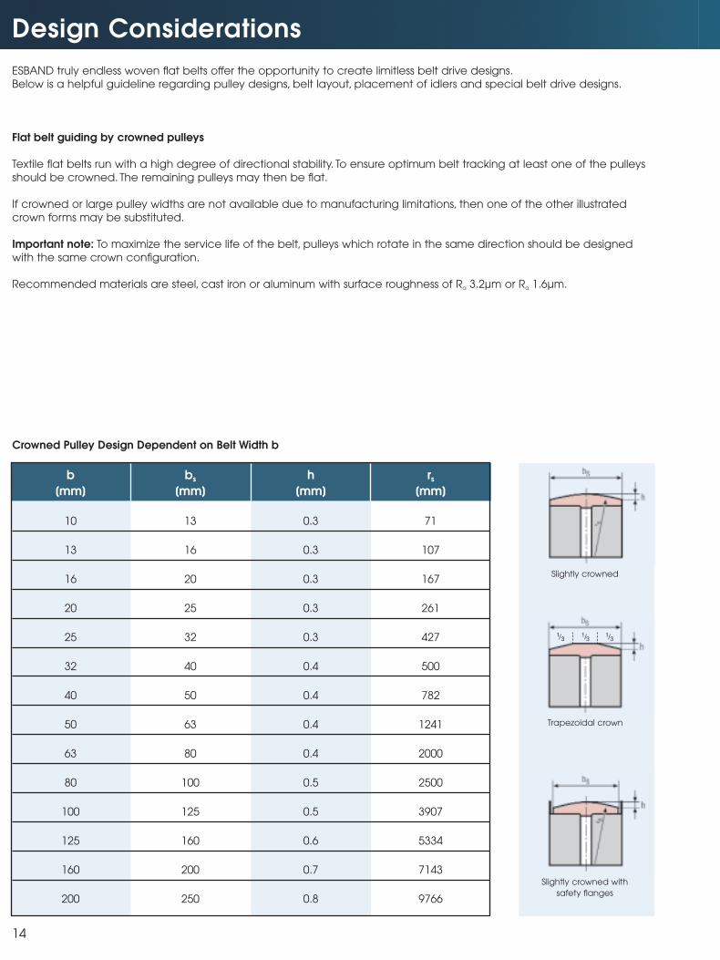
Flat belt guiding by crowned pulleys
Textile flat belts run with a high degree of directional stability. To ensure optimum belt tracking at least one of the pulleys
should be crowned. The remaining pulleys may then be flat.
If crowned or large pulley widths are not available due to manufacturing limitations, then one of the other illustrated
crown forms may be substituted.
Important note: To maximize the service life of the belt, pulleys which rotate in the same direction should be designed
with the same crown configuration.
Recommended materials are steel, cast iron or aluminum with surface roughness of Ra 3.2µm or Ra 1.6µm.
Crowned Pulley Design Dependent on Belt Width b
b bs h rs
[mm] [mm] [mm] [mm]
10 13 0.3 71
13 16 0.3 107
16 20 0.3 167
20 25 0.3 261
25 32 0.3 427
32 40 0.4 500
40 50 0.4 782
50 63 0.4 1241
63 80 0.4 2000
80 100 0.5 2500
100 125 0.5 3907
125 160 0.6 5334
160 200 0.7 7143
200 250 0.8 9766
13
13
13
Slightly crowned
Trapezoidal crown
Slightly crowned with
safety flanges
Drive Layout
15
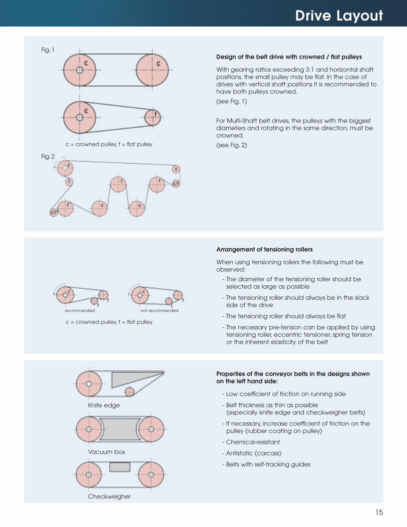
Design of the belt drive with crowned / flat pulleys
With gearing ratios exceeding 3:1 and horizontal shaft
positions, the small pulley may be flat. In the case of
drives with vertical shaft positions it is recommended to
have both pulleys crowned.
(see Fig. 1)
For Multi-Shaft belt drives, the pulleys with the biggest
diameters and rotating in the same direction, must be
crowned.
(see Fig. 2)
Arrangement of tensioning rollers
When using tensioning rollers the following must be
observed:
- The diameter of the tensioning roller should be
selected as large as possible
- The tensioning roller should always be in the slack
side of the drive
- The tensioning roller should always be flat
- The necessary pre-tension can be applied by using
tensioning roller, eccentric tensioner, spring tension
or the inherent elasticity of the belt
Properties of the conveyor belts in the designs shownon the left hand side:
- Low coefficient of friction on running side
- Belt thickness as thin as possible
(especially knife edge and checkweigher belts)
- If necessary, increase coefficient of friction on the
pulley (rubber coating on pulley)
- Chemical-resistant
- Antistatic (carcass)
- Belts with self-tracking guides
Knife edge
Vacuum box
Checkweigher
c = crowned pulley, f = flat pulley
c = crowned pulley, f = flat pulley
not recommendedrecommended
Fig.1
Fig.2
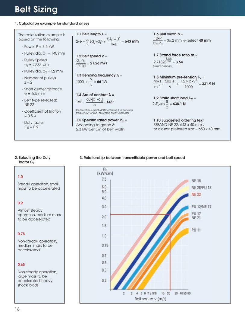
1.6 Belt width b =
1.7 Strand force ratio m =
1.8 Minimum pre-tension FV =
1.9 Static shaft load FW =
1.10 Suggested ordering text:ESBAND NE 22; 643 x 40 mm ,or closest preferred size = 650 x 40 mm
Belt Sizing
16
1. Calculation example for standard drives
The calculation example is
based on the following:
- Power P = 7.5 kW
- Pulley dia. d1 = 140 mm
- Pulley Speed
n1 = 2900 rpm
- Pulley dia. d2 = 52 mm
- Number of pulleys
z = 2
- Shaft center distance
e = 165 mm
- Belt type selected:
NE 22
- Coefficient of friction
= 0.5 µ
- Duty factor
CB = 0.9
1.0
Steady operation, small
mass to be accelerated
0.9
Almost steady
operation, medium mass
to be accelerated
0.75
Non-steady operation,
medium mass to be
accelerated
0.65
Non-steady operation,
large mass to be
accelerated, heavy
shock loads
2. Selecting the Duty factor CB
3. Relationship between transmittable power and belt speed
Belt speed v [m/s]
2•e + (d2+d
1) + = 643 mm
π2
(d2-d
1)2
4•e= 36.2 mm => select 40 mm
10•P
CB•PN
(Euler's number)
• + = 331.9 Nm+1
m-1
500•P
v
1.21•b•v2
1000
2•Fv•sin = 638.1 Nß
2
2.71828 = 3.64
ß•π•µ
180
180 - = 148°60•ld1
-d2l
e
= 21.26 m/sd
1•n
1
19100
1.1 Belt length L =
1.2 Belt speed v =
1.3 Bending frequency fB =
1.4 Arc of contact ß =
Please check graph 4 "Determining the bending frequency" for min. allowable pulley diameter
1.5 Specific rated power PN =
According to graph 3:2.3 kW per cm of belt width
1000 •z• = 66 1/sv
L
Belt Sizing
17
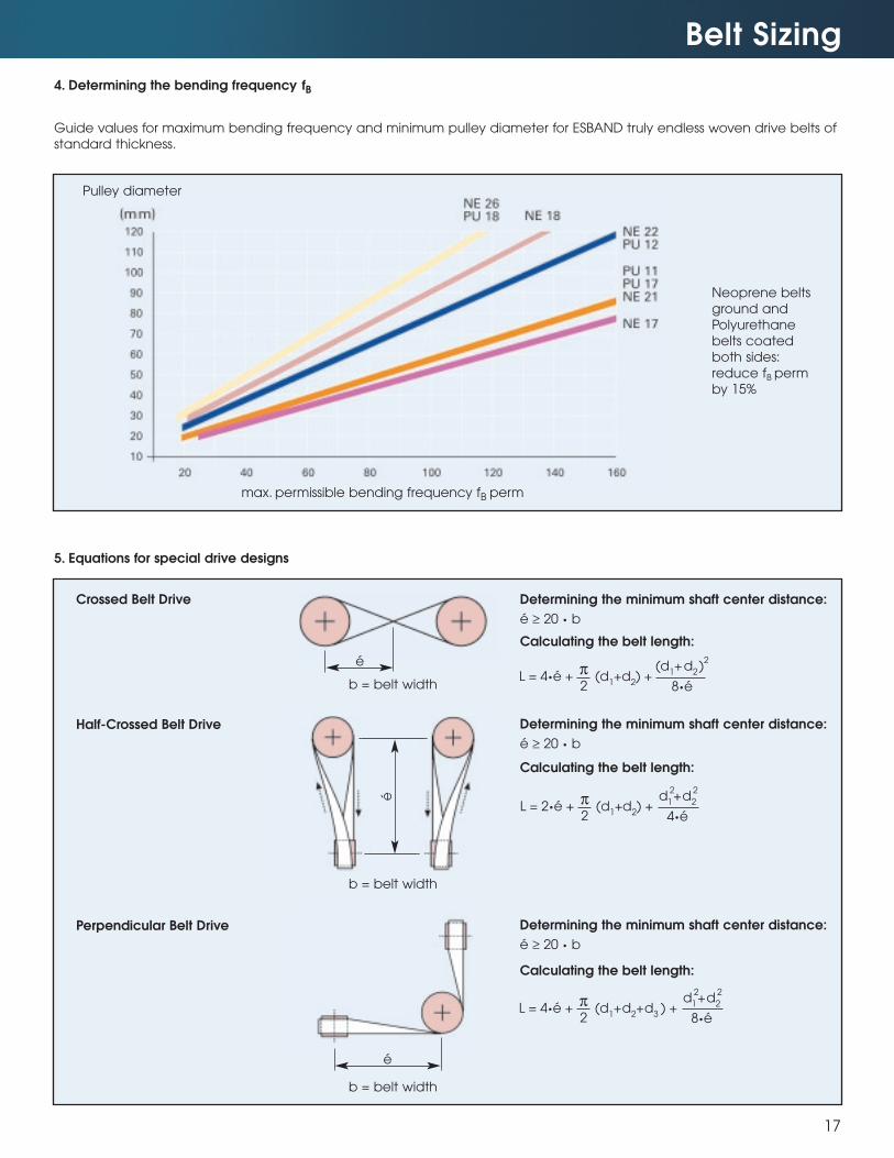
4. Determining the bending frequency
Guide values for maximum bending frequency and minimum pulley diameter for ESBAND truly endless woven drive belts of
standard thickness.
Neoprene belts
ground and
Polyurethane
belts coated
both sides:
reduce fB perm
by 15%
Pulley diameter
max. permissible bending frequency fB perm
5. Equations for special drive designs
Perpendicular Belt Drive
Half-Crossed Belt Drive
Crossed Belt Drive Determining the minimum shaft center distance:
é ≥ 20 • b
Calculating the belt length:
Determining the minimum shaft center distance:
é ≥ 20 • b
Calculating the belt length:
Determining the minimum shaft center distance:
é ≥ 20 • b
Calculating the belt length:
b = belt width
b = belt width
L = 4•é + (d1+d
2) +
π
2
(d1+d
2)2
8•é
L = 2•é + (d1+d
2) +
π
2
d1+d
2
4•é
22
L = 4•é + (d1+d
2+d
3) +
π
2
d1+d
2
8•é
22
fB
b = belt width
é
é
é
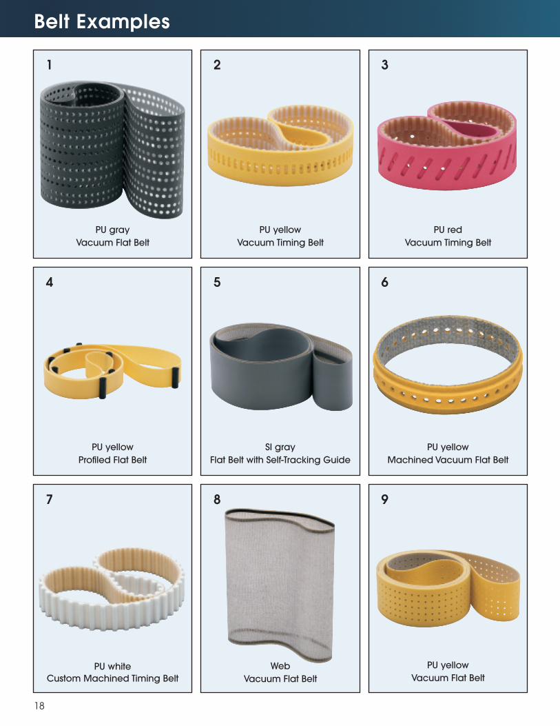
Belt Examples
18
1
4
2
5
3
6
PU gray
Vacuum Flat Belt
PU yellow
Vacuum Timing Belt
PU red
Vacuum Timing Belt
PU yellow
Profiled Flat Belt
SI gray
Flat Belt with Self-Tracking Guide
PU yellow
Machined Vacuum Flat Belt
7 8 9
PU white
Custom Machined Timing Belt
Web
Vacuum Flat Belt
PU yellow
Vacuum Flat Belt
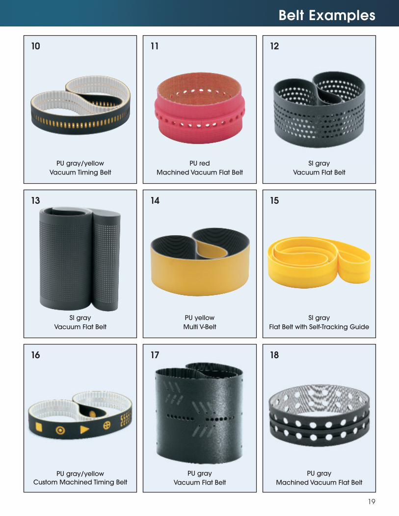
Belt Examples
19
10
PU gray/yellow
Vacuum Timing Belt
11
PU red
Machined Vacuum Flat Belt
12
SI gray
Vacuum Flat Belt
13
SI gray
Vacuum Flat Belt
14
PU yellow
Multi V-Belt
15
SI gray
Flat Belt with Self-Tracking Guide
16
PU gray/yellow
Custom Machined Timing Belt
17
PU gray
Vacuum Flat Belt
18
PU gray
Machined Vacuum Flat Belt
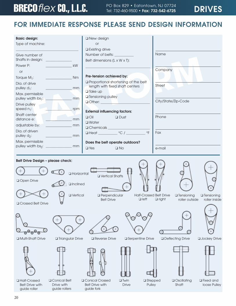
FAX FORM
20
FOR IMMEDIATE RESPONSE PLEASE SEND DESIGN INFORMATION
Basic design:Type of machine:
____________________________________
Give number ofShafts in design: _______________
Power P: _______________ kW
or
Torque M1: _______________ Nm
Dia. of drivepulley d1: _______________ mm
Max. permissiblepulley width bs1: _______________ mm
Drive pulleyspeed n1: _______________ rpm
Shaft center distance e: _______________ mm
adjustable by: _______________ mm
Dia. of drivenpulley d2: _______________ mm
Max. permissiblepulley width bs2: _______________ mm
❑ New design
or
❑ Existing drive
Number of belts:
Belt dimensions (L x W x T):
Pre-tension achieved by:
❑ Proportional shortening of the beltlength with fixed shaft centers
❑ Take up
❑ Tensioning pulley
❑ Other:
External influencing factors:
❑ Oil ❑ Dust
❑ Water
❑ Chemicals
❑ Heat °C / °F
Does the belt operate outdoors?
❑ Yes ❑ No
Name
Company
Street
City/State/Zip-Code
Phone
Fax
Belt Drive Design – please check:
❑ Open Drive
❑ Horizontal
❑ Inclined
❑ Vertical
❑ Vertical Shafts
❑ PerpendicularBelt Drive
❑ Tensioningroller outside
❑ Tensioningroller inside
Half-Crossed Belt Drive❑ left ❑ right
❑ Crossed Belt Drive
❑ Multi-Shaft Drive ❑ Triangular Drive ❑ Reverse Drive ❑ Serpentine Drive ❑ Deflecting Drive ❑ Jockey Drive
❑ Half-CrossedBelt Drive withguide roller
❑ Conical BeltDrive withguide rollers
❑ TwinDrive
❑ SteppedPulley
❑ OscillatingShaft
❑ Fixed andloose Pulley
❑ Conical CrossedBelt Drive withguide fork
DRIVESPO Box 829 • Eatontown, NJ 07724Tel: 732-460-9500 • Fax: 732-542-6725
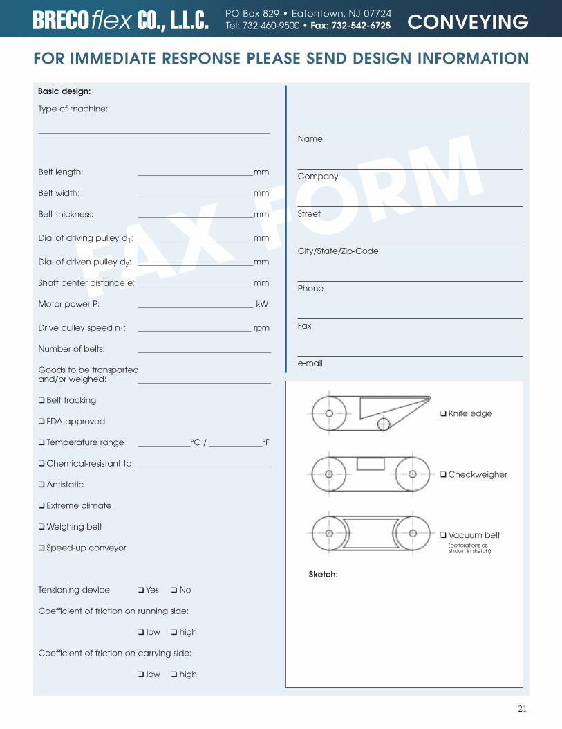
FAX FORM
Sketch:
❑ Knife edge
❑ Checkweigher
❑ Vacuum belt(perforations as shown in sketch)
21
CONVEYINGPO Box 829 • Eatontown, NJ 07724Tel: 732-460-9500 • Fax: 732-542-6725
Type of machine:
Belt length: mm
Belt width: mm
Belt thickness: mm
Dia. of driving pulley d1: mm
Dia. of driven pulley d2: mm
Shaft center distance e: mm
Motor power P: kW
Drive pulley speed n1: rpm
Number of belts:
Goods to be transportedand/or weighed:
❑ Belt tracking
❑ FDA approved
❑ Temperature range °C / °F
❑ Chemical-resistant to
❑ Antistatic
❑ Extreme climate
❑ Weighing belt
❑ Speed-up conveyor
Tensioning device ❑ Yes ❑ No
Coefficient of friction on running side:
❑ low ❑ high
Coefficient of friction on carrying side:
❑ low ❑ high
Name
Company
Street
City/State/Zip-Code
Phone
Fax
Basic design:
FOR IMMEDIATE RESPONSE PLEASE SEND DESIGN INFORMATION
F
BRECOflex Product Catalogs I S O 9 0 0 1CERTIFIEDCOMPANY
222 Industrial Way WestlEatontownlNJ 07724Tel: 732-460-9500lFax: 732-542-6725
www.brecoflex.comemail: [email protected]
Copyright 2003 BRECOflex CO., L.L.C. • BRECO®, BRECOFLEX® & ATN® are registered trademarks of BRECO Antriebstechnik GmbH • ARC-POWER® is a registered trademark of BRECOflex CO., L.L.C. • Kevlar® is a registered
trademark of DuPont Patents Pending • ESBAND® is a registered trademark of Max Schlatterer GmbH & Co. KG Patents Pending. Specifications are subject to change without prior notice.
All recommendations for the use of the products described herein and all other data or information set forth in this publication, whether concerning such products or otherwise, are furnished without any guarantee, warranty representations or inducement of any kind whether expressed or implied, including but not limited to warranties of merchantability and fitness for a particular purpose. BRECOflex CO., L.L.C. expressly disclaims liability under any theory, including without limitation, contract negligence, misrepresentation or breach of any obligation relating to the recommendation, data or information set forth herein. Readers and customers are encouraged to conduct their own test before using any product. Read its label and all related instructions. BRECOflex CO., L.L.C. reserves the right to make changes in the technical and dimensional specifications of its products without prior notice. Responsibility for expenses incurred as a result of product changes or discontinuance of a product lies solely with the purchaser.
Calculations Driving, Positioning, Conveying
Power, Torque, and Peripheral Force calculations.
Catalog #B204
Polyurethane Timing Belts with Weld-on Profiles
Dividing, Stepping, Positioning.
Catalog #B203
Accessory Items for Polyurethane Timing Belts
Pulleys, Tensioners, Clamps, Tensioning Clamps.
Catalog #B205
Tension Meter
Improve Performance, lifetime, positioning accuracy, bearing load, and noise level.
Catalog #B207
ESBAND Truly Endless Woven Flat Belts
Catalog #B210
Wide variety of Polyurethane, Neoprene and Silicone state-of-the-art flat belts.
ARC-POWER Technology
Catalog #B217
ARC-POWER Technology Best Performing Timing Belts Available.
Timing Belts Backings
Polyurethane Timing Belts in Metric and English pitches with a wide range of cover materials.
Catalog #B208
Pulleys for Polyurethane and Neoprene Timing Belts
Catalog #B216
Finished pulleys and stock pulley program.
Polyurethane Timing Belts
Catalog #B212
Industry leading polyurethane timing belts In Metric and English pitches. Widest range of available options.
ATN® - Convertible Timing Belt System
ATN technology allows the reconfiguration of profiled timing belts at the customer site.
Catalog #B209
Prin
ted
10/2
015
Final BC.indd 1 10/15/15 1:38 PM