Embed Size (px)
Citation preview

0740 800 220 20130308
ESAB - ABB
Robot integrationInterface W82 Integrated and W82 Anybus
Integration manual

- 2 -TOCe
Rights reserved to alter specifications without notice.
READ THIS FIRST 3. . . . . . . . . . . . . . . . . . . . . . . . . . . . . . . . . . . . . . . . . . . . . . . . . . . . . . . . . . . . . . . . .
HOW TO USE THIS MANUAL 3. . . . . . . . . . . . . . . . . . . . . . . . . . . . . . . . . . . . . . . . . . . . . . . . . . . . . . .
DOCUMENTATION OVERVIEW 3. . . . . . . . . . . . . . . . . . . . . . . . . . . . . . . . . . . . . . . . . . . . . . . . . . . . .
INTRODUCTION 4. . . . . . . . . . . . . . . . . . . . . . . . . . . . . . . . . . . . . . . . . . . . . . . . . . . . . . . . . . . . . . . . . . .
Supported equipment 4. . . . . . . . . . . . . . . . . . . . . . . . . . . . . . . . . . . . . . . . . . . . . . . . . . . . . . . . . . .
Schematic system design 5. . . . . . . . . . . . . . . . . . . . . . . . . . . . . . . . . . . . . . . . . . . . . . . . . . . . . . . .
W82 INTEGRATED VERSION 6. . . . . . . . . . . . . . . . . . . . . . . . . . . . . . . . . . . . . . . . . . . . . . . . . . . . . . .
DeviceNet (Integrated version) 6. . . . . . . . . . . . . . . . . . . . . . . . . . . . . . . . . . . . . . . . . . . . . . . . . . .
Network connection 6. . . . . . . . . . . . . . . . . . . . . . . . . . . . . . . . . . . . . . . . . . . . . . . . . . . . . . . . . . . . .
DeviceNet network (Integrated version) 7. . . . . . . . . . . . . . . . . . . . . . . . . . . . . . . . . . . . . . . . . . .
Termination 7. . . . . . . . . . . . . . . . . . . . . . . . . . . . . . . . . . . . . . . . . . . . . . . . . . . . . . . . . . . . . . . . . . . . .
Location of SW1 and SW2 on the welding data board, 24AP1 8. . . . . . . . . . . . . . . . . . . . . . .
W82 ANYBUS 9. . . . . . . . . . . . . . . . . . . . . . . . . . . . . . . . . . . . . . . . . . . . . . . . . . . . . . . . . . . . . . . . . . . . .
Fieldbus connection 9. . . . . . . . . . . . . . . . . . . . . . . . . . . . . . . . . . . . . . . . . . . . . . . . . . . . . . . . . . . .
W82 DeviceNet 10. . . . . . . . . . . . . . . . . . . . . . . . . . . . . . . . . . . . . . . . . . . . . . . . . . . . . . . . . . . . . . . . . .
DeviceNet network 10. . . . . . . . . . . . . . . . . . . . . . . . . . . . . . . . . . . . . . . . . . . . . . . . . . . . . . . . . . . . . .
Tap for DeviceNet at Weld Data Unit 11. . . . . . . . . . . . . . . . . . . . . . . . . . . . . . . . . . . . . . . . . . . . . .
Termination 11. . . . . . . . . . . . . . . . . . . . . . . . . . . . . . . . . . . . . . . . . . . . . . . . . . . . . . . . . . . . . . . . . . . . .
Position of SW1 on the welding data board, 24AP1. 12. . . . . . . . . . . . . . . . . . . . . . . . . . . . . . .
24AP4 Fieldbus board - DeviceNet 13. . . . . . . . . . . . . . . . . . . . . . . . . . . . . . . . . . . . . . . . . . . . . . . .
Fieldbus connector 13. . . . . . . . . . . . . . . . . . . . . . . . . . . . . . . . . . . . . . . . . . . . . . . . . . . . . . . . . . . . . .
Configuration 14. . . . . . . . . . . . . . . . . . . . . . . . . . . . . . . . . . . . . . . . . . . . . . . . . . . . . . . . . . . . . . . . . . .
Baud rate 14. . . . . . . . . . . . . . . . . . . . . . . . . . . . . . . . . . . . . . . . . . . . . . . . . . . . . . . . . . . . . . . . . . . . . . .
Node address (Mac ID) 14. . . . . . . . . . . . . . . . . . . . . . . . . . . . . . . . . . . . . . . . . . . . . . . . . . . . . . . . . . .
LED indicators 15. . . . . . . . . . . . . . . . . . . . . . . . . . . . . . . . . . . . . . . . . . . . . . . . . . . . . . . . . . . . . . . . . .
INSTALLATION OF HARDWARE 16. . . . . . . . . . . . . . . . . . . . . . . . . . . . . . . . . . . . . . . . . . . . . . . . . . . .
Regarding U82 16. . . . . . . . . . . . . . . . . . . . . . . . . . . . . . . . . . . . . . . . . . . . . . . . . . . . . . . . . . . . . . . . . .
Installing W82 16. . . . . . . . . . . . . . . . . . . . . . . . . . . . . . . . . . . . . . . . . . . . . . . . . . . . . . . . . . . . . . . . . . .
CONFIGURATION EXAMPLE 20. . . . . . . . . . . . . . . . . . . . . . . . . . . . . . . . . . . . . . . . . . . . . . . . . . . . . . .
IO configuration 20. . . . . . . . . . . . . . . . . . . . . . . . . . . . . . . . . . . . . . . . . . . . . . . . . . . . . . . . . . . . . . . .
Signals out 21. . . . . . . . . . . . . . . . . . . . . . . . . . . . . . . . . . . . . . . . . . . . . . . . . . . . . . . . . . . . . . . . . . . . .
Signals in 22. . . . . . . . . . . . . . . . . . . . . . . . . . . . . . . . . . . . . . . . . . . . . . . . . . . . . . . . . . . . . . . . . . . . . . .
Process definitions 24. . . . . . . . . . . . . . . . . . . . . . . . . . . . . . . . . . . . . . . . . . . . . . . . . . . . . . . . . . . . . .
Cross reference Integrated 29. . . . . . . . . . . . . . . . . . . . . . . . . . . . . . . . . . . . . . . . . . . . . . . . . . . . . . .
Cross reference Anybus 31. . . . . . . . . . . . . . . . . . . . . . . . . . . . . . . . . . . . . . . . . . . . . . . . . . . . . . . . .
SERVICE INSTRUCTIONS 33. . . . . . . . . . . . . . . . . . . . . . . . . . . . . . . . . . . . . . . . . . . . . . . . . . . . . . . . . .
What is ESD? 33. . . . . . . . . . . . . . . . . . . . . . . . . . . . . . . . . . . . . . . . . . . . . . . . . . . . . . . . . . . . . . . . . . .
SPARE PARTS 33. . . . . . . . . . . . . . . . . . . . . . . . . . . . . . . . . . . . . . . . . . . . . . . . . . . . . . . . . . . . . . . . . . . .
Ordering spare parts 33. . . . . . . . . . . . . . . . . . . . . . . . . . . . . . . . . . . . . . . . . . . . . . . . . . . . . . . . . . . .

S0740 800 220/E20130308/P34© ESAB AB 2013
- 3 -cr09_00
READ THIS FIRST
Installation must be performed by an experienced person, and electrical work only bya trained electrician. Use only recommended replacement parts.
This integration manual is intended for use by technicians with electrical/electronictraining for help in connection with installation and integration of robotic equipmentwith ESAB products.
Use the spare parts list as a guide to where the components are located in theequipment. The spare parts list is published as a separate document, see page 33.
This manual contains details of design changes that have been made up to andincluding March 2013.
HOW TO USE THIS MANUAL
This manual describes two different interfaces, W82 Integrated and W82 Anybus.Only read and use the information applicable for your chosen interface.
DOCUMENTATION OVERVIEW
The documentation structure. This manual is the ESAB - ABB integration manual.
Delivered in the box with the unit
Delivered with the
ABB robot
Delivered in the box with
the wire feeder mounting kit
Delivered with the ESAB
robot package
Power source
Instruction manual
W 82
Instruction manual
RoboFeed / FeedControl
Instruction manual
RoboFeed / FeedControl
Assembly instruction
ESAB – ABB
Integration manualABB – robot
Product manual“This manual”

S0740 800 220/E20130308/P34© ESAB AB 2013
- 4 -cr09_00
INTRODUCTION
This manual is intended to guide a system integrator, when integrating ESABequipment with an ABB robotic solution.
Supported equipment
Power source
Power sources for Integrated system: Mig 5000i / Mig5000iw
Power sources for Anybus system: Mig 5000i / 5000iw, Mig 4004i Pulse, Mig 4002c /4002cw, Mig 5002c / 5002cw, Mig 6502c / 6502cw
Wire feed system
For hollow wrist robots like IRB1520ID, 1600ID and 2600ID it is recommended to usedrive unit RoboFeed 3004HW and electronic unit Feed Control Box 3004HW.
For robots with traditional upper arms it is recommended to use wire feed systemRoboFeed 3004W. RoboFeed 3004W contains both a mechanical drive unit andelectronics.
Interface unit
W82
The interface unit is installed between a welding equipment and an automationequipment, such as robots. The W82 is available in several versions. This manualdescribes the following versions:
� W82 Integrated
� W82 Anybus
CAUTION
Read and understand the instruction manual beforeinstalling or operating.
CAUTIONSTATIC ELECTRICITY can damage circuitboards and electronic components.
� Observe precautions for handling electrostatic-sensitive devices.
� Use proper static-proof bags and boxes.ESD
S0740 800 220/E20130308/P34© ESAB AB 2013
- 5 -cr09_00
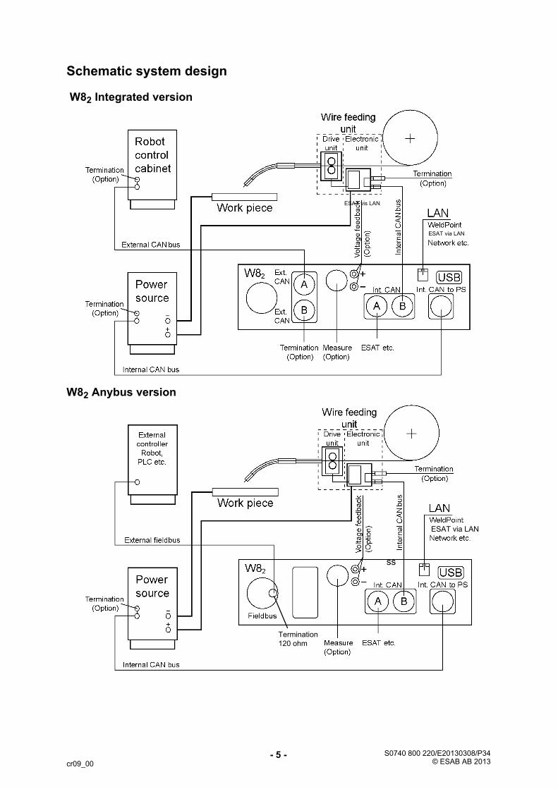
Schematic system design
W82 Integrated version
ESAT vis LAN
ESAT via LAN
W82 Anybus version
ESAT via LAN
Termination
120 ohm
ss

S0740 800 220/E20130308/P34© ESAB AB 2013
- 6 -cr09_01
W82 INTEGRATED VERSION
External CAN bus interface integrated in welding data board 24AP1. DeviceNetcommunication is used.
Internal CAN to Power SourceExternal CAN bus connection to robot
W82 integrated version
DeviceNet (Integrated version)
DeviceNet is used to control valves, sensors, I/O units and automation equipment inindustrial automation. DeviceNet communication link is based on a broadcast-oriented, communication protocol, the Controller Area Network (CAN).
This protocol has I/O response and high reliability even for demanding applications,for example control of brakes.
Network connection
To secure a reliable communication on the bus, the “drop lines” are restricted in theDeviceNet standard to maximum length of 6 meters (20 ft.). Note that a correcttermination of the bus is also essential for a reliable communication.

S0740 800 220/E20130308/P34© ESAB AB 2013
- 7 -cr09_01
DeviceNet network (Integrated version)
W82 Integrated version in the network
Termination
DeviceNet uses the CAN bus with terminating resistors at each end of the bus. The value of the terminating resistor should be 120 ohm. This should be connectedbetween CAN_H and CAN_L on the bus. Midpoint is connected to 0V for the internalCAN bus (0V_CAN_ext for the external CAN bus) via a 47nF capacitor.
Terminating resistors are included in the W82. They can be connected/disconnectedby the switches, SW1 and SW2. Both the external CAN bus and the internal CANbus have terminating resistors mounted.
Note! When external termination of the buses are used, the termination switchesshall be set in OFF position (disabled).

S0740 800 220/E20130308/P34© ESAB AB 2013
- 8 -cr09_01
Location of SW1 and SW2 on the welding data board, 24AP1
SW1
SW2

S0740 800 220/E20130308/P34© ESAB AB 2013
- 9 -cr09_01_1
W82 ANYBUS
External fieldbus connection via DeviceNet, CANopen or Profibus DP.
W82 fieldbus version
Fieldbus connection
External fieldbus connection to W82

- 10 -cr09_01_2
W82 DeviceNet
DeviceNet is used to control valves, sensors, I/O units and automation equipment inindustrial automation. The DeviceNet communication link is based on abroadcast-oriented, communication protocol, the Controller Area Network (CAN).
This protocol has I/O response and a high reliability even for demandingapplications, for example control of brakes.
Network connection
To secure a reliable communication on the bus, the “drop lines” are restricted in theDeviceNet standard to a maximum length of 6 metres (20 ft).
Note! Correct termination of the bus is essential for a reliable communication.
DeviceNet network
W82 in DeviceNet network

- 11 -cr09_01_2
Tap for DeviceNet at Weld Data Unit
Termination
DeviceNet uses the CAN bus with terminating resistors at each end of the bus. Theterminating resistor should be 120 ohm. This should be connected between CAN_Hand CAN_L on the bus. Midpoint is connected to 0V for the internal CAN bus(0V_CAN_ext for the external CAN bus) via 47nF capacitors.
Terminating resistors are included in the W82. They can be connected/disconnectedby switch SW1. Only the internal CAN bus has terminating resistors mounted.
Note! When the W82 is is located as the last node in the internal bus network, usetermination on the CAN bus:
� Set termination switch SW1 to position “ON”. The CAN bus will be terminatedwith 120 ohm at 24AP1.
� With external termination, set termination switch SW1 to position “OFF”.

- 12 -cr09_01_2
Position of SW1 on the welding data board, 24AP1.
SW1
- 13 -cr09_01_2
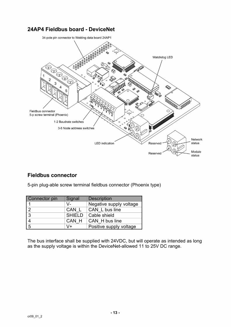
24AP4 Fieldbus board - DeviceNet
Fieldbus connector
5-pin plug-able screw terminal fieldbus connector (Phoenix type)
Connector pin Signal Description
1 V- Negative supply voltage
2 CAN_L CAN_L bus line
3 SHIELD Cable shield
4 CAN_H CAN_H bus line
5 V+ Positive supply voltage
The bus interface shall be supplied with 24VDC, but will operate as intended as longas the supply voltage is within the DeviceNet-allowed 11 to 25V DC range.

- 14 -cr09_01_2
Configuration
A connection to the node is set up towards the assembly object with a busconfiguration tool or directly from a master.
Node address (Mac ID) and baud rate are configured with dip-switches (see pictureof fieldbus board). The range for node address is between 0-63 and baud rate isbetween 0 and 2 (0 = 125 kbit/s, 1 = 250 kbit/s and 2 = 500 kbit/s).
When a DIP-switch is in ”ON” or ”Closed” position, the node interprets it as a logic ”1”.
Baud rate
There are three different baud rates for DeviceNet:
� 125 kbit/s
� 250 kbit/s
� 500 kbit/s.
DIP-switches 1 and 2 are used for baud rate setting.
Baud rate, bits/s Sw 1 Sw 2
125k OFF OFF
250k OFF ON
500k ON OFF
Reserved ON ON
Node address (Mac ID)
Switches 3 to 8 are used to set the node address (0-63). Switch 3 is the MSB, andswitch 8 is LSB.
Address Sw 3 Sw 4 Sw 5 Sw 6 Sw 7 Sw 8
0 OFF OFF OFF OFF OFF OFF
1 OFF OFF OFF OFF OFF ON
2 OFF OFF OFF OFF ON OFF
3 OFF OFF OFF OFF ON ON
62 ON ON ON ON ON OFF
63 ON ON ON ON ON ON

- 15 -cr09_01_2
LED indicators
The fieldbus board is equipped with four bi-colour LED's at the front of the boardshowing the status.
LED 1 and 4 are reserved for future use.
LED 2 - Network status
Colour Frequency Description
Off - Not powered / Not on line
Green Steady on Link OK, On line, Connected
Green Flashing On line, Not connected
Red Steady on Critical link failure
Red Flashing Connection timeout
LED 3 - Module status
Colour Frequency Description
Off - No power to device
Green Steady on Device operational
Green Flashing Data size bigger than configured
Red Steady on Unrecoverable fault
Red Flashing Minor fault
Watchdog LED
The fieldbus board includes a bi-colour watchdog LED, indicating the status of themodule.
Colour Frequency Indication
Red - Unspecified internal error, or running in bootloader mode
Red 1 Hz RAM failure
Red 2 Hz ASIC or FLASH failure
Red 4 Hz DPRAM failure
Green 1 Hz Module initialised and running OK
Green 2 Hz Module not initialised

- 16 -cr09_02
INSTALLATION OF HARDWARE
The installation chapter will describe how to connect the different components. TheESAB integrated software in the robot controller should be installed by ABB beforedelivery to the site.
Regarding U82
The U82 is not supported together with the W82 integrated version. The ABB TeachPendant is used for communicating with the power source.
Installing W82
Connections and control devices
W82 Integrated W82 Anybus
1. Indicating lampOrange indicating lamp - Overheating
2. FieldbusConnection for communication with robot system
3. MeasureConnection for measurement cable for arc voltage feedback and emergencystop signal, measurement kit
4. Internal CANConnections for communication with ESAB wire feed unit and control panel
5. LANConnection to network, Ethernet
6. CAN to welding power sourceConnection for communication with welding power source
7. USBUSB memory connection

- 17 -cr09_02
Mounting W82 on Mig 5000i
� On the power source, remove the two screws that holds the rear handle.
� Remove handle.
� Place the interface box onto the welding power source.
� Place handle on top of the interface box.
� Fasten interface box and handle with the two screws.
Mounting W82 on Mig 4002c, Mig 5002c and Mig 6502c
� On the power source, use the “keyholes” that is normally used for the chainholding the gas tube.
� Place the interface box onto the welding power source.
� Fasten interface box with the two screws.
Installing the wire feeder and control unit
Mount the feeder unit and controller according to the mounting instruction thatcomes in the same box as the units.
Power source
Unpack and install the power source according to the user manual.
Installing the welding gun
Unpack and install the welding gun according to the user manual.
Installing the bobbin holder
Unpack and install the bobbin holder according to the user manual, refer to theassembly instruction for Robot Bobbin Kit “RoboFeed 3004HW”.

- 18 -cr09_02
Installing the cables (W82 Integrated)
ABBTeach pendant
RoboFeed
Mig 5000i/iw
1 Connection between welding W82 and power source. External CAN to power source.
2 Connection between W82 and robot control cabinet. External fieldbus CAN to robot control cabinet.
3 Connection between welding power source and wire feed unit. Internal CAN.
4 Connection between ABB teach pendant, single point of programming, and robot control cabinet.
Note! When using a wire feed unit other than RoboFeed, install a separate arc voltage feedback tothe measurement contact on the control unit.
Installing the cables (W82 Anybus)
RoboFeed
Mig 5000i/iw
1 Connection between welding W82 and power source. External CAN to power source.
2 Connection between W82 and robot control cabinet. External fieldbus CAN to robot control cabinet.
3 Connection between welding power source and wire feed unit. Internal CAN.
4 Connection between welding power source and control panel. Internal CAN.
Note! When using a wire feed unit other than RoboFeed, install a separate arc voltage feedback tothe measurement contact on the control unit.

- 19 -cr09_02
Installing the cables (W82 Anybus) continued
Mig 4004i Pulse
RoboFeed
13
2
4
1 Connection between welding W82 and power source. External CAN to power source.
2 Connection between W82 and robot control cabinet. External fieldbus CAN to robot control cabinet.
3 Connection between welding power source and wire feed unit. Internal CAN:
4 Connection between welding power source and control panel. Internal CAN.
Note! When using a wire feed unit other than RoboFeed, install a separate arc voltage feedback tothe measurement contact on the control unit.
Mig 4002 c/cwMig 5002 c/cwMig 6502 c/cw
RoboFeed
1
3
2
4
1 Connection between welding W82 and power source. External CAN to power source.
2 Connection between W82 and robot control cabinet. External fieldbus CAN to robot control cabinet.
3 Connection between welding power source and wire feed unit. Internal CAN.
4 Connection between welding power source and control panel. Internal CAN.
Note! When using a wire feed unit other than RoboFeed, install a separate arc voltage feedback tothe measurement contact on the control unit.
- 20 -cr09_02
CONFIGURATION EXAMPLE
This section describes examples of IO configurations, process definitions and crossreferences and is ment to be used for reference and as examples.
IO configuration
Unit type
Name = ESAB_W82_Integrated
Name = ESAB_W82_Anybus
Unit
Name = ESAB_W82
IO
Name = typeXxxxYyyy
Description of signal naming convention (if more than 1 robot a prefix is added explaining which robot the signal belongs to).
Type:
� di = Digital input
� do = Digital output
� gi = group input
� go = group output
� ai = analog input
� ao = analog output
Xxxx:
� Signal description
Yyyy:
� Signal action
SignalLabel = <Description>
Category = “ArcWelding”

- 21 -cr09_02
Signals out
This table lists examples of signals from robot to W82
ABB ESAB Description
doWeld doWeldOn Start/Stop welding equipment
doQuickStop doQuickStop Quick stop of welding equipmentwithout end data
doEmStop doEmergencyStop Emergency stop
doFeed doWireFeedOn Start/Stop wire feeding
doGas doGasPurgeOn Start/Stop Gas flow
doAir doAirCleanOn Start/Stop compressed Air flow
doFeedBwd doWireFeedReverseOn Start/Stop reversing wire feed
doRemoteActiveOn Remote active Enabled/Disabled
goWireFeeder doWireFeeder1On Enable/Disable wire feeder 1
doWireFeeder2On Enable/Disable wire feeder 2
doWireFeeder3On Enable/Disable wire feeder 3
doWireFeeder4On Enable/Disable wire feeder 4
doAnalogOn Wirefeed & Voltage referencecontrolled from FP instead of welddata number.
Rel_Wire doReleaseWireOn Execute a current pulse to burn ofthe wire if frozen in weld pole.
doTouchSenseActive doTouchSenseOn Turns on the possibility to searchusing wire or gas cup. Used withsearch instr
goSchedule goWeldDataNumber Recalls a complete set of welddata
aoMigVoltRef aoWeldVoltageRef Value of Voltage reference. Onlyused if AnalogOn is enabled.
aoMigWfRef aoWireFeedSpeedRef Value of Wire feed speed reference. Only used if AnalogOn is enabled.

- 22 -cr09_02
Signals in
This table lists examples of signals from W82 to robot
ABB ESAB Description
diWeldEst diWeldingActive This signal indicates that the welding equipment I occupied withwelding
diArcEst diArcEstablished This signal will be activated whenthe arc is established at a weldstart.
diTouchSenseContact diTouchSenseResponse This signal indicates contact withwire or gas cup if TouchSenseOnis enabled.
diRemoteActive diRemoteActive Indicates that remote active is on.
diWF1Selected diWireFeeder1Active Wire feeder 1 active.
diWF2Selected diWireFeeder2Active Wire feeder 2 active.
diWF3Selected diWireFeeder3Active Wire feeder 3 active.
diWF4Selected diWireFeeder4Active Wire feeder 4 active.
diError1 diErrorType1 See U82 manual for future information regarding the error bit mask
diError2 diErrorType2 See U82 manual for future information regarding the error bit mask
diError3 diErrorType3 See U82 manual for future information regarding the error bit mask
diError4 diErrorType4 See U82 manual for future information regarding the error bit mask
diError5 diErrorType5 See U82 manual for future information regarding the error bit mask
diError6 diErrorType6 See U82 manual for future information regarding the error bit mask
diError7 diErrorType7 See U82 manual for future information regarding the error bit mask
diError8 diErrorType8 See U82 manual for future information regarding the error bit mask
diWduError diWDUErrorActive If active there is an error in theWeld Data Unit.
diPsError diPSErrorActive If active there is an error in thePower Source
diWfError diWFErrorActive If active there is an error in theactive Wire Feeder.
diGasActive diGasActive Indicates that gas is flowing thrugasflow sensor.
diCollisionDetect diCollisionDetected Indicates robot collision.
diSynergyActive Indicates that synergy is active.
diWireFeedActive Indicates that Wire Feeder is active.
aiVoltage aiMeasuredVoltage This is the measured voltage fromthe welding equipment.

- 23 -cr09_02
ABB DescriptionESAB
aiCurrent aiMeasuredCurrent This is the measured current fromthe welding equipment.
aiPower aiMeasuredPower This is the measured power fromthe welding equipment.
giWeldDataNumber This is updated every time therehas been a successful recall of aweld data set.
aiWeldVoltageRef This value indicates which voltagethe welding machine is using
aiWireFeedSpeedRef This value indicates which wirefeed speed the welding machine isusing.
aiSynergicVoltage This value indicates the result ofthe calculations done by the welding equip.

- 24 -cr09_02
Process definitions
The following tables lists examples of settings for the system and the equipment.
ARC_SYSTEM
Parameter Value Information
Name ARC1
Use Arc System Properties ARC1
Use Arc Error Handler Default
Induvidual Robot Properties Act
ive
FALSE
ARC_SYSTEM_PROPERTIES
Parameter Value Information
Name ARC1
Units SI_UNITS
Restart On TRUE
Restart Distance 5
Number of retries 3
Scrape On TRUE
Scrape Optional On TRUE
Scrape Width 3
Scrape Direction 90
Scrape Cycle Time 0.2
Ignition Move delay On FALSE
Motion Timeout 3
Weave Sync On TRUE
ARC_ROBOT_PROPERTIES
Parameter Value Information
Name ARC1_T_ROB1
Units SI_UNITS
Restart On TRUE
Restart Distance 5
Number of Retries 3
Scrape On TRUE
Scrape Optional On TRUE
Scrape Width 3
Scrape Direction 90
Scrape Cycle Time 0.2
Ignition Move delay On FALSE
Motion Timeout 3
Weave Sync On TRUE

- 25 -cr09_02
ARC_UNITS
Parameter Value Information
Name SI_UNITS
Arc Length units mm
Arc Velocity units mm/s
Arc Feed units mm/s
Parameter Value Information
Name US_UNITS
Arc Length units inch
Arc Velocity units ipm
Arc Feed units ipm
Parameter Value Information
Name WELD_UNITS
Arc Length units mm
Arc Velocity units mm/s
Arc Feed units m/min
ARC_EQUIPMENT
Parameter Value Information
Name ARC1_EQUIP_T_ROB1
Welder Type StandardIO
Loaded in Robot T_ROB1
Use Arc Equipment Class stdIO_T_ROB1
Use Arc Equipment Properties MIG1
ARC_EQUIPMENT_CLASS
Parameter Value Information
Name stdIO_T_ROB1
Equipment Class File Name awEquipSTD
Path RELEASE:/options/arc/WeldEquip/Code/
ARC_EQUIPMENT_PROPERTIES
Parameter Value Information
Name MIG1
Use Arc Equipment IO DI MIG1
Use Arc Equipment IO DO MIG1
Use Arc Equipment IO AO MIG1
Use Arc Equipment IO AI MIG1
Use Arc Equipment IO GO MIG1
Preconditions ON TRUE
Ignition On FALSE
Heat On FALSE

- 26 -cr09_02
Parameter InformationValue
Fill On FALSE
Burnback On FALSE
Burnback Voltage On FALSE
Rollback On FALSE
Rollback Wirefeed On FALSE
Autoinhibit On FALSE
Welder Robot TRUE
Heat As Time FALSE
Override On FALSE
Schedport Type 3
Arc Preset 0.2
Ignition Timeout 2
Weld Off Timeout 10
Time to feed 15mm wire 0.33
ARC_EQUIPMENT_DIGITAL_INPUTS
Parameter Value Information
Name MIG1
ManFeedInput TRUE
WeldInhib TRUE
WeaveInhib TRUE
TrackInhib TRUE
SupervInhib TRUE
StopProc TRUE
ArcEst diArcEstablished
ArcEstLabel TRUE
ArcEst2 TRUE
ArcEstLabel2 TRUE
WeldOk diWeldingActive
WeldOkLabel TRUE
VoltageOk TRUE
VoltageOkLabel TRUE
CurrentOK TRUE
CurrentOKLabel TRUE
WaterOk siWater
WaterOkLabel TRUE
WirefeedOk siWire
WirefeedOkLabel TRUE
GasOK siGas
GasOkLabel TRUE

- 27 -cr09_02
Parameter InformationValue
GunOk NO_SIGNAL
GunOkLabel TRUE
WirestickErr TRUE
WirestickErrLabel TRUE
USERIO1 TRUE
USERIO1Label TRUE
USERIO2 TRUE
USERIO2Label TRUE
USERIO3 TRUE
USERIO3Label TRUE
USERIO4 TRUE
USERIO4Label TRUE
USERIO5 TRUE
USERIO5Label TRUE
ARC_EQUIPMENT_DIGITAL_OUTPUTS
Parameter Value Information
Name MIG1
AWError doQuickStop
GasOn doGasPurgeOn
WeldOn doWeldOn
FeedOn doWireFeedOn
FeedOnBwd doWireFeedReverseOn
SchedStrobe TRUE
ProcessStopped TRUE
SupervArc TRUE
SupervVolt TRUE
SupervCurrent TRUE
SupervWater TRUE
SupervGas TRUE
SupervFeed TRUE
SupervGun TRUE

- 28 -cr09_02
ARC_EQUIPMENT_ANALOG_OUTPUTS
Parameter Value Information
Name MIG1
VoltReference aoWeldVoltageRef
FeedReference aoWireFeedSpeedRef
CurrentReference TRUE
ControlPort TRUE
VoltReference2 TRUE
FeedReference2 TRUE
ControlPort2 TRUE
ARC_EQUIPMENT_ANALOG_INPUTS
Parameter Value Information
Name MIG1
VoltageMeas aiMeasuredVoltage
CurrentMeas aiMeasuredCurrent
ARC_EQUIPMENT_GROUP_OUTPUTS
Parameter Value Information
Name MIG1
SchedulePort goWeldDataNumber
ModePort TRUE

- 29 -cr09_02
Cross reference Integrated
This table lists examples of cross references for W82 integrated.
Robot W82
Signal Name Type Adress Signal Name Type Byte Bit
doWeld DO 0 Weld On IN 0 0
doQuickStop DO 1 Quick Stop IN 0 1
doEmStop DO 2 Emerg. Stop IN 0 2
doFeed DO 3 Inching IN 0 3
doGas DO 4 Gas Purge IN 0 4
doAir DO 5 Clean IN 0 5
doFeedBwd DO 6 Inch Reverse IN 0 6
Remote Active IN 0 7
goWireFeeder GO 811 Wire Feed 14 IN 1 03
Analog Active IN 1 4
Not Used IN 1 5
Release Wire IN 1 6
doTouchSenseActive DO 15 Touch Sense IN 1 7
goSchedule GO 1623 Weld Data Number IN 2 07
… GO 2431 <reserved> IN 3 07
3239 <reserved> IN 4 07
4047 <reserved> IN 5 07
4855 <reserved> IN 6 07
5663 <reserved> IN 7 07
6479 Voltage Low Byte IN 8 07
Voltage High Byte IN 9 07
8095 Wire Feed Speed Low Byte IN 10 07
Wire Feed Speed High Byte IN 11 07
diWeldEst DI 49 Weld Busy OUT 0 0
diArcEst DI 48 Arc Acknowledge OUT 0 1
diTouchSenseContact DI 50 TouchSense
Response
OUT 0 2
51 Remote Active OUT 0 3
diWF1Selected DI 52 WFU 1 Active OUT 0 4
diWF2Selected DI 53 WFU 2 Active OUT 0 5
diWF3Selected DI 54 WFU 3 Active OUT 0 6
diWF4Selected DI 55 WFU 4 Active OUT 0 7
diError1 DI 56 Error Type 1 OUT 1 0
diError2 DI 57 Error Type 2 OUT 1 1
diError3 DI 58 Error Type 3 OUT 1 2
diError4 DI 59 Error Type 4 OUT 1 3
diError5 DI 60 Error Type 5 OUT 1 4

- 30 -cr09_02
W82Robot
BitByteTypeSignal NameAdressTypeSignal Name
diError6 DI 61 Error Type 6 OUT 1 5
diError7 DI 62 Error Type 7 OUT 1 6
diError8 DI 63 Error Type 8 OUT 1 7
diWduError DI 64 Error WDU OUT 2 0
diPsError DI 65 Error PS OUT 2 1
diWfError DI 66 Error WFU OUT 2 2
0 <not used> OUT 2 3
0 Gas Active OUT 2 4
diCollisionDetect DI 69 Collision Detect OUT 2 5
0 Synergy Active OUT 2 6
0 Inching Active OUT 2 7
aiVoltage AI 07 Voltage Low Byte(Measured) OUT 3 07
815 Voltage High Byte(Measured) OUT 4 07
aiCurrent AI 1623 Current Low Byte(Measured) OUT 5 07
2431 Current High Byte(Measured) OUT 6 07
aiPower AI 3239 Power Low Byte(Measured) OUT 7 07
4047 Power High Byte(Measured) OUT 8 07
Weld Data Number OUT 9 07
Voltage Low Byte(SINT) OUT 10 07
Voltage High Byte(SINT) OUT 11 07
Wire Feed Speed Low Byte(USINT) OUT 12 07
Wire Feed Speed High Byte(USINT) OUT 13 07
Synergic Voltage Low Byte(SINT) OUT 14 07
Synergic Voltage High Byte(SINT) OUT 15 07

- 31 -cr09_02
Cross reference Anybus
This table lists examples of cross references for W82 Anybus.
ABB W82
Signal Name Type Adress Signal Name Type Byte Bit
doWeldOn OUT 0 Weld On IN 0 0
doQuickStop OUT 1 Quick Stop IN 0 1
doEmergencyStop OUT 2 Emerg. Stop IN 0 2
doWireFeedOn OUT 3 Inching IN 0 3
doGasPurgeOn OUT 4 Gas Purge IN 0 4
doAirCleanOn OUT 5 Clean IN 0 5
doWireFeedReverseOn OUT 6 Inch Reverse IN 0 6
doRemoteActiveOn OUT 7 Remote Active IN 0 7
doWireFeeder1On OUT 8 Wire Feed 1 IN 1 0
doWireFeeder2On OUT 9 Wire Feed 2 IN 1 1
doWireFeeder3On OUT 10 Wire Feed 1 IN 1 2
doWireFeeder4On OUT 11 Wire Feed 4 IN 1 3
doAnalogOn OUT 12 Analog Active IN 1 4
doReleaseWireOn OUT 14 Release Wire IN 1 6
doTouchSenseOn OUT 15 Touch Sense IN 1 7
goWeldDataNumber OUT(GO) 1623 Weld Data Number IN 2 07
aoWeldVoltageRef OUT(AO) 6479 Voltage Low Byte IN 8 07
aoWeldVoltageRef Voltage High Byte IN 9 07
aoWireFeedSpeedRef OUT(AO) 8095 Wire Feed Speed Low Byte IN 10 07
aoWireFeedSpeedRef Wire Feed Speed High Byte IN 11 07
diWeldingActive IN 0 Weld Busy OUT 0 0
diArcEstablished IN 1 Arc Acknowledge OUT 0 1
diTouchSenseResponse IN 2 TouchSense Response OUT 0 2
diRemoteActive IN 3 Remote Active OUT 0 3
diWireFeeder1Active IN 4 WFU 1 Active OUT 0 4
diWireFeeder2Active IN 5 WFU 2 Active OUT 0 5
diWireFeeder3Active IN 6 WFU 3 Active OUT 0 6
diWireFeeder4Active IN 7 WFU 4 Active OUT 0 7
diErrorType1 IN 8 Error Type 1 OUT 1 0
diErrorType2 IN 9 Error Type 2 OUT 1 1
diErrorType3 IN 10 Error Type 3 OUT 1 2
diErrorType4 IN 11 Error Type 4 OUT 1 3
diErrorType5 IN 12 Error Type 5 OUT 1 4
diErrorType6 IN 13 Error Type 6 OUT 1 5
diErrorType7 IN 14 Error Type 7 OUT 1 6
diErrorType8 IN 15 Error Type 8 OUT 1 7
diWDUErrorActive IN 16 Error WDU OUT 2 0

- 32 -cr09_02
W82ABB
Signal Name BitByteTypeSignal NameAdressType
diPSErrorActive IN 17 Error PS OUT 2 1
diWFErrorActive IN 18 Error WFU OUT 2 2
diGasActive IN 20 Gas Active OUT 2 4
diCollisionDetected IN 21 Collision Detect OUT 2 5
diSynergyActive IN 22 Synergy Active OUT 2 6
diWireFeedActive IN 23 Inching Active OUT 2 7
aiMeasuredVoltage IN(AI) 2439 Voltage Low Byte(Measured) OUT 3 07
aiMeasuredVoltage Voltage High Byte(Measured) OUT 4 07
aiMeasuredCurrent IN(AI) 4055 Current Low Byte(Measured) OUT 5 07
aiMeasuredCurrent Current High Byte(Measured) OUT 6 07
aiMeasuredPower IN(AI) 5671 Power Low Byte(Measured) OUT 7 07
aiMeasuredPower Power High Byte(Measured) OUT 8 07
giWeldDataNumber IN(GI) 7279 Weld Data Number OUT 9 07
aiWeldVoltageRef IN(AI) 8095 Voltage Low Byte(SINT) OUT 10 07
aiWeldVoltageRef Voltage High Byte(SINT) OUT 11 07
aiWireFeedSpeedRef IN(AI) 96111 Wire Feed Speed Low Byte(USINT) OUT 12 07
aiWireFeedSpeedRef Wire Feed Speed High Byte(USINT) OUT 13 07
aiSynericVoltage IN(AI) 112127 Synergic Voltage Low Byte(SINT) OUT 14 07
aiSynericVoltage Synergic Voltage High Byte(SINT) OUT 15 07

S0740 800 220/E20130308/P34© ESAB AB 2013
- 33 -cr09f2
SERVICE INSTRUCTIONS
What is ESD?
A sudden transfer or discharge of static electricity from one object to another. ESDstands for Electrostatic Discharge.
How does ESD damage occur?
ESD can cause damage to sensitive electrical components, but is not dangerous topeople. ESD damage occurs when an ungrounded person or object with a staticcharge comes into contact with a component or assembly that is grounded. A rapiddischarge can occur, causing damage. This damage can take the form of immediatefailure, but it is more likely that system performance will be affected and thecomponent will fail prematurely.
How do we prevent ESD damage?
ESD damage can be prevented by awareness. If static electricity is prevented frombuilding up on you or on anything at your work station, then there cannot be anystatic discharges. Nonconductive materials (e.g. fabrics), or insulators (e.g. plastics)generate and hold static charge, so you should not bring unnecessary nonconductiveitems into the work area. It is obviously difficult to avoid all such items, so various means are used to drain offany static discharge from persons to prevent the risk of ESD damage. This is doneby simple devices: wrist straps, connected to ground, and conductive shoes.
Work surfaces, carts and containers must be conductive and grounded. Use onlyantistatic packaging materials. Overall, handling of ESD-sensitive devices should beminimized to prevent damage.
CAUTIONSTATIC ELECTRICITY can damage circuitboards and electronic components.
� Observe precautions for handling electrostatic-sensitive devices.
� Use proper static-proof bags and boxes.ESD
SPARE PARTS
The spare parts list is published in a separate document that can be downloadedfrom the Internet: www.esab.com
Product Filename
Aristo W82 0459 839 038
Ordering spare parts
Spare parts may be ordered through your nearest ESAB dealer, see the last page ofthis publication.

www.esab.com
110915© ESAB AB
ESAB subsidiaries and representative offices
Europe
AUSTRIAESAB Ges.m.b.H Vienna-Liesing Tel: +43 1 888 25 11 Fax: +43 1 888 25 11 85
BELGIUMS.A. ESAB N.V. Brussels Tel: +32 2 745 11 00 Fax: +32 2 745 11 28
BULGARIAESAB Kft Representative OfficeSofiaTel/Fax: +359 2 974 42 88
THE CZECH REPUBLICESAB VAMBERK s.r.o. VamberkTel: +420 2 819 40 885 Fax: +420 2 819 40 120
DENMARKAktieselskabet ESAB HerlevTel: +45 36 30 01 11 Fax: +45 36 30 40 03
FINLANDESAB Oy Helsinki Tel: +358 9 547 761 Fax: +358 9 547 77 71
FRANCEESAB France S.A. Cergy Pontoise Tel: +33 1 30 75 55 00 Fax: +33 1 30 75 55 24
GERMANYESAB GmbH Solingen Tel: +49 212 298 0 Fax: +49 212 298 218
GREAT BRITAINESAB Group (UK) Ltd Waltham Cross Tel: +44 1992 76 85 15 Fax: +44 1992 71 58 03
ESAB Automation Ltd Andover Tel: +44 1264 33 22 33 Fax: +44 1264 33 20 74
HUNGARYESAB Kft Budapest Tel: +36 1 20 44 182 Fax: +36 1 20 44 186
ITALYESAB Saldatura S.p.A. Bareggio (Mi) Tel: +39 02 97 96 8.1 Fax: +39 02 97 96 87 01
THE NETHERLANDSESAB Nederland B.V. Amersfoort Tel: +31 33 422 35 55Fax: +31 33 422 35 44
NORWAYAS ESAB Larvik Tel: +47 33 12 10 00 Fax: +47 33 11 52 03
POLANDESAB Sp.zo.o.Katowice Tel: +48 32 351 11 00Fax: +48 32 351 11 20
PORTUGALESAB Lda Lisbon Tel: +351 8 310 960Fax: +351 1 859 1277
ROMANIAESAB Romania Trading SRL BucharestTel: +40 316 900 600Fax: +40 316 900 601
RUSSIALLC ESABMoscowTel: +7 (495) 663 20 08 Fax: +7 (495) 663 20 09
SLOVAKIAESAB Slovakia s.r.o. Bratislava Tel: +421 7 44 88 24 26 Fax: +421 7 44 88 87 41
SPAINESAB Ibérica S.A. Alcalá de Henares (MADRID)Tel: +34 91 878 3600Fax: +34 91 802 3461
SWEDENESAB Sverige AB Gothenburg Tel: +46 31 50 95 00 Fax: +46 31 50 92 22
ESAB international AB Gothenburg Tel: +46 31 50 90 00 Fax: +46 31 50 93 60
SWITZERLANDESAB AG Dietikon Tel: +41 1 741 25 25 Fax: +41 1 740 30 55
UKRAINEESAB Ukraine LLCKievTel: +38 (044) 501 23 24Fax: +38 (044) 575 21 88
North and South America
ARGENTINACONARCO Buenos Aires Tel: +54 11 4 753 4039 Fax: +54 11 4 753 6313
BRAZILESAB S.A. Contagem-MG Tel: +55 31 2191 4333 Fax: +55 31 2191 4440
CANADAESAB Group Canada Inc.Missisauga, Ontario Tel: +1 905 670 02 20 Fax: +1 905 670 48 79
MEXICOESAB Mexico S.A. Monterrey Tel: +52 8 350 5959 Fax: +52 8 350 7554
USAESAB Welding & Cutting Products Florence, SC Tel: +1 843 669 44 11 Fax: +1 843 664 57 48
Asia/Pacific
AUSTRALIAESAB South PacificArcherfield BC QLD 4108Tel: +61 1300 372 228Fax: +61 7 3711 2328
CHINAShanghai ESAB A/PShanghaiTel: +86 21 2326 3000Fax: +86 21 6566 6622
INDIAESAB India Ltd CalcuttaTel: +91 33 478 45 17 Fax: +91 33 468 18 80
INDONESIAP.T. ESABindo Pratama Jakarta Tel: +62 21 460 0188 Fax: +62 21 461 2929
JAPANESAB JapanTokyoTel: +81 45 670 7073Fax: +81 45 670 7001
MALAYSIAESAB (Malaysia) Snd Bhd USJTel: +603 8023 7835Fax: +603 8023 0225
SINGAPOREESAB Asia/Pacific Pte LtdSingapore Tel: +65 6861 43 22 Fax: +65 6861 31 95
SOUTH KOREAESAB SeAH Corporation Kyungnam Tel: +82 55 269 8170Fax: +82 55 289 8864
UNITED ARAB EMIRATESESAB Middle East FZEDubai Tel: +971 4 887 21 11Fax: +971 4 887 22 63
Africa
EGYPTESAB Egypt Dokki-CairoTel: +20 2 390 96 69 Fax: +20 2 393 32 13
SOUTH AFRICAESAB Africa Welding & Cutting LtdDurbanvill 7570 - Cape TownTel: +27 (0)21 975 8924
DistributorsFor addresses and phonenumbers to our distributors inother countries, please visit ourhome page
www.esab.com